(12) United States Patent (10) Patent No.: US 8,876,485 B2
|
|
|
- Delilah Brooks
- 5 years ago
- Views:
Transcription
1 USOO B2 (12) United States Patent (10) Patent No.: US 8,876,485 B2 Gustafson et al. (45) Date of Patent: Nov. 4, 2014 (54) TURBINE NOZZLE AIRFOIL PROFILE 6,736,599 B1 5/2004 Jacks et al. 7, B2 * 5/2009 Humanchuk et al , / A1 2/2005 Arness et al ,191 (75) Inventors: R s E. SC 2007/ A1* 9/2007 Girgis et al ,223 A (US); Aaron Gregory Winn, Piedmont, 2007/ A1 * 10, 2007 Botrel et al ,223 A SC (US) 2009/ A1 6/2009 Mariotti et al. 2010/ A1* 3/2010 Spracher et al ,208.2 (73) Assignee: General Electric Company, 2010, O A1 6, 2010 Bielek et al. Schenectady, NY (US) 2012/ A1 1/2012 Bleuzen et al ,223 R 2013/ A1* 3/2013 Herzlinger et al ,223 A 2013, A1 3/2013 Collier et al ,223 A (*) Notice: Subject to any disclaimer, the term of this 2013/ A1* 5, 2013 Gustafson et al ,202 patent is extended or adjusted under 35 U.S.C. 154(b) by 508 days. * cited by examiner (21) Appl. No.: 13/304,730 Primary Examiner Ned Landrum (22) Filed: Nov. 28, 2011 Assistant Examiner Su Htay (65) Prior Publication Data (74) Attorney, Agent, or Firm Sutherland Asbill & Brennan LLP US 2013/O A1 May 30, 2013 (51) Int. Cl. (57) ABSTRACT FOID 9/04 ( ) FOID 5/14 ( ) The present application provides a turbine nozzle including (52) U.S. Cl. an airfoil shape. The airfoil shape may have a nominal profile USPC /243: 416/223 A: 416/DIG. 2: Substantially in accordance with Cartesian coordinate values 415/191: 415/193; 415/208.2:415/209.1 of X, Y and Z set forth in Table 1. The Cartesian coordinate (58) Field of Classification Search values of X, Y and Z are non-dimensional values from 0% to USPC / , , 208.2, 209.1; 100% convertible to dimensional distances in inches by mul 416/223 R, 223 A, 243, DIG. 2, DIG. 5 tiplying the Cartesian coordinate values of X, Y and Z by a See application file for complete search history. height of the airfoil in inches. The X and Y values are dis tances in inches which, when connected by Smooth continu (56) References Cited ing arcs, define airfoil profile sections at each distance Z. The U.S. PATENT DOCUMENTS 6,461,110 B1 * 10/2002 By et al ,223 A 6,474,948 B1 * 1 1/2002 Pirolla et al ,503,054 B1 1/2003 Bielek et al. airfoil profile sections at Z distances may be joined Smoothly with one another to form a complete airfoil shape. 18 Claims, 2 Drawing Sheets
2 U.S. Patent Nov. 4, 2014 Sheet 1 of 2 US 8, B2 O ". 240 X -Ho Fig. 2
3 U.S. Patent Nov. 4, 2014 Sheet 2 of 2 US 8, B2

4 1. TURBINE NOZZLEARFOL PROFILE TECHNICAL FIELD The present application and the resultant patent relate gen erally to a turbine nozzle for a turbine engine and more particularly relate to a nozzle airfoil profile for a turbine stage. BACKGROUND OF THE INVENTION In a turbine, many system requirements should be met at each stage of the turbine so as to meet design goals. These turbine design goals may include, but are not limited to, overall improved efficiency and airfoil loading capability. For example, a turbine nozzle airfoil profile should achieve ther mal and mechanical operating requirements for that particu lar stage. Moreover, component lifetime and cost targets also should be met. There is thus a desire therefore for an improved turbine nozzle airfoil profile for use in a turbine and the like. Such an improved airfoil design should achieve performance objec tives and improve overall gas turbine performance in a com ponent with a long lifetime and reasonable manufacture and operating costs. SUMMARY OF THE INVENTION The present application and the resultant patent thus pro vide a turbine nozzle including an airfoil shape. The airfoil shape may have a nominal profile Substantially in accordance with Cartesian coordinate values of X, Y and Z set forth in Table 1. The Cartesian coordinate values of X, Y and Z are non-dimensional values from 0% to 100% convertible to dimensional distances in inches by multiplying the Cartesian coordinate values of X, Y and Z by a height of the airfoil in inches. The X and Y values are distances in inches which, when connected by Smooth continuing arcs, define airfoil profile sections at each distance Z. The airfoil profile sections at Zdistances being joined Smoothly with one another to form a complete airfoil shape. The present application and the resultant patent further provide a turbine nozzle including an airfoil having a Suction side uncoated nominal airfoil profile Substantially in accor dance with suction-side Cartesian coordinate values of X, Y and Z set forth in Table 1. The Cartesian coordinate values of X, Y and Z are non-dimensional values from 0% to 100% convertible to dimensional distances in inches by multiplying the Cartesian coordinate values of X, Y and Z by a height of the airfoil in inches. The X and Y values are distances in inches which, when connected by Smooth continuing arcs, define airfoil profile sections at each Z distance. The airfoil profile sections at the Z distances may be joined Smoothly with one another to form a complete suction-side airfoil shape. The X,Y and Z distances being scalable as a function of the same constant or number to provide a scaled-up or scaled-down airfoil. The present application and the resultant patent further provide a turbine with a number of nozzles having an airfoil having an airfoil shape. The airfoils having a nominal profile Substantially in accordance with Cartesian coordinate values of X, Y and Z set forth in Table 1. The Cartesian coordinate values of X, Y and Z are non-dimensional values from 0% to 100% convertible to dimensional distances in inches by mul tiplying the Cartesian coordinate values of X, Y and Z by a height of the airfoil in inches. The X and Y values are dis tances in inches which, when connected by Smooth continu ing arcs, define airfoil profile sections at each Zdistance. The US 8,876,485 B airfoil profile sections at the Z distances may be joined Smoothly with one another to form a complete airfoil shape. These and other features and improvements of the present application and the resultant patent should become apparent to one of ordinary skill in the art upon review of the following detailed description when taken in conjunction with the sev eral drawings and the appended claims. BRIEF DESCRIPTION OF THE DRAWINGS FIG. 1 is a schematic diagram of a gas turbine engine. FIG. 2 is a schematic diagram of a portion of a turbine having a nozzle arrangement as may be described herein. FIG.3 is a perspective view of a portion of a turbine nozzle showing an airfoil as may be described herein. FIG. 4 is a cross-sectional view of the airfoil of FIG. 3. DETAILED DESCRIPTION Referring now to the drawings, in which like numerals refer to like elements throughout the several views, FIG. 1 shows a schematic view of gas turbine engine 10 as may be used herein. The gas turbine engine 10 may include a com pressor 15. The compressor 15 compresses an incoming flow of air 20. The compressor 15 delivers the compressed flow of air 20 to a combustor 25. The combustor 25 mixes the com pressed flow of air 20 with a pressurized flow of fuel 30 and ignites the mixture to create a flow of combustion gases 35. Although only a single combustor 25 is shown, the gasturbine engine 10 may include any number of combustors 25. The flow of combustion gases 35 is in turn delivered to a turbine 40. The flow of combustion gases 35 drives the turbine 40 so as to produce mechanical work. The mechanical work pro duced in the turbine 40 drives the compressor 15 via a shaft 45 and an external load 50 Such as an electrical generator and the like. The gas turbine engine 10 may use natural gas, various types of syngas, and/or other types of fuels. The gas turbine engine 10 may be any one of a number of different gas turbine engines offered by General Electric Company of Schenectady, N.Y., including, but not limited to, those such as a 7 or a 9 series heavy duty gas turbine engine and the like. The gas turbine engine 10 may have different configurations and may use other types of components. Other types of gas turbine engines also may be used herein. Multiple gas turbine engines, other types of turbines, and other types of power generation equipment also may be used herein together. FIG. 2 shows a schematic diagram of a turbine 100 as may be described herein. The turbine 100 may include a first stage 110, a second stage 120, a third stage 130, a fourth stage 140, a fifth stage 142, a sixth stage 144, and the like. Any number ofstages may be used herein. For example, the first stage 110 may include a number of circumferentially spaced nozzles 150 and buckets 160. The first stage buckets 160 are mounted on a turbine rotor 170. The nozzles 150 are circumferentially spaced one from the other and fixed about an axis of the rotor. The second stage of the turbine 100 includes a number of circumferentially spaced nozzles 180 and a number of cir cumferentially spaced buckets 190 mounted on the rotor 170. The third stage also includes a number of circumferentially spaced nozzles 200 and buckets 210 mounted on the rotor 170. The fourth stage 140 includes a number of circumferen tially spaced nozzles 220 and buckets 230 mounted on the rotor 170. The fifth stage 142 includes a number of circum ferentially spaced nozzles 232 and buckets 234 mounted on the rotor 170. The sixth stage 144 includes a number of circumferentially spaced nozzles 236 and buckets 238

5 3 mounted on the rotor 170. Again, any number of stages may be used herein. It will be appreciated that the nozzles and buckets lie in a hot gas path 240 of the turbine. Other com ponents and other configurations may be used herein. Referring to FIGS. 3 and 4, it will be appreciated that each nozzle 180 has a nozzle airfoil 250 as illustrated. The airfoil 250 may have a suction side 260 and a pressure side 270. The suction side 260 is shown in FIG. 4 and the pressure side 270 is located on the opposing side of the airfoil 250. Thus, each of the nozzles 180 has a nozzle airfoil profile at any cross section in the shape of the airfoil 250. A tip 280 is at or near the top of the airfoil 250 and a base 290 is at or near the bottom of the airfoil 250. The airfoil 250 also includes a leading edge 300, a trailing edge 310, and a chord length 320 therebetween. The base 290 corresponds to the non-dimensional Z value of Table 1 at Z equals 0. The tip 280 of the nozzle airfoil 250 corresponds to the non-dimensional Z value of Table 1 at Z equals 100. The X, Y, and Z values are given in percentage values of the airfoil length. As one example only, the height of the turbine nozzle or airfoil 250 may be from about 5 inches to about 50 inches (about 12 centimeters to about 130 centi meters). However, it is to be understood that heights below or above this range may also be employed as desired in the specific application. The airfoil 250 may be used for any stage, including but not limited to a first stage, a second stage, a third stage, a fourth stage, a fifth stage, and the like. The gas turbine hot gas path 240 requires airfoils 250 that meet system requirements of aerodynamic and mechanical blade loading and efficiency. To define the airfoil shape of each nozzle airfoil, there is a unique set or loci of points in space that meet the stage requirements and can be manufac tured. These unique loci of points meet the requirements for stage efficiency and are arrived at by iteration between aero dynamic and mechanical loadings enabling the turbine to run in an efficient, safe and Smooth manner. These points are unique and specific to the system. The locus that defines the nozzle airfoil profile includes a set of about 2,200 points with X, Y and Z dimensions relative to a reference origin coordi nate system. The Cartesian coordinate system of X, Y and Z values given in Table 1 below defines the profile of the nozzle airfoil at various locations along its length. Table 1 lists data for a non-coated airfoil. The envelope/tolerance for the coor dinates is about +/-5% in a direction normal to any airfoil surface location and/or about +/-5% of the chord length 320 in a direction nominal to any airfoil Surface location. The point data origin is the leading edge of the base 290. The coordinate values for the X. Yand Z coordinates are set forth in non-dimensionalized units by the blade height in Table 1 although other units of dimensions may be used when the values are appropriately converted. The X,Y, and Z values set forth in Table 1 are also expressed in non-dimensional form (X,Y, and Z) from 0% to 100% of the blade or airfoil height. As one example only, the Cartesian coordinate values of X,Y and Z may be convertible to dimensional distances by multi plying the X, Y and Z values by a height of the airfoil at the trailing edge and multiplying by a constant number (e.g., 100). To convert the Z value to a Z coordinate value, e.g., in inches, the non-dimensional Z value given in Table 1 is mul tiplied by the Z length of the airfoil in inches. As described above, the Cartesian coordinate system has orthogonally related X, Y and Z axes and the X axis lies generally parallel to the turbine rotor centerline, i.e., the rotary axis and a positive X coordinate value is axial toward the aft, i.e., exhaust end of the turbine. The positive Y coordinate value extends tangentially in the direction of rotation of the rotor and the positive Z coordinate value is radially outwardly US 8,876,485 B toward the nozzle tip. All the values in Table 1 are given at room temperature and are unfilleted. By defining X and Y coordinate values at selected locations in a Z direction normal to the X,Y plane, the profile section or airfoil shape of the nozzle airfoil, at each Zdistance along the length of the airfoil can be ascertained. By connecting the X and Y values with Smooth continuing arcs, each profile sec tion at each distance Z is fixed. The airfoil profiles of the various surface locations between the distances Z are deter mined by Smoothly connecting the adjacent profile sections to one another to form the airfoil profile. The Table 1 values are generated and shown to four deci mal places for determining the profile of the airfoil. As the blade heats up in Surface, stress and temperature will cause a change in the X, Y and Z values. Accordingly, the values for the profile given in Table I represent ambient, non-operating or non-hot conditions (e.g., room temperature) and are for an uncoated airfoil. There are typical manufacturing tolerances as well as coat ings which must be accounted for in the actual profile of the airfoil. Each section is joined smoothly with the other sec tions to form the complete airfoil shape. It will therefore be appreciated that +/- typical manufacturing tolerances, i.e., +/- values, including any coating thicknesses, are additive to the X and Y values given in Table 1 below. Accordingly, a distance of +/-5% in a direction normal to any surface loca tion along the airfoil profile defines an airfoil profile envelope for this particular nozzle airfoil design and turbine, i.e., a range of variation between measured points on the actual airfoil Surface at nominal cold or room temperature and the ideal position of those points as given in the Table below at the same temperature. The data is scalable and the geometry pertains to all aerodynamic scales, at above and/or below 3000 RPM. The nozzle airfoil design is robust to this range of variation without impairment of mechanical and aerody namic functions. TABLE 1 N Location X Y Z. 1 Suction-Side O O O. 2 Suction-Side -OOOS O. 3 Suction-Side -O.OO73 -O.O237 O. 4 Suction-Side -OOO67 -O.O363 O. 5 Suction-Side -OOO42 -O.0486 O. 6 Suction-Side -4 -O.O606 O. 7 Suction-Side O.OO46 -O.O721 O. 8 Suction-Side O.O O. 9 Suction-Side O.O170 -O.O940 O. 10 Suction-Side O.O O. 11 Suction-Side O.O O. 12 Suction-Side O.O404 -O.1236 O. 13 Suction-Side O.O492 -O-1326 O. 14 Suction-Side O.OS O. 15 Suction-Side O.O O. 16 Suction-Side O.O O. 17 Suction-Side O O. 18 Suction-Side O.O991 -O.1707 O. 19 Suction-Side O O. 2O Suction-Side O O. 21 Suction-Side O O. 22 Suction-Side O O.1922 O. 23 Suction-Side O O.1961 O. 24 Suction-Side O O.1995 O. 25 Suction-Side O O. 26 Suction-Side O O. 27 Suction-Side O O-2060 O. 28 Suction-Side O O68 O. 29 Suction-Side O O. 30 Suction-Side O O-206S O. 31 Suction-Side O O. 32 Suction-Side O O36 O.
6
7
8
9
10
11
12
13
14
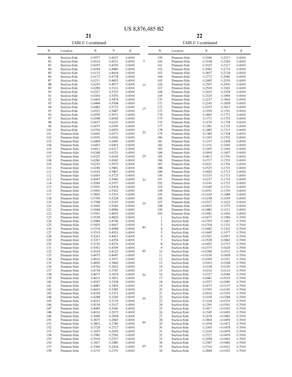
15
16 US 8,876,485 B TABLE 1-continued TABLE 1-continued N Location X Y Z. N Location X Y Z. 193 de -OOO43 O.1949 O.7OOO 71 Suction-Side O.3306 O de -O.O139 O.1940 O.7OOO 5 72 Suction-Side O.3430 O de -O.O235 O.1924 O.7OOO 73 Suction-Side 0.56O7 O.3554 O de -O.O328 O.1900 O.7OOO 74 Suction-Side O.S6SO O.3679 O de -O.O418 O.1864 O.7OOO 75 Suction-Side O.S693 O3804 O de -O.OSO2 O.1815 O.7OOO 76 Suction-Side O.3928 O de O.7OOO 77 Suction-Side O.5777 O.4053 O de -O.O634 O.1675 O.7OOO Suction-Side O.S819 O4178 O Suction-Side -O.O768 O.1832 O Suction-Side O.S861 O4304 O Suction-Side -O.O796 O.1703 O O Suction-Side O.S902 O4429 O Suction-Side -O.O O Suction-Side O.S943 O4554 O Suction-Side -O.O774 O.1442 O Suction-Side O.S984 O46.79 O Suction-Side -O.O736 O.1315 O Suction-Side O.6O2S O4805 O Suction-Side -O.O684 O O Suction-Side O.606S O4930 O Suction-Side -O.O621 O.1079 O Suction-Side O6106 OSOS6 O Suction-Side O.0969 O Suction-Side O.6147 O.S181 O Suction-Side -O.O467 O.O865 O Suction-Side O O Suction-Side -O.O379 O.O766 O Suction-Side O6228 O.S.432 O Suction-Side -O.O286 OO674 O Suction-Side O O Suction-Side -O.O187 O.OS86 O Suction-Side O-6309 O.S683 O Suction-Side -OOO84 O.OSO4 O O 91 Suction-Side O-6349 O.S809 O Suction-Side O.OO22 O.O426 O Suction-Side O.6390 O.S934 O Suction-Side O.O132 O.O352 O Suction-Side O.6430 O6060 O Suction-Side O.O244 O.O.283 O Suction-Side O.6471 O O Suction-Side O.O359 O.O219 O Suction-Side O.6S11 O6311 O Suction-Side O.O476 O.O158 O Suction-Side O.6SS2 O6436 O Suction-Side O.O101 O Suction-Side O.6592 O.6562 O O Suction-Side O.O716 O.0049 O Suction-Side O.6633 O.6687 O Suction-Side O.O839 O O Suction-Side O.6673 O.6813 O Suction-Side O.O963 -OOO45 O.8000 OO Suction-Side O.6709 O.6939 O Suction-Side O OOO86 O.8000 O1 de O6645 O.7045 O Suction-Side O O.O123 O.8000 O2 de O.6551 O.7040 O Suction-Side O O.O15S O O3 de O6494 O.6962 O Suction-Side O O.O183 O.8000 O4 de O.6452 O.6874 O Suction-Side O O.O2O6 O de O O Suction-Side O O.8000 O6 de O.6363 O.67OO O Suction-Side O O.O237 O.8000 O7 de O O.6614 O Suction-Side O O.8000 O8 de O-6272 O.6528 O Suction-Side O O.O248 O de O6224 O6443 O Suction-Side O O.0245 O de O.6176 O.6358 O Suction-Side O O.O236 O de O6128 O.6273 O Suction-Side O2S O de O6079 O6189 O Suction-Side O O.O199 O de O.6O29 O.6105 O Suction-Side O O.O170 O de O6021 O Suction-Side O O.O135 O de O.S938 O Suction-Side O OOO94 O de O Suction-Side OOO46 O de O.S823 O.5773 O Suction-Side O.OOO8 O de O.S691 O Suction-Side O.3392 O.OO69 O de O.5717 O.S609 O Suction-Side O.3506 O.O136 O O de O.S663 O.SS28 O Suction-Side O.3616 O.O2O8 O de O.S608 O.S447 O Suction-Side O.O.285 O de O.S366 O Suction-Side O.382S O.O368 O de O.S497 O.S286 O Suction-Side O.3924 O.O4S5 O de O5441 O.S2O6 O Suction-Side O4019 O.OS47 O de O Suction-Side O4111 O.O642 O de O.S328 OSO48 O Suction-Side O4198 O.0740 O de O4969 O Suction-Side O4283 O.O842 O de O.S212 O4890 O Suction-Side O4364 O.O946 O de O4812 O Suction-Side O.1052 O de OSO94 O.473S O Suction-Side O4516 O-1161 O de O4657 O.8000 S4 Suction-Side O.4588 O.1271 O de O4974 O458O O Suction-Side O4658 O.1383 O de O.4914 O4504 O Suction-Side O.4725 O.1497 O de O4852 O4428 O Suction-Side O.4789 O.1612 O de O.4790 O4353 O Suction-Side O4851 O.1728 O de O.4727 O4278 O Suction-Side O4911 O.1845 O de O4664 O4204 O Suction-Side O4970 O.1964 O de O46OO O4130 O Suction-Side OSO26 O.2083 O de O4536 O.4057 O Suction-Side OSO8O O.22O3 O de O4471 O3984 O Suction-Side O.S134 O-2324 O de O4405 O.3912 O Suction-Side O.S186 O.2445 O de O4338 O3841 O Suction-Side O.S O de O O Suction-Side O.S286 O.2689 O de O42O3 O.3700 O Suction-Side O.S334 O.2812 O de O4134 O.3631 O Suction-Side O.S382 O.2934 O de O4O64 O.3563 O Suction-Side O.S428 O.3058 O de O.3993 O.3495 O Suction-Side O.S474 O.3182 O de O.3922 O.3429 O.8000
17
18
19 31 TABLE 1-continued US 8,876,485 B2 32 TABLE 1-continued Location Y Z. N Location X Y Z O OO O1 O2 O3 O4 05 O6 O7 O O O4957 OSO13 OSO68 O.S122 O.S O.S42O OS O.S603 O.S647 O.S O.S822 O.S865 O.S O.S993 O.6O3S O6078 O612O O6163 O.62OS O.6247 O.629O O O.6417 O.6459 O.6SO2 O6544 O.6586 O6628 O.6671 O.6709 O O.6497 O.6452 O.6406 O.6359 O6312 O6264 O.6215 O.616S O.6114 O.6063 O.6O11 O.S O.S O.S742 O.S686 O.S O.SS16 O.S.458 O.S400 O.S341 O.S282 O.S223 O.S163 O.S102 OSO41 O4979 O4917 O.4854 O.4791 O.4727 O4662 O4597 O.4531 O.2SO O.2747 O.2870 O.2993 O3116 O.3240 O.3364 O3489 O O3864 O.3990 O4116 O4242 O4368 O4494 O4621 O.4747 O4874 OSOOO O.S O.S O.S887 O.6O14 O.6140 O.6267 O-6394 O.6521 O.6647 O.6774 O O.7154 O.7281 O O.7514 O.7434 O O.7084 O.6997 O.6911 O.6826 O.6741 O O6488 O6404 O.6321 O.6238 O.61S6 O6074 O.S993 O.S911 O.S O.SS11 O.S O.S119 OSO42 O4966 O4890 O4814 O.4739 O4664 O de O4464 O4S17 40 de O de O4329 O de O4261 O de O4191 O de O4121 O416O 45 de O4OSO O4O91 46 de O.3979 O4O23 47 de O de O.3833 O de O de O de O.36O7 O de O3S30 O de O S4 de O3S13 55 de O.3293 O de O.3212 O de O.3130 O de O3O46 O de O.2962 O de O de O.2791 O de O.2703 O de O.2615 O3O46 64 de O.2526 O de O.2435 O de O.2344 O de O.2252 O de O O.28SS 69 de O.206S O de O de O.1874 O de O de O.1681 O de O de O.1486 O de O de O.1290 O de O O de O.1092 O.26SO 8O de O.O993 O de O.O894 O de O.O795 O de O.O696 O de O de O.0498 O de O.O4(OO O.266O 87 de O.O3O1 O de O.O2O2 O de O.O103 O de 4 O de -OOO95 O de -O.O.194 O de -O.O293 O de -O.O392 O de -O.0490 O de O de -OO678 O de -O.O de -O.O840 O de -O.O902 O.2416 It will also be appreciated that the airfoil 250 disclosed in the above Table 1 may be scaled up or down geometrically for use in other similar turbine designs. Consequently, the coor dinate values set forth in Table 1 may be scaled upwardly or downwardly such that the airfoil profile shape remains unchanged. A scaled version of the coordinates in Table 1 would be represented by X, Y and Z coordinate values of Table 1, with the X, Y and Z. non-dimensional coordinate values converted to inches, multiplied or divided by a con stant number. An important term in this disclosure is profile. The profile is the range of the variation between measured points on an

20 33 airfoil surface and the ideal position listed in Table 1. The actual profile on a manufactured blade will be different than those in Table 1 and the design is robust to this variation meaning that mechanical and aerodynamic function are not impaired. As noted above, a + or -5% profile tolerance is used herein. The X, Y and Z values are all non-dimensionalized relative to the airfoil height. The disclosed airfoil shape optimizes and is specific to the machine conditions and specifications. The airfoil shape pro vides a unique profile to achieve (1) interaction between other stages in the high pressure turbine; (2) aerodynamic effi ciency; and (3) normalized aerodynamic and mechanical blade loadings. The disclosed loci of points allow the gas turbine or any other suitable turbine to run in an efficient, safe and Smooth manner. As also noted, any scale of the disclosed airfoil may be adopted as long as (1) interaction between other stages in the high pressure turbine; (2) aerodynamic efficiency; and (3) normalized aerodynamic and mechanical bladeloadings are maintained in the scaled turbine. The airfoil 250 described herein thus improves overall gas turbine 100 efficiency. Specifically, the airfoil 250 provides the desired turbine efficiency lapse rate (ISO, hot, cold, part load, etc.). The airfoil 250 also meets all aeromechanics and stress requirements. It should be apparent that the foregoing relates only to certain embodiments of the present application and the result ant patent. Numerous changes and modifications may be made herein by one of ordinary skill in the art without depart ing from the general spirit and scope of the invention as defined by the following claims and the equivalents thereof. We claim: 1. A turbine nozzle comprising an airfoil shape, the airfoil shape having a nominal profile in accordance with Cartesian coordinate values of X, Y and Z set forth in Table 1 wherein the Cartesian coordinate values of X,Y and Zare non-dimen sional values from 0% to 100% convertible to dimensional distances in inches by multiplying the Cartesian coordinate values of X, Y and Z by a height of the airfoil in inches, and wherein X and Y are distances in inches which, when con nected by Smooth continuing arcs, define airfoil profile sec tions at each distance Z, the airfoil profile sections at Z dis tances being joined Smoothly with one another to form a complete airfoil shape. 2. The turbine nozzle of claim 1, wherein the turbine nozzle comprises a stage nozzle of a turbine. 3. The turbine nozzle of claim 1, wherein the turbine nozzle forms part of a stage of a turbine. 4. The turbine nozzle of claim 1, wherein the airfoil shape lies in an envelope within +/-5% of a chord length in a direction normal to any airfoil Surface location. 5. The turbine nozzle of claim 1, wherein the height of the turbine nozzle is 5 inches to 50 inches (12 centimeters to 130 centimeters) in length. 6. The turbine nozzle of claim 1, wherein the X, Y and Z distances are scalable as a function of the same constant or number to provide a scaled-up or scaled-down airfoil. US 8,876,485 B A turbine nozzle comprising a nozzle airfoil having a Suction-side uncoated nominal airfoil profile in accordance with suction-side Cartesian coordinate values of X, Y and Z set forth in Table 1 wherein the Cartesian coordinate values of X, Y and Z are non-dimensional values from 0% to 100% convertible to dimensional distances in inches by multiplying the Cartesian coordinate values of X, Y and Z by a height of the airfoil in inches, and wherein X and Y are distances in inches which, when connected by Smooth continuing arcs, define airfoil profile sections at each Z distance, the airfoil profile sections at the Z distances being joined Smoothly with one another to form a complete Suction-side airfoil shape, the X, Y and Z distances being scalable as a function of the same constant or number to provide a scaled-up or scaled-down airfoil. 8. The turbine nozzle of claim 7, wherein the turbine nozzle comprises a stage nozzle of a turbine. 9. The turbine nozzle of claim 7, wherein the turbine nozzle forms part of a stage of a turbine. 10. The turbine nozzle of claim 7, wherein the airfoil shape lies in an envelope within +/-5% of a chord length in a direction normal to any airfoil Surface location. 11. The turbine nozzle of claim 7, wherein the height of the turbine nozzle is 5 inches to 50 inches (12 centimeters to 130 centimeters) in length. 12. A turbine comprising a plurality of nozzles, each of the nozzles comprising an airfoil having an airfoil shape, the airfoil having a nominal profile in accordance with Cartesian coordinate values of X, Y and Z set forth in Table 1 wherein the Cartesian coordinate values of X,Y and Zare non-dimen sional values from 0% to 100% convertible to dimensional distances in inches by multiplying the Cartesian coordinate values of X, Y and Z by a height of the airfoil in inches, and wherein X and Y are distances in inches which, when con nected by Smooth continuing arcs, define airfoil profile sec tions at each Z distance, the airfoil profile sections at Z dis tances being joined Smoothly with one another to form a complete airfoil shape. 13. The turbine of claim 12, wherein the plurality of nozzles comprises a plurality of stage nozzles of the turbine. 14. The turbine of claim 12, wherein the plurality of nozzles forms part of a stage of a turbine. 15. The turbine of claim 12, wherein the airfoil shapelies in an envelope within +/-5% of a chord length in a direction normal to any airfoil Surface location. 16. The turbine of claim 12, wherein the height of the turbine nozzle is 5 inches to 50 inches (12 centimeters to 130 centimeters) in length. 17. The turbine of claim 12, wherein the X, Y and Z dis tances are scalable as a function of the same constant or number to provide a scaled-up or scaled-down airfoil. 18. The turbine of claim 12, wherein X represents a dis tance parallel to a turbine axis of rotation. k k k k k
21 UNITED STATES PATENT AND TRADEMARK OFFICE CERTIFICATE OF CORRECTION PATENT NO. : 8, B2 Page 1 of 1 APPLICATIONNO. : 13/ DATED : November 4, 2014 INVENTOR(S) : Gustafson et al. It is certified that error appears in the above-identified patent and that said Letters Patent is hereby corrected as shown below: In the Specification Column 3, Line 48, delete the X. Y and Z and insert -- the X, Y and Z --, therefor. Column 4, Line 33, delete Scales, at and insert -- Scales, at, --, therefor. Signed and Sealed this Twenty-sixth Day of May, % 4 Michelle K. Lee Director of the United States Patent and Trademark Office
(12) United States Patent (10) Patent No.: US 8,128,344 B2
 United States Patent (10) Patent No.: US 8,128,344 B2") USOO8128344B2 (12) United States Patent (10) Patent No.: McGovern et al. (45) Date of Patent: Mar. 6, 2012 (54) METHODS AND APPARATUS INVOLVING 6,361,274 B1 3/2002 Kreis et al. SHROUD COOLING 6,406.256
USOO8128344B2 (12) United States Patent (10) Patent No.: McGovern et al. (45) Date of Patent: Mar. 6, 2012 (54) METHODS AND APPARATUS INVOLVING 6,361,274 B1 3/2002 Kreis et al. SHROUD COOLING 6,406.256
(12) United States Patent (10) Patent No.: US 7,052,424 B2
 United States Patent (10) Patent No.: US 7,052,424 B2") US007052424B2 (12) United States Patent (10) Patent No.: US 7,052,424 B2 Kabrich et al. (45) Date of Patent: May 30, 2006 (54) CANTILEVER TOOTH SPROCKET 3,173,301 A * 3/1965 Miller... 474,163 3,899,219
US007052424B2 (12) United States Patent (10) Patent No.: US 7,052,424 B2 Kabrich et al. (45) Date of Patent: May 30, 2006 (54) CANTILEVER TOOTH SPROCKET 3,173,301 A * 3/1965 Miller... 474,163 3,899,219
(12) Patent Application Publication (10) Pub. No.: US 2003/ A1
 Patent Application Publication (10) Pub. No.: US 2003/ A1") US 2003O2O1042A1 (19) United States (12) Patent Application Publication (10) Pub. No.: US 2003/0201042 A1 Lee (43) Pub. Date: Oct. 30, 2003 (54) GOLF CLUB HEAD COVER (22) Filed: Apr. 24, 2002 (75) Inventor:
US 2003O2O1042A1 (19) United States (12) Patent Application Publication (10) Pub. No.: US 2003/0201042 A1 Lee (43) Pub. Date: Oct. 30, 2003 (54) GOLF CLUB HEAD COVER (22) Filed: Apr. 24, 2002 (75) Inventor:
Wang 45 Date of Patent: Sep. 23, 1997
 US005669536A United States Patent (19) 11 Patent Number: Wang 45 Date of Patent: Sep. 23, 1997 54 DEVICE FOR LOCATING SHACKLE LOCK 5,127,562 7/1992 Zane et al...... 224/935 ON BICYCLE FRAME 5,386,961 2/1995
(12) (10) Patent No.: US 7,055,842 B1. Lin (45) Date of Patent: Jun. 6, (54) FOLDING ELECTRIC BICYCLE 6,883,817 B1 4/2005 Chu...
 (10) Patent No.: US 7,055,842 B1. Lin (45) Date of Patent: Jun. 6, (54) FOLDING ELECTRIC BICYCLE 6,883,817 B1 4/2005 Chu...") United States Patent US007055842B1 (12) (10) Patent No.: Lin (45) Date of Patent: Jun. 6, 2006 (54) FOLDING ELECTRIC BICYCLE 6,883,817 B1 4/2005 Chu... 280,278 2002/0175491 A1* 11/2002 Clark... 280/288.4
United States Patent US007055842B1 (12) (10) Patent No.: Lin (45) Date of Patent: Jun. 6, 2006 (54) FOLDING ELECTRIC BICYCLE 6,883,817 B1 4/2005 Chu... 280,278 2002/0175491 A1* 11/2002 Clark... 280/288.4
N3% (12) United States Patent. NNéré. (10) Patent No.: US 7, B2. Rossiter (45) Date of Patent: Nov. 20, 2007
 United States Patent. NNéré. (10) Patent No.: US 7, B2. Rossiter (45) Date of Patent: Nov. 20, 2007") (12) United States Patent US007298.473B2 (10) Patent o.: US 7,298.473 B2 Rossiter (45) Date of Patent: ov. 20, 2007 (54) SPECTROSCOPY CELL 4,587,835 A 5/1986 Adams 4,674,876 A 6/1987 Rossiter... 356,244
(12) United States Patent US007298.473B2 (10) Patent o.: US 7,298.473 B2 Rossiter (45) Date of Patent: ov. 20, 2007 (54) SPECTROSCOPY CELL 4,587,835 A 5/1986 Adams 4,674,876 A 6/1987 Rossiter... 356,244
(12) United States Patent
 United States Patent") (12) United States Patent Dickinson et al. USOO6398197B1 (10) Patent No.: US 6,398,197 B1 (45) Date of Patent: Jun. 4, 2002 (54) WATER CHAMBER (75) Inventors: Philip John Dickinson; David Wixey, both of
(12) United States Patent Dickinson et al. USOO6398197B1 (10) Patent No.: US 6,398,197 B1 (45) Date of Patent: Jun. 4, 2002 (54) WATER CHAMBER (75) Inventors: Philip John Dickinson; David Wixey, both of
E2IB (7/02 ( ) (52) U.S. Cl /19: 464/155 (58) Field of Classification Search / , 175/325.6
 (52) U.S. Cl /19: 464/155 (58) Field of Classification Search / , 175/325.6") US007 186182B2 (12) United States Patent Wenzel et al. (10) Patent No.: (45) Date of Patent: US 7,186,182 B2 Mar. 6, 2007 (54) DRIVE LINE FOR DOWN HOLE MUD MOTOR (76) Inventors: William R. Wenzel, 1738
US007 186182B2 (12) United States Patent Wenzel et al. (10) Patent No.: (45) Date of Patent: US 7,186,182 B2 Mar. 6, 2007 (54) DRIVE LINE FOR DOWN HOLE MUD MOTOR (76) Inventors: William R. Wenzel, 1738
(12) United States Patent (10) Patent No.: US 7,780,559 B2
 United States Patent (10) Patent No.: US 7,780,559 B2") USOO7780559B2 (12) United States Patent () Patent No.: US 7,780,559 B2 Zbikowski et al. (45) Date of Patent: Aug. 24, 20 (54) CHAIN TRANSMISSION (58) Field of Classification Search... 474/212, 474/213,
USOO7780559B2 (12) United States Patent () Patent No.: US 7,780,559 B2 Zbikowski et al. (45) Date of Patent: Aug. 24, 20 (54) CHAIN TRANSMISSION (58) Field of Classification Search... 474/212, 474/213,
III IIII - USOO550545OA United States Patent (19) 11 Patent Number: 5,505,450 Stuff (45) Date of Patent: Apr. 9, 1996
 11 Patent Number: 5,505,450 Stuff (45) Date of Patent: Apr. 9, 1996") III IIII - USOO550545OA United States Patent (19) 11 Patent Number: 5,505,450 Stuff (45) Date of Patent: Apr. 9, 1996 54 GOLF CLUB HEADS WITH MEANS FOR 56) References Cited IMPARTNG CORRECTIVE ACTION U.S.
III IIII - USOO550545OA United States Patent (19) 11 Patent Number: 5,505,450 Stuff (45) Date of Patent: Apr. 9, 1996 54 GOLF CLUB HEADS WITH MEANS FOR 56) References Cited IMPARTNG CORRECTIVE ACTION U.S.
TEPZZ 7_687ZA_T EP A1 (19) (11) EP A1 (12) EUROPEAN PATENT APPLICATION. (43) Date of publication: Bulletin 2014/15
 (11) EP A1 (12) EUROPEAN PATENT APPLICATION. (43) Date of publication: Bulletin 2014/15") (19) TEPZZ 7_687ZA_T (11) EP 2 716 870 A1 (12) EUROPEAN PATENT APPLICATION (43) Date of publication: 09.04.2014 Bulletin 2014/15 (51) Int Cl.: F01D 5/20 (2006.01) (21) Application number: 13187418.2 (22)
(19) TEPZZ 7_687ZA_T (11) EP 2 716 870 A1 (12) EUROPEAN PATENT APPLICATION (43) Date of publication: 09.04.2014 Bulletin 2014/15 (51) Int Cl.: F01D 5/20 (2006.01) (21) Application number: 13187418.2 (22)
(12) United States Patent (10) Patent No.: US 8,757,647 B1
 United States Patent (10) Patent No.: US 8,757,647 B1") US008757647B1 (12) United States Patent (10) Patent No.: US 8,757,647 B1 Su (45) Date of Patent: Jun. 24, 2014 (54) ASSEMBLING STRUCTURE OF SUPPORT (56) References Cited (71) (72) (*) (21) (22) (60) (51)
US008757647B1 (12) United States Patent (10) Patent No.: US 8,757,647 B1 Su (45) Date of Patent: Jun. 24, 2014 (54) ASSEMBLING STRUCTURE OF SUPPORT (56) References Cited (71) (72) (*) (21) (22) (60) (51)
(12) United States Patent
 United States Patent") US008807568B1 (12) United States Patent Ruder (10) Patent No.: (45) Date of Patent: Aug. 19, 2014 (54) BALL GAME (71) Applicant: Christofer Joseph Ruder, Chicago, IL (US) (72) Inventor: Christofer Joseph
US008807568B1 (12) United States Patent Ruder (10) Patent No.: (45) Date of Patent: Aug. 19, 2014 (54) BALL GAME (71) Applicant: Christofer Joseph Ruder, Chicago, IL (US) (72) Inventor: Christofer Joseph
(12) United States Patent (10) Patent No.: US 7,867,058 B2
 United States Patent (10) Patent No.: US 7,867,058 B2") US007867058E32 (12) United States Patent (10) Patent No.: US 7,867,058 B2 Sweeney (45) Date of Patent: Jan. 11, 2011 (54) SPORTS BRA 2,624,881 A * 1/1953 Lee... 450,89 6,176,761 B1* 1/2001 Underhill......
US007867058E32 (12) United States Patent (10) Patent No.: US 7,867,058 B2 Sweeney (45) Date of Patent: Jan. 11, 2011 (54) SPORTS BRA 2,624,881 A * 1/1953 Lee... 450,89 6,176,761 B1* 1/2001 Underhill......
(12) Patent Application Publication (10) Pub. No.: US 2015/ A1
 Patent Application Publication (10) Pub. No.: US 2015/ A1") US 2015O129357A1 (19) United States (12) Patent Application Publication (10) Pub. No.: US 2015/0129357 A1 ROth (43) Pub. Date: May 14, 2015 (54) GUIDED TYPE FALL ARRESTER - BODY (52) U.S. Cl. CONTROL SYSTEM
US 2015O129357A1 (19) United States (12) Patent Application Publication (10) Pub. No.: US 2015/0129357 A1 ROth (43) Pub. Date: May 14, 2015 (54) GUIDED TYPE FALL ARRESTER - BODY (52) U.S. Cl. CONTROL SYSTEM
(12) United States Patent (10) Patent No.: US 6,641,487 B1
 United States Patent (10) Patent No.: US 6,641,487 B1") USOO6641487B1 (12) United States Patent (10) Patent No.: US 6,641,487 B1 Hamburger (45) Date of Patent: Nov. 4, 2003 (54) ADJUSTABLY WEIGHTED GOLF CLUB 4,872,684. A 10/1989 Dippel PUTTER HEAD WITH REMOVABLE
USOO6641487B1 (12) United States Patent (10) Patent No.: US 6,641,487 B1 Hamburger (45) Date of Patent: Nov. 4, 2003 (54) ADJUSTABLY WEIGHTED GOLF CLUB 4,872,684. A 10/1989 Dippel PUTTER HEAD WITH REMOVABLE
(12) (10) Patent No.: US 8,753,083 B2 Lacy et al. (45) Date of Patent: Jun. 17, 2014
 (10) Patent No.: US 8,753,083 B2 Lacy et al. (45) Date of Patent: Jun. 17, 2014") United States Patent USOO8753083B2 (12) () Patent No.: Lacy et al. (45) Date of Patent: Jun. 17, 2014 (54) CURVED COOLING PASSAGES FOR A 6,644,920 B2 11/2003 Beecket al. TURBINE COMPONENT 6,916,150 B2
United States Patent USOO8753083B2 (12) () Patent No.: Lacy et al. (45) Date of Patent: Jun. 17, 2014 (54) CURVED COOLING PASSAGES FOR A 6,644,920 B2 11/2003 Beecket al. TURBINE COMPONENT 6,916,150 B2
(12) Patent Application Publication (10) Pub. No.: US 2009/ A1
 Patent Application Publication (10) Pub. No.: US 2009/ A1") (19) United States US 20090215566A1 (12) Patent Application Publication (10) Pub. No.: US 2009/0215566A1 Braedt (43) Pub. Date: Aug. 27, 2009 (54) MULTIPLE SPROCKETASSEMBLY Publication Classification (75)
(19) United States US 20090215566A1 (12) Patent Application Publication (10) Pub. No.: US 2009/0215566A1 Braedt (43) Pub. Date: Aug. 27, 2009 (54) MULTIPLE SPROCKETASSEMBLY Publication Classification (75)
(12) United States Patent (10) Patent No.: US 8,393,587 B2
 United States Patent (10) Patent No.: US 8,393,587 B2") US008393.587B2 (12) United States Patent (10) Patent No.: US 8,393,587 B2 Hoernig (45) Date of Patent: *Mar. 12, 2013 (54) BATH FIXTURE MOUNTING SYSTEM (56) References Cited (75) Inventor: Victor Hoernig,
US008393.587B2 (12) United States Patent (10) Patent No.: US 8,393,587 B2 Hoernig (45) Date of Patent: *Mar. 12, 2013 (54) BATH FIXTURE MOUNTING SYSTEM (56) References Cited (75) Inventor: Victor Hoernig,
(12) United States Patent (10) Patent No.: US 6,601,826 B1
 United States Patent (10) Patent No.: US 6,601,826 B1") USOO66O1826B1 (12) United States Patent (10) Patent No.: Granata (45) Date of Patent: Aug. 5, 2003 (54) LOW-LEVEL LIFT 4,858,888 A 8/1989 Cruz et al.... 254/122 5,192,053 A * 3/1993 Sehlstedt... 254/122
USOO66O1826B1 (12) United States Patent (10) Patent No.: Granata (45) Date of Patent: Aug. 5, 2003 (54) LOW-LEVEL LIFT 4,858,888 A 8/1989 Cruz et al.... 254/122 5,192,053 A * 3/1993 Sehlstedt... 254/122
(12) United States Patent (10) Patent No.: US 6,834,776 B1
 United States Patent (10) Patent No.: US 6,834,776 B1") USOO6834776B1 (12) United States Patent (10) Patent No.: US 6,834,776 B1 Corvese (45) Date of Patent: Dec. 28, 2004 (54) TENNIS BALL RETRIEVING DEVICE 5,125,654 A 6/1992 Bruno... 473/460 (75) Inventor:
USOO6834776B1 (12) United States Patent (10) Patent No.: US 6,834,776 B1 Corvese (45) Date of Patent: Dec. 28, 2004 (54) TENNIS BALL RETRIEVING DEVICE 5,125,654 A 6/1992 Bruno... 473/460 (75) Inventor:
(12) Patent Application Publication (10) Pub. No.: US 2006/ A1
 Patent Application Publication (10) Pub. No.: US 2006/ A1") (19) United States US 20060049223A1. (12) Patent Application Publication (10) Pub. No.: US 2006/0049223 A1 Mora et al. (43) Pub. Date: Mar. 9, 2006 (54) (76) (21) (22) (60) SCORECARD HOLDER FOR GOLF Inventors:
(19) United States US 20060049223A1. (12) Patent Application Publication (10) Pub. No.: US 2006/0049223 A1 Mora et al. (43) Pub. Date: Mar. 9, 2006 (54) (76) (21) (22) (60) SCORECARD HOLDER FOR GOLF Inventors:
(12) Patent Application Publication (10) Pub. No.: US 2008/ A1
 Patent Application Publication (10) Pub. No.: US 2008/ A1") (19) United States US 20080072365A1 (12) Patent Application Publication (10) Pub. No.: US 2008/0072365A1 Alberto (43) Pub. Date: Mar. 27, 2008 (54) SPACE-SAVING SCUBA DIVING MASK (75) Inventor: Carlos
(19) United States US 20080072365A1 (12) Patent Application Publication (10) Pub. No.: US 2008/0072365A1 Alberto (43) Pub. Date: Mar. 27, 2008 (54) SPACE-SAVING SCUBA DIVING MASK (75) Inventor: Carlos
(12) Patent Application Publication (10) Pub. No.: US 2004/ A1
 Patent Application Publication (10) Pub. No.: US 2004/ A1") US 2004O126242A1 (19) United States (12) Patent Application Publication (10) Pub. No.: US 2004/0126242 A1 Howard et al. (43) Pub. Date: Jul. 1, 2004 (54) BOAT PROPELLER AND GUARD DEVICE (52) U.S. Cl....
US 2004O126242A1 (19) United States (12) Patent Application Publication (10) Pub. No.: US 2004/0126242 A1 Howard et al. (43) Pub. Date: Jul. 1, 2004 (54) BOAT PROPELLER AND GUARD DEVICE (52) U.S. Cl....
United States Patent (19)
") United States Patent (19) Oranje (54) DEVICE FOR SEPARATING LIQUIDS AND/OR SOLIDS FROMA HIGH-PRESSURE GAS STREAM 75 inventor: Leendert Oranje, Haren, Netherlands (73) Assignee: N.V. Nederlandse Gasunie,
United States Patent (19) Oranje (54) DEVICE FOR SEPARATING LIQUIDS AND/OR SOLIDS FROMA HIGH-PRESSURE GAS STREAM 75 inventor: Leendert Oranje, Haren, Netherlands (73) Assignee: N.V. Nederlandse Gasunie,
(12) United States Patent (10) Patent No.: US 6,311,857 B1
 United States Patent (10) Patent No.: US 6,311,857 B1") USOO6311857B1 (12) United States Patent (10) Patent No.: US 6,311,857 B1 Al-Darraii (45) Date of Patent: Nov. 6, 2001 (54) STAND USING HOCKEY STICK SUPPORTS 5,848,716 12/1998 Waranius... 211/85.7 X 6,073,783
USOO6311857B1 (12) United States Patent (10) Patent No.: US 6,311,857 B1 Al-Darraii (45) Date of Patent: Nov. 6, 2001 (54) STAND USING HOCKEY STICK SUPPORTS 5,848,716 12/1998 Waranius... 211/85.7 X 6,073,783
Device for atomizing a liquid
 Page 1 of 6 Device for atomizing a liquid Abstract ( 5 of 5 ) United States Patent 4,504,014 Leuning March 12, 1985 A device (10) for atomizing a liquid is disclosed. The device (10) includes a sprayhead
TEPZZ 6Z4795A T EP A2 (19) (11) EP A2 (12) EUROPEAN PATENT APPLICATION. (43) Date of publication: Bulletin 2013/25
 (11) EP A2 (12) EUROPEAN PATENT APPLICATION. (43) Date of publication: Bulletin 2013/25") (19) TEPZZ 6Z479A T (11) EP 2 604 79 A2 (12) EUROPEAN PATENT APPLICATION (43) Date of publication: 19.06.2013 Bulletin 2013/2 (1) Int Cl.: F01D /18 (2006.01) (21) Application number: 12194748. (22) Date
(19) TEPZZ 6Z479A T (11) EP 2 604 79 A2 (12) EUROPEAN PATENT APPLICATION (43) Date of publication: 19.06.2013 Bulletin 2013/2 (1) Int Cl.: F01D /18 (2006.01) (21) Application number: 12194748. (22) Date
(12) Patent Application Publication (10) Pub. No.: US 2011/ A1
 Patent Application Publication (10) Pub. No.: US 2011/ A1") (19) United States US 2011 0104985A1 (12) Patent Application Publication (10) Pub. No.: US 2011/0104985 A1 LINDER et al. (43) Pub. Date: May 5, 2011 (54) ADAPTABLE MULTI-FUNCTION BRA (52) U.S. Cl.... 450/58;
(19) United States US 2011 0104985A1 (12) Patent Application Publication (10) Pub. No.: US 2011/0104985 A1 LINDER et al. (43) Pub. Date: May 5, 2011 (54) ADAPTABLE MULTI-FUNCTION BRA (52) U.S. Cl.... 450/58;
USOO6O76829A United States Patent (19) 11 Patent Number: 6,076,829 Oblack (45) Date of Patent: Jun. 20, 2000
 11 Patent Number: 6,076,829 Oblack (45) Date of Patent: Jun. 20, 2000") USOO6O76829A United States Patent (19) 11 Patent Number: 6,076,829 Oblack (45) Date of Patent: Jun. 20, 2000 54) BALL THROWINGAPPARATUS AND 3,428,036 2/1969 Parker. METHOD 3,589,349 6/1971 Parker. 3.841,292
USOO6O76829A United States Patent (19) 11 Patent Number: 6,076,829 Oblack (45) Date of Patent: Jun. 20, 2000 54) BALL THROWINGAPPARATUS AND 3,428,036 2/1969 Parker. METHOD 3,589,349 6/1971 Parker. 3.841,292
(12) United States Patent
 United States Patent") (12) United States Patent WOf USOO6273279B1 (10) Patent No.: (45) Date of Patent: Aug. 14, 2001 (54) GOLF TOWEL HOLDER (76) Inventor: Jerrold M. Wolf, 1036 E. Melody La., Fullerton, CA (US) 92831 (*) Notice:
(12) United States Patent WOf USOO6273279B1 (10) Patent No.: (45) Date of Patent: Aug. 14, 2001 (54) GOLF TOWEL HOLDER (76) Inventor: Jerrold M. Wolf, 1036 E. Melody La., Fullerton, CA (US) 92831 (*) Notice:
(12) United States Patent Kholodny et a].
![(12) United States Patent Kholodny et a].](/thumbs/86/93806998.jpg "(12) United States Patent Kholodny et a].") US008677546B1 (12) United States Patent Kholodny et a]. (10) Patent N0.: (45) Date of Patent: US 8,677,546 B1 Mar. 25, 2014 (54) (71) (72) (*) (21) (22) (51) (52) (58) LUFFA SPONGE WITH ROPE HANDLES Applicants:J0seph
US008677546B1 (12) United States Patent Kholodny et a]. (10) Patent N0.: (45) Date of Patent: US 8,677,546 B1 Mar. 25, 2014 (54) (71) (72) (*) (21) (22) (51) (52) (58) LUFFA SPONGE WITH ROPE HANDLES Applicants:J0seph
(12) Patent Application Publication (10) Pub. No.: US 2009/ A1
 Patent Application Publication (10) Pub. No.: US 2009/ A1") (19) United States US 20090005197A1 (12) Patent Application Publication (10) Pub. No.: US 2009/0005197 A1 Mayer (43) Pub. Date: Jan. 1, 2009 (54) HOCKEY STICK HAVING AN ANGLED (52) U.S. Cl.... 473/560;
(19) United States US 20090005197A1 (12) Patent Application Publication (10) Pub. No.: US 2009/0005197 A1 Mayer (43) Pub. Date: Jan. 1, 2009 (54) HOCKEY STICK HAVING AN ANGLED (52) U.S. Cl.... 473/560;
United States Patent (19) Condo et al.
 Condo et al.") United States Patent (19) Condo et al. 54 BOXING TRAINING APPARATUS 75 Inventors: Girolamao Condo; Luigi Trocola, both of Eislingen, Fed. Rep. of Germany 73) Assignee: Petra Condo, Eislingen, Fed. Rep.
United States Patent (19) Condo et al. 54 BOXING TRAINING APPARATUS 75 Inventors: Girolamao Condo; Luigi Trocola, both of Eislingen, Fed. Rep. of Germany 73) Assignee: Petra Condo, Eislingen, Fed. Rep.
(12) Patent Application Publication (10) Pub. No.: US 2005/ A1
 Patent Application Publication (10) Pub. No.: US 2005/ A1") (19) United States US 20050272546A1 (12) Patent Application Publication (10) Pub. No.: US 2005/0272546A1 Reiter (43) Pub. Date: Dec. 8, 2005 (54) RIVETED SPROCKETASSEMBLY (75) Inventor: Markus Reiter,
(19) United States US 20050272546A1 (12) Patent Application Publication (10) Pub. No.: US 2005/0272546A1 Reiter (43) Pub. Date: Dec. 8, 2005 (54) RIVETED SPROCKETASSEMBLY (75) Inventor: Markus Reiter,
(12) United States Patent (10) Patent No.: US 6,368,227 B1
 United States Patent (10) Patent No.: US 6,368,227 B1") USOO6368227B1 (12) United States Patent (10) Patent No.: US 6,368,227 B1 Olson (45) Date of Patent: Apr. 9, 2002 (54) METHOD OF SWINGING ON A SWING 5,413.298 A * 5/1995 Perreault... 248/228 (76) Inventor:
USOO6368227B1 (12) United States Patent (10) Patent No.: US 6,368,227 B1 Olson (45) Date of Patent: Apr. 9, 2002 (54) METHOD OF SWINGING ON A SWING 5,413.298 A * 5/1995 Perreault... 248/228 (76) Inventor:
(12) United States Patent (10) Patent No.: US 6,367,170 B1. Williams (45) Date of Patent: Apr. 9, 2002
 United States Patent (10) Patent No.: US 6,367,170 B1. Williams (45) Date of Patent: Apr. 9, 2002") USOO636717OB1 (12) United States Patent (10) Patent No.: US 6,367,170 B1 Williams (45) Date of Patent: Apr. 9, 2002 (54) PLASTIC TOE CAP AND METHOD OF 5,666,745 A 9/1997 Harwood... 36/77 R MAKING 5,667.857
USOO636717OB1 (12) United States Patent (10) Patent No.: US 6,367,170 B1 Williams (45) Date of Patent: Apr. 9, 2002 (54) PLASTIC TOE CAP AND METHOD OF 5,666,745 A 9/1997 Harwood... 36/77 R MAKING 5,667.857
(12) Patent Application Publication (10) Pub. No.: US 2013/ A1
 Patent Application Publication (10) Pub. No.: US 2013/ A1") US 2013 0186486A1 (19) United States (12) Patent Application Publication (10) Pub. No.: US 2013/0186486A1 Ding (43) Pub. Date: Jul. 25, 2013 (54) SYSTEM FOR AND METHOD OF (52) U.S. Cl. MONITORING FLOW
US 2013 0186486A1 (19) United States (12) Patent Application Publication (10) Pub. No.: US 2013/0186486A1 Ding (43) Pub. Date: Jul. 25, 2013 (54) SYSTEM FOR AND METHOD OF (52) U.S. Cl. MONITORING FLOW
United States Patent (19) Herro
 Herro") United States Patent (19) Herro (54) (76) (22 21 ) 52) (51) 58 (56) ATHLETIC SHOE WITH A DETACHABLE SOLE Inventor: Richard E. Herro, Rte. 5, Mound View Estates, Joliet, Ill. 60436 Filed: Jan. 21, 1976
United States Patent (19) Herro (54) (76) (22 21 ) 52) (51) 58 (56) ATHLETIC SHOE WITH A DETACHABLE SOLE Inventor: Richard E. Herro, Rte. 5, Mound View Estates, Joliet, Ill. 60436 Filed: Jan. 21, 1976
(10) Patent No.: US 7,331,117 B2
 Patent No.: US 7,331,117 B2") 111111 1111111111111111111111111111111111111111111111111111111111111 US007331117B2 (12) United States Patent Lau et al. (10) Patent No.: US 7,331,117 B2 (45) Date of Patent: Feb. 19,2008 (54) CALCANEAL
111111 1111111111111111111111111111111111111111111111111111111111111 US007331117B2 (12) United States Patent Lau et al. (10) Patent No.: US 7,331,117 B2 (45) Date of Patent: Feb. 19,2008 (54) CALCANEAL
. United States Patent (19) Oonuma et al.
 Oonuma et al.") . United States Patent (19) Oonuma et al. 54) BUFFER DEVICE FOR A ROLLER CHAN AND SPROCKET COUPLING (75) Inventors: Koichiro Oonuma, Shiki; Yoshinori ' Kawashima, Sakado; Toshinori Hanai, Kamifukuoka,
. United States Patent (19) Oonuma et al. 54) BUFFER DEVICE FOR A ROLLER CHAN AND SPROCKET COUPLING (75) Inventors: Koichiro Oonuma, Shiki; Yoshinori ' Kawashima, Sakado; Toshinori Hanai, Kamifukuoka,
Blade guard for rotary lawn mowers
 Iowa State University Patents Iowa State University Research Foundation, Inc. 7-27-1976 Blade guard for rotary lawn mowers Wesley F. Buchele Iowa State University Follow this and additional works at: http://lib.dr.iastate.edu/patents
(12) Patent Application Publication (10) Pub. No.: US 2001/ A1
 Patent Application Publication (10) Pub. No.: US 2001/ A1") US 20010O38536A1 (19) United States (12) Patent Application Publication (10) Pub. No.: US 2001/0038536A1 Wiggerman et al. (43) Pub. Date: Nov. 8, 2001 (54) COMBINATION MARINE ACCESSORY Related U.S. Application
US 20010O38536A1 (19) United States (12) Patent Application Publication (10) Pub. No.: US 2001/0038536A1 Wiggerman et al. (43) Pub. Date: Nov. 8, 2001 (54) COMBINATION MARINE ACCESSORY Related U.S. Application
(12) United States Patent (10) Patent No.: US 7,984,723 B2
 United States Patent (10) Patent No.: US 7,984,723 B2") US007.984723B2 (12) United States Patent (10) Patent No.: US 7,984,723 B2 Seivert et al. (45) Date of Patent: Jul. 26, 2011 (54) SELF-STANDING WALKING CANE D113,865 S * 3/1939 Fletcher... D3/7 D138,330
US007.984723B2 (12) United States Patent (10) Patent No.: US 7,984,723 B2 Seivert et al. (45) Date of Patent: Jul. 26, 2011 (54) SELF-STANDING WALKING CANE D113,865 S * 3/1939 Fletcher... D3/7 D138,330
USOO A United States Patent (19) 11 Patent Number: 5,893,786 Stevens 45 Date of Patent: Apr. 13, 1999
 11 Patent Number: 5,893,786 Stevens 45 Date of Patent: Apr. 13, 1999") III IIII USOO589.3786A United States Patent (19) 11 Patent Number: Stevens 45 Date of Patent: Apr. 13, 1999 54 AUTOMATIC TELESCOPING BOUYANT 5,582,127 12/1996 Willis et al.... 116/210 IDENTIFICATION DEVICE
III IIII USOO589.3786A United States Patent (19) 11 Patent Number: Stevens 45 Date of Patent: Apr. 13, 1999 54 AUTOMATIC TELESCOPING BOUYANT 5,582,127 12/1996 Willis et al.... 116/210 IDENTIFICATION DEVICE
(12) United States Patent (10) Patent No.: US 6,881,111 B2. Bridge et al. (45) Date of Patent: Apr. 19, 2005
 United States Patent (10) Patent No.: US 6,881,111 B2. Bridge et al. (45) Date of Patent: Apr. 19, 2005") USOO688.1111B2 (12) United States Patent (10) Patent No.: Bridge et al. (45) Date of Patent: Apr. 19, 2005 (54) SHAFT COUPLER WITH POSITIVE 2,376,714 A 5/1945 Mussen... 15/250.34 ANGULAR AND AXAL LOCKING
USOO688.1111B2 (12) United States Patent (10) Patent No.: Bridge et al. (45) Date of Patent: Apr. 19, 2005 (54) SHAFT COUPLER WITH POSITIVE 2,376,714 A 5/1945 Mussen... 15/250.34 ANGULAR AND AXAL LOCKING
III IIHIII. United States Patent (19) 5,575,725 Nov. 19, Olsavsky. 11 Patent Number: 45 Date of Patent:
 5,575,725 Nov. 19, Olsavsky. 11 Patent Number: 45 Date of Patent:") United States Patent (19) Olsavsky 54 GOLF CLUB HOSEL CONFIGURATION 75) Inventor: Thomas M. Olsavsky, Escondido, Calif. 73) Assignee: Acushnet Company, Fairhaven, Mass. 21 Appl. No.: 465,279 22 Filed:
United States Patent (19) Olsavsky 54 GOLF CLUB HOSEL CONFIGURATION 75) Inventor: Thomas M. Olsavsky, Escondido, Calif. 73) Assignee: Acushnet Company, Fairhaven, Mass. 21 Appl. No.: 465,279 22 Filed:
United States Patent (19) 11 Patent Number: 5,493,591 Kadowaki 45 Date of Patent: Feb. 20, 1996
 11 Patent Number: 5,493,591 Kadowaki 45 Date of Patent: Feb. 20, 1996") USOO5493591A United States Patent (19) 11 Patent Number: Kadowaki 45 Date of Patent: Feb. 20, 1996 54 INTERNAL PUMPFOR NUCLEAR 3,950,220 4/1976 Holz... 376/.391 REACTORS FOREIGN PATENT DOCUMENTS 75) Inventor:
USOO5493591A United States Patent (19) 11 Patent Number: Kadowaki 45 Date of Patent: Feb. 20, 1996 54 INTERNAL PUMPFOR NUCLEAR 3,950,220 4/1976 Holz... 376/.391 REACTORS FOREIGN PATENT DOCUMENTS 75) Inventor:
exercising facility (14), when the arms of the person are to
, when the arms of the person are to") USOO5906563A United States Patent (19) 11 Patent Number: 5,906,563 Pittari (45) Date of Patent: May 25, 1999 54) DUAL EXERCISE BIKE 5,284.462 2/1994 Olschansky et al.... 482/64 5,342,262 8/1994 Hansen......
USOO5906563A United States Patent (19) 11 Patent Number: 5,906,563 Pittari (45) Date of Patent: May 25, 1999 54) DUAL EXERCISE BIKE 5,284.462 2/1994 Olschansky et al.... 482/64 5,342,262 8/1994 Hansen......
(12) United States Patent (10) Patent No.: US 9.249,666 B2
 United States Patent (10) Patent No.: US 9.249,666 B2") USOO9249666B2 (12) United States Patent (10) Patent No.: Wood et al. (45) Date of Patent: Feb. 2, 2016 (54) AIRFOILS FORWAKE DESENSITIZATION (56) References Cited AND METHOD FOR FABRICATING SAME U.S. PATENT
USOO9249666B2 (12) United States Patent (10) Patent No.: Wood et al. (45) Date of Patent: Feb. 2, 2016 (54) AIRFOILS FORWAKE DESENSITIZATION (56) References Cited AND METHOD FOR FABRICATING SAME U.S. PATENT
United States Patent (19)
") United States Patent (19) Yang USOO58394.71A 11 Patent Number: (45) Date of Patent: 5,839,471 Nov. 24, 1998 54). SEALING MEMBER FOR AWALVE 76 Inventor: Tsai Chen Yang, No. 15-11, Tou Ren Lane, Tou Ren
United States Patent (19) Yang USOO58394.71A 11 Patent Number: (45) Date of Patent: 5,839,471 Nov. 24, 1998 54). SEALING MEMBER FOR AWALVE 76 Inventor: Tsai Chen Yang, No. 15-11, Tou Ren Lane, Tou Ren
I
 United States Patent [19] Llort et al. 1111111111111111111111111111111111111111111111111111111111111111111111111111111111 I US005833911A ["1 Patent Number: 5,833,911 [451 Date of Patent: Nov. 10, 1998
Egg...","...7. Primary Examiner-Dean Kramer
 USOO5513884A United States Patent 19 11 Patent Number: Bucher 45) Date of Patent: May 7, 1996 54) GOLF BALL RETRIEVING DEVICE 3,520,569 7/1970 Anderson... 2.94/19.2 3,659,891 5/1972 Pettenon et al....
Hannes et al. 45 Date of Patent: Mar. 3, 1992 (54) BICYCLE RACK FOR PICK-UP TRUCK OTHER PUBLICATIONS
 BICYCLE RACK FOR PICK-UP TRUCK OTHER PUBLICATIONS") III United States Patent (19) 11 USOOSO92504A Patent Number: 5,092,504 Hannes et al. 45 Date of Patent: Mar. 3, 1992 (54) BICYCLE RACK FOR PICK-UP TRUCK OTHER PUBLICATIONS 75) Inventors: Kenneth J. Hannes,
III United States Patent (19) 11 USOOSO92504A Patent Number: 5,092,504 Hannes et al. 45 Date of Patent: Mar. 3, 1992 (54) BICYCLE RACK FOR PICK-UP TRUCK OTHER PUBLICATIONS 75) Inventors: Kenneth J. Hannes,
(12) United States Patent (10) Patent No.: US 7,530,355 B2
 United States Patent (10) Patent No.: US 7,530,355 B2") USOO753 0355B2 (12) United States Patent (10) Patent No.: US 7,530,355 B2 Berghash (45) Date of Patent: May 12, 2009 (54) MOUTH GUARD FOR BRACES (56) References Cited (75) Inventor: Robert Berghash, Williamsville,
USOO753 0355B2 (12) United States Patent (10) Patent No.: US 7,530,355 B2 Berghash (45) Date of Patent: May 12, 2009 (54) MOUTH GUARD FOR BRACES (56) References Cited (75) Inventor: Robert Berghash, Williamsville,
The below identified patent application is available for licensing. Requests for information should be addressed to:
 DEPARTMENT OF THE NAVY OFFICE OF COUNSEL NAVAL UNDERSEA WARFARE CENTER DIVISION 1176 HOWELL STREET NEWPORT Rl 02841-1708 IN REPLY REFER TO Attorney Docket No. 300170 20 March 2018 The below identified
(12) United States Patent
 United States Patent") (12) United States Patent US0093.76922B2 (10) Patent No.: BOmmanakatte et al. (45) Date of Patent: Jun. 28, 2016 (54) INTERIOR CONFIGURATION FORTURBINE (56) References Cited ROTOR BLADE U.S. PATENT DOCUMENTS
(12) United States Patent US0093.76922B2 (10) Patent No.: BOmmanakatte et al. (45) Date of Patent: Jun. 28, 2016 (54) INTERIOR CONFIGURATION FORTURBINE (56) References Cited ROTOR BLADE U.S. PATENT DOCUMENTS
(12) United States Patent (10) Patent No.: US 6,923,737 B1
 United States Patent (10) Patent No.: US 6,923,737 B1") USOO6923737B1 (12) United States Patent (10) Patent No.: US 6,923,737 B1 Walker (45) Date of Patent: Aug. 2, 2005 (54) BASEBALL SWING TRAINING APPARATUS 3,115,129 A 12/1963 Merriman... 124/5 3,115,342
USOO6923737B1 (12) United States Patent (10) Patent No.: US 6,923,737 B1 Walker (45) Date of Patent: Aug. 2, 2005 (54) BASEBALL SWING TRAINING APPARATUS 3,115,129 A 12/1963 Merriman... 124/5 3,115,342
III III IIII. United States Patent (19) Dolan et al. Appl. No.: 311,676 Filed: Sep. 23, 1994
 Dolan et al. Appl. No.: 311,676 Filed: Sep. 23, 1994") United States Patent (19) Dolan et al. 54 76 21 22 51) 52 58 56 HOCKEY STICKWTHERGONOMIC HANDGRIP Inventors: Michael J. Dolan; Thomas Dolan, both of clo Michael Dolan Industrial Design, 31 Union Square
United States Patent (19) Dolan et al. 54 76 21 22 51) 52 58 56 HOCKEY STICKWTHERGONOMIC HANDGRIP Inventors: Michael J. Dolan; Thomas Dolan, both of clo Michael Dolan Industrial Design, 31 Union Square
(12) United States Patent (10) Patent No.: US 8,539,616 B2
 United States Patent (10) Patent No.: US 8,539,616 B2") US0085396.16B2 (12) United States Patent (10) Patent No.: US 8,539,616 B2 Béland et al. (45) Date of Patent: Sep. 24, 2013 (54) SHIRT FOR A HOCKEY PLAYER 3,174,156 3/1965 Dale et al.... 2,115 3,991,420
US0085396.16B2 (12) United States Patent (10) Patent No.: US 8,539,616 B2 Béland et al. (45) Date of Patent: Sep. 24, 2013 (54) SHIRT FOR A HOCKEY PLAYER 3,174,156 3/1965 Dale et al.... 2,115 3,991,420
(12) United States Patent (10) Patent No.: US 9.227,113 B2
 United States Patent (10) Patent No.: US 9.227,113 B2") US009227113B2 (12) United States Patent (10) Patent No.: US 9.227,113 B2 Mace et al. (45) Date of Patent: Jan. 5, 2016 (54) BADMINTON RACKET (56) References Cited (71) Applicant: BABOLATVS, Lyons (FR)
US009227113B2 (12) United States Patent (10) Patent No.: US 9.227,113 B2 Mace et al. (45) Date of Patent: Jan. 5, 2016 (54) BADMINTON RACKET (56) References Cited (71) Applicant: BABOLATVS, Lyons (FR)
United States Patent (19) Curtis
 Curtis") United States Patent (19) Curtis (54) GOALKEEPER'S HOCKEY STOCK WITH BENT SHAFT 75) Inventor: Martin D. Curtis, Bolton, Canada 73 Assignee: Curtis Hockey Inc., Bolton, Canada (21) Appl. No.: 486,126 22
United States Patent (19) Curtis (54) GOALKEEPER'S HOCKEY STOCK WITH BENT SHAFT 75) Inventor: Martin D. Curtis, Bolton, Canada 73 Assignee: Curtis Hockey Inc., Bolton, Canada (21) Appl. No.: 486,126 22
(12) United States Patent
 United States Patent") (12) United States Patent US007029402B2 (10) Patent No.: US 7,029.402 B2 Nakajima (45) Date of Patent: Apr. 18, 2006 (54) GOLF CLUB SHAFT TIP DIAMETER 4,023.802 A * 5/1977 Jepson et al.... 473,309 ADJUSTER,
(12) United States Patent US007029402B2 (10) Patent No.: US 7,029.402 B2 Nakajima (45) Date of Patent: Apr. 18, 2006 (54) GOLF CLUB SHAFT TIP DIAMETER 4,023.802 A * 5/1977 Jepson et al.... 473,309 ADJUSTER,
TEPZZ 69Z 85A T EP A2 (19) (11) EP A2 (12) EUROPEAN PATENT APPLICATION
 (11) EP A2 (12) EUROPEAN PATENT APPLICATION") (19) TEPZZ 69Z 8A T (11) EP 2 690 28 A2 (12) EUROPEAN PATENT APPLICATION (43) Date of publication: 29.01.14 Bulletin 14/0 (21) Application number: 13177476.2 (1) Int Cl.: F03D 7/02 (06.01) F03D 7/00 (06.01)
(19) TEPZZ 69Z 8A T (11) EP 2 690 28 A2 (12) EUROPEAN PATENT APPLICATION (43) Date of publication: 29.01.14 Bulletin 14/0 (21) Application number: 13177476.2 (1) Int Cl.: F03D 7/02 (06.01) F03D 7/00 (06.01)
(12) Patent Application Publication (10) Pub. No.: US 2010/ A1
 Patent Application Publication (10) Pub. No.: US 2010/ A1") (19) United States (12) Patent Application Publication (10) Pub. No.: US 2010/0232953 A1 ANDERSON et al. US 2010O232953A1 (43) Pub. Date: Sep. 16, 2010 (54) HYBRID COMPRESSOR (76) Inventors: STEPHEN A.
(19) United States (12) Patent Application Publication (10) Pub. No.: US 2010/0232953 A1 ANDERSON et al. US 2010O232953A1 (43) Pub. Date: Sep. 16, 2010 (54) HYBRID COMPRESSOR (76) Inventors: STEPHEN A.
(12) United States Patent
 United States Patent") USO0807501 OB2 (12) United States Patent Talavasek et al. (10) Patent No.: (45) Date of Patent: Dec. 13, 2011 (54) REARAXLE SYSTEM FOR BICYCLE (75) Inventors: Jan Talavasek, Morgan Hill, CA (US); Robb
USO0807501 OB2 (12) United States Patent Talavasek et al. (10) Patent No.: (45) Date of Patent: Dec. 13, 2011 (54) REARAXLE SYSTEM FOR BICYCLE (75) Inventors: Jan Talavasek, Morgan Hill, CA (US); Robb
(12) United States Patent (10) Patent No.: US 7, B1
 United States Patent (10) Patent No.: US 7, B1") USOO7066428B1 (12) United States Patent (10) Patent No.: US 7,066.428 B1 Haggard et al. (45) Date of Patent: Jun. 27, 2006 (54) UNFOLDING WING FOR AIR-LAUNCHED, 5,836,541 A * 1 1/1998 Pham... 244/2 LOW
USOO7066428B1 (12) United States Patent (10) Patent No.: US 7,066.428 B1 Haggard et al. (45) Date of Patent: Jun. 27, 2006 (54) UNFOLDING WING FOR AIR-LAUNCHED, 5,836,541 A * 1 1/1998 Pham... 244/2 LOW
58) Field of searby 36, so asso's "... includes a pair of Support Straps connected at opposed ends
 Field of searby 36, so asso's ... includes a pair of Support Straps connected at opposed ends") USOO6113460A United States Patent (19) 11 Patent Number: McKeown (45) Date of Patent: Sep. 5, 2000 54) COMBINATION WOMENS GARMENT AND 2,428,175 8/1947 Norton... 450/31 BREAST SUPPORT 3,527,231 9/1970 Catanese
USOO6113460A United States Patent (19) 11 Patent Number: McKeown (45) Date of Patent: Sep. 5, 2000 54) COMBINATION WOMENS GARMENT AND 2,428,175 8/1947 Norton... 450/31 BREAST SUPPORT 3,527,231 9/1970 Catanese
United States Patent (19) Mills
 Mills") United States Patent (19) Mills 54 75 73 21 22 51 (52) 58 56 PRESSURE ROLLER FUSER WITH COPY WRNKLE CONTROL Inventor: Assignee: Appl. No.: 170,629 Borden H. Mills, Webster, N.Y. Eastman Kodak Company,
United States Patent (19) Mills 54 75 73 21 22 51 (52) 58 56 PRESSURE ROLLER FUSER WITH COPY WRNKLE CONTROL Inventor: Assignee: Appl. No.: 170,629 Borden H. Mills, Webster, N.Y. Eastman Kodak Company,
BALL ACTUATED DOWNHOLE TOOL BACKGROUND
 BALL ACTUATED DOWNHOLE TOOL BACKGROUND Wellbore tools are known that are actuated by actuator balls. A downhole actuator ball is conveyed downhole to actuate one or more wellbore tools, as by landing in
(12) United States Patent
 United States Patent") USOO7690411 B2 (12) United States Patent Wilson (10) Patent No.: (45) Date of Patent: US 7.690,411 B2 Apr. 6, 2010 (54) TIRE PRESSURE CONTROL SYSTEM (76) Inventor: Seth Wilson, 1218 Puerta Del Sol, San
USOO7690411 B2 (12) United States Patent Wilson (10) Patent No.: (45) Date of Patent: US 7.690,411 B2 Apr. 6, 2010 (54) TIRE PRESSURE CONTROL SYSTEM (76) Inventor: Seth Wilson, 1218 Puerta Del Sol, San
Ice skate blade alignment mechanism
 Iowa State University Patents Iowa State University Research Foundation, Inc. 8-11-1992 Ice skate blade alignment mechanism Leon E. Girard Iowa State University Patrick E. Patterson Iowa State University
(12) United States Patent (10) Patent No.: US 8,062,037 B1
 United States Patent (10) Patent No.: US 8,062,037 B1") US008062037B1 (12) United States Patent (10) Patent No.: US 8,062,037 B1 Chapa, Jr. et al. (45) Date of Patent: Nov. 22, 2011 (54) ON-FIELD VISION TRAINING SYSTEM 5.330,176 A 7/1994 Cagney, Jr.... 473,452
US008062037B1 (12) United States Patent (10) Patent No.: US 8,062,037 B1 Chapa, Jr. et al. (45) Date of Patent: Nov. 22, 2011 (54) ON-FIELD VISION TRAINING SYSTEM 5.330,176 A 7/1994 Cagney, Jr.... 473,452
(12) United States Patent (10) Patent No.: US 7,730,548 B1
 United States Patent (10) Patent No.: US 7,730,548 B1") USOO77548B1 (12) United States Patent () Patent No.: US 7,7,548 B1 McCraney (45) Date of Patent: Jun. 8, 20 (54) BALLISTICSVEST PAD COVER 5,127,5 A 7, 1992 Sacks 5,471,906 A 12/1995 Bachner, Jr. et al.
USOO77548B1 (12) United States Patent () Patent No.: US 7,7,548 B1 McCraney (45) Date of Patent: Jun. 8, 20 (54) BALLISTICSVEST PAD COVER 5,127,5 A 7, 1992 Sacks 5,471,906 A 12/1995 Bachner, Jr. et al.
AC EE 44 III. Nice. Ab-Say AAA K. United States Patent (19) Adams. Attorney, Agent, or Firm-Nydegger & Associates 57 ABSTRACT
 Adams. Attorney, Agent, or Firm-Nydegger & Associates 57 ABSTRACT") United States Patent (19) Adams 54 76) 21 22) 51 (52) (58) 56 CONTANER STORAGE SYSTEM Inventor: Kathleen Adams, 3550 Marlesta Dr. San Diego, Calif. 92111 Appl. No.: 587,456 Filed: Jan. 11, 1996 Int. C....
United States Patent (19) Adams 54 76) 21 22) 51 (52) (58) 56 CONTANER STORAGE SYSTEM Inventor: Kathleen Adams, 3550 Marlesta Dr. San Diego, Calif. 92111 Appl. No.: 587,456 Filed: Jan. 11, 1996 Int. C....
(12) United States Patent (10) Patent No.: US 8,733,739 B2
 United States Patent (10) Patent No.: US 8,733,739 B2") US00873.3739B2 (12) United States Patent (10) Patent No.: Mauthner et al. (45) Date of Patent: May 27, 2014 (54) DEVICE THAT INTEGRATES ANASCENDER 2.99 A : 1886 E..................... 252. etzl et al....
US00873.3739B2 (12) United States Patent (10) Patent No.: Mauthner et al. (45) Date of Patent: May 27, 2014 (54) DEVICE THAT INTEGRATES ANASCENDER 2.99 A : 1886 E..................... 252. etzl et al....
DEPARTMENT OF THE NAVY DIVISION NEWPORT OFFICE OF COUNSEL PHONE: FAX: DSN:
 M/W/SEA WARFARE CENTERS NEWPORT DEPARTMENT OF THE NAVY NAVAL UNDERSEA WARFARE CENTER DIVISION NEWPORT OFFICE OF COUNSEL PHONE: 401 832-3653 FAX: 401 832-4432 DSN: 432-3653 Attorney Docket No. 99558 Date:
ZZZZZZYZZZ. Šta Y. (12) Patent Application Publication (10) Pub. No.: US 2011/ A1. (19) United States. Riegerbauer (43) Pub. Date: Dec.
 Patent Application Publication (10) Pub. No.: US 2011/ A1. (19) United States. Riegerbauer (43) Pub. Date: Dec.") (19) United States US 2011 0299988A1 (12) Patent Application Publication (10) Pub. No.: US 2011/0299988 A1 Riegerbauer (43) Pub. Date: Dec. 8, 2011 (54) WATER WHEEL (76) Inventor: (21) Appl. No.: (22)
(19) United States US 2011 0299988A1 (12) Patent Application Publication (10) Pub. No.: US 2011/0299988 A1 Riegerbauer (43) Pub. Date: Dec. 8, 2011 (54) WATER WHEEL (76) Inventor: (21) Appl. No.: (22)
(12) Patent Application Publication (10) Pub. No.: US 2016/ A1
 Patent Application Publication (10) Pub. No.: US 2016/ A1") (19) United States US 2016.0023O86A1 (12) Patent Application Publication (10) Pub. No.: US 2016/0023086 A1 Aamodt (43) Pub. Date: Jan. 28, 2016 (54) SKATEBOARD TRUCKWITH OFFSET (52) U.S. Cl. BUSHING SEATS
(19) United States US 2016.0023O86A1 (12) Patent Application Publication (10) Pub. No.: US 2016/0023086 A1 Aamodt (43) Pub. Date: Jan. 28, 2016 (54) SKATEBOARD TRUCKWITH OFFSET (52) U.S. Cl. BUSHING SEATS
United States Patent (19)
") United States Patent (19) Hepworth et al. 54 CARRYING CASE FOR FLY FISHING ROD AND REEL 76 Inventors: Allen Hepworth; Gordon Smith, both of Port Moody; Walter Johb, Surrey, all of Canada (21) Appl. No.:
United States Patent (19) Hepworth et al. 54 CARRYING CASE FOR FLY FISHING ROD AND REEL 76 Inventors: Allen Hepworth; Gordon Smith, both of Port Moody; Walter Johb, Surrey, all of Canada (21) Appl. No.:
United States Patent (19)
") United States Patent (19) Fujikawa 54 HYDRAULIC CONTROL SYSTEM FOR A ROCK DRILL (75) Inventor: Kozo Fujikawa, Hiroshima, Japan 73) Assignee: Toyo Kogyo Co., Ltd., Hiroshima, Japan 21 Appl. No.: 194,391
United States Patent (19) Fujikawa 54 HYDRAULIC CONTROL SYSTEM FOR A ROCK DRILL (75) Inventor: Kozo Fujikawa, Hiroshima, Japan 73) Assignee: Toyo Kogyo Co., Ltd., Hiroshima, Japan 21 Appl. No.: 194,391
(12) United States Patent (10) Patent No.: US 6,880,421 B2. Watanabe et al. (45) Date of Patent: Apr. 19, 2005
 United States Patent (10) Patent No.: US 6,880,421 B2. Watanabe et al. (45) Date of Patent: Apr. 19, 2005") USOO688.0421B2 (12) United States Patent (10) Patent No.: US 6,880,421 B2 Watanabe et al. (45) Date of Patent: Apr. 19, 2005 (54) ROLLED BALL SCREW AND METHOD FOR (56) References Cited ROLLING BALL SCREW
USOO688.0421B2 (12) United States Patent (10) Patent No.: US 6,880,421 B2 Watanabe et al. (45) Date of Patent: Apr. 19, 2005 (54) ROLLED BALL SCREW AND METHOD FOR (56) References Cited ROLLING BALL SCREW
(12) United States Patent (10) Patent No.: US 6,524,267 B1
 United States Patent (10) Patent No.: US 6,524,267 B1") USOO6524267B1 (12) United States Patent (10) Patent No.: US 6,524,267 B1 Gremel et al. 45) Date of Patent: Feb. 25, 2003 9 (54) VENOUS FILTER FOR ASSISTED VENOUS (56) References Cited RETUR N U.S. PATENT
USOO6524267B1 (12) United States Patent (10) Patent No.: US 6,524,267 B1 Gremel et al. 45) Date of Patent: Feb. 25, 2003 9 (54) VENOUS FILTER FOR ASSISTED VENOUS (56) References Cited RETUR N U.S. PATENT
United States Patent (19) Easton
 Easton") United States Patent (19) Easton 11 Patent Number: 45 Date of Patent: 4,472,928 Sep. 25, 1984 54: COMBINE REEL ANTI-WRAPPING PROTECTOR 76 Inventor: Harlan J. Easton, R.R. 3, Blooming Prairie, Minn. 55917
United States Patent (19) Easton 11 Patent Number: 45 Date of Patent: 4,472,928 Sep. 25, 1984 54: COMBINE REEL ANTI-WRAPPING PROTECTOR 76 Inventor: Harlan J. Easton, R.R. 3, Blooming Prairie, Minn. 55917
System and Method for a Submersible Underwater Storage. Inventor: John D. Houvener
 System and Method for a Submersible Underwater Storage Inventor: John D. Houvener -1- TECHNICAL FIELD [1] The present invention relates to a system for a container submersible underwater, and more specifically
(12) Patent Application Publication (10) Pub. No.: US 2015/ A1
 Patent Application Publication (10) Pub. No.: US 2015/ A1") (19) United States (12) Patent Application Publication (10) Pub. No.: US 2015/0274256A1 Braun et al. US 20150274256A1 (43) Pub. Date: Oct. 1, 2015 (54) (71) (72) (73) (21) (22) (30) DEVICE FOR SHIFTING
(19) United States (12) Patent Application Publication (10) Pub. No.: US 2015/0274256A1 Braun et al. US 20150274256A1 (43) Pub. Date: Oct. 1, 2015 (54) (71) (72) (73) (21) (22) (30) DEVICE FOR SHIFTING
Cagney, Jr. (45) Date of Patent: Jul.19, Inventor: Richard D. Cagney, Jr., 9314 W1991 Johnson
 Date of Patent: Jul.19, Inventor: Richard D. Cagney, Jr., 9314 W1991 Johnson") United States Patent (19) H US005330176A (11 Patent Number: 5,330,176. Cagney, Jr. (45) Date of Patent: Jul.19, 1994 54). STANCE AND STRIDE TRAINING AID 4,932,656 6/1990 Pierce... 273/26 R 5,037,094 8/1991
United States Patent (19) H US005330176A (11 Patent Number: 5,330,176. Cagney, Jr. (45) Date of Patent: Jul.19, 1994 54). STANCE AND STRIDE TRAINING AID 4,932,656 6/1990 Pierce... 273/26 R 5,037,094 8/1991
United States Patent (19) Miettinen
 Miettinen") United States Patent (19) Miettinen (54) (75) (73) 21 22 (51) (52) (58) (56) BOWLING BALL INCLUDING A MEANS FOR DISPLACING THE CENTER OF GRAVITY Inventor: Seppo I. Miettinen, Helsinki, Finland Assignee:
United States Patent (19) Miettinen (54) (75) (73) 21 22 (51) (52) (58) (56) BOWLING BALL INCLUDING A MEANS FOR DISPLACING THE CENTER OF GRAVITY Inventor: Seppo I. Miettinen, Helsinki, Finland Assignee:
Lightweight portable training device to simulate kayaking
 University of Central Florida UCF Patents Patent Lightweight portable training device to simulate kayaking 12-7-2010 Ronald Eaglin University of Central Florida Find similar works at: http://stars.library.ucf.edu/patents
(12) United States Patent
 United States Patent") (12) United States Patent USOO846O13 OB1 (10) Patent No.: US 8.460,130 B1 Earle (45) Date of Patent: Jun. 11, 2013 (54) FOOTBALL SNAPAID (56) References Cited 1 U.S. PATENT DOCUMENTS (76) Inventor: James
(12) United States Patent USOO846O13 OB1 (10) Patent No.: US 8.460,130 B1 Earle (45) Date of Patent: Jun. 11, 2013 (54) FOOTBALL SNAPAID (56) References Cited 1 U.S. PATENT DOCUMENTS (76) Inventor: James
United States Patent (19) Olmr
 Olmr") United States Patent (19) Olmr 54 SAFETY SAW CHAIN 75 Inventor: Jaroslav J. Olmr, Columbia, S.C. 73 Assignee: Textron Inc., Providence, R.I. 21 Appl. No.: 216,150 22 Filed: Dec. 15, 1980 51) Int. Cl....
United States Patent (19) Olmr 54 SAFETY SAW CHAIN 75 Inventor: Jaroslav J. Olmr, Columbia, S.C. 73 Assignee: Textron Inc., Providence, R.I. 21 Appl. No.: 216,150 22 Filed: Dec. 15, 1980 51) Int. Cl....
(12) Patent Application Publication (10) Pub. No.: US 2014/ A1
 Patent Application Publication (10) Pub. No.: US 2014/ A1") (19) United States US 201400.07860A1 (12) Patent Application Publication (10) Pub. No.: US 2014/0007860 A1 LU (43) Pub. Date: Jan. 9, 2014 (54) SMOKELESS PORTABLE ROASTER (57) ABSTRACT (76) Inventor: Chien-Chang
(19) United States US 201400.07860A1 (12) Patent Application Publication (10) Pub. No.: US 2014/0007860 A1 LU (43) Pub. Date: Jan. 9, 2014 (54) SMOKELESS PORTABLE ROASTER (57) ABSTRACT (76) Inventor: Chien-Chang
(12) United States Patent (10) Patent No.: US 7,972,290 B1
 United States Patent (10) Patent No.: US 7,972,290 B1") US007972290B1 (12) United States Patent (10) Patent No.: US 7,972,290 B1 Chisholm (45) Date of Patent: Jul. 5, 2011 (54) DYNAMIC FOOT-ARCHSUPPORT SYSTEM 3.68 A 6. 3. SA, - w alala AND ASSOCATED METHODS
US007972290B1 (12) United States Patent (10) Patent No.: US 7,972,290 B1 Chisholm (45) Date of Patent: Jul. 5, 2011 (54) DYNAMIC FOOT-ARCHSUPPORT SYSTEM 3.68 A 6. 3. SA, - w alala AND ASSOCATED METHODS
Blade guard for rotary lawn mowers
 Iowa State University Patents Iowa State University Research Foundation, Inc. 7-26-1977 Blade guard for rotary lawn mowers Wesley F. Buchele Iowa State University William I. Baldwin Iowa State University
United States Patent (19) Neuhalfen
 Neuhalfen") United States Patent (19) Neuhalfen (54) FOOTBALL SHOULDER PAD WITHOUTER PADS 75 Inventor: Mark Neuhalfen, Villa Park, Ill. 73) Assignee: Wilson Sporting Goods Co., River Grove, Ill. 21 Appl. No.: 502,797
United States Patent (19) Neuhalfen (54) FOOTBALL SHOULDER PAD WITHOUTER PADS 75 Inventor: Mark Neuhalfen, Villa Park, Ill. 73) Assignee: Wilson Sporting Goods Co., River Grove, Ill. 21 Appl. No.: 502,797
(12) Patent Application Publication (10) Pub. No.: US 2006/ A1
 Patent Application Publication (10) Pub. No.: US 2006/ A1") US 20060227285A1 (19) United States (12) Patent Application Publication (10) Pub. No.: Huang (43) Pub. Date: Oct. 12, 2006 (54) DIVING MASK Publication Classification (76) Inventor: Shao-Yin Huang, Taipei
US 20060227285A1 (19) United States (12) Patent Application Publication (10) Pub. No.: Huang (43) Pub. Date: Oct. 12, 2006 (54) DIVING MASK Publication Classification (76) Inventor: Shao-Yin Huang, Taipei
(51) Int. Cl... F04B 25/00 about 250 F., as will not allow the partial pressure of the
 Int. Cl... F04B 25/00 about 250 F., as will not allow the partial pressure of the") USOO58860A United States Patent (19) 11 Patent Number: Cunkelman et al. () Date of Patent: Mar 23, 1999 54) THERMOSTATICALLY CONTROLLED 4,362.462 12/1982 Blotenberg... 417/243 X INTERCOOLER SYSTEM FOR
USOO58860A United States Patent (19) 11 Patent Number: Cunkelman et al. () Date of Patent: Mar 23, 1999 54) THERMOSTATICALLY CONTROLLED 4,362.462 12/1982 Blotenberg... 417/243 X INTERCOOLER SYSTEM FOR
(12) United States Patent
 United States Patent") (12) United States Patent USOO9427708B2 (10) Patent No.: US 9.427,708 B2 Inamura et al. (45) Date of Patent: Aug. 30, 2016 (54) HOLLOW FIBER MEMBRANE MODULE USPC... 96/8 See application file for complete
(12) United States Patent USOO9427708B2 (10) Patent No.: US 9.427,708 B2 Inamura et al. (45) Date of Patent: Aug. 30, 2016 (54) HOLLOW FIBER MEMBRANE MODULE USPC... 96/8 See application file for complete
Semi-automatic firearms
 United States Patent 4,335,643 Gal June 22, 1982 Semi-automatic firearms Abstract Disclosed is a semi-automatic firearm which has a configuration generally similar to a known form of submachine gun insofar
Field of Search 2al Lightweight wind deflectors having Mounting Sleeves
 USOO.5850637A United States Patent (19) 11 Patent Number: 5,850,637 Lewis (45) Date of Patent: Dec. 22, 1998 54). PLIABLE EYEGLASS ATTACHMENT FOR 5,086,789 2/1992 Tichy... 2/209 DEFLECTING WIND AROUND