SPINNAKER POLE TRACK AND GUIDE CONSOLE
|
|
|
- Arleen Stephanie Oliver
- 5 years ago
- Views:
Transcription
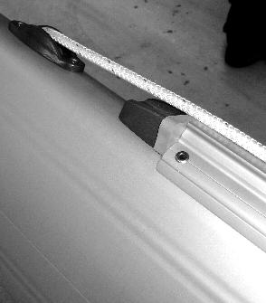
1 1(5) SPINNAKER POLE TRACK AND GUIDE CONSOLE General Assembly single tracks Cut-out for spreader bracket Fitting single guide console Assembly single tracks with bedding Cut-out for spreader bracket Fitting single guide console Assembly double tracks Fitting double guide console Reinforced tracks General This instruction describes fitting single and double spinnaker pole tracks and guide console. Track types: RCB 30W and 25mm. For reference see MB M 1420 NMP. Assembly single tracks 2. Mark the height measure on the A-line. 3. Place the track upper end in level with the height measure, centred over the A-line and fix with packing tape. (Do not cover any predrilled holes). If the spinnaker track passes the mast join, locate the track so that one rivet goes in the middle of the join (see pic. 1). If track passes cast aluminium spreader brackets, see section Cut-out for spreader bracket below before proceeding. 4. Drill the uppermost hole-pair Ø4,9 or Ø6,5 depending on type of rivet. Place rivets in the holes to keep the track in position. 5. Continue to drill every four or five hole-pairs and place rivets in the holes along the way. Make sure the track does not slip out of position. 6. When the end of the track is reached, drill the remaining holes. The inserted rivets will keep the track in position. 7. Remove the track and clean with the air-gun. 8. Grind the track ends with a fine file. C 9. Re-position the track and fasten with rivets. 10. Punch out the mandrel heads. 11. Place the end stops and mark the holes with a pencil. 12. Drill and rivet the upper end stop. If track 25mm/R34 is used, place a washer ( ) under the end stop. If guide console is to be fitted, see section Fitting single guide console below, before proceeding. 13. Drill the lower end stop holes (RCB 30W: with buffer ) to Ø4,9 and tap M6. Fix the lower end stop with M6 screws with the car on the track. Use Schneidmittel. If track 25mm/R34 is used, place a washer ( ) under the end stop. Cut-out for spreader bracket (RCB 30W only) Mark for a cut-out in the track, 3-4 mm each side of the spreader bracket and leave min.15mm of track height to ensure that the cars can pass with clearance, see pic. 2. Make the cut-out and grind all edges. C Place the track on top of the spreader bracket, centred over the A-line. The track will rest on the spreader bracket leaving a gap of 1-2mm. Drill Ø4,9 in the mast in appropriate nearby pre-drilled track-holes and tap M6. If no pre-drilled track-holes are available in the area, drill new holes Ø6,5 in the track and Ø4,9 holes tapped M6 in the mast close to the cutout, see pic. 2.
2 2(5) Force the wings down to close the gap using temporary M6 screws. Release the temporary M6 screws, one at a time, and replace with rivets. Continue with point 4. Fitting single guide console (RCB 30W only) Slide the car onto the track and fix the lower end stop as described in point 12. above. Mark the guide console height measure acc. to mast specification (upper legs centre holes, see pic. 4) and draw a line through the mark perpendicular to the A-line. ( Should be made before the track is assembled.) Adjust the guide console if necessary to fit the mast section. Mark the upper legs holes and fit the guide console upper legs with temporary M6 screws (drill Ø4,9 and tap M6). Check the symmetry of the guide console, mark the lower legs holes and fit the lower legs with temporary M6 screws (drill Ø4,9 and tap M6). Replace the upper and lower legs temporary screws with rivets. Check that the car fits in the guide console. If necessary, adjust the guide console by bending the legs until the car fits in the guide console. Assembly single tracks with bedding (RCB 30W; F194, F212, F228 only) 2. Mark the height measure and draw a line perpendicular to the A-line through the mark. 3. Place the track in level with the height measure, centred over the A-line. If the spinnaker track passes the mast join, locate the track so that one rivet goes in the middle of the join (see pic. 1). Proceed with Cut-out for spreader bracket below. 4. Cut the track to length and grind the edges. C 5. Place the track upper edge in level with the height measure, centred over the A-line and located over the cut out for spreader bracket. 6. Measure out the length of the bedding and place it under the track on both sides of spreader bracket. See pic Grind the bedding ends with a fine file. C 8. Fix the track and bedding with packing tape (hard), centred over the A-line. Do not cover any predrilled holes. 9. Drill the uppermost hole-pair with Ø6,5. Place rivets in the holes to keep the track and bedding in position. 10. Continue to drill every four or five hole-pairs and place rivets in the holes along the way. Make sure the track and bedding does not slip out of position. 11. When the end of the track is reached, drill the remaining holes. The inserted rivets will keep the track in position, remove the packing tape. 12. Loosen the track and bedding, blow clean from burrs. 13. Fit the track with bedding, insert the rivets and fasten it. 14. Punch out the mandrel heads and 15. Place the end stops with buffers and mark the holes with a pencil. 16. Drill Ø6,5 mm and rivet the upper end stop with buffer ( ) see pic 8. If guide console is to be fitted, see section Fitting single guide console below, before proceeding. 17. Put the lower end stop with buffer ( ) in position, drill the lower end stop holes to Ø4,9 and tap M Slide the car onto the track and fix the lower end stop (with buffer) with M6 screws. Use schneidmittel on the screw thread. Cut-out for spreader bracket (RCB 30W only) Mark for a cut-out in the track, 3-4 mm each side of the spreader bracket and leave min.15mm of track height to ensure that the cars can pass with clearance, see pic. 2. Make the cut-out and grind all edges. C
3 3(5) Assembly double tracks (RCB 30W only) Slot layout and location of other fittings may need to be re-located when fitting double spinnaker tracks. Double tracks can not pass aluminium cast spreader brackets on F-sections. 2. Mark the height measure acc. to mast specification and draw a line perpendicular to the A-line through the mark. 3. Place the track in level with the height measure and leave a gap of 4mm (2mm each side of A-line, see pic. 5) between the tracks to allow the cars to pass each other (pic. 5). Fix the tracks with packing tape. If guide console is to be fitted, see section Fitting double guide console below, before proceeding. 4. Drill the uppermost hole-pair Ø4,9 or Ø6,5 depending on type of rivet. Place rivets in the holes to keep the track in position. 5. Continue to drill every four or five hole-pairs and place rivets in the holes along the way. Make sure the track does not slip out of position. 6. When the end of the track is reach, drill the remaining holes. The inserted rivets will keep the track in position. 7. Remove the track and clean with the air-gun. 8. Grind the track ends with a fine file. C 9. Re-position the track and fasten with rivets. 10. Punch out the mandrel heads. 11. Place the end stops and mark the holes with a pencil. 12. Drill and rivet the upper end stop. 13. Drill the lower end stop holes Ø4,9 and tap M6. Fix the lower end stop with M6 screws with the car on track. Use schneidmittel. Fitting double guide console Mark the guide console height measure (upper legs centre holes, see pic. 4) and draw a line through the mark perpendicular to the A-line. Keep the guide console in position and mark the cut-out in the tracks for the centre leg with a pencil, see pic 3. Remove the tracks and make the cut out. Grind the edges. Re-position the tracks and the guide console and check the cut out. Fit the guide console centre leg with MFT M6 screws. Mark the upper legs holes and fit with temporary M6 screws (drill Ø4,9 and tap M6). Check the symmetry of the guide console, mark the lower legs holes and fit the lower legs with temporary M6 screws (drill Ø4,9 and tap M6). Replace the upper and lower legs temporary screws with rivets. Continue with point Before proceeding with point 13 (fitting the lower end stop), slide the two cars onto the tracks and make sure the cars fit inside the guide console. If necessary, adjust the guide console by bending the legs until the cars fit in the guide console. Proceed with point 13.


4 4(5) Reinforced tracks If double fastening is specified, drill and rivet between the original rivets, see pic. 6. If triple fastening is specified, drill and mount two rivets between the original rivets, evenly distributed, see pic. 6. Min. height: 15 mm Pic. 1 Pic. 2 Pic. 3 Pic. 4


5 5(5) Pic. 5 Pic. 6 Pic 7. Pic 8.
HALYARD EXITS, CLEATS, CLUTCHES, WINCH PADS, HANDLE POCKET
 HALYARD EXITS, CLEATS, CLUTCHES, WINCH PADS, HANDLE POCKET 1(6) General CNC-milled masts Cut out using templates Cut out without using templates Assembly Assembly clutch spinnlock ZS/1214 Check point General
2012-June-12 SECOND DRAFT Hobie Getaway Spinnaker Installation Instructions
 SECTION A: INTRODUCTION This unofficial set of installation instructions was written for a 2009 Hobie Getaway, using a 2012 Hobie Spinnaker Kit 20999020. Note from the Author: I had never seen this kit
E Manual Self tacking system 30
 597-205-E 2015-12-09 Manual Self tacking system 30 1 Self tacking system 30, 443-200-10 A self-tacking jib makes life on board a lot easier, in particular for shorthanded crews. The jib sheet is led to
Installation Guide, MPower Echelon Console
 Installation Guide, MPower Echelon Console AC Performance, AC Sport and AC Performance Plus Schwinn Echelon Console (External Routing) 1. Install batteries to console. Mount the console to the bike. 2.
3190A NEO-ANGLE DOOR INSTALLATION INSTRUCTIONS. Series MODEL NO
 NEO-ANGLE DOOR INSTALLATION INSTRUCTIONS Series 30A Please read these instructions carefully to familiarize yourself with the required tools, materials, and installation sequences. The Exploded Diagram
Spinnaker pole kit, dip pole
 595-785-E 2007-01-12 Spinnaker pole kit, dip pole Assembly instructions 96/96 and 99/99 72/72 and 84/84 2 Required tools: Hacksaw Hammer Mandrel (max. diam. ø3,5mm) Drill Drillbit ø6,5mm Rivet gun File
SERIES 2 RAMP OWNER S MANUAL TOOLS REQUIRED: BEFORE YOU BEGIN... Read and understand these instructions before beginning a ramp setup.
 SERIES 2 RAMP OWNER S MANUAL BEFORE YOU BEGIN... Read and understand these instructions before beginning a ramp setup. Use caution and care for your back when lifting, pushing, pulling, folding or unfolding
ORNAMENTAL CANTILEVER GATE INSTRUCTIONS
 U.S.A. Patent Number 5,36,83 ORNAMENTAL CANTILEVER GATE INSTRUCTIONS *NOTICE: Ornamental Cantilever Gates are supplied with rolls of 2 mesh safety screening in sufficient quantities to cover the entire
Fitting Instructions for Single Line Mainsail Reefing System For Yachts Up To 9m (30ft) - Part No
 - Part No") Fitting Instructions for Single Line Mainsail Reefing System For Yachts Up To 9m (30ft) - Part No. 41 130 This single line reefing kit allows reefing control lines to be led aft to the safety of the cockpit.
Fitting Instructions for Single Line Mainsail Reefing System For Yachts Up To 9m (30ft) - Part No. 41 130 This single line reefing kit allows reefing control lines to be led aft to the safety of the cockpit.
Trampoline Installation Instructions
 Congratulations on purchasing an Oz Trampolines Product. Following are detailed setup instructions for your trampoline. Please ensure all boxes and parts are present before continuing. Setting Up Your
rondo aluminium components
 rondo aluminium components The Rondo Aluminium Ceiling System is an alternative to the Rondo DUO Exposed Grid Ceiling System. Unlike the DUO system, the Aluminium Main Tee to Cross Tee intersection is
The slots for 7V4-5 have two predrilled holes. Locate them and connect them with a line. These will be at rib #1,3,4,6.
 7V7-1 Nose Skin The slots for 7V4-5 have two predrilled holes. Locate them and connect them with a line. These will be at rib #1,3,4,6. 7V7-1 Nose Skin The best way to cut the slot is by drilling a series
QUALITY ALUMINUM BOAT LIFTS, INC. INSTRUCTIONS. Dominator Lake Lift
 INSTRUCTIONS Dominator Lake Lift PHONE:251-986-3882 * FAX:251-986-3136 QABLDOMINATORINST.2014 P a g e 1 Quality Aluminum Boat Lifts, INC. Installation Instructions: Dominator Lake Lift Thank you for your
Seldén offer a full range of spinnaker equipment for keelboats. It consists of five aluminium pole sections, three carbon fibre sections, low weight
 56 Seldén offer a full range of spinnaker equipment for keelboats. It consists of five aluminium pole sections, three carbon fibre sections, low weight composite end fittings, telescopic whisker poles,
Assembly Guide ST200 FUNCTIONAL TRAINER
 Assembly Guide ST200 FUNCTIONAL TRAINER Assembly Guide ST200 FUNCTIONAL TRAINER To avoid possible damage to this Functional Trainer, please follow these assembly steps in the correct order. Before proceeding,
Tripod Setup Guide (M-TPx)
") Items needed: 1/2 inch wrench, mast level (M-MLA), medium size wire cutters, crescent wrench, all-purpose grease, tape measure, tie wraps, redi-mix cement (optional), shovel (optional), sledge hammer (for
Items needed: 1/2 inch wrench, mast level (M-MLA), medium size wire cutters, crescent wrench, all-purpose grease, tape measure, tie wraps, redi-mix cement (optional), shovel (optional), sledge hammer (for
02 Push-to-Close Latch
 142 02 Push-to-lose Latch ousing: Polypropylene, black or white Pole pieces and mounting : Steel, zinc plated Magnet:, large: Barium ferrite : Strontium ferrite 7.7 (.30) 13.3 (.52) 6.1 (.24) 23.6 (.93)
Pre-Paint>Fuselage>Empennage>Fit vertical tail fin. Objectives of this task: Materials and equipment required: Fit the spar extender
 Pre-Paint>Fuselage>Empennage>Fit vertical tail fin Objectives of this task: To fit the vertical tail fin to the fuselage, including fitting the static probe, static tube, optional strobe light wiring and
Technical information for hinges
 451 452 Technical information for hinges In the tables on the following pages are listed a large range of hinge variations. Many more variations are possible if hinges with guide tabs are required i.e.
A. TO PREPARE THE MACHINE FOR USE.
 INSTRUCTION MANUAL FOR THE ML120 STRINGING MACHINE. CONTENTS: A. TO PREPARE THE MACHINE FOR USE. 1. The assembly of frame with console and tooltray. 2. Fixing the lever of the tension unit. 3. Putting
COASTAL IN-BOOM FURLING SYSTEM. Installation Manual
 COASTAL IN-BOOM FURLING SYSTEM Installation Manual 1 TABLE OF CONTENTS Page Number 3. Disclaimer 4. Components packing list & required tools 5. Gooseneck bracket location 6. Installation sail track 7.
STOL CH 701. STOL CH 701 Bubble doors Rear view. Front view Right door. Revision 1.0 (10/03/2003) 2003 Zenith Aircraft Co
 2003 Zenith Aircraft Co") Bubble doors Rear view Front view Right door SECTION A - Page 1 of 12 7F19-12D Door Sill See Section 2 Door Final assembly The Door Sill is riveted to the sides of the Upper Tubes 7F12-2 with the wing
Bubble doors Rear view Front view Right door SECTION A - Page 1 of 12 7F19-12D Door Sill See Section 2 Door Final assembly The Door Sill is riveted to the sides of the Upper Tubes 7F12-2 with the wing
Installation Guide Wall Mounted Angled Flagpole
 Installation Guide 1.5m - 4m Angled Flagpole Dimensions Flagpole Dimensions Wall Bracket Dimensions 2m Aluminium 76mm Glassfibre 114.3mm angle from vertical 2000mm 250mm 300mm 1715mm Backplate thickness
Side-of-Pole Mount for 1 Module (SPM1) For Module Types A & B
 For Module Types A & B") Side-of-Pole Mount for 1 Module (SPM1) For Module Types A & B ASSEMBLY INSTRUCTIONS step-by-step assembly and installation Version 1, Rev A PCN 080311-2 SP3363-1 Side-of-Pole Mount for 1 Module (SPM1)
Side-of-Pole Mount for 1 Module (SPM1) For Module Types A & B ASSEMBLY INSTRUCTIONS step-by-step assembly and installation Version 1, Rev A PCN 080311-2 SP3363-1 Side-of-Pole Mount for 1 Module (SPM1)
2. Note that the ropes from the rigging board are secured in the cam cleats of the jib fairleads.
 VII 1. Place the hull, bow into wind, on its trailer, a soft surface, or a rigging board. We strongly recommend making a rigging board; it is simple and inexpensive and greatly simplifies rigging and working
SECTION 23iS/U: SIDE SKINS
 SECTION 23iS/U: SIDE SKINS F-1203G-R BULKHEAD SIDE CHANNEL F-01248-R-1 ARM REST F-01205D SEAT BACK ADJUSTMENT GUIDE, 4 PLACES F-01205B-1 ROLL BAR ATTACH PLATE, F-01248B-1 FUSELAGE PIN LATCH, F-01204J BULKHEAD
FIX ROAD & FIX STRAP cargo securing systems Operating Instruction Manual
 FIX ROAD & FIX STRAP cargo securing systems Operating Instruction Manual NWE NETWORK ENGINEERING OY AB VAT: FI 09628099 1 Introduction Please ensure you read these instructions and understand them fully
PROFURL IN-BOOM REEFING SYSTEM MK 3 R SERIAL NUMBER :... INSTALLATION MANUAL
 13/09/13 I P142GB13D MK 3R PROFURL IN-BOOM REEFING SYSTEM MK 3 R SERIAL NUMBER :... INSTALLATION MANUAL IMPORTANT NOTICE TO RIGGERS : PLEASE GIVE THIS MANUAL TO THE BOAT OWNER AND ASK HIM (HER) TO CAREFULLY
CIRRUS AIRPLANE MAINTENANCE MANUAL MODELS SR22 AND SR22T CHAPTER 55-40: RUDDER GENERAL. Rudder 55-40: RUDDER. 1. General
 CIRRUS AIRPLANE MAINTENANCE MANUAL Rudder CHAPTER 55-40: RUDDER GENERAL 55-40: RUDDER 1. General The rudder provides airplane directional (yaw) control and includes a rudder trim tab used for yaw trim
Installation of 2 Tier In Line Greeting Card Rack
 Installation of 2 Tier In Line Greeting Card Rack Material Sent to Store: Greeting Card Fixtures: 4ft Inline Tier Kit (1 per every 4ft based on planogram) 3ft endcap Tier Kit (will not receive if planogram
MODEL CHEST PULLEY SYSTEM
 MODEL 9180 CHEST PULLEY SYSTEM 1 PARTS LIST FOR CHEST PULLEY Note: Check with your architect or a professional contractor for hardware required to attach the unit to the wall and floor in your facility.
Table of content Introduction 5 1. Part 1. Assembly Tools needed for Assembly Glossary Hulls Mounting the beams 7
 Table of content Introduction 5 1. Part 1. Assembly 6 1.1. Tools needed for Assembly 6 1.2. Glossary 6 1.3. Hulls 7 1.3.1. Mounting the beams 7 1.3.2. Fixing the mast rotation cleats 8 1.3.3. Placing the
ASSEMBLY INSTRUCTIONS
 ASSEMBLY INSTRUCTIONS Ballpark Classics Baseball Game MLB Edition Figure B Read the instructions completely before beginning g assembly. You will need a Phillips screwdriver. 1. Remove the game from the
Fitting Instructions For Slab Reefing Kit Part No For Yachts Up To 8.5m (2 Reefing Points)
") Fitting Instructions For Slab Reefing Kit Part No 41483 For Yachts Up To 8.5m (2 Reefing Points) This system makes reefing your mainsail a quick and easy operation. Just lower the mainsail just below a
Fitting Instructions For Slab Reefing Kit Part No 41483 For Yachts Up To 8.5m (2 Reefing Points) This system makes reefing your mainsail a quick and easy operation. Just lower the mainsail just below a
PROFURL IN-BOOM REEFING SYSTEM MK 2 R SERIAL NUMBER :... INSTALLATION MANUAL
 08/07/13 P140GB13 C MK 2R PROFURL IN-BOOM REEFING SYSTEM MK 2 R SERIAL NUMBER :... INSTALLATION MANUAL IMPORTANT NOTICE TO RIGGERS : PLEASE GIVE THIS MANUAL TO THE BOAT OWNER AND ASK HIM (HER) TO CAREFULLY
Steps for W17, W14,W07, Wing Assembly Sonex #815
 CAUTION: This document is in no way a publication of Sonex Aircraft LLC. or any other corporation. All products mentioned are not necessarily recommended for use, but are included for informational purposes
Marine 6-Boat Free-Standing Racks SKU: Updated November 2011
 Marine 6-Boat Free-Standing Racks SKU: 30-061 Updated November 011 Contains: Marine -Boat Free-Standing Racks (SKU 1-003) Marine 3 rd Boat Expansion Racks (SKU 1-0303) Marine Back Legs (SKU -001) 3 Sets
CIRRUS AIRPLANE MAINTENANCE MANUAL
 RUDDER 1. GENERAL The rudder provides airplane directional (yaw) control and includes a rudder trim tab used for yaw trim adjustment. The rudder is of conventional design with skin, spar and ribs manufactured
VERTICAL SURFBOARD CARRIER READ ME! IMPORTANT WARNING!
 VERTICAL SURFBOARD CARRIER ENG RRAC09 30 min READ ME! Thank you for purchasing a Front Runner Vertical Surfboard Carrier. Before you start, take a moment to familiarize yourself with this Fitting Instruction
Lock-N-Load. Bullet Feeder
 Lock-N-Load Bullet Feeder table of contents steps Overview... 2 List of required hand tools... 2 1: Mounting the Bullet Feeder to the Bench... 3 2: Mounting the Bullet Feed Hopper... 4 3: Bullet Feed Hopper
RATCHET RELEASE SHACKLE
 RATCHET RELEASE SHACKLE INNOVATIVE PILING EQUIPMENT HYDRAULIC PILING HAMMERS EURO RATCHET RELEASE SHACKLE FOR STEEL ERECTION OPERATORS INSTRUCTIONS & SPARE PARTS LIST EXCAVATOR MOUNTED VIBRATORS EXCAVATOR
A-FRAME RESIN IN & OUT FLIP UP LADDER
 A-FRAME RESIN IN & OUT FLIP UP LADDER NE1222 NOTE FOR SAFETY PURPOSES ALL LADDERS SHOULD BE SECURED BY ATTACHING THEM TO THE TOP LEDGE OF THE POOL. (See step 13 for details) In order for the ladder to
FITTING INSTRUCTIONS FOR CASCADE LIGHTWEIGHT LAZY JACK KITS For yachts up to 10.5m (35ft) Part No
 Part No") FITTING INSTRUCTIONS FOR CASCADE LIGHTWEIGHT LAZY JACK KITS For yachts up to 10.5m (35ft) Part No. 41 143 The lightweight Lazy Jack System allows the mainsail to be easily reefed or stowed in all weather
FITTING INSTRUCTIONS FOR CASCADE LIGHTWEIGHT LAZY JACK KITS For yachts up to 10.5m (35ft) Part No. 41 143 The lightweight Lazy Jack System allows the mainsail to be easily reefed or stowed in all weather
BPB26-1 AND SSPB26-1 PATIO BASE INSTALLATION INSTRUCTIONS
 BPB26-1 AND SSPB26-1 PATIO BASE INSTALLATION INSTRUCTIONS WARNING: THIS PATIO BASE IS NOT DESIGNED FOR USE WITH AN LP GAS CYLINDER. WARNING: SEE YOUR GRILL OWNER'S MANUAL FOR PROPER LOCATION, MINIMUM CLEARANCES,
ambiente Installation Guide AmbiClip Systems more than underfloor Customer: Project: Project Reference: Date:
 ambiente more than underfloor Customer: Project: Project Reference: Installation Guide AmbiClip Systems Date: AMBICLIP INSTALLATION GUIDE AMBICLIP FLOOR LAYING INSTRUCTIONS 1 Set up pipe decoiler and all
Final Assembly Instructions Bikes with 16 Wheel Size
 Final Assembly Instructions Bikes with 16 Wheel Size Thank you for buying your new bicycle from L.L.Bean. Read these instructions carefully before beginning the final assembly. Prior to shipping, our expert
Forestay fittings and halyard routing
 Festay fittings and halyard routing Cutter stay on masthead rigs On fractional rigs the festay fitting is either fitted directly on to the mast combined with the halyard box (Seldén combi boxes). The festay
JEEP CHEROKEE XJ DIY FRONT BUMPER ASSEMBLY INSTRUCTIONS
 JEEP CHEROKEE XJ DIY FRONT BUMPER ASSEMBLY INSTRUCTIONS Please read the mounting instructions below carefully before attempting to install. Thank you for purchasing your new DIY Bumper from JcrOffroad!
MODEL / SINGLE and DUPLEX PULLEY SYSTEMS
 MODEL 922181/922182 SINGLE and DUPLEX PULLEY SYSTEMS MODEL 922181 SINGLE PULLEY SYSTEM MODEL 922182 DUPLEX PULLEY SYSTEM 1 PARTS LIST FOR SINGLE/DUPLEX COLUMN PULLEYS Note: Check with your architect or
How To: Install a 1 Body Lift using Hockey Pucks A CFans Members Mod Project by grandmastrblastr
 How To: Install a 1 Body Lift using Hockey Pucks A CFans Members Mod Project by grandmastrblastr Skill Level: Easy Disclaimer: Please use caution and seek professional assistance when necessary. ColoradoFans.com,
Installation Instructions
 116-3027, 116-3017 X-Pando Adjustable Steel Protector Installation Instructions 1404 N. Marshall Ave. El Cajon CA. 92020 For technical support call us at (800) 368-3075 NB 6/28/10 607-0112 Step 1. Mounting
CHAINLESS ANCHORING SYSTEM USER MANUAL
 CHAINLESS ANCHORING SYSTEM USER MANUAL Introduction..................................................... 1 Setting up the Chainless Anchoring System............................ 4 Set up Procedure............................................
Load Ring bolted > VWBG < in pink
 RUD-Art.-Nr.: 8503693-EN / 03.014 Load Ring bolted > VWBG < in pink EN Safety instructions This safety instruction/declaration has to be kept on file for the whole lifetime of the product. Translation
CHAPTER 5 REWIND STARTERS
 GENERAL INFORMATION CHAPTER 5 REWIND S Rewind starters used on vertical shaft Tecumseh engines are top mount horizontal pull style or side mount vertical pull style. Horizontal shaft engines use side mounted
INSTALLATION INSTRUCTIONS
 INSTALLATION INSTRUCTIONS Accessory (ROOF) P/N 08L07-E09-100 Application 6 PILOT Publications No. Issue Date JUN 5 PARTS LIST 6 Washers Bicycle attachment 2 Brackets Hex wrench 4 Knobs 2 Keys 1 Rear Bracket
RUDDER KIT INSTRUCTIONS
 A I N S T R U C T I O N S RUDDER KIT INSTRUCTIONS TARPON 0/40/60/60i The Tarpon series is designed as a high performance sit-on-top kayak tailored for the sport paddler. Our rudder system is designed to
Hydraulic systems 2 Dimensioning
 595-177-E 2015-12-07 Hydraulic systems 2 Dimensioning Hydraulic systems 2... 1 Dimensioning... 1 Introduction... 3 1 HOSE LENGTH CALCULATION... 4 1.1 Definition of hydraulic hose length... 4 1.2 Hose length
8MAY15 US RACK, Inc Falcon Drive, Madera, CA
 8MAY15 US RACK, Inc. - 2850 Falcon Drive, Madera, CA 93637-559-661-3050 INSTRUCTIONS for Bedrail-mounted MOTORCYCLE RACK, Model 2001-4TRA WARNING: Do NOT attempt to install or use this rack without following
ZODIAC CH 601 XL. Tail Dragger (TD) or tail wheel configuration. TD configuration (shown with dual stick option and center console).
 or tail wheel configuration. TD configuration (shown with dual stick option and center console).") Tail Dragger (TD) or tail wheel configuration TD configuration (shown with dual stick option and center console). Ref 6B11-2 No cutout in the side skin 6B11-2 for the gear channel 6B5-5 When converting
Tail Dragger (TD) or tail wheel configuration TD configuration (shown with dual stick option and center console). Ref 6B11-2 No cutout in the side skin 6B11-2 for the gear channel 6B5-5 When converting
COMPLETE WHEEL-BUILDING INSTRUCTIONS
 COMPLETE WHEEL-BUILDING INSTRUCTIONS NOTE: Before using this book and for the correct crossing of spokes for both hub flanges of each individual wheel, please refer to the latest Spoke Length Chart. (Instructions
MSA Latchways Ladder System
 Systems overview 1 of 13 Important information Individuals or organisations carrying out the installation of a MSA Latchways ladder fall protection system shall read, understand and follow these instructions
- Written price quotations are valid for 30 days from the date of the quote unless otherwise noted.
 SPECIFICATIONS - All material is solid brass with a #8 mirror finish unless otherwise noted. - All material sold by length is priced in one foot increments. ORDERING PROCEDURE - Use a Purchase Order number.
READ ALL INSTRUCTIONS AND WARNINGS BEFORE USING THIS PRODUCT.
 Drywall Stills DS1830 Max Weight Capacity 225 Lb READ ALL INSTRUCTIONS AND WARNINGS BEFORE USING THIS PRODUCT. This manual provides important information on proper operation & maintenance. Every effort
Cat Fence Installation Instructions for Regular and Snow Protection Kits with Extra Posts. List of items shown
 CF-INST-E, Rev., 0/7/ Cat Fence Installation Instructions for Regular and Protection s with Extra Posts Attachment Close-up Regular Regular Post with Post Attached A B F K J E C D I G, H L List of items
Gurney Flap for WRX and STI w/low Profile Trunk Spoiler
 Gurney Flap for 2015+ WRX and STI w/low Profile Trunk Spoiler 2017-12-05 Thank you for purchasing this PERRIN product for your car! Installation of this product should only be performed by persons experienced
Trogear Bowsprit Through Hull Installation Manual
 Trogear Marine Products, LLC www.trogear.com info@trogear.com 866-616-2978 Trogear Bowsprit Through Hull Installation Manual Congratulations on your purchase of the Trogear Bowsprit which can be installed
PCB accessories. PCB handle C. PCB retainer C. Order Information. Note. Order Information
 PCB accessories PCB handle C PCB accessoriesmain CataloguePart number in bold face type: ready for despatch within 2 working dayspart number in normal type: ready for despatch within 0 working days For
INSTALLATION INSTRUCTIONS
 INSTALLATION INSTRUCTIONS Accessory P/N 08L07-E09-100 Application 2013 ODYSSEY Publications No. AII 13265 Issue Date AUG 2012 Put this information in the glove box with the vehicle owner s manual. PARTS
 SLIDING RAIL SYSTEM 208-580-1904 www.fishfighterproducts.com FFP sliding Rail system The FFP Sliding Rail system will allow you to easily adjust the location of your rod holders, tackle trays, or just
Rekluse Motor Sports. TCS Clutch Baskets CRF 450R/X CR 250R
 Rekluse Motor Sports TCS Clutch Baskets CRF 450R/X 2002 2008 CR 250R 1992 2006 Installation Guide Copyright 2006 Rekluse Motor Sports TCS Revision 1.000 RMS 4113 195-4113 Manual Revision: 081606 Rekluse
F-1279-R UPPER RIGHT SKIN F-1280-R RIGHT SIDE SKIN F-1281-R LOWER RIGHT SKIN F-1208-R FUSELAGE FRAME
 F-1282-R BOTTOM RIGHT SKIN F-1283C J-STIFFENER F-1278 TOP SKIN F-00009-L ADAHRS BRACKET F-00009-R ADAHRS BRACKET F-1279-R UPPER RIGHT SKIN F-1280-R RIGHT SIDE SKIN SECTION 10: TAILCONE F-1279-L UPPER LEFT
BICYCLE ACCESS RAMP INSTALLATION INSTRUCTIONS. Customer Service all4cycling.com.au
 BICYCLE ACCESS RAMP INSTALLATION INSTRUCTIONS Customer Service 1300 429 254 all4cycling.com.au Thanks for buying our Bicycle Access Ramp! You re now the proud owner of the Bike Fixation Bicycle Access
Ref Part Part # Qty Letter A Rudder Catcher B X 1/2 PH Bolts C Rudder Bracket
 Ref Part Part # Qty A Rudder Catcher 07.2694.0000 1 J B Q A B 10-32 X 1/2 PH Bolts 07.2136.0000 10 C Rudder Bracket 07.2689.0000 1 D Kayak Pad Eye 01.1315.0430 2 E Cherry Rivets 01.1315.0459 4 H T N P
Stand-N-Fish FULL DETAIL INSTALLATION INSTRUCTIONS
 1 Stand-N-Fish FULL DETAIL INSTALLATION INSTRUCTIONS Thank you for purchasing the incredible new Stand-N-Fish Kayak Fishing System. Once installed on your kayak the Stand-N-Fish will take your kayak fishing
Model: LG IP CL ADULT SUPERVISION REQUIRED
 420969 Model: LG IP CL 313 Regina Avenue Rahway, NJ 07065-4891 732-574-1500 GENERAL Before you start, check to see that you have the correct number of parts. Use the packing list on the next page. Carefully
BARRIER OFFSET 0" A 6" 6" A 12" 12" A 26" A 26" 3A OR 4A L OR S * ** L OR S L OR S
 ACCEPTABLE (TCB) TYPES AND ANCHORING DETAILS BASED ON UNDERLYING SURFACE TYPE AND BARRIER OFFSET FROM DROP-OFF BARRIER OFFSET UNDERLYING SURFACE 0" A 6" 6" A 12" 12" A 26" A 26" TCB TYPE DETAIL TCB TYPE
Methylethycetone (MEC) - PMS 60 polyurethane glue - Grease - White silicone
 - PMS 60 polyurethane glue - Grease - White silicone") CHAPTER PLAN page : 1/8 SAILING BOAT SUSPENDED WITHOUT DECK BEARING SAILING BOAT SUSPENDED WITH DECK BEARING SAILING BOAT SUSPENDED WITH AUTOMATIC BEARING ALIGNMENT RUDDER SYSTEM FOR ANTARES MOTOR BOAT
CHAPTER PLAN page : 1/8 SAILING BOAT SUSPENDED WITHOUT DECK BEARING SAILING BOAT SUSPENDED WITH DECK BEARING SAILING BOAT SUSPENDED WITH AUTOMATIC BEARING ALIGNMENT RUDDER SYSTEM FOR ANTARES MOTOR BOAT
OWNER'S MANUAL LOCK-N-LOAD BULLET FEEDER (PISTOL)
") OWNER'S MANUAL LOCK-N-LOAD BULLET FEEDER (PISTOL) Table of Contents ASSEMBLY ASSEMBLY Pistol Bullet Feeder... Page 3 CHANGE-OVERS The Hornady Lock-N-Load Pistol Bullet Feeder is capable of feeding most
OWNER'S MANUAL LOCK-N-LOAD BULLET FEEDER (PISTOL) Table of Contents ASSEMBLY ASSEMBLY Pistol Bullet Feeder... Page 3 CHANGE-OVERS The Hornady Lock-N-Load Pistol Bullet Feeder is capable of feeding most
PRO1030 Bi-Directional Assembly Replacement
 PRO1030 Bi-Directional Assembly Replacement 1. Remove both side covers using the Crank and Cover Removal procedure. Fig. 1 2. Disconnect both brake cables (not shown) from the brake (S3611). (Fig. 1) 3.
INSTALLING THE TRIDENT 11, 13 OR 15 RUDDER
 INSTALLING THE TRIDENT 11, 13 OR 15 RUDDER Parts Included: Steering Parts: Foot Rail Parts: Rudder Parts: Retraction Parts: 4 - Rubber 2 - Rail Assemblies 1 - Rudder Body 1 - Rudder Retraction Grommets
Straightaway 130. Sliding & Folding Door Systems. Product Overview. Features. Technical Specifications. Coburn Product Data Sheet
 Sliding & Folding Door Systems Coburn Product Data Sheet Straightaway 0 Sliding & Folding Door Systems Product Overview The Straightaway 0 is a quiet and dependable system designed for interior and exterior
Solar panel. C ground profile (N-S) Omega ballast plate
 Omega ballast plate") Instruction Manual AvaSolar -Roof (patent: 1018790 A3) 1 Parts 8 4 3 1 2 7 9 5 6 1 Mounting brackets AvaSolar -Roof 4 Solar panel 7 L-profile 2 AvaSolar -cover 5 C ground profile (N-S) 8 Clamps 3 AvaSolar
Instruction Manual AvaSolar -Roof (patent: 1018790 A3) 1 Parts 8 4 3 1 2 7 9 5 6 1 Mounting brackets AvaSolar -Roof 4 Solar panel 7 L-profile 2 AvaSolar -cover 5 C ground profile (N-S) 8 Clamps 3 AvaSolar
S110 Steel Level Panel Installation Instructions
 S110 Steel Level Panel Installation Instructions NOTE: Fairway Architectural Railing Solutions will not be held liable for incorrect or unsafe installations by installer. It is the installer s resposibility
AGM 33 PIKE ALL FIBERGLASS. Specifications Length: 92 Diameter 5.5 Weight: 24 lbs Motor Mount: 75mm Fins: 6-3/16 G10 CP: 68 from nose tip Parts List
 ALL FIBERGLASS AGM 33 PIKE Specifications Length: 92 Diameter 5.5 Weight: 24 lbs Motor Mount: 75mm Fins: 6-3/16 G10 CP: 68 from nose tip Parts List (1) Filament Wound Nose Cone w/ Metal Tip (1) Nose Cone
Tread Brake Assembly Instructions
 reated: 9/06/202, Revision: 2/20/204 Tread rake ssembly Instructions Table of ontents: Lower rake omponents..2-4 able rake ssembly: rake Handle omponents..5-7 able ssembly....8 Tee Handle rake ssembly...9-0
Keel-stepped and deck-stepped masts,
 Keel-stepped and deck-stepped masts, C-sections and F-sections The T-base and deck ring systems are made to fit both Seldén s conventional mast sections and their matching furling sections. They are also
MODEL TRIPEX PULLEY SYSTEM
 MODEL 922184 TRIPEX PULLEY SYSTEM 1 PARTS LIST FOR TRIPEX PULLEY SYSTEM Note: Check with your architect or a professional contractor for hardware required to attach the unit to the wall and floor in your
CLIMBING STEEL POLES INSTRUCTOR GENERAL LESSON OUTLINE ONLINE/CLASSROOM SESSION
 INSTRUCTOR GENERAL LESSON OUTLINE ONLINE/CLASSROOM SESSION This lesson describes different steel pole steps and discusses strategies for climbing, descending, and positioning steel poles to reach work
CO V E R S TA R AU TO MAT I C S A F E T Y CO V E R INSTALLATION GUIDE
 CO V E R S TA R AU TO MAT I C S A F E T Y CO V E R DECKMOUNT SYSTEM INSTALLATION GUIDE SECTIONS System Parts Reference...3 Standard Top Track...4-6 Mechanism... 7-10 Cover Fabric...11-16 Home Owner & Builder
SEADUCER BOATS GAS SPORT HYDRO
 SEADUCER BOATS GAS SPORT HYDRO COME VISIT US ON THE WEB AT WWW.SEADUCERBOATS.COM 2 - Pkg. Of 440 push rod ends 2 - Pkg. of solder-on rod ends 2 -water outlet fitting 1-1/4" prop nut 1 -.250" x 30" flex
EF-140S and EF-140S/H 40 Meter Linear Loaded Dipole FREQUENCY COVERAGE: MHz (adjustable)
") EF-140S and EF-140S/H 40 Meter Linear Loaded Dipole FREQUENCY COVERAGE: 6.850-7.500 MHz (adjustable) Force 12 Legacy Manual 2014 RF Acquisitions International, Inc. 566 West Crete Circle, Unit 1, Grand
EF-140S and EF-140S/H 40 Meter Linear Loaded Dipole FREQUENCY COVERAGE: 6.850-7.500 MHz (adjustable) Force 12 Legacy Manual 2014 RF Acquisitions International, Inc. 566 West Crete Circle, Unit 1, Grand
L.Ph. Bolander & Sons 1355 Evans Ave. 800/
 L.Ph. Bolander & Sons 1355 Evans Ave. 800/434-5611 San Francisco, Ca. 94124 Fax 415/648-0402 GOUNDSET ALUMINUM FLAGPOLE INSTALLATION INSTRUCTIONS STEP 1: DIG THE HOLE TO THE DIMENSIONS LISTED BELOW STEP
SECTION 10iS: TAILCONE
 VAN'S AIRCRAFT, INC. F-1282-R BOTTOM RIGHT SKIN F-1283C J-STIFFENER F-1278 TOP SKIN F-00009-L ADAHRS BRACKET F-00009-R ADAHRS BRACKET F-1279-R UPPER RIGHT SKIN F-1280-R RIGHT SIDE SKIN SECTION 10iS: TAILCONE
INSTALLATION INSTRUCTIONS
 INSTALLATION INSTRUCTIONS Accessory (ROOF) P/N 08L07-E09-100 Application 2013 CROSSTOUR Publications No. AII 13168 Issue Date NOV 2012 PARTS LIST 6 Washers Bicycle attachment 2 Brackets Hex wrench 4 Thumbwheel
Making Spars for the Schooner Jeanette
 Making Spars for the Schooner Jeanette..... by Byron Rosenbaum Figure 1. Byron Rosenbaum s 1:16-scale radio-controlled model of the schooner Jeanette. All photographs by the builder. The spars required
New Product Update - September 2017
 New Product Update September 2017 Series 1 Ball Bearing Utility Blocks Available Now With a sheave diameter of 1mm these are the smallest and lightest ball bearing blocks available! The single block delivers
AVA Building Instructions
 Suggested Assembly Sequence: AVA Building Instructions 1. Insert fittings in rudder and trial fit rudder on boom 2. Attach stab to v-mount and position ahead of rudder ¼, sanding the v-mount as needed.
F13.11 PARALLEL HINGES F13 PROJECT-OUT WINDOWS AND TOP HUNG WINDOWS
 F13 PROJECT-OUT WINDOWS AND TOP HUNG WINDOWS F13.11 01.06.2018 Waregemstraat 5-9870 Zulte - Belgium - T. +32 9 388 88 81 - F. +32 9 388 88 21 - commercial@sobinco.com - www.sobinco.com CONTENTS 1. General...F13.11.03
Specifications Testing & Adjusting Disassembly & Assembly
 SB4191E00 Jul. 2005 Specifications Testing & Adjusting Supplement for Quad Lift Mast D20/25/30/32/33S-3 G/GC20/25/30/32P-3 G/GC20/25/30/32E-3 Important Safety Information Most accidents involving product
Thank you for purchasing a WIKE BOX BIKE!
 Thank you for purchasing a WIKE BOX BIKE! Contents Safety.....3 Front wheel.4 Kickstand..5 Handle Bar & Box 6 Seat post and Saddle 7 Final pre-ride check 8 Tools needed to assemble Bike: -High table or