Proposed Groundwater Assessment Work Plan (Rev.1)
|
|
|
- Myra Perkins
- 5 years ago
- Views:
Transcription
1 Allen Steam Station Ash Basin Proposed Groundwater Assessment Work Plan (Rev.1) NPDES Permit NC December 30, 2014
2 Table of Contents Duke Energy Carolinas, LLC Proposed Groundwater Assessment Work Plan Allen Steam Station Ash Basin Table of Contents Table of Contents... i Executive Summary... ES Introduction Site History Plant Description Ash Basin Description Regulatory Requirements Receptor Information Regional Geology and Hydrogeology Initial Conceptual Site Model Physical Site Characteristics Ash Basin Ash Landfill Structural Fills Ash Storage Source Characteristics Hydrogeologic Site Characteristics Compliance Groundwater Monitoring Assessment Work Plan Subsurface Exploration Ash and Soil Borings Shallow Monitoring Wells Deep Monitoring Wells Bedrock Monitoring Wells Well Completion and Development Hydrogeologic Evaluation Testing Groundwater Sampling and Analysis Existing Compliance and Voluntary Monitoring Wells Onsite Water Supply Wells Speciation of Select Inorganics Surface Water and Seep Sampling Surface Water Samples...30 i
3 Duke Energy Carolinas, LLC Proposed Groundwater Assessment Work Plan Allen Steam Station Ash Basin Table of Contents Seep Samples Sediment Samples Field and Sampling Quality Assurance/Quality Control Procedures Field Logbooks Field Data Records Sample Identification Field Equipment Calibration Sample Custody Requirements Quality Assurance and Quality Control Samples Decontamination Procedures Site Hydrogeologic Conceptual Model Site-Specific Background Concentrations Groundwater Fate and Transport Model MODFLOW/MT3DMS Model Development of Kd Terms MODFLOW/MT3DMS Modeling Process Hydrostratigraphic Layer Development Domain of Conceptual Groundwater Flow Model Boundary Conditions for Conceptual Groundwater Flow Model Groundwater Impacts to Surface Water Risk Assessment Human Health Risk Assessment Site-Specific Risk-Based Remediation Standards Ecological Risk Assessment CSA Report Proposed Schedule References...53 Appendix A Notice of Regulatory Requirements Letter from John E. Skvarla, III, Secretary, State of North Carolina, to Paul Newton, Duke Energy, dated August 13, Appendix B Review of Groundwater Assessment Work Plan Letter from S. Jay Zimmerman, Chief, Water Quality Regional Operations Section, NCDENR, To Harry Sideris, Duke Energy, dated November 4, ii
4 Figures Duke Energy Carolinas, LLC Proposed Groundwater Assessment Work Plan Allen Steam Station Ash Basin Table of Contents 1. Site Location Map 2. Site Layout Map 3. Proposed Well and Sample Location Map Tables 1. Groundwater Monitoring Requirements 2. Monitoring Well Locations 3. Exceedances of 2L Standards 4. Environmental Exploration and Sampling Plan 5. Soil and Ash Parameters and Analytical Methods 6. Groundwater, Surface Water, and Seep Parameters and Constituent Analytical Methods 7. Historical Groundwater Analytical Results (Compliance and Voluntary Monitoring Wells) 8. Historical Surface Water Analytical Results (Ash Basin) 9. Historical Ash Analytical Results (Structural Fill and Ash Landfill) 10. Historical Ash Leachate Analytical Results (Ash Basin) 11. Historical Landfill Leachate Analytical Results (RAB Ash Landfill) 12. August 2014 Seep Sample Analytical Results iii
5 Executive Summary Duke Energy Carolinas, LLC Proposed Groundwater Assessment Work Plan Allen Steam Station Ash Basin Executive Summary Duke Energy Carolinas, LLC (Duke Energy) owns and operates the Allen Steam Station (Allen) located along the Catawba River in Gaston County near the town of Belmont, North Carolina (see Figure 1). Allen began operation in 1957 as a coal-fired generating station and currently operates five coal-fired units. The coal ash residue from Allen s coal combustion process has historically been disposed in the station s ash basin located to the south of the station and adjacent to the Catawba River. The discharge from the ash basin is permitted by the North Carolina Department of Environment and Natural Resources (NCDENR) Division of Water Resources (DWR) under the National Pollutant Discharge Elimination System (NPDES) Permit NC Duke Energy has performed voluntary groundwater monitoring around the ash basin from May 2004 until November The voluntary groundwater monitoring wells were sampled two times each year and the analytical results were submitted to DWR. Groundwater monitoring as required by the NPDES permit began in March The system of compliance groundwater monitoring wells required for the NPDES permit is sampled three times a year and the analytical results are submitted to the DWR. The compliance groundwater monitoring is performed in addition to the normal NPDES monitoring of the discharge flows from the ash basin. It is Duke Energy s intention that the assessment will collect additional data to validate and expand the knowledge of the groundwater system at the ash basin. The proposed assessment plan will provide the basis for a data-driven approach to additional actions related to groundwater conditions if required by the results of the assessment and for closure. On August 13, 2014, NCDENR issued a Notice of Regulatory Requirements (NORR) letter to Duke Energy pursuant to Title 15A North Carolina Administrative Code Chapter (15A NCAC) 02L The NORR stipulates that for each coal-fueled plant owned, Duke Energy will conduct a comprehensive site assessment (CSA) that includes a Groundwater Assessment Work Plan (Work Plan) and a receptor survey. In accordance with the requirements of the NORR, HDR completed a receptor survey to identify all receptors within a 0.5-mile radius (2,640 feet) of the Allen ash basin compliance boundary. This receptor survey also addressed the requirements of the General Assembly of North Carolina Session 2013 Senate Bill 729 Ratified Bill (SB 729). Similar requirements to perform a groundwater assessment are found in SB 729, which revised North Carolina General Statute 130A (a). In accordance with the NORR, Duke Energy submitted a Groundwater Assessment Work Plan (GAWP) to the NCDENR on September 25, Subsequent to their review, the NCDENR provided comments to the GAWP in a letter dated November 4, The letter included general comments that pertained to each of the work plans prepared for Duke Energy s 14 coal ash sites in North Carolina, as well as comments specific to the Allen work plan and site. This Revised GWAP has been prepared to address the general and site-specific comments made by NCDENR in the November 4, 2014 letter. ES-1
6 Duke Energy Carolinas, LLC Proposed Groundwater Assessment Work Plan Allen Steam Station Ash Basin Executive Summary Soil and groundwater sampling will be performed to provide information pertaining to the horizontal and vertical extent of potential soil and groundwater contamination. This will be performed by sampling select existing wells, installing and sampling approximately 32 nested monitoring well pairs (shallow and deep), 4 additional shallow monitoring wells, and 5 bedrock monitoring wells, and collecting soil and ash samples. This work will provide additional information on the chemical and physical characteristics of site soils and ash, as well as the geological and hydrogeological features of the site that influence groundwater flow and direction and potential transport of constituents from the active ash basin and inactive ash basin. Samples of ash basin surface water will be collected and used to evaluate potential impacts to groundwater and surface water. In addition, seep samples will be collected from locations identified in August 2014 (as part of Duke Energy s NPDES permit renewal application) to evaluate potential impacts to surface water. The information obtained through implementation of this Work Plan will be utilized to prepare a CSA report in accordance with the requirements of the NORR. If it is determined that additional investigations are required during the review of existing data or data developed from this assessment, Duke Energy and HDR will notify the NCDENR regional office prior to initiating additional sampling or investigations. HDR will also perform an assessment of risks to human health and safety and to the environment. This assessment will include the preparation of a conceptual site model illustrating potential pathways from the source to possible receptors. ES-2
7 1.0 Introduction Duke Energy Carolinas, LLC Proposed Groundwater Assessment Work Plan Allen Steam Station Ash Basin 1.0 Introduction Duke Energy Carolinas, LLC (Duke Energy) owns and operates the Allen Steam Station (Allen) located along the Catawba River in Gaston County near the town of Belmont, North Carolina (see Figure 1). Allen began operation in 1957 as a coal-fired generating station and currently operates five coal-fired units. The coal ash residue from Allen s coal combustion process has historically been disposed in the station s ash basin located to the south of the station and adjacent to the Catawba River. The discharge from the ash basin is permitted by the North Carolina Department of Environment and Natural Resources (NCDENR) Division of Water Resources (DWR) under the National Pollutant Discharge Elimination System (NPDES) Permit NC Duke Energy has performed voluntary groundwater monitoring around the ash basin from May 2004 until November The voluntary groundwater monitoring wells were sampled two times each year and the analytical results were submitted to DWR. Groundwater monitoring as required by the NPDES permit began in March The system of compliance groundwater monitoring wells required for the NPDES permit is sampled three times a year and the analytical results are submitted to the DWR. The compliance groundwater monitoring is performed in addition to the normal NPDES monitoring of the discharge flows from the ash basin. It is Duke Energy s intention that the assessment will collect additional data to validate and expand the knowledge of the groundwater system at the ash basin. The proposed assessment plan will provide the basis for a data-driven approach to additional actions related to groundwater conditions if required by the results of the assessment and for closure. On August 13, 2014, NCDENR issued a Notice of Regulatory Requirements (NORR) letter to Duke Energy pursuant to Title 15A North Carolina Administrative Code (15A NCAC) Chapter 02L The NORR stipulates that for each coal-fueled plant owned, Duke Energy will conduct a comprehensive site assessment (CSA) that includes a Groundwater Assessment Work Plan (Work Plan) and a receptor survey. In accordance with the requirements of the NORR, HDR has completed a receptor survey to identify all receptors within a 0.5-mile radius (2,640 feet) of the Allen ash basin compliance boundary. The NORR letter is included as Appendix A. The Coal Ash Management Act 2014 General Assembly of North Carolina Senate Bill 729 Ratified Bill (Session 2013) (SB 729) revised North Carolina General Statute 130A (a) to require the following: (a) Groundwater Assessment of Coal Combustion Residuals Surface Impoundments. The owner of a coal combustion residuals surface impoundment shall conduct groundwater monitoring and assessment as provided in this subsection. The requirements for groundwater monitoring and assessment set out in this subsection are in addition to any other groundwater monitoring and assessment requirements applicable to the owners of coal combustion residuals surface impoundments. 1
8 Duke Energy Carolinas, LLC Proposed Groundwater Assessment Work Plan Allen Steam Station Ash Basin 1.0 Introduction (1) No later than December 31, 2014, the owner of a coal combustion residuals surface impoundment shall submit a proposed Groundwater Assessment Plan for the impoundment to the Department for its review and approval. The Groundwater Assessment Plan shall, at a minimum, provide for all of the following: a. A description of all receptors and significant exposure pathways. b. An assessment of the horizontal and vertical extent of soil and groundwater contamination for all contaminants confirmed to be present in groundwater in exceedance of groundwater quality standards. c. A description of all significant factors affecting movement and transport of contaminants. d. A description of the geological and hydrogeological features influencing the chemical and physical character of the contaminants. e. A schedule for continued groundwater monitoring. f. Any other information related to groundwater assessment required by the Department. (2) The Department shall approve the Groundwater Assessment Plan if it determines that the Plan complies with the requirements of this subsection and will be sufficient to protect public health, safety, and welfare; the environment; and natural resources. (3) No later than 10 days from approval of the Groundwater Assessment Plan, the owner shall begin implementation of the Plan. (4) No later than 180 days from approval of the Groundwater Assessment Plan, the owner shall submit a Groundwater Assessment Report to the Department. The Report shall describe all exceedances of groundwater quality standards associated with the impoundment. This work plan addresses the requirements of 130A (a)(1) (a) through (f) and the requirements of the NORR. On behalf of Duke Energy, HDR submitted to NCDENR a proposed Work Plan for the Allen site dated September 25, Subsequently, NCDENR issued a comment letter dated November 4, 2014, containing both general comments applicable to all 14 of Duke Energy ash basin facilities and site-specific comments for the Allen site. In response to these comments, HDR has prepared this revised Work Plan for performing the groundwater assessment as prescribed in the NORR. If it is determined that additional investigations are required during the review of existing data or data developed from this assessment, Duke Energy and HDR will notify the NCDENR regional office prior to initiating additional sampling or investigations. HDR will also perform an assessment of risks to human health and safety and to the environment. This assessment will include the preparation of a conceptual site model illustrating potential pathways from the source to possible receptors. The purpose of the work plan contains a description of the activities proposed to meet the requirements of 15A NCAC 02L.0106(g). This rule requires: 2
9 Duke Energy Carolinas, LLC Proposed Groundwater Assessment Work Plan Allen Steam Station Ash Basin 1.0 Introduction (g) The site assessment conducted pursuant to the requirements of Paragraph (c) of this Rule, shall include: (1) The source and cause of contamination; (2) Any imminent hazards to public health and safety and actions taken to mitigate them in accordance with Paragraph (f) of this Rule; (3) All receptors and significant exposure pathways; (4) The horizontal and vertical extent of soil and groundwater contamination and all significant factors affecting contaminant transport; and (5) Geological and hydrogeological features influencing the movement, chemical, and physical character of the contaminants. The work proposed in this plan will provide the information sufficient to satisfy the requirements of the rule. However, uncertainties may still exist due to the following factors: The natural variations and the complex nature of the geological and hydrogeological characteristics involved with understanding the movement, chemical, and physical character of the contaminants The size of the site The time frame mandated by the Coal Ash Management Act (CAMA). Site assessments are most effectively performed in a multi-phase approach where data obtained in a particular phase of the investigation can be reviewed and used to refine the subsequent phases of investigation. The mandated 180-day time frame will prevent this approach from being utilized. The 180-day time frame will limit the number of sampling events that can be performed after well installation and prior to report production. Effectively, this time frame will likely reduce the number of sampling events within the proposed wells to a single sampling event for the CSA report. 3
10 2.0 Site History 2.1 Plant Description Duke Energy Carolinas, LLC Proposed Groundwater Assessment Work Plan Allen Steam Station Ash Basin 2.0 Site History Allen is a five-unit, coal-fired, electric generating plant with a capacity of 1,140 megawatts located on the west bank of the Catawba River on Lake Wylie in Belmont, Gaston County, North Carolina. The site is located east of South Point Road (NC 273) and the surrounding area generally consists of residential properties, undeveloped land, and Lake Wylie (Figure 1). The station s ash basin is situated between the Allen station to the north and topographic divides to the west (along South Point Road) and south (along Reese Wilson Road), which both drop in elevation to the east toward Lake Wylie (Figure 2). The topographic divide along South Point Road likely functions as a groundwater divide. The topography at the site generally slopes downward from that divide toward Lake Wylie. The entire Allen site is approximately 1,009 acres in area. Duke Energy operates the Catawba-Wateree Project (Federal Energy Regulatory Commission [FERC] Project No. 2232). Lake Wylie reservoir is part of the Catawba-Wateree project and is used for hydroelectric generation, municipal water supply, and recreation. Duke Energy has performed a review of property ownership of the FERC project boundary property within the ash basin compliance boundary (described in Section 2.3). The review indicated that Duke Energy does own all of the property within the project boundary except for one parcel located east of the ash basin within the FERC boundary (Lake Wylie) and the ash basin compliance boundary. However, Duke Energy does have water rights for the parcel. The Duke Energy property boundary and the ash basin compliance boundary are shown on Figures 2 and Ash Basin Description The ash basin system at the site has historically been used to retain and settle ash generated from coal combustion at the Allen plant. The ash basin system consists of an active ash basin and an inactive ash basin. In general, the ash basin is located in historical depressions formed from tributaries that flowed toward Lake Wylie (Catawba River) as shown on Figure 2. There are two earthen dikes impounding the active ash basin: the East Dike, located along the west bank of Lake Wylie, and the North Dike, separating the active and inactive ash basins. The original ash basin at the Allen site (the inactive ash basin) began operation in 1957 and was formed by constructing the earthen North Dike and the north portion of the East Dike where tributaries flowed toward Lake Wylie. As the original ash basin capacity diminished over time, the active ash basin was formed in 1973 by constructing the southern portion of the East Dike. Ash has been sluiced to the active ash basin since The surface area of the active ash basin is approximately 169 acres with an operating pond elevation of approximately feet. The normal water elevation of Lake Wylie is approximately feet. The area contained within the entire ash basin waste boundary, which is shown on Figures 2 and 3, is approximately 322 acres in area. 4
11 Duke Energy Carolinas, LLC Proposed Groundwater Assessment Work Plan Allen Steam Station Ash Basin 2.0 Site History Two unlined dry ash storage areas, two unlined structural fill units, and a lined dry ash landfill are located on top of the inactive ash basin. The ash landfill was constructed in Construction of the structural fill units began in 2003 and was completed in The dry ash storage areas were constructed in Additional information pertaining to each ash management unit is provided in Section 5.1. The ash basin is operated as an integral part of the station s wastewater treatment system, which receives flows from the ash removal system, coal pile runoff, landfill leachate, flue gas desulfurization (FGD) wastewater, the station yard drain sump, and stormwater flows. Due to variability in station operations and weather, the inflows to the ash basin are highly variable. Effluent from the ash basin is discharged from the discharge tower to Lake Wylie via a 42-inchdiameter reinforced concrete pipe located in the southeastern portion of the ash basin. The water surface elevation in the ash basin is controlled by the use of stoplogs in the discharge tower. 2.3 Regulatory Requirements The NPDES program regulates wastewater discharges to surface waters to ensure that surface water quality standards are maintained. Allen operates under NPDES Permit NC which authorizes Duke Energy to discharge once-through cooling water (Outfall 001); operate a septic tank and ash pond with ph adjustment and domestic wastewater discharge, stormwater runoff, ash sluice, water treatment system wastewaters, FGD system blowdown, landfill leachate, and miscellaneous cleaning and maintenance wash waters (Outfall 002); coal yard sump overflow (Outfall 002A); power house sump overflow (Outfall 002B); miscellaneous equipment for noncontact cooling and sealing water (Outfall 003); and miscellaneous non-contact cooling water, vehicle washwater, and intake screen backwash (Outfall 004) to the Catawba River in accordance with effluent limitations, monitoring requirements, and other conditions set forth in the permit. Furthermore, the NPDES Permit authorizes Duke Energy to continue operation of the FGD wet scrubber wastewater treatment system discharging to the ash settling basin through internal Outfall 005. The NPDES permitting program requires that permits be renewed every 5 years. The most recent NPDES permit renewal at Allen became effective on March 1, 2011, and expires May 31, In addition to surface water monitoring, the NPDES permit requires groundwater monitoring. Groundwater monitoring has been performed in accordance with the permit conditions beginning in March NPDES Permit Condition A (11), Version 1.1, dated June 15, 2011, lists the groundwater monitoring wells to be sampled, the parameters and constituents to be measured and analyzed, and the requirements for sampling frequency and reporting results. These requirements are provided in Table 1. The compliance boundary for groundwater quality at the Allen ash basin site is defined in accordance with Title 15A NCAC 02L.0107(a) as being established at either 500 feet from the waste boundary or at the property boundary, whichever is closer to the waste. The location of 5
12 Duke Energy Carolinas, LLC Proposed Groundwater Assessment Work Plan Allen Steam Station Ash Basin 2.0 Site History the ash basin compliance monitoring wells, the ash basin waste boundary, and the compliance boundary are shown on Figure 2. The locations for the compliance groundwater monitoring wells were approved by the NCDENR DWR Aquifer Protection Section (APS). All compliance monitoring wells included in Table 2 are sampled three times per year (in March, July, and November). Analytical results are submitted to the DWR before the last day of the month following the date of sampling for all compliance monitoring wells except AB-9S, AB-9D, AB-10S, and AB-10D. The compliance groundwater monitoring system for the Allen ash basin consists of the following monitoring wells: AB-1R, AB-4S, AB-4D, AB-9S, AB-9D, AB-10S, AB-10D, AB-11D, AB-12S, AB-12D, AB-13S, AB-13D, and AB-14D (shown on Figures 2 and 3). All the compliance monitoring wells were installed in One or more groundwater quality standards (2L Standards) have been exceeded in groundwater samples collected at monitoring wells AB-1R, AB-4S, AB-4D, AB-9S, AB-9D, AB-10S, AB-10D, AB-11D, AB-12S, AB-12D, AB-13S, AB-13D, and AB-14D. Exceedances have occurred for boron, iron, manganese, ph, and nickel. Table 3 presents exceedances measured from March 2011 through July Monitoring wells AB-4S, AB-9S, AB-10S, AB-12S, and AB-13S were installed with 15-foot well screens placed above auger refusal to monitor the shallow aquifer within the saprolite layer. Monitoring wells AB-4D, AB-9D, AB-10D, AB-11D, AB-12D, AB-13D, and AB-14D were installed with either 5-foot or 10-foot well screens placed in the uppermost region of the fractured rock transition zone. Monitoring well AB-1R is located to the northwest of the inactive ash basin and is considered by Duke Energy to represent background water quality at the site. AB-1R was installed with a 20-foot well screen placed above auger refusal to monitor the shallow aquifer within the saprolite layer. With the exception of monitoring wells AB-9S, AB-9D, AB-10S, and AB-10D, the ash basin monitoring wells were installed at or near the compliance boundary. AB-11D is located to the south of the active ash basin. Monitoring wells AB-12S, AB-12D, AB-4S, AB-4D, AB-13S, and AB-13D are generally located to the west of the active ash basin. Monitoring well AB-14D is located to the south of a portion of the inactive ash basin and near the western extent of the property. Monitoring wells AB-9S, AB-9D, AB-10S, and AB-10D are located inside of the compliance boundary downgradient from the inactive and active ash basins (where it was not possible to access the compliance boundary). Monitoring wells AB-9S and AB-9D are located to the southeast of the inactive ash basin and AB-10S and AB-10D are located to the east of the active ash basin. Compliance with 2L Standards (at the compliance boundary) for AB-9S, AB-9D, AB-10S, and AB-10D is determined by using predictive calculations or a groundwater model. For these four monitoring wells, Duke Energy uses a groundwater model to predict the concentrations at the compliance boundary. The predicted results from the groundwater model 6
13 Duke Energy Carolinas, LLC Proposed Groundwater Assessment Work Plan Allen Steam Station Ash Basin 2.0 Site History and the analytical results for samples collected during the sampling events are to be submitted to the DWR annually. Note that monitoring wells AB-1, AB-2, AB-2D, AB-5, AB-6A, AB-6R, and AB-8 were installed by Duke Energy in 2004 and 2005 as part of a voluntary monitoring system. 1 Voluntary monitoring well AB-8 was found damaged and abandoned in No samples are currently being collected from the voluntary wells. The existing voluntary wells are shown on Figures 2 and 3. 1 AB-1 and AB-8 were abandoned in
14 3.0 Receptor Information The August 13, 2014, NORR states: Duke Energy Carolinas, LLC Proposed Groundwater Assessment Work Plan Allen Steam Station Ash Basin 3.0 Receptor Information No later than October 14th, 2014 as authorized pursuant to 15A NCAC 02L.0106(g), the DWR is requesting that Duke perform a receptor survey at each of the subject facilities and submitted to the DWR. The receptor survey is required by 15A NCAC 02L.0106(g) and shall include identification of all receptors within a radius of 2,640 feet (one-half mile) from the established compliance boundary identified in the respective National Pollutant Discharge Elimination System (NPDES) permits. Receptors shall include, but shall not be limited to, public and private water supply wells (including irrigation wells and unused or abandoned wells) and surface water features within one-half mile of the facility compliance boundary. For those facilities for which Duke has already submitted a receptor survey, please update your submittals to ensure they meet the requirements stated in this letter and referenced attachments and submit them with the others. If they do not meet these requirements, you must modify and resubmit the plans. The results of the receptor survey shall be presented on a sufficiently scaled map. The map shall show the coal ash facility location, the facility property boundary, the waste and compliance boundaries, and all monitoring wells listed in the respective NPDES permits. Any identified water supply wells shall be located on the map and shall have the well owner's name and location address listed on a separate table that can be matched to its location on the map. In accordance with the requirements of the NORR, HDR completed and submitted the receptor survey to NCDENR (HDR 2014A) in September HDR subsequently submitted to NCDENR a supplement to the receptor survey (HDR 2014B) in November The supplementary information was obtained from responses to water supply well survey questionnaires mailed to property owners within a 0.5-mile radius of the Allen ash basin compliance boundary requesting information on the presence of water supply wells and well usage. The receptor survey includes a map showing the coal ash facility location, the facility property boundary, the waste and compliance boundaries, and all monitoring wells listed in the NPDES permit. The identified water supply wells are located on the map and the well owner's name and location address are listed on a separate table that can be matched to its location on the map. During completion of the CSA, HDR will update the receptor information as necessary in general accordance with the CSA receptor survey requirements. 8
15 Duke Energy Carolinas, LLC Proposed Groundwater Assessment Work Plan Allen Steam Station Ash Basin 4.0 Regional Geology and Hydrogeology 4.0 Regional Geology and Hydrogeology North Carolina is divided into distinct regions by portions of three physiographic provinces: the Atlantic Coastal Plain, Piedmont, and Blue Ridge (Fenneman 1938). The Allen site is located in the Charlotte terrane within the Piedmont province. The Piedmont province is bounded to the east and southeast by the Atlantic Coastal Plain and to the west by the escarpment of the Blue Ridge Mountains, covering a distance of 150 to 225 miles (LeGrand 2004). The topography of the Piedmont region is characterized by low, rounded hills and long, rolling, northeast-southwest trending ridges (Heath 1984). Stream valley to ridge relief in most areas ranges from 75 to 200 feet. Along the Coastal Plain boundary, the Piedmont region rises from an elevation of 300 feet above mean sea level to the base of the Blue Ridge Mountains at an elevation of 1,500 feet (LeGrand 2004). The Charlotte terrane consists primarily of igneous and metamorphic bedrock. The fractured bedrock is overlain by a mantle of unconsolidated material known as regolith. The regolith includes residual soil and saprolite zones and, where present, alluvium. Saprolite, the product of chemical weathering of the underlying bedrock, is typically composed of clay and coarser granular material and reflects the texture and structure of the rock from which it was formed. The weathering products of granitic rocks are quartz-rich and sandy textured. Rocks poor in quartz and rich in feldspar and ferro-magnesium minerals form a more clayey saprolite. The groundwater system in the Piedmont Province in most cases is comprised of two interconnected layers, or mediums: 1) residual soil/saprolite and weathered fractured rock (regolith) overlying, and 2) fractured crystalline bedrock (Heath 1980; Harned and Daniel 1992). The regolith layer is a thoroughly weathered and structureless residual soil that occurs near the ground surface with the degree of weathering decreasing with depth. The residual soil grades into saprolite, a coarser-grained material that retains the structure of the parent bedrock. Beneath the saprolite, partially weathered/fractured bedrock occurs with depth until sound bedrock is encountered. This mantle of residual soil, saprolite, and weathered/fractured rock is a hydrogeologic unit that covers and crosses various types of rock (LeGrand 1988). This layer serves as the principal storage reservoir and provides an intergranular medium through which the recharge and discharge of water from the underlying fractured rock occurs. Within the fractured crystalline bedrock layer, the fractures control both the hydraulic conductivity and storage capacity of the rock mass. A transition zone at the base of the regolith has been interpreted to be present in many areas of the Piedmont. The zone consists of partially weathered/fractured bedrock and lesser amounts of saprolite that grades into bedrock and has been described as being the most permeable part of the system, even slightly more permeable than the soil zone (Harned and Daniel 1992). The zone thins and thickens within short distances and its boundaries may be difficult to distinguish. It has been suggested that the zone may serve as a conduit of rapid flow and transmission of contaminated water (Harned and Daniel 1992) The igneous and metamorphic bedrock in the Piedmont consist of interlocking crystals and primary porosity is very low, generally less than 3 percent. Secondary porosity of crystalline 9
16 Duke Energy Carolinas, LLC Proposed Groundwater Assessment Work Plan Allen Steam Station Ash Basin 4.0 Regional Geology and Hydrogeology bedrock due to weathering and fractures ranges from 1 to 10 percent (Freeze and Cherry 1979) but porosity values of from 1 to 3 percent are more typical (Daniel and Sharpless 1983). Daniel (1990) reported that the porosity of the regolith ranges from 35 to 55 percent near land surface but decreases with depth as the degree of weathering decreases. LeGrand s (1988, 1989) conceptual model of the groundwater setting in the Piedmont incorporates the above two-medium system into an entity that is useful for the description of groundwater conditions. That entity is the surface drainage basin that contains a perennial stream (LeGrand 1988). Each basin is similar to adjacent basins and the conditions are generally repetitive from basin to basin. Within a basin, movement of groundwater is generally restricted to the area extending from the drainage divides to a perennial stream (Slope-Aquifer System; LeGrand 1988, 1989). Rarely does groundwater move beneath a perennial stream to another more distant stream or across drainage divides (LeGrand 1989). The crests of the water table undulations represent natural groundwater divides within a slope-aquifer system and may limit the area of influence of wells or contaminant plumes located within their boundaries. The concave topographic areas between the topographic divides may be considered as flow compartments that are open-ended down slope. Therefore, in most cases in the Piedmont, the groundwater system is a two-medium system (LeGrand 1988) restricted to the local drainage basin. The groundwater occurs in a system composed of two interconnected layers: residual soil/saprolite and weathered rock overlying fractured crystalline rock separated by the transition zone. Typically, the residual soil/saprolite is partially saturated and the water table fluctuates within it. Water movement is generally through the weathered/fractured and fractured bedrock. The near-surface fractured crystalline rocks can form extensive aquifers. The character of such aquifers results from the combined effects of the rock type, fracture system, topography, and weathering. Topography exerts an influence on both weathering and the opening of fractures, while the weathering of the crystalline rock modifies both transmissive and storage characteristics. Groundwater flow paths in the Piedmont are almost invariably restricted to the zone underlying the topographic slope extending from a topographic divide to an adjacent stream. Under natural conditions, the general direction of groundwater flow can be approximated from the surface topography (LeGrand 2004). Groundwater recharge in the Piedmont is derived entirely from infiltration of local precipitation. Groundwater recharge occurs in areas of higher topography (i.e., hilltops) and groundwater discharge occurs in lowland areas bordering surface water bodies, marshes, and floodplains (LeGrand 2004). Average annual precipitation in the Piedmont ranges from 42 inches to 46 inches. Mean annual recharge in the Piedmont ranges from 4.0 inches to 9.7 inches per year (Daniel 2001). 10
17 Duke Energy Carolinas, LLC Proposed Groundwater Assessment Work Plan Allen Steam Station Ash Basin 5.0 Initial Conceptual Site Model 5.0 Initial Conceptual Site Model The following Initial Conceptual Site Model (ICSM) has been developed for the Allen site using available regional data and site-specific data (e.g., boring logs, well construction records, etc.). Although the groundwater flow system at the site is not fully understood and heterogeneities exist, the available data indicates that the LeGrand Slope-Aquifer hydrogeologic conceptual model for sites within the Piedmont, as described in Section 4.0, is a reasonable preliminary representation of site conditions. The ICSM served as the foundation for the development of proposed field activities and data collection presented in Section 7.0. The ICSM will be redefined as needed as additional site-specific information is obtained during the site assessment process. The ICSM serves as the basis for understanding the hydrogeologic characteristics of the site as well as the characteristics of the ash sources and will serve as the basis for the Site Conceptual Model (SCM) discussed in Section 7.5. In general, the ICSM identified the need for the following additional information concerning the site and ash: Delineation of the extent of possible soil and groundwater contamination Additional information concerning the direction and velocity of groundwater flow Information on the constituents and concentrations found in the site ash Properties of site materials influencing fate and transport of constituents found in ash Information on possible impacts to seeps and surface water from the constituents found in the ash The assessment work plan found in Section 7.0 was developed in order to collect and to perform the analyses to provide this information. 5.1 Physical Site Characteristics The original ash basin at the Allen site (the inactive ash basin) began operation in 1957 and was formed by constructing the earthen North Dike and the north portion of the East Dike where tributaries flowed toward Lake Wylie. Coal ash was sluiced to the inactive basin until the active ash basin was constructed in The active ash basin was formed by constructing the southern portion of the East Dike. In general, the ash basin is located in historical depressions formed from tributaries that flowed toward Lake Wylie (Catawba River). Topography at the Allen site ranges from approximately 650 feet to 680 feet elevation near the west and southwest boundaries of the site to an approximate low elevation of 570 feet at the shoreline of Lake Wylie. Topography generally slopes from a west to east direction with an elevation loss of approximately 110 feet to 80 feet over an approximate distance of 0.8 miles. Topographic divides are located to the west (along South Point Road) and south (along Reese Wilson Road) of the ash basin, which both drop in elevation to the east toward Lake Wylie. Surface water drainage generally follows site topography and flows from the southwest and 11
18 Duke Energy Carolinas, LLC Proposed Groundwater Assessment Work Plan Allen Steam Station Ash Basin 5.0 Initial Conceptual Site Model west to the east across the site except where natural drainage patterns have been modified by the ash basin or other construction. The full operating pond elevation for the active ash basin is approximately feet. The normal water elevation of Lake Wylie is approximately feet. In addition to the ash basin, two unlined dry ash storage areas, two unlined structural fill units, and a lined dry ash landfill are located on top of the inactive ash basin. The ash landfill was constructed in Construction of the structural fill units began in 2003 and was completed in The dry ash storage areas were constructed in Additional information pertaining to each ash management unit is provided below. Locations of site features are shown on Figures 2 and Ash Basin Coal ash residue from the coal combustion process has historically been disposed in the Allen ash basin. The area contained within the entire ash basin waste boundary, which is shown on Figures 2 and 3, is approximately 322 acres in area. The ash basin system is comprised of an inactive ash basin and an active ash basin. The active ash basin is approximately 169 acres in area and contains an estimated 7,660,000 tons of CCR material. The inactive ash basin is approximately 132 acres in area and contains approximately 3,920,000 tons of CCR material. The inactive ash basin was commissioned in 1957 and is located adjacent to and north of the active ash basin. Coal ash was sluiced to the inactive ash basin until the active ash basin was constructed in Fly ash precipitated from flue gas and bottom ash collected in the bottom of the boilers were sluiced to the ash basin using conveyance water withdrawn from Lake Wylie (Catawba River). Since 2009, fly ash has been dry-handled and disposed in the on-site ash landfill (described below), and bottom ash has continued to be sluiced to the active ash basin. During operations, the sluice lines discharge the water/ash slurry (and other flows) into the northern portion of the active ash basin. Primary Ponds 1, 2, and 3 which were constructed in approximately 2004 are located in the northern portion of the active ash basin. Currently, Primary Ponds 2 and 3 are utilized for settling purposes. The other inflows to the ash basin include flows from coal pile runoff, landfill leachate, FGD wastewater, the station yard drain sump, and stormwater flows. Due to variability in station operations and weather, the inflows to the ash basin are highly variable. Effluent from the ash basin is discharged from the discharge tower to Lake Wylie via a 42-inchdiameter reinforced concrete pipe located in the southeastern portion of the ash basin. The water surface elevation in the ash basin is controlled by the use of stoplogs in the discharge tower Ash Landfill The ash landfill unit, referred to as the Retired Ash Basin (RAB) Ash Landfill (NCDENR Division of Waste Management (DWM) Solid Waste Section Permit No INDUS), is located on the eastern portion of the Allen Steam Station property, approximately 0.25 miles south of the Allen Steam Station in the footprint of the RAB. The landfill is bound to the north, east, south, and west by earthen dikes. The Catawba River is located to the east. To the south of and adjacent 12
19 Duke Energy Carolinas, LLC Proposed Groundwater Assessment Work Plan Allen Steam Station Ash Basin 5.0 Initial Conceptual Site Model to the RAB is the existing active ash basin, and to the west is a structural fill area. The landfill is permitted to receive coal combustion residuals (CCR) including fly ash, bottom ash, boiler slag, mill rejects, and flue gas desulfurization (FGD) residue generated by Duke Energy Carolinas, LLC, including at the Allen Steam Station. Once completed, the RAB Ash Landfill is planned to contain two phases (Phase I and Phase II) covering a total of 47 acres. Phase I has been constructed and encompasses 25 acres on the southern half of the landfill footprint. The estimated gross capacity of Phase I is 2,082,500 cubic yards. Phase II has not yet been constructed and is planned to encompass 22 acres immediately north of the Phase I footprint. The estimated gross capacity of Phase II is 3,958,200 cubic yards. The entire landfill facility, including the waste footprint, associated perimeter berms, ditches, stormwater management systems and roads, is projected to encompass an area of approximately 62 acres, when complete. The approximate boundary of the RAB Ash Landfill is shown on Figures 2 and 3. The Permit to Construct Phase I of the landfill was issued by NCDENR DWM in September Its initial Permit to Operate was issued by NCDENR DWM in December 2009, and the most recent Permit to Operate renewal was issued in December The landfill was constructed with a leachate collection and removal system and a three-component liner system consisting of a primary geomembrane, secondary geomembrane (with a leak detection system between them), and clay soil liner. Placement of waste material in the RAB Ash Landfill began in December Phase I contact stormwater and leachate are collected in the leachate collection pipe system and then pumped to the discharge location in the northeastern portion of the active ash basin Structural Fills Two unlined Distribution of Residuals Solids (DORS) structural fills are located on top of the western portion of the inactive ash basin, adjacent to and west of the RAB Ash Landfill. These fills were constructed of ponded ash removed from the active ash basin per Duke Energy s DORS Permit issued by the Division of Water Quality. Placement of dry ponded ash in the structural fills began in 2003 and was completed in During and following the completion of filling, the structural fill areas were graded to drain, and soil cover was placed on the top slopes and side slopes, and vegetation was established. The eastern of the two fills covers approximately 17 acres and contains approximately 500,000 tons of CCR material. The western of the two fills covers approximately 17 acres and contains approximately 328,000 tons of CCR material Ash Storage Two unlined ash storage areas are located on top of the western portion of the inactive ash basin, adjacent to and west of the two DORS structural fills. Similar to the two DORS structural fills, the ash storage areas were constructed in 1996 by excavating ash from the northern portion of the active ash basin in order to provide capacity for sluiced ash in the active ash basin and the future construction of Primary Ponds 1, 2, and 3. Following the completion of stockpiling, the ash storage areas were graded to drain, and a minimum of 18 and 24 inches of 13
20 Duke Energy Carolinas, LLC Proposed Groundwater Assessment Work Plan Allen Steam Station Ash Basin 5.0 Initial Conceptual Site Model soil cover were placed on the top slopes and side slopes, respectively, and vegetation was established. Approximately 300,000 cubic yards of ash is stored in the ash storage areas, which encompass an area of approximately acres of the western portion of the inactive ash basin. 5.2 Source Characteristics The ash in the ash basin consists of fly ash and bottom ash produced form the combustion of coal. The physical and chemical properties of coal ash are determined by reactions that occur during the combustion of the coal and subsequent cooling of the flue gas. In general, coal is dried, pulverized, and conveyed to the burner area of a boiler for combustion. Material that forms larger particles of ash and falls to the bottom of the boiler is referred to as bottom ash. Smaller particles of ash, fly ash, are carried upward in the flue gas and are captured by an air pollution control device. Approximately 70 percent to 80 percent of the ash produced during coal combustion is fly ash (EPRI 1993). Typically, 65 percent to 90 percent of fly ash has particle sizes that are less than millimeter (mm). Bottom ash particle diameters can vary from approximately 38 mm to 0.05 mm. The chemical composition of coal ash is determined based on many factors including the source of the coal, the type of boiler where the combustion occurs (the thermodynamics of the boiler), and air pollution control technologies employed. The major elemental composition of fly ash (approximately 90 percent by weight) is composed of mineral oxides of silicon, aluminum, iron, and calcium. Minor constituents such as magnesium, potassium, titanium, and sulfur comprise approximately 8 percent of the mineral component, while trace constituents such as arsenic, cadmium, lead, mercury, and selenium make up less than approximately 1 percent of the total composition (EPRI 2009). Other trace constituents in coal ash (fly ash and bottom ash) consist of antimony, barium, beryllium, boron, chromium, copper, lead, mercury, molybdenum, nickel, selenium, strontium, thallium, uranium, vanadium, and zinc (EPRI 2009). In addition to these constituents, coal ash leachate contains chloride, fluoride, sulfate, and sulfide. In the U.S. Environmental Protection Agency s (EPA s) Proposed Rules Disposal of Coal Combustion Residuals From Electric Utilities Federal Register / Vol. 75, No. 118 / Monday, June 21, 2010, 35206, EPA proposed that the following constituents be used as indicators of groundwater contamination in the detection monitoring program for coal combustion residual landfills and surface impoundments: boron, chloride, conductivity, fluoride, ph, sulfate, sulfide, and total dissolved solids (TDS). In selecting the parameters for detection monitoring, EPA selected constituents that are present in coal combustion residual that would move rapidly through the subsurface, thereby providing an early indication that contaminants were migrating from the landfill or ash basin. In the 1998 Report to Congress Wastes from the Combustion of Fossil Fuels (USEPA 1998), EPA presented waste characterization data for coal combustion product (CCP) wastes in impoundments and in landfills. The constituents listed were: arsenic, barium, beryllium, boron, cadmium, chromium, cobalt, copper, lead, manganese, nickel, selenium, silver, thallium, strontium, vanadium, and zinc. In this report, the EPA reviewed radionuclide concentrations in 14
21 Duke Energy Carolinas, LLC Proposed Groundwater Assessment Work Plan Allen Steam Station Ash Basin 5.0 Initial Conceptual Site Model coal and ash and ultimately eliminated radionuclides from further consideration due to the low risks associated with radionuclides. The geochemical factors controlling the reactions associated with leaching of ash and the movement and transport of the constituents leached from ash is complicated. The mechanisms that affect movement and transport vary by constituent but, in general, are mineral equilibrium, solubility, and adsorption onto inorganic soil particles. Due to the complexity associated with understanding or identifying the specific mechanism controlling these processes, HDR believes that the effect of these processes are best considered by determination of site-specific soilwater distribution coefficient, Kd, values as described in Section 7.7. The oxidation-reductions and precipitation-dissolution reactions that occur in a complex environment such as an ash basin are poorly understood. In addition to the variability that might be seen in the mineralogical composition of the ash based on different coal types, different age of ash in the basin, etc., it would be anticipated that the chemical environment of the ash basin would vary over time and over distance and depth, increasing the difficulty of making specific predictions related to concentrations of specific constituents. Duke Energy has performed limited leaching analysis on fly ash and bottom ash. Available data is presented in Table 10. Due to the complex nature of the geochemical environment and process in the ash basin, HDR believes that the most useful representation of the potential impacts to groundwater will be obtained from the sampling and analyses of ash in the basin, in the ash landfills, and from porewater and groundwater samples proposed in Section 7.0 of this work plan. Understanding the factors controlling the mobility, retention, and transport of the constituents that may leach from ash are also complicated by the complex nature of the geochemical environment of the ash basin combined with the complex geochemical processes occurring in the soils beneath the ash basin along the groundwater flow paths. Mobility, retention, and transport of the constituents can vary by each individual constituent. As these processes are complex and highly dependent on the mineral composition of the soils, it will not be possible to determine with absolute clarity the specific mechanism that controls the mobility and retention of the constituents; however, the effect of these processes will be represented by the determination of the site-specific soil-water distribution coefficient, Kd, values as described in Section 7.7. As described in that section, samples will be collected to develop Kd terms for the various materials encountered at the site. These Kd terms are then to be used as part of the groundwater modeling, if required to predict concentrations of constituents at the compliance boundary. The site residual soils were formed by in-place weathering of granite, quartzite, and gabbro. Iron (Fe) and manganese (Mn) present in groundwater at a number of the on-site monitoring wells are constituents of the bedrock, primarily in ferro-magnesium minerals. Manganese substitutes for iron and magnesium in a number of minerals and is enriched in mafic and ultramafic lithologies relative to felsic lithologies (1,000 parts per million [ppm] in basalt and 400 ppm in granite; Krauskopf 1972). In the Piedmont, manganese oxides occur as thin coatings along bedrock fractures (as well as iron oxides) and as thin coatings along relict discontinuities in saprolite. Manganese ranges from 20 to 3,000 ppm in residual soils (Krauskopf 1972). 15
22 Duke Energy Carolinas, LLC Proposed Groundwater Assessment Work Plan Allen Steam Station Ash Basin 5.0 Initial Conceptual Site Model In a study in Orange County, North Carolina, Cunningham and Daniel (2001) reported manganese in 94% and iron in 80% of the drinking water wells tested. Iron exceeded North Carolina drinking water standards in 6% of the wells and for manganese in 24% of the wells (Cunningham and Daniel 2001). In more recent study, Gillispie (2014) found that approximately 50% of wells in North Carolina have manganese concentrations exceeding the state standard of 0.05 mg/l (Gillispie 2014). The manganese detected in water wells at ten NC Division of Water Resources groundwater research stations studied by Gillispie (2014) is naturally derived and concentrations are spatially variable ranging from less than 0.01 to greater than 2 mg/l. Approximately 50 percent of wells in North Carolina have manganese concentrations exceeding the state standard of 0.05 mg/l (Gillispie 2014). The manganese detected in water wells at ten NC Division of Water Resources groundwater research stations studied by Gillispie (2014) is naturally derived and concentrations are spatially variable ranging from less than 0.01 to greater than 2 mg/l. 5.3 Hydrogeologic Site Characteristics Based on a review of soil boring and monitoring well installation logs provided by Duke Energy, subsurface stratigraphy consists of the following material types: fill, ash, residuum, saprolite, partially weathered rock (PWR), and bedrock. In general, residuum, saprolite, and PWR were encountered on most areas of the site. Bedrock was encountered sporadically at a range of depths across the site. Bedrock was encountered at approximately 10 feet below ground surface (bgs) in areas on the southern extent of the site, approximately 29 feet bgs in areas on the western extent of the site, and as deep as approximately 108 feet bgs in areas on the eastern extent of the site near the Catawba River. In addition, alluvium is expected to be present beneath the southern portion of the active ash basin where, based on historic USGS topographic maps, two streams existed and flowed toward the Catawba River prior to construction of the active ash basin. The general stratigraphic units, in sequence from the ground surface down to boring termination, are defined as follows: Fill Fill material generally consisted of re-worked silts and clays that were borrowed from one area of the site and re-distributed to other areas. Fill was used in the construction of dikes and presumably as cover for the ash storage area and as cover for the Retired Ash Basin Ash Landfill. Ash Of the logs reviewed, borings were advanced through ash in the area of the Retired Ash Basin Ash Landfill only. Although previous exploration activities, for which Duke Energy provided boring logs, did not evaluate the inactive portions of the retired ash basin, the ash storage areas and the active ash basin, ash is expected to be present in these ash management areas. Alluvium Alluvium was not encountered in the boring information provided to HDR. However, alluvium is expected to be present beneath the southern portion of the active ash basin where two streams previously existed and flowed toward the Catawba River prior to construction of the active ash basin. Alluvium is unconsolidated soil and sediment that has been eroded and redeposited by streams and rivers. 16
23 Duke Energy Carolinas, LLC Proposed Groundwater Assessment Work Plan Allen Steam Station Ash Basin 5.0 Initial Conceptual Site Model Residuum Residuum is the in-place weathered soil that generally consists of white, yellow, red, brown, gray, or olive sandy clay to silty sand. This unit was encountered in various thicknesses across the site. Saprolite Saprolite is soil developed by in-place weathering of rock similar to the bedrock that consists of brown, tan, or green silty sand with trace mica. The primary distinction from residuum is that saprolite typically retains some structure (e.g., mineral banding) from the parent rock. This unit was found in areas across the site and was described as white, yellow, red, or brown silty extremely weathered rock with relict rock structure. Partially Weathered Rock (PWR) PWR occurs between the saprolite and bedrock and contains saprolite and rock remnants. This unit was described as white to reddish yellow to olive brown to dark gray with quartz and potassium feldspar fragments. Bedrock Bedrock was encountered in borings completed around the western, southern, and eastern extents of the ash basin. Depth to top of bedrock ranged from 10 to 108 feet below ground surface. Bedrock was described as granite, quartzite, and gabbro. Hydraulic conductivity in these hydrostratigraphic units can vary, but is generally thought to fall within the ranges provided in the table below where Kh refers to hydraulic conductivity in the horizontal direction and Kv refers to hydraulic conductivity in the vertical direction: Hydrostratigraphic Unit Range of k Values (cm/sec) Fill (Kh) 2 1.0E-06 to 1.0E-04 Ash (Kh) 1,3 1.0E-06 to 1.0 E-04 Ash (Kv) 4 2.8E-05 to 1.17E-04 Alluvium (Kh) 1,3 1.31E-06 to 2.72E-03 Residual Soil/Saprolite (Kh) 1,3 9.67E-07 to 1.79E-02 Partially Weathered/ Fractured Rock TZ (Kh) 1,3 1.92E-06 to 3.3E-02 Bedrock (Kh) 1,3 1.78E-07 to 9.89E-03 Notes: 1. Data from in-situ permeability tests at ash basins located within the Carolina Piedmont. 2. Estimates for F (fill) based on data that indicates the k for fill is about an order of magnitude lower than the in-situ material used for the fill (after compaction). 3. Hydraulic Conductivity Database - HDR (unpublished data). 4. Hydraulic Conductivity data from site-specific laboratory testing of Shelby tube samples from Buck Steam Station (HDR 2014C) 5. Data from in-situ permeability tests at ash basins located within the Carolina Piedmont. As the site is located in the Piedmont, it is anticipated that the groundwater flow will be primarily in the saprolite and the transition zone material with flow also occurring in the fractured or weathered zones in bedrock. The sampling and testing proposed in Section 7 will provide additional information on the transport characteristics of the materials at the site. Groundwater flow and transport at the Allen site are assumed to follow the local slope aquifer system as described by LeGrand (2004). Under natural conditions, the general direction of 17
24 Duke Energy Carolinas, LLC Proposed Groundwater Assessment Work Plan Allen Steam Station Ash Basin 5.0 Initial Conceptual Site Model groundwater flow can be approximated from the surface topography. The station s ash basin is situated between the Allen station to the north and topographic divides to the west (along South Point Road) and south (along Reese Wilson Road). The topographic divide along South Point Road likely functions as a groundwater divide. The topography at the site generally slopes downward from the west toward Lake Wylie. The predominant direction of groundwater flow from the ash basin is likely in an easterly direction, generally toward Lake Wylie. Groundwater recharge in the Piedmont is derived entirely from infiltration of local precipitation. Groundwater recharge occurs in areas of higher topography (i.e., hilltops) and groundwater discharge occurs in lowland areas bordering surface water bodies, marshes, and floodplains (LeGrand 2004). At the Allen site, groundwater recharge is expected to occur on the northwestern, western, and southern portions of the site where topography is higher. Groundwater is expected to discharge into Lake Wylie to the east. Following completion of the groundwater assessment work, a site conceptual model will be developed as described in Section
25 Duke Energy Carolinas, LLC Proposed Groundwater Assessment Work Plan Allen Steam Station Ash Basin 6.0 Compliance Groundwater Monitoring 6.0 Compliance Groundwater Monitoring As described in Section 2.3, groundwater monitoring is required as a condition of the NPDES permit. From March 2011 through November 2014, the compliance groundwater monitoring wells at Allen have been sampled a total of 12 times. During this period, these monitoring wells were sampled in: March 2011 July 2011 November 2011 March 2012 July 2012 November 2012 March 2013 July 2013 November 2013 March 2014 July 2014 November 2014 With the exception of boron, iron, manganese, ph, and nickel, the results for all monitored parameters and constituents were less than the 2L Standards. Table 3 lists the range of exceedances for boron, iron, manganese, ph, and nickel for the period of March 2011 through November All available groundwater quality data for compliance monitoring wells and voluntary monitoring wells (as mentioned above and shown on Figure 2) are summarized in Table 7. Historical analytical data for surface water samples, ash samples, ash leachate samples, and landfill leachate samples were provided by Duke Energy. Surface water quality data for samples collected from the ash basin is provided in Table 8. Ash quality data for samples collected from ash placed in the structural fill and RAB Landfill is provided in Table 9. Ash leachate quality data for samples collected from the ash basin is provided in Table 10. Leachate quality data for samples collected from the RAB landfill leachate management system is provided in Table 11. In addition, seep analytical results from the August 2014 seep sampling (as part of Duke Energy s NPDES permit renewal application) are provided in Table 12. Compliance groundwater monitoring will continue as scheduled in accordance with the requirements of the NPDES permit. 19
26 7.0 Assessment Work Plan Duke Energy Carolinas, LLC Proposed Groundwater Assessment Work Plan Allen Steam Station Ash Basin 7.0 Assessment Work Plan Solid and aqueous media sampling will be performed to provide information pertaining to the horizontal and vertical extent of potential soil and groundwater contamination and to determine physical properties of the ash and soil. Based on readily available site background information and dependent upon accessibility, HDR anticipates collecting the following samples as part of the subsurface exploration plan: Ash and soil samples from borings within and beneath the ash basin Soil samples from borings located outside the ash basin boundary Groundwater samples from proposed monitoring wells Groundwater samples from select existing compliance and/or voluntary monitoring wells Groundwater samples from two existing onsite water supply wells Surface water samples from water bodies located within the ash basin waste boundary Seep samples from locations identified as part of Duke Energy s NPDES permit renewal application (from August 2014) In addition, hydrogeologic evaluation testing will be conducted during and following monitoring well installation activities as described in Section Existing groundwater quality data from compliance monitoring wells and voluntary monitoring wells will be used to supplement data obtained from this assessment work. A summary of the proposed exploration plan including estimated sample quantities and estimated depths of soil borings and monitoring wells is presented in Table 4. The proposed sampling locations are shown on Figure 3. Groundwater samples collected from existing ash basin compliance monitoring wells AB-4S, AB-12S, AB-12D, AB-13S, AB-13D, and AB-14D are located at or close to the Duke Energy property boundary and have shown exceedances of 2L Standards. These exceedances have primarily consisted of iron and/or manganese, with nickel exceedances limited to monitoring well AB-14D from 2011 through Upon approval of the work plan, HDR proposes to perform an evaluation of these exceedances with respect to turbidity and to naturally occurring background conditions. If that evaluation finds the exceedances are caused by turbidity, the well(s) will be redeveloped and replaced, if required, as described in Section If the evaluation finds that the exceedances are not caused by turbidity or naturally occurring conditions, then additional monitoring wells will be installed to delineate the extent of the exceedances. The proposed potential locations would not be located on Duke Energy property and would require permission from the adjacent property owners. The proposed potential locations of these wells are shown on Figure 3. The installation depths of the well screens will be determined based on site conditions and the depth of the compliance wells with the exceedance. If it is determined that additional investigations are required during the review of existing data or data developed from this assessment, Duke Energy will notify the NCDENR regional office prior to initiating additional sampling or investigations. 20
27 7.1 Subsurface Exploration Duke Energy Carolinas, LLC Proposed Groundwater Assessment Work Plan Allen Steam Station Ash Basin 7.0 Assessment Work Plan Characterization of subsurface materials will be conducted through the completion of soil borings and borings performed for installation of monitoring wells as shown on Figure 3. Installation details for soil borings and monitoring wells, as well as estimated sample quantities and depths, are described below and presented in Table 4. For nested monitoring wells, the deep monitoring well boring will be utilized for characterization of subsurface materials and collection of samples for laboratory analysis. Shallow, deep, and bedrock monitoring well borings will be logged in the field as described below. At the conclusion of well installation activities, well construction details including casing depth; total well depth; and well screen length, slot size, and placement within specific hydrostratigraphic units will be presented in tabular form for inclusion into the final CSA Report. Well completion records will be submitted to NCDENR within 30 days of completion. Duke Energy acknowledges that subsurface geophysics may be useful for evaluation of subsurface conditions in areas of the site that have not been significantly reworked by construction or ash management activities, but less useful in basins and fills. Subsequent to evaluation of field data obtained during the proposed investigation activities, Duke Energy will evaluate the need for and potential usefulness of subsurface geophysics in select areas of the site. If it is determined that subsurface investigation is warranted, Duke Energy and HDR will notify the NCDENR regional office prior to initiating additional investigations Ash and Soil Borings Characterization of ash and underlying soil will be accomplished through the completion and sampling of borings advanced at 9 monitoring well locations within the active ash basin and on the north and east dikes (designated as AB-20 through AB-28), 11 monitoring well locations within the inactive ash basin and on the east dike (designated as AB-29 through AB-39), 6 soil boring locations in the west portion of the inactive ash basin (designated as SB-1 through SB-6), and 3 soil boring locations in the active ash basin area (SB-7 through SB-9). In addition, 12 soil borings (designated as GWA-1 through GWA-9 and BG-1 through BG-3) will be completed outside of ash management areas to provide additional soil quality data. Note that Duke Energy will notify the Division of Waste Management (DWM) prior to installing proposed borings/monitoring wells located adjacent to the RAB Ash Landfill (designated as AB-29S/D through AB-34S/D) and within and adjacent to the structural fill area (designated as SB-4, SB-5, SB-6, AB-35S/D/BR, and AB-39S/D). No borings will be advanced within the footprint of the double-lined ash landfill located in the east portion of the inactive ash basin. Field data collected during boring advancement will be used to evaluate: the presence or absence of ash areal extent and depth/thickness of ash groundwater flow and transport characteristics if groundwater is encountered 21
28 Duke Energy Carolinas, LLC Proposed Groundwater Assessment Work Plan Allen Steam Station Ash Basin 7.0 Assessment Work Plan Borings will be advanced using hollow stem auger or roller cone drilling techniques to facilitate collection of down-hole data. Standard Penetration Testing (SPT) (ASTM D 1586) and splitspoon sampling will be performed at 5-foot increments using an 18-inch split-spoon sampler. Soil borings located within the waste boundary that will not be used for installation of monitoring wells (SB-1 through SB-9) will extend approximately 20 feet below the ash/native soil interface or to refusal, whichever is encountered first. Note that continuous coring will be performed from auger refusal to a depth of at least 50 feet into competent bedrock for bedrock monitoring well borings (designated as BR soil boring/groundwater monitoring well locations on Figure 3). Borings will be logged and ash/soil samples will be photographed, described, and visually classified in the field for origin, consistency/relative density, color, and soil type in accordance with the Unified Soil Classification System (ASTM D2487/D2488). BORINGS WITHIN ASH BASIN WASTE BOUNDARY In areas where ash is known or suspected to be present (i.e., AB- and S-borings), solid phase samples will be collected for laboratory analysis from the following intervals in each boring: Shallow Ash approximately 3 feet to 5 feet bgs Deeper Ash approximately 2 feet above the ash/soil interface Upper Soil approximately 2 feet below the ash/soil interface Deeper Soil approximately 8 feet to 10 feet below the ash/soil interface If ash is observed to be greater than 30 feet thick, a third ash sample will be collected from the approximate mid-point depth between the shallow and deeper samples. The ash samples will be used to evaluate geochemical variations in ash located in the ash basin and ash storage. The upper and deeper soil samples will be used to delineate the vertical extent of potential soil impacts beneath the ash basin and ash storage. Ash and soil samples will be analyzed for total inorganic compounds as presented in Table 5. Select ash samples will be analyzed for leachable inorganic compounds using the Synthetic Precipitation Leaching Procedure (SPLP) to evaluate the potential for leaching of constituents from ash into underlying soil. The ash SPLP analytical results will be compared to Class GA Standards as found in 15A NCAC 02L.0202 Groundwater Quality Standards, last amended on April 1, 2013 (2L Standards). Ash is located at varying depths beneath the ponded water areas within the active ash basin. Due to safety concerns, borings will not be completed where ponded water is present within the ash basin. Safety concerns may also prevent access to proposed boring locations on ash areas where saturated ash presents stability issues. BORINGS OUTSIDE ASH BASIN WASTE BOUNDARY Borings located outside the ash basin waste boundary are designated as GWA and BG borings. The GWA soil samples will be used to provide additional characterization of soil conditions outside the ash basin boundary. Solid phase samples will be collected for laboratory analysis from the following intervals in each boring: 22
29 Duke Energy Carolinas, LLC Proposed Groundwater Assessment Work Plan Allen Steam Station Ash Basin 7.0 Assessment Work Plan Approximately 2 feet to 3 feet above the water table Approximately 2 feet to 3 feet below the water table Within the saturated upper transition zone material (if not already included in the two sample intervals above) From a primary, open, stained fracture within fresh bedrock if existent (bedrock core locations only) The boring locations designated as BG borings will be used to evaluate site-specific background soil quality. Solid phase samples will be collected for laboratory analysis from the following intervals in each boring: At approximately 10-foot intervals until reaching the water table (i.e., 0 feet to 2 feet, 10 feet to 12 feet, 20 feet to 22 feet, and so forth) Approximately 2 feet to 3 feet above the water table Approximately 2 feet to 3 feet below the water table Within the saturated upper transition zone material (if not already included in the two sample intervals above) From a primary, open, stained fracture within fresh bedrock if existent (bedrock core locations only) The laboratory analyses performed on the GWA and BG samples will depend on the nature and quantity of material collected. One or more of the above listed sampling intervals may be combined if field conditions indicate they are in close proximity to each other (i.e., one sample will be obtained that will be applicable to more than one interval). INDEX PROPERTY SAMPLING AND ANALYSES In addition, physical properties of ash and soil will be tested in the laboratory to provide data for use in groundwater modeling. Split-spoon samples will be collected at selected locations with the number of samples collected from the material types as follows: Fill - 5 samples Ash - 5 samples Alluvium - 5 samples Soil/Saprolite - 5 samples Soil/Saprolite - immediately above refusal - 5 samples Select split-spoon samples will be tested for: Natural Moisture Content Determination in accordance with ASTM D-2216 Grain size with hydrometer determination in accordance with ASTM Standard D-422 The select split-spoon samples are anticipated to be collected from the following boring locations: Fill AB-22S/D, AB-26S/D, AB-28S/D, AB-31S/D, and AB-32S/D 23
30 Duke Energy Carolinas, LLC Proposed Groundwater Assessment Work Plan Allen Steam Station Ash Basin 7.0 Assessment Work Plan Ash AB-21S/D, AB-25S/D, AB-29S/D, AB-34S/D, AB-37S/D, and SB-3 Alluvium (if present) GWA-3S/D (2 samples), GWA-4S/D, and GWA-5S/D (2 samples) Soil/Saprolite (two locations each as stated above) BG-2S/D/BR, GWA-1S/D, GWA-3S/D, GWA-6S/D, and AB-35S/D/BR The depth intervals of the select split-spoon samples will be determined in the field by the Lead Geologist/Engineer. In addition to split-spoon sampling, a minimum of five thin-walled undisturbed tubes ( Shelby Tubes) in fill, ash, and soil/saprolite layers will be collected from the above-referenced boring locations. Sample depths will be determined in the field based on conditions encountered during borehole advancement. The Shelby Tubes will be transported to a soil testing laboratory and each tube will be tested for the following: Natural Moisture Content Determination in accordance with ASTM D-2216 Grain size with hydrometer determination in accordance with ASTM Standard D-422 Hydraulic Conductivity Determination in accordance with ASTM Standard D-5084 Specific Gravity of Soils in accordance with ASTM Standard D-854 The results of the laboratory soil and ash property determination will be used to determine additional soil properties such as porosity, transmissivity, and specific storativity. The results from these tests will be used in the groundwater fate and transport modeling. The specific borings where these samples are collected from will be determined based on field conditions with consideration given to their location relative to use in the groundwater model Shallow Monitoring Wells SHALLOW MONITORING WELLS IN REGOLITH Groundwater quality and flow characteristics within the regolith aquifer will be evaluated through the installation, sampling, and testing of 16 shallow monitoring wells at the locations specified on Figure 3 with an S qualifier in the well name (e.g., GWA-1S). Shallow monitoring wells are defined as wells that are screened wholly within the regolith zone or ash and set to bracket the water table surface at the time of installation. Shallow monitoring wells will be installed using hollow stem auger or roller cone drilling techniques. At each monitoring well location, a shallow well will be constructed with a 2-inchdiameter, Schedule 40 polyvinyl chloride (PVC) screen and casing. Each of these wells will have a 10-foot to 15-foot pre-packed well screen having manufactured inch slots In the event that the regolith zone is found to be relatively thick at a particular well location and that more than one discreet flow zone is observed during drilling (e.g., presence of confining unit), a second shallow monitoring well will be installed to provide groundwater flow and quality data for upper and lower flow zones. In these instances, the wells installed into the lower flow zones will be designated with an SL identifier to differentiate between the upper and lower shallow wells located in the regolith zone. 24
31 Duke Energy Carolinas, LLC Proposed Groundwater Assessment Work Plan Allen Steam Station Ash Basin 7.0 Assessment Work Plan SHALLOW MONITORING WELLS IN DAMS Groundwater quality and flow characteristics of the phreatic surface within ash basin dams not founded on ash will be evaluated through the installation, sampling, and testing of shallow monitoring wells at locations on the East Dike, specified on Figure 3 with an S qualifier in the well name (e.g., AB-22S). Wells will be installed with 10-foot to15-foot screens set to bracket the phreatic surface at the time of installation. Shallow monitoring wells will be installed using hollow stem auger or roller cone drilling techniques. At each monitoring well location, a shallow well will be constructed with a 2-inchdiameter, Schedule 40 PVC screen and casing. Each of these wells will have a 10-foot to 15-foot pre-packed well screen having manufactured inch slots. SHALLOW MONITORING WELLS IN ASH BASIN POREWATER The water quality and flow characteristics within the ash basin porewater will be evaluated through the installation, sampling, and testing of 20 porewater wells at the locations specified on Figure 3. Wells designated as S will be installed with 10-foot to15-foot screens with the well screen set to bracket the water table surface at the time of installation. Wells designated as SL will be installed with the bottom of the well screen set above the ash-regolith interface and will be installed with 10-foot screens. These wells will be installed using hollow stem auger or roller cone drilling techniques. The wells will be constructed with 2-inch-diameter, Schedule 40 PVC screen and casing. These wells will be installed with pre-packed well screens having manufactured inch slots Deep Monitoring Wells Groundwater quality and flow characteristics within the transition zone (if present) will be evaluated through the installation, sampling, and testing of 32 deep monitoring wells at the locations specified on Figure 3 with a D qualifier in the well name (e.g., GWA-1D). Deep monitoring wells are defined as wells that are screened within the partially weathered/fractured bedrock transition zone at the base of the regolith. Deep monitoring wells will be installed using hollow stem augers and rock coring drilling techniques. At each deep monitoring well location, a double-cased well will be constructed with a 6-inch-diameter PVC outer casing and a 2-inch-diameter PVC inner casing and well screen. The purpose of installing cased wells at the site is to prevent possible cross-contamination of flow zones within the shallow and deeper portions of the unconfined aquifer during well installation. Outer well casings (6-inch casing) will be advanced to auger refusal and set approximately 1 foot into PWR (if present). Note that location-specific subsurface geology will dictate actual casing depths on a per-well basis. The annulus between the borehole and casing will be grouted to the surface using the tremie grout method. After the grout has been allowed to cure for a period of 24 hours, the borehole will be extended via coring approximately 10 feet to 15 feet into transition zone rock using an HQ core barrel. A 2-inch-diameter well with a 5-foot pre-packed well screen will be set at least 2 feet below the bottom of the outer casing. If the PWR thickness is determined to be greater than 30 feet thick at a nested well location, additional wells in the transition zone will be considered based on site-specific conditions. 25
32 Duke Energy Carolinas, LLC Proposed Groundwater Assessment Work Plan Allen Steam Station Ash Basin 7.0 Assessment Work Plan Rock cores will be logged in accordance with the Field Guide for Rock Core Logging and Fracture Analysis by Midwest GeoSciences Group. Percent recovery and rock quality designation (RQD) will be calculated in the field. The cores will be photographed and retained Bedrock Monitoring Wells Groundwater quality and flow within fractured bedrock beneath the site will be evaluated through the installation, sampling, and testing of 5 bedrock monitoring wells at the locations specified on Figure 3 with a BR qualifier in the name (e.g., GWA-1BR). Bedrock monitoring wells are defined as wells that are screened across water-bearing fractures wholly within fresh, competent bedrock. At these locations, continuous coring will be performed from auger refusal to a depth of at least 50 feet into competent bedrock. Packer testing will be performed on select fractures observed in the rock cores. See Section for details regarding packer test implementation. Water source(s) to be used in rock coring and packer testing will be sampled for all constituents included in Table 6 before use. Rock cores will be logged in accordance with the Field Guide for Rock Core Logging and Fracture Analysis by Midwest GeoSciences Group. Percent recovery and RQD will be calculated in the field. The cores will be photographed and retained. At each of these locations, a double-cased well will be constructed with a 6-inch-diameter PVC outer casing and a 2-inch-diameter PVC inner casing and well screen. Outer well casings will be advanced through the transition zone and set approximately 1 foot into competent bedrock. The annulus between the borehole and casing will be grouted to the surface using the tremie grout method. After the grout has been allowed to cure for a period of 24 hours, the borehole will be extended via coring approximately 50 feet into competent bedrock using an HQ core barrel. A 2- inch-diameter well with a 5-foot pre-packed well screen will be set at depth across an interpreted water-bearing fracture or fracture zone based on the results of packer testing. Note that location-specific subsurface geology will dictate actual casing depths and screen placement on a per-well basis Well Completion and Development WELL COMPLETION DETAILS As described above, pre-packed screens will be installed around the monitoring well screens to reduce turbidity during sample collection. The pre-packed screens will consist of environmental grade sand contained within a stainless steel wire mesh cylinder. The sand gradation in the prepacked screen will be made in advance anticipating a wide range of site conditions; however, HDR believes that the sand will typically be 20/40 mesh silica sand. The Geologist/Engineer involved with the specific installation will evaluate field conditions and determine if changes are required. A minimum one to two-foot-thick bentonite seal hydrated with potable water will be placed above the pre-packed screen. Cement grout will be placed in the annular space between the PVC casing and the borehole above the bentonite seal and extending to the ground surface. Each well will be finished at the ground surface with a 2-foot square concrete well pad and new 26
33 Duke Energy Carolinas, LLC Proposed Groundwater Assessment Work Plan Allen Steam Station Ash Basin 7.0 Assessment Work Plan 4-inch or 8-inch steel above-grade lockable covers. Following completion, all wells will be locked with a keyed pad lock. WELL DEVELOPMENT All newly installed monitoring wells will be developed to create an effective filter pack around the well screen and to remove fine particles within the well from the formation near the borehole. Based on site-specific conditions per 15A NCAC 02C.0108(p), appropriate measures (e.g., agitation, surging, pumping, etc.) will be utilized to stress the formation around the screen and the filter pack so that mobile fines, silts, and clays are pulled into the well and removed. Water quality parameters (specific conductance, ph, temperature, oxidation reduction potential [ORP], and turbidity) will be measured and recorded during development and should stabilize before development is considered complete. Development will continue until development water is visually clear (< 10 Nephelometric Turbidity Units [NTU] Turbidity) and sediment free. If a well cannot be developed to produce low turbidity (< 10 NTU) groundwater samples), NCDENR will be notified and supplied with the well completion and development measures that have been employed to make a determination if the turbidity is an artifact of the geologic materials in which the well is screened. Following development, sounding the bottom of the well with a water level meter should indicate a hard (sediment-free) bottom. Development records will be prepared under the direction of the Project Scientist/Engineer and will include development method(s), water volume removed, and field measurements of temperature, ph, conductivity, and turbidity Hydrogeologic Evaluation Testing In order to better characterize hydrogeologic conditions at the site, falling and constant head tests, packet tests, and slug tests will be performed as described below. Data obtained from these tests will be used in groundwater modeling. In addition, historical soil boring data at the site will be utilized as appropriate to better characterize hydrogeologic conditions and will be used for groundwater modeling. All water meters, pressure gages, and pressure transducers will be calibrated per specifications for testing. FALLING/CONSTANT HEAD TESTS A minimum of five in-situ borehole horizontal permeability tests, either falling or constant head tests, will be performed just below refusal in the upper bedrock (transition zone if present). In each of the hydrostratigraphic units above refusal; ash, fill, alluvium, and soil/saprolite (if present), a minimum of ten falling and constant head tests (five for vertical permeability and five for horizontal permeability) will be performed. The tests will be at locations based on site-specific conditions at the time of assessment work. The U.S. Bureau of Reclamation (1995) test method and calculation procedures as described in Chapter 10 of their Ground Water Manual (2 nd Edition) will be used. PACKER TESTS A minimum of five packer tests using a double packer system will be performed in deep well/transition zone borings at locations based on site-specific conditions, as well as a minimum 27
34 Duke Energy Carolinas, LLC Proposed Groundwater Assessment Work Plan Allen Steam Station Ash Basin 7.0 Assessment Work Plan of one packer test in each soil/rock core well boring as described in Section after completion of the holes. Packer tests will utilize a double packer system and the interval (5 or 10 feet based on field conditions) to be tested will be based on observation of the rock core and will be selected by the Lead Geologist/Engineer. The U.S. Bureau of Reclamation (1995) test method and calculation procedures as described in Chapter 10 of their Ground Water Manual (2nd Edition) will be used. SLUG TESTS Hydraulic conductivity (slug) tests will be completed in all installed monitoring wells under the direction of the Lead Geologist/Engineer. Slug tests will be performed to meet the requirements of the NCDENR Memorandum titled Performance and Analysis of Aquifer Slug Tests and Pumping Tests Policy dated May 31, Water level change during the slug tests will be recorded by a data logger. The slug test will be performed for no less than 10 minutes or until such time as the water level in the test well recovers 95 percent of its original pre-test level, whichever occurs first. Slug tests will be terminated after 2 hours even if the 95 percent pre-test level is not achieved. Slug test field data will be analyzed using the Aqtesolv (or similar) software using the Bouwer and Rice method. 7.2 Groundwater Sampling and Analysis Subsequent to monitoring well installation and development, each newly installed well will be sampled using low-flow sampling techniques in accordance with USEPA Region 1 Low Stress (low flow) Purging and Sampling Procedure for the Collection of Groundwater Samples from Monitoring Wells (revised January 19, 2010). The purposes of the proposed monitoring wells are as follows: AB-series Wells The AB-series well locations were selected to provide water quality data in and beneath the active ash basin GWA-series Wells The GWA-series well locations were selected to provide water quality data beyond the ash basin waste boundary for use in groundwater modeling (i.e., to evaluate the horizontal and vertical extent of potentially impacted groundwater outside the ash basin waste boundary) BG-series Wells These wells will be used to provide information on background water quality. The background well locations were selected to provide additional physical separation from possible influence of the ash basin on groundwater. These wells will also be useful in the statistical analysis to determine the site-specific background water quality concentrations (SSBCs). During low-flow purging and sampling, groundwater is pumped into a flow-through chamber at flow rates that minimize or stabilize water level drawdown within the well. Indicator parameters are measured over time (usually at 5-minute intervals). When parameters have stabilized within ±0.2 ph units and ±10 percent for temperature, conductivity, and dissolved oxygen (DO), and ±10 millivolts (mv) for oxidation reduction potential (ORP) over three consecutive readings, representative groundwater has been achieved for sampling. Turbidity levels of 10 NTU or less will be targeted prior to sample collection. Purging will be discontinued and groundwater 28
35 Duke Energy Carolinas, LLC Proposed Groundwater Assessment Work Plan Allen Steam Station Ash Basin 7.0 Assessment Work Plan samples will be obtained if turbidity levels of 10 NTU or less are not obtained after 2 hours of continuous purging. Groundwater samples will be analyzed by a North Carolina certified laboratory for the constituents included in Table 6. Select constituents will be analyzed for total and dissolved concentrations. In 2014, the Electric Power Research Institute published the results of a critical review that presented the current state-of-knowledge concerning radioactive elements in CCPs and the potential radiological impacts associated with management and disposal. The review found: Despite the enrichment of radionuclides from coal to ash, this critical review did not locate any published studies that suggested typical CCPs posed any significant radiological risks above background in the disposal scenarios considered, and when used in concrete products. These conclusions are consistent with previous assessments. The USGS (1997) concluded that Radioactive elements in coal and fly ash should not be sources of alarm. The vast majority of coal and the majority of fly ash are not significantly enriched in radioactive elements, or in associated radioactivity, compared to common soils or rocks. A year later, the U.S. EPA (1998) concluded that the risks of exposure to radionuclide emissions from electric utilities are substantially lower than the risks due to exposure to background radiation. Duke Energy proposes to sample voluntary monitoring well AB-8 and the proposed background wells BG-3S/D for total combined radium (Ra-226 and Ra-228) and will consult with the DWR regional office to determine if additional wells are to be sampled. Groundwater sample results will be compared to Class GA Standards as found in 15A NCAC 02L.0202 Groundwater Quality Standards, last amended on April 1, 2013 (2L Standards). Redox conditions are not likely to be strong enough to produce methane at the site; therefore, methane was not included in the constituent list (Table 6) Existing Compliance and Voluntary Monitoring Wells Groundwater samples will be collected from selected existing voluntary and/or compliance monitoring wells. Prior to collecting groundwater samples from the existing voluntary and/or compliance monitoring wells, the historical turbidity values at each of the wells will be evaluated. For wells where turbidity levels have historically been greater than 10 NTUs, these wells will be re-developed as described above prior to collecting groundwater samples. If redevelopment does not result in reduced turbidity, the well(s) will be replaced. The DWR regional office will be contacted prior to replacing a compliance monitoring well Onsite Water Supply Wells Groundwater samples will be collected from two existing onsite water supply wells using the pumping systems installed in the well. The water supply wells will be purged for a minimum of 15 minutes prior to collection of a sample. Water samples will be collected prior to any filtration system. The groundwater samples collected from the onsite water supply wells will be analyzed for the constituents included in Table 6. 29
36 7.2.3 Speciation of Select Inorganics Duke Energy Carolinas, LLC Proposed Groundwater Assessment Work Plan Allen Steam Station Ash Basin 7.0 Assessment Work Plan In addition to total analytes, speciation of select inorganics will be conducted for select sample locations to characterize the aqueous chemistry and geochemistry in locations and depths of concern. Speciation of iron (Fe(II), Fe(III)) and manganese (Mn(II), Mn(IV)) will be conducted in pore water samples collected from upper and lower elevations of ash within the basin and in groundwater samples collected from wells outside and downgradient of the ash basin. Specifically, Duke Energy proposes to speciate iron and manganese in pore water samples collected from proposed wells AB-21S/SL/D, AB-25S/SL/D and AB-29S/SL/D, in groundwater samples collected from compliance wells AB-1R, AB-4S, AB-9S/D and AB-10S/D, and in groundwater samples collected from proposed wells BG-2S/D and GWA-3S/D. Laboratory analyses will be performed in accordance with the methods provided in Table Surface Water and Seep Sampling Surface Water Samples There are no surface waters located in the anticipated groundwater flow direction at the site between the ash basin and Lake Wylie. Therefore, no surface waters are proposed outside of the ash basin. WITHIN ASH BASIN Surface water samples will be collected from the active ash basin at the approximate open water locations shown on Figure 3 (SW-1 through SW-4). At each location, two water samples will be collected one sample close to the surface (i.e., 0 foot to 1 foot from surface) and one sample at the approximate middle depth of the water body. Prior to sampling, the depth to ash will be measured by slowly lowering a measuring stick or tape until the ash surface is encountered, being careful to avoid suspending the ash. The depth to ash will be noted and a sample thief will be slowly lowered to the desired depth to collect the sample. The sample thief and sample will be retrieved and the sample will be transferred to the appropriate sample containers provided by the laboratory. The middle depth sample will vary based on the water level in the water body. In areas where the water body is less than 5 feet deep, one water sample will be collected from the location at the approximate middle depth of the water body. Ash basin surface water samples will be analyzed for the same constituents as groundwater samples (Table 6). Select constituents will be analyzed for total and dissolved concentrations Seep Samples Water samples will be collected from the seep sample locations shown on Figure 3 (S-1 through S-9). The seep samples will be analyzed for the same constituents as groundwater samples (Table 6). Select constituents will be analyzed for total and dissolved concentrations. Water samples were previously collected from seep sample locations S-1 through S-9 in September 2014 as part of Duke Energy s NPDES permit renewal application package. The analytical results indicated exceedances of 2B Standards for several constituents: boron, iron, manganese, zinc, and thallium. Duke Energy collects surface water samples from Lake Wylie 30
37 Duke Energy Carolinas, LLC Proposed Groundwater Assessment Work Plan Allen Steam Station Ash Basin 7.0 Assessment Work Plan from upstream and downstream locations for their existing NPDES permit requirements. If seep sample analytical results indicate potential for impacts to Lake Wylie, then surface water quality data collected in Lake Wylie will be reviewed. In March 2014, DENR conducted seep sampling at the site. HDR does not currently have the analytical results from this sampling event; however, once data is received, HDR will review the data and determine if changes to the proposed seep locations are needed. Analytical results from the seep sampling will be reviewed to determine if similar speciation analyses as described in Section are to be performed for selected seep locations. After analytical results for seep samples are reviewed, a determination will be made concerning collection of additional off-site seep samples. If it is determined that additional off site seep samples are to be collected, the DWR regional office will be contacted Sediment Samples Sediment samples will be collected from the bed of the seep samples at the locations shown on Figure 3 (designated as S-1 through S-9) in conjunction with collection of the seep samples. The sediment samples will be analyzed for total inorganics using the same constituents list proposed for soil and ash samples (Table 5). 7.4 Field and Sampling Quality Assurance/Quality Control Procedures Documentation of field activities will be completed using a combination of logbooks, field data records (FDRs), sample tracking systems, and sample custody records. Site and field logbooks are completed to provide a general record of activities and events that occur during each field task. FDRs have been designated for each exploration and sample collection task to provide a complete record of data obtained during the activity Field Logbooks The field logbooks provide a daily hand written account of field activities. Logbooks are hardcover books that are permanently bound. All entries are made in indelible ink, and corrections are made with a single line with the author initials and date. Each page of the logbook will be dated and initialed by the person completing the log. Partially completed pages will have a line drawn through the unused portion at the end of each day with the author s initials. The following information is generally entered into the field logbooks: The date and time of each entry. The daily log generally begins with the Pre-Job Safety Brief. A summary of important tasks or subtasks completed during the day A description of field tests completed in association with the daily task A description of samples collected including documentation of any quality control samples that were prepared (rinse blanks, duplicates, matrix spike, split samples, etc.) 31
38 Duke Energy Carolinas, LLC Proposed Groundwater Assessment Work Plan Allen Steam Station Ash Basin 7.0 Assessment Work Plan Documentation of equipment maintenance and calibration activities Documentation of equipment decontamination activities Descriptions of deviations from the work plan Field Data Records Sample FDRs contain sample collection and/or exploration details. A FDR is completed each time a field sample is collected. The goal of the FDR is to document exploration and sample collection methods, materials, dates and times, and sample locations and identifiers. Field measurements and observations associated with a given exploration or sample collection task are recorded on the FDRs. FDRs are maintained throughout the field program in files that become a permanent record of field program activities Sample Identification In order to ensure that each number for every field sample collected is unique, samples will be identified by the sample location and depth interval, if applicable (e.g., MW-11S (5-6 ). Samples will be numbered in accordance with the proposed sample IDs shown on Figure Field Equipment Calibration Field sampling equipment (e.g., water quality meter) will be properly maintained and calibrated prior to and during continued use to ensure that measurements are accurate within the limitations of the equipment. Personnel will follow the manufacturers instructions to determine if the instruments are functioning within their established operation ranges. The calibration data will be recorded on a FDR. To be acceptable, a field test must be bracketed between acceptable calibration results. The first check may be an initial calibration, but the second check must be a continuing verification check Each field instrument must be calibrated prior to use Verify the calibration at no more than 24-hour intervals during use and at the end of the use if the instrument will not be used the next day or time periods greater than 24 hours Initial calibration and verification checks must meet acceptance criteria If an initial calibration or verification check fails to meet acceptance criteria, immediately recalibrate the instrument or remove it from service If a calibration check fails to meet the acceptance criteria and it is not possible to reanalyze the samples, the following actions must be taken: - Report results between the last acceptable calibration check and the failed calibration check as estimated (qualified with a J ) - Include a narrative of the problem - Shorten the time period between verification checks or repair/replace the instrument If historically generated data demonstrate that a specific instrument remains stable for extended periods of time, the interval between initial calibration and calibration checks may be increased 32
39 Duke Energy Carolinas, LLC Proposed Groundwater Assessment Work Plan Allen Steam Station Ash Basin 7.0 Assessment Work Plan - Acceptable field data must be bracketed by acceptable checks. Data that are not bracketed by acceptable checks must be qualified - Base the selected time interval on the shortest interval that the instrument maintains stability - If an extended time interval is used and the instrument consistently fails to meet the final calibration check, then the instrument may require maintenance to repair the problem or the time period is too long and must be shortened For continuous monitoring equipment, acceptable field data must be bracketed by acceptable checks or the data must be qualified Sampling or field measurement instrument determined to be malfunctioning will be repaired or will be replaced with a new piece of equipment Sample Custody Requirements A program of sample custody will be followed during sample handling activities in both field and laboratory operations. This program is designed to ensure that each sample is accounted for at all times. The appropriate sampling and laboratory personnel will complete sample FDRs, chainof-custody records, and laboratory receipt sheets. The primary objective of sample custody procedures is to obtain an accurate written record that can trace the handling of all samples during the sample collection process, through analysis, until final disposition. FIELD SAMPLE CUSTODY Sample custody for samples collected during each sampling event will be maintained by the personnel collecting the samples. Each sampler is responsible for documenting each sample transfer, maintaining sample custody until the samples are shipped off site, and sample shipment. The sample custody protocol followed by the sampling personnel involves: Documenting procedures and amounts of reagents or supplies (e.g., filters) which become an integral part of the sample from sample preparation and preservation Recording sample locations, sample bottle identification, and specific sample acquisition measures on appropriate forms Using sample labels to document all information necessary for effective sample tracking Completing sample FDR forms to establish sample custody in the field before sample shipment Prepared labels are normally developed for each sample prior to sample collection. At a minimum, each label will contain: Sample location and depth (if applicable) Date and time collected Sampler identification Analyses requested and applicable preservative 33
40 Duke Energy Carolinas, LLC Proposed Groundwater Assessment Work Plan Allen Steam Station Ash Basin 7.0 Assessment Work Plan A manually prepared chain-of-custody record will be initiated at the time of sample collection. The chain-of-custody record documents: Sample handling procedures including sample location, sample number, and number of containers corresponding to each sample number The requested analysis and applicable preservative The dates and times of sample collection The names of the sampler(s) and the person shipping the samples (if applicable) The date and time that samples were delivered for shipping (if applicable) Shipping information (e.g., FedEx Air Bill) The names of those responsible for receiving the samples at the laboratory Chain-of-custody records will be prepared by the individual field samplers. SAMPLE CONTAINER PACKING Sample containers will be packed in plastic coolers for shipment or pick up by the laboratory. Bottles will be packed tightly to reduce movement of bottles during transport. Ice will be placed in the cooler along with the chain-of-custody record in a separate, resealable, air tight, plastic bag. A temperature blank provided by the laboratory will also be placed in each cooler prior to shipment if required for the type of samples collected and analyses requested Quality Assurance and Quality Control Samples The following Quality Assurance/Quality Control (QA/QC) samples will be collected during the proposed field activities: Equipment rinse blanks (one per day) Field Duplicates (one per 20 samples per sample medium) Equipment rinse blanks will be collected from non-dedicated equipment used between wells and from drilling equipment between soil samples. The field equipment is cleaned following documented cleaning procedures. An aliquot of the final control rinse water is passed over the cleaned equipment directly into a sample container and submitted for analysis. The equipment rinse blanks enable evaluation of bias (systematic errors) that could occur due to decontamination. A field duplicate is a replicate sample prepared at the sampling locations from equal portions of all sample aliquots combined to make the sample. Both the field duplicate and the sample are collected at the same time, in the same container type, preserved in the same way, and analyzed by the same laboratory as a measure of sampling and analytical precision. Field QA/QC samples will be analyzed for the same constituents as proposed for the soil and groundwater samples as identified on Tables 5 and 6, respectively. 34
41 7.4.7 Decontamination Procedures Duke Energy Carolinas, LLC Proposed Groundwater Assessment Work Plan Allen Steam Station Ash Basin 7.0 Assessment Work Plan DECONTAMINATION PAD A decontamination pad will be constructed for field cleaning of drilling equipment. The decontamination pad will meet the following requirements: The pad will be constructed in an area believed to be free of surface contamination The pad will be lined with a water-impermeable material with no seams within the pad. The material should be easily replaced (disposable) or repairable. If possible, the pad will be constructed on a level, paved surface to facilitate the removal of decontamination water. This may be accomplished by either constructing the pad with one corner lower than the rest, or by creating a lined sump or pit in one corner. Sawhorses or racks constructed to hold field equipment while being cleaned will be high enough above ground to prevent equipment from being contacted by splashback during decontamination Decontamination water will be allowed to percolate into the ground adjacent to the decontamination pad. Containment and disposal of decontamination water is not required. At the completion of field activities, the decontamination pad will be removed and any sump or pit will be backfilled with appropriate material. DECONTAMINATION OF FIELD SAMPLING EQUIPMENT Field sampling equipment will be decontaminated between sample locations using potable water and phosphate and borax-free detergent solution and a brush, if necessary, to remove particulate matter and surface films. Equipment will then be rinsed thoroughly with tap water to remove detergent solution prior to use at the next sample location. DECONTAMINATION OF DRILLING EQUIPMENT Any down-hole drilling equipment will be steam cleaned between boreholes. The following procedure will be used for field cleaning augers, drill stems, rods, tools, and associated down-hole equipment. Hollow-stem augers, bits, drilling rods, split-spoon samplers, and other down-hole equipment will be placed on racks or sawhorses at least 2 feet above the floor of the temporary decontamination pad. Soil, mud, and other material will be removed by hand, brushes, and potable water. The equipment will be steam cleaned using a high-pressure, high-temperature steam cleaner. Down-hole equipment will be rinsed thoroughly with potable water after steam cleaning The clean equipment will then be removed from the decontamination pad and either placed on the drill rig if mobilizing immediately to the next boring or placed on and covered with clean, unused plastic sheeting if not used immediately. 35
42 Duke Energy Carolinas, LLC Proposed Groundwater Assessment Work Plan Allen Steam Station Ash Basin 7.0 Assessment Work Plan 7.5 Site Hydrogeologic Conceptual Model The data obtained during the proposed assessment will be supplemented by available reports and data on site geotechnical, geologic, and hydrologic conditions to develop a site hydrogeologic conceptual model (SCM). The scope of these efforts will depend upon site conditions and existing geologic information for the site. The SCM is a conceptual interpretation of the processes and characteristics of a site with respect to the groundwater flow and other hydrologic processes at the site and will be a refinement of the ICSM described in Section 5.0. The NCDENR document Hydrogeologic Investigation and Reporting Policy Memorandum dated May 31, 2007, will be used as general guidance. In general, components of the SCM will consist of developing and describing the following aspects of the site: geologic/soil framework, hydrologic framework, and the hydraulic properties of site materials. More specifically, the SCM will describe how these aspects of the site affect the groundwater flow at the site. In addition to these site aspects, the SCM will: Describe the site and regional geology Present longitudinal and transverse cross-sections showing the hydrostratigraphic layers Develop the hydrostratigraphic layer properties required for the groundwater model Present a groundwater contour map showing the potentiometric surface of the shallow aquifer Present information on horizontal and vertical groundwater gradients The SCM will serve as the basis for developing understanding the hydrogeologic characteristics of the site and for developing a groundwater flow and transport model. The historic site groundwater elevations and ash basin water elevations will be used to develop a historic estimated seasonal high groundwater contour map for the site. A fracture trace analysis will be performed for the site as well as on-site/near-site geologic mapping to better understand site geology and to confirm and support the SCM. 7.6 Site-Specific Background Concentrations Statistical analysis will be performed using methods outlined in the Resource Conservation and Recovery Act (RCRA) Unified Guidance (USEPA, 2009, EPA 530/R ) to develop SSBCs. The SSBCs will be determined to assess whether or not exceedances can be attributed to naturally occurring background concentrations or attributed to potential contamination. Specifically, the relationship between exceedances and turbidity will be explored to determine whether or not there is a possible correlation due to naturally occurring conditions and/or well construction. Alternative background boring locations will be proposed to NCDENR if the background wells shown on Figure 3 are found to not represent background conditions. 36
43 Duke Energy Carolinas, LLC Proposed Groundwater Assessment Work Plan Allen Steam Station Ash Basin 7.0 Assessment Work Plan 7.7 Groundwater Fate and Transport Model A three-dimensional groundwater fate and transport model will be developed for the ash basin site. The objective of the model process will be to: Predict concentrations of the Constituents of Potential Concern (COPC) at the facility s compliance boundary or other locations of interest over time Estimate the groundwater flow and loading to surface water discharge areas Support the development of the CSA report and the corrective action plan, if required The model and model report will be developed in general accordance with the guidelines found in the memorandum Groundwater Modeling Policy, NCDENR DWQ, May 31, 2007 (DENR modeling guidelines). The groundwater model will be developed from the SCM, from existing wells and boring information provided by Duke Energy, and from information developed from the site investigation. The model will also be supplemented with additional information developed by HDR from other Piedmont sites as applicable. The SCM is a conceptual interpretation of the processes and characteristics of a site with respect to the groundwater flow and other hydrologic processes at the site. Development of the SCM is discussed in Section 7.5. Although the site is anticipated in general to conform to the LeGrand conceptual groundwater model, due to the configuration of the ash basin, the additional possible sources (structural fill and ash landfills), and the boundary conditions present at the site, HDR believes that a threedimensional groundwater model would be more appropriate than performing two-dimensional modeling. The modeling process, the development of the model hydrostratigraphic layers, the model extent (or domain), and the proposed model boundary conditions are presented below MODFLOW/MT3DMS Model The groundwater modeling will be performed under the direction of Dr. William Langley, PE, Department of Civil and Environmental Engineering, University of North Carolina Charlotte (UNCC). Groundwater flow and constituent fate and transport will be modeled using Visual MODFLOW (flow engine USGS MODFLOW 2005 from SWS) and MT3DMS. Duke Energy, HDR, and UNCC considered the appropriateness of using MODFLOW and MT3DMS as compared to the use of MODFLOW coupled with a geochemical reaction code such as PHREEQC. The decision to use MODFLOW and MT3DMS was based on the intensive data requirements of PHREEQC, the complexity of developing an appropriate geochemical model given the heterogeneous nature of Piedmont geology, and the general acceptance of MODLFOW and MT3DMS. However, batch PHREEQC simulations may be used to estimate sensitivity of the proposed sorption constants used with MODFLOW/MT3DMS, as described below, if geochemistry varies significantly across the site. Additional factors that were considered in the decision to use MT3DMS as compared to a reaction-based code utilizing geochemical modeling were as follows: 37
44 Duke Energy Carolinas, LLC Proposed Groundwater Assessment Work Plan Allen Steam Station Ash Basin 7.0 Assessment Work Plan 1. Modeling the complete geochemical fate and transport of trace, minor, or major constituents would require simultaneous modeling of the following in addition to groundwater flow: All major, minor, and trace constituents (in their respective species forms) in aqueous, equilibrium (solid), and complexed phases Solution ph, oxidation/reduction potential, alkalinity, dissolved oxygen, and temperature Reactions including oxidation/reduction, complexation, precipitation/dissolution, and ion exchange 2. Transient versus steady-state reaction kinetics may need to be considered. In general, equilibrium phases for trace constituents cannot be identified by mineralogical analysis. In this case, speciation geochemical modeling is required to identify postulated solid phases by their respective saturation indices. 3. If geochemical conditions across the site are not widely variable, an approach that considers each modeled COPC as a single species in the dissolved and complexed, or sorbed, phases is justified. The ratio of these two phases is prescribed by the sorption coefficient Kd which has dimensions of volume (L 3 ) per unit mass (M). The variation in geochemical conditions can be considered, if needed, by examining ph, oxidation/reduction potential, alkalinity, and dissolved oxygen, perhaps combined with geochemical modeling, to justify the Kd approach utilized by MT3DMS. Geochemical modeling using PHREEQC (Parkhurst et al. 2013) running in the batch mode can be used to indicate the extent to which a COPC is subject to solubility constraints, a variable Kd, or other processes. The groundwater model will be developed in general accordance with the guidelines found in the Groundwater Modeling Policy, NCDENR DWQ, May 31, 2007, and based on discussions previously conducted concerning groundwater modeling between Duke Energy, HDR, UNCC, and NCDENR Development of Kd Terms It is critical to determine the ability of the site soils to attenuate, adsorb, or through other processes reduce the concentrations of COPCs that may impact groundwater. To determine the capacity of the site soils to attenuate a COPC, the site-specific Kd terms will be developed by UNCC utilizing soil samples collected during the site investigation. These Kd terms quantify the equilibrium relationship between chemical constituents in the dissolved and sorbed phases. For soils at the site, sorption is most likely the reversible, exchange-site type associated with hydrous oxides of iron on weathered soil surfaces (NCDENR DWQ 2012). Experiments to quantify sorption can be conducted using batch or column procedures (Daniels and Das 2014). A batch sorption procedure generally consists of combining soil samples and solutions across a range of soil-to-solution ratios, followed by shaking until chemical equilibrium is achieved. Initial and final concentrations of chemicals in the solution determine the adsorbed amount of 38
45 Duke Energy Carolinas, LLC Proposed Groundwater Assessment Work Plan Allen Steam Station Ash Basin 7.0 Assessment Work Plan chemical and provide data for developing plots of sorbed versus dissolved chemical and the resultant Kd term. If the plot, or isotherm, is linear, the single-valued Kd is considered linear as well. Depending on the chemical constituent and soil characteristics, non-linear isotherms may also result (EPRI 2004). The column sorption procedure consists of passing a solution of known chemical concentration through a cylindrical column packed with the soil sample. Batch and column methods for estimating sorption were considered in development of the Kd terms. UNCC recommends an adaption of the column method (Daniels and Das 2014) to develop Kd estimates that are more conservative and representative of in-situ conditions, especially with regard to soil-to-liquid ratios. Soil samples with measured dry density and maximum particle size will be placed in lab-scale columns configured to operate in the up-flow mode. A solution with measured COPC concentrations will be pumped through each column as effluent samples are collected at regular intervals over time. When constituent breakthroughs are verified, a clean solution (no COPCs) will be pumped through the columns and effluent samples will be collected as well. Samples will be analyzed by inductively coupled plasma-mass spectroscopy (ICP-MS) and ion chromatography (IC) in the Civil & Environmental Engineering laboratories at the EPIC Building, UNC Charlotte. COPCs measured in the column effluent as a function of cumulative pore volumes displaced will be analyzed using CXTFIT (Tang et al. 2010) to select the appropriate adsorption model and associated parameters of the partition coefficient Kd, either linear, Freundlich, or Langmuir. This allows use of a nonlinear partition coefficient in the event that the linear partition coefficient is not suitable for the modeled input concentration range. It is noted that some COPCs may have indeterminate Kd values by the column method due to solubility constraints and background conditions. In this case, batch sorption tests will be conducted in accordance with U.S. Environmental Protection Agency (EPA) Technical Resource Document EPA/530/SW-87/006-F, Batch-type Procedures for Estimating Soil Adsorption of Chemicals. COPC-specific solutions will be used to prepare a range of soil-to-solution ratios. After mixing, supernatant samples will be drawn and analyzed as described above. Plots of sorbed versus dissolved COPC mass will be used to develop Kd terms. Batch tests will be performed in triplicate. When applied in the fate and transport modeling performed by MT3DMS, the Kds will determine the extent to which COPC transport in groundwater flow is attenuated by sorption. In effect, simulated COPC concentrations will be reduced, as will their rate of movement in advection in groundwater. Ten (10) soil core samples will be selected from representative material at the site for column tests to be performed in triplicate. Additionally, batch Kd tests, if performed, will be executed in triplicate. These Kd terms will apply to the selected soil core samples and background geochemistry of the test solution including ph and oxidation-reduction potential. In order to make these results transferable to other soils and geochemical conditions at the site, UNCC recommends that the 39
46 Duke Energy Carolinas, LLC Proposed Groundwater Assessment Work Plan Allen Steam Station Ash Basin 7.0 Assessment Work Plan core samples with derived Kds and 20 to 25 additional core samples be analyzed for hydrous ferrous oxides (HFO) content, which is considered to the primary determinant of COPC sorption capacity of soils at the site. In the groundwater modeling study, the correlation between derived Kds and HFO content can be used to estimate Kd at other site locations where HFO and background water geochemistry, especially ph and oxidation-reduction potential, are known. If significant differences in water geochemistry are observed, batch geochemical modeling can be used to refine the Kd estimate as described in Section UNCC recommends that core samples for Kd and HFO tests be taken from locations that are in the path of groundwater flowing from the ash impoundments. Determination of which COPCs will have Kd terms developed will be determined after review of the analyses on the site ash and review of the site groundwater analyses results. The COPCs selected will be considered simultaneously in each test. Competitive sorption is taken into account implicitly in the lab-measured sorption terms as COPCs are combined into a single test solution. Significant competition sorption is not anticipated given that COPCs in groundwater, where present, will be at trace levels MODFLOW/MT3DMS Modeling Process The MODFLOW groundwater model will be developed using the hydrostratigraphic layer geometry and properties of the site as described in this section. After the geometry and properties of the model layers are input, the model will be calibrated to existing water levels observed in the monitoring wells and ash basin. Infiltration into the areas outside of the ash basin will be estimated based on available information. Infiltration within the basin will be estimated based on available water balance information and pond elevation data provided by Duke Energy. The MT3MS portion of the model will utilize the Kd terms and the input concentrations of constituents found in the ash. The leaching characteristics of ash are complex and expected to vary with time and as changes occur in the geochemical environment of the ash basin. Due to factors such as quantity of a particular constituent found in ash, mineral complex, solubility, and geochemical conditions, the rate of leaching and leached concentrations of constituents will vary with time and respect to each other. The experience that UNCC brings to this process through their years of working with leaching and characterization of ash, particularly with Duke Energy ash, will be of particular value. Since the ash within the basin has been placed over a number of years, the analytical results from an ash sample collected during the groundwater assessment is unlikely to represent the current concentrations that are present in the hydrologic pathway between the ash basin and a particular groundwater monitoring well or other downgradient location. As a result of these factors and due to the time period involved in groundwater flow, Concentrations may vary spatially over time, and Peak concentrations may not yet have arrived at compliance wells. 40
47 Duke Energy Carolinas, LLC Proposed Groundwater Assessment Work Plan Allen Steam Station Ash Basin 7.0 Assessment Work Plan The selection of the initial concentrations and the predictions of the concentrations for constituents with respect to time will be developed with consideration of the following: Site specific analytical results from leach tests (SPLP) and from total digestion of ash samples taken at varying locations and depths within the ash basin. Note that the total digestion concentrations, if used, would be considered an upper bound to concentrations and that the actual concentrations would be lower that the results from the total digestion. Analytical results from appropriate groundwater monitoring wells or surface water sample locations outside of the ash basin Analytical results from monitoring wells installed in the ash basin pore water (screened-in ash) Published or other data on sequential leaching tests performed on similar ash The information above will be used with constituent concentrations measured at the compliance boundary to calibrate the fate and transport model and to develop a representation of the concentration with respect to time for a particular constituent. The starting time of the model will correspond to the date that the ash basin was placed in service. The resulting model, which will be consistent with the calibration targets mentioned above, can then be used to predict concentrations over space and time. The model calibration process will consist of varying hydraulic conductivity and retardation within and between hydrostratigraphic units in a manner that is consistent with measured values of hydraulic conductivity, sorption terms, groundwater levels, and COPC concentrations. A sensitivity analysis will be performed for the fate and transport analyses. The model report will contain the information required by Section II of the NCDENR modeling guidelines, as applicable Hydrostratigraphic Layer Development The three-dimensional configuration of the groundwater model hydrostratigraphic layers for a site will be developed using the Initial Site Conceptual Model (Section 5.0) and from pre-existing data and data obtained during the site investigation process. The thickness and extent for the various layers will be represented by a three-dimensional surface model for each hydrostratigraphic layer. For most sites the hydrostratigraphic layers will include ash, fills (both for dikes/dam and/or ash landfills/structural fills), soil/saprolite, transition zone (where present), and bedrock (Section 5.3). The boring data from the site investigation and from existing boring data, as available and provided by Duke Energy, will be entered into the RockWorks16 TM program. This program, along with site-specific and regional knowledge of Piedmont hydrogeology, will be used to interpret and develop the layer thickness and extent across areas of the site where boring data is not available. The material layers will be categorized based on physical and material properties such as standard penetration blow count for soil/saprolite, and percent recovery and 41
48 Duke Energy Carolinas, LLC Proposed Groundwater Assessment Work Plan Allen Steam Station Ash Basin 7.0 Assessment Work Plan RQD for the transition zone and bedrock. The material properties required for the model such as total porosity, effective porosity, and specific storage for ash, fill, alluvium, and soil/saprolite will be developed from laboratory testing (grain size analysis as described in Section 7.1.1) and published data. Hydraulic conductivity (horizontal and vertical) of all layers will be developed utilizing existing site data, in-situ permeability testing (falling head, constant head, and packer testing where appropriate), slug tests in completed monitoring wells, laboratory testing of undisturbed samples (ash, fill, soil/saprolite), and from an extensive database of Piedmont soil and rock properties developed by HDR (Sections and 7.1.6). The effective porosity (primarily fracture porosity) and specific storage of the transition zone and bedrock will be estimated from published data Domain of Conceptual Groundwater Flow Model The Allen ash basin model domain encompasses the area where groundwater flow will be simulated to estimate the impacts of coal ash stored at the site. By necessity, the conceptual model domain extends beyond the ash storage area proper to physical or artificial hydraulic boundaries such that groundwater flow through the area is accurately simulated. Physical hydraulic boundary types include specified head, head dependent flux, and no-flow types. Artificial boundaries, which are developed based on information from the site investigation, may include the specified head and no-flow types. In plan, the Allen model domain is bounded approximately by the western bank of the Catawba River to the east, Plant Allen Road to the north, South Point Road to the west, and Reese Wilson Road and Nutall Oak Lane to the south. See Figures 2 and 3. The lower bound of the model domain coincides with the maximum depth of water yielding fractures in bedrock. The basis for selecting these boundaries is described in the following section. DENR will be notified if site conditions are encountered that warrant changes to the proposed extent of the model Boundary Conditions for Conceptual Groundwater Flow Model The western bank of the Catawba River is considered to be a specified head type where the head is the average annual river stage for steady-state simulations, or the stage observed simultaneously with groundwater level measurements at the site. The Catawba River is considered to be the discharge boundary for all groundwater following through the model domain. The proposed site investigation of river sediment properties and hydraulic head differentials between near-shore piezometer/monitoring well water elevations and river stage may indicate a head dependent flux type boundary is more appropriate. Plant Allen Road to the north is considered to be an artificial, specified head boundary type. Heads along this boundary will be interpolations of measured heads from adjacent piezometers and monitoring wells. The proposed site investigation of hydraulic head differentials near this boundary may indicate a no-flow type boundary is more appropriate. South Point Road to the west is considered to be an artificial, specified head boundary type. Heads along this boundary will be interpolations of measured heads from the nearest piezometers and monitoring wells to the east of South Point Road. 42
49 Duke Energy Carolinas, LLC Proposed Groundwater Assessment Work Plan Allen Steam Station Ash Basin 7.0 Assessment Work Plan Reese Wilson Road and Nutall Oak Lane to the south are considered to be an artificial, specified head boundary type. Heads along this boundary will be interpolations of measured heads from adjacent piezometers and monitoring wells. The proposed site investigation of hydraulic head differentials near this boundary may indicate a no-flow type boundary is more appropriate. Given that the hydrostratigraphic zones across the site are hydraulically connected these boundaries are considered to be applicable to local (shallow) and regional (deep) groundwater flow. If site conditions are encountered that warrant changes to the proposed extent of model, DENR will be notified Groundwater Impacts to Surface Water If the groundwater modeling predicts exceedances of the 2L Standards at or beyond the compliance boundary where the plume containing the exceedances would intercept surface waters, the groundwater model results will be coupled with modeling of surface waters to predict contaminant concentrations in the surface waters. This work would be performed by HDR in conjunction with UNCC. Model output from the fate and transport modeling (i.e. groundwater volume flux and concentrations of constituents with exceedances of the 2L Standards) will be used as input for surface water modeling in the adjacent water bodies (i.e., streams or reservoirs). The level of surface water modeling will be determined based on the potential for water quality impacts in the adjacent water body. That is, if the available mixing and dilution of the groundwater plume in the water body is sufficient that surface water quality standards are expected to be attained within a short distance a simple modeling approach will be used. If potential water quality impacts are expected to be such that the simple model approach is not sufficient, or if the water body type requires a more complex analysis, then a more detailed modeling approach will be used. A brief description of the simple and detailed modeling approaches is presented below. Simple Modeling Approach This approach will include the effects of upstream flow on dilution of the groundwater plume within allowable mixing zone limitations along with analytical solutions to the lateral spreading and mixing of the groundwater plume in the adjacent water body. This approach will be similar to that presented in EPA s Technical Support Document for Water Quality based Toxics Control (EPA/505/ ) for ambient induced mixing that considers lateral dispersion coefficient, upstream flow and shear velocity. The results from this analysis will provide information constituent concentration as a function of the spatial distance from the groundwater input to the adjacent water body. Detailed Modeling Approach This approach will involve the use of a water quality model that is capable of representing a multi-dimensional analysis of groundwater plume mixing and dilution in the adjacent water body. This method involves segmenting the water body into model segments (lateral, longitudinal and/or vertical) for calculating the resulting constituent concentrations spatially in the water body either in a steady-state or time-variable mode. The potential water quality models that could be used for this 43
50 Duke Energy Carolinas, LLC Proposed Groundwater Assessment Work Plan Allen Steam Station Ash Basin 7.0 Assessment Work Plan approach include: QUAL2K; CE-QUAL-W2; EFDC/WASP; ECOMSED/RCA; or other applicable models. In either approach, the model output from the groundwater model will be coupled with the surface water model to determine the resulting constituent concentrations in the adjacent water body spatially from the point of input. These surface water modeling results can be used for comparison to applicable surface water quality standards to complete determine compliance. The development of the model inputs would require additional data for flow and chemical characterization of the surface water that would potentially be impacted. The specific type of data required (i.e., flow, chemical characterization, etc.) and the locations where this data would be collected would depend on the surface water body and the modeling approach selected. If modeling groundwater impacts to surface water is required, HDR and Duke Energy will consult with the DWR regional office to present those specific data requirements and modeling approach. 44
51 8.0 Risk Assessment Duke Energy Carolinas, LLC Proposed Groundwater Assessment Work Plan Allen Steam Station Ash Basin 8.0 Risk Assessment To support the groundwater assessment and inform corrective action decisions, potential risks to human health and the environment will be assessed in accordance with applicable federal and state guidance. Initially, screening level human health and ecological risk assessments will be conducted that include development of conceptual site models (CSM) to serve as the foundation for evaluating potential risks to human and ecological receptors at the site. Consistent with standard risk assessment practice, separate CSMs will be developed for the human health and ecological risk evaluations. The purpose of the CSM is to identify potentially complete exposure pathways to environmental media associated with the site and to specify the types of exposure scenarios relevant to include in the risk analysis. The first step in constructing a CSM is to characterize the site and surrounding area. Source areas and potential transport mechanisms are then identified, followed by determination of potential receptors and routes of exposure. Potential exposure pathways are determined to be complete when they contain the following aspects: 1) a constituent source, 2) a mechanism of constituent release and transport from the source area to an environmental medium, and 3) a feasible route of potential exposure at the point of contact (e.g., ingestion, dermal contact, and inhalation). Completed exposure pathways identified in the CSM are then evaluated in the risk assessment. Incomplete pathways are characterized by some gaps in the links between site sources and exposure. Based on this lack of potential exposure, incomplete pathways are not included in the estimation or characterization of potential risks since no exposure can occur via these pathways. Preliminary COPCs for inclusion in the screening level risk assessments will be identified based on the preliminary evaluations performed at the site in conjunction with recommendations from NCDENR regarding coal ash constituents. Both screening level risk assessments will compare maximum constituent concentrations to appropriate risk-based screening values as a preliminary step in evaluating potential for risks to receptors. Based on results of the screening level risk assessments, a refinement of COPCs will be conducted and more definitive risk characterization will be performed as part of the corrective action process if needed. 8.1 Human Health Risk Assessment As noted above, the initial human health risk assessment (HHRA) will include the preparation of a CSM illustrating potential exposure pathways from the source area to possible receptors. The information gathered in the CSM will be used in conjunction with analytical data collected as part of the CSA. Although groundwater appears to be the primary exposure pathway for human receptors, a screening level evaluation will be performed to determine if other potential exposure routes exist. The HHRA for the site will include an initial comparison of constituent concentrations in various media to risk-based screening levels. The data will be screened against the following criteria: 45
52 Duke Energy Carolinas, LLC Proposed Groundwater Assessment Work Plan Allen Steam Station Ash Basin 8.0 Risk Assessment Soil analytical results will be compared to USEPA residential and industrial soil Regional Screening Levels (RSLs) (USEPA, November 2014 or latest update) Groundwater results will be compared to USEPA tap water RSLs (USEPA, October 2014) and NCDENR Title 15A, Subchapter 2L Standards (NCDENR 2006) Surface water analytical results will be compared to USEPA national recommended water quality criteria and North Carolina surface water standards (USEPA 2006; NCDENR 2007) The surface water classification as it pertains to drinking water supply, aquatic life, high/exceptional quality designations and other requirements for other activities (e.g., landfill permits, NPDES wastewater discharges) shall be noted Sediment results will be compared to USEPA residential soil RSLs (USEPA, November 2014 or latest update) The soil, sediment, and groundwater data will also be compared to available background soil, sediment, and groundwater data from previous monitoring and investigations The results of this comparison will be presented in a table along with recommendations for further evaluation Site-Specific Risk-Based Remediation Standards If deemed necessary, based on the results of the initial comparison to standards, site- and media-specific risk-based remediation standards will be calculated in accordance with the Eligibility Requirements and Procedures for Risk-Based Remediation of Industrial Sites Pursuant to N.C.G.S. 130A to , North Carolina Department of Environment and Natural Resources, Division of Waste Management, 29 July These calculations will include an evaluation of the following based on site-specific activities and conditions: Remediation methods and technologies resulting in emissions of air pollutants are to comply with applicable air quality standards adopted by the Environmental Management Commission (Commission) Site-specific remediation standards for surface waters are to be the water quality standards adopted by the Commission The current and probable future use of groundwater shall be identified and protected. Site-specific sources of contaminants and potential receptors are to be identified, protected, controlled, or eliminated whether on or off the site of the contaminant source. Natural environmental conditions affecting the fate and transport of contaminants (e.g., natural attenuation) shall be determined by appropriate scientific methods Permits for facilities subject to the programs or requirements of G.S. 130A (a) shall include conditions to avoid exceedances of applicable groundwater standards pursuant to Article 21 of Chapter 143 of the General Statutes; permitted facilities shall be designed to avoid exceedances of the North Carolina ground or surface water standards 46
53 Duke Energy Carolinas, LLC Proposed Groundwater Assessment Work Plan Allen Steam Station Ash Basin 8.0 Risk Assessment Soil shall be remediated to levels that no longer constitute a continuing source of groundwater contamination in excess of the site-specific groundwater remediation standards approved for the site The potential for human inhalation of contaminants from the outdoor air and other sitespecific indoor air exposure pathways shall be considered during remediation, if applicable The site-specific remediation standard shall protect against human exposure to contamination through the consumption of contaminated fish or wildlife and through the ingestion of contaminants in surface water or groundwater supplies For known or suspected carcinogens, site-specific remediation standards shall be established at levels not to exceed an excess lifetime cancer risk of one in a million. The site-specific remediation standard may depart from this level based on the criteria set out in 40 Code of Federal Regulations (e)(9) (July 1, 2003). The cumulative excess lifetime cancer risk to an exposed individual shall not be greater than 1 in 10,000 based on the sum of carcinogenic risk posed by each contaminant present. For systemic toxicants (non-carcinogens), site-specific remediation standards shall be set at levels to which the human population, including sensitive subgroups, may be exposed without any adverse health effect during a lifetime or part of a lifetime. Sitespecific remediation standards for systemic toxicants shall incorporate an adequate margin of safety and shall take into account cases where two or more systemic toxicants affect the same organ or organ system. A comparison will also be made between the concentrations detected in ground water and the constituent specific primary drinking water standards, as well as the concentrations in impacted vs. background levels to determine if there are other considerations that will need to be addressed in risk management decision making. The site-specific remediation standards for each medium shall be adequate to avoid foreseeable adverse effects to other media or the environment that are inconsistent with the state s risk-based approach. 8.2 Ecological Risk Assessment The screening level ecological risk assessment (SLERA) for the site will begin with a description of the ecological setting and development of the ecological CSM specific to the ecological communities and receptors that may potentially be at risk. This scope is equivalent to Step 1: preliminary problem formulation and ecological effects evaluation (USEPA 1998). The screening level evaluation will include compilation of a list of potential ecological receptors (e.g., plants, benthic invertebrates, fish, birds, etc.). Additionally, an evaluation of sensitive ecological populations will be performed. Preliminary information on listed rare animal species at or near the site will be compiled from the North Carolina Natural Heritage Program database and U.S. Fish and Wildlife Service (USFWS) county list to evaluate the potential for presence of rare or endangered animal and plant species. Rare natural communities will also be evaluated and identified if near the site. 47
54 Duke Energy Carolinas, LLC Proposed Groundwater Assessment Work Plan Allen Steam Station Ash Basin 8.0 Risk Assessment Appropriate state and federal natural resource trustees and their representatives (e.g., USFWS) will be contacted to determine the potential presence (or lack thereof) of sensitive species or their critical habitat at the time the screening is performed. If it is determined a sensitive species or critical habitat is present or potentially present, a survey of the appropriate area will be conducted. If it is found that sensitive species are utilizing the site, or may in the future, a finding concerning the likelihood of effects due to site-related contaminants or activities should be developed and presented to the trustee agency. The preliminary ecological risk screening will also include, as the basis for the CSM, a description of the known fate and transport mechanisms for site-related constituents and potentially complete pathways from assumed source to receptor. An ecological checklist will be completed for the site as required by Guidelines for Performing Screening Level Ecological Risk Assessment within North Carolina (NCDENR 2003). Following completion of Step 1, the screening level exposure estimate and risk calculations (Step 2) will be performed in accordance with the Guidelines for Performing Screening Level Ecological Risk Assessment within North Carolina (NCDENR 2003). Step 2 estimates the level of a constituent a plant or animal is exposed to at the site and compares the maximum constituent concentrations to Ecological Screening Values (ESVs). Maximum detected concentrations or the maximum detection limit for non-detected constituents of potential concern (those metals or other chemicals present in site media that may result in risk to ecological receptors) will be compared to applicable ESVs intended to be protective of ecological receptors (including those sensitive species and communities noted above, where available) to derive a hazard quotient (HQ). An HQ greater than 1 indicates potential ecological impacts cannot be ruled out. ESVs will be taken from the following and other appropriate sources: USEPA Ecological Soil Screening Levels USEPA Region 4 Recommended Ecological Screening Values USEPA National Recommended Water Quality Criteria and North Carolina Standards The state s SLERA guidance (NCDENR 2003) requires that constituents be identified as a Step 2 COPC as follows: Category 1 Contaminants with a maximum detection exceeding the ESV Category 2 Undetected contaminants with a laboratory sample quantitation limit exceeding the ESV Category 3 Detected contaminants with no ESV Category 4 Undetected contaminants with no ESV Exceedances of the ESVs indicate the potential need for further evaluation of ecological risks at the site. The frequency, magnitude, pattern, and basis of any exceedances should also be considered. 48
55 Duke Energy Carolinas, LLC Proposed Groundwater Assessment Work Plan Allen Steam Station Ash Basin 8.0 Risk Assessment The process ultimately identifies a Scientific-Management Decision Point (SMDP) to determine if ecological threats are absent and no further assessment is needed; if further assessment should be performed to determine whether risks exist; or if there is the possibility of adverse ecological effects and, therefore, a determination made on whether a more detailed ecological risk and/or habitat assessment is needed and, if so, the scope of the assessment(s). 49
56 9.0 CSA Report Duke Energy Carolinas, LLC Proposed Groundwater Assessment Work Plan Allen Steam Station Ash Basin 9.0 CSA Report The CSA report will be developed in the format required by the NORR which includes the following components: Executive Summary Site History and Source Characterization Receptor Information Regional Geology and Hydrogeology Site Geology and Hydrogeology Soil Sampling Results Groundwater Sampling Results Hydrogeological Investigation Groundwater Modeling results Risk Assessment Discussion Conclusions and Recommendations Figures Tables Appendices The CSA report will provide the results of one iterative assessment phase. No off-site assessment or access agreements are anticipated to be utilized during this task other than for the possible additional off-site wells discussed in Section 6.0. The CSA will be prepared to include the items contained in the Guidelines for Comprehensive Site Assessment (guidelines) included as an attachment to the NORR, as applicable. HDR will provide the applicable figures, tables, and appendices as listed in the guidelines. As part of CSA deliverables, a minimum the following tables, graphs, and maps will be provided: Box (whisker) plots for locations sampled on four or more events showing the quartiles of the data along with minimum and maximum. Plots will be aligned with multiple locations on one chart. Similar charts will be provided for each constituent of concern (COC). Stacked time-series plots will be provided for each COC. Multiple wells/locations will be stacked using the same x-axis to discern seasonal trends. Turbidity, dissolved oxygen, ORP, or other constituents will be shown on the plots where appropriate to demonstrate influence. Piper and/or stiff diagrams showing selected monitoring wells and surface water locations as separate symbols Correlation charts where applicable Orthophoto potentiometric maps for shallow, deep, and bedrock wells 50
57 Duke Energy Carolinas, LLC Proposed Groundwater Assessment Work Plan Allen Steam Station Ash Basin 9.0 CSA Report Orthophoto potentiometric difference maps showing the difference in vertical heads between selected flow zones Orthophoto iso-concentration maps for selected COCs and flow zones Orthophoto map showing the relationship between groundwater and surface water samples for selected COCs Geologic cross-sections Photographs of select split-spoon samples and cores at each boring location Others as appropriate Recommendations will be provided in the CSA report for a sampling plan to be performed after completion of this groundwater assessment. The sampling plan will describe the recommended sampling frequency, constituent and parameter list, and proposed sampling locations including monitoring wells, seeps, and surface water sample locations as required. 51
58 10.0 Proposed Schedule Duke Energy Carolinas, LLC Proposed Groundwater Assessment Work Plan Allen Steam Station Ash Basin 10.0 Proposed Schedule Duke Energy will submit the CSA Report within 180 days of NCDENR approval of this Work Plan. The anticipated schedule for implementation of field work, evaluation of data, and preparation of the Work Plan is presented in the table below. Activity Start Date Duration to Complete Field Exploration Program 10 days following Work Plan approval 75 days Receive Laboratory Data 14 days following end of Exploration Program 15 days Evaluate Lab/Field Data, Develop SCM 5 days following receipt of Lab Data 30 days Prepare and Submit CSA 10 days following Work Plan approval 170 days In addition, the following permits and approvals from NCDENR will potentially be required to commence field work: If site land disturbance, equal to or greater than 1 acre, is required for access and clearing associated with drilling work, an erosion and sedimentation control permit must be approved by the NCDENR Division of Energy, Mineral and Land Resources, Land Quality Section. Installation of monitoring wells and/or soil borings on the dams and/or dikes at the ash basin site must be approved by the NCDENR Division of Energy, Mineral and Land Resources, Dam Safety Section prior to drilling. Location and well construction details will be submitted following approval of the proposed locations. 52
59 11.0 References Duke Energy Carolinas, LLC Proposed Groundwater Assessment Work Plan Allen Steam Station Ash Basin 11.0 References 1. Daniel, C.C., III and Sharpless, N.B Ground-water supply potential and procedures for well-site selection upper Cape Fear basin, Cape Fear basin study, : North Carolina Department of Natural Resources and Community Development and U.S. Water Resources Council in cooperation with the U.S. Geological Survey, 73 p. 2. Daniels, John L. and Das, Gautam P Practical Leachability and Sorption Considerations for Ash Management, Geo-Congress 2014 Technical Papers: Geocharacterization and Modeling for Sustainability. Wentworth Institute of technology, Boston, MA. 3. Cunningham, W. L. and C. C. Daniels, III Investigation of ground-water availability and quality in Orange County, North Carolina: U. S. Geological Survey, Water- Resources Investigations Report , 59p. 4. Electric Power Research Institute (EPRI) Assessment of Radioactive Elements in Coal Combustion Products, 2014 Technical Report , Final Report. August EPRI Electric Power Research Institute, Technical Update Coal Combustion Products Environmental Issues Coal Ash: Characteristics, Management and Environmental Issues, EPRI September EPRI Electric Power Research Institute, Chemical Attenuation Coefficients for Arsenic Species Using Soil Samples Collected from Selected Power Plant Sites: Laboratory Studies, Product ID: December EPRI Electric Power Research Institute, Physical and Hydraulic Properties of Fly Ash and Other By-Products from Coal Combustion, EPRI TR February Fenneman, Nevin Melancthon Physiography of eastern United States. McGraw- Hill. 9. Freeze, R. A., J. A. and Cherry Ground Water, Englewood Cliffs, NJ, Prentice- Hall. 10. Gillispie, EC., Austin, R., Abraham, J., Wang, S., Bolich, R., Bradley, P., Amoozegar, A., Duckworth, O., Hesterberg, D., and Polizzotto, ML Sources and variability of manganese in well water of the North Carolina Piedmont. Water Resources Research Institute of the University of North Carolina System Annual 2014 Conference, Raleigh, NC, March Poster Presentation. 11. Harned, D. A. and Daniel, C. C., III The transition zone between bedrock and regolith: Conduit for contamination?, p , in Daniel, C. C., III, White, R. K., and Stone, P. A., eds., Groundwater in the Piedmont: Proceedings of a Conference on 53
60 Duke Energy Carolinas, LLC Proposed Groundwater Assessment Work Plan Allen Steam Station Ash Basin 11.0 References Ground Water in the Piedmont of the Eastern United States, October 16-18, 1989, Clemson University, 693p. 12. HDR. 2014A. Allen Steam Station Ash Basin Drinking Water Supply Well and Receptor Survey, NPDES Permit NC HDR. 2014B. Allen Steam Station Ash Basin Supplement to Drinking Water Supply Well and Receptor Survey. 14. Heath, R.C Basic elements of groundwater hydrology with reference to conditions in North Carolina: U.S. Geo-logical Survey Open-File Report 80 44, 86 p. 15. Heath, R.C. 1984, Ground-water regions of the United States. U.S. Geological Survey Water-Supply Paper 2242, 78 p. 16. Krauskopf, K.B Geochemistry of micronutrients: in Micronutrients in Agriculture, J.J. Mortvedt, F.R. Cox, L.M. Shuman, and R.M. Walsh, eds., Soil Science Society of America, Madison, Wisconsin, p LeGrand, H.E Region 21, Piedmont and Blue Ridge. In Hydrogeology, The Geology of North America, vol. O-2, ed. W.B. Back, J.S. Rosenshein, and P.R. Seaber, Geological Society of America. Boulder CO: Geological Society of America. 18. LeGrand, H.E A conceptual model of ground water settings in the Piedmont region. In Ground Water in the Piedmont, ed. C.C. Daniel III, R.K. White, and P.A. Stone, 693. Proceedings of a Conference on Ground Water in the Piedmont of the Eastern United States, Clemson University, Clemson, South Carolina. Charlotte, NC: U.S. Geological Survey. 19. LeGrand, Harry E A Master Conceptual Model for Hydrogeological Site Characterization in the Piedmont and Mountain Region of North Carolina, A Guidance Manual, North Carolina Department of Environment and Natural Resources Division of Water Quality, Groundwater Section. 20. NCDENR Division of Waste Management - Guidelines for Performing Screening Level Ecological Risk Assessments within North Carolina. 21. NCDENR Memorandum Performance and Analysis of Aquifer Slug Tests and Pumping Tests Policy, May 31, NCDENR Hydrogeologic Investigation and Reporting Policy Memorandum dated May 31, NCDENR DWQ NCDENR Division of Water Quality Evaluating Metals in Groundwater at DWQ Permitted Facilities: A Technical Assistance Document for DWQ Staff, July Parkhurst, D.L., and Appelo, C.A.J., 2013, Description of input and examples for PHREEQC version 3 A computer program for speciation, batch-reaction, one- 54
61 Duke Energy Carolinas, LLC Proposed Groundwater Assessment Work Plan Allen Steam Station Ash Basin 11.0 References dimensional transport, and inverse geochemical calculations: U.S. Geological Survey Techniques and Methods, book 6, chap. A43, 497 p. 25. Tang, G., Mayes, M. A., Parker, J. C., & Jardine, P. M. (2010). CXTFIT/Excel A modular adaptable code for parameter estimation, sensitivity analysis and uncertainty analysis for laboratory or field tracer experiments. Computers & Geosciences, 36(9), USEPA Batch-type procedures for estimating soil adsorption of chemicals Technical Resource Document 530/SW-87/006-F. 27. USEPA Ecological Risk Assessment Guidance for Superfund: Process for Designing and Conducting Ecological Risk Assessments. 28. USEPA Region 4 Ecological Risk Assessment Bulletins Supplement to RAGS. 29. USEPA Guidelines for Ecological Risk Assessment. 30. US FWS Range-wide Indiana Bat Protection and Enhancement Plan Guidelines, at US Geological Survey (USGS) Akio Ogata and R.B. Banks Professional Paper 411-A A Solution of Differential Equation of Longitudinal Dispersion in Porous Media. 32. US Geological Survey (USGS) Radioactive elements in coal and fly ash: abundance, forms, and environmental significance. U.S. Geological Survey Fact Sheet FS USEPA Study of Hazardous Air Pollutant Emissions from Electric Utility Steam Generating Units Final Report to Congress. Volume 1. Office of Air Quality, Planning and Standards. Research Triangle Park, NC 27711, EPA-453/R a. 34. USEPA Report to Congress Wastes from the Combustion of Fossil Fuels, Volume 2 Methods, Findings, and Recommendations. 55
62 Figures
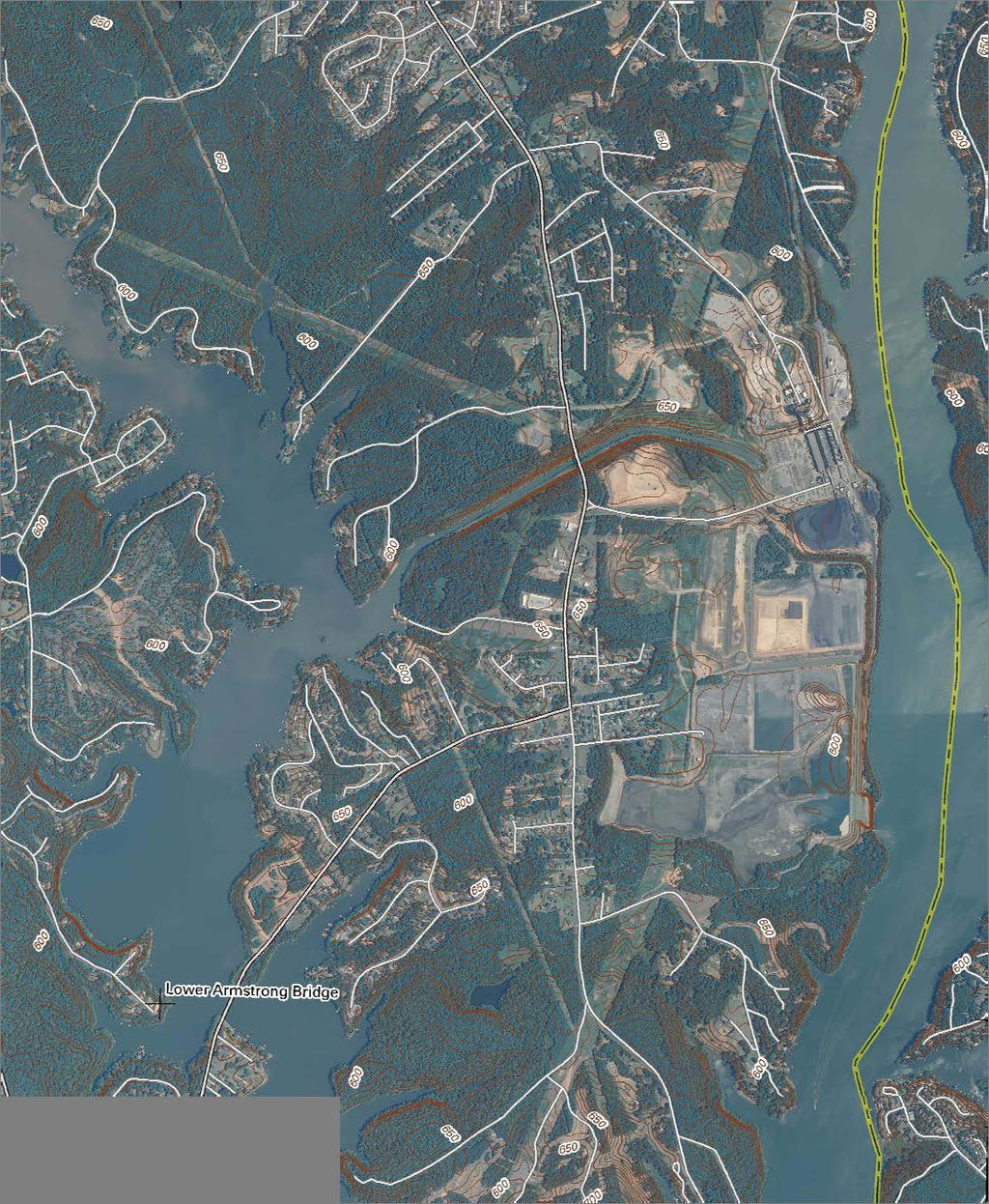
63
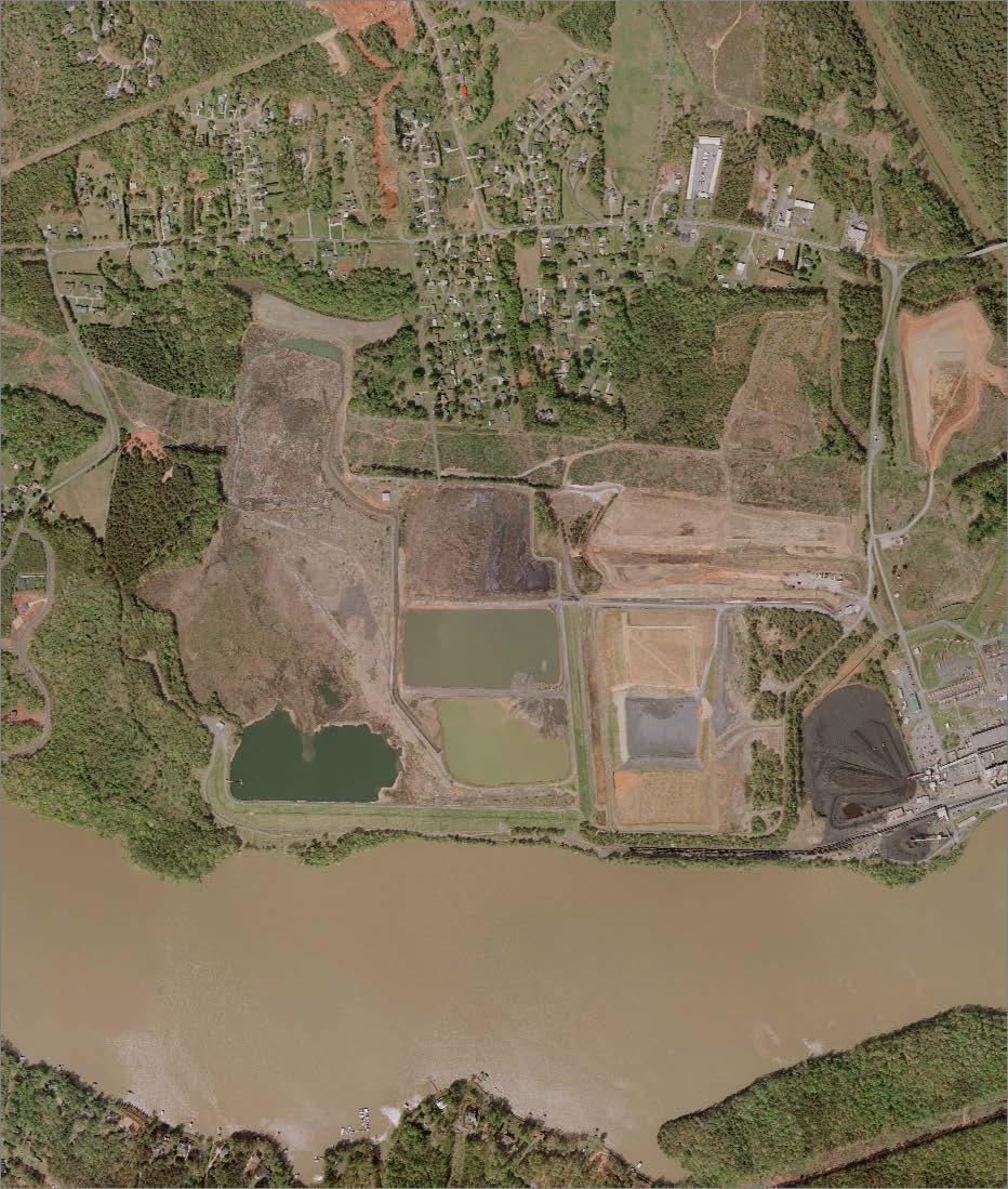
64

65
66 Tables
67 Table 1. Groundwater Monitoring Requirements Well Nomenclature Constituents and Parameters Frequency Antimony Chromium Nickel Thallium Monitoring Wells: AB-1R, AB-4S, Arsenic Copper Nitrate Water Level AB-4D, AB-9S*, AB-9D*, AB-10S*, Barium Iron ph Zinc March, July, AB-10D*, AB-11D, AB-12S, AB-12D, Boron Lead Selenium November AB-13S, AB-13D, AB-14D Cadmium Manganese Sulfate Chloride Mercury TDS Note: Monitoring wells marked with * are located inside of the compliance boundary. Table 2. Monitoring Well Locations Monitoring Well Locations At or Near the Compliance Boundary Inside of the Compliance Boundary Monitoring Well AB-1R, AB-4S, AB-4D, AB-11D, AB-12S, AB-12D, AB-13S, AB-13D, AB-14D AB-9S, AB-9D, AB-10S, AB-10D Tables - Page 1
68 Table 3. Exceedances of 2L Standards March 2011 November 2014 Parameter Boron Iron Manganese Nickel ph Units µg/l µg/l µg/l µg/l SU 2L Standard Well ID AB-1R AB-4S AB-4D No Exceedances No Exceedances No Exceedances 381 Range of Exceedances No Exceedances No Exceedances No Exceedances AB-9S ,600 10,500 9,320 10,200 AB-9D AB-10S AB-10D AB-11D AB-12S AB-12D AB-13S AB-13D AB-14D No Exceedances No Exceedances No Exceedances No Exceedances No Exceedances No Exceedances No Exceedances No Exceedances No Exceedances No Exceedances No Exceedances , No Exceedances No Exceedances No Exceedances No Exceedances No Exceedances No Exceedances No Exceedances No Exceedances No Exceedances No Exceedances No Exceedances No Exceedances , Tables - Page 2
69 Table 4. Environmental Exploration and Sampling Plan ALLEN STEAM STATION Exploration Area Active Ash Basin Inactive Ash Basin Beyond Waste Boundary Background Boring IDs AB-20 through AB-28, SB-7, SB-8, SB-9 AB-29 through AB-39, SB-1 through SB-6 Soil Borings Shallow Monitoring Wells Deep Monitoring Wells Bedrock Monitoring Wells Water Supply Well Surface Water/Seep Quantity Estimated Boring Depth (ft bgs) N/A 0 N/A BG-1, BG-2, and BG Well IDs AB-20S through AB-28S, AB-21SL, AB-24SL, and AB-25SL AB-29S through AB-39S, AB-29SL GWA-1S through GWA-9S BG-1S, BG-2S, and BG-3S Quantity Estimated Well Depth (ft bgs) Screen Length (ft) Well IDs AB-20D through AB-28D AB-29D through AB-39D GWA-1D through GWA-9D BG-1D, BG-2D, and BG-3D Quantity Estimated Casing Depth (ft bgs) Estimated Well Depth (ft bgs) Screen Length (ft) Well IDs Quantity Estimated Casing Depth (ft bgs) Estimated Well Depth (ft bgs) Screen Length (ft) Well ID Quantity Quantity of Locations N/A N/A N/A N/A N/A N/A N/A AB-35BR N/A N/A N/A N/A GWA-1BR, GWA-3BR, GWA-6BR Existing Water Supply Wells Quantity of Samples 2 9 Seeps BG-2BR N/A N/A N/A N/A Notes: 1. Estimated boring and well depths based on data available at the time of work plan preparation and subject to change based on site-specific conditions in the field. 2. Laboratory analyses of soil, ash, groundwater, and surface water samples will be performed in accordance with the constituents and methods identified in Tables 5 and Additionally, soils will be tested in the laboratory to determine grain size (with hydrometer), specific gravity, and permeability. 4. During drilling operations, downhole testing will be conducted to determine in-situ soil properties such as horizontal and vertical hydraulic conductivity. 5. Actual number of field and laboratory tests will be determined in field by Field Engineer or Geologist in accordance with project specifications. 6. Seep sample locations include both water and sediment samples. Tables - Page 3
70 Table 5. Soil and Ash Parameters and Constituent Analytical Methods INORGANIC COMPOUNDS UNITS METHOD Antimony mg/kg EPA 6020A Arsenic mg/kg EPA 6020A Barium mg/kg EPA 6010C Boron mg/kg EPA 6010C Cadmium mg/kg EPA 6020A Chloride mg/kg EPA 9056A Chromium mg/kg EPA 6010C Copper mg/kg EPA 6010C Iron mg/kg EPA 6010C Lead mg/kg EPA 6020A Manganese mg/kg EPA 6010C Mercury mg/kg EPA Method 7470A/7471B Nickel mg/kg EPA 6010C ph SU EPA 9045D Selenium mg/kg EPA 6020A Thallium (low level) (SPLP Extract only) mg/kg EPA 6020A Zinc mg/kg EPA 6010C Notes: 1. Soil samples to be analyzed for Total Inorganics using USEPA Methods 6010/6020 and ph using USEPA Method 9045, as noted above. 2. Ash samples to be analyzed for Total Inorganics using USEPA Methods 6010/6020 and ph using USEPA Method 9045; select ash samples will also be analyzed for leaching potential using SPLP Extraction Method 1312 in conjunction with USEPA Methods 6010/6020. SPLP results to be reported in units of mg/l for comparison to 2L Standards. Tables - Page 4
71 Table 6. Groundwater, Surface Water, and Seep Parameters and Constituent Analytical Methods PARAMETER RL UNITS METHOD FIELD PARAMETERS ph NA SU Field Water Quality Meter Specific Conductance NA mmho/cm Field Water Quality Meter Temperature NA ºC Field Water Quality Meter Dissolved Oxygen NA mg/l Field Water Quality Meter Oxidation Reduction Potential NA mv Field Water Quality Meter Turbidity NA NTU Field Water Quality Meter Ferrous Iron NA mg/l Field Test Kit INORGANICS Aluminum 5 µg/l EPA or 6010C Antimony 1 µg/l EPA or 6020A Arsenic 1 µg/l EPA or 6020A Barium 5 µg/l EPA or 6010C Beryllium 1 µg/l EPA or 6020A Boron 50 µg/l EPA or 6010C Cadmium 1 µg/l EPA or 6020A Chromium 1 µg/l EPA or 6010C Cobalt 1 µg/l EPA or 6020A Copper mg/l EPA or 6010C Iron 10 µg/l EPA or 6010C Lead 1 µg/l EPA or 6020A Manganese 5 µg/l EPA or 6010C Mercury (low level) µg/l EPA or 1631 Molybdenum 5 µg/l EPA or 6010C Nickel 5 µg/l EPA or 6010C Total Combined Radium (Ra-226 and Ra-228) 4 5 pci/l EPA Selenium 1 µg/l EPA or 6020A Strontium 5 µg/l EPA or 6010C Thallium (low level) 0.2 µg/l EPA or 6020A Vanadium (low level) 0.3 mg/l EPA or 6020A Zinc 5 µg/l EPA or 6010C ANIONS/CATIONS Alkalinity (as CaCO3) 20 mg/l SM 2320B Bicarbonate 20 mg/l SM 2320 Calcium 0.01 mg/l EPA Carbonate 20 mg/l SM 2320 Chloride 0.1 mg/l EPA or 9056A Magnesium mg/l EPA Nitrate as Nitrogen mg-n/l EPA or 9056A Potassium 0.1 mg/l EPA Sodium 0.05 mg/l EPA Sulfate 0.1 mg/l EPA or 9056A Sulfide (as H 2S) mg/l SM4500S-D Total Dissolved Solids 25 mg/l SM 2540C Total Organic Carbon 0.1 mg/l SM 5310 Total Suspended Solids 2 mg/l SM 2450D ADDITIONAL GROUNDWATER CONSTITUENTS Iron Speciation (Fe(II),Fe(III) Vendor Specific µg/l IC-ICP-CRC-MS Manganese Speciation (Mn(II), Mn(III), Mn(IV)) Vendor Specific µg/l IC-ICP-CRC-MS Notes: 1. Select constituents will be analyzed for total and dissolved concentrations. 2. RL is the laboratory analytical method reporting limit. 3. NA indicates not applicable. 4. Voluntary monitoring well AB-8D and the proposed background wells BG-3S/D will be sampled for total combined radium. 5. Sulfide (as H 2S) will be analyzed for groundwater samples only. 6. Select wells will be sampled for iron and manganese speciation as described in Section of the work plan. 7. All EPA methods and RLs are at or below the respective 2L or 2B Standard for constituents with standards. Tables - Page 5 1
72 Table 7. Historical groundwater analytical results (compliance and voluntary monitoring wells) Analytical Parameter Depth to Water Temp. DO Cond. ph ORP Turbidity Alkalinity Aluminum Antimony Arsenic Barium Beryllium Boron Cadmium Units Feet C mg/l µmhos/cm SU mv NTU mg/l CaCO 3 mg/l µg/l µg/l µg/l µg/l µg/l µg/l 15A NCAC 02L.0202(g) Groundwater Quality Standard NA NA NA NA NA NA NE NE 1* * Analytical Method 2320B4d Well Name Well Type Hydrostratigraphic Unit Sample Collection Date Field Measurements Total Total Dissolved Total Dissolved Total Dissolved Total Total Dissolved Total Dissolved Total AB-1 Compliance Transition (Saprolite) 11/2/2004 N/A 18 N/A N/A 97 N/A N/A N/A N/A N/A <2 N/A 36 N/A N/A N/A N/A <0.5 AB-1 Compliance Transition (Saprolite) 5/2/2005 N/A 15 N/A N/A N/A N/A N/A N/A N/A N/A <2 N/A 48 N/A N/A N/A N/A <0.5 AB-1 Compliance Transition (Saprolite) 11/16/2005 N/A N/A N/A 76.6 N/A N/A N/A N/A N/A <2 N/A 26 N/A N/A <100 N/A <0.5 AB-1 Compliance Transition (Saprolite) 5/8/2006 N/A N/A N/A 88.2 N/A N/A N/A N/A N/A <2 N/A 66 N/A N/A <100 N/A <0.5 AB-1 Compliance Transition (Saprolite) 11/13/2006 N/A N/A N/A 211 N/A N/A N/A N/A N/A <2 N/A 46 N/A N/A <100 N/A <0.5 AB-1 Compliance Transition (Saprolite) 5/14/2007 N/A N/A N/A 95.1 N/A N/A N/A N/A N/A <2 N/A 22 N/A N/A <100 N/A <0.5 AB-1 Compliance Transition (Saprolite) 11/7/2007 N/A N/A N/A 73.4 N/A N/A N/A N/A N/A <2 N/A 31 N/A N/A <100 N/A <0.5 AB-1 Compliance Transition (Saprolite) 5/14/2008 N/A 14.9 N/A N/A 19.7 N/A N/A N/A N/A N/A <2 N/A 33 N/A N/A <100 N/A <0.5 AB-1 Compliance Transition (Saprolite) 5/4/ N/A N/A 640 N/A N/A N/A N/A N/A <1 N/A 132 N/A N/A <50 N/A <1 AB-10D Compliance Bedrock 3/1/ N/A N/A 55.7 N/A N/A N/A <1 N/A <1 N/A 37 N/A N/A <50 N/A <1 AB-10D Compliance Bedrock 7/7/ N/A N/A 13.6 N/A N/A N/A <1 N/A <1 N/A 33 N/A N/A <50 N/A <1 AB-10D Compliance Bedrock 11/1/ N/A N/A 7.4 N/A N/A N/A <1 N/A <1 N/A 32 N/A N/A <50 N/A <1 AB-10D Compliance Bedrock 3/5/ N/A N/A N/A <1 N/A <1 N/A 33 N/A N/A <50 N/A <1 AB-10D Compliance Bedrock 7/5/ N/A N/A N/A <1 N/A <1 N/A 34 N/A N/A <50 N/A <1 AB-10D Compliance Bedrock 11/5/ <5 N/A N/A <1 N/A <1 N/A 33 N/A N/A <50 N/A <1 AB-10D Compliance Bedrock 3/4/ N/A N/A N/A <1 N/A <1 N/A 33 N/A N/A <50 N/A <1 AB-10D Compliance Bedrock 7/1/ N/A N/A <1 <1 <1 < N/A <50 <50 <1 <1 AB-10D Compliance Bedrock 11/6/ N/A N/A N/A <1 N/A <1 N/A 36 N/A N/A <50 N/A <1 AB-10D Compliance Bedrock 3/5/ N/A N/A N/A <1 N/A <1 N/A 36 N/A N/A <50 N/A <1 AB-10D Compliance Bedrock 7/7/ N/A N/A N/A <1 N/A <1 N/A 39 N/A N/A <50 N/A <1 AB-10D Compliance Bedrock 11/4/ N/A N/A N/A N/A N/A N/A N/A N/A N/A N/A N/A N/A N/A AB-10S Compliance Residuum 3/1/ N/A N/A 11 N/A N/A N/A <1 N/A <1 N/A 38 N/A N/A <50 N/A <1 AB-10S Compliance Residuum 7/7/ N/A N/A 1.46 N/A N/A N/A <1 N/A <1 N/A 37 N/A N/A <50 N/A <1 AB-10S Compliance Residuum 11/1/ N/A N/A 23.6 N/A N/A N/A <1 N/A <1 N/A 43 N/A N/A <50 N/A <1 AB-10S Compliance Residuum 3/5/ N/A N/A N/A <1 N/A <1 N/A 43 N/A N/A <50 N/A <1 AB-10S Compliance Residuum 7/5/ N/A N/A N/A <1 N/A <1 N/A 44 N/A N/A <50 N/A <1 AB-10S Compliance Residuum 11/5/ <5 N/A N/A <1 N/A <1 N/A 47 N/A N/A <50 N/A <1 AB-10S Compliance Residuum 3/4/ N/A N/A N/A <1 N/A <1 N/A 45 N/A N/A <50 N/A <1 AB-10S Compliance Residuum 7/1/ N/A N/A <1 <1 <1 < N/A <50 <50 <1 <1 AB-10S Compliance Residuum 11/6/ N/A N/A N/A <1 N/A <1 N/A 53 N/A N/A <50 N/A <1 AB-10S Compliance Residuum 3/5/ N/A N/A N/A <1 N/A <1 N/A 52 N/A N/A <50 N/A <1 AB-10S Compliance Residuum 7/7/ N/A N/A N/A <1 N/A <1 N/A 53 N/A N/A <50 N/A <1 AB-10S Compliance Residuum 11/4/ N/A N/A N/A N/A N/A N/A N/A N/A N/A N/A N/A N/A N/A AB-11D Compliance Bedrock 3/1/ N/A N/A 21.2 N/A N/A N/A <1 N/A <1 N/A 41 N/A N/A <50 N/A <1 AB-11D Compliance Bedrock 7/7/ N/A N/A 17.4 N/A N/A N/A <1 N/A <1 N/A 40 N/A N/A <50 N/A <1 AB-11D Compliance Bedrock 11/1/ N/A N/A 17.6 N/A N/A N/A <1 N/A <1 N/A 40 N/A N/A <50 N/A <1 AB-11D Compliance Bedrock 3/5/ N/A N/A N/A <1 N/A <1 N/A 40 N/A N/A <50 N/A <1 AB-11D Compliance Bedrock 7/5/ N/A N/A N/A <1 N/A <1 N/A 47 N/A N/A <50 N/A <1 AB-11D Compliance Bedrock 11/5/ <5 N/A N/A <1 N/A <1 N/A 44 N/A N/A <50 N/A <1 AB-11D Compliance Bedrock 3/5/ N/A N/A N/A <1 N/A <1 N/A 42 N/A N/A <50 N/A <1 AB-11D Compliance Bedrock 7/2/ N/A N/A <1 <1 <1 < N/A <50 <50 <1 <1 AB-11D Compliance Bedrock 11/6/ N/A N/A N/A <1 N/A <1 N/A 45 N/A N/A <50 N/A <1 AB-11D Compliance Bedrock 3/5/ N/A N/A N/A <1 N/A <1 N/A 44 N/A N/A <50 N/A <1 AB-11D Compliance Bedrock 7/7/ N/A N/A N/A <1 N/A <1 N/A 43 N/A N/A <50 N/A <1 AB-11D Compliance Bedrock 11/4/ N/A N/A N/A N/A N/A N/A N/A N/A N/A N/A N/A N/A N/A AB-12D Compliance Bedrock 3/1/ N/A N/A 7.6 N/A N/A N/A <1 N/A <1 N/A 57 N/A N/A <50 N/A <1 AB-12D Compliance Bedrock 7/7/ N/A N/A 6.91 N/A N/A N/A <1 N/A <1 N/A 48 N/A N/A <50 N/A <1 AB-12D Compliance Bedrock 11/1/ N/A N/A 8.64 N/A N/A N/A <1 N/A <1 N/A 48 N/A N/A <50 N/A <1 AB-12D Compliance Bedrock 3/5/ N/A N/A N/A <1 N/A <1 N/A 46 N/A N/A <50 N/A <1 AB-12D Compliance Bedrock 7/5/ N/A N/A N/A <1 N/A <1 N/A 47 N/A N/A <50 N/A <1 AB-12D Compliance Bedrock 11/5/ <5 N/A N/A <1 N/A <1 N/A 47 N/A N/A <50 N/A <1 AB-12D Compliance Bedrock 3/5/ N/A N/A N/A <1 N/A <1 N/A 48 N/A N/A <50 N/A <1 AB-12D Compliance Bedrock 7/2/ N/A N/A <1 <1 <1 < N/A <50 <50 <1 <1 AB-12D Compliance Bedrock 11/6/ N/A N/A N/A <1 N/A <1 N/A 49 N/A N/A <50 N/A <1 AB-12D Compliance Bedrock 3/5/ N/A N/A N/A <1 N/A <1 N/A 47 N/A N/A <50 N/A <1 AB-12D Compliance Bedrock 7/7/ N/A N/A N/A <1 N/A <1 N/A 45 N/A N/A <50 N/A <1 AB-12D Compliance Bedrock 11/4/ N/A N/A N/A N/A N/A N/A N/A N/A N/A N/A N/A N/A N/A AB-12S Compliance Residuum 3/1/ N/A N/A 2.63 N/A N/A N/A <1 N/A <1 N/A 31 N/A N/A <50 N/A <1 AB-12S Compliance Residuum 7/7/ N/A N/A 6.29 N/A N/A N/A <1 N/A <1 N/A 34 N/A N/A <50 N/A <1 Tables - Page 6
73 Table 7. Historical groundwater analytical results (compliance and voluntary monitoring wells) Analytical Parameter Depth to Water Temp. DO Cond. ph ORP Turbidity Alkalinity Aluminum Antimony Arsenic Barium Beryllium Boron Cadmium Units Feet C mg/l µmhos/cm SU mv NTU mg/l CaCO 3 mg/l µg/l µg/l µg/l µg/l µg/l µg/l 15A NCAC 02L.0202(g) Groundwater Quality Standard NA NA NA NA NA NA NE NE 1* * Analytical Method 2320B4d Well Name Well Type Hydrostratigraphic Unit Sample Collection Date Field Measurements Total Total Dissolved Total Dissolved Total Dissolved Total Total Dissolved Total Dissolved Total AB-12S Compliance Residuum 11/1/ N/A N/A 7.99 N/A N/A N/A <1 N/A <1 N/A 34 N/A N/A <50 N/A <1 AB-12S Compliance Residuum 3/5/ N/A N/A N/A <1 N/A <1 N/A 37 N/A N/A <50 N/A <1 AB-12S Compliance Residuum 7/5/ N/A N/A N/A <1 N/A <1 N/A 35 N/A N/A <50 N/A <1 AB-12S Compliance Residuum 11/5/ <5 N/A N/A <1 N/A <1 N/A 37 N/A N/A <50 N/A <1 AB-12S Compliance Residuum 3/5/ N/A N/A N/A <1 N/A <1 N/A 34 N/A N/A <50 N/A <1 AB-12S Compliance Residuum 7/2/ N/A N/A <1 <1 <1 < N/A <50 <50 <1 <1 AB-12S Compliance Residuum 11/6/ N/A N/A N/A <1 N/A <1 N/A 38 N/A N/A <50 N/A <1 AB-12S Compliance Residuum 3/5/ N/A N/A N/A <1 N/A <1 N/A 38 N/A N/A <50 N/A <1 AB-12S Compliance Residuum 7/7/ N/A N/A N/A <1 N/A <1 N/A 40 N/A N/A <50 N/A <1 AB-12S Compliance Residuum 11/4/ N/A N/A N/A N/A N/A N/A N/A N/A N/A N/A N/A N/A N/A AB-13D Compliance Bedrock 3/1/ N/A N/A 30.1 N/A N/A N/A <1 N/A <1 N/A 68 N/A N/A <50 N/A <1 AB-13D Compliance Bedrock 7/7/ N/A N/A 11 N/A N/A N/A <1 N/A <1 N/A 51 N/A N/A <50 N/A <1 AB-13D Compliance Bedrock 11/1/ N/A N/A 23.1 N/A N/A N/A <1 N/A <1 N/A 50 N/A N/A <50 N/A <1 AB-13D Compliance Bedrock 3/5/ N/A N/A N/A <1 N/A <1 N/A 75 N/A N/A <50 N/A <1 AB-13D Compliance Bedrock 7/5/ N/A N/A N/A <1 N/A <1 N/A 86 N/A N/A <50 N/A <1 AB-13D Compliance Bedrock 11/5/ N/A N/A 169 <5 N/A N/A <1 N/A <1 N/A 116 N/A N/A <50 N/A <1 AB-13D Compliance Bedrock 3/4/ N/A N/A N/A <1 N/A <1 N/A 48 N/A N/A <50 N/A <1 AB-13D Compliance Bedrock 7/1/ N/A N/A <1 <1 <1 < N/A <50 <50 <1 <1 AB-13D Compliance Bedrock 11/7/ N/A N/A N/A <1 N/A <1 N/A 40 N/A N/A <50 N/A <1 AB-13D Compliance Bedrock 3/5/ N/A N/A N/A <1 N/A <1 N/A 47 N/A N/A <50 N/A <1 AB-13D Compliance Bedrock 7/7/ N/A N/A N/A <1 N/A <1 N/A 46 N/A N/A <50 N/A <1 AB-13D Compliance Bedrock 11/4/ N/A N/A N/A N/A N/A N/A N/A N/A N/A N/A N/A N/A N/A AB-13S Compliance Residuum 3/1/ N/A N/A 20.3 N/A N/A N/A <1 N/A <1 N/A 26 N/A N/A <50 N/A <1 AB-13S Compliance Residuum 7/7/ N/A N/A 2.5 N/A N/A N/A <1 N/A <1 N/A 22 N/A N/A <50 N/A <1 AB-13S Compliance Residuum 11/1/ N/A N/A 7.46 N/A N/A N/A <1 N/A <1 N/A 24 N/A N/A <50 N/A <1 AB-13S Compliance Residuum 3/5/ N/A N/A N/A <1 N/A <1 N/A 27 N/A N/A <50 N/A <1 AB-13S Compliance Residuum 7/5/ N/A N/A N/A <1 N/A <1 N/A 30 N/A N/A <50 N/A <1 AB-13S Compliance Residuum 11/5/ N/A N/A 3.7 <5 N/A N/A <1 N/A <1 N/A 31 N/A N/A <50 N/A <1 AB-13S Compliance Residuum 3/4/ N/A N/A N/A <1 N/A <1 N/A 39 N/A N/A <50 N/A <1 AB-13S Compliance Residuum 7/1/ N/A N/A <1 <1 <1 < N/A <50 <50 <1 <1 AB-13S Compliance Residuum 11/7/ N/A N/A N/A <1 N/A <1 N/A 30 N/A N/A <50 N/A <1 AB-13S Compliance Residuum 3/5/ N/A N/A N/A <1 N/A <1 N/A 38 N/A N/A <50 N/A <1 AB-13S Compliance Residuum 7/7/ N/A N/A N/A <1 N/A <1 N/A 36 N/A N/A <50 N/A <1 AB-13S Compliance Residuum 11/4/ N/A N/A N/A N/A N/A N/A N/A N/A N/A N/A N/A N/A N/A AB-14D Compliance Bedrock 3/1/ N/A N/A 12.7 N/A N/A N/A <1 N/A <1 N/A 117 N/A N/A <50 N/A <1 AB-14D Compliance Bedrock 7/21/ N/A N/A 3.83 N/A N/A N/A <1 N/A <1 N/A 149 N/A N/A 59 N/A <1 AB-14D Compliance Bedrock 11/1/ N/A N/A 10.4 N/A N/A N/A <1 N/A <1 N/A 136 N/A N/A 85 N/A <1 AB-14D Compliance Bedrock 3/5/ N/A N/A N/A <1 N/A <1 N/A 97 N/A N/A 116 N/A <1 AB-14D Compliance Bedrock 7/5/ N/A N/A N/A <1 N/A <1 N/A 84 N/A N/A 57 N/A <1 AB-14D Compliance Bedrock 11/5/ <5 N/A N/A <1 N/A <1 N/A 80 N/A N/A 84 N/A <1 AB-14D Compliance Bedrock 3/5/ N/A N/A N/A <1 N/A <1 N/A 82 N/A N/A 111 N/A <1 AB-14D Compliance Bedrock 7/2/ N/A N/A <1 <1 <1 < N/A <1 <1 AB-14D Compliance Bedrock 11/7/ N/A N/A N/A <1 N/A <1 N/A 76 N/A N/A 65 N/A <1 AB-14D Compliance Bedrock 3/5/ N/A N/A N/A <1 N/A <1 N/A 80 N/A N/A 109 N/A <1 AB-14D Compliance Bedrock 7/7/ N/A N/A N/A <1 N/A <1 N/A 73 N/A N/A 82 N/A <1 AB-14D Compliance Bedrock 11/4/ N/A N/A N/A N/A N/A N/A N/A N/A N/A N/A N/A N/A N/A AB-1R Compliance Transition (Saprolite) 3/1/ N/A N/A 3.73 N/A N/A N/A <1 N/A <1 N/A 57 N/A N/A <50 N/A <1 AB-1R Compliance Transition (Saprolite) 7/7/ N/A N/A 6.35 N/A N/A N/A <1 N/A <1 N/A 51 N/A N/A <50 N/A <1 AB-1R Compliance Transition (Saprolite) 11/1/ N/A N/A 9.18 N/A N/A N/A <1 N/A <1 N/A 49 N/A N/A <50 N/A <1 AB-1R Compliance Transition (Saprolite) 3/5/ N/A N/A N/A <1 N/A <1 N/A 42 N/A N/A <50 N/A <1 AB-1R Compliance Transition (Saprolite) 7/5/ N/A N/A N/A <1 N/A <1 N/A 41 N/A N/A <50 N/A <1 AB-1R Compliance Transition (Saprolite) 11/5/ <5 N/A N/A <1 N/A <1 N/A 41 N/A N/A <50 N/A <1 AB-1R Compliance Transition (Saprolite) 3/4/ N/A N/A N/A <1 N/A <1 N/A 37 N/A N/A <50 N/A <1 AB-1R Compliance Transition (Saprolite) 7/1/ N/A N/A <1 <1 <1 < N/A <50 <50 <1 <1 AB-1R Compliance Transition (Saprolite) 11/7/ N/A N/A N/A <1 N/A <1 N/A 39 N/A N/A <50 N/A <1 AB-1R Compliance Transition (Saprolite) 3/5/ N/A N/A N/A <1 N/A <1 N/A 41 N/A N/A <50 N/A <1 AB-1R Compliance Transition (Saprolite) 7/7/ N/A N/A N/A <1 N/A <1 N/A 73 N/A N/A <50 N/A <1 AB-1R Compliance Transition (Saprolite) 11/4/ N/A N/A N/A N/A N/A N/A N/A N/A N/A N/A N/A N/A N/A AB-2 Voluntary Transition (Saprolite) 11/2/2004 N/A 16 N/A 32 5 N/A 44 N/A N/A N/A N/A N/A <2 N/A 35 N/A N/A N/A N/A 0.55 Tables - Page 7
74 Table 7. Historical groundwater analytical results (compliance and voluntary monitoring wells) Analytical Parameter Depth to Water Temp. DO Cond. ph ORP Turbidity Alkalinity Aluminum Antimony Arsenic Barium Beryllium Boron Cadmium Units Feet C mg/l µmhos/cm SU mv NTU mg/l CaCO 3 mg/l µg/l µg/l µg/l µg/l µg/l µg/l 15A NCAC 02L.0202(g) Groundwater Quality Standard NA NA NA NA NA NA NE NE 1* * Analytical Method 2320B4d Well Name Well Type Hydrostratigraphic Unit Sample Collection Date Field Measurements Total Total Dissolved Total Dissolved Total Dissolved Total Total Dissolved Total Dissolved Total AB-2 Voluntary Transition (Saprolite) 5/2/2005 N/A 14 N/A N/A N/A N/A N/A N/A N/A N/A <2 N/A 41 N/A N/A N/A N/A <0.5 AB-2 Voluntary Transition (Saprolite) 11/16/2005 N/A N/A N/A 28.4 N/A N/A N/A N/A N/A <2 N/A 35 N/A N/A <100 N/A <0.5 AB-2 Voluntary Transition (Saprolite) 5/8/2006 N/A N/A N/A 24.7 N/A N/A N/A N/A N/A <2 N/A 37 N/A N/A <100 N/A <0.5 AB-2 Voluntary Transition (Saprolite) 11/13/2006 N/A N/A N/A 12.7 N/A N/A N/A N/A N/A <2 N/A 35 N/A N/A <100 N/A <0.5 AB-2 Voluntary Transition (Saprolite) 5/14/2007 N/A N/A N/A 5.45 N/A N/A N/A N/A N/A <2 N/A 30 N/A N/A <100 N/A <0.5 AB-2 Voluntary Transition (Saprolite) 11/7/2007 N/A N/A 25 5 N/A 7.94 N/A N/A N/A N/A N/A <2 N/A 32 N/A N/A <100 N/A <0.5 AB-2 Voluntary Transition (Saprolite) 5/14/2008 N/A 14.3 N/A N/A 11.7 N/A N/A N/A N/A N/A <2 N/A 38 N/A N/A <100 N/A <0.5 AB-2 Voluntary Transition (Saprolite) 11/3/2008 N/A N/A N/A 28.8 N/A N/A N/A N/A N/A <2 N/A 19 N/A N/A <100 N/A <0.5 AB-2 Voluntary Transition (Saprolite) 5/13/2009 N/A N/A N/A 19.8 N/A N/A N/A N/A N/A <1 N/A 13 N/A N/A <100 N/A <0.5 AB-2 Voluntary Transition (Saprolite) 11/3/2009 N/A N/A N/A 5.88 N/A N/A N/A N/A N/A <1 N/A 18 N/A N/A <50 N/A <1 AB-2 Voluntary Transition (Saprolite) 5/4/ N/A N/A 7.89 N/A N/A N/A N/A N/A <1 N/A 17.2 N/A N/A <50 N/A <1 AB-2 Voluntary Transition (Saprolite) 3/1/ N/A N/A N/A N/A N/A N/A N/A N/A N/A N/A N/A N/A N/A N/A N/A N/A N/A N/A N/A AB-2D Voluntary Partially Weathered Rock 11/2/2004 N/A 16 N/A N/A 7.2 N/A N/A N/A N/A N/A <2 N/A 34 N/A N/A N/A N/A <0.5 AB-2D Voluntary Partially Weathered Rock 5/2/2005 N/A 15 N/A N/A N/A N/A N/A N/A N/A N/A <2 N/A 34 N/A N/A N/A N/A <0.5 AB-2D Voluntary Partially Weathered Rock 11/16/2005 N/A N/A N/A 15.8 N/A N/A N/A N/A N/A <2 N/A 29 N/A N/A <100 N/A <0.5 AB-2D Voluntary Partially Weathered Rock 5/8/2006 N/A N/A N/A 17.3 N/A N/A N/A N/A N/A <2 N/A 34 N/A N/A <100 N/A <0.5 AB-2D Voluntary Partially Weathered Rock 11/13/2006 N/A N/A N/A 5.81 N/A N/A N/A N/A N/A <2 N/A 32 N/A N/A <100 N/A <0.5 AB-2D Voluntary Partially Weathered Rock 5/14/2007 N/A N/A N/A 0.63 N/A N/A N/A N/A N/A <2 N/A 26 N/A N/A <100 N/A <0.5 AB-2D Voluntary Partially Weathered Rock 11/7/2007 N/A N/A N/A 1.01 N/A N/A N/A N/A N/A <2 N/A 28 N/A N/A <100 N/A <0.5 AB-2D Voluntary Partially Weathered Rock 5/14/2008 N/A N/A N/A 4.63 N/A N/A N/A N/A N/A <2 N/A 29 N/A N/A <100 N/A <0.5 AB-2D Voluntary Partially Weathered Rock 11/3/2008 N/A N/A N/A 1.07 N/A N/A N/A N/A N/A <2 N/A 30 N/A N/A <100 N/A <0.5 AB-2D Voluntary Partially Weathered Rock 5/13/2009 N/A N/A N/A 2.01 N/A N/A N/A N/A N/A <1 N/A 31 N/A N/A <100 N/A <0.5 AB-2D Voluntary Partially Weathered Rock 11/3/2009 N/A N/A N/A 2.5 N/A N/A N/A N/A N/A <1 N/A 29.6 N/A N/A <50 N/A <1 AB-2D Voluntary Partially Weathered Rock 5/4/ N/A N/A 1.46 N/A N/A N/A N/A N/A <2 N/A 29.6 N/A N/A <50 N/A <1 AB-2D Voluntary Partially Weathered Rock 3/1/ N/A N/A N/A N/A N/A N/A N/A N/A N/A N/A N/A N/A N/A N/A N/A N/A N/A N/A N/A AB-4D Compliance Partially Weathered Rock 11/2/2004 N/A 17 N/A N/A 14 N/A N/A N/A N/A N/A <2 N/A 33 N/A N/A N/A N/A <0.5 AB-4D Compliance Partially Weathered Rock 5/2/2005 N/A 16 N/A N/A N/A N/A N/A N/A N/A N/A <2 N/A 27 N/A N/A N/A N/A <0.5 AB-4D Compliance Partially Weathered Rock 11/16/2005 N/A N/A N/A 14.8 N/A N/A N/A N/A N/A <2 N/A 23 N/A N/A <100 N/A <0.5 AB-4D Compliance Partially Weathered Rock 5/8/2006 N/A N/A N/A 18.8 N/A N/A N/A N/A N/A <2 N/A 27 N/A N/A <100 N/A <0.5 AB-4D Compliance Partially Weathered Rock 11/13/2006 N/A 16.8 N/A N/A 9.64 N/A N/A N/A N/A N/A <2 N/A 28 N/A N/A <100 N/A <0.5 AB-4D Compliance Partially Weathered Rock 5/14/2007 N/A N/A N/A 0.55 N/A N/A N/A N/A N/A <2 N/A 22 N/A N/A <100 N/A <0.5 AB-4D Compliance Partially Weathered Rock 11/7/2007 N/A 16.7 N/A N/A 0.67 N/A N/A N/A N/A N/A <2 N/A 23 N/A N/A <100 N/A <0.5 AB-4D Compliance Partially Weathered Rock 5/14/2008 N/A N/A N/A 4.39 N/A N/A N/A N/A N/A <2 N/A 24 N/A N/A <100 N/A <0.5 AB-4D Compliance Partially Weathered Rock 11/3/2008 N/A N/A N/A 1.36 N/A N/A N/A N/A N/A <2 N/A 25 N/A N/A <100 N/A <0.5 AB-4D Compliance Partially Weathered Rock 5/13/2009 N/A N/A N/A 1.94 N/A N/A N/A N/A N/A <1 N/A 26 N/A N/A <100 N/A <0.5 AB-4D Compliance Partially Weathered Rock 11/3/2009 N/A N/A N/A 3.32 N/A N/A N/A N/A N/A <1 N/A 23.6 N/A N/A <50 N/A <1 AB-4D Compliance Partially Weathered Rock 5/4/ N/A N/A 2.09 N/A N/A N/A N/A N/A <1 N/A 25.5 N/A N/A <50 N/A <1 AB-4D Compliance Partially Weathered Rock 3/1/ N/A N/A 0.27 N/A N/A N/A <1 N/A <1 N/A 26 N/A N/A <50 N/A <1 AB-4D Compliance Partially Weathered Rock 7/7/ N/A N/A 6.12 N/A N/A N/A <1 N/A <1 N/A 25 N/A N/A <50 N/A <1 AB-4D Compliance Partially Weathered Rock 11/1/ N/A N/A 4.1 N/A N/A N/A <1 N/A <1 N/A 25 N/A N/A <50 N/A <1 AB-4D Compliance Partially Weathered Rock 3/5/ N/A N/A N/A <1 N/A <1 N/A 25 N/A N/A <50 N/A <1 AB-4D Compliance Partially Weathered Rock 7/5/ N/A N/A N/A <1 N/A <1 N/A 26 N/A N/A <50 N/A <1 AB-4D Compliance Partially Weathered Rock 11/5/ N/A N/A 0.52 <5 N/A N/A <1 N/A <1 N/A 27 N/A N/A <50 N/A <1 AB-4D Compliance Partially Weathered Rock 3/5/ N/A N/A N/A <1 N/A <1 N/A 29 N/A N/A <50 N/A <1 AB-4D Compliance Partially Weathered Rock 7/2/ N/A N/A <1 <1 <1 < N/A <50 <50 <1 <1 AB-4D Compliance Partially Weathered Rock 11/6/ N/A N/A N/A <1 N/A <1 N/A 30 N/A N/A <50 N/A <1 AB-4D Compliance Partially Weathered Rock 3/5/ N/A N/A N/A <1 N/A <1 N/A 27 N/A N/A <50 N/A <1 AB-4D Compliance Partially Weathered Rock 7/7/ N/A N/A N/A <1 N/A <1 N/A 30 N/A N/A <50 N/A <1 AB-4D Compliance Partially Weathered Rock 11/4/ N/A N/A N/A N/A N/A N/A N/A N/A N/A N/A N/A N/A N/A AB-4S (4) Compliance Transition (Saprolite) 11/2/2004 N/A 17 N/A N/A 147 N/A N/A N/A N/A N/A <2 N/A 55 N/A N/A N/A N/A <0.5 AB-4S (4) Compliance Transition (Saprolite) 5/2/2005 N/A 15 N/A N/A N/A N/A N/A N/A N/A N/A <2 N/A 100 N/A N/A N/A N/A <0.5 AB-4S (4) Compliance Transition (Saprolite) 11/16/2005 N/A N/A N/A 39.9 N/A N/A N/A N/A N/A <2 N/A 46 N/A N/A <100 N/A <0.5 AB-4S (4) Compliance Transition (Saprolite) 5/8/2006 N/A 14.8 N/A N/A 72.2 N/A N/A N/A N/A N/A <2 N/A 58 N/A N/A <100 N/A <0.5 AB-4S (4) Compliance Transition (Saprolite) 11/13/2006 N/A N/A N/A 58.2 N/A N/A N/A N/A N/A <2 N/A 69 N/A N/A <100 N/A <0.5 AB-4S (4) Compliance Transition (Saprolite) 5/14/2007 N/A N/A N/A 19.1 N/A N/A N/A N/A N/A <2 N/A 51 N/A N/A <100 N/A <0.5 AB-4S (4) Compliance Transition (Saprolite) 11/7/2007 N/A N/A N/A 40.6 N/A N/A N/A N/A N/A <2 N/A 59 N/A N/A <100 N/A <0.5 AB-4S (4) Compliance Transition (Saprolite) 5/14/2008 N/A N/A N/A 60.6 N/A N/A N/A N/A N/A <2 N/A 55 N/A N/A <100 N/A <0.5 AB-4S (4) Compliance Transition (Saprolite) 11/3/2008 N/A N/A N/A 24.4 N/A N/A N/A N/A N/A <2 N/A 51 N/A N/A <100 N/A <0.5 AB-4S (4) Compliance Transition (Saprolite) 5/13/2009 N/A 15.1 N/A N/A 12.7 N/A N/A N/A N/A N/A <1 N/A 39 N/A N/A <100 N/A <0.5 Tables - Page 8
75 Table 7. Historical groundwater analytical results (compliance and voluntary monitoring wells) Analytical Parameter Depth to Water Temp. DO Cond. ph ORP Turbidity Alkalinity Aluminum Antimony Arsenic Barium Beryllium Boron Cadmium Units Feet C mg/l µmhos/cm SU mv NTU mg/l CaCO 3 mg/l µg/l µg/l µg/l µg/l µg/l µg/l 15A NCAC 02L.0202(g) Groundwater Quality Standard NA NA NA NA NA NA NE NE 1* * Analytical Method 2320B4d Well Name Well Type Hydrostratigraphic Unit Sample Collection Date Field Measurements Total Total Dissolved Total Dissolved Total Dissolved Total Total Dissolved Total Dissolved Total AB-4S (4) Compliance Transition (Saprolite) 11/3/2009 N/A N/A N/A 15.3 N/A N/A N/A N/A N/A <1 N/A 37.3 N/A N/A <50 N/A <1 AB-4S (4) Compliance Transition (Saprolite) 5/4/ N/A N/A 7.71 N/A N/A N/A N/A N/A <2 N/A 31.1 N/A N/A <50 N/A <1 AB-4S (4) Compliance Transition (Saprolite) 3/1/ N/A N/A 9.46 N/A N/A N/A <1 N/A <1 N/A 33 N/A N/A <50 N/A <1 AB-4S (4) Compliance Transition (Saprolite) 7/7/ N/A N/A 16.9 N/A N/A N/A <1 N/A <1 N/A 33 N/A N/A <50 N/A <1 AB-4S (4) Compliance Transition (Saprolite) 11/1/ N/A N/A 11.2 N/A N/A N/A <1 N/A <1 N/A 37 N/A N/A <50 N/A <1 AB-4S (4) Compliance Transition (Saprolite) 3/5/ N/A N/A N/A <1 N/A <1 N/A 34 N/A N/A <50 N/A <1 AB-4S (4) Compliance Transition (Saprolite) 7/5/ N/A N/A N/A <1 N/A <1 N/A 31 N/A N/A <50 N/A <1 AB-4S (4) Compliance Transition (Saprolite) 11/5/ N/A N/A 4.71 <5 N/A N/A <1 N/A <1 N/A 35 N/A N/A <50 N/A <1 AB-4S (4) Compliance Transition (Saprolite) 3/5/ N/A N/A N/A <1 N/A <1 N/A 32 N/A N/A <50 N/A <1 AB-4S (4) Compliance Transition (Saprolite) 7/2/ N/A N/A <1 <1 <1 < N/A <50 <50 <1 <1 AB-4S (4) Compliance Transition (Saprolite) 11/6/ N/A N/A N/A <1 N/A <1 N/A 40 N/A N/A <50 N/A <1 AB-4S (4) Compliance Transition (Saprolite) 3/5/ N/A N/A N/A <1 N/A <1 N/A 30 N/A N/A <50 N/A <1 AB-4S (4) Compliance Transition (Saprolite) 7/7/ N/A N/A N/A <1 N/A <1 N/A 29 N/A N/A <50 N/A <1 AB-4S (4) Compliance Transition (Saprolite) 11/4/ N/A N/A N/A N/A N/A N/A N/A N/A N/A N/A N/A N/A N/A AB-5 Voluntary Transition (Saprolite) 11/2/2004 N/A 18 N/A N/A 69 N/A N/A N/A N/A N/A <2 N/A 42 N/A N/A N/A N/A <0.5 AB-5 Voluntary Transition (Saprolite) 5/2/2005 N/A 17 N/A N/A N/A N/A N/A N/A N/A N/A <2 N/A 36 N/A N/A N/A N/A <0.5 AB-5 Voluntary Transition (Saprolite) 11/16/2005 N/A N/A N/A 28.1 N/A N/A N/A N/A N/A <2 N/A 31 N/A N/A <100 N/A <0.5 AB-5 Voluntary Transition (Saprolite) 5/8/2006 N/A N/A N/A 36 N/A N/A N/A N/A N/A <2 N/A 34 N/A N/A <100 N/A <0.5 AB-5 Voluntary Transition (Saprolite) 11/13/2006 N/A N/A N/A 284 N/A N/A N/A N/A N/A <2 N/A 37 N/A N/A <100 N/A <0.5 AB-5 Voluntary Transition (Saprolite) 5/14/2007 N/A N/A N/A 16 N/A N/A N/A N/A N/A <2 N/A 33 N/A N/A <100 N/A <0.5 AB-5 Voluntary Transition (Saprolite) 11/7/2007 N/A N/A N/A 68.7 N/A N/A N/A N/A N/A <2 N/A 91 N/A N/A <100 N/A <0.5 AB-5 Voluntary Transition (Saprolite) 5/14/2008 N/A N/A N/A 0 N/A N/A N/A N/A N/A <2 N/A 41 N/A N/A <100 N/A <0.5 AB-5 Voluntary Transition (Saprolite) 11/3/2008 N/A N/A N/A 483 N/A N/A N/A N/A N/A <2 N/A 43 N/A N/A <100 N/A <0.5 AB-5 Voluntary Transition (Saprolite) 5/13/2009 N/A N/A N/A 136 N/A N/A N/A N/A N/A <1 N/A 36 N/A N/A <100 N/A <0.5 AB-5 Voluntary Transition (Saprolite) 11/3/2009 N/A N/A N/A 92.6 N/A N/A N/A N/A N/A <1 N/A 33.2 N/A N/A <50 N/A <1 AB-5 Voluntary Transition (Saprolite) 5/4/ N/A N/A 21.4 N/A N/A N/A N/A N/A <2 N/A 40.9 N/A N/A <50 N/A <1 AB-5 Voluntary Transition (Saprolite) 3/1/ N/A N/A N/A N/A N/A N/A N/A N/A N/A N/A N/A N/A N/A N/A N/A N/A N/A N/A N/A AB-5 Voluntary Transition (Saprolite) 7/7/ N/A N/A N/A N/A N/A N/A N/A N/A N/A N/A N/A N/A N/A N/A N/A N/A N/A N/A N/A AB-5 Voluntary Transition (Saprolite) 11/1/ N/A N/A N/A N/A N/A N/A N/A N/A N/A N/A N/A N/A N/A N/A N/A N/A N/A N/A N/A AB-6A Voluntary Alluvium 3/21/2005 N/A 15 N/A N/A 15.3 N/A N/A N/A N/A N/A <2 N/A 32 N/A N/A N/A N/A <0.5 AB-6A Voluntary Alluvium 5/2/2005 N/A 16 N/A N/A N/A N/A N/A N/A N/A N/A <2 N/A 30 N/A N/A N/A N/A <0.5 AB-6A Voluntary Alluvium 11/16/2005 N/A N/A N/A 5.08 N/A N/A N/A N/A N/A <2 N/A 26 N/A N/A <100 N/A <0.5 AB-6A Voluntary Alluvium 5/8/2006 N/A N/A N/A 4.27 N/A N/A N/A N/A N/A <2 N/A 27 N/A N/A <100 N/A <0.5 AB-6A Voluntary Alluvium 11/13/2006 N/A N/A N/A 11.9 N/A N/A N/A N/A N/A <2 N/A 28 N/A N/A <100 N/A <0.5 AB-6A Voluntary Alluvium 5/14/2007 N/A N/A N/A 1.23 N/A N/A N/A N/A N/A <2 N/A 24 N/A N/A <100 N/A <0.5 AB-6A Voluntary Alluvium 11/7/2007 N/A 15.6 N/A N/A 1.96 N/A N/A N/A N/A N/A <2 N/A 28 N/A N/A <100 N/A <0.5 AB-6A Voluntary Alluvium 5/14/2008 N/A N/A N/A 8.7 N/A N/A N/A N/A N/A <2 N/A 29 N/A N/A <100 N/A <0.5 AB-6A Voluntary Alluvium 11/3/2008 N/A N/A N/A 1.76 N/A N/A N/A N/A N/A <2 N/A 30 N/A N/A <100 N/A <0.5 AB-6A Voluntary Alluvium 5/13/2009 N/A N/A N/A 1.29 N/A N/A N/A N/A N/A <1 N/A 31 N/A N/A <100 N/A <0.5 AB-6A Voluntary Alluvium 11/3/2009 N/A N/A N/A 2.81 N/A N/A N/A N/A N/A <1 N/A 30.9 N/A N/A <50 N/A <1 AB-6A Voluntary Alluvium 5/4/ N/A N/A 1.74 N/A N/A N/A N/A N/A <1 N/A 30.4 N/A N/A <50 N/A <1 AB-6A Voluntary Alluvium 3/1/ N/A N/A N/A N/A N/A N/A N/A N/A N/A N/A N/A N/A N/A N/A N/A N/A N/A N/A N/A AB-6A Voluntary Alluvium 7/7/ N/A N/A N/A N/A N/A N/A N/A N/A N/A N/A N/A N/A N/A N/A N/A N/A N/A N/A N/A AB-6A Voluntary Alluvium 11/1/ N/A N/A N/A N/A N/A N/A N/A N/A N/A N/A N/A N/A N/A N/A N/A N/A N/A N/A N/A AB-6R Voluntary Transition (Saprolite) 3/21/2005 N/A 16 N/A N/A 46.4 N/A N/A N/A N/A N/A <2 N/A 42 N/A N/A N/A N/A <0.5 AB-6R Voluntary Transition (Saprolite) 5/2/2005 N/A 17 N/A N/A N/A N/A N/A N/A N/A N/A <2 N/A 27 N/A N/A N/A N/A <0.5 AB-6R Voluntary Transition (Saprolite) 11/16/2005 N/A N/A N/A 20.8 N/A N/A N/A N/A N/A <2 N/A 35 N/A N/A <100 N/A <0.5 AB-6R Voluntary Transition (Saprolite) 5/8/2006 N/A 15.5 N/A N/A 24.8 N/A N/A N/A N/A N/A <2 N/A 31 N/A N/A <100 N/A <0.5 AB-6R Voluntary Transition (Saprolite) 11/13/2006 N/A N/A N/A 19.8 N/A N/A N/A N/A N/A <2 N/A 33 N/A N/A <100 N/A <0.5 AB-6R Voluntary Transition (Saprolite) 5/14/2007 N/A N/A N/A 7.3 N/A N/A N/A N/A N/A <2 N/A 23 N/A N/A <100 N/A <0.5 AB-6R Voluntary Transition (Saprolite) 11/7/2007 N/A N/A N/A 282 N/A N/A N/A N/A N/A <2 N/A 35 N/A N/A <100 N/A <0.5 AB-6R Voluntary Transition (Saprolite) 5/14/2008 N/A N/A N/A 25.8 N/A N/A N/A N/A N/A <2 N/A 30 N/A N/A <100 N/A <0.5 AB-6R Voluntary Transition (Saprolite) 11/3/2008 N/A N/A N/A 12.5 N/A N/A N/A N/A N/A <2 N/A 29 N/A N/A <100 N/A <0.5 AB-6R Voluntary Transition (Saprolite) 5/13/2009 N/A N/A N/A 10 N/A N/A N/A N/A N/A <1 N/A 29 N/A N/A <100 N/A <0.5 AB-6R Voluntary Transition (Saprolite) 11/3/2009 N/A N/A N/A 19.2 N/A N/A N/A N/A N/A <1 N/A 28.3 N/A N/A <50 N/A <1 AB-6R Voluntary Transition (Saprolite) 5/4/ N/A N/A 20.7 N/A N/A N/A N/A N/A <1 N/A 28.8 N/A N/A <50 N/A <1 AB-6R Voluntary Transition (Saprolite) 3/1/ N/A N/A N/A N/A N/A N/A N/A N/A N/A N/A N/A N/A N/A N/A N/A N/A N/A N/A N/A AB-6R Voluntary Transition (Saprolite) 7/7/ N/A N/A N/A N/A N/A N/A N/A N/A N/A N/A N/A N/A N/A N/A N/A N/A N/A N/A N/A AB-6R Voluntary Transition (Saprolite) 11/1/ N/A N/A N/A N/A N/A N/A N/A N/A N/A N/A N/A N/A N/A N/A N/A N/A N/A N/A N/A Tables - Page 9
76 Table 7. Historical groundwater analytical results (compliance and voluntary monitoring wells) Analytical Parameter Depth to Water Temp. DO Cond. ph ORP Turbidity Alkalinity Aluminum Antimony Arsenic Barium Beryllium Boron Cadmium Units Feet C mg/l µmhos/cm SU mv NTU mg/l CaCO 3 mg/l µg/l µg/l µg/l µg/l µg/l µg/l 15A NCAC 02L.0202(g) Groundwater Quality Standard NA NA NA NA NA NA NE NE 1* * Analytical Method 2320B4d Well Name Well Type Hydrostratigraphic Unit Sample Collection Date Field Measurements Total Total Dissolved Total Dissolved Total Dissolved Total Total Dissolved Total Dissolved Total AB-8 Voluntary Transition (Saprolite) 3/21/2005 N/A 18 N/A N/A 17.7 N/A N/A N/A N/A N/A <2 N/A 126 N/A N/A N/A N/A <0.5 AB-8 Voluntary Transition (Saprolite) 5/2/2005 N/A 18 N/A N/A N/A N/A N/A N/A N/A N/A <2 N/A 120 N/A N/A N/A N/A <0.5 AB-8 Voluntary Transition (Saprolite) 11/16/2005 N/A N/A N/A 12.3 N/A N/A N/A N/A N/A <2 N/A 97 N/A N/A 450 N/A <0.5 AB-8 Voluntary Transition (Saprolite) 5/8/2006 N/A N/A N/A 4.16 N/A N/A N/A N/A N/A <2 N/A 104 N/A N/A 446 N/A <0.5 AB-8 Voluntary Transition (Saprolite) 11/13/2006 N/A 17.6 N/A N/A 1.5 N/A N/A N/A N/A N/A <2 N/A 104 N/A N/A 470 N/A <0.5 AB-8 Voluntary Transition (Saprolite) 5/14/2007 N/A N/A N/A 1.02 N/A N/A N/A N/A N/A <2 N/A 96 N/A N/A 461 N/A <0.5 AB-8 Voluntary Transition (Saprolite) 11/7/2007 N/A N/A N/A 1.92 N/A N/A N/A N/A N/A <2 N/A 98 N/A N/A 463 N/A <0.5 AB-8 Voluntary Transition (Saprolite) 5/14/2008 N/A N/A N/A 2.8 N/A N/A N/A N/A N/A <2 N/A 98 N/A N/A 456 N/A <0.5 AB-8 Voluntary Transition (Saprolite) 11/3/2008 N/A N/A N/A 0.57 N/A N/A N/A N/A N/A <2 N/A 101 N/A N/A 463 N/A <0.5 AB-8 Voluntary Transition (Saprolite) 5/13/2009 N/A N/A N/A 0.35 N/A N/A N/A N/A N/A <1 N/A 103 N/A N/A 466 N/A <0.5 AB-8 Voluntary Transition (Saprolite) 11/3/2009 N/A 17.4 N/A N/A 0.56 N/A N/A N/A N/A N/A <1 N/A 105 N/A N/A 470 N/A <1 AB-8 Voluntary Transition (Saprolite) 5/4/ N/A N/A 0.81 N/A N/A N/A N/A N/A <1 N/A 98.4 N/A N/A 496 N/A <1 AB-9D Compliance Bedrock 3/1/ N/A N/A 20.1 N/A N/A N/A <1 N/A <1 N/A 30 N/A N/A 578 N/A <1 AB-9D Compliance Bedrock 7/7/ N/A N/A 8.66 N/A N/A N/A <1 N/A <1 N/A 26 N/A N/A 579 N/A <1 AB-9D Compliance Bedrock 11/1/ N/A N/A 2.58 N/A N/A N/A <1 N/A <1 N/A 25 N/A N/A 590 N/A <1 AB-9D Compliance Bedrock 3/5/ N/A N/A N/A <1 N/A <1 N/A 25 N/A N/A 595 N/A <1 AB-9D Compliance Bedrock 7/5/ N/A N/A N/A <1 N/A <1 N/A 26 N/A N/A 569 N/A <1 AB-9D Compliance Bedrock 11/5/ <5 N/A N/A <1 N/A <1 N/A 26 N/A N/A 592 N/A <1 AB-9D Compliance Bedrock 3/4/ N/A N/A N/A <1 N/A <1 N/A 26 N/A N/A 561 N/A <1 AB-9D Compliance Bedrock 7/1/ N/A N/A <1 <1 <1 < N/A <1 <1 AB-9D Compliance Bedrock 11/6/ N/A N/A N/A <1 N/A <1 N/A 29 N/A N/A 592 N/A <1 AB-9D Compliance Bedrock 3/5/ N/A N/A N/A <1 N/A <1 N/A 28 N/A N/A 576 N/A <1 AB-9D Compliance Bedrock 7/7/ N/A N/A N/A <1 N/A <1 N/A 28 N/A N/A 569 N/A <1 AB-9D Compliance Bedrock 11/4/ N/A N/A N/A N/A N/A N/A N/A N/A N/A N/A N/A N/A N/A AB-9S Compliance Transition (Saprolite) 3/1/ N/A N/A 10.1 N/A N/A N/A <1 N/A <1 N/A 137 N/A N/A 709 N/A <1 AB-9S Compliance Transition (Saprolite) 7/7/ N/A N/A 7.78 N/A N/A N/A <1 N/A <1 N/A 150 N/A N/A 698 N/A <1 AB-9S Compliance Transition (Saprolite) 11/1/ N/A N/A 9.99 N/A N/A N/A <1 N/A <1 N/A 147 N/A N/A 712 N/A <1 AB-9S Compliance Transition (Saprolite) 3/5/ N/A N/A N/A <1 N/A <1 N/A 157 N/A N/A 735 N/A <1 AB-9S Compliance Transition (Saprolite) 7/5/ N/A N/A N/A <1 N/A <1 N/A 164 N/A N/A 697 N/A <1 AB-9S Compliance Transition (Saprolite) 11/5/ <5 N/A N/A <1 N/A <1 N/A 166 N/A N/A 721 N/A <1 AB-9S Compliance Transition (Saprolite) 3/4/ N/A N/A N/A <1 N/A <1 N/A 157 N/A N/A 708 N/A <1 AB-9S Compliance Transition (Saprolite) 7/1/ N/A N/A <1 <1 <1 < N/A <1 <1 AB-9S Compliance Transition (Saprolite) 11/6/ N/A N/A N/A <1 N/A <1 N/A 149 N/A N/A 729 N/A <1 AB-9S Compliance Transition (Saprolite) 3/5/ N/A N/A N/A <1 N/A <1 N/A 170 N/A N/A 740 N/A <1 AB-9S Compliance Transition (Saprolite) 7/7/ N/A N/A N/A <1 N/A <1 N/A 156 N/A N/A 686 N/A <1 AB-9S Compliance Transition (Saprolite) 11/4/ N/A N/A N/A N/A N/A N/A N/A N/A N/A N/A N/A N/A N/A Tables - Page 10
77 Table 7. Historical groundwater analytical results (compliance and voluntary monitoring wells) Analytical Parameter Units 15A NCAC 02L.0202(g) Groundwater Quality Standard Analytical Method Well Name Well Type Hydrostratigraphic Unit Sample Collection Date AB-1 Compliance Transition (Saprolite) 11/2/2004 AB-1 Compliance Transition (Saprolite) 5/2/2005 AB-1 Compliance Transition (Saprolite) 11/16/2005 AB-1 Compliance Transition (Saprolite) 5/8/2006 AB-1 Compliance Transition (Saprolite) 11/13/2006 AB-1 Compliance Transition (Saprolite) 5/14/2007 AB-1 Compliance Transition (Saprolite) 11/7/2007 AB-1 Compliance Transition (Saprolite) 5/14/2008 AB-1 Compliance Transition (Saprolite) 5/4/2010 AB-10D Compliance Bedrock 3/1/2011 AB-10D Compliance Bedrock 7/7/2011 AB-10D Compliance Bedrock 11/1/2011 AB-10D Compliance Bedrock 3/5/2012 AB-10D Compliance Bedrock 7/5/2012 AB-10D Compliance Bedrock 11/5/2012 AB-10D Compliance Bedrock 3/4/2013 AB-10D Compliance Bedrock 7/1/2013 AB-10D Compliance Bedrock 11/6/2013 AB-10D Compliance Bedrock 3/5/2014 AB-10D Compliance Bedrock 7/7/2014 AB-10D Compliance Bedrock 11/4/2014 AB-10S Compliance Residuum 3/1/2011 AB-10S Compliance Residuum 7/7/2011 AB-10S Compliance Residuum 11/1/2011 AB-10S Compliance Residuum 3/5/2012 AB-10S Compliance Residuum 7/5/2012 AB-10S Compliance Residuum 11/5/2012 AB-10S Compliance Residuum 3/4/2013 AB-10S Compliance Residuum 7/1/2013 AB-10S Compliance Residuum 11/6/2013 AB-10S Compliance Residuum 3/5/2014 AB-10S Compliance Residuum 7/7/2014 AB-10S Compliance Residuum 11/4/2014 AB-11D Compliance Bedrock 3/1/2011 AB-11D Compliance Bedrock 7/7/2011 AB-11D Compliance Bedrock 11/1/2011 AB-11D Compliance Bedrock 3/5/2012 AB-11D Compliance Bedrock 7/5/2012 AB-11D Compliance Bedrock 11/5/2012 AB-11D Compliance Bedrock 3/5/2013 AB-11D Compliance Bedrock 7/2/2013 AB-11D Compliance Bedrock 11/6/2013 AB-11D Compliance Bedrock 3/5/2014 AB-11D Compliance Bedrock 7/7/2014 AB-11D Compliance Bedrock 11/4/2014 AB-12D Compliance Bedrock 3/1/2011 AB-12D Compliance Bedrock 7/7/2011 AB-12D Compliance Bedrock 11/1/2011 AB-12D Compliance Bedrock 3/5/2012 AB-12D Compliance Bedrock 7/5/2012 AB-12D Compliance Bedrock 11/5/2012 AB-12D Compliance Bedrock 3/5/2013 AB-12D Compliance Bedrock 7/2/2013 AB-12D Compliance Bedrock 11/6/2013 AB-12D Compliance Bedrock 3/5/2014 AB-12D Compliance Bedrock 7/7/2014 AB-12D Compliance Bedrock 11/4/2014 AB-12S Compliance Residuum 3/1/2011 AB-12S Compliance Residuum 7/7/2011 Calcium Chloride Chromium Cobalt Copper Iron Lead Magnesium Manganese Mercury mg/l mg/l µg/l µg/l mg/l µg/l NE * Dissolved Total Total Dissolved Total Dissolved Total Dissolved Total Dissolved Total Dissolved Total Dissolved Total Dissolved Total Dissolved Total Dissolved Total N/A N/A 1.2 N/A N/A N/A <0.002 N/A 1000 N/A <2 N/A 2.44 N/A 120 N/A <0.1 N/A N/A N/A N/A 2.9 N/A 1.6 N/A N/A N/A <0.002 N/A 3100 N/A <2 N/A N/A N/A 170 N/A <0.1 N/A N/A N/A N/A 1.3 N/A N/A N/A <0.002 N/A 1048 N/A <2 N/A 2.04 N/A 41 N/A <0.1 N/A N/A N/A N/A 2.18 N/A N/A N/A <0.002 N/A 4491 N/A <2 N/A N/A 146 N/A <0.1 N/A N/A N/A N/A 2.04 N/A N/A N/A N/A 1620 N/A <2 N/A N/A 86 N/A <0.2 N/A N/A N/A N/A 1.59 N/A N/A N/A <0.002 N/A 434 N/A <2 N/A N/A 19 N/A <0.1 N/A N/A N/A N/A 2.12 N/A N/A N/A <0.002 N/A 1560 N/A <2 N/A N/A 46 N/A <0.1 N/A N/A N/A N/A 3.74 N/A N/A N/A <0.002 N/A 1970 N/A <2 N/A 2.21 N/A 47 N/A <0.05 N/A N/A N/A N/A 4 N/A N/A N/A N/A 9880 N/A 1.3 N/A 6.91 N/A 325 N/A <0.05 N/A N/A N/A N/A 8.1 N/A 8 N/A N/A N/A <0.005 N/A 623 N/A <1 N/A N/A N/A 144 N/A <0.05 N/A N/A N/A N/A 8.4 N/A <5 N/A N/A N/A <0.005 N/A 272 N/A <1 N/A N/A N/A 79 N/A <0.05 N/A N/A N/A N/A 8.2 N/A <5 N/A N/A N/A <0.005 N/A 182 N/A <1 N/A N/A N/A 66 N/A <0.05 N/A N/A N/A N/A 8.1 N/A 5 N/A N/A N/A <0.005 N/A 226 N/A <1 N/A N/A N/A 50 N/A <0.05 N/A N/A N/A N/A 7.6 N/A 5 N/A N/A N/A <0.005 N/A 202 N/A <1 N/A N/A N/A 53 N/A <0.05 N/A N/A N/A N/A <5 N/A N/A N/A <0.005 N/A 180 N/A <1 N/A 3.46 N/A 69 N/A <0.05 N/A N/A N/A N/A 6 N/A N/A N/A <0.005 N/A 307 N/A <1 N/A 3.16 N/A 16 N/A <0.05 N/A N/A <5 7 N/A N/A <0.005 < <1 < <0.05 <0.05 N/A N/A N/A N/A 6 N/A N/A N/A <0.005 N/A 473 N/A <1 N/A 3.38 N/A 12 N/A <0.05 N/A N/A N/A N/A 7 N/A N/A N/A <0.005 N/A 881 N/A <1 N/A 3.52 N/A 22 N/A <0.05 N/A N/A N/A N/A 6 N/A N/A N/A <0.005 N/A 623 N/A <1 N/A 3.45 N/A 11 N/A <0.05 N/A N/A N/A N/A N/A N/A N/A N/A N/A N/A N/A N/A N/A N/A N/A N/A N/A N/A N/A N/A N/A N/A N/A N/A N/A 9 N/A <5 N/A N/A N/A <0.005 N/A 394 N/A <1 N/A N/A N/A 396 N/A <0.05 N/A N/A N/A N/A 8.7 N/A <5 N/A N/A N/A <0.005 N/A 71 N/A <1 N/A N/A N/A 401 N/A <0.05 N/A N/A N/A N/A 9 N/A <5 N/A N/A N/A <0.005 N/A 393 N/A <1 N/A N/A N/A 419 N/A <0.05 N/A N/A N/A N/A 8.7 N/A <5 N/A N/A N/A <0.005 N/A 60 N/A <1 N/A N/A N/A 373 N/A <0.05 N/A N/A N/A N/A 8.6 N/A <5 N/A N/A N/A <0.005 N/A 43 N/A <1 N/A N/A N/A 409 N/A <0.05 N/A N/A N/A N/A <5 N/A N/A N/A <0.005 N/A 242 N/A <1 N/A 5.46 N/A 440 N/A <0.05 N/A N/A N/A N/A <5 N/A N/A N/A <0.005 N/A 61 N/A <1 N/A 5.15 N/A 390 N/A <0.05 N/A N/A <5 <5 N/A N/A <0.005 < <1 < <0.05 <0.05 N/A N/A N/A N/A <5 N/A N/A N/A <0.005 N/A 704 N/A <1 N/A 5.87 N/A 526 N/A <0.05 N/A N/A N/A N/A <5 N/A N/A N/A <0.005 N/A 333 N/A <1 N/A 5.81 N/A 475 N/A <0.05 N/A N/A N/A N/A <5 N/A N/A N/A <0.005 N/A 289 N/A <1 N/A 5.97 N/A 516 N/A <0.05 N/A N/A N/A N/A N/A N/A N/A N/A N/A N/A N/A N/A N/A N/A N/A N/A N/A N/A N/A N/A N/A N/A N/A N/A N/A 3.9 N/A <5 N/A N/A N/A <0.005 N/A 355 N/A <1 N/A N/A N/A 35 N/A <0.05 N/A N/A N/A N/A 4.2 N/A <5 N/A N/A N/A <0.005 N/A 193 N/A <1 N/A N/A N/A 19 N/A <0.05 N/A N/A N/A N/A 4.3 N/A <5 N/A N/A N/A <0.005 N/A 108 N/A <1 N/A N/A N/A 16 N/A <0.05 N/A N/A N/A N/A 4.2 N/A <5 N/A N/A N/A <0.005 N/A 27 N/A <1 N/A N/A N/A 13 N/A <0.05 N/A N/A N/A N/A 4 N/A <5 N/A N/A N/A <0.005 N/A 844 N/A <1 N/A N/A N/A 14 N/A <0.05 N/A N/A N/A N/A <5 N/A N/A N/A <0.005 N/A 203 N/A <1 N/A 3.08 N/A 7 N/A <0.05 N/A N/A N/A N/A <5 N/A N/A N/A <0.005 N/A 90 N/A <1 N/A 2.95 N/A <5 N/A <0.05 N/A N/A <5 <5 N/A N/A <0.005 <0.005 <10 99 <1 < <5 <5 <0.05 <0.05 N/A N/A N/A N/A <5 N/A N/A N/A <0.005 N/A 436 N/A <1 N/A 3.15 N/A 5 N/A <0.05 N/A N/A N/A N/A <5 N/A N/A N/A <0.005 N/A 29 N/A <1 N/A 3.24 N/A <5 N/A <0.05 N/A N/A N/A N/A <5 N/A N/A N/A <0.005 N/A 108 N/A <1 N/A 3.21 N/A <5 N/A <0.05 N/A N/A N/A N/A N/A N/A N/A N/A N/A N/A N/A N/A N/A N/A N/A N/A N/A N/A N/A N/A N/A N/A N/A N/A N/A 4.7 N/A <5 N/A N/A N/A <0.005 N/A 498 N/A <1 N/A N/A N/A 31 N/A <0.05 N/A N/A N/A N/A 4.8 N/A <5 N/A N/A N/A <0.005 N/A 275 N/A <1 N/A N/A N/A 14 N/A <0.05 N/A N/A N/A N/A 4.9 N/A <5 N/A N/A N/A <0.005 N/A 146 N/A <1 N/A N/A N/A 8 N/A <0.05 N/A N/A N/A N/A 4.6 N/A <5 N/A N/A N/A <0.005 N/A 219 N/A <1 N/A N/A N/A 9 N/A <0.05 N/A N/A N/A N/A 4.3 N/A <5 N/A N/A N/A <0.005 N/A 149 N/A <1 N/A N/A N/A 7 N/A <0.05 N/A N/A N/A N/A <5 N/A N/A N/A <0.005 N/A 75 N/A <1 N/A 4.07 N/A <5 N/A <0.05 N/A N/A N/A N/A <5 N/A N/A N/A <0.005 N/A 178 N/A <1 N/A 3.94 N/A 8 N/A <0.05 N/A N/A <5 <5 N/A N/A <0.005 <0.005 < <1 < <5 21 <0.05 <0.05 N/A N/A N/A N/A <5 N/A N/A N/A <0.005 N/A 405 N/A <1 N/A 4.23 N/A 12 N/A <0.05 N/A N/A N/A N/A <5 N/A N/A N/A <0.005 N/A 307 N/A <1 N/A 4.17 N/A 10 N/A <0.05 N/A N/A N/A N/A <5 N/A N/A N/A <0.005 N/A 128 N/A <1 N/A 4.05 N/A <5 N/A <0.05 N/A N/A N/A N/A N/A N/A N/A N/A N/A N/A N/A N/A N/A N/A N/A N/A N/A N/A N/A N/A N/A N/A N/A N/A N/A 3.2 N/A <5 N/A N/A N/A <0.005 N/A 69 N/A <1 N/A N/A N/A 43 N/A <0.05 N/A N/A N/A N/A 3.4 N/A <5 N/A N/A N/A <0.005 N/A 35 N/A <1 N/A N/A N/A 44 N/A <0.05 N/A N/A µg/l Molydenum µg/l µg/l µg/l µg/l NE 50 1 NE Tables - Page 11
78 Table 7. Historical groundwater analytical results (compliance and voluntary monitoring wells) Analytical Parameter Units 15A NCAC 02L.0202(g) Groundwater Quality Standard Analytical Method Well Name Well Type Hydrostratigraphic Unit Sample Collection Date AB-12S Compliance Residuum 11/1/2011 AB-12S Compliance Residuum 3/5/2012 AB-12S Compliance Residuum 7/5/2012 AB-12S Compliance Residuum 11/5/2012 AB-12S Compliance Residuum 3/5/2013 AB-12S Compliance Residuum 7/2/2013 AB-12S Compliance Residuum 11/6/2013 AB-12S Compliance Residuum 3/5/2014 AB-12S Compliance Residuum 7/7/2014 AB-12S Compliance Residuum 11/4/2014 AB-13D Compliance Bedrock 3/1/2011 AB-13D Compliance Bedrock 7/7/2011 AB-13D Compliance Bedrock 11/1/2011 AB-13D Compliance Bedrock 3/5/2012 AB-13D Compliance Bedrock 7/5/2012 AB-13D Compliance Bedrock 11/5/2012 AB-13D Compliance Bedrock 3/4/2013 AB-13D Compliance Bedrock 7/1/2013 AB-13D Compliance Bedrock 11/7/2013 AB-13D Compliance Bedrock 3/5/2014 AB-13D Compliance Bedrock 7/7/2014 AB-13D Compliance Bedrock 11/4/2014 AB-13S Compliance Residuum 3/1/2011 AB-13S Compliance Residuum 7/7/2011 AB-13S Compliance Residuum 11/1/2011 AB-13S Compliance Residuum 3/5/2012 AB-13S Compliance Residuum 7/5/2012 AB-13S Compliance Residuum 11/5/2012 AB-13S Compliance Residuum 3/4/2013 AB-13S Compliance Residuum 7/1/2013 AB-13S Compliance Residuum 11/7/2013 AB-13S Compliance Residuum 3/5/2014 AB-13S Compliance Residuum 7/7/2014 AB-13S Compliance Residuum 11/4/2014 AB-14D Compliance Bedrock 3/1/2011 AB-14D Compliance Bedrock 7/21/2011 AB-14D Compliance Bedrock 11/1/2011 AB-14D Compliance Bedrock 3/5/2012 AB-14D Compliance Bedrock 7/5/2012 AB-14D Compliance Bedrock 11/5/2012 AB-14D Compliance Bedrock 3/5/2013 AB-14D Compliance Bedrock 7/2/2013 AB-14D Compliance Bedrock 11/7/2013 AB-14D Compliance Bedrock 3/5/2014 AB-14D Compliance Bedrock 7/7/2014 AB-14D Compliance Bedrock 11/4/2014 AB-1R Compliance Transition (Saprolite) 3/1/2011 AB-1R Compliance Transition (Saprolite) 7/7/2011 AB-1R Compliance Transition (Saprolite) 11/1/2011 AB-1R Compliance Transition (Saprolite) 3/5/2012 AB-1R Compliance Transition (Saprolite) 7/5/2012 AB-1R Compliance Transition (Saprolite) 11/5/2012 AB-1R Compliance Transition (Saprolite) 3/4/2013 AB-1R Compliance Transition (Saprolite) 7/1/2013 AB-1R Compliance Transition (Saprolite) 11/7/2013 AB-1R Compliance Transition (Saprolite) 3/5/2014 AB-1R Compliance Transition (Saprolite) 7/7/2014 AB-1R Compliance Transition (Saprolite) 11/4/2014 AB-2 Voluntary Transition (Saprolite) 11/2/2004 Calcium Chloride Chromium Cobalt Copper Iron Lead Magnesium Manganese Mercury mg/l mg/l µg/l µg/l mg/l µg/l NE * Dissolved Total Total Dissolved Total Dissolved Total Dissolved Total Dissolved Total Dissolved Total Dissolved Total Dissolved Total Dissolved Total Dissolved Total µg/l Molydenum µg/l µg/l µg/l µg/l NE 50 1 NE N/A N/A 3.2 N/A <5 N/A N/A N/A <0.005 N/A 31 N/A <1 N/A N/A N/A 54 N/A <0.05 N/A N/A N/A N/A 3.1 N/A <5 N/A N/A N/A <0.005 N/A 59 N/A <1 N/A N/A N/A 49 N/A <0.05 N/A N/A N/A N/A 3.1 N/A <5 N/A N/A N/A <0.005 N/A 56 N/A <1 N/A N/A N/A 53 N/A <0.05 N/A N/A N/A N/A <5 N/A N/A N/A <0.005 N/A 92 N/A <1 N/A N/A 53 N/A <0.05 N/A N/A N/A N/A <5 N/A N/A N/A <0.005 N/A 35 N/A <1 N/A 0.94 N/A 44 N/A <0.05 N/A N/A <5 <5 N/A N/A <0.005 <0.005 < <1 < <0.05 <0.05 N/A N/A N/A N/A <5 N/A N/A N/A <0.005 N/A 206 N/A <1 N/A 1.02 N/A 56 N/A <0.05 N/A N/A N/A N/A <5 N/A N/A N/A <0.005 N/A 175 N/A <1 N/A 1.1 N/A 44 N/A <0.05 N/A N/A N/A N/A <5 N/A N/A N/A <0.005 N/A 573 N/A <1 N/A 1.18 N/A 56 N/A <0.05 N/A N/A N/A N/A N/A N/A N/A N/A N/A N/A N/A N/A N/A N/A N/A N/A N/A N/A N/A N/A N/A N/A N/A N/A N/A 4.1 N/A <5 N/A N/A N/A <0.005 N/A 1540 N/A <1 N/A N/A N/A 240 N/A <0.05 N/A N/A N/A N/A 8.1 N/A <5 N/A N/A N/A <0.005 N/A 391 N/A <1 N/A N/A N/A 57 N/A <0.05 N/A N/A N/A N/A 4.2 N/A <5 N/A N/A N/A <0.005 N/A 641 N/A <1 N/A N/A N/A 30 N/A <0.05 N/A N/A N/A N/A 4.6 N/A 5 N/A N/A N/A <0.005 N/A 1430 N/A <1 N/A N/A N/A 64 N/A <0.05 N/A N/A N/A N/A 3.3 N/A 6 N/A N/A N/A N/A 2010 N/A <1 N/A N/A N/A 74 N/A <0.05 N/A N/A N/A N/A 9 N/A N/A N/A N/A 3100 N/A <1 N/A 5.53 N/A 110 N/A <0.05 N/A N/A N/A N/A <5 N/A N/A N/A <0.005 N/A 591 N/A <1 N/A 3.67 N/A 20 N/A <0.05 N/A N/A <5 <5 N/A N/A <0.005 <0.005 < <1 < <5 15 <0.05 <0.05 N/A N/A N/A 14 3 N/A <5 N/A N/A N/A <0.005 N/A 499 N/A <1 N/A 3.66 N/A 12 N/A <0.05 N/A N/A N/A N/A <5 N/A N/A N/A <0.005 N/A 220 N/A <1 N/A 3.8 N/A 7 N/A <0.05 N/A N/A N/A N/A <5 N/A N/A N/A <0.005 N/A 134 N/A <1 N/A 3.76 N/A 6 N/A <0.05 N/A N/A N/A N/A N/A N/A N/A N/A N/A N/A N/A N/A N/A N/A N/A N/A N/A N/A N/A N/A N/A N/A N/A N/A N/A 7.2 N/A <5 N/A N/A N/A <0.005 N/A 273 N/A <1 N/A N/A N/A 55 N/A <0.05 N/A N/A N/A N/A 7.5 N/A <5 N/A N/A N/A <0.005 N/A 26 N/A <1 N/A N/A N/A 101 N/A <0.05 N/A N/A N/A N/A 7.5 N/A <5 N/A N/A N/A <0.005 N/A 58 N/A <1 N/A N/A N/A 44 N/A <0.05 N/A N/A N/A N/A 7.4 N/A <5 N/A N/A N/A <0.005 N/A 40 N/A <1 N/A N/A N/A 37 N/A <0.05 N/A N/A N/A N/A 7.2 N/A <5 N/A N/A N/A <0.005 N/A 37 N/A <1 N/A N/A N/A 38 N/A <0.05 N/A N/A N/A N/A <5 N/A N/A N/A <0.005 N/A 107 N/A <1 N/A 2.81 N/A 18 N/A <0.05 N/A N/A N/A N/A <5 N/A N/A N/A <0.005 N/A 157 N/A <1 N/A 2.85 N/A 43 N/A <0.05 N/A N/A <5 <5 N/A N/A <0.005 <0.005 < <1 < <0.05 <0.05 N/A N/A N/A N/A <5 N/A N/A N/A <0.005 N/A 324 N/A <1 N/A 2.99 N/A 21 N/A <0.05 N/A N/A N/A N/A <5 N/A N/A N/A <0.005 N/A 817 N/A <1 N/A 2.82 N/A 165 N/A <0.05 N/A N/A N/A N/A <5 N/A N/A N/A <0.005 N/A 553 N/A <1 N/A 3.11 N/A 49 N/A <0.05 N/A N/A N/A N/A N/A N/A N/A N/A N/A N/A N/A N/A N/A N/A N/A N/A N/A N/A N/A N/A N/A N/A N/A N/A N/A 9.4 N/A <5 N/A N/A N/A N/A 8350 N/A <1 N/A N/A N/A 945 N/A <0.05 N/A N/A N/A N/A 10 N/A <5 N/A N/A N/A N/A 2780 N/A <1 N/A N/A N/A 601 N/A <0.05 N/A N/A N/A N/A 9.8 N/A <5 N/A N/A N/A N/A 659 N/A <1 N/A N/A N/A 326 N/A <0.05 N/A N/A N/A N/A 11 N/A <5 N/A N/A N/A N/A 227 N/A <1 N/A N/A N/A 133 N/A <0.05 N/A N/A N/A N/A 9.8 N/A <5 N/A N/A N/A 0.13 N/A 301 N/A <1 N/A N/A N/A 115 N/A <0.05 N/A N/A N/A N/A <5 N/A N/A N/A N/A 370 N/A <1 N/A 2.33 N/A 100 N/A <0.05 N/A N/A N/A N/A <5 N/A N/A N/A N/A 229 N/A <1 N/A 2.29 N/A 69 N/A <0.05 N/A N/A <5 <5 N/A N/A <1 < <0.05 <0.05 N/A N/A N/A N/A <5 N/A N/A N/A N/A 606 N/A <1 N/A 2.28 N/A 62 N/A <0.05 N/A N/A N/A N/A <5 N/A N/A N/A N/A 88 N/A <1 N/A 2.42 N/A 41 N/A <0.05 N/A N/A N/A N/A <5 N/A N/A N/A N/A 206 N/A <1 N/A 2.29 N/A 39 N/A <0.05 N/A N/A N/A N/A N/A N/A N/A N/A N/A N/A N/A N/A N/A N/A N/A N/A N/A N/A N/A N/A N/A N/A N/A N/A N/A 1.1 N/A 8 N/A N/A N/A <0.005 N/A 180 N/A <1 N/A N/A N/A 45 N/A <0.05 N/A N/A N/A N/A 1.2 N/A <5 N/A N/A N/A <0.005 N/A 81 N/A <1 N/A N/A N/A 30 N/A <0.05 N/A N/A N/A N/A 1.2 N/A 6 N/A N/A N/A <0.005 N/A 381 N/A <1 N/A N/A N/A 35 N/A <0.05 N/A N/A N/A N/A 1.1 N/A <5 N/A N/A N/A <0.005 N/A 64 N/A <1 N/A N/A N/A 15 N/A <0.05 N/A N/A N/A N/A 1.1 N/A <5 N/A N/A N/A <0.005 N/A 52 N/A <1 N/A N/A N/A 12 N/A <0.05 N/A N/A N/A N/A <5 N/A N/A N/A <0.005 N/A 122 N/A <1 N/A 2.83 N/A 13 N/A <0.05 N/A N/A N/A N/A <5 N/A N/A N/A <0.005 N/A 65 N/A <1 N/A 2.59 N/A 7 N/A <0.05 N/A N/A <5 <5 N/A N/A <0.005 <0.005 <10 29 <1 < <5 6 <0.05 <0.05 N/A N/A N/A N/A <5 N/A N/A N/A <0.005 N/A 46 N/A <1 N/A 2.77 N/A 7 N/A <0.05 N/A N/A N/A N/A <5 N/A N/A N/A <0.005 N/A 62 N/A <1 N/A 2.99 N/A 6 N/A <0.05 N/A N/A N/A N/A <5 N/A N/A N/A <0.005 N/A 125 N/A <1 N/A 5.66 N/A 14 N/A <0.05 N/A N/A N/A N/A N/A N/A N/A N/A N/A N/A N/A N/A N/A N/A N/A N/A N/A N/A N/A N/A N/A N/A N/A N/A N/A <1 N/A N/A N/A <0.002 N/A 490 N/A <2 N/A 0.92 N/A 110 N/A <0.1 N/A N/A Tables - Page 12
79 Table 7. Historical groundwater analytical results (compliance and voluntary monitoring wells) Analytical Parameter Units 15A NCAC 02L.0202(g) Groundwater Quality Standard Analytical Method Well Name Well Type Hydrostratigraphic Unit Sample Collection Date AB-2 Voluntary Transition (Saprolite) 5/2/2005 AB-2 Voluntary Transition (Saprolite) 11/16/2005 AB-2 Voluntary Transition (Saprolite) 5/8/2006 AB-2 Voluntary Transition (Saprolite) 11/13/2006 AB-2 Voluntary Transition (Saprolite) 5/14/2007 AB-2 Voluntary Transition (Saprolite) 11/7/2007 AB-2 Voluntary Transition (Saprolite) 5/14/2008 AB-2 Voluntary Transition (Saprolite) 11/3/2008 AB-2 Voluntary Transition (Saprolite) 5/13/2009 AB-2 Voluntary Transition (Saprolite) 11/3/2009 AB-2 Voluntary Transition (Saprolite) 5/4/2010 AB-2 Voluntary Transition (Saprolite) 3/1/2011 AB-2D Voluntary Partially Weathered Rock 11/2/2004 AB-2D Voluntary Partially Weathered Rock 5/2/2005 AB-2D Voluntary Partially Weathered Rock 11/16/2005 AB-2D Voluntary Partially Weathered Rock 5/8/2006 AB-2D Voluntary Partially Weathered Rock 11/13/2006 AB-2D Voluntary Partially Weathered Rock 5/14/2007 AB-2D Voluntary Partially Weathered Rock 11/7/2007 AB-2D Voluntary Partially Weathered Rock 5/14/2008 AB-2D Voluntary Partially Weathered Rock 11/3/2008 AB-2D Voluntary Partially Weathered Rock 5/13/2009 AB-2D Voluntary Partially Weathered Rock 11/3/2009 AB-2D Voluntary Partially Weathered Rock 5/4/2010 AB-2D Voluntary Partially Weathered Rock 3/1/2011 AB-4D Compliance Partially Weathered Rock 11/2/2004 AB-4D Compliance Partially Weathered Rock 5/2/2005 AB-4D Compliance Partially Weathered Rock 11/16/2005 AB-4D Compliance Partially Weathered Rock 5/8/2006 AB-4D Compliance Partially Weathered Rock 11/13/2006 AB-4D Compliance Partially Weathered Rock 5/14/2007 AB-4D Compliance Partially Weathered Rock 11/7/2007 AB-4D Compliance Partially Weathered Rock 5/14/2008 AB-4D Compliance Partially Weathered Rock 11/3/2008 AB-4D Compliance Partially Weathered Rock 5/13/2009 AB-4D Compliance Partially Weathered Rock 11/3/2009 AB-4D Compliance Partially Weathered Rock 5/4/2010 AB-4D Compliance Partially Weathered Rock 3/1/2011 AB-4D Compliance Partially Weathered Rock 7/7/2011 AB-4D Compliance Partially Weathered Rock 11/1/2011 AB-4D Compliance Partially Weathered Rock 3/5/2012 AB-4D Compliance Partially Weathered Rock 7/5/2012 AB-4D Compliance Partially Weathered Rock 11/5/2012 AB-4D Compliance Partially Weathered Rock 3/5/2013 AB-4D Compliance Partially Weathered Rock 7/2/2013 AB-4D Compliance Partially Weathered Rock 11/6/2013 AB-4D Compliance Partially Weathered Rock 3/5/2014 AB-4D Compliance Partially Weathered Rock 7/7/2014 AB-4D Compliance Partially Weathered Rock 11/4/2014 AB-4S (4) Compliance Transition (Saprolite) 11/2/2004 AB-4S (4) Compliance Transition (Saprolite) 5/2/2005 AB-4S (4) Compliance Transition (Saprolite) 11/16/2005 AB-4S (4) Compliance Transition (Saprolite) 5/8/2006 AB-4S (4) Compliance Transition (Saprolite) 11/13/2006 AB-4S (4) Compliance Transition (Saprolite) 5/14/2007 AB-4S (4) Compliance Transition (Saprolite) 11/7/2007 AB-4S (4) Compliance Transition (Saprolite) 5/14/2008 AB-4S (4) Compliance Transition (Saprolite) 11/3/2008 AB-4S (4) Compliance Transition (Saprolite) 5/13/2009 Calcium Chloride Chromium Cobalt Copper Iron Lead Magnesium Manganese Mercury mg/l mg/l µg/l µg/l mg/l µg/l NE * Dissolved Total Total Dissolved Total Dissolved Total Dissolved Total Dissolved Total Dissolved Total Dissolved Total Dissolved Total Dissolved Total Dissolved Total µg/l Molydenum µg/l µg/l µg/l µg/l NE 50 1 NE N/A N/A 2.6 N/A <1 N/A N/A N/A <0.002 N/A 180 N/A <2 N/A N/A N/A 170 N/A <0.1 N/A N/A N/A N/A <1 N/A N/A N/A <0.002 N/A 282 N/A <2 N/A N/A 200 N/A <0.1 N/A N/A N/A N/A 1.72 N/A N/A N/A <0.002 N/A 83 N/A <2 N/A N/A 155 N/A <0.1 N/A N/A N/A N/A <1 N/A N/A N/A <0.002 N/A 49 N/A <2 N/A N/A 164 N/A <0.2 N/A N/A N/A N/A <1 N/A N/A N/A <0.002 N/A 34 N/A <2 N/A N/A 111 N/A <0.1 N/A N/A N/A N/A <1 N/A N/A N/A <0.002 N/A 70 N/A <2 N/A N/A 171 N/A <0.1 N/A N/A N/A N/A <1 N/A N/A N/A <0.002 N/A 107 N/A <2 N/A N/A 115 N/A <0.05 N/A N/A N/A N/A <1 N/A N/A N/A <0.002 N/A 214 N/A <2 N/A N/A 81 N/A <0.05 N/A N/A N/A N/A <1 N/A N/A N/A N/A 190 N/A <1 N/A N/A 59 N/A <0.05 N/A N/A N/A N/A <1 N/A N/A N/A <0.001 N/A 22.8 N/A <1 N/A N/A 97 N/A <0.05 N/A N/A N/A N/A <1 N/A N/A N/A <0.001 N/A 95.7 N/A <1 N/A N/A 59.2 N/A <0.05 N/A N/A N/A N/A N/A N/A N/A N/A N/A N/A N/A N/A N/A N/A N/A N/A N/A N/A N/A N/A N/A N/A N/A N/A N/A 2.7 N/A N/A N/A <0.002 N/A 130 N/A <2 N/A 2.31 N/A 23 N/A <0.1 N/A N/A N/A N/A 1.5 N/A 2.6 N/A N/A N/A N/A 100 N/A <2 N/A N/A N/A 14 N/A <0.1 N/A N/A N/A N/A 2.66 N/A N/A N/A <0.002 N/A 90 N/A <2 N/A N/A <5 N/A <0.1 N/A N/A N/A N/A 3.91 N/A N/A N/A <0.002 N/A 199 N/A <2 N/A N/A 10 N/A <0.1 N/A N/A N/A N/A 2.31 N/A N/A N/A <0.002 N/A 56 N/A <2 N/A N/A 7 N/A <0.2 N/A N/A N/A N/A 2.51 N/A N/A N/A <0.002 N/A 16 N/A <2 N/A N/A <5 N/A <0.1 N/A N/A N/A N/A 2.49 N/A N/A N/A <0.002 N/A 14 N/A <2 N/A N/A <5 N/A <0.1 N/A N/A N/A N/A 1.95 N/A N/A N/A <0.002 N/A 15 N/A <2 N/A 2.04 N/A <5 N/A <0.05 N/A N/A N/A N/A 2.13 N/A N/A N/A <0.002 N/A 14 N/A <2 N/A 2.49 N/A <5 N/A <0.05 N/A N/A N/A N/A 2.1 N/A N/A N/A <0.001 N/A 14 N/A <1 N/A 1.93 N/A <5 N/A <0.05 N/A N/A N/A N/A 2 N/A N/A N/A <0.001 N/A 13 N/A <1 N/A 2.39 N/A <5 N/A <0.05 N/A N/A N/A N/A 2.4 N/A N/A N/A <0.002 N/A 28.6 N/A <1 N/A 1.95 N/A <5 N/A <0.05 N/A N/A N/A N/A N/A N/A N/A N/A N/A N/A N/A N/A N/A N/A N/A N/A N/A N/A N/A N/A N/A N/A N/A N/A N/A 4.1 N/A N/A N/A N/A 750 N/A <2 N/A 3.25 N/A 110 N/A <0.1 N/A N/A N/A N/A 5.4 N/A 4.3 N/A N/A N/A N/A 200 N/A <2 N/A N/A N/A 74 N/A <0.1 N/A N/A N/A N/A 4 N/A N/A N/A N/A 82 N/A <2 N/A N/A 41 N/A <0.1 N/A N/A N/A N/A 5.48 N/A N/A N/A N/A 179 N/A <2 N/A N/A 36 N/A <0.1 N/A N/A N/A N/A 4.73 N/A N/A N/A N/A 258 N/A <2 N/A N/A 36 N/A <0.2 N/A N/A N/A N/A 3.74 N/A N/A N/A N/A 20 N/A <2 N/A N/A 10 N/A <0.1 N/A N/A N/A N/A 4.38 N/A N/A N/A N/A 18 N/A <2 N/A N/A 9 N/A <0.1 N/A N/A N/A N/A 3.42 N/A N/A N/A N/A 11 N/A <2 N/A 2.81 N/A 7 N/A <0.05 N/A N/A N/A N/A 4.87 N/A N/A N/A N/A <10 N/A <2 N/A 2.89 N/A 7 N/A <0.05 N/A N/A N/A N/A 4.7 N/A N/A N/A N/A 16 N/A <1 N/A 2.83 N/A 5 N/A <0.05 N/A N/A N/A N/A 4.4 N/A N/A N/A N/A <10 N/A <1 N/A 2.81 N/A <5 N/A <0.05 N/A N/A N/A N/A 4 N/A N/A N/A N/A 42.2 N/A <1 N/A 2.94 N/A 5.38 N/A <0.05 N/A N/A N/A N/A 5.4 N/A 6 N/A N/A N/A N/A <10 N/A <1 N/A N/A N/A <5 N/A <0.05 N/A N/A N/A N/A 6.6 N/A <5 N/A N/A N/A N/A <10 N/A <1 N/A N/A N/A <5 N/A <0.05 N/A N/A N/A N/A 5.9 N/A 5 N/A N/A N/A N/A <10 N/A <1 N/A N/A N/A <5 N/A <0.05 N/A N/A N/A N/A 5.3 N/A 6 N/A N/A N/A N/A <10 N/A <1 N/A N/A N/A <5 N/A <0.05 N/A N/A N/A N/A 5.9 N/A 5 N/A N/A N/A N/A <10 N/A <1 N/A N/A N/A <5 N/A <0.05 N/A N/A N/A N/A 6 N/A N/A N/A N/A 16 N/A <1 N/A 3.08 N/A <5 N/A <0.05 N/A N/A N/A N/A 7 N/A N/A N/A 0.02 N/A <10 N/A <1 N/A 3.26 N/A <5 N/A <0.05 N/A N/A N/A N/A <10 13 <1 < <5 <5 <0.05 <0.05 N/A N/A N/A N/A 6 N/A N/A N/A 0.02 N/A <10 N/A <1 N/A 3.43 N/A <5 N/A <0.05 N/A N/A N/A N/A 6 N/A N/A N/A N/A 38 N/A <1 N/A 3.07 N/A <5 N/A <0.05 N/A N/A N/A N/A <5 N/A N/A N/A N/A 23 N/A <1 N/A 3.34 N/A <5 N/A <0.05 N/A N/A N/A N/A N/A N/A N/A N/A N/A N/A N/A N/A N/A N/A N/A N/A N/A N/A N/A N/A N/A N/A N/A N/A N/A <1 N/A N/A N/A <0.002 N/A 1100 N/A <2 N/A 3.38 N/A 240 N/A <0.1 N/A N/A N/A N/A 18 N/A 1 N/A N/A N/A N/A 3600 N/A <2 N/A N/A N/A 380 N/A <0.1 N/A N/A N/A N/A <1 N/A N/A N/A <0.002 N/A 608 N/A <2 N/A N/A 249 N/A <0.1 N/A N/A N/A N/A 2.32 N/A N/A N/A <0.002 N/A 806 N/A <2 N/A N/A 85 N/A <0.1 N/A N/A N/A N/A <1 N/A N/A N/A <0.002 N/A 705 N/A <2 N/A N/A 61 N/A <0.2 N/A N/A N/A N/A <1 N/A N/A N/A <0.002 N/A 120 N/A <2 N/A N/A 32 N/A <0.1 N/A N/A N/A N/A <1 N/A N/A N/A <0.002 N/A 625 N/A <2 N/A N/A 167 N/A <0.1 N/A N/A N/A N/A <1 N/A N/A N/A <0.002 N/A 1340 N/A <2 N/A 5.79 N/A 60 N/A <0.05 N/A N/A N/A N/A <1 N/A N/A N/A <0.002 N/A 244 N/A <2 N/A 5.68 N/A 114 N/A <0.05 N/A N/A N/A N/A <1 N/A N/A N/A <0.001 N/A 338 N/A <1 N/A 5.42 N/A 9 N/A <0.05 N/A N/A Tables - Page 13
80 Table 7. Historical groundwater analytical results (compliance and voluntary monitoring wells) Analytical Parameter Units 15A NCAC 02L.0202(g) Groundwater Quality Standard Analytical Method Well Name Well Type Hydrostratigraphic Unit Sample Collection Date AB-4S (4) Compliance Transition (Saprolite) 11/3/2009 AB-4S (4) Compliance Transition (Saprolite) 5/4/2010 AB-4S (4) Compliance Transition (Saprolite) 3/1/2011 AB-4S (4) Compliance Transition (Saprolite) 7/7/2011 AB-4S (4) Compliance Transition (Saprolite) 11/1/2011 AB-4S (4) Compliance Transition (Saprolite) 3/5/2012 AB-4S (4) Compliance Transition (Saprolite) 7/5/2012 AB-4S (4) Compliance Transition (Saprolite) 11/5/2012 AB-4S (4) Compliance Transition (Saprolite) 3/5/2013 AB-4S (4) Compliance Transition (Saprolite) 7/2/2013 AB-4S (4) Compliance Transition (Saprolite) 11/6/2013 AB-4S (4) Compliance Transition (Saprolite) 3/5/2014 AB-4S (4) Compliance Transition (Saprolite) 7/7/2014 AB-4S (4) Compliance Transition (Saprolite) 11/4/2014 AB-5 Voluntary Transition (Saprolite) 11/2/2004 AB-5 Voluntary Transition (Saprolite) 5/2/2005 AB-5 Voluntary Transition (Saprolite) 11/16/2005 AB-5 Voluntary Transition (Saprolite) 5/8/2006 AB-5 Voluntary Transition (Saprolite) 11/13/2006 AB-5 Voluntary Transition (Saprolite) 5/14/2007 AB-5 Voluntary Transition (Saprolite) 11/7/2007 AB-5 Voluntary Transition (Saprolite) 5/14/2008 AB-5 Voluntary Transition (Saprolite) 11/3/2008 AB-5 Voluntary Transition (Saprolite) 5/13/2009 AB-5 Voluntary Transition (Saprolite) 11/3/2009 AB-5 Voluntary Transition (Saprolite) 5/4/2010 AB-5 Voluntary Transition (Saprolite) 3/1/2011 AB-5 Voluntary Transition (Saprolite) 7/7/2011 AB-5 Voluntary Transition (Saprolite) 11/1/2011 AB-6A Voluntary Alluvium 3/21/2005 AB-6A Voluntary Alluvium 5/2/2005 AB-6A Voluntary Alluvium 11/16/2005 AB-6A Voluntary Alluvium 5/8/2006 AB-6A Voluntary Alluvium 11/13/2006 AB-6A Voluntary Alluvium 5/14/2007 AB-6A Voluntary Alluvium 11/7/2007 AB-6A Voluntary Alluvium 5/14/2008 AB-6A Voluntary Alluvium 11/3/2008 AB-6A Voluntary Alluvium 5/13/2009 AB-6A Voluntary Alluvium 11/3/2009 AB-6A Voluntary Alluvium 5/4/2010 AB-6A Voluntary Alluvium 3/1/2011 AB-6A Voluntary Alluvium 7/7/2011 AB-6A Voluntary Alluvium 11/1/2011 AB-6R Voluntary Transition (Saprolite) 3/21/2005 AB-6R Voluntary Transition (Saprolite) 5/2/2005 AB-6R Voluntary Transition (Saprolite) 11/16/2005 AB-6R Voluntary Transition (Saprolite) 5/8/2006 AB-6R Voluntary Transition (Saprolite) 11/13/2006 AB-6R Voluntary Transition (Saprolite) 5/14/2007 AB-6R Voluntary Transition (Saprolite) 11/7/2007 AB-6R Voluntary Transition (Saprolite) 5/14/2008 AB-6R Voluntary Transition (Saprolite) 11/3/2008 AB-6R Voluntary Transition (Saprolite) 5/13/2009 AB-6R Voluntary Transition (Saprolite) 11/3/2009 AB-6R Voluntary Transition (Saprolite) 5/4/2010 AB-6R Voluntary Transition (Saprolite) 3/1/2011 AB-6R Voluntary Transition (Saprolite) 7/7/2011 AB-6R Voluntary Transition (Saprolite) 11/1/2011 Calcium Chloride Chromium Cobalt Copper Iron Lead Magnesium Manganese Mercury mg/l mg/l µg/l µg/l mg/l µg/l NE * Dissolved Total Total Dissolved Total Dissolved Total Dissolved Total Dissolved Total Dissolved Total Dissolved Total Dissolved Total Dissolved Total Dissolved Total µg/l Molydenum µg/l µg/l µg/l µg/l NE 50 1 NE N/A N/A <1 N/A N/A N/A N/A 130 N/A <1 N/A 5.39 N/A 17.2 N/A <0.05 N/A N/A N/A N/A <2 N/A N/A N/A <0.002 N/A 126 N/A <1 N/A 5.5 N/A 21 N/A <0.05 N/A N/A N/A N/A 8.5 N/A <5 N/A N/A N/A <0.005 N/A 142 N/A <1 N/A N/A N/A 12 N/A <0.05 N/A N/A N/A N/A 4.7 N/A <5 N/A N/A N/A <0.005 N/A 114 N/A <1 N/A N/A N/A 6 N/A <0.05 N/A N/A N/A N/A 5.8 N/A <5 N/A N/A N/A <0.005 N/A 75 N/A <1 N/A N/A N/A 64 N/A <0.05 N/A N/A N/A N/A 5.3 N/A <5 N/A N/A N/A <0.005 N/A 119 N/A <1 N/A N/A N/A <5 N/A <0.05 N/A N/A N/A N/A 3.8 N/A <5 N/A N/A N/A <0.005 N/A 98 N/A <1 N/A N/A N/A 45 N/A <0.05 N/A N/A N/A N/A <5 N/A N/A N/A <0.005 N/A 97 N/A <1 N/A 4.86 N/A 92 N/A <0.05 N/A N/A N/A N/A <5 N/A N/A N/A <0.005 N/A 293 N/A <1 N/A 5.05 N/A 14 N/A <0.05 N/A N/A <5 <5 N/A N/A <0.005 < <1 < <0.05 <0.05 N/A N/A N/A N/A <5 N/A N/A N/A <0.005 N/A 555 N/A <1 N/A 6.56 N/A 285 N/A <0.05 N/A N/A N/A N/A <5 N/A N/A N/A <0.005 N/A 314 N/A <1 N/A 5.21 N/A 9 N/A <0.05 N/A N/A N/A N/A <5 N/A N/A N/A <0.005 N/A 378 N/A <1 N/A 5.41 N/A 201 N/A <0.05 N/A N/A N/A N/A N/A N/A N/A N/A N/A N/A N/A N/A N/A N/A N/A N/A N/A N/A N/A N/A N/A N/A N/A N/A N/A 1.2 N/A N/A N/A <0.002 N/A 2400 N/A <2 N/A 1.65 N/A 200 N/A <0.1 N/A N/A N/A N/A 3.2 N/A 1.2 N/A N/A N/A <0.002 N/A 620 N/A <2 N/A N/A N/A 190 N/A <0.1 N/A N/A N/A N/A 1.15 N/A N/A N/A <0.002 N/A 382 N/A <2 N/A N/A 128 N/A <0.1 N/A N/A N/A N/A 1.56 N/A N/A N/A <0.002 N/A 342 N/A <2 N/A N/A 93 N/A <0.1 N/A N/A N/A N/A <1 N/A N/A N/A <0.002 N/A 539 N/A <2 N/A N/A 206 N/A <0.2 N/A N/A N/A N/A 1.78 N/A N/A N/A <0.002 N/A 234 N/A <2 N/A N/A 56 N/A <0.1 N/A N/A N/A N/A 2.08 N/A N/A N/A <0.002 N/A 5525 N/A <2 N/A N/A 299 N/A <0.1 N/A N/A N/A N/A 1.02 N/A N/A N/A <0.002 N/A 1700 N/A <2 N/A 1.42 N/A 68 N/A <0.05 N/A N/A N/A N/A 1.49 N/A N/A N/A <0.002 N/A 1140 N/A <2 N/A 1.3 N/A 60 N/A <0.05 N/A N/A N/A N/A <1 N/A N/A N/A <0.001 N/A 317 N/A <1 N/A 1.06 N/A 26 N/A <0.05 N/A N/A N/A N/A 1.1 N/A N/A N/A <0.001 N/A 316 N/A <1 N/A 1.04 N/A 25.7 N/A <0.05 N/A N/A N/A N/A <2 N/A N/A N/A <0.002 N/A 1420 N/A <1 N/A 1.28 N/A 51 N/A <0.05 N/A N/A N/A N/A N/A N/A N/A N/A N/A N/A N/A N/A N/A N/A N/A N/A N/A N/A N/A N/A N/A N/A N/A N/A N/A N/A N/A N/A N/A N/A N/A N/A N/A N/A N/A N/A N/A N/A N/A N/A N/A N/A N/A N/A N/A N/A N/A N/A N/A N/A N/A N/A N/A N/A N/A N/A N/A N/A N/A N/A N/A N/A N/A N/A N/A N/A N/A N/A N/A N/A <0.002 N/A 435 N/A <2 N/A N/A 57 N/A <0.1 N/A N/A N/A N/A 4.8 N/A 37 N/A N/A N/A <0.002 N/A 710 N/A <2 N/A N/A N/A 120 N/A <0.1 N/A N/A N/A N/A N/A N/A N/A <0.002 N/A 497 N/A <2 N/A N/A 52 N/A <0.1 N/A N/A N/A N/A N/A N/A N/A <0.002 N/A 110 N/A <2 N/A N/A 28 N/A <0.1 N/A N/A N/A N/A N/A N/A N/A <0.002 N/A 175 N/A <2 N/A N/A 26 N/A <0.2 N/A N/A N/A N/A N/A N/A N/A <0.002 N/A 53 N/A <2 N/A N/A 25 N/A <0.1 N/A N/A N/A N/A N/A N/A N/A <0.002 N/A 65 N/A <2 N/A N/A 15 N/A <0.1 N/A N/A N/A N/A 23.9 N/A N/A N/A <0.002 N/A 204 N/A <2 N/A 2.97 N/A 24 N/A <0.05 N/A N/A N/A N/A 30.4 N/A N/A N/A <0.002 N/A 148 N/A <2 N/A 2.97 N/A 28 N/A <0.05 N/A N/A N/A N/A 29 N/A N/A N/A <0.001 N/A 83 N/A <1 N/A 2.96 N/A 22 N/A <0.05 N/A N/A N/A N/A 26.4 N/A N/A N/A <0.001 N/A 109 N/A <1 N/A 3 N/A 23.3 N/A <0.05 N/A N/A N/A N/A 28.9 N/A N/A N/A <0.001 N/A 77.6 N/A <1 N/A 3.03 N/A 14.1 N/A <0.05 N/A N/A N/A N/A N/A N/A N/A N/A N/A N/A N/A N/A N/A N/A N/A N/A N/A N/A N/A N/A N/A N/A N/A N/A N/A N/A N/A N/A N/A N/A N/A N/A N/A N/A N/A N/A N/A N/A N/A N/A N/A N/A N/A N/A N/A N/A N/A N/A N/A N/A N/A N/A N/A N/A N/A N/A N/A N/A N/A N/A N/A N/A N/A N/A N/A N/A N/A 14 N/A N/A N/A N/A 3471 N/A <2 N/A N/A 150 N/A <0.1 N/A N/A N/A N/A 3.3 N/A 15 N/A N/A N/A <0.002 N/A 710 N/A <2 N/A N/A N/A 120 N/A <0.1 N/A N/A N/A N/A N/A N/A N/A N/A 3320 N/A <2 N/A N/A 152 N/A <0.1 N/A N/A N/A N/A N/A N/A N/A <0.002 N/A 873 N/A <2 N/A N/A 92 N/A <0.1 N/A N/A N/A N/A 15.7 N/A N/A N/A <0.002 N/A 629 N/A <2 N/A N/A 177 N/A <0.2 N/A N/A N/A N/A N/A N/A N/A <0.002 N/A 188 N/A <2 N/A N/A 80 N/A <0.1 N/A N/A N/A N/A N/A N/A N/A <0.002 N/A 2067 N/A <2 N/A 3.69 N/A 131 N/A <0.1 N/A N/A N/A N/A 12.7 N/A N/A N/A <0.002 N/A 724 N/A <2 N/A 3.19 N/A 120 N/A <0.05 N/A N/A N/A N/A 19.8 N/A N/A N/A <0.002 N/A 358 N/A <2 N/A 3.18 N/A 84 N/A <0.05 N/A N/A N/A N/A 18.3 N/A N/A N/A <0.001 N/A 145 N/A <1 N/A 3.07 N/A 78 N/A <0.05 N/A N/A N/A N/A 16.5 N/A N/A N/A <0.001 N/A 243 N/A <1 N/A 3.12 N/A 64.9 N/A <0.05 N/A N/A N/A N/A 17 N/A N/A N/A <0.001 N/A 420 N/A <1 N/A 3.13 N/A 106 N/A <0.05 N/A N/A N/A N/A N/A N/A N/A N/A N/A N/A N/A N/A N/A N/A N/A N/A N/A N/A N/A N/A N/A N/A N/A N/A N/A N/A N/A N/A N/A N/A N/A N/A N/A N/A N/A N/A N/A N/A N/A N/A N/A N/A N/A N/A N/A N/A N/A N/A N/A N/A N/A N/A N/A N/A N/A N/A N/A N/A N/A N/A N/A N/A N/A N/A N/A Tables - Page 14
81 Table 7. Historical groundwater analytical results (compliance and voluntary monitoring wells) Analytical Parameter Units 15A NCAC 02L.0202(g) Groundwater Quality Standard Analytical Method Well Name Well Type Hydrostratigraphic Unit Sample Collection Date AB-8 Voluntary Transition (Saprolite) 3/21/2005 AB-8 Voluntary Transition (Saprolite) 5/2/2005 AB-8 Voluntary Transition (Saprolite) 11/16/2005 AB-8 Voluntary Transition (Saprolite) 5/8/2006 AB-8 Voluntary Transition (Saprolite) 11/13/2006 AB-8 Voluntary Transition (Saprolite) 5/14/2007 AB-8 Voluntary Transition (Saprolite) 11/7/2007 AB-8 Voluntary Transition (Saprolite) 5/14/2008 AB-8 Voluntary Transition (Saprolite) 11/3/2008 AB-8 Voluntary Transition (Saprolite) 5/13/2009 AB-8 Voluntary Transition (Saprolite) 11/3/2009 AB-8 Voluntary Transition (Saprolite) 5/4/2010 AB-9D Compliance Bedrock 3/1/2011 AB-9D Compliance Bedrock 7/7/2011 AB-9D Compliance Bedrock 11/1/2011 AB-9D Compliance Bedrock 3/5/2012 AB-9D Compliance Bedrock 7/5/2012 AB-9D Compliance Bedrock 11/5/2012 AB-9D Compliance Bedrock 3/4/2013 AB-9D Compliance Bedrock 7/1/2013 AB-9D Compliance Bedrock 11/6/2013 AB-9D Compliance Bedrock 3/5/2014 AB-9D Compliance Bedrock 7/7/2014 AB-9D Compliance Bedrock 11/4/2014 AB-9S Compliance Transition (Saprolite) 3/1/2011 AB-9S Compliance Transition (Saprolite) 7/7/2011 AB-9S Compliance Transition (Saprolite) 11/1/2011 AB-9S Compliance Transition (Saprolite) 3/5/2012 AB-9S Compliance Transition (Saprolite) 7/5/2012 AB-9S Compliance Transition (Saprolite) 11/5/2012 AB-9S Compliance Transition (Saprolite) 3/4/2013 AB-9S Compliance Transition (Saprolite) 7/1/2013 AB-9S Compliance Transition (Saprolite) 11/6/2013 AB-9S Compliance Transition (Saprolite) 3/5/2014 AB-9S Compliance Transition (Saprolite) 7/7/2014 AB-9S Compliance Transition (Saprolite) 11/4/2014 Calcium Chloride Chromium Cobalt Copper Iron Lead Magnesium Manganese Mercury mg/l mg/l µg/l µg/l mg/l µg/l NE * Dissolved Total Total Dissolved Total Dissolved Total Dissolved Total Dissolved Total Dissolved Total Dissolved Total Dissolved Total Dissolved Total Dissolved Total µg/l Molydenum µg/l µg/l µg/l µg/l NE 50 1 NE N/A N/A 2.55 N/A N/A N/A N/A 1168 N/A <2 N/A N/A 44 N/A <0.1 N/A N/A N/A N/A 6.1 N/A 2.3 N/A N/A N/A <0.002 N/A 290 N/A <2 N/A N/A N/A 12 N/A <0.1 N/A N/A N/A N/A 1.89 N/A N/A N/A <0.002 N/A 105 N/A <2 N/A N/A <5 N/A <0.1 N/A N/A N/A N/A 2.98 N/A N/A N/A <0.002 N/A 175 N/A <2 N/A N/A 7 N/A <0.1 N/A N/A N/A N/A 1.6 N/A N/A N/A <0.002 N/A 79 N/A <2 N/A N/A <5 N/A <0.2 N/A N/A N/A N/A 1.68 N/A N/A N/A <0.002 N/A 21 N/A <2 N/A N/A <5 N/A <0.1 N/A N/A N/A N/A 2.14 N/A N/A N/A <0.002 N/A 94 N/A <2 N/A 3.62 N/A 5 N/A <0.1 N/A N/A N/A N/A 1.12 N/A N/A N/A <0.002 N/A 32 N/A <2 N/A 3.65 N/A <5 N/A <0.05 N/A N/A N/A N/A 1.76 N/A N/A N/A <0.002 N/A 17 N/A <2 N/A 3.74 N/A <5 N/A <0.05 N/A N/A N/A N/A 1.2 N/A N/A N/A <0.001 N/A <10 N/A <1 N/A 3.85 N/A <5 N/A <0.05 N/A N/A N/A N/A 1.3 N/A N/A N/A <0.001 N/A 12.2 N/A <1 N/A 3.83 N/A <5 N/A <0.05 N/A N/A N/A N/A 1.3 N/A N/A N/A <0.001 N/A 33.9 N/A <1 N/A 3.9 N/A <5 N/A <0.05 N/A N/A N/A N/A 8.8 N/A <5 N/A N/A N/A <0.005 N/A 909 N/A <1 N/A N/A N/A 95 N/A <0.05 N/A N/A N/A N/A 9.1 N/A <5 N/A N/A N/A <0.005 N/A 229 N/A <1 N/A N/A N/A 43 N/A <0.05 N/A N/A N/A N/A 9 N/A <5 N/A N/A N/A <0.005 N/A 88 N/A <1 N/A N/A N/A 29 N/A <0.05 N/A N/A N/A N/A 8.7 N/A <5 N/A N/A N/A <0.005 N/A 174 N/A <1 N/A N/A N/A 33 N/A <0.05 N/A N/A N/A N/A 8.4 N/A <5 N/A N/A N/A <0.005 N/A 157 N/A <1 N/A N/A N/A 32 N/A <0.05 N/A N/A N/A N/A <5 N/A N/A N/A <0.005 N/A 138 N/A <1 N/A 6.01 N/A 29 N/A <0.05 N/A N/A N/A N/A <5 N/A N/A N/A <0.005 N/A 167 N/A <1 N/A 5.72 N/A 28 N/A <0.05 N/A N/A <5 <5 N/A N/A <0.005 <0.005 < <1 < <0.05 <0.05 N/A N/A N/A N/A <5 N/A N/A N/A <0.005 N/A 356 N/A <1 N/A 6.19 N/A 28 N/A <0.05 N/A N/A N/A N/A <5 N/A N/A N/A <0.005 N/A 190 N/A <1 N/A 6.26 N/A 19 N/A <0.05 N/A N/A N/A N/A <5 N/A N/A N/A <0.005 N/A 258 N/A <1 N/A 6.18 N/A 23 N/A <0.05 N/A N/A N/A N/A N/A N/A N/A N/A N/A N/A N/A N/A N/A N/A N/A N/A N/A N/A N/A N/A N/A N/A N/A N/A N/A 9.6 N/A <5 N/A N/A N/A <0.005 N/A N/A <1 N/A N/A N/A 9690 N/A <0.05 N/A N/A N/A N/A 9.1 N/A <5 N/A N/A N/A <0.005 N/A 9740 N/A <1 N/A N/A N/A N/A <0.05 N/A N/A N/A N/A 9.5 N/A <5 N/A N/A N/A <0.005 N/A 9420 N/A <1 N/A N/A N/A 9320 N/A <0.05 N/A N/A N/A N/A 9.5 N/A <5 N/A N/A N/A <0.005 N/A 7910 N/A <1 N/A N/A N/A N/A <0.05 N/A N/A N/A N/A 9.6 N/A <5 N/A N/A N/A <0.005 N/A N/A <1 N/A N/A N/A N/A <0.05 N/A N/A N/A N/A <5 N/A N/A N/A <0.005 N/A 9880 N/A <1 N/A 5.95 N/A 9680 N/A <0.05 N/A N/A N/A N/A <5 N/A N/A N/A <0.005 N/A 6910 N/A <1 N/A 5.62 N/A 9370 N/A <0.05 N/A N/A <5 <5 N/A N/A <0.005 < <1 < <0.05 <0.05 N/A N/A N/A N/A <5 N/A N/A N/A <0.005 N/A 9320 N/A <1 N/A 5.84 N/A 9430 N/A <0.05 N/A N/A N/A N/A <5 N/A N/A N/A <0.005 N/A 5600 N/A <1 N/A 6.21 N/A N/A <0.05 N/A N/A N/A N/A <5 N/A N/A N/A <0.005 N/A 9720 N/A <1 N/A 5.84 N/A 9590 N/A <0.05 N/A N/A N/A N/A N/A N/A N/A N/A N/A N/A N/A N/A N/A N/A N/A N/A N/A N/A N/A N/A N/A N/A N/A Tables - Page 15
82 Table 7. Historical groundwater analytical results (compliance and voluntary monitoring wells) Analytical Parameter Units 15A NCAC 02L.0202(g) Groundwater Quality Standard Analytical Method Well Name Well Type Hydrostratigraphic Unit Sample Collection Date AB-1 Compliance Transition (Saprolite) 11/2/2004 AB-1 Compliance Transition (Saprolite) 5/2/2005 AB-1 Compliance Transition (Saprolite) 11/16/2005 AB-1 Compliance Transition (Saprolite) 5/8/2006 AB-1 Compliance Transition (Saprolite) 11/13/2006 AB-1 Compliance Transition (Saprolite) 5/14/2007 AB-1 Compliance Transition (Saprolite) 11/7/2007 AB-1 Compliance Transition (Saprolite) 5/14/2008 AB-1 Compliance Transition (Saprolite) 5/4/2010 AB-10D Compliance Bedrock 3/1/2011 AB-10D Compliance Bedrock 7/7/2011 AB-10D Compliance Bedrock 11/1/2011 AB-10D Compliance Bedrock 3/5/2012 AB-10D Compliance Bedrock 7/5/2012 AB-10D Compliance Bedrock 11/5/2012 AB-10D Compliance Bedrock 3/4/2013 AB-10D Compliance Bedrock 7/1/2013 AB-10D Compliance Bedrock 11/6/2013 AB-10D Compliance Bedrock 3/5/2014 AB-10D Compliance Bedrock 7/7/2014 AB-10D Compliance Bedrock 11/4/2014 AB-10S Compliance Residuum 3/1/2011 AB-10S Compliance Residuum 7/7/2011 AB-10S Compliance Residuum 11/1/2011 AB-10S Compliance Residuum 3/5/2012 AB-10S Compliance Residuum 7/5/2012 AB-10S Compliance Residuum 11/5/2012 AB-10S Compliance Residuum 3/4/2013 AB-10S Compliance Residuum 7/1/2013 AB-10S Compliance Residuum 11/6/2013 AB-10S Compliance Residuum 3/5/2014 AB-10S Compliance Residuum 7/7/2014 AB-10S Compliance Residuum 11/4/2014 AB-11D Compliance Bedrock 3/1/2011 AB-11D Compliance Bedrock 7/7/2011 AB-11D Compliance Bedrock 11/1/2011 AB-11D Compliance Bedrock 3/5/2012 AB-11D Compliance Bedrock 7/5/2012 AB-11D Compliance Bedrock 11/5/2012 AB-11D Compliance Bedrock 3/5/2013 AB-11D Compliance Bedrock 7/2/2013 AB-11D Compliance Bedrock 11/6/2013 AB-11D Compliance Bedrock 3/5/2014 AB-11D Compliance Bedrock 7/7/2014 AB-11D Compliance Bedrock 11/4/2014 AB-12D Compliance Bedrock 3/1/2011 AB-12D Compliance Bedrock 7/7/2011 AB-12D Compliance Bedrock 11/1/2011 AB-12D Compliance Bedrock 3/5/2012 AB-12D Compliance Bedrock 7/5/2012 AB-12D Compliance Bedrock 11/5/2012 AB-12D Compliance Bedrock 3/5/2013 AB-12D Compliance Bedrock 7/2/2013 AB-12D Compliance Bedrock 11/6/2013 AB-12D Compliance Bedrock 3/5/2014 AB-12D Compliance Bedrock 7/7/2014 AB-12D Compliance Bedrock 11/4/2014 AB-12S Compliance Residuum 3/1/2011 AB-12S Compliance Residuum 7/7/2011 Nickel Nitrate as N Potassium Selenium Sodium Strontium Sulfate TDS Thallium TOC TOX TSS Zinc µg/l mg-n/l mg/l µg/l mg/l mg/l mg/l mg/l ug/l mg/l µg/l mg/l mg/l NE 20 NE NE * NE NE NE C B 2450D Dissolved Total Total Dissolved Total Dissolved Total Dissolved Total Total Total Total Dissolved Total Total Total Total Dissolved Total N/A N/A 0.04 N/A 2.75 N/A <2 N/A N/A N/A N/A N/A N/A <0.02 N/A N/A 0.21 N/A N/A N/A <2 N/A N/A N/A N/A N/A 0.65 <20 N/A N/A <0.02 N/A N/A 0.25 N/A 1.93 N/A <2 N/A N/A N/A N/A N/A N/A <0.005 N/A N/A 3.02 N/A <2 N/A 2.48 N/A N/A N/A 0.36 <1000 N/A N/A 0.02 N/A N/A 1.92 N/A <2 N/A N/A N/A N/A 0.45 <1000 N/A N/A N/A < N/A 1.52 N/A <2 N/A N/A N/A N/A 0.42 <1000 N/A N/A <0.005 N/A < N/A 1.68 N/A <2 N/A N/A N/A N/A 0.25 <1000 N/A N/A N/A N/A 1.65 N/A <2 N/A 2.44 N/A N/A N/A <20 N/A N/A N/A N/A 5.11 N/A <1 N/A 2.7 N/A N/A N/A <100 N/A N/A 0.04 N/A <5 <0.1 N/A N/A N/A <1 N/A N/A N/A N/A <0.2 N/A N/A N/A N/A <0.005 N/A <5 <0.023 N/A N/A N/A <1 N/A N/A N/A N/A <0.2 N/A N/A N/A N/A <0.005 N/A <5 <0.023 N/A N/A N/A <1 N/A N/A N/A N/A <0.2 N/A N/A N/A N/A <0.005 N/A <5 <0.02 N/A N/A N/A <1 N/A N/A N/A N/A <0.2 N/A N/A N/A N/A <0.005 N/A <5 <0.023 N/A N/A N/A <1 N/A N/A N/A 20 <250 N/A <0.2 N/A N/A N/A N/A <0.005 N/A <5 <0.023 N/A 1.44 N/A <1 N/A 8.93 N/A N/A <0.2 N/A N/A N/A N/A <0.005 N/A <5 <0.023 N/A 1.4 N/A <1 N/A 8.51 N/A N/A <0.2 N/A N/A N/A N/A <0.005 <5 <5 < <1 < N/A <0.2 <0.2 N/A N/A <5 <0.005 <0.005 N/A <5 <0.023 N/A 1.56 N/A <1 N/A 9.23 N/A N/A <0.2 N/A N/A N/A N/A <0.005 N/A <5 <0.023 N/A 1.5 N/A <1 N/A 9.18 N/A N/A <0.2 N/A N/A N/A N/A <0.005 N/A <5 <0.023 N/A 1.49 N/A <1 N/A 9.07 N/A N/A <0.2 N/A N/A N/A N/A <0.005 N/A N/A N/A N/A N/A N/A N/A N/A N/A N/A N/A N/A N/A N/A N/A N/A N/A N/A N/A N/A <5 <0.1 N/A N/A N/A <1 N/A N/A N/A N/A <0.2 N/A N/A N/A N/A <0.005 N/A <5 <0.023 N/A N/A N/A <1 N/A N/A N/A N/A <0.2 N/A N/A N/A N/A <0.005 N/A <5 <0.023 N/A N/A N/A <1 N/A N/A N/A N/A <0.2 N/A N/A N/A N/A <0.005 N/A < N/A N/A N/A <1 N/A N/A N/A N/A <0.2 N/A N/A N/A N/A <0.005 N/A <5 <0.023 N/A N/A N/A <1 N/A N/A N/A 15 <250 N/A <0.2 N/A N/A N/A N/A <0.005 N/A <5 <0.023 N/A 1.63 N/A <1 N/A 10.1 N/A N/A <0.2 N/A N/A N/A N/A <0.005 N/A < N/A 1.49 N/A <1 N/A 9.79 N/A N/A <0.2 N/A N/A N/A N/A <0.005 <5 <5 < <1 < N/A <0.2 <0.2 N/A N/A <5.1 <0.005 <0.005 N/A <5 <0.023 N/A 1.7 N/A <1 N/A 10.6 N/A N/A <0.2 N/A N/A N/A N/A <0.005 N/A < N/A 1.62 N/A <1 N/A 10.8 N/A N/A <0.2 N/A N/A N/A N/A <0.005 N/A <5 <0.023 N/A 1.6 N/A <1 N/A 10.5 N/A N/A <0.2 N/A N/A N/A N/A <0.005 N/A N/A N/A N/A N/A N/A N/A N/A N/A N/A N/A N/A N/A N/A N/A N/A N/A N/A N/A N/A <5 <0.1 N/A N/A N/A <1 N/A N/A N/A N/A <0.2 N/A N/A N/A N/A <0.005 N/A < N/A N/A N/A <1 N/A N/A N/A N/A <0.2 N/A N/A N/A N/A <0.005 N/A < N/A N/A N/A <1 N/A N/A N/A N/A <0.2 N/A N/A N/A N/A <0.005 N/A < N/A N/A N/A <1 N/A N/A N/A N/A <0.2 N/A N/A N/A N/A <0.005 N/A < N/A N/A N/A <1 N/A N/A N/A 0.43 <250 N/A <0.2 N/A N/A N/A N/A <0.005 N/A < N/A 2.69 N/A <1 N/A 8.17 N/A N/A <0.2 N/A N/A N/A N/A <0.005 N/A < N/A 2.51 N/A <1 N/A 7.77 N/A N/A <0.2 N/A N/A N/A N/A <0.005 <5 < <1 < N/A <0.2 <0.2 N/A N/A <5 < N/A < N/A 2.7 N/A <1 N/A 8.22 N/A N/A <0.2 N/A N/A N/A N/A <0.005 N/A < N/A 2.64 N/A <1 N/A 8.29 N/A N/A <0.2 N/A N/A N/A N/A <0.005 N/A < N/A 2.58 N/A <1 N/A 8.22 N/A N/A <0.2 N/A N/A N/A N/A <0.005 N/A N/A N/A N/A N/A N/A N/A N/A N/A N/A N/A N/A N/A N/A N/A N/A N/A N/A N/A N/A <5 1.7 N/A N/A N/A <1 N/A N/A N/A N/A <0.2 N/A N/A N/A N/A <0.005 N/A <5 1.6 N/A N/A N/A <1 N/A N/A N/A N/A <0.2 N/A N/A N/A N/A <0.005 N/A <5 1.6 N/A N/A N/A <1 N/A N/A N/A N/A <0.2 N/A N/A N/A N/A <0.005 N/A <5 1.7 N/A N/A N/A <1 N/A N/A N/A N/A <0.2 N/A N/A N/A N/A <0.005 N/A <5 1.7 N/A N/A N/A <1 N/A N/A N/A 5.1 <250 N/A <0.2 N/A N/A N/A N/A <0.005 N/A <5 1.7 N/A 2.34 N/A <1 N/A 7.4 N/A N/A <0.2 N/A N/A N/A N/A <0.005 N/A <5 1.7 N/A 2.33 N/A 1.13 N/A 7.25 N/A N/A <0.2 N/A N/A N/A N/A <0.005 <5 < <1 < N/A <0.2 <0.2 N/A N/A 22 < N/A <5 1.8 N/A 2.5 N/A <1 N/A 7.68 N/A N/A <0.2 N/A N/A N/A N/A <0.005 N/A <5 1.8 N/A 2.32 N/A <1 N/A 7.49 N/A N/A <0.2 N/A N/A N/A N/A <0.005 N/A <5 1.7 N/A 2.29 N/A <1 N/A 7.39 N/A N/A <0.2 N/A N/A N/A N/A <0.005 N/A N/A N/A N/A N/A N/A N/A N/A N/A N/A N/A N/A N/A N/A N/A N/A N/A N/A N/A N/A <5 <0.1 N/A N/A N/A <1 N/A N/A N/A N/A <0.2 N/A N/A N/A N/A <0.005 N/A <5 <0.023 N/A N/A N/A <1 N/A N/A N/A N/A <0.2 N/A N/A N/A N/A <0.005 Tables - Page 16
83 Table 7. Historical groundwater analytical results (compliance and voluntary monitoring wells) Analytical Parameter Units 15A NCAC 02L.0202(g) Groundwater Quality Standard Analytical Method Well Name Well Type Hydrostratigraphic Unit Sample Collection Date AB-12S Compliance Residuum 11/1/2011 AB-12S Compliance Residuum 3/5/2012 AB-12S Compliance Residuum 7/5/2012 AB-12S Compliance Residuum 11/5/2012 AB-12S Compliance Residuum 3/5/2013 AB-12S Compliance Residuum 7/2/2013 AB-12S Compliance Residuum 11/6/2013 AB-12S Compliance Residuum 3/5/2014 AB-12S Compliance Residuum 7/7/2014 AB-12S Compliance Residuum 11/4/2014 AB-13D Compliance Bedrock 3/1/2011 AB-13D Compliance Bedrock 7/7/2011 AB-13D Compliance Bedrock 11/1/2011 AB-13D Compliance Bedrock 3/5/2012 AB-13D Compliance Bedrock 7/5/2012 AB-13D Compliance Bedrock 11/5/2012 AB-13D Compliance Bedrock 3/4/2013 AB-13D Compliance Bedrock 7/1/2013 AB-13D Compliance Bedrock 11/7/2013 AB-13D Compliance Bedrock 3/5/2014 AB-13D Compliance Bedrock 7/7/2014 AB-13D Compliance Bedrock 11/4/2014 AB-13S Compliance Residuum 3/1/2011 AB-13S Compliance Residuum 7/7/2011 AB-13S Compliance Residuum 11/1/2011 AB-13S Compliance Residuum 3/5/2012 AB-13S Compliance Residuum 7/5/2012 AB-13S Compliance Residuum 11/5/2012 AB-13S Compliance Residuum 3/4/2013 AB-13S Compliance Residuum 7/1/2013 AB-13S Compliance Residuum 11/7/2013 AB-13S Compliance Residuum 3/5/2014 AB-13S Compliance Residuum 7/7/2014 AB-13S Compliance Residuum 11/4/2014 AB-14D Compliance Bedrock 3/1/2011 AB-14D Compliance Bedrock 7/21/2011 AB-14D Compliance Bedrock 11/1/2011 AB-14D Compliance Bedrock 3/5/2012 AB-14D Compliance Bedrock 7/5/2012 AB-14D Compliance Bedrock 11/5/2012 AB-14D Compliance Bedrock 3/5/2013 AB-14D Compliance Bedrock 7/2/2013 AB-14D Compliance Bedrock 11/7/2013 AB-14D Compliance Bedrock 3/5/2014 AB-14D Compliance Bedrock 7/7/2014 AB-14D Compliance Bedrock 11/4/2014 AB-1R Compliance Transition (Saprolite) 3/1/2011 AB-1R Compliance Transition (Saprolite) 7/7/2011 AB-1R Compliance Transition (Saprolite) 11/1/2011 AB-1R Compliance Transition (Saprolite) 3/5/2012 AB-1R Compliance Transition (Saprolite) 7/5/2012 AB-1R Compliance Transition (Saprolite) 11/5/2012 AB-1R Compliance Transition (Saprolite) 3/4/2013 AB-1R Compliance Transition (Saprolite) 7/1/2013 AB-1R Compliance Transition (Saprolite) 11/7/2013 AB-1R Compliance Transition (Saprolite) 3/5/2014 AB-1R Compliance Transition (Saprolite) 7/7/2014 AB-1R Compliance Transition (Saprolite) 11/4/2014 AB-2 Voluntary Transition (Saprolite) 11/2/2004 Nickel Nitrate as N Potassium Selenium Sodium Strontium Sulfate TDS Thallium TOC TOX TSS Zinc µg/l mg-n/l mg/l µg/l mg/l mg/l mg/l mg/l ug/l mg/l µg/l mg/l mg/l NE 20 NE NE * NE NE NE C B 2450D Dissolved Total Total Dissolved Total Dissolved Total Dissolved Total Total Total Total Dissolved Total Total Total Total Dissolved Total N/A < N/A N/A N/A <1 N/A N/A N/A N/A <0.2 N/A N/A N/A N/A <0.005 N/A < N/A N/A N/A <1 N/A N/A N/A N/A <0.2 N/A N/A N/A N/A <0.005 N/A < N/A N/A N/A <1 N/A N/A N/A 0.21 <250 N/A <0.2 N/A N/A N/A N/A <0.005 N/A < N/A 0.83 N/A <1 N/A 2.26 N/A N/A <0.2 N/A N/A N/A N/A <0.005 N/A <5 0.1 N/A N/A <1 N/A 2.2 N/A N/A <0.2 N/A N/A N/A N/A <0.005 <5 < <1 < N/A 0.15 <25 <0.2 <0.2 N/A N/A N/A < N/A N/A <1 N/A 2.38 N/A 0.13 <25 N/A <0.2 N/A N/A N/A N/A <0.005 N/A < N/A N/A <1 N/A 2.38 N/A 0.16 <25 N/A <0.2 N/A N/A N/A N/A <0.005 N/A < N/A N/A <1 N/A 2.32 N/A <0.1 <25 N/A <0.2 N/A N/A N/A N/A <0.005 N/A N/A N/A N/A N/A N/A N/A N/A N/A N/A N/A N/A N/A N/A N/A N/A N/A N/A N/A N/A 6 1 N/A N/A N/A <1 N/A N/A N/A N/A <0.2 N/A N/A N/A N/A N/A <5 2 N/A N/A N/A <1 N/A N/A N/A N/A <0.2 N/A N/A N/A N/A <0.005 N/A <5 1 N/A N/A N/A <1 N/A N/A N/A N/A <0.2 N/A N/A N/A N/A <0.005 N/A <5 1.2 N/A N/A N/A <1 N/A N/A N/A N/A <0.2 N/A N/A N/A N/A N/A N/A N/A N/A <1 N/A N/A N/A 0.57 <250 N/A <0.2 N/A N/A N/A N/A N/A N/A 3.39 N/A <1 N/A 8.07 N/A N/A <0.2 N/A N/A N/A N/A N/A <5 1.3 N/A 1.85 N/A <1 N/A 8.8 N/A N/A <0.2 N/A N/A N/A N/A <0.005 <5 < <1 < N/A <0.2 <0.2 N/A N/A 5 <0.005 <0.005 N/A < N/A 1.82 N/A <1 N/A 8.92 N/A N/A <0.2 N/A N/A N/A N/A <0.005 N/A <5 2.2 N/A 1.82 N/A <1 N/A 9.36 N/A N/A <0.2 N/A N/A N/A N/A <0.005 N/A <5 2.4 N/A 1.8 N/A <1 N/A 9.56 N/A N/A <0.2 N/A N/A N/A N/A <0.005 N/A N/A N/A N/A N/A N/A N/A N/A N/A N/A N/A N/A N/A N/A N/A N/A N/A N/A N/A N/A <5 1.6 N/A N/A N/A <1 N/A N/A N/A N/A <0.2 N/A N/A N/A N/A <0.005 N/A <5 1.8 N/A N/A N/A <1 N/A N/A N/A N/A <0.2 N/A N/A N/A N/A N/A <5 1.7 N/A N/A N/A <1 N/A N/A N/A N/A <0.2 N/A N/A N/A N/A N/A <5 1.8 N/A N/A N/A <1 N/A N/A N/A N/A <0.2 N/A N/A N/A N/A N/A <5 1.9 N/A N/A N/A <1 N/A N/A N/A 0.41 <250 N/A <0.2 N/A N/A N/A N/A <0.005 N/A <5 1.6 N/A 0.73 N/A <1 N/A 4.26 N/A N/A <0.2 N/A N/A N/A N/A <0.005 N/A <5 1.5 N/A 2.76 N/A <1 N/A 6.44 N/A N/A <0.2 N/A N/A N/A N/A <0.005 <5 < <1 < N/A <0.2 <0.2 N/A N/A N/A <5 1.8 N/A N/A <1 N/A 4.72 N/A N/A <0.2 N/A N/A N/A N/A N/A <5 1.7 N/A 1.78 N/A <1 N/A 5.6 N/A N/A <0.2 N/A N/A N/A N/A N/A <5 2.1 N/A N/A <1 N/A 4.86 N/A N/A <0.2 N/A N/A N/A N/A N/A N/A N/A N/A N/A N/A N/A N/A N/A N/A N/A N/A N/A N/A N/A N/A N/A N/A N/A N/A N/A N/A N/A <1 N/A N/A N/A N/A <0.2 N/A N/A N/A N/A N/A N/A N/A N/A <1 N/A N/A N/A N/A <0.2 N/A N/A N/A N/A N/A N/A N/A N/A <1 N/A N/A N/A N/A <0.2 N/A N/A N/A N/A 0.01 N/A N/A N/A N/A <1 N/A N/A N/A N/A <0.2 N/A N/A N/A N/A N/A N/A N/A N/A <1 N/A N/A N/A 18 <250 N/A <0.2 N/A N/A N/A N/A <0.005 N/A N/A 1.75 N/A <1 N/A 16.6 N/A N/A <0.2 N/A N/A N/A N/A N/A N/A 1.59 N/A <1 N/A 18 N/A N/A <0.2 N/A N/A N/A N/A <1 < N/A <0.2 <0.2 N/A N/A < N/A N/A 1.71 N/A <1 N/A 15.6 N/A N/A <0.2 N/A N/A N/A N/A N/A N/A 1.64 N/A <1 N/A 19.3 N/A N/A <0.2 N/A N/A N/A N/A N/A N/A 1.52 N/A <1 N/A 16.4 N/A N/A <0.2 N/A N/A N/A N/A <0.005 N/A N/A N/A N/A N/A N/A N/A N/A N/A N/A N/A N/A N/A N/A N/A N/A N/A N/A N/A N/A <5 <0.1 N/A N/A N/A <1 N/A N/A N/A N/A <0.2 N/A N/A N/A N/A <0.005 N/A < N/A N/A N/A <1 N/A N/A N/A N/A <0.2 N/A N/A N/A N/A <0.005 N/A < N/A N/A N/A <1 N/A N/A N/A N/A <0.2 N/A N/A N/A N/A <0.005 N/A < N/A N/A N/A <1 N/A N/A N/A N/A <0.2 N/A N/A N/A N/A <0.005 N/A < N/A N/A N/A <1 N/A N/A N/A 12 <250 N/A <0.2 N/A N/A N/A N/A <0.005 N/A < N/A 2.04 N/A <1 N/A 5.95 N/A 9 94 N/A <0.2 N/A N/A N/A N/A <0.005 N/A < N/A 1.83 N/A <1 N/A 5.47 N/A N/A <0.2 N/A N/A N/A N/A <0.005 <5 < <1 < N/A <0.2 <0.2 N/A N/A <5.2 <0.005 <0.005 N/A < N/A 1.72 N/A <1 N/A 5.72 N/A N/A <0.2 N/A N/A N/A N/A <0.005 N/A < N/A 1.81 N/A <1 N/A 5.99 N/A N/A <0.2 N/A N/A N/A N/A <0.005 N/A < N/A 2.49 N/A 1.9 N/A 7.58 N/A N/A <0.2 N/A N/A N/A N/A <0.005 N/A N/A N/A N/A N/A N/A N/A N/A N/A N/A N/A N/A N/A N/A N/A N/A N/A N/A N/A N/A N/A 0.11 N/A 1.58 N/A <2 N/A N/A 3.2 <20 N/A N/A 0.74 <10 N/A N/A <0.02 Tables - Page 17
84 Table 7. Historical groundwater analytical results (compliance and voluntary monitoring wells) Analytical Parameter Units 15A NCAC 02L.0202(g) Groundwater Quality Standard Analytical Method Well Name Well Type Hydrostratigraphic Unit Sample Collection Date AB-2 Voluntary Transition (Saprolite) 5/2/2005 AB-2 Voluntary Transition (Saprolite) 11/16/2005 AB-2 Voluntary Transition (Saprolite) 5/8/2006 AB-2 Voluntary Transition (Saprolite) 11/13/2006 AB-2 Voluntary Transition (Saprolite) 5/14/2007 AB-2 Voluntary Transition (Saprolite) 11/7/2007 AB-2 Voluntary Transition (Saprolite) 5/14/2008 AB-2 Voluntary Transition (Saprolite) 11/3/2008 AB-2 Voluntary Transition (Saprolite) 5/13/2009 AB-2 Voluntary Transition (Saprolite) 11/3/2009 AB-2 Voluntary Transition (Saprolite) 5/4/2010 AB-2 Voluntary Transition (Saprolite) 3/1/2011 AB-2D Voluntary Partially Weathered Rock 11/2/2004 AB-2D Voluntary Partially Weathered Rock 5/2/2005 AB-2D Voluntary Partially Weathered Rock 11/16/2005 AB-2D Voluntary Partially Weathered Rock 5/8/2006 AB-2D Voluntary Partially Weathered Rock 11/13/2006 AB-2D Voluntary Partially Weathered Rock 5/14/2007 AB-2D Voluntary Partially Weathered Rock 11/7/2007 AB-2D Voluntary Partially Weathered Rock 5/14/2008 AB-2D Voluntary Partially Weathered Rock 11/3/2008 AB-2D Voluntary Partially Weathered Rock 5/13/2009 AB-2D Voluntary Partially Weathered Rock 11/3/2009 AB-2D Voluntary Partially Weathered Rock 5/4/2010 AB-2D Voluntary Partially Weathered Rock 3/1/2011 AB-4D Compliance Partially Weathered Rock 11/2/2004 AB-4D Compliance Partially Weathered Rock 5/2/2005 AB-4D Compliance Partially Weathered Rock 11/16/2005 AB-4D Compliance Partially Weathered Rock 5/8/2006 AB-4D Compliance Partially Weathered Rock 11/13/2006 AB-4D Compliance Partially Weathered Rock 5/14/2007 AB-4D Compliance Partially Weathered Rock 11/7/2007 AB-4D Compliance Partially Weathered Rock 5/14/2008 AB-4D Compliance Partially Weathered Rock 11/3/2008 AB-4D Compliance Partially Weathered Rock 5/13/2009 AB-4D Compliance Partially Weathered Rock 11/3/2009 AB-4D Compliance Partially Weathered Rock 5/4/2010 AB-4D Compliance Partially Weathered Rock 3/1/2011 AB-4D Compliance Partially Weathered Rock 7/7/2011 AB-4D Compliance Partially Weathered Rock 11/1/2011 AB-4D Compliance Partially Weathered Rock 3/5/2012 AB-4D Compliance Partially Weathered Rock 7/5/2012 AB-4D Compliance Partially Weathered Rock 11/5/2012 AB-4D Compliance Partially Weathered Rock 3/5/2013 AB-4D Compliance Partially Weathered Rock 7/2/2013 AB-4D Compliance Partially Weathered Rock 11/6/2013 AB-4D Compliance Partially Weathered Rock 3/5/2014 AB-4D Compliance Partially Weathered Rock 7/7/2014 AB-4D Compliance Partially Weathered Rock 11/4/2014 AB-4S (4) Compliance Transition (Saprolite) 11/2/2004 AB-4S (4) Compliance Transition (Saprolite) 5/2/2005 AB-4S (4) Compliance Transition (Saprolite) 11/16/2005 AB-4S (4) Compliance Transition (Saprolite) 5/8/2006 AB-4S (4) Compliance Transition (Saprolite) 11/13/2006 AB-4S (4) Compliance Transition (Saprolite) 5/14/2007 AB-4S (4) Compliance Transition (Saprolite) 11/7/2007 AB-4S (4) Compliance Transition (Saprolite) 5/14/2008 AB-4S (4) Compliance Transition (Saprolite) 11/3/2008 AB-4S (4) Compliance Transition (Saprolite) 5/13/2009 Nickel Nitrate as N Potassium Selenium Sodium Strontium Sulfate TDS Thallium TOC TOX TSS Zinc µg/l mg-n/l mg/l µg/l mg/l mg/l mg/l mg/l ug/l mg/l µg/l mg/l mg/l NE 20 NE NE * NE NE NE C B 2450D Dissolved Total Total Dissolved Total Dissolved Total Dissolved Total Total Total Total Dissolved Total Total Total Total Dissolved Total N/A N/A <0.02 N/A N/A N/A <2 N/A N/A N/A 7 22 N/A N/A 0.34 <20 N/A N/A <0.02 N/A N/A 0.03 N/A 1.7 N/A <2 N/A N/A 1.57 <20 N/A N/A N/A N/A N/A < N/A 1.61 N/A <2 N/A N/A N/A N/A 0.24 <1000 N/A N/A <0.005 N/A <2 <0.02 N/A 1.62 N/A <2 N/A N/A N/A N/A 0.16 <1000 N/A N/A N/A <2 <0.02 N/A 1.62 N/A <2 N/A 2.11 N/A 0.43 <10 N/A N/A 0.2 <1000 N/A N/A N/A <2 <0.02 N/A 1.64 N/A <2 N/A N/A N/A N/A 0.15 <1000 N/A N/A <0.005 N/A <2 <0.02 N/A 1.55 N/A <2 N/A 1.98 N/A N/A N/A <20 N/A N/A N/A <2 <0.02 N/A 1.21 N/A <2 N/A 5.25 N/A N/A N/A N/A N/A <0.005 N/A <1 <0.02 N/A 1.28 N/A <1 N/A 3.92 N/A N/A N/A <20 N/A N/A N/A < N/A 1.54 N/A <1 N/A 3.09 N/A 1 22 N/A N/A 0.25 <50 N/A N/A <0.005 N/A <1 <0.02 N/A 1.51 N/A <1 N/A 2.7 N/A N/A N/A <100 N/A N/A <0.005 N/A N/A N/A N/A N/A N/A N/A N/A N/A N/A N/A N/A N/A N/A N/A N/A N/A N/A N/A N/A N/A 0.34 N/A 1.29 N/A <2 N/A N/A N/A N/A 0.18 <10 N/A N/A <0.02 N/A N/A 0.16 N/A N/A N/A <2 N/A N/A N/A N/A N/A 0.17 <20 N/A N/A <0.02 N/A N/A 0.32 N/A 1.15 N/A <2 N/A N/A N/A N/A <0.1 <10 N/A N/A <0.005 N/A < N/A 1.17 N/A <2 N/A N/A N/A N/A 0.16 <1000 N/A N/A <0.005 N/A < N/A 1.1 N/A <2 N/A N/A N/A N/A 0.11 <1000 N/A N/A <0.005 N/A < N/A 1.1 N/A <2 N/A N/A N/A N/A 0.11 <1000 N/A N/A <0.005 N/A < N/A 1.15 N/A <2 N/A N/A N/A N/A 0.11 <1000 N/A N/A <0.005 N/A < N/A 1.07 N/A <2 N/A 5.99 N/A N/A N/A <0.1 <20 N/A N/A <0.005 N/A < N/A 1.13 N/A <2 N/A 6.9 N/A N/A N/A <20 N/A N/A <0.005 N/A < N/A 1.14 N/A <1 N/A 5.95 N/A N/A N/A <0.1 <20 N/A N/A <0.005 N/A < N/A 1.14 N/A <1 N/A 7.23 N/A N/A N/A <0.1 <50 N/A N/A <0.005 N/A < N/A 1.11 N/A <1 N/A 5.94 N/A N/A N/A <0.1 <100 N/A N/A <0.005 N/A N/A N/A N/A N/A N/A N/A N/A N/A N/A N/A N/A N/A N/A N/A N/A N/A N/A N/A N/A N/A 1.8 N/A 1.64 N/A <2 N/A N/A N/A N/A 0.68 <10 N/A N/A N/A N/A 1.9 N/A N/A N/A <2 N/A N/A N/A N/A N/A 0.21 <20 N/A N/A 0.12 N/A N/A 1.74 N/A 1.28 N/A <2 N/A N/A N/A N/A 0.14 <10 N/A N/A N/A N/A 1.32 N/A <2 N/A N/A N/A N/A 0.21 <1000 N/A N/A N/A N/A 1.41 N/A <2 N/A N/A N/A N/A 0.22 <1000 N/A N/A N/A N/A 1.36 N/A <2 N/A N/A N/A N/A 0.18 <1000 N/A N/A N/A N/A 1.33 N/A <2 N/A N/A N/A N/A 0.18 <1000 N/A N/A N/A N/A 1.27 N/A <2 N/A 6.36 N/A N/A N/A <0.1 <20 N/A N/A N/A N/A 1.34 N/A <2 N/A 6.72 N/A N/A N/A N/A N/A N/A N/A 1.35 N/A <1 N/A 6.64 N/A N/A N/A <20 N/A N/A N/A N/A 1.33 N/A <1 N/A 7.41 N/A N/A N/A <50 N/A N/A N/A N/A 1.31 N/A <1 N/A 6.94 N/A N/A N/A <0.1 <100 N/A N/A N/A N/A N/A N/A <1 N/A N/A N/A N/A <0.2 N/A N/A N/A N/A N/A N/A N/A N/A <1 N/A N/A N/A N/A <0.2 N/A N/A N/A N/A N/A N/A N/A N/A <1 N/A N/A N/A N/A <0.2 N/A N/A N/A N/A 0.02 N/A 7 2 N/A N/A N/A <1 N/A N/A N/A 3 93 N/A <0.2 N/A N/A N/A N/A N/A N/A N/A N/A <1 N/A N/A N/A 4.3 <250 N/A <0.2 N/A N/A N/A N/A N/A N/A 1.39 N/A <1 N/A 6.88 N/A N/A <0.2 N/A N/A N/A N/A N/A N/A 1.41 N/A <1 N/A 6.94 N/A N/A <0.2 N/A N/A N/A N/A <1 < N/A <0.2 <0.2 N/A N/A < N/A 7 2 N/A 1.57 N/A <1 N/A 7.99 N/A N/A <0.2 N/A N/A N/A N/A 0.02 N/A N/A 1.38 N/A <1 N/A 6.75 N/A N/A <0.2 N/A N/A N/A N/A N/A 5 2 N/A 1.45 N/A <1 N/A 7.91 N/A N/A <0.2 N/A N/A N/A N/A N/A N/A N/A N/A N/A N/A N/A N/A N/A N/A N/A N/A N/A N/A N/A N/A N/A N/A N/A N/A N/A 1.1 N/A 1.26 N/A <2 N/A N/A N/A N/A N/A N/A <0.02 N/A N/A 5.1 N/A N/A N/A <2 N/A N/A N/A N/A N/A 0.7 <20 N/A N/A <0.02 N/A N/A 1.94 N/A 1.98 N/A <2 N/A N/A N/A N/A 0.58 <10 N/A N/A N/A < N/A 3.22 N/A <2 N/A N/A N/A N/A 0.77 <1000 N/A N/A <0.005 N/A < N/A 5.52 N/A <2 N/A 8.33 N/A N/A N/A 2.26 <1000 N/A N/A N/A < N/A 5.27 N/A <2 N/A N/A N/A N/A 1.74 <1000 N/A N/A <0.005 N/A < N/A 4.38 N/A <2 N/A N/A N/A N/A 1.07 <1000 N/A N/A <0.005 N/A < N/A 5.18 N/A <2 N/A 6.65 N/A N/A N/A 2.3 <20 N/A N/A <0.005 N/A < N/A 4.47 N/A <2 N/A 9.16 N/A N/A N/A N/A N/A <0.005 N/A < N/A 5.02 N/A <1 N/A 7.35 N/A N/A N/A 1.79 <20 N/A N/A <0.005 Tables - Page 18
85 Table 7. Historical groundwater analytical results (compliance and voluntary monitoring wells) Analytical Parameter Units 15A NCAC 02L.0202(g) Groundwater Quality Standard Analytical Method Well Name Well Type Hydrostratigraphic Unit Sample Collection Date AB-4S (4) Compliance Transition (Saprolite) 11/3/2009 AB-4S (4) Compliance Transition (Saprolite) 5/4/2010 AB-4S (4) Compliance Transition (Saprolite) 3/1/2011 AB-4S (4) Compliance Transition (Saprolite) 7/7/2011 AB-4S (4) Compliance Transition (Saprolite) 11/1/2011 AB-4S (4) Compliance Transition (Saprolite) 3/5/2012 AB-4S (4) Compliance Transition (Saprolite) 7/5/2012 AB-4S (4) Compliance Transition (Saprolite) 11/5/2012 AB-4S (4) Compliance Transition (Saprolite) 3/5/2013 AB-4S (4) Compliance Transition (Saprolite) 7/2/2013 AB-4S (4) Compliance Transition (Saprolite) 11/6/2013 AB-4S (4) Compliance Transition (Saprolite) 3/5/2014 AB-4S (4) Compliance Transition (Saprolite) 7/7/2014 AB-4S (4) Compliance Transition (Saprolite) 11/4/2014 AB-5 Voluntary Transition (Saprolite) 11/2/2004 AB-5 Voluntary Transition (Saprolite) 5/2/2005 AB-5 Voluntary Transition (Saprolite) 11/16/2005 AB-5 Voluntary Transition (Saprolite) 5/8/2006 AB-5 Voluntary Transition (Saprolite) 11/13/2006 AB-5 Voluntary Transition (Saprolite) 5/14/2007 AB-5 Voluntary Transition (Saprolite) 11/7/2007 AB-5 Voluntary Transition (Saprolite) 5/14/2008 AB-5 Voluntary Transition (Saprolite) 11/3/2008 AB-5 Voluntary Transition (Saprolite) 5/13/2009 AB-5 Voluntary Transition (Saprolite) 11/3/2009 AB-5 Voluntary Transition (Saprolite) 5/4/2010 AB-5 Voluntary Transition (Saprolite) 3/1/2011 AB-5 Voluntary Transition (Saprolite) 7/7/2011 AB-5 Voluntary Transition (Saprolite) 11/1/2011 AB-6A Voluntary Alluvium 3/21/2005 AB-6A Voluntary Alluvium 5/2/2005 AB-6A Voluntary Alluvium 11/16/2005 AB-6A Voluntary Alluvium 5/8/2006 AB-6A Voluntary Alluvium 11/13/2006 AB-6A Voluntary Alluvium 5/14/2007 AB-6A Voluntary Alluvium 11/7/2007 AB-6A Voluntary Alluvium 5/14/2008 AB-6A Voluntary Alluvium 11/3/2008 AB-6A Voluntary Alluvium 5/13/2009 AB-6A Voluntary Alluvium 11/3/2009 AB-6A Voluntary Alluvium 5/4/2010 AB-6A Voluntary Alluvium 3/1/2011 AB-6A Voluntary Alluvium 7/7/2011 AB-6A Voluntary Alluvium 11/1/2011 AB-6R Voluntary Transition (Saprolite) 3/21/2005 AB-6R Voluntary Transition (Saprolite) 5/2/2005 AB-6R Voluntary Transition (Saprolite) 11/16/2005 AB-6R Voluntary Transition (Saprolite) 5/8/2006 AB-6R Voluntary Transition (Saprolite) 11/13/2006 AB-6R Voluntary Transition (Saprolite) 5/14/2007 AB-6R Voluntary Transition (Saprolite) 11/7/2007 AB-6R Voluntary Transition (Saprolite) 5/14/2008 AB-6R Voluntary Transition (Saprolite) 11/3/2008 AB-6R Voluntary Transition (Saprolite) 5/13/2009 AB-6R Voluntary Transition (Saprolite) 11/3/2009 AB-6R Voluntary Transition (Saprolite) 5/4/2010 AB-6R Voluntary Transition (Saprolite) 3/1/2011 AB-6R Voluntary Transition (Saprolite) 7/7/2011 AB-6R Voluntary Transition (Saprolite) 11/1/2011 Nickel Nitrate as N Potassium Selenium Sodium Strontium Sulfate TDS Thallium TOC TOX TSS Zinc µg/l mg-n/l mg/l µg/l mg/l mg/l mg/l mg/l ug/l mg/l µg/l mg/l mg/l NE 20 NE NE * NE NE NE C B 2450D Dissolved Total Total Dissolved Total Dissolved Total Dissolved Total Total Total Total Dissolved Total Total Total Total Dissolved Total N/A < N/A 4.81 N/A <1 N/A 7.85 N/A N/A N/A 3.45 <50 N/A N/A <0.005 N/A < N/A 4.27 N/A <1 N/A 6.01 N/A N/A N/A 1.45 <100 N/A N/A <0.005 N/A <5 3.5 N/A N/A N/A <1 N/A N/A N/A N/A <0.2 N/A N/A N/A N/A <0.005 N/A < N/A N/A N/A <1 N/A N/A N/A N/A <0.2 N/A N/A N/A N/A <0.005 N/A <5 1.9 N/A N/A N/A <1 N/A N/A N/A N/A <0.2 N/A N/A N/A N/A <0.005 N/A <5 2.6 N/A N/A N/A <1 N/A N/A N/A N/A <0.2 N/A N/A N/A N/A <0.005 N/A < N/A N/A N/A <1 N/A N/A N/A 9.2 <250 N/A <0.2 N/A N/A N/A N/A <0.005 N/A < N/A 4.28 N/A <1 N/A 7.75 N/A N/A <0.2 N/A N/A N/A N/A <0.005 N/A <5 1.9 N/A 4.47 N/A <1 N/A 5.83 N/A N/A <0.2 N/A N/A N/A N/A <0.005 <5 < <1 < N/A <0.2 <0.2 N/A N/A 8 < N/A <5 3.5 N/A 4.97 N/A <1 N/A 6.95 N/A N/A <0.2 N/A N/A N/A N/A <0.005 N/A <5 2.5 N/A 5.01 N/A <1 N/A 5.32 N/A N/A <0.2 N/A N/A N/A N/A <0.005 N/A < N/A 5 N/A <1 N/A 4.93 N/A N/A <0.2 N/A N/A N/A N/A <0.005 N/A N/A N/A N/A N/A N/A N/A N/A N/A N/A N/A N/A N/A N/A N/A N/A N/A N/A N/A N/A N/A 0.14 N/A 1.62 N/A <2 N/A N/A N/A N/A 0.74 <10 N/A N/A <0.02 N/A N/A 0.05 N/A N/A N/A <2 N/A N/A N/A N/A N/A 0.25 <20 N/A N/A <0.02 N/A N/A 0.04 N/A 1.04 N/A <2 N/A N/A N/A N/A N/A N/A N/A < N/A 1.03 N/A <2 N/A N/A N/A N/A 0.16 <1000 N/A N/A N/A < N/A 1.07 N/A <2 N/A N/A N/A N/A 0.16 <1000 N/A N/A 0.01 N/A <2 <0.02 N/A 1.1 N/A <2 N/A N/A 1.07 <10 N/A N/A 0.16 <1000 N/A N/A N/A N/A 2.73 N/A <2 N/A 2.43 N/A N/A N/A 0.25 <1000 N/A N/A N/A < N/A 1.28 N/A <2 N/A 2.47 N/A N/A N/A <20 N/A N/A N/A <2 <0.02 N/A 1.29 N/A <2 N/A 2.47 N/A N/A N/A N/A N/A N/A < N/A 1.03 N/A <1 N/A 2.52 N/A N/A N/A <20 N/A N/A N/A <1 <0.02 N/A N/A <1 N/A 2.57 N/A N/A N/A 0.13 <50 N/A N/A <0.005 N/A <2 <0.02 N/A 1.19 N/A <1 N/A 2.4 N/A 1.2 <100 N/A N/A <100 N/A N/A N/A N/A N/A N/A N/A N/A N/A N/A N/A N/A N/A N/A N/A N/A N/A N/A N/A N/A N/A N/A N/A N/A N/A N/A N/A N/A N/A N/A N/A N/A N/A N/A N/A N/A N/A N/A N/A N/A N/A N/A N/A N/A N/A N/A N/A N/A N/A N/A N/A N/A N/A N/A N/A N/A N/A N/A N/A N/A N/A 0.08 N/A 0.78 N/A <2 N/A N/A N/A N/A 0.31 <20 N/A N/A <0.02 N/A N/A 0.06 N/A N/A N/A <2 N/A N/A N/A N/A N/A 0.32 <20 N/A N/A <0.02 N/A N/A 0.07 N/A 0.76 N/A <2 N/A N/A N/A N/A N/A N/A <0.005 N/A < N/A 0.77 N/A <2 N/A N/A N/A N/A 0.22 <1000 N/A N/A <0.005 N/A < N/A 0.68 N/A <2 N/A N/A N/A N/A 0.19 <1000 N/A N/A <0.005 N/A < N/A 0.8 N/A <2 N/A 8.86 N/A N/A N/A 0.21 <1000 N/A N/A <0.005 N/A < N/A 0.78 N/A <2 N/A N/A N/A N/A 0.25 <1000 N/A N/A <0.005 N/A < N/A 0.72 N/A <2 N/A 8.64 N/A N/A N/A N/A N/A <0.005 N/A < N/A 0.83 N/A <2 N/A 8.79 N/A N/A N/A N/A N/A <0.005 N/A < N/A 0.82 N/A <1 N/A 9.07 N/A N/A N/A <20 N/A N/A <0.005 N/A < N/A N/A <1 N/A 9.5 N/A N/A N/A <50 N/A N/A <0.005 N/A < N/A N/A <1 N/A 9.12 N/A N/A N/A <100 N/A N/A <0.005 N/A N/A N/A N/A N/A N/A N/A N/A N/A N/A N/A N/A N/A N/A N/A N/A N/A N/A N/A N/A N/A N/A N/A N/A N/A N/A N/A N/A N/A N/A N/A N/A N/A N/A N/A N/A N/A N/A N/A N/A N/A N/A N/A N/A N/A N/A N/A N/A N/A N/A N/A N/A N/A N/A N/A N/A N/A N/A N/A 0.09 N/A 1.6 N/A <2 N/A N/A N/A N/A 0.33 <20 N/A N/A N/A N/A 0.08 N/A N/A N/A <2 N/A N/A N/A N/A N/A 0.23 <20 N/A N/A <0.02 N/A N/A 0.11 N/A 1.67 N/A <2 N/A N/A N/A N/A N/A N/A 0.01 N/A < N/A 1.47 N/A <2 N/A N/A N/A N/A 0.2 <1000 N/A N/A <0.005 N/A N/A 1.43 N/A <2 N/A N/A N/A N/A 0.16 <1000 N/A N/A <0.005 N/A < N/A 1.41 N/A <2 N/A N/A N/A N/A 0.17 <1000 N/A N/A <0.005 N/A N/A 1.64 N/A <2 N/A N/A N/A N/A 0.16 <1000 N/A N/A N/A < N/A 1.41 N/A <2 N/A 8.29 N/A N/A N/A <0.1 <20 N/A N/A <0.005 N/A < N/A 1.43 N/A <2 N/A 8.66 N/A N/A N/A <20 N/A N/A <0.005 N/A < N/A 1.42 N/A <1 N/A 8.77 N/A N/A N/A <20 N/A N/A <0.005 N/A < N/A 1.41 N/A <1 N/A 9.1 N/A N/A N/A <50 N/A N/A <0.005 N/A N/A 1.42 N/A <1 N/A 8.44 N/A N/A N/A <0.1 <100 N/A N/A <0.005 N/A N/A N/A N/A N/A N/A N/A N/A N/A N/A N/A N/A N/A N/A N/A N/A N/A N/A N/A N/A N/A N/A N/A N/A N/A N/A N/A N/A N/A N/A N/A N/A N/A N/A N/A N/A N/A N/A N/A N/A N/A N/A N/A N/A N/A N/A N/A N/A N/A N/A N/A N/A N/A N/A N/A N/A N/A Tables - Page 19
86 Table 7. Historical groundwater analytical results (compliance and voluntary monitoring wells) Analytical Parameter Units 15A NCAC 02L.0202(g) Groundwater Quality Standard Analytical Method Well Name Well Type Hydrostratigraphic Unit Sample Collection Date AB-8 Voluntary Transition (Saprolite) 3/21/2005 AB-8 Voluntary Transition (Saprolite) 5/2/2005 AB-8 Voluntary Transition (Saprolite) 11/16/2005 AB-8 Voluntary Transition (Saprolite) 5/8/2006 AB-8 Voluntary Transition (Saprolite) 11/13/2006 AB-8 Voluntary Transition (Saprolite) 5/14/2007 AB-8 Voluntary Transition (Saprolite) 11/7/2007 AB-8 Voluntary Transition (Saprolite) 5/14/2008 AB-8 Voluntary Transition (Saprolite) 11/3/2008 AB-8 Voluntary Transition (Saprolite) 5/13/2009 AB-8 Voluntary Transition (Saprolite) 11/3/2009 AB-8 Voluntary Transition (Saprolite) 5/4/2010 AB-9D Compliance Bedrock 3/1/2011 AB-9D Compliance Bedrock 7/7/2011 AB-9D Compliance Bedrock 11/1/2011 AB-9D Compliance Bedrock 3/5/2012 AB-9D Compliance Bedrock 7/5/2012 AB-9D Compliance Bedrock 11/5/2012 AB-9D Compliance Bedrock 3/4/2013 AB-9D Compliance Bedrock 7/1/2013 AB-9D Compliance Bedrock 11/6/2013 AB-9D Compliance Bedrock 3/5/2014 AB-9D Compliance Bedrock 7/7/2014 AB-9D Compliance Bedrock 11/4/2014 AB-9S Compliance Transition (Saprolite) 3/1/2011 AB-9S Compliance Transition (Saprolite) 7/7/2011 AB-9S Compliance Transition (Saprolite) 11/1/2011 AB-9S Compliance Transition (Saprolite) 3/5/2012 AB-9S Compliance Transition (Saprolite) 7/5/2012 AB-9S Compliance Transition (Saprolite) 11/5/2012 AB-9S Compliance Transition (Saprolite) 3/4/2013 AB-9S Compliance Transition (Saprolite) 7/1/2013 AB-9S Compliance Transition (Saprolite) 11/6/2013 AB-9S Compliance Transition (Saprolite) 3/5/2014 AB-9S Compliance Transition (Saprolite) 7/7/2014 AB-9S Compliance Transition (Saprolite) 11/4/2014 Nickel Nitrate as N Potassium Selenium Sodium Strontium Sulfate TDS Thallium TOC TOX TSS Zinc µg/l mg-n/l mg/l µg/l mg/l mg/l mg/l mg/l ug/l mg/l µg/l mg/l mg/l NE 20 NE NE * NE NE NE C B 2450D Dissolved Total Total Dissolved Total Dissolved Total Dissolved Total Total Total Total Dissolved Total Total Total Total Dissolved Total N/A N/A 0.19 N/A 2.54 N/A <2 N/A N/A N/A N/A 0.28 <20 N/A N/A <0.02 N/A N/A <0.02 N/A N/A N/A <2 N/A N/A N/A N/A N/A 0.22 <20 N/A N/A <0.02 N/A N/A 0.14 N/A 2.42 N/A <2 N/A N/A N/A N/A N/A N/A <0.005 N/A < N/A 2.41 N/A <2 N/A N/A N/A N/A 0.22 <1000 N/A N/A <0.005 N/A < N/A 2.48 N/A <2 N/A N/A N/A N/A 0.15 <1000 N/A N/A <0.005 N/A < N/A 2.62 N/A <2 N/A N/A N/A N/A 0.19 <1000 N/A N/A <0.005 N/A < N/A 2.43 N/A <2 N/A N/A N/A N/A 0.18 <1000 N/A N/A <0.005 N/A < N/A 2.41 N/A <2 N/A 10 N/A N/A N/A < N/A N/A <0.005 N/A < N/A 2.53 N/A <2 N/A 10.5 N/A N/A N/A N/A N/A <0.005 N/A < N/A 2.59 N/A <1 N/A 11 N/A N/A N/A <20 N/A N/A <0.005 N/A < N/A 2.57 N/A <1 N/A 11.1 N/A N/A N/A <50 N/A N/A <0.005 N/A < N/A 2.56 N/A <1 N/A 10.6 N/A N/A N/A <0.1 <100 N/A N/A <0.005 N/A <5 <0.1 N/A N/A N/A 2.59 N/A N/A N/A N/A <0.2 N/A N/A N/A N/A <0.005 N/A < N/A N/A N/A 2.82 N/A N/A N/A N/A <0.2 N/A N/A N/A N/A <0.005 N/A < N/A N/A N/A 3.63 N/A N/A N/A N/A <0.2 N/A N/A N/A N/A <0.005 N/A < N/A N/A N/A 3.8 N/A N/A N/A N/A <0.2 N/A N/A N/A N/A <0.005 N/A < N/A N/A N/A 3.19 N/A N/A N/A 39 <250 N/A <0.2 N/A N/A N/A N/A <0.005 N/A < N/A 2.28 N/A 3.27 N/A 11.1 N/A N/A <0.2 N/A N/A N/A N/A <0.005 N/A < N/A 2.17 N/A 3.82 N/A 11 N/A N/A <0.2 N/A N/A N/A N/A <0.005 <5 < N/A <0.2 <0.2 N/A N/A <5 <0.005 <0.005 N/A < N/A 2.35 N/A 3.18 N/A 11.6 N/A N/A <0.2 N/A N/A N/A N/A <0.005 N/A < N/A 2.29 N/A 2.93 N/A 11.5 N/A N/A <0.2 N/A N/A N/A N/A <0.005 N/A < N/A 2.22 N/A 2.82 N/A 11.4 N/A N/A <0.2 N/A N/A N/A N/A <0.005 N/A N/A N/A N/A N/A N/A N/A N/A N/A N/A N/A N/A N/A N/A N/A N/A N/A N/A N/A N/A <5 <0.1 N/A N/A N/A <1 N/A N/A N/A N/A <0.2 N/A N/A N/A N/A <0.005 N/A <5 <0.023 N/A N/A N/A <1 N/A N/A N/A N/A <0.2 N/A N/A N/A N/A <0.005 N/A <5 <0.023 N/A N/A N/A <1 N/A N/A N/A N/A <0.2 N/A N/A N/A N/A <0.005 N/A <5 <0.02 N/A N/A N/A <1 N/A N/A N/A N/A <0.2 N/A N/A N/A N/A <0.005 N/A <5 <0.023 N/A N/A N/A <1 N/A N/A N/A 37 <250 N/A <0.2 N/A N/A N/A N/A <0.005 N/A <5 <0.023 N/A 1.16 N/A <1 N/A 10.5 N/A N/A <0.2 N/A N/A N/A N/A <0.005 N/A <5 <0.023 N/A 1.05 N/A <1 N/A 10.2 N/A N/A <0.2 N/A N/A N/A N/A <0.005 <5 <5 < <1 < N/A <0.2 <0.2 N/A N/A <5 <0.005 <0.005 N/A <5 <0.023 N/A N/A <1 N/A 11 N/A N/A <0.2 N/A N/A N/A N/A <0.005 N/A <5 <0.023 N/A 1.04 N/A <1 N/A 10.9 N/A N/A <0.2 N/A N/A N/A N/A <0.005 N/A <5 <0.023 N/A N/A <1 N/A 10.5 N/A N/A <0.2 N/A N/A N/A N/A <0.005 N/A N/A N/A N/A N/A N/A N/A N/A N/A N/A N/A N/A N/A N/A N/A N/A N/A N/A N/A Tables - Page 20
87 Table 7. Historical groundwater analytical results (compliance and voluntary monitoring wells) Notes: 1. Depth to Water measured from the top of well casing. 2. Analytical parameter abreviations: Temp. = Temperature DO = Dissolved oxygen Cond. = Specific conductivity ORP = Oxidation reduction potential TDS = Total dissolved solids TSS = Total suspended solids TOC = Total organic carbon 3. Units: C = Degrees Celcius SU = Standard Units mv = millivolts NTU = Nephelometric Turbidity Unit mg/l = milligrams per liter µg/l = micrograms per liter µmhos/cm = micromhos per centimeter CaCO 3 = calcium carbonate HCO - 3 = bicarbonate CO 2-3 = carbonate 4. N/A = Not applicable 5. NE = Not established 6. * Interim Maximum Allowable Concentration (IMAC) standards 7. Highlighted values indicate values that exceed the 15A NCAC 2L Standard 8. Analytical results with "<" preceding the result indicates that the parameter was not detected at a concentration which attains or exceeds the laboratory reporting limit. Tables - Page 21
88 Table 8. Historical surface water analytical results (ash basin) Analytical Parameter Depth to Water Temp. DO Cond. ph ORP Turbidity Alkalinity Aluminum Antimony Arsenic Barium Beryllium Boron Cadmium Units Feet C mg/l µmhos/cm SU mv NTU mg/l CaCO 3 µg/l µg/l µg/l µg/l µg/l µg/l µg/l 15A NCAC 02B.0200 Surface Water Quality Standard NA NA NA NA NA NA NE NE 2 Analytical Method 2320B4d Field Measurements Well Name Sample Collection Date Total Total Dissolved Total Dissolved Total Dissolved Total Total Dissolved Total Dissolved Total Ash Basin-NE 7/1/2013 N/A N/A N/A <1 < N/A CIF 3/24/2010 N/A N/A N/A 25.4 N/A N/A N/A N/A N/A <1 N/A 24 N/A N/A <100 N/A <1 PH ADJ. BLDG. 3/24/2010 N/A N/A N/A 8.71 N/A N/A N/A N/A N/A <1 N/A 52 N/A N/A <100 N/A <1 Tower-0.3m 7/1/2013 N/A N/A N/A <1 < N/A <1 <1 Tables - Page 22
89 Table 8. Historical surface water analytical results (ash basin) Analytical Parameter Calcium Chloride Chromium Cobalt Copper Iron Lead Magnesium Manganese Mercury Molydenum Units 15A NCAC 02B.0200 Surface Water Quality Standard Analytical Method mg/l mg/l µg/l µg/l mg/l µg/l µg/l µg/l µg/l µg/l µg/l NE NE Well Name Sample Collection Date Dissolved Total Total Dissolved Total Dissolved Total Dissolved Total Dissolved Total Dissolved Total Dissolved Total Dissolved Total Dissolved Total Dissolved Total Ash Basin-NE 7/1/2013 CIF 3/24/2010 PH ADJ. BLDG. 3/24/2010 Tower-0.3m 7/1/ <5 <5 N/A N/A <0.05 <0.05 N/A N/A N/A N/A <1 N/A N/A N/A <0.001 N/A 79.5 N/A <1 N/A 1.36 N/A 5.29 N/A <0.05 N/A N/A N/A N/A 1.2 N/A N/A N/A <0.001 N/A <10 N/A <1 N/A 4.06 N/A <5 N/A <0.05 N/A N/A <5 <5 N/A N/A <0.005 < <1 < <0.05 <0.05 N/A N/A Tables - Page 23
90 Table 8. Historical surface water analytical results (ash basin) Analytical Parameter Nickel Nitrate as N Potassium Selenium Sodium Strontium Sulfate TDS Thallium TOC TOX TSS Zinc Units 15A NCAC 02B.0200 Surface Water Quality Standard Analytical Method µg/l mg-n/l mg/l µg/l mg/l mg/l mg/l mg/l ug/l mg/l µg/l mg/l mg/l NE 5 NE NE NE NE C B 2450D Well Name Sample Collection Date Dissolved Total Total Dissolved Total Dissolved Total Dissolved Total Total Total Total Dissolved Total Total Total Total Dissolved Total Ash Basin-NE 7/1/2013 CIF 3/24/2010 PH ADJ. BLDG. 3/24/2010 Tower-0.3m 7/1/ N/A <0.2 <0.2 N/A N/A < N/A < N/A 1.87 N/A <1 N/A 6.16 N/A N/A N/A <0.1 N/A N/A N/A N/A <1 <0.02 N/A 1.97 N/A <1 N/A 9.49 N/A N/A N/A N/A N/A N/A <0.005 <5 < <1 < N/A <0.2 <0.2 N/A N/A < Tables - Page 24
91 Table 8. Historical surface water analytical results (ash basin) Notes: 1. Analytical parameter abreviations: Temp. = Temperature DO = Dissolved oxygen Cond. = Specific conductivity ORP = Oxidation reduction potential TDS = Total dissolved solids TSS = Total suspended solids TOC = Total organic carbon 2. Units: C = Degrees Celcius SU = Standard Units mv = millivolts µmhos/cm = micromhos per centimeter NTU = Nephelometric Turbidity Unit mg/l = milligrams per liter µg/l = micrograms per liter CaCO 3 = calcium carbonate 3. N/A = Not applicable 4. NE = Not established 5. Highlighted values indicate values that exceed the 15A NCAC 2B Standard 6. Analytical results with "<" preceding the result indicates that the parameter was not detected at a concentration which attains or exceeds the laboratory reporting limit. Tables - Page 25
92 Table 9. Historical ash analytical results (structural fill and ash landfill) Analytical Parameter ph % Solids Aluminum Antimony Arsenic Barium Beryllium Boron Cadmium Calcium Chromium Cobalt Copper Iron Lead Magnesium Manganese Mercury Molydenum Nickel Phosphorus Units SU % mg/kg mg/kg mg/kg mg/kg mg/kg mg/kg mg/kg mg/kg mg/kg mg/kg mg/kg mg/kg mg/kg mg/kg mg/kg mg/kg mg/kg mg/kg mg/kg IHSB Protection of Groundwater PSRG NE NE 65 1 NE 130 NE IHSB Industrial Health-Based PSRG NE NE NE Analytical Method Field Measurement Site Name Sample Collection Date Reuse Comp (M) 1/15/ N/A N/A < N/A 52 < N/A 117 N/A N/A Reuse Comp (M) 2/12/ N/A N/A < N/A 58 < N/A 47 N/A N/A Reuse Comp (M) 2/13/ N/A N/A < N/A 41 < N/A 48 N/A N/A Reuse Comp (M) 2/14/ N/A N/A < N/A 46 < N/A 42 N/A <0.26 N/A Reuse Comp (M) 3/12/ N/A N/A < N/A 40 < N/A 30 N/A N/A Reuse Comp (M) 3/13/ N/A N/A < N/A N/A 21 N/A N/A Reuse Comp (M) 3/14/ N/A N/A < N/A 38 < N/A 27 N/A N/A Reuse Comp (M) 4/9/ N/A N/A < N/A <98 < N/A 42 N/A N/A Reuse Comp (M) 4/30/ N/A N/A N/A N/A 18.4 N/A Reuse Comp (M) 5/12/ N/A N/A N/A 19.9 < N/A 14.2 N/A < Reuse Comp (M) 6/4/ N/A N/A < N/A 16.4 < N/A 23.4 N/A Reuse Comp (M) 7/6/ N/A N/A N/A N/A 15.3 N/A < Reuse Comp (M) 8/7/ N/A N/A N/A N/A 12.5 N/A < Reuse Comp (M) 9/3/ N/A N/A N/A 8.53 < N/A 16.4 N/A Reuse Comp (M) 10/1/ N/A N/A < N/A N/A 39 N/A Reuse Comp (M) 11/5/ N/A N/A < N/A 5.4 < N/A 7 N/A < < Reuse Comp (M) 12/4/ N/A N/A N/A N/A 9.2 N/A < < Reuse Comp (M) 1/7/ N/A N/A < N/A < N/A 12.5 N/A < < Reuse Comp (M) 2/4/ N/A N/A < N/A < N/A 15.8 N/A < Reuse Comp (M) 3/4/ N/A N/A < N/A N/A 11.1 N/A < < Reuse Comp (M) 4/1/ N/A N/A < N/A 4.13 < <0.333 N/A 15.1 N/A < < Reuse Comp (M) 5/6/ N/A N/A < N/A N/A 12.1 N/A < < Reuse Comp (M) 6/3/ N/A N/A < N/A N/A 10.6 N/A < Reuse Comp (M) 7/9/ N/A < N/A N/A 9.2 N/A < < Reuse Comp (M) 8/6/ N/A < N/A 4.09 < N/A 8.3 N/A < < Reuse Comp (M) 9/2/ N/A <2 < N/A 3.33 < N/A 5 N/A < < Reuse Comp (M) 10/7/ N/A < N/A <12.2 < N/A 10.2 N/A <0.12 < Reuse Comp (M) 11/4/ N/A < N/A < N/A 22.6 N/A < Reuse Comp (M) 12/7/ N/A < N/A N/A 9.46 N/A Reuse Comp (M) 1/5/ N/A < N/A < N/A 12.7 N/A < < Reuse Comp (M) 2/3/ N/A < N/A < N/A 9.1 N/A < < Reuse Comp (M) 3/3/ N/A < N/A N/A 9.5 N/A < Reuse Comp (M) 4/7/ N/A < N/A <3.3 < N/A 10.4 N/A < < Reuse Comp (M) 5/5/ N/A < N/A N/A 13 N/A < Reuse Comp (M) 6/2/ N/A < N/A 3.95 < N/A 12.6 N/A < < Reuse Comp (M) 7/7/ N/A < N/A 5.6 < N/A 11.6 N/A < Reuse Comp (M) 8/4/ N/A < N/A 4.15 < N/A 16.1 N/A < Reuse Comp (M) 9/1/ N/A < N/A 4.85 < N/A 12.9 N/A < < Reuse Comp (M) 10/6/ N/A <20 < N/A <33.3 < N/A < < Reuse Comp (M) 11/4/ N/A < N/A N/A 18.3 N/A < Reuse Comp (M) 11/30/ N/A < N/A 6 < N/A 12.9 N/A < Reuse Comp (M) 1/4/ N/A < N/A N/A 12.6 N/A < < Reuse Comp (M) 2/3/ N/A < N/A 4.8 < N/A 13.6 N/A Reuse Comp (M) 3/1/ N/A N/A < N/A N/A 13.6 N/A Reuse Comp (M) 4/5/2012 N/A N/A N/A < N/A N/A 17.4 N/A < N/A Reuse Comp (M) 5/3/ N/A N/A < N/A N/A 13 N/A < < Reuse Comp (M) 6/7/ N/A N/A < N/A N/A 15.4 N/A < Reuse Comp (M) 7/5/ N/A N/A < N/A N/A 16.1 N/A < Reuse Comp (M) 8/3/ N/A N/A < N/A <16.7 < N/A 24.5 N/A < < Reuse Comp (M) 9/11/ N/A N/A < N/A < N/A 14.3 N/A < Reuse Comp (M) 10/4/ N/A N/A < N/A <33.3 < N/A 26.9 N/A < <0.138 < Reuse Comp (M) 11/1/ N/A N/A < N/A <16.7 < N/A 22.3 N/A < < Reuse Comp (M) 12/11/ N/A N/A < N/A <33.3 < N/A 23.4 N/A < <0.111 < Reuse Comp (M) 1/4/ N/A N/A < N/A <33.3 < N/A 15.9 N/A < <0.127 < Reuse Comp (M) 2/13/ N/A N/A <20 < N/A <33.3 < N/A 17.2 N/A < <0.115 < Reuse Comp (M) 3/8/ N/A N/A <20 < N/A <33.3 < N/A 18.5 N/A < <0.137 < Reuse Comp (M) 4/8/ N/A N/A <20 < N/A <33.3 < N/A 15.8 N/A < <0.138 < Reuse Comp (M) 5/9/ N/A N/A < N/A <33 < N/A 12.1 N/A < <0.128 < Reuse Comp (M) 6/5/ N/A N/A <20 < N/A 200 < N/A 11.9 N/A < < Reuse Comp (M) 7/17/ N/A N/A <20 < N/A < < N/A 16.5 N/A < <0.233 < Reuse Comp (M) 8/12/ N/A N/A <20 < N/A < < N/A 11.2 N/A < < Reuse Comp (M) 9/9/ N/A N/A < N/A < < N/A 25.7 N/A < <0.133 < Tables - Page 26
93 Table 9. Historical ash analytical results (structural fill and ash landfill) Analytical Parameter Units IHSB Protection of Groundwater PSRG IHSB Industrial Health-Based PSRG Analytical Method Site Name Sample Collection Date Reuse Comp (M) 1/15/2009 Reuse Comp (M) 2/12/2009 Reuse Comp (M) 2/13/2009 Reuse Comp (M) 2/14/2009 Reuse Comp (M) 3/12/2009 Reuse Comp (M) 3/13/2009 Reuse Comp (M) 3/14/2009 Reuse Comp (M) 4/9/2009 Reuse Comp (M) 4/30/2009 Reuse Comp (M) 5/12/2009 Reuse Comp (M) 6/4/2009 Reuse Comp (M) 7/6/2009 Reuse Comp (M) 8/7/2009 Reuse Comp (M) 9/3/2009 Reuse Comp (M) 10/1/2009 Reuse Comp (M) 11/5/2009 Reuse Comp (M) 12/4/2009 Reuse Comp (M) 1/7/2010 Reuse Comp (M) 2/4/2010 Reuse Comp (M) 3/4/2010 Reuse Comp (M) 4/1/2010 Reuse Comp (M) 5/6/2010 Reuse Comp (M) 6/3/2010 Reuse Comp (M) 7/9/2010 Reuse Comp (M) 8/6/2010 Reuse Comp (M) 9/2/2010 Reuse Comp (M) 10/7/2010 Reuse Comp (M) 11/4/2010 Reuse Comp (M) 12/7/2010 Reuse Comp (M) 1/5/2011 Reuse Comp (M) 2/3/2011 Reuse Comp (M) 3/3/2011 Reuse Comp (M) 4/7/2011 Reuse Comp (M) 5/5/2011 Reuse Comp (M) 6/2/2011 Reuse Comp (M) 7/7/2011 Reuse Comp (M) 8/4/2011 Reuse Comp (M) 9/1/2011 Reuse Comp (M) 10/6/2011 Reuse Comp (M) 11/4/2011 Reuse Comp (M) 11/30/2011 Reuse Comp (M) 1/4/2012 Reuse Comp (M) 2/3/2012 Reuse Comp (M) 3/1/2012 Reuse Comp (M) 4/5/2012 Reuse Comp (M) 5/3/2012 Reuse Comp (M) 6/7/2012 Reuse Comp (M) 7/5/2012 Reuse Comp (M) 8/3/2012 Reuse Comp (M) 9/11/2012 Reuse Comp (M) 10/4/2012 Reuse Comp (M) 11/1/2012 Reuse Comp (M) 12/11/2012 Reuse Comp (M) 1/4/2013 Reuse Comp (M) 2/13/2013 Reuse Comp (M) 3/8/2013 Reuse Comp (M) 4/8/2013 Reuse Comp (M) 5/9/2013 Reuse Comp (M) 6/5/2013 Reuse Comp (M) 7/17/2013 Reuse Comp (M) 8/12/2013 Reuse Comp (M) 9/9/2013 Potassium Selenium Silver Sodium Strontium Thallium Zinc mg/kg mg/kg mg/kg mg/kg mg/kg mg/kg mg/kg NE NE NE NE NE < N/A N/A N/A N/A < N/A N/A < N/A N/A N/A N/A < N/A N/A < N/A N/A < N/A N/A < N/A N/A < N/A N/A <1.17 <233 N/A N/A < N/A N/A < N/A N/A < N/A N/A < N/A N/A < N/A N/A < N/A N/A <2 < N/A N/A < N/A N/A < N/A N/A < N/A N/A <2 < N/A N/A <2 < N/A N/A <2 < N/A N/A <2 < N/A N/A <2 < N/A N/A <2.43 <1.22 <243 N/A N/A < < N/A N/A <2 < N/A N/A <2 < N/A N/A < N/A N/A < N/A N/A < N/A N/A < N/A N/A <2 < N/A N/A <2 < N/A N/A < N/A N/A < N/A N/A <20 < N/A N/A < N/A N/A < N/A N/A < N/A N/A < N/A N/A < N/A N/A < N/A N/A < N/A N/A < N/A N/A < N/A N/A <10 < N/A N/A <2 < N/A N/A <20 < N/A N/A <10 < N/A N/A <20 < N/A N/A <20 < N/A N/A <20 < N/A N/A <20 < N/A N/A <20 < N/A N/A <20 < N/A N/A <20 < N/A N/A <20 < N/A N/A <20 < N/A N/A <20 < N/A N/A 22.7 Tables - Page 27
94 Table 9. Historical ash analytical results (structural fill and ash landfill) Notes: 1. Units: SU = Standard Units mg/kg = milligrams per kilogram 2. N/A = Not applicable NE = Not established 3. Sample depth interval in parentheses Tables - Page 28
95 Table 10. Historical ash leachate analytical results (ash basin) Analytical Parameter Units 15A NCAC 02L.0202(g) Groundwater Quality Standard ph Aluminum Antimony Arsenic Barium Beryllium Boron Cadmium Calcium Chloride Chromium Cobalt Copper Flouride Iron Lead Magnesium SU mg/l mg/l mg/l mg/l mg/l mg/l mg/l mg/l mg/l mg/l mg/l mg/l mg/l mg/l mg/l mg/l NE 0.001* * NE * NE Analytical Method Field Measurement Site Name Protocol Sample Collection Date Fly Ash SPLP 9/24/2010 N/A N/A N/A 1.23 < <1 <0.005 N/A < <0.05 < Fly Ash TCLP 9/24/ N/A N/A < N/A N/A <0.01 N/A N/A <0.05 N/A N/A N/A N/A <0.05 N/A Reuse Comp SPLP 10/7/2010 N/A N/A <0.01 < N/A <0.5 <0.001 <1 <1 <0.005 N/A <0.1 <0.005 <1 <0.15 Reuse Comp TCLP 10/7/ N/A N/A < N/A N/A <0.01 N/A N/A <0.05 N/A N/A N/A N/A N/A Reuse Comp TCLP 10/6/ N/A N/A < N/A N/A <0.01 N/A N/A <0.05 N/A N/A N/A N/A N/A Tables - Page 29
96 Table 10. Historical ash leachate analytical results (ash basin) Analytical Parameter Analytical Method Site Name Protocol Sample Collection Date Fly Ash SPLP 9/24/2010 Fly Ash TCLP 9/24/2010 Reuse Comp SPLP 10/7/2010 Reuse Comp TCLP 10/7/2010 Reuse Comp TCLP 10/6/2011 Units 15A NCAC 02L.0202(g) Groundwater Quality Standard Manganese Mercury Molydenum Nickel Nitrate as N Phosphorus Potassium Selenium Silver Sodium Strontium Sulfate Thallium Zinc mg/l mg/l mg/l mg/l mg/l mg/l mg/l mg/l mg/l mg/l mg/l mg/l mg/l mg/l NE NE NE NE NE * <0.15 <0.001 N/A <0.01 <0.1 N/A <0.005 N/A N/A 179 N/A <0.05 N/A <0.01 N/A N/A N/A N/A N/A <0.05 N/A N/A N/A N/A N/A <0.01 <0.001 N/A <1 <0.1 <0.1 <0.01 <0.005 <0.05 N/A N/A 1.44 N/A <0.05 N/A <0.01 N/A N/A N/A N/A N/A <0.1 <0.05 N/A N/A N/A N/A N/A N/A <0.01 N/A N/A N/A N/A N/A <0.1 <0.05 N/A N/A N/A N/A N/A Tables - Page 30
97 Table 10. Historical ash leachate analytical results (ash basin) Notes: 1. TDS = Total dissolved solids SPLP = Synthetic Precipitation Leaching Procedure TCLP = Toxicity Characteristic Leaching Procedure 2. Units: mg/l = milligrams per liter µg/l = micrograms per liter 3. * IMAC (interim maximum allowable concentration) 4. Sample depth interval in parentheses 5. Highlighted values indicate values that exceed the 15A NCAC 2L Standard 6. Analytical results with "<" preceding the result indicates that the parameter was not detected at a concentration which attains or exceeds the laboratory reporting limit Tables - Page 31
98 Table 11. Historical landfill leachate analytical results (RAB Ash Landfill) Analytical Parameter Temp Cond. DO ph ORP Turbidity Aluminum Antimony Arsenic Barium Beryllium Boron Cadmium Calcium Chloride Chromium Cobalt Units C µmhos/cm µg/l SU mv NTU µg/l µg/l µg/l µg/l µg/l µg/l µg/l µg/l µg/l µg/l µg/l 15A NCAC 02L.0202(g) Groundwater Quality Standard NE NE NE NE NE NE 1* * NE * Analytical Method Field Measurements Site Name Sample Collection Date AS-LCS-C1 12/1/ N/A 4.07 N/A 21 N/A N/A N/A N/A <5 N/A AS-LCS-C1 3/5/ N/A 3.93 N/A 5 N/A < N/A N/A <5 N/A AS-LCS-C1 9/24/ N/A 3.85 N/A 4 N/A N/A N/A N/A <5 N/A AS-LCS-C1 3/4/ N/A N/A N/A <10 N/A <5 N/A AS-LCS-C1 9/26/ N/A N/A N/A N/A <5 N/A AS-LCS-C1 3/5/ N/A N/A N/A <10 N/A <5 N/A AS-LCS-C1 9/2/ N/A N/A N/A N/A <5 N/A AS-LCS-C2 12/1/ N/A 5.75 N/A 2 N/A N/A N/A 56 <1 N/A 1700 <5 N/A AS-LCS-C2 3/5/ N/A 4.4 N/A 27 N/A < N/A N/A N/A AS-LCS-C2 9/24/ N/A 4.68 N/A 11 N/A N/A N/A 403 <5 N/A 2400 <5 N/A AS-LCS-C2 3/4/ N/A N/A N/A 839 <10 N/A 3770 <5 N/A AS-LCS-C2 9/26/ N/A N/A N/A 5460 <10 N/A 4820 <5 N/A AS-LCS-C2 3/5/ N/A N/A N/A 7330 <10 N/A <5 N/A AS-LCS-C2 9/2/ N/A N/A N/A <10 N/A <5 N/A Tables - Page 32
99 Table 11. Historical landfill leachate analytical results (RAB Ash Landfill) Analytical Parameter Units 15A NCAC 02L.0202(g) Groundwater Quality Standard Analytical Method Site Name Sample Collection Date AS-LCS-C1 12/1/2011 AS-LCS-C1 3/5/2012 AS-LCS-C1 9/24/2012 AS-LCS-C1 3/4/2013 AS-LCS-C1 9/26/2013 AS-LCS-C1 3/5/2014 AS-LCS-C1 9/2/2014 AS-LCS-C2 12/1/2011 AS-LCS-C2 3/5/2012 AS-LCS-C2 9/24/2012 AS-LCS-C2 3/4/2013 AS-LCS-C2 9/26/2013 AS-LCS-C2 3/5/2014 AS-LCS-C2 9/2/2014 Copper Fluoride Iron Lead Manganese Mercury Nickel Nitrate an N Selenium Silver Sulfate Thallium TDS Zinc µg/l µg/l µg/l µg/l µg/l µg/l µg/l µg/l µg/l µg/l µg/l µg/l µg/l µg/l * < < N/A < < < < < < < N/A < < < N/A < < N/A < < N/A < < N/A < <1 421 < < N/A < < < < < < < < N/A < < < N/A < < < N/A < < < N/A < < < N/A Tables - Page 33
100 Table 11. Historical landfill leachate analytical results (RAB Ash Landfill) Notes: 1. TDS = Total dissolved solids DO = Dissolved oxygen Cond. = Specific conductivity ORP = Oxidation reduction potential TDS = Total dissolved solids TSS = Total suspended solids TOC = Total organic carbon 2. Units: C = Degrees Celcius SU = Standard Units mv = millivolts NTU = Nephelometric Turbidity Unit µmhos/cm = micromhos per centimeter mg/l = milligrams per liter µg/l = micrograms per liter 3. * IMAC (interim maximum allowable concentration) 4. Highlighted values indicate values that exceed the 15A NCAC 2L Standard 5. Analytical results with "<" preceding the result indicates that the parameter was not detected at a concentration which attains or exceeds the laboratory reporting limit Tables - Page 34
101 Table 12. August 2014 Seep Sample Analytical Results Analytical Parameter 15A NCAC 02B.0200 Surface Water Quality Standard Site Name Seep Monitoring Location 1 Lake Wylie-Upstream 2,3 Lake Wylie-Downstream 2,3 Temp. Cond. ph Aluminum Antimony Arsenic Barium Boron Cadmium Calcium COD Chloride Chromium Copper Flow Fluoride Hardness Units C µmhos/cm SU mg/l ug/l ug/l mg/l mg/l ug/l mg/l mg/l mg/l ug/l ug/l MGD mg/l mg/l (CaCO3) NE NE NE 2 NE NE NE N/A EPA EPA EPA EPA EPA EPA EPA HACH 8000 EPA EPA EPA N/A EPA EPA S <1 < <0.05 < < < S <1 < < <20 49 <1 < S <1 < < <1 < S <1 < < <20 41 <1 < < S <0.005 <1 < < <20 59 <1 < < S <1 < < <20 62 < S <1 < < < <1 < < S <1 < < < <1 < S <1 < <1 138 < < < N/A N/A N/A N/A N/A <1 N/A N/A <1 N/A N/A N/A <1 2.8 N/A N/A N/A N/A N/A N/A N/A N/A <1 N/A N/A <1 N/A N/A N/A <1 2.6 N/A N/A N/A Tables - Page 35
102 Table 12. August 2014 Seep Sample Analytical Results Analytical Parameter Units 15A NCAC 02B.0200 Surface Water Quality Standard Site Name S-1 S-2 S-3 S-4 Seep Monitoring Location 1 S-5 S-6 S-7 S-8 S-9 Lake Wylie-Upstream 2,3 Lake Wylie-Downstream 2,3 Iron Lead Magnesium Manganese Mercury Molybdenum Nickel Oil and Grease Selenium Sulfate TDS Thallium TSS Zinc mg/l ug/l mg/l mg/l ug/l ug/l ug/l mg/l ug/l mg/l mg/l ug/l mg/l mg/l 1 25 NE see note NE 50 EPA EPA EPA EPA EPA EPA EPA EPA 1664B EPA EPA SM2540C EPA SM2540D EPA < <1 <1 <1 <5 < < < < <1 < <5 < <0.2 8 < < <1 <1 <1 <5.0 < <0.2 <5 < < <1 <1 <1 <5 < <0.2 <5 <0.005 <0.01 < <1 < <5 < <0.2 < < <1 < <5.0 < <5 < < <1 <1 <1 <5 < <0.2 <5 < < <0.005 <1 <1 <1 <5 < <0.2 <5 < < <1 < <5 < <0.2 < N/A <1 N/A N/A <1 N/A N/A N/A <1 N/A 54 N/A N/A 3.08 N/A <1 N/A N/A <1 N/A N/A N/A <1 N/A 53 N/A N/A <2 Tables - Page 36
103 Table 12. August 2014 Seep Sample Analytical Results Notes: 1. Analytical parameter abreviations: Temp. = Temperature Cond. = Specific conductivity TDS = Total dissolved solids TSS = Total suspended solids 2. Units: C = Degrees Celcius SU = Standard Units µmhos/cm = micromhos per centimeter mg/l = milligrams per liter µg/l = micrograms per liter CaCO 3 = calcium carbonate 3. take the lowest LC50 available for the particular type of OG you have (or similar OG) and multiply it by a safety factor of 0.01 to obtain the criteria 4. N/A = Not applicable 5. NE = Not established 6. Highlighted values indicate values that exceed the 15A NCAC 2B Standard 7. Analytical results with "<" preceding the result indicates that the parameter was not detected at a concentration which attains or exceeds the laboratory reporting limit Tables - Page 37
104 Appendix A Notice of Regulatory Requirements Letter from John E. Skvarla, III, Secretary, State of North Carolina, to Paul Newton, Duke Energy, dated August 13, 2014.
105
106
107
108
109
110
111
112
113
114
115
116
117
118
119 Appendix B Review of Groundwater Assessment Work Plan Letter from S. Jay Zimmerman, Chief, Water Quality Regional Operations Section, NCDENR, To Harry Sideris, Duke Energy, dated November 4,
120
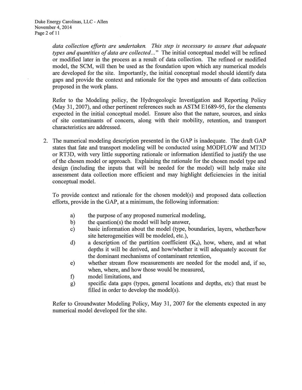
121
122
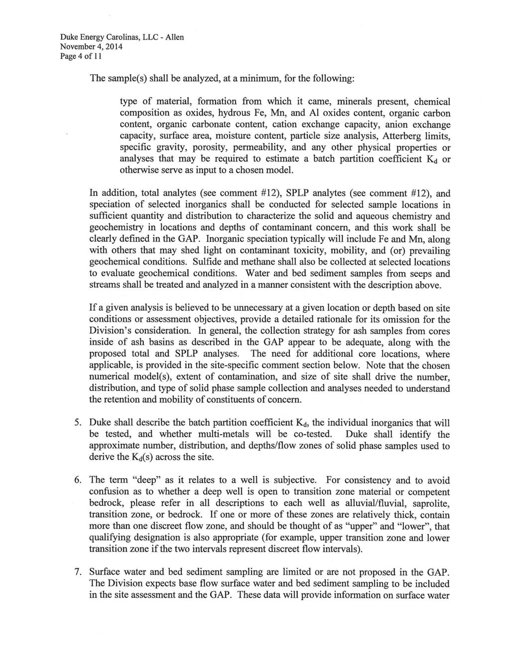
123
124
125
126
127
128
129
D.B. Wilson Station CCR Landfill
 D.B. Wilson Station CCR Landfill Disposal of Coal Combustion Residuals (CCR) from Electric Utilities Final Rule Closure and Post-closure Care Plan October 11, 2016 Prepared By: Project ID: 160030A Big
Hard Hat Services ph: hardhatinc.com 932 N. Wright St., Suite 160 Naperville, IL 60563
 Interstate Power and Light Company Ottumwa Generation Station CCR Surface Impoundment Annual Inspection Report 154.018.015.003 Report issued: July 03, 2017 Hard Hat Services ph: 877-630-7428 hardhatinc.com
Hard Hat Services ph: hardhatinc.com 932 N. Wright St., Suite 160 Naperville, IL 60563
 Interstate Power and Light Company Ottumwa Generation Station CCR Surface Impoundment Annual Inspection Report 154.018.012.003 Report issued: December 21, 2016 Hard Hat Services ph: 877-630-7428 hardhatinc.com
CCR Landfill 2017 Annual Inspection Report NC1 Ash Disposal Area
 CCR Landfill 2017 Annual Inspection Report NC1 Ash Disposal Area Omaha Public Power District Nebraska City Station Nebraska City, Nebraska January 19, 2018 OPPD Nebraska City Station NC1 Ash Disposal Area
TABLE OF CONTENTS 1.0 INTRODUCTION PLAN CERTIFICATION (B)(4) 1
(4) 1") TABLE OF CONTENTS 1.0 INTRODUCTION 1 2.0 PLAN CERTIFICATION 257.102(B)(4) 1 3.0 WRITTEN CLOSURE PLAN 2 3.1 Narrative 2 3.2 CCR Removal 2 3.3 CCR Left in Place 3 3.4 Maximum CCR Inventory 3 3.5 Maximum
TABLE OF CONTENTS 1.0 INTRODUCTION 1 2.0 PLAN CERTIFICATION 257.102(B)(4) 1 3.0 WRITTEN CLOSURE PLAN 2 3.1 Narrative 2 3.2 CCR Removal 2 3.3 CCR Left in Place 3 3.4 Maximum CCR Inventory 3 3.5 Maximum
Closure Plan for CCR Surface Impoundments
 Closure Plan for CCR Surface Impoundments B.L. England Generating Station Beesley s Point, New Jersey April 17, 2018 Prepared For RC Cape May Holdings, LLC 900 North Shore Road Beesley s Point, New Jersey
Coal Combustion Residuals Closure Plan
 Virginia Electric and Power Company Chesterfield Power Station Upper (East) Pond Chesterfield County, Virginia GAI Project Number: C150035.00 October 2016 Prepared by: GAI Consultants, Inc. Richmond Office
Amended Written Closure Plan
 Amended Written Closure Plan Valmont Station - Active CCR Impoundments 3A and 3B Public Service Company of Colorado October 17, 2016 Amended January 5, 2018 Table of Contents 1.0 General Information...
CCR Closure Plan. CCR Certification: Written Closure Plan (b) & (c) for the. Landfill Sedimentation Pond. A. B. Brown Generating Station
 & (c) for the. Landfill Sedimentation Pond. A. B. Brown Generating Station") Submitted to Southern Indiana Gas & Electric Company dba Vectren Power Supply, Inc. (SIGECO) One Vectren Square Evansville, IN 47708 Submitted by AECOM 525 Vine Street, Suite 1800 Cincinnati, Ohio 45202
Submitted to Southern Indiana Gas & Electric Company dba Vectren Power Supply, Inc. (SIGECO) One Vectren Square Evansville, IN 47708 Submitted by AECOM 525 Vine Street, Suite 1800 Cincinnati, Ohio 45202
October 16, GRDA CCR Landfill Compliance Report Grand River Dam Energy Center 8142 Hwy 412B PO Box 609 Chouteau, OK Dear Mr.
 October 16, 2018 Mr. Mike Bednar Superintendent of Environmental Compliance GRDA-Ecosystems and Education Center PO Box 70 420 Hwy 28 Langley, OK 74350-0070 RE: GRDA CCR Landfill Compliance Report Grand
Statistical Method Certification, Coal Combustion Residuals Landfill, Reid Gardner Generating Station
 TECHNICAL MEMORANDUM Statistical Method Certification, Coal Combustion Residuals Landfill, Reid Gardner Generating Station PREPARED FOR: PREPARED BY: REVIEWED BY: NV Energy Nathan Betts, PE/CH2M Charles
TABLE OF CONTENTS LEGAL NOTICE
 Closure Plan for Existing CCR Rev. 0 Surface Impoundments Page No. i TABLE OF CONTENTS 1. INTRODUCTION AND PURPOSE... 1 2. CLOSURE PLAN NARRATIVE DESCRIPTION... 2 3. FINAL COVER SYSTEM DESCRIPTION... 3
Written Closure Plan. Cherokee Station - Active CCR Impoundments Public Service Company of Colorado Denver, Colorado.
 Written Closure Plan Cherokee Station - Active CCR Impoundments Public Service Company of Colorado Denver, Colorado October 17, 2016 Table of Contents 1.0 General Information... 1 2.0 Description of Closure
CCR CLOSURE PLAN Sibley Slag Settling Impoundment Sibley Generating Station East Johnson Rd Sibley, Missouri
 CCR CLOSURE PLAN Sibley Slag Settling Impoundment Sibley Generating Station 33200 East Johnson Rd Sibley, Missouri KCP&L Greater Missouri Operations Company October 14, 2016 TABLE OF CONTENTS SECTION 1
ENGINEER S CERTIFICATION OF AQUIFER SEPARATION DEMONSTRATION (40 CFR )
") PLATTE RIVER POWER AUTHORITY RAWHIDE ENERGY STATION BOTTOM ASH TRANSFER (BAT) IMPOUNDMENTS LARIMER COUNTY, CO ENGINEER S CERTIFICATION OF AQUIFER SEPARATION DEMONSTRATION (40 CFR 257.60) FOR COAL COMBUSTION
PLATTE RIVER POWER AUTHORITY RAWHIDE ENERGY STATION BOTTOM ASH TRANSFER (BAT) IMPOUNDMENTS LARIMER COUNTY, CO ENGINEER S CERTIFICATION OF AQUIFER SEPARATION DEMONSTRATION (40 CFR 257.60) FOR COAL COMBUSTION
TABLE OF CONTENTS LEGAL NOTICE
 Surface Impoundments Page No. i TABLE OF CONTENTS 1. INTRODUCTION... 1 2. PROPOSED CCR IMPOUNDMENT CLOSURE PROCEDURE... 3 3. PROPOSED COVER SYSTEM... 4 4. ESTIMATED MAXIMUM INVENTORY OF CCR... 4 5. ESTIMATED
TABLE OF CONTENTS LEGAL NOTICE
 Closure Plan for Existing CCR Revision: 1 Surface Impoundments Page No. i TABLE OF CONTENTS 1. INTRODUCTION... 1 2. PROPOSED CCR IMPOUNDMENT CLOSURE PROCEDURE... 3 3. PROPOSED COVER SYSTEM... 4 4. ESTIMATED
CCR Fugitive Dust Control Plan
 CCR Fugitive Dust Control Plan Omaha Public Power District North Omaha Station Omaha, Nebraska October 16, 2015 OPPD North Omaha Station CCR Landfill Fugitive Dust Control Plan Table of Contents Revision
CLOSURE PLAN. CFR (b) Bottom Ash Pond Complex Cardinal Plant Brilliant, Ohio. September, 2016
 Bottom Ash Pond Complex Cardinal Plant Brilliant, Ohio. September, 2016") CLOSURE PLAN CFR 257.102(b) Bottom Ash Pond Complex Cardinal Plant Brilliant, Ohio September, 2016 Prepared for: Cardinal Operating Company Cardinal Plant Brilliant, Ohio Prepared by: Geotechnical Engineering
CLOSURE PLAN CFR 257.102(b) Bottom Ash Pond Complex Cardinal Plant Brilliant, Ohio September, 2016 Prepared for: Cardinal Operating Company Cardinal Plant Brilliant, Ohio Prepared by: Geotechnical Engineering
COAL COMBUSTION RESIDUALS (CCR) FUGITIVE DUST CONTROL PLAN SANDY CREEK ENERGY STATION RIESEL, TEXAS. Prepared for:
 FUGITIVE DUST CONTROL PLAN SANDY CREEK ENERGY STATION RIESEL, TEXAS. Prepared for:") COAL COMBUSTION RESIDUALS (CCR) FUGITIVE DUST CONTROL PLAN SANDY CREEK ENERGY STATION RIESEL, TEXAS Prepared for: SANDY CREEK SERVICES, LLC P.O. Box 370 Riesel, Texas 76682 Prepared by: SCS ENGINEERS TBPE
COAL COMBUSTION RESIDUALS (CCR) FUGITIVE DUST CONTROL PLAN SANDY CREEK ENERGY STATION RIESEL, TEXAS Prepared for: SANDY CREEK SERVICES, LLC P.O. Box 370 Riesel, Texas 76682 Prepared by: SCS ENGINEERS TBPE
Mr. Michael Malone CPS Energy 145 Navarro Street, Mail Drop San Antonio, Texas Project No
 October 17, 2016 Mr. Michael Malone CPS Energy 145 Navarro Street, Mail Drop 100406 San Antonio, Texas 78296 Project No. 0352436 Subject: Compilation of Construction History Calaveras Power Station San
Written Closure Plan. Pawnee Station - North CCR Landfill Public Service Company of Colorado Denver Colorado. October 17, 2016
 Written Closure Plan Pawnee Station - North CCR Landfill Public Service Company of Colorado Denver Colorado October 17, 2016 Revised: March 27, 2019 Table of Contents 1.0 General Information... 3 2.0 Description
Explosive gas migration monitoring for a sanitary landfill facility.
 3745-27-12 Explosive gas migration monitoring for a sanitary landfill facility. (A) Applicability and implementation. This rule applies to the following: (1) The owner or operator of a sanitary landfill
2016 Annual Inspection Report
 2016 Annual Inspection Report for Compliance with the Coal Combustion Residuals Rule (40 CFR Part 257) Pawnee Station 14940 Morgan County Road 24 Brush, Colorado 80723 January 18, 2017 Table of Contents
Written Closure Plan. Comanche Station - Active CCR Surface Impoundment Public Service Company of Colorado Denver, Colorado
 Written Closure Plan Comanche Station - Active CCR Surface Impoundment Public Service Company of Colorado Denver, Colorado October 17, 2016 Table of Contents 1.0 General Information... 1 2.0 Description
COAL COMBUSTION RESIDUALS (CCR) FUGITIVE DUST CONTROL PLAN SANDY CREEK ENERGY STATION RIESEL, TEXAS. Prepared for:
 FUGITIVE DUST CONTROL PLAN SANDY CREEK ENERGY STATION RIESEL, TEXAS. Prepared for:") COAL COMBUSTION RESIDUALS (CCR) FUGITIVE DUST CONTROL PLAN SANDY CREEK ENERGY STATION RIESEL, TEXAS Prepared for: SANDY CREEK SERVICES, LLC P.O. Box 370 Riesel, Texas 76682 Prepared by: SCS ENGINEERS TBPE
COAL COMBUSTION RESIDUALS (CCR) FUGITIVE DUST CONTROL PLAN SANDY CREEK ENERGY STATION RIESEL, TEXAS Prepared for: SANDY CREEK SERVICES, LLC P.O. Box 370 Riesel, Texas 76682 Prepared by: SCS ENGINEERS TBPE
FUGITIVE DUST CONTROL PLAN
 FUGITIVE DUST CONTROL PLAN PLEASANTS LANDFILL Willow Island, WV Allegheny Energy Supply Company, LLC A FirstEnergy Company October 19, 2015 CONTENTS Introduction 1 CCR Unit Description 1 CCR Fugitive Dust
Northern Indiana Public Service Company Michigan City Generating Station Primary Settling Pond Number Annual RCRA CCR Unit Inspection Report
 REPORT Northern Indiana Public Service Company Michigan City Generating Station Primary Settling Pond Number 2 2018 Annual RCRA CCR Unit Inspection Report Submitted to: Northern Indiana Public Service
Annual CCR Landfill Inspection OML Existing Landfill OML Expansion Phase 1
 Annual CCR Landfill Inspection OML Existing Landfill OML Expansion Phase 1 Ottumwa-Midland Landfill Prepared for: Ottumwa-Midland Landfill 15300 130 th Street Ottumwa, Iowa 52501 Prepared by: SCS ENGINEERS
FOUR CORNERS POWER PLANT CLOSURE PLAN (b) UPPER RETENTION SUMP FC_ClosPlan_011_
 UPPER RETENTION SUMP FC_ClosPlan_011_") FOUR CORNERS POWER PLANT CLOSURE PLAN 257.102(b) UPPER RETENTION SUMP FC_ClosPlan_011_20161017 Closure Plan Contents 257.102(b)(1) The owner or operator of a CCR unit must prepare a written closure plan
FOUR CORNERS POWER PLANT CLOSURE PLAN 257.102(b) UPPER RETENTION SUMP FC_ClosPlan_011_20161017 Closure Plan Contents 257.102(b)(1) The owner or operator of a CCR unit must prepare a written closure plan
CLOSURE PLAN. CFR (b) GERS Bottom Ash Pond. Northeastern 3&4 Power Station Oologah, Oklahoma. October, 2016
 GERS Bottom Ash Pond. Northeastern 3&4 Power Station Oologah, Oklahoma. October, 2016") CLOSURE PLAN CFR 257.102(b) Bottom Ash Pond Northeastern 3&4 Power Station Oologah, Oklahoma October, 2016 Prepared for: Public Service Company of Oklahoma Oologah, Oklahoma Prepared by: American Electric
CLOSURE PLAN CFR 257.102(b) Bottom Ash Pond Northeastern 3&4 Power Station Oologah, Oklahoma October, 2016 Prepared for: Public Service Company of Oklahoma Oologah, Oklahoma Prepared by: American Electric
CLOSURE PLAN. CCR (b) GERS East and West Bottom Ash Ponds. Pirkey Power Plant Hallsville, Texas. October, 2016
 GERS East and West Bottom Ash Ponds. Pirkey Power Plant Hallsville, Texas. October, 2016") CLOSURE PLAN CCR 257.102(b) East and West Bottom Ash Ponds Pirkey Power Plant Hallsville, Texas October, 2016 Prepared for : Southwest Electric Power Company - Pirkey Plant Hallsville, Texas Prepared by:
CLOSURE PLAN CCR 257.102(b) East and West Bottom Ash Ponds Pirkey Power Plant Hallsville, Texas October, 2016 Prepared for : Southwest Electric Power Company - Pirkey Plant Hallsville, Texas Prepared by:
HISTORY OF CONSTRUCTION
 HISTORY OF CONSTRUCTION CFR 257.73(c)(1) West Boiler Slag Pond Clifty Creek Plant Madison, Indiana October, 2016 Prepared for: Indiana Kentucky Electric Corporation Prepared by: American Electric Power
CCR Landfill 2015 Annual Inspection Report NC1 Ash Disposal Area
 CCR Landfill 21 Annual Inspection Report NC1 Ash Disposal Area Omaha Public Power District Nebraska City Station Nebraska City, Nebraska January 19, 216 OPPD Nebraska City Station NC1 Ash Disposal Area
Notice of Intent to Close Inactive CCR Surface Impoundments
 Notice of Intent to Close Inactive CCR Surface Impoundments Virginia Electric and Power Company Possum Point Power Station Coal Combustion Residual Surface Impoundments A, B, C, D, and E Dumfries, Virginia
CCR Landfill 2018 Annual Inspection Report North Omaha Ash Landfill
 CCR Landfill 2018 Annual Inspection Report North Omaha Ash Landfill Omaha Public Power District Nebraska City, Nebraska January 18, 2019 OPPD North Omaha Ash Landfill CCR Landfill 2018 Annual Inspection
2018 Annual Inspection Report
 2018 Annual Inspection Report for Compliance with the Coal Combustion Residuals Rule (40 CFR Part 257) Comanche Station 2005 Lime Road Pueblo, Colorado 81006 January 18, 2019 Table of Contents Certification...
CCR Certification: Fugitive Dust Control Plan (b) for the. West Ash Pond. at the. F. B. Culley Generating Station.
 for the. West Ash Pond. at the. F. B. Culley Generating Station.") Submitted to Southern Indiana Gas & Electric Company dba Vectren Power Supply, Inc. (SIGECO) One Vectren Square Evansville, IN 47708 Submitted by AECOM 9400 Amberglen Boulevard Austin, Texas 78729 CCR
Submitted to Southern Indiana Gas & Electric Company dba Vectren Power Supply, Inc. (SIGECO) One Vectren Square Evansville, IN 47708 Submitted by AECOM 9400 Amberglen Boulevard Austin, Texas 78729 CCR
Annual CCR Landfill Inspection. Lansing Landfill. Interstate Power and Light Company. Prepared for:
 Annual CCR Landfill Inspection Lansing Landfill Prepared for: Interstate Power and Light Company Lansing Generating Station 2320 Power Plant Drive Lansing, Iowa 52151 Prepared by: SCS ENGINEERS 2830 Dairy
Initial Annual CCR Landfill Inspection OML Existing Landfill OML Expansion Phase 1
 Initial Annual CCR Landfill Inspection OML Existing Landfill OML Expansion Phase 1 Ottumwa-Midland Landfill Prepared for: Ottumwa-Midland Landfill 15300 130 th Street Ottumwa, Iowa 52501 Prepared by: SCS
Written Closure Plan. Pawnee Station - Active CCR Landfill Public Service Company of Colorado Denver Colorado. October 17, 2016
 Written Closure Plan Pawnee Station - Active CCR Landfill Public Service Company of Colorado Denver Colorado October 17, 2016 Table of Contents 1.0 General Information... 1 2.0 Description of Closure Plan
Whitewater Valley Station Surface Impoundment Coal Combustion Residual Annual Report
 Whitewater Valley Station Wayne County, Indiana GAI Project Number: C151119.07 July 2017 Prepared by: GAI Consultants, Inc. Murrysville Office 4200 Triangle Lane Export, Pennsylvania 15632-1358 Prepared
FUGITIVE DUST CONTROL PLAN
 FUGITIVE DUST CONTROL PLAN PLEASANTS McELROY S RUN DISPOSAL IMPOUNDMENT Willow Island, WV Allegheny Energy Supply Company, LLC A FirstEnergy Company October 19, 2015 CONTENTS Introduction 1 CCR Unit Description
FOUR CORNERS POWER PLANT CLOSURE PLAN (b) COMBINED WASTE TREATMENT POND (CWTP) FC_ClosPlan_012_
 COMBINED WASTE TREATMENT POND (CWTP) FC_ClosPlan_012_") FOUR CORNERS POWER PLANT CLOSURE PLAN 257.102(b) COMBINED WASTE TREATMENT POND (CWTP) FC_ClosPlan_012_20161017 Closure Plan Contents 257.102(b)(1) The owner or operator of a CCR unit must prepare a written
FOUR CORNERS POWER PLANT CLOSURE PLAN 257.102(b) COMBINED WASTE TREATMENT POND (CWTP) FC_ClosPlan_012_20161017 Closure Plan Contents 257.102(b)(1) The owner or operator of a CCR unit must prepare a written
CLOSURE PLAN. CCR (b) GERS Landfill Area. Welsh Power Plant Pittsburg, Texas. October, 2016
 GERS Landfill Area. Welsh Power Plant Pittsburg, Texas. October, 2016") CLOSURE PLAN CCR 257.102(b) Landfill Area Welsh Power Plant Pittsburg, Texas October, 2016 Prepared for : Southwest Electric Power Company Welsh Plant Pittsburg, Texas Prepared by: American Electric Power
CLOSURE PLAN CCR 257.102(b) Landfill Area Welsh Power Plant Pittsburg, Texas October, 2016 Prepared for : Southwest Electric Power Company Welsh Plant Pittsburg, Texas Prepared by: American Electric Power
CLOSURE PLAN. CFR (b) Document ID: GERS Bottom Ash Complex. Mountaineer Plant New Haven, West Virginia.
 Document ID: GERS Bottom Ash Complex. Mountaineer Plant New Haven, West Virginia.") CLOSURE PLAN CFR 257.102(b) Bottom Ash Complex Mountaineer Plant New Haven, West Virginia October, 2016 Prepared for : Appalachian Power Company - Mountaineer Plant New Haven, West Virginia Prepared by:
CLOSURE PLAN CFR 257.102(b) Bottom Ash Complex Mountaineer Plant New Haven, West Virginia October, 2016 Prepared for : Appalachian Power Company - Mountaineer Plant New Haven, West Virginia Prepared by:
Annual Inspection Report of CCR Impoundment and CCR Landfill Wenck Project # B
 Technical Memo To: Brian Trower, From: Peter Daniels, PE (Iowa PE# 21569) Dave Parenteau, PE (MN), Wenck Associates, Inc. Date: Subject: Annual Inspection Report of CCR Impoundment and CCR Landfill Wenck
CHOLLA POWER PLANT CLOSURE PLAN (b) SEDIMENTATION POND CH_ClosPlan_004_
 SEDIMENTATION POND CH_ClosPlan_004_") CHOLLA POWER PLANT CLOSURE PLAN 257.102(b) SEDIMENTATION POND CH_ClosPlan_004_20161017 Closure Plan Contents 257.102(b)(1) The owner or operator of a CCR unit must prepare a written closure plan that describes
CHOLLA POWER PLANT CLOSURE PLAN 257.102(b) SEDIMENTATION POND CH_ClosPlan_004_20161017 Closure Plan Contents 257.102(b)(1) The owner or operator of a CCR unit must prepare a written closure plan that describes
CCR Closure Plan Ash Impoundment
 CCR Closure Plan Ash Impoundment Iatan Generating Station Kansas City Power & Light Company Project No. 87292 Revision 0 4/13/2018 CCR Closure Plan Ash Impoundment prepared for Kansas City Power & Light
COAL COMBUSTION RESIDUAL (CCR) FUGITIVE DUST CONTROL PLAN
 FUGITIVE DUST CONTROL PLAN") COAL COMBUSTION RESIDUAL (CCR) FUGITIVE DUST CONTROL PLAN Plant Gaston October 2015 Professional Engineer Certification: Based upon my knowledge, information, and belief that the content in the attached
COAL COMBUSTION RESIDUAL (CCR) FUGITIVE DUST CONTROL PLAN Plant Gaston October 2015 Professional Engineer Certification: Based upon my knowledge, information, and belief that the content in the attached
COAL COMBUSTION RESIDUALS FUGITIVE DUST CONTROL PLAN
 ~ Colorado Springs Utilities Ir's h
STRUCTURAL STABILITY ASSESSMENT
 STRUCTURAL STABILITY ASSESSMENT CFR 257.73(d) Fly Ash Reservoir II Cardinal Plant Brilliant, Ohio October, 2016 Prepared for: Cardinal Operating Company Cardinal Plant Brilliant, Ohio Prepared by: Geotechnical
APPENDIX J HYDROLOGY AND WATER QUALITY
 APPENDIX J HYDROLOGY AND WATER QUALITY J-1 Technical Report on Airport Drainage, Northern Sector Airport and Ordinance Creek Watershed / Preliminary Creek Constructed Natural Channel Culvert J-2 Preliminary
Pre-Application Document Kaweah Project (FERC Project No. 298)
") TABLE OF CONTENTS Page 3.12 Aesthetic Resources... 3.12-1 3.12.1 Information Sources... 3.12-1 3.12.2 Setting... 3.12-1 3.12.3 Project Facilities... 3.12-2 3.12.4 Previous Visual Resources Assessment...
TABLE OF CONTENTS Page 3.12 Aesthetic Resources... 3.12-1 3.12.1 Information Sources... 3.12-1 3.12.2 Setting... 3.12-1 3.12.3 Project Facilities... 3.12-2 3.12.4 Previous Visual Resources Assessment...
CCR Unit Closure and Post-Closure Plan. The business of sustainability. Texas Municipal Power Agency Gibbons Creek Steam Electric Station
 CCR Unit Closure and Post-Closure Plan Texas Municipal Power Agency Gibbons Creek Steam Electric Station Grimes County, Texas October 12, 2016 www.erm.com The business of sustainability Texas Municipal
Northern Indiana Public Service Company (NIPSCO) 2723 East 1500 North, Wheatfield, Indiana, USA Golder Associates Inc.
 2723 East 1500 North, Wheatfield, Indiana, USA Golder Associates Inc.") Northern Indiana Public Service Company R.M. Schahfer Generating Station Fourth Annual RCRA CCR Unit Inspection Report Restricted Waste Type I Landfill - Operating Permit Number 37-01 Submitted to: Northern
Northern Indiana Public Service Company R.M. Schahfer Generating Station Fourth Annual RCRA CCR Unit Inspection Report Restricted Waste Type I Landfill - Operating Permit Number 37-01 Submitted to: Northern
COAL COMBUSTION RESIDUAL (CCR) FUGITIVE DUST CONTROL PLAN
 FUGITIVE DUST CONTROL PLAN") COAL COMBUSTION RESIDUAL (CCR) FUGITIVE DUST CONTROL PLAN Plant Barry October 2015 Professional Engineer Certification: Based upon my knowledge, information, and belief that the content in the attached
COAL COMBUSTION RESIDUAL (CCR) FUGITIVE DUST CONTROL PLAN Plant Barry October 2015 Professional Engineer Certification: Based upon my knowledge, information, and belief that the content in the attached
RULES OF THE OIL AND GAS PROGRAM DIVISION OF WATER RESOURCES CHAPTER DRILLING WELLS TABLE OF CONTENTS
 RULES OF THE OIL AND GAS PROGRAM DIVISION OF WATER RESOURCES CHAPTER 0400-52-06 DRILLING WELLS TABLE OF CONTENTS 0400-52-06-.01 Drilling Equipment 0400-52-06-.03 Casingheads 0400-52-06-.02 Blowout Prevention
ANNUAL INSPECTION BY A QUALIFIED PROFESSIONAL ENGINEER ALL CCR IMPOUNDMENTS CCR Rule Section (b)
") ANNUAL INSPECTION BY A QUALIFIED PROFESSIONAL ENGINEER ALL CCR IMPOUNDMENTS ASBURY POWER PLANT 21133 Uphill Lane Asbury, Missouri 64832 January 18, 2019 LIBERTY UTILITIES Empire District Prepared by: Rachel
ANNUAL INSPECTION BY A QUALIFIED PROFESSIONAL ENGINEER ALL CCR IMPOUNDMENTS ASBURY POWER PLANT 21133 Uphill Lane Asbury, Missouri 64832 January 18, 2019 LIBERTY UTILITIES Empire District Prepared by: Rachel
First Annual RCRA CCR Unit Inspection Report January 2016 RESTRICTED WASTE TYPE I LANDFILL OPERATING PERMIT NUMBER 37-01
 NORTHERN INDIANA PUBLIC SERVICE COMPANY R.M. SCHAHFER GENERATING STATION First Annual RCRA CCR Unit Inspection Report January 2016 REPORT RESTRICTED WASTE TYPE I LANDFILL OPERATING PERMIT NUMBER 37-01
NC DIVISION OF WATER RESOURCES (NCDWR) THIRD ROUND OF DAN RIVER FISH TISSUE METALS FOLLOWING
 THIRD ROUND OF DAN RIVER FISH TISSUE METALS FOLLOWING") NC DIVISION OF WATER RESOURCES (NCDWR) THIRD ROUND OF DAN RIVER FISH TISSUE METALS FOLLOWING THE EDEN COAL ASH SPILL (10 MONTH POST-SPILL ASSESSMENT), MAY 18, 2015. Key Findings Results for the NCDWR s
NC DIVISION OF WATER RESOURCES (NCDWR) THIRD ROUND OF DAN RIVER FISH TISSUE METALS FOLLOWING THE EDEN COAL ASH SPILL (10 MONTH POST-SPILL ASSESSMENT), MAY 18, 2015. Key Findings Results for the NCDWR s
If you have any questions or comments, please feel free to contact me at
 Phone: 256.847.0780 Fax: 256.8470905 matrixdesigngroup.com October 3, 2013 Mr. Eric Sanderson Chief, Solid Waste Branch, Land Division Alabama Department of Environmental Management P.O. Box 301463 Montgomery,
2018 INSPECTION REPORT
 2018 INSPECTION REPORT NORTHERN INDIANA PUBLIC SERVICE COMPANY R.M. SCHAHFER GENERATING STATION Third Annual RCRA CCR Unit Inspection Report January 2018 RESTRICTED WASTE TYPE I LANDFILL OPERATING PERMIT
LEGAL NOTICE. Report No. SL Revision: 0 Page No. i. Ottumwa Generating Station Notification of Intent to Initiate Closure
 Page No. i LEGAL NOTICE This report ( Deliverable ) was prepared by Sargent & Lundy, L.L.C. ("S&L"), expressly for the sole use of Alliant Energy ("Alliant") in accordance with the agreement between S&L
USING A LABYRINTH WEIR TO INCREASE HYDRAULIC CAPACITY. Dustin Mortensen, P.E. 1 Jake Eckersley, P.E. 1
 USING A LABYRINTH WEIR TO INCREASE HYDRAULIC CAPACITY Dustin Mortensen, P.E. 1 Jake Eckersley, P.E. 1 Plum Creek Floodwater Retarding Structure No. 6 is located in an area of Kyle, Texas, that is currently
2017 Annual Inspection Report
 2017 Annual Inspection Report for Compliance with the Coal Combustion Residuals Rule (40 CFR Part 257) Comanche Station 2005 Lime Road Pueblo, Colorado 81006 January 18, 2018 Table of Contents Certification...
Big Rivers Electric Corporation - D.B. Wilson Generating Station. Fugitive Dust Control Plan for Coal Combustion Residuals
 Big Rivers Electric Corporation - D.B. Wilson Generating Station Fugitive Dust Control Plan for Coal Combustion Residuals Prepared For: Big Rivers Electric Corporation 201 3rd Street Henderson, KY 42419
La Crescent Township Zoning Ordinance
 La Crescent Township Zoning Ordinance Table of Contents SECTION 1 ~ PREAMBLE, TITLE, SHORT TITLE AND PURPOSE... 1 0101 Preamble... 1 0102 Title... 1 0103 Short Title... 1 0104 Purpose... 1 SECTION 2 ~
Construction Dewatering
 Construction Dewatering Introduction The control of groundwater is one of the most common and complicated problems encountered on a construction site. Construction dewatering can become a costly issue
NIANGUA SNAPSHOT ISSUE Nutrients 2 Suspended Sediment 3 Salinity 4 Summary 5
 Niangua River Watershed Snapshot Volume 14 Number 2 The 125-mile long Niangua River meanders northward from the town of Marshfield on I-44 to the Lake of the Ozarks. Its watershed covers more than 658,000
Ohio EPA. Division of Air Pollution Control. Engineering Guide #78. (also known as DSIWM Guidance Document #1001 and #1002)
") Ohio EPA Division of Air Pollution Control Engineering Guide #78 (also known as DSIWM Guidance Document #1001 and #1002) Question: The Standards of Performance for New Stationary Sources (NSPS) for municipal
Ohio EPA Division of Air Pollution Control Engineering Guide #78 (also known as DSIWM Guidance Document #1001 and #1002) Question: The Standards of Performance for New Stationary Sources (NSPS) for municipal
Coal Combustion Residuals Annual Fugitive Dust Control Report. Prepared for Montana-Dakota Utilities Company R.M. Heskett Station.
 Coal Combustion Residuals 2016 Annual Fugitive Dust Control Report Prepared for Montana-Dakota Utilities Company R.M. Heskett Station December 2016 Coal Combustion Residuals Fugitive Dust Emission Control
3.0 Basin and Watershed Characteristics
 3.0 Basin and Watershed Characteristics 3.1 Basin Characteristics 3.1.1 Crystal Lake Crystal Lake, located in the cities of Burnsville and Lakeville (Dakota County), covers an area of approximately 292
Suitable Applications Check dams may be appropriate in the following situations: To promote sedimentation behind the dam.
 Categories EC Erosion Control SE Sediment Control TC Tracking Control WE Wind Erosion Control Non-Stormwater NS Management Control Waste Management and WM Materials Pollution Control Legend: Primary Category
BROWNFIELD ASSESSMENT, REDEVELOPMENT & REMEDIATION
 BROWNFIELD ASSESSMENT, REDEVELOPMENT & REMEDIATION 1 HOW ENVIRONMENTAL SITE ASSESSMENTS (PHASE I) AFFECT THE PURCHASE OR TRANSFER OF ANY PROPERTY 1 Standard 1 Sunshine State Standards: SS.A.1.4.4, SS.C.1.4
Pathways of a conservative contaminant: Infiltration, fracture conduits, and re-emergence of chloride in wells and streams
 Pathways of a conservative contaminant: Infiltration, fracture conduits, and re-emergence of chloride in wells and streams Mark Holden M.S., C.G. Environmental Specialist III John Hopeck, Ph.D. Environmental
Maine Department of Environmental Protection (MEDEP) Stone Farm, Arundel Sample Collection - Data Report Summary Report Date: June 15, 2017
 Stone Farm, Arundel Sample Collection - Data Report Summary Report Date: June 15, 2017") Maine Department of Environmental Protection (MEDEP) Stone Farm, Arundel Sample Collection - Data Report Summary Report Date: June 15, 2017 --------------------------------------------------------------------------------------------------------------------------
Maine Department of Environmental Protection (MEDEP) Stone Farm, Arundel Sample Collection - Data Report Summary Report Date: June 15, 2017 --------------------------------------------------------------------------------------------------------------------------
2016 Annual Inspection Report
 2016 Annual Inspection Report for Compliance with the Coal Combustion Residuals Rule (40 CFR Part 257) Comanche Station 2005 Lime Road Pueblo, Colorado 81006 January 18, 2017 Table of Contents Certification...
Holding Pond Annual Inspection Report
 Holding Pond Annual Inspection Report Shiras Steam Plant Project Number: 445171 January 12, 218 Holding Pond Annual Inspection Report Prepared for: Shiras Steam Plant Marquette, Michigan Prepared by: Brian
APPENDIX C VEGETATED EMERGENCY SPILLWAY. VERSION 1.0 March 1, 2011
 APPENDIX C VEGETATED EMERGENCY SPILLWAY VERSION 1.0 March 1, 2011 [NOTE: Could use a better photo more clearly showing the emergency spillway in the context of the dam.] SECTION C-1: DESCRIPTION OF PRACTICE
Big Rivers Electric Corporation - Sebree Generating Station (R. A. Reid, R. D. Green and HMPL Station Two)
") Big Rivers Electric Corporation - Sebree Generating Station (R. A. Reid, R. D. Green and HMPL Station Two) Fugitive Dust Control Plan for Coal Combustion Residuals Prepared For: Big Rivers Electric Corporation
Big Rivers Electric Corporation - Sebree Generating Station (R. A. Reid, R. D. Green and HMPL Station Two) Fugitive Dust Control Plan for Coal Combustion Residuals Prepared For: Big Rivers Electric Corporation
SOUTH CAROLINA ELECTRIC & GAS COMPANY COLUMBIA, SOUTH CAROLINA
 SOUTH CAROLINA ELECTRIC & GAS COMPANY COLUMBIA, SOUTH CAROLINA SALUDA HYDROELECTRIC PROJECT FERC PROJECT NO. 516 DESCRIPTION OF SALUDA HYRDOELECTRIC PROJECT EXHIBIT A AUGUST 2008 Prepared by: SOUTH CAROLINA
Final Report August 2005
 2.0 REGIONAL STUDY AREA 2.1 Regional Setting 2.1.1 Topography The Los Angeles Region is located within the western portion of the Transverse Ranges Geomorphic Province. The San Andreas transform fault
Mecklenburg County. Fish Consumption Advisories A Local Government Perspective
 Mecklenburg County Fish Consumption Advisories A Local Government Perspective David Caldwell Charlotte-Mecklenburg Storm Water Services Water Quality Program NCLMS October 4, 2012 Lake monitoring program
Holding Pond Annual Inspection Report
 Holding Pond Annual Inspection Report Shiras Steam Plant Project Number: 6445171 January 12, 217 Holding Pond Annual Inspection Report Prepared for: Shiras Steam Plant Marquette, Michigan Prepared by:
ANNUAL INSPECTION BY A QUALIFIED PROFESSIONAL ENGINEER ALL CCR IMPOUNDMENTS CCR Rule Section (b)
") ANNUAL INSPECTION BY A QUALIFIED PROFESSIONAL ENGINEER ALL CCR IMPOUNDMENTS ASBURY POWER PLANT 21133 Uphill Lane Asbury, Missouri 64832 January 18, 2017 EMPIRE DISTRICT ELECTRIC COMPANY Prepared by: Rachel
ANNUAL INSPECTION BY A QUALIFIED PROFESSIONAL ENGINEER ALL CCR IMPOUNDMENTS ASBURY POWER PLANT 21133 Uphill Lane Asbury, Missouri 64832 January 18, 2017 EMPIRE DISTRICT ELECTRIC COMPANY Prepared by: Rachel
22. Specialty Valves.
 22. Specialty Valves. a. Types of Specialty Valves. 1) Use of the following specialty valves is covered in this section: Altitude Valve, Pressure Reducing Valve, Pressure Relief Valve, Swing Check Valve,
EPA R6 Dive Team Operations Report. San Jacinto Waste Pits Channelview, TX December 9-10, 2015
 EPA R6 Dive Team Operations Report San Jacinto Waste Pits Channelview, TX December 9-10, 2015 BACKGROUND The San Jacinto River Waste Pit Site history has been documented in several documents prepared for,
Green CCR Surface Impoundment
 Green CCR Surface Impoundment Disposal of Coal Combustion Residuals (CCR) from Electric Utilities Final Rule CCR Impoundment 2017 Annual Inspection Report January 11, 2018 Prepared By: Project ID: 170138A
Annex E Bridge Pier Protection Plan
 Annex E Bridge Pier Protection Plan Table E1 Bridge Types and Locations Table E2 Flow Conditions For River Sections Figure E1 Bridge Abutment Protection Figure E2 Bridge Pier Protection Figure E3 Central
ITEM 400 STRUCTURAL EXCAVATION AND BACKFILL
 AFTER MARCH 1, 2012 ITEM 400 STRUCTURAL EXCAVATION AND BACKFILL 400.1 Description. This item shall govern for all excavation required for the construction of all structures, except pipe or box sewers for
Mecklenburg County Health Ordinance Rules Governing Residential Swimming Pools
 Mecklenburg County Health Ordinance Rules Governing Residential Swimming Pools Mecklenburg County Health Department 700 N. Tryon Street, Suite 211 Charlotte, North Carolina 28202-2236 Phone (704) 336-5103
Oakmont Area Structure Plan
 Oakmont Area Structure Plan Bylaw 12/97 Consolidated by Bylaw 25/2013 (Approved August 26, 2013) CITY OF ST. ALBERT CONSOLIDATION OF BYLAW 12/97 Consolidated by Bylaw 25/2013 Being a bylaw to adopt the
SITE S7: EMBANKMENT FAILURE WEST OF MILLARVILLE
 LANDSLIDE RISK ASSESSMENT SOUTHERN REGION SITE S7: EMBANKMENT FAILURE WEST OF MILLARVILLE LEGAL LOCATION: LSD 4-3-21-4 W5M and 1-4-21-4 W5M REFERENCE LOCATION ALONG HIGHWAY The slide area is located between
Pore-Air Entrapment during Infiltration
 Pore-Air Entrapment during Infiltration GEO-SLOPE International Ltd. www.geo-slope.com 1200, 700-6th Ave SW, Calgary, AB, Canada T2P 0T8 Main: +1 403 269 2002 Fax: +1 888 463 2239 Introduction Infiltration
Juneau Douglas Harbor
 Juneau Douglas Harbor Douglas Harbor Page 2 of 8 Condition of Improvements 31 December 2015 Douglas Harbor, Alaska (CWIS No. 072789, 180942) Authorization Rivers and Harbors Act, 3 July 1958 (House Doc.
Bathing Water Profile - Carne (2017)
") Bathing Water Profile - Carne (2017) Bathing Water: Bathing Water Code: Local Authority: River Basin District: Monitoring Point: Carne IESEBWC050_0000_0300 Wexford County Council South Eastern 312952E,
Bathing Water Profile - Carne (2017) Bathing Water: Bathing Water Code: Local Authority: River Basin District: Monitoring Point: Carne IESEBWC050_0000_0300 Wexford County Council South Eastern 312952E,
2016 Annual Landfill Inspection Report. SCE&G Wateree Station Class III Landfill
 2016 Annual Landfill Inspection Report for the SCE&G Wateree Station Class III Landfill in Eastover, SC County of Richland January 15, 2017 Annual Inspection Report The Annual Inspection Report is performed
Remedial Investigation Report And Sediment Quality Evaluation. Pre-1941 Sewage Treatment Plant Site
 FINAL Remedial Investigation Report And Sediment Quality Evaluation Pre-1941 Sewage Treatment Plant Site U. S. Army Installation Fort Monmouth Fort Monmouth, New Jersey Directorate of Public Works February
INADVERTENT RETURN PLAN FOR HORIZONTAL DIRECTIONAL DRILLING (HDD)
") INADVERTENT RETURN PLAN FOR HORIZONTAL DIRECTIONAL DRILLING (HDD) FACILITY OPERATOR: NextEra Energy Resources, LLC 700 Universe Boulevard Juno Beach, FL 33408 For Horizontal Directional Drilling Contents
INADVERTENT RETURN PLAN FOR HORIZONTAL DIRECTIONAL DRILLING (HDD) FACILITY OPERATOR: NextEra Energy Resources, LLC 700 Universe Boulevard Juno Beach, FL 33408 For Horizontal Directional Drilling Contents