WELCOME to CAUx Local India 2018
|
|
|
- Elfreda Morgan
- 5 years ago
- Views:
Transcription

1 WELCOME to CAUx Local India 2018


2 Flange Design In Detail Prepared by Sachin Pol and Fauzan Badiwale


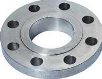
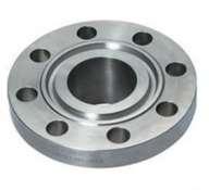
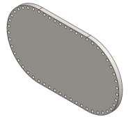

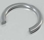
3 Some Typical Flange Images 3


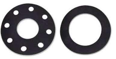
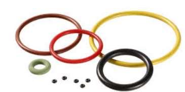
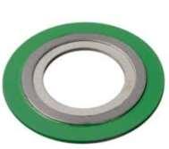
4 Some Typical Gasket Images 4
5 Flange Design As Per ASME Sec.VIII Div.1 Mandatory Apendix.2 - Scope:- The rules apply specifically to the design of bolted flange connections with gaskets that are entirely within the circle enclosed by the bolt holes and with no contact outside this circle, and are to be used in conjunction with the applicable requirements in Subsections A, B, and C of this Division. Non Circular Flanges can be done as per 2-10 for circular bores only. 5


6 6
7 Flange Design As Per ASME Sec.VIII Div.1 Mandatory Apendix.2 - Scope:- The rules apply specifically to the design of bolted flange connections with gaskets that are entirely within the circle enclosed by the bolt holes and with no contact outside this circle, and are to be used in conjunction with the applicable requirements in Subsections A, B, and C of this Division. Non Circular Flanges can be done as per 2-10 for circular bores only We can Use standards listed in UG-44 like B16.5, B16.47 One can use other types of flanged connections provided they are designed in accordance with good engineering practice and method of design is acceptable to the Inspector. Flanged covers as shown in Figure 1-6; Bolted flanges using full face gaskets flanges using means other than bolting to restrain the flange 7 assembly against pressure

8 8 Full Face Gasketed Flanges
9 Some Important Considerations as per Appendix.2 Flanges made from ferritic steel shall be full annealed, normalized, normalized and tempered, or quenched and tempered when the thickness of the flange section exceeds 3 in. (75 mm). It is recommended that bolts and studs have a nominal diameter of not less than 1/2 in. (13 mm) 9
10 Types Of Flanges (1) Loose Type Flanges. This type covers those designs in which the flange has no direct connection to the nozzle neck, vessel, or pipe wall, and designs where the method of attachment is not considered to give the mechanical strength equivalent of integral attachment. See Figure 2-4 sketches (1), (1a), (2), (2a), (3), (3a), (4), (4a), (4b), and (4c) for typical loose type flanges and the location of the loads and moments 10
11 (1) Loose Type Flanges. There is no bevel or cut given in flange for welding. 11
12 Types Of Flanges (2) Integral Type Flanges. This type covers designs where the flange is cast or forged integrally with the nozzle neck, vessel or pipe wall, butt welded there to or attached by other forms of arc or gas welding of such a nature that the flange and nozzle neck, vessel or pipe wall is considered to be the equivalent of an integral structure. See Figure 2-4 sketches (5), (6), (6a), (6b), and (7) for typical integral type flanges 12
13 (2) Integral Type Flanges. Full welding is done though out the thk of flange. There is Full penetration butt weld provided between flange and shell or nozzle. 13
14 Types Of Flanges (3) Optional Type Flanges. This type covers designs where the attachment of the flange to the nozzle neck, vessel, or pipe wall is such that the assembly is considered to act as a unit, which shall be calculated as an integral flange. For simplicity the designer may calculate the construction as a loose type flange provided none of the following values is exceeded Figure 2-4 sketches (8), (8a), (9), (9a), (10),(10a), and (11) for typical optional type flanges. 14
15 (3) Optional Type Of Flanges. There is bevel or cut given in flange for welding. 15
16 Flange Design... Design Conditions (1) Operating Conditions. The conditions required to resist the hydrostatic end force of the design pressure tending to part the joint and to maintain on the gasket or joint contact surface sufficient compression to assure a tight joint, all at the design temperature. The minimum load is a function of the design pressure, the gasket material and the effective gasket or contact area to be kept tight under pressure, per eq. (c)(1)(1) sufficient compression to assure a tight joint all at the design temperature. 16
17 Flange Design... Design Conditions (2) Gasket Seating Condition. The conditions existing when the gasket or joint contact surface is seated by applying an initial load with the bolts when assembling the joint, at atmospheric temperature and pressure. The minimum initial load considered to be adequate for proper seatingis a function of the gasket material, and the effective gasket or contact area to be seated, per eq. (c)(2)(2) 17
18 Flange Design... STEP 1: - Calculation of required bolt loads Calculation of required Bolt load for operating condition = Wm1 H = total hydrostatic end force. Hp = total joint contact surface compression load G = diameter at location of gasket load reaction. G is defined as follows (see Table 2-5.2): (a) when bo 1/4 in. (6 mm), G = mean diameter of gasket contact face (b) when bo > 1/4 in. (6 mm), G = outside diameter of gasket contact face less 2b b = effective gasket or joint contact surface seating width 18
19 19
20 Flange Design... STEP 1: - Calculation of required bolt loads Calculation of required Bolt load for Gasket Seating Condition = Wm2 y = Gasket seating Stress. G = diameter at location of gasket load reaction. G is defined as follows (see Table 2-5.2): (a) when bo 1/4 in. (6 mm), G = mean diameter of gasket contact face (b) when bo > 1/4 in. (6 mm), G = outside diameter of gasket contact face less 2b b = effective gasket or joint contact surface seating width 20
21 Flange Design... STEP 2: - Calculation of required bolt Areas Calculation of required Required and Actual Bolt Area (Am and Ab) Total Required cross sectional area of bolt Am = A m = max (Am 1, Am 2 ) Required bolt area for operating condition Am1 = Am 1 = Wm 1 /Sb Required bolt area for Gasket seating condition Am2 = Am 2 = Wm 2 /Sa. Where, Wm1 = Required Bolt load for operating condition Wm2 = Required Bolt load for Gasket seating condition Sa = allowable bolt stress at atmospheric temperature(see UG-23) Sb = allowable bolt stress at design temperature (seeug-23) 21
22 Flange Design... STEP 3: - Maximum Bolt Spacing Between Bolts For vessels in lethal service or when specified by the user or his designated agent, the maximum bolt spacing shall not exceed the value calculated in accordance with eq. (3). Where, a = Bolt diameter t = Flange thickness m = Gasket factor 22
 For operating conditions, For Gasket Seating conditions, By taking avg area instead of only required area Am,we are increasing W and hence the")
23 Flange Design... STEP 4: - Calculation of Flange Design Bolt Load( W) For operating conditions, For Gasket Seating conditions, By taking avg area instead of only required area Am,we are increasing W and hence the thickness to take care of over tightening of flange bolts. For critical applications where lethal service is present full bolt load is considered i.e W = Sa x Ab, And hence designing flange for full strength of bolts. 23
24 Flange Design... STEP 5: - Calculation of Flange Moment( Mo) For operating conditions, Mo = M D + M T + M G Where, M D = component of moment due to H D, = H D. h D H D = hydrostatic end force on area inside of flange = (π/4)xb 2 P h D = radial distance from the bolt circle, to the circle on which H D acts, as prescribed in Table
25 Flange Design... 25
26 Flange Design... STEP 5: - Calculation of Flange Moment( Mo) For operating conditions, Mo = M D + M T + M G Where, M T = component of moment due to H T, = H T. h T H T = difference between total hydrostatic end force and the hydrostatic end force on area inside of flange, acting between gasket diameter G and ID of flange B. = H H D h T = radial distance from the bolt circle to the circle on which H T acts as prescribed in Table
27 Flange Design... 27
28 Flange Design... STEP 5: - Calculation of Flange Moment( Mo) For operating conditions, Mo = M D + M T + M G Where, M G = component of moment due to H G, = H G. h G H G = gasket load (difference between flange design bolt load and total hydrostatic end force) = W H For operating condition h G = radial distance from gasket load reaction to the bolt circle = (C G)/2 28
29 Flange Design... 29
30 Flange Design... STEP 5: - Calculation of Flange Moment( Mo) For Gasket Seating conditions, For Gasket Seating condition 30
31 Flange Design... STEP 6: - Calculation of Bolt Space correction Factor When the bolt spacing exceeds 2a + t, Multiply M O by the bolt spacing correction factor B SC If Bolt spacing exceeds 2a+t 31
 Longitudinal hub stress")
32 Flange Design... STEP 7: - Calculation of Flange Stresses For Integral Type Flanges 1 ) Longitudinal hub stress - S H S T S R 2 ) Radial Flange stress - S R S H 3 ) Tangential Flange stress - S T 32

33 Flange Design... STEP 7: - Calculation of Flange Stresses For Integral Type Flanges PvElite Report 1.5 x S f S T S R S f S H 33


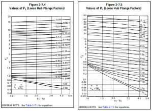
34 Flange Design...Various Factors For Flange Stresses 34
35 Flange Design... STEP 7: - Calculation of Flange Stresses Allowable Stresses For Flange 1 ) Longitudinal hub stress - S H 2 ) Radial Flange stress - S R For Cast iron, S all = S f Where, Sf = Allowable flange stress at design or ambient temperature as applicable. Other than cast iron material For optional type of flanges designed as integral [Figure 2-4 sketches (8), (8a), (9), (9a), (10), (10a), and (11)], also integral type sketch(7)] S all = Smaller (1.5S f, 1.5S n ) For integral type flanges with hub welded to the neck, pipe or vessel wall sketches (6), (6a), and (6b) 35 S all = Smaller (1.5S f, 2.5S n ) S all = S f 3 ) Tangential Flange stress - S T S all = S f 4 ) Combined stresses S H + S R 2, S H + S T <= S f 2 <= S f
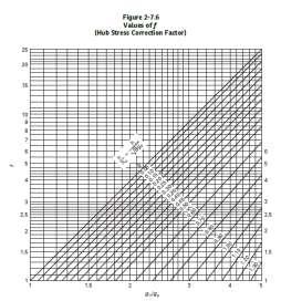
36 Flange Design... STEP 7: - Calculation of Flange Stresses For Loose Ring Type Flanges 1 ) Longitudinal hub stress - S H 2 ) Radial Flange stress - S R Where, M o = total moment acting upon the flange, for the operating conditions or gasket seating as may apply t = flange thickness B = inside diameter of flange g1 = thickness of hub at back of flange f,l,e,y,z = Factors. f = hub stress correction factor for integral flangesfrom Figure ) Tangential Flange stress - S T 36
37 Flange Rigidity Flanges that have been designed based on allowable stress limits alone may not be sufficiently rigid to control leakage. The rigidity factors provided in Table 2-14 have been proven through extensive user experience for a wide variety of joint design and service conditions. The use of the rigidity index does not guarantee a leakage rate within established limits but it should be considered as one of factors for joint design. Successful service experience may be used as an alternative to the flange rigidity rules for fluid services that are nonlethal and non-flammable without exceeding following conditions. The temperature range of 20 F ( 29 C) to 366 F (186 C) Design pressures of 150 psi (1 035 kpa). 37
38 Flange Rigidity E = modulus of elasticity for the flange material at design temperature (operating condition) or at atmospheric temperature (gasket seating condition), psi J = rigidity index 1 KI = rigidity factor for integral or optional flange types = 0.3 KL = rigidity factor for loose type flanges =
39 How to define Flange Geometry For Integral Type Flanges Select Flange I.D = Shell I.D Assume Flange thickness Take g o as equal to shell thickness Assume g1 such a way that 1:3 taper requirement satisfies, give hub length as at least as (g1- go)*3 Select Size of bolt From TEMA table D-5M give the minimum Hub to bolt dimension and hence finalize P.C.D of bolt. From TEMA table D-5M give the minimum Bolt to Edge dimension and hence finalize O.D of Flange Define this as gasket O.D Consider gasket width and decide gasket I.D Specify gasket m and Y factors Check bolt area requirement and give no of bolts If bolt area is sufficient then check minimum and maximum bolt spacing requirements. If required fine tune the dimensions. Don t use bolt below M16 size. Check required thickness and give thickness more than this. Check and provide if needed counter flange bolt loads. Check for moments and axial loads and apply them if applicable. Always keep rigidity index check box on. 39 If corrosion is there check on the corrosion check box as well.
40 Defining Flange Geometry- Integral Flange Select Flange Type 40
41 Defining Flange Geometry- Integral Flange Define Flange I.D Put Flange I.D = Shell I.D 41
42 Defining Flange Geometry- Integral Flange Assume Flange Thickness 42
43 Defining Flange Geometry- Integral Flange Define g0 Put g0 = Shell nominal thk provided 43
44 Defining Flange Geometry- Integral Flange Define g1 and hub length Put g1 = g0 + 8 to 10 mm, here taken as 9mm Hub length= (g1- g0)*3 = (17-8)*3 = 27 44
45 Defining Flange Geometry- Integral Flange Define bolt type,size and numbers Select Bolt type Give Size of bolt Give no. Of Bolts 45

46 Defining Flange Geometry- Integral Flange Define Bolt PCD and Flange O.D 46
47 Defining Flange Geometry- Integral Flange Define Bolt PCD and Flange O.D Flange O.D = * = ~1146 PCD = * * = ~
48 Defining Flange Geometry- Integral Flange Define Gasket parameters M and y factors for gasket Face I.D = Flange I.D I.D = * 15 = 1044 Face O.D = Gasket O.D Gasket width Gasket O.D = = 1074 Clearance between bolt inner Bolt hole for M20 bolt size edge and gasket O.D 48
49 Defining Flange Geometry- Integral Flange Checking Bolt Area Increase no of bolts to satisfy bolt area Bolt Area is insufficient 49
50 Defining Flange Geometry- Integral Flange Checking Bolt Area No of bolts increased to satisfy bolt area 50
51 Defining Flange Geometry- Integral Flange Fine tune dimensions Required thickness is insufficient, Increase it 51

52 Defining Flange Geometry- Integral Flange Fine tune dimensions Thickness increased Now Flange Thickness is passed 52

53 Defining Flange Geometry- Integral Flange Plot of Flange 53

54 Defining Flange Geometry- Integral Flange If gasket is defined from flange I.D Gasket O.D = I.D +2*15=1030 When Gasket I.D = Flange I.D Required Thickness is increased considerably 54

55 Defining Gasket Width As Per ASME Section VIII Div.1 As Per TEMA 55
56 Defining Gasket Width As Per ASME Section VIII Div.2 56


57 Transferring Bolt loads, forces and moments on flange When Bolt Loads are different on Flanges? When Flanges on both sides of tubesheet are having different pressure, temperature or gaskets. In case of TEMA AES type of construction shell side bonnet flanges are having different diameters. 57
58 Transferring Bolt loads, forces and moments on flange How to apply Forces and Moments on Flanges? When there are external forces and moments present on the flange joint its effect will be considered according to Kellogg s Equation 4.F P e = π.g M π.g 3 This P e is simply added to the design pressure P Where, F is external axial force on flange. According to Div 2 equation this axial force will have to be considered if it is tensile i.e. pulling force, in other case the value to be taken as zero. 58
59 Thank You! Have a great conversation!
Tutorial on Flange Qualification using CAEPIPE
 Tutorial on Flange Qualification using CAEPIPE This document explains the procedure on performing Flange Qualification using CAEPIPE. General Flange joints are essential components in all pressurized systems;
OPENINGS AND REINFORCEMENTS 26
 ASME BPVC.VIII.1-2015 UG-35.2 UG-36 (4) It is recognized that it is impractical to write requirements to cover the multiplicity of devices used for quick access, or to prevent negligent operation or the
Design and Optimization of Weld Neck Flange for Pressure Vessel
 V th International Symposium on Fusion of Science & Technology, New Delhi, India, January 18-22, 2016 ID: 2016-ISFT-430 Design and Optimization of Weld Neck Flange for Pressure Vessel Vinod Kumar 1, Vivek
THE PROCESS OF JOINT INTEGRITY
 BOLTED JOINTS A.333 THE PROCESS OF JOINT INTEGRITY To assist in managing a process, ask yourself the following questions: why, what, who, and how? Why do we need a Flange Joint Integrity program? This
AWWA Pipe Flanges. AWWA C Standard Steel Hub Flanges Class D AWWA C Standard Steel Hub Flanges Class E AWWA C Flange Manufacturer
 WW Pipe Flanges WW Flanges are commonly used in waterworks, wastewater, slurry, plant piping or other light duty applications generally requiring pressures of less than 300 psi. Pressure ratings for WW
CERTIFICATION OF COMPLIANCE OF THE USER S DESIGN SPECIFICATION
 CERTIFICATION OF COMPLIANCE OF THE USER S DESIGN SPECIFICATION I, the undersigned, being experienced and competent in the applicable field of design related to pressure vessel requirements relative to
Liquefied gas cargo tanks and process pressure vessels
 .1 -.3 Liquefied gas cargo tanks and process pressure vessels.1 General.1.1 The present texts give the general principles which are applied by Classification Societies for approval and survey of the relevant
CONTENTS Article NC-1000 Introduction Figures Article NC-2000 Material
 CONTENTS Foreword... xv Statements of Policy... xvii Personnel... xix Organization of Section III... xxxi Summary of Changes... xxxiii List of Changes in BC Order... xxxiv Article NC-1000 Introduction...
Subject: FRP Flange Design Ref: Thomas E. Graham, FRP Flanges for Process Pipe and Tanks, NACE, 1989
 Britt Engineering Associates, Inc. Birmingham. Alabama www.beacom.com September 30, 2018 Technical Note Subject: FRP Flange Design Ref: Thomas E. Graham, FRP Flanges for Process Pipe and Tanks, NACE, 1989
Rules for the Installation, Inspection and Testing of Air Reservoirs (Other than on Locomotives)
") Rules for the Installation, Inspection and Testing of Air Reservoirs (Other than on Locomotives) December 5, 1994 TM Rules for the Installation, Inspection and Testing of Air Reservoirs (Other than on
Rules for the Installation, Inspection and Testing of Air Reservoirs (Other than on Locomotives) December 5, 1994 TM Rules for the Installation, Inspection and Testing of Air Reservoirs (Other than on
Use equation for the cylindrical section and equation or for the ends.
 Solution 13.1 See section 13.3.4, equations 13.7 to 13.18 Solution 13.2 Use equation 13.34. (a) rigid constant C = 0.43 (b) free to rotate, C = 0.56 Solution 13.3 See section 13.5.1 Use equation 13.39
ASME Boiler & Pressure Vessel Code Analysis of the 1497 MHz High-Current Cryomodule Helium Vessel
 1.0 Introduction ASME Boiler & Pressure Vessel Code Analysis of the 1497 MHz High-Current Cryomodule Helium Vessel Katherine Wilson 28 May 2007 To minimize the hazards associated with vacuum and pressure
MSC Guidelines for Pressure Vessels
 References: a. 46 CFR Part 54 Pressure Vessels S. T. Brady, CDR, Chief, Engineering Division b. ASME Boiler and Pressure Vessel Code (BPVC), Section VIII, Division 1, (1998 Edition) c. Navigation and Inspection
PVP2006-ICPVT
 Proceedings of PVP2006 / ICPVT-11: 11 th International Conference on Pressure Vessel Technology July 23-37, 2006, Vancouver, Canada PVP2006-ICPVT11-93020 DESIGN OF A LARGE RECTANGULAR FLANGE Bharat Batra,
3-PIECE BALL VALVE, 3600 PSI/ PN 248, WITH ISO DIRECT MOUNTING PAD 306M SERIES/ PED Category II
 3-PIECE BALL VALVE, 3600 PSI/ PN 248, WITH ISO DIRECT MOUNTING PAD 306M SERIES/ PED Category II 306M User Manual English Version Use for company in Europe who will place the product on the market, please
Design of Pressure vessel for the Hydrocarbon release from the Vent Header Lines
 Design of Pressure vessel for the Hydrocarbon release from the Vent Header Lines Bhargav Mangesh Joshi 1 1Student, Department of mechanical engineering, Modern college of engineering, Pune-5 ---------------------------------------------------------------------***---------------------------------------------------------------------
MSC Guidelines for Independent Fuel Tanks
 References: Contact Information a. 46 CFR 58.50 (Independent Fuel Tanks) b. 46 CFR 119.440 (Independent Fuel Tanks) c. 46 CFR 182.440 (Independent Fuel Tanks) C. J. Robuck, LCDR, Chief, Engineering Division
Telefon (+45) Telefax (+45)
 Telefax (+45)") Uni-Valve A /S VENTILER & INSTRUMENTER Telefon (+45) 43 43 82 00 Telefax (+45) 43 43 74 75 mail@uni-valve.com www.uni-valve.com UNI-S83 / S84 3/4-way ball valve Installation and Operating manual 3/4-WAY
Uni-Valve A /S VENTILER & INSTRUMENTER Telefon (+45) 43 43 82 00 Telefax (+45) 43 43 74 75 mail@uni-valve.com www.uni-valve.com UNI-S83 / S84 3/4-way ball valve Installation and Operating manual 3/4-WAY
API HPHT 6BX Flange Design, Verification & Capabilities: Example use of Methodology
 API HPHT 6BX Flange Design, Verification & Capabilities: Example use of Methodology January 22 nd, 2018 Summary 1. Determine the suitability of the existing BX gaskets for 20K 2. Use Robert Eichenberg
A parametric study of metal-to-metal contact flanges with optimised. geometry for safe stress and no-leak conditions
 A parametric study of metal-to-metal contact flanges with optimised geometry for safe stress and no-leak conditions M. Abid *, D. H. Nash a * Faculty of Mechanical Engineering, Ghulam Ishaq Khan Institute
Flange Insulation. Gasket Basics. Why Gaskets Are Used:
 Flange Insulation Gasket Basics Why Gaskets Are Used: Gaskets are used to create a static seal between two stationary members of a mechanical assembly and to maintain that seal under operating conditions
2.1 Introduction to pressure vessels
 2.1 Introduction to pressure vessels Pressure vessels in the form of cylinders and tanks are used for storing variety of liquids and gasses at different temperatures and pressures. Some of the substances
Casing Collapse Pressure for Non-zero Internal Pressure Condition. (Effect of Internal Pressure on Collapse)
") Casing Collapse Pressure for Non-zero Internal Pressure Condition (Effect of Internal Pressure on Collapse) Jiang Wu Chevron ETC August, 2011 API specifies casing collapse rating primarily based on casing
Casing Collapse Pressure for Non-zero Internal Pressure Condition (Effect of Internal Pressure on Collapse) Jiang Wu Chevron ETC August, 2011 API specifies casing collapse rating primarily based on casing
Standard Pneumatic Test Procedure Requirements for Piping Systems
 the pressure equipment safety authority Standard Pneumatic Test Procedure Requirements for Piping Systems AB-522 Edition 2, Rev. 1 Issued 2016-10-24 Table of Contents FOREWORD... 1 1.0 INTRODUCTION...
DESIGN AND ANALYSIS OF PRESSURE VESSEL
 DESIGN AND ANALYSIS OF PRESSURE VESSEL Vrushali Dilip Solapurkar 1 Assistant Professor, Mechanical Engineering Department, Vadodara Institute of Engineering, Gujarat, India ABSTRACT This technical paper
INTRODUCTION TABLE OF CONTENTS
 2 INTRODUCTION Thank you for choosing Servometer to design and manufacture your unique, new electrodeposited bellows for your particular application. The definitions, formulas and design parameters inside
Si C132. Safety valves for pressure relief in accordance to PED, DIN/EN and ASME. Engineering GREAT Solutions
 Safety valves for pressure relief in accordance to PED, DIN/EN and ASME Engineering GREAT Solutions Si C132 Features The universal compact safety valve > 3 body seat sizes for appropriate size selection
Quality Plastic Pipe Fittings. Technical Data. Fabricated PVC Fittings IPS Class 100, 125, 160, 200 SCH 40 & SCH 80 Solvent Weld & Gasketed
 Quality Plastic Pipe Fittings Technical Data Fabricated PVC Fittings IPS Class 100, 125, 160, 200 SCH 40 & SCH 80 Solvent Weld & Gasketed Effective April 1, 2002 PIPE DIMENSIONS IPS-IRON PIPE SIZE Minimum
ASYBCO 90 O ELBOW LONG RADIUS O.D. I.D.
 90 O ELBOW LONG RADIUS Standard weight Extra strong Schedule 160 Double extra strong ASTM A-234 ASME / ANSI B16.9 Carbon and ferritic alloy steel Produced from X-rayed, stress-relieve welded pipe. Welds
Tightening Evaluation of New 400A Size Metal Gasket
 Proceedings of the 8th International Conference on Innovation & Management 307 Tightening Evaluation of New 400A Size Metal Gasket Moch. Agus Choiron 1, Shigeyuki Haruyama 2, Ken Kaminishi 3 1 Doctoral
STANDARD SPECIFICATION FOR SPLIT TEES (HOT TAP MATERIAL)
") STANDARD SPECIFICATION FOR SPLIT TEES (HOT TAP MATERIAL) TEE (HOT TAPPING MATERIAL) S-04-02-040 Page 1 of 7 1.0 SCOPE This specification covers the basic requirements for the design, manufacture and supply
STANDARD SPECIFICATION FOR SPLIT TEES (HOT TAP MATERIAL) TEE (HOT TAPPING MATERIAL) S-04-02-040 Page 1 of 7 1.0 SCOPE This specification covers the basic requirements for the design, manufacture and supply
Section GATE VALVES
 Section 02521 PART 1 GENERAL 1.01 SUMMARY This Section includes the furnishing and installation of gate valves for isolation and dead-end service as shown on Plans and as specified herein. 1.02 MEASUREMENT
PC3_ and PC4_ Pipeline Connectors
 1283050/4 IM-P128-06 ST Issue 4 PC3_ and PC4_ Pipeline Connectors Installation and Maintenance Instructions 1. Safety information 2. Description PC30 shown 3. Installation 4. Welding of pipeline connector
Engineered Valves Group. Revision 2. FABRI-VALVE High Performance Knife Gate Valve.
 Engineered Valves Group XS 150 Revision 2 FABRI-VALVE High Performance Knife Gate Valve www.engvalves.com Fabri-Valve XS150 High Performance Knife Gate Valve XS150 High Performance Knife Gate Valve T he
Dean Pump Self-Priming Chemical Process Pumps
 Bulletin C 1.2.34.7 Dean Pump Self-Priming Chemical Process Pumps php Series HEAD CAPACITY RANGE CHARTS php Self Primer - 2 Pole 3500 RPM 500 CAPACITY M 3 /HR 2900 RPM 50 HERTZ 25 50 75 125 150 400 TOTAL
Spilt body Flange ball valve. TC-205MFF-PN1640 User Manual English Version. Document No: TC-205MFF-PN1640.Ur-manual. Date: 2007/04/2617. Version: 1.
 Spilt body Flange ball valve TC-205MFF-PN1640 Series PED Category I,II TC-205MFF-PN1640 User Manual English Version Use for company in Europe who will place the product on the market, please amend which
WHEATLEY Series 500 Swing Check Valve
 Document Number: TC003001-13 Revision: 02 WHEATLEY Series 500 Swing Check Valve Installation, Operation, and Maintenance Manual TABLE OF CONTENTS BILL OF MATERIALS...3 SCOPE...5 INSTALLATION AND OPERATION
IAPMO GUIDE CRITERIA FOR BALL VALVES IAPMO IGC PURPOSE
 INTERNATIONAL ASSOCIATION OF PLUMBING AND MECHANICAL OFFICIALS IAPMO GUIDE CRITERIA FOR BALL VALVES IAPMO IGC 157-20067 1 PURPOSE 1.1 The purpose of this standard is to establish an acceptable standard
Valve Inspection & Testing
 Inspection & Testing in accordance with API 598 Valve Inspection & Testing Shell Test (Body Hydro Test): - Each valve shall be tested in accordance with ASME B 16.34 for ASME valves. Shell test pressure
BALL VALVE ASSEMBLY AND MAINTENANCE PROCEDURE. REF. DOC.MMM900N Rev.1 March 2014 SERIES M DIN / ANSI. Page 1 of 17
 SERIES M DIN / ANSI Page 1 of 17 REVIEW CONTROL PROCEDURE REF.DOC.MMM900N REV. DATE CARRIED OUT BY APPROVED BY DESCRIPTION 0 12/05/2013 E.Hidalgo J.Tejedor Initial Edition 1 27/03/2014 D.Grau J.Tejedor
MSC Guidelines for Refrigeration Machinery
 Procedure Number E1-32 Revision Date: 07/27/10 S. J. Kelly, CDR, Chief of Engineering Division References: a. 46 CFR Part 56.50-105 Low Temperature Piping b. 46 CFR Part 58.20 Refrigeration Machinery c.
The Powerful Sealing Calculation
 KLINGER expert 6.0 The Powerful Sealing Calculation The KLINGER expert 6.0 gasket design program is a versatile software to assist users in the selection of non-metallic gasket materials. www.klinger.co.at
Analysis and Optimization of Stress on Horizontal Pressure Vessel by Varying Opening Angle and Location
 Analysis and Optimization of Stress on Horizontal Pressure Vessel by Varying Opening Angle and Location Bhupendra V. Barjod #1, Prof. Ronak Shah *2 # PG student Mechanical Department, Kalol Institute of
Section 7 AMERICAN. Specials
 Section 7 AMERICAN Specials AMERICAN Specials The principal standards relating to AMERICAN Specials are ANSI/AWWA C110/A21.10, C151/A21.51, and C153/A21.53. These and other standards are referenced throughout
FITTING IDENTIFICATION AMERICANT THREAD TYPES APPENDIX ALFAGOMMA // APPENDIX. Dash numers. NPTF (National Pipe Tapered Fuel)
") // FITTINGS GUIDelines FITTING IDENTIFICATION numers Most fluid piping system sizes are measured by dash numbers. These are universally used abbreviations for the size of component expressed as the numerator
// FITTINGS GUIDelines FITTING IDENTIFICATION numers Most fluid piping system sizes are measured by dash numbers. These are universally used abbreviations for the size of component expressed as the numerator
Table NC (e)-1 Stress Range Reduction Factors
-1 Stress Range Reduction Factors") RECORD 15-997 8/2017 PAGE 1 OF 13 (3) If the range of temperature change varies, equivalent full temperature cycles may be computed as follows: Table NC-3611.2(e)-1 Stress Range Reduction Factors Number
RECORD 15-997 8/2017 PAGE 1 OF 13 (3) If the range of temperature change varies, equivalent full temperature cycles may be computed as follows: Table NC-3611.2(e)-1 Stress Range Reduction Factors Number
P-04 Stainless Steel Corrugated Hoses and Metal Bellows Expansion Joints
 Guideline No.P-04 (201510) P-04 Stainless Steel Corrugated Hoses and Metal Bellows Expansion Joints Issued date: 20 th October 2015 China Classification Society Foreword This Guideline is a part of CCS
PIP PNE00012 Piping Examination and Leak Test Guide
 October 2017 Piping PIP PNE00012 Piping Examination and Leak Test Guide PURPOSE AND USE OF PROCESS INDUSTRY PRACTICES In an effort to minimize the cost of process industry facilities, this Practice has
Optimize Nozzle Location For Minimization Of Strees In Pressure Vessel
 IJIRST International Journal for Innovative Research in Science & Technology Vol. 1, Issue 1, June 2014 ISSN(online): 2349-6010 Optimize Nozzle Location For Minimization Of Strees In Pressure Vessel Shyam
Dual position solenoid valve Type ICSH 25-80
 Data sheet Dual position solenoid valve Type ICSH 25-80 ICSH dual position solenoid valve belongs to the ICV family and consists of an ICV housing, an ICS insert together with an ICSH top cover with 2
WHEATLEY WHEATLEY SERIES 500 SWING CHECK VALVE. Installation, Operation and Maintenance Manual
 WHEATLEY SERIES 500 SWING CHECK VALVE STANDARD INTEGRAL SEAT & OPTIONAL REMOVABLE SEAT 2" FP - 6" FP 150# - 1500# 8" FP - 12" FP 150# - 900# API 6D and B16.34 2" FP - 4" FP 5000# DRILLING PRODUCTION VALVE
DUPLEX TECHNICAL INFORMATION FABRICATED DUPLEX STRAINERS
 DUPLEX STRAINER TECHNICAL INFORMATION - 119 - SCREEN OPENINGS 100 Mesh - 30% O.A. 0.006 Openings 80 Mesh - 36% O.A. 0.008 Openings 60 Mesh - 38% O.A. 0.010 Openings 40 Mesh - 41% O.A. 0.016 Openings 30
API-510 PRESSURE VESSEL INSPECTOR
 BODY OF KNOWLEDGE API-510 PRESSURE VESSEL INSPECTOR CERTIFICATION EXAMINATION July 2013 (Replaces July 2012) API Authorized Pressure Vessel Inspectors must have a broad knowledge base relating to maintenance,
Design and Analysis of Pressure Safety Release Valve by using Finite Element Analysis
 Design and Analysis of Pressure Safety Release Valve by using Finite Element Analysis Mr.V.D.Rathod* 1, Prof.G.A.Kadam* 2, Mr.V. G. Patil* 3 * 1 M.E. Design (Pursuing), SKN Sinhgad Institute of Technology&
Annex G (normative) Requirements for Nondestructive Examination
 Requirements for Nondestructive Examination") Purchase API Spec online at http://www.techstreet.com/api Annex G (normative) G.1 General Requirements for Nondestructive Examination This annex specifies the requirements for NDE that shall be performed
Purchase API Spec online at http://www.techstreet.com/api Annex G (normative) G.1 General Requirements for Nondestructive Examination This annex specifies the requirements for NDE that shall be performed
Horizontal Bladder Tanks
 DATA SHEET Horizontal Bladder Tanks Features UL Listed and FM Approved for use with various ANSUL proportioners and foam concentrates 175 psi (12.1 bar) maximum allowable working pressure (design pressure)
PVP Copyright 2009 by ASME
 Proceedings of PVP 009 009 ASME Pressure Vessel and Piping Division Conference July 6-30, 009, Prague, Czech Republic PVP009-7746 UPDATE OF THE TABULATED «M AND Y» VALUES IN THE NEW REVISIONS OF FRENCH
Hatch cover securing and tightness
 (1986) (Rev 1 1996) (Corr.1 June 2000) (Rev.2 July 2005) (Corr.1 Oct 2005) Hatch cover securing and tightness 1. Application 1.1 The following recommendations apply to steel hatch covers that are fitted
Hardened Steel Washers
 USS (Type A Wide) Flat Washers Hardened Steel Washers Grade 8 S.A.E. Dimensions American Standard Lbs. Per No./Pcs. Gauge M Pcs. Per Lb. 3/16 9/16 1/4 18 (3/64) 2.8 361 1/4 3/4 5/16 16 (1/16) 6.7 149 5/16
ROTATING DISK VALVES INSTALLATION AND MAINTENANCE 1. SCOPE 3 2. INFORMATION ON USAGE 3 3. VALVE TYPES 3 4. OPERATORS 5 5. VALVE CONSTRUCTION 6
 Sub Section INDEX Page Number 1. SCOPE 3 2. INFORMATION ON USAGE 3 3. VALVE TYPES 3 4. OPERATORS 5 5. VALVE CONSTRUCTION 6 6. INSTALLATION AND OPERATION 6 7. MAINTENANCE 8 8. REPAIR 9 9. ASSEMBLY 10 10.
INTERLOCKED METAL HOSE
 INTERLOCKED METAL HOSE HOSE FUNDAMENTALS Penflex interlocked metal hoses are made for a variety of specialized industrial applications and are available in a wide range of metals, styles and sizes. Interlocked
Guide for Evaluating Your Hose Assembly Supplier
 Guide for Evaluating Your Hose Assembly Supplier Supplier Evaluation Checklist, and How to Clearly Define Application Requirements Safe, reliable hose assemblies require appropriate specification work
Design and Safety Document for the Vacuum Windows of the NPDGamma Liquid Hydrogen Target at SNS
 Design and Safety Document for the Vacuum Windows of the NPDGamma Liquid Hydrogen Target at SNS Prepared: Checked: Approved: H. Nann W. Fox M. Snow The NPDGamma experiment is going to run at BL13 at SNS
Engineering Data Sheet
 Page 1 of 6 CE MARKING AND THE PRESSURE EQUIPMENT DIRECTIVE 97/23/EC Valves must be installed into a well designed system and it is recommended that the system be inspected in accordance with the appropriate
PROCEDURES FOR REPAIRS TO ASME NV STAMPED PRESSURE RELIEF DEVICES OF NUCLEAR SAFETY RELATED PRESSURE RELIEF VALVES
 NB16 0603 NR Task Group 1 9 16 1. One update by NR task group page 3: 7/17/19 2. Two updates to S6.1 and S6.3 on page 1: 7/19/17 SUPPLEMENT 6 PROCEDURES FOR REPAIRS TO ASME NV STAMPED PRESSURE RELIEF DEVICES
SECTION BUTTERFLY VALVES
 SECTION 15112 BUTTERFLY VALVES PART 1 GENERAL 1.01 SUMMARY A. All butterfly valves shall be of the tight closing, rubber seated type and fully comply with the latest revision of AWWA Standard C504, Class
Installation, Operating and Maintenance Instructions. V914 Cast Iron Flanged Swing Check Valve V914
 Installation, Operating and Maintenance Instructions V914 Cast Iron Flanged Swing Check Valve V914 THE PRESSURE EQUIPMENT DIRECTIVE 97/23/EC and CE MARKING The Pressure Equipment Regulations 1999 (SI 1999/2001)
Model MTB-ASME Vertical Bladder Tanks
 DATA SHEET Model MTB-ASME Vertical Bladder Tanks Features n UL Listed for use with various proportioners and foam concentrates n 175 psi (12.1 bar) maximum allowable working pressure (design pressure)
Installation, Operation and Maintenance Manual for Back Pressure Regulator
 Installation, Operation and Maintenance Manual for Back Pressure Regulator Model 8860 2009 Groth Corporation IOM-8860 Rev. B 12541 Ref. ID: 95565 Page 2 of 13 Table of Contents I. INTRODUCTION 3 II. DESIGN
Other Si min/max. Cr min/max. 0.4/ / / / Bal.
 178.46 Specification 3AL seamless aluminum cylinders. (a) Size and service pressure. A DOT 3AL cylinder is a seamless aluminum cylinder with a imum water capacity of 1000 pounds and minimum service pressure
Model MTB-ASME Horizontal Bladder Tanks
 DATA SHEET Model MTB-ASME Horizontal Bladder Tanks Features n UL Listed and FM Approved for use with various proportioners and foam concentrates n 175 psi (12.1 bar) maximum allowable working pressure
Model PIV UL/FM Post Indicator Valve. Maintenance and Operation Manual UL/FM Post Indicator Valve Configuration AWWA C515
 Model 2010 -PIV UL/FM Post Indicator Valve Maintenance and Operation Manual UL/FM Post Indicator Valve Configuration AWWA C515 2 LAYOUT AND SITING At the design stage, it should be considered where valves
Model MTB-ASME Vertical Bladder Tanks
 DATA SHEET Model MTB-ASME Vertical Bladder Tanks Features n UL Listed for use with various proportioners and foam concentrates n 175 psi (12.1 bar) maximum allowable working pressure (design pressure)
Unit 1, Fullerton Road Rotherham S60 1DJ. Tele: Fax:
 Unit 1, Fullerton Road Rotherham S60 1DJ Tele: 0845 601 333 6 Fax: 0845 601 333 7 info@fabricatedproducts.co.uk www.fabricatedproducts.co.uk Data Sheet 6.0 Rubber Pump Flexes All rubber bellows are suitable
BALL VALVE ASSEMBLY AND MAINTENANCE PROCEDURE FOR LCV BALL VALVES REF. DOC. MMM LCVE Rev.0 July 2010 SERIES SFF & SFR.
 SERIES SFF & SFR SFF / SFR EN/ANSI/ASME/API/BS/NF SFF EN/DIN/BS/NF Page 1 of 16 REVIEW CONTROL PROCEDURE REF.: DOC. MMM LCVE REV. DATE CARRIED OUT BY APPROVED BY DESCRIPTION 0 19/07/2010 J. Rubio J.Tejedor
Vertical Bladder Tanks
 DATA SHEET Vertical Bladder Tanks Features UL Listed and FM Approved for use with various ANSUL proportioners and foam concentrates 175 psi (12.1 bar) maximum allowable working pressure (design pressure)
PRESSURE RETEST. 49 CFR, (g) Co#: Vin#: DOT Spec: MAWP:
 Co#: Vin#: DOT Spec: MAWP:") PRESSURE RETEST 49 CFR, 180.407(g) Co#: Vin#: Spec: MAWP: Retest Date: Location: *External Inspection Performed: *Internal Inspection Performed: Test Pressure: psig Held for: min. (Must be at least 10
PRESSURE RETEST 49 CFR, 180.407(g) Co#: Vin#: Spec: MAWP: Retest Date: Location: *External Inspection Performed: *Internal Inspection Performed: Test Pressure: psig Held for: min. (Must be at least 10
Sprocket Selection Guidelines
 Sprocket Selection Guidelines Table 1 Information Necessary to Order Sprockets 1. Chain Size Number, type, or drawing number of the chain to be used on the sprocket. (The suitability of a sprocket depends
ASSE International Product (Seal) Listing Program. ASSE Performance Requirements for Air Valve and Vent Inflow Preventer
 Listing Program. ASSE Performance Requirements for Air Valve and Vent Inflow Preventer") ASSE International Product (Seal) Listing Program ASSE 1063-2016 Performance Requirements for Air Valve and Vent Inflow Preventer Manufacturer: Contact Person: E-mail: Address: Laboratory: Laboratory File
ASSE International Product (Seal) Listing Program ASSE 1063-2016 Performance Requirements for Air Valve and Vent Inflow Preventer Manufacturer: Contact Person: E-mail: Address: Laboratory: Laboratory File
Rules for piping design, construction and testing
 .1 Rules for piping design, construction and testing.1 Foreword (1981) (Rev.1 1987) (Rev.2 Nov 2001) The present requirements are related to piping-systems made of carbon, carbon-manganese, alloy steels
Flange Bolt Torquing. for Resistoflex Plastic-Lined Piping Products. Torquing. Retorquing. Hydrotesting. Annual retorquing
 Flange Bolt Torquing for Resistoflex Plastic-Lined Piping Products Torquing When assembling flange connections, always use a full complement of clean, new high strength A193-B7 bolting. If using stainless
Installation Instructions
 Installation Instructions Durametallic MD-200 Series Gas Dual Cartridge Canister Seal for Mixers and Agitators Experience In Motion 1 Equipment Check 1.1 Follow plant safety regulations prior to equipment
SpeciÞcations. Engine Dimensions Dimensions in millimeters. Inch equivalents shown in [].
![SpeciÞcations. Engine Dimensions Dimensions in millimeters. Inch equivalents shown in [].](/thumbs/77/75006228.jpg "SpeciÞcations. Engine Dimensions Dimensions in millimeters. Inch equivalents shown in [].") SpeciÞcations Engine Dimensions Dimensions in millimeters. Inch equivalents shown in []. Ê ßÔ Ê ÛÝ Ñ Ê Û ÎÊ Û É 5 ENGINE IDENTIFICATION NUMBERS Kohler engine identiþcation numbers (model, speciþcation
SpeciÞcations Engine Dimensions Dimensions in millimeters. Inch equivalents shown in []. Ê ßÔ Ê ÛÝ Ñ Ê Û ÎÊ Û É 5 ENGINE IDENTIFICATION NUMBERS Kohler engine identiþcation numbers (model, speciþcation
MONOLITHIC ISOLATING JOINTS: The Sealing Systems
 MONOLITHIC ISOLATING JOINTS: The Sealing Systems State of the Art and comparison among the several e systems. s NGPR0501 1 rev.0 dated 15-10-2005 - Copyright 2005 NuovaGiungas srl ITALY. Introduction The
TECHNICAL DATA OBSOLETE
 June 1, 2008 Foam 240a 1. DESCRIPTION The Chemguard Bladder Tank is one component in a balanced pressure foam proportioning system. It requires no external power, other than the water pressure to ensure
SURFACE CASING SELECTION FOR COLLAPSE, BURST AND AXIAL DESIGN FACTOR LOADS EXERCISE
 SURFACE CASING SELECTION FOR COLLAPSE, BURST AND AXIAL DESIGN FACTOR LOADS EXERCISE Instructions Use the example well data from this document or the powerpoint notes handout to complete the following graphs.
Берг АБ Тел. (495) , факс (495) Turning Ideas Into Engineered Solutions KAYDON RING & SEAL, INC.
 , факс (495) Turning Ideas Into Engineered Solutions KAYDON RING & SEAL, INC.") Turning Ideas Into Engineered Solutions RING & SEAL, INC. K-CBS Series Circumferential Barrier Seals Kaydon s high performance circumferential barrier seals back up DGS systems with performance & economy.
Turning Ideas Into Engineered Solutions RING & SEAL, INC. K-CBS Series Circumferential Barrier Seals Kaydon s high performance circumferential barrier seals back up DGS systems with performance & economy.
A Rationale for Pressure Relief Device(s) Qualification Requirements (LH2)
 Qualification Requirements (LH2)") UN-GTR PART A INSERTION Stand 09.02.2011, 17:20 Uhr A.3.3 HYDROGEN STORAGE SYSTEM The hydrogen storage system consists of all components that form the primary pressure boundary of the stored hydrogen in
UN-GTR PART A INSERTION Stand 09.02.2011, 17:20 Uhr A.3.3 HYDROGEN STORAGE SYSTEM The hydrogen storage system consists of all components that form the primary pressure boundary of the stored hydrogen in
Regulating valves REG-SA and REG-SB
 MAKING MODERN LIVING POSSIBLE Technical brochure Regulating valves REG-SA and REG-SB REG-SA and REG-SB are angleway and straightway hand regulating valves, which act as normal stop valves in closed position.
Inflatable Packer Single & Double. Single & Double Packer Dimension. Wireline Packer. Water Testing Packer (WTP) Packer
 Packer") Inflatable Packer Single & Double Single & Double Packer Dimension Wireline Packer Water Testing Packer (WTP) Packer Packer Working Pressure & Depth Chart Packer Water Hand Pump Packer Air Driven Pump
Inflatable Packer Single & Double Single & Double Packer Dimension Wireline Packer Water Testing Packer (WTP) Packer Packer Working Pressure & Depth Chart Packer Water Hand Pump Packer Air Driven Pump
Hand-operated regulating valves in stainless steel Types REG-SA SS and REG-SB SS
 Data sheet Hand-operated regulating valves in stainless steel Types REG-SA SS and REG-SB SS In certain specific areas such as outdoor applications and corrosive atmospheres, such as coastal installations,
A new concept in the storage of liquefied chemical and petrochemical gases Zero leakage Zero fugitive emissions
 A new concept in the storage of liquefied chemical and petrochemical gases Zero leakage Zero fugitive emissions Introduction Industries involved in the handling of dangerous fluids have to answer increasing
Technical data. Back pressure limit: 27.5% of set pressure. Capacity certification: ASME Boiler & Pressure Vessel Code Section I and VIII
 VALVES & CONTROLS CROSBY SAFETY VALVES H ig h C a p a c it y, S t e a m S e r v ic e, F la n g e d S t e e l S a f e t y V a lv e Introduction Crosby Style HSL is a full nozzle reaction type safety valve
TECHNICAL MANUAL. COPRA Anchoring Coupler. For Smart Bolted Connections
 TECHNICAL MANUAL Anchoring Coupler For Smart Bolted Connections Version: PEIKKO GROUP 03/2017 Anchoring Coupler For bolted connections Multi-purpose anchoring system for all bolted connections Simplifi
DR.ING. CARLO AVANZINI PROFESSIONAL ENGINEER GRIP TEST REPORT NOVA SIRIA, ROLETTO, Premise
 GRIP TEST REPORT NOVA SIRIA, ROLETTO, 07.10.2013 1. Premise The present report covers the witnessing of the test conducted in the Nova Siria Factory in Roletto (Torino, Italy) to verify the behavior of
GREIG FILTERS, INC. OPERATION MANUAL
 GREIG FILTERS, INC. OPERATION MANUAL MODEL DCFH 3P 15/3 100 S4 DOE/222 DUAL CARTRIDGE FILTER HOUSING TABLE OF CONTENTS I. INTRODUCTION II. CARTRIDGE FILTER HOUSING UNIT A. OPERATION B. INSTALLATION C.
Vessels subject to External Pressure
 Basic principles of compressive force Vessels subject to External Pressure Before After The result of just air pressure! Presented by: Ray Delaforce Basic principles of compressive force Consider For a
Limited quantities of compressed gases.
 173.306 Limited quantities of compressed gases. (a) Limited quantities of compressed gases for which exceptions are permitted as noted by reference to this section in 172.101 of this subchapter are excepted
Casing Spacer Technology Leaders
 Casing Spacer Technology Leaders Benefit today. Save down the line. www.racispacers.com NORTH AMERICA Why Raci Raci has been the global leader in casing spacer technology since 1952. Our uniquely designed,
E.2 Series. High efficiency circulator. Technical overview
 E.2 Series High efficiency Technical File No:.165 Date: june 05, 2017 Supersedes:.165 Date: october 08, 2015 contents Motor data 4 Technical data 4 Materials of construction 4 Dimensions and weights 5