TEMPORARY TRAFFIC CONTROL ELEMENTS
|
|
|
- Imogen Francis
- 6 years ago
- Views:
Transcription
1 PART 6. TEMPORARY TRAFFIC CONTROL TABLE OF CONTENTS Page CHAPTER 6A. Section 6A.01 CHAPTER 6B. GENERAL General...6A-1 FUNDAMENTAL PRINCIPLES Section 6B.01 Fundamental Principles of Temporary Traffic Control... 6B-1 CHAPTER 6C. TEMPORARY TRAFFIC CONTROL ELEMENTS Section 6C.01 Temporary Traffic Control Plans... 6C-1 Section 6C.02 Temporary Traffic Control Zones... 6C-2 Section 6C.03 Components of Temporary Traffic Control Zones... 6C-3 Section 6C.04 Advance Warning Area... 6C-3 Section 6C.05 Transition Area... 6C-4 Section 6C.06 Activity Area... 6C-4 Section 6C.07 Termination Area... 6C-8 Section 6C.08 Tapers... 6C-8 Section 6C.09 Detours and Diversions... 6C-12 Section 6C.10 One-Lane, Two-Way Traffic Control... 6C-13 Section 6C.11 Flagger Method of One-Lane, Two-Way Traffic Control... 6C-13 Section 6C.12 Deleted Section 6C.13 Pilot Car Method of One-Lane, Two-Way Traffic Control... 6C-15 Section 6C.14 Temporary Traffic Control Signal Method of One-Lane, Two-Way Traffic Control... 6C-15 Section 6C.15 Stop or Yield Control Method of One-Lane, Two-Way Traffic Control...6C-15 CHAPTER 6D. Section 6D.01 Section 6D.02 CHAPTER 6E. PEDESTRIAN AND WORKER SAFETY Pedestrian Considerations...6D-1 Worker Considerations...6D-4 FLAGGER CONTROL Section 6E.01 Qualifications for Flaggers... 6E-1 Section 6E.02 High-Visibility Clothing... 6E-1 Section 6E.03 Hand-Signaling Devices... 6E-2 Section 6E.04 Flagger Procedures... 6E-3 Section 6E.05 Flagger Stations... 6E-5 TC6-1
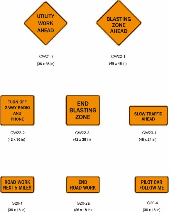
2 CHAPTER 6F. TEMPORARY TRAFFIC CONTROL ZONE DEVICES Section 6F.01 Types of Devices...6F-1 Section 6F.02 General Characteristics of Signs...6F-1 Section 6F.03 Sign Placement...6F-3 Section 6F.04 Sign Maintenance...6F-7 Section 6F.05 Regulatory Sign Authority...6F-7 Section 6F.06 Regulatory Sign Design...6F-7 Section 6F.07 Regulatory Sign Applications...6F-7 Section 6F.08 ROAD (STREET) CLOSED Sign (R11-2)...6F-11 Section 6F.09 Local Traffic Only Signs (R11-3a, R11-4)...6F-11 Section 6F.10 Weight Limit Signs (R12-1, R12-2, R12-5)...6F-12 Section 6F.11 STAY IN LANE Sign (R4-9)...6F-12 Section 6F.12 PEDESTRIAN CROSSWALK Sign (R9-8)... 6F-12 Section 6F.13 SIDEWALK CLOSED Signs (R9-9, R9-10, R9-11, R9-11a)...6F-12 Section 6F.14 Special Regulatory Signs...6F-13 Section 6F.15 Warning Sign Function, Design, and Application...6F-13 Section 6F.16 Position of Advance Warning Signs...6F-21 Section 6F.17 ROAD (STREET) WORK Sign (CW20-1)...6F-22 Section 6F.18 DETOUR Sign (CW20-2)...6F-22 Section 6F.19 ROAD (STREET) CLOSED Sign (CW20-3)...6F-23 Section 6F.20 ONE LANE ROAD Sign (CW20-4)...6F-23 Section 6F.21 LANE(S) CLOSED Signs (CW20-5, CW20-5a)...6F-23 Section 6F.22 CENTER LANE CLOSED AHEAD Signs (CW9-3, CW9-3a)...6F-24 Section 6F.23 THRU TRAFFIC MERGE RIGHT (LEFT) Sign (CW4-1a)...6F-24 Section 6F.24 Deleted Section 6F.25 ON RAMP Plaque (CW13-4)...6F-24 Section 6F.26 RAMP NARROWS Sign (CW5-4)...6F-24 Section 6F.27 SLOW TRAFFIC AHEAD Sign (CW23-1)...6F-25 Section 6F.28 EXIT OPEN, EXIT CLOSED Signs (E5-2, E5-2a)...6F-25 Section 6F.29 Flagger Sign (CW20-7,CW20-7a)...6F-25 Section 6F.30 Two-Way Traffic Sign (CW6-3)...6F-25 Section 6F.31 Workers Sign (CW21-1, CW21-1a)...6F-26 Section 6F.32 FRESH OIL (TAR) Sign (CW21-2)...6F-26 Section 6F.33 ROAD MACHINERY AHEAD Sign (CW21-3)...6F-26 Section 6F.34 SHOULDER WORK Signs (CW21-5, CW21-5a, CW21-5b)...6F-26 Section 6F.35 SURVEY CREW Sign (CW21-6)...6F-27 Section 6F.36 UTILITY WORK Sign (CW21-7)...6F-27 Section 6F.37 Signs for Blasting Areas...6F-27 Section 6F.38 BLASTING ZONE AHEAD Sign (CW22-1)...6F-28 Section 6F.39 TURN OFF 2-WAY RADIO AND PHONE Sign (CW22-2)...6F-28 Section 6F.40 END BLASTING ZONE Sign (CW22-3)...6F-28 Section 6F.41 SHOULDER DROP-OFF Sign (CW8-9a)...6F-28 Section 6F.42 UNEVEN LANES Sign (CW8-11)...6F-29 Section 6F.43 NO CENTER STRIPE Sign (CW8-12)...6F-29 Section 6F.44 Other Warning Signs...6F-29 Section 6F.45 Advisory Speed Plaque (CW13-1)...6F-29 Section 6F.46 Supplementary Distance Plaque (CW7-3a)...6F-30 TC6-2
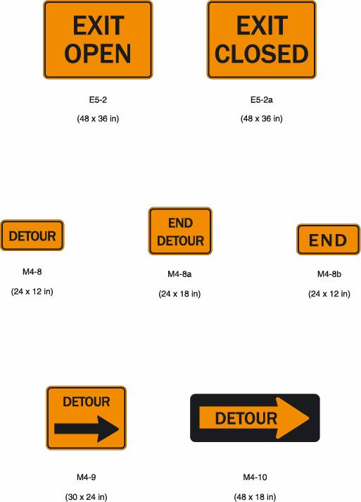
3 Section 6F.47 Section 6F.48 Section 6F.49 Section 6F.50 Section 6F.51 Section 6F.52 Section 6F.53 Section 6F.54 Section 6F.55 Section 6F.56 Section 6F.57 Section 6F.58 Section 6F.59 Section 6F.60 Section 6F.61 Section 6F.62 Section 6F.63 Section 6F.64 Section 6F.65 Section 6F.66 Section 6F.67 Section 6F.68 Section 6F.69 Section 6F.70 Section 6F.71 Section 6F.72 Section 6F.73 Section 6F.74 Section 6F.75 Section 6F.76 Section 6F.77 Section 6F.78 Section 6F.79 Section 6F.80 CHAPTER 6G. Section 6G.01 Section 6G.02 Section 6G.03 Section 6G.04 Section 6G.05 Guide Signs...6F-30 ROAD WORK NEXT XX KM (MILES) Sign (G20-1)...6F-31 END ROAD WORK Sign (G20-2a)...6F-31 Detour Signs and Markers (M4-8, M4-8a, M4-8b, M4-9, and M4-10)...6F-31 PILOT CAR FOLLOW ME Sign (G20-4)...6F-32 Portable Changeable Message Signs...6F-33 Arrow Panels...6F-35 High-Level Warning Devices (Flag Trees)...6F-39 Channelizing Devices...6F-40 Cones...6F-43 Tubular Markers...6F-44 Vertical Panels...6F-45 Drums...6F-45 Type I, II, or III Barricades...6F-46 Direction Indicator Barricades...6F-49 Temporary Traffic Barriers as Channelizing Devices...6F-49 Edgeline Channelizers...6F-50 Opposing Traffic Lane Divider...6F-50 Pavement Markings...6F-50 Temporary Pavement Markings...6F-51 Raised Pavement Markers...6F-52 Delineators...6F-53 Lighting Devices...6F-53 Floodlights...6F-54 Flashing Warning Beacons...6F-54 Warning Lights...6F-55 Steady-Burn Electric Lamps...6F-56 Temporary Traffic Control Signals...6F-56 Temporary Traffic Barriers...6F-58 Crash Cushions...6F-60 Vehicle-Arresting Systems...6F-61 Rumble Strips...6F-61 Screens...6F-62 Future and Experimental Devices...6F-62 TYPE OF TEMPORARY TRAFFIC CONTROL ZONE ACTIVITIES Typical Applications...6G-1 Work Duration...6G-1 Location of Work...6G-5 Modifications To Fulfill Special Needs...6G-5 Work Outside of Shoulder...6G-7 TC6-3
4 Section 6G.06 Section 6G.07 Section 6G.08 Section 6G.09 Section 6G.10 Section 6G.11 Section 6G.12 Section 6G.13 Section 6G.14 Section 6G.15 Section 6G.16 Section 6G.17 Section 6G.18 Section 6G.19 CHAPTER 6H. Section 6H.01 Work on the Shoulder with No Encroachment...6G-8 Work on the Shoulder with Minor Encroachment...6G-9 Work Within the Median...6G-10 Work Within the Traveled Way of Two-Lane Highways...6G-10 Work Within the Traveled Way of Urban Streets...6G-11 Work Within the Traveled Way of Multilane, Nonaccess Controlled Highways...6G-12 Work Within the Traveled Way at an Intersection...6G-14 Work Within the Traveled Way of Expressways and Freeways...6G-16 Two-Lane, Two-Way Traffic on One Roadway of a Normally Divided Highway...6G-17 Crossovers...6G-17 Interchanges...6G-18 Movable Barriers...6G-18 Work in the Vicinity of Highway-Rail Grade Crossings...6G-18 Control of Traffic Through Incident Areas...6G-19 TYPICAL APPLICATIONS Typical Applications...6H-1 FIGURES CHAPTER 6C. TEMPORARY TRAFFIC CONTROL ELEMENTS Figure 6C-1 Component Parts of a Temporary Traffic Control Zone... 6C-5 Figure 6C-2 Types of Tapers and Buffer Spaces... 6C-9 Figure 6C-3 Example of a One-Lane, Two-Way Traffic Taper... 6C-14 CHAPTER 6E. FLAGGER CONTROL Figure 6E-1 Use of Hand-Signaling Devices by Flaggers... 6E-4 CHAPTER 6F. Figure 6F-1 Figure 6F-2 Figure 6F-3 Figure 6F-4 TEMPORARY TRAFFIC CONTROL ZONE DEVICES Height and Lateral Location of Signs - Typical Installations...6F-4 Methods of Mounting Signs Other Than on Posts...6F-6 Advance Warning Arrow Display Specifications...6F-37 Channelizing Devices...6F-41 TC6-4
5 CHAPTER 6H. TYPICAL APPLICATIONS Figure 6H-1 Work Beyond the Shoulder (TA-1)...6H-7 Figure 6H-2 Work on Very Low Volume Rural Road (TA-2)...6H-9 Figure 6H-3 Work on Shoulders (TA-3)...6H-11 Figure 6H-4 Short Duration or Mobile Operation on Shoulder (TA-4)...6H-13 Figure 6H-5 Shoulder Closure on Freeway (TA-5)...6H-15 Figure 6H-6 Shoulder Work with Minor Encroachment (TA-6)...6H-17 Figure 6H-7 Road Closure with Diversion (TA-7)...6H-19 Figure 6H-8 Road Closure with Off-Site Detour (TA-8)...6H-21 Figure 6H-9 Overlapping Routes with Detour (TA-9)...6H-23 Figure 6H-10 Lane Closure for One Lane Two Way Traffic Control (TA-10)...6H-25 Figure 6H-11 Lane Closure on Low-Volume Two-Lane Road (TA-11)...6H-27 Figure 6H-12 Lane Closure on Two-Lane Road Using Traffic Control Signals (TA-12)...6H-29 Figure 6H-13 Temporary Road Closure (TA-13)...6H-31 Figure 6H-14 Haul Road Crossing (TA-14)...6H-33 Figure 6H-15 Work in Center of Low-Volume Road (TA-15)...6H-35 Figure 6H-16 Surveying Along Centerline of Low-Volume Road (TA-16)...6H-37 Figure 6H-17 Mobile Operations on Two-Lane Road (TA-17)...6H-39 Figure 6H-18 Lane Closure on Minor Street (TA-18)...6H-41 Figure 6H-19 Detour for One Travel Direction (TA-19)...6H-43 Figure 6H-20 Detour for Closed Street (TA-20)...6H-45 Figure 6H-21 Lane Closure on Near Side of Intersection (TA-21)...6H-47 Figure 6H-22 Right Lane Closure on Far Side of Intersection (TA-22)...6H-49 Figure 6H-23 Left Lane Closure on Far Side of Intersection (TA-23)...6H-51 Figure 6H-24 Half Road Closure on Far Side of Intersection (TA-24)...6H-53 Figure 6H-25 Multiple Lane Closures at Intersection (TA-25)...6H-55 Figure 6H-26 Closure in Center of Intersection (TA-26)...6H-57 Figure 6H-27 Closure at Side of Intersection (TA-27)...6H-59 Figure 6H-28 Sidewalk Detour or Diversion (TA-28)...6H-61 Figure 6H-29 Crosswalk Closures and Pedestrian Detours (TA-29)...6H-63 Figure 6H-30 Interior Lane Closure on Multilane Street (TA-30)...6H-65 Figure 6H-31 Lane Closures on Street with Uneven Directional Volumes (TA-31) 6H-67 Figure 6H-32 Half Road Closure on Multilane, High-Speed Highway (TA-32)...6H-69 Figure 6H-33 Stationary Lane Closure on Divided Highway (TA-33)...6H-71 Figure 6H-34 Lane Closure with Temporary Traffic Barrier (TA-34)...6H-73 Figure 6H-35 Mobile Operation on Multilane Road (TA-35)...6H-75 Figure 6H-36 Lane Shift on Freeway (TA-36)...6H-77 Figure 6H-37 Double Lane Closure on Freeway (TA-37)...6H-79 Figure 6H-38 Deleted Figure 6H-39 Median Crossover on Freeway (TA-39)...6H-83 Figure 6H-40 Median Crossover for Entrance Ramp (TA-40)...6H-85 Figure 6H-41 Median Crossover for Exit Ramp (TA-41)...6H-87 Figure 6H-42 Work in Vicinity of Exit Ramp (TA-42)...6H-89 Figure 6H-43 Partial Exit Ramp Closure (TA-43)...6H-91 Figure 6H-44 Work in Vicinity of Entrance Ramp (TA-44)...6H-93 Figure 6H-45 A & B Movable Barriers (TA-45 A & B)...6H-96 Figure 6H-46 Work in Vicinity of Highway-Rail Grade-Crossing (TA-46)...6H-99 TC6-5
6 TABLES CHAPTER 6C. TRAFFIC CONTROL PLANS Table 6C-1 Suggested Advance Warning Sign Spacing... 6C-6 Table-6C-1a Longitudinal Buffer Space... 6C-7 Table 6C-2 Taper Length Criteria for Temporary Traffic Control Zones... 6C-11 Table 6C-3 Merging Taper Lengths and Spacing of Devices... 6C-12 CHAPTER 6E. FLAGGER CONTROL Table 6E-1 Distance of Flagger Station in Advance of the Work Space... 6E-6 CHAPTER 6H. Table 6H-1 Table 6H-2 Table 6H-3 TYPICAL APPLICATIONS Index to Typical Application Diagrams...6H-2 Meaning of Symbols on Typical Application Diagrams...6H-4 Suggested Advance Warning Sign Spacing...6H-5 TC6-6
7 CHAPTER 6A. GENERAL Section 6A.01 General When the normal function of the roadway is suspended, temporary traffic control planning provides for continuity of the movement of motor vehicle, bicycle, and pedestrian traffic; transit operations; and access to property and utilities. The primary function of temporary traffic control is to provide for the safe and efficient movement of vehicles, bicyclists, and pedestrians through or around temporary traffic control zones while reasonably protecting workers and equipment. Of equal importance to the public traveling through the temporary traffic control zone is the safety of workers performing the many varied tasks within the work space. Temporary traffic control zones present constantly changing conditions that are unexpected by the road user. This creates an even higher degree of vulnerability for the workers on or near the roadway (see Section 6D.02). At the same time, the temporary traffic control zone provides for the efficient completion of whatever activity interrupted the normal use of the roadway. Consideration for road user safety, worker safety, and the efficiency of road user flow is an integral element of every temporary traffic control zone, from planning through completion. A concurrent objective of the temporary traffic control is the efficient construction and maintenance of the highway. No one set of temporary traffic control devices can satisfy all conditions for a given project. At the same time, defining details that would be adequate to cover all applications is not practical. Instead, Part 6 displays typical applications that depict common applications of temporary traffic control devices. Improved road user performance might be realized through a well-prepared public relations effort that covers the nature of the work, the time and duration of its execution, the anticipated effects upon road users, and possible alternate routes and modes of travel. Such programs have been found to result in a significant reduction in the number of road users traveling through the temporary traffic zone, which reduces the possible number of conflicts. Temporary traffic control plans and devices shall be the responsibility of the authority of a public body or official having jurisdiction for guiding road users. There shall be adequate statutory authority for the implementation and enforcement of needed road user regulations, parking controls, speed zoning, and. incident management. Such statutes shall provide sufficient flexibility in the application of temporary traffic control to meet the needs of changing conditions in the temporary traffic control zone. 6A-1
8 The temporary traffic control plan should start in the planning phase and continue through the design, construction, and restoration phases. The temporary traffic control plans and devices should follow the principles set forth in Part 6. The temporary traffic control selected for each situation should be based on engineering judgment with consideration of issues such as type of highway, road user conditions, duration of operation, physical constraints, and the nearness of the work space to road users. Temporary traffic control plans may deviate from the typical applications described in Chapter 6H to allow for conditions and requirements of a particular site or jurisdiction. The criteria of Part 6 apply to both rural and urban areas. A rural highway is normally characterized by lower volumes, higher speeds, fewer turning conflicts, and less conflict with pedestrians. An urban street is typically characterized by relatively low speeds, wide ranges of road user volumes, narrower roadway lanes, frequent intersections and driveways, significant pedestrian activity, and more businesses and houses. 6A-2
9 CHAPTER 6B. FUNDAMENTAL PRINCIPLES Section 6B.01 Fundamental Principles of Temporary Traffic Control The control of road users through a temporary traffic control zone shall be an essential part of highway construction, utility work, maintenance operations, and incident management. Construction, maintenance, utility, and incident zones can all benefit from temporary traffic control to compensate for the unexpected or unusual situations faced by road users. When planning for temporary traffic control in these zones, it can be assumed that it is appropriate for road users to exercise extra caution. Even though road users are assumed to be using extra caution, special care is still needed in applying temporary control techniques. Special plans preparation and coordination with transit, other highway agencies, police and other emergency units, utilities, schools, and railroad companies might be needed to reduce unexpected and unusual road user operation situations. During temporary traffic control activities, commercial vehicles might need to follow a different route from passenger vehicles because of bridge, weight, clearance, or geometric restrictions. Also, vehicles carrying hazardous materials might need to follow a different route from other vehicles. The Truck Route National Network and hazardous materials signs are included in Section 2B.45. Experience has shown that following the fundamental principles of Part 6 will assist road users and help protect workers in the vicinity of temporary traffic control zones. While these principles provide guidance for good temporary traffic control for the practitioner, they do not establish standards and warrants. Road user and worker safety in temporary traffic control zones should be an integral and high-priority element of every project from planning through design and construction. Similarly, maintenance and utility work should be planned and conducted with the safety of drivers, bicyclists, pedestrians, and workers being considered at all times. If the temporary traffic control zone includes a highway-rail grade crossing, early coordination with the railroad company should take place. Formulating specific plans for incident management temporary traffic control is difficult because of the variety of situations that can arise. 6B-1
10 General plans or guidelines should be developed to provide safety for drivers, bicyclists, pedestrians, workers, enforcement/emergency officials, and equipment, with the following factors being considered: A. The basic safety principles governing the design of permanent roadways and roadsides should also govern the design of temporary traffic control zones. The goal should be to route road users through such zones using roadway geometrics, roadside features, and temporary traffic control devices as nearly as possible comparable to those for normal highway situations. B. A temporary traffic control plan, in detail appropriate to the complexity of the work project or incident, should be prepared and understood by all responsible parties before the site is occupied. Any changes in the temporary traffic control plan should be approved by an official knowledgeable (for example, trained and/or certified) in proper temporary traffic control practices. Road user movement should be inhibited as little as practical, based on the following considerations: A. Temporary traffic control at work and incident sites should be designed on the assumption that drivers will only reduce their speeds if they clearly perceive a need to do so (see Section 6C.01). B. Frequent and abrupt changes in geometrics such as lane narrowing, dropped lanes, or main roadway transitions that require rapid maneuvers, should be avoided. C. Provisions should be made for the reasonably safe operation of work, particularly on high-speed, high-volume roadways. D. Road users should be encouraged to use alternative routes that do not include temporary traffic control zones. E. Bicyclists and pedestrians should be provided with access and reasonably safe passage through the temporary traffic control zone. F. Roadway occupancy should be scheduled during off-peak hours and, if necessary, night work should be considered. G. Early coordination with officials having jurisdiction over the affected cross streets and providing emergency services should occur before roadway or ramp closings. Drivers, bicyclists, and pedestrians should be guided in a clear and positive manner while approaching and traversing temporary traffic control zones and incident sites. The following principles should be applied: 6B-2
11 A. Adequate warning, delineation, and channelization should be provided to assist in guiding road users in advance of and through the temporary traffic control zone or incident site by using proper pavement marking, signing, or other devices that are effective under varying conditions. B. Temporary traffic control devices inconsistent with intended travel paths through temporary traffic control zones should be removed or covered. However, in intermediate-term stationary, short-term, and mobile operations, where visible permanent devices are inconsistent with intended travel paths, devices that highlight or emphasize the appropriate path should be used. C. Flagging procedures, when used, should provide positive guidance to road users traversing the temporary traffic control zone. To provide acceptable levels of operations, routine day and night inspections of temporary traffic control elements should be performed as follows: A. Individuals who are trained and knowledgeable (for example, trained and/or certified) in the principles of proper temporary traffic control should be assigned responsibility for safety in temporary traffic control zones. The most important duty of these individuals should be to check that all temporary traffic control devices of the project are reasonably consistent with the temporary traffic control plan and are effective in providing safe conditions for drivers, bicyclists, pedestrians, and workers. B. As the work progresses, temporary traffic controls and/or working conditions may be required to be modified in order to provide safe and efficient road user movement and to promote worker safety. The individual responsible for temporary traffic control should have the authority to halt work until applicable or remedial safety measures are taken. C. Temporary traffic control zones should be carefully monitored under varying conditions of road user volumes, light, and weather to check that applicable temporary traffic control devices are effective, clearly visible, clean, and in compliance with the temporary traffic control plan. D. When warranted, an engineering study should be made (in cooperation with law enforcement officials) of reported crashes occurring within the temporary traffic control zone. Crash records in temporary traffic control zones should be monitored to identify the need for changes in the temporary traffic control zone. Attention should be given to the maintenance of roadside safety during the life of the temporary traffic control zone by applying the following principles: 6B-3
12 A. To accommodate run-off-the-road incidents, disabled vehicles, or emergency situations, unencumbered roadside recovery areas or clear zones should be provided where practical. B. Channelization of road users should be accomplished by the use of pavement markings, signing, and crashworthy channelizing devices. C. Work equipment, workers' private vehicles, materials, and debris should be stored in such a manner to reduce the probability of being impacted by run-off-the-road vehicles. Each person whose actions affect temporary traffic control zone safety, from the upper-level management through the field workers, should receive training appropriate to the job decisions each individual is required to make. Only those individuals who are trained in proper temporary traffic control practices and have a basic understanding of the principles (established by applicable standards and guidelines, including those of this Manual) should supervise the selection, placement, and maintenance of temporary traffic control devices used for temporary traffic control zones and for incident management. Good public relations should be maintained by applying the following principles: A. The cooperation of the various news media should be sought in publicizing the existence of and reasons for temporary traffic control zones because news releases can assist in keeping the road users well informed. B. The needs of abutting property owners, residents, and businesses should be assessed and appropriate accommodations made. C. The needs of emergency service providers (police, fire, and medical) should be assessed and appropriate coordination and accommodations made. D. The needs of railroads and transit should be assessed and appropriate coordination and accommodations made. All temporary traffic control devices shall be removed as soon as practical when they are no longer needed. When work is suspended for short periods of time, temporary traffic control devices that are no longer appropriate shall be removed or covered. 6B-4
13 CHAPTER 6C. TEMPORARY TRAFFIC CONTROL ELEMENTS Section 6C.01 Temporary Traffic Control Plans A temporary traffic control plan describes temporary traffic control measures to be used for facilitating road users through a work zone. Temporary traffic control plans play a vital role in providing continuity of safe and efficient road user flow when a work zone, incident, or other event temporarily disrupts normal road user flow. Important auxiliary provisions that cannot conveniently be specified on project plans can easily be incorporated into Special Provisions within the temporary traffic control plan. Temporary traffic control plans range in scope from being very detailed to simply referencing typical drawings contained in this Manual, standard approved highway agency drawings and manuals, or specific drawings contained in the contract documents. The degree of detail in the temporary traffic control plan depends entirely on the complexity of the situation. Temporary traffic control plans should be prepared by persons trained and knowledgeable about the fundamental principles of temporary traffic control and work activities to be performed. The design, selection and placement of temporary traffic control devices for a temporary traffic control plan should be based on engineering judgment. Coordination should be made between adjacent or overlapping projects to check that duplicate signing is not used and to check compatibility of traffic control between adjacent or overlapping projects. Traffic control planning should be completed for all highway construction, utility work, maintenance operations, and incident management including minor maintenance and utility projects prior to occupying the temporary traffic control zone. Provisions may be incorporated into the project bid documents that enable contractors to develop an alternate temporary traffic control plan. Modifications of temporary traffic control plans may be necessary because of changed conditions or a determination of better methods of safely and efficiently handling road users. This alternate or modified plan should have the approval of the responsible highway agency prior to implementation. Provisions for effective continuity of transit service should be incorporated into the temporary traffic control planning process. Often, public transit buses cannot 6C-1
14 efficiently be detoured in the same manner as other vehicles (particularly for short-term maintenance projects). The temporary traffic control plan should provide for features such as temporary bus stops, pull-outs, and satisfactory waiting areas for transit patrons, if applicable (see Section 10A.05 for additional light rail transit issues to consider for temporary traffic control). Provisions for effective continuity of railroad service and acceptable access to abutting property owners and businesses should also be incorporated into the temporary traffic control planning process. Reduced speed limits should be used only in the specific portion of the temporary traffic control zone where conditions or restrictive features are present. However, frequent changes in the speed limit should be avoided. A temporary traffic control plan should be designed so that vehicles can safely travel through the temporary traffic control zone with a speed limit reduction of no more than 16 km/h (10 mph). A reduction of more than 16 km/h (10 mph) in the speed limit should be used only when required by restrictive features in the temporary traffic control zone. Where restrictive features justify a speed reduction of more than 16 km/h (10 mph), additional driver notification should be provided. The speed limit should be stepped down in advance of the location requiring the lowest speed, and additional temporary traffic control warning devices should be used. Reduced speed zoning (lowering the regulatory speed limit) should be avoided as much as practical because drivers will reduce their speeds only if they clearly perceive a need to do so. Research has demonstrated that large reductions in the speed limit, such as a 50 km/h (30 mph) reduction, increase speed variance and the potential for crashes. Smaller reductions in the speed limit of up to 16 km/h (10 mph) cause smaller changes in speed variance and lessen the potential for increased crashes. A reduction in the regulatory speed limit of only up to 16 km/h (10 mph) from the normal speed limit has been shown to be more effective. Section 6C.02 Temporary Traffic Control Zones A temporary traffic control zone is an area of a highway where road user conditions are changed because of a work zone or an incident through the use of temporary traffic control devices, police, or other authorized officials. A work zone is an area of a highway with construction, maintenance, or utility work activities. A work zone is typically marked by signs, channelizing devices, barriers, pavement markings, and/or work vehicles. It extends from the first warning sign or rotating/strobe lights on a vehicle to the END ROAD WORK sign or the last temporary traffic control device. 6C-2
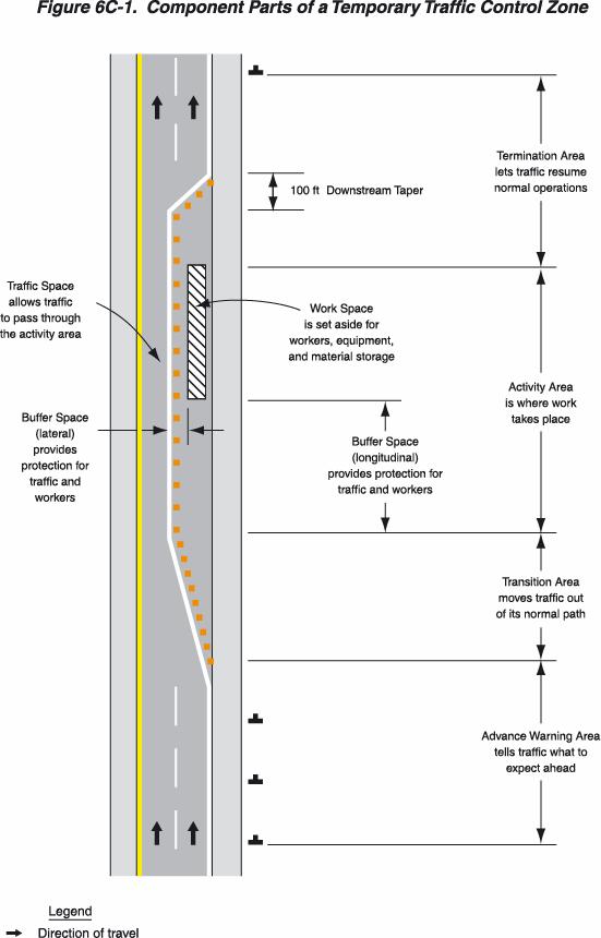
15 An incident area is an area of a highway where temporary traffic controls are imposed by authorized officials in response to a road user incident, natural disaster, or special event. Section 6C.03 Components of Temporary Traffic Control Zones Most temporary traffic control zones are divided into four areas: the advance warning area, the transition area, the activity area, and the termination area. Figure 6C-1 illustrates these four areas. These four areas are described in Sections 6C.04 through 6C.07. Section 6C.04 Advance Warning Area When the work space is within the traveled way, except for short-duration and mobile operations, advance warning should provide a general message that work is taking place, should supply information about highway conditions, and should indicate how motor vehicles can move through the temporary traffic control zone. The advance warning area is the section of highway where road users are informed about the upcoming work zone or incident area. The advance warning area may vary from a single sign or rotating/strobe lights on a vehicle to a series of signs in advance of the temporary traffic control zone activity area. Typical distances for placement of advance warning signs on expressways and freeways should be longer because drivers are conditioned to uninterrupted flow. Therefore, the advance warning sign placement should extend on these facilities as far as 800 m (0.5 mi) or more. On urban streets, the effective placement of the first warning sign in meters (feet) should range from 0.75 to 1.5 times the speed limit in km/h (4 to 8 times the speed limit in mph), with the high end of the range being used when speeds are relatively high. When a single advance warning sign is used (in cases such as low-speed residential streets), the advance warning area can be as short as 30 m (100 ft) if assuming a 25 mph posted speed. When two or more advance warning signs are used on higher-speed streets, such as major arterials, the advance warning area should extend a greater distance (see Table 6C-1). 6C-3
16 Since rural highways are normally characterized by higher speeds, the effective placement of the first warning sign in meters (feet) should be substantially longer from 1.5 to 2.25 times the speed limit in km/h (8 to 12 times the speed limit in mph). Since two or more advance warning signs are normally used for these conditions, the advance warning area should extend 450 m (1,500 ft) or more for open highway conditions (see Table 6C-1). Advance warning may be eliminated when the activity area is sufficiently removed from the road users path so that it does not interfere with the normal flow. Section 6C.05 Transition Area The transition area is that section of highway where road users are redirected out of their normal path. When redirection of the road users normal path is required, they shall be channelized from the normal path to a new path. In mobile operations, the transition area moves with the work space. Transition areas usually involve strategic use of tapers, which because of their importance are discussed separately in detail. Section 6C.06 Activity Area The activity area is the section of the highway where the work activity takes place. It is comprised of the work space, the traffic space, and the buffer space. The work space is that portion of the highway closed to road users and set aside for workers, equipment, and material, and a shadow vehicle if one is used upstream. Work spaces are usually delineated for road users by channelizing devices or, to exclude vehicles and pedestrians, by temporary barriers. The work space may be stationary or may move as work progresses. 6C-4
17 6C-5
18 Table 6C-1. Suggested Advance Warning Sign Spacing Road Classification Posted Speed (MPH) Sign Spacing (Feet) Conventional Highways * * * * * 900 Notes: Expressways or Freeways All Speeds *Distance between signs should be increased to have 1500 feet advance warning. **Distance between signs should be increased to have ½ mile or more advance warning. See Typical Applications** Since there may be several work spaces (some even separated by several kilometers or miles) within the project limits, each work space should be adequately signed to inform road users and reduce confusion. The traffic space is the portion of the highway in which road users are routed through the activity area. The optional buffer space is a lateral and/or longitudinal area that separates road user flow from the work space or an unsafe area, and might provide some recovery space for an errant vehicle. Neither work activity nor storage of equipment, vehicles, or material should occur within a buffer space. Buffer spaces may be positioned either longitudinally or laterally with respect to the direction of road user flow. The activity area may contain one or more lateral or longitudinal buffer spaces. 6C-6
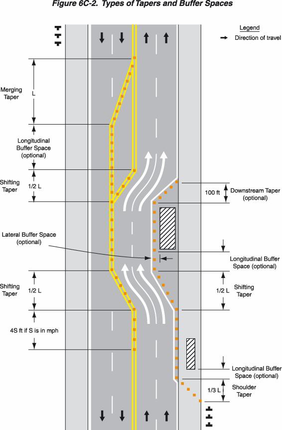
19 A longitudinal buffer space may be placed in the initial portion of a closed lane in advance of a work space. The length of the longitudinal buffer should be determined by engineering judgment. Table 6C-1a may be used as a guide to determine longitudinal buffer space. Table 6C-1a. Longitudinal Buffer Space * Posted speed Speed * (mph) Length (meters) Length (feet) Based upon American Association of state Highway and Transportation Officials (AASHTO) braking distance portion of stopping sight distance for wet and level pavements (A Policy on Geometric Design of Highways and Streets, AASHTO, 1990, p. 120). This AASHTO document also recommends adjustments for the effect of grade on stopping and variation for trucks. The longitudinal buffer space may also be used to separate opposing road user flows that use portions of the same traffic lane, as shown in Figure 6C-2. Typically, the buffer space is formed as a traffic island and defined by channelizing devices. When a formidable device, such as a shadow vehicle or an arrow panel, is placed in such an island, only the area in front of the device functions as a buffer. 6C-7
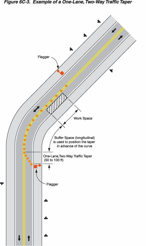
20 The lateral buffer space may be used to separate the traffic space from the work space, as shown in Figures 6C-1 and 6C-2, or such areas as excavations or pavement-edge drop-offs. A lateral buffer space also may be used between two travel lanes, especially those carrying opposing flows. The width of a lateral buffer space should be determined by engineering judgment. When work occurs on a high-volume, highly congested facility, an incident management vehicle storage space may be provided so that emergency vehicles (for example, tow trucks) can respond quickly to road user incidents. If used, an emergency-vehicle storage area should not extend into any portion of the buffer space. Section 6C.07 Termination Area The termination area shall be used to return road users to their normal path. The termination area shall extend from the downstream end of the work area to the END ROAD WORK signs, if posted. An END ROAD WORK sign, a Speed Limit sign, or other signs may be used to inform road users that they can resume normal operations. Section 6C.08 Tapers Tapers may be used in both the transition and termination areas. Whenever tapers are to be used in close proximity to an interchange ramp, crossroads, curves, or other influencing factors, the length of the tapers may be adjusted. Tapers are created by using a series of channelizing devices and/or pavement markings to move traffic out of or into the normal path. Types of tapers are shown in Figure 6C-2. The one-lane, two-way taper is shown in Figure 6C-3. 6C-8
21 6C-9
22 Longer tapers are not necessarily better than shorter tapers (particularly in urban areas characterized by short block lengths, driveways, etc.) because extended tapers tend to encourage sluggish operation and to encourage drivers to delay lane changes unnecessarily. The test concerning adequate lengths of tapers involves observation of driver performance after temporary traffic control plans are put into effect The criteria for determining the taper length (L) is shown in Table 6C-2 and should be the minimum used. Table 6C-3 lists the minimum desirable taper lengths (L) and the suggested maximum spacing of channelizing devices that should be used. The maximum distance in meters (feet) between devices in a taper should not exceed 0.2 times the speed limit in km/h (1.0 times the speed limit in mph). The one-lane, two-way and downstream tapers should have a minimum distance of 100 feet and should have devices spaced at approximately 20 feet. A merging taper requires the longest distance because drivers are required to merge with an adjacent lane of traffic at the prevailing speed. A merging taper should be long enough to enable merging drivers to have adequate advance warning and sufficient length to adjust their speeds and merge into a single lane before the end of the transition. A shifting taper is used when merging is not required, but a lateral shift is needed. When more space is available, a longer than minimum taper distance can be beneficial. Changes in alignment can also be accomplished by using horizontal curves designed for normal highway speeds. A shifting taper should have a length of approximately 0.5 L (see Table 6C-2). A shoulder taper may be beneficial on a high-speed roadway where shoulders are part of the activity area and are closed, or when improved shoulders might be mistaken as a driving lane. In these instances, the same type, but abbreviated, closure procedures used on a normal portion of the roadway can be used. 6C-10
23 If used, shoulder tapers should have a length of approximately 0.33 L (see Table 6C-2). If a shoulder is used as a travel lane, either through practice or during a temporary traffic control activity, a normal merging or shifting taper should be used. A downstream taper may be useful in termination areas to provide a visual cue to the driver that access is available back into the original lane or path that was closed. When used, a downstream taper should have a minimum length of approximately 30 m (100 ft) per lane with devices placed at a spacing of approximately 6.1 m (20 ft). The one-lane, two-way taper is used in advance of an activity area that occupies part of a two-way roadway in such a way that a portion of the road is used alternately by traffic in each direction. Table 6C-2. Taper Length Criteria fortemporary Traffic Control Zones Type of Taper Taper Length (L)* Merging Taper at least L Shifting Taper at least 0.5L Shoulder Taper at least 0.33L One-Lane, Two-Way Traffic Taper at least 100 ft Downstream Taper 100 ft per lane *Formulas for L are as follows: For speed limits of 40 mph or less: L = WS 2 60 For speed limits of 45 mph or greater: L = WS Where: L = taper length in feet W = width of offset in feet S = posted speed limit, or off-peak 85th-percentile speed prior to work starting, or the anticipated operating speed in mph 6C-11
24 Table 6C-3: Merging Taper Lengths and Spacing of Devices Minimum Desirable Taper Lengths ** Suggested Maximum Spacing of Channelizing Devices Posted On a Formula 10 Offset 11 Offset 12 Offset On a taper Speed* Tangent L = WS L = WS * Conventional Roads Only (MPH) ** Taper lengths have been rounded off. L = Length of Taper (Ft.) W = Width of Offset (Ft.) S = Posted Speed (MPH) Traffic typically is controlled by a flagger or temporary traffic signal (if sight distance is limited), or a STOP or YIELD sign. A short taper having a maximum length of 30 m (100 ft) with channelizing devices at approximately 6.1 m (20 ft) spacings should be used to guide traffic into the one-way section. An example of a one-lane, two-way traffic taper is shown in Figure 6C-3. Section 6C.09 Detours and Diversions A detour is a temporary rerouting of road users onto an existing roadway in order to avoid a temporary traffic control zone. Detours should be clearly signed over their entire length so that road users can easily use existing highways to return to the original roadway. A diversion is a temporary rerouting of road users onto a temporary roadway or alignment placed around the work area. 6C-12
25 Section 6C.10 One-Lane, Two-Way Traffic Control When traffic in both directions must use a single lane for a limited distance, movements from each end shall be coordinated. Provisions should be made for alternate one-way movement through the constricted section via methods such as flagger control, a flag transfer, a pilot car, traffic control signals, or stop or yield control. Control points at each end should be chosen to permit easy passing of opposing lanes of vehicles. If traffic on the affected one-lane roadway is not visible from one end to the other, then flagging procedures, a pilot car, or traffic control signal should be used to control opposing traffic flows. At a spot constriction, such as an isolated pavement patch on highways with lower speeds and adequate sight distance, the movement of traffic through one-lane, two-way constrictions tends to be self-regulating. Section 6C.11 Flagger Method of One-Lane, Two-Way Traffic Control When a one-lane, two-way temporary traffic control zone is short enough to allow a flagger to see from one end of the zone to the other, traffic may be controlled by either a single flagger or by a flagger at each end of the section. When a single flagger is used, the flagger should be stationed on the shoulder opposite the constriction or work space, or in a position where good visibility and traffic control can be maintained at all times. When good visibility and traffic control cannot be maintained by one flagger station, traffic should be controlled by a flagger at each end of the section. One of the flaggers should be designated as the coordinator. Flaggers should be able to communicate with each other orally, electronically, or with manual signals. These manual signals should not be mistaken for flagging signals. Section 6C.12 DELETED 6C-13
26 6C-14
27 Section 6C.13 Pilot Car Method of One-Lane, Two-Way Traffic Control A pilot car may be used to guide a queue of vehicles through the temporary traffic control zone or detour. The operation of the pilot vehicle should be coordinated with flagging operations or other controls at each end of the one-lane section. The pilot car should have the name of the contractor or contracting authority prominently displayed. The PILOT CAR FOLLOW ME (G20-4) sign shall be mounted at a conspicuous location on the rear of the vehicle. Section 6C.14 Temporary Traffic Control Signal Method of One-Lane, Two-Way Traffic Control Traffic control signals may be used to control motor vehicle traffic movements in one-lane, two-way temporary traffic control zones (see Figure 6H-12 and Chapter 4G). Section 6C.15 Stop or Yield Control Method of One-Lane, Two-Way Traffic Control STOP or YIELD signs may be used to control traffic on low-volume roads at a one-lane, two-way work zone when drivers are able to see the other end of the one-lane, two-way operation and have sufficient visibility of approaching vehicles. If the STOP or YIELD sign is installed for only one direction, then the STOP or YIELD sign should face road users who are driving on the side of the roadway that is closed for the work activity area. 6C-15
28 6C-16
29 CHAPTER 6D. PEDESTRIAN AND WORKER SAFETY Section 6D.01 Pedestrian Considerations A wide range of pedestrians can be expected at work sites, including the young, old, and disabled (for example, hearing, visual, and mobility). All of these pedestrians need a clearly delineated and usable travel path. The various temporary traffic control provisions for pedestrian and worker safety set forth in Part 6 shall be applied by knowledgeable (for example, trained and/or certified) persons after appropriate evaluation and engineering judgment. Advance notification of sidewalk closures shall be provided. It must be recognized that pedestrians are reluctant to retrace their steps to a prior intersection for a crossing. Adequate provisions should be made for persons with disabilities as determined by an engineering study. There are three considerations in planning for pedestrians in temporary traffic control zones: A. Pedestrians should not be led into direct conflicts with work site vehicles, equipment, and operations. B. Pedestrians should not be led into direct conflicts with main lane traffic moving through or around the work site. C. Pedestrians should be provided with a safe, convenient path that replicates as nearly as practical the most desirable characteristics of the existing sidewalk(s) or a footpath(s). Consideration should be made to separate pedestrian movements from both work site activity and motor vehicle traffic. Pedestrians should be appropriately directed with advance signing that encourages them to cross to the opposite side of the roadway. In urban and suburban areas with high motor vehicle traffic volumes, these signs should be placed at intersections so that pedestrians are not confronted with midblock work sites that will induce them to attempt skirting the work site or making a midblock crossing. 6D-1
30 Figures 6H-28 and 6H-29 show typical temporary traffic control device usage and techniques for pedestrian movement through work zones. When pedestrian movement through or around a work site is necessary, a separate usable footpath without abrupt changes in grade or terrain should be provided. Whenever it is feasible, closing off the work site from pedestrian intrusion may be preferable to channelizing pedestrian traffic along the site with temporary traffic control devices such as cones, tubular markers, barricades and drums, or other suitable fencing. Fencing should not create sight distance restrictions for road users. Fences should not be constructed of materials that would be hazardous if impacted by vehicles. Wooden railing, fencing, and similar systems placed immediately adjacent to motor vehicle traffic should not be used as substitutes for crashworthy temporary traffic barriers. Temporary traffic control devices used to delineate a temporary traffic control zone pedestrian walkway shall be crashworthy and, when struck by vehicles, present a minimum threat to pedestrians, workers, and occupants of impacting vehicles. Ballast for temporary traffic control devices should be kept to the minimum amount needed and should be mounted low to prevent penetration of the vehicle windshield. Movement by work vehicles and equipment across designated pedestrian paths should be minimized and, when necessary, should be controlled by flaggers or temporary traffic control. Staging or stopping of work vehicles or equipment along the side of pedestrian paths should be avoided, since it encourages movement of workers, equipment and materials across the pedestrian path. Access to work space across pedestrian walkways should be minimized because the access often creates unacceptable changes in grade, and rough or muddy terrain, and pedestrians will tend to avoid these areas by attempting nonintersection crossings. 6D-2
31 A canopied walkway may be used to protect pedestrians from falling debris. Covered walkways should be sturdily constructed and adequately lighted for nighttime use. When pedestrian and vehicle paths are rerouted to a closer proximity to each other, consideration should be given to separating them by a temporary traffic barrier. If a temporary traffic barrier is used to shield pedestrians, it should be designed to suit site conditions. Depending on the possible motor vehicle speed and angle of impact, temporary traffic barriers might deflect upon impact by an errant vehicle. Guidance for locating and designing temporary traffic barriers can be found in Chapter 9 of AASHTO s "Roadside Design Guide" (see Section 1A.11). Short intermittent segments of temporary traffic barrier shall not be used because they nullify the containment and redirective capabilities of the temporary traffic barrier, increase the potential for serious injury both to vehicle occupants and pedestrians, and encourage the presence of blunt, leading ends. All upstream leading ends that are present shall be appropriately flared or protected with properly installed and maintained crashworthy cushions. Adjacent temporary traffic barrier segments shall be properly connected in order to provide the overall strength required for the temporary traffic barrier to perform properly. Normal vertical curbing shall not be used as a substitute for temporary traffic barriers when temporary traffic barriers are clearly needed. Temporary traffic barriers or longitudinal channelizing devices may be used to discourage pedestrians from unauthorized movements into the work space. They may also be used to inhibit conflicts with motor vehicle traffic by minimizing the possibility of midblock crossings. One example of a major pedestrian concern is urban and suburban building construction encroaching onto the contiguous sidewalks, which forces pedestrians off the curb into direct conflict with moving vehicles. 6D-3
32 If a high potential exists for vehicle incursions into the pedestrian path, pedestrians should be rerouted or temporary traffic barriers should be installed. Standard temporary traffic control devices can satisfactorily delineate a pedestrian path. Although tape, rope, fencing, or plastic chain strung between devices can help discourage pedestrian movements off the designated pathway, they cannot eliminate them entirely. The extent of pedestrian needs should be determined through engineering judgment for each work zone situation. The highway agency in charge of the temporary traffic control should regularly inspect the activity area so that effective pedestrian temporary traffic control is maintained. Section 6D.02 Worker Considerations Equally as important as the safety of road users traveling through the work zone is the safety of workers. Temporary traffic control zones present temporary and constantly changing conditions that are unexpected by the road user. This creates an even higher degree of vulnerability for workers on or near the roadway. Maintaining work zones with road user flow inhibited as little as possible, and using temporary traffic control devices that get the road user's attention and provide positive direction are of particular importance. The following are the key elements of temporary traffic control management that should be considered to improve worker safety: A. Training - all workers should be trained on how to work next to motor vehicle traffic in a way that minimizes their vulnerability. Workers having specific temporary traffic control responsibilities should be trained in temporary traffic control techniques, device usage, and placement. B. Worker Clothing - workers close to the motor vehicle traveled way should wear bright, highly visible clothing (see Section 6E.02). 6D-4
33 C. Temporary Traffic Barriers - temporary traffic barriers should be placed along the work space depending on factors such as lateral clearance of workers from adjacent traffic, speed of traffic, duration and type of operations, time of day, and volume of traffic. D. Speed Reduction - reducing the speed of motor vehicle traffic, mainly through regulatory speed zoning, funneling, use of law enforcement officials, lane reduction, or flaggers, should be considered. The following are additional elements of temporary traffic control management that may be considered to improve worker safety: A. Shadow Vehicle - in the case of mobile and constantly moving operations, such as pothole patching and striping operations, a shadow vehicle, equipped with appropriate lights, warning signs, and/or a rear-mounted impact attenuator may be used to protect the workers from impacts by errant vehicles. B. Road Closure - if alternate routes are available to handle road users, the road may be closed temporarily. This may also facilitate project completion and thus further reduce worker vulnerability. C. Police Use - in highly vulnerable work situations, particularly those of relatively short duration, police units may be stationed to heighten the awareness of passing motor vehicle traffic and to improve safety through the temporary traffic control zone. D. Lighting - for nighttime work, the work zone and approaches may be lighted. E. Special Devices - judicious use of special warning and control devices may be helpful for certain difficult work zone situations. These include rumble strips, changeable message signs, hazard identification beacons, flags, and warning lights. Intrusion warning devices may be used to alert workers to the approach of errant vehicles. However, misuse or overuse of special devices or techniques may lessen their effectiveness. 6D-5
34 6D-6
35 Section 6E.01 Qualifications for Flaggers CHAPTER 6E. FLAGGER CONTROL A flagger shall be a person who provides temporary traffic control. Because they are responsible for road user safety, and because they make frequent contact with the public, flaggers should have the following minimum qualifications: A. Sense of responsibility for the safety of the public and the workers; B. Adequate training in safe temporary traffic control practices; C. Average intelligence; D. Good physical condition, including sight, mobility, and hearing; E. Mental alertness and the ability to react in an emergency; F. Courteous but firm manner; and G. Neat appearance. Section 6E.02 High-Visibility Clothing For daytime work, the flagger's vest, shirt, or jacket shall be either orange, yellow, yellow-green, or a fluorescent version of these colors. For nighttime work, similar outside garments shall be retroreflective. The retroreflective material shall be either orange, yellow, white, silver, yellow-green, or a fluorescent version of these colors, and shall be visible at a minimum distance of 300 m (1,000 ft). The retroreflective clothing shall be designed to clearly identify the wearer as a person. When uniformed law enforcement officers are used, high-visibility clothing as described above should be worn by the law enforcement officer. 6E-1
36 Section 6E.03 Hand-Signaling Devices Hand-signaling devices, such as STOP/SLOW paddles, lights, and red flags, are used to control road users through temporary traffic control zones. The STOP/SLOW paddle should be the primary and preferred hand-signaling device because the STOP/SLOW paddle gives road users more positive guidance than red flags. Use of flags should be limited to emergency situations or at low-speed and/or low volume location which can be best controlled by a single flagger. The STOP/SLOW paddle shall have an octagonal shape on a rigid handle. STOP/SLOW paddles shall be at least 450 mm (18 in) wide with letters at least 150 mm (6 in) high and should be fabricated from light semirigid material. The background of the STOP face shall be red with white letters and border. The background of the SLOW face shall be orange with black letters and border. When used at night, the STOP/SLOW paddle shall be retroreflectorized. The STOP/SLOW paddle may be modified to improve conspicuity by incorporating white flashing lights. Two lights may be installed and centered vertically above and below the STOP legend, or centered horizontally on either side of the STOP legend. Instead of the above two-light arrangement, one light may be centered below the STOP legend. Flags, when used, shall be a minimum of 600 mm (24 in) square, made of a good grade of red material, and securely fastened to a staff that is approximately 900 mm (36 in) in length. The free edge of a flag should be weighted so the flag will hang vertically, even in heavy winds. When used at nighttime, flags shall be retroreflectorized red. 6E-2
37 Section 6E.04 Flagger Procedures The use of paddles and flags by flaggers are illustrated in Figure 6E-1. The following methods of signaling with paddles shall be used: A. To stop road users, the flagger shall face road users and aim the STOP paddle face toward road users in a stationary position with the arm extended horizontally away from the body. The free arm shall be held with the palm of the hand above shoulder level toward approaching traffic. B. To direct stopped road users to proceed, the flagger shall face road users with the SLOW paddle face aimed toward road users in a stationary position with the arm extended horizontally away from the body. The flagger shall motion with the free hand for road users to proceed. C. To alert or slow traffic, the flagger shall face road users with the SLOW paddle face aimed toward road users in a stationary position with the arm extended horizontally away from the body. To further alert or slow traffic, the flagger holding the SLOW paddle face toward road users may motion up and down with the free hand, palm down. The following methods of signaling with a flag shall be used: A. To stop road users, the flagger shall face road users and extend the flag staff horizontally across the road users' lane in a stationary position so that the full area of the flag is visibly hanging below the staff. The free arm shall be held with the palm of the hand above the shoulder level toward approaching traffic. B. To direct stopped road users to proceed, the flagger shall stand parallel to the road user movement and with flag and arm lowered from the view of the road users, and shall motion with the free hand for road users to proceed. Flags shall not be used to signal road users to proceed. 6E-3
38 6E-4
39 C. To alert or slow traffic, the flagger shall face road users and slowly wave the flag in a sweeping motion of the extended arm from shoulder level to straight down without raising the arm above a horizontal position. The flagger shall keep the free hand down. Section 6E.05 Flagger Stations Flagger stations shall be located far enough in advance of the work space so that approaching road users will have sufficient distance to stop before entering the work space. Guidelines for determining the distance of the flagger station in advance of the work space are shown in Table 6E-1. An example of a flagger station in a one-lane, two-way traffic taper is shown in Figure 6C-3. The distances shown in Table 6E-1 may be increased for downgrades and other conditions that affect stopping distance. Flagger stations should be preceded by proper advance warning signs. At night, flagger stations should be illuminated. The flagger should stand either on the shoulder adjacent to the road user being controlled or in the closed lane prior to stopping road users. A flagger should only stand in the lane being used by moving road users after road users have stopped. The flagger should be clearly visible to the first approaching road user at all times. The flagger also should be visible to other road users. The flagger should be stationed sufficiently in advance of the workers to warn them (for example, with audible warning devices such as horns, whistles, etc.) of approaching danger by out-of-control vehicles. The flagger should stand alone, never permitting a group of workers to congregate around the flagger station. At a spot constriction, the flagger may have to take a position on the shoulder opposite the closed section in order to operate effectively. Table 6E-1 may be used to determine the visibility distance for road users approaching the flagger. 6E-5
40 At spot lane closures where adequate sight distance is available for the safe handling of traffic, the use of one flagger may be sufficient. Table 6E-1. Distance of Flagger Station in Advance of the Work Space Speed* (mph) Distance (ft) *Posted speed, off-peak 85 th -percentile speed prior to work starting, or the anticipated operating speed. 6E-6
41 CHAPTER 6F. TEMPORARY TRAFFIC CONTROL ZONE DEVICES Section 6F.01 Types of Devices The design and application of temporary traffic control devices used in temporary traffic control zones should consider the needs of all road users. Crashworthiness and crash testing information on devices described in Part 6 are found in AASHTO s "Roadside Design Guide" (see Section 1A.11). Traffic control devices shall be defined as all signs, signals, markings, and other devices used to regulate, warn, or guide traffic, placed on, over, or adjacent to a street, highway, pedestrian facility, or bikeway by authority of a public body or official having jurisdiction. All traffic control devices used on street and highway construction, maintenance, utility, or incident management operations shall conform to the applicable provisions of this Manual. Where the color orange is required, fluorescent red-orange or fluorescent yellow-orange colors may also be used. The fluorescent versions of orange provide higher conspicuity than standard orange, especially during twilight. Section 6F.02 General Characteristics of Signs Temporary traffic control zone signs convey both general and specific messages by means of words or symbols and have the same three categories as all road user signs: regulatory, warning, and guide. 6F-1
42 The colors for regulatory signs shall follow the Standards for regulatory signs in Table 2A-4 and Chapter 2B. Warning signs in temporary traffic control zones shall have a black legend on an orange background, except for the Railroad Advance Warning (W10-1) sign which shall have a black message and border on a yellow background, and except for signs that are permitted in Part 2 to have yellow or fluorescent yellow-green backgrounds. Colors for guide signs shall follow the Standards in Table 2A-4 and Chapter 2D, except for guide signs as noted in Section 6F.47. Existing warning signs that are still applicable may remain in place. In order to maintain the systematic use of yellow or fluorescent yellow-green background for pedestrian, bicycle, and school warning signs in a jurisdiction, the yellow or fluorescent yellowgreen background for pedestrian, bicycle, and school warning signs may be used in temporary traffic control zones. Standard orange flags or flashing warning lights may be used in conjunction with signs. When standard orange flags or flashing warning lights are used in conjunction with signs, they shall not block the sign face. The dimensions of signs shown in Part 6 are for standard sizes, which may be increased wherever necessary for greater legibility or emphasis. Deviations from standard sizes as prescribed herein shall be in 150 mm (6 in) increments. Sign design details are contained in the "Standard Highway Sign Designs for Texas" book. All signs used at night shall be either retroreflective with a material that has a smooth, sealed outer surface or illuminated to show the same shape and similar color both day and night. 6F-2
43 Sign illumination may be either internal or external. Street, highway, or strobe lighting does not constitute external sign illumination. Signs may be made of rigid or flexible material. Section 6F.03 Sign Placement Signs should be located on the right side of the roadway unless otherwise specified in this Manual. Where special emphasis is needed, signs may be placed on both the left and right sides of the roadway. Signs mounted on portable supports may be placed within the roadway itself. Signs may also be mounted on or above barricades. Guidelines for height and lateral clearance of temporary post-mounted signs are shown in Figure 6F-1. Post-mounted signs installed shall be mounted at a height at least 2.1 m (7 ft), measured from the bottom of the sign to the near edge of the travel way. Additionally, the height of the sign from the ground directly below the sign to the bottom of the sign shall be 2.1 m (7 ft). Signs mounted on barricades and barricade/sign combinations shall be crashworthy. Neither portable nor permanent sign supports should be located on sidewalks, bicycle lanes, or areas designated for pedestrian or bicycle traffic. 6F-3
44 6F-4
45 A 2.1 m (7 ft) mounting height may be used in rural areas for increased visibility. The height to the bottom of a secondary sign mounted below another sign may be 0.3 m (1 ft) less than the appropriate height specified above. Except as noted in the Option, signs mounted on portable supports may be used for short-term, short-duration and mobile conditions. The R9-8 through R9-11a series, R11 series, CW1-6 through CW1-8 series, M4-10, E5-1, or other similar type signs may be used on portable supports for longer than 3 days. Methods of mounting signs other than on posts are illustrated in Figure 6F-2. Signs mounted on Type III barricades should not cover more than 50 percent of the top two rails or 33 percent of the total area of the three rails. Sign supports shall be crashworthy. Large signs having an area exceeding 5 square meters (50 square feet) that are installed on multiple breakaway posts shall be mounted a minimum of 2.1 m (7 ft) above the ground. Signs mounted on barricades, or other portable supports, shall be no less than 0.3 m (1 ft) above the traveled way. Vehicle mounted signs shall have the bottom of the sign at a minimum height of 1.2 m (4 ft) above the pavement. Signs shall be covered or removed when work is not in progress. For mobile operations, a sign may be mounted on a work vehicle, a shadow vehicle, or a trailer stationed in advance of the temporary traffic control zone or moving along with it. The work vehicle, and/or the shadow vehicle may have an impact attenuator. Sign display may be mounted on a trailer. 6F-5
46 6F-6
47 Section 6F.04 Sign Maintenance Signs shall be properly maintained for cleanliness, visibility, and correct positioning. Signs that have lost significant legibility shall be promptly replaced. Section 6F.05 Regulatory Sign Authority Regulatory signs inform road users of traffic laws or regulations and indicate the applicability of legal requirements that would not otherwise be apparent. Regulatory signs shall be authorized by the public agency or official having jurisdiction and shall conform with Chapter 2B. Section 6F.06 Regulatory Sign Design Temporary traffic control regulatory signs shall conform to the Standards for regulatory signs presented in Part 2 and in the "Standard Highway Sign Designs for Texas" book. Regulatory signs are generally rectangular with a black legend and border on a white background. Exceptions include the STOP, YIELD, DO NOT ENTER, WRONG WAY, and ONE WAY signs. The ONE WAY sign may be either a horizontal or vertical rectangular sign. Section 6F.07 Regulatory Sign Applications If a temporary traffic control zone requires regulatory measures different from those existing, the existing permanent regulatory devices shall temporarily be removed or covered and superseded by the appropriate temporary regulatory signs. This change shall be made in conformance with applicable ordinances or statutes of the jurisdiction as well as comply with the "Standard Highway Sign Designs for Texas". 6F-7
48 6F-8
49 6F-9
50 6F-10
51 Section 6F.08 ROAD (STREET) CLOSED Sign (R11-2) The ROAD (STREET) CLOSED (R11-2) sign should be used when the roadway is closed to all road users except contractors' equipment or officially authorized vehicles. The R11-2 sign should be accompanied by appropriate warning and detour signing. The words BRIDGE OUT (or BRIDGE CLOSED) may be substituted for ROAD (STREET) CLOSED where applicable. The ROAD (STREET) CLOSED sign should be installed at or near the center of the roadway on or above a Type III barricade that closes the roadway (see Section 6F.60). The ROAD (STREET) CLOSED sign shall not be used where road user flow is maintained or where the actual closure is some distance beyond the sign. Section 6F.09 Local Traffic Only Signs (R11-3a, R11-4) The Local Traffic Only signs should be used where road user flow detours to avoid a closure some distance beyond the sign, but where local road users can use the roadway to the point of closure. These signs should be accompanied by appropriate warning and detour signing. In rural applications, the Local Traffic Only sign should have the legend ROAD CLOSED XX KM (MILES) AHEAD, LOCAL TRAFFIC ONLY (R11-3a). In urban areas, the legend ROAD (STREET) CLOSED TO THRU TRAFFIC (R11-4) or ROAD CLOSED, LOCAL TRAFFIC ONLY may be used. The words BRIDGE OUT (or BRIDGE CLOSED) may be substituted for the words ROAD (STREET) CLOSED on the R11-3a or R11-4 sign where applicable. 6F-11
52 Section 6F.10 Weight Limit Signs (R12-1, R12-2, R12-5) A Weight Limit sign, which shows the gross weight or axle weight that is permitted on the roadway or bridge, shall be consistent with State or local regulations and shall not be installed without the approval of the authority having jurisdiction over the highway. When weight restrictions are imposed, a marked detour shall be provided for vehicles weighing more than the posted limit. Section 6F.11 STAY IN LANE Sign (R4-9) A STAY IN LANE (R4-9) sign may be used where a multilane shift has been incorporated as part of the temporary traffic control on a highway to direct road users around road work that occupies part of the roadway on a multilane highway. Section 6F.12 PEDESTRIAN CROSSWALK Sign (R9-8) The PEDESTRIAN CROSSWALK (R9-8) sign may be used to indicate where a temporary crosswalk has been established. Section 6F.13 SIDEWALK CLOSED Signs (R9-9, R9-10, R9-11, R9-11a) SIDEWALK CLOSED signs should be used where pedestrian flow is restricted or rerouted by work activities. The SIDEWALK CLOSED (R9-9) sign should be installed at the beginning of the closed sidewalk, at the intersections preceding the closed sidewalk, and elsewhere along the closed sidewalk as needed. The SIDEWALK CLOSED, (ARROW) USE OTHER SIDE (R9-10) sign should be installed at the beginning of the restricted sidewalk when a parallel sidewalk exists on the other side of the roadway. The SIDEWALK CLOSED AHEAD, (ARROW) CROSS HERE (R9-11) sign should be used to indicate to pedestrians that sidewalks beyond the sign are closed and to direct them to open crosswalks, sidewalks, or other travel paths. 6F-12
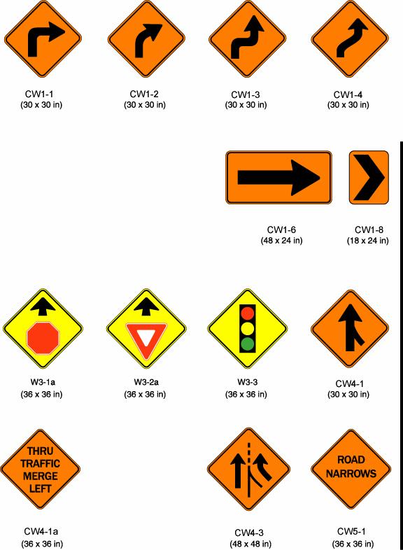
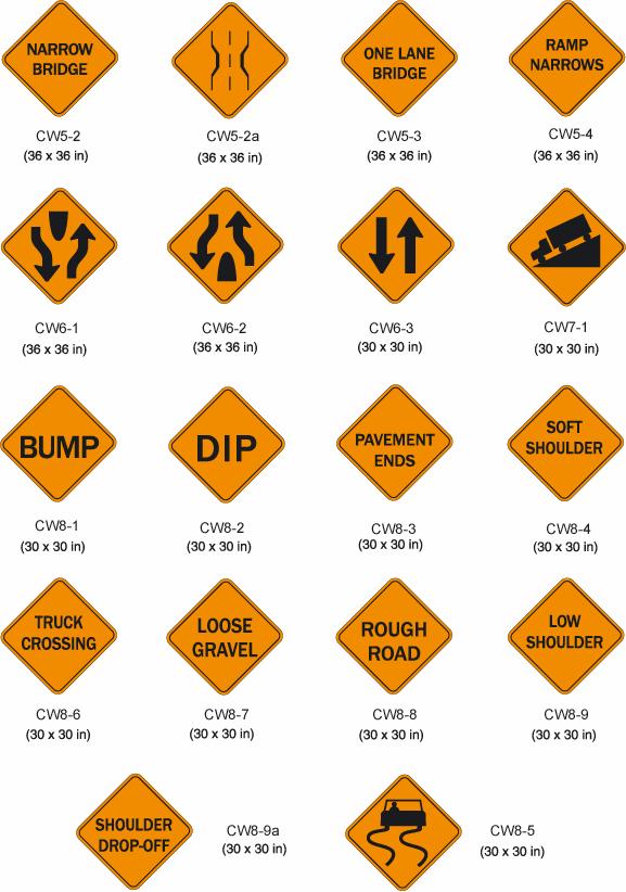
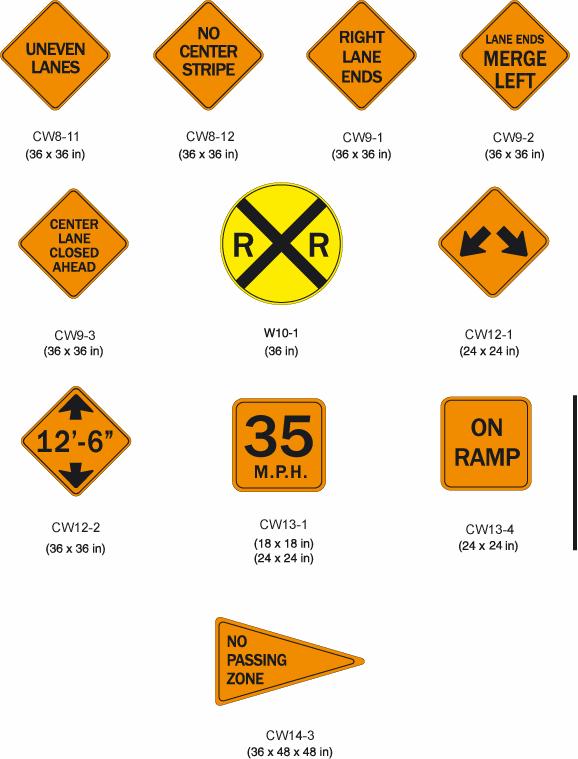
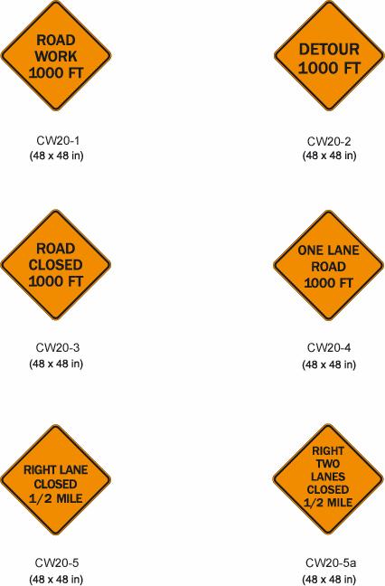
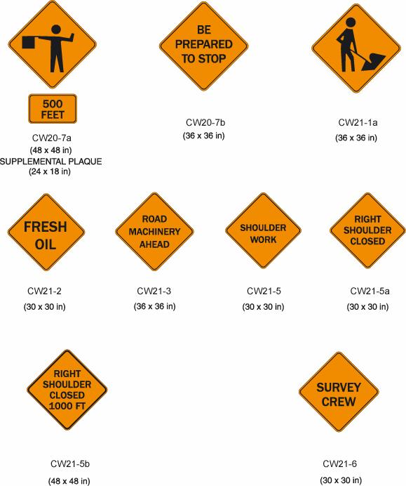
53 The SIDEWALK CLOSED, (ARROW) CROSS HERE (R9-11a) sign should be installed just beyond the point to which pedestrians are being redirected. These signs are typically mounted on a barricade to encourage compliance. Section 6F.14 Special Regulatory Signs Special regulatory signs may be used based on engineering judgment consistent with regulatory requirements. Regulatory speed limits are established by law or regulation. Special regulatory signs should conform to the general requirements of color, shape, and alphabet size and series. The sign message should be brief, legible, and clear. Section 6F.15 Warning Sign Function, Design, and Application Temporary traffic control zone warning signs notify road users of specific situations or conditions on or adjacent to a roadway that might not otherwise be apparent. Temporary traffic control warning signs shall conform to the Standards for warning signs presented in Part 2 and in the "Standard Highway Sign Designs for Texas" book. Except as noted in the Option below, temporary traffic control warning signs shall be diamond-shaped with a black symbol or message and border on an orange background, except for the W3-1a, W3-2a, W3-3 and W10-1 signs which shall have a black message and border on a yellow background, and except for signs that are permitted in Part 2 to have yellow or fluorescent yellow-green backgrounds. Mounting or space considerations may justify a change from the standard diamond shape. In emergencies, available warning signs having yellow backgrounds may be used if orange signs are not at hand. 6F-13
54 6F-14
55 6F-15
56 6F-16
57 6F-17
58 6F-18
59 6F-19
60 6F-20
CHAPTER 6H. TYPICAL APPLICATIONS
 Section 6H.01 Typical Applications Support: CHAPTER 6H. TYPICAL APPLICATIONS Chapter 6G contains discussions of typical temporary traffic control activities. Chapter 6H presents typical applications for
PART 6. TEMPORARY TRAFFIC CONTROL CHAPTER 6A. GENERAL
 2012 Edition Page 623 Section 6A.01 General PART 6. TEMPORARY TRAFFIC CONTROL CHAPTER 6A. GENERAL 01 Whenever the acronym TTC is used in Part 6, it refers to temporary traffic control. 02 The needs and
MUTCD Part 6G: Type of Temporary Traffic Control Zone Activities
 MUTCD Part 6G: Type of Temporary Traffic Control Zone Activities 6G.01 Typical Applications Each temporary traffic control (TTC) zone is different. Many variables, such as location of work, highway type,
(This page left intentionally blank)
") (This page left intentionally blank) 2011 Edition - Revision 2 Page 569 Section 6A.01 General PART 6 TEMPORARY TRAFFIC CONTROL CHAPTER 6A. GENERAL 01 Whenever the acronym TTC is used in Part 6, it refers
(This page left intentionally blank) 2011 Edition - Revision 2 Page 569 Section 6A.01 General PART 6 TEMPORARY TRAFFIC CONTROL CHAPTER 6A. GENERAL 01 Whenever the acronym TTC is used in Part 6, it refers
MUTCD Part 6: Temporary Traffic Control
 MUTCD Part 6: Temporary Traffic Control OMUTCD English units are preferred. OHIO MANUAL OF UNIFORM TRAFFIC CONTROL DEVICES TABLE OF CONTENTS PREFACE INTRODUCTION TABLE OF CONTENTS PART 1. GENERAL Chapter
Developed by: The American Traffic Safety Services Association (ATSSA) 15 Riverside Parkway, Suite 100 Fredericksburg, VA
 15 Riverside Parkway, Suite 100 Fredericksburg, VA") Addendum Developed by: The American Traffic Safety Services Association (ATSSA) 15 Riverside Parkway, Suite 100 Fredericksburg, VA 22406-1022 800-272-8772 This material is based upon work supported by
Addendum Developed by: The American Traffic Safety Services Association (ATSSA) 15 Riverside Parkway, Suite 100 Fredericksburg, VA 22406-1022 800-272-8772 This material is based upon work supported by
DEFINITIONS Activity Area - Advance Warning Area Advance Warning Sign Spacing Advisory Speed Approach Sight Distance Attended Work Space
 DEFINITIONS Activity Area - that part of a TTC zone activity area where the work actually takes place. It consists of the work space, traffic space and one or more buffer spaces. Advance Warning Area -
CHAPTER 6H. TYPICAL APPLICATIONS
 2006 Edition Page 6H-1 CHAPTER 6H. TYPICAL APPLICATIONS Section 6H.01 Typical Applications Support: Whenever the acronym TTC is used in this Chapter, it refers to temporary traffic control. Standard: The
Including Revision 1 dated May 2012 and Revision 2 dated May 2012
 Including Revision 1 dated May 2012 and Revision 2 dated May 2012 Page 634 2009 Edition Notes for Figure 6H-1 Typical pplication 1 Work eyond the Shoulder 1. If the work space is in the median of a divided
Appendix Work Zone Traffic Control
 ppendix Work Zone Traffic Control The purpose of this appendix is to present basic guidelines for work zone traffic control and to supplement the Highway Work Zone Safety Checklist. This appendix presents
(This page left intentionally blank)
") (This page left intentionally blank) 2011 Edition - Revision 1 Page 553 Section 5A.01 Function CHAPTER 5A. GENERAL 01 A low-volume road shall be defined for this Part of the Manual as follows: A. A low-volume
(This page left intentionally blank) 2011 Edition - Revision 1 Page 553 Section 5A.01 Function CHAPTER 5A. GENERAL 01 A low-volume road shall be defined for this Part of the Manual as follows: A. A low-volume
CHAPTER 6D. PEDESTRIAN AND WORKER SAFETY Section 6D.01 Pedestrian Considerations
 April 2015 Page 6D-1 CHAPTER 6D. PEDESTRIAN AND WORKER SAFETY Section 6D.01 Pedestrian Considerations 01 A wide range of pedestrians might be affected by TTC zones, including the young, elderly, and people
STREET and UTILITY REPAIRS WORK AREA PROTECTION GUIDE
 STREET and UTILITY REPAIRS WORK AREA PROTECTION GUIDE May 2006 Street and Utility Repairs Work Area Protection Guide TABLE OF CONTENTS 1. Introduction... 1 2. Typical Applications... 11 2.1 Use of Hand-Signaling
TRAFFIC CONTROL DEVICES FOR LOW VOLUME ROADS
 PART 5. TRAFFIC CONTROL DEVICES FOR LOW VOLUME ROADS TABLE OF CONTENTS Chapter 5A. GENERAL Page Section 5A.1 Function............................................................... 5A-1 5A.2 Application............................................................
PART 5. TRAFFIC CONTROL DEVICES FOR LOW-VOLUME ROADS TABLE OF CONTENTS
 2005 Edition Page TC5-1 PART 5. TRAFFIC CONTROL DEVICES FOR LOW-VOLUME ROADS TABLE OF CONTENTS CHAPTER 5A. Section 5A.01 Section 5A.02 Section 5A.03 Section 5A.04 CHAPTER 5B. GENERAL Page Function...5A-1
2017 Changes to the 2011 MMUTCD January 2017
 2017 Changes to the 2011 MMUTCD January 2017 The design for the Weight Limit symbol sign (R12-5) has been modified to show a threeunit vehicle as the third line of the regulatory weight limit sign. This
TEMPORARY TRAFFIC CONTROL
 (MI) PART 6 TEMPORARY TRAFFIC CONTROL CHAPTER 6A GENERAL Section 6A.01 General... 547 CHAPTER 6B FUNDAMENTAL PRINCIPLES... 549 CHAPTER 6C TEMPORARY TRAFFIC CONTROL ELEMENTS...551............ 554... 554...
CHAPTER 1 STANDARD PRACTICES
 CHAPTER 1 STANDARD PRACTICES OBJECTIVES 1) Functions and Limitations 2) Standardization of Application 3) Materials 4) Colors 5) Widths and Patterns of Longitudinal Pavement Marking Lines 6) General Principles
TEMPORARY TRAFFIC CONTROL GUIDELINES FOR HIGHWAY-RAIL GRADE CROSSINGS
 TEMPORARY TRAFFIC CONTROL GUIDELINES FOR HIGHWAY-RAIL GRADE CROSSINGS 1.0 INTRODUCTION 1.1 Purpose The Southern California Regional Rail Authority (SCRRA) is the designated track owner of the Metrolink
Figure 3B-1. Examples of Two-Lane, Two-Way Marking Applications
 Figure 3B-1. Examples of Two-Lane, Two-Way Marking Applications A - Typical two-lane, two-way marking with passing permitted in both directions B - Typical two-lane, two-way marking with no-passing zones
GUIDELINES FOR EMERGENCY TRAFFIC CONTROL
 GUIDELINES FOR EMERGENCY TRAFFIC CONTROL TABLE OF Contents Page Introduction...1 Chapter 6I of the 2009 MUTCD...2 Reason for Control...6 Components of Incident Management Area...7 Traffic Control Devices
Temporary Traffic Control for Highway Work Zones
 Temporary Traffic Control for Highway Work Zones MONTHLY DELMARVA MISS UTILITY MEMBER MEETING MARCH 20, 2014 PRESENTED BY: Adam Weiser, P.E. PTOE Safety Programs Manager Delaware Department of Transportation
NOT TO SCALE PUBLIC WORKS STANDARD DETAILS CURB DETAILS DATE: MARCH 2013 FILE NAME: CURB.DWG
 NOT TO SCALE PUBLIC WORKS STANDARD DETAILS CURB DETAILS DATE: MARCH 2013 FILE NAME: CURB.DWG NOT TO SCALE PUBLIC WORKS STANDARD DETAILS SIDEWALK RAMPS DATE: MARCH 2013 FILE NAME: SIDEWALK RAMPS.DWG NOT
CW20-1D 48" X 48" (Flags- See note 1) G " X 24" (See note 2)
 G X 24 (See note 2)") CK: DW: CK: x for mph or less mph devices may be omitted if the work area is a minimum of from the nearest traveled way. (See notes 4 & 5) x for mph or less Work Space mph x for mph or less mph (See notes
CK: DW: CK: x for mph or less mph devices may be omitted if the work area is a minimum of from the nearest traveled way. (See notes 4 & 5) x for mph or less Work Space mph x for mph or less mph (See notes
Edison Electric Institute. Work Zone Safety October 4-7, 2009
 Edison Electric Institute Work Zone Safety October 4-7, 2009 1 Your Presenter Mike Kelly Fire Department Battalion Chief (Retired 7/05) Member NCUTCD (Chapter 6) Director/Owner of START Group Consultant
Section 3A.04 Colors. Section 3B.10 Approach Markings for Obstructions
 Section 3A.04 Colors Markings shall be yellow, white, red, or blue, or purple. The colors for markings shall conform to the standard highway colors. Black in conjunction with one of the above colors shall
Accommodating Pedestrians in the Work Zone
 Accommodating Pedestrians in the Work Zone Guidance for Section C Plan Preparers Some impacts cannot be avoided and those impacts apply to residents, businesses, motorists, and pedestrians alike. However,
CHAPTER 2G. PREFERENTIAL AND MANAGED LANE SIGNS
 2011 Edition - Revision 2 Page 275 Section 2G.01 Scope CHAPTER 2G. PREFERENTIAL AND MANAGED LANE SIGNS 01 Preferential lanes are lanes designated for special traffic uses such as high-occupancy vehicles
ADA on Construction. Guidance for Section C Plan Preparers
 ADA on Construction Guidance for Section C Plan Preparers Some impacts cannot be avoided and those impacts apply to residents, businesses, motorists, and pedestrians alike. However, good planning can minimize
New Trends In Temporary Traffic Control (TTC) Spring Occupational Safety & Health Committee Conference Philadelphia, PA
 Spring Occupational Safety & Health Committee Conference Philadelphia, PA") New Trends In Temporary Traffic Control (TTC) Spring Occupational Safety & Health Committee Conference Philadelphia, PA Michael Kelly Work history - Fire service member of 30 years (retired at the rank
New Trends In Temporary Traffic Control (TTC) Spring Occupational Safety & Health Committee Conference Philadelphia, PA Michael Kelly Work history - Fire service member of 30 years (retired at the rank
PART 10. TRAFFIC CONTROLS FOR HIGHWAY-LIGHT RAIL TRANSIT GRADE CROSSINGS TABLE OF CONTENTS
 Part 10. Traffic Controls for Highway-Light Rail Transit Grade Crossings Page 10TC-1 PART 10. TRAFFIC CONTROLS FOR HIGHWAY-LIGHT RAIL TRANSIT GRADE CROSSINGS TABLE OF CONTENTS CHAPTER 10A. GENERAL..........................................
2003 Edition Page 6F-1
 2003 Edition Page 6F-1 CHAPTER 6F. TEMPORARY TRAFFIC CONTROL ZONE DEVICES Section 6F.01 Types of Devices Whenever the acronym TTC is used in this Chapter, it refers to temporary traffic control. The needs
WORK ZONE TRAFFIC CONTROL PROCEDURES
 WORK ZONE SETUP / REMOVAL WORK ZONE TRAFFIC CONTROL PROCEDURES When installing a work zone, install the advance warning signs on all approaches prior to installing the traffic control devices. Perform
Printed copies of this document may not be current. Refer to SafetyNet (Domino.Doc) for the official, controlled version.
 for the official, controlled version.") SASKPOWER TRAFFIC CONTROL PLANNING GUIDELINES INTRODUCTION page 3 DEFINITIONS page 3 PLANNING AND PREPARATION page 6 Pedestrian Safety within an Active Work Area page 7 Excavations page 8 Partial Lane
SASKPOWER TRAFFIC CONTROL PLANNING GUIDELINES INTRODUCTION page 3 DEFINITIONS page 3 PLANNING AND PREPARATION page 6 Pedestrian Safety within an Active Work Area page 7 Excavations page 8 Partial Lane
Traffic Control Inspection Checklist Segment:
 Traffic Control Inspection Checklist Segment: Simon Contractors Simon Contractors Originator: Description Reviewed by: Initials Date Distribution: Traffic Quality Manager, Site Assistant Traffic Manager
SECTION TRAFFIC REGULATIONS
 SECTION 01550 TRAFFIC REGULATIONS PART 1 - GENERAL 1.01 OBJECTIVES A. The Contractor shall provide for safe movement of vehicular, bicycle and pedestrian traffic, including persons with disabilities in
Guide for Law Enforcement Personnel in Work Zones
 Guide for Law Enforcement Personnel in Work Zones Table of Contents Introduction........................... 3 Roles and Responsibilities................ 5 Most Common Law Enforcement Services in Work
CHAPTER 3A. GENERAL PAGE CHAPTER 3B. PAVEMENT AND CURB MARKINGS PAGE
 Virginia Supplement to the 2009 MUTCD Revision 1 Page TC-3-1 PART 3. MARKINGS CHAPTER 3A. GENERAL PAGE Section 3A.01 Functions and Limitations Section 3A.02 Standardization of Application Section 3A.03
Recommended Roadway Plan Section 2 - Land Development and Roadway Access
 Recommended Roadway Plan Section 2 - Land Development and Roadway Access SECTION 2 Land Development and Roadway Access 2.1 Land Use and Access Management The Federal Highway Administration (FHWA) defines
CURBSIDE ACTIVITY DESIGN
 5 CURBSIDE ACTIVITY DESIGN This chapter provides design guidance for separated bike lanes adjacent to curbside activities including parking, loading and bus stops. Typical configurations are presented
WORK ZONE TRAFFIC CONTROL & SAFETY
 WORK ZONE TRAFFIC CONTROL & SAFETY Purpose of Temporary Traffic Control 1. Warn motorists and pedestrians of hazards. 2. Advise proper travel path. 3. Delineate areas not to be used. 4. Separate the travel
MUTCD Part 6D: Pedestrian and Worker Safety
 MUTCD Part 6D: Pedestrian and Worker Safety Section 6D.01 Pedestrian and Worker Safety The needs and control of all road users (motorists, bicyclists, and pedestrians) within the highway, including persons
5. RUNNINGWAY GUIDELINES
 5. RUNNINGWAY GUIDELINES These guidelines should be considered collectively when making runningway decisions. A runningway is the linear component of the transit system that forms the right-of-way reserved
CHAPTER 6G. TYPE OF TEMPORARY TRAFFIC CONTROL ZONE ACTIVITIES Section 6G.01 Typical Applications
 May 20, 2011 DRAFT 6G-1 CHAPTER 6G. TYPE OF TEMPORARY TRAFFIC CONTROL ZONE ACTIVITIES Section 6G.01 Typical Applications 01 Each TTC zone is different. Many variables, such as location of work, highway
Access Location, Spacing, Turn Lanes, and Medians
 Design Manual Chapter 5 - Roadway Design 5L - Access Management 5L-3 Access Location, Spacing, Turn Lanes, and Medians This section addresses access location, spacing, turn lane and median needs, including
Traffic Control Devices
 533372 Highway Engineering Traffic Control Devices Traffic Control Devices o The media by which traffic engineers communicate with drivers o Every traffic law, regulation, or operating instruction must
Sign Designs and Markings Manual (TEM 295-2) Page 8-3
 Page 8-3") Sign Designs and Markings Manual (TEM 295-2) Page 8-3 TEMPORARY TRAFFIC CONTROL SIGNS INDEX Regulatory Signs R1-1 STOP R1-2 YIELD R1-2a TO ONCOMING TRAFFIC R2-1 SPEED LIMIT R2-H2a VEHICLES OVER 4 TONS
Sign Designs and Markings Manual (TEM 295-2) Page 8-3 TEMPORARY TRAFFIC CONTROL SIGNS INDEX Regulatory Signs R1-1 STOP R1-2 YIELD R1-2a TO ONCOMING TRAFFIC R2-1 SPEED LIMIT R2-H2a VEHICLES OVER 4 TONS
TRAFFIC CONTROL DEVICES
 TRAFFIC CONTROL DEVICES SIGNS Temporary traffic control work zone signs include regulatory, warning and guide signs utilized to provide regulations, warnings and guidance information to road users impacted
INTERSECTIONS AT GRADE INTERSECTIONS
 INTERSECTIONS 1 AT GRADE INTERSECTIONS INTERSECTIONS INTERSECTIONS = INTERRUPTED FACILITIES Definitions and key elements An intersection is defined as an area where two or more roadways join or cross.
Sign Design Manual (TEM 295-2)
") TEMPORARY TRAFFIC CONTROL SIGNS INDEX Regulatory Signs R1-1 R-1 STOP R1-2 R-2 YIELD R1-2a R-2A TO ONCOMING TRAFFIC R4-1 R-33 DO NOT PASS R4-2 R-34 PASS WITH CARE R4-3 R-35 SLOWER TRAFFIC KEEP RIGHT R4-9
TEMPORARY TRAFFIC CONTROL SIGNS INDEX Regulatory Signs R1-1 R-1 STOP R1-2 R-2 YIELD R1-2a R-2A TO ONCOMING TRAFFIC R4-1 R-33 DO NOT PASS R4-2 R-34 PASS WITH CARE R4-3 R-35 SLOWER TRAFFIC KEEP RIGHT R4-9
REVOCABLE PERMIT FOR STREET BANNER APPLICATION PACKAGE
 Development Engineering 300 Richards Blvd., 3rd Floor Sacramento, CA 95811 Engineering Services Division REVOCABLE PERMIT FOR STREET BANNER APPLICATION PACKAGE Phone: 916-808-8300 Fax: 916-808-1984 Preparation
Table of Contents. Introduction. Prompt List Arterials and Streets. Prompt List Interchange. Prompt List Intersections. Prompt List Limited Access
 Table of Contents Introduction Prompt List Arterials and Streets Prompt List Interchange Prompt List Intersections Prompt List Limited Access Prompt List MOT Prompt List Pedestrian Bicyclist Prompt List
INDEX. Geometric Design Guide for Canadian Roads INDEX
 Acceleration lane, see Lanes, Acceleration Access, 8.1 Access Management and Functional Classification 8.2 Access Management by Design Classification 8.3 Access Configuration 8.4 Building Set-Back Guidelines
Proposed Language as approved by the NCUTCD on June 23, 2011, for new section on Pedestrian Channelizing Devices
 1 2 3 4 5 6 7 8 9 10 11 12 13 14 15 16 17 18 19 20 21 22 23 24 25 26 27 28 29 30 31 32 33 34 35 36 37 38 39 Proposed Language as approved by the NCUTCD on June 23, 2011, for new section on Pedestrian Channelizing
Appendix C. TRAFFIC CALMING PROGRAM TOOLBOX
 Appendix C. TRAFFIC CALMING PROGRAM TOOLBOX PHASE I...2 Do Not Enter Sign...3 One-Way Sign...4 Turn Prohibition...5 Pavement Markings...6 Speed Monitoring Trailer...7 Neighborhood Speed Watch...8 Police
CROSSING GUARD PLACEMENT CONSIDERATIONS AND GAP ASSESSMENT
 CROSSING GUARD PLACEMENT CONSIDERATIONS AND GAP ASSESSMENT Many factors contribute to the need for a Crossing Guard. General federal guidance, provided by the FHWA MUTCD, states that adult crossing guards
PERFORMANCE ACTIVITY 405 LIMB MANAGEMENT
 PERFORMANCE ACTIVITY 405 LIMB MANAGEMENT 405 LIMB MANAGEMENT ACTIVITY DESCRIPTION Cut and/or remove and/or grind tree limbs from the right-of-way. TRAFFIC CONTROL Utilize intermittent mobile operations
Chapter 17. Work Zone Management. 17 Work Zone Management
 Chapter 17 Work Zone Management 17 Work Zone Management Chapter 17 Work Zone Management 17.1 Introduction Construction always has some impact on the users of the facility. The various activities required
Module 1: Work Zone Traffic Control
 Module 1: Work Zone Traffic Control Overview of Module 1 Underlying principles of work zone traffic control Manual of Uniform Traffic Control Device (MUTCD) Features of work zone traffic control Hazards
Work Zone Traffic Safety
 Work Zone Traffic Safety Summary The Hazard: death or serious injury from being struck by vehicles or equipment in work zones. Who is at risk: streets/highways, utilities and other public works department
Section 9A.07 Meaning of Standard, Guidance, Option, and Support
 2012 Edition Page 895 PART 9. TRAFFIC CONTROLS FOR BICYCLE FACILITIES CHAPTER 9A. GENERAL Section 9A.01 Requirements for Bicyclist Traffic Control Devices 01 General information and definitions concerning
2003 Edition Page 2B-1
 2003 Edition Page 2B-1 CHAPTER 2B. REGULATORY SIGNS Section 2B.01 Application of Regulatory Signs Regulatory signs shall be used to inform road users of selected traffic laws or regulations and indicate
Chapter 2: Standards for Access, Non-Motorized, and Transit
 Standards for Access, Non-Motorized, and Transit Chapter 2: Standards for Access, Non-Motorized, and Transit The Washtenaw County Access Management Plan was developed based on the analysis of existing
REVISION 2 VIRGINIA WORK AREA PROTECTION MANUAL. Ginger Quinn & Paul Kelley April 11, 2018
 REVISION 2 VIRGINIA WORK AREA PROTECTION MANUAL Ginger Quinn & Paul Kelley April 11, 2018 ADA & District Traffic Engineer Added in various sections Work Zone Pedestrian and Bicycle Guidance document VDOT
The 2009 Manual on Uniform Traffic Control Devices (MUTCD) (Brief) Highlights for Arizona Practitioners. Arizona Department of Transportation
 (Brief) Highlights for Arizona Practitioners. Arizona Department of Transportation") The 2009 Manual on Uniform Traffic Control Devices (MUTCD) (Brief) Highlights for Arizona Practitioners Arizona Department of Transportation New 2009 MUTCD 9 Parts (down from 10 in 2003) 816 pages (up
The 2009 Manual on Uniform Traffic Control Devices (MUTCD) (Brief) Highlights for Arizona Practitioners Arizona Department of Transportation New 2009 MUTCD 9 Parts (down from 10 in 2003) 816 pages (up
CHAPTER 2B. REGULATORY SIGNS
 CHAPTER 2B. REGULATORY SIGNS Section 2B.01 Application of Regulatory Signs Regulatory signs shall be used to inform road users of selected traffic laws or regulations and indicate the applicability of
2009 Manual on Uniform Traffic Control Devices
 2009 Manual on Uniform Traffic Control Devices Tori Brinkly, PE Highway Safety Engineer WFL-FHWA April 20, 2010 Paragraphs are numbered. Standard Statements are bolded. Guidance statements are italicized.
Subject: Use of Pull-off Areas in Work Zones Page: 1 of 13. Brief Description: Guidance for the use and placement of pull-off area in work zones.
 6 - G2 Subject: Use of Pull-off Areas in Work Zones Page: 1 of 13 MdMUTCD REF. NO. None Date Issued: 09/09 Effective Date: 09/09 Brief Description: Guidance for the use and placement of pull-off area in
MANUAL ON UNIFORM TRAFFIC CONTROL DEVICES INTRODUCTION
 2011 Edition Page I-1 MANUAL ON UNIFORM TRAFFIC CONTROL DEVICES INTRODUCTION 01 Traffic control devices shall be defined as all signs, signals, markings, and other devices used to regulate, warn, or guide
CONSTRUCTION ENCROACHMENT PERMIT APPLICATION AND PROCESSING INSTRUCTIONS
 'HYHORSPHQW (QJLQHHULQJ 5LFKDUGV %OYG UG )ORRU 6DFUDPHQWR &$ Phone: 916-808-8300 Fax: 916-808-1984 (QJLQHHULQJ 6HUYLFHV 'LYLVLRQ CONSTRUCTION ENCROACHMENT PERMIT APPLICATION AND PROCESSING INSTRUCTIONS
(This page left intentionally blank)
") (This page left intentionally blank) 2011 Edition- Revision 2 Page 813 CHAPTER 9A. GENERAL Section 9A.01 Requirements for Bicyclist Traffic Control Devices 01 General information and definitions concerning
(This page left intentionally blank) 2011 Edition- Revision 2 Page 813 CHAPTER 9A. GENERAL Section 9A.01 Requirements for Bicyclist Traffic Control Devices 01 General information and definitions concerning
Active Transportation Facility Glossary
 Active Transportation Facility Glossary This document defines different active transportation facilities and suggests appropriate corridor types. Click on a facility type to jump to its definition. Bike
Chapter Twenty-eight SIGHT DISTANCE BUREAU OF LOCAL ROADS AND STREETS MANUAL
 Chapter Twenty-eight SIGHT DISTANCE BUREAU OF LOCAL ROADS AND STREETS MANUAL Jan 2006 SIGHT DISTANCE 28(i) Chapter Twenty-eight SIGHT DISTANCE Table of Contents Section Page 28-1 STOPPING SIGHT DISTANCE
Traffic Calming Policy
 Article I. Purpose and Goal. The purpose of this policy is to establish criteria and procedures the City will use to evaluate requests for, and if appropriate, implement traffic calming measures. Neighborhood
Alberta Infrastructure HIGHWAY GEOMETRIC DESIGN GUIDE AUGUST 1999
 Alberta Infrastructure HIGHWAY GEOMETRIC DESIGN GUIDE AUGUST 1999,1'(; A ACCELERATION Data on acceleration from stop D-29 Effects of grade D-35 Intersections D-97, D-99 Lanes D-97, F-5, F-7, F-15, F-21,
0 CITY OF SANTA ANA 0
 : A traffic control plan (Plan) is required whenever work is to be performed within the public right-of-way and is deemed necessary by the City of Santa Ana's (City) Traffic Engineer. Work cannot start
Roadway Design Manual
 Roadway Design Manual Manual Notice Archive by Texas Department of Transportation (512) 302-2453 all rights reserved Manual Notice 2009-1 From: Manual: Mark A. Marek, P.E Roadway Design Manual Effective
PERFORMANCE ACTIVITY 306 DRAINAGE PIPE WORK DESCRIPTION 4
 PERFORMANCE ACTIVITY 306 DRAINAGE PIPE WORK DESCRIPTION 1 WORK DESCRIPTION 2 WORK DESCRIPTION 3 WORK DESCRIPTION 4 Repair Install Remove Clean 306 DRAINAGE PIPE ACTIVITY DESCRIPTION Install, repair, clean,
Emergency Roadside Technician Dies When Struck by a Single-Unit Truck on an Interstate Shoulder. Incident Number: 05KY001
 Emergency Roadside Technician Dies When Struck by a Single-Unit Truck on an Interstate Shoulder Incident Number: 05KY001 Location on bridge where responder attempted to avoid semi. Kentucky Fatality Assessment
Minnesota Manual on Uniform Traffic Control Devices
 Minnesota Manual on Uniform Traffic Control Devices MN MUTCD January 2014 MINNESOTA MANUAL ON UNIFORM TRAFFIC CONTROL DEVICES MN MUTCD January 2014 Minnesota Department of Transportation Office of Traffic,
CHAPTER 2F. TOLL ROAD SIGNS. Table 2F-1. Toll Road Sign and Plaque Minimum Sizes
 2011 Edition Page 249 Section 2F.01 Scope CHAPTER 2F. TOLL ROAD SIGNS 01 Toll highways are typically limited-access freeway or expressway facilities. A portion of or an entire route might be a toll highway,
Guidance. ATTACHMENT F: Draft Additional Pages for Bicycle Facility Design Toolkit Separated Bike Lanes: Two-Way to One-Way Transitions
 ATTACHMENT F: Draft Additional Pages for Bicycle Facility Design Toolkit Separated Bike Lanes: Two-Way to One-Way Transitions This treatment provides a transition from two-way separated bike lanes to one-way
Attachment No. 13. National Committee on Uniform Traffic Control Devices RWSTC RECOMMENDATION FOLLOWING SPONSOR COMMENTS
 1 2 3 4 Attachment No. 13 5 6 7 8 9 10 11 12 13 14 15 16 17 18 19 20 21 22 23 24 25 26 27 28 29 30 31 32 33 34 35 36 37 38 39 40 41 42 43 RWSTC agenda item IV. 2 June 2011 National Committee on Uniform
Traffic Management Guidelines for Structure Rehabilitation Projects
 , Traffic Management Guidelines for Structure Rehabilitation Projects February 2009 1 Purpose & Background These guidelines were prepared in order to assist the Regional Structural Office in determining
November 2012: The following Traffic and Safety Notes were revised:
 CHANGE LIST for MDOT Traffic and Safety, TRAFFIC AND SAFETY NOTES Located at http://mdotcf.state.mi.us/public/tands/plans.cfm JANUARY 2014: The following Traffic and Safety Note was added: Note 705A Angled
Driveway Design Criteria
 Design Manual Chapter 5 - Roadway Design 5L - Access Management 5L-4 Driveway Design Criteria A. General For efficient and safe operations, access drives and minor public street intersections can be improved
STANDARD SPECIFICATIONS FOR PUBLIC WORKS CONSTRUCTION CITY OF MANITOWOC, WISCONSIN SECTION 900 TRAFFIC CONTROL
 SECTION 900 TRAFFIC CONTROL STANDARD SPECIFICATIONS FOR PUBLIC WORKS CONSTRUCTION CITY OF MANITOWOC, WISCONSIN SECTION 900 TRAFFIC CONTROL Section Number Title 901 GENERAL 902 MATERIALS, EQUIPMENT, AND
Oregon Supplement to the Manual on Uniform Traffic Control Devices. Adopted July 2005 by OAR
 Oregon Supplement to the Manual on Uniform Traffic Control Devices Adopted July 2005 by OAR 734-020-0005 2003 Edition Oregon Supplement to the MUTCD Page 2 INTRODUCTION Traffic control devices installed
CHECKLIST 5: ROADWORK TRAFFIC SCHEME AUDIT
 CHECKLIST 5: ROADWORK TRAFFIC SCHEME AUDIT 5.1 General items 5.1.1 Alignment Are the roadworks located safely with respect to horizontal and vertical alignment? If not, does works signing cater for this?
TRAFFIC CONTROLS FOR BICYCLE FACILITIES
 Part 9. TRAFFIC CONTROLS FOR BICYCLE FACILITIES TABLE OF CONTENTS Chapter 9A. GENERAL Page Section 9A.1 Requirements for Bicyclist Traffic Control Devices............................. 9A-1 9A.2 Scope.................................................................
Traffic Signs and Signals
 CHAPTER FOUR Traffic Signs and Signals Traffic signs control traffic flow, making streets and highways safer for drivers, bicyclists and pedestrians. These signs, which are posted by the Indiana Department
TRAFFIC CONTROLS FOR BICYCLE FACILITIES
 PART IX. TRAFFIC CONTROLS FOR BICYCLE FACILITIES A. GENERAL 9A-1 Requirements for Bicyclist Traffic Control Devices Traffic control devices, whether they are intended for motorists or bicyclists, must
PLACEMENT OF SIGNS RECOMMENDED PRACTICES SUB-SECTION
 Page 1 of 6 RECOMMENDED PRACTICES PART SECTION SUB-SECTION HIGHWAY SIGNS GENERAL General Proper positioning of signs is an important element in the overall control of traffic within a roadway network.
National Committee on Uniform Traffic Control Devices RWSTC RECOMMENDATION FOLLOWING SPONSOR COMMENTS
 1 2 3 ATTACHMENT NO. 1 RW No. 1, Jan 2012 4 5 6 7 8 9 10 11 12 13 14 15 16 17 18 19 20 21 22 23 24 25 26 27 28 29 30 31 32 33 34 35 36 37 38 39 40 41 National Committee on Uniform Traffic Control Devices
TRAFFIC ACCOMMODATION IN WORK AREAS
 TRAFFIC ACCOMMODATION IN WORK AREAS TRAFFIC ACCOMMODATION IN WORK AREAS Copyright 2005 All rights reserved. Reproduction of this document in whole or in part by any means is prohibited, unless authorized
Access requests to County streets and roadways are processed through one of the following methods:
 13.1 GENERAL APPLICATION PROCESS Access requests to County streets and roadways are processed through one of the following methods: A. Planned Developments may set general locations for access points.
Temporary Traffic Control Handbook
 InTrans Project Reports Institute for Transportation 3-2016 Temporary Traffic Control Handbook Paul Wiegand Iowa State University, pwiegand@iastate.edu Beth Richards Iowa State University, brich@iastate.edu
FOR HISTORICAL REFERENCE ONLY
 To: From: Subject: Electronic Distribution Recipients MINNESOTA DEPARTMENT OF TRANSPORTATION Engineering Services Division Technical Memorandum No. 12-14-B-03 December 18, 2012 Jon M. Chiglo, P.E. Division
(This page left intentionally blank)
") (This page left intentionally blank) 2011 Edition - Revision 2 Page 771 Section 8A.01 Introduction PART 8 TRAFFIC CONTROL FOR RAILROAD AND LIGHT RAIL TRANSIT GRADE CROSSINGS CHAPTER 8A. GENERAL 01 Whenever
(This page left intentionally blank) 2011 Edition - Revision 2 Page 771 Section 8A.01 Introduction PART 8 TRAFFIC CONTROL FOR RAILROAD AND LIGHT RAIL TRANSIT GRADE CROSSINGS CHAPTER 8A. GENERAL 01 Whenever
Signs. signs, signals and road markings. in this chapter
 3 signs, signals and road markings in this chapter Signs regulatory signs school, playground and crosswalk signs lane use signs turn control signs parking signs reserved lane signs warning signs object