Appendices. A. Bicycle Facilities Design Guidelines. Kern County Bicycle Master Plan and Complete Streets Recommendations 175
|
|
|
- Laura Eaton
- 6 years ago
- Views:
Transcription
1 Kern County Bicycle Master Plan and Complete Streets Recommendations 175 A. Bicycle Facilities Design Guidelines The design guidelines presented in this chapter are a combination of minimum standards outlined by the California Highway Design Manual s Chapter 1000, recommended standards prescribed by the American Association of State Highway and Transportation Officials (AASHTO) Guide for the Development of Bicycle Facilities, the CA MUTCD, and design recommendations developed specifically for Kern County. The minimum standards and guidelines presented by Chapter 1000 and AASHTO provide basic information about the design of bicycle network infrastructure, such as bicycle lane dimensions, striping requirements and recommended signage and pavement markings. However, this plan also recommends that the County continually reference and supplement the design guidance in this chapter with the latest bicycle facility guidelines and best practices, including the revised AASHTO guide (when published) and the NACTO Urban Bikeway Design Guide. The NACTO guide represents the most up-to-date expertise in the field of bicycle facility design as implemented by leading agencies and municipalities throughout the United States. It is recommended that the NACTO guide serve as a prioritized reference for developing future bicycle facilities in Kern County. The Design Guidelines are intended to provide a range of design options for bicycle treatments. The Design Guidelines provide a toolbox of ideas that may be implemented by Kern County, but is not inclusive of all treatments that may be used and does not identify treatments intended for any specific projects. The following key principles should guide the development of all future County bikeways and bicycle facilities: The bicycling environment should be safe. Bicycle routes, pathways, and crossings should be designed and built to be free of hazards and to minimize conflicts with external factors such as noise, vehicular traffic and protruding architectural elements. The bicycle network should be accessible. Bicycle routes, pathways, and crosswalks should ensure the mobility of all users by accommodating the needs of people regardless of age or ability. Bicyclists have a range of skill levels, and facilities should be designed for use by experienced cyclists at a minimum, with a goal of providing for inexperienced / recreational bicyclists (especially children and seniors) to the greatest extent possible. In areas where specific needs have been identified (e.g., near schools) the needs of appropriate types of bicyclists should be accommodated. The bicycle network should connect to places people want to visit. The bikeway network should provide continuous direct routes and convenient connections between destinations, including homes, schools, offices, commercial districts, shopping areas, recreational opportunities and transit. The bicycling and trail environments should be clear and easy to use. On-and off-road bikeways should be designed so people can easily find a direct route to a destination and delays are minimized. Bicyclists should be able to enjoy a positive environment. Good design should enhance the feel of the bicycling environment. A complete network of on-street bicycling facilities should connect seamlessly to the existing and proposed off-street pathways to complete recreational and commuting routes around the County. All roadway projects and improvements should accommodate bicyclists. Bicycle improvements should be economical. Improvements should be
2 176 Kern Council of Governments designed to achieve the maximum benefit for their cost, including initial cost and maintenance cost as well as reduced reliance on more expensive modes of transportation. Where possible, improvements in the right-of-way should stimulate, reinforce, and connect with adjacent private improvements. A.1 National, State, and Local Guidelines / Best Practices The following is a list of references and sources utilized to develop design guidelines for Kern County. Many of these documents are available online. A.1.1 A.1.2 Federal Guidelines American Association of State Highway and Transportation Officials. (2004). AASHTO Policy on Geometric Design of Streets and Highways. Washington, DC. www. transportation.org American Association of State Highway and Transportation Officials. (1999). AASHTO Guide for the Development of Bicycle Facilities. Washington, DC. www. transportation.org Federal Highway Administration. (2009). Manual on Uniform Traffic Control Devices (MUTCD).Washington, DC. fhwa.dot.gov United States Access Board. (2007). Public Rights-of-Way Accessibility Guidelines (PROWAG). Washington, D.C. access-board.gov/prowac/alterations/ guide.htm State and Local Guidelines California Department of Transportation. (2006). Highway Design Manual (HDM), Chapter 1000: Bikeway Planning and A.1.3 Design. hdm/pdf/chp1000.pdf California Department of Transportation. (2006). Highway Design Manual (HDM), Chapter 300: Geometric Cross Section. chp0300.pdf California Department of Transportation. (2006). Highway Design Manual (HDM), Chapter 400: Intersections at Grade. chp0400.pdf California Department of Transportation. (2012). California Manual of Uniform Traffic Control Devices for Streets and Highways, Part 9: Traffic Controls for Bicycle Facilities. signtech/mutcdsupp/pdf/camutcd2012/ CAMUTCD2012.pdf California Department of Transportation. (2005). Pedestrian and Bicycle Facilities in California: A Technical Reference and Technology Transfer Synthesis for Caltrans Planners and Engineers. ca.gov/hq/traffops/survey/pedestrian/tr_ MAY0405.pdf Best Practices Documents Association of Pedestrian and Bicycle Professionals (APBP). (2010). Bicycle Parking Design Guidelines, 2nd Edition. City of Berkeley. (2000). Bicycle Boulevard Design Tools and Guidelines. Transportation/Bicycle_Boulevard_ Guidelines.aspx City of Chicago and the Pedestrian and Bicycle Information Center (PBIC). (2002). Bike Lane Design Guide. chicagosbikelanedesignguide.pdf City of Portland Bureau of Transportation. (2010). Portland Bicycle Master Plan for
.")
3 Kern County Bicycle Master Plan and Complete Streets Recommendations transportation/index.cfm?c=44597 Federal Highway Administration. (2005). Report HRT , Safety Effects of Marked Versus Unmarked Crosswalks at Uncontrolled Locations. gov/safety/pubs/04100/ Federal Highway Administration. (2001). Designing Sidewalks and Trails for Access. sidewalk2/contents.htm Institute of Transportation Engineers Pedestrian and Bicycle Council. (2003). Innovative Bicycle Treatments. King, Michael, for the Pedestrian and Bicycle Information Center. (2002). Bicycle Facility Selection: A Comparison of Approaches. Highway Safety Research Center, University of North Carolina Chapel Hill. National Association of City Transportation Officials, NACTO Urban Bikeway Design Guide, (2011), Oregon Department of Transportation. (1995). Oregon Bicycle and Pedestrian Plan. BIKEPED/planproc.shtml Rosales, Jennifer. (2006). Road Diet Handbook: Setting Trends for Livable Streets. Institute of Transportation Engineers. A.2 The Bicycle as a Design Vehicle Similar to motor vehicles, bicyclists and their bicycles come in a variety of sizes and configurations. This variation can take the form of variety in types of vehicle (such as a conventional bicycle, a recumbent bicycle, or a tricycle), or the behavioral characteristics and comfort level of the cyclist riding the vehicle. Any bicycle facility undergoing design should consider what types of design vehicles will be using the Figure A-1: Standard Bicycle Rider Dimensions All bikeways facilities are required at a minimum to meet the design guidelines outlined in the Highway Design Manual (HDM), Chapter 1000 and in the California MUTCD. When using designed treatments not approved but the CA-MUTCD and the HDM, Chapter 1000, the County must follow the protocol for testing innovative treatments specified by the state. facility and design with that set of critical dimensions in mind. A.2.1 Physical Dimensions The operating space and physical dimensions of a typical adult bicyclist are shown in Figure A-1. Clear space is required for the bicyclist to be able to operate within a facility; this is why the minimum operating
4 178 Kern Council of Governments width is greater than the physical dimensions of the bicyclist. Although four feet is the minimum acceptable operating width, five feet or more is preferred. Outside of the design dimensions of a typical bicycle, there are many commonly used pedal driven cycles and accessories that should be considered when planning and designing bicycle facilities. The most common types of bicycles are depicted in Figure A-2. Table A-1 summarizes the typical dimensions for most commonly-encountered bicycle designs. The speed that various types of bicyclists can be expected to maintain under various conditions can also have influence over the design of facilities such as shared use paths. Table A-2 provides typical bicyclist speeds for a variety of conditions. Figure A-2: Various Bicycle Dimensions
5 Kern County Bicycle Master Plan and Complete Streets Recommendations 179 Table A-1: Bicycle as Design Vehicle Typical Dimensions Bicycle Type Feature Typical Dimensions Upright Adult Bicyclist Physical width 2 6 Operating width (Minimum) 4 Operating width (Preferred) 5 Physical length 5 10 Physical height of handlebars 3 8 Operating height 8 4 Eye height 5 Vertical clearance to obstructions (tunnel height, lighting, etc). 10 Approximate center of gravity 2 9 to 3 4 Recumbent Bicyclist Physical length 8 Eye height 3 10 Tandem Bicyclist Physical length 8 Bicyclist with child trailer Physical length 10 Physical width 2 6 Table A-2: Design Speed Expectations Bicycle Type Feature Typical Speed Upright Adult Bicyclist Paved level surfacing 15 mph Crossing Intersections 10 mph Downhill 30 mph Uphill 5-12 mph Recumbent Bicyclist Paved level surfacing 18 mph A.3 Design Toolbox This section presents design guidelines for recommended facilities as part of this Plan. It is organized by: On-Street Facility Design Guidelines Off-Street Facility Design Guidelines Wayfinding Standards and Guidelines Bicycle Parking Guidelines Routine Maintenance of Bikeways

6 180 Kern Council of Governments A.3.1 On-Street Facility Design Guidelines On-Street Facility Design Guidelines There are a range of different types of bicycle facilities that can be applied in various contexts, which provide varying levels of protection or separation from automobile traffic. This section summarizes best practice on-street bicycle facility design from North America and elsewhere. Facility Selection There are a wide variety of techniques for selecting the type of facility for a given context. Roadway characteristics that are often used include: Ū Ū Motor vehicle speed and volume Ū Ū Presence of heavy vehicles/trucks Ū Ū Roadway width Ū Ū Demand for bicycle facilities Ū Ū User preference Ū Ū Land use/urban or rural context There are no hard and fast rules for determining the most appropriate type of facility for a particular location; engineering judgment and planning skills are critical elements of this decision. A 2002 study combined bikeway dimension standards for ten different communities in North America. The goal of the study was to survey the varying requirements available and provide a best practices approach for providing bicycle facilities. The study included a comparison with European standards, and found that North Americans rely much more on wide lanes for bicycle accommodation than their counterparts overseas. The table below shows the results of this analysis, which recommends use of bike lanes or shoulders, wide lanes, or normal lanes. Finally, the study shows the worldwide speed-volume chart, which synthesizes findings from Europe and North America. The final chart is useful for the inclusion of separated lanes, or cycle tracks, and generally has a lower threshold for increasing separation than the North America selection table. North American Bicycle Facility Selection Chart (King,. Michael. (2002). Bicycle Facility Selection: A Comparison of Approaches. Pedestrian and Bicycle Information Center and Highway Safety Research Center, University of North Carolina Chapel Hill.)
 Entrance to bike path (class I) optional At major changes in direction or at intersections with other bike routes (with applicable M7 series arrow sign) At intervals")
 are defined as facilities shared with motor vehicles.")

7 Kern County Bicycle Master Plan and Complete Streets Recommendations 181 Class III - Bike Routes Shared Roadway Considerations: Use D11-1 Bike Route sign at: Beginning or end of bike route (with applicable M4 series sign below) Entrance to bike path (class I) optional At major changes in direction or at intersections with other bike routes (with applicable M7 series arrow sign) At intervals along bike routes not to exceed ½ mile Additional considerations: Locate 5 feet from the face of the guardrail, curb, or other roadside barrier Use D11-1 Bike Route sign as specified for shared roadways Class III bicycle facilities (Caltrans designation) are defined as facilities shared with motor vehicles. They are typically used on roads with low speeds and traffic volumes; however, they can be used on higher volume roads with wide outside lanes or with shoulders. Roadways appropriate as shared roadways often have a centerline stripe only, and no designated shoulders. Bike routes are indicated exclusively by signage, which provide key connections to destinations and trails where providing additional separation is not possible. From Caltrans Highway Design Manual (HDM) Chapter 1000: Class III bikeways (bike routes) are intended to provide continuity to the bikeway system. Bike routes are established along through routes not served by Class I or II bikeways, or to connect discontinuous segments of bikeway (normally bike lanes). Class III facilities are shared facilities, either with motor vehicles on the street, or with pedestrians on sidewalks, and in either case bicycle usage is secondary. Class III facilities are established by placing Bike Route signs along roadways California MUTCD Section 9C.04 states, Class III Bikeways (Bike Route) are shared routes and do not require pavement markings. In some instances, a 4 in white edge stripe separating the traffic lanes from the shoulder can be helpful in providing for safer shared use. This practice is particularly applicable on rural highways and on major arterials in urban areas where there is no vehicle parking. AASHTO Guide for the Development of Bicycle Facilities Caltrans Standard Plan (2006 Edition). Shared roadway recommended configuration This bike route in the City of Los Angeles provides a wide outside lane adjacent to on-street parking D11-1 Bike Route sign should be used along designated shared roadways


8 182 Kern Council of Governments Shoulder Bikeways Shoulder Bikeway Considerations: Widths (measured from painted edge line to edge of pavement or gutter pan): The shoulder should be a minimum of 4 feet and preferably, 6 feet wide On steep hills, additional width should be provided in the uphill direction, both for cyclists to pass each other and to allow cyclists to traverse the hill by weaving slightly back and forth For shoulder bikeways along high-speed roadways, a buffer between the shoulder and vehicle lane using paint or bikefriendly rumble strips (see right) may be considered. Rural roads with a large shoulder may already accommodate bicycle travel. Reclassifying these large shoulders as shoulder bikeways may encourage additional cyclist use. This type of facility can be developed on a rural roadway without curb and gutter. Bike routes along shoulders are appropriate and preferable to bike lanes in rural areas. The separation between the shoulder and the travel lane should be marked with an edge line, and the shoulder should be paved and maintained. A shoulder bikeway could also be used on an urban road where traffic speeds and volumes are low, although shared lane markings in addition to signage may be more appropriate in these locations. When a roadway with a shoulder bikeway is reconstructed, widened, or overlaid, open drainage grates should be oriented with openings perpendicular to the direction of bicycle travel, so that bicycle wheels are not caught in the openings. Rumble strips are placed along the sides of high-speed and rural roads, in order to alert drivers when their vehicles have left the roadway. Rumble strips can be high risk for bicyclists, as a cyclist who runs over a strip could lose control of the bicycle. Conversely, rumble strips can help bicyclists feel more comfortable, knowing that drivers will be alerted if they are near the edge of the roadway. The bikeable area should have sufficient width (5-foot minimum) to accommodate bicycle travel. Rumble strips along shoulder bikeways should also include gaps to allow bicyclists to cross the rumble strip area. Recommended Shoulder bikeway configuration AASHTO Guide for the Development of Bicycle Facilities 2012 California MUTCD, Chapter 9 Shoulder bikeway with bike-friendly rumble strip
 on streets with on-street parking.")
 Marking should be placed immediately after an intersection and spaced at intervals no greater")
9 Kern County Bicycle Master Plan and Complete Streets Recommendations 183 Shared Lane Markings (Sharrows) Use D11-1 Bike Route sign as specified for shared roadways Place in a linear pattern along a corridor at least 11 from face of curb (or shoulder edge) on streets with on-street parking. The longitudinal spacing of the markings may be increased or reduced as needed for roadway and traffic conditions. Shared lane markings should not be placed on roadways with a speed limit at or above 35 MPH (CA MUTCD) Marking should be placed immediately after an intersection and spaced at intervals no greater than 250 feet hereafter Use only on a roadway Class III Bikeway (bike route) or shared roadway (no bikeway designation) which has on-street parallel parking If used on a street without on-street parking that has an outside travel lane that is less than 14 feet wide, the centers of the Shared Lane Markings should be at least 4 feet from the face of the curb, or from the edge of the pavement where there is no curb. Shared lane marking stencils (also called sharrows ) have been introduced for use in California as an additional treatment for Class III facilities. The California MUTCD states that the shared roadway bicycle marking is intended to: Reduce the chance of collisions between open doors of parked vehicles and bicyclists on a roadway with on-street parallel parking Alert road users within a narrow traveled way of the lateral location where bicyclists ride Encourage safe passing of bicyclists by motorists, and reduce the incidence of wrong-way bicycling. The stencil can serve a number of purposes, such as making motorists aware of bicycles potentially in their lane, showing bicyclists the direction of travel, and, with proper placement, reminding bicyclists to bike further from parked cars to prevent dooring collisions. A wide outside lane can be used on roadways where bike lanes might otherwise be used, but the existing road width does not allow for restriping. The wide lane allows motor vehicles to pass bicycles while providing the recommended 3 feet of clearance. Caltrans Highway Design Manual (Chapter 1000) Use of shared lane markings was adopted by Caltrans in 2005 as 2012 California MUTCD Section 9C.07 and Figure 9C-9 AASHTO Guide for the Development of Bicycle Facilities 2012 California MUTCD Section 9C.07 Wide curb lanes can include shared lane pavement markings to increase visibility Shared lane marking placement guidance for streets with on-street parking.

10 184 Kern Council of Governments Class II Bicycle Lanes Bike lanes or Class II bicycle facilities (Caltrans designation) are defined as a portion of the roadway that has been designated by striping, signage, and pavement markings for the preferential or exclusive use of bicyclists. Bike lanes are generally found on major arterial and collector roadways and are 5-8 feet wide. Bike lanes can be found in a large variety of configurations, and can have special characteristics including coloring and placement if beneficial. Bike lanes enable bicyclists to ride at their preferred speed without interference from prevailing traffic conditions and facilitate predictable behavior and movements between bicyclists and motorists. Bicyclists may leave the bike lane to pass other cyclists, make left turns, avoid obstacles or debris, and to avoid other conflicts with other roadway users. Width varies depending on roadway configuration, see following pages for design examples. 4-8 feet is standard, measured from edge of gutter pan, although a maximum of 7 feet is recommended to prevent parking or driving in the bike lane. Striping Separating vehicle lane from bike lane (typically left sideline): 6 inches Delineate conflict area in intersections (optional): Length of conflict area Separating bike lane from parking lane (if applicable): 4 inches Dashed white stripe when: Ū Ū Vehicle merging area (optional): Varies Approach to intersections: feet Delineate conflict area in intersections (optional): Length of conflict area Approved R-81 Sign Signing: use R-81 Bike Lane Sign at: Beginning of bike lane Far side of all bike path (class I) crossings At approaches and at far side of all arterial crossings At major changes in direction At intervals not to exceed ½ mile Pavement markings: the preferred pavement marking for bike lanes is the bike lane stencil with directional arrow to be used at: Beginning of bike lane Far side of all bike path (class I) crossings At approaches and at far side of all arterial crossings At major changes in direction At intervals not to exceed ½ mile At beginning and end of bike lane pockets at approach to intersection Caltrans Highway Design Manual (Chapter 1000) 2012 California MUTCD AASHTO Guide for the Development of Bicycle Facilities Additional standards and treatments for bike lanes are provided in the following pages Approved California bike lane stencils (either is optional, as is arrow).
 Shared bike and parking lane width: 13-14 feet for a shared bike/parking lane")
11 Kern County Bicycle Master Plan and Complete Streets Recommendations 185 Class II Bikeway: Bike Lane Adjacent to On-Street Parallel Parking Bike Lane Width: 6 feet recommended when parking stalls are marked 5 feet minimum in constrained locations 8 feet maximum (greater widths may encourage vehicle loading in bike lane) Shared bike and parking lane width: feet for a shared bike/parking lane where parking is permitted but not marked on streets without curbs If the parking volume is substantial or turnover is high, an additional 1-2 feet of width is desirable Bike lanes adjacent to on-street parallel parking are common in the U.S. and can be dangerous for bicyclists if they do not provide adequate separation from parked cars. Crashes caused by a suddenly-opened vehicle door are a common hazard for bicyclists using this type of facility. On the other hand, wide bike lanes may encourage the cyclist to ride farther to the right (door zone) to maximize distance from passing traffic. Wide bike lanes may also cause confusion with unloading vehicles in busy areas where parking is typically full. Treatments to encourage bicyclists to ride away from the door zone include: Provide a buffer zone (preferred design). Bicyclists traveling in the center of the bike lane will be less likely to encounter open car doors. Motorists have space to stand outside the bike lane when loading and unloading. Installing parking T s and smaller bike lane stencils placed to the left. Parking T bike lane design Caltrans Highway Design Manual (Chapter 1000) 2012 California MUTCD AASHTO Guide for the Development of Bicycle Facilities
.")
12 186 Kern Council of Governments Class II Bikeway: Bike Lanes on Streets Without Parking Bike lane width: 4 foot minimum when no curb & gutter is present, 6 foot preferred (rural road sections). Parking may be allowed on the adjacent shoulder. 7 feet preferred when adjacent to curb and gutter (5 more than the gutter pan width if the gutter pan is wider than 2 ). 6 feet recommended where right-of-way allows. Maximum width: 7 feet Adjacent to arterials with high travel speeds (45 mph+) and widen curb lanes by 2 feet. Wider bike lanes are desirable in certain circumstances such as on higher speed arterials (45 mph+) where a wider bike lane can increase separation between passing vehicles and cyclists. Wide bike lanes are also appropriate in areas with high bicycle use. A bike lane width of 6-7 feet makes it possible for bicyclists to ride side-by-side or pass each other without leaving the bike lane, increasing the capacity of the lane. Appropriate signing and stenciling is important with wide bike lanes to ensure motorists do not mistake the lane for a vehicle lane or parking lane. Caltrans Highway Design Manual (Chapter 1000) 2012 California MUTCD AASHTO Guide for the Development of Bicycle Facilities Where on-street parking is not allowed adjacent to a bike lane, bicyclists do not require additional space to avoid opened car doors.
 Bike lanes could be accommodated on several streets with excess rightof-way through shoulder widening.")
 AASHTO Guide for the Development of Bicycle Facilities Rosales, Jennifer. (2006).")
13 Kern County Bicycle Master Plan and Complete Streets Recommendations 187 Class II Bikeway: Retrofitting Existing Streets, Roadway Widening Bike lane width: 6 feet preferred 4 feet minimum (see bike lane guidance) Bike lanes could be accommodated on several streets with excess rightof-way through shoulder widening. Although street widening incurs higher expenses compared with re-striping projects, bike lanes could be added to streets currently lacking curbs, gutters and sidewalks without the high costs of major infrastructure reconstruction. Caltrans Highway Design Manual (Chapter 1000) AASHTO Guide for the Development of Bicycle Facilities Rosales, Jennifer. (2006). Road Diet Handbook: Setting Trends for Livable Streets Roadway widening is preferred on roads lacking curbs, gutters and sidewalks Example of roadway widening to accommodate bike lanes and sidewalks


14 188 Kern Council of Governments Class II Bikeway: Retrofitting Existing Streets, Lane Narrowing Vehicle lane: before 12 feet to 15 feet; after: 10 feet to 11 feet Bike lane width: see bike lane design guidance Lane narrowing utilizes roadway space that exceeds minimum standards to create the needed space to provide bicycle lanes. Many roadways have lanes that are wider than currently established minimums contained in the AASHTO Policy on the Geometric Design of Highways and Streets and the Caltrans HCM. Most standards allow for the use of 11 and sometimes 10 travel lanes. Lane widths can be narrowed on a case by case basis to connect to bikeways in neighboring jurisdictions. Special considerations should be given to the amount of heavy vehicle traffic and horizontal curvature before the decision is made to narrow travel lanes. Center turn lanes can also be narrowed in some situations to free up pavement space for bicycle lanes. This street in Portland, Oregon previously had 13 lanes, which were narrowed to accommodate bike lanes without removing a lane. Caltrans Highway Design Manual (Chapter 1000) AASHTO Guide for the Development of Bicycle Facilities Rosales, Jennifer. (2006). Road Diet Handbook: Setting Trends for Livable Streets Example of vehicle travel lane narrowing to accommodate bike lanes.


15 Kern County Bicycle Master Plan and Complete Streets Recommendations 189 Class II Bikeway: Retrofitting Existing Streets, Lane Reconfiguration Vehicle lane width depends on project. No narrowing may be needed if a lane is removed. Bike lane width: see bike lane design guidance The removal of a single travel lane, also called a Road Diet, will generally provide sufficient space for bike lanes on both sides of a street. Streets with excess vehicle capacity provide opportunities for bike lane retrofit projects. Depending on a street s existing configuration, traffic operations, user needs, and safety concerns, various lane reduction configurations exist. For instance, a four-lane street (with two travel lanes in each direction) could be modified to include one travel lane in each direction, a center turn lane, and bike lanes. Prior to implementing this measure, a traffic analysis should identify impacts. This road was re-striped to convert four vehicle travel lanes into three travel lanes with bike lanes. Slated for inclusion in the update to the AASHTO Guide for the Development of Bicycle Facilities Rosales, Jennifer. (2006). Road Diet Handbook: Setting Trends for Livable Streets Example of bikeway lane reconfiguration to accommodate bike lanes.

.")
16 190 Kern Council of Governments Class II Bikeway: Retrofitting Existing Streets, Parking Reduction Vehicle lane width depends on project. No narrowing may be needed depending on the width of the parking lane to be removed. Bike lane width: see bike lane design guidance Bike lanes could replace one or more on-street parking lanes on streets where excess parking exists and/or the importance of bike lanes outweighs parking needs. For instance, parking may be needed on only one side of a street (as shown below and at right). Eliminating or reducing on-street parking also improves sight distance for cyclists in bike lanes and for motorists on approaching side streets and driveways. Prior to reallocating on-street parking for other uses, a parking study should be performed to gauge demand and to evaluate impacts to people with disabilities. On streets where parking is at a premium and the roadway width constrains bicycle lane implementation, a Class III Bike Route can be considered. Some streets may not require parking on both sides. Rosales, Jennifer. (2006). Road Diet Handbook: Setting Trends for Livable Streets Example of parking removal to accommodate bike lanes.

17 Kern County Bicycle Master Plan and Complete Streets Recommendations 191 Buffered Bike Lanes Bicycle Lane Width: 5 feet minimum. Bicycle lane should drain to street. Drainage grates should be in travel lane. Signage & Striping: Bicycle lane word and/or symbol and arrow marking (CA-MUTCD Figure 9C-3) shall be used to define the bike lane and designate that portion of the street for preferential use by bicyclists) The buffer shall be marked with 2 solid white lines with diagonal hatching if 3 ft in width or wider. Provides cushion of space to mitigate friction with motor vehicles on streets with frequent or fast motor vehicle traffic. Buffered Bike lanes allow bicyclists to pass on another or avoid obstacles without encroaching into the travel lane. These facilities increase motorist shy distance from bicyclist in the bike lane and reduce the risk of dooring compared to a conventional bike lane. Buffered bike lanes require additional roadway space and maintenance NACTO Urban Bikeway Design Guide (2011) Crow Design Manual for Bicycle Traffic - Chapter 5 This treatment is not currently present in any U.S. State or Federal design manuals Buffers should be at least 2 ft wide because it is impractical to mark a zone narrower than that.


 in the CA- MUTCD.")
18 192 Kern Council of Governments Class II Bike Lane: Intersection Treatments, Bicycle Signal Actuation At signalized intersections, cyclists should be able to trigger signals when cars are not present. Requiring cyclists to dismount to press a pedestrian button is inconvenient and requires the cyclist to merge in into traffic at an intersection. It is particularly important to provide bicycle actuation in a left-turn only lane where cyclists regularly make left turn movements. Loop Detectors Bicycle-activated loop detectors are installed within the roadway to allow a bicycle to trigger a change in the traffic signal. This allows the cyclist to stay within the lane of travel rather than maneuvering to the side of the road to trigger a push button. All new loop detectors installed will be capable of detecting bicycles. Identify loops that detect bicycles with the Bicycle Detector Symbol shown in Figure 9C-7(CA) in the CA- MUTCD. Detection Cameras Video detection cameras can also be used to determine when a vehicle is waiting for a signal. These systems use digital image processing to detect a change in the image at the location. Cameras can detect bicycles, although cyclists should wait in the center of the lane, where an automobile would usually wait, in order to be detected. Video camera system costs range from $20,000 to $25,000 per intersection. Detection cameras are currently used for cyclists in the City of San Luis Obispo, CA, where the system has proven to detect pedestrians as well. Recommended loop detector marking (MUTCD-CA Supplement Figure 9C-7). Remote Traffic Microwave Sensor Detection (RTMS) RTMS is a system developed in China, which uses frequency modulated continuous wave radio signals to detect objects in the roadway. This method is marked with a time code which gives information on how far away the object is. The RTMS system is unaffected by temperature and lighting, which can affect standard detection cameras. Example bicycle actuator marking. detection.htm ITE for Bicycle Sensitive Detection and Counters: CA-MUTCD Chapter 9 Instructional Sign (MUTCD-CA Supplement Sign R62C).


19 Kern County Bicycle Master Plan and Complete Streets Recommendations 193 Class II Bikeway: Intersection Treatments, Channelized Right Turn Pocket Right-turn lane width minimum 12-foot width. Bike lane pocket width minimum 4-5 feet preferred. Works best on streets with lower posted speeds (30 MPH or less) and with low traffic volumes (10,000 ADT or less) The shared bicycle/right turn lane places a standard-width bike lane on the left side of a dedicated right-turn lane. A dashed strip delineates the space for bicyclists and motorists within the shared lane. This treatment includes signage advising motorists and bicyclists of proper positioning within the lane. According to the CA MUTCD and Chapter 1000, the appropriate treatment for right-turn only lanes is to place a bike lane pocket between the right-turn lane and the right-most through lane or, where right-of-way is insufficient, to drop the bike lane entirely approaching the right-turn lane. Dropping the bike lane is not recommended, and should only be done when a bike lane pocket cannot be accommodated. An optional through-right-turn lane next to a right-turn only lane should not be used where there is a through bicycle lane. If a capacity analysis indicates the need for an optional through-right turn lane, the bicycle lane should be discontinued at the intersection approach. Advantages: Aids in correct positioning of cyclists at intersections with a dedicated right-turn lane without adequate space for a dedicated bike lane Encourages motorists to yield to bicyclists when using the right-turn lane Reduces motor vehicle speed within the right-turn lane Disadvantages/potential hazards: May not be appropriate for high-speed arterials or intersections with long right-turn lanes May not be appropriate for intersections with large percentages of right-turning heavy vehicles Recommended bike/right turn lane design (MUTCD-CA Supplement Figure 9C-4). Caltrans Highway Design Manual (Chapter 1000) California MUTCD, Section 9C.04 AASHTO Guide for the Development of Bicycle Facilities This would require experimental authorization from the California Traffic Control Devices Committee (CTCDC) and FHWA. Shared bike-right turn lanes require warning signage as well as pavement markings.
.")
20 194 Kern Council of Governments Class II Bike Lane: Intersection Treatments, Interchanges Bike lane width: 4-foot minimum when no curb & gutter is present (rural road sections). 5-foot minimum when adjacent to curb and gutter (5 feet more than the gutter pan width if the gutter pan is wider than 2 feet). 6 feet recommended where right-of-way allows Maximum Width: 8 feet adjacent to arterials with high travel speeds (45 mph+) Treatment for Interchange Ramp Ingress / Egress: Design intersections and ramps to limit the conflict areas or eliminate unnecessary uncontrolled ramp connections to urban roadways Follow AASHTO guidance (p. 62 and 63) on methods for delineating or not delineating a bike lane through an interchange At highway interchanges, motor vehicles often make turns at higher speeds than on surface roads. Bike lanes through interchange areas should clearly warn motorists to expect bicyclists, and signage should alert bicyclists that they should not turn to enter the highway. Figure 9C-103 (right) depicts the current guidance provided by the California MUTCD. On high traffic bicycle corridors, non-standard treatments may be desirable. Dashed bicycle lane lines with or without colored bike lanes may be applied to provide increased visibility for bicycles in the merging area. The use of double-turn lanes should be discouraged because of the difficulties they present for pedestrians and bicyclists (see previous treatment). Existing double-turn lanes should be studied and converted to single-turn lanes, unless found to be absolutely necessary for traffic operations. California MUTCD Figure 9C-103 provides guidance for continuing bike lanes through interchange areas. Caltrans Highway Design Manual (Chapter 1000) 2012 California MUTCD AASHTO Guide for the Development of Bicycle Facilities


21 Kern County Bicycle Master Plan and Complete Streets Recommendations 195 Colored Bike Lanes Bicycle Lane Width: 5 minimum and 7 maximum A contrasting color for the paving of bicycle lanes can also be applied to continuous sections of roadways. These situations help to better define road space dedicated to bicyclists and make the roadway appear narrower to drivers resulting in beneficial speed reductions. Colored bicycle lanes require additional cost to install and maintain. Techniques include: Paint less durable and can be slippery when wet Colored asphalt colored medium in asphalt during construction most durable. Colored and textured sheets of acrylic epoxy coating. Thermoplastic Expensive, durable but slippery when worn. Colored bike lanes are a common treatment in many European Cities and are starting to garner acceptance in US cities. Currently this treatment has been granted interim approval per FHWA. National Association of City Transportation Officials (NACTO) Urban Bikeway Design Guide (2011).
. On high traffic bicycle corridors non-standard treatments may be desirable over current practices outlined in the MUTCD.")
 - FHWA Experiment No.")
22 196 Kern Council of Governments Colored Bike Lanes at Interchanges Bicycle Lane Width: The bicycle lane width through the interchange should be the same width as the approaching bicycle lane (minimum five feet). On high traffic bicycle corridors non-standard treatments may be desirable over current practices outlined in the MUTCD. Dashed bicycle lane lines with or without colored bicycle lanes may be applied to provide increased visibility for bicycles in the merging area This treatment is not currently present in any State or Federal design standards NACTO Urban Bikeway Design Guide City of Chicago - Green Pavement Markings for Bicycle Lanes (Ongoing) - FHWA Experiment No. 9-77(E) Portland s Blue Bicycle Lanes cfm?id=58842
. Some cities in the United States are using colored bicycle lanes to guide bicyclists through major vehicle/bicycle conflict points.")
23 Kern County Bicycle Master Plan and Complete Streets Recommendations 197 Colored Bike Lanes in Conflict Areas Bicycle Lane Width: The bicycle lane width through the interchange should be the same width as the approaching bicycle lane (minimum five feet). Some cities in the United States are using colored bicycle lanes to guide bicyclists through major vehicle/bicycle conflict points. Color Considerations: There are three colors commonly used in bicycle lanes: blue, green, and red. All help the bicycle lane stand out in merging areas. The City of Portland began using blue lanes and changed to green in April Green is the color being recommended for use. This treatment is not currently present in any State or Federal design standards NACTO Urban Bikeway Design Guide City of Chicago - Green Pavement Markings for Bicycle Lanes (Ongoing) - FHWA Experiment No. 9-77(E) Portland s Blue Bicycle Lanes cfm?id=58842

24 198 Kern Council of Governments A.3.2 Off-Street Facility Design Guidelines Off- Street Facility A Class I facility allows for two-way, off-street bicycle and pedestrian traffic and also may be used by pedestrians, skaters, wheelchair users, and other non-motorized users. These facilities are frequently found in parks, along rivers, and in greenbelts or utility corridors where there are few conflicts with motorized vehicles. Class I facilities can also include amenities such as lighting, signage, and fencing (where appropriate). In California, design of Class I facilities is dictated by Chapter 1000 of the Highway Design Manual. Class I facilities can provide a desirable facility particularly for novice riders, recreational trips, and cyclists of all skill levels preferring separation from traffic. Class I bikeways should generally provide new travel opportunities. Class I facilities serve bicyclists and pedestrians and provide additional width over a standard sidewalk. Facilities may be constructed adjacent to roads, through parks, or along linear corridors such as active or abandoned railroad lines or waterways. Regardless of the type, paths constructed next to the road must have some type of vertical (e.g., curb or barrier) or horizontal (e.g., landscaped strip) buffer separating the path area from adjacent vehicle travel lanes. Elements that enhance Class I bikeway design include: Providing frequent access points from the local road network; if access points are spaced too far apart, users will have to travel out of direction to enter or exit the path, which will discourage use Placing directional signs to direct users to and from the path Building to a standard high enough to allow heavy maintenance equipment to use the path without damage eminating the path where it is easily accessible to and from the street system, preferably at a controlled intersection or at the beginning of a dead-end street. If poorly designed, the point where the path joins the street system can put pedestrians and cyclists in a position where motor vehicle drivers do not expect them Identifying and addressing potential safety and security issues up front Whenever possible, and especially where heavy use can be expected, separate bicycle paths and pedestrian walkways should be provided to reduce conflicts Providing accessible parking space(s) at trailheads and access points Limiting the number of at-grade crossings with streets or driveways Class I Bikeways (also referred to as bike trails or paths ) are often viewed as recreational facilities, but they are also important corridors for utilitarian trips.


25 Kern County Bicycle Master Plan and Complete Streets Recommendations 199 Class I Bicycle Paths Width standards: 8 is the minimum allowed for a two-way bikeway and is only recommended for low traffic situations 10 is recommended in most situations and will be adequate for moderate to heavy use 12 is recommended for heavy use situations with high concentrations of multiple users such as joggers, bicyclists, rollerbladers, and pedestrians Lateral Clearance: 2 minimum or 3 preferred shoulder on both sides (required by Caltrans HDM, Chapter 1000) Overhead Clearance: 8 minimum, 10 recommended to accommodate first responders such as fire trucks or ambulance Minimum design speed: 25 mph. Speed bumps or other surface irregularities should never be used to slow bicycles Recommended maximum grade: 5%. Steeper grades can be tolerated for short distances (see guidelines following) Loading: AASHTO H-20. Heavy duty traffic load requirement A hard surface should be used for Class I bikeways. Concrete, while more expensive than asphalt, is the hardest of all surfaces and lasts the longest. Dyes, such as reddish pigments, can be added to concrete to increase the aesthetic value of the facility itself. When concrete is used the Class I bikeway should be designed and installed using the narrowest possible expansion joints to minimize the amount of bumping cyclists experience on the facility. Where possible, Class I bikeways should be designed according to ADA standards. Topographic, environmental, or space constraints may make meeting ADA standards difficult and sometimes prohibitive. Prohibitive impacts include harm to significant cultural or natural resources, a significant change in the intended purpose of the trail, requirements of construction methods that are against federal, state or local regulations, or presence of terrain characteristics that prevent compliance. Recommended Class I Bikeway design. California Highway Design Manual Chapter 1000 AASHTO Guide for the Development of Bicycle Facilities U.S. Access Board, Public Rights-of-Way Accessibility Guidelines (PROWAG). FHWA. Designing Sidewalks and Trails for Access. The Cedar Lake Regional Trail in Minneapolis, MN has sufficient width to accommodate a variety of users.

26 200 Kern Council of Governments Class I Bikeway: Accessibility 3 foot minimum clear width where clear width of facility is less than 5 feet; passing space (5 foot section or wider) should be provided at least every 100 feet Cross slope should not exceed 5% Signs shall be provided indicating the length of the accessible trail segment Ramps should be provided at roadway crossings. Tactile warning strips and auditory crossing signals are recommended. FHWA recommends that when trails intersect roads, the design of trail curb ramps should, as a minimum, follow the recommendations provided in Chapter 7: Curb Ramps (FHWA Designing Sidewalks and Trails for Access; environment/sidewalk2/sidewalks207.htm Slopes typically should not exceed 5%. However certain conditions may require the use of steeper slope. For conditions exceeding a 5% slope, the recommendations are as follows: Up to an 8.33% slope for a 200-feet maximum run, with landings or resting intervals at minimum of 200 feet must be provided Up to a 10% slope for a 30-foot maximum run, with resting intervals spaced at a 30 feet minimum Up to 12.5 % slope for a 10-foot maximum run, with resting intervals spaced at a 10 feet minimum ADA clearance requirement. The surface shall be firm and stable. The Forest Service Accessibility Guidelines defines a firm surface as one that is not noticeably distorted or compressed by the passage of a device that simulates a person who uses a wheelchair. Where rights-of-way are available, Class I bikeways can be made more accessible by creating side paths that meander away from a roadway that exceeds a 5% slope. American with Disabilities Act (ADA) for accessible trails See also FHWA. (2001).Designing Sidewalks and Trails for Access, Chapter 14: Shared Use Path Design, Section : Gradewww.fhwa.dot.gov/environment/sidewalk2/sidewalks212.htm#tra2 Class I bikeways surfacing materials affects which types of users can benefit from the facility.


27 Kern County Bicycle Master Plan and Complete Streets Recommendations 201 Managing Multiple Users Barrier separation vegetated buffers or barriers, elevation changes, walls, fences, railings and bollards. Distance separation differing surfaces. User behavior guidance signage. On trails that have high bicycle and pedestrian use, conflicts can arise between faster-moving bicyclists and slower bicyclists, as well as pedestrians and other users. As this is a common problem in more urban areas, a variety of treatments have been designed to alleviate congestion and minimize conflicts. Centerline Striping On trails of standards widths, striping the centerline identifies which side of the trail users should be on. Physical Separation Differing surfaces suitable to each user group foster visual separation and clarity of where each user group should be. When trail corridors are constrained, the approach is often to locate the two different trail surfaces side by side with no separation. Offsetting of the pedestrian path should be provided if possible. Otherwise, physical separation should be provided in the form of a small hump or other crossable barrier. The bicycle path should be located on whichever side of the path will result in the fewest number of anticipated pedestrian crossings. For example, the bike path should not be placed adjacent to large numbers of destinations. Site analysis of each project is required to determine expected pedestrian behavior. Trail Etiquette Signage Informing trail users of acceptable trail etiquette is important when multiple user types are anticipated. Yielding the right-of-way is a courtesy and a necessary part of a safe trail experience involving multiple trail users. Trail right-of-way information should be posted at trail access points and along the trail. The message must be clear and easy to understand. Where appropriate, trail etiquette systems should instruct trail users to the yielding of bicyclists to pedestrians and equestrians and the yielding of pedestrians to equestrians California MUTCD, Part 9. Section 9C.03 contains additional information about centerline striping on a trail. Centerline striping and directional arrows encourage trail users to provide space for other users to pass. Recommended design for a separated shared-use path A commonly used multi-use trail etiquette sign

28 202 Kern Council of Governments Trails Along Roadways 5 minimum buffer should separate the path from the edge of the roadway, otherwise a physical barrier should be installed. Shared use paths may be considered along roadways under the following conditions: The path will generally be separated from all motor vehicle traffic. Bicycle and pedestrian use is anticipated to be high. To provide continuity with an existing path through a roadway corridor. The path can be terminated at each end onto streets or trails with good bicycle and pedestrian facilities. There is adequate access to local cross-streets and other facilities along the route. Any needed grade separation structures do not add substantial out-of-direction travel. The total cost of providing the proposed path is proportionate to the need, compared to the cost of providing on-street facilities. Concerns about shared use paths directly adjacent to roadways (e.g., with minimal or no separation) are: Trails directly adjacent to roadways can be challenging for users at roadway intersections. Half of bicycle traffic may ride against the flow of vehicle traffic, contrary to the rules of the road. When the path ends, bicyclists riding against traffic tend to continue to travel on the wrong side of the street, as do bicyclists who are accessing the path. Wrong-way bicycle travel is a major cause of crashes. At intersections, motorists crossing the path often do not notice bicyclists approaching, especially where sight distances are poor. Bicyclists are required to stop or yield at cross-streets and driveways, unless otherwise posted. Stopped vehicles on a cross-street or driveway may block the path. Because of the proximity of vehicle traffic to opposing bicycle traffic, barriers are often necessary to separate motorists from bicyclists. This type of improvement increases construction and maintenance costs. Paths directly adjacent to high-volume roadways diminish users experience by placing them in an uncomfortable environment. As bicyclists gain experience and realize some of the advantages of riding on the roadway, some riders stop using paths adjacent to roadways. Bicyclists may also tend to prefer the roadway as pedestrian traffic on the shared use path increases. When designing a bikeway network, the presence of a nearby or parallel path should not be used as a reason to forego adequate shoulder or bike lane width on the roadway, as the on-street bicycle facility will generally be superior to the sidepath for experienced bicyclists and those who are bicycling for transportation purposes. Bike lanes should be provided as an alternate (more transportation-oriented) facility whenever possible Both the California Highway Design Manual Chapter 1000, and the AASHTO Guide for the Development of Bicycle Facilities recommend against the development of multi-use paths directly adjacent to roadways, without providing adequate buffers/barriers between path users and motorists.

29 Kern County Bicycle Master Plan and Complete Streets Recommendations 203 Class I Bikeway: Roadway Crossings While at-grade crossings create a potentially high level of conflict between Class I bikeway users and motorists, well-designed crossings have not historically posed a safety problem for path users. This is evidenced by the thousands of successful paths around the United States with at-grade crossings. In most cases, at-grade path crossings can be properly designed to a reasonable degree of safety and can meet existing traffic and safety standards. Evaluation of crossings involves analysis of vehicular and anticipated path user traffic patterns, including Vehicle speeds Street width Sight distance Traffic volumes (average daily traffic and peak hour traffic) Path user profile (age distribution, destinations served) Consideration must be given for adequate warning distance based on vehicle speeds and line of sight. Visibility of any signing used to mark the crossing is absolutely critical. Catching the attention of motorists jaded to roadway signs may require additional alerting devices such as a flashing light, roadway striping or changes in pavement texture. Signing for Class I bikeway users must include a standard STOP sign and pavement marking, sometimes combined with other features such as a kink in the pathway to slow bicyclists. At-grade Class I bikeway/roadway crossings that provide assistance for cyclists and pedestrians crossing the roadway generally will fit into one of four basic categories: Type 1: Marked/Unsignalized - Uncontrolled crossings include trail crossings of residential, collector, and sometimes major arterial streets or railroad tracks. Type 1+: Marked/Enhanced Unsignalized intersections can provide additional visibility with flashing beacons and other treatments. Type 2: Route Users to Existing Signalized Intersection - Trails that emerge near existing intersections may be routed to these locations, provided that sufficient protection is provided at the existing intersection. Type 3: Signalized/Controlled - Trail crossings that require signals or other control measures due to traffic volumes, speeds, and trail usage. Type 4: Grade-separated crossings - Bridges or under-crossings provide the maximum level of safety but also generally are the most expensive and have right-of-way, maintenance, and other public safety considerations. California Highway Design Manual Chapter 1000 AASHTO Guide for the Development of Bicycle Facilities An offset crossing forces pedestrians to turn and face the traffic they are about to cross. Federal Highway Administration (FHWA) Report, Safety Effects of Marked vs. Unmarked Crosswalks at Uncontrolled Locations
30 204 Kern Council of Governments Class I Bikeway: Roadway Crossings (continued) Summary of Path/Roadway At-Grade Crossing Recommendations 1 R o a d w a y Type Vehicle ADT 9,00 Vehicle ADT > 9,000 to 12,000 Speed Limit (mph)** Vehicle ADT >12,000 to 15,000 Vehicle ADT > 15, Lanes 1 1 1/ / /3 1/1+ 1+/3 3 Lanes 1 1/1+ 1/1+ 1/1 1/1+ 1/1+ 1+/ /3 Multi-Lane (4 +) w/ raised median*** Multi-Lane (4 +) w/o raised median 1 1 1/1+ 1 1/1+ 1+/3 1/1+ 1/1+ 1+/3 1+/3 1+/3 1+/3 1 1/1+ 1+/3 1/1+ 1/1+ 1+/3 1+/3 1+/3 1+/3 1+/3 1+/3 1+/3 *General Notes: Crosswalks should not be installed at locations that could present an increased risk to pedestrians, such as where there is poor sight distance, complex or confusing designs, a substantial volume of heavy trucks, or other dangers, without first providing adequate design features and/or traffic control devices. Adding crosswalks alone will not make crossings safer, nor will they necessarily result in more vehicles stopping for pedestrians. Whether or not marked crosswalks are installed, it is important to consider other pedestrian facility enhancements (e.g., raised median, traffic signal, roadway narrowing, enhanced overhead lighting, traffic-calming measures, curb extensions), as needed, to improve the safety of the crossing. These are general recommendations; good engineering judgment should be used in individual cases for deciding which treatment to use. For each pathway-roadway crossing, an engineering study is needed to determine the proper location. For each engineering study, a site review may be sufficient at some locations, while a more in-depth study of pedestrian volume, vehicle speed, sight distance, vehicle mix, etc. may be needed at other sites. ** Where the speed limit exceeds 40 mph marked crosswalks alone should not be used at unsignalized locations. *** The raised median or crossing island must be at least 4 ft (1.2 m) wide and 6 ft (1.8 m) long to adequately serve as a refuge area for pedestrians in accordance with MUTCD and AASHTO guidelines. A two-way center turn lane is not considered a median. Los Angeles County prefers a 14 ft wide raised median, although a 12 ft wide median without a median nose could be used. 1= Type 1 Crossings. Ladder-style crosswalks with appropriate signage should be used. 1/1+ = With the higher volumes and speeds, enhanced treatments should be used, including marked ladder style crosswalks, median refuge, flashing beacons, and/or in-pavement flashers. Ensure there are sufficient gaps through signal timing, as well as sight distance. 1+/3 = Carefully analyze signal warrants using a combination of Warrant 2 or 5 (depending on school presence) and EAU factoring. Make sure to project pathway usage based on future potential demand. Consider Pelican, Puffin, or Hawk signals in lieu of full signals. For those intersections not meeting warrants or where engineering judgment or cost recommends against signalization, implement Type 1 enhanced crosswalk markings with marked ladder style crosswalks, median refuge, flashing beacons, and/or in-pavement flashers. Ensure there are sufficient gaps through signal timing, as well as sight distance.
, median refuges, and/or")
31 Kern County Bicycle Master Plan and Complete Streets Recommendations 205 Class I Bikeway: Marked/Unsignalized Crossings If well-designed, multi-lane crossings of higher-volume arterials of over 15,000 ADT may be unsignalized with features such as a combination of some or all of the following: excellent sight distance, sufficient crossing gaps (more than 60 per hour), median refuges, and/or active warning devices like flashing beacons or in-pavement flashers. These are referred to as Type 1 Enhanced (Type 1+). Such crossings would not be appropriate; however, if a significant number of schoolchildren used the path. Furthermore, both existing and potential future path usage volume should be taken into consideration. On two-lane residential and collector roads below 15,000 ADT with average vehicle speeds of 35 MPH or less, crosswalks and warning signs ( Path Xing ) should be provided to warn motorists, and stop signs and slowing techniques (bollards/geometry) should be used on the path approach. Curves in paths that orient the path user toward oncoming traffic are helpful in slowing path users and making them aware of oncoming vehicles. Care should be taken to keep vegetation and other obstacles out of the sight line for motorists and path users. Engineering judgment should be used to determine the appropriate level of traffic control and design. On roadways with low to moderate traffic volumes (<12,000 ADT) and a need to control traffic speeds, a raised crosswalk may be the most appropriate crossing design to improve pedestrian visibility and safety. These crosswalks are raised 75 millimeters above the roadway pavement (similar to speed humps) to an elevation that matches the adjacent sidewalk. The top of the crosswalk is flat and typically made of asphalt, patterned concrete, or brick pavers. Brick or unit pavers should be discouraged because of potential problems related to pedestrians, bicycles, and ADA requirements for a continuous, smooth, vibration-free surface. Detectable warning strips are needed at the sidewalk/street boundary so that visually impaired pedestrians can identify the edge of the street. A marked/unsignalized crossing (Type 1) consists of a crosswalk, signage, and often no other devices to slow or stop traffic. The approach to designing crossings at mid-block locations depends on an evaluation of vehicular traffic, line of sight, path traffic, use patterns, vehicle speed, road type and width, and other safety issues such as proximity to schools. Maximum traffic volumes: Up to 15,000 ADT on two-lane roads, preferably with a median Up to 12,000 ADT on four-lane roads with median Maximum travel speed: 35 MPH Minimum line of sight: 25 MPH zone: 155 feet 35 MPH zone: 250 feet 45 MPH zone: 360 feet California Highway Design Manual Chapter 1000 AASHTO Guide for the Development of Bicycle Facilities Type 1 crossings include signage and pavement markings. Federal Highway Administration (FHWA) Report, Safety Effects of Marked vs. Unmarked Crosswalks at Uncontrolled Locations
32 206 Kern Council of Governments Class I Bikeway: Route Users to Existing Signalized Intersection A Class I bikeway should cross at a signalized intersection if there is a signalized intersection within 350 feet of the path and the crossroad is crossing a major arterial with a high ADT. Intersection Warning (W2-1 through W2-5) signs may be used on a path in advance of the intersection to indicate the presence of the crossing and the possibility of turning or entering traffic. A trail-sized stop sign (R1-1) should be placed about 5 feet before the intersection. Crossings within 350 feet of an existing signalized intersection with pedestrian crosswalks are typically diverted to the signalized intersection for safety purposes. For this option to be effective, barriers and signing may be needed to direct shared-use path users to the signalized crossings. In most cases, signal modifications would be made to add pedestrian detection and to comply with ADA. Recommended at-grade crossing of a major arterial at an intersection where trail is within 350 of a roadway intersection Caltrans Highway Design Manual (Chapter 1000) 2012 California MUTCD, Part 9 AASHTO Guide for the Development of Bicycle Facilities AASHTO Policy on the Geometric Design of Highways and Streets FHWA-RD Investigation of Exposure-Based Pedestrian Accident Areas: Crosswalks, Sidewalks, Local Streets, and Major Arterials

 sign alerts the road user to unexpected entries into the roadway by bicyclists, and other crossing activities that might cause conflicts A ladder crosswalk should be used.")
33 Kern County Bicycle Master Plan and Complete Streets Recommendations 207 Class I Bikeway: Uncontrolled Mid-Block Crossing Installed where there is a significant demand for crossing and no nearby existing crosswalks If yield lines are used for vehicles, they shall be placed feet in advance of the nearest crosswalk line to indicate the point at which the yield is intended or required to be made and Yield Here to Pedestrians signs shall be placed adjacent to the yield line. Where traffic is not heavy, stop or yield signs for pedestrians and bicyclists may suffice. The Bicycle Warning (W11-1) sign alerts the road user to unexpected entries into the roadway by bicyclists, and other crossing activities that might cause conflicts A ladder crosswalk should be used. Warning markings on the path and roadway should be installed. The National MUTCD requires yield lines and Yield Here to Pedestrians signs at all uncontrolled crossings of a multi-lane roadway. Yield lines are not required by the CA MUTCD. The National MUTCD includes a trail crossing sign, shown to the right on the next page (W11-15 and W11-15P), which may be used where both bicyclists and pedestrians might be crossing the roadway, such as at an intersection with a shared-use path. California MUTCD, Part 9 AASHTO Guide for the Development of Bicycle Facilities Recommended design from CA-MUTCD, Figure 3B-17. Recommended signage.
34 208 Kern Council of Governments Class I Bikeway: Signalized Mid-Block Crossing Section 4C.05 in the CAMUTCD describes pedestrian volume minimum requirements (referred to as warrants) for a mid-block pedestrianactuated signal Stop lines at midblock signalized locations should be placed at least 40 feet in advance of the nearest signal indication Warrants from the MUTCD combined with sound engineering judgment should be considered when determining the type of traffic control device to be installed at path-roadway intersections. Traffic signals for path-roadway intersections are appropriate under certain circumstances. The MUTCD lists 11 warrants for traffic signals, and although path crossings are not addressed, bicycle traffic on the path may be functionally classified as vehicular traffic and the warrants applied accordingly. Pedestrian volumes can also be used for warrants. CA-MUTCD guidance for a signalized mid-block crossing. MUTCD, Sections 4C.05 and 4D 2012 California MUTCD, Chapters 3 and 9 and Section 4C.05 and 4D AASHTO Guide for the Development of Bicycle Facilities, Chapter 2
 The undercrossing should have a centerline stripe even if the rest of the path does not have one Undercrossings should be considered when high volumes of bicycles and")

35 Kern County Bicycle Master Plan and Complete Streets Recommendations 209 Class I Bikeway: Grade Separated Undercrossing 14 minimum width to allow for access by maintenance vehicles if necessary 10 minimum overhead height (AASHTO) The undercrossing should have a centerline stripe even if the rest of the path does not have one Undercrossings should be considered when high volumes of bicycles and pedestrians are expected along a corridor and: Vehicle volumes/speeds are high The roadway is wide A signal is not feasible Crossing is needed under another grade-separated facility such as a freeway or rail line Advantages of grade separated undercrossings include: Improves bicycle and pedestrian safety while reducing delay for all users Eliminates barriers to bicyclists and pedestrians Undercrossings require 10 feet of overhead clearance from the path surface. Undercrossings often require less ramping and elevation change for the user versus an overcrossing, particularly for railroad crossings. Disadvantages or potential hazards include: If crossing is not convenient or does not serve a direct connection it may not be well utilized Potential issues with vandalism and maintenance Security may be an issue if sight lines through undercrossing and approaches are inadequate. Lighting or openings for sunlight may be desirable for longer crossings to enhance users sense of security, especially at tunnels and underpasses under freeways and major highways. Lighting should follow Caltransaccepted lighting design guidelines. High cost Caltrans Highway Design Manual (Chapter 1000) ASHTO Guide for the Development of Bicycle Facilities Recommended undercrossing design. Undercrossings provide key connections and allow path users to avoid a potentially dangerous at-grade crossing of a major street.

36 210 Kern Council of Governments Class I Bikeway: Grade Separated Overcrossing 12 foot minimum width If overcrossing has any scenic vistas additional width should be provided to allow for stopped path users A separate 6 foot pedestrian area may be provided in locations with high bicycle and pedestrian use Minimum of 17 feet of vertical clearance to the roadway below 10 foot headroom on overcrossing Clearance below will vary depending on feature being crossed The overcrossing should have a centerline stripe even if the rest of the path does not have one. Ramp slopes should be ADA-accessible: 5% (1:20) grade with landings at 400-foot intervals, or 8.33% (1:12) with landings every 30 feet Overcrossings are frequently used over a major roadway. Overcrossings require a minimum of 17 of vertical clearance to the roadway below versus a minimum elevation differential of around 12 for an undercrossing. This results in potentially greater elevation differences and much longer ramps for bicycles and pedestrians to negotiate. Overcrossings should be considered when high volumes of bicycles and pedestrians are expected along a corridor and: Vehicle volumes/speeds are high The roadway is wide A signal is not feasible Crossing is needed over a grade-separated facility such as a freeway or rail line Advantages of grade separated overcrossings include: Improves bicycle and pedestrian safety while reducing delay for all users Eliminates barriers to bicyclists and pedestrians Disadvantages and potential hazards include: If crossing is not convenient or does not serve a direct connection it may not be well utilized Overcrossings require at least 17 feet of clearance to the roadway below involving up to 400 feet or greater of approach ramps at each end. Long ramps can sometimes be difficult for the disabled Potential issues with vandalism, maintenance High cosst Caltrans Highway Design Manual (Chapter 1000) AASHTO Guide for the Development of Bicycle Facilities
37 Kern County Bicycle Master Plan and Complete Streets Recommendations 211 Class I Bike Paths: Trailheads Major trailheads should include automobile and bicycle parking, trail information (maps, user guidelines, wildlife information, etc.), garbage receptacles and restrooms Minor trailheads can provide a subset of these amenities Any trailhead improvements installed within Los Angeles County Flood Control District (LACFCD) right-of-way needs to be operated and maintained by the project sponsor Good access to a path system is a key element for its success. Trailheads (formalized parking areas) serve the local and regional population arriving to the path system by car, transit, bicycle or other modes. Trailheads provide essential access to the shared-use path system and include amenities like parking for vehicles and bicycles, restrooms (at major trailheads), and posted maps. Trailheads with a small parking area should additionally include bicycle parking and accessible parking. Neighborhood access should be achieved from all local streets crossing the trail. In some situations No Parking signs on the adjacent streets are desirable to minimize impact on the neighborhood. AASHTO Guide for the Development of Bicycle Facilities Example major trailhead. Example minor trailhead.

. Restrooms/Drinking Fountains Restrooms benefit path users, especially in more remote areas where other facilities do not exist.")

38 212 Kern Council of Governments Path Amenities Guidelines A variety of amenities can make a path inviting to the user. Costs vary depending on the design and materials selected for each amenity. Amenities shall be designed and located so as not to impede accessibility. Benches Providing benches at key rest areas and viewpoints encourages people of all ages to use the trail by ensuring that they have a place to rest along the way. Benches can be simple (e.g., wood slates) or more ornate (e.g., stone, wrought iron, concrete). Restrooms/Drinking Fountains Restrooms benefit path users, especially in more remote areas where other facilities do not exist. Restrooms can be sited at trailheads along the path system. Drinking fountains should be provided at restrooms to allow trail users to rehydrate and recover. Bicycle Racks/Parking Bicycle racks allow recreational users to safely park their bikes if they wish to stop along the way, particularly at parks and other desirable destinations. Bicycle parking allows trail users to store their bicycles safely for a short time. Bicycle parking should be provided if a trail transitions to an unpaved pedestrian-only area. Benches and rest areas encourage trail use by seniors and families with children. Trash Receptacles Trash receptacles should be placed at access points. Litter should be picked up once a week and after any special events held on the trail, except where specially designed trash cans have been installed. If maintenance funds are not available to meet trash removal needs, it is best to remove trash receptacles. Bathrooms are recommended for longer trails and in more remote areas. Kiosks/Wayfinding Signs Informational kiosks with maps at trailheads and signage for key destinations can provide valuable information for trail users. See Section 6.7 Wayfinding Standards and Guidelines for additional discussion of trail signage. Art Local artists can be commissioned to provide art for the pathway system, creating a sense of place. Pathway art can be functional as well as aesthetic, providing places to sit and play. AASHTO Guide for the Development of Bicycle Facilities. Art installations can provide a sense of place for the trail.
. Where security problems exist, higher illumination levels may be considered. Light standards (poles) should meet the recommended horizontal and vertical clearances.")
39 Kern County Bicycle Master Plan and Complete Streets Recommendations 213 Pedestrian-Scale Lighting Depending on the location, average maintained horizontal illumination levels of 5 lux to 22 lux should be considered (AASHTO). Where security problems exist, higher illumination levels may be considered. Light standards (poles) should meet the recommended horizontal and vertical clearances. Pedestrian-scale lighting enhances safety and enables the facility to be used year-round, particularly on winter afternoons. Lights should not have a visible source, either to the trail users or to neighboring residences, as they can blind users and pollute the night sky. Low level lighting, such as very short poles or bollards, are often problematic, due to their easy access for vandalism. In some areas, street lighting provides sufficient light for trail users. If pedestrian-scale lighting is desired, some neighborhood friendly options include: In-ground lighting dim lights which indicate the extent of the path. Bollards low-level lighting; can be susceptible to vandalism. Solar lighting best used in situations where running power to the trail would be costly or undesirable. Recommended pedestrian-scale lighting. Pedestrian-scale lighting can have screens to minimize glare. In addition, lights can be programmed to dim or turn off later in the night. A guideline for lighting a pedestrian way is illumination of between 0.5 foot-candle to 1 foot-candle. AASHTO Guide for the Development of Bicycle Facilities. Caltrans Highway Design Manual (Chapter 1000).


40 214 Kern Council of Governments Bollards : Where removable bollards are used, the top of the mount point should be flush with the path s surface so as not to create a hazard. Posts should be permanently reflectorized for night time visibility and painted a bright color for improved daytime visibility. Striping an envelope around the post is recommended. When more than one post is used, an odd number of posts at 5 feet spacing is desirable. Recommended bollard height is 4 feet. Bollards are posts that can be used to block vehicle access to the path and can provide information such as mile markings, wayfinding for key destinations, or small area maps. Minimize the use of bollards to avoid creating obstacles for bicyclists. The California MUTCD explains, Such devices should be used only where extreme problems are encountered (Section 9C.101). Instead, design the path entry and use signage to alert drivers that motor vehicles are prohibited. Bollards deter motorists from driving on the trail. Flexible bollards and posts are designed to give way on impact and can be used instead of steel or solid posts. These bollards are typically made of plastic that is bolted to the roadway, and bend and return to their original position when hit. They are intended to deter vehicular access, but allow access for emergency vehicles and maintenance equipment. Bollards are typically installed using one of two methods: 1) The bollard is set into a concrete footing in the ground; and 2) the bollard is attached to the surface by mechanical means (mechanical anchoring or chemical anchor). Where used, bollards should have high-visibility, reflective tape or paint. Bollards should be placed in the middle of the path, with sufficient space for path users of all abilities, using a variety of mobility devices, to pass. They can create bottlenecks with path users at intersections, and should be used with caution. Recommended bollard designs. AASHTO Guide for the Development of Bicycle Facilities. Caltrans Highway Design Manual (Chapter 1000) California MUTCD, Part 9.


41 Kern County Bicycle Master Plan and Complete Streets Recommendations 215 Fencing : Height: 4.5 ft (minimum) Fencing provides access control, visual screening, and channeling of path users. Fencing is a means of enhancing safety for both trail users and neighboring residents by deterring unwanted access onto or off of the trail. However, fencing both sides of the trail right of way can result in a tunnel effect with the perception of being trapped, resulting in a detrimental effect on the trail user experience. Additionally, solid fencing could inhibit community surveillance of the trail and should be discouraged. Fencing should not be a barrier to wildlife passage across the corridor. A small six inch gap between the bottom of the fence and the ground should allow smaller wildlife to pass. Fencing that allows a balance between the need for privacy, while simultaneously allowing informal surveillance of the trail should be encouraged. If fencing is requested purely for privacy reasons, vegetative buffers should be considered. Some factors to consider when deciding on fencing necessity and styles include: Cost: Fencing and other barriers, depending on the type of materials used and the length, can be costly. Security: Fencing between the path and adjacent land uses can protect the privacy and security of the property owners. Fencing height: The height and design of a fence influences whether lateral movement will be inhibited. Heavy-duty fencing such as wrought iron or other styles of fencing that are difficult to climb are often more expensive. Noise and dust: Trail corridors adjacent to busy roadways, freeways or rail lines may be subject to noise, dust, and vibration. Methods of reducing this impact include the addition of vegetation or baffles to fencing barriers. Post and wire fence. Open boundaries can be created where users may be entering the trail. AASHTO Guide for the Development of Bicycle Facilities. Caltrans Highway Design Manual (Chapter 1000).

42 216 Kern Council of Governments Landscaping Safety and security concerns on a trail can be addressed through Crime Prevention Through Environmental Design (CPTED) guidelines. The four principles of CPTED are: Natural surveillance maintain sight lines and visibility to deter criminal activities. Natural access control use of fences, lighting, signage and landscaping to clearly define where people and vehicles are expected to be. Territorial reinforcement use of physical designs such as pavement treatments, landscaping, and signage to develop a sense of proprietorship over the trail. Maintenance - if graffiti or vandalism occurs and is not addressed in a timely manner, it can send the message that no one is watching or that no one cares. Plantings adjacent to the trail can be attractive, but should be managed to maintain visibility and keep the path clear. Whether natural or planted, vegetation can serve as both a visual and physical barrier between a roadway and a path, make the path more attractive, and provide shelter from the sun. The density and species of plants in a vegetative barrier determine how effective the barrier can be in deterring potential trespassers. A dense thicket can be, in some cases, just as effective as a fence (if not more so) in keeping trail users off restricted areas. Even tall grasses, although less effective than trees and shrubs, can discourage trail users from venturing into these areas. Planted barriers typically take a few years before they become effective barriers. Separation of the path may need to be augmented with other temporary barriers until planted trees and hedges have sufficiently matured. All proposed trailside, trailhead and screen landscaping should consist of an approved native and drought-tolerant plant palette. A preliminary plant palette should be designed in conjunction with local botanical expertise, biological expertise, and landscape architectural consultation. Trail landscaping guidelines are not discussed in great detail within the AASHTO Guide or Caltrans Highway Design Manual, Chapter 1000, but are briefly referenced as a buffer or retaining mechanism.


43 Kern County Bicycle Master Plan and Complete Streets Recommendations 217 A.3.3 Wayfinding Standards and Guidelines Wayfinding Standards and Guidelines Types of signage include: Regulatory signs - indicate to bicyclists the traffic regulations which apply at a specific time or place on a bikeway. Warning signs - indicate upcoming changes in the roadway or path enviroment that requires caution and may require a reduction in speed. Guide and information signs - indicate information for route selection, locating off-road facilities, or identifying geographical features or points of interest. The ability to navigate through a region is enhanced by landmarks, natural features, and other visual cues. Signs placed at strategic locations can indicate to pedestrians and bicyclists their direction of travel, location of key destinations, and travel time/distance to those destinations. MUTCD Sign R5-1b and R9-3c are regulatory sign. The bicycle path exclusion sign (R44A) is specific to the CA MUTCD. AASHTO Guide for the Development of Bicycle Facilities. Caltrans Highway Design Manual (Chapter 1000) California MUTCD, Part 9. NACTO Urban Bikeway Design Guide (2011) Warning signs are yellow, such as this combination of W11-15 and W11-15P from the MUTCD Wayfinding signs are green, and include directional arrows. (MUTCD sign D1-3C).


44 218 Kern Council of Governments Multi-Use Trail Signage Signage style and imagery should be consistent throughout the trail to provide the trail user with a sense of continuity, orientation, and safety. Do not over sign the trail. Where possible, incorporate signage into trailside vertical elements such as bollards. Directional Signage Directional signage provides orientation to the trail user and emphasizes trail continuity. Street names should be called out at all trail intersections with roadways. In addition to providing a distance reference, mileage markers are attractive to users who target exercise for set distances. Sample trail directional sign (Los Angeles County) Directional signing may be useful for pathway users and motorists alike. For motorists, a sign reading Path Xing along with a City emblem or logo helps warn drivers and promote use of the path itself. The directional signing should impart a unique theme so path users know which path they are following and where it goes. The theme can be conveyed in a variety of ways such as, engraved stone, medallions, bollards, and mile markers. Directional signage should identify key destinations along the trail route and include schools, parks, municipal centers, connecting trails, and other points of interest. Trail Etiquette Signage Establishing goals and policies sets a common framework for understanding trail rules and regulations. Rights and responsibilities of trail usage should be stated at main trail access points. Once rules and regulations are established, the trail managing agency has a means of enforcement. Local ordinances may be adopted to help enforce trail policies. Penalties such as fines or community service may be imposed in response to non-compliance. Pavement markings along the way indicate mileage at quarter mile intervals. Interpretive Signage Interpretive signage enriches the trail user experience, focuses attention on the unique attributes of the local community, and provides educational opportunities. Natural and cultural resources in trail corridors, including historic signs and photos, boat ramps, and wildlife may provide opportunities for interpretation. AASHTO Guide for the Development of Bicycle Facilities. Caltrans Highway Design Manual (Chapter 1000). California MUTCD, Part 9. Example of signing for an on-roadway bicycle route (MUTCD-CA Figure 9B-6).

45 Kern County Bicycle Master Plan and Complete Streets Recommendations 219 On-Street Bikeway Signage Destinations for on-street bikeway signage may include: Other bikeways Commercial centers Parks and trails Public transit stations Civic/community destinations Hospitals Schools Recommended uses for on-street signage include: Confirmation signs - confirm that a bicyclist is on a designated bikeway. Confirmation signs can include destinations and their associated distances, but not directional arrows. Turn signs - indicate where a bikeway turns from one street onto another street. Turn signs are located on the near-side of intersections. Decision signs - mark the junction of two or more bikeways. Decision signs are located on the near-side of intersections. They can include destinations and their associated directional arrows, but not distances. Signage can provide wayfinding and enhance safety by: Familiarizing users with the pedestrian and bicycle network, Helping users identify the best routes to key destinations, Addressing misperceptions about time and distance, Helping overcome a barrier to entry for infrequent bicyclists or pedestrians (e.g., interested but concerned bicyclists). Bicycle wayfinding signs also visually cue motorists that they are driving along a bicycle route and should use caution. Wayfinding signage concept MUTCD signs D1-3C. Wayfinding that includes distance and time can aid bicyclists in route finding. Signs are typically placed at key locations leading to and along bicycle routes, including the intersection of multiple routes. Too many road signs tend to clutter the right-of-way. It is recommended that bikeway signs be posted at a level most visible to bicyclists and pedestrians, rather than per vehicle signage standards. Additional recommended guidelines include: Place the closest destination to each sign in the top slot. Destinations that are further away can be placed in slots two and three. This allows the nearest destination to fall off the sign and subsequent destinations to move up the sign as the bicyclist approaches. Use pavement markings to help reinforce routes and directional signage. Markings, such as bicycle boulevard symbols, may be used in addition to or in place of directional signs along bike routes. Pavement markings can help bicyclists navigate difficult turns and provide route reinforcement. City of Oakland. (2009). Design Guidelines for Bicycle Wayfinding Signage. City of Portland (2002). Bicycle Network Signing Project CA-MUTCD -Chapter 9
46 220 Kern Council of Governments A.3.4 Bicycle Parking Short-term parking accommodates visitors, customers, messengers and others expected to depart within two hours. This parking requires approved standard rack(s), appropriate location and placement, and weather protection. Long-term parking accommodates employees, students, residents, commuters, and others expected to park more than two hours. This parking is to be provided in a secure, weather-protected manner and location. Minimum Rack Height Signing Lighting Frequency of Racks on Streets Location and Access Locations Buildings within Locations near Transit Stops Locations within a Campus-Type Setting Retrofit Program To increase visibility to pedestrians, racks should have a minimum height of 33 inches or be indicated or cordoned off by visible markers. Where bicycle parking areas are not clearly visible to approaching cyclists, signs at least 12 inches square should direct them to the facility. The sign should include the name, phone number, and location of the person in charge of the facility, where applicable. A minimum of one foot-candle illumination at ground level should be provided in all high capacity bicycle parking areas. In popular retail areas, two or more racks should be installed on each side of each block. This does not eliminate the inclusion of requests from the public which do not fall in these areas. Areas officially designated or used as bicycle routes may warrant the consideration of more racks. Access to facilities should be convenient; where access is by sidewalk or walkway, ADA-compliant curb ramps should be provided where appropriate. Parking facilities intended for employees should be located near the employee entrance, and those for customers or visitors near main public entrances. (Convenience should be balanced against the need for security if the employee entrance is not in a well traveled area). Bicycle parking should be clustered in lots not to exceed 16 spaces each. Large expanses of bicycle parking make it easier for thieves to be undetected. Provide bike racks within 50 of the entrance. Where a security guard is present, provide racks behind or within view of a security guard. The location should be outside the normal flow of pedestrian traffic. To prevent bicyclists from locking bikes to bus stop poles - which can create access problems for transit users, particularly those who are disabled - racks should be placed in close proximity to transit stops where there is a demand for short-term bike parking. Racks are useful in a campus-type setting at locations where the user is likely to spend less than two hours, such as classroom buildings. Racks should be located near the entrance to each building. Where racks are clustered in a single location, they should be surrounded by a fence and watched by an attendant. The attendant can often share this duty with other duties to reduce or eliminate the cost of labor being applied to bike parking duties; a cheaper alternative to an attendant may be to site the fenced bicycle compound in a highly visible location on the campus. For long-term parking needs of employees and students, attendant parking and/or bike lockers are recommended. In established locations, such as schools, employment centers, and shopping centers, the County should conduct bicycle audits to assess bicycle parking availability and access, and add additional bicycle racks where necessary. AASHTO Guide for the Development of Bicycle Facilities. Caltrans Highway Design Manual (Chapter 1000) California MUTCD, Part 9. Bicycle Parking Guidelines Association of Pedestrian and Bicycle Professionals, Bicycle Parking Guidelines, 2nd Edition


47 Kern County Bicycle Master Plan and Complete Streets Recommendations 221 Short-Term Bicycle Parking See dimensions below. Short-term bicycle parking facilities include racks which permit the locking of the bicycle frame and at least one wheel to the rack, and support the bicycle in a stable position without damage to wheels, frame or components. Short-term bicycle parking is currently provided at no charge at various locations in National City. Such facilities should continue to be free, as they provide minimal security, but encourage cycling and promote proper bicycle parking. Standard bicycle staple rack. The majority of short-term bicycle parking is provided via a staple on the sidewalk, located within the buffer zone. Art racks can be an attractive way of providing bicycle parking facilities. Costs can be subsidized by businesses sponsoring racks that compliment their business (e.g., a pair of glasses for an optician). Art racks can be an attractive way of marketing bicycle parking. AASHTO Guide for the Development of Bicycle Facilities. Caltrans Highway Design Manual (Chapter 1000) California MUTCD, Part 9. Staple rack parking configuration.

48 222 Kern Council of Governments Long-Term Bicycle Parking Dimensions and configuration depends on the type of parking. Long-term bicycle parking facilities are intended to provide secure, long-term bicycle storage. Long-term facilities protect the entire bicycle, its components and accessories, against theft and inclement weather, including snow and wind-driven rain. Examples include lockers, check-in facilities, monitored parking, restricted access parking, and personal storage. Bike lockers at a transit station. Long-term parking facilities are more expensive to provide than short-term facilities, but are also significantly more secure. Although many bicycle commuters would be willing to pay a nominal fee to guarantee the safety of their bicycle, long-term bicycle parking should be free wherever automobile parking is free. Potential locations for long-term bicycle parking include transit stations, large employers and institutions where people use their bikes for commuting, and not consistently throughout the day. AASHTO Guide for the Development of Bicycle Facilities. Caltrans Highway Design Manual (Chapter 1000) California MUTCD, Part 9.
49 Kern County Bicycle Master Plan and Complete Streets Recommendations 223 A.3.5 Routine Maintenance of Bike Facilities Guidelines for regularly maintaining bicycle facilities Sweeping Bicyclists often avoid shoulders and bike lanes filled with gravel, broken glass and other debris; they will ride in the roadway to avoid these hazards, causing conflicts with motorists. Debris from the roadway should not be swept onto sidewalks (pedestrians need a clean walking surface), nor should debris be swept from the sidewalk onto the roadway. A regularly scheduled inspection and maintenance program helps ensure that roadway debris is regularly picked up or swept. Action items involving sweeping activities include: Establish a seasonal sweeping schedule that prioritizes roadways with major bicycle routes. Sweep walkways and bikeways whenever there is an accumulation of debris on the facility. In curbed sections, sweepers should pick up debris; on open shoulders, debris can be swept onto gravel shoulders. Pave gravel driveway approaches to minimize loose gravel on paved roadway shoulders. Provide extra sweeping in the fall where leaves accumulate. Roadway Surface Bicycles are more sensitive to subtle changes in roadway surface than motor vehicles. Some paving materials are smoother than others, and compaction/uneven settling can affect the surface after trenches and construction holes are filled. Uneven settlement after trenching can affect the roadway surface nearest the curb where bicycles travel. Sometimes compaction is not achieved to a satisfactory level, and an uneven pavement surface can result due to settling over the course of days or weeks. When resurfacing streets, the county should use the smallest chip size and ensure that the surface is as smooth as possible to improve safety and comfort for bicyclists. Recommended action items involving maintaining the roadway surface include: On all bikeways, use the smallest possible chip for chip sealing bike lanes and shoulders Use sealants with the same color as the pavement. This avoids sealing cracks in concrete segments with asphalt During chip seal maintenance projects, if the pavement condition of the bike lane is satisfactory, it may be appropriate to chip seal the travel lanes only Ensure that on new roadway construction, the finished surface on bikeways does not vary more than ¼ inch Maintain a smooth surface on all bikeways that is free of potholes Maintain pavement so ridge build-up does not occur at the gutter-to-pavement transition or adjacent to railway crossings Inspect the pavement two to four months after trenching construction activities are completed to ensure that excessive settlement has not occurred Remove existing markings before reapplying new markings When applying thermoplastic stencils for signalizing bikeways, ensure that maximum thickness is 90 millimeters. Gutter-to-Pavement Transition On streets with concrete curbs and gutters, inches of the curbside area is typically devoted to the gutter pan, where water collects and drains into catch basins. On many streets, the bikeway is situated near the transition between the gutter pan and the pavement edge. It is at this location that water can erode the transition, creating potholes and a rough surface for travel. The pavement on many streets is not flush with the gutter, creating a vertical transition between these segments. This area can buckle over time, creating a hazardous environment for bicyclists. Since it is the most likely place for bicyclists to ride, this issue is significant for bike travel. Action items related to maintaining a smooth gutter-to-pavement transition include: Ensure that gutter-to-pavement transitions have no more than a 1/4 inch vertical transition Examine pavement transitions during every roadway project for new construction, maintenance activities, and construction project activities that occur in streets
50 224 Kern Council of Governments Guidelines for regularly maintaining bicycle facilities (Continued) Drainage Grates Drainage grates are typically located in the gutter area near the curb of a roadway. Drainage grates typically have slots through which water drains into the municipal wastewater system. Many grates are designed with linear parallel bars spread wide enough for a tire to get caught so that if a bicycle were to ride over them, the front tire would get caught and fall through the slot. This would cause the cyclist to tumble over the handlebars and sustain potentially serious injuries. The County should consider the following: Continue to require all new drainage grates be bicycle-friendly, including grates that have horizontal slats on them so that bicycle tires and assistive devices do not fall through the vertical slats Create a program to inventory all existing drainage grates and replace hazardous grates as necessary temporary modifications such as installing rebar horizontally across the grate is no alternative to replacement Pavement Overlays Pavement overlays represent good opportunities to improve conditions for cyclists if it is done carefully. A ridge should not be left in the area where cyclists ride (this occurs where an overlay extends part-way into a shoulder bikeway or bike lane). Overlay projects offer opportunities to widen a roadway, or to re-stripe a roadway with bike lanes. Action items related to pavement overlays include: Signage Extend the overlay over the entire roadway surface to avoid leaving an abrupt edge If there is adequate shoulder or bike lane width, it may be appropriate to stop at the shoulder or bike lane stripe, provided no abrupt ridge remains Ensure that inlet grates, manhole, and valve covers are within ¼ inch of the pavement surface and are made or treated with slip resistant materials Pave gravel driveways to property line to prevent gravel from spilling onto shoulders or bike lanes Signage is crucial for safe and comfortable use of the bicycle and pedestrian network. Such signage is vulnerable to vandalism or wear, and requires regular maintenance and replacement as needed. The County should consider: Check regulatory and wayfinding signage along bikeways for signs of vandalism, graffiti, or normal wear Replace signage along the bikeway network as-needed Perform a regularly-scheduled check on the status of signage with follow-up as necessary Create a Maintenance Management Plan (see below) Landscaping Bikeways can become inaccessible due to overgrown vegetation. All landscaping needs to be designed and maintained to ensure compatibility with the use of the bikeways. After a flood or major storm, bikeways should be checked along with other roads, and fallen trees or other debris should be removed promptly. Landscaping maintenance action items include: Ensure that shoulder plants do not hang into or impede passage along bikeways After major damage incidents, remove fallen trees or other debris from bikeways as quickly as possible. Caltrans Highway Design Manual (Chapter 1000) 2012 California MUTCD
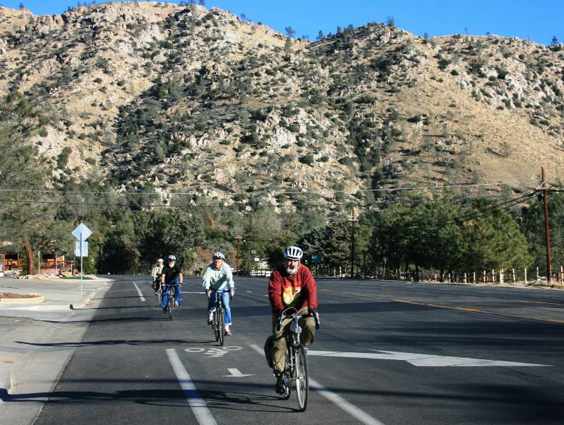
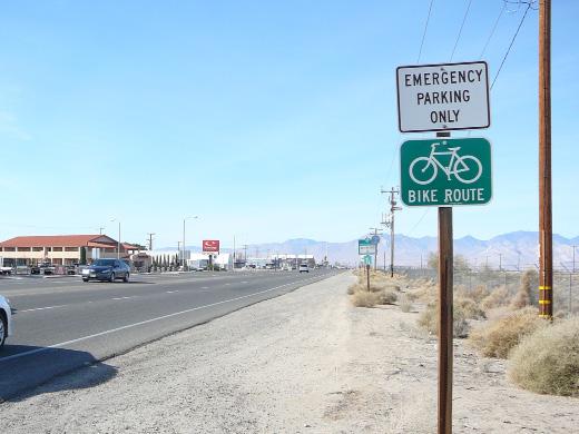
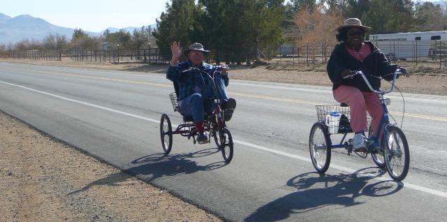
51
Off-road Trails. Guidance
 Off-road Trails Off-road trails are shared use paths located on an independent alignment that provide two-way travel for people walking, bicycling, and other non-motorized users. Trails specifically along
Active Transportation Facility Glossary
 Active Transportation Facility Glossary This document defines different active transportation facilities and suggests appropriate corridor types. Click on a facility type to jump to its definition. Bike
On Road Bikeways Part 1: Bicycle Lane Design
 On Road Bikeways Part 1: Bicycle Lane Design Presentation by: Nick Jackson Bill Schultheiss, P.E. September 04, 2012 FOLLOW THE CONVERSATION ON TWITTER Toole Design Group is live tweeting this webinar
March 2008 FINAL DRAFT. Supplemental Bikeway Design Guidelines
 March 2008 FINAL DRAFT Supplemental Bikeway Design Guidelines Prepared for: Marin County Department of Public Works Marin County Unincorporated Area Bicycle and Pedestrian Master Plan Prepared by: Alta
On-Street Bicycle Facilities
 On-Street Bicycle Facilities A. General 12B-3 Design Manual Chapter 12 - Sidewalks and Bicycle Facilities 12B - Bicycle Facilities Cyclists have similar access and mobility needs as other transportation
REGIONAL BICYCLE AND PEDESTRIAN DESIGN GUIDELINES
 REGIONAL BICYCLE AND PEDESTRIAN DESIGN GUIDELINES November 16, 2011 Deb Humphreys North Central Texas Council of Governments Bicycle and Pedestrian Advisory Committee Snapshot of the Guide 1. Introduction
Appendix T CCMP TRAIL TRAFFIC & TRANSPORTATION DESIGN STANDARD
 Appendix T CCMP 3.3.4 TRAIL TRAFFIC & TRANSPORTATION DESIGN STANDARD 3.3.4 Trail Traffic and Transportation Design Multi-use trails have certain design standards, which vary depending on the agency that
Appendix 3 Roadway and Bike/Ped Design Standards
 Appendix 3 Roadway and Bike/Ped Design Standards OTO Transportation Plan 2040 4/20/2017 Page A3-1 Adopted Standards The adopted OTO Design Standards and Major Thoroughfare Plan are contained herein.
Bowman-Melton Associates, Inc. june 2011
 2011 dallas bike plan ADDENDUM Bowman-Melton Associates, Inc. Complete Streets Initiative Design and policy guidance june 2011 2 2011 Dallas Bike Plan Complete Streets Initiative Design and Policy Guidance
APPENDIX A: Complete Streets Checklist DRAFT NOVEMBER 2016
 APPENDIX A: Complete Streets Checklist DRAFT NOVEMBER 2016 Complete Streets Checklist MetroPlan Orlando s Complete Streets Checklist is an internal planning tool for staff to further implementation of
General Design Factors
 Chapter 3: 3-1.0 Introduction General Design Factors Mn/DOT s goals include encouraging and accommodating safe bicycling. From a design perspective, these goals are achieved by first having an understanding
Chapter 2: Standards for Access, Non-Motorized, and Transit
 Standards for Access, Non-Motorized, and Transit Chapter 2: Standards for Access, Non-Motorized, and Transit The Washtenaw County Access Management Plan was developed based on the analysis of existing
Cycle Track Design Best Practices Cycle Track Sections
 Design Best Practices Sections It is along street segments where the separation and protection methods of cycle tracks offer more comfort than conventional bicycle lanes, and are more attractive to a wide
Chapter 3 DESIGN SPECIFICATIONS
 Brampton PathWays Planning and Design Guidelines 27 Chapter 3 DESIGN SPECIFICATIONS 3.1 CLASS 1 MULTI-USE PATH Off-road multi-use trails are the backbone of the Brampton PathWays Network. They are typically
Albuquerque Bikeways and Trails Master Plan Design Guidelines
 The City of Albuquerque has been working to implement on- and off-street projects to encourage walking and cycling, improve safety and accessibility, and enhance the quality of the walkway and bikeway
CHAPTER 1 STANDARD PRACTICES
 CHAPTER 1 STANDARD PRACTICES OBJECTIVES 1) Functions and Limitations 2) Standardization of Application 3) Materials 4) Colors 5) Widths and Patterns of Longitudinal Pavement Marking Lines 6) General Principles
Designing On Road Bikeways
 Module B Learning Outcomes: Describe features of on road bikeways Select design criteria for on road bikeways in various contexts Bicycle Characteristics Height Handlebar 36 44 in Eye 60 in Operating 100
Broad Street Bicycle Boulevard Design Guidelines
 Broad Street Bicycle Boulevard Design Guidelines Building from the strategies introduced in the 2013 Bicycle Transportation Plan and community input received thus far, City Transportation Staff have identified
Accommodating Pedestrians in the Work Zone
 Accommodating Pedestrians in the Work Zone Guidance for Section C Plan Preparers Some impacts cannot be avoided and those impacts apply to residents, businesses, motorists, and pedestrians alike. However,
MEMORANDUM. Date: 9/13/2016. Citywide Crosswalk Policy
 MEMORANDUM Date: 9/13/2016 Re: Citywide Crosswalk Policy Foreword Through the s Circulation Element and Complete Streets Policy, it is the City s goal to promote walking trips and provide safe facilities
Bicycle Boulevards and Neighborhood Greenways
 Bicycle Boulevards and Neighborhood Greenways Traffic Safety is Improving for Everyone 90 80 70 60 50 40 30 20 10 0 PORTLAND: TOTAL TRAFFIC FATALITIES 1986-2008 1986 1987 1988 1989 1990 1991 1992 1993
Chapter 4 On-Road Bikeways
 Chapter 4: 4-1.0 Introduction On-Road Bikeways This chapter provides guidelines to help select and design safe on-road bikeways. On-road bikeways include bicycle lanes, shared lanes, shoulders, and wide
ADA on Construction. Guidance for Section C Plan Preparers
 ADA on Construction Guidance for Section C Plan Preparers Some impacts cannot be avoided and those impacts apply to residents, businesses, motorists, and pedestrians alike. However, good planning can minimize
Off-Road Facilities Part 1: Shared Use Path Design
 Off-Road Facilities Part 1: Shared Use Path Design Presentation by: Eric Mongelli, P.E. Tom Huber October 9, 2012 FOLLOW THE CONVERSATION ON TWITTER Toole Design Group is live tweeting this webinar @tooledesign
Cheyenne On-Street Bicycle Plan and Greenway Plan Update, Volume II
 Cheyenne On-Street Bicycle Plan and Greenway Plan Update, Volume II Design Guidelines and Policy Handbook June 2012 PREPARED BY: Alta Planning + Design In collaboration wtih Environmental Planning Group
OBJECTIVE: Improve safety by designing all bicycle facilities to the latest AASHTO bicycle guidelines and 2009 MUTCD Standards.
 DESIGN AND APPLICATION OF GUIDELINES AND STANDARDS The Citizen Advisory and Technical Advisory Committees identified improving safety by providing consistent bicycle facilities throughout the region as
This page intentionally left blank.
 Appendix F. Design Guidelines County of Los Angeles Bicycle Master Plan This page intentionally left blank. F-2 Alta Planning + Design F Design Guidelines The County of Los Angeles works to implement on-and
A. Appendix A Design Guidelines
 City of San Mateo Bicycle Master Plan A. Appendix A Design Guidelines This appendix presents an overview of bicycle facility designs, based on appropriate California Manual of Uniform Traffic Control Devices
City of Roseville Section 13 Design Standards. _Bikeways January 2016 SECTION 13 BIKEWAYS
 SECTION 13 BIKEWAYS 13-1 GENERAL The City of Roseville bikeway standards are designed to insure that transportation and recreational bikeways are constructed in a manner that would provide a safe and comfortable
INDOT Complete Streets Guideline & Policy
 INDOT Complete Streets Guideline & Policy INTRODUCTION The Complete Streets guidelines build upon multiple efforts and promote a multimodal transportation system that is integrated and sustains land use
Section 9A.07 Meaning of Standard, Guidance, Option, and Support
 2012 Edition Page 895 PART 9. TRAFFIC CONTROLS FOR BICYCLE FACILITIES CHAPTER 9A. GENERAL Section 9A.01 Requirements for Bicyclist Traffic Control Devices 01 General information and definitions concerning
4. TRAIL DESIGN GUIDELINES
 Trail Design Guidelines 4. TRAIL DESIGN GUIDELINES This chapter provides specific design guidelines for the Humboldt Bay Trail that are consistent with the guidelines currently observed in California and
10.0 CURB EXTENSIONS GUIDELINE
 10.0 CURB EXTENSIONS GUIDELINE Road Engineering Design Guidelines Version 1.0 March 2017 City of Toronto, Transportation Services City of Toronto Page 0 Background In early 2014, Transportation Services
CURBSIDE ACTIVITY DESIGN
 5 CURBSIDE ACTIVITY DESIGN This chapter provides design guidance for separated bike lanes adjacent to curbside activities including parking, loading and bus stops. Typical configurations are presented
Memorandum. Exhibit 60 SSDP To: Jenny Bailey, Senior Planner. From: Bill Schultheiss, P.E. (WA. P.E. #46108) Date: June 20, 2017
 Date: June 20, 2017") Memorandum To: Jenny Bailey, Senior Planner From: Bill Schultheiss, P.E. (WA. P.E. #46108) Date: June 20, 2017 Re: East Lake Sammamish Trail, Segment 2B Review King County has asked Toole Design Group
Memorandum To: Jenny Bailey, Senior Planner From: Bill Schultheiss, P.E. (WA. P.E. #46108) Date: June 20, 2017 Re: East Lake Sammamish Trail, Segment 2B Review King County has asked Toole Design Group
City of Vallejo Traffic Calming Toolbox
 City of Vallejo Traffic Calming Toolbox June 1, 2013 Final Table of Contents Introduction... 1 Non-Physical Devices... 3 High-Visibility Crosswalk... 3 In Pavement Lighted Crosswalk... 4 Rapid Flashing
2012 by the American Association of State Highway and Transportation Officials. All rights reserved. Duplication is a violation of applicable law.
 Table of Contents Chapter 1: Introduction... 1-1 1.1 Design Imperative... 1-1 1.2 Purpose... 1-1 1.3 Scope... 1-2 1.4 Definitions... 1-2 Chapter 2: Bicycle Planning... 2-1 2.1 Background... 2-1 2.2 Why
CHAPTER 16 PEDESTRIAN FACILITIES DESIGN AND TECHNICAL CRITERIA TABLE OF CONTENTS
 CHAPTER 16 PEDESTRIAN FACILITIES DESIGN AND TECHNICAL CRITERIA TABLE OF CONTENTS Section Title Page 16.1 General... 16-1 16.1.1 AASHTO Reference... 16-1 16.1.2 ADA Requirements... 16-1 16.2 Sidewalks...
2.0 LANE WIDTHS GUIDELINE
 2.0 LANE WIDTHS GUIDELINE Road Engineering Design Guidelines Version 2.0.1 May 2018 City of Toronto, Transportation Services City of Toronto Page 0 Background In early 2014, Transportation Services initiated
Design Overview. Section 4 Standard Plans for Design. Pedestrian Access Routes. Pedestrian Access Routes. Overview. Cross Slope
 Design Overview Section 4 Standard Plans for Design Fall, 2017 Ann Johnson, PE Services Brady Rutman, SRF Consulting Group Overview Design Basics Recommendations: The Zone System Driveway Crossings Pedestrian
Shared Use Path Design
 12B-2 Design Manual Chapter 12 - Sidewalks and Bicycle Facilities 12B - Bicycle Facilities Shared Use Path Design A. Accessible Shared Use Path Design 1. General: Applicable portions from the following
The 2012 AASHTO Bike Guide: An Overview
 The 2012 AASHTO Bike Guide: An Overview Presentation by: Jennifer Toole, AICP, ASLA Peter Lagerwey August 10, 2012 {Enter Module Name on Master Slide} WEBINAR #1: OVERVIEW OF 2012 AASHTO BIKE GUIDE Today
Appendices. Appendix A: Design Guidelines
 Appendix A: Design Guidelines This appendix is intended to assist in the selection and design of bicycle facilities. The following pages pull together best practices by facility type from public agencies
Toole Design Group is live tweeting this webinar
 On Road Bikeways Part I1: Non-Bike Lane Design Presentation by: Bill Schultheiss, P.E. Tina Fink, P.E. September18, 2012 FOLLOW THE CONVERSATION ON TWITTER Toole Design Group is live tweeting this webinar
DRAFT. Scholls Ferry Road Conceptual Design Plan Technical Memorandum Multi-Modal Examples. Multnomah County 1600 SE 190th Avenue Portland, OR 97233
 Technical Memorandum Multi-Modal Examples Prepared for 1600 SE 190th Avenue Portland, OR 97233 December 2008 CITATION This project is partially funded by a grant from the Transportation and Growth Management
Appendix A: Crosswalk Policy
 Appendix A: Crosswalk Policy Appendix A: Crosswalk Policy Introduction This citywide Crosswalk Policy is aimed at improving pedestrian safety and enhancing pedestrian mobility by providing a framework
Who is Toole Design Group?
 2018 AASHTO Bike Guide Status Update NCHRP 15 60 Amalia Leighton Cody, PE, AICP & Kenneth Loen, PE Washington APWA October 4, 2018 Who is Toole Design Group? TDG is a full service engineering, planning
INDEX. Geometric Design Guide for Canadian Roads INDEX
 Acceleration lane, see Lanes, Acceleration Access, 8.1 Access Management and Functional Classification 8.2 Access Management by Design Classification 8.3 Access Configuration 8.4 Building Set-Back Guidelines
NJDOT Complete Streets Checklist
 Background The New Jersey Department of Transportation s Complete Streets Policy promotes a comprehensive, integrated, connected multi-modal network by providing connections to bicycling and walking trip
G AT E WAY PLAN. Community BRIEFING KIT GATEWAY BIKE
 G AT E WAY PLAN GATEWAY BIKE Community BRIEFING KIT PLAN August 2016 TABLE OF CONTENTS INTRODUCTION... 1 THE BENEFITS OF A BIKEABLE COMMUNITY... 2 ECONOMY...2 SAFETY...3 HEALTH...3 HOUSEHOLD SPENDING...3
Planning Guidance in the 2012 AASHTO Bike Guide
 Planning Guidance in the 2012 AASHTO Bike Guide Presentation by: RJ Eldridge Peter Lagerwey August 22, 2012 WEBINAR 2: PLANNING GUIDANCE IN THE 2012 AASHTO BIKE GUIDE Today s Webinar Significant Updates
2018 AASHTO BIKE GUIDE
 2018 AASHTO BIKE GUIDE Your presenter Rob Burchfield, PE NW Regional Engineering Director 35 years of experience in traffic engineering and bicycle facility design Toole Design Group Toole Design Group
ROUNDABOUTS/TRAFFIC CIRCLES
 GENERAL 1. Description This standard identifies minimum requirements that shall be met for Roundabouts and Neighborhood Traffic Circles in the design and construction of elements for Arlington County Horizontal
Toronto Complete Streets Guidelines
 88 90 5.1 Cycling Design Principles 92 5.2 Context-sensitive Cycling Facilities 96 5.3 Key Cycling Elements Cycling infrastructure provides choice in how people are able to move around the city. Cyclists
A Insert design-related public comment here.
 Design Guidelines A Insert design-related public comment here. - Public Comment, 2016 This regional plan focuses on connecting regional nodes, such as Wilmington, NC (Gary Shell Cross-City Trail shown
700 Multi-Modal Considerations
 700 Multi-Modal Considerations Table of Contents 701 Railroads... 7-1 701.1 Background... 7-1 701.2 Crossing At-Grade... 7-1 701.2.1 General... 7-1 701.2.2 Railroad Parallel to Highway... 7-1 701.3 Lateral
FHWA Bikeway Selection Guide
 FHWA Bikeway Selection Guide Tamara Redmon Federal Highway Administration Bill Schultheiss Toole Design Lauren Blackburn VHB March 26, 2019 PBIC Webinar pedbikeinfo.org @pedbikeinfo Housekeeping Problems
2018 AASHTO BIKE GUIDE
 2018 AASHTO BIKE GUIDE Your presenters Jessica Fields, PE Denver Office Director Sagar Onta, PE, PTOE Denver Engineering Director 35 years of combined experience street design, transportation planning,
MAG Town of Cave Creek Bike Study Task 6 Executive Summary and Regional Significance Report
 Page 1 MAG Town of Cave Creek Bike Study Task 6 Executive Summary and Regional Significance Report August 1, 2012 MAG Project #481 Page 2 Task 6 Executive Summary and Regional Significance Report Introduction
Access Location, Spacing, Turn Lanes, and Medians
 Design Manual Chapter 5 - Roadway Design 5L - Access Management 5L-3 Access Location, Spacing, Turn Lanes, and Medians This section addresses access location, spacing, turn lane and median needs, including
TRAFFIC CALMING GUIDE FOR TORONTO CITY OF TORONTO TRANSPORTATION SERVICES DIVISION
 TRAFFIC CALMING GUIDE FOR TORONTO CITY OF TORONTO TRANSPORTATION SERVICES DIVISION CITY OF TORONTO TRANSPORTATION SERVICES DIVISION 2016 TRAFFIC CALMING GUIDE FOR TORONTO TABLE OF CONTENTS Introduction
Agenda. Overview PRINCE GEORGE S PLAZA METRO AREA PEDESTRIAN PLAN
 PRINCE GEORGE S PLAZA METRO AREA PEDESTRIAN PLAN May 28, 2008 Agenda Welcome and introductions Project overview and issue identification Planning context and strengths Design challenges and initial recommendations
Coquitlam Cross-town Bike Route Improving Bicycle Facilities in a Mature Suburban Environment
 Coquitlam Cross-town Bike Route Improving Bicycle Facilities in a Mature Suburban Environment Sarah Rocchi, Vice-President, Projects, Opus International Consultants (Main Presenter) Catherine Mohoruk,
Figure 3B-1. Examples of Two-Lane, Two-Way Marking Applications
 Figure 3B-1. Examples of Two-Lane, Two-Way Marking Applications A - Typical two-lane, two-way marking with passing permitted in both directions B - Typical two-lane, two-way marking with no-passing zones
Appendix C. TRAFFIC CALMING PROGRAM TOOLBOX
 Appendix C. TRAFFIC CALMING PROGRAM TOOLBOX PHASE I...2 Do Not Enter Sign...3 One-Way Sign...4 Turn Prohibition...5 Pavement Markings...6 Speed Monitoring Trailer...7 Neighborhood Speed Watch...8 Police
DRAFT Montgomery County Bicycle Master Plan Design Toolkit
 DRAFT Montgomery County Bicycle Master Plan Design Toolkit Fall 2016 Sidepaths Sidepaths are shared use paths located parallel to and within the road right-of-way providing twoway travel for walking, bicycling,
5. RUNNINGWAY GUIDELINES
 5. RUNNINGWAY GUIDELINES These guidelines should be considered collectively when making runningway decisions. A runningway is the linear component of the transit system that forms the right-of-way reserved
DESIGN GUIDANCE 1. INTRODUCTION 2. PRIORITIZED STATEWIDE BICYCLE NETWORK
 DESIGN GUIDANCE 1 1. INTRODUCTION This document presents context sensitive guidance for the selection and maintenance of bikeway infrastructure along roadway facilities owned and maintained by NMDOT. The
Critique of the 2012 AASHTO Guide for the Development of Bicycle Facilities Bicycle Lane width specifications. Wayne Pein
 Critique of the 2012 AASHTO Guide for the Development of Bicycle Facilities Bicycle Lane width specifications Wayne Pein wpein@nc.rr.com February 2014 AASHTO Guidelines In describing the bicycle Design
Complete Streets Design Considerations. Second Street Corridor Complete Streets Workshop and Assessment Manchester, NH April 26, 2013
 Complete Streets Design Considerations Second Street Corridor Complete Streets Workshop and Assessment Manchester, NH April 26, 2013 2 nd Street Existing Information Average Annual Daily Traffic Volumes
Duwamish Way-finding and CTR Report
 V. North Tukwila When the North Tukwila Manufacturing and Industrial Center was designated in 1992 as part of the region s land use and transportation plan, the plan called for the area to set a light-rail
(This page left intentionally blank)
") (This page left intentionally blank) 2011 Edition- Revision 2 Page 813 CHAPTER 9A. GENERAL Section 9A.01 Requirements for Bicyclist Traffic Control Devices 01 General information and definitions concerning
(This page left intentionally blank) 2011 Edition- Revision 2 Page 813 CHAPTER 9A. GENERAL Section 9A.01 Requirements for Bicyclist Traffic Control Devices 01 General information and definitions concerning
City of Albert Lea Policy and Procedure Manual 4.10 ALBERT LEA CROSSWALK POLICY
 4.10 ALBERT LEA CROSSWALK POLICY PURPOSE: Pedestrian crosswalks are an integral part of our transportation infrastructure. To be effective and promote safety, marked crosswalks must be installed after
Driveway Design Criteria
 Design Manual Chapter 5 - Roadway Design 5L - Access Management 5L-4 Driveway Design Criteria A. General For efficient and safe operations, access drives and minor public street intersections can be improved
Task 4 Wayfinding Elements, Placement and Technical Guidance 4.1 Wayfinding Elements
 1836 Blake Street Denver, CO 80202 720.524.7831 ww.altaplanning.com MEMO 3 Task 4 Wayfinding Elements, Placement and Technical Guidance 4.1 Wayfinding Elements Based on field reconnaissance, best practices
C/CAG. Sunnybrae Elementary School Walking and Bicycling Audit. San Mateo-Foster City School District JUNE 2013
 Sunnybrae Elementary School Walking and Bicycling Audit JUNE 2013 San Mateo-Foster City School District C/CAG City/County Association of Governments of San Mateo County SUNNYBRAE ELEMENTARY SCHOOL WALKING
A Traffic Operations Method for Assessing Automobile and Bicycle Shared Roadways
 A Traffic Operations Method for Assessing Automobile and Bicycle Shared Roadways A Thesis Proposal By James A. Robertson Submitted to the Office of Graduate Studies Texas A&M University in partial fulfillment
Steps to Conducting a Complete Streets Assessment
 Steps to Conducting a Complete Streets Assessment Familiarize yourself with Complete Streets Read through the Complete Streets Assessment Guidelines. This will give you an idea of what Complete Streets
Multimodal Through Corridors and Placemaking Corridors
 68 Multimodal Through Corridors and Placemaking Corridors Corridors have different functions in a region. Some corridors are used to get smoothly and rapidly through a region or to get quickly to major
Appendix C. City of Fort Collins Recommended Bicycle Design Guidelines. Appendix C: Recommended Bicycle Design Guidelines 1
 Appendix C City of Fort Collins Recommended Bicycle Design Guidelines Appendix C: Recommended Bicycle Design Guidelines 1 This appendix provides general design considerations for implementation of bicycle
Appendix C. Bicycle Route Signage
 Appendix C Bicycle Route Signage This page intentionally left blank. APPENDIX C - BICYCLE ROUTE AND WAYFINDING SIGNAGE Bicycle route signs are wayfinding signs that guide bicyclists along preferred, designated
Appendix F: Wayfinding Protocol and Best Practices
 Appendix F: Wayfinding Protocol and Best Practices Table of Contents Introduction... 259 Current Practice... 259 Policy and Regulatory Framework... 260 Best Practices... 262 Chicago, IL... 262 Seattle,
Cyclists and Bikeways: What s your match? A guide to bikeway options for a variety of cyclists
 Cyclists and Bikeways: What s your match? guide to bikeway options for a variety of cyclists The workshop and this resource were made possible by funding from the Province of Ontario via the Ministry of
WYDOT DESIGN GUIDES. Guide for. Non-NHS State Highways
 WYDOT DESIGN GUIDES Guide for Non-NHS State Highways 2014 GUIDE FOR Non-NATIONAL HIGHWAY SYSTEM (Non-NHS) STATE HIGHWAYS PRESERVATION REHABILITATION RECONSTRUCTION INTRODUCTION This Guide is directed to
South Carolina Department of Transportation. Engineering Directive
 South Carolina Department of Transportation Engineering Directive Directive Number: ED-22 Effective: December 16, 2009 Subject: References: Purpose: This Directive Applies to: Considerations for Bicycle
Color your stress away
 Color your stress away Learn about the Bicycle Master Plan s comfortable, low-stress bicycling network in Montgomery County. Unwind as you color the bicycling scenes. Check out montgomeryplanning.org/bikeplan
Proposed. City of Grand Junction Complete Streets Policy. Exhibit 10
 Proposed City of Grand Junction Complete Streets Policy Exhibit 10 1 City of Grand Junction Complete Streets Policy Vision: The Complete Streets Vision is to develop a safe, efficient, and reliable travel
Chapter 4 Engineering 4.12 Sample Cross-Sections
 The following text was originally published as part of MORPC s Complete Streets checklist, along with our adopted policy. It is included here both for completeness and for visual updates. Three dimensional
Physical Implications of Complete Streets Policies
 Presentation Overview Physical Implications of Complete Norm Cox, ASLA, LLA Landscape Architect Ann Arbor, Michigan, 10:45 to Noon What Are Complete Streets? What Matters to Bicyclists and Pedestrians
MINNEAPOLIS PARK & RECREATION BOARD DRAFT TRAIL DESIGN STANDARDS FOR: SIGNS AND PAVEMENT MARKINGS
 MINNEAPOLIS PARK & RECREATION BOARD DRAFT TRAIL DESIGN STANDARDS FOR: SIGNS AND PAVEMENT MARKINGS October 14, 2014 CHANGE LOG Additions and changes to this document should be summarized on this page and
4.1 CONTEXT. The existing terrain and sight conditions will affect available sight lines and approach speeds of bicyclists and motorists.
 4 INTERSECTION DESIGN This chapter provides key principles that should be used to develop and evaluate design approaches and treatments that will result in intersections that support all ages and abilities
ACTIVE TRANSPORTATION
 ACTIVE TRANSPORTATION Mobility 2040 Supported Goals Improve the availability of transportation options for people and goods. Support travel efficiency measures and system enhancements targeted at congestion
WYDOT DESIGN GUIDES. Guide for. NHS Arterial (Non-Interstate)
") WYDOT DESIGN GUIDES Guide for NHS Arterial (Non-Interstate) 2014 GUIDE FOR NATIONAL HIGHWAY SYSTEM (NHS) HIGHWAYS (NHS ARTERIALS, Non-Interstate) PRESERVATION REHABILITATION RECONSTRUCTION INTRODUCTION
WYDOT DESIGN GUIDES Guide for NHS Arterial (Non-Interstate) 2014 GUIDE FOR NATIONAL HIGHWAY SYSTEM (NHS) HIGHWAYS (NHS ARTERIALS, Non-Interstate) PRESERVATION REHABILITATION RECONSTRUCTION INTRODUCTION
Geometric Design Tables
 Design Manual Chapter 5 - Roadway Design 5C - Geometric Design Criteria 5C-1 Geometric Design Tables A. General The following sections present two sets of design criteria tables - Preferred Roadway Elements
TOWN OF PORTLAND, CONNECTICUT COMPLETE STREETS POLICY
 TOWN OF PORTLAND, CONNECTICUT COMPLETE STREETS POLICY I. VISION, GOALS & PRINCIPLES VISION To improve the streets of Portland making them safer and more accessible for all users including pedestrians,
Appendix A. Knoxville TPO Greenway Signage Guidelines. Appendix A: Knoxville TPO Greenway Signage Guidelines Knox to Oak Ridge Greenway Master Plan
 Appendix A Knoxville TPO Greenway Signage Guidelines 75 Overview: Adequate signing and marking are essential on shared-use paths, especially to alert bicyclists to potential conflicts and to convey regulatory
Small Town & Rural Multimodal Networks
 Small Town & Rural Multimodal Networks Fred Young, PLA Andrea Clinkscales, AICP, PMP Alta Planning + Design Funding Partners Project Team Existing Design Guidance AASHTO Flexibility Guide 2004 AASHTO Bike
This Chapter sets forth the minimum design, technical criteria and specifications to be used in the preparation of all roadway plans.
 4.1 GENERAL This Chapter sets forth the minimum design, technical criteria and specifications to be used in the preparation of all roadway plans. These Roadway Standards are for new construction and modification
Chapter 5: Crossing the Street
 Chapter 5: Crossing the Street Whether walking or bicycling, a student s journey to school will more than likely require crossing one or more streets. Per the Safe Routes to School Guide, maintained by
What Is a Complete Street?
 Session 5 Charleen Zimmer, AICP, Zan Associates May 5-7, 2010 What Is a Complete Street? May 2010 5-1 Not a Complete Street More of a Complete Street May 2010 5-2 Benefits of Complete Streets Safety for