NZ Transport Agency Speed management. guide. 2 P a g e
|
|
|
- Rudolph Murphy
- 6 years ago
- Views:
Transcription

1
2 NZ Transport Agency Speed management m guide P a g e
3 NZ Transport Agency Speed management m guide 2015 Table of Contents TOOLBOX... 4 How to Implement Treatments and Activities... 4 Treatment Philosophy 4 Education and Communication 5 Key treatment philosophies 6 Hierarchy of measures 7 Treatment Philosophy based on risk, ONRC and key issues 8 Treatment Philosophy based on ONRC 9 Treatment Philosophy based on key crash type 9 Toolbox Items...11 Roads and Roadsides 14 Safe Vehicles 68 Safe Road Use 69 APPENDICES RULE REQUIREMENTS, TRAFFIC CONTROL DEVICES AND TECHNICAL SPECIFICATIONS...72 Speed Management General Rule Requirements...72 Legal framework and implications 72 Traffic Control Devices (TCD) Definitions and Principles 73 Roles and Responsibilities in setting speed limits 74 Consultation, decision-making procedures, registration and recording of speed limits 75 Speed limits - signs and markings 77 Traffic Calming Devices Signs and Markings 93 Speed Indicator Devices...98 Purpose 98 Background 98 Operating Policy 98 Operational Procedures 98 SID Display 99 Variable Speed Limit Signs Purpose 100 Warrant 101 Speed Thresholds Application and threshold treatments 107 Rural- urban thresholds 108 Design considerations 109 Urban-urban thresholds 117 Rural -rural threshold 117 Design, location and siting of Speed Humps Permanent Road Humps 119 Rural Intersection Advanced Warning Signs (RIAWS) Background 123 Outcomes from the RIAWS trials 123 Use of RIAWS following the trial 124 Required approval 124 Site Selection 124 Important considerations 125 Safer speed area, shared zones Safer Speed Areas 126 Shared Space 126 Typical Arrangements for LATM devices P a g e
4 NZ Transport Agency Speed management m guide 2015 Toolbox HOW TO IMPLEMENT TREATMENTS TMENTS AND ACTIVITIES The key treatment philosophies include engineering and infrastructure improvements, enforcement methods, education and vehicle technology. The type and scale of treatment used is based on: Level of risk ONRC Key crash types and issues This section provides rules, standards and guidance on the use and application of traffic control devices for speed management. However, practitioners should always apply sound engineering judgement in using and installing traffic signs and markings to ensure they will be effective at any particular site. For instance, the road geometry at a site may require the sign to be installed at a better location than specified in this document. In such cases, engineering judgement should be used and any departures from recommended practice documented. It is important to consider a consistent approach to the corridor and sites with a route. To be effective, speed management measures need to combine a number of different treatments. Treatment Philosophy Effective speed management treatments are likely to be as a result of a combination of measures. It is important that infrastructure changes, enforcement and education strategies are used together. When determining the scale and type of treatment consideration should be given to risk, road function and type of crashes. Engineering and Infrastructure Engineering and infrastructure measures are effective treatments in helping manage speeds and severity outcomes. The type and scale of these measures should largely depend on the road function, safety, design and use. For example, the types of intersections that would suit a four-lane high volume road with a 110 km/h posted speed limit are those that are grade separated. As these roads primary function is the effective movement of traffic then it is not ideal to use intersection forms and controls, such as traffic signals or roundabouts that would significantly interrupt the flow. Where the function of the road is lower volume and access, more appropriate measures include traffic calming techniques such as speed humps, chicanes and road narrowing, along with redefining spaces as shared zones and providing additional measures that cater for active modes. A list of engineering and infrastructure measures for road function, risk and key issues are provided in Toolbox Table 3. Enforcement In developing a Speed Management Plan, RCAs need to involve Police throughout the process as they are responsible for enforcement. Enforcement supports the safe system goal of alert and compliant road users. When complemented with sound risk analysis it will ensure better compliance with speed limits and thereby reduce deaths 4 P a g e
5 NZ Transport Agency Speed management m guide 2015 and serious injuries. Enforcement is an effective speed management intervention in its own right as well as supporting other interventions such as increased or reduced posted speed limits. Speed enforcement is based on the assumption that a driver knows the limit and rationally chooses the travel speed.1 In practice, road and vehicle design can sometimes encourage higher speeds. Compliance is higher when the speed limit is perceived to be consistent with that road s function, design, safety risk and use and is, therefore, judged to be credible2. While compliance can be improved through better road and roadside design and in-vehicle reminder systems, enforcement is also an important cue to increase driver care in monitoring their speed, and plays an important role for those who choose to disregard other cues. The aim of enforcement is to deter the driver or rider from deliberately driving too quickly by increasing the perception that there is: a high likelihood of being caught a high likelihood of receiving a penalty the penalty is meaningful. For enforcement to be an effective deterrent the road user must believe that all three apply. For enforcement to reduce death and serious injury, the enforcement must reduce speed where speed is contributing to road trauma. The Safer Journeys Safer Speeds Programme seeks to bring New Zealand into line with international best practice in enforcement. They will help to deter excess speed by increasing the perception that a penalty for speeding is likely, and ensuring the penalties are more meaningful. Two actions currently being investigated would enable better and more consistent enforcement. They would be particularly targeted at reducing crashes where speed in excess of the limits causes the crash or the level of trauma. They would also have the supporting benefit of improving homogeneity in speed (reducing variation from the mean), which is correlated with better safety and economic outcomes including better throughput of vehicles, better network efficiency and better travel time for the majority of road users. These two proposed actions are: 1. Encourage and support Police to reduce the current speed enforcement threshold to more consistently reflect the speed limits and support the one network framework, to reduce the proportion of road users who exceed the speed limits, prevent low end speeding and improve traffic flow and throughput. 2. Rebalance the penalty regime to provide for demerit points on safety camera offences, to ensure fairer penalties, increase deterrence, and ensure penalties are more reflective of road safety risk. Subject to official approval, both of these changes would be implemented at the same time as they reinforce each other, the communication messages are very similar, and there would be an opportunity for a consolidated conversation with the public about why enforcement saves lives and serious injury. Implementing them at the same time would be expected to reduce the overall levels of infringement notices issued over the life of the programme. They will also be supported by better targeting of enforcement and increased use of safety cameras, including both speed cameras and red light cameras, and other camera system such as point-to-point, which are already occurring. These actions aim to increase the likelihood of being caught speeding, especially in high risk areas. The Police in association with other road safety partners are currently refining existing site-selection criteria for safety cameras and deployment of officer-based enforcement. Education and Communication The types and methods of information the public, school children, policy makers and safe system designers receive and are part of the decision making process is vitally important in the successfulness of any speed management 1 Fildes and Lee, The Speed Review: Road environment, behaviour, speed limits, enforcement and crashes. Monash University Accident Research Centre. 2 SWOV fact sheet on credible speed limits 5 P a g e
6 NZ Transport Agency Speed management m guide 2015 campaign. The OECD, 2008, provides a number of key points in helping to inform, influencing and involve the public and key stakeholders with speed management. Specifically to: Assess community attitudes to speed management Advise and educate drivers and other roads users about speed management action and the change in behaviour expected of them Motivate compliance with speed limits and safe speeds Encourage public support for actions to address the speed problem. OCED, 2008 provides further guidance eon regulating and enforcing speed, public education, community based programmes, working with the media, planning a campaign roll-out, carrying out the camping, undertaking pilot projects, Partnerships are important in helping deliver effective speed management programmes and the Transport Agency works closely with local and regional councils, as investment partners, to help deliver good safety outcomes in local communities The NZ Transport Agency will be working to help people understand what travelling at safe speeds means through effective use of safe system tools such as network and speed management interventions, road and vehicle technologies, enforcement, promotion, incentives and cultural change. Safe system demonstration areas, which include safe speed management, will be one of the tools used. Changing the conversation is a key part of the Transport Agency s approach. An upcoming Transport Agency campaign will look to inform and shift the debate about speeding to help drivers make informed and conscious decisions to travel at safe speeds. An initial campaign in late 2012 will begin this process, with a further campaign planned for 2013 and beyond. The aim is to raise awareness of the benefits of travelling at safer speeds, and tackle the myth that speeding just a few kilometres over the limit is not a safety issue. We also need to communicate the strong link between travel speeds and serious trauma, and help people understand the importance of adjusting speed as conditions change. The campaign will help road users make informed and conscious decisions to travel at safe speeds, supported by the subconscious signals they receive from the design, layout and safety features present on the road. The campaign for will target road users through education and advertising campaigns for: high concern areas outlined in Safer Journeys - alcohol and drugs, motorcycles, young drivers, roads and roadsides and speed medium-concern areas as identified in Safer Journeys - high-risk drivers, walking and cycling, vehicles, fatigue, and distraction areas where there is a disproportionate risk for road users in some areas compared to others (e.g., where there is low use of restraints) through our Communities at Risk assessments The road safety promotion investment also allows for opportunities to enhance or promote transport sector activities, including infrastructure improvements, police interventions and regulatory change. The Rightcar website ( which encourages buyers to choose safer, cleaner and more economical cars will continue to be funded via the NLTP. Further information on these campaigns can be found at Key treatment philosophies There are five key treatment philosophies (Toolbox Table 1) that have been developed for high-risk rural roads and high-risk intersections, the principles of which could also be applied (to a greater or lesser extent) to speed management measures. These treatments are largely defined as a result of collective risk, personal risk, Road 6 P a g e
7 NZ Transport Agency Speed management m guide 2015 Protection score, Road Safety Infrastructure Assessment and Traffic Volumes and can be calculated for rural roads and in some part intersections Further information can also be found within the Transport Agency s High risk rural roads guide and High-risk intersection guide. Treatment philosophy Safety maintenance Safety management Safe corridors and intersections Safe system transformation works (Safe system) Site-specific treatments Description Maintaining roads to an appropriate standard in accordance with specified standard criteria. Example measures include maintaining skid resistance to current specified levels to help keep vehicles on the road. Measures aimed at optimising safety levels through maintenance of the existing road network such as skid resistance. Generally, high personal risk roads or sites with low traffic volumes will not warrant significant infrastructure investment. It will therefore be important to consider supplementing safety management on these routes with additional speed management (curve warning signs) education and enforcement measures, and intersection sites with hazard awareness technologies, minor kerb improvements, and pedestrian refuges Infrastructure and speed management measures that improve safety, though to a lesser extent and generally at a lower cost compared to safe system transformation works. Example measures include delineation, speed activated warning signs, seal widening, and audio tactile profiled (ATP) markings. Medium cost intersection improvements such as right turn bays, visibility improvements, signal upgrades, and mass action treatments including passively safe roadside equipment and coloured surfacing to cycleways. Measures that eliminate or significantly reduce the potential for fatal and serious injury crashes. These include infrastructure measures that physically separate road users and/or speed management measures that reduce impact speeds to survivable human tolerance limits. Example infrastructure measures include median barriers, roadside barriers, clear zones, roundabouts, signalised intersections or crossing points, grade separated intersections or cyclist and pedestrian facilities These measures are used where you have crash clusters (black spots) along a route or at just one site. Depending on where the crash cluster is located, and to be consistent with other measures along the route, the types of treatments can be from a range of measures covering safe system transformation works, safer corridors and intersections/accesses, safety management and safety maintenance. Toolbox Table 1: Key treatment Philosophies As these are general treatment philosophies that affect all road users, further consideration needs to be given to providing appropriate treatments for specific issues in terms of speed management. This is explained further in this section. Hierarchy of measures When developing a speed management programme here may be a range of countermeasures to consider, ranging from lower cost treatments, such as temporary signs and markings, to barriers, electronic signs, intersection treatments to grade separated facilities. It is important that the issues are discussed in depth at the start of the project and whether certain treatments may be implemented and monitored for effectiveness in the interim before larger cost measures can be considered and whether if the risk is high that and the speed limit and risk do not match the function of the road that temporary measures including speed limits are implemented until that risk is reduced.. This is important as the larger cost measures can take a considerable amount of time to plan, design and construct. Consideration should also be given to implementing works where other works may already be programmed. For instance, intersection improvements could be completed at the same time as an area-wide treatment to save on costs. 7 P a g e
8 NZ Transport Agency Speed management m guide 2015 Treatment Philosophy based on risk, ONRC and key issues Collective Risk approach Collective risk is a measure of the total number of fatal and serious injury crashes per kilometre (or crash density). These high crash density routes can help determine where the greatest safety gains (best target for $ per kilometre) can be made from investment in infrastructure. While large infrastructure improvements do not fit into the low-cost safety management measures for collective routes, other treatments (such as median treatments that separate oncoming traffic and improved delineation that create more self-explaining roads) would help reduce the number and severity of crashes along these routes. Further information on calculating and treating high collective risk sites are provided within the NZ Transport Agency s high-risk rural roads guide and high-risk intersection guide. Personal Risk approach Personal risk is a measure of risk to each individual using the road being assessed. It is based on fatal and serious injury crashes, and traffic volumes. Sites where there are high personal risks are likely to be in environments with more difficult terrain and where traffic volumes and road standards are often lower. It is recognised that the nature and function of this road does not justify that high-cost infrastructure measures be implemented to reduce fatal and serious crashes. We need to recognise that risk cannot be eliminated through infrastructure improvements alone. We are not going to engineer our way out and other lower cost incremental measures are more feasible where larger cost projects are not. Drivers must share responsibility for a Safe System and take care to minimise their risk until road improvements are made. A risk-aware driver will be better informed and more able to identify situations where they need to modify their behaviour to respond to the conditions. Further information on calculating and treating high personal risk sites and routes can be found within the NZ Transport Agency s high-risk rural roads guide and high-risk intersection guide. The key treatment philosophies regarding speed management treatments are identified in Toolbox Table 2 with the following areas based on Collective and Personal Risk: Site or Route Risk Types of Speed Management Treatment philosophy Specific Treatment High Collective and High Personal Risk Safe System Transformation and efficiency. Investment in high volume roads to at least 3 star level. They need to be safer at higher speed limits ( km/h) Continued Enforcement fixed speed camera s at highrisk sites Grade Separated intersections Median and side barriers Routes Sites High Collective and Low Personal Risk Low Collective and High Personal Risk Low Collective and Low Personal Risk High-risk intersections Out of Context Curves Continued enforcement and Safe System Transformation works (travel efficiency is critical) Speed Management and Low cost measures (less emphasis on efficiency) Continued Enforcement Dependant on the function of the road. Dependant on function of the route Continued Enforcement Grade Separated intersections Median Barriers Speed Limits and treatments matched to road type i.e. local area traffic management in Class 4: Access and Low volume roads Enforcement mobile speed camera s Continued Enforcement Speed Limits that reflect risk Signs and markings Dependant on key issues and function. A higher function road is more likely to need a grade separate facility where as a low volume access road may consider restriction of movements or change of control Realignment or advisory speed signs Toolbox Table 2: Speed Management Treatments based on Risk 8 P a g e
9 NZ Transport Agency Speed management m guide 2015 Treatment Philosophy based on ONRC It is important that the treatment considered not only matches risk but also the function of the road. It is necessary to manage speeds appropriate to its primary use. I. e a high volume road needs to be able to move traffic efficiently and safely and therefore reducing the speed limit along this type of road is not appropriate. It is more appropriate to provide an environment (be it a higher speed one) that provides a safe system environment where there is a low probability of a fatal or serious crash occurring. The following speed management treatments are based on the ONRC: ONRC Classification Types of Treatments Treatment Class 1: High Volume Class 2: National Strategic Regional Strategic Arterial Class 3: Primary Collector Secondary Collector Class 4: Access Low Volume access and all winding/tortuous roads Safe System Transformation and it is critical to maintain or improve efficiency. Therefore it is undesirable to have uninterrupted flows or additional conflict areas. Roads need to be at least a 4 star alignment These road are critical to social and economic wellbeing so largely about the effective movement of traffic and freight. These roads should be at least a 3 star alignment. These types or roads are still about the movement of traffic but less important and have lower volumes, less freight and more active road users These roads are all lower volume rural or urban roads and may cater for a higher percentage of active road users in a mixed use space For urban areas the focus should be on reducing speeds to less than 50km/hr 4 lane, median divided, with protected roadsides grade separated facilities, and justify higher speed limits ( km/h) Consistent passing opportunities ( or arrangements) median divided, with protected roadsides wider shoulders km/hr ( straight/open road/urban motorways) 60-80km/h winding open road) 50-80km/h (Urban) higher speed limits suggested only where there are few intersections and mode separation for active road users. - Road space reallocation Cycle lanes Wider shoulders 60-80Km ( rural) 30-50km/h (urban) Active signs Toolbox Table 3: Speed Management Treatments based on ONRC Speed Humps, Chicanes, road narrowing, road closures, active mode facilities, speed limits less than or equal to 50km/h Advisory speed signs and markings Variable or lower permanent (60-80km) speed limits based on environmental conditions Treatment Philosophy based on key crash type Once you have clarified the risk level it is important to understand the types of crashes that are occurring> i.e. are they a head-on problem, loss of control on curves, at intersections or primarily involve active road users. Toolbox Table 4 shows possible treatments for various crash types, short to medium and long term measures. The level of investment should suit the risk and function of the road. I.e. on higher volume, high collective risk routes where efficiency is paramount a longer term, higher cost measure would be desirable. 9 P a g e
10 NZ Transport Agency Speed management m guide 2015 Key Crash Type or issues Possible Measures Short to medium term Long term Loss of Control Crashes Intersection Crashes Head on Crashes Overtaking Crashes Cyclist Crashes Pedestrian Crashes Travelling above the speed limit or too fast on approach to a hazard Advisory Speeds High skid surfacing and Increased skid resistance Wider shoulders Hazard removal Reduction in approach speeds by signs and visual measures Enforcement Reduction and removal of movements Lower speed limits Enforcement Centreline treatments Marked median treatments ATP markings Improved delineation (signs and markings) Active signs Increased skid resistance/intervention levels (HRRRG) Lower speed limits Improved delineation Enforcement Dedicated facilities Wider shoulder Traffic Calming Safe road use and education Lower speed limits Improved delineation and signs Enforcement Dedicated facilities Traffic Safe road use and education Variable speed zones Improved road marking to provide visual narrowing Improvements to marking and signs at access or intersections Improved, larger and or active signs Increased enforcement (communication with the Police) Frictional or coloured surfacing Realignment Grade Separation Roundabouts Median Divided Median barriers (solid/semiflexible/flexible) (HRRRG) Separated facilities Shared space Separated facilities Shared space Wider shoulders Separated and/or protected road users facilities Change of road function and associated characteristics Local area traffic management/calming in urban areas Toolbox Table 4: Speed Management Treatments based on Key Crash types and issue * the code provided in the bracket (e.g. RR6) denotes the toolbox number within this guide or refers to a toolbox provided in the Transport Agency s High-risk rural roads guide(hrrrg) and/or the High-risk intersection guide(hrig). 10 P a g e
11 NZ Transport Agency Speed management m guide 2015 TOOLBOX ITEMS A number of speed management countermeasures have been identified in this section of which a summary is provided in Toolbox Table 6. In most situations it is important to consider a range of treatments depending on whether it is an urban or rural environment. A detailed description of each treatment is provided in this toolbox and includes the following information provided in Toolbox Table 5. Description Application Describes the countermeasure How the countermeasure can be applied Considerations What considerations are associated with using the countermeasure Speed management effect What is the likely speed management effect e.g. speed reduction, speed homogeneity or allows safe movement at current or higher speed Crash reduction The effectiveness of the countermeasure. Crash reduction percentages are sourced from a variety of references and therefore there are a range of values Other benefits Cost Treatment life What other benefits do you get by using the countermeasures Cost can be site specific (e.g. grade-separated interchange) or cost per kilometre (such as length of median barrier). Costs are sourced from a variety of references and therefore there are a range of values. These should be considered indicative only and do not include maintenance costs Potential cost; $ $50,000 per item or per km (low cost), $$ = $50,000 to $500,000 per item or km (medium cost), $$$ = $500,000+ per item or km (high cost) Describes range of years as deterioration can be site specific. Treatment life is sourced from a variety of references and therefore there are a range of values References and References any sources of information used to describe or guidelines/guidance evaluate the countermeasure. documents Toolbox Table 5: Summary of how each treatment is described and its application 11 P a g e
12 NZ Transport Agency Speed management m guide 2015 Toolbox item Roads and Roadsides Safe System Element Road Safe User Speeds Safe Vehicles Toolbox Number Regulatory Speed limit Signs Advisory Speed Devices Enhanced Signing Traffic Calming Device/LATM Active Road User Facilities Self-explaining explaining roads Road Space Reallocation Intersections Temporary Measures to Reduce Speed Surfacing Static permanent speed limit signs RS1 Variable Speed limit Signs RS2 RS3 Rural Intersection Activated Warning Signs Advisory speed signs AS1 Static curve and speed advisory signs AS2 Speed activated warning Sign - AS3 General Speed Indicator Devices AS4 (Permanent) Speed Indicator Devices AS5 (Temporary) Speed Limit Ahead Sign AS6 Other active Warning Signs AS7 General ES1 Speed Thresholds ES2 Traffic Calming on Arterial roads TC1 Speed Limits Less than 50km/h TC2 General TC3 Main streets TC4 Entry Treatments TC5 Vertical Displacement Devices TC6 Horizontal Displacement Devices TC7 Intersections TC8 Road Closures TC9 One way streets TC10 Mid-block islands TC11 Cycle facilities AR1 Pedestrian facilities AR2 roads Self-explaining roads SE1 Transverse Road Markings SE2 Shared Space Lower Speeds RS1 Road Space Reallocation higher RS2 speeds Lane Narrowing/Centreline RS3 Traffic Control change in priority IN1 Traffic Control change in form IN2 Temporary Signs TM1 Temporary speed Signs TM2 Displacement and Delineation TM3 Surfacing Frictional Surfacing SU1 12 P a g e
13 NZ Transport Agency Speed management m guide 2015 Toolbox item Roads and Roadsides Safe System Element Road Safe User Speeds Safe Vehicles Toolbox Number Highway Related Technology Vehicle s and vehicle technology Education and advertising Coloured Surfacing SU2 Highway Related Technology HT1 ISA, ESC, power to weight ratios, speed limiters NZ Transport Agency Advertising Guide SV1 EA1 The Safe System Education Toolkit EA2 NZ Transport Agency Education EA3 Portal Toolbox Table 6 : Summary of Toolbox measures 13 P a g e
.")
14 Roads and Roadsides Regulatory Speed Limit Signs RS1: Static permanent speed limit signs Description A speed limit sign is a regulatory sign that shows the maximum speed limit that you can travel at under good conditions. There are a range of speed limits and signs that can be used (See Appendix A). A speed limit change takes effect as a result of a legislative process which will specify the location of the change in speed limit. Application The requirement of the use and placement of speed limit signs is found within the Land Transport Rule: Setting of Speed Limits In summary, signs must be installed to instruct road users of the speed restriction: At each point where the restriction changes No more than 20m from its legal position Where the restriction applies to a length of road - At the start; and - At the end; and - At intervals along its length (for non-default speed limits) Where the restriction applies to a zone restriction at: - Each entry point to the zone; and - Intervals within the zone (for non-default speed limits); and - Each exit point from the zone. Considerations Additional information on sign placement, location, distance between signs and associated rules can be found in Appendix A. For sign layout and dimension refer to the Transport Agency s Traffic Specification website: The length of a speed zone needs to be long enough so that compliance is likely; speed limit changes for short lengths are undesirable, where numerous short changes in speed limits can confuse road users. Minimum speed limit lengths are provided in Appendix section See Setting of Speed Limits Rule, 2003 for more information. Speed management effect Crash reduction The location of the signs should be clearly visible and located at locations where the road environment changes thus enhancing the credibility of the speed limit change. In addition the placement of a speed limit sign does not necessarily mean road users will comply with it. Other measures, particularly in lower speed low access road environments may be necessary to achieve lower operating speeds. There are many factors that determine compliance with speed limits. In general speed limits must be safe and appropriate for a road with regard to the function, nature and use of the road, its environment, land use patterns, and whether the road is in an urban traffic area or a rural area. If the posted speed limit matches the function and look of the road compared with an inappropriate speed limit then operating speeds are likely to match that posted speed limit. Where a more appropriate speed limit is introduced it may result in the top end of the speed distribution curve dropping and less crash risk. An associated reduction in crashes is likely to accompany any lower operating speed. Refer to figure 2-3 of the High-risk rural roads guide which shows the relationship between the change of mean speed and casualties on rural roads 14 P a g e
 Setting of Speed Limits Rule, (Agency); NZ Transport Agency s TCD Manual and Traffic Specifications OECD, ECMT (2006). Speed Management. OECD Publishing, Paris, France. www.")
15 Other benefits Cost $ Treatment life References Providing consistent speed environments can result in more efficient movement of traffic and improved trip time reliability 5-10 years (NZ Transport Agency) Setting of Speed Limits Rule, (Agency); NZ Transport Agency s TCD Manual and Traffic Specifications OECD, ECMT (2006). Speed Management. OECD Publishing, Paris, France. Speed.pdf Refer to Toolbox Table 5 for summary for definitions of description, application, considerations, crash reduction, cost, treatment life and references RS2: Variable Speed Limit Signs Description Variable speed limit signs are electronic signs that are typically activated for short periods to manage a particular risk such as during school periods (Appendix Technical Specification for 40km/h school zones), environmental conditions and at intersections (RIAWS Toolbox AS4) or to manage traffic congestion. When activated, variable speed signs reduce the legal speed limit and are therefore enforceable, although pragmatic enforcement is encouraged. Other active signs without speed limits reductions can also be used at high risk times and locations (Toolbox AS7) The speed limit roundel and numerals illuminate when activated with alternate flashing lights to capture driver s attention. Application 40km/h speed limits for school zones are generally reserved for urban areas or where there is an identified pedestrian or cyclist risk in a rural area. The speed environment should first be reduced to a maximum of 80km/h in rural areas (Speed limits of 60km/h have been trialled at schools in rural areas where there is a turning vehicle risk only). The application varies depending on the sign used. In some situations standard traffic control devices and the level of activity outside a school do not result in lower traffic speeds. This is particularly likely where the school is on an arterial or other road where there is a high volume of traffic or high speeds. In these circumstances, installation of a variable speed limit in the school zone may be desirable to achieve a lower speed environment during high risk times. For School speed signs. The posted speed shown on the variable sign is enforceable at times specified on any static signs on side roads that adjoin the variable speed zone within the following parameters: 35 minutes before the start of school until the start of school 20 minutes at the end of school commencing no more than 5 minutes before the end of school. 10 minutes at any other time of day when children cross the road or enter or leave vehicles at the roadside. Further information on their use can be found in Appendix A. For RIAWS (Toolbox RS3) the speed is changed for through traffic as a result of a car approaching on a side road. For other variable speed limit signs speeds may be manually activated or by sensors at the times of risk. 15 P a g e
16 Considerations Speed management effect For rules regarding these types of signs refer to Appendix A Vandalism Power supply in rural areas (solar-powered devices are available). The installation and maintenance costs can be high This should only be activated when the surrounding environment requires a lower speed Inconsistent operation. Pre-programmed operation times are preferable to daily manual activation These signs are highly visibly and therefore tend to dominate other signs; the risk being that other static signs are not noticed Speed reduction can be effective at high risk times which show more activity and can be effective without enforcement. Benefits Can collect speed data for monitoring and planning of future sites Research has shown reducing vehicle speeds to 40km/h or less significantly reduces the level of injury if a child is struck by a vehicle provides supportive environment for children walking or riding to school Cost $-$$ depending on how many signs are used, but typically a pair of signs is = $ Treatment Life References 5-10 years NZ Transport Agency Speed Management Guide - Appendix Technical Specification for 40km/h speed limits NZ Transport Agency, Rural School Speed Management Trial, July 2012), nzta.govt.nz/...speed speed.../rural-schools-preliminary-report.pdf Mackie, H., Gascoigne, J., & Cotterill, L. (2013). Medium-term evaluation of variable speed limit signs at rural schools. Auckland Transport 2012 Rural Speed Zone trials Refer to Toolbox Table 5 for summary for definitions of description, application, considerations, crash reduction, cost, treatment life and references 16 P a g e

17 RS3: : Rural Intersection Active Warning System Description A Rural Intersection Active Warning System (RIAWS) comprises electronic VSL or warning signs that are activated by vehicles approaching on side roads or turning at the intersection. The risk of serious injury or death for side impact crashes increases significantly above 50km/h, and therefore in order to create a safe system at intersections, travel speeds through intersections where the potential for a collision exists should be no more than 70km/h, to achieve impact speeds of 50km/h with some braking. Application Considerations Speed Management effect Crash reduction Other benefits Cost $$ Used at high speed rural intersections with high collective risk where the aim is to reduce speeds and raise awareness of potential conflict, where safe system transformation works are not feasible or appropriate, and where traffic volumes are in the range where the signs would not be triggered continuously. The signs are activated when a potential conflict may occur at the intersection due to traffic crossing from right turn bays or side roads. This traffic is detected via radar or cut loops on the side roads or right turn bays. When no potential conflicts are present the signs are blank and the permanent speed limit is the legal speed limit. These signs are still under trial process by the NZ Transport Agency and therefore the Transport Agency should be consulted prior to their use. The RIAWS does not seek to improve the driving performance of those drivers approaching on the side road. If there is a clear problem associated with side road vehicles failing to give way, then other supplementary measures targeting the performance of side road vehicles may be considered Speed reduction can be effective at high risk times when there is activity on the side road and can be effective without enforcement. Preliminary crash data shows significant crash reductions where RIAWS have been installed. Early estimates indicate a 66% crash reduction for all crashes and elimination of fatal and serious crashes. More confidence about this data will be available over coming years. Some signs can collect speed data for monitoring. Treatment life 10 years References and guidelines Mackie, H.W. and Scott, R. Rural Intersection Active Warning System (RIAWS) Trial: Final Report. A report prepared for the NZ Transport Agency by Mackie Research and Consulting Ltd, April, Refer to Toolbox Table 5 for summary for definitions of description, application, considerations, crash reduction, cost, treatment life and references 17 P a g e
, speed limit advance signs (toolbox AS6) and traffic calming advisory speed (toolboxtc1 to TC11).")

18 Advisory Speed Devices AS1: Advisory Speed Signs Description Advisory speed signs give guidance on an appropriate speed for a particular location or circumstance. They are not legal speed limits. Devices include curve advisory signs speed indicator devices (toolbox AS4 and AS5), speed limit advance signs (toolbox AS6) and traffic calming advisory speed (toolboxtc1 to TC11). Application Considerations Speed Management Effect Crash reduction Other benefits The application of each of these signs will have specific requirements. Refer to individual toolbox items for additional information. For curve advisory signs and placement refer to the NZ Transport Agency s Traffic Control Devices Manual Part 5: Between Intersections Advisory signs and warning devices used inconsistently, inappropriately or in excess lose their effectiveness and credibility. This leads to drivers taking higher risks in situations where genuine hazard warnings are warranted. ( The effects on speeds will vary depending on the type of measure. Refer to individual toolbox items for additional information. Crash reduction varies depending on sign types. However typically: 25% for curve advisory signs (Austroads Engineering Toolkit) See toolbox AS2 and AS3 Cost $ Treatment life 5-10 years References NZ Transport Agency Traffic Control Devices Manual Curve Speed Management. Land Transportation New Zealand Research Report 323 Charlton, S. G. De Pont, J. J. 2007) Charlton, S.G, Baas, P.H Assessment of hazard warning signs used on New Zealand roads. Land Transport New Zealand Research Report pp. Charlton, S.G. Baas, P.H Speed change management for New Zealand roads. Land Transport New Zealand Research Report nz/resources/research research/reports reports/ /docs/ pdf NZ Transport Agency Traffic Specifications; Walter, L.K., Knowles, J Effectiveness of Speed Indicator Devices on reducing vehicle speeds in London PPR OECD, ECMT (2006). Speed Management. OECD Publishing, Paris, France. Speed.pdf Refer to Toolbox Table 5 for summary for definitions of description, application, considerations, crash reduction, cost, treatment life and references 18 P a g e
, speed limit advance signs (toolbox SS3) and traffic calming advisory speed (toolboxtc1 to TC11).")


19 AS2: Static curve c and speed advisory signs Description Static advisory speed signs give guidance on an appropriate speed for a particular location or circumstance. They are not legal speed limits. Devices include curve advisory signs speed indicator devices (toolbox AS2), speed limit advance signs (toolbox SS3) and traffic calming advisory speed (toolboxtc1 to TC11). Application Considerations The application of these signs each has specific requirements. For curve advisory signs and placement refer to the NZ Transport Agency s Traffic Control Devices Manual Part 5: Between Intersections for curve advisory signs and Toolbox item LATM 4 and the Appendices of this Guide for information on speed humps. Advisory signs and warning devices used inconsistently, inappropriately or in excess lose their effectiveness and credibility. This leads to drivers taking higher risks in situations where genuine hazard warnings are warranted. (Austroads Engineering Toolkit) The appropriate speed for negotiating curves is lower for most trucks due to their higher centre of gravity. A specific heavy vehicle speed indicator sign can be used as in Temuka town centre bypass. Speed Management Effect Crash reduction Other benefits These types of signs provide information to the driver on the appropriate speed at a curve or feature and are very effective in helping reduce speeds Crash reduction varies depending on sign types. However typically: 25% for curve advisory signs (Austroads Engineering Toolkit) See toolbox AS2 Improved speed homogeneity Cost $ Treatment life References 5-10 years NZ Transport Agency Traffic Control Devices Manual Traffic Specifications; Curve Speed Management. Land Transportation New Zealand Research Report 323 Charlton, S. G. De Pont, J. J Charlton, S.G, Baas, P.H Assessment of hazard warning signs used on New Zealand roads. Land Transport New Zealand Research Report pp. Charlton, S.G. Baas, P.H Speed change management for New Zealand roads. Land Transport New Zealand Research Report nz/resources/research research/reports reports/ /docs/ pdf Walter, L.K., Knowles, J Effectiveness of Speed Indicator Devices on reducing vehicle speeds in London PPR Refer to Toolbox Table 5 for summary for definitions of description, application, considerations, crash reduction, cost, treatment life and references 19 P a g e


20 AS3: : Speed Activated Warning Signs - General Description Speed-activated warning signs (SAWS) are electronic signs that display a message when approached by a driver exceeding a speed threshold. They are typically used to warn the motorist of an upcoming hazard, e.g. a bend, crossroad, or worksite. Application Considerations Speed Management Effect Crash reduction Other benefits Cost $ Treatment life References Curve advisory SAWS (Transport Agency, 2010) ; Heavy Vehicle Sign The appropriate speed for negotiating curves is lower for most trucks due to their higher centre of gravity. A specific heavy vehicle active speed sign can be used such as that used in Temuka town centre bypass (photo on the right). These signs are used to highlight and draw drivers attention to a particular type of hazard at a site where standard reflectorised warning signs have been tried and have been found not to be sufficiently effective in warning drivers to reduce their speeds to safely negotiate the hazardous site. For guidance on their use refer to the NZ Transport Agency s Traffic Control Devices Manual: Part 5 between Intersections and NZ Transport Agency; P32 NZ Transport Agency; P32 Specification for electronic warning signs on state highways. Vandalism Power supply in some areas can be difficult and connecting to power supplies expensive (solarpowered devices are available). Speeds can be reduced at high risk times when there is activity on the road or roadsides and/or the message needs to be given to a particular road user at a certain location and can be effective without enforcement. Up to an 11km (7mph) reduction in speeds on approach to a curves;, Winnett,MA,Wheeler AH, % reduction in all crashes (Austroads Road Safety Engineering Toolkit) An 11% reduction in crashes with the use of dynamic or active signs (SG Charlton, University of Waikato & TERNZ Ltd., 2006) SAWS can collect speed data for monitoring, although only on sign approach, not at the hazard 5 10 years NZ Transport Agency, TCD Manual Part 5 (under development) Austroads Road Safety Engineering Toolkit - Road Safety Division, Department for Transport, MA Winnett and AH Wheeler, NZ Transport Agency; P32 Specification for electronic warning signs on State Highways. Charlton, S.G. Baas, P.H Speed change management for New Zealand roads. Land Transport New Zealand Research Report pp. nz/resources/research research/reports reports/ /docs/ pdf Charlton, S.G, Baas, P.H Assessment of hazard warning signs used on New Zealand roads. Land Transport New Zealand Research Report Refer to Toolbox Table 5 for summary for definitions of description, application, considerations, crash reduction, cost, treatment life and references 20 P a g e

21 AS4: : Speed Indicator Devices (Permanent) Description A speed indicator device (SID) measures a vehicle's speed and displays the recorded speed to the approaching motorist in real time. SIDs are a relatively cheap method of speed management which aims to change drivers speed behaviour in different driving environments. {TRL - They can be either fixed (such as the photo below) or used on a trailer (Toolbox AS3) which can be relocated. Application Source: content/uploads/2009/11/sidkaikoura-565x278.jpg 565x278.jpg. Permanent SIDs are generally located near changes in speed limits and hazards. Considerations SIDs may be effective if linked with local community road safety projects occurring in the area. Operational procedures for the use of SID need to be documented for use by the SID operator to ensure consistency of use. The procedures should include: maintenance requirements including the need for, and the intervals of, periodic calibration of the speed measuring device; the frequency of checking the accuracy and operation of the equipment; methods used to check the accuracy of readings and correct operation of equipment at the start; details which should be recorded for each site (for example date, time, weather and traffic conditions, general observations by recorder, etc.); and any other operational requirement. Specifications for their form, lettering, words and placement are provided in the Appendix A. There is a need for SID to be used within the overall speed control strategies of an RCA and enforcement by the Police, however it should not be a substitute for Police enforcement activity Speed Management Effect Crash reduction Other benefits Long term results can be achieved near transitions to lower limits with a Minnesota study (Sandberg) finding 7 mph reductions in average speed were maintained. - Reducing the top ranges of speeds would create a safer speed environment and lead to more efficient movement of traffic Cost $ Treatment life References 5 10 years Long-Term Effectiveness of Dynamic Speed Monitoring Displays (DISMAYED) for Speed Management at Speed Limit Transitions by Sandberg, W et al Walter, L.K., Knowles, J Effectiveness of Speed Indicator Devices on reducing vehicle speeds in London PPR Refer to Toolbox Table 5 for summary for definitions of description, application, considerations, crash reduction, cost, treatment life and references 21 P a g e

22 AS5: : Speed Indicator Devices (Temporary Trailer) Description A speed indicator device (SID) measures a vehicle's speed and displays the recorded speed to the approaching motorist in real time. SIDs are a relatively cheap method of speed management which aims to change drivers speed behaviour in different driving environments. {TRL - They can be either fixed (Toolbox AS2) or used on a trailer which can be relocated. Source: Application Considerations Temporary trailers are used generally in support of speed management such as at speed camera sites, temporary work sites. Active Police participation in the application of SID use should be encouraged. RCAs should agree an operating policy with the Police. Police enforcement, operating downstream of the SID, should be random. SIDs may be effective if linked with local community road safety projects occurring in the area. Operational procedures for the use of SID need to be documented for use by the SID operator to ensure consistency of use. The procedures should include: a code of safe practice for operating the device and conducting roadside surveys to fulfil occupational health and safety requirements; checks required before setting up (e.g. battery charge); set-up procedures including issues relating to the desirable characteristics of the survey sites and traffic factors which might indicate, for safety or other reason, the need to relocate or terminate the operation; closing down procedures including traffic factors which might indicate, for safety or other reason, the need to relocate or terminate the operation; instructions on siting, aligning and levelling the equipment and the implications on accuracy of failure to comply with these instructions; maintenance requirements including the need for, and the intervals of, periodic calibration of the speed measuring device; the frequency of checking the accuracy and operation of the equipment; methods used to check the accuracy of readings and correct operation of equipment at the start; details which should be recorded for each site (for example date, time, weather and traffic conditions, general observations by recorder etc.); and any other operational requirement. Specifications for their form, lettering, words and placement are provided in the Appendix A. There is a need for SID to be used within the overall speed control strategies of an RCA and enforcement by the Police, however it should not be a substitute for Police enforcement activity 22 P a g e

![uk/cdn/static/cms/documents/effectiveness-of-sids.pdf].](/docs-images/74/70954739/images/23-1.jpg "Other benefits Cost $ Treatment life Reducing the top ranges of speeds would create a safer speed environment and lead to more efficient movement of traffic 5 10 years References Walter, L.K.")
23 Speed Management Effect Crash reduction There are positive short term speed reductions for up to 2 weeks when temporary SIDS are used within urban areas. For temporary SIDS within urban areas; overall reduction in speed would lead to a 5.6% reduction in collisions occurring in the area whilst a SID was operational [ Other benefits Cost $ Treatment life Reducing the top ranges of speeds would create a safer speed environment and lead to more efficient movement of traffic 5 10 years References Walter, L.K., Knowles, J Effectiveness of Speed Indicator Devices on reducing vehicle speeds in London PPR Refer to Toolbox Table 5 for summary for definitions of description, application, considerations, crash reduction, cost, treatment life and references AS6: : Speed Limit Ahead Signs Description A Speed Limit Ahead sign includes a speed limit roundel within a permanent warning sign to provide advance warning of a legal speed limit change. This sign is similar in form to STOP Ahead and Give Way Ahead. The symbol within the warning diamond reflects the actual speed limit applying ahead. Application Considerations Typical Sign Source Google Maps Full rural threshold treatments cannot always be justified (toolbox ES2) to help reduce speed on approaches to a residential development. A speed limit ahead sign should be considered only where there is a larger drop in speed limit i.e. 30km/h or more from rural (100km/h to peri-urban (70km/h) or urban (50km/h)) and site restrictions mean approach visibility to a speed limit change may not be adequate and sign duplication or increases in sign size such as those provided at threshold treatments cannot be effectively implemented. For placement and use refer to table in Appendix A. For dimensions refer to Warning devices used inconsistently or in excess can lose their effectiveness and credibility. This leads to drivers taking higher risks in situations where genuine hazard warnings are warranted. ( 23 P a g e
 between the open road speed limit and the main urban speed limit.")
 - Cost Treatment life References $ 5-10 years NZ Transport Agency Traffic Control Devices Manual - http://www.nzta.govt.nz/resources/trafficcontrol-devices-manual/index.")
24 Speed Management Effect Crash reduction Experience in New South Wales indicates such a warning sign can achieve reductions in traffic speed of the same order or better than an intermediate type speed limit (i.e. 70km/h) between the open road speed limit and the main urban speed limit. They have the added advantage of clearly indicating the specific nature of the limit ahead to drivers in good time for them to react. (RTS 15) - Cost Treatment life References $ 5-10 years NZ Transport Agency Traffic Control Devices Manual - NZ Transport Agency Traffic Specifications : Guidelines for urban-rural speed thresholds (PDF, 1.05 MB, 22 pages) February 2002 ( superseded by this document) Refer to Toolbox Table 5 for summary for definitions of description, application, considerations, crash reduction, cost, treatment life and references AS7: : Other Active warning signs Description An active sign is a warning sign that has an electronic display component that becomes active when the activity or hazard described by the sign (e.g. children on the road, out of context curves, slow down, queues ahead) is likely to be occurring on or close to the road and speed management is necessary. They can include: vehicle-activated signs ( i.e. queues ahead photo source ( manually activated signs ( i.e. school, cattle signs) speed-activated warning signs (SAWs- Toolbox AS3) Application Considerations These signs should be restricted to sites where the RCA considers that none of the standard warning signs will provide adequate warning to approaching drivers that a speed reduction is required. They should be used within a hierarchy of signs, i.e. in normal situations you would install a standard rural sign size (appendix), if crashes occur the size of the sign can be increased then look to add backing boards (toolbox ES1) or consider active signs or other improvements. Ownership and responsibility e.g. is a cattle ahead electronic warning sign or flashing light the farmer s responsibility to operate and maintain or the RCA s responsibility? Legal liability in event of power or equipment failure Vandalism, especially in rural areas Power source (solar-powered signs are available) Daylight saving tune adjustment Enforcement 24 P a g e
25 Speed Management Crash reduction Other benefits Cost Treatment life The speed management effect is related to activating the sign at high risk times and therefore drivers are more likely to reduce speeds when the signs are activated 35% reduction in all crashes (Austroads Road Safety Engineering Toolkit) 30 35% reduction in crashes at rural curves and intersections (irap: International Road Assessment Programme, the Global Transport Knowledge Partnership (gtkp) and the World Bank Global Road Safety Facility) Reduced traffic speed with speed activated and dynamic speed signs $ 5 10 years References and Austroads Road Safety Engineering Toolkit, guidelines irap: International Road Assessment Programme, the Global Transport Knowledge Partnership (gtkp) and the World Bank Global Road Safety Facility Refer to Toolbox Table 5 for summary for definitions of description, application, considerations, crash reduction, cost, treatment life and references 25 P a g e


26 Enhanced Signing ES1: Enhanced Signing - General Description Improvement to signing including gating (placement on both sides of road), larger signs and those with backing boards. Can include both enhancements to speed limit signs, permanent and temporary warning signs. Source: SH1 Taupo Opus International Consultants Application Considerations Speed Management They should be used within a hierarchy of signs, i.e. in normal situations you would install a standard rural sign size (appendix), if crashes occur the size of the sign can be increased then look to add backing boards or consider active signs (Toolbox AS3) or other improvements such as full threshold treatments (Toolbox ES2) Less benefit in urban locations due to sign clutter and built up development where they are not easily seen. These signs are used to help reduce speeds and raise awareness on both main and minor road approaches to intersections, curves, and other hazards by creating a high impact message and visual narrowing. They are most useful for high speed locations. Crash reduction 24-92% reduction in crashes for brighter signs and markings (PIARC, 2009) See also Toolbox ES2 Other benefits Backing boards create a much more visual sign and improved contrast against similarly coloured backgrounds, i.e. foliage, structures, floodlighting. Cost $ Treatment life 5-10 years References (PIARC Catalogue of Design Safety Problems and Potential Countermeasures, 2009), PIARC%20Catalogue%20of%20design%20safety%20problems%20and%20potential%20countermea sures.htm Land Transport Safety Authority, 2002, 'Guidelines for urban-rural speed thresholds RTS15' (Superseded by this document) NZ Transport Agency TCD Manual _ Part 1: General Requirements for Signs. Refer to Toolbox Table 5 for summary for definitions of description, application, considerations, crash reduction, cost, treatment life and references 26 P a g e

27 ES2: Speed thresholds Description Threshold treatments or gateways are used to alert road users of a change in road environment and speed limit at a rural/urban threshold and are a combination of a speed limit sign, place name sign and other road markings, side islands or plantings. They are often used where a speed limit sign alone is not effective in ensuring drivers comply with the speed limit on the approach to a town. When designed correctly, thresholds lead to a reduction in vehicle speeds. Detailed information on their use, design and markings are provided in the Appendix A. Threshold treatment example (LTSA, RTS 15, 2002 Refer to Appendix A) and SH3 Hamilton (Source Google Earth) Application According to the guidelines for urban-rural speed thresholds (Land Transport Safety Authority, 2002), thresholds are a potential traffic management technique when one or more of the following conditions are present: vehicle speeds on the town outskirts or through the urban areas are too high all reported injury crash rates are higher than average or need to be reduced when active mode users such as walkers and cyclists feature in the crash analysis. Considerations In addition: They should only be installed on roads that have a difference in the warranted speed limit of 20km/h or more at the rural-urban interface. When entering a speed restricted area, i.e. less than 100 km/h, an RG-1 speed limit sign must be installed on each side of the road, to inform drivers of the speed limit change. Where this change occurs at the entrance to a town a PN-1 place name sign is normally also provided, but installed separately from the RG-1 sign. To avoid duplicating information on the approaches to towns, existing PN-1 place name signs must be removed when threshold signs are installed. The speed limit disc must be positioned above the place name to make it more noticeable from a distance, and to ensure that drivers will be made aware of the speed limit before they read the place name, because signs are usually read from the top down. The speed limit applying on the exit from the town should be shown on the reverse side of a threshold sign. The use of frangible planting around the threshold (which does not impact on safety) can help with the narrowing effect and reduce speeds. Local residents argue that drivers don t start to slow down until they ve reached the speed limit sign, meaning speeds entering the urban area are much higher than the limit. While their concern is justified, extending the speed limit doesn t produce the desired response and has sometimes led to an increase in speeds. The most effective limits are those drivers can see are justified by a change in environment and which are clearly sign posted. A threshold should be clearly visible with adequate sight distance to be effective. Some threshold treatments provide for cyclists around the sides of the signs to avoid pinch points. However, consideration needs to be given to providing adequate space through the site and whether the sealed area will be maintained. 27 P a g e
28 Speed Management Effect Crash Reduction Other Benefits Cost Treatment Life References Thresholds may be used with other traffic calming measures. The speed reduction produced by a threshold may dissipate within 250m if there are no downstream changes in road conditions, such as decreases in road width or an increase in urban density. (SG Charlton, University of Waikato & TERNZ Ltd., 2006) Vertical frangible planting can help assist with the perceptual narrowing an reduce speeds A 15 27% reduction in crashes with high visibility and physical features is expected (SG Charlton, University of Waikato & TERNZ Ltd., 2006) An 11 20% reduction in crashes with visual narrowing treatments is expected (SG Charlton, University of Waikato & TERNZ Ltd., 2006) Visually appealing entrances/gateways into smaller rural towns $-$$ depending on the treatment type 5-10 years Charlton, S.G. Baas, P.H Speed change management for New Zealand roads. Land Transport New Zealand Research Report nz/resources/research research/reports reports/ /docs/ pdf Speed Management. OECD, ECMT (2006). Paris, France. Refer to Toolbox Table 5 for summary for definitions of description, application, considerations, crash reduction, cost, treatment life and references 28 P a g e
29 Speed Limits less than 50km/h, Local Area Traffic Management and Traffic Calming Devices A range of measures can be used for different purposes and situation including local area traffic management (LATM) and traffic calming on arterial roads. Toolbox Table 7 provides a description of accepted LATM measures and outlines their relative effectiveness. Toolbox Table 3 shows the range of other measures for each road class type. The effectiveness review of each device is based on previous research and findings from the numerous resources listed in the References, however due to treatments being site specific it is difficult to determine exact benefits and some road users may be better catered for with various treatments. How these treatments work on site need to be carefully considered by an experienced engineer. Temporary measures can be used for emergencies or events or where the outcome of the treatment is uncertain. For more on the treatment measures refer to Austroads Guide to Traffic Management Part 8: Local Area Traffic Management. Measure Vertical deflection devices Horizontal deflection devices Reduce Speeds Reduce traffic volume Reduce crash risk Increase pedestrian safety Increase bicycle safety Road humps - - Road cushions - Flat top road humps - Wombat crossings3 Raised pavements - Lane narrowing/kerb Slow points Centre blister islands - - Driveway links Mid-block median treatments - Roundabouts - - Diversion devices Full road closure - Signs, line marking and other treatments Combination devices Half road closure - Diagonal road closure - Modified 'T' intersection Left-in/left-out islands - - Speed limit signs - Prohibited traffic movement - - One-way (street)signs - - Give Way signs Stop signs Marked pedestrian crossings - - Shared zones - School zones - Threshold treatments - Tactile surface treatments Bicycle facilities Bus facilities Integrated road treatments Toolbox Table 7: LATM Measures and effectiveness 3 A Wombat crossing is an Australian term for a marked pedestrian crossing on a raised platform. 29 P a g e

30 TC1: : Speed limits less than 50km/h Description A speed limit less than 50km/h can be 10km/h, 20km/h, 30km/h or 40km/h and are normally used in conjunction with local area traffic management practice and traffic calming devices. Refer also Toolbox RS1 to RS3. Application The urban default speed limit in New Zealand is 50 km/h. However, where there is higher than usual active road user activity, a speed limit less than 50 km/h may be more appropriate to help reduce risk; particularly through retail centres and on Class 4 lower volume and access roads in urban areas. Section 3.2(6) of the Land Transport Rule: Setting of Speed Limits 2003 (the rule) contains legal requirements when proposing a speed limit less than 50 km/h. Refer to Appendix A for further details Section 4 of the Rule provides for speed limits in designated locations which include places such as car parks, schools, hospitals and camping grounds. Reference should be made to the section in the Appendix A to determine if the road being considered is in a designated location. Refer to Appendix A for further details. For their use, determine whether there is a greater presence of active road user risk compared to higher volume urban roads. Using Speed Limits New Zealand, calculate the speed limit of the road. If it is 50 km/h then a lower speed limit can be considered. Consider the function of the road Measure the current mean operating speed. If it is above 50 km/h, consider installing engineering measures to reduce the mean below 50 km/h before considering a lower speed limit. This may be a better alternative to installing a lower speed limit and the treatments necessary to comply with the requirements for a lower speed limit. If it is below 50 km/h but not within 5 km/h of the lower speed limit being considered, engineering treatments should be planned and proposed along with the lower speed limit when undertaking consultation. If it is below 50 km/h and within 5 km/h of the lower speed limit being considered, the lower speed limit can be proposed without additional engineering treatment. After a lower speed limit is set, continue to monitor the mean operating speed, particularly where engineering treatments are installed. Where the mean operating speed is not within 5 km/h of the set speed limit, alter the engineering treatments to ensure compliance. There are many different individual engineering measures available to reduce vehicle speeds. Carefully selected combinations of treatments can further reduce vehicle speeds when a single treatment may not suffice. Possible treatments include: signing techniques: statutory speed limits, priority signing at intersections route diversion techniques: channelling, roundabouts, partial road closures, full road closures, better routes for through vehicles vehicle operation techniques: road narrowing, speed cushions, humps and tables, pavement treatment, modified alignment, chicanes perceptual measures: street planting and other vertical elements (e.g. threshold signs, lighting poles), parking, road markings, constraining visibility highlight the activity to other road users. There are pedestrians and cyclists either sharing the road space, or regularly walking beside and crossing the road; regular parking manoeuvres that could have improved messaging of activity. 30 P a g e
31 Considerations If conditions do not encourage drivers to slow down to the proposed speed limit, a greater spread of vehicle speeds is likely. This may adversely affect safety for active road users, as they will have more difficulty judging approaching vehicle speeds when crossing or entering the traffic stream. The rule requires a speed limit less than 50 km/h to have a mean operating speed within 5 km/h of the proposed limit. Vehicle speeds might already meet this requirement and, as long as all other requirements of the rule are met, the proposed lower speed limit can be set. However, in most cases the mean speed will not be within 5 km/h of the proposed limit and traffic engineering measures will be required to achieve lower speeds. These are minimum requirements when considering a speed limit lower than 50 km/h and, along with other traffic management options, should be considered before and during this process to ensure the speed management strategy in the area is effective. Speed Management Effects Crash reduction Other benefits Cost Treatment life Speed limits less than 50 km/h aim to create a better environment for active road users and any engineering treatments used must not hinder their movement. In conjunction with other features these lower posted speed limits help reduce overall speeds through an area. Static speed limit signs are effective in reducing mean speeds and the 85th percentile speeds by 3km. However the most effective measure for controlling speeds are physical traffic calming measures. (MACKIE,, 1998) Where speed limits were reduced to 20mph in Hull, UK, the crashes reductions were 90% fatal and serious injuries 54% child casualties (Turner, S; Bosher S et al, 2014) Lower speed limits in conjunction with traffic calming measures provide attractive areas for active roads users and may encourage more active road use. $ (signs and markings) $-$$ ( physical works and planting 5-10 years References (1) NZ Transport Agency Traffic Note 43. ( to be superseded by this document Refer Appendix A) Safer speeds: public acceptance and compliance, December 2014; S Turner and S Bosher, MWH NZ Ltd D Logan, Monash University; J Khoo and H Trumper, Beca Ltd Speed Management. OECD, ECMT (2006). Paris, France. Refer to Toolbox Table 5 for summary for definitions of description, application, considerations, crash reduction, cost, treatment life and references TC2 :Traffic Calming for Arterial roads Description Traffic calming for arterial or wider roads requires careful consideration in terms of reallocation of space for vehicles, public transport, and other road users and can include a variety of measures for the intention of slowing traffic down or providing a more uniform speed. This can also be referred to as road dieting in some countries. The FHWA, Road Diet Safety Programme, 2014 refers to it as a conversion of a four-lane undivided road to a three lane undivided road made up of two through lanes and a centre two-way-left turn- lane ; however in this context traffic calming for arterial options can also provide a number of other options rather than a turning bays or flush medians. See application. Can also refer to Toolbox RS2 road space reallocation. 31 P a g e


32 Application Generally applied where there is a wide carriageway which encourages higher speeds. Some form of treatment could be used to help turning movements, protect other road users and provide alternative transport option. These treatments whilst providing a visual narrowing and reduction in speed may also help efficiency. Options: could include: Central turning bays Central medians Pedestrian refuges Cycle lanes Bus/Transit lanes Planting both central and roadside Before After Considerations Speed Management Effect Crash reduction benefits Benefits Source: Andrew McBeth, NZ Cycling Conference, 2001 Implementing traffic calming on Arterial are roads, whose purpose is to carry traffic and slow vehicles is challenging and needs to be carefully considered. Refer to any current Network Operating Plan for modal priorities. Used where there are a range of road users which need to be catered for and to reduce the magnitude and distribution of speeds along arterial and collector roads To improve accessibility and safety Measures installed on arterial and higher volume road should not impact on the safe movement of emergency vehicles For specific cycling facilities signs and markings refer to Table How to best allocate space in local shopping areas as parking and lanes may be reduced The traffic speeds along Kaikorai Valley Road [project] were also reduced after the road diet project was implemented. Approximately 88 % of the speeds before the road diet project exceeded 50 kilometres per hour (30 mph) compared to approximately 69 % of the speeds after the road diet project exceeded 50 kilometres per hour (Road Diet Handbook: Setting Trends for, Liveable Streets; Jennifer A. Rosales, P.E., Central and roadside features such as planting can create visual narrowing and reduce speeds An overall crash reduction of 19 to 47 percent.( FWHA, 2014) for road dieting Reduction of rear-end and left-turn crashes through the use of a dedicated left-turn lane. (FWHA, 2014) Fewer lanes for pedestrians to cross and an opportunity to install pedestrian refuge islands. The opportunity to install bicycle lanes when the cross-section width is reallocated. A reduction in congestion due to an even distribution of speed and improved capacity. References Road Diet Informational Guide, FWHA Safety programme; Refer to Toolbox Table 5 for summary for definitions of description, application, considerations, crash reduction, cost, treatment life and references 32 P a g e
 Facilities can include a range of measures to help reduce traffic and speeds in local network areas to increase liveability and improve safety and access for")

33 TC3 :General Description Traffic Calming is generally applied on low volume/access roads. Local Area Traffic Management (LATM) Facilities can include a range of measures to help reduce traffic and speeds in local network areas to increase liveability and improve safety and access for pedestrians and cyclists. Application Consideration Benefits Types of LATM measures including chicanes and road humps. Source; Google Maps pro licence, 2011.Further information and concept diagrams are provided in Appendix A. LATM facilities should be used where: A decrease in traffic volumes and speed is desired to assist in more liveable and safer streets for pedestrians and cyclists. The types of treatments include: Vertical and horizontal displacement devices ( i.e. road humps, pedestrian platforms, roundabouts, chicanes, kerb extensions) (Toolbox TC5, TC6) Modified intersections (Toolbox IN1 and IN2) Road closures (Toolbox TC8) One way streets (Toolbox TC9) Low speed environments Shared zones (Toolbox RS1) Strategic use of planting Need to consider a coordinated approach to developing schemes and looking at the wide network in terms of what effects it will have on other i.e. can increase traffic volumes and speeds on adjacent roads. Can increase travel times There can be increased noise levels for residents where vertical displacement devices are used Need to consider public transport, emergency and service vehicles ( e.g. rubbish collection) Reduction in parking facilities due to road narrowing, vertical and horizontal displacement devices. Maintenance and road characteristics (i.e. Pavement strength and failures on the departure side of road humps where heavy vehicles are present) Need to consider the distances between devices to ensure the speeds are reduced and maintained between devices. Lower speeds and traffic significantly decrease crash risk for active road users. Changes driver behaviours 33 P a g e

, 1989-1998. 9 http://researchcommons.waikato.ac.")


34 References Austroads Guide to Traffic Management Part 8 Local Area Traffic Management; Auckland Transport Code of Practice, Chapter 8;Traffic Calming devices and Local Area Traffic Management 2013; Charlton, S. G., Mackie, H. W., Baas, P. H., Hay, K., Menezes, M., & Dixon, C. (2010). Using endemic road features to create self-explaining roads and reduce vehicle speeds. Accident Analysis & Prevention, 42(6), TC4: Main streets Description Traffic calming on main streets or local shopping centres. Main St Huntly Seddon St Waihi Application Considerations Victoria St Hamilton Mt Manganui road LATM facilities in main street situations should be used where: A decrease in traffic volumes and speed is desired to assist in more liveable and safer streets for pedestrians and cyclists. The types of treatments include: Vertical and horizontal displacement devices ( i.e. road humps, pedestrian platforms, roundabouts, chicanes, kerb extensions) (Toolbox TC5, TC6) Modified intersections (Toolbox IN1 and IN2) Low speed environments Use of bollards, Pedestrian refuges, Wide footpaths Speed zone thresholds Double pedestrian phasing, countdown timers, Barnes dance pedestrian phases Shared zones (Toolbox RS1) Strategic use of planting, street lights, and paving. Often on bus routes so not all vertical displacement devices may not be suitable Can increase travel times 34 P a g e


35 Speed Management Effects Crash Reduction Benefits Benefits Cost Treatment life Any treatments with both vertical and horizontal displacement devices, parking areas and increased vegetation creates a narrow effect and therefore a reduction in speeds. A before and after crash analysis was completed using the Transport Agency s CAS system which showed a 79% 4 reduction in crashes in the Victoria St area in Hamilton. Lower speeds and traffic significantly decrease casualty risk for active road users. Changes driver behaviours Improved shopping experience Improves walking environment $-$$$ Varies depending on treatment References Austroads Guide to Traffic Management Part 8 Local Area Traffic Management; Safer speeds: public acceptance and compliance, December 2014; S Turner and S Bosher, MWH NZ Ltd D Logan, Monash University; J Khoo and H Trumper, Beca Ltd ( Auckland Transport Code of Practice, Chapter 8;Traffic Calming devices and Local Area Traffic Management 2013; Traffic-Management.pdf Refer to Toolbox Table 5 for summary for definitions of description, application, considerations, crash reduction, cost, treatment life and references TC5:Entry Treatments Description A treatment applied at the beginning of a traffic-calmed area/street to emphasise the start of the zone. Treatments can include signs, vertical and horizontal deflection devices and, surfacing treatment. Application Types of Entry Treatments, including surfacing colour changes and raised pavements (Austroads Part 8). Further information and concept diagrams are provided in Appendix A. Entry treatments are provided at start of traffic calmed / local area traffic management zones to help highlight entry points of lower volume and access roads and reduce speeds. More specific information on types of treatments can be found within Austroads Guide to Traffic Management Part 8: Local Area Traffic Management 4 Note this was a simple crash analysis completed by the Author. No official research or evaluation has been completed on this project. 35 P a g e
36 Issues Speed Management Effects Benefits Cost Treatment life Same as LATM general (Toolbox TC3) Vertical deflection devices at an entry should be designed such that they do not adversely affect the function of the major road (e.g. a raised table on a side road should be positioned and designed such that a vehicle turning off the major road will not detrimentally affect major road traffic). Must be highly visible to be effective. Must consider all users including emergency and service vehicles (e.g. rubbish trucks). Need to ensure the colours do not match or blend in with the footpath as pedestrians or other road users may think it is a continuation of the footpath and that they therefore have the right of way over road vehicles. Reduces approach speeds to the entry Reducing speeds at an intersection can be achieved by changing the kerb radii to a tighter layout. This will have the effect of forcing vehicles to slow down as they will not be able to make the turn at a higher speed. (Auckland Transport Code of Practice) Improves amenity Helps modify driver and road user behaviour, by reinforcing entry to a different road type Helps reduce intersection crashes as through speeds are reduced due to the visible nature of the side road $-$$ - Varies - Refer to specific treatment type Varies - Refer to specific treatment type References Austroads Guide to Traffic Management Part 8 Local Area Traffic Management; Auckland Transport Code of Practice: Chapter 8: Traffic Calming Devices and Local Area Traffic Management (LATM) Devices-and-Local-Area-Traffic-Management.pdf Charlton, S. G., Mackie, H. W., Baas, P. H., Hay, K., Menezes, M., & Dixon, C. (2010). Using endemic road features to create self-explaining roads and reduce vehicle speeds. Accident Analysis & Prevention, 42(6), Refer to Toolbox Table 5 for summary for definitions of description, application, considerations, crash reduction, cost, treatment life and references 36 P a g e


37 TC6: : Vertical Displacement Devices Description These treatments are local traffic calming devices that vertically displace a vehicle to encourage slower speeds e.g. Speed humps, speed cushions, Raised tables and pedestrian platforms. Further information and concept diagrams are provided in Appendix A. Application Considerations Speed Management Effects Example of speed hump (Hamilton), Example of a typical raised pedestrian platform Typically used on low volume and access roads where posted and operating speed limits are less than 50km/h The roadway width should be no more than two live lanes of traffic, one in each direction. For typical design issues and specifications where pedestrian platforms are used refer to the Transport Agency s Pedestrian and Planning Design Guide, 2009 Under the Traffic Control Devices Rule (Clause 7.9); a Road hump must be illuminated or have reflective delineators or reflective signs installed so the structure is visible. The use of planting, traffic control devices must not impair visibility (TCD Rule Sub- clause 7.9(4)) For other Traffic Calming measures (refer to toolbox itemstc1 to TC11) For speed hump and platform profile refer to section 8 and the Appendix of this document. For information on speed humps, speed cushions and raised tables refer to the Auckland Transport Code of Practice, Chapter 8; 2013 For various types of other traffic calming device refer to. Austroads Guide to Traffic Management Part 8 Local Area Traffic Management Same as LATM general (Toolbox TC3) Can increase noise levels and remove available parking for residents Speed humps are not be suitable on bus routes, speed cushions may be suitable provided buses can track between cushions (i.e. not restricted by parking), speed tables are appropriate on bus routes with appropriate ramp gradient (not steeper than 1:10). Platforms are generally better for pedestrians crossing the road than typical watts profile speed humps. Drainage paths must be considered to prevent ponding against the device. Ensure it is clear who has priority at raised crossings in higher speed (50 km/h) environments - Informal crossing points (e.g. kerb ramps, refuges) or threshold LATM treatments should only be raised where traffic speeds are low, otherwise there may be confusion over the right of way at such locations. Where this situation already occurs, pedestrian fencing or relocation of the informal crossing point should be considered. The NZ Road Code identifies paved areas and raised platforms as courtesy crossings, at which drivers should be courteous to pedestrians. (Agency; The Official New Zealand Road Code - Sharing the Road) Vertical displacement devices need to be highly visible (i.e. use of reflective zigzag marking and/or contrasting paving); more so in higher speed (50 km/h) environments. Tactile paving should be considered at raised crossings to enable pedestrians with vision impairments to detect and use the crossing. reduced vehicle speeds and potential to discourage through traffic 37 P a g e
38 Benefits pedestrians feel safer at raised crossing points and motorists provided with an additional indication of where pedestrians might cross References NZ Transport Agency Pedestrian and Planning Design Guide, 2009; Austroads Guide to Traffic Management Part 8 Local Area Traffic Management; Auckland Transport Code of Practice, Chapter 8; Traffic Calming devices and Local Area Traffic Management 2013; Webster, D. C. (1993). Road humps for controlling vehicle speeds TRL Project Report PR18; Refer to Toolbox Table 5 for summary for definitions of description, application, considerations, crash reduction, cost, treatment life and references TC7: : Horizontal displacement devices Description These are local traffic calming devices that displace vehicles horizontally to encourage slower speeds e.g. chicanes, roundabouts, kerb extensions, and road narrowing. Further information and concept diagrams are provided in Appendix A. Application Considerations Chicane. Source; Google Maps pro licence, 2011 Typically used on low volume and access roads where posted and operating speed limits are less than 50km/h Under the Traffic Control Devices Rule (Clause 7.9); a chicane or slow point must be illuminated or have reflective delineators or reflective signs installed so the structure is visible. The use of planting, traffic control devices must not impair visibility (TCD Rule Sub- clause 7.9(4)). This is particularly important in relation to sight visibility from accesses and in advance of crossing points; visibility for road users crossing at a crossing point for example however it recognised that planting can create a visual narrowing and speed reduction effect. For specific signs for use on raised islands/chicanes refer to table For various types of other traffic calming devices refer to. Austroads Guide to Traffic Management Part 8 Local Area Traffic Management For design and use information on build-outs. chicanes, road narrowing s refer to Auckland Transport Code of Practice, Chapter 8; 2013 Same as LATM General (Toolbox TC3) Features that narrow the road can cause safety issues for cyclists, where speeds are higher. Cyclist bypass features may be appropriate. Needs to be considered in terms of the overall network to maintain efficient traffic flows and not direct traffic on to other low volume and access roads. Can affect drainage Can encourage high speed swerving manoeuvres 38 P a g e
39 Speed Management Effects Benefits Can be designed with flatter traversable areas to allow larger vehicles to negotiate the device Reduces available parking Ensure design and any planting does not create safety risk with reduced sight visibility out of accesses or other roads users. Significantly help lower speeds Lower speeds and traffic significantly decrease crash risk for active road users. Road environment is much more visually appealing. Encourages active mode use through perception of a safer environment References Austroads Guide to Traffic Management Part 8 Local Area Traffic Management; Auckland Transport Code of Practice, Chapter 8; Traffic Calming devices and Local Area Traffic Management 2013; NZ Transport Agency s Traffic Control Devices Manual: Part 5: Between Intersections ( under development) Refer to Toolbox Table 5 for summary for definitions of description, application, considerations, crash reduction, cost, treatment life and references TC8: : Intersections Description Application Intersection treatments can be used as part of local area traffic management to help reduce speeds through an area. Types of treatments can be: Changing the form of an intersection and providing forms that help reduce speeds and provide deflection such as roundabouts Assigning various types of controls on different legs of an intersection to give priority to one movement over another Prohibiting or restricting movements through an area such as no right turns, no left turns or left turn only Changing the form When considering changing the form of intersections as part of a local are traffic management scheme it is important to consider the effect this will have on other road users, traffic flows, efficiency and overall speeds and designed accordingly. Roundabouts can also be used on higher speed routes and developed with multi lanes. On local road/low volume access roads they can also be a useful traffic calming tool when used with single lane entries/exits to/from the circulatory carriageway as they have the ability to reduce vehicle speeds, reduce the number of conflict points and the central roundabout island increases the visibility of the intersection. The ideal design for a traffic calming roundabout is one that would cause a vehicle at speeds greater than 30kph to spiral out of the circulatory path towards the kerb.(auckland Transport Code of Practice, 2013). Refer also to Toolbox IN1 on modified T intersections and Toolbox IN2 for changing the form on higher volume, high speed roads to help with crash reduction. Assigning various control A Give-Way sign is appropriate at intersections that are not controlled by traffic signals, or stop signs and where there is a need to ensure drivers give way such as on a road that connects to a more significant high volume road, or one with a crash history of failing to give way crashes. A Stop sign should be used only where the sight distance from the minor leg of the intersection is insufficient and it would be unsafe to proceed without stopping and where a road that connects to a more significant high volume road or one with a history of failing to give way crashes. Further information on how to select the most appropriate control is provided within the NZ Transport Agency s TCD Manual Part 4: At Intersections 39 P a g e
40 Prohibiting ing or restricting movement They are typically used at intersections/accessways to reduce conflict and discourage traffic flows on certain roads and where rat-running is an issue. Prohibited movement signs can be made more effective by installing in conjunction with; Kerb extensions/lane narrowing Mid-block median treatments and intersection channelization Partial road closures Considerations Roundabouts Small roundabouts may provide restrictions for larger service and emergency vehicles and buses unless the centre island is made mountable. They are also less suited to locations where high volumes of large heavy vehicles are likely to be present. ( Austroads Engineering Toolkit) Speed Management Effects Crash Reduction Benefits Cost Treatment life References Changing Priority and Restricting movements If reassigning priority of an intersection, consider driver expectation and if placement of Give Way causes safety issues. A standalone LATM treatment may be more appropriate. Must consider all modes i.e. should the ban apply to cyclists? Must be designed and installed to TCD rule and Traffic Sign Specification requirements ( Turn bans need to be as self-evident and self-enforcing as possible. I.e. if no other physical measures are provided to enforce the restriction, drivers may still undertake the manoeuvre illegally. Installing roundabouts from crossroads or t-junctions can help reduce speeds significantly and improve safety for all road users. As part of a trial in Point England, Auckland Average speeds were shown to have reduced to below 30 km/h ( appendix7.html) Introducing priority controls requires drivers to slow or stop on that leg of the intersection, reducing approach speeds on the controlled leg; however these changes may increase speeds on uncontrolled legs Prohibiting or restricting movements can provide reduced speeds at the intersections with prohibited movements; however can also increase speeds on alternative routes where the function of the road may require more efficient movement of traffic and restrictions do not apply. Refer to any existing Network Operating Plan Where roundabouts were installed: Overall crashes reduced by 37.5% 55% for urban roundabouts (Austroads Engineering Toolkit) Where there has been no control before: 25% for Give Way signs, (Austroads Engineering Toolkit)) 15% for Stop sign at T-intersection, (Austroads Engineering Toolkit)) 30% for Stop sign at X-intersection, (Austroads Engineering Toolkit)) Turn Bans 60% - install right-turn ban, or U-turn and right-turn ban (Austroads Engineering Toolkit) Other benefits of restricting movements and providing treatments that reduce speeds are increased safety for active road users and may encourage more walking and cycling activity in the area $-$$ ( depending on the treatment) 10yrs+ depending on the treatment Transport Agency TCD Sign Specifications P a g e


41 Austroads Guide to Traffic Management Part 8 Local Area Traffic Management; Auckland Transport Code of Practice, Chapter 8; Traffic Calming devices and Local Area Traffic Management 2013; Austroads Engineering Toolkit - NZ Transport Agency Traffic Note 14: 14-appendix7.html) Refer to Toolbox Table 5 for summary for definitions of description, application, considerations, crash reduction, cost, treatment life and references TC9: : Road Closures Description Road closures include full closures (to both directions of travel), partial closures (where only one direction is banned) or diagonal closures (obstructs or prohibits one or more directions of travel). They may include closing a street at an intersection. Some closures may apply only at certain times of the day. Further information and concept diagrams are provided in Appendix A. Application Full Closure: Melbourne, Australia (Austroads Part 8) Australia (Austroads Part 8) Half Closure: Adelaide, South Normally used where rat-running is an issue. Rat running tends to involve those drivers trying to avoid long delays and travel at speeds inappropriate to the road environment i.e. higher volumes and speeds on low volume/access roads or on roads not designed for heavy through traffic. Should be part of overall scheme to ensure traffic is not directed on to other low volume/access roads. A full closure is appropriate to use: where the use of other less restrictive traffic controls would be ineffective to discourage traffic bypassing busy distributor roads and using local streets to eliminate right turning traffic from busy distributor roads where right turn lanes are not available and turning traffic impacts on the following through traffic at intersections where crash history shows many right angle and right turn through crashes at intersections with substandard sight distances and turning movements may be dangerous Where there is high demand for active modes, but where motor vehicles may be a barrier Where a restriction on through traffic is required but a full road closure is too restrictive or not appropriate, a half or diagonal closure should be used. Considerations These road closures can still provide access for active roads users through various types of designs. For various types of other road closures refer to. Austroads Guide to Traffic Management Part 8 Local Area Traffic Management Increased travel times Turning areas may need to be provided Emergency services and response times must be considered. 41 P a g e

.")
42 Speed Management Effects Crash Reduction Will increase traffic volumes on alternative routes; however these issues can be mitigated with appropriate planning and reduction of traffic onto arterial and collector roads. Pedestrian and cyclist permeability should be considered. These types of road closures significantly help reduce entry and through speeds 40% - internal road closure (Austroads) 5% peripheral road closure (Austroads) Benefits Reduction of vehicular traffic resulting in safer environment for cyclists and pedestrians (only on route with road closure, alternative routes will have higher traffic volumes). Closure areas can be used as public space Reduces the possible number of conflict points and the consequent of crash risk. Cost $-$$ Treatment life 10 years + References Austroads Guide to Traffic Management Part 8 Local Area Traffic Management; Auckland Transport Code of Practice, Chapter 8; Traffic Calming devices and Local Area Traffic Management 2013; Refer to Toolbox Table 5 for summary for definitions of description, application, considerations, crash reduction, cost, treatment life and references TC10 10: : One-way streets Description A street that only permits motorised traffic to travel in one direction (non-motorised traffic i.e. pedestrians and cyclists may be permitted to travel in both directions depending on access provision and facilities. One way streets should be signed with an R3-12(RG-140 Sign Application Considerations One way Street in Cambridge, New Zealand (Google Earth) One way streets may be used in local areas to discourage the use of local roads by through traffic. They may also be appropriate where roadways are considered too narrow to carry two-way traffic safely [AS ] If speed reduction is the aim, one-way streets should only be installed alongside other traffic calming measures as part of a local area traffic management plan because in isolation they can increase speeds. For various types of other traffic calming device refer to. Austroads Guide to Traffic Management Part 8 Local Area Traffic Management For sign details, use and placement refer to table Speeds can increase if installed in isolation (i.e. converting a two-way street to a one-way street without any other traffic calming measures). 42 P a g e
43 Speed Management Effects Crash Reduction Benefits Cost Treatment life References Contra-flow cycling should be designed such that vehicular drivers are fully aware of contra-flow cyclists (particularly where pulling out of an access or side road onto the one-way street). Before a network is made one-way, traffic circulation in the area surrounding the network must be considered. Converting a network to one-way can be costly as it may involve rebuilding traffic signals, repainting markings and replacing and adding signage. Can significantly help lower speeds where visual narrowing and road space reallocation occurs 25-40% (irap) Frees up road space for other uses (wider footpaths, cycle lanes, parking, streetscape features) Decrease traffic conflicts due to a one way flow. Reduces pedestrian crashes (pedestrians only need to look for traffic in one direction, and there are more orderly gaps in traffic). Reduced head-on and intersection crashes. Can allow better traffic signal timing. $$ 20 years + Austroads Guide to Traffic Management Part 8 Local Area Traffic Management; Auckland Transport Code of Practice, Chapter 8; Traffic Calming devices and Local Area Traffic Management 2013; IRAP Engineering Toolkit; AS ; Manual of uniform traffic control devices - Local area traffic management Refer to Toolbox Table 5 for summary for definitions of description, application, considerations, crash reduction, cost, treatment life and references TC11: : Mid-block and Pedestrian islands Description Application Midblock and Pedestrian Islands are similar to median refuges. The defining element is that pedestrian islands are specifically built for active road users with cut down waiting areas in the middle of the road, whereas median refuges are built within an existing median separating opposing traffic. These islands, although a traffic calming measure aimed at providing refuge for pedestrians to cross traffic lanes in two moves, can also help manage speed by creating a pedestrian friendly environment which discourages high speeds. Midblock/Pedestrian islands should be built as kerbed islands (0.15m to 0.18m above the road s surface) and be a different colour from the road. Planting or signs shouldn t obstruct sight visibility to the island or for those standing there to see oncoming traffic. Under the TCD Rule (sub clause 7.7(2a) and 7.7(2b), when providing a raised traffic island an RCA must install reflectorised signs on the island and markings and delineation on the road beside the island to inform drivers of the presence of the island. Pedestrian island layouts commonly used include straight, diagonal and chicane. Of these, the diagonal style is favoured for a stand-alone pedestrian island. 43 P a g e
 Example of a compliant diagonal pedestrian")
44 Where mid-block islands are used an RD6L (RG-17 or RG-17.1) should be installed to inform road users of the correct side of the road to travel. In addition, markings can be used on approach to the traffic island to further delineation and provide guidance around the island (Refer to table 4-9) Example of a compliant diagonal pedestrian island For additional information on pedestrian refuges or midblock island refer to the NZ Transport Agency s Pedestrian and Planning Design Guide. For signs and markings refer to the NZ Transport Agency s Traffic Control Devices Manual Parts 4 at intersection and part 5 between intersections (under development) Considerations Pedestrians should be directed to face oncoming traffic when waiting in the island (using diagonal design). Place islands where they are clearly visible day and night (well lit) to avoid being struck by vehicles. Ensure kerb ramps are suitably located for mobility impaired to cross the road. Should be located where pedestrians are naturally drawn to cross the road. For safety reasons, pedestrian refuge islands must be clearly visible to approaching traffic. Clear delineation/lighting is required. Where cyclists are present, the islands should not overly constrict the carriageway. Islands do not have to be centrally positioned relative to the carriageway; an offset island may be used, e.g. to provide adequate width for a cycle lane. Evaluate turning movements from driveways and intersections when considering refuge locations. Provide tactile cues for pedestrians with visual impairments to show the border between the pedestrian refuge area and the motorised vehicle roadway. Islands should accommodate wheelchairs. Refuges must be fully accessible by means of kerb ramps or crossings. Medians may cause problems for emergency vehicles, particularly in congestion. Pedestrian protection barriers must not restrict visibility of pedestrians on the island, either for the pedestrians, especially children, or drivers approaching the island. Speed encourages slower speeds, walking and safer routes Management may slow vehicular traffic by narrowing the lanes, highlighting crossing points and showing drivers that Effects pedestrians should be anticipated to be in the road corridor Benefits protects pedestrians and reduces their exposure to traffic by splitting crossing distances reduces overtaking type crashes. References The NZ Transport Agency s Pedestrian and Planning Design Guide. Auckland Transport Code of Practice, Chapter 8; Traffic Calming devices and Local Area Traffic Management 2013; Local-Area-Traffic-Management.pdf Refer to Toolbox Table 5 for summary for definitions of description, application, considerations, crash reduction, cost, treatment life and references 44 P a g e
 They can consist of specific on and off road lanes or paths and crossing points, across intersections or be")

45 Active Road User Facilities AR 1 Cycle Facilities Description Cycle facilities can be provided where there an identified existing or a predicted need. Different facilities are acceptable to different types of cyclists (Refer to Geller,R ) They can consist of specific on and off road lanes or paths and crossing points, across intersections or be part of a shared space arrangement such as that within local are traffic management areas. They can serve several purposes such as separating and protecting cyclists but are also designed to help permit traffic to maintain speeds safely. Separated on road facilities can also assist with the more effective movement of traffic. They can also provide safer space for cyclists on high speed roads. Examples of cycle facilities (the Christchurch Cycle Design Guidelines (2013) Application Cycle facilities should meet a set of objectives. As defined by the Christchurch Cycle Design Guidelines (2013) and the NZ Transport Agency s Cycle Network Route Planning Guide (2005) and National Cycle Network Design Guide (currently being developed) Cycle ways should provide: A safe route, provide personal security, and limit conflict between cyclists and others A direct route - based on desire lines, and result in minimal delays door to door. Be connected to other facilities and crossing points Be attractive to encourage use - should integrate with and complement their surroundings, enhance public security, look attractive and contribute in a positive way to a pleasant cycling experience Be comfortable. - should be smooth, non-slip, well maintained and free of debris, have gentle slopes, and be designed to avoid complicated manoeuvres. The type and scale of cycling facility will depend on the road function and the type of cyclists likely to use a facility. For example a dedicated cycle lane within a wide shoulder or protected lane may be provided on arterial routes where traffic volumes and speeds are higher compared to a shared zone within a low volume/access type environment where a mixture of road users and vehicles can work well if designed accordingly. Further classification on the appropriateness and layout of a cycle facility can be found within the NZ Transport Agency s Traffic Control Devices Manual, Part 4 and Part 5, Austroads Design Guides (primarily the Guide to Road Design, the Guide to Traffic Management and the Guide to Road Safety), Christchurch Cycle Design Guidelines (2013) and the NZ Transport Agency s Cycle Network Route planning guide (2005). Considerations Cyclist facilities consist of regulatory, permanent and guide signs. These are provided in Table Cycle symbol markings specifications can be found within the Traffic Specifications webpage Drivers should be made aware of cyclist activity on the roads by way of dedicated signs, markings and surfacing to help raise awareness and lower speeds 45 P a g e
46 Care should be taken at intersections, particularly roundabouts and where slip lanes exist. It is suggested that an experienced cycle facility engineer be consulted with any scheme layout. All abilities and ages should be considered, from school children to competent adult cyclists Cycle lanes might be obstructed by bus stops, parked vehicles and other user movements. Bicycle/vehicle conflict Bicycle/pedestrian conflict Bicycle service and comfort User age, experience and skill levels need to be consider when designing the facility Poorly maintained facilities can be unsafe and are not used Speed Cycle facilities can provide visual impact of other road users to motorists and may create reduced Management speeds depending on location, particularly across conflict areas Effect The can also assist in a providing more efficient traffic movements and more consistent route speeds on higher function roads. Benefits increase in cyclist safety On road cycle lanes can generally reduce vehicle speeds by making a road physically narrower or making a road appear narrower. can contribute to changing expectations of road use improved feeling of safety for cyclists increased bicycle trips positive flow-on effects for public health, the environment and road congestion preferred by commuter cyclists, especially if they offer faster riding surfaces and more direct routes to their destination a relatively low cost (compared to off-road paths) where there is sufficient space on the carriageway to allow redistribution of space. Cost On-road cycle facility $-$$ Off-road cycle facility $$ Treatment life On-road cycle facility treatment life: 1-5 years Off-road cycle facility treatment life: 5-10 years References Christchurch Cycle Design Guidelines (2013); NZ Transport Agency s Cycle Network Route planning guide (2005). Austroads Design Guides; Austroads Engineering Toolkit; NZ Transport Agency s Traffic Control Devices Manual, Part 4 and 5 (currently under development) Four Types of Cyclists, Roger Geller, Bicycle Coordinator, Portland Office of Transportation; Refer to Toolbox Table 5 for summary for definitions of description, application, considerations, crash reduction, cost, treatment life and references 46 P a g e


47 AR2: Pedestrian facilities Description Pedestrian facilities (by way of raised platforms, kerb build outs and additional signs and markings) can help reduce speeds by making a road physically narrower or making a road appear narrower by installing physical and marked features such as a pedestrian island, flush median, crossing facilities and other structures/platforms where pedestrians may cross. Widening the footpath is another option. In general, measures that reduce vehicle speeds will improve conditions for pedestrians. Installing pedestrian crossing treatments such as zebra crossings or signalised crossings gives pedestrians priority and can cause vehicles to adjust their speeds depending on the activity. Example Raised Platform with Zebra Crossing (Google Maps) Application Considerations Example Raised Platform with Zebra Crossing and chevron markings (Source Neil, J, Opus Consultants) Pedestrian facilities are used where pedestrians are likely to need to cross a road. The type of facility depends on the volume of pedestrians, their desire lines, volume of traffic and the function of a road. E.g. on a lower volume access road, facilities may be part of a shared space arrangement. On higher volume roads, the facility will likely need to be separated or have some form of positive control such as traffic signals to help pedestrians cross the road safely. On lower volume road there could be more vertical deflection to help reduce speeds. For various application and suitability of pedestrian facilities refer to the NZ Transport Agency s Pedestrian and Planning Design Guide. The types of signs and markings needed will depend on the facility chosen. Refer to individual treatments or The NZ Transport Agency s TCD Manual Part 4: At Intersections and Part 5: Between Intersections for further information. Crossing treatments need to be installed to provide adequate sight distance. Advance warning signs and markings may be appropriate. Pedestrian walkways should be clear of obstructions. Should suit the function of the road and on roads where traffic efficiency is the main function, separated facilities with positive control should be considered to maintain efficient speeds and reduce risk. 47 P a g e
48 Speed Management Effects Benefits Cost Treatment life References They create a visual impact and road uses have to reduce speeds to negotiate the platform. Pedestrian facilities: Cost effective with long treatment life depending on facility Reduces vehicle/pedestrian conflicts Various crossing treatments can give pedestrians priority reducing conflict (zebra or signalised); however they should be well used to maintain effectiveness especially for marked zebra crossings. $ - $$+ (depending on the facility installed refer to Austroads engineering toolkit for further information on costs Depends on the facility Austroads Guide to Traffic Management Part 8 Local Area Traffic Management; Austroads Engineering Toolkit; Johansson, C., Rosander, P., & Leden, L. (2011). Distance between speed humps and pedestrian crossings: Does it matter? Accident Analysis & Prevention, 43(5), ( The NZ Transport Agency s Pedestrian and Planning Design Guide. Auckland Transport Code of Practice, Chapter 8; Traffic Calming devices and Local Area Traffic Management 2013; Refer to Toolbox Table 5 for summary for definitions of description, application, considerations, crash reduction, cost, treatment life and references 48 P a g e
. By reinforcing different road types that reflect the functions that are desired on each road type, correct road user behaviour is reinforced and habitualised.")
 and Collector Road (on the right). (Austroads) Can be applied to most road classifications.")
49 Self-explaining roads/perceptual Measures SE1: Self Explaining Roads Description Roads where the street environment provides a clear distinction between different road categories (arterial, collector, local). By reinforcing different road types that reflect the functions that are desired on each road type, correct road user behaviour is reinforced and habitualised. For example, local roads may have no or very little delineation and incorporate traffic calming features, whereas collector or arterial roads may be much more formal, with separation of active road users. Application Considerations Speed Management Effects Crash Reduction Benefits Local Road (on the left) and Collector Road (on the right). (Austroads) Can be applied to most road classifications. measures may include; Vegetation (Typically, planting is allowed within the road margin in urban areas but only on or close to the road boundary in rural areas). Where planting is present on a rural road the trunk should be less than 100 mm in diameter. Also refer roadside hazard management (Toolbox RH1). Installation of splitter islands at intersections: control speeds entering and leaving an area while also providing a safe location for pedestrians. Pedestrian refuge facilities and platforms Installation of mini-roundabouts and other vertical and horizontal displacement devices Installation of perceptual countermeasures such as road marking treatments that help reduce speed on approach to hazardous locations (Toolbox SE2) Providing enhanced roadmarking, crossing and cycle facilities on higher category roads The same principles can be applied to rural roads higher category roads have a higher level of service, whereas lower category roads give clear cues about slower speeds Urban design is best carried out in partnership with local community who will have valuable local knowledge Some traffic calming measures are only appropriate for certain types of roads i.e. physical measures on local residential roads. Consideration should be made of the traffic calming measure which best suits the road environment. Care should be given to maintaining appropriate sight lines. Providing adequate sight visibility is more important at key conflict areas points such as intersections, accesses and crossing points. Can increase maintenance costs if additional markings and signs are used. Wider costs and benefits need to be considered as part of any localised treatment. Effective speed reducing treatments are provided with both visual cues and physical features in which road users will reduce their speeds Improved Safety - One study found a 46% decrease in crash rates across urban arterial and highway sites after installing landscape improvements. (Naderi J, 2003) Another found that placing trees and planters in urban arterial roadsides reduced mid-block crashes by 5% to 20%. (Mok, 2006) ( The Pt England Self Explaining Roads study (Auckland) showed a 40% reduction in crashes and a 48% reduction in crash costs over a five year period Improved amenity and street liveability Changes driver behaviour 49 P a g e
 Can reduce headlight glare when used in a median $ - $$ depends on the")
 Journal 78, 2:69-73 (https://depts.washington.edu/hhwb/thm_safestreets.html) Mok, J.-H., H.C. Landphair, and J.R. Naderi. 2006.")
50 Cost Treatment life References More intuitive and less stressful road use Planting can be used for stormwater treatment / attenuation (swales, rain gardens) Can reduce maintenance costs depending on the treatment Improved air quality Can reduce traffic noise effects on adjacent properties Improved ecology (habitats) Can reduce headlight glare when used in a median $ - $$ depends on the treatments used. Depends on the treatments used. Naderi, J.R., B.S. Kweon, and P. Meghalel The Street Tree Effect and Driver Safety. ITE (Institute of Transportation Engineers) Journal 78, 2:69-73 ( Mok, J.-H., H.C. Landphair, and J.R. Naderi Landscape Improvement Impacts on Roadside Safety in Texas. Landscape and Urban Planning 78: ( Charlton, S. G., Mackie, H. W., Baas, P. H., Hay, K., Menezes, M., & Dixon, C. (2010). Using endemic road features to create self-explaining roads and reduce vehicle speeds. Accident Analysis & Prevention, 42(6), Refer to Toolbox Table 5 for summary for definitions of description, application, considerations, crash reduction, cost, treatment life and references SE2: Transverse Road Markings Description Transverse markings are perceptual countermeasures and consist of road markings placed at an angle to the edge and centrelines which lead to vibration or noise within a vehicle. Note that these types of markings are used internationally however the layout and type of marking (i.e. paint or audio tactile profile markings) may be different. Application Source: Martindale,A; Urlich C, 2010 Source: SH25: Opus Consultants These markings are used to reduce speeds and raise awareness in advance of a hazard such as an out of context curve, intersection or other hazard where the intention is to slow traffic down and improve reaction times without providing any speed limit reduction. Considerations Note these markings were part of trial process as part of a research report developed in NZ and therefore their use should be approved by the Transport Agency. Not suitable near residential property due to noise. Subject to wear, requiring regular refurbishment. Non-slip paint needs to be specified to ensure the markings are not a hazard for motorcycles. Should be considered in conjunction with other countermeasures such as edge marker posts at closer spacing on low radius curves, active chevron signage and wider edge lines (200mm). Effects can be short term due to a novelty effect. 50 P a g e

 decrease in speed related crashes over 4 years of 57% (Hellier-Symonds, 1981 - Other benefits Can reduce speeds of vehicles a distance away from the intersection")
51 Speed Management Effects The results of the both of the trials for the Transverse Road markings and Coromandel Motorcycle Project showed that there were relatively modest reductions in vehicle speeds at the trial sites, Martindale, A; Urlich C, 2010 ; Mackie ; H ( review of Coromandel Motorcycle Demonstration project, 2015, Crash reduction markings were found to reduce "relevant" crashes by 35 to 70 percent. (Griffin, L; Reinhardt, R, 1995) decrease in speed related crashes over 4 years of 57% (Hellier-Symonds, Other benefits Can reduce speeds of vehicles a distance away from the intersection depending on the layout. Reductions in mean and 85th percentile vehicle speeds were typically observed on hazard approaches after the implementation of a variety of different transverse road marking arrangements. In addition, some studies found a reduction in accident levels at the hazard itself. (Martindale, A, Urlich C, 2010). Cost $ Treatment life 1-3 years depending on traffic volumes. References A Review of Two Innovative Pavement Marking Patterns that have been Developed to Reduce Traffic Speeds and Crashes; Griffin, L; Reinhardt, R Effectiveness of transverse road markings on reducing vehicle speeds Martindale, A., & Urlich, C. October NZ Transport Agency research report, 423). NZ Transport Agency, Safer Rides - Southern Coromandel, 2014; Yellow bar experimental carriageway markings accident study, Transportation and Road Research Laboratory, Report LRIOIO, Crowthorn, Berkshire, 1981 ( referenced as part of the of the Perceptual Countermeasures Review RTA, Fildes, BN, Jarvis, J, 1994; Refer to Toolbox Table 5 for summary for definitions of description, application, considerations, crash reduction, cost, treatment life and references RS1: Shared space Description A space that is designed for various road users to share one space. Pedestrians have right to use full road width and drivers are encouraged to travel at low speeds through the use of various measures. Drivers give way to pedestrians who, in turn, should not impede traffic. (Agency, The Official New Zealand Road Code - Sharing the Road) Mairi Joyce photograph, (Flow Transportation Specialists, July 2012) Zealand (Waikato ( Wintec newspaper) Garden Place, Hamilton New 51 P a g e

52 Application Considerations Speed Management Effect Benefits High pedestrian areas, where place function is more important than through traffic e.g. street within a town centre. Shared zones are most suitable for streets and compact areas with a low demand for through traffic movement. Their maximum size is restricted by the need to maintain response times for emergency services and to limit the extent of roadway that must be negotiated at low speeds by motorists accessing their properties. Their success requires full and active community participation and consensus. The treatment is more costly to fit to existing roads than to new developments [NZ Transport Agency s Pedestrian and Planning Design Guide], but there may be many other benefits that outweigh these costs, such as increased business activity, more walking and cycling, improved property prices and perceptions of the urban environment Parking places should be designated. These spaces should be designed so that the operating speeds are typically around 10-15km/h. The need for posting lower speed limits may be unnecessary if a lower operating speed is achieved through design; however typically these areas are also located within areas of with speed limits posted at 30km/h or below. For further information on shared spaces refer to the NZ Transport Agency s Pedestrian Planning Design Guide. For signs in a shared space refer to Table 4-10 and for information on speed limits less than 50km/h refer to toolbox TC2. Must consider street function i.e. is the street used for business, recreation etc. Entry to the space must be clearly marked Active frontage (e.g. lots of shops open for business) will reduce vehicle speeds more than inactive frontage (e.g. buildings not in use). Design should be self explaining and encourage slower speeds Active road users, and visually and mobility impaired users must be considered. A street furniture and vehicular free zone along the edge of the space (i.e. along the shop frontages) is likely to be required. Providing information on how the space would operate to the public i.e. consultation to inform users how the street will operate may be expensive to create as existing roads need to be converted may push traffic to adjacent roads can cost more to maintain. If located in inappropriate locations (i.e. lack of use by active road users) then this can increase personal risk from a CPTED (Crime prevention through environmental design) perspective. can produce significant reduced vehicle speeds from self-explaining road layouts and mixed use activities Creation of a flexible space, and creation of a place. They improve social interaction and provide a greater sense of community when streets are used for walking, playing and talking Improved pedestrian amenity and personal security 52 P a g e
53 Cost Treatment life References Reduced vehicle volumes Improved safety Improved economic activity $-$$ depends on treatment type depends on treatment type The NZ Transport Agency, The Official New Zealand Road Code - Sharing the Road, The NZ Transport Agency s Pedestrian and Planning Design Guide. A Review of the Evolution of Shared (Street) Space Concepts in Urban Environments, Auttapone Karndacharuk, Douglas J. Wilson & Roger Dunn (2014) Transport Reviews: A Transnational Transdisciplinary Journal, 34:2, , DOI Refer to Toolbox Table 5 for summary for definitions of description, application, considerations, crash reduction, cost, treatment life and references 53 P a g e


54 RS2: Road space reallocation treatments Description Reallocation of road space is used to better serve all users and improve function and safety. It includes shifting road space to specific transport activities and can include installing cycle lanes, additional pedestrian facilities, wider footpaths, installation of medians, and bus lanes and clearways. It can incorporate lane narrowing and separated facilities; thus providing and encouraging lower speeds in areas of active road use. Application Considerations Speed Management Benefits Crash Reduction Benefits Source: Road Diet Handbook: Setting Trends for, Liveable Streets; Jennifer A. Rosales, P.E., Used where there are a range of road users which need to be catered for and to reduce the magnitude and distribution of speeds along arterial and collector roads To improve accessibility and safety A reduction in congestion due to an even distribution of speed and improved capacity. Types of arrangements can include reducing the number of general traffic lanes to cater for cycle facilities and bus priority lanes. Refer to the NZ Transport Agency s Cycle Network and route planning guide and the the Christchurch Cycle Design Guidelines (2013) For specific cycling facilities signs and markings refer to Table Changing perceptions How to best allocate space in local shopping areas as parking and lanes may be reduced The traffic speeds along Kaikorai Valley Road [project] were also reduced after the road diet project was implemented. Approximately 88 % of the speeds before the road diet project exceeded 50 kilometres per hour (30 mph) compared to approximately 69 % of the speeds after the road diet project exceeded 50 kilometres per hour (; Jennifer A. Rosales, P.E., 20% reduction in mid-block crashes due to removal of on street parking on both sides of the road, (Fleming, T, Turner, et al, % reduction in all crashes for a reduction from 4 to 2 lanes, (Fleming, T, Turner, et al, 2013) reduction of 10-25% of all crashes for flush medians, (Fleming, T, Turner, et al, 2013) 30% reduction in pedestrian involved crashes for pedestrian refuges and kerb extensions, Fleming, T, Turner, et al, 2013) 10% reduction in cycle crashes for installation of cycle lanes, Fleming, T, Turner, et al, 2013) 30 % crash reduction from 10 crashes per year before the road diet project to about 7 crashes per year after the road diet project was implemented. (Road Diet Handbook: Setting Trends for, Liveable Streets; Jennifer A. Rosales, P.E. Benefits vary depending on type of reallocation Value in pedestrian and cyclist safety Reduction in speed, capacity and through movement 54 P a g e

; http://www.tfc.govt.")
55 Cost Treatment life References Road environment can be changed Reduced congestion Can be reallocated in favour of a road user i.e. bus priority $-$$ - depends on treatment type Depends on treatment type NZ Transport Agency Reallocation of Road Space; Fleming, T, Turner, S, Tarjomi L, Beca Infrastructure, August 2013); Reallocation-of-road-space.pdf Christchurch Cycle Design Guidelines (2013); NZ Transport Agency s Cycle Network and route planning guide: Road Diet Handbook: Setting Trends for, Liveable Streets; Jennifer A. Rosales, P.E;; pdf Refer to Toolbox Table 5 for summary for definitions of description, application, considerations, crash reduction, cost, treatment life and references RS3: Lane Narrowing/Centre line treatments Description Reducing the width of existing vehicle lanes by marking wider edgelines, striped shoulders and central flush medians or wide centrelines can help to manage speed, reinforce appropriate road category and provide recovery space Application Considerations Speed Management Effects Rural Flush median SH27 Huntly Source: Google Maps, Pro licence Wide centreline SH1 Huntly Should be used where speeds need to be reduced in a rural area, for example at a rural settlement or where there is a high percentage of head on crashes and other larger infrastructure measures are not likely to be programmed along the route. Refer to the NZ transport Agency s Traffic Control Devices Manual Part 5: Between Intersections (under development) and the high-risk rural roads guide for further information on use and markings. Need to ensure lane width is sufficient for design vehicle (e.g. heavy commercial vehicles) and all other road users, e.g. cyclists. Consideration needs to be given to whether the extra road space gained by narrowing the lane width may be better utilised in a wider shoulder or as a wide centreline. The types of road uses and road functions needs to be discussed as part of the application of these types of treatments to ensure safety is not compromised for any road users i.e. narrower lane width may be more appropriate in low volume high pedestrian and cycle volume areas compared to rural routes with a high percentage of heavy vehicles. Vehicles might use a widened median area to illegally overtake These treatments can provide a reduction in speeds if there is a lane narrowing as part of the treatment. A report analysing the effects of wide centrelines (Beca, 2012) showed varying results in speed reductions including some increases and some decreases to speeds; however the shoulder width was widened and the lane width was largely unchanged. If the wide centreline was 55 P a g e
56 completed in conjunction with lane narrowing it would have more likely had an effect on reducing speeds. Crash Reduction Head on crashes reduced by 50% at trial sites; Beca, 2012 Refer to Road Re-allocation treatments (Toolbox RS2) Wider shoulders Refer to High Risk Rural Roads Guide, 2011 Lane width narrowing can reduce speeds therefore for every 10% speed reduction there is a crash reduction ( refer toolbox 6.3 High Risk Rural Roads Guide, 2011)1) Other Benefits They can have the effect of reducing vehicle speeds and therefore improve safety for all road users They can influence where vehicles position themselves on the road therefore improve safety They provide a central area if a flush median is used for cars to turn and for active road users to stand while waiting to cross the road Wider shoulders provide room for cyclists and help loss of control vehicles recover. lane with In a survey of visual lane-narrowing treatments (cross-hatching and edge lines) the average reduction in mean speeds was 7 mph (11 km/h), a 6 mph (9.7 km/h) reduction in C85 speeds occurred (Charlton, 2006) Cost $-$$ Treatment Life 1-5 years References See all road marking treatments within this guide Charlton, S.G. Baas, P.H Speed change management for New Zealand roads. Land Transport New Zealand Research Report nz/resources/research research/reports reports/300 00/docs/ pdf Wide Centreline Trial Report (Beca 2012) Refer to Toolbox Table 5 for summary for definitions of description, application, considerations, crash reduction, cost, treatment life and references 56 P a g e

57 Intersections IN1: : Traffic Control - Change in priority Description A change on priority at an intersection involves altering the way the traffic flows. For instance where the main road flows are having to stop or give way to minor road traffic it may be more appropriate to change the priority to make the minor road traffic give way instead, thus creating more efficient flows of traffic. Refer to Appendix A for other modified T-junctions layout diagrams. Modified T-intersections showing change in priority (Austroads Part 8) Application Considerations Speed Management Effects Benefits Cost Typically used: where the higher volume traffic is giving way to lower volume traffic As part of an overall traffic scheme to reduce high speeds through low volume roads/ In advance of a high risk site e.g. 90 degree bend onto a bridge, At a T-intersection to slow traffic via deflection and reassignment of priority. Adequate delineation and advance warning of intersection is required particularly as this is a change of road layout. For signs and markings refer to typical give way and stop controls ( TCD Manual) For further information on Local area traffic management devices and layouts refer to the Austroads Guide to Traffic Management; Part 8; Local Area Traffic Management. Increased travel time for priority controlled movement Failure to stop could be an issue if straight through movement is priority controlled and turning movement has right of way. Adequate intersection design is required to prevent failure to stop crashes Might not perform safely if placed contrary to driver expectation. Consideration of accessibility restriction by certain types of vehicles e.eg emergency and service vehicles Possible side-effect of transferring safety and efficiency problems to nearby intersections. Use Network Operating Framework to test options if one exists. Reduction in speed on both the major and minor roads. Potential reduction in collisions at adjoining high risk site $-$$ - depends on intersection type and alignment 57 P a g e


58 Treatment life $-$$ - depends on treatment type References Austroads Guide to Traffic Management Part 8 Local Area Traffic Management; NZ Transport Agency TCD Manual; Refer to Toolbox Table 5 for summary for definitions of description, application, considerations, crash reduction, cost, treatment life and references IN2: : Change in Intersection Form Description There are many different forms of intersections. It is important that careful consideration is given to the function of the road and proportion of active road users in any design. A change in form could be from a crossroads to grade separate interchange, a roundabout, or to a T- junction with a road closure to create lower speed environments in low volume access routes. These changes may be due to efficiency or safety reasons and their form will be dependent on the function of the road. Some intersection form changes have important speed management implications. Application Considerations Speed Management Effects Crash Reductions Specific applications of changes in intersection form can be found within the NZ Transport Agency s Highrisk intersection guide and the Austroads Design Guides. For all signs and markings refer to the NZ Transport Agency s TCD Manual Part 4: At intersections and Dependant on the intersection form, but consideration needs to be given to: Relevance and risk in the speed environment. E.g. traffic signals in high speed areas can be unsafe and require high standard of vehicle detection and careful phasing. Size of footprint Types of modes. Designed well, roundabouts are very effective at managing speed and crash forces at intersections, but they can be problematic for less capable pedestrians and cyclists Consistency with other intersections in the area Any change in intersection form requires safety audits to ensure potential risks are identified and mitigated before, during and after construction. A change in form can provide very effective reductions in approach and conflict speeds. For Crossroads to Roundabout 10-40% reduction in injury crashes, (Rune Elvik, 2004) 90% reduction in serious and fatal crashes, (Persaud BN, 2001) 25-80% reduction in all crashes from uncontrolled intersection, (PIARC, 2009) 58 P a g e
59 25-50% reduction in crashes from traffic signals, (PIARC, 2009) T-intersections from Y-intersections 15-50% reduction in crashes, (PIARC, 2009) Staggered T intersections from cross roads intersection 25-35% (depending on traffic volumes) (Austroads, Part 4A) Signal control from priority or uncontrolled intersection 15-30% (PIARC, 2009) Grade Separated from Cross roads intersection 50% (Elvik, V 2009) Benefits Dependant on the intersection form changes; however typically: Reduction in crashes due to fewer conflict points, straighter angles of conflict and lower speeds improving time available to react. Improved flow with reduced delays for side road traffic (where flows are balanced). Priority is simple and consistent on all approaches. Cost $$-$$$ Treatment life years References PIARC Catalogue of Design Safety Problems and Potential Countermeasures, 2009), PIARC%20Catalogue%20of%20design%20safety%20problems%20and%20potential%20countermea sures.htm (Austroads), Austroads Guide to Road Safety Part 8: Treatment of Crash Locations, Speed and Road Accidents: An Evaluation of the Power Model. Elvik, R., Christensen, P., & Amundsen, A. H. (2004). Speed Management. OECD, ECMT (2006). Paris, France. NZ Transport Agency s High-risk intersection guide; Austroads Design Guides; NZ Transport Agency s TCD Manual Part 4: At intersections ( currently under development) Refer to Toolbox Table 5 for summary for definitions of description, application, considerations, crash reduction, cost, treatment life and references 59 P a g e
 Application Temporary signs can be used for: Road works Emergencies (flooding, rock falls, crashes etc.) Trial sites i.e. to trial a road closure or traffic calming measure (such as a chicane) before installing costly permanent features Events e.")
.")
60 Temporary Measures to Reduce Speed TM1: Temporary signs Description Temporary signs (including speed limit signs _ refer to TM2) used to temporarily reduce speed at sites where there may be road works or temporary hazards Source: COPTTM, (NZ Transport Agency COPPTM) Application Temporary signs can be used for: Road works Emergencies (flooding, rock falls, crashes etc.) Trial sites i.e. to trial a road closure or traffic calming measure (such as a chicane) before installing costly permanent features Events e.g. temporary play streets, fun runs, street markets etc. For guidance on the use of a temporary traffic control refer to the NZ Transport Agency s Code of Practice for Temporary Traffic Management (COPTTM). Considerations Speed Management Effects Benefits For all sign specifications refer to // Speed limit should not be too low (i.e. it must be appropriate so that drivers will adhere to it) and reflect the risk, but should also reflect a safe speed that matches the risks present in the road activity. Refer to section E2 Appendix B: Temporary speed limit (TSL) decision matrix worksheet of COPTTM Must be designed and installed to COPTTM standards (or Traffic Control Device standards where superseded by TCD Rule Requirements) Should only be used when road works are in place and removed immediately after works are completed. Care should be taken to ensure that the reasons for the temporary speed reduction is clear to motorists, to maximise credibility Temporarily reduces driver speed over a section of road and makes drivers aware of temporary hazards. - Cost $ Treatment life Temporary treatment only. References NZ Transport Agency COPPTM, NZ Transport Agency Traffic Note 15 ( Superseded by this document Refer to Appendix) Refer to Toolbox Table 5 for summary for definitions of description, application, considerations, crash reduction, cost, treatment life and references 60 P a g e

61 TM2: Temporary Speed limit signs Description A temporary speed limit is defined in the Speed Limits Rule as a speed limit that is in force for a period of less than six months and is generally used for short-term road hazards, active road work sites or special events. They are not designed to be used to warn motorists of long-term road performance deficiencies that cannot be immediately rectified. However they can be used for this purpose on occasions when remedies are long delayed Application Application for temporary speed limits is determined as a result of specific projects and is set by installing signs in accordance with a traffic management plan approved in writing by the road controlling authority (Speed Limit Rule Sub Clause 5.1(3)). Refer to NZ Transport Agency Code of Practice for Temporary Traffic Management (COPTTM) for their use. As a temporary speed limit is one than is in for less than 6 months, they need to be re-approved after than time has lapsed. A decision matrix to help determine the most appropriate temporary speed limit is provided for within COPTTM. The value of temporary speed limits is determined as a result of the hazard present including those working on the road whilst works are being completed. They can also be used in conjunction with Temporary measures to reduce speeds (Toolbox TM2 and TM3) The speed limit may be any multiple of 10 km/h within the range of 10 km/h to 80 km/h, but must be at least 20 km/h less than the existing speed limit on the road. A temporary speed limit may also be appropriate on a section of long-term, inactive road works, or at other locations where: the surface has been damaged due to previous road work, slip, subsidence etc. and there are road features such as reduced width, extremely poor alignment or detours, non-useable shoulders etc. that are completely out of character with the approaches and with the normal condition of the road or there are good technical reasons (e.g. the road might otherwise collapse; and other traffic control devices have been installed to control vehicle speeds. In such situations, the nature of the roadway deficiency (or the traffic control devices) should be clear to motorists so they see the need to adjust their behaviour. The temporary speed limit gives positive direction and guidance and, if set at an appropriate level, should receive a good level of compliance and speed reduction. Where there is a need to warn motorists of long-term road performance deficiencies that cannot be immediately rectified, permanent warning signs should be used instead. Should be used in conjunction with other temporary delineation or warning devices to help reinforce the message. Considerations For types of signs and general rules on placement refer to Appendix A. For dimensions refer to Unrealistic [temporary] speed limits may increase crash risks. Some drivers will obey an unreasonable speed limit while many will continue to drive as dictated by the surrounding speed environment. This can create a wider distribution of speeds and increased safety risk. In addition, the Police may not feel they can justify enforcing temporary speed limits that are clearly not appropriate for the conditions. 61 P a g e
62 Speed Management Effect Crash reduction Cost The speed effect is directly proportion to not only the sign posted but also the amount of activity at the road works site. If there is a lower temporary speed limit put in place and no activity then compliance with this speed limit is likely to be low. unknown $ Treatment life References A temporary speed limit is one that is normally in place for 6 months or less NZ Transport Agency Code of Practice for Temporary Traffic Management (COPTTM); NZ Transport Agency Traffic Specifications; Austroads Engineering Toolkit NZ Speed Limits Rule; NZ Transport Agency Traffic Note 15 ( superseded by this document) Best practice for speed management at roadwork sites July Stronger Christchurch Infrastructure Rebuild Team) (SCRIT), Christchurch Transport Operations Centre (CTOC) FINAL_ pdf Refer to Toolbox Table 5 for summary for definitions of description, application, considerations, crash reduction, cost, treatment life and references 62 P a g e

 Trial sites i.e. to trial a road closure or traffic calming measure before installing costly permanent features Events e.g. temporary play streets, fun runs, street markets etc.")
63 TM3: : Temporary Displacement and delineation devices Description These are temporary vertical or horizontal devices which are installed to displace traffic e.g. cones, barriers, speed humps, to reduce vehicle speeds through road works sites. Temporary delineation devices include barrels, cones, and tubular devices e.g. safe hit posts, to help define a working space and manage speeds through a work zone. Application Temporary speed hump (source: COPTTM, (NZ Transport Agency COPPTM)) Temporary displacement and delineation devices can be used for: Road works Emergencies (flooding, rock falls, crashes etc.) Trial sites i.e. to trial a road closure or traffic calming measure before installing costly permanent features Events e.g. temporary play streets, fun runs, street markets etc. Form temporary traffic lanes or separate road users from non-frangible objects Temporary Speed hump systems must be approved as part of the Temporary Traffic Management Plan (TMP) process. Details of testing criteria and independent testing are available from the CoPTTM Advisor, National Office, NZ Transport Agency.A Register of approved temporary speed humps is provided in CoPTTM The CTOC, SCRIT guide provides some guidance in addition to CoPTTM in relation to speed treatments (in order of preference): 1. Side friction, a) Coned approaches b) Pinch points c) Lane narrowing d) Reduced cone spacing 2. Closure edge hardening (barriers or barricades) 3. Closure transparency reduction (anti-gawking screen) 4. Additional messaging signs (static or VMS) 63 P a g e
64 Considerations Speed Management Benefits Cost Treatment life References 5. Temporary speed limit 6. Speed feedback sign 7. Speed humps 8. Police enforcement For guidance on the use of a temporary displacement devices refer to the NZ Transport Agency s Code of Practice for Temporary Traffic Control (CoPTTM). For guidance on the types of treatment options in relation to target operating speeds refer to Best practice for speed management at roadwork sites, CTOC, 2014 These types of devices can provide a visual impact and narrowing and therefore reduce speeds through high risk sites. Measures which can be removed or adjusted upon completion of work or trial Are effective if used in conjunction with speed limit reduction or other temporary devices Can sometimes be more effective than permanent devices (more noticeable) if installed appropriately $-$$ ( depending on the type of delineation device and the length of use) Temporary treatment only. NZ Transport Agency Code of Practice for Temporary Traffic Management (COPTTM); Best practice for speed management at roadwork sites July Stronger Christchurch Infrastructure Rebuild Team) (SCRIT), Christchurch Transport Operations Centre (CTOC). For all sign specifications refer to // Must be designed and installed to CoPTTM standards Temporary warning signs must be used in conjunction with temporary displacement devices Delineation Devices should be installed in conjunction with a speed limit reduction and temporary warning signs Site should be regularly monitored and maintained to appropriate site conditions FINAL_ pdf Yang, H., Ozbay, K., & Bartin, B. (2015). Effectiveness of Temporary Rumble Strips in Alerting Motorists in Short-Term Surveying Work Zones. Journal of transportation engineering, Fontaine, M., & Carlson, P. (2001). Evaluation of speed displays and rumble strips at rural-maintenance work zones. Transportation Research Record: Journal of the Transportation Research Board, Refer to Toolbox Table 5 for summary for definitions of description, application, considerations, crash reduction, cost, treatment life and references 64 P a g e


65 Surfacing SU1: Frictional Surfacing Description Surface with a high skid resistance which is used on approach to hazards such as pedestrian crossings out of context curves and intersections. Colour Grip Surfacing, (Surfacing, n.d.), Source Google Maps, 2014 Application Considerations Speed Management Effect High Skid surfacing is used to: To reduce speeds and can raise awareness where the colour uses is different to the normal seal To reduce stopping distances and therefore potential impact speeds on approaches to intersections or other high risk sites such as curves and pedestrian crossings High friction surfacing should be considered at high risk category 1 sites noted within the NZ Transport Agency s T/10 specification More expensive to maintain than standard surfacing. Can break up if not applied correctly. May not be as effective on a series of out of context curves with a high percentage of heavy vehicles which are more likely to roll than skid. This surfacing can provide a visual impact where the surfacing is a different colour and reduces impact speeds Crash Reduction 18-74% reduction in injury crashes due to improved skidding resistance. (PIARC, 2009) 40% reduction in rear-end crashes. (Austroads) Benefits Can reduce/restrict inappropriate driver behaviour at intersection (e.g. boy racers doing burn outs) Cost $ Treatment life NZ Transport Agency Specifies 6-8 years for calcine bauxite, 2011 References PIARC Catalogue of Design Safety Problems and Potential Countermeasures, 2009), PIARC%20Catalogue%20of%20design%20safety%20problems%20and%20potential%20countermea sures.htm (Austroads), Austroads Guide to Road Safety Part 8: Treatment of Crash Locations, Colour Grip Surfacing (source: The effectiveness of the application of high friction surfacing on crash reduction. Iskander, R., & Stevens, A. (2005). NZ Transport Agency Pilot specification for calcined bauxite P Refer to Toolbox Table 5 for summary for definitions of description, application, considerations, crash reduction, cost, treatment life and references 65 P a g e
 or normal road seal.")
66 SU2: Coloured Surfacing Description Coloured surfacing applied to a section of road can be used to inform the driver of a change in environment or a hazard and to reduce operating speed. The coloured surface can be combined with either a high skid surfacing material (toolbox SU1) or normal road seal. Coloured surfacing can also be used on cycle lanes than can provide a visual impact and help reduce speeds. Application Considerations Speed Management Effect Benefits Cost $-$$ Treatment Life High friction coloured surface Coloured surfacing should be used in areas where there is a need to define or highlight the use of that space for a different road user or vehicle type. Different types of colours can relate to different users. For example, green is commonly used for cycle lanes and bus lanes, red for pedestrian crossings and entry treatments and blue for mobility parking spaces; however these are not mandatory. However it is essential to provide consistent messages to road users and the NZ Transport Agency s traffic control devices guides provides good guidance on varying types of road users facilities and surface colouring. Surfacing colour can also be continuous through a lane or applied in small areas to highlight conflict points e.g. across intersections, accessways, courtesy crossings. Surface can colour fade and therefore lose effectiveness It is more expensive to maintain than standard surfacing. Due to the visual impact these treatments can reduce operating speeds and raise awareness of conflict points or routes travelled Reduce stopping distances on approaches to intersection when high skid resistance surfacing is used. NZ Transport Agency Specifies 6-8 years for calcine bauxite, (Agency, Pilot Specification for Calcined Bauxite, 2011) References NZ Transport Agency Pilot specification for calcined bauxite NZ Transport Agency P , NZ Transport Agency, Cycle Network and Route Planning Guide; Refer to Toolbox Table 5 for summary for definitions of description, application, considerations, crash reduction, cost, treatment life and references 66 P a g e

67 Highway Related Technology HT1: Highway and Road based Related Technology Description Highway or road based technologies, which provide drivers information on the upcoming road conditions, provide guidance to intelligent vehicles to help drivers manage their speeds. Can include Active Signs such as weather warning system signs and in car technology systems that are an emerging technology. Application Considerations Crash reduction Vehicle using road based sensors alongside vehicle sensors - Refer also to Active signs (Toolbox AS3, AS7), and vehicle technology ( Toolbox SV1)) It is appropriate to use highway related technologies where: The road geometry is difficult to negotiate at high speeds In an environment where drivers tend to travel fast Weather conditions can significantly change the road environment Road configuration may change To share information on any incidents that may occur and provide safety messages to slow down or to redirect traffic on to other routes. Reliability and public acceptance Limited time and distance halo effects If not done correctly can become a driver distraction. By making drivers more aware of their road environment and speed, it will likely reduce the number of accidents. Other benefits Cost Treatment life Real time information Improved safety and efficiency of travel Provides direct feedback about risks and appropriate travel speeds Modifies driver behaviour $-$$ years (however technology is advancing at a faster rate) References (Transportation Research Board, 1998), (Austroads, Austroads Technical Report AP-T133/09: Intelligent Transport Systems and Variable Message Signs for Road Safety Applications: Current Status and Future Prospects, 2009) Refer to Toolbox Table 5 for summary for definitions of description, application, considerations, crash reduction, cost, treatment life and references 67 P a g e

68 Safe Vehicles Vehicles and vehicle technology SV1: Vehicle s and vehicle technology - ISA, ESC, power to weight ratios, speed limiters Description Vehicles have adapted over time to increase the comfort in driving by reducing the roll, noise and motion of the vehicle. These were physical cues to the driver about speed and controlling the vehicle as typically drivers underestimate or misjudge their driving speed. Intelligent vehicle control systems have been developed to make drivers more aware of their speeds and to provide more information about their driving. Source: Application Considerations Speed Management Effect Benefits Cost References Vehicle related technologies include: Head-up display speedometers Speed checkers Emergency warning systems Curve-approach warning systems Adaptive cruise control Autonomous emergency braking Autonomous emergency steering Pre-Crash systems An important factor in the uptake of these vehicles and systems is to promote advanced features such as collision avoidance technology and increase public awareness and for drivers to demand safer vehicles> e.g. antilock brakes, airbags and electronic stability control. Information for consumers is available Reliability and public acceptance Information overload Drivers can become reliant on technologies Vehicle technology with significantly help drivers to control their speeds Real time information Improved safety and efficiency of highway travel Reducing as technology is introduced across the vehicle fleet. (Transportation Research Board, 1998) Transportation Research Board Special Report 254, Managing Speed: Review of Current Practice for Setting and Enforcing Speed Limits Doecke, S., Grant, A., & Anderson, R. W. G. (2015). The Real-World Safety Potential of Connected Vehicle Technology. Traffic Injury Prevention, 16 (sup1), S31-S35. Rosén, E. (2013). Autonomous emergency braking for active road users. Refer to Toolbox Table 5 for summary for definitions of description, application, considerations, crash reduction, cost, treatment life and references 68 P a g e
 using best practice.")
69 Safe Road Use Education and Advertising EA1: The NZ Transport Agency Advertising Guide Description These guidelines will help approved organisations and NZ Transport Agency staff to produce and implement effective advertising campaigns (including speed management ones) using best practice. The guidelines document the best way to develop and implement your campaign and also show you how to complete the Transport Agency s advertising brief/approval application form. Application Considerations Benefits It is strongly recommended that these guidelines are used when developing a local speed management advertising initiative. A close working relationship with the Transport Agency s National Office advertising team early on when developing your brief/concepts is suggested. They ll give you advice on best-practice road safety advertising principles. A step by step process to plan and implement local advertising campaigns is provided, Assistance is also provided about evaluating advertising campaigns and general rules for effectiveness. Poorly designed advertising can be a waste of resources The expected effectiveness needs to be carefully considered against the costs of development and implementation. There is some evidence that advertising campaigns can have little effectiveness, especially if carried out poorly Can be a useful way to support other system changes or improvements Is relatively cost effective Campaigns can be made more effective when best-practice principles are used Cost $ References Review of road safety advertising and initiatives and effectiveness, Prepared for Auckland Transport by Mackie Research and Consulting Ltd, Refer to Toolbox Table 5 for summary for definitions of description, application, considerations, crash reduction, cost, treatment life and references 69 P a g e
70 EA2: The Safe System Communications toolkit Description This toolkit document outlines the Safe System approach, objectives for Safe System communications, and key messages for the general public and a checklist for Safe System communication. Application Considerations Benefits The toolkit should be consulted when any possibility exists of incorporating Safe System messaging into road safety communications. Because Speed is a key pillar of the Safe System, this document should also be used for any speed messaging. If toolkit is not consulted then there is a risk of inconsistent or inappropriate road safety and speed messaging. Clear, consistent and relevant messaging will deliver on the following communications objectives: People know about the Safer Journeys Strategy and how it directly influences the programmes and projects that we work on. The principles of the Safe System approach are understood and supported by all New Zealanders People know what is different about this approach People know what they need to do, want to play their part and demand better safety outcomes Cost $ References The Safe System approach. How to get the message into your communications FINAL.pdf Refer to Toolbox Table 5 for summary for definitions of description, application, considerations, crash reduction, cost, treatment life and references 70 P a g e

71 EA3: NZ Transport Agency Education Portal Description Application Education is important in achieving a Safe System and the involvement of schools is crucial as active contributors to a community. Effective road safety education in schools will influence all members of the school community to be responsible on the road. This includes young people, family, whānau and teachers. The Transport Agency promotes a whole school approach that includes teaching in the school curriculum, school community partnerships, and the school ethos and organisation. This way, young people can individually and collectively contribute to a safe system. Although the Education Portal doesn t focus on Speed Management, aspects of curriculum activities are likely to involve a speed focus. Effective road safety education is founded on a pedagogy that makes student learning interesting, relevant, authentic and enjoyable. It influences lifelong choices and behaviours. Individuals do not control most of the decisions and behaviours that lead to a safe system, so the goal of safety education is to: assist students in years 9 13 to acquire the knowledge, skills and attitudes to behave responsibly in transport situations influence factors that affect students behaviours. Factors affecting students attitudes and behaviours around transport include: school rules and the school environment family and whānau how they get to and from school community attitudes towards vehicles and roads their peers road rules road engineering driver education vehicle safety features Considerations Benefits It is suggested that School based road safety is more about the teaching curriculum than road safety coordinators adding extra things. There are opportunities within curriculum resources to focus on speed management If an understanding of speed and speed management was embedded into curriculum resources then this would assist in promoting an eventual culture change in how people view speed over coming decades. Cost $ References NZ Transport Agency Education Portal. Refer to Toolbox Table 5 for summary for definitions of description, application, considerations, crash reduction, cost, treatment life and references 71 P a g e
72 Appendices Rule Requirements, Traffic Control Devices and Technical Specifications SPEED MANAGEMENT GENERAL RULE REQUIREMENTS This section of the Guide aims to help provide guidance and indicate best practice on the use of traffic control devices for speed management. In particular, it provides specifications, form, layout and dimensions of traffic control devices for use in New Zealand, which are mandated by legislation, such as the Land Transport Rule: Traffic Control Devices and Land Transport Rule; Setting of Speed Limits. In addition the Rule outlines the legal framework and responsibilities for the design and installation of traffic control devices, including the general principles behind their use at the time this document was drafted. It should not be used as a substitute for professional advice as to compliance with relevant central and local government requirements. Specific terminology is used within the document to determine whether an aspect or statement made is a requirement under law or good practice; the terms are: must: indicates something that is mandatory or required by law; should: indicates a recommendation to meet best industry practice may: indicates something that is optional and may be considered for use. Legal framework and implications The section of the guide seeks to incorporate links to a number of appropriate policies, standards and guidelines. This section should be read in conjunction with legislative requirements, particularly the: Land Transport Rule: Traffic Control Devices 2004 (TCD Rule) and the Land Transport (Road User) Rule 2004 (Road User Rule); Land Transport Act, 1998 Where road markings and signs relate to specific types of roads users, relevant comment has been included and reference made to other parts of the TCD manual as appropriate. The document provides guidance to traffic and transport practitioners on the use application of traffic control devices for speed management including speed limits, and signs and markings. 72 P a g e
73 Traffic Control Devices (TCD) Definitions and Principles Definition The Land Transport Rule: Traffic Control Devices 2004 (TCD Rule), specifies that a traffic control device means a device used on a road for the purpose of traffic control; and includes any sign, signal, or notice; or traffic calming device; or marking or road surface treatment. Further definitions of terms used within this guide are provided in the Glossary. Roles and Responsibilities of RCAs in relation to traffic control devices There are many different roles and responsibilities of RCAs in relation to use of traffic control devices for speed management purposes, be it for a speed limit sign or other. An RCA must ensure that all traffic control devices: That are installed on the road are safe, effective and appropriate comply with requirements for traffic control devices in [Land Transport Rule: Traffic Control Devices 2004]. Do not dazzle, distract or mislead road users Convey a clear and consistent road message to road users; and Be placed so as to be visible and legible to road users and allow adequate time for the intended response. Be maintained in good repair. Further information on the roles, responsibilities and requirement of traffic control devices can be found within the NZ Transport Agency s Traffic Control Devices Manual. Private land owners Owners of private land, such as operators of tourist facilities and car parks may be considered RCAs with respect to the TCD Rule. They may establish and provide appropriate traffic control devices (as defined in section 1.2 of the Rule) on land under their direct control for use by general members of the public, and are therefore governed by the requirements listed. There is a legal obligation on property owners to conform to the TCD Rule. Property owners of land (including caravan parks, supermarkets, shopping malls etc.) where access of the general public by vehicle or on foot is permitted; need to consider the guidance contained in this document. Any RCA can make traffic and speed limit bylaws (LTA Act 22AB). Designated locations are defined in the Speed Limits Rule. However RCA cannot automatically install signs. Any changes to or introduction of a new speed limit have to be properly consulted on and enacted as per the LTA clause 22AB and 22AD to be legal. Police can enforce those speed limits if they are defined as a road and the public have access whether by right or not. Inconsistent use of traffic signs may lead to a misinterpretation by road users and create a potential for risk, conflict or injury. On entering a private site, users should reasonably expect a continuation of the same road rules and similar standard of signs and markings as those found on public roads. New Zealand Police In addition to the above, the TCD Rule indicates that members of the NZ Police may, under certain conditions, install, modify, remove or direct the removal of a traffic control device. Most legal obligations and responsibilities of road users are defined in the Road User Rule although other legislation does impose rules for road users. 73 P a g e
74 Roles and Responsibilities in setting speed limits Roles and Responsibilities of RCAs in relation to setting speed limits In relation to speed limits. An RCA must: consider the safe and appropriate speed limit for a road with regard to the function, nature and use of the road, its environment, land use patterns and whether the road is in an urban traffic area or a rural area; review speed limits in accordance with the Speed limits rule; review a speed limit when: there is a significant change in the nature, scale or intensity of land use adjacent to a road; or there is a significant change in a road, its environment or its use; or the RCA receives a written request to do so from the Transport Agency. set speed limits in accordance with the Speed Limits Rule; An RCA may set speed limits in designated areas such as car parks, airports Roles and Responsibilities of the Transport Agency in changing and approving speed limits The Transport Agency may: Change [or modify the application of,] permanent, holiday, variable, 90km/h or minimum speed limits; direct an RCA to install, modify or remove a speed limit sign to comply with this rule. Speed limit approval and when it comes into force; A speed limit is set by an RCA when it makes a bylaw setting a speed limit or designating an urban traffic area. (Clause 2.8(1)). All speed limits (except temporary refer section 0)) comes into force on the date specified in the bylaw that sets the speed limit. (Clause 2.8(2). The date needs to allow for 14 days notice required to notify the Police and NZ Transport Agency. Clause 7.2(4). Calculation, review and differences of speed Limits An RCA must: apply SLNZ to determine the calculated speed limit when reviewing or setting a permanent or holiday speed limit and when reviewing or designating an urban traffic area, unless the relevant road is in a designated area (section 1.3.4) An RCA may: apply SLNZ in a designated area Where speed limits are the same and/or differ from calculated Unless the speed limit is for a designated location, where the calculated speed limit and existing speed limit: are the same, then the existing speed limit must be retained (clause 3.2(2)) differ, then an RCA may propose a different speed limit but must: consult with key stakeholders as defined in section 7 of the Speed Limits Rule differ (but in a 50km/hr) area then a RCA may set a speed limit in consultation with Key stakeholders only if that speed limit is: 74 P a g e
75 safe and appropriate for a road with regard to the function, nature and use of the road, its environment, land use patterns and whether the road is in an urban traffic area or a rural area; and calculated as 50km/h or less Likely to increase the safety of all road users and Considered achievable if measures are put in place to ensure the operating speeds are within 5km/h of the proposed speed limit. Urban traffic areas An RCA must: review an urban traffic area or propose to designate a new urban traffic area by defining the boundaries and determining the calculated speed limit in accordance with SLNZ ( clause3.2(4)) However, if the road is in a designated location and the speed limit differs from calculated, appropriate consultation must be undertaken as per section 7 of the Speed Limits Rule. Speed Limits Less than 50km/h. Section 3.2(6) of the Land Transport Rule: Setting of Speed Limits 2003 (the rule) contains legal requirements when proposing a speed limit less than 50 km/h. 3.2(6) A road controlling authority may propose to set a speed limit of less than 50 km/h but, unless section 4 applies, may only set the proposed speed limit if: (a) the calculated speed limit for the relevant road is 50 km/h; and (b) the proposed speed limit would be likely to increase the safety of pedestrians, cyclists or other road users; and (c) safe and appropriate traffic engineering measures are installed so that the measured mean operating speed is within 5 km/h of the proposed speed limit. Section 4 of the rule provides for speed limits in designated locations which include places such as car parks, schools, hospitals and camping grounds. Reference should be made to Section 4 to determine if the road being considered is in a designated location (Section 0). Speeds limits in Designated Locations An RCA may: set speed limits for designated locations, such as a car park, educational or scientific institution, industrial, health, sports, recreational or residential facility, camping ground, botanical garden, port or wharf area, airport, beach, cemetery or a facility operated by the New Zealand Defence Force, or any other location approved by the Transport Agency. There are various criteria for these designated locations which must be followed (Speed Limits Rule, Clause 4.1) review a speed limit if it decides to do so or has a request from an interested or affected party. Consultation, decision-making procedures, registration and recording of speed limits Consultation With any speed limits changes it is important to undertake appropriate consultation. The Speed Limits Rule specifies a number of requirements in relation to consultation. (Clause 7.2) 75 P a g e
76 An RCA must: consult (before setting a speed limit or designating or changing an urban traffic area ) with persons that may be affected by the proposed speed limit, in accordance with this section, unless requirements relating to designated locations, temporary speed limits and transitional provisions for designating urban traffic areas apply. (Clause 7.1(1)) consult with: RCAs that are responsible for roads that join, or are near, the road on which the speed limit is to be set or changed; and a territorial authority that is affected by the existing or proposed speed limit; and any local community that the RCA considers to be affected by the proposed speed limit; and the Commissioner; and the Chief Executive Officer of the New Zealand Automobile Association Incorporated; and the Chief Executive Officer of the Road Transport Forum New Zealand; and any other organisation or road user group that the road controlling authority considers to be affected by the proposed speed limit; and the Transport Agency. consult ( in writing) advising of the proposed speed limit, noting any specific time periods ( if applicable), any new designated or changes to urban traffic area boundaries and other speed limits outside of these boundaries ( if applicable) and giving a reasonable time, which must be specified in the letter, to make submissions on the proposal. Provide additional written evidence to the Transport Agency where the proposed speed limit is 50km/h or more not the calculated speed limit, unless it is a designated location. Provide additional information to the Transport Agency as requested where it relates to a proposed speed limit of less than 50km/h. An RCA may: Carry out the consultation required (as part of clause 7.2(1) of the Rule) at the same time they are making a bylaw in accordance with any enactment and its associated consultation procedures. Decision-making procedures and notification of set speed limits An RCA (who can make a bylaw) must: set a speed limit under the Speed Limits Rule by making a bylaw in accordance with that enactment, unless it is a temporary speed limit take account of submissions received during consultation on the proposed speed limit. Set a new speed limit if following review and consultation, if they decide the existing speed limit is not the safe and appropriate speed limit for a particular road. at least 14 days before a speed limit comes into force (except for a temporary speed limit), notify the Transport Agency and the Commissioner that a speed limit has been set and provide them, in writing, with the following information: (the locality in which the speed limit applies; and the names of the roads or a description of the area to which the speed limit applies; and the existing speed limit and the new speed limit; and the date on which the new speed limit comes into force; and any other details requested by the Transport Agency or the Commissioner that are relevant to the speed limit. 76 P a g e
77 Registration of all speed limits except temporary speed limits An RCA must: establish and maintain a register of speed limits that records all speed limits, except temporary speed limits, for the roads under its jurisdiction, (Clause 7.3(1)) including: speed limits set, urban traffic areas designs under the Speed Limits Rule and speed limits saved under section 4 of the Transport Amendment Act 1997 that have been validated under this rule in accordance with section 10 of the Speed Limits Rule. Include in their register: a full description of the roads or area to which the speed limit applies, including references to details of maps or other documents as appropriate; and the speed limit; and for a variable speed limit, the conditions under which the speed limit changes; and the date on which the speed limit came into force; and a record of the decision-making procedures of the RCA carried out in accordance with 7.2 (1); and for an urban traffic area in 10.1(1) or a saved speed limit in 10.1(2) that has been designated or validated in accordance with 10.1(3), a reference to the previous enactment under which the speed limit was set. Make the register of speed limits available for inspection by members of the public, at reasonable times, on request. Retain details of a speed limit (except temporary speed limits) that has been superseded by a new speed limit (under the Speed Limits Rule) for at least seven years from the date on which the new speed limit came into force. Details include any correspondence, reports and other records relating to the review, consultation, decision-making procedures and setting of the speed limit, including records relating to the use of SLNZ. Transitional provisions for designating urban traffic areas and validating saved speed limits There are a number of requirements in relation to the transition provision for designating urban traffic areas and validating those speed limits, such as the necessary provision of specific information to the Transport Agency. This information can be found within Section 10 of the Speed Limits Rule. Speed limits - signs and markings A speed limit sign is a regulatory sign that is covered by legislation. This makes it illegal for a driver to disobey the sign message. The TCD Rule makes road controlling authorities responsible to ensure that every regulatory sign fully complies with the legal requirements regarding dimension, shape, colour/reflectorisation, location and authority for installation. A speed limit sign shows the maximum speed at which a vehicle is legally allowed to travel on a particular section of road. Categories, ranges, and default speed limits There are number of categories and ranges of speed limits found in both urban and rural areas. Speed limit signs are regulatory and can be permanent, holiday or temporary (such as work zones or at hazardous sites), variable (to address high-risk times) and provide a value that is the maximum speed limit. Minimum speed limits are allowed under certain conditions (but have never been used in NZ). In addition there are advance warning signs of speed limit changes. (Appendix Table 1). 77 P a g e
78 Austroads Guide to Road Safety; Part 3 Speed Limits and Speed Management, 2008 discusses types of speed limits including whether they are linear, part of a shared space, area, or time based, variable or those advisory speeds related to heavy vehicles only. Further information on these types of limits and their application is provided for within the toolbox of this guide. The actual speed limit value that can be used must end with a 0 and are classified in 10km/h differences, from 10km/h to 100km/h inclusive. A complete list of signs is provided in Appendix Table 4. Urban speed limits are those with 70km/h posted speed limits or less and rural are those with posted speed limits of 80km/h or more. However there are default speed limits and unless processes are followed by the Speed Limit Rule or other enactment deem otherwise, the default speed limit in an: Urban designated traffic area is a 50km/h and in a Rural area is 100km/h, Speed Limit Size and Sign Specifications As a general rule, sign size is determined by the following factors: the type of sign, urban or rural situation, two lane or a multilane road, lateral offset, from a driver s position to the sign, and actual vehicle speeds at the sign site. In urban areas The normal sign size where operating speeds are 50 km/h or less is 600 mm diameter 750 mm diameter or larger signs should be used on median-divided roads and where operating speeds exceed 50 km/h. In rural areas: The normal sign size is 750 mm diameter. 900 mm diameter signs should be used on median divided roads and where operating speeds are very high. For larger signs 1200 mm, or larger, diameter signs should be considered for: motorways, other high speed roads, critical locations where there is a speed limit change Detailed specifications on all signs are included within the NZ Transport Agency s Traffic Signs Specifications website Permanent and holiday speed limits For a new permanent speed limit or a holiday speed limit, the speed limit shown on the associated signs installed by the RCA must not be visible to road users until the speed limit comes into force. An RCA must remove a sign for a holiday speed limit at the end of any period for which the holiday speed limit is in force. 78 P a g e
79 Temporary speed limits A temporary speed limit is one that in in force for less than 6 months and they must be considered where there is a risk of danger to anyone near a road, damage to the road or a special event. They are must be a recognised speed limit and at least 20km/h less than the permanent or holiday speed limit. An RCA that can make bylaws may: set temporary speed limit; however they must do so in accordance with Speed Limits Rule, section 5 and they are set by installing signs in accordance with a traffic management plan approved in writing by the RCA. Note: Where a traffic management plan operates for longer than 6 months a temporary speed limit will need to be authorised again before the six month limit is up. Additional information on application of temporary speed limit, setting them where there is a risk of danger or special event can be found within Section 5 of the Speed limits Rule. Also refer to Toolbox TM 1 for further information on their use and application. The Commissioner may, at any time, require the removal of a temporary speed limit and removal of a speed limit sign and equipment used to install or support the sign under 5.1(7). Variable and minimum speed limits A variable speed limit is one where the speed limit on a road may change at a particular time for various reasons including risk to road users, such as at school times or under specific environment or traffic conditions. (Toolbox AS3) A minimum speed limits is one that means the minimum speed limit set under the Speed Limits Rule at which a vehicle may legally operate in a lane and looks like a standard speed limit sign. Though provided for in the rule this provision has never been used in NZ. An RCA, when setting a variable or minimum speed limit approved by the Transport Agency, they must install signs as specified by the Transport Agency. 90 km/h speed limits A 90km/hr speed limit is used where the operating conditions of the road may require a lower speed limit than the rural speed limit. The Transport Agency may: approve a 90km/h speed limit subject to any conditions Remove a 90km/h speed limit An RCA that can make bylaws may: set a 90km/h speed limit; however they must do so in accordance with Speed limits Rule section 7. Road lengths for speed limits As stated in clause 2.4(1) of the Speed Limits Rule, a road for which a speed limit is set under this rule must: be of a reasonable and safe length; and if the speed limit is 50 km/h or more, be equal to or exceed the minimum length in Appendix Table 1 unless this requirement is impractical for that road; and be at or close to a point significant change in the roadside development or the road environment (sub clause 2.4(3). Where short lengths of road occur and the minimum length requirements cannot be achieved an RCA can apply a calculated speed limit which does not comply with the minimum (Appendix Table 1) In addition due to the nature of 79 P a g e
80 those road it may be more desirable to consider a speed limit on that shorter length that inherits the posted speed limits on the adjoining roads if the road is of a similar nature. This helps provide better consistency within a network. I.e. if a short no exit road located off a longer 80km/h arterial road does not meet the requirements for a speed limit less than 100km/h it may be desirable to recommend that the shorter road is posted with an 80km/h speed limit to ensure consistency to road users. Speed limit (km/h) Minimum length (m) [as approved by the [[Agency]] Appendix Table 1: Road Lengths for Speed Limits Requirement to provide signs Location and maximum length between signs Except where it would be difficult to see, a speed limit sign must: Be installed on the left-hand side of a road, and not more than 20 m from, the point on the road where a speed limit changes. (Clause 8.1.(1), and install: a speed limit sign on the right-hand side of the road or on the central median where appropriate, at or near, and no more than 20 m from, the point on the road where a speed limit changes, if the estimated two-way annual average daily traffic at that point exceeds 500 vehicles; and additional speed limit signs where they will easily be seen by road users and to which they may readily react, with at least one sign being installed within each maximum length of road applying to the speed limits as shown in Appendix Table 2. A speed limit sign may be installed otherwise than as required above if authorised under this rule or other enactment, or when: a road user would not easily see, or readily react to, a sign that is installed on the left-hand side of the road; or the sign would be more effective if installed above a lane.(speed Limits Rule Clause 8.1(3)). Permanent Speed limit (km/h) Temporary Speed Maximum length of road limit (km/h) between signs (km) Appendix Table 2: Maximum length of road between repeater signs for permanent, holiday and temporary speed limits 80 P a g e


81 Types of Signs The type, use and location of standard speed limits signs is shown in Appendix Table 3. A range of speed limits signs for use is also included in Appendix Table 4. Sign Type Standard Regulatory Advanced warning Example Description Legal requirement to drive at or below posted speed limit. A full list of signs is shown in Appendix Table 4 Advance warning of regulatory speed limit, for use where sign is not well visible for sufficient distance from approach. Refer to Appendix Table 7 for additional information. Share Space Legal speed limit as part of a shared space or safer speeds areas. Types of signs for shared space are shown in Appendix Table 9, Appendix Table 11 and within the technical specifications section of this guide. Variable Sign displays a different legally enforceable speed limit depending on time of day and risk These signs are still a legal regulatory speed limit and driver therefore must drive at or below posted speed limit regardless if it changes A full list of signs is found in Appendix Table 8. Temporary Specifications for signs For use on temporary work sites or where hazards occur. Should be in place for no longer than 6 months. If needed for longer must be reauthorised. Further clarification on their use can be found in Appendix Table 5 and The NZ Transport Agency s Code of Practice for Temporary Traffic management (COPTTM) Appendix Table 3: Typical Types of Speed Limit and Advisory Signs The design, format, shape, colour and size of a speed limit sign must comply with requirements for signs in Land Transport Rule: Traffic Control Devices Traffic Sign specifications can be found at Road markings As stated in Clause 8.5 of the Land Transport Rule; Speed Limits, An RCA may mark on the road surface alongside a speed limit sign the numerals shown on the speed limit sign in accordance with Land Transport Rule: Traffic Control Devices P a g e
82 TCD Sign MOTSAM Rule Code Code Code Example Use RS1 R1-1 RG-1 Used where a speed limit has gone through a legislative process (such as a notice in a gazette or bylaw or other RS1 R1-1 RG-1 legal enactment). RS1 R1-1 RG-1 RS1 R1-1 RG-1 RS1 R1-1 RG-1 RS1 R1-1 RG-1 RS1 R1-1 RG-1 RS1 R1-1 RG-1 RS1 R1-1 RG-1 A RCA must: install a speed limit sign on the left-hand side of a road under its jurisdiction, at or near the point on the road where the speed limit changes. install an additional speed limit sign on the righthand side of the road, or on the central median where appropriate, if the estimated two-way annual average daily traffic at that point exceeds 500 vehicles, and install additional speed limit repeater signs within each speed limited length of road in accordance with the following table: A RCA must: Location install additional speed limit repeater signs within each speed limited length of road in accordance with the Appendix Table 2 Each RG-1 sign must be located within ± 20 m of its legally defined position and should be so located that an approaching driver has an uninterrupted * view of it for at least 60 m in an urban area and for at least 120 m in a rural area. When the signs are installed in pairs, one sign only need be visible for this length. At locations where the road surface is suitable, pavement marking may be installed and maintained as recommended in Part II, SECTION 4.01 of MOTSAM. RS2 R1-1.1 RG-2 RG-2 signs are preferred over RG 2.1 DERESTRICTION and should be installed in situations where the alignment and nature of the road in the vicinity of the sign generally permits safe travel speeds of 100 km/h. Where this is not possible RG-2.1 signs may be used. RS3 R1-3 RG-2.1 Used where the alignment and nature of the road in the vicinity does not generally permit safe travel at 100km/h Must: be installed at locations where a lesser speed limit (either temporary or permanent) changes to the general maximum speed limit, i.e. 100 km/h. install an additional R G-2 (RG-2.1) sign on the right-hand side of the road, or on the central median where appropriate, if the estimated two-way annual average daily traffic at that point exceeds 500 vehicles. be located within ± 20 m of its legally defined position and, When one sign is installed it, should be so located that an approaching driver has an uninterrupted view of it for at least 60 m in an urban area and for at least 120 m in a rural area. When the signs s are installed in pairs, one sign only needs be visible to approaching traffic 82 P a g e

83 Sign Code TCD Rule Code MOTSAM Code Example Use RS1B R1-8.1 All speed limit signs can have backing boards attached. The numbers 10, 20, 30, 40, 50, 60, 70, 80, 90, 100 and derestricted symbol Appendix Table 4: Speed Limit Signs Location Sign Code TCD Rule Code MOTSAM Code Example Use - RS1/TG1 RG-4 Speed Limit Temporary A RS1/TG1 sign combination consists of an RS1 SPEED LIMIT sign and a supplementary sign TEMPORARY sign (TG1) located approximately100 mm below it. Subject to formal authorization by the controlling authority, temporary speed limits indicated by RS1/TG1 signs should be installed at work sites to give protection to: (a) workers on the roadway or in the immediate vicinity, (b) new road surfacing, and (c) road structures in an emergency until a more permanent speed limit is applied. Location Normally, RG-4 signs should be installed on the left-hand side of the road and clear of the traffic lanes. Where this is not practicable they shall be located so as to be clearly visible to approaching drivers and not present an obstruction to traffic. An additional RS1/TG1 sign must be installed on the right-hand side of the road, or on the central median where appropriate, if the estimated two-way annual average daily traffic at that point exceeds 500 vehicles. Additional RS1/TG1 repeater signs must also be installed within each temporary speed limited length of road in accordance with Appendix Table 2 however the desirable maximum length between signs is 400m (COPTTM) Emergencies such as slips, washouts, broken overhead wires, etc., should be covered by appropriate warning signs described in COPTTM. All temporary speed limit signs must have a temporary supplementary attached. The numbers 10, 20, 30, 40, 50, 60, 70, 80, can be used 83 P a g e

84 Sign Code TCD Rule Code MOTSAM Code Example Use Sign Size: Sign size is dependent on the particular application, i.e. level of traffic management in. urban or rural, two-lane or multi-lane divided road, etc. Refer to section B1.3.1 in COPTTM for size requirements. Location T1B T144 TW1B.3 Signs should be COPTTM compliant and fitted to white painted, plain galvanised steel or plain aluminium stands. Under weather conditions likely to be experienced on all but very rare occasions the stands must be stable when the centre of the RS1 component of an TG1 sign combination is located at least 1.25 m above the road surface, or the underside of the supplementary sign component of an RS1sign combination is located at least 1.0 m above the road surface. Road Works Ahead T144 sign combination consists of a T1B sign and a supplementary sign _ 0 km/h AHEAD. T144 signs may be used for temporary traffic management on Level 2 and 3 roads to give advance warning of road works subject to a temporary speed limit restriction. The speed indicated is the temporary speed limit applied at the work site. The sign can only be installed by COPTTM qualified employees of the road controlling authority or, with the permission of the road controlling authority, by contractors or other authorised persons. The underside of the supplementary sign should be located at least 1.0 m above the adjacent road surface. Normally, TW - 1B.3signs should be installed on both sides of the road and clear of the traffic lanes. Where this is not practicable they shall be located so as to be clearly visible to approaching drivers and not present an obstruction to traffic. COPTTM specifies location and layout requirements for Temporary Warning signs. Special attention must be given to ensuring that the minimum clear visibility and spacing distances between the advance sign and the start of the road works site are achieved Appendix Table 5: Temporary Signs Note: The Temporary Speed Limit should be appropriate for the site and type of work activity being undertaken (use COPTTM E2 Appendix B: Temporary Speed limit (TSL) decision matrix worksheet as a guide).appendix Table 6: Temporary Speed Limit Signs 84 P a g e

85 Sign TCD MOTSAM Example Code Rule Code Code Use WA3 W10-3 none A W10-3 sign consists of a speed limit sign displayed on a standard PW diamond sign plate. This sign should be accompanied by a supplementary sign " " m. Location The sign should be located where approaching drivers have an uninterrupted view of it over a distance of at least 120m in rural areas and at least 60m in urban areas. W10-3 signs may be installed in advance of an RG -1 speed limit sign where the RG -1 sign is not clearly visible to approaching drivers over a distance of at least 120m in rural areas and at least 60m in urban areas. W10-3 signs may also be installed for a limited educational period or where in the opinion of the controlling authority compliance with the RG -1 sign would be substantially improved. The indicated distance between the W10-3 sign and the RG- 1 sign shall be at least that shown in the following table: Operating Speed Distance Distance 50 km/h 65 m 70 km/h 100 m 90 km/h 140 m W10-3 signs may be used to indicate speed limits between 10 and 90 km/h. Appendix Table 7:Speed Limit Ahead Warning Signs 85 P a g e
 R1-6 'School zone variable' sign: The R1-6 'School zone variable' sign comprises a variable speed limit sign above a 'School zone' supplementary sign. The R1-2 or R1-2.")
86 Sign Code TCD Rule Code MOTSAM Code R1-6 R1-6/R1-2 R1-6/R1-2.1 Example Use [(a) R1-6 'School zone variable' sign: The R1-6 'School zone variable' sign comprises a variable speed limit sign above a 'School zone' supplementary sign. The R1-2 or R1-2.1 variable speed limit sign displays the 40km/h speed limit only during the period when it applies. At all other times the sign is blank or displays the permanent speed limit. These signs must be installed on the main road passing the school entrance and on any significant road adjoining the school zone. R1-2: the speed limit numerals, roundel and background are displayed in the same colours as permanent speed limit signs, namely black, red and white respectively. Mechanical elements are used to display the speed limit and the message is depicted entirely with retro-reflective material. R1-2.1: the speed limit numerals are displayed using yellow or white, lit pixels (e.g. light emitting diodes, fibre optics). The background is black and unlit. For signs that display only the 40km/h variable speed limit and are blank for the rest of the time, the roundel is displayed with red, lit pixels. Alternatively, for signs that display the permanent speed limit at times when the variable speed limit does not apply, the roundel may be displayed with either red, lit pixels or with red retro-reflective material. Location The Gazette notice specifies that at least one variable sign is required at each end of the speed limit on the main road outside the school and on major roads that intersect with the school zone. This condition in the Gazette notice is in accordance with clause 6.1 and sub clause 8.4(1) of Land Transport Rule: Setting of Speed Limits 2003 and overrides the general requirement in 8.1(2)(a) to have signs on both sides of the road if the traffic volume exceed 500 vehicles per day. However, there should be at least two of these signs facing traffic entering the variable speed limit on multi-lane roads, if the roadway is more than 15 metres wide or has a permanent speed limit of more than 70km/h. Refer to the technical specifications section of this guide which shows a typical layout of signs for a variable speed limit in a school zone For each of these two variable speed limit signs: when not operating, the underlying message on the speed limit sign must not be discernible to approaching drivers, and yellow or white lights, of sufficient brightness to draw attention to, but not distract from, the sign nor dazzle, should be fitted in each corner and must operate by flashing in alternate diagonal pairs when the 40km/h variable speed limit is displayed, and the 'School zone' supplementary sign, fitted below the variable speed limit sign, must be displayed permanently. The 'School zone' supplementary sign has a black legend and border on a retro-reflective, fluorescent, yellowgreen background. 86 P a g e


87 Sign Code TCD Rule Code MOTSAM Code Example Use Location R1-6.1 Where the road controlling authority sets a 40km/h variable speed limit that may operate at other than the standard times, all the signs at the beginning of the school zone must be variable signs. This requirement includes all side roads intersecting with the school zone because fixed signs cannot provide accurate times of operation. R1-6.1 'School zone fixed' sign N/A N/A R1-7 R1-7 'School zone ends' sign The R1-6.1 'School zone fixed' sign has a black legend, red roundel and border on a white background. The roundel, border and background are retro-reflective. The legend showing the time must notify the times during which the 40km/h variable speed limit is in effect and must be specific for each school zone. Likewise 'School zone variable' signs must be used if the times when the variable speed limit operates are likely to vary because: the variable speed limit may operate only at the times specified on a 'School zone fixed' sign; and it is not reasonable to expect drivers to read and react to messages longer than the standard operating times displayed on the 'School zone fixed' sign. A 'School zone ends' sign comprises a R1-1 speed limit sign above a 'School zone ends' supplementary sign. Both signs are mounted on a white retro-reflective backing board. The 'School zone ends' sign has a black legend and border on a retro-reflective, fluorescent, yellow-green background. The speed limit sign displays the permanent speed limit for the road. Instead of a 'School zone variable' sign a 'School zone fixed' sign may be installed on no exit or minor stop or give way controlled side roads adjoining the school zone. This is based on assumptions that: most traffic using such a road will be local and the drivers will be aware of, and responsive to, the school zone operation, or the speed of vehicles entering from the side road and passing through the school zone is unlikely to exceed 40km/h. If these conditions do not apply, R1-6 'School zone variable' signs must be installed on the side road At least one R1-7 'School zone ends' sign must be used on each road leaving the school zone. There should be at least two of these signs on multi-lane roads, if the roadway is more than 15 metres wide or has a permanent speed limit of more than 70km/h. Sign layout Refer to the technical specifications section of this guide which shows a typical layout of signs for a variable speed limit in a school zone. 87 P a g e


88 TCD Sign MOTSAM Rule Example Use Code Code Code N/A N/A N/A Rural Intersection Advanced Warning Sign A RIAWS signs is designed to slow major road traffic on approaches to an intersection when a potential collision risk exists. Refer to Appendix section of this document for detailed specifications Location be visible for at least 120m and desirably 200m or more on state highways Signs to be located on each approach of the major road at 150m from the centre of the side road. Sign Code TCD Rule Code R1-5.1 MOTSAM Code Example Urban/Urban Appendix Table 8:Variable Speed Limit Signs Use General information for both R1-5.1 and 5.2 In terms of the external dimensions of the speed limit roundel see section 0. Information on location, placement, markings and design consideration can be found in section 0 No other sign can to be installed on the same pole as a speed restriction sign unless approved by the Director of Location be visible for at least 120m and desirably 200m or more on state highways, be duplicated with an additional sign on the right hand side of the road (and at least one of the signs must be visible for at least 120m), and the speed value can be marked on the road Refer to Appendix of this document for technical specification on layouts and considerations of speed thresholds 88 P a g e

89 Sign Code TCD Rule Code R1-5.2 MOTSAM Code PN-2 Example Use NZ Transport Agency. The Director has approved a general form of threshold sign and Appendix 1 contains a copy of the NZ Gazette notice which approves and specifies these signs Location note blue and black background colours can also be used similar to R1-5.1 above Rural/Urban Other, similar forms of threshold signs, have been approved by with a range of colours, size and, to a limited degree, shape. The highest speed limit is the number of km/h shown on the sign; combined with name of locality reached. There are four options in terms of backing board colour green, blue, white or black If an alternative to the standard layout is sought, applications should be sent to the nearest Regional Office of the NZ Transport Agency. Note this sign is not currently noted within the Traffic Signs Specifications website therefore refer to Appendix Table 10 and Appendix Figure 1 for more information on road layouts and treatments with these signs refer to the Appendix section of this document Appendix Table 9: Speed Threshold signs 89 P a g e
90 Shape and size Background Border Legend Description Colour( Size RURAL to URBAN threshold Option A Option B Option C Option A Rectangle 1900 x 2700mm Rectangle 1900 x 2700mm Rectangle 1900 x 2700mm Rectangle 900 x 1200mm Green (R) or blue (R) White black Green (R) or blue (R) Speed limit in km/h (optional) Black, red (R) and white R) 200/31 White (R) 30 mm WELCOME White (R) 100/15.5 TO Locality White (R) 160/40 Speed limit in km/h (optional) Black, red (R) and white (R) 200/31 black WELCOME White (R) 100/15.5 TO above Locality Black 75/19 Speed limit in km/h (optional) Black, red (R) and white (R) 200/31 White (R) 30 mm WELCOME White (R) 100/15.5 TO Locality White (R) 75/19 White (R) 30 mm Speed Limit in km/h, above Black, red (R) and white (R) AS for R1-1 locality White (R) 75/19 URBAN to URBAN threshold Option B Rectangle 900 x 1200mm White black Speed Limit in km/h Black, red (R) and white (R) As for R1-1 locality Black 75/19 Option C Rectangle 900 x 1200mm Black White (R) 30 mm Speed Limit in km/h Black, red (R) and white (R) As for R1-1 locality White (R) 75/19 Appendix Table 10 : Rural and urban Speed Threshold signs specifications 90 P a g e

91 Appendix Figure 1: Typical Rural/Urban Speed Sign Threshold Dimensions, front and back of sign 91 P a g e


92 Sign Code TCD Rule Code MOTSAM Code Example Use Location MI.33.2 Motorway begins Refer to NZ Transport Agency TCD Manual Part 10 for further information on location Refer to NZ Transport Agency TCD Manual Part 10 for further information on use and dimensions M Motorway Ends Refer to NZ Transport Agency TCD Manual Part 10 for further information on use and dimensions Refer to NZ Transport Agency TCD Manual Part 10 for further information on location Blue (R) or Green (R) Background colour The speed limit shown on the sign has been set in accordance with Safe System principles and applies to the roads in the area beyond the sign. Sign specifications are provided in the traffic spec webpage ( bcategory2=&subcategory3=&term=safer+speed) To show that a shared use zone exists and the types of road users they are able to use that zone. Should be located at the start and end of the route and anywhere else where the speed restriction applies. Repeater signs should be installed as per the requirement in the Speed Limits Rule ( Appendix Table 2) Signs can be located at the start/entry points to the shared zones; However there is unlikely to be need for additional signs if the shared zone has been designed appropriately and speeds are generally less than 20km/h Appendix Table 11: Safer Speeds signs and Motorway ends and begins signs 92 P a g e
93 Traffic Calming Devices Signs and Markings General Use The general requirements for signs and markings for any traffic control device are found within the Land Transport Rule: Traffic Control Devices. Further guidance on their use is provided within various parts of the Transport Agency s Traffic Control Devices (TCD) Manual. In those guides however there is limited information on the use of speed limits signs and the signing and marking of speed management treatments such as speed limit signs and devices for channelling traffic. Traffic Calming Devices and Channelling Traffic Traffic calming devices are In general, the reduction of the motor vehicle s intrusion into and impacts upon urban life, by moderating the quantity, speed or other characteristics of vehicular traffic; commonly and more specifically (when in relation to local streets) analogous to LATM Austroads Defintiions. Under clause 7.1(1) and 7.1(2) of Land Transport Rule: Traffic Control Devices, An RCA may provide traffic control devices to channel traffic for the purposes of improving traffic safety and the efficiency of traffic movement and these can be achieved separately or in combination to define parts of a roadway that are generally available to road users. The types of traffic ccontrol devices that can be used to channel traffic include those listed in Appendix Table 12. The legal requirements and how to use most of these channelling type traffic devices can be found in the TCD Manual; Part 4: at Intersections and Part 5: Between Intersections. This guide covers the requirements for the provision of kerbs, slow points, chicanes and other structures. Other types of traffic calming treatments relating to intersection forms and traffic control can be found in the Toolbox traffic calming section and the Appendix Section of this guide. Channelling traffic device Centre-lines (inlcuding wide centre lines) Other Reference TCD Manual Parts 4: at Intersections and Part 5: Between Intersections No-passing lines TCD Manual Parts 4: at Intersections and Part 5: Between Intersections Flush medians TCD Manual Parts 4: at Intersections and Part 5: Between Intersections Edgelines TCD Manual Parts 4: at Intersections and Part 5: Between Intersections Shoulder marking TCD Manual Parts 4: at Intersections and Part 5: Between Intersections Traffic islands (rasied or TCD Manual Parts 4: at Intersections and Part 5: flushed) Between Intersections Turn bays TCD Manual Parts 4: at Intersections and Part 5: Between Intersections Kerbs, slow points, chicanes and other structures This Guide Delienators TCD Manual Parts 4: at Intersections and Part 5: Between Intersections Lane lines TCD Manual Parts 4: at Intersections and Part 5: Between Intersections Variable lane control TCD Manual Parts 4: at Intersections and Part 5: signs Between Intersections Appendix Table 12: Types of Traffic Control Devices for Channelling Traffic Note: The TCD Manual Part 4 and Part 5 are currently under development Toolbox item N/A N/A N/A N/A N/A N/A N/A N/A N/A N/A 93 P a g e
94 Kerbs, slow points, chicanes and other structures 7.9(1) An RCA may provide a traffic control device, including a kerb, road hump, chicane, or slow point, on or adjacent to a road, as appropriate, to: a) channel traffic movement; or b) restrict the speed of traffic; or c) discourage the use of the road by through vehicles in general or by vehicles of an inappropriate design or size, and for which alternative routes are available; or d) provide a continuation of a pedestrian or cycle route and alert drivers to the presence of pedestrians or cyclists. 7.9(2) An RCA may use signs, markings or delineators in conjunction with a structure in 7.9(1). 7.9(3) A road hump, chicane, slow point or other channelling device, on or adjacent to a road, that is intended to reduce the travelling speed of vehicles must be illuminated or have reflective delineators or reflective signs installed so that the structure is visible. 7.9(4) Permanent growth, or a traffic control device or other object placed on a structure in 7.9(1), must not impair visibility Where an RCA has installed devices to channel traffic they must conform with the general requirements for traffic control devices under Section 3 of the TCD Rule Refer to a toolbox item for detailed information on a number of items relating to local area traffic management and traffic calming devices, their use, application, consideration of use, use in specific areas, shared zones and in relation to road classifications, benefits, issues selecting and reference to additional guides Some traffic signs and markings associated with Kerbs, slow points, chicanes and other structures are shown in Part 5 of the TCD manual. Markings The types of markings will vary depending on the treatment. For: For midblock island signs and markings refer to Part 5 of the TCD Manual For Speed Hump markings refer to information provided in the Appendix section of this document For Pedestrian crossing and platform markings refer to Part 4 and Part 5 of the TCD Manual and Appendix section of this guide for information on platforms. For cycle lane markings refer to Part 4 and Part 5 of the TCD Manual. 94 P a g e

 sign must be installed at the end of a oneway roadway where the continuation of the roadway ahead reverts to")
95 Sign Code TCD Rule Code MOTSAM Code Example Use AJ11 A40-1 IG-1 Used where there is no thoroughfare for through traffic. However cyclists and pedestrians may have access If a supplementary sign is used it should have the no exit legend with the same colours, preferably lettering size and lettering type as the street name sign. RD2 R3-4 RG-9 Subject to formal authorization by the controlling authority, an RD2 (RG-9) sign must be installed at the end of a oneway roadway where the continuation of the roadway ahead reverts to two way operation, and opposing traffic must be prevented from entering the roadway in the wrong direction. An RD2 (RG-9) sign may be installed at intermediate intersections on a one-way roadway to prevent traffic from entering the roadway in the wrong direction by making a turn from the side road. An RD2 (RG-9) sign must also be installed at the end of a motorway off-ramp to prevent traffic from entering the ramp in the wrong direction from a local road. No other sign may be attached to an RD2 (RG-9) sign, or its support other than appropriate turn control signs to direct traffic on other approaches to the intersection, i.e. an RD1R (RG-7) NO RIGHT TURN sign, an RDIL (RG-8) NO LEFT TURN sign, an RD6V (RG-10) NO TURNS sign, an RD5L (RG-12) TURN LEFT sign, or an RD5R (RG-13) TURN RIGHT sign. Location A no exit road may be indicated by a supplementary sign mounted directly below and on the same post as the street name sign to which it applies. An alternative is where the no exit message is embodied within the street name plate. In addition, a separate no exit sign (figure 7.5) may be installed on no exit roads (just beyond the intersection) when the street name sign with a no exit supplementary is difficult to see from any approach. To maximise the visibility of the sign, it may sometimes be necessary to install it on the right-hand side or both sides of the no exit The sign should normally be installed on the left-hand side as close as possible to the start of the one way roadway so that an approaching driver has an uninterrupted view of the sign over a distance of at least 120 m in rural areas and at least 60 m in other areas. In order to achieve these sight distances it may be necessary to install the sign on the right-hand side of the roadway. In urban areas RD2 (RG-9) signs should be installed on both sides of the one-way roadway. At locations where the road surfaces is suitable, pavement marking may be installed and maintained as recommended in Part 5 of the TCD Manual. 95 P a g e

96 Sign Code TCD Rule Code MOTSAM Code Example Use RJ13 R5-3 R5-3 signs should be used as a supplementary to a Regulatory signs where heavy vehicles are prohibited RD3 R3-6 RG-16 Subject to formal authorization by the controlling Appendix Table 13: Signs for Road Closures authority, RG-16 signs must be installed at each end of, and at each intermediate intersection with, any section of road that is closed to ordinary vehicular traffic for the purposes of facilitating road works or any other legitimate activity. Not to be used for permanent road closures. RG-16 signs must be augmented with TIA (TW-1) ROADWORKS and TD5 (TW-23) DETOUR signs, and in cases where the detour route is longer than, say, 1 2 km and is not easy to follow, with other appropriate guide signs. In some instances, where the closure is intermittent and recurs on a planned regular basis for a lengthy period (say for major bridge repairs), special directory boards giving the timetable for the closure should be installed at key locations and appropriate media advertising arranged. Suitably delineated barricades should also be provided to effectively block the road at the points of closure Location The sign should normally be installed on the left hand side a point not more than 15 m before the intersection, so that an approaching driver has an uninterrupted view of the sign over a distance of at least 60 m. RG-16 signs should be installed in the middle of and as close as practicable to each end of the closed road. The use of RG-16 signs at road works is to be strictly in accordance with the New Zealand Transport Agency s Code of Practice for Temporary Traffic Management where full details of location and layout with respect to other temporary signs are given. Each RG-16 sign should be so located that an approaching driver has an uninterrupted view of it over a distance of at least 120 m in rural areas and at least 60 m in other areas Sign Code TCD Rule Code MOTSAM Code Example Use RD7 RG-14 Subject to formal authorization by the controlling authority, an RD7 (RG-14) sign must be installed on a one-way roadway at every intersection and at intervening locations near private accesses at which there are significant turning movements. RD7 (RG-14) signs are not to be used in the Location The sign should be installed as close as possible to the intersection or access, be approximately parallel to the one-way roadway, and face traffic about to turn into the one-way roadway. An approaching driver should have 96 P a g e
 KEEP LEFT signs. Left or right-hand versions of the sign can be used.")
 signs should be installed in situations where in the opinion of the controlling authority, a sharp rise in the profile")
97 Sign Code TCD Rule Code MOTSAM Code Appendix Table 14: Signs for one-way streets Example Use case of a divided highway or one-way sections of road within a channelised intersection. Such cases are covered by the use of RD6L (RG-17) KEEP LEFT signs. Left or right-hand versions of the sign can be used. RD2 (RG-9) NO ENTRY signs may be required at intersections where RG-14 signs are installed Location an uninterrupted view of the sign over a distance of at least 60 m. Sign Code TCD Rule Code MOTSAM Code WN2 W14-4 PW-39 PW25 Example Use WN2 (PW-39) signs should be installed in situations where in the opinion of the controlling authority, a sharp rise in the profile of the road is likely to cause considerable discomfort to car passengers, to cause shifting of a load, or to deflect a vehicle from its course and cause loss of control when crossed at speed. The sign should not be used to warn of inadequate sight distance for overtaking manoeuvres. WN2 (PW-39) signs, together with a WG5 (PW-25) ADVISORY SPEED sign displaying an appropriate advisory speed value, should also be installed at any site where the controlling authority has installed a road hump (Watts Profile or similar) as a means of controlling traffic speed, usually in an urban situation. Location In the first situation, the sign should be located where approaching drivers have an uninterrupted view of it over a distance of at least 120 m and in addition be in advance of the hazard by 90 m When used in conjunction with speed control road humps, the sign should be located adjacent to the hump and located where approaching drivers have an uninterrupted view of it over a distance of at least 60 m. Where a series of humps are installed, then each hump should be separately signed. Appendix Table 15: Signs for Speed Humps, No sign other than a WG5 (PW-25) ADVISORY SPEED sign may be attached to the WN2 (PW-39) sign or its support. 97 P a g e
98 SPEED INDICATOR DEVICES Purpose A speed indicator device (SID) measures a vehicle's speed and displays the recorded speed to the approaching motorist. This specification aims to get best advantage out of these potentially useful devices while mitigating risks. SIDs can be considered to be variable traffic information signs which are either permanently mounted on poles or mounted on trailers where the sign is only in use while the trailer is stationary beside the roadway. Road controlling authorities (RCA) have a responsibility to ensure they are used appropriately within their jurisdictions. This specification provides guidelines for operating SIDs. Background During the early 1970s SIDs were in use in a number of jurisdictions in the USA. Since then they have been increasingly used in the USA and in many European countries. Casey and Lund 5 i conducted a study of SID, which they called mobile roadside speedometers, and concluded: The data indicate that, generally, the speedometer's presence reduced average traffic speeds by about 10% alongside the speedometer and about 7% at short distances downstream. The proportion of drivers exceeding the speed limit by at least 10mph (16km/h) fell dramatically However, the effect of the speedometer was limited to the times when it was actually deployed. Associated police enforcement is a key factor, as the effect of the speedometer decayed over time but could be long lasting with a minimal amount of enforcement activity in the area of the speedometer." Operating Policy There is a need for SIDs to be used within the overall speed control strategies of an RCA and enforcement by the Police. This should provide the longer-term benefits described by Casey and Lund. SIDs could supplement, but should not be a substitute for Police enforcement activity. Police enforcement, operating downstream of a SID, should occur on a random basis. At intervals, SIDs should be used at locations where the Police regularly place a speed camera and active Police participation in the application of SID use should be encouraged. RCAs should have an agreed operating policy with the Police. SIDs could be effective if linked with local community road safety projects occurring in the area. It is important to note, however, NZ Transport Agency community focused activities funding (ie classed as: community coordination, community programmes or community advertising) should not be used to purchase SIDs or associated equipment. The RCA should have a procedure in place to handle requests from local residents or interest groups for the use of SIDs. A programme of use on a full range of roads and situations within an area improves the effectiveness of SIDs. Operational Procedures Operational procedures for the use of SIDs need to be documented for use by the SID operator to ensure consistency of use. The procedures should include: a code of safe practice for operating the device and conducting roadside surveys to fulfil occupational health and safety requirements; checks required before setting up (eg battery charge); 5 Steven M Casey and Adrian K Lund "The Effects of Mobile Roadside Speedometers on Traffic Speeds" in Accident Analysis and Prevention, Vol 25, No 5, pp , Pergamon Press, P a g e
99 set-up procedures including issues relating to the desirable characteristics of the survey sites and traffic factors which might indicate, for safety or other reason, the need to relocate or terminate the operation; closing down procedures including traffic factors which might indicate, for safety or other reason, the need to relocate or terminate the operation;; instructions on siting, aligning and levelling the equipment and the implications on accuracy of failure to comply with these instructions, including only locating SIDs where the vehicle speed is measured along a straight section of roadway of sufficient length to give an accurate speed reading; maintenance requirements including the need for, and the intervals of, periodic calibration of the speed measuring device; the frequency of checking the accuracy and operation of the equipment; methods used for checking the accuracy of readings and the correct operation of the equipment at the start; details which should be recorded for each site (for example date, time, weather and traffic conditions, general observations by recorder, etc); and any other operational requirement. Operators should be appropriately trained and fully understand the detailed operational procedures affecting the performance of the SID. RCAs should carry out checks to ensure SIDs are operating in accordance with operational procedures and in compliance with any specific conditions of use. SID Display Design criteria of letter height, words, content; placement, etc. for traffic signs contained in Austroads Guide to Traffic Engineering Practice Part 8 Traffic Control Devices (Austroads Part 8) should be complied with. Characteristics of the display The speed value (up to three digits) is displayed using light emitting diodes (LED). In addition, the words 'YO YOUR SPEED' or 'km/h km/h' or SLOW DOWN can be displayed, either as LEDs or (for 'YOUR SPEED' or 'km/h km/h') permanently on the sign area surrounding the LED display. The dimensions and form of the total display area should be consistent with Austroads Part 8. Permanent lettering should be black on a white background and the variable LED display yellow (rather than red) on a black (unlit) background. Red lettering has connotations of regulatory signage and this display is not regulatory but provides information. Two flashing yellow lights within the outside outline of the display at the top left and right corners can be activated when a set speed above the road speed limit is detected. The LED speed value display should not flash. The speed value displayed is the current 'steady-state' detected speed which may vary during the vehicle's approach. The flashing of this reading would make it more difficult to comprehend. Content of display Motorists may use the SID readings to 'calibrate' their speedometers and it is essential this be done as accurately as possible. The measuring device should be capable of measuring, and be set up to measure, speeds accurately to within accepted tolerances - i.e. the error should be less than ±2%. Displaying a speed well in excess of the limit could be counter-productive. For example, motorists might compete for the highest reading by deliberately travelling at excess speed or a perception might arise of 'official' endorsement due to the inability of the SID operator to take action against a speeding driver. SID should therefore not display speeds more than the Police enforcement tolerance of speeds above that limit Where higher speeds are recorded the SID should display only flashing yellow lights and/or a warning message such as SLOW or SLOW DOWN. 99 P a g e
100 Advertising No advertising, even road safety messages, should be permitted on the sign or trailer area facing motorists. If advertising of any kind is permitted on the trailer it should be minimal, not directed toward motorists and be compliant with the RCA ordinances and bylaws. Placement The SID should be placed clear of the traffic lanes and cycle lane or sealed shoulder (if this is likely to be used by cyclists or pedestrians) and it should not be placed where it s operation or the approaching driver s view of it is likely to be obscured by parked vehicles, other signs, poles, street furniture or the growth of vegetation. A SID on a trailer should not prevent pedestrians from passing if it is located temporarily on a footpath. The SID should not obscure or distract from other traffic signs nor be placed at a critical decision point for motorists where distraction by the SID would increase risk (eg immediately in advance of a curve or signals). The SID should be placed so that it measures the speed of vehicles on a straight section of roadway and therefore gives an accurate indication of the actual speed of a vehicle to its driver. An SID should not be placed so it measures the speed of a vehicle when moving around a curved section of roadway as the speed it measures may not be the true speed of that vehicle. If SIDs are set up near curves, the indicated speed should be checked against the speed shown on a calibrated speedometer of a vehicle moving past the SID. Normal principles of sign placement (as described in Austroads Part 8 or the Manual of Traffic Signs and Markings) should be followed. As a SID will be used where vehicles are not frequently parked care is needed to ensure visibility of and for road users is not obstructed by the device. Evaluation The effectiveness of SIDs in a range of circumstances should be evaluated. This will assist in identifying the most effective operating regime and in determining appropriate levels of future resource investment in SIDs. Speeds at the SID site and downstream from it, before, during and after the SID operates should be periodically measured by independent surveys (i.e. by speed measuring devices and surveyors other than the SID or its operator). Each survey should obtain adequate sample sizes (at least 100 vehicles) and be conducted at approximately the same time of day and day of week as the SID is used. It would also be useful if the effect of any associated Police enforcement could be measured. Gazette Notice A notice approving the use of Speed Indicator Devices (as sign A40-6 in Schedule 1 of the TCD Rule) was published in NZ Gazette. VARIABLE SPEED LIMIT SIGNS 40km/h Variable School signs Purpose Land Transport Rule: Setting of Speed Limits 2003 requires the Transport Agency to approve a variable speed limit before a road controlling authority can make a bylaw to set such a speed limit. For 40km/h variable speed limits in school zones, the Transport Agency has published a revised notice in the New Zealand Gazette1 (the Gazette) which approves those speed limits, sets out appropriate conditions and authorises road controlling authorities to set them. 100 P a g e
101 Warrant A road controlling authority may set a 40km/h variable speed limit in a school zone under the following conditions: a) there is school-related pedestrian or cycle activity on the road outside the school, which exceeds approximately 50 children crossing the road or entering or leaving vehicles at the roadside, and the traffic on the road outside the school meets at least one of the following conditions: I. the mean speed of free-running vehicles is greater than 45km/h (measured when the 40km/h variable speed limit is not operating), or the 85th percentile speed of free-running vehicles is greater than 50km/h (measured when II. the 40km/h variable speed limit is not operating), or III. there have been pedestrian, cycle or speed-related crashes near the school in the previous five years, or IV. the school-related activity occurs on a main traffic route, or b) there is school-related pedestrian or cycle activity on the road outside the school, with children crossing the road or entering or leaving vehicles at the roadside, and safe and appropriate traffic engineering measures are installed so that the mean operating speed of free-running vehicles on the road outside the school does not exceed 40km/h when the 40km/h variable speed limit is operating. Evaluations in Christchurch 6 found locations most likely to benefit from a variable speed limit in a school zone are those where there is a high level of school-related activity on the road outside the school and: are on arterial routes or multi-lane roads or high speed environments, and have on-road, school-related activity at an obscured school frontage (i.e. where the presence of the school is not immediately obvious to approaching traffic). Best practice guidelines Factors required for the successful operation of a 40km/h variable speed limit in a school zone are: having times of operation coinciding with on-road, school-related activity approved advisory signs and regulatory displays that alert motorists they are travelling through a school zone appropriate levels of enforcement by the police a long-term commitment by the principal and Board of Trustees for the correct operation of a 40km/h variable speed limit at their school. Times of operation Variable speed limits in school zones are effective in reducing speeds, but have the support of drivers only if there are children present when they are operating. Therefore, the times they are activated must be tightly controlled to match, as closely as possible, the times children are crossing the road or are gathered on the roadside. These times may vary from school to school and from time to time. An accurate time clock is therefore a necessary component of a variable speed limit in a school zone. It is preferable that the School zone variable signs are turned on manually by a supervisor approved by the school principal each time they are required. However, it is permissible to programme the system to operate at the standard times on school days only, provided the signs do not operate on holidays and can be switched on or off manually for special events or if they are not required for the maximum period of operation on any particular day. A 6 Cottam, Paul Christchurch's 40 km/h part-time school speed zone trial: Community perceptions and attitudes. Osmers, Wayne The effect on vehicle speeds of electronically-signed part-time speed limits outside schools. 101 P a g e
102 system that is programmed to operate automatically must include a record of the times the signs are switched on and off each day. Even if the signs operate automatically, the school principal must still appoint a supervisor to oversee the operation on each occasion they are used. The signs may operate for a maximum period of: 35 minutes before the start of school until the start of school 20 minutes at the end of school commencing no earlier than five minutes before the end of school 10 minutes at any other time of day when children cross the road or enter or leave vehicles at the roadside. Unless the signs are manually turned off earlier, they must turn off automatically when the maximum period has elapsed. Length of variable speed limits in school zones Variable speed limits in school zones should be installed to generally avoid side roads with no school frontage. They should be as short as practicable; between 300 metres and 500 metres long. There may be shorter lengths on no exit roads or minor roads with give way or stop control at the intersection with the school zone, provided the variable speed limit on these roads is adjoining the variable speed limit on the main road outside the school. Signs The signs for variable speed limits in school zones must comply with Land Transport Rule: Traffic Control Devices Signs with changeable speed limit numerals have been specified by the Transport Agency in the Gazette1 as a condition of setting a variable speed limit in a school zone. The signs required are described in Appendix Table 8. Police enforcement To be effective the variable speed limit in a school zone must be able to be enforced. The length of the zone, visibility of the signs, proof of display and other issues are all matters the Police must take into account in determining whether they are able to proceed with enforcement and subsequent action. It is therefore imperative any variable speed limit considerations involve the District Road Policing Manager of the NZ Police. The necessary enforcement precedents have been set to enable the police to enforce the 40km/h speed limit in school zones. School commitment and activity It is essential there be formal involvement by the school in the decision to introduce a 40km/h variable speed limit in a school zone. The school is often the prime instigator for consideration of a speed limit but they must understand that once installed there are functions the school must carry out for the speed limit to be effectively managed and for it to achieve the desired outcomes. For example: The operation of the 'School zone variable' signs must be supervised by a person authorised by the school principal. Any defined school crossing facility for children must have an adult supervisor when it is operating. The signs must be activated and deactivated simultaneously (e.g. by radio signal or hard-wired) with a secure system which is accessible only by means such as a key or swipe card. This applies whether they are switched manually or automatically. The principal must agree to keep an accurate log of the occasions and times the 40km/h speed limit is operating unless these times are stored automatically by the equipment and can be retrieved by the road controlling authority. The log is essential for enforcement purposes (to demonstrate not only that the signs were operating at a particular time but, also to show the conditions of operation set out in the speed limit bylaw are being effectively managed). It can also be useful to determine justifiable changes to time or other aspects of the operation of the speed limit. 102 P a g e
103 Application Implementation A 40km/h variable speed limit in a school zone can only be implemented by a road controlling authority if: the conditions approved by the Transport Agency in the Gazette1 are complied with consultation is undertaken in accordance with Land Transport Rule: Setting of Speed Limits 2003, and the people consulted are provided with details of the proposed speed limit including changes to the permanent speed limit, times of operation of the variable speed limit, placement of signs and method for controlling the variable signs written consent is obtained from the principal of the school concerned (agreeing to operate the school zone in accordance with the operating conditions) the speed limit is set by bylaw in accordance with Land Transport Rule: Setting of Speed Limits Monitoring, review or removal of a variable speed limit in a school zone It is important that a 40km/h variable speed limit that is installed in accordance with condition 5(b) of the Gazette1 7 notice is monitored regularly to confirm the conditions of approval are being met (i.e. the mean speed of traffic in the school zone is no more than 40km/h when the 40km/h speed limit is operating). If traffic is not complying with the speed limit then safety within the school zone will be compromised and the road controlling authority will not be complying with its obligations under Land Transport Rule: Setting of Speed Limits The risk to children within the zone may be worse than without a variable speed limit, especially if their behaviour is influenced by a misconception that traffic will slow down. A 40km/h variable speed limit in a school zone must be reviewed by the road controlling authority if: there is a change in the road or school environment resulting in the conditions specified by the Transport Agency in the Gazette1 not being met, or requested to do so, in writing, by the principal of the school or the District Road Policing Manager of the Police, or instructed to do so by the Transport Agency. A 40km/h variable speed limit in a school zone must be removed by the road controlling authority if: the variable speed limit is not operated in accordance with the conditions specified by the Transport Agency in the Gazette1, or instructed to do so by the Transport Agency A typical layout of 40km/h variable speed limit in a school zone has been provided in Appendix Figure New Zealand Gazette dated 21 April 2011, No. 55, page 1284 [see Appendix 2]. 103 P a g e


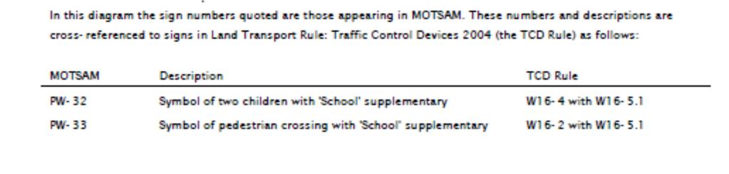
104 Appendix Figure 2: Typical Layout of a 40km/h Speed Zone for a school 104 P a g e

105 60km/h Variable School signs A 60km/h speed sign is used to lower a posted speed limit around rural schools when the permanent speed limit is 80km/h or 100km/h. Most of the activity outside a rural school is the parking and manoeuvring or turning of vehicles as parents and caregivers drop-off or pick-up their children. A measure that has proven successful in lowering speeds outside schools is active school warning signs (without speed advice). A 40km/h variable speed limit in school zones is intended for installation in urban or semi-urban areas where the permanent speed limit is 70km/h or less (previous section). In areas with a speed limit over 80km/h it is unlikely that motorists will slow to 40km/h within the short length of a school zone. Therefore a 60km/h variable speed limit is probably more appropriate. Background Land Transport Rule: Setting of Speed Limits 2003 requires the Transport Agency to approve any variable speed limit before a road controlling authority can make a bylaw to set such a speed limit. Warrant The general requirements for the use of 60 km/h variable speed limits are the same as for 40 km/h speed limits, with the following differences: The supplementary signage for 60 km/h variable speed limits should read School A 60 0 km/h variable speed limit should be used where the main risk is for side impacts with turning traffic, where there is little or no pedestrian activity on or next to the road. Typically, these speed limits apply to rural schools where traffic turns into and out of the school grounds. A 60 km/h variable speed limit is to be used where there is a permanent 80 km/h speed limit or where the mean operating speed is naturally lower than 100 km/h Ideally, a 60 km/h speed limit is desirable, however a 70 km/h variable speed limit may be used in high speed environments where compliance with a 60 km/h speed limit may be difficult. Other Measures Regardless of the criteria upon which an 80km/h speed limit is justified, it is essential that it operates safely with mean speeds at or below 80km/h. Some other measures will probably be necessary to achieve good compliance with a permanent 80km/h speed limit at a rural school: Thresholds (Toolbox ES2). Lane narrowing (install median or increase shoulder width Toolbox RS3). Textured and or coloured road surface (Toolbox SU1 and SU2) Vertical elements, e.g. thresholds and planting, but care is necessary to avoid restricting sight lines that might obscure pedestrians in the school zone. Speed indicator devices, publicity and education (Toolbox AS4 and AS5) Enforcement. The New Zealand Transport Agency s Safer Journeys to Schools provides more information on rural schools and a hierarchy of measures which include these types of signs.. Weather Activated and Congestion Activated Warning Signs Weather Activated Signs Weather Activated warning signs are currently under a trial process. Their use is not specified within current legislation so further information or approval to be used should be sought from the NZ Transport Agency. 105 P a g e
106 The purpose of these signs is to achieve safe and appropriate speeds in adverse weather conditions. The signs will typically reduce the speed from 100km/h to 80km/h or 60km/h depending on risk. The signs will also be able to display a wider range of speeds from 30km/h to 100km/h in extreme weather, or other hazardous events. Note, further specifications on the use of these signs are being developed. 106 P a g e
107 SPEED THRESHOLDS A threshold treatment may be necessary to reinforce a change on the speed limit where there is no obvious change in the road environment (Schedule 1, SLNZ). A threshold sign is a combination of a speed limit sign and a place name sign. Thresholds are located at interface between rural and urban areas and consist of physical and optical narrowing of the roadside to form pinch points. When designed correctly, thresholds lead to a reduction in vehicle speeds, as drivers perceive a change in the road environment ahead. Given the clearly established correlation between vehicle speeds versus crash severity and the increased exposure to risk, it is desirable to reduce traffic speeds to appropriate levels at the outer fringe of an urban area. Thresholds are a potential traffic management technique when one or more of the following conditions are present: vehicle speeds on the town outskirts or through the urban areas are inappropriately high all reported injury crash rates are higher than average or need to be reduced when vulnerable road users such as pedestrians and cyclists feature in the crash analysis. They should only be installed on roads that have a difference in the warranted speed limits of 20km/h or more at the rural/urban interface. Application and threshold treatments Used when entering a speed restricted area. I.e. where the posted speed limit is less than 100 km/h, an RG-1 speed limit sign must be installed on each side of the road, to inform drivers of the speed limit change. Where this change occurs at the entrance to a town a PN-1 place name sign is normally also provided, but installed separately from the RG-1 sign. Threshold signs may be used in association with threshold treatments (refer to Section 2 below) on the approaches to speed restricted towns, to make drivers more aware of a speed restriction and the start of a lower speed environment. To avoid duplicating information on the approaches to towns, existing (GD11) PN-1 place name signs must be removed when threshold signs are installed. To ensure threshold signs retain their effectiveness they shall only be used where there is a proven need to install thresholds. Threshold treatments alter the driver's perception of the road environment ahead and increase the effectiveness of speed limit reduction signing. Each threshold site design will vary depending on the combination of threshold treatments used, and must be designed specifically to suit its needs. A threshold sign consists of a RG-1 speed limit disc and a place name displayed on a rectangular reflectorised sign plate (backing board). No other message shall be shown on a threshold sign because it will effectively reduce its main function. The speed limit disc must be positioned above the place name to make it more noticeable from a distance, and to ensure that drivers will be made aware of the speed limit before they read the place name, because signs are usually read from the top down. The speed limit applying on the exit from the town should be shown on the reverse side of a threshold sign. Refer to TCD Part 1 sign details 107 P a g e
108 Rural- urban thresholds Where rural and urban areas meet, road controlling authorities can be under pressure to extend the urban speed limit to a point well outside the length justified by normal criteria (set out in Land Transport Rule: Setting Speed Limits 2003). Experience has shown that speed restrictions that can t be justified by normal criteria are rarely effective. Speed at the rural-urban threshold Local residents argue that drivers don t start to slow down until they ve reached the speed limit sign, meaning speeds entering the urban area are much higher than the limit. While their concern is justified, extending the speed limit doesn t produce the desired response and has sometimes led to an increase in speeds. In some instances a small length of an intermediate speed limit may be justified (in terms of normal speed limit policy), this has been found to have some beneficial reduction in speed. However, where the intermediate speed limit can t be justified by the speed limit policy, the effect, if any, can be negative. The most effective limits are those drivers can see are justified and which are clearly sign posted. Options for rural-urban threshold speed limit If the measured entry speeds into an urban area are high (compared with similar locations elsewhere), and neither an extension to the urban speed limit nor a transitional speed limit is justified (in terms of the normal speed limit policy), the following options should be considered: Ensure the speed limit signs are clearly visible. The signs should be visible to approaching traffic for at least 120 m and preferably 200 m or even more. Mark the speed value on the road surface (see Transport Agency s Manual of Traffic Signs and Markings Part II Section 4.01) If the speed limit sign is not already duplicated, place an additional sign on the right hand side of the road Consider increasing the size of the speed limit sign/s. Normally they should be at least 750 mm in diameter and may increase to either 900 mm or 1200 mm If the following criteria apply a 'speed restriction ahead' sign may be considered where a transitional speed limit does not exist site restrictions mean the signs can't be effectively duplicated or increased in size where traffic volumes, speeds and other factors justify installation, consider a threshold treatment in accordance with Guidelines for urban-rural thresholds. Traffic signs at thresholds The Speed Limit threshold permanent regulatory sign must conform to the layout of the Example Sign depicted in the diagram below and be in accordance with that described in Appendix Table 10.. Note theses signs are not included on the Traffic Specification website; however the information is provided within the Traffic Control Devices Rule (Schedule 2) so the following information has been provided in Appendix Table 10 and a typical layout provided in Appendix Figure P a g e


109 - Appendix Figure 3: A typical layout of a threshold and visual impact of a before and after view Design considerations Location Overseas case studies indicate urban-rural thresholds achieve their greatest speed reductions when used on roads with very high approach speeds before the threshold was installed. Speed reductions are lower when thresholds are located at or near physical features in the road that limit speed, such as a blind bend or summit. To enhance the threshold effect, threshold signs should be prominently displayed on both sides of the road and there should be no longitudinal offset between the two signs. Threshold signs must normally be located within ±20 m of the legally defined positions for the RG-1 regulatory speed signs and where approaching drivers have an uninterrupted view of them for at least 120m. Threshold signs are generally larger than other signs. Care should be taken to make sure that the signs do not obscure drivers' view of any other signs, or any access located near the signs. Where signs in their legally defined position range are likely to obstruct turning traffic into nearby side roads or intersections, they should be relocated but the new locations must be gazetted. 109 P a g e
110 Location relative to a warranted speed limit Any speed restriction signs in the threshold must be located within 20 metres of the start of the warranted speed restriction. Guidelines for Setting Speed Limits sets out the warrant details. Road users are more likely to comply with a speed limit if it is consistent with the level of roadside development along the road and the road function. In some cases it may be necessary to carry out speed restriction surveys to ensure the correct speed limit is in force and the signs are located in the correct position. Location relative to multiple speed limits leading into town Some locations have progressively reducing speed limits leading into the town centre such as 70km/h at the town outskirts followed by 50km/h. To determine where the threshold will be the most effective relative to these speed restrictions, an analysis of the crash history, the level of exposure of at-risk road users (such as pedestrians or cyclists) and speeds should be undertaken at the start of each speed limit area. If the problem occurs at the start of the higher speed limit, or at both the higher speed limit and the lower limit, the threshold should be located where the higher limit starts. To ensure that drivers continue to travel at a reduced speed through the urban area, the threshold treatment should be supported by traffic calming measures such as flush medians, selective verge planting, or similar. If the problem is confined solely to the start of the 50km/h area, the threshold should be located at the start of the 50km/h speed restriction. Location relative to property accesses and intersections Locating thresholds at the start of a warranted speed limit also means it will be close to the start of the road frontage development. Care must be taken to ensure the threshold does not interfere with sight lines from nearby properties or interfere with access to properties. The same considerations apply when the threshold is located near an intersection. Visibility to approaching drivers Thresholds are effective where approaching drivers can see them in time to adjust their speed to appropriate levels. Thresholds must be visible over at least the stopping sight distance for the 85th percentile of the approach speed Reference should be made to the Austroads Rural Road Design Guide for stopping sight distances. When thresholds are being located on large radius curves, careful siting is required to ensure they remain within the drivers cone of vision. Roadway narrowing An effective threshold involves creating a pinch point at the start of the urban area. By the appropriate use of horizontal and vertical elements, the roadway should be narrowed over a length of metres. The road width through this pinch point will vary depending on circumstances but must allow all entitled vehicles to pass through it. If the road is part of a designated over dimension route, a minimum horizontal clearance of 10.5 metres between vertical elements is recommended. If wider loads are to be catered for, the sign mountings can be of a flag type where the entire sign can rotate about a vertical axis when needed. The Over dimension Permit Issuing Agency or the NZ Heavy Haulage Association can be contacted for details of expected load widths. Appendix Figure 4 and Appendix Figure 5 shows recommended minimum road and lane widths plus lateral clearances through typical threshold pinch points. Horizontal elements Horizontal design elements are used to reinforce the road narrowing effect at pinch points. Wherever road width permits, the sealed width should be narrowed by installing solid build-outs such as kerb, but where this is not possible then pavement markings may be used to create the pinch point effect. European studies have found median 110 P a g e

111 islands (especially those with trees or shrubs) improve the visibility of the thresholds, interrupt the forward view, and reduce the optical width of the carriageway. Solid median islands must be clearly delineated so they are visible both night and day to approaching motorists. Islands that are not clearly visible become a potential hazard, particularly to any overtaking vehicles. Solid median islands should only be used at thresholds located at the start of 50 and 60km/h speed restrictions. Raised retro-reflective pavement markers (RRPMs) should be used on all transitional approaches to solid build outs or solid median islands in threshold pinch points. Appendix Figure 4: Minimum roadway, lane widths and lateral clearances where a centreline is marked NOTES Appendix Figure 5: Minimum road, lane widths and lateral clearances where a solid median is used * A 6.5m minimum combined lane-width provides for two maximum legal width vehicles (2.5m wide body m wide wing mirrors) to pass whilst staying within their lane. ** The 4.5m width is recommended where cycles pass through the Pinch Point to allow for clearances (refer Austroads Guide No 14 Bicycles ). This can be reduced to 3.8m width where cycles have separate lanes outside of the pinch point. *** Solid median islands should be at least 1.75m wide to allow 0.75m RG 17 signs to be installed with 0.5m lateral clearance each side (refer to Part 5 of the TCD Manual). **** Parking should be prohibited within the pinch point areas ***** a marked lane has to be at least 2.5 metres wide. Pavement markings such as diagonal shoulder markings can be used to narrow traffic lanes and also give an optical illusion of a narrow carriageway. Likewise, a flush island or median markings can be used in the pinch point areas where lane narrowing is required but a solid median island is not suitable. RRPMs are recommended as follows: 111 P a g e
112 Red RRPMs on transition edge lines leading into marked pinch points and on the edge line through the pinch point itself White RRPMs on flush median markings used in threshold pinch points (re refer to Part 5 of the TCD Manual for set out details Yellow RRPMs on the tapers leading up to solid median islands Appendix Figure 6 and Appendix Figure 7provide examples of threshold pavement markings. Lateral clearance Threshold signs should be located as close as practicable to edge of the roadway, to enhance the narrowing effect of threshold treatments. However, the standard minimum lateral clearances between a sign and the edge of the trafficable carriageway, traffic lane or shoulder as applicable, must be provided in all cases. A minimum lateral clearance of 10.5 metres between signs must also be provided on state highways, for the passage of over dimension vehicles, i.e. the inner edge of threshold signs should be located at least 5.25 m from the road centre line. This lateral clearance is adequate for most over dimension vehicles, but will not cater for extreme cases. Where no alternative route is available for extreme over dimension vehicles threshold signs must be readily demountable or have a swivel mechanism to rotate the signs through 90 degrees, to increase the clear distance between signs and enable these vehicles to pass through the threshold treatment. A 3.5-m lane width is normally necessary to maintain % standard lateral clearance between vehicles in adjacent lanes. Lane width may however be reduced to 3.0 m at threshold treatments, to enhance their visual narrowing effect. This may be achieved by providing a 1.0 m wide % painted central median centred on the existing road centreline and reducing the standard lane width by 0.5 m. Reflective raised pavement markers (RRPMs) may be placed on the painted median to maintain the visual constraint at nights, and especially when the pavement is wet. Marking layouts for thresholds with: flush median and centrelines are provided in Appendix Figure 6. solid island and kerb build-outs are provided in Appendix Figure P a g e


113 Appendix Figure 6: Marking Layout for thresholds with Flush medians and centrelines NOTE * Merge tapers to be set out as shown in Part 5 of the TCD Manual 113 P a g e


114 Appendix Figure 7: Marking Layout for thresholds with solid island and kerb build-outs NOTE* Merge tapers to be set out as shown in Part 5 of the TCD Manual P a g e

115 Vertical elements Vertical elements must always be used as they improve the visibility of the threshold to approaching drivers. Examples of vertical elements include trees and shrubs, combined speed restriction and place name signs, and the structure or poles that support these signs. Street lighting can also be incorporated as a vertical element. Trees, lighting poles, and poles used to support signs in the threshold area must be frangible. Any trees should have a trunk diameter of less than 100 mm when measured 400 mm above the ground, and should not be hardwoods. Service poles or lighting columns should either be mounted on a slip base that breaks on impact or made of energy absorbing materials. Any unprotected, non-frangible structure within 9 metres of the edge of the carriageway should have hazard markers attached. Research indicates drivers travel at a reduced speed where the height of vertical features is greater than the width of the street. Appendix Figure 8and Appendix Figure 9both illustrate how the optical width of a road should be less than the optical height to help encourage reductions in speeds. Appendix Figure 8: Optical width where width is greater than height and encourages speed (Source: Devon County Council Guidelines) Appendix Figure 9: Optical width where height is greater than width and helps reduce speeds Lighting Street lighting is an important safety element in rural threshold design and: Should always be provided where a solid central island is part of the threshold design (either as a continuation of street lighting or isolated flood lighting at the threshold) Is desirable where solid build outs are used Is optional at thresholds where only pavement markings have been used. Extending street lighting out to the threshold highlights to road users that they are entering an urban area. The lighting poles themselves are a valuable visual cue of an urban area even in daylight hours. 115 P a g e
116 Conspicuity Unless thresholds stand out from the surroundings, road users may not notice the approaching change of environment and fail to reduce speed as required. In addition to the vertical and horizontal elements described above, there are a number of measures that can enhance conspicuity. Daytime conspicuity Measures that enhance daytime conspicuity include: Bright coloured flowers or shrubs as part of the landscaping Trees or shrubs that contrast in colour with the surrounding landscape Coloured paving materials through the threshold pinch point (see Section below) Size and colour of the combined speed limit and place name sign. Night time conspicuity In addition to the use of RRPMs and street lighting referred to Sections above, night-time conspicuity of the threshold can be enhanced by using reflectorised paint or reflective strips on all kerbs used in build outs or median islands. Provision for cyclists or pedestrians Two methods of catering for cyclists or pedestrians at thresholds are: Allowing room for these road-users to travel within the pinch point, or Providing a separate path outside of the pinch point. Catering for cyclists or pedestrians within the pinch point area increases the overall width required and may result in the threshold achieving lesser speed reductions. Measures to address this include increasing the height of the vertical elements to reduce the optical width or installing a median island. The construction of separate paths outside of the pinch point area would provide greater safety for cyclists and pedestrians and improve the effectiveness of the threshold in reducing speeds. However, the cost of the project is likely to increase. Changes in pavement surface The use of a different pavement surface or texture at the pinch point may be considered as part of the overall threshold design. If a change in surface texture is proposed, care must be taken to ensure that the skid resistance of the carriageway is not compromised. Surface or texture Schnull & Lange (1992) noted that changes in road surface to rougher materials led to distinct speed reductions, especially in the higher speed range. However, nearby residents complained about the increase in noise level. Steinbrecher described two alternative design techniques using paving stones at thresholds as a contrast to the normal asphalt road surface. The first used strips of pavement stones at the edges of the threshold to achieve further optical narrowing of the road. The second used pavement stones across the full width of the threshold alerting motorists of the change in environment immediately ahead by an increase in noise level. This design was curtailed after nearby residents found the shift in noise frequencies as vehicles drove over the paving stones to be unpleasant. 116 P a g e
117 Rumble strips Increases in noise levels of up to 9 decibels have been recorded where rumble strips were installed, and they have not found favour with residents living nearby. Vertical carriageway shafts The use of speed humps or vertical carriageway shifts within rural thresholds is not recommended. Overseas research indicates that these vertical deflections of the carriageway could create a safety hazard that would cause many more problems than existed previously. Landscaping and roadside verge treatment Trees and shrubs planted adjacent to pinch points will often make up a substantial part of the vertical elements used in rural thresholds. These can be complemented either side of the pinch point with low shrubs and ground cover planting to add to the closing in effect. All trees or shrubs planted within 10 metres of the carriageway edge line must be frangible. Frangible trees require a trunk diameter at maturity of less than 100mm measured 400mm above ground, and should not be hard wood. The trees or shrubs should not interfere with sight lines between oncoming vehicles and the access points of any nearby properties and intersections or conceal pedestrians. Where it is not possible to position trees without obstructing sight lines, the trunks should be trimmed of branches to a height of 2.5 metres above ground level allowing visibility either side of the trunk of the tree. Trees and shrubs used as vertical elements in the threshold should be of an evergreen variety as the seasonal loss of leaves can reduce the conspicuity of the threshold and the road narrowing effect. Care should be taken to ensure trees and shrubs do not cause undue shading of the roadway, especially in areas prone to ice or frost in winter. Urban-urban thresholds An urban to urban threshold is one that is located in areas where posted speed limits are less than 70km/h and the difference in the speed changes are smaller than the rural to urban sites. With this in mind it is likely that a full threshold may not be needed unless there is a need to reduce speeds to a significant level i.e. a70km/h drop to a 30km/h drop in to a shared space are or like. Urban-urban thresholds can also be local area traffic management treatments such as an entry treatment in to a lower volume/access side road The Speed Limit threshold permanent regulatory sign must be in accordance with that described in Appendix Table 9. Note theses signs are not included on the Traffic Specification website and a typical specifications are provided in Appendix Table 10. Rural -rural threshold A rural to rural threshold is one where the speed limit may differ between a 100km/h, 90km/h or 80km/h speed limit. If you need to highlight this change more than with a normal speed limit roundel sign, large roundels or small white backing boards could be considered. It is generally not necessary to provide full threshold treatments at these sites. Consultation During the design stages of a threshold treatment it is important that consultation takes place with all likely road user groups in the area as well as with adjacent landowners and other interested parties. The following check list can be used as a guide: Adjacent residents, farms, businesses Police, ambulance, fire brigade NZ Road Transport Forum and NZ Heavy Haulage Association 117 P a g e
118 NZ Automobile Association Cycle clubs/groups/associations Nearby schools, colleges, and rest homes Iwi and hapu Network utility operators Speed measurements Measurements of speed at urban entry points are necessary to confirm or counteract local perceptions, to provide a database of results to determine expected or achievable speed profiles, and to evaluate the impact of any changes made to signs or the roadside environment. If the changes have not had the desired effect it may be necessary to introduce other measures or modify the existing design. Not only may the surveys help in determining the need for implementing further options they may assist in implementing or prioritising speed enforcement. Speed surveys should note the mean and 85th percentile speeds (with standard deviation) for each travel direction. At least three of the four sites below should be surveyed before construction, within two months of completion, and again one year after completion. If only three sites can be measured, site (d) should be excluded. 200 metres outside of the threshold location at the threshold 300 metres inside the threshold 600 metres inside the threshold Manual speed surveys are recommended as providing the most accurate and reliable information for before and after comparisons of vehicle speeds. If automatic speed measuring equipment is used, free flowing speeds of all vehicles should be recorded for each direction of travel independently for a seven day period. 118 P a g e
119 DESIGN, LOCATION AND SITING OF SPEED HUMPS Permanent Road Humps A road hump is defined in the TCD rule as being a short, elevated portion of roadway used as a means of reducing the speed of vehicles travelling on a road way. The term road hump or speed hump are commonly interchanged. In some case the term judder bar is used, however this is a different form to a speed hump and is generally a roughly formed latitudinal projection of the road surface. It should be highlighted that a road/speed hump is not a judder bar but it is a device designed to control speeds to defined limits while minimizing potential hazards. [TEIB No. 2] Manual of uniform traffic control devices - Local area traffic management,, (AS( ): specifies two types of road humps: The Watts profile (an example is provided in Appendix Figure 10which has a circular arc cross section and is of fixed length (in the direction of travel. Approximate dimensions are included inappendix Table 16. The flat-top hump (or platforms) as shown in Appendix Figure 11. In addition a variation on these profiles are used to provide speed cushions to allow wider wheel based vehicles (such as emergency services vehicles travel through the hump without delay. Further information on platforms is included and is also provided in the NZ Transport Agency s Pedestrian and Planning Design Guide. For information on temporary speed humps refer to Toolbox TM2) and the NZ Transport Agency s Code of Practice for Temporary Traffic Management (COPTTM) Appendix Figure 10: Watts profile road hump (Source: AS ) t (mm) h (mm) Notes: Appendix Table 16: Dimensions for Watts profile road hump At ramps at entry points to shared zones (see AS ) the ramp grade should be increased to between 1 in 2 and 1 in 4 The design speed for a hump appropriate on public streets is 20 km/h The profile of raised pedestrian crossing (zebra) is different from these profiles Refer to Appendix Figure 13 and the NZ Transport Agency s Pedestrian and Planning Design Guide and AS ). Where it is expected that a large number of heavy vehicles will cross a hump the watts profile can be modified by increasing the longitudinal length to 5.0m or consider using speed cushions. 119 P a g e
120 The Auckland Transport Code of Practice, Chapter 8, Traffic Calming Devices and Local area Traffic management (LATM) states that Speed humps are generally 100mm in height and must have a longitudinal length of 3700mm (5000mm for the modified Watts profile) spaced fit for purpose, but typically 80m to 120m apart min Appendix Figure 11: Flat-top hump profile (Source modified version AS ) For information on cross sections and design of speed cushions refer to the Auckland Transport Chapter 8 -Traffic Calming, Drawings. In addition the NZ Pedestrian Planning and design guide provides dimension for typical pedestrian platforms as shown in Appendix Figure 13. Criteria to install Three main factors should be taken into consideration when determining the use of a road hump. These are: Speed Volume Traffic composition For further detailed information on the consideration of speed, volume and traffic composition, use TEIB No.2 and AS , Austroads part 8. These documents also both summarise the criteria for installing road humps on a street is shown in Appendix Table 17. The street should: The street should not: be within a current 50km/h or lower speed limit be a principal or arterial traffic route area have an up gradient of more than 8% (this is due to difficult be primarily a local residential street or limited for heavy vehicles to negotiate if forced to stop and drainage collector function with a general road network on the elevated side can become an issue. consistent with the maintenance of low speeds be greater than 1000m in length (except in exceptional have suitable alternative routes to absorb any likely circumstances) diverted traffic be a main bus route (however it could be satisfactory for low have traffic volumes less than 400vpd in peak frequency, long flat-top humps are used or school bus route) hours have abutting land use which is predominantly retail/commercial or industrial not have more than 50vpd HCV volumes be used extensively for access to emergency vehicle establishments, high residential developments of public meeting places Appendix Table 17: Criteria for road humps 120 P a g e
121 It is also important to note that if road humps cannot be seen sufficiently in advance, vehicles could cross them at speed, resulting in public complaints or dangerous vehicle manoeuvres. As stated in TEIB Watts Profile humps have been used successfully in streets carrying up to 8000 vpd; however, where the speed and volume criteria below are properly applied, it is unlikely that streets with volumes in excess of 3000 vpd will warrant humps. Normally, only street with volumes less than 1000 vpd should be treated Signs Where a permanent road hump and speed cushions are, the signs shown in Appendix Table 13 should be used. Refer to Typical layouts provided further in this section. Markings and layouts If they are marked with a zebra type crossing they must be marked and signed in accordance with the NZ Transport Agency s Traffic Control Devices Rule Some typcial layouts are provided for later in this in section ; however some markings can be used on road humps; including dragons tooth (Appendix Figure 12) ; and hatching types (Appendix Figure 13). Appendix Figure 12: Typical marking plan for both watts (sinusoidal) and flat profile road hump (Source: Chapter 8 (Auckland Transport Code of Practice - modified) 121 P a g e


122 Zig-Zag markings -150mm wide - Appendix Figure 13: Typical dimensions of a pedestrian platform and layout of markings [Source NZ Pedestrian and Planning Design Guide. For information on cross sections and desing of speed cushions refer to the Auckland Transport Chapter 8 -Traffic Calming, Drawings. If they are marked with a zebra type crossing they must be marked and signed in accordance with the NZ Transport Agency s Traffic Control Devices Rule ( Good guidance on the placement and design of road humps is provided in the New Zealand Pedestrian and Planning Design Guide, ( P a g e

123 RURAL INTERSECTION ADVANCED WARNING SIGNS (RIAWS) This information follows an earlier information sheet (July 2012) 1 which introduced the Rural Intersection Active Warning System (RIAWS) concept and trial. This information sheet provides information on the outcomes of the trial, guidance for road controlling authorities (RCAs) regarding the appropriate conditions and the correct use of the RIAWS, and the bylaw and gazetting requirements for the variable speed limit. Background Improving the safety of high-risk intersections is a strategic priority under the government s Safer Journeys road safety strategy and the two action plans that have followed. The High Risk Intersection Guide 2 outlines that intersection crashes accounted for 38% of all injury crashes on New Zealand roads between 2006 and Furthermore, 17% of all reported injury crashes at intersections were fatal or serious crashes and a greater proportion of fatal intersection crashes tend to be at rural locations. The implementation of RIAWS is part of a wider programme to address safety at high-risk intersections and ultimately deliver on the Safer Journeys strategy. Rural intersection crashes mostly involve turning and crossing vehicles colliding with high speed through traffic. A Safer Speeds alternative to reconstruction is considered to be an appropriate method to treat high risk intersections should funding not be readily available for transformational works such as a rural roundabout. However a permanent speed restriction at such sites is often not appropriate as a lack of land-use development in rural locations would mean that road user understanding and therefore compliance with permanent and static signage would be poor. RIAWS have the potential to reduce the number and severity of crashes at rural intersections by: Slowing road users on major road intersection approaches and thus reducing crash likelihood (effectively increasing available stopping distance) and severity (less energy on impact) Increasing awareness and therefore preparing road users for a possible event (effectively reducing reaction time) Improving road users gap judgement (accepting longer gaps) on minor road intersection approaches Outcomes from the RIAWS trials A systematic process of development led to the current design of RIAWS and they have now been trialled at ten rural intersections around New Zealand. Where variable speed limit signs have been installed, substantial reductions in traffic speed through the intersections have been achieved when the system is activated. This has held true over the medium term (10 to 24 months) following implementation. 123 P a g e
124 Appendix Figure 14: Source Mackie Consultants, 2015 Other findings were: The 70 and 60 km/h signs proved significantly more effective in slowing traffic than the Slow Down signs and all trial sites now have 70 km/h signs, except one which has a 60km/h sigh (Pakaraka, Northland). At the initial pilot site at Himatangi, an increase in the mean value of critical gaps was measured when the RIAWS was active, indicating a potential safety benefit Positive road user comprehension and support for RIAWS, measured through a survey Based on previous crash rates, after 11 months following RIAWS installation, approximately 12 crashes would be expected at the first six intersection sites, with four or five injury crashes. In comparison, since RIAWS installation there have been a total of four crashes at these sites, with one injury crash. Clearly more time will be needed to more confidently understand the casualty reduction performance of RIAWS For more information see the full RIAWS trial report4 Use of RIAWS following the trial Following the successful trial which is now complete, RIAWS can be used operationally around New Zealand. However, it is important that RIAWS are only used at appropriate intersections, the implementation and operation is consistent with the trials and specification document 4 and appropriate monitoring and system maintenance is carried out. The following sections outline some key considerations in more detail. Required approval Approval for the use of RIAWS at all State Highway sites is required from the National Traffic and Safety Manager (currently Fergus Tate). For all sites the variable speed limit must be gazetted by the Transport Agency, delegated via the Network Manager (currently Glenn Bunting). Site Selection To help with the selection of suitable sites for RIAWS, criteria have been developed and confirmed within the trials and should be applied to new sites for on-going operational use. 124 P a g e
125 A High Collective Risk Intersection in accordance with the HRIG Evidence of crash codes compatible with objectives of RIAWS, i.e. turning or crossing vehicle vs vehicle crashes Swedish research indicated a maximum of up to 10,000vpd on the main road and 2,000 vpd on the side road approaches, for using a system such as RIAWS. If traffic volumes are very high, the signs may be on for a high proportion of the day, which reduces the systems credibility. Main road mean operating speeds of km/h Issues with visibility on the approach from the intersection s side roads (could be too little or too much) Relatively simple geometry (T or X), without complicating factors such as multiple lanes on through road (excepting that many intersections have acceleration lanes and right turn bays) No planned works in short to medium term. Longer-term may be OK as RIAWS may provide a good interim solution (to a rural roundabout for example) Important considerations There are a number of important considerations if successful performance of RIAWS at an intersection is to be expected, including: Checking that the site is suitable for RIAWS (using the criteria outlined above) Checking the various logistics issues of installing RIAWS experience of supplier and quality of hardware, power supply, radio signal etc. Selecting the speed limit. The trial was mostly based upon 70km/h, for which good compliance and outcomes have been demonstrated. There may be situations, such as low existing operating speeds, or where an existing permanent speed limit of 80 km/h or lower exists, which would justify a lower variable speed limit for RIAWS. In any case, the required approvals outlined above are needed. The timing of the sign activation so that potential side-impact collision situations are protected by the variable speed limit The locations of existing signage and any re-arranging that may be needed Systematically checking the correct function of RIAWS immediately after it becomes operational Ensuring that monitoring and maintenance systems are in place to minimise the likelihood of a fault and any down time following an outage. Checking the performance of RIAWS following installation using sign activation data, speed surveys and eventually crash records. Please refer to the document Specification and reference manual for NZ Transport Agency Rural Intersection Active Warning System 4 for a full account of the higher level and technical requirements for RIAWS. Note that the Warning system layout needs to be accordance with the trial layout. 1 Rural Intersection Activated Warning Signs. NZ Transport Agency Information Sheet, July Mackie, H.W. The effects of speed on rural intersection crashes. A report prepared for the NZ Transport Agency by TERNZ Ltd, Mackie, H.W. and Scott, R. Rural Intersection Active Warning System (RIAWS) Trial Final Report. A report prepared for NZ Transport Agency by Mackie Research & Consulting, April Holst, K and Russell, M. Specification and reference manual for NZ Transport Agency Rural Intersection Active Warning System, NZ Transport Agency, December High Risk Intersection Guide, NZ Transport Agency, P a g e

126 SAFER SPEED AREA, SHARED ZONES Safer Speed Areas Safer Speed areas are located in zones where a common reduction in speed is applied to an overall area or main corridor with connecting roads rather than an individual road. There are a range of safer speed limits which generally include both urban and rural areas: Safer speed areas are currently limited to demonstration or trial sites within New Zealand that had a higher number of crashes or other specific safety issue; however even though only a few safer speed areas exist they reflect the intent of current Safe Speed Management messaging in terms of a safe system approach. The Safe System approach focuses on reducing risk and minimising harm. In the context of speed management, this means that on roads, or in areas, where the infrastructure doesn t provide for safe travel at certain speeds, and the investment is not available to improve the infrastructure, then operating speeds must be revised to mitigate death and serious injury resulting from a crash. This suggests that a risk assessment process is the appropriate way to determine what speed limit is suitable for a road or an area. Clause 3.2(5) of the Speed Limits Rule enables a RCA to set a speed limit that differs from the calculated limit, provided the RCA can demonstrate that the speed limit would be safe and appropriate considering the function and use of the road and its surrounding environment. A risk assessment of the network is the best way to obtain information to satisfy this requirement of the Rule. Shared Space - - Examples of Safer Speed Area Signs - Rule Code (R1-5.5) A space that is designed for various road users to share one space. Pedestrians have right to use full road width and drivers are encouraged to travel at low speeds through the use of various measures. Drivers give way to pedestrians who, in turn, should not impede traffic. (The Transport Agency - The Official New Zealand Road Code - Sharing the Road). Refer to the Toolbox for general information on shared space. Under clause 10.2 of the Land Transport Rule Road users, responsibilities for shared zones are: (1) A driver of a vehicle entering or proceeding along or through a shared zone must give way to a pedestrian who is in the shared zone. (2) A pedestrian in a shared zone must not unduly impede the passage of any vehicle in the shared zone. In relation to the types of traffic control devices used in shared space. They can be: Signs Markings Coloured pavements or pavers Planting Physical features (kerbs, medians, road humps, blocks or bollards 126 P a g e
127 Generally if a shared space is defined, then it should be signed using the shared zone sign A40-7 (Rule Code). Detailed specification on this sign can be found within the Transport Agency s traffic sign specifications website; Generally where shared spaces are used and designed appropriately will negate the need for any additional signs and markings. However where there are parking or speed limit restrictions however these will need to be signed in addition to the Shared Zone A40-7 (Rule Code). sign P a g e


128 TYPICAL ARRANGEMENTS FOR LATM DEVICES Appendix Figure 15: Side road threshold treatment Notes: This diagram has been modified from Figure 3-1 of AS Manual of uniform traffic control devices; Part 13: Local Area Traffic Management. All appropriate design standards should be met to allow turning vehicles into and out of the side road Refer to Toolbox IN1 regarding the use of regulatory signs Refer to Toolbox IN2 regarding the use of stop or give way controls Regarding the use of tactile markings refer to RTS 14: Guidelines for facilities for blind and vision impaired pedestrians and the NZ Transport Agency s Pedestrian and Planning Design Guide Traffic Islands should be designed in accordance with appropriate standards and signed in accordance with advice provided in NZ Transport Agency s Traffic Control Devices Manual Part 4: At Intersection and Part 5: Between Intersection For more information on street name signs refer to NZ Transport Agency s Traffic Control Devices Manual Part 2: Direction, Service and General Guide signs or local council policy specifications. Contrasting pavement materials should have similar skid resistance to surround pavement for the benefit of bicycles and motorcycles [AS ] 128 P a g e

129 Appendix Figure 16: Road Hump Notes: This diagram has been modified from Figure 3-2 of AS Manual of uniform traffic control devices; Part 13: Local Area Traffic Management Sign WN2 can be used with a speed advisory supplementary if the area scheme or surrounding environment does not provide enough visual clues to help drivers slow on approach. Refer Appendix Table 15 The profile shown is platform type and is a better option than the watts profile ( see the Technical Specifications of this guide and traffic calming measure in the Toolbox for assisting active and mobility impaired road users to cross the road. The platform or speed hump may be used in conjunction with other horizontal displacement devices such as kerb build-outs shown in Single Lane slow point. 129 P a g e

130 Appendix Figure 17: Low volume/access and small diameter roundabout (operating speeds less than 30km.h)) Notes: This diagram has been modified from Figure 3-5 of AS Manual of uniform traffic control devices; Part 13: Local Area Traffic Management Where the operating speeds on approach and on the roundabout are likely to be 30km/h or lower due to other traffic calming measures then signs and markings normally required for a roundabout are not needed( Sub Clause of the land Transport Rule Traffic Control Devices, 2004) Alternative road markings can be considered on approach to the traffic island (Appendix Figure 21) All other signs and markings in relation to roundabouts in general can be found in the NZ Transport Agency s Traffic Control Devices Manual Part 4: At Intersections 130 P a g e

131 Appendix Figure 18: Single Lane slow point Notes: This diagram has been modified from Figure 3-6 of AS Manual of uniform traffic control devices; Part 13: Local Area Traffic Management A road hump, chicane, slow point or other channelling device, on or adjacent to a road, that is intended to reduce the travelling speed of vehicles must be illuminated or have reflective delineators or reflective signs installed so that the structure is visible. There is no need for additional hazard markers or other reflectorised signs if lighting is adequate within the area and visibility of any island within the road is satisfactory. Refer to Toolbox IN1 regarding the use of regulatory signs No stopping lines are used only when needed i.e. where there is a need to mark for an underlying road user rule requirement such as parking within1m of a driveway. Or you need to improve sight visibility to the islands. Consideration needs to be given to the vehicle type using the road and access for both emergency and service vehicles. 131 P a g e

132 Appendix Figure 19: One lane with Driveway link Notes: This diagram has been modified from Figure 3-7 of AS Manual of uniform traffic control devices; Part 13: Local Area Traffic Management Refer to Toolbox IN1 regarding the use of regulatory signs Depending on the length of the driveway link and any visibility constraints, consideration may need to be given to providing some pull off areas for vehicles to pass. A road hump, chicane, slow point or other channelling device, on or adjacent to a road, that is intended to reduce the travelling speed of vehicles must be illuminated or have reflective delineators or reflective signs installed so that the structure is visible. There is no need for additional hazard markers or other reflectorised signs if lighting is adequate within the area and visibility of any island within the road is satisfactory. Contrasting pavement materials should have similar skid resistance to surround pavement for the benefit of bicycles and motorcycles [AS ] 132 P a g e

133 Appendix Figure 20: Single Lane angles slow point Notes: This diagram has been modified from Figure 3-8 of AS Manual of uniform traffic control devices; Part 13: Local Area Traffic Management Refer to Toolbox IN1 regarding the use of regulatory signs Special Consideration should be given to the provision of safe passage to bicycles. If provided behind the slow point, it should be able to be kept free from rubbish A road hump, chicane, slow point or other channelling device, on or adjacent to a road, that is intended to reduce the travelling speed of vehicles must be illuminated or have reflective delineators or reflective signs installed so that the structure is visible. No stopping lines are used only when needed i.e. where there is a need to mark for an underlying road user rule requirement such as parking within1m of a driveway. Or you need to improve sight visibility to the islands or make way for a cyclist if a safe passage for bicycles has been included in the scheme. 133 P a g e


134 Appendix Figure 21: Two lane slow point Notes: This diagram has been modified from Figure 3-9 of AS Manual of uniform traffic control devices; Part 13: Local Area Traffic Management Refer to Toolbox IN1 regarding the use of regulatory signs Alternative road markings on approach to traffic islands is shown in Appendix Figure 17 A road hump, chicane, slow point or other channelling device, on or adjacent to a road, that is intended to reduce the travelling speed of vehicles must be illuminated or have reflective delineators or reflective signs installed so that the structure is visible. Consideration needs to be given to the vehicle type using the road and access for both emergency and service vehicles. 134 P a g e


135 Notes: Appendix Figure 22: Modified T intersection This diagram has been modified from Figure 3-10 of AS Manual of uniform traffic control devices; Part 13: Local Area Traffic Management Refer to Toolbox IN1 regarding the use of regulatory signs Alternative road markings on approach to traffic islands is shown in Appendix Figure 17 Continuity lines may be need around the outside of the curve to help delineate the lanes but only if speeds are higher Consideration needs to be given to the vehicle type using the road and access for both emergency and service vehicles. All other signs and markings in relation to intersections in general can be found in the NZ Transport Agency s Traffic Control Devices Manual Part 4: At Intersections 135 P a g e

136 Appendix Figure 23: Full and Partial Road Closures Notes: This diagram has been modified from Figure 3-11 of AS Manual of uniform traffic control devices; Part 13: Local Area Traffic Management Refer to Toolbox IN1 regarding the use of regulatory signs Refer to Toolbox IN2 regarding the use of stop or give way controls All other signs and markings in relation to intersections in general can be found in the NZ Transport Agency s Traffic Control Devices Manual Part 4: At Intersections For more information on street name signs refer to NZ Transport Agency s Traffic Control Devices Manual Part 2: Direction, Service and General Guide signs or local council policy specifications. Where any road closures are proposed, consideration needs to be given to the vehicle type using the road and access for all road users, and emergency and service vehicles and alternative routes. 136 P a g e
APPENDICES RULE REQUIREMENTS, TRAFFIC CONTROL DEVICES AND TECHNICAL SPECIFICATIONS... 81
 Table of Contents A1... 1 TOOLBOX... 3 How to Implement Treatments and Activities... 3 Treatment Philosophy 3 Education and Communication 5 Key treatment philosophies 5 Hierarchy of measures 6 Treatment
Speed Limit Policy Isle of Wight Council
 APPENDIX B Speed Limit Policy Isle of Wight Council 2009 Contents Section 1 Introduction 1.1 Links with the Local Transport Plan Section 2 Speed Limits on Urban Roads and Residential Areas 2.1 20mph Limits
Discover the Safe System Approach
 Discover the Safe System Approach Aim Take you on a journey of discovery Inform, engage, enthuse and share with you the Safe System approach to saving death and injury on our roads Change to less graphic
Safe Speed programme ATTACHMENT 1. Randhir Karma, Group Manager Network Management and Safety
 Safe Speed programme ATTACHMENT 1 Randhir Karma, Group Manager Network Management and Safety 1 Why Safe Speeds? AT s strategic context National guidance AT has embraced Vision Zero principles and recognises
road safety issues 2001 road toll for Gisborne district July 2002 Road user casualties Estimated social cost of crashes*
 GISBORNE DISTRICT road safety issues July 22 The Land Transport Safety Authority (LTSA) has prepared this Road Safety Issues Report. It is based on reported crash data and trends for the 1997 21 period.
2003 road trauma for. Wairoa District. Road casualties Estimated social cost of crashes* Major road safety issues WAIROA DISTRICT JULY 2004
 WAIROA DISTRICT JULY 24 T he Land Transport Safety Authority (LTSA) has prepared this road safety issues report. It is based on reported crash data and trends for the 1999 23 period. The intent of the
CHAIR AND MEMBERS CIVIC WORKS COMMITTEE MEETING ON APRIL 25, 2016
 TO: FROM: SUBJECT: CHAIR AND MEMBERS CIVIC WORKS COMMITTEE MEETING ON APRIL 25, 2016 JOHN BRAAM, P. ENG. MANAGING DIRECTOR, ENVIRONMENTAL & ENGINEERING SERVICES AND CITY ENGINEER SCHOOL ZONE SPEED LIMIT
1 VicRoads Access Management Policies May 2006 Ver VicRoads Access Management Policies May 2006 Version 1.02
 1 VicRoads Access Management Policies May 2006 Ver 1.02 VicRoads Access Management Policies May 2006 Version 1.02 2 VicRoads Access Management Policies May 2006 Ver 1.02 FOREWORD FOR ACCESS MANAGEMENT
Resident s Toolkit Traffic Control Device Local Area Traffic Management
 Resident s Toolkit Traffic Control Device Local Area Traffic Management This booklet contains information on traffic control devices commonly used in South Australia. A traffic control device is a sign,
PAEKĀKĀRIKI HILL ROAD / BEACH ROAD / SH1 INTERSECTION PROGRESS REPORT
 Chairperson and Committee Members ENVIRONMENT AND COMMUNITY DEVELOPMENT COMMITTEE 6 DECEMBER 2011 Meeting Status: Public Purpose of Report: For Decision PAEKĀKĀRIKI HILL ROAD / BEACH ROAD / SH1 INTERSECTION
High-risk rural roads guide
 Interim draft for use April 2011 NZ Transport Agency Foreword - High-risk rural roads guide Crashes on rural roads are a serious issue in New Zealand. The social and economic costs are high. The Government
CITY OF SAINT JOHN TRAFFIC CALMING POLICY
 CITY OF SAINT JOHN TRAFFIC CALMING POLICY VERSION: 1.0 April 10, 2012 Pedestrians, Cyclists and Motorists Sharing Street Spaces CONTENTS INTRODUCTION... 3 POLICY GOAL... 3 POLICY OBJECTIVES... 3 GUIDING
Understanding school road safety
 Understanding school road safety 1. The purpose of these guidelines The safety of students travelling to and from school is one of the most important issues for school communities. Road environments around
THE IRAP ROAD SAFETY TOOLKIT A WEBSITE-BASED APPROACH TO ADDRESSING ROAD SAFETY PROBLEMS
 THE IRAP ROAD SAFETY TOOLKIT A WEBSITE-BASED APPROACH TO ADDRESSING ROAD SAFETY PROBLEMS Blair TURNER Principal Research Scientist, Safe Systems Division ARRB Group Ltd 500 Burwood Highway, Vermont South,
Road Safety Action Plan
 Road Safety Action Plan Christchurch City, July 2018 June 2019 Goal: To enable collaborative planning among road safety inter-agencies to reduce deaths and serious injuries on Christchurch City roads 1
Land Transport Rule Setting of Speed Limits 2017
 Land Transport Rule Setting of Speed Limits 2017 Frequently asked questions yellow draft consultation This document provides answers to questions relating to the proposed Land Transport Rule: Setting of
NZ Transport Agency Safer journeys for schools: guidelines for school communities 2
 NZ Transport Agency Safer journeys for schools: guidelines for school communities 2 Understanding road risk around schools 1. The purpose of these guidelines The safety of students travelling to and from
Speed Limits in the Hoddle Grid
 Speed Limits in the Hoddle Grid Recent History of speed limits March 2013 Docs # 7738485 1 Introduction Muncipalities have power to Erect speed limit signs BUT Municipalities DO NOT have the power to approve
Aiming for Zero Road Worker Safety. Mark Pooley Highways Agency Road Worker Safety Programme Manager Monday 11 June 2012
 Aiming for Zero Road Worker Safety Mark Pooley Highways Agency Road Worker Safety Programme Manager Monday 11 June 2012 1. Road Worker Safety Strategy. RWS Strategic Target No. 1: achieve a substantial
EXECUTIVE SUMMARY March 2013
 EXECUTIVE SUMMARY March 2013 An Application of Safe System Approach to Intersections in the Capital Region Progress Report Introduction The Capital Region Intersection Partnership (CRISP) was founded in
6. BREENS/GARDINERS/HAREWOOD INTERSECTION - SAFETY IMPROVEMENT PROJECT
 6. BREENS/GARDINERS/HAREWOOD INTERSECTION - SAFETY IMPROVEMENT PROJECT General Manager responsible: Officer responsible: Author: Jane Parfitt General Manager City Environment DDI 941 8656 Michael Aitken
Local Highway Panels Members Guide. 2 Speed and Traffic Management
 Local Highway Panels Members Guide 2 Speed and Traffic Management 2 Local Highway Panels (LHP) Members Guide 2016/17 1. Introduction Following the publication of the DfT guidance on setting local speed
Local Government Road Safety Summit - 9 April 2018
 Local Government Road Safety Summit - 9 April 2018 Report on outcomes The Associate Minister of Transport, Hon Julie Anne Genter held the Local Government Road Safety Summit in Wellington on 9 April 2018.
Appendix A Type of Traffic Calming Measures Engineering Solutions
 Appendix A Type of Traffic Calming Measures Engineering Solutions PHYSICAL MEASURES Central Hatching The major consideration of this feature is that, these markings can only be laid down the centre of
Napier City road trauma for Napier City. Road casualties Estimated social cost of crashes* Major road safety issues.
 ISSN 1176-841X July 25 Land Transport New Zealand has prepared this road safety issues report. It is based on reported crash data and trends for the 2 24 period. The intent of the report is to highlight
British Road Safety: Presentation 28/10/2009 by Duncan Price, Deputy Head, Road User Safety Division
 British Road Safety: Presentation 28/10/2009 by Duncan Price, Deputy Head, Road User Safety Division New British Road Safety Strategy Vulnerable Road Users Driving During Business Delivery with Local Organisations
1.3.4 CHARACTERISTICS OF CLASSIFICATIONS
 Geometric Design Guide for Canadian Roads 1.3.4 CHARACTERISTICS OF CLASSIFICATIONS The principal characteristics of each of the six groups of road classifications are described by the following figure
Road Safety Trends, Targets and Safety Programs in New Zealand. by Dr Shane Turner
 Road Safety Trends, Targets and Safety Programs in New Zealand by Dr Shane Turner New Zealand Kiwi s vs Aussies Outline Land transport organisations NZ & US crash/accident trends NZ safety targets & priorities
Manifesto for a safe, efficient and sustainable transport in NZ
 8 January 2018 Manifesto for a safe, efficient and sustainable transport in NZ Movement is an alliance of organisations working to achieve a safe, efficient and sustainable transport system that provides
Road Safety Partnership
 Cambridgeshire and Peterborough Road Safety Partnership Cambridgeshire and Peterborough Road Safety Partnership Introduction Road accidents can have a devastating impact not only for the people directly
Why Zone In on Speed Reduction?
 Learn it. Do it. Live it! SPEED REDUCTION IN THE ZONE Why Zone In on Speed Reduction? Speeding is a serious issue that plays a major role in the risk of serious injury and pedestrian fatality in a crash.
CITY OF WEST KELOWNA COUNCIL POLICY MANUAL
 CITY OF WEST KELOWNA COUNCIL POLICY MANUAL Page 1 of 7 DEPARTMENT: Engineering Services SUBJECT: Traffic Calming Policy (Revised June 6, 2017) Policy Statement: The provision of traffic calming measures
Alberta Highway 881. Corridor Management Plan. Session Forum 1 - Highways. Tri-Party Transportation Conference Moving Alberta Into the Future
 Tri-Party Transportation Conference Moving Alberta Into the Future Alberta Highway 881 Corridor Management Plan Lac La Biche to Anzac Session Forum 1 - Highways March 2017 INTRODUCTION + 241 km long, 2
2. Context. Existing framework. The context. The challenge. Transport Strategy
 Transport Strategy Providing quality connections Contents 1. Introduction 2. Context 3. Long-term direction 4. Three-year priorities 5. Strategy tree Wellington City Council July 2006 1. Introduction Wellington
CHECKLIST 2: PRELIMINARY DESIGN STAGE AUDIT
 CHECKLIST 2: PRELIMINARY DESIGN STAGE AUDIT 2.1 General topics 2.1.1 Changes since previous audit Do the conditions for which the scheme was originally designed still apply? (for example, no changes to
URBAN KIWIRAP IDENTIFYING ROAD SAFETY RISK ON NEW ZEALAND S URBAN ROADS
 URBAN KIWIRAP IDENTIFYING ROAD SAFETY RISK ON NEW ZEALAND S URBAN ROADS C. BRODIE & F. TATE & R. MINNEMA New Zealand Transport Agency, New Zealand colin.brodie@nzta.govt.nz, fergus.tate@nzta.govt.nz, ron.minnema@nzta.govt.nz
The Road Users Perspective and KiwiRAP
 The Road Users Perspective and KiwiRAP Mike Noon General Manager Motoring Affairs NZ Roadmarkers Federation Conference August 09 What is the AA and why does it care? Club with 1.25m Members Not for profit
Appendix C. TRAFFIC CALMING PROGRAM TOOLBOX
 Appendix C. TRAFFIC CALMING PROGRAM TOOLBOX PHASE I...2 Do Not Enter Sign...3 One-Way Sign...4 Turn Prohibition...5 Pavement Markings...6 Speed Monitoring Trailer...7 Neighborhood Speed Watch...8 Police
USE OF SPEED AND RED LIGHT CAMERAS FOR TRAFFIC ENFORCEMENT: GUIDANCE ON DEPLOYMENT, VISIBILITY AND SIGNING
 USE OF SPEED AND RED LIGHT CAMERAS FOR TRAFFIC ENFORCEMENT: GUIDANCE ON DEPLOYMENT, VISIBILITY AND SIGNING INTRODUCTION 1. Safety cameras provide a valuable and cost-effective method of preventing, detecting
The Safe System Approach
 There are very few areas of public discussion and sentiment which generate as much consensus as road safety. Everyone wants safer roads for all users, and road safety is a key priority for governments,
BUILDING CHINARAP. Zhang Tiejun Research Institute of Highway (RIOH) Beijing, China
 Beijing, China") BUILDING CHINARAP Zhang Tiejun Research Institute of Highway (RIOH) Beijing, China E-mail: tj.zhang@rioh.cn Greg Smith International Road Assessment Programme (irap) Beijing, China E-mail: greg.smith@irap.org
BUILDING CHINARAP Zhang Tiejun Research Institute of Highway (RIOH) Beijing, China E-mail: tj.zhang@rioh.cn Greg Smith International Road Assessment Programme (irap) Beijing, China E-mail: greg.smith@irap.org
Bramshaw traffic calming proposal
 - 1 - Bramshaw traffic calming proposal Initial options appraisal report July 2017 - 2-1. Project background Hampshire Country Council has commissioned Test Valley Borough Council to carry out an option
Developing a Safer Cycling Strategy for the ACT ACRS Conference August 2012
 Developing a Safer Cycling Strategy for the ACT ACRS Conference 2012 Peter Strang Canberra Manager Sarah Court Transport Consultant 10 August 2012 Presentation Outline Background Data Analysis (Stage 1)
Austroads National Risk Assessment Model (ANRAM) Chris Jurewicz, ARRB
 Chris Jurewicz, ARRB") Austroads National Risk Assessment Model (ANRAM) Chris Jurewicz, ARRB Overview Context What is ANRAM? How it is used? Severe crash risk estimation ANRAM Toolkit Next steps 2 Context Diminishing blackspots
Austroads National Risk Assessment Model (ANRAM) Chris Jurewicz, ARRB Overview Context What is ANRAM? How it is used? Severe crash risk estimation ANRAM Toolkit Next steps 2 Context Diminishing blackspots
Interim Report on the Development of Road Safety Infrastructure Facility Design Standard for the Asian Highway Network
 Development of Road Infrastructure Safety Facility Standards Expert Group Meeting on Asian Highway United Nations Economic and Social Commission for Asia and the Pacific 3-4 October 2016 Interim Report
Acknowledgements. Mr. David Nicol 3/23/2012. Daniel Camacho, P.E. Highway Engineer Federal Highway Administration Puerto Rico Division
 Daniel Camacho, P.E. Highway Engineer Federal Highway Administration Puerto Rico Division Acknowledgements Mr. David Nicol Director, FHWA Office of Safety FHWA Office of Safety http://safety.fhwa.dot.gov/provencountermeasures/
MUTCD Part 6G: Type of Temporary Traffic Control Zone Activities
 MUTCD Part 6G: Type of Temporary Traffic Control Zone Activities 6G.01 Typical Applications Each temporary traffic control (TTC) zone is different. Many variables, such as location of work, highway type,
Sharrow Markings. Best Practice Guidance Note. February 2016
 Best Practice Guidance Note February 2016 Project: Title: Document Reference: Prepared by: Reviewed by: Revisions: Sharrow Markings Best Practice Guidance Note P:\NZTA\123 Best Practice Sharrow Guide\report\R1E160203
8 PROPOSED ROUNDABOUT DUFFERIN STREET AND KING VAUGHAN ROAD INTERSECTION CITY OF VAUGHAN
 8 PROPOSED ROUNDABOUT DUFFERIN STREET AND KING VAUGHAN ROAD INTERSECTION CITY OF VAUGHAN The Transportation Services Committee recommends the adoption of the recommendation contained in the following report
Reduction of Speed Limit at Approaches to Railway Level Crossings in WA. Main Roads WA. Presenter - Brian Kidd
 Australasian College of Road Safety Conference A Safe System: Making it Happen! Melbourne 1-2 September 2011 Reduction of Speed Limit at Approaches to Railway Level Crossings in WA Radalj T 1, Kidd B 1
Chicane Schemes. Traffic Advisory Leaflet 12/97 December Introduction
 Traffic Advisory Leaflet 12/97 December 1997 Chicane Schemes Introduction Traffic Advisory Leaflet 9/94 "Horizontal Deflections" reported on the results of track trials carried out by the Transport Research
Cycling and risk. Cycle facilities and risk management
 Cycling and risk Cycle facilities and risk management Failure to recognize possibilities is the most dangerous and common mistake one can make. Mae Jemison, astronaut 6/11/2010 York Regional Council Cycling
VILLAGE OF NILES TRAFFIC CALMING POLICY
 INTRODUCTION There is increasing interest across the country in developing new strategies to reduce the speed and amount of traffic in residential neighborhoods. Measurement of speeds, traffic volumes,
Classification Criteria
 SCHEDULE D TO RECOMMENDED OFFICIAL PLAN AMENDMENT NO. 40 SCHEDULE C-4 Road Criteria Criteria Traffic Service Objective Land Service/Access Typical Daily Traffic Volume Flow characteristics Travel Speed
ONE SIZE DOESN T FIT ALL RECONCILING OVERLAPPING TRANSPORT NETWORKS IN A CONSTRAINED URBAN ENVIRONMENT
 One Size Doesn t Fit All S Corbett, C Chenery Page 1 ONE SIZE DOESN T FIT ALL RECONCILING OVERLAPPING TRANSPORT NETWORKS IN A CONSTRAINED URBAN ENVIRONMENT Authors/Presenters: Sam Corbett, Principal Transport
Cycle traffic and the Strategic Road Network. Sandra Brown, Team Leader, Safer Roads- Design
 Cycle traffic and the Strategic Road Network Sandra Brown, Team Leader, Safer Roads- Design Highways England A Government owned Strategic Highways Company Department for Transport Road Investment Strategy
Our Approach to Managing Level Crossing Safety Our Policy
 Our Approach to Managing Level Crossing Safety Our Policy Our policy towards managing level crossing risk is: that we are committed to reducing the risk at level crossings where reasonably practicable
ENHANCED IDENTIFICATION OF HIGH-RISK INTERSECTIONS. P. DURDIN Abley Transportation Consultants, New Zealand
 ENHANCED IDENTIFICATION OF HIGH-RISK INTERSECTIONS P. DURDIN Abley Transportation Consultants, New Zealand paul.durdin@abley.com 1. ABSTRACT The New Zealand Transport Agency s High-Risk Intersections Guide
Bus and Transit Lane Review Update
 Board Meeting / 25 February 2013 Agenda Item no.8(i) Bus and Transit Lane Review Update Glossary Auckland Transport New Zealand Transport Agency Transit Two Transit Three (AT) (NZTA) (T2) (T3) Executive
City of Wayzata Comprehensive Plan 2030 Transportation Chapter: Appendix A
 A1. Functional Classification Table A-1 illustrates the Metropolitan Council s detailed criteria established for the functional classification of roadways within the Twin Cities Metropolitan Area. Table
Launceston's Transport Futures. Greater travel options for the people of Launceston
 Launceston's Transport Futures Greater travel options for the people of Launceston Final Draft 13 Jan 2014 1 Page Number Executive summary 3 What is Transport Futures? 4 Vision 6 Economy, access and liveability
March Maidstone Integrated Transport Strategy Boxley Parish Council Briefing Note. Context. Author: Parish Clerk 2 March 2016
 Context. Author: Parish Clerk 2 The Draft Integrated Transport Policy (DITS) sets out a vision and objectives, and identifies a detailed programme of interventions to support the Maidstone Borough Local
ROSEE RSA/RSI Introduction courses ROSEE Speed Management courses
 ROSEE RSA/RSI Introduction courses ROSEE Speed Management courses ROSEE PP8 UL FGG-PTI & WP4 leader Kostanjsek, Jure & Lipar, Peter Munchen, June 6, 2013 ROSEE WP4: Safe Roads and Mobility RSA/RSI course
Institute of Transportation Engineers Safety Action Plan
 I Institute of Transportation Engineers Safety Action Plan 1. Introduction 2. Intersection Crashes 3. Keep Vehicles on the Road 4. Minimize Consequences When Vehicles Leave the Road 5. School Crossing
Residential Traffic Calming Program Guide. Town of Ashland, Virginia
 Residential Traffic Calming Program Guide Town of Ashland, Virginia August 1, 2006 TABLE OF CONTENTS A. INTRODUCTION... 1 B. GOALS... 1 C. CRITERIA... 1 D. IDENTIFYING NEIGHBORHOOD TRAFFIC CONCERNS...
Hands-on As a naturalistic data collection method
 Hands-on As a naturalistic data collection method Jared Thomas, Darren Walton, Steven Murray, Martin Fourie Contact Information: Central Laboratories Opus International Consultants jared.thomas@opus.co.nz
Closing Plenary Session
 TRAFFIC SAFETY CONFERENCE Closing Plenary Session June 9, 2017 Las Colinas, TX Order of Report Out June 9, 2017 Las Colinas, TX Distracted Driving Prioritized Countermeasures Countermeasure 4a Systemically
TRAFF IC CALMING POLICY
 TRAFF IC CALMING POLICY Policy No: 45396 Approved by Council 28 May 2008 C11/05/08 Further amendment by Council 22 June 2011 vide c08/06/11 Contents 1 Problem Statement 1 2 Desired Outcomes 2 3 Strategic
Regional Cycle Programme Update
 Agenda Item 10 (ii) Regional Cycle Programme Update Glossary Auckland Council Auckland Transport Cycle Action Auckland New Zealand Transport Agency Regional Cycle Network (AC) (AT) (CAA) (NZTA) (RCN) Executive
POLICY: TRAFFIC CALMING
 2006 MAY REFERENCE: COUNCIL APPROVED BY COUNCIL MAY 23, 2006 CITY OPERATIONS - NO. 608 POLICY: TRAFFIC CALMING A. All requests for traffic calming within the City shall be considered in accordance with
SECTION 12 ROAD MARKINGS AND DELINEATION
 SECTION 12 20 June 2009 Part 3: Motorways and Expressways CONTENTS Reference Page Page Number Date SECTION 12: MARKINGS AND DELINEATION 12.1 GENERAL... 12-1 June 2009 12.1.1 INTRODUCTION... 12-1 June 2009
2009 Manual on Uniform Traffic Control Devices
 2009 Manual on Uniform Traffic Control Devices Tori Brinkly, PE Highway Safety Engineer WFL-FHWA April 20, 2010 Paragraphs are numbered. Standard Statements are bolded. Guidance statements are italicized.
Subject: Use of Pull-off Areas in Work Zones Page: 1 of 13. Brief Description: Guidance for the use and placement of pull-off area in work zones.
 6 - G2 Subject: Use of Pull-off Areas in Work Zones Page: 1 of 13 MdMUTCD REF. NO. None Date Issued: 09/09 Effective Date: 09/09 Brief Description: Guidance for the use and placement of pull-off area in
SH1, Karo Drive Wellington Crash Reduction Study
 SH1, Karo Drive Wellington Crash Reduction Study A REPORT PREPARED FOR New Zealand Transport Agency Reference: 12334 January 2013 Hawke s Bay office: PO Box 28 208, Havelock North 4157 Tel: (06) 877 8040
DRAFT INTERIM ADVICE NOTE 150/17
 DRAFT INTERIM ADVICE NOTE 150/17 Guidance on Alternative Temporary Traffic Management Techniques for Relaxation Works on Dual Carriageways Summary Guidance for temporary traffic management (TTM), on the
Road safety design standards and the Asian Highway Network. irap Asia Pacific Workshop Greg Smith 2016/05/26
 Road safety design standards and the Asian Highway Network irap Asia Pacific Workshop Greg Smith (greg.smith@irap.org) 2016/05/26 AH Standard Summary While developing the Asian Highway network, Parties
INDEX. Geometric Design Guide for Canadian Roads INDEX
 Acceleration lane, see Lanes, Acceleration Access, 8.1 Access Management and Functional Classification 8.2 Access Management by Design Classification 8.3 Access Configuration 8.4 Building Set-Back Guidelines
DYNAMIC LANES FOR AUCKLAND
 Dynamic Lanes for Auckland MENEZES M. and INMAN R. Page 1 DYNAMIC LANES FOR AUCKLAND Authors: INMAN, Robert BA (Hons) Previously Auckland Transport Senior Traffic Engineer Now Aurecon Robert.Inman@aurecongroup.com
// RoWSaF Making roads safer for road workers rowsaf.org.uk. RoWSaF Strategy 2015
 // RoWSaF Making roads safer for road workers rowsaf.org.uk Working in partnership with clients, industry and key stakeholders to improve worker safety Often working close to live traffic, activities conducted
2.0 LANE WIDTHS GUIDELINE
 2.0 LANE WIDTHS GUIDELINE Road Engineering Design Guidelines Version 2.0.1 May 2018 City of Toronto, Transportation Services City of Toronto Page 0 Background In early 2014, Transportation Services initiated
November 2, Government takes on the challenge of improving traffic safety
 November 2, 2006 Government takes on the challenge of improving traffic safety Edmonton... The Alberta government has taken on the challenge of improving traffic safety by moving ahead with a comprehensive,
road safety issues 2002 road trauma for TNZ Region Two July 2003 Road deaths Estimated social cost of crashes* Major road safety issues
 road safety issues July 23 22 road trauma for TNZ Region Two The Land Transport Safety Authority (LTSA) has prepared this road safety issues report. It is based on reported crash data and trends for the
TECHNICAL NOTE TRIAL OF VEHICLE ACTIVATED ELECTRONIC SIGNS FOR IMPROVED DRIVER AWARENESS AT KNOWN CRASH SITES IN TASMAN AND MARLBOROUGH DISTRICTS
 TECHNICAL NOTE TRIAL OF VEHICLE ACTIVATED ELECTRONIC SIGNS FOR IMPROVED DRIVER AWARENESS AT KNOWN CRASH SITES IN TASMAN AND MARLBOROUGH DISTRICTS Authors and Presenters: Robyn Gardener NZCD, GDip RS, GCert
INTERIM ADVICE NOTE 188/16
 INTERIM ADVICE NOTE 188/16 Guidance on Omission of Warning Lights (Road Danger Lamps) for Relaxation Works on Dual Carriageways Summary Guidance for omission of warning lights (road danger lamps) in temporary
Toolbox of Countermeasures and Their Potential Effectiveness to Make Intersections Safer
 8 Toolbox of Countermeasures and Their to Make Intersections Safer Introduction Studies included in the NCHRP 17-18 (3), Guidance for Implementation of the AASHTO Strategic Highway Safety Plan, as well
Highways England Road Safety Ambition. David Stones PACTS Autumn 2015 Conference 3 nd November 2015
 Highways England Road Safety Ambition David Stones PACTS Autumn 2015 Conference 3 nd November 2015 Highways England Strategic Road Network 4,300 miles (40% Motorway & 60% All Purpose Trunk Road). 34% of
Appendix A. Road Classification Review of Outstanding Issues and Proposed Classifications (All Wards) Staff Report Road Classification System
 Staff Report Road Classification System") Appendix A Road Classification Review of Outstanding Issues and Proposed Classifications (All Wards) Staff Report 2000 A.1 of A.10 A.2 of A.10 STAFF REPORT January 26, 2000 To: From: Works Committee Barry
Appendix A Road Classification Review of Outstanding Issues and Proposed Classifications (All Wards) Staff Report 2000 A.1 of A.10 A.2 of A.10 STAFF REPORT January 26, 2000 To: From: Works Committee Barry
City of Elizabeth City Neighborhood Traffic Calming Policy and Guidelines
 City of Elizabeth City Neighborhood Traffic Calming Policy and Guidelines I. Purpose: The City of Elizabeth City is committed to ensure the overall safety and livability of residential neighborhoods. One
Strategic Director for Environment. Enclosures Appendix A - Option drawings. Jamie Blake- Strategic Director for Environment
 Chipping Barnet Area Committee 9 July 2018 Title Report of Wards Status Urgent Key Cromer Road Request for 20mph Zone Strategic Director for Environment High Barnet Public No No Enclosures Appendix A -
MANUAL OF TRAFFIC SIGNS AND MARKINGS
 www.face MANUAL OF TRAFFIC SIGNS AND MARKINGS PART 1 - SECTION 2 REGULATORY SIGNS - GEMERAL July, 2018 MOTSAM Part 1, Section 3 Regulatory Signs General 1 VERSION 1 July 2018 MOTSAM Part 1, Section 3 Regulatory
A5.1 Permitted activities
 Section A5 Transportation A5.1 Permitted activities A5.1.1 Activities within roads Note: Refer to Section D for the definition of road (a) Any activity associated with the movement of traffic and the functioning
Truck Climbing Lane Traffic Justification Report
 ROUTE 7 (HARRY BYRD HIGHWAY) WESTBOUND FROM WEST MARKET STREET TO ROUTE 9 (CHARLES TOWN PIKE) Truck Climbing Lane Traffic Justification Report Project No. 6007-053-133, P 101 Ι UPC No. 58599 Prepared by:
CHAPTER 2G. PREFERENTIAL AND MANAGED LANE SIGNS
 2011 Edition - Revision 2 Page 275 Section 2G.01 Scope CHAPTER 2G. PREFERENTIAL AND MANAGED LANE SIGNS 01 Preferential lanes are lanes designated for special traffic uses such as high-occupancy vehicles
Southside Road. Prepared for: City of St. John s Police & Traffic Committee. Prepared by: City of St. John s Traffic Division
 Southside Road Prepared for: City of St. John s Police & Traffic Committee Prepared by: City of St. John s Traffic Division January 2007 Southside Road - Traffic Report Page 1 of 9 BACKGROUND: th At the
Traffic Calming Policy
 Article I. Purpose and Goal. The purpose of this policy is to establish criteria and procedures the City will use to evaluate requests for, and if appropriate, implement traffic calming measures. Neighborhood
Response of the Road Haulage Association to Department for Transport. Cycling and Walking Investment Strategy safety review: Call for Evidence
 Response of the Road Haulage Association to Department for Transport Cycling and Walking Investment Strategy safety review: Call for Evidence Summary 23 May 2018 1. The Department for Transport has stated
SECTION 12 ROAD MARKINGS AND DELINEATION
 SECTION 12 ROAD MARKINGS AND DELINEATION (Blank Page) MANUAL OF TRAFFIC SIGNS AND MARKINGS - Part III: Motorways and Expressways 12-1 12.1 GENERAL 12.1.1 INTRODUCTION The markings and delineation details
5. The speed camera site outside the Parkwood Rest Home opposite Linwood College is a valuable deterrent. The speed camera site should be retained.
 27. ALDWINS ROAD SPEED LIMIT General Manager responsible: General Manager City Environment, DDI 941-8656 Officer responsible: Author: PURPOSE OF THE REPORT Unit Manager, Transport and Greenspace Brian
1 Road and HGV danger in London. Hannah White, Freight & Fleet Programme Manager November 2017
 1 Road and HGV danger in London Hannah White, Freight & Fleet Programme Manager November 2017 2 London and its transport networks London: 8.6m residents + 30m visitors 30m journeys per day 6.3m by bus
MANUAL OF TRAFFIC SIGNS AND MARKINGS SECTION 2
 MANUAL OF TRAFFIC SIGNS AND MARKINGS PART 1 SIGNS SECTION 2 September 2015 VERSION 1.0 - DRAFT FOR REVIEW Part 1 Signs REGULATORY SIGNS GENERAL CONTENTS SECTION 2: REGULATORY SIGNS GENERAL (DESIGN, POLICY