Indiana University-Purdue University Fort Wayne Department of Engineering
|
|
|
- Willis Anthony Willis
- 6 years ago
- Views:
Transcription

1 Indiana University-Purdue University Fort Wayne Department of Engineering CE 488 Capstone Senior Design Project Final Report Project Title: Design of Alternative Transportation Network in Downtown Fort Wayne to Improve Traffic Flow and Circulation Team Members: Steve Aime, Andrew Harris, Minh Pham, Bradley Smith Faculty Advisor: Dr. Suleiman Ashur Professional Advisor: Shan Gunawardena Date: April 25, 2011
2 Table of Contents List of Tables... 4 List of Figures.. 5 Acknowledgments... 6 Abstract Section 1: Problem Statement Problem Statement Requirement & Specifications Improve Roadway Performance Follow Design Manuals Indiana Design Manual (IDM) AASHTO Standards MUTCD Manual Improve Safety Improve Accessibility Improve Mobility Given Parameters Traffic Data Pedestrian Data Crash Data Population Growth Rate Speed of Traffic Design Variables Travel Direction Intersection Type Traffic Control Devices Number of Travel Lanes Lane Widths Limitations & Constraints Right-of-Way Existing Conditions Funding Public Acceptance Additional Considerations Safety Crash Data ArcGIS Analysis Environmental Fuel Consumption Emissions
3 Impact Commuting Motorist Parkview Field Local Businesses Psychological Section II: Alternative Designs Alternative Feasibility Potential Problems Alternative Feasibility Potential Problems Alternative 2a Feasibility Potential Problems Alternative 2b Feasibility Potential Problems Alternative 3a Feasibility Potential Problems Alternative 3b Feasibility Potential Problems Section III: A Summary of the Evaluations of Different Alternative Designs Alternative Advantages Disadvantages Alternative Advantages Disadvantages Alternative 2a Advantages Disadvantages Alternative 2b Advantages Disadvantages Alternative 3a Advantages Disadvantages
4 3.6.Alternative 3b Advantages Disadvantages Decision Matrix Section IV: Detailed Design of the Selected Alternative Designs Network Analysis Synchro SIDRA ArcGIS Detailed Plans Geometric Design, Procedure Roundabout Definitions Geometric Components Other Changes to Existing Roadway Section V: Cost Analysis/Estimation Construction Cost Estimation Conclusion References Appendix Sample Synchro Network Analysis for Alternative #2a SIDRA Roundabout Analysis 75 3
5 List of Tables Table 1. Decision Matrix Table 2. Main Arterials Analysis based on Synchro Analysis...36 Table 3. Synchro Analysis on Complete Network.36 Table 4. Crash Analysis at Fairfield Avenue & Main Street. 41 Table 5. Crash Analysis at Ewing Street & Main Street 42 Table 6. Crash Analysis at Superior Street & Wells Street Table 7. Crash Frequency Analysis Table 8. Recommended Values for Inscribed Circle Diameter Given by the FHWA Table 9. Materials Costs
6 List of Figures Figure 1. Study Area... 9 Figure 2. Alternative # Figure 3. Alternative # Figure 4. Alternative #2a Figure 5. Alternative #2b Figure 6. Alternative #3a Figure 7. Alternative #3b Figure 8. Modeling with Synchro Figure 9. SimTraffic Simulation Figure 10. Roundabout Modeling using SIDRA Figure 11. Roundabout Approach Delays based on SIDRA Analysis...39 Figure 12. Geocoded Crash Data Figure 13. Geocoded Crash Data at Superior Street & Wells Street. 41 Figure 14. General Layout of AutoCAD Design Figure 15. Acceptable, Preferred, and Unacceptable Alignments Figure 16. Fastest Path for Single Lane Urban Roundabout Figure 17. Example of Entry Width and Entry Radii Figure 18. Description of Exit Radii.. 51 Figure 19. Dimensions of General Flare Length Figure 20. Dimensions of Splitter Island Figure 21. Current Geometric Conditions on Brackenridge Street 54 Figure 22. Future Geometric Conditions on Brackenridge Street. 54 Figure 23. Current Geometric Conditions on Main Street and Fairfield Figure 24. Future Geometric Conditions on Main Street and Fairfield. 56 5
7 Acknowledgements The team would like to thank a few individuals who helped make the project possible. First, we would like to thank our faculty advisor, Dr. Suleiman Ashur, for his guidance and encouragement throughout the project. Without his supervision, many details may have been overlooked and we re very thankful for his support. Another individual we would like to thank is Shan Gunawardena, Traffic Engineer for the City of Fort Wayne. The knowledge Shan relayed to us during our CE 451 Traffic Engineering course was invaluable during this project and his assistance is greatly appreciated. Also, we would like to thank him for taking time out of his busy schedule and providing us with all our traffic counts and reviewing our alternative designs. Finally, the group would like to thank Dan Avery, Executive Director of the Northeastern Indiana Regional Coordinating Council, for informing us how the transportation planning process works. This information helped in our decision making process and safety assessment. 6
8 Abstract As the City of Fort Wayne continues to look for ways to stimulate financial growth, it s essential that consumers can easily access prime locations in the downtown area. One area of special interest is the parallel streets of Fairfield Avenue and Ewing Street near the newly constructed Parkview Field. With Fairfield being a one-way southbound street and Ewing being a one-way northbound street, access to potentially valuable property is limited. Therefore, the senior design team was given the task of finding an alternative design of the roadway network to better suit the community in their mission to attract new businesses to the area. 7
9 1. Section 1: Problem Statement 8


10 1.1. Problem Statement The current network of Downtown Fort Wayne was developed to serve the needs of a major industrial zone that have since downsized or moved from the area. Specifically, one-way streets were established on Fairfield Avenue and Ewing Street between Superior Street and Baker Street to satisfy the needs of employers commuting from the northern part of Fort Wayne to the General Electric facility which employed over 10,000 people in its most prominent time. Since the relocation of the General Electric plant, the one-way roadways are no longer necessary to serve the existing and future needs of the community. The one-way traffic limits the capacity of the network and the ease at which drivers can navigate to destinations. With the addition of Parkview Field and a movement to return businesses to the Downtown region, improvements to traffic operations for vehicles, pedestrians, and bicyclist will be essential in attracting more businesses and consumers to the area. Figure 1 - Study Area 9
11 1.2. Requirements and Specifications Various transportation alternative designs will be created to simulate and determine the most efficient traffic flow in each design. These designs must meet the requirements and specifications specified Improve Roadway Performance A level of service of at least D must be achieved at each intersection during peak volume hours. The level of service is a common method to determine the delay, queue, and speed reduction at each intersection. The levels range from A to F, at which A is the ideal scenario and F is the worst scenario Follow Design Manuals To ensure the project retains the federal funding it s allotted, the following new design of the roadway must adhere to the guidelines established in the following manuals Indiana Design Manual The design has to meet all specifications and requirements presented in the Indiana Design Manual (IDM). The Indiana Design Manual is compiled of national design manuals developed by the American Association of State Highway and Transportation Officials (AASHTO) and the Federal Highway Administration (FHWA), but also includes requirements specific to Indiana AASHTO Standards The American Association of State Highway and Transportation Officials (AASHTO) is an association representing highway and transportation departments in the 50 states, the District of Columbia, and Puerto Rico. It represents all five transportation modes: air, highways, public transportation, rail, and water. Its primary goal is to foster the development, operation, and maintenance of an integrated national transportation system MUTCD Manual The Manual on Uniform Traffic Control Devices (MUTCD) defines the standards used by road managers nationwide to install and maintain traffic control devices on all public streets, highways, bikeways, and private roads open to public traffic. The MUTCD is published by the Federal Highway Administration (FHWA). 10
12 Improve Safety The safety of all vehicles and pedestrians should improve with the alterations to the roadway system Improve Accessibility The design must be improve the ease at which motorist and pedestrians can reach a destination. The new design must also be suitable for disabled pedestrians to enter and exit the intersection safely according to the guidelines established by the Americans with Disabilities Act (ADA) Improve Mobility Mobility is a function of the travel distance and speed throughout the network. By decreasing the distance users must travel and the speed at which they re traveling in the network, the mobility of the network will be improved Given Parameters The given, or fixed, parameters are those that will be the guidelines for the design of the network. The give parameters cannot be modified in any manner and will therefore dictate much of the network design Traffic Data Traffic volume counts will be provided by the City of Fort Wayne for the study area and remain constant in all forms of analysis. From this data, a morning and afternoon peak hour can established. These peak hours can be used to ensure the network can handle traffic flow during heavy traffic periods Pedestrian Data The pedestrian volume will remain constant throughout the analysis process. The influx of pedestrian traffic on game days at Parkview Field will be considered Crash Data Accident reports from will be provided by the City of Fort Wayne and used to determine problematic areas in the network. 11
13 Population Growth Rate The growth rate of Fort Wayne will be assumed based on future outlooks for the city. For the twenty year design lifespan of a roadway, a growth factor of 2.5% will be used Speed of Traffic Safe travel speeds have been established for the downtown area and will remain constant in the newly implemented pieces of the network Design Variables As in any design, the primary purpose is to upgrade, create, or expand the existing intersection/network to satisfy the needs of the community. The design variables are the parameters that can be changed to improve the operations of the network Travel Direction Changing the direction of travel can have a major impact on the efficiency of a roadway system. Determining whether a one-way or a two-way street arrangement provides the optimum performance will be significant Intersection Type Numerous types of intersections have been proven in the United States. Establishing whether a signalized or unsignalized intersection is proficient will be important for each junction on the network. The use of an unsignalized roundabout will be considered at multiple locations Traffic Control Devices Informing vehicular and pedestrian traffic of the capabilities of the facility they re traveling on is an important piece of the design. The appropriate road markings, highway signs, and traffic signals can be established using guidelines available in the Manual on Uniform Traffic Control Devices (MUTCD) Number of Lanes Providing the appropriate number of travel lanes on a roadway is essential in a roadway design. Using the provided traffic data, the number of travel lanes can be established. 12
14 Lane Widths Depending on the type of traffic traveling through the system, the lane widths can have adverse effects on the system. Wider lane widths will be necessary for areas with high volumes of heavy vehicle or truck traffic Limitations and Constraints The limitations and constraints of the system must also be considered in order to meet the requirements and specifications of the sponsoring company. These include anything that could inhibit the design such as right-of-way acquisition, existing geometry, funding, and public acceptance Right-of-Way The current roadway system is very limited in expanding due to the residential and commercial development in the area. This is to help with practicality and expenses as attaining right-of-way is expensive and often difficult to attain Existing Conditions The existing buildings and current geometry of the network will limit expansion of the roadway in many areas. As previously mentioned, acquiring right-of-way can be very expensive and timely, so working within the current boundaries of the roadways would be ideal Funding While there is not a fixed budget for the redesign of the roadway system, it is still important to be practical in the design so that it would be feasible to implement Public Acceptance The public must be willing to utilize the network after modifications have been made and stakeholders such as the mayor much approve of the plans Additional Considerations The additional constraints that could affect the design would be those that are indicative of the present network design and governmental standards. Safety and environmental impacts in the surrounding area are a major concern and appropriate measures will be taken to ensure crashes and emissions are reduced. 13
15 Safety Crash Data Based on the crash reports from provided by the City of Fort Wayne, problematic areas in the network can be identified. Once the critical intersections are identified, alternative intersection types or modified signal timings may be recommended ArcGIS Analysis In order to easily identify critical intersections in the network, the database containing all the crashes in the area for a three year period must be geocoded into a more user friendly format using ArcGIS Environmental Fuel Consumption As fuel prices continue to rise, fuel consumption continues to be a major concern and implementing an alternative design that will reduce fuel utilization will be important in the new design Emissions Global warming has been a topic of great debate recently as our ozone continues to be depleted. By creating a design that will cause vehicles to release fewer emissions, the design can help environmentalist in their effort halt global warming Impact to: Commuting Motorist The Downtown region employs thousands of people who rely on the network to travel to work. The alterations must accommodate them and ensure their travel time will not be increased drastically Parkview Field Several major events occur at the stadium along with the baseball games each year. The final design must ensure consumers will continue to have safe and easy access to the facility. 14
16 Local Businesses Many local commercial establishments will be affected with the changes to the network. Ultimately, the goal is to improve the ease at which vehicular and pedestrian traffic can access the locations Psychological Implementing uncommon intersections types such as a roundabout may make drivers uncomfortable and repel them from the area. In order to ensure motorist continue to use the newly designed roadway, a design that satisfies local businesses and motorist must be implemented. 15
17 2. Section II: Alternative Designs 16
18 During the initiation of the Alternative design generation, many alternatives will be considered to improve mobility and accessibility, while maintaining the level of service in the network. Ultimately, the goal of the project is to improve access to prime real estate in the area and implementing two-way traffic on Fairfield Avenue and Ewing Street will be considered in each alternative design. The existing geometry of the downtown area will restrict the number of lanes being used in each alternative, but different intersection types, traffic control devices, and lane widths will be considered to optimize the land use and maintain the level of service Alternative #0 In any traffic engineering project, there is always a possibility that the network should be left as it is now without any adjustments. After analyzing the performance of the network under the following Alternatives, it may be determined that the current geometry and traffic control devices work the best and it would be unnecessary to make any changes Feasibility Since there will not be any changes to the existing network, the Alternative is very feasible and will not come with any resistance from the public or elected officials as no funding will be needed for the project Potential Problem The Alternative will not address the issue of improving accessibility and mobility in the network. Therefore, the problems will remain an issue and most likely need to be addressed again in the near future. 17

19 Figure 2 - Alternative # Alternative #1 Currently, Fairfield Avenue and Ewing Street are both one-way streets with three travel lanes. The first design Alternative consists of adding northbound traffic to Fairfield Avenue, southbound traffic to Ewing Street, and adding two-way stop control at Brackenridge Street. The idea behind this design is to meet the specifications with as little change to the network as possible. In order to meet this criteria changing Ewing Street and Fairfield Avenue to two-way roads requires having one lane of traffic in each direction with a two-way center turn lane between the flows of traffic. Adding a two-way center turn lane will allow for vehicles wanting to make left hand turns to do so without slowing down the flow of traffic. It will also help for vehicles wanting to make a left hand turn onto the roadway by giving the driver a center lane to 18
20 speed up and merge onto traffic. A designated left-hand turn lane will be provided at all signalized intersections according to where they are needed. The second change in this design would be adding a two-way stop control at Brackenridge Street/Ewing Street and Brackenridge Street/Fairfield Avenue. Currently Brackenridge Street is a two-lane one-way road westbound. The design would change the Brackenridge Street to a twoway single-lane road (one lane in both directions). The intersections where Brackenridge crosses, Fairfield and Ewing would then be design for a two-way stop control Feasibility This design Alternative will be the least expensive of all the scenarios as it does not include the addition of a roundabout to the network system. The adjustments to the roadway design will be limited to changing the direction of traffic flow in certain lanes and changing the intersections accordingly. Without having to buy right-of-way or redesigning intersection to include roundabouts, this scenario will be the quickest, easiest, and cheapest redesign of the network system Potential Problems A few possible drawbacks to this design Alternative are that it may not accomplish the specifications of a successful design. The idea behind roadway design is to plan for a 20 year horizon and at the moment this design may work for the current conditions, but in 20 years the network system may break down. Another drawback is that this design will likely not improve the safety at the intersection of Superior Street, Fairfield Avenue, Ewing Street, and Wells Street. 19

21 Figure 3 - Alternative # Alternative #2a Again, Fairfield Avenue and Ewing Street will be converted into two way streets. Due to the three lanes approach on each arterial, the conversion of two ways would result in a designated left turn at each necessary intersection. This means that there would be only one lane for each through approach. In addition, with the designated left turns, the signal timing plans will need to be modified to protective and permissive at the intersection of Fairfield Avenue and Main Street and Ewing Street and Main Street. While at the other intersections, the signal plans can be changed to best optimize the flow at each intersection. The traffic control at each intersection will be unchanged except at Superior Street and Wells Street. Also on Brackenridge, the whole roadway would be converted from a one way to a two way. This will help the flow to and from Parkview Field. In addition, with the future businesses 20
22 located near the Parkview Field, the two ways will help attract more buyers to the area. With the two way stops at Fairfield Avenue and Brackenridge and Ewing Street and Brackenridge, this intersection may be congested during game nights. The only intersection that will be modified is at Superior Street and Wells Street. The suggested change is to convert this intersection to a one lane roundabout. This will help the flow of vehicles because of the constant movement. Also cost to maintain a roundabout is drastically cheaper than a traffic control. The amounts of death and injury are greatly lower than at a traffic control due to the reduction of speed. The minimum size of a single lane roundabout is about 100 while the entry width is usually 18. The amount of vehicles a single lane roundabout can handle is roughly 25,000 vehicles per day. A one lane roundabout would mean before each roundabout approach, the lanes must merge into a single lane. Therefore, there will be a single exit and approach lane at the roundabout. A pedestrian walkway will be constructed due to the high volume of pedestrians in the area. This crosswalk should be located 1-2 car lengths behind the yield line of the roundabout. To comply with the Americans with Disabilities Act (ADA), rectangular rapid flash beacons (RRFB) can be implemented to help disable pedestrians to cross the roundabout Feasibility The conversion of Brackenridge into two way traffic can be implemented easily. The alley way, currently on Brackenridge, will be sufficiently enough to create two lanes. In addition, the maintenance cost of a roundabout compared to a traffic signal will be less costly therefore overtime the roundabout will be more economically favorable Potential Problems With the two way stops at Fairfield Avenue and Brackenridge and Ewing Street and Brackenridge, this intersection may be congested during game nights. In addition to the space requirement, the pedestrian distance to cross the two lane roundabout has increased greatly compared to a one lane roundabout and a traffic signal. Lastly, majority of drivers knowledge on how to enter, exit, and operate in a roundabout is at a minimum. 21

23 Figure 4 - Alternative #2a 2.4. Alternative #2b It begins with the conversion of Fairfield Avenue and Ewing Street, both being one ways, into two way streets. The location of Fairfield Avenue and Ewing Street can be seen in Figure 4. Due to the 3 lanes approach on each arterial, the conversion of two ways would result in a designated left turn at each necessary intersection. This means that there would be only one lane for through approach. In addition, with the designated left turns, the signal timing plans will needed to be modified to protective and permissive at the intersection of Fairfield Avenue and Main Street and Ewing Street and Main Street. While at the other intersections, the signal plans can be changed to best optimize the flow at each intersection. The traffic control at each intersection will be unchanged except at Superior Street and Wells Street. 22
24 Also on Brackenridge, the whole roadway would be converted from a one way to a two way. This will help the flow to and from Parkview Field. In addition, with the future businesses located near the Parkview Field, the two ways will help attract more buyers to the area. With the two way stops at Fairfield Avenue and Brackenridge and Ewing Street and Brackenridge, this intersection may be congested during game nights. The only intersection that will be modified is at Superior Street and Wells Street. The suggested change is to convert this intersection to a two lane roundabout. This will greatly help the flow of vehicles because of the constant movement. Also cost to maintain a roundabout is drastically cheaper than a traffic control. The amounts of death and injury are greatly lower than at a traffic control due to the reduction of speed. The minimum size of a two lane roundabout is about 220 feet while the entry width is still the same at 18 feet. The amount of vehicles a two lane roundabout can handle is roughly 45,000 vehicles per day. The two lane roundabout will have a faster flow but the confusion for inexperienced drivers could be risky. Therefore, DMV should implement sections on how to enter and exit a roundabout. A pedestrian walkway will be constructed due to the high volume of pedestrians in the area. This crosswalk should be located 1-2 car lengths behind the yield line of the roundabout. To comply with the Americans with Disabilities Act, rectangular rapid flash beacons (RRFB) can be implemented to help disable pedestrians to cross the roundabout. A two lane roundabout will be much more difficult for pedestrians to cross due to the additional lane Feasibility The conversion of Brackenridge into two way traffic can be implemented easily. The alley way, currently on Brackenridge, will be sufficiently enough to create two lanes. In addition, the maintenance cost of a roundabout compared to a traffic signal will be less costly therefore overtime the roundabout will be more economically favorable Potential Problems With the two way stops at Fairfield Avenue and Brackenridge and Ewing Street and Brackenridge, this intersection may be congested during game nights. Also, the intersection at the roundabout requires even more space for a two lane roundabout than a traffic signal. In addition to the space requirement, the pedestrian distance to cross the two lane roundabout has increased greatly compared to a one lane roundabout and a traffic signal. Lastly, majority of drivers knowledge on how to enter, exit, and operate in a roundabout is at a minimum. 23

25 Figure 5 - Alternative #2b 2.5. Alternative #3a The third Alternative will again include implementing two-way traffic on Fairfield Avenue and Ewing Street. Along with the changes to Fairfield and Ewing, a one-lane roundabout will also be placed at Superior and Brackenridge. As previously mentioned, one-lane roundabout typically handle 25,000 vehicles per day without any major problems. Both the Superior and Ewing intersection and Fairfield and Brackenridge intersection will experience changes in traffic flow due to the implementation of two-traffic on Fairfield and Ewing and the roundabout could alleviate some of delay experienced by road users at those junctions. While current traffic does not exceed 25,000 vehicles per day, future expectations may cause traffic volumes to surpass that value. 24
26 Along with the other changes, Main Street will be converted to three lanes with one through lane in each direction and a dedicated left turn at Fairfield Avenue and Ewing Street. Also to accommodate smaller side streets and alleys, a two-way center left turn lane will used on the road Feasibility Implementing two-way traffic on Fairfield Avenue and Ewing Street will be a fairly simple task. By re-striping the pavement marking and making a few adjustments to the traffic signals timings, that portion of the project would be completed in a very short time period. This Alternative may be the more costly than the previous alternatives due to the construction of two roundabouts and right-of-way acquisition at each of the intersections. Where money is spent on the roundabout construction, it can be saved by not installing traffic control devices and not having to maintain those devices each year Potential Problems Acquiring the right-of-way to build the roundabouts may be very costly and take several years and owners are unwilling to part with their property. Another difficult portion of the Alternative will be maintaining traffic flow during the constructing of the two roundabouts. Although many studies claim roundabouts can be completely constructed and operating within sixty days and one side of the roundabout can be open during construction, it will still cause congestion and longer delay than many of the local people are accustomed to. 25

27 Figure 6 - Alternative #3a 2.6. Alternative #3b Similarly to Alternative #3a, two-way traffic will be introduced on Fairfield and Ewing, a one-lane roundabout will be placed at Brackenridge, and Main Street will be converted to three lanes, while a two-way roundabout is being utilized at Superior. The two-way roundabout will only be needed if projected traffic volumes in the 20 year horizon exceed 25,000 vehicles per day Feasibility Again, the Alternative will be costly and take the most time to implement due to the construction of two roundabouts. 26

28 Problem Due to the larger roundabout being constructed at Superior Street, even more right-ofway will need to be attained, costing more money and potentially irritating local properly owners. Figure 7 - Alternative #3b 27
29 3. Section III: A Summary of the Evaluation of Different Alternative Designs 28
30 After generating several Alternatives, each design was evaluated to determine the best alternative. Each alternative was evaluated based on level of service, accessibility, mobility, cost, safety, and public acceptance Alternative #0 Do not make any changes to the network Advantages a) No Cost b) Easy for Public to Accept Disadvantages a) Will Not Address Current and Future Issues 3.2. Alternative #1 Two-Way on Fairfield, Ewing, and Brackenridge Added Two-Way Turn Lane Change Lane Configuration on Main Street Dedicated Left-Hand Turns at All Signalized Intersections Advantages a) Least Expensive of All Design Alternatives b) No Need to Purchas Right-of-Way c) Shortest Construction Time d) Increased Accessibility to Parkview Field e) Increased Accessibility to Future Businesses f) Increased Mobility Through Network g) Simple to Implement Design h) Easy for Public to Adjust to Disadvantages a) May Not Meet Specifications and Requirements b) Potential to Fail in 20 Year Horizon c) Will Not Improve Safety at Critical Intersections 29
31 3.3. Alternative #2a Two-Way on Fairfield, Ewing, and Brackenridge Added Two-Way Turn Lane Changed Lane Configuration on Main Street Dedicated Left-Hand Turns at All Signalized Intersections Single Lane Roundabout Added to Intersection of Superior, Fairfield, and Ewing Advantages a) Intersection of Superior, Fairfield, and Ewing Street b) Improved Safety c) Improved Traffic Flow d) Increased Accessibility to Parkview Field e) Increased Accessibility to Future Businesses f) Increased Mobility Through Network g) Less Fuel Consumption and Emissions Disadvantages a) Possible Congestion on Brackenridge Intersections b) Small Amount of Right-of-Way Must Be Acquired c) Majority of Drivers Are Unfamiliar With Roundabout Operations d) Single Lane Roundabout May Not Have Sufficient Capacity for Future 3.4. Alternative #2b Two-Way on Fairfield, Ewing, and Brackenridge Added Two-Way Turn Lane Change Lane Configuration on Main Street Dedicated Left-Hand Turns at All Signalized Intersections Two Lane Roundabout Added to Intersection of Superior, Fairfield, and Ewing Advantages a) Intersection of Superior, Fairfield, and Ewing Street b) Improved Safety for Vehicles c) Improved Traffic Flow (Over Single Lane Roundabout) d) Two Lane Roundabout Can Handle 45,000 vehicles per day e) Increased Accessibility to Parkview Field f) Increased Accessibility to Future Businesses g) Increased Mobility Through Network 30
32 h) Less Fuel Consumption and Emissions Disadvantages a) Possible Congestion on Brackenridge Intersections b) More Right-of-Way Must Be Acquired c) May Anger Public d) Pedestrian Distance to Cross Traffic Increased e) Majority of Drivers Are Unfamiliar With Roundabout Operations 3.5. Alternative #3a Two-Way on Fairfield, Ewing, and Brackenridge Added Two-Way Turn Lane Changed Lane Configuration on Main Street Dedicated Left-Hand Turns at All Signalized Intersections Single Lane Roundabout Added at Intersection of Superior, Fairfield, and Ewing Single Lane Roundabout Added at Intersection of Brackenridge and Fairfield Advantages a) Intersection of Superior, Fairfield, and Ewing Street and Roundabout at Brackenridge and Fairfield b) Improved Safety c) Improved Traffic Flow d) Improved Traffic Flow on Game Nights e) Increased Accessibility to Parkview Field f) Increased Accessibility to Future Businesses g) Increased Mobility Through Network h) Less Fuel Consumption and Emissions Disadvantages a) Right-of-Way Must Be Acquired b) Expensive c) Majority of Drivers Are Unfamiliar With Roundabout Operations d) Single Lane Roundabout May Not Have Sufficient Capacity for Future 31
33 3.6. Alternative #3b Two-Way on Fairfield, Ewing, and Brackenridge Added Two-Way Turn Lane Change Lane Configuration on Main Street Dedicated Left-Hand Turns at All Signalized Intersections Two Lane Roundabout Added at Intersection of Superior, Fairfield, and Ewing Single Lane Roundabout Added at Intersection of Brackenridge and Fairfield Advantages a) Roundabout at Superior, Fairfield, and Ewing Street and Roundabout at Brackenridge and Fairfield b) Improved Safety c) Improved Traffic Flow d) Two Lane Roundabout Can Handle 45,000 vehicles per day e) Improved Traffic Flow on Game Nights f) Increased Accessibility to Parkview Field g) Increased Accessibility to Future Businesses h) Increased Mobility Through Network i) Less Fuel Consumption and Emissions Disadvantages a) Most Right-of-Way Must Be Acquired b) May Anger Public c) Most Expensive of All Design Alternatives d) Time of Construction: Approximately 90 Days e) Pedestrian Distance to Cross Traffic Increased f) Majority of Drivers Are Unfamiliar With Roundabout Operations 3.7. Decision Matrix In order to determine the best design, several major criteria were analyzed in each of the alternatives and placed into a decision matrix. The criteria included: level of service, accessibility, mobility, cost, safety, environmental impact, and public acceptance. Each criteria was weighted based its ability to address the problem with a 1 through 5 rating system (1 = very bad, 2 = bad, 3 = average, 4 = good, 5 = very good) and weighted against the importance of each criteria. 32
34 The importance of each criterion was based on analysis completed with Synchro, calculations according to the Highway Capacity Manual, and past experiences from others making similar changes to their networks. The estimated importance of each criterion are shown below along with completed decision matrix in Table 1. Level of Service (20%) Accessibility (15%) Mobility (15%) Cost (10%) Safety (25%) Environmental Impact (10%) Public Acceptance (5%) Table 1 - Decision Matrix Alternative 0 1 2a 2b 3a 3b Level of Service Accessibility Mobility Cost Safety Environmental Impact Public Acceptance Total Rating The decision matrix proves implementing minor changes such as adjustments to the traffic signal timing and major changes such as a roundabout at the intersection of Superior Street and Wells Street greatly improve the performance of the network. After evaluating the alternatives, Alternative #2a and #3b were equal in the total rating. Based on the additional cost associated with constructing another roundabout and acquiring more right-of-way in Alternative #3a, Alternative #2a was chosen as the optimum design. 33
35 4. Section IV: Detailed Design of the Selected Alternative 34

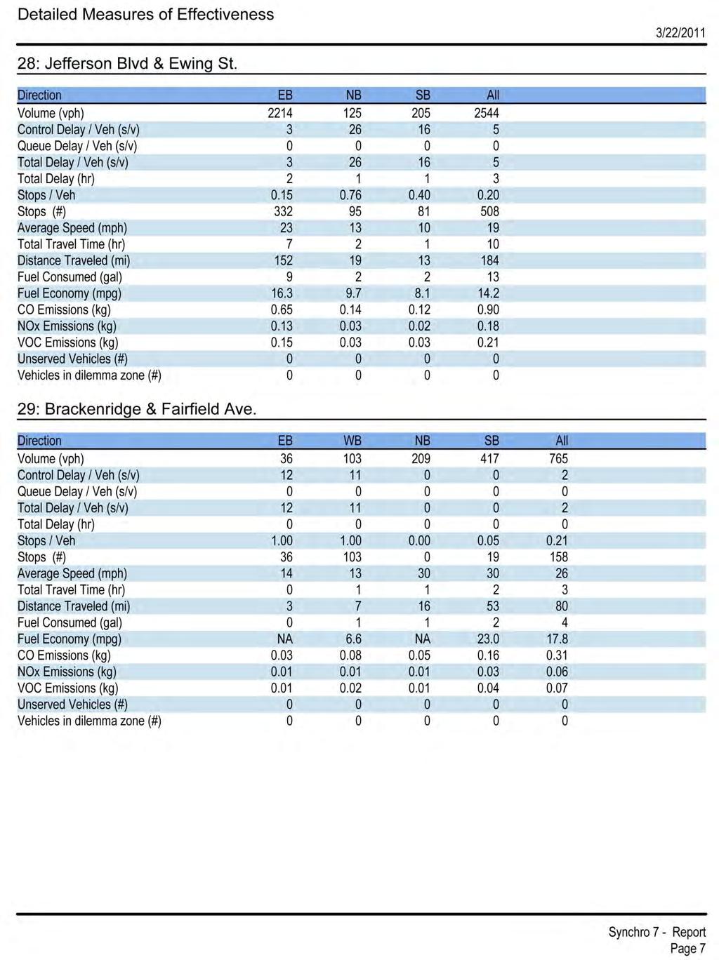
36 4.1. Network Analysis In order to analyze the effects of the changes proposed for the network, several software packages were utilized. For modeling traffic scenarios, Synchro and SIDRA were used, while AutoCAD Civil 3D was utilized to create the geometric design of the network Synchro Trafficware Synchro 7 was used to design the necessary network for the 20 year horizon. Synchro has many useful features such as multiple bitmaps for backgrounds, lane alignment through intersections, detailed detector settings, level of service analysis, and many more. These tools were applied to the design the five conceptual designs. Once all of the necessary values are inputted and the design is finalized, the option to optimize the network or separate intersections is considered. Optimizing the network will find the most efficient cycle length, for the whole network, and distribute the timing accordingly to approach volume counts. Figure 8 shows a typical intersection model in Synchro. Figure 8 Modeling with Synchro 7 After inputting the appropriate alterations for each of the alternatives, Synchro has the ability to generate a report detailing key performance measures in the network. A complete Synchro generated report can be seen in Appendix 8.1. While Synchro 35
37 analyzes many different items, seven primary entries were selected to verify the best alternative. The key elements selected to evaluate the alternatives were: total delay, stops per vehicle, fuel economy, average speedway, carbon monoxide emissions, and performance index. Table 2 displays the results for the main arterials traversing northbound and southbound through the network. By examining these results, the alternative which allows motorist to travel completely through the network most efficiently can be determined. The total results reveal Alternative #3b scoring the best overall in these performance areas. By summing the results of the two roadway results, the chosen design, Alternative #2a scored with second base overall, based solely on these performance measures. Table 2 Main Arterials Analysis based on Synchro Analysis Ewing Street Fairfield Avenue Alternative 1 2a 2b 3a 3b 1 2a 2b 3a 3b Total Delay (sec/veh) Stops/Vehicle Fuel Economy (mpg) Average Speed (mph) CO Emissions (kg) Performance Index Rank While determining the most efficient alternative for traversing completing north or sound through the entire network, equally important is how efficient road users can travel through all roads in the network, including those individuals traveling eastbound and westbound. Table 3 exhibits the results of the seven primary performance criterions. The complete network analysis again shows Alternative #3a with the highest ranking and Alternative #2a graded as the second highest. Table 3 - Synchro Analysis on Complete Network Network Totals Alternative 1 2a 2b 3a 3b Total Delay (sec/veh) Stops/Vehicle Fuel Economy (mpg) Average Speed (mph) CO Emissions (kg) Performance Index Rank

38 In order to verify there were not any major conflicts, the networks were monitored using the software associated with Synchro, called SimTraffic. SimTraffic simulates traffic on the roads and allows users to visualize how the network will respond to alterations. In addition to helping visualize the changes, SimTraffic also notifies the user of any potential problems that may be encountered. Specifically, when signal timings may need adjusted to allow adequate time for pedestrians to cross the intersection, or when a lagging phase may be more appropriate for a certain phase. An example of SimTraffic is shown in Figure 9. Figure 9 - SimTraffic Simulation SIDRA While Synchro is one of the premier macroscopic modeling programs for traditional intersections, when modeling a roundabout, Synchro has very limited capabilities. Therefore, SIDRA became the chosen program to model the proposed roundabout at the intersection on Wells Street and Superior Street. SIDRA has been in development for 37

39 over thirty years and includes fully updated analysis based on the most resent version of the Highway Capacity Manual. The first step in modeling a roundabout in SIDRA is laying out the geometry of the roadways. Once the geometric features are established, other parameters such as the expected traffic volumes during the peak hours can be applied to the model. Figure 10 displays roundabout model generated with SIDRA. The current configuration of Wells Street and Superior Street allowed for four lanes to be used on the north, west, and east sides of the roundabout with major additions to the roadway. Also, the current three lane configuration of Fairfield Avenue and Ewing Street was retained in the network. Figure 10 - Roundabout Modeling using SIDRA After finalizing the geometric features of the roundabout and entering the projected traffic volumes, SIDRA was able to determine the expected delay for each approach 38
40 during the peak hours. Four out of the five approach delays were under the project goal of 55 seconds. The SIDRA analysis confirmed a one lane roundabout with dedicated right hand turn lanes at three of the approaches would be sufficient for this particular intersection. The results of the SIDRA analysis are shown in Figure 11. Figure 11 - Roundabout Approach Delays based on SIDRA Analysis ArcGIS After each reported crash, police officers enter information into a form which is compiled into a statewide database. Using the database for the Fort Wayne area, problematic intersections in the network were identified. Each crash record in the database contains: latitude and longitude, vehicles involved, injuries, deaths, weather conditions, estimated damage, and several other factors which may have contributed to the accident. 39

41 Using the software program ArcGIS, the crashes were geocoded, displaying them in the aerial photo shown in Figure 12. Once the crashes were visible on the map, potentially problematic intersections were identified using the Identify tool. By selecting each individual point on the map, all there crashes that occurred at that particular point are displayed. Figure 12 - Geocoded Crash Data When zoomed into a particular intersection such as Superior Street and Wells Street shown in Figure 13, it appears only four crashes occurred in a three year period, but actually over twenty accidents ensued in this particular intersection. As previously mentioned, many accdients are represented by each point on the map, and the Identify tool must be used to detect all the the crashes. 40

42 Figure 13 - Geocoded Crash Data at Superior Street & Wells Street After analyzing the geocoded crashes, it became apparent the intersections with the highest crash rates were Superior Street and Wells Street, Fairfield Avenue and Main Street, and Ewing Street and Main Street. In order to determine the extent of the problem at each intersection, the following data was retrieved from the crash database: vehicles involved, number of individuals injured, deaths, and estimated damage. Tables 2-4 display the values corresponding to those particular intersections in each of the three years recorded in the database. Table 4 - Crash Analysis at Fairfield Avenue & Main Street Fairfield Avenue & Main Street Year Crashes Vehicles Involved # Injured Deaths Estimated Damage $130, $130, $52, Total $312,
43 Table 5 - Crash Analysis at Ewing Street & Main Street Ewing Street & Main Street Year Crashes Vehicles Involved # Injured Deaths Estimated Damage $106, $80, $120, Total $307, Table 6 - Crash Analysis at Superior Street & Wells Street Superior Street & Wells Street Year Crashes Vehicles Involved # Injured Deaths Estimated Damage $50, $20, $58, Total $129, From the compiled data for the three problematic intersections, it became apparent the most accidents with greatest numbers injuries were occurring on Main Street. Both intersections in the network on Main Street tallied over $300,000 in damages, which indicated a possible configuration change. In order to justify any changes, accidents per million entering vehicles (RMEV) was calculated with the equation shown below. Typically, RMEV values less than 2.0 are acceptable and do not require any alterations. The total RMEV for each of the three intersections is shown in Table 7. Table 7 - Crash Frequency Analysis Intersection Crashes Per Year ADT RMEV Superior Street & Wells Street Main Street & Ewing Street Main Street & Fairfield Avenue
44 The RMEV values for the three intersections fell below the critical value of 2.0, indicating a major change was not necessary. Even though there were not major issues with the intersections on Main Street were approaching a dangerous level. Therefore, the current four-lane design on Main Street will be converted to a three-lane design with a dedicated left turn in each direction. The left turn movements will also be given a protected left turn providing a safer movement for those users Detailed Plans Geometric Design AutoCAD Civil 3D is a powerful and efficient software program for civil engineers because it simplifies certain tasks that normal AutoCAD cannot, such as making alignments and creating intersections. This project took advantage of AutoCAD Civil 3D s features of creating alignments and designing a single lane roundabout based on AASHTO standards. The first step in creating the roundabout involved using a preexisting tutorial file that already had a surface layer for which the roundabout may be constructed on. Then an alignment for each roadway at the intersection was created using the AutoCAD s built in AASHTO standards with a ± 2% super elevation for drainage. From this point it is possible to use AutoCAD s create roundabout feature. By following the AutoCAD s tutorial, the intersection was created (see Geometric Design, Details for input data), though it had a few flaws. The approach lane on E. Superior Street was not created, but AutoCAD had a built in feature to allow for adding additional approach lanes. The next part was to determine how to handle the exiting number of lanes at each approach of the roundabout in order to be efficient and help with vehicular delay. It was decided that the option to add right turn slip lane would be the best choice. AutoCAD Civil 3D again provides necessary tools to add turn slip lanes. Following the tutorial and using basic AutoCAD tools for modification such as offset, copy, delete, and so on, turn slip lanes were added to W. Superior, E. Superior, Wells, and Ewing Street. A right turn slip lane was not added to Fairfield as this would need the addition of another lane and would likely not benefit that approach. Wells Street was converted from a 6-lane approach to a 4-land approach in order to work effectively with the single lane roundabout. The last section of the design is placing the signage in the correct location. AutoCAD Civil 3D provides a set of default signs that are to be used with recommended distances. These signs follow the MUTCD and IDM requirements. Some of the signs on the drawing, such as the pedestrians cross walk and the yield signs, exist in AutoCAD Civil 3D by default, but have been modified in order to follow the requirements of this project. 43

45 Figure 14 - General Layout of AutoCAD Design 44
46 Roundabout Definitions 1) Approach Design Speed - The design speed of the roadway leading into the roundabout. 2) Bypass Lane - A lane that separates right-turn movements from the roundaboutcirculating traffic. 3) Central Island - The area of the roundabout inside the circulatory roadway including the truck apron. 4) Central-Island Diameter - The diameter of the central island, including the truck apron. 5) Circulatory Lane - A lane used by vehicles circulating in the roundabout. 6) Circulatory Roadway - The travel lanes adjacent to the central island and outside the truck apron, including the entire circumference of the circle. 7) Circulatory-Roadway Width - The width between the outer edge of the inscribed diameter at the curb face of this roadway and the central island curb face. It is typically 1 to 1.2 times the width of the widest entry width. It does not include the width of a traversable apron, which is defined to be part of the central island. The circulatory roadway width defines the roadway width, curb face to curb face, for vehicle circulation around the central island. 8) Conflict Point - A point where traffic streams cross, merge, or diverge. 9) Deflection - The change in the path of a vehicle imposed by the geometric features of a roundabout, resulting in a slowing of vehicles. 10) Entry Angle - The angle between the entry roadway and the circulating roadway, measured at the yield line. 11) Entry Lane - The lane or set of lanes for traffic approaching the roundabout. 12) Entry Radius - The radius of curvature of the outside curb face at the exit. 13) Entry Width - The width of the roadway where it enters the roundabout. It is measured perpendicularly from the outside curb face to the inside curb face at the splitter-island point nearest the inscribed circle. 14) Exit Lane - The lane or set of lanes for traffic leaving the roundabout. 15) Exit Radius - The radius of curvature of the outside curb at the exit. 16) Exit Width - This defines the width of the exit where it meets the inscribed circle. It is measured perpendicularly from the right curb-face edge of the exit to the intersection point of the left curb-face edge and the inscribed circle. 17) Fastest Path - The shortest possible route that a single vehicle can travel through a roundabout in the absence of other traffic, and ignoring all lane markings. The fastest path determines the fastest possible entering, exiting, and circulating speeds within a roundabout. 18) Flare Length - The distance over which the approach roadway widens to the entry width, if such flaring is present. 45
47 19) Half Width, V - The width of the existing approach roadway before it starts to widen, if flaring is present. 20) Inscribed Circle - The outer edge of the circulatory roadway. 21) Inscribed-Circle Diameter - The outside diameter of the inscribed circle measured from face of curb to face of curb. 22) Landscaping Buffer - Often provided to separate vehicular and pedestrian traffic and to encourage pedestrians to cross only at the designated crossing locations. A landscaping buffer can also improve the aesthetics of the intersection. 23) Natural Vehicle Path - The path that a driver will navigate a vehicle given the layout of the intersection and the ultimate destination. 24) Path Overlap - This occurs where the natural path of a vehicle traveling through a roundabout overlaps the path of an adjacent vehicle. 25) Pedestrian Crossing - This is typically located about 10 ft before the yield line and is usually a painted crosswalk. A pedestrian crossing allows a pedestrian to cross in one direction of vehicle travel at a time and provides median refuge in the splitter island. 26) Roundabout - A circular at-grade intersection with yield control of all entering traffic, channelized approaches with raised splitter islands, counterclockwise circulation, and appropriate geometric curvature. 27) Splitter Island - The raised island at each two-way leg between entering and exiting vehicles, designed primarily to control entry and exit speeds by providing deflection. It also prevents wrong-way movements and provides pedestrian refuge. 28) Truck Apron - The paved portion of the central island located adjacent to the circulating roadway. It is defined by a sloping curb on the outside and helps accommodate large trucks. 29) Yield-at-Entry - The requirement that vehicles on all entry lanes must yield to vehicles within the circulatory roadway. 30) Yield Line - A pavement marking used to mark the point of entry from an approach into the circulatory roadway and is marked along the inscribed circle Geometric Components The geometric design of a roundabout is much different than that of a traditional intersection. Safety is still the main focus as always, but the way in which safety is obtained is drastically different. To obtain this safety in roundabouts, the most critical design aspect is to determine the appropriate vehicular speed through the roundabout. In order to determine the best speed in a roundabout one must find the fastest path allowed by the geometry of the roundabout. This speed will be determined by the alignment of 46
48 the roundabout and also the smallest radius (usually inscribed circle) within the fastest allowable path. According to the FHWA, the roundabout is optimally located when the centerlines of all approach legs pass through the center of the inscribed circle. If this is not possible, a slight offset to the left of the inscribed circle is acceptable. Figure 15 - Acceptable, Preferred, and Unacceptable Alignments The purpose of these alignments is to slow the entry and exit of vehicles entering and leaving the roundabout. To sharp of a tangential entry (as seen in Figure 14) will not slow a vehicle down enough to allow safe passage to other vehicles and pedestrians. If possible, it would be preferred that all entries are equally spaces apart (i.e. 3 entries 120 degrees apart, 4 entries 90 degrees apart). The design chosen for this project will be difficult to have all legs entering in the preferred radial alignment since there are five incoming approaches. Four of the five legs will have radial alignment with Wells Street being the only leg with a slight right offset alignment. This configuration is acceptable as the island diameter will be large enough to counteract this alignment problem, forcing vehicles to slow down to a safe speed. 47
49 Figure 16 - Fastest Path for Single Lane Urban Roundabout The next step is to calculate the design speed using the equation given by the Federal Highway Administration: where, V= velocity, R = smallest radius of through path, e = super elevation, f = side friction factor. The super elevation is usually assumed to be and for entry and exit curves respectively. According to the Indiana design guide the roundabout speed is determined by the fastest path allowed by the geometry of the roundabout. This is the smoothest, flattest path possible for a single vehicle, in the absence of other traffic and ignoring all lane markings, traversing through the entry, around the central island, and out the exit. Thus, the fastest path and design speed was found after inputting the given alignments and dimensions of the roundabout using AutoCAD Civil 3D. Figure 16 shows fastest path for which the design velocity will be found given an arbitrary roundabout. The first area to look at of the geometric elements in a roundabout is the inscribed circle diameter. The inscribed circle diameter is determined by many different design objectives and often times the designer must experiment with different diameters in order to find the optimal size. The FHWA actually supplies a range of given inscribed circle diameters based on whether the location of the roundabout is urban or rural, single lane or 48
50 double lane. Table 8 shows the recommended inscribed circle diameter range for a roundabout depending on the number of circulatory lanes and location. Table 8 - Recommended Values for Inscribed Circle Diameter Given by the FHWA Site Category Typical Design Vehicles Inscribed Circle Diameter Range (ft) Mini-Roundabout Single-Unit Truck Urban Compact Single-Unit Truck/Bus Urban Single Lane WB-15 (WB-50) Urban Double Lane WB-15 (WB-50) Rural Single Lane WB-20 (WB-67) Rural Double Lane WB-15 (WB-50) The design vehicle is the largest vehicle the roundabout is expected to handle safely. For example, a WB-50 would be a semi-truck with a 50 foot trailer attached. After using SIDRA and Synchro it was determined that a single lane urban roundabout would be the best choice for the given network. The roundabout design at the intersection of Wells and Superior will be expected to handle vehicles as large as WB-67. Since the single lane roundabout will need to be designed to handle a slightly larger vehicle, the inscribed circular diameter chosen was 130 feet in order to handle the larger vehicle while taking up as little right-of-way as possible. This inscribed circle will include the lane width, truck apron, and the center island. The lane width needs to have necessary space in order to accommodate for the design vehicle, in this case a WB-65. According to the FHWA roundabout guide, the lane width should be at least as wide as the maximum entry width (up to 120% of the maximum entry width). Therefore, the lane width was chosen to be equal to the maximum entry width of the roundabout design, 20 feet. The truck apron is a raised portion on pavement on the outer edge of the central island. Note: the truck apron is technically part of the central island, but for design parameters it was chosen to explain them as separate entities. This portion of pavement acts as an extra lane for large vehicles by allowing the back wheels of the truck to ride up on the truck apron so the truck can complete its turn easily and safely. The raised section of pavement will discourage smaller vehicles from using this truck apron. It is recommended that the truck apron be between 3 and 13 feet. For this design, a truck apron of 10 feet was chosen. The last section of the inscribed circle is the central island. The central island is in most inner part of the roundabout and should always be raised from the ground so that drivers will be able to easily recognize. The central island plays a vital role in determining how much vehicles will be deflected as they travel through the roundabout. This portion will encompass the remaining space inside the inscribed circle diameter, 70 feet. The next step added the addition of a turn slip lane for right turning movements only. This was done in order to conform better to the existing roadway conditions and improve delay times without adding a second lane to the roundabout. The only approach that did 49

51 not receive a right turn slip lane was Fairfield Street since the existing three-lane geometry of the roadway would not allow this addition. The next part of the design will be to determine the entry and exit widths. Entry widths play a vital role in the capacity and safety of a roundabout. Entry widths need to be kept at a minimum to maximize safety (slowing vehicles down) while also being able to achieve the necessary capacity demand. According to the INDOT design guide, entry widths are to be measured perpendicularly from the outside curb face to the inside curb face at the splitter island point nearest to the inscribed circle. Entry widths are preferred to be narrow in order to increase safety; however, a WB-65 vehicle will require an 18 to 22 ft entry width. By increasing the entry width or flare length, the capacity of the roundabout will greatly increase. For this design, an entry width of feet was chosen in order to balance the need for capacity and safety while also being able to support a WB-65 trailer. Exit widths need to be at least the same size as the circulatory width, 20 feet. In order to determine the radii of the entry and exit curves, AutoCAD Civil 3D was used. AutoCAD allowed each entry and exit curve to be optimally designed using the existing alignments and AutoCAD s built in AASHTO Design Standards. The entry curve controls, in part, the amount of deflection imposed on vehicles entering the roundabout, thus decreasing or increasing the speed of the vehicle. The FHWA recommends the entry radii to be between 33 to 98 feet for a single lane urban roundabout. Figure 17 - Example of Entry Width and Entry Radii 50


52 Exits usually have larger radii to help minimize congestion of those vehicles exiting while at the same time making sure the radius is small enough to maintain low speeds for pedestrians who may be crossing. Like the entry radii, AutoCAD determined the best radii for the existing aliment of the roadway for the exit radii. According to the FWHA design guide, exit radii should be no less than 50 feet unless the intersection has a lot of pedestrian activity. In that case the exit radii may be as low as 33 to 39 feet. For this design AutoCAD chose the best radii for the exit on each leg based on the given alignments and the chosen inscribed circle diameter. Figure 18 below shows the exit radii on East Superior Street. Figure 18 - Description of Exit Radii The effective flare length for an approach may be from 15 feet to as long as 330 feet, see Figure 18. According to the INDOT design guide, after the effective flare length exceeds 330 feet, its impact on capacity will become minimal. Using AutoCAD, it was determined that the best flare length for the given roadway alignment would be around 140 feet for each leg. 51

53 Figure 19 - Dimensions of General Flare Length The next section to be considered is for pedestrians and the splitter islands. Pedestrian safety and pedestrian convenience is very important in the design of roundabout where pedestrians are present. At the intersection of Superior Street and Wells Street there will be a steady amount of pedestrian traffic, so this was taken into account in the design of the roundabout. In order to account for pedestrian convenience and pedestrian safety it is important to make the crosswalks as close to the intersection as possible without putting the pedestrian in danger. The reason for this is that pedestrians will normally find the quickest path and if the crosswalk is inconvenient the pedestrian may look for a shorter path and put themselves and vehicles in danger. One way to help keep the pedestrian crosswalk close to the intersection, while keep the pedestrian safe, is to have a splitter island that is easily accessible. The splitter island actually has multiple functions. It not only makes a safe haven for pedestrians crossing traffic, but also helps guide traffic into the roundabout and separate opposing flows of traffic. The splinter island can also be used as a place for mounting signs. According the FHWA design guide, the pedestrian refuge space provided by the splinter island should be a minimum width of 6 feet in order to adequately provide shelter for persons pushing a stroller or using a bicycle. The design manual also states that the pedestrian crossing should be located feet away from the yield line. 52

54 Figure 20 - Dimensions of Splitter Island Other Changes to Existing Roadway The following section will discuss changes that were made to the existing roadway with regards to the chosen design alternative. This design alternative includes changing Fairfield, Ewing, & Brackenridge Street to 2-way streets as opposed to the current 1-way conditions. There will also be a 2-way turn lane added to the center lane on Fairfield and Ewing Street. Lastly, the lane configuration on Main Street will also be changed from a 4-lane 2-way road to a 3-lane 2-way road with dedicated right hand turns. Because there will be no change to the actual roadway geometry the ease of converting the 1-way roads to 2-way with a 2-way center turn lane will be fairly easy since Fairfield and Ewing currently have three lanes in one direction. This means that using the current roadway it will be possible to change the 1-way traffic to 2-way traffic with a center turn lane by changing the striping on the road, as well as the addition of signal lights and changing the signal timings. This striping will of course follow the guidelines specified in the MUTCD. The lane widths will stay at the current lane widths of 12ft. Brackenridge Street is currently a single lane 1-way road with public parking on both sides of the street. The southern parking lots will be kept while the northern parking lots will be converted into a driving lane in order to make Brackenridge a 2-way street. Brackenridge will also keep the lane widths at 12ft in order to keep the existing geometry. The only addition to the changes made at Brackenridge will be a stop sign at the intersection of Brackenridge and Fairfield in accordance to the MUTCD. 53


55 Figure 21 - Current Geometric Conditions on Brackenridge Street Figure 22 - Future Geometric Conditions on Brackenridge Street Concerning the changes made to the signalized intersections on Fairfield and Ewing Street, there will be a dedicated left hand turn installed at all approaches as well as new signal lights for the new approaches. The dedicated left hand turns will also be 12ft in order to stay with the geometric constraints. Since the lane configurations and traffic volumes will be changing, the signal timings will also be changing. Using Synchro, 54

56 optimized signal timings were obtained and may be found in the appendix for more details. The changes made to Main Street will also follow a similar concept as the changes made on Fairfield, Ewing, and Brackenridge. In order to improve safety and traffic delay, it has been found that changing Main Street to a 3-lane 2-way road with dedicated right hand turns would be the best option. The lane configurations will be changed by changing the paint markings and signals to coincide with the new lane configuration in accordance with the MUTCD. The three lanes will stay at the standard width of 12ft. This will add extra space on the edges of Main Street since there will be one less lane. The extra space may be turned into more parking spaces, extra sidewalk room, or even a bicycle lane. Currently, it has not been fully determined what to do with this extra space. Having a meeting with the public and surrounding businesses is likely the best option for determining the most important social use of the extra lane space. Figure 23 - Current Geometric Conditions on Main Street and Fairfield 55

57 Figure 24 - Future Geometric Conditions on Main Street and Fairfield 56
58 5. Section V: Cost Analysis/Estimation 57
59 5.1. Construction Based on past experience, roundabout construction typically last less than twelve weeks. During construction of the roundabout, any one roadway will not be completely closed for any more than a four week period. One side of the roundabout will be constructed during an approximate four week period, and traffic will be redirected to opposite of the intersection. Once one side the roundabout is complete, traffic will then be rerouted to the completed side of the roundabout. Along with the construction of the roundabout, alterations must be made to the north and southbound roads of Fairfield Avenue and Ewing Street. Those modifications include: removing and replacing roadway markings, adding additional signage, and adding and adjusting traffic signal Cost Estimation To estimate the cost of the materials for the project, the current unit prices utilized by the Indiana Department of Transportation were taken into account. The total material list and costs are shown in Table 9. Not included in the cost estimation are the engineering, right-of-way, and labor cost. These items could add substantial value to the project, but were not considered in our cost estimate. 58
60 Table 9 Materials Costs Item Unit Quantity Unit Cost($) Cost ($) Asphalt TON $ $353, Concrete CYS $ $32, Sidewalk Concrete, 6 in. SYS 144 $43.04 $6, Signs Each 27 $22.75 $ Sign Post, Tubular LFT 182 $57.50 $10, Loop Detector Each 10 $ $9, Traffic Signal Head, 3 Face, 12 in. Red, Each 10 $ $6, Amber Arrow, Green Arrow Fiber Optic Cable, In Conduit LFT 750 $3.00 $2, Mast Arm, 15 ft. Each 10 $ $5, Light Standard Each 4 $ $3, Light Pole, 42 ft. E.M.H., 15 ft. Mast Arm Each 4 $1, $5, Lighting Foundation, Concrete, High Mast Each 4 $4, $18, Tower Pavement Message Markings, Preformed LFT 144 $ $28, Plastic, Arrow Transverse Marking, Thermoplastic, LFT 616 $1.23 $ Crosswalk, 8 in. Line, Thermoplastic, Broken, White, 4 in. LFT 750 $0.32 $ Line, Thermoplastic, Solid, White, 4 in. LFT 1000 $0.28 $ Pavement Message Markings, Thermoplastic, Each 5 $ $ Word (Yield) Line, Thermoplastic, Broken, Yellow, 4 in. LFT $0.22 $4, Line, Thermoplastic, Solid, Yellow, 4 in. LFT $0.27 $6, Transverse Marking, Thermoplastic, Stop Line, 24, in. Pavement Message Markings, Thermoplastic, Word (Only) Pavement Message Markings, Thermoplastic, Word (Stop) LFT 112 $4.22 $ Each 23 $75.38 $1, Each 8 $67.00 $ Total $465, CYS: cubic yards LFT: linear foot SYS: square yards 59
61 6. Conclusion 60
62 For the downtown roadway network of Fairfield Avenue and Ewing Street bounded by Superior Street on the north and Baker Street on the south, several modifications will aid the City of Fort Wayne in improving mobility to key areas in the downtown region and accessibility through the network. Keeping level of service, accessibility, mobility, cost, safety, environmental impact, and public acceptance in mind, some of the modifications include the implementation of: Two-Way Travel on Fairfield Avenue, Ewing Street, and Brackenridge Street Two-way left turn lanes on Fairfield Avenue and Ewing Street Converting Main Street from four lanes to a three lanes with dedicated left turn lanes Dedicated left-hand turns at all signalized intersections A single lane roundabout at the intersection of Superior Street, Fairfield Avenue, and Ewing Street By making these adjustments to the network, the downtown area will become more attractive to developers and businesses owners, while maintaining satisfactory vehicular flow and circulation for the 20-year horizon. 61
63 7. References 62
64 "MUTCD 2009 Edition- FHWA MUTCD." Manual on Uniform Traffic Control Devices (MUTCD) - FHWA. Dec Web. 1 Apr < NCUTCD - National Committee on Uniform Traffic Control Devices. Web. 10 Apr < "NYSDOT Roundabout Design Guidance" New York Department of Transportation. Web. 5 Apr < Roess, Roger P., Elena S. Prassas, and William R. McShane. Traffic Engineering. Boston: Pearson, Print. "Roundabout Design Standards." City of Colorado Springs Transportation Engineering (2005): Oct Web. 5 Apr < pdf>. "Roundabouts - FHWA Safety Program." Home - FHWA Safety Program. Feb Web. 10 Feb < "The Indiana Design Manual." IN.gov: Home. 21 Jan Web. 18 Mar < Transportation Planning Handbook. 3rd ed. Washington, DC: Institute of Transportation Engineers, Print. 63
65 8. Appendix 64
66 8.1. Sample Synchro Network Analysis for Alternative #2a. 65
67 66
68 67
69 68
70 69
71 70
72 71
Project Report. South Kirkwood Road Traffic Study. Meadows Place, TX October 9, 2015
 Meadows Place, TX October 9, 2015 Contents 1 Introduction... 1 2 Data Collection... 1 3 Existing Roadway Network... 2 4 Traffic Volume Development... 2 5 Warrant Analysis... 3 6 Traffic Control Alternative
ROUNDABOUTS/TRAFFIC CIRCLES
 GENERAL 1. Description This standard identifies minimum requirements that shall be met for Roundabouts and Neighborhood Traffic Circles in the design and construction of elements for Arlington County Horizontal
133 rd Street and 132 nd /Hemlock Street 132 nd Street and Foster Street MINI ROUNDABOUTS. Overland Park, Kansas
 133 rd Street and 132 nd /Hemlock Street 132 nd Street and Foster Street MINI ROUNDABOUTS Overland Park, Kansas September 1, 2017 TABLE OF CONTENTS 1. INTRODUCTION... 1 2. LITERATURE REVIEW... 1 3. CONCEPT
Existing Conditions. Date: April 16 th, Dan Holderness; Coralville City Engineer Scott Larson; Coralville Assistant City Engineer
 Date: April 16 th, 2015 To: From: Re: Dan Holderness; Coralville City Engineer Scott Larson; Coralville Assistant City Engineer Darian Nagle-Gamm, Traffic Engineering Planner Highway 6 (2 nd Street) /
Roundabout Design Aid PREPARED BY TRAFFIC AND SAFETY
 Roundabout Design Aid PREPARED BY TRAFFIC AND SAFETY May 2018 Engineering Manual Preamble This manual provides guidance to administrative, engineering, and technical staff. Engineering practice requires
Roundabout Prequalification Training. March 11, 2015
 Roundabout Prequalification Training March 11, 2015 Presenters American Structurepoint, Inc. Jeromy Grenard, PE, PTOE Craig Parks, PE Why Roundabouts? Everybody else is building them? They look cool? Circles
City of Albert Lea Policy and Procedure Manual 4.10 ALBERT LEA CROSSWALK POLICY
 4.10 ALBERT LEA CROSSWALK POLICY PURPOSE: Pedestrian crosswalks are an integral part of our transportation infrastructure. To be effective and promote safety, marked crosswalks must be installed after
Update to DOTD Roundabout Design Policy
 Update to DOTD Roundabout Design Policy Roundabout In Louisiana Louisiana has 18 roundabouts in operation and 53 proposed History EDSM s or Engineering Directives and Standards set DOTD policies, procedures,
Intersection Improvement: Sturgeon Road, Silver Avenue and Murray Park Road Roundabout. Welcome. Public Information Session
 Intersection Improvement: 1 Welcome WHY IS AN INTERSECTION IMPROVEMENT NEEDED? 2 Traffic volumes for Sturgeon Road, Silver Avenue and Murray Park Road exceed the capacity of the existing 4-way stop controlled
Modern Roundabouts: a guide for application
 Modern Roundabouts: a guide for application Kentucky Community Transportation Innovation Academy 2005 The contents of this booklet reflect the views of the authors who are responsible for the facts and
Introduction Roundabouts are an increasingly popular alternative to traffic signals for intersection control in the United States. Roundabouts have a
 HIGH-CAPACITY ROUNDABOUT INTERSECTION ANALYSIS: GOING AROUND IN CIRCLES David Stanek, PE and Ronald T. Milam, AICP Abstract. Roundabouts have become increasingly popular in recent years as an innovative
TRAFFIC IMPACT ANALYSIS
 TRAFFIC IMPACT ANALYSIS FOR THE CHAMPAIGN UNIT#4 SCHOOL DISTRICT PROPOSED HIGH SCHOOL (SPALDING PARK SITE) IN THE CITY OF CHAMPAIGN Final Report Champaign Urbana Urbanized Area Transportation Study 6/24/2014
TRANSPORTATION ANALYSIS REPORT US Route 6 Huron, Erie County, Ohio
 TRANSPORTATION ANALYSIS REPORT US Route 6 Huron, Erie County, Ohio December 12, 2012 Prepared for: The City of Huron 417 Main Huron, OH 44839 Providing Practical Experience Technical Excellence and Client
Glenn Avenue Corridor Traffic Operational Evaluation
 Glenn Avenue Corridor Traffic Operational Evaluation PREPARED FOR: THE CITY OF AUBURN PREPARED BY: DECEMBER 2007 Glenn Avenue Corridor Study--Auburn, Alabama TABLE OF CONTENTS Introduction... 1 Background
Small Area Study U.S. Route 220 and VA Route 615 Intersection. Bath County, Virginia
 Small Area Study U.S. Route 220 and VA Route 615 Intersection Bath County, Virginia Prepared by the Central Shenandoah Planning District Commission Final Report February 2018 Table of Contents 1. INTRODUCTION...
Roundabout Design Principles
 des Carrefours Giratoires Roundabout Design Principles NCLUG Roundabout Luncheon Tuesday, March 4, 2014 Prepared by: des Carrefours Agenda Giratoires Roundabout design process: Planning and Policy Lane
TRAFFIC STUDY GUIDELINES Clarksville Street Department
 TRAFFIC STUDY GUIDELINES Clarksville Street Department 9/1/2009 Introduction Traffic studies are used to help the city determine potential impacts to the operation of the surrounding roadway network. Two
Appendix A: Crosswalk Policy
 Appendix A: Crosswalk Policy Appendix A: Crosswalk Policy Introduction This citywide Crosswalk Policy is aimed at improving pedestrian safety and enhancing pedestrian mobility by providing a framework
ALLEY 24 TRAFFIC STUDY
 ALLEY 24 TRAFFIC STUDY in City of Frostburg, Maryland January 2013 3566 Teays Valley Road Hurricane, WV Office: (304) 397-5508 www.denniscorporation.com Alley 24 Traffic Study January 2013 Frostburg, Maryland
Traffic Impact Analysis Chatham County Grocery Chatham County, NC
 Chatham County Grocery Chatham County, NC TABLE OF CONTENTS 1. INTRODUCTION... 1 1.1. Location and Study Area... 1 1.2. Proposed Land Use and Access... 2 1.3. Adjacent Land Uses... 2 1.4. Existing ways...
Access Management in the Vicinity of Intersections
 Access Management in the Vicinity of Intersections FHWA-SA-10-002 Technical Summary Photo: Ralph Bentley (used with permission) 0 Access Management is: The design, implementation and management of entry
A plan for improved motor vehicle access on Railroad Avenue in Provincetown
 A plan for improved motor vehicle access on Railroad Avenue in Provincetown February 2011 A plan for improved motor vehicle access on Railroad Avenue in Provincetown INTRODUCTION AND PROBLEM IDENTIFICATION
BLOSSOM AT PICKENS SIGNALIZED INTERSECTION IMPROVEMENT STUDY
 BLOSSOM AT PICKENS SIGNALIZED INTERSECTION IMPROVEMENT STUDY Class Project Report for ECIV 542 Traffic Engineering Submitted by Omor Sharif Muchun Song Narges Kaveshgar Quyen Pham Chih-Yao Lin Submission
Capital Region Council of Governments
 March 23, 2018 Capital Region Council of Governments PROJECT CONCEPT REPORT Realignment of Swamp and Northfield Road s approaches to Route 44 (Boston Turnpike) Town of Coventry SUMMARY: The Town of Coventry
List of Attachments. Location Map... Site Plan... City of Lake Elsinore Circulation Element... City of Lake Elsinore Roadway Cross-Sections...
 List of Attachments Exhibits Location Map... Site Plan... City of Lake Elsinore Circulation Element... City of Lake Elsinore Roadway Cross-Sections... Existing Lane Geometry and Traffic Controls... Existing
400 Intersection Design. Table of Contents. 401 Intersections At-Grade Two Way Left Turn Lanes (TWLTL)... 9
... 9") 4 Intersection Design Table of Contents 41 Intersections At-Grade... 1 41.1 Intersection Locations... 1 41.2 Intersection Traffic Control and Operational Analysis... 1 41.2.1 Signals... 1 41.2.2 Stop Control...
4 Intersection Design Table of Contents 41 Intersections At-Grade... 1 41.1 Intersection Locations... 1 41.2 Intersection Traffic Control and Operational Analysis... 1 41.2.1 Signals... 1 41.2.2 Stop Control...
Figure 1: Vicinity Map of the Study Area
 ARIZONA TEXAS NEW MEXICO OKLAHOMA May 5, 2016 Mr. Anthony Beach, P.E. BSP Engineers 4800 Lakewood Drive, Suite 4 Waco, Texas 76710 Re: Intersection and Access Analysis along Business 190 in Copperas Cove
METHODOLOGY. Signalized Intersection Average Control Delay (sec/veh)
") Chapter 5 Traffic Analysis 5.1 SUMMARY US /West 6 th Street assumes a unique role in the Lawrence Douglas County transportation system. This principal arterial street currently conveys commuter traffic
Chapter 5 Traffic Analysis 5.1 SUMMARY US /West 6 th Street assumes a unique role in the Lawrence Douglas County transportation system. This principal arterial street currently conveys commuter traffic
Intersection Traffic Control Feasibility Study
 Intersection Traffic Control Feasibility Study CSAH 9 at CSAH 60 (185th Avenue) Prepared For: Dakota County Transportation Department Western Service Center 14955 Galaxie Avenue, 3rd Floor Apple Valley,
Shockoe Bottom Preliminary Traffic and Parking Analysis
 Shockoe Bottom Preliminary Traffic and Parking Analysis Richmond, Virginia August 14, 2013 Prepared For City of Richmond Department of Public Works Prepared By 1001 Boulders Pkwy Suite 300, Richmond, VA
Traffic Impact Study WestBranch Residential Development Davidson, NC March 2016
 Traffic Impact Study WestBranch Residential Development Davidson, NC March 216 TRAFFIC IMPACT STUDY FOR THE WestBranch Residential Development LOCATED IN DAVIDSON, NC Prepared For: Lennar Carolinas, LLC
MEMORANDUM. Layout Of Study Intersections And Traffic Control
 BOSTON REGION METROPOLITAN PLANNING ORGANIZATION Richard A. Davey, MassDOT Secretary and CEO and MPO Chairman Karl H. Quackenbush, Executive Director, MPO Staff DATE November 15, 2012 TO FROM RE Town of
Traffic Impact Analysis Walton Acres at Riverwood Athletic Club Clayton, NC
 Traffic Impact Analysis Walton Acres at Riverwood Athletic Club Clayton, NC 1. TABLE OF CONTENTS INTRODUCTION...1 1.1. Site Location and Study Area...1 1.2. Proposed Land Use and Site Access...2 1.3.
CITY OF SARATOGA SPRINGS PEDESTRIAN CROSSING TOOLBOX
 CITY OF SARATOGA SPRINGS PEDESTRIAN CROSSING TOOLBOX This toolbox is to be used to guide pedestrian crossing improvements within the City of Saratoga Springs. Details for each crossing type are provided.
Traffic Impact Memorandum. May 22, 2018
 BISHOP PROFESSIONAL DEVELOPMENT BUILDING Proposed Land-use Change & Parking Modification 3601 SW 31st Street Topeka, Kansas 66614 CFS Project No. 185077 Traffic Impact Memorandum May 22, 2018 Prepared
Washington St. Corridor Study
 FIGURE 7.17 Bridge Alternatives - Cross Sections 86 Discarded Alternative: Short-Term Bridge Repair Short-term repairs and west bridge span replacement were considered during analysis. Short-term repairs
CITY OF LOS ANGELES INTER-DEPARTMENTAL MEMORANDUM
 CITY OF LOS ANGELES INTER-DEPARTMENTAL MEMORANDUM Date: April 1, 219 To: Honorable City Council c/o City Clerk, Room 395, City Hall Attention: Honorable Mike Bonin, Chair, Transportation Committee From:
DUNBOW ROAD FUNCTIONAL PLANNING
 DUNBOW ROAD FUNCTIONAL PLANNING Final Report August 3, 216 #31, 316 5th Avenue NE Calgary, AB T2A 6K4 Phone: 43.273.91 Fax: 43.273.344 wattconsultinggroup.com Dunbow Road Functional Planning Final Report
Simulation Analysis of Intersection Treatments for Cycle Tracks
 Abstract Simulation Analysis of Intersection Treatments for Cycle Tracks The increased use of cycle tracks also known as protected bike lanes has led to investigations of how to accommodate them at intersections.
DEPARTMENT OF ENVIRONMENTAL SERVICES. North Harrison Street (Lee Highway to Little Falls Road) Comparative Analysis. Prepared for:
 Comparative Analysis. Prepared for:") DEPARTMENT OF ENVIRONMENTAL SERVICES North Harrison Street (Lee Highway to Little Falls Road) Comparative Analysis Prepared for: Arlington County Department of Environmental Services 2100 Clarendon Boulevard,
DEPARTMENT OF ENVIRONMENTAL SERVICES North Harrison Street (Lee Highway to Little Falls Road) Comparative Analysis Prepared for: Arlington County Department of Environmental Services 2100 Clarendon Boulevard,
Access Management Regulations and Standards
 Access Management Regulations and Standards Efficient highway operation Reasonable property access Concept of Access Management The way to manage access to land development while simultaneously preserving
Traffic Impact Study. Westlake Elementary School Westlake, Ohio. TMS Engineers, Inc. June 5, 2017
 TMS Engineers, Inc. Traffic Impact Study Westlake Elementary School Westlake, Ohio June 5, 2017 Prepared for: Westlake City Schools - Board of Education 27200 Hilliard Boulevard Westlake, OH 44145 TRAFFIC
INTRODUCTION THOROUGHFARE SYSTEM CLASSIFICATIONS
 INTRODUCTION The thoroughfare plan will assist public officials in the development of a specialized system for efficient and safe movement of vehicular traffic while minimizing potential conflicts with
ORANGE COUNTY PUBLIC WORKS TRAFFIC INVESTIGATIONS
 ORANGE COUNTY PUBLIC WORKS TRAFFIC INVESTIGATIONS STAFF REPORT OF: January 6, 2019 SUPERVISORIAL DISTRICT: 5 SUBJECT: LOCATION: INVESTIGATOR: O Neill Drive at Roanoke Drive; Ladera Ranch; TB 922-E6 Clever
PEDESTRIAN ACCOMMODATIONS DPS 201 AT INTERCHANGES
 PEDESTRIAN ACCOMMODATIONS DPS 201 AT INTERCHANGES UNDERSTANDING THE ISSUES Intersections of freeway ramp terminals at crossroads are the most critical components of an interchange Challenge: balance mobility
TRAFFIC IMPACT STUDY And A TRAFFIC SIGNAL WARRANT ANALYSIS FOR A SENIOR LIVING AND APARTMENT DEVELOPMENT
 TRAFFIC IMPACT STUDY And A TRAFFIC SIGNAL WARRANT ANALYSIS FOR A SENIOR LIVING AND APARTMENT DEVELOPMENT DEERFIELD TOWNSHIP, WARREN COUNTY, OHIO Nantucket Circle and Montgomery Road () Prepared for: ODLE
SELECTED ROADWAY CAPACITY ANALYSIS
 CHAPTERFOUR SELECTED ROADWAY CAPACITY ANALYSIS 4.1 SELECTED ROADWAY CAPACITY ANALYSIS Introduction Capacity analysis was performed on six selected roadways within the Dearborn County study area using the
Southside Road. Prepared for: City of St. John s Police & Traffic Committee. Prepared by: City of St. John s Traffic Division
 Southside Road Prepared for: City of St. John s Police & Traffic Committee Prepared by: City of St. John s Traffic Division January 2007 Southside Road - Traffic Report Page 1 of 9 BACKGROUND: th At the
PEDESTRIAN ACCOMMODATIONS DPS 201 AT ROUNDABOUTS
 PEDESTRIAN ACCOMMODATIONS DPS 201 AT ROUNDABOUTS WHY THEY WORK FOR PEDESTRIANS IF DESIGNED CORRECTLY Separated sidewalks direct peds to crosswalks Splitter island Slow speed exit Truck apron Crosswalk
8 PROPOSED ROUNDABOUT DUFFERIN STREET AND KING VAUGHAN ROAD INTERSECTION CITY OF VAUGHAN
 8 PROPOSED ROUNDABOUT DUFFERIN STREET AND KING VAUGHAN ROAD INTERSECTION CITY OF VAUGHAN The Transportation Services Committee recommends the adoption of the recommendation contained in the following report
Evaluation of M-99 (Broad Street) Road Diet and Intersection Operational Investigation
 Road Diet and Intersection Operational Investigation") Evaluation of M-99 (Broad Street) Road Diet and Intersection Operational Investigation City of Hillsdale, Hillsdale County, Michigan June 16, 2016 Final Report Prepared for City of Hillsdale 97 North Broad
Evaluation of M-99 (Broad Street) Road Diet and Intersection Operational Investigation City of Hillsdale, Hillsdale County, Michigan June 16, 2016 Final Report Prepared for City of Hillsdale 97 North Broad
5.0 Roadway System Plan
 Southwest Boise Transportation Study Page 16 5.0 Roadway System Plan The Roadway System Plan outlines roadway improvements in the Initial Study Area. It forecasts future deficiencies on the arterial system,
TRAFFIC CALMING TOOLBOX. For the residents of the City of Decatur, Georgia
 TRAFFIC CALMING TOOLBOX For the residents of the City of Decatur, Georgia 2 City of Decatur Traffic Calming Toolbox Public Works Department 2635 Talley Street Decatur, GA 30030 404.377.5571 3 Welcome to
Summary: Mercer County Princeton Avenue & Spruce Street Study January 2009
 Summary: Several recent studies have assessed potential development and redevelopment opportunities in the Mercer Crossing area of Trenton, Ewing, and Lawrence. This Princeton Avenue and Spruce Street
Traffic Impact Study Little Egypt Road Development Denver, North Carolina June 2017
 Traffic Impact Study Little Egypt Road Development Denver, North arolina June 2017 N. Little Egypt Road DQ\ QDQFLQJ VDOHV RU RWKHU SHUIRUPDQFH EDVHG FULWHULD Proposed Site Driveways Site Driveway 1 TRAFFI
Abstract. Background. protected/permissive operation. Source: Google Streetview, Fairview/Orchard intersection
 ITE 2015 Western District Annual Meeting Ada County Highway District s Flashing Yellow Arrow Initiative Primary Author: Tim Curns, PE Ada County Highway District Traffic Engineer Author: Andrew Cibor,
400 Intersection Design
 400 Intersection Design Table of Contents 401 Intersections At-Grade... 4-1 401.1 Intersection Locations... 4-1 401.2 Intersection Traffic Control and Operational Analysis... 4-1 401.2.1 Signals. 4-1 401.2.2
5858 N COLLEGE, LLC N College Avenue Traffic Impact Study
 5858 N COLLEGE, LLC nue Traffic Impact Study August 22, 2016 Contents Traffic Impact Study Page Preparer Qualifications... 1 Introduction... 2 Existing Roadway Conditions... 5 Existing Traffic Conditions...
ENHANCED PARKWAY STUDY: PHASE 2 CONTINUOUS FLOW INTERSECTIONS. Final Report
 Preparedby: ENHANCED PARKWAY STUDY: PHASE 2 CONTINUOUS FLOW INTERSECTIONS Final Report Prepared for Maricopa County Department of Transportation Prepared by TABLE OF CONTENTS Page EXECUTIVE SUMMARY ES-1
180 Grand Avenue, Suite x117 Dowling Associates, Inc.
 180 Grand Avenue, Suite 250 510.839.1742 x117 Oakland, CA 94612 510.839.0871 fax www.dowlinginc.com mbowman@dowlinginc.com Dowling Associates, Inc. Date: Memorandum To: CC: From: Ms. Leah Greenblat City
Access Management Regulations and Standards for Minor Arterials, Collectors, Local Streets
 Access Management Regulations and Standards for Minor Arterials, Collectors, Local Streets September 2009 Paul Grasewicz Access Management Administrator Concept of Access Management The way to manage access
Frequently Asked Questions
 Frequently Asked Questions Business US 190 in Copperas Cove From Avenue D to Constitution Drive What is access management? A. Access Management is a growing effort by government agencies to improve how
Balancing Operation & Safety for Motorized and Non-Motorized Traffic
 Balancing Operation & Safety for Motorized and Non-Motorized Traffic Brian Willham, PE, PTOE Iowa Director - MOVITE June 30, 2014 Learning Objectives: When & Why should we measure the performance of complete
Traffic Signal Phasing Study Summary & Staff Recommendations
 Traffic Signal Phasing Study Summary & Staff Recommendations Consultant Study by Skipper Consulting, Inc. Staff Committee Recommendations by Randy Pewitt, Executive Director of Emergency Mgt. and Safety
Low Level Road Improvements Traffic Analysis. Report
 Low Level Road Improvements Traffic Analysis Report June, 22 Table of Contents. INTRODUCTION.... LOW LEVEL ROAD PROJECT....2 STUDY AREA....2. West-End Corridor Improvements... 2.2.2 East-End Corridor Improvements...
Highway 111 Corridor Study
 Highway 111 Corridor Study June, 2009 LINCOLN CO. HWY 111 CORRIDOR STUDY Draft Study Tea, South Dakota Prepared for City of Tea Sioux Falls Metropolitan Planning Organization Prepared by HDR Engineering,
ROUNDABOUTS. Improving Safety and Efficiency. SR83 & Smithville Western Rd. Joel Montgomery, PE Director of Administration
 ROUNDABOUTS Improving Safety and Efficiency SR83 & Smithville Western Rd. Joel Montgomery, PE Director of Administration The Ohio Department of Transportation District 3 906 North Clark Ave. Ashland, OH
Comments EXECUTIVE SUMMARY
 Comments 1. Under any Alternatives, MCDOT should provide better at-grade pedestrian crossing of Georgia Avenue and Forest Glen Road, including improved crosswalks with wider medians and adequate signal
Chapter 4 Traffic Analysis
 Chapter 4 Traffic Analysis PURPOSE The traffic analysis component of the K-68 Corridor Management Plan incorporates information on the existing transportation network, such as traffic volumes and intersection
M-58 HIGHWAY ACCESS MANAGEMENT STUDY Mullen Road to Bel-Ray Boulevard. Prepared for CITY OF BELTON. May 2016
 M-58 HIGHWAY ACCESS MANAGEMENT STUDY Prepared for CITY OF BELTON By May 2016 Introduction Missouri State Highway 58 (M-58 Highway) is a major commercial corridor in the City of Belton. As development has
Complete Street Analysis of a Road Diet: Orange Grove Boulevard, Pasadena, CA
 Complete Street Analysis of a Road Diet: Orange Grove Boulevard, Pasadena, CA Aaron Elias, Bill Cisco Abstract As part of evaluating the feasibility of a road diet on Orange Grove Boulevard in Pasadena,
Public Information Centre
 WELCOME Public Information Centre Father Tobin Road Lougheed Middle School - Library Wednesday November 7, 2012 7:00 p.m.to 9:00 p.m. Please sign in Neighbourhood Traffic Calming Guide Background The City
Date: April 4, Project #: Re: A Street/Binford Street Traffic/Intersection Assessment
 To: Peter Cavanaugh General Electric From: David Bohn, PE Ryan White, PE Date: April 4, 217 Project #: 13421. Re: / Traffic/Intersection Assessment Consistent with the Cooperation Agreement between the
MUTCD Part 6G: Type of Temporary Traffic Control Zone Activities
 MUTCD Part 6G: Type of Temporary Traffic Control Zone Activities 6G.01 Typical Applications Each temporary traffic control (TTC) zone is different. Many variables, such as location of work, highway type,
3 TRAFFIC CONTROL SIGNAL TIMING AND SYNCHRONIZATION
 Report No. 8 of the Transportation Services Committee Regional Council Meeting of October 20, 2011 3 TRAFFIC CONTROL SIGNAL TIMING AND SYNCHRONIZATION The Transportation Services Committee recommends:
Bay to Bay Boulevard Complete Streets Project
 Bay to Bay Boulevard Complete Streets Project Dale Mabry Highway to Bayshore Boulevard February 08, 2018 Photo Source: Tampa Bay Times Alessandra Da Pra Meeting Format Introduction Resurfacing Information
Town of Mooresville, North Carolina Neighborhood Traffic Calming and Control Device Policy
 Town of Mooresville, North Carolina Neighborhood Traffic Calming and Control Device Policy Adopted January 6, 2014 Town of Mooresville Development Services Department TOWN OF MOORESVILLE NEIGHBORHOOD TRAFFIC
Highway 49, Highway 351 and Highway 91 Improvements Feasibility Study Craighead County
 Highway 49, Highway 351 and Highway 91 Improvements Feasibility Study Craighead County Executive Summary March 2015 Highway 49, Highway 351 and Highway 91 Improvements Feasibility Study Craighead County
THE FUTURE OF THE TxDOT ROADWAY DESIGN MANUAL
 THE FUTURE OF THE TXDOT ROADWAY DESIGN MANUAL Kenneth Mora, P.E. (Design Division) 10/10/2017 Table of contents 1 2 Reduction in FHWA design controlling criteria Innovative Intersection Guidance 3-7 8-42
Active Transportation Facility Glossary
 Active Transportation Facility Glossary This document defines different active transportation facilities and suggests appropriate corridor types. Click on a facility type to jump to its definition. Bike
Corporate. Report COUNCIL DATE: May 25, 1998 NO: R1500 REGULAR COUNCIL. TO: Mayor & Council DATE: April 27, 1998
 R1500 : Traffic Safety at 25 Avenue and 128 Street Intersection Corporate NO: R1500 Report COUNCIL DATE: May 25, 1998 REGULAR COUNCIL TO: Mayor & Council DATE: April 27, 1998 FROM: General Manager, Engineering
REGIONAL BICYCLE AND PEDESTRIAN DESIGN GUIDELINES
 REGIONAL BICYCLE AND PEDESTRIAN DESIGN GUIDELINES November 16, 2011 Deb Humphreys North Central Texas Council of Governments Bicycle and Pedestrian Advisory Committee Snapshot of the Guide 1. Introduction
Roundabouts in Edmonton - A Comparison to the State-of-the-Art
 Roundabouts in Edmonton - A Comparison to the State-of-the-Art Authors: Carl Clayton, P.Eng. P.E. PTOE Stantec Consulting Ltd. Chuan Kua, P.Eng. City of Edmonton, Transportation and Streets Brice Stephenson,
Approximately 360 trail users cross during a typical summer weekday and 420 cross during a typical summer
 5. PARKR ROAD AT MISSISSIPPI AVN CROSSIN xisting Conditions The High ine Canal trail crosses Parker Road near the Mississippi Avenue intersection (crossing location #3 on Figure 1). South of Parker, the
MEMORANDUM. Our project study area included the following locations:
 MEMORANDUM Date: To: From: Subject: Najib O. Habesch Nick M. Fomenko, PE, PTOE Bushnell Park North Traffic Assessment BETA Project #: 4461 As part of our contract to undertake the design of the Bushnell
Draft North Industrial Area-Wide Traffic Plan
 Summary of North Industrial and Hudson Bay Industrial Recommended Improvements Table 1. Summary of s Item Location 1 2 3 4 5 6 7 8 9 10 11 12 Millar Ave north of 51st St Super 8 Motel back lane 400 Block
FORM A PASCO COUNTY ACCESS CONNECTION PERMIT APPLICATION
 FORM 901.3.A PASCO COUNTY ACCESS CONNECTION PERMIT APPLICATION The following information is required from all applicants directly or indirectly accessing any collector or arterial road or as otherwise
Operational Comparison of Transit Signal Priority Strategies
 Operational Comparison of Transit Signal Priority Strategies Revision Submitted on: November, 0 Author: Adriana Rodriguez, E.I Assistant Engineer Parsons Brinckerhoff 0 South Orange Avenue, Suite 00 Orlando,
THIS PAGE LEFT BLANK INTENTIONALLY
 GA SR 25 Spur at Canal Road Transportation Impact Analysis PREPARED FOR GLYNN COUNTY, GEORGIA 1725 Reynolds Street, Suite 300 Brunswick, Georgia 31520 PREPARED BY 217 Arrowhead Boulevard Suite 26 Jonesboro,
Justification and Feasibility of Roundabout
 Justification and Feasibility of Roundabout Shruti B. Khara M. E. Sem IV Transportation Engineering L. D. College of Engineering Ahmedabad e-mail shruti21063@gmail.com Prof. Ashutosh K. Patel Lecturer
DOWNTOWN TUPELO MAIN STREET: ROAD DIET STUDY
 DOWNTOWN TUPELO MAIN STREET: ROAD DIET STUDY Since mid-2009, RPM Transportation Consultants (RPM) has worked with the Downtown Tupelo Main Street Association to evaluate traffic conditions and potential
City of Memphis On-Street Parking Modification Guidelines
 City of Memphis Effective Date: December 1, 2013 Bicycle/Pedestrian Program 125 N. Main Street Memphis, TN 38103 (901) 576-6710 www.bikepedmemphis.com City of Memphis Executive Summary It is current practice
LADOTD Roundabout Assistance Contract
 LADOTD Roundabout Assistance Contract Services Provided: Preliminary Design Development Quick 2D Layout & Analysis Ballpark Design and Capacity Software Training 2 Days of Design or 2 Days of SIDRA / CAD
TOWN OF CHAPEL HILL POLICY AND PROCEDURES FOR TRAFFIC CALMING MEASURES
 TOWN OF CHAPEL HILL POLICY AND PROCEDURES FOR TRAFFIC CALMING MEASURES (Adopted by the Town Council on June 30, 2004) (Revised December 6, 2010) (Revised February 8, 2016) POLICY AND PROCEDURES FOR TRAFFIC
An Analysis of Reducing Pedestrian-Walking-Speed Impacts on Intersection Traffic MOEs
 An Analysis of Reducing Pedestrian-Walking-Speed Impacts on Intersection Traffic MOEs A Thesis Proposal By XIAOHAN LI Submitted to the Office of Graduate Studies of Texas A&M University In partial fulfillment
City of Elizabeth City Neighborhood Traffic Calming Policy and Guidelines
 City of Elizabeth City Neighborhood Traffic Calming Policy and Guidelines I. Purpose: The City of Elizabeth City is committed to ensure the overall safety and livability of residential neighborhoods. One
INNOVATIVE INTERSECTION DESIGN
 INNOVATIVE INTERSECTION DESIGN J. Eddie Valtier, P.E. ELP TP&D Director Introduction Why Do We Need To Start Looking For Innovative Intersection Designs? Congestion is worsening and traffic volumes and
400 Intersection Design
 400 Intersection Design Table of Contents 401 Intersections At-Grade... 4-1 401.1 Intersection Locations... 4-1 401.2 Intersection Traffic Control and Operational Analysis... 4-1 401.2.1 Signals.4-1 401.2.2
POLICY FOR NEIGHBORHOOD TRAFFIC CALMING
 POLICY FOR NEIGHBORHOOD TRAFFIC CALMING I. STATEMENT OF PURPOSE This policy provides a procedure for the consideration, evaluation and implementation of requests for traffic calming measures. II. DEFINITIONS
Truck Climbing Lane Traffic Justification Report
 ROUTE 7 (HARRY BYRD HIGHWAY) WESTBOUND FROM WEST MARKET STREET TO ROUTE 9 (CHARLES TOWN PIKE) Truck Climbing Lane Traffic Justification Report Project No. 6007-053-133, P 101 Ι UPC No. 58599 Prepared by: