PENNDOT HPMS DATA COLLECTION GUIDE
|
|
|
- Maud Hall
- 6 years ago
- Views:
Transcription

1 PENNDOT HPMS DATA COLLECTION GUIDE Bureau of Planning and Research April 2016 (Updated September 2017)

2 State Street Dauphin County
3 INTRODUCTION The purpose of this document is to provide you with some additional guidance for the more troublesome items you may encounter while collecting data for the Highway Performance Monitoring System (HPMS). This document is not intended to replace the current FHWA HPMS Field Manual, but rather give you another tool to aid you in the collection of the HPMS Data. Please note: Not every data item is included in this document, only the data items we thought needed further clarification. Several of the data items are generated from the Department s Roadway Management System (RMS) and do not require any data entry for either the State or Local Federal Aid HPMS samples. After checking the items that are reported from RMS, if you disagree with the coding of these items, notify the coordinator responsible for your area below. If you have any further questions or comments, we encourage you to call one of the coordinators at the following numbers: HPMS Coordinator East: Ms. Sandy Renninger (717) HPMS Coordinator West: Mr. John Moloney (717) Link to December 2016 FHWA HPMS Field Manual:
4 District HPMS Coordinators District 1-0 Jacki Deeter District 2-0 John Schneider District 3-0 Jamie Dietrich District 4-0 Richard Chang District 5-0 Jeff Williams District 6-0 Gregory Vallette District 8-0 Chris Pedrick District 9-0 Kevin Boslet District 10-0 Kathy Renosky District 11-0 Tim Tagmyer District 12-0 Zac Cross Bureau of Planning and Research
 The Functional")
 2 = Principal Arterial Other Freeway/Expressway (12) 3 = Principal Arterial - Other (02 & 14) 4 = Minor Arterial (06 & 16) 5 = Major Collector (07 & 17) 6 = Minor Collector")
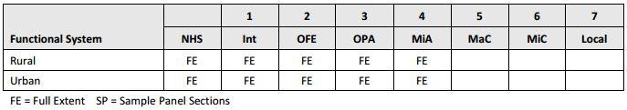
5 Item Value Calculation Method Predominance - The reported value must be based on the most prevalent value within the limits of the section. Numbers in parenthesis after the HPMS Items are the corresponding pages for that data item in the December 2016 FHWA HPMS Field Manual Data Items Data Item 1 Functional System (4-16) The Functional System Code is the responsibility of the Bureau of Planning and Research. 1 = Interstate (01 & 11) 2 = Principal Arterial Other Freeway/Expressway (12) 3 = Principal Arterial - Other (02 & 14) 4 = Minor Arterial (06 & 16) 5 = Major Collector (07 & 17) 6 = Minor Collector (08) 7 = Local (09 & 19) (#s) = Functional Class Codes used by PennDOT Data Item 3 Facility Type (4-18) This data item is the operational characteristic of the roadway, regardless of whether the section is on a structure. 2 Bureau of Planning and Research


6 1 = One-Way Roadway 2 = Two-Way Roadway 4 = Ramp 5 = Non-Mainline 6 = Non-Inventory Direction 7 = Planned/Unbuilt 1 - One-Way Roadway A roadway or structure section with traffic moving in one direction during non-peak period hours. 2 - Two-Way Roadway A roadway or structure section with traffic moving in both directions during non-peak period hours. 3 Bureau of Planning and Research


7 4 - Ramp A non-mainline junction or connector that is contained within a gradeseparated interchange. Source: Google Maps Lancaster, PA 5 - Non-Mainline A road or lane that provides access to and from sites that are adjacent to a roadway section such as bus terminals, park-and-ride lots, ramps to truck weigh stations, and rest areas. Source: FHWA HPMS Field Manual - Bing Maps 4 Bureau of Planning and Research

 This data item is the degree of access control")

8 6 - Non-Inventory Direction The non-inventory side of a multi-road roadway. Source: FHWA HPMS Field Manual - Bing Maps Data Item 5 Access Control (4-26) This data item is the degree of access control on the section. 1- Full Access Control Grade separated interchanges with selected public roads. No at-grade crossings. No direct driveway connections. 5 Bureau of Planning and Research


9 2- Partial Access Control Grade separated interchanges with selected public roads. Some at-grade crossings with selected public roads. Direct driveway connections have been minimized through the use of frontage roads or other local access restrictions. 3- No Access Control At-grade crossings. Direct driveway connections. Data Item 10 Peak Lanes (4-33) 6 Bureau of Planning and Research
 and High Occupancy Vehicle (HOV) operation.")

10 This data item is the number of through lanes in the peak direction of traffic flow on the section during the peak hour. Include reversible lanes, parking lanes, and shoulders that are legally used for through traffic for non-high Occupancy Vehicle (HOV) and High Occupancy Vehicle (HOV) operation. If the section is an urban roadway, code the peak direction. If the section is a rural roadway with 2-3 lanes, code both directions. If the section is a rural roadway with 4 or more lanes, code the peak direction. [(the number of peak lanes) + (the number of counter peak lanes)] (the number of through lanes) The peak period is represented by the period of the day when observed traffic volumes are the highest. One-Way Through Lanes - Peak Direction Two-Way Through Lanes - Peak Direction 7 Bureau of Planning and Research

 + (the number of counter peak lanes)] (the number of through lanes) For urban roads,")
 This data item is the type of right turning lanes or bays on the urban")
11 Data Item 11 Counter Peak Lanes (4-34) This data item is the number of through lanes used on the section in the counter peak direction during the peak hour. Include reversible lanes, parking lanes, and shoulders that are legally used for through traffic. [(the number of peak lanes) + (the number of counter peak lanes)] (the number of through lanes) For urban roads, code based on the counter peak direction of travel. For rural 2 or 3-lane roads, do not code this data item. Data Item 12 Turn Lanes - Right (4-34) This data item is the type of right turning lanes or bays on the urban section in the inventory direction during peak-period. 8 Bureau of Planning and Research

12 1 = No Intersections Exist on the Section 2 = Multiple Exclusive Right Turning Lanes 3 = Continuous Exclusive Right Turning Lane 4 = Single Exclusive Right Turning Lane 5 = Right Turns Allowed from Through Lane 6 = Right Turns not Allowed During Peak Period If the peak capacity for a section is governed by a controlling intersection, code the type of turning lanes at that controlling intersection. When determining the types of turning lanes on a section, include turning lanes that are located at entrances to shopping centers, industrial parks, and other large traffic generating facilities. Through traffic movement is prohibited in an exclusive turning lane. If a section has a signalized or stop sign intersection that is critical to the flow of traffic, code the type of turning lanes at that critical intersection. If a section does not have a controlling, signalized, or stop sign intersection, code the type of turning lanes during the peak hour for a typical intersection on the section. If an intersection has a continuous turning lane with a painted turn bay, code the intersection as a continuous turning lane. If through traffic and turning movements can be made from a lane at an intersection, it is not an exclusive turning lane. If a section has a roundabout, code the intersection as an intersection where turns are permitted and no exclusive right turning lane exists. Use code 6 when no right turn permitted signs are present at the intersection you choose as the busiest (most controlling). It should also be used if right turns cannot physically be made along the sample due to roadway conditions and access control is coded as 2 or 3. Use code 1 when access control is coded as No Intersection No intersections exist in the section. 9 Bureau of Planning and Research


13 2 - Multiple Right Turning Lanes Right turn is permitted from multiple exclusive right turning lanes. Through traffic movement is prohibited in these lanes. Multiple turning lanes allow for simultaneous turns from all turning lanes. 3 - Continuous Right Turning Lane Right turn is permitted from a continuous exclusive right turning lane. Through traffic movement is prohibited in these lanes. 4 - Single Right Turning Lane Right turn is permitted from a single exclusive right turning lane. 10 Bureau of Planning and Research


14 5 - Right Turn Allowed from Through Lane Right turn is allowed from a through lane. There is not an exclusive turning lane. 6 - Right Turns Not Allowed Data Item 13 Turn Lanes - Left (4-39) This data item is the type of left turning lanes or bays on the urban section in the inventory direction during peak period. 11 Bureau of Planning and Research
15 1 = No Intersections Exist on the Section 2 = Multiple Exclusive Left Turning Lanes 3 = Continuous Exclusive Left Turning Lane 4 = Single Exclusive Left Turning Lane 5 = Left Turns Allowed from Through Lane 6 = Left Turns not Allowed During Peak Period If the peak capacity for a section is governed by a controlling intersection, code the type of turning lanes at that controlling intersection. When determining the types of turning lanes on a section, include turning lanes that are located at entrances to shopping centers, industrial parks, and other large traffic generating facilities. Through traffic movement is prohibited in an exclusive turning lane. If a section has a signalized or stop sign intersection that is critical to the flow of traffic, code the type of turning lanes at that critical intersection. If a section does not have a controlling, signalized, or stop sign intersection, code the type of turning lanes during the peak-hour for a typical intersection on the section. If an intersection has a continuous turning lane with a painted turn bay, code the intersection as a continuous turning lane. If through traffic and turning movements can be made from a lane at an intersection, it is not an exclusive turning lane. Use code 6 when no left turn permitted signs are present at the intersection you choose as the busiest (most controlling). It should also be used if left turns cannot physically be made along the sample due to roadway conditions and access control is coded as 2 or 3. Use code 1 when access control is coded as No Intersection No intersections exist in the section. 12 Bureau of Planning and Research


16 2 - Multiple Left Turning Lanes Left turn is permitted from multiple exclusive left turning lanes. Through traffic movement is prohibited in these lanes. Multiple turning lanes allow for simultaneous turns from all turning lanes. 3 - Continuous Left Turning Lane Left turn is permitted from a continuous exclusive left turning lane. Through traffic movement is prohibited in these lanes. 4 - Single Left Turning Lane Left turn is permitted from a single exclusive left turning lane. 13 Bureau of Planning and Research


17 5 - Left Turn Allowed from Through Lane Left turn is allowed from a through lane. There is not an exclusive turning lane. 6 - Left Turns Not Allowed Data Item 14 Speed Limit (4-44) Use the Vehicle Code Title 75 if the speed limit is not posted. 35 mph in any urban district (boroughs, cities) 25 mph in a residential district if the roadway is one of the following: o Not a numbered traffic route o Functionally classified as a local highway. 55 mph in other locations If the speed limit changes within a section, report the predominant speed limit. 14 Bureau of Planning and Research
. If two or more routes of differing functional systems are assigned along a roadway section (i.e. Interstate 78 and US 22), code the data item in accordance with the highest functional system on the route (in this example, Interstate 78).")
, code the highest order identifier on the route (in this example, Interstate 83).")
18 Data Item 17 Route Number (4-47) If two or more routes of the same functional system are signed along a roadway section (i.e. US 11 and US 15), code the lowest route number (i.e., US 11). If two or more routes of differing functional systems are assigned along a roadway section (i.e. Interstate 78 and US 22), code the data item in accordance with the highest functional system on the route (in this example, Interstate 78). Data Item 18 Route Signing (4-48) 1 = Not Signed 6 = County 2 = Interstate 7 = Township 3 = US 8 = Municipal 4 = State 9 = Parkway/Forest Marker 5 = Off-Interstate Business Marker 10 = None of the Above When a section is signed with two or more identifiers (i.e. Interstate 83 and US 322), code the highest order identifier on the route (in this example, Interstate 83). Follow the hierarchy as ordered above. 15 Bureau of Planning and Research


19 Data Item 19 Route Qualifier (4-49) 1 = No Qualifier/Not Signed 6 = Loop 2 = Alternate 7 = Proposed 3 = Business Route 8 = Temporary 4 = Bypass Business 9 = Truck Route 5 = Spur 10 = None of the Above 16 Bureau of Planning and Research
, Pacific Coast Highway (CA) and the Garden State Parkway (NJ).")

20 Data Item 20 Alternate Route Name (4-51) A non-numeric designation for a route. Examples for this data item would be Schuylkill Expressway (PA), Pacific Coast Highway (CA) and the Garden State Parkway (NJ). Data Item 29 Signal Type (4-61) As a best practice, contact the respective PennDOT Engineering District for the signals in question to obtain information on the type of signal and green time. 1 = Uncoordinated Fixed Time 2 = Uncoordinated Traffic Actuated 3 = Coordinated Progressive (coordinated signals through several intersections) 4 = Coordinated Real-time Adaptive 5 = No signal system exists 17 Bureau of Planning and Research
21 Data Item 30 Percent Green Time (4-63) This data item is the percentage of green time allocated during peak period (i.e. 7am 9am or 4pm 6pm) for through traffic at signalized intersections on the section in the inventory direction. If the section has more than one signalized intersection, calculate the percent green time at the predominate intersection. If the signal has a green arrow for turning movements, do not include the green arrow time for timing of the green cycle. Uncoordinated Traffic Actuated Signals require a value. To Calculate Percent Green Time 1. Using a stop watch, time the entire signal cycle (red, amber, and green) in seconds. 2. Using a stop watch, time the green signal cycle in seconds. 3. Percent Green Time = [(green signal cycle time)/ (entire signal cycle time)] * Record the time and repeat Steps 1-3 three times. 5. Add the percent green times and divide by Average percent green time = [(percent green time) + (percent green time) + (percent green time)] / 3 Data Item 31 Number Signals (4-65) This data item is the number of signalized at-grade intersections on the section that control traffic in the inventory direction. A signalized intersection has a traffic signal which cycles through red, amber, and green. If the access point to a large traffic generator (i.e. shopping centers, malls, large work sites, office parks, apartment complexes, and subdivisions) is controlled by a traffic signal, the access point is considered an intersection. If a section begins and ends at a signalized intersection, only count the ending intersection. Do not count the beginning intersection. If the section has a continuous cross street on a divided highway, count the intersections as a single intersection. 18 Bureau of Planning and Research
 This data item is the number of stop sign controlled at-grade intersections on the section that control traffic in the inventory direction.")
22 If the section has a non-continuous cross street that is separated by a minimum of 50 feet, count both intersections. Data Item 32 Stop Signs (4-66) This data item is the number of stop sign controlled at-grade intersections on the section that control traffic in the inventory direction. If an intersection is controlled by a continuously operating flashing red signal, count the intersection as a Stop Sign Controlled Intersection. Do not count stop signs on the intersecting roads. If the access point to a large traffic generator (i.e. shopping centers, malls, large work sites, office parks, apartment complexes, and subdivisions) is controlled by a stop sign, the access point is considered an intersection. If a section begins and ends at a stop-sign controlled intersection, only count the ending intersection. Do not count the beginning intersection. If the section has a non-continuous cross street that is separated by a minimum of 50 feet, count both intersections. Data Item 33 At Grade Other (4-68) 19 Bureau of Planning and Research
23 This data item is the number of at-grade intersections on the section in the inventory direction where traffic is not controlled by either a signal or a stop sign; is controlled by other types of signage or some other devices. If an intersection is controlled by a continuously operating flashing yellow signal, count the intersection as an At Grade Other Intersection. If the access point to a large traffic generator (i.e. shopping centers, malls, large work sites, office parks, apartment complexes, and subdivisions) is controlled by a stop sign, the access point is considered an intersection. If a section begins and ends at an intersection controlled by a device other than a traffic signal or stop sign, only count the ending intersection. Do not count the beginning intersection. If an intersection is a roundabout, code as At Grade Other Intersection. At Grade Other intersections are not counted on the opposite side of the sample on divided highways with medians, unless a crossover lane exists. If the cross street is not continuous and is separated by at least 50 feet, then it should be counted as two intersections. Data Item 34 Lane Width (4-70) This data item is the measure of the existing lane width, rounded to the nearest foot. Although RMS has minimum (6 feet) and maximum (18 feet) allowable entries, please report the actual measured lane widths. To Measure Lane Width Measure the prevailing through lane width. Round the value to the nearest foot. When striping exists, count the lane width from paint line to paint line. 20 Bureau of Planning and Research


24 When striping is placed inside the edge of the pavement, to keep traffic from breaking the pavement edge, ignore the striping and measure from the pavement edge to the center of a single center stripe, or, if double striping exists, measure to the center of the two stripes. If parking is allowed, use six to eight feet for parking. The remaining distance would be your lane width. Remain consistent with all samples, unless there are painted parking lines. Where there is no delineation between the through traffic lane and the shoulder or parking lane, or where there is no centerline, measure the entire width of roadway, divide by 2, and deduct the parking width. Report the actual lane width. If more than one lane exists, measure all lanes in the inventory direction and use the average value to the nearest foot. If widths vary over the sample section use the predominant width. 2 Lane Road Measure from the white stripe to the center of the double yellow stripe. Round the value to the nearest foot. 21 Bureau of Planning and Research


25 3 Lane Road Measure from the white stripe to the center of the double yellow stripe and divide the value by 2. Round the value to the nearest foot. 4 Lane Road Measure from the white stripe to the center of the double yellow stripe and divide the value by 2. Round the value to the nearest foot. No Shoulder Measure between the points where the edge of the road appears to break away and slope toward the ditch and divide the value by 2. Round the value to the nearest foot. 22 Bureau of Planning and Research


26 No Center Line Measure the full width of the road and divide the value by 2. Round the value to the nearest foot. If the gutter has been filled during overlay, measure between the points where the edge of the road meets the curb face and divide the value by 2. Interstate Measure one lane. Round the value to the nearest foot. Bike Lanes PennDOT Publication 13M Defined as a portion of a roadway which has been designated by striping, signing, and pavement markings for the preferential or exclusive use of bicyclists. A bicycle symbol with directional arrows placed on the roadway designate Marked Shared Lanes as defined in the AASHTO Guide for the Development of Bicycle Facilities 2012, Fourth Edition and MUTCO. This is not a designated bike lane and should not be marked on the sample sheet as Y bike lane exists. Do not include bike lane width in shoulder with if shoulder exists along with a bike lane. Do not include bike lane width in travel lane width. 23 Bureau of Planning and Research


27 Data Item 35 Median Type (4-71) This data item is the type of median on the section. A median is the portion of a divided highway that is separating the traveled way for traffic in opposing directions. 1 = None 2 = Unprotected 3 = Curbed 4 = Positive Barrier Unspecified 5 = Positive Barrier Flexible 6 = Positive Barrier Semi-Rigid 7 = Positive Barrier Rigid 1- None No median or an unprotected area less than 4 feet wide. 24 Bureau of Planning and Research


28 2- Unprotected A median without a barrier and 4 or more feet wide. 3- Curbed A median with a barrier or mountable curb with a minimum height of 4 inches. 4- Unspecified - Positive Barrier Only to be used when thick impenetrable vegetation exists. Use codes 5, 6, or 7 when coding man-made positive barriers. 25 Bureau of Planning and Research


29 5- Positive Barrier Flexible A median with a flexible positive barrier. Considerable deflection of vehicle upon impact. 6 Positive Barrier Semi-Rigid A median with a semi-rigid positive barrier. Some deflection of vehicle upon impact. 7- Positive Barrier Rigid A median with a rigid positive barrier. No deflection of vehicle upon impact. 26 Bureau of Planning and Research


30 Data Item 36 Median Width (4-73) This data item is the width of the median on the section, rounded to the nearest foot. Enter 999 where the median width is 1000 feet or greater. Median width should be the predominant width including any left shoulders. Measure between the inside edges of the through lanes. Data Item 37 Shoulder Type (4-74) If the shoulder type varies over the extent of the section, code the predominant Shoulder Type. If the left and right shoulder types are different shoulder types, code the right shoulder type as the predominant Shoulder Type. If there is a shoulder in front of a barrier curb, code the Shoulder Type and Shoulder Width. Code the shoulder if it is at least one foot (1ft) or greater. Do not code the area behind the barrier curb as a shoulder. Ignore mountable curbs. If there is a shoulder in front of or behind a mountable curb, code the Shoulder Type and Shoulder Width. If the section has parking abutting the through lane, there is not an area that is considered a shoulder. Code as No Shoulder (code value 1). 27 Bureau of Planning and Research
.")
31 1- None A bike lane must be signed or delineated by pavement markings to be considered a bike lane. If the section has a bike lane abutting the through lane, there is not an area that is considered a shoulder. Code as No Shoulder (code value 1). If there is parking abutting the through-lane, there is not an area that is considered a shoulder. Code as No Shoulder (code value 1). If there is parking on one side of a divided roadway and a shoulder or a curb on the other side, code the Peak Parking Type, Shoulder Type, and Shoulder Width. If there is a surface type change between the lane and curb or striping is present, code the Shoulder Type and Shoulder Width. Do not use combination shoulder, code 5. Local Federal Aid Route Samples ONLY o If a barrier curb and paved shoulder appear to exist simultaneously: If no striping exists, code as Barrier Curb. If striping exists and measurement from curb to white line is less than 6 feet, code as Barrier Curb. If striping exists and measurement from curb to white line is 6 feet or greater, code the Shoulder Type and Shoulder Width. For State Highway Samples o Do not change Shoulder Type the District has chosen. 1= None 2= Surfaced bituminous 3= Surfaced concrete 4= Stabilized 5= Combination 6= Earth 7= Barrier Curb no shoulder in front of curb 28 Bureau of Planning and Research


32 2- Surfaced-bituminous 3- Surfaced-concrete Source: FHWA HPMS Field Manual 4- Stabilized Source: FHWA HPMS Field Manual 29 Bureau of Planning and Research
 because 90% of PA")


33 5- Combination Source: FHWA HPMS Field Manual Do not use a code 5 (combination) because 90% of PA shoulders would be a Earth Example: If the shoulder cross section is 2 foot paved and 3 foot stabilized, record the surface type as stabilized, Type Barrier Curb/No Shoulder 30 Bureau of Planning and Research


34 Data Item 38 Shoulder Width - Right (4-77) Do not include parking or bicycle lanes in the shoulder width. This data item is the width of the right shoulder, rounded to the nearest foot. Where the width changes along the sample, code the predominant width Include rumple strips and gutter pans Measure to the nearest foot Data Item 39 Shoulder Width - Left (4-79) 31 Bureau of Planning and Research

 This data item is the type of")
35 This data item is the width of the left shoulder on a divided highway, rounded to the nearest foot. Do not include parking or bicycle lanes in the shoulder width. Left shoulders are only coded on a divided Highway If median width and left shoulder width combined is less than 4 feet, then the left shoulder width is zero. Code left shoulder widths only if median and left shoulder width combined is more than 4 feet. Where the width changes along the sample, code the predominant width Include rumple strips and gutter pans Measure to the nearest foot Data Item 40 Peak Parking (4-80) This data item is the type of parking on the section during the peak hour. If parking is available beyond the shoulder, code as No Parking Allowed (code value 3) Code Interstates and Freeways as No Parking Allowed (code value 3). If parking lanes are used for through traffic or turning lanes during the peak hour, code the in-use condition. 1 = Parking Allowed on One Side 2 = Parking Allowed on Both Sides 3 = No Parking Allowed 32 Bureau of Planning and Research


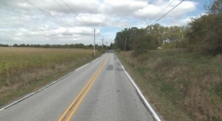
36 1 - Parking Allowed On One Side 2 - Parking Allowed On Both Sides 3 No Parking Allowed (Rural Roadway) 33 Bureau of Planning and Research

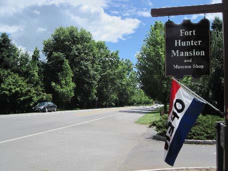
37 Data Item 41 Widening Obstacle (4-82) This data item is the types of obstacles that prevent the widening of the existing roadway for additional through lanes. One or more types of obstacles can be entered. Code obstacles that are within approximately 100 feet of the outer edge of the through lanes in either direction on the section. Code all conditions that apply in either direction, on either side of the section. Enter any combination of multiple codes. Code X - no obstacles, cannot be used in combination of another code. If Data Item 42 (Widening Potential) is coded 8 lanes or less, then this data item should be coded A through G. X = No Obstacles A = Dense Development B = Major Transportation Facilities C = Other Public Facilities D = Terrain Restrictions E = Historic/Archaeological Sites F = Environmentally Sensitive Areas G = Parkland X No Obstacles 34 Bureau of Planning and Research


 35 Bureau of")
38 A Dense Development B Major Transportation Facilities C Other Public Facilities (i.e. School, Hospital, and Library) 35 Bureau of Planning and Research


39 D Terrain Restrictions E Historic/Archaeological Sites 36 Bureau of Planning and Research


40 F Environmentally Sensitive Areas G Parkland 37 Bureau of Planning and Research


41 Data Item 42 Widening Potential (4-84) This data item is the number of through lanes that could be potentially added to the roadway, in both directions. If more than 9 through lanes could be potentially added, code as 9 lanes. Code this item based on how feasible it is to widen the existing roadway, based on the presence of obstacles and the proximity of the obstacle to the roadway. Consider medians, areas within the existing right-of-way, and areas outside the existing right-of-way to be available for widening. Do not consider restriction because of current right-of-way width or projected traffic. Restriping to narrower lanes, resulting in an additional lane on a multi-lane roadway does not constitute widening potential. Data Item 44 Terrain Type (4-87) To determine terrain type, consider that terrain of an extended length of the roadway of the section, rather than the grade on the specific Sample Panel section. Terrain type should be collected on Rural sample sections only. 1 = Level 2 = Rolling 3 = Mountainous 38 Bureau of Planning and Research


42 1 - Level Terrain Any combination of grades and horizontal or vertical alignment that permits heavy vehicles to maintain the same speed as passenger cars. This includes short grades of not more than 2 percent. 2 - Rolling Terrain Any combination of grades and horizontal or vertical alignment that causes heavy vehicles to reduce their speeds substantially below those of passenger cars, but does not cause heavy vehicles to operate at crawl speeds for any significant length of time. 39 Bureau of Planning and Research
 This data item is the percentage of a section that meets the sight distance requirement for passing.")
43 3 - Mountainous Terrain Any combination of grades and horizontal or vertical alignment that causes heavy vehicles to operate at extremely low speeds for significant distances or at frequent intervals. Data Item 46 Percent Pass Sight (4-90) This data item is the percentage of a section that meets the sight distance requirement for passing. When there is a pronounced directional difference, code for the more restrictive direction. All rural, paved, 2-lane Sample Panel sections. The percentage of passing sight distance = [(the length of the section that is striped for passing allowed) / (the length of the section)] * Bureau of Planning and Research


44 Passing Allowed in Both Directions of Travel Passing Not Allowed in Inventory Direction of Travel Passing Not Allowed in Non-Inventory Directions of Travel 41 Bureau of Planning and Research

45 Passing Not Allowed in Either Direction of Travel 42 Bureau of Planning and Research
 This data item is the average depth of pavement rutting on the section, rounded to the nearest 0.1 inch.")
46 The following data items are to be visually verified in the field and should be noted if they do not appear to be accurate. Actual measurements are not to be completed. Data Item 50 Rutting (4-99) This data item is the average depth of pavement rutting on the section, rounded to the nearest 0.1 inch. A rut is a longitudinal surface depression in the wheel path of the pavement and it may have associated transverse displacement. Source: FHWA HPMS Field Manual - LTPP Distress & Identification Manual Measure the pavement rutting and round the value to the nearest 0.1 inch. Measure each wheel path of the pavement in multiple locations and average the values. Pavement rutting data is collected on a 2-year cycle. 43 Bureau of Planning and Research

47 Source: FHWA HPMS Field Manual TXDOT, Construction Division Data Item 51 Faulting (4-102) This data item is the average depth of pavement faulting on the section, rounded to the nearest 0.1 inch. Pavement faulting is the vertical displacement between adjacent jointed concrete panels in the direction of travel. Source: FHWA HPMS Field Manual - LTPP Distress & Identification Manual 44 Bureau of Planning and Research
 For Asphalt Concrete (AC) pavement, the estimated percentage of the")

48 Pavement faulting data is collected on a 2-year cycle. Measure every jointed concrete panel and average the values. Source: FHWA HPMS Field Manual TXDOT, Construction Division Data Item 52 Cracking Percent (4-106) For Asphalt Concrete (AC) pavement, the estimated percentage of the area with fatigue cracking in the wheel path. Round the percentage to the nearest percent. Example: The fatigue cracking in the sample is 500 feet long and 2 feet wide in each wheel path. (500 feet) x (2 feet) x (2 wheel paths) = 2000 square feet (2000 square feet) / (63,360 square feet) = 3.2 percent Rounding 3.2 percent to the nearest percent = 3 percent 45 Bureau of Planning and Research

49 Longitudinal Cracking Alligator Cracking Data Item 54 Year Last Improvement (4-116) The year in which the roadway surface was last improved. 0.5 inch or more of compacted pavement material must be put in place for it to be considered a surface improvement. Completion date is the actual date the construction ended or the date when the project was opened to traffic. Retain the coded improvement year until another improvement affecting the surface is completed. 46 Bureau of Planning and Research

50 Data Item 55 Year Last Construction (4-117) The year in which the roadway was constructed or reconstructed. Reconstruction is the replacement of the existing pavement structure with an equivalent or increased structure. Although recycled materials may be used in the new pavement structure, reconstruction usually requires the complete removal and replacement of at least the old pavement surface, and often also the base. If a new pavement surface were placed without first removing the old pavement surface, the resulting pavement should be considered an overlay (surface improvement, not construction Data Item 56), even if the existing pavement was rubblized prior to placing the new pavement surface. Data Item 56 Last Overlay Thickness (4-118) Thickness of the most recent pavement overlay. Reporting should be consistent with IRI inventory direction and lane. Values can also be obtained from construction plans for use in the Table. An overlay is more than 0.5 inch. 47 Bureau of Planning and Research
51 NOTES 48 Bureau of Planning and Research
52 NOTES 49 Bureau of Planning and Research
53 NOTES 50 Bureau of Planning and Research
54 NOTES 51 Bureau of Planning and Research
PENNDOT HPMS DATA COLLECTION GUIDE. Bureau of Planning and Research Transportation Planning Division April 2016 (Updated March 2018)
") PENNDOT HPMS DATA COLLECTION GUIDE Bureau of Planning and Research April 2016 (Updated March 2018) State Street Dauphin County NOTES INTRODUCTION The purpose of this document is to provide you with some
PENNDOT HPMS DATA COLLECTION GUIDE Bureau of Planning and Research April 2016 (Updated March 2018) State Street Dauphin County NOTES INTRODUCTION The purpose of this document is to provide you with some
Appendix B Existing ADOT Data Parameters
 Appendix B Existing ADOT Data Parameters Appendix 08/04/03 HPMS by Item Number All records 1 Year of Submittal 2 State Code 3 English or Metric Reporting Units 4 County Code 5 Section Identification (ID)
WYDOT DESIGN GUIDES. Guide for. NHS Arterial (Non-Interstate)
") WYDOT DESIGN GUIDES Guide for NHS Arterial (Non-Interstate) 2014 GUIDE FOR NATIONAL HIGHWAY SYSTEM (NHS) HIGHWAYS (NHS ARTERIALS, Non-Interstate) PRESERVATION REHABILITATION RECONSTRUCTION INTRODUCTION
WYDOT DESIGN GUIDES Guide for NHS Arterial (Non-Interstate) 2014 GUIDE FOR NATIONAL HIGHWAY SYSTEM (NHS) HIGHWAYS (NHS ARTERIALS, Non-Interstate) PRESERVATION REHABILITATION RECONSTRUCTION INTRODUCTION
WYDOT DESIGN GUIDES. Guide for. Non-NHS State Highways
 WYDOT DESIGN GUIDES Guide for Non-NHS State Highways 2014 GUIDE FOR Non-NATIONAL HIGHWAY SYSTEM (Non-NHS) STATE HIGHWAYS PRESERVATION REHABILITATION RECONSTRUCTION INTRODUCTION This Guide is directed to
Section 3A.04 Colors. Section 3B.10 Approach Markings for Obstructions
 Section 3A.04 Colors Markings shall be yellow, white, red, or blue, or purple. The colors for markings shall conform to the standard highway colors. Black in conjunction with one of the above colors shall
Recommended Roadway Plan Section 2 - Land Development and Roadway Access
 Recommended Roadway Plan Section 2 - Land Development and Roadway Access SECTION 2 Land Development and Roadway Access 2.1 Land Use and Access Management The Federal Highway Administration (FHWA) defines
CHAPTER 2G. PREFERENTIAL AND MANAGED LANE SIGNS
 2011 Edition - Revision 2 Page 275 Section 2G.01 Scope CHAPTER 2G. PREFERENTIAL AND MANAGED LANE SIGNS 01 Preferential lanes are lanes designated for special traffic uses such as high-occupancy vehicles
This Chapter sets forth the minimum design, technical criteria and specifications to be used in the preparation of all roadway plans.
 4.1 GENERAL This Chapter sets forth the minimum design, technical criteria and specifications to be used in the preparation of all roadway plans. These Roadway Standards are for new construction and modification
MNDOT PAVEMENT DESIGN MANUAL
 MNDOT PAVEMENT DESIGN MANUAL Chapter 6 Ramps, Shoulders, Turn Lanes & Miscellaneous Pavements MnDOT Pavement Engineer Date Contents Introduction... 1 600 Ramps and Loops... 1 610 - Shoulders... 2 620 -
Chapter 4 On-Road Bikeways
 Chapter 4: 4-1.0 Introduction On-Road Bikeways This chapter provides guidelines to help select and design safe on-road bikeways. On-road bikeways include bicycle lanes, shared lanes, shoulders, and wide
MUTCD Part 6G: Type of Temporary Traffic Control Zone Activities
 MUTCD Part 6G: Type of Temporary Traffic Control Zone Activities 6G.01 Typical Applications Each temporary traffic control (TTC) zone is different. Many variables, such as location of work, highway type,
General References Definitions. (1) Design Guidance. (2) Supporting Information
 Design Guidance. (2) Supporting Information") Chapter 1240 Turning Roadways 1240.01 General 1240.02 References 1240.03 Definitions 1240.04 Turning Roadway Widths 1240.05 Documentation 1240.01 General The roadway on a curve may need to be widened to
Chapter 1240 Turning Roadways 1240.01 General 1240.02 References 1240.03 Definitions 1240.04 Turning Roadway Widths 1240.05 Documentation 1240.01 General The roadway on a curve may need to be widened to
Figure 3B-1. Examples of Two-Lane, Two-Way Marking Applications
 Figure 3B-1. Examples of Two-Lane, Two-Way Marking Applications A - Typical two-lane, two-way marking with passing permitted in both directions B - Typical two-lane, two-way marking with no-passing zones
Paul Huston, P.E., Design-Build Coordinator Chuck Gonderinger, HDR Engineering. Minnesota Department of Transportation (the Department)
") To: From: Paul Huston, P.E., Design-Build Coordinator Chuck Gonderinger, HDR Engineering Date: March 20, 2001 Subject: Roadway Geometric Design Criteria Project: TH 14/218 Design-Build Project, SP 7408-29,
To: From: Paul Huston, P.E., Design-Build Coordinator Chuck Gonderinger, HDR Engineering Date: March 20, 2001 Subject: Roadway Geometric Design Criteria Project: TH 14/218 Design-Build Project, SP 7408-29,
October 2004 REVISIONS (2) SUPERELEVATION DEVELOPMENT 11.3(2)
 SUPERELEVATION DEVELOPMENT 11.3(2)") October 2004 REVISIONS (2) Chapter 11 HORIZONTAL ALIGNMENT SUPERELEVATION DEVELOPMENT 11.3(2) Chapter 12 VERTICAL ALIGNMENT VERTICAL CURVES PASSING SIGHT DISTANCE 12.5(2) VERTICAL CURVES STOPPING SIGHT
October 2004 REVISIONS (2) Chapter 11 HORIZONTAL ALIGNMENT SUPERELEVATION DEVELOPMENT 11.3(2) Chapter 12 VERTICAL ALIGNMENT VERTICAL CURVES PASSING SIGHT DISTANCE 12.5(2) VERTICAL CURVES STOPPING SIGHT
TRAFFIC LINE MANUAL. June 2011 TRAFFIC-ROADWAY SECTION
 TRAFFIC LINE MANUAL TRAFFIC-ROADWAY SECTION TABLE OF CONTENTS Foreword...iv Section A: General Principles A-1 Functions and Limitations... 1 A-2 Colors... 1 A-3 Colored Pavements... 1 A-4 Functions, Widths,
Active Transportation Facility Glossary
 Active Transportation Facility Glossary This document defines different active transportation facilities and suggests appropriate corridor types. Click on a facility type to jump to its definition. Bike
TRAFFIC LINE MANUAL Edition Revision 1 June 2012 TRAFFIC-ROADWAY SECTION
 TRAFFIC LINE MANUAL 2011 Edition Revision 1 June 2012 TRAFFIC-ROADWAY SECTION TABLE OF CONTENTS Foreword...iv Section A: General Principles A-1 Functions and Limitations... 1 A-2 Colors... 1 A-3 Colored
Dr. Naveed Anwar Executive Director, AIT Consulting Affiliated Faculty, Structural Engineering Director, ACECOMS
 Dr. Naveed Anwar Executive Director, AIT Consulting Affiliated Faculty, Structural Engineering Director, ACECOMS Overview Highway Functions and Classifications Highway Design Components Design Control
Multimodal Through Corridors and Placemaking Corridors
 68 Multimodal Through Corridors and Placemaking Corridors Corridors have different functions in a region. Some corridors are used to get smoothly and rapidly through a region or to get quickly to major
CHAPTER 1 STANDARD PRACTICES
 CHAPTER 1 STANDARD PRACTICES OBJECTIVES 1) Functions and Limitations 2) Standardization of Application 3) Materials 4) Colors 5) Widths and Patterns of Longitudinal Pavement Marking Lines 6) General Principles
Geometric Design Tables
 Design Manual Chapter 5 - Roadway Design 5C - Geometric Design Criteria 5C-1 Geometric Design Tables A. General The following sections present two sets of design criteria tables - Preferred Roadway Elements
Driveway Design Criteria
 Design Manual Chapter 5 - Roadway Design 5L - Access Management 5L-4 Driveway Design Criteria A. General For efficient and safe operations, access drives and minor public street intersections can be improved
Alberta Infrastructure HIGHWAY GEOMETRIC DESIGN GUIDE AUGUST 1999
 Alberta Infrastructure HIGHWAY GEOMETRIC DESIGN GUIDE AUGUST 1999,1'(; A ACCELERATION Data on acceleration from stop D-29 Effects of grade D-35 Intersections D-97, D-99 Lanes D-97, F-5, F-7, F-15, F-21,
Appendix 3 Roadway and Bike/Ped Design Standards
 Appendix 3 Roadway and Bike/Ped Design Standards OTO Transportation Plan 2040 4/20/2017 Page A3-1 Adopted Standards The adopted OTO Design Standards and Major Thoroughfare Plan are contained herein.
CHAPTER 3A. GENERAL PAGE CHAPTER 3B. PAVEMENT AND CURB MARKINGS PAGE
 Virginia Supplement to the 2009 MUTCD Revision 1 Page TC-3-1 PART 3. MARKINGS CHAPTER 3A. GENERAL PAGE Section 3A.01 Functions and Limitations Section 3A.02 Standardization of Application Section 3A.03
T A B L E OF C O N T E N T S
 T A B L E OF C O N T E N T S PART III SUBDIVISION REGULATIONS OF THE DEPARTMENT OF PUBLIC WORKS, C & C D PAGE PAGE Responsibility for Development of Streets......... 29 Right-of-Way Widths...... 37 Purpose...........
THE FUTURE OF THE TxDOT ROADWAY DESIGN MANUAL
 THE FUTURE OF THE TXDOT ROADWAY DESIGN MANUAL Kenneth Mora, P.E. (Design Division) 10/10/2017 Table of contents 1 2 Reduction in FHWA design controlling criteria Innovative Intersection Guidance 3-7 8-42
ROUNDABOUTS/TRAFFIC CIRCLES
 GENERAL 1. Description This standard identifies minimum requirements that shall be met for Roundabouts and Neighborhood Traffic Circles in the design and construction of elements for Arlington County Horizontal
City of Wayzata Comprehensive Plan 2030 Transportation Chapter: Appendix A
 A1. Functional Classification Table A-1 illustrates the Metropolitan Council s detailed criteria established for the functional classification of roadways within the Twin Cities Metropolitan Area. Table
CHAPTER 6H. TYPICAL APPLICATIONS
 Section 6H.01 Typical Applications Support: CHAPTER 6H. TYPICAL APPLICATIONS Chapter 6G contains discussions of typical temporary traffic control activities. Chapter 6H presents typical applications for
Developed by: The American Traffic Safety Services Association (ATSSA) 15 Riverside Parkway, Suite 100 Fredericksburg, VA
 15 Riverside Parkway, Suite 100 Fredericksburg, VA") Addendum Developed by: The American Traffic Safety Services Association (ATSSA) 15 Riverside Parkway, Suite 100 Fredericksburg, VA 22406-1022 800-272-8772 This material is based upon work supported by
Addendum Developed by: The American Traffic Safety Services Association (ATSSA) 15 Riverside Parkway, Suite 100 Fredericksburg, VA 22406-1022 800-272-8772 This material is based upon work supported by
MEMORANDUM TERESA MCCLISH, COMMUNITY DEVELOPMENT DIRECTOR SUBJECT: CONSIDERATION OF RESTRICTING PARKING ADJACENT TO 170 AND 171 BRISCO ROAD
 MEMORANDUM TO: FROM: BY: TRAFFIC COMMISSION TERESA MCCLISH, COMMUNITY DEVELOPMENT DIRECTOR MATT HORN, CITY ENGINEER SUBJECT: CONSIDERATION OF RESTRICTING PARKING ADJACENT TO 170 AND 171 BRISCO ROAD DATE:
Access requests to County streets and roadways are processed through one of the following methods:
 13.1 GENERAL APPLICATION PROCESS Access requests to County streets and roadways are processed through one of the following methods: A. Planned Developments may set general locations for access points.
GDOT Cross Section Elements. Course ID: GDOT PDH Credits
 GDOT Cross Section Elements Course ID: GDOT-01 2 PDH Credits Civil Engineer Educators LLC 1026 Timberwolf Lane Juneau, AK 99801 Email: support@civilpdh.com Chapter 6 Contents 6. CROSS SECTION ELEMENTS
INDEX. Geometric Design Guide for Canadian Roads INDEX
 Acceleration lane, see Lanes, Acceleration Access, 8.1 Access Management and Functional Classification 8.2 Access Management by Design Classification 8.3 Access Configuration 8.4 Building Set-Back Guidelines
Roadway Design Manual
 Roadway Design Manual Manual Notice Archive by Texas Department of Transportation (512) 302-2453 all rights reserved Manual Notice 2009-1 From: Manual: Mark A. Marek, P.E Roadway Design Manual Effective
Session 1 23 CFR 772: Type I Project Definitions
 Session 1 23 CFR 772: Type I Project Definitions Facilitator: Carole Newvine, Oregon DOT Participants: Carole Newvine, Oregon DOT Mariano Berrios, Florida DOT Tom Hanf, Michigan DOT Greg Smith, North Carolina
City of Roseville Section 13 Design Standards. _Bikeways January 2016 SECTION 13 BIKEWAYS
 SECTION 13 BIKEWAYS 13-1 GENERAL The City of Roseville bikeway standards are designed to insure that transportation and recreational bikeways are constructed in a manner that would provide a safe and comfortable
SECTION 3 STREET DESIGN
 3.01 GENERAL SECTION 3 STREET DESIGN For purposes of geometric and structural design, streets shall be classified according to the following table. The City Engineer will determine the class of all proposed
CHAPTER 16 PEDESTRIAN FACILITIES DESIGN AND TECHNICAL CRITERIA TABLE OF CONTENTS
 CHAPTER 16 PEDESTRIAN FACILITIES DESIGN AND TECHNICAL CRITERIA TABLE OF CONTENTS Section Title Page 16.1 General... 16-1 16.1.1 AASHTO Reference... 16-1 16.1.2 ADA Requirements... 16-1 16.2 Sidewalks...
Chapter 3 DESIGN SPECIFICATIONS
 Brampton PathWays Planning and Design Guidelines 27 Chapter 3 DESIGN SPECIFICATIONS 3.1 CLASS 1 MULTI-USE PATH Off-road multi-use trails are the backbone of the Brampton PathWays Network. They are typically
RURAL HIGHWAY SHOULDERS THAT ACCOMMODATE BICYCLE AND PEDESTRIAN USE (TxDOT Project ) June 7, Presented by: Karen Dixon, Ph.D., P.E.
 June 7, Presented by: Karen Dixon, Ph.D., P.E.") RURAL HIGHWAY SHOULDERS THAT ACCOMMODATE BICYCLE AND PEDESTRIAN USE (TxDOT Project 0-6840) June 7, 2016 Presented by: Karen Dixon, Ph.D., P.E., TTI Team: Kay Fitzpatrick, Raul Avelar, & Subasish Das Project
RURAL HIGHWAY SHOULDERS THAT ACCOMMODATE BICYCLE AND PEDESTRIAN USE (TxDOT Project 0-6840) June 7, 2016 Presented by: Karen Dixon, Ph.D., P.E., TTI Team: Kay Fitzpatrick, Raul Avelar, & Subasish Das Project
Off-road Trails. Guidance
 Off-road Trails Off-road trails are shared use paths located on an independent alignment that provide two-way travel for people walking, bicycling, and other non-motorized users. Trails specifically along
Figure 1: Graphical definitions of superelevation in terms for a two lane roadway.
 Iowa Department of Transportation Office of Design Superelevation 2A-2 Design Manual Chapter 2 Alignments Originally Issued: 12-31-97 Revised: 12-10-10 Superelevation is the banking of the roadway along
CHAPTER 6H. TYPICAL APPLICATIONS
 2006 Edition Page 6H-1 CHAPTER 6H. TYPICAL APPLICATIONS Section 6H.01 Typical Applications Support: Whenever the acronym TTC is used in this Chapter, it refers to temporary traffic control. Standard: The
Access Management in the Vicinity of Intersections
 Access Management in the Vicinity of Intersections FHWA-SA-10-002 Technical Summary Photo: Ralph Bentley (used with permission) 0 Access Management is: The design, implementation and management of entry
Chapter Twenty-eight SIGHT DISTANCE BUREAU OF LOCAL ROADS AND STREETS MANUAL
 Chapter Twenty-eight SIGHT DISTANCE BUREAU OF LOCAL ROADS AND STREETS MANUAL Jan 2006 SIGHT DISTANCE 28(i) Chapter Twenty-eight SIGHT DISTANCE Table of Contents Section Page 28-1 STOPPING SIGHT DISTANCE
GEOMETRIC DESIGN STANDARDS FOR NEW RESIDENTIAL SUBDIVISION STREETS TABLE 1A CG-6 CURB AND GUTTER SECTION
 TABLE 1A CG-6 CURB AND GUTTER SECTION HORIZONTAL AND VERTICAL CONTROLS CURB AND GUTTER ROADWAYS MAXIMUM 3:1 CUT OR FILL SLOPE CURVE DATA MIN. SIGHT DISTANCE PROJECTED TRAFFIC VOLUME (ADT) MIN. DESIGN SPEED
Presented By: Jim Roth, P.E. Signing Engineer Office of Traffic Engineering Ohio Department of Transportation 1980 West Broad Street Columbus, Ohio
 1 Presented By: Jim Roth, P.E. Signing Engineer Office of Traffic Engineering Ohio Department of Transportation 1980 West Broad Street Columbus, Ohio 43223 (614) 752-0438 Fax: (614) 644-8199 jim.roth@dot.state.oh.us
South Carolina Department of Transportation. Engineering Directive
 South Carolina Department of Transportation Engineering Directive Directive Number: ED-22 Effective: December 16, 2009 Subject: References: Purpose: This Directive Applies to: Considerations for Bicycle
Access Location, Spacing, Turn Lanes, and Medians
 Design Manual Chapter 5 - Roadway Design 5L - Access Management 5L-3 Access Location, Spacing, Turn Lanes, and Medians This section addresses access location, spacing, turn lane and median needs, including
BICYCLE LEVEL OF SERVICE for URBAN STREETS. Prepared by Ben Matters and Mike Cechvala. 4/16/14 Page 1
 BICYCLE LEVEL OF SERVICE for URBAN STREETS Prepared by Ben Matters and Mike Cechvala 4/16/14 Page 1 Introduction The methodology used for the Bicycle (BLOS) analysis is from the Highway Capacity Manual
WORK ZONE TRAFFIC CONTROL PROCEDURES
 WORK ZONE SETUP / REMOVAL WORK ZONE TRAFFIC CONTROL PROCEDURES When installing a work zone, install the advance warning signs on all approaches prior to installing the traffic control devices. Perform
GWINNETT COUNTY DEPARTMENT OF TRANSPORTATION
 GWINNETT COUNTY DEPARTMENT OF TRANSPORTATION 1 of 7 June 20, 2007 GENERAL: The following guidelines shall be used in the determination of the requirement for left turn lanes for development projects and
Chapter V TRAFFIC CONTROLS. Tewodros N.
 Chapter V TRAFFIC CONTROLS www.tnigatu.wordpress.com tedynihe@gmail.com Lecture Overview Traffic markings Longitudinal markings Transverse markings Object markers and delineator Traffic signs Regulatory
FOR HISTORICAL REFERENCE ONLY
 To: From: Subject: Electronic Distribution Recipients MINNESOTA DEPARTMENT OF TRANSPORTATION Engineering Services Division Technical Memorandum No. 12-14-B-03 December 18, 2012 Jon M. Chiglo, P.E. Division
10.0 CURB EXTENSIONS GUIDELINE
 10.0 CURB EXTENSIONS GUIDELINE Road Engineering Design Guidelines Version 1.0 March 2017 City of Toronto, Transportation Services City of Toronto Page 0 Background In early 2014, Transportation Services
PEDESTRIAN ACCOMMODATIONS DPS 201 AT INTERCHANGES
 PEDESTRIAN ACCOMMODATIONS DPS 201 AT INTERCHANGES UNDERSTANDING THE ISSUES Intersections of freeway ramp terminals at crossroads are the most critical components of an interchange Challenge: balance mobility
Chapter #4 Traffic Control Devices and Laws
 Chapter #4 Traffic Control Devices and Laws Chapter #4 Overview Unit 4 will introduce the student to traffic control devices, including signs, signals and pavement markings, as well as traffic laws specific
Central Arkansas Regional Transportation Study Area ROADWAY DESIGN STANDARDS And Implementation Procedures
 Central Arkansas Regional Transportation Study Area ROADWAY DESIGN STANDARDS And Implementation Procedures These standards have been prepared for the use of all jurisdictions to incorporate into their
PERFORMANCE ACTIVITY 405 LIMB MANAGEMENT
 PERFORMANCE ACTIVITY 405 LIMB MANAGEMENT 405 LIMB MANAGEMENT ACTIVITY DESCRIPTION Cut and/or remove and/or grind tree limbs from the right-of-way. TRAFFIC CONTROL Utilize intermittent mobile operations
DRAFT - CITY OF MEDFORD TRANSPORTATION SYSTEM PLAN Roadway Cross-Sections
 Roadway Cross-Sections Medford s roadway cross-section standards apply to new and reconstructed roads. The crosssections take into consideration roadway function and operational characteristics, including
Street Paving and Sidewalk Policy
 City Commission Policy 600 Street Paving and Sidewalk Policy DEPARTMENT: Public Works DATE ADOPTED: June 7, 1995 DATE OF LAST REVISION: December 10, 2014 Policy No. 600.01 AUTHORITY: PASS City of Tallahassee-Leon
ATTACHMENT NO. 18 GMI-C. National Committee on Uniform Traffic Control Devices GMI SIGNS TECHNICAL COMMITTEE RECOMMENDATION
 1 2 3 ATTACHMENT NO. 18 GMI-C 4 5 6 7 8 9 10 11 12 13 14 15 16 17 18 19 20 21 22 23 24 25 26 27 28 29 30 31 32 33 34 35 36 37 38 39 GMI agenda item II.H.2., January 19, 2012 National Committee on Uniform
TRAFFIC CALMING GUIDE FOR TORONTO CITY OF TORONTO TRANSPORTATION SERVICES DIVISION
 TRAFFIC CALMING GUIDE FOR TORONTO CITY OF TORONTO TRANSPORTATION SERVICES DIVISION CITY OF TORONTO TRANSPORTATION SERVICES DIVISION 2016 TRAFFIC CALMING GUIDE FOR TORONTO TABLE OF CONTENTS Introduction
Non-State Federal Aid Highways. Pavement Condition Ratings. H e r k i m e r a n d O n e i d a C o u n t i e s
 Non-State Federal Aid Highways Pavement Condition Ratings 2010 H e r k i m e r a n d O n e i d a C o u n t i e s 2010 PAVEMENT CONDITION RATINGS for the Non-State Federal Aid Highway System in Herkimer
Classification Criteria
 SCHEDULE D TO RECOMMENDED OFFICIAL PLAN AMENDMENT NO. 40 SCHEDULE C-4 Road Criteria Criteria Traffic Service Objective Land Service/Access Typical Daily Traffic Volume Flow characteristics Travel Speed
MANUAL ON UNIFORM TRAFFIC CONTROL DEVICES INTRODUCTION
 2011 Edition Page I-1 MANUAL ON UNIFORM TRAFFIC CONTROL DEVICES INTRODUCTION 01 Traffic control devices shall be defined as all signs, signals, markings, and other devices used to regulate, warn, or guide
DEFINITIONS Activity Area - Advance Warning Area Advance Warning Sign Spacing Advisory Speed Approach Sight Distance Attended Work Space
 DEFINITIONS Activity Area - that part of a TTC zone activity area where the work actually takes place. It consists of the work space, traffic space and one or more buffer spaces. Advance Warning Area -
NOT TO SCALE PUBLIC WORKS STANDARD DETAILS CURB DETAILS DATE: MARCH 2013 FILE NAME: CURB.DWG
 NOT TO SCALE PUBLIC WORKS STANDARD DETAILS CURB DETAILS DATE: MARCH 2013 FILE NAME: CURB.DWG NOT TO SCALE PUBLIC WORKS STANDARD DETAILS SIDEWALK RAMPS DATE: MARCH 2013 FILE NAME: SIDEWALK RAMPS.DWG NOT
Access Management Guidelines February 2013 THE CITY OF
 Access Management Guidelines February 2013 THE CITY OF Table of Contents Introduction 2 Review and Approval Process 5 Technical Guidelines 9... 10... 12 3. Separation Distance: Non-Signalized All-Turns
3-13 UFC - GENERAL PROVISIONS AND GEOMETRIC DESIGN FOR ROADS, STREETS, WALKS, AND OPEN
 maintenance, and erosion. Stability is required to maintain the integrity of the pavement structure, and a slope stability analysis should be conducted for cuts and fills greater than 15 feet. For lower
Design Criteria. Design Criteria
 F Design Criteria Design Criteria Ministry of Transportation Ministère des Transports DESIGN CRITERIA Page: 1 of 13 WORK PROJECT NO. N/A GO Bloomington Station TYPE OF PROJECT LOCATION Bloomington Road
Attachment No. 17 GMI No. 1. National Committee on Uniform Traffic Control Devices GMI SIGNS TECHNICAL COMMITTEE RECOMMENDATION
 1 2 3 Attachment No. 17 GMI No. 1 4 5 6 7 8 9 10 11 12 13 14 15 16 17 18 19 20 21 22 23 24 25 26 27 28 29 30 31 32 33 34 35 36 37 GMI agenda item II.H.2., January 19, 2012 National Committee on Uniform
Technical Memorandum. Shoulder Width Standards for State Highways. Expiration. Implementation. Introduction. Purpose
 Minnesota Department of Transportation Engineering Services Division Technical Memorandum No. 17-12-TS-05 Technical Memorandum To: Electronic Distribution Recipients From: Nancy T. Daubenberger, P.E. Divison
TRAFFIC CONTROL DEVICES
 TRAFFIC CONTROL DEVICES SIGNS Temporary traffic control work zone signs include regulatory, warning and guide signs utilized to provide regulations, warnings and guidance information to road users impacted
Work Zone Traffic Safety
 Work Zone Traffic Safety Summary The Hazard: death or serious injury from being struck by vehicles or equipment in work zones. Who is at risk: streets/highways, utilities and other public works department
DESIGN MEMORANDUM WITH DESIGN EXCEPTIONS SP SP
 DRAFT NOT FINAL (Note: document was not finalized due to an eastbound stopping site distance design issue that requires more detailed bridge and roadway design considerations. This discussion starts on
Appendix C. TRAFFIC CALMING PROGRAM TOOLBOX
 Appendix C. TRAFFIC CALMING PROGRAM TOOLBOX PHASE I...2 Do Not Enter Sign...3 One-Way Sign...4 Turn Prohibition...5 Pavement Markings...6 Speed Monitoring Trailer...7 Neighborhood Speed Watch...8 Police
On-Street Bicycle Facilities
 On-Street Bicycle Facilities A. General 12B-3 Design Manual Chapter 12 - Sidewalks and Bicycle Facilities 12B - Bicycle Facilities Cyclists have similar access and mobility needs as other transportation
Transportation Knowledge
 FE REVIEW COURSE SPRING 2017 Transportation Engineering 4/26/2017 Transportation Knowledge 8-12 problems Traffic safety Traffic capacity Traffic flow theory Traffic control devices Transportation planning
SECTION 1A NEW JERSEY TURNPIKE GEOMETRIC DESIGN
 SECTION 1A NEW JERSEY TURNPIKE GEOMETRIC DESIGN Table of Contents Page No 1A.1 GENERAL...1 1A.1.1 DESIGN CONTROLS...1 1A.2 MAINLINE ROADWAYS...4 1A.2.1 ROADWAY DESIGNATION...4 1A.2.2 DESIGN SPEED...4 1A.2.3
ADA on Construction. Guidance for Section C Plan Preparers
 ADA on Construction Guidance for Section C Plan Preparers Some impacts cannot be avoided and those impacts apply to residents, businesses, motorists, and pedestrians alike. However, good planning can minimize
Traffic Control Devices
 533372 Highway Engineering Traffic Control Devices Traffic Control Devices o The media by which traffic engineers communicate with drivers o Every traffic law, regulation, or operating instruction must
Vermont Permit Test Flash Cards
 Vermont Permit Test Flash Cards Study online at quizlet.com/_aormb are the most likely places for car and motorcycle collisions to occur. intersections are areas around trucks where cars disappear 2. :
CITY OF SASKATOON COUNCIL POLICY
 ORIGIN/AUTHORITY Clause 1, Report No. 1-1980 and Clause 4, Report No. 22-1990 of the Works and Utilities Committee; Clause 6, Report No. 17-2004 of the Planning and Operations Committee; and Clause D5,
Accommodating Pedestrians in the Work Zone
 Accommodating Pedestrians in the Work Zone Guidance for Section C Plan Preparers Some impacts cannot be avoided and those impacts apply to residents, businesses, motorists, and pedestrians alike. However,
Roadway Classification Design Standards and Policies. Pueblo, Colorado November, 2004
 Roadway Classification Design Standards and Policies Pueblo, Colorado November, 2004 Table of Contents Page Chapter 1. General Provisions 1.1 Jurisdiction 3 1.2 Purpose and Intent 3 1.3 Modification 3
INTERSECTIONS AT GRADE INTERSECTIONS
 INTERSECTIONS 1 AT GRADE INTERSECTIONS INTERSECTIONS INTERSECTIONS = INTERRUPTED FACILITIES Definitions and key elements An intersection is defined as an area where two or more roadways join or cross.
Freeway System Considerations
 Session 11 Jack Broz, PE, HR Green May 5-7, 2010 Freeway System Considerations Mainline Transit: Shoulder Operations, BRT, Stations HOV, HOT, UPA Interchanges Exit Ramps Entrance Ramps Bridges Local Crossings
5. RUNNINGWAY GUIDELINES
 5. RUNNINGWAY GUIDELINES These guidelines should be considered collectively when making runningway decisions. A runningway is the linear component of the transit system that forms the right-of-way reserved
SECTION 14: LANDSCAPING AND BEAUTIFICATION
 SECTION 14: LANDSCAPING AND BEAUTIFICATION RULE 14.1 GENERAL PROVISIONS 14.1.1 The rules and guidelines contained in this section have been established to provide proper guidelines for the beautification
Bluffdale/ UDOT South High-T Intersection Project Type Operations
 Bluffdale/ UDOT 14600 South High-T Intersection Project Type Operations 14600 South and Redwood Road $ 600,000 $ 550,000 This project is to install a new High-T intersection at Redwood Road and 14600 South
City of Albert Lea Policy and Procedure Manual 4.10 ALBERT LEA CROSSWALK POLICY
 4.10 ALBERT LEA CROSSWALK POLICY PURPOSE: Pedestrian crosswalks are an integral part of our transportation infrastructure. To be effective and promote safety, marked crosswalks must be installed after
Multimodal Design Guidance. October 23, 2018 ITE Fall Meeting
 Multimodal Design Guidance October 23, 2018 ITE Fall Meeting Introductions Jessica Wilson TDOT Multimodal Division Office of Multimodal Planning Program Supervisor Jessica.L.Wilson@tn.gov Ali Hangul TDOT
Bicycle and Pedestrian Facilities Toolbox (Excerpt from Figure 3.1)
") Appendix B Neighborhood Connections Summaries This Appendix is a supplement to the information presented in Chapter 3 Connect People. The Appendix includes a summary or profile for each of the proposed
Appendix B Neighborhood Connections Summaries This Appendix is a supplement to the information presented in Chapter 3 Connect People. The Appendix includes a summary or profile for each of the proposed
Appendix Work Zone Traffic Control
 ppendix Work Zone Traffic Control The purpose of this appendix is to present basic guidelines for work zone traffic control and to supplement the Highway Work Zone Safety Checklist. This appendix presents
PERFORMANCE ACTIVITY 306 DRAINAGE PIPE WORK DESCRIPTION 4
 PERFORMANCE ACTIVITY 306 DRAINAGE PIPE WORK DESCRIPTION 1 WORK DESCRIPTION 2 WORK DESCRIPTION 3 WORK DESCRIPTION 4 Repair Install Remove Clean 306 DRAINAGE PIPE ACTIVITY DESCRIPTION Install, repair, clean,
BI-DIRECTIONALS FREE-ACCESS
 BI-DIRECTIONALS FREE-ACCESS Dimensions may vary depending on design vehicle and turning movements. See GEO-650-Series for addtional details. SPECIAL Special situations, i.e., See Notes 4 & 5 wide streets,