AFT mid drive kit installation
|
|
|
- Hollie Barton
- 6 years ago
- Views:
Transcription

... 19 11. Final electric assisted test ride and finish installation... 20 12.")
1 Date: AFT Motor kit Installation Rev 4.0 Page 1 of 39 AFT mid drive kit installation Table of Contents 1. Safety Educational Requirements of Installer and Public Liability Disclaimer Tools/ Consumables required Parts list Diagram and Check sheet Estimated Time of Installation Procedure Install optional Kickstand Install rear rack and battery pack (Optional) Adjust the bicycles gears and test ride Test electronics unloaded (Optional) Final electric assisted test ride and finish installation Usage and Maintenance instructions Installation Check sheet Upgrades... 27
2 Page 2 of Safety Carry out the work in accordance with the AFT instructions and keep hands clear from all chains and rotating assemblies at all times when in operation for your safety. Furthermore, follow all local rules and regulations whilst installing and using this kit. 2. Educational Requirements of Installer and Public Liability Disclaimer With the instructions provided nearly anyone can install this kit, however we recommend a qualified bicycle service technician/mechanic or equally qualified person installs this kit. Above 200/250w kits are marked as Off-road use only and you take full responsibility when using this kit to check all your local laws and regulations regarding the legality of using this kit on public roads. By purchasing and installing this kit you agree that AFT takes no public liability for any loss or damages to the bicycle or the rider when installing or riding a bicycle with this kit. 3. Tools/ Consumables required Item no. Quantity Text 1) 1 Flat head screw driver 2) 1 Phillips head screw driver 3) 1 Ruler 4) 1 Set of Allen keys, Need 5mm and 3mm 5) 1 Size 10 metric Spanner 6) 1 Size 14 metric socket ½ inch drive 7) 1 Size 16 metric socket ½ inch drive 8) 1 Size 5/16 Imperial ring spanner 9) 1 Size 16 metric spanner 10) 1 Crank Arm removal tool 11) 1 Freewheel removal/tightening tool ( optional if freewheel preassembled) 12) 1 Cartridge bottom bracket removal tool 13) 1 Chain Breaker tool 14) 6 Cable ties 15) 1 Lubricating oil 16) 0 Rags or paper cloth also helpful but due to their common availability have not been included 17) 0 Knife or scissors will be required, but due to safety reason and common availability they have not been included

3 Page 3 of Parts list Diagram and Check sheet PRO /EXTREME Kit
4 Page 4 of 39 CHECK SHEET Item no. Quantity Text a 1 AFT laser cut motor bracket b 2 or 4 Cross brace brackets c 1 Chain tensioner assembly ( optional) d 1 Standard freewheel crank and gear assembly e 1 Cartridge bottom bracket with 2 crank bolts f 1 Power cable g 1 Motor and gearbox and freewheel assembly h 1 Throttle and cable assembly i 2 Left and right hand crank (only right hand side i.e. chain side crank has machined threads on it ) j 2 Rubber handle grips, 1 long for left hand and 1 short for right hand side k 2 Crank retaining screws ( for bottom bracket) l 2 Stainless frame clamps ( diameter ordered to suit frame at time of ordering kit ) m 2 Long bolt s for frame clamps n 1 Chain o 4 Standard nuts p 2 Spring washers q 6 Cable ties r 2 washers s 1 Motor controller ( 36v and 48v motors only) t 1 Anti Chain suck device (Optional) u 1 Free wheel dirt shield and oil seal (Optional) v 2 Chain Guides (Optional) w 1 Chain guard (Optional) x 1 Cooling fins (Optional) y 1 Gearbox noise reduction shroud (Optional) Z 1 Controller cable cover AA 2 2 oil hose spring clamps AB 3 External oil reservoir, hose, bracket and fitting Yes /No

 Remove crank arm bolt using size 14mm socket from both sides, both sides unscrews anti clockwise 2) Get the crank removal tool in your")


5 Page 5 of Estimated Time of Installation This kit installation should take between 4 to 6 hours whilst working at a comfortable and careful pace. There are many different combinations and types of racks and batteries that can be used. The installation of the battery rack, bag and battery will take additional time and is not included in this instruction guide 6. Procedure 1) Remove crank arm bolt using size 14mm socket from both sides, both sides unscrews anti clockwise 2) Get the crank removal tool in your hand and unscrew the silver head until it is below the black outer body. Lubricate the black tip of the tool with some of the lubricant and also along the inside silver threads. By hand screw the black threaded front part of the tool into the right hand geared crank arm clockwise as far as it goes and then very lightly tighten some more with the spanner. 3) Then using a 16mm spanner screw the back silver part of the tool clockwise all the way in slowly and carefully whilst using your other hand hold the crank so it won t turn. This may be very tight so take your time; you may also need to add some pipe onto the 16mm spanner to give you more leverage if it is too tight to turn.


 Using crank bearing removal")

 On the new supplied cartridge")


6 Page 6 of 39 4) Using a rag or paper cloth grab the chain near the crank and lift of the crank and rest on the bike careful with the rag so the paint of the bike is not scratched. Now remove the crank arm 5) Using crank bearing removal tool and a 5/16 long spanner from left hand side of bike first, i.e. the non-chain side. Unscrew it anti clockwise 6) Using crank bearing removal tool and a 5/16 long spanner from right hand chain side remove by pulling outwards the cartridge bottom bracket from bike as pictured. Unscrew it CLOCKWISE 7) On the new supplied cartridge bottom bracket apply some lubricant to the threads on both the long and small pieces. 8) To help locate the cartridge bottom bracket screw in the small cartridge retainer ring on the non-chain side first, ½ to ¾ of the way in CLOCKWISE. Be careful to install this in slowly, carefully and take your time to not cross thread this fitting.

 and tighten it so it is firm but not 100% tight, so that the bracket")
 If you have round downtube profile leave the insert arrowed to the right inside the clamp before you install it.")


7 Page 7 of 39 9) Get the longer part of the cartridge bottom bracket and go on the right hand CHAIN side of the bike; place it into the bottom bracket on the chain side of the bike. Now screw in the cartridge through the AFT heavy duty bracket. Be careful to install this in slowly, carefully so as not cross thread this fitting. Screw it in ANTI CLOCKWISE, a few turns 3 to 5 turns (this depends on the bicycle frame) and tighten it so it is firm but not 100% tight, so that the bracket can rotate to help you align it to suit the stainless steel frame clamps latter. 10) If you have round downtube profile leave the insert arrowed to the right inside the clamp before you install it. If you have a square or rectangular profile you will need to remove this insert so the clamp can sit flush against the frame. However if you need more tension inside the clamp you can bend this insert to match the square profile of your frame and then put it inside the clamp before you install the clamp 11) A) To install the 1 or 2 (older version has 2 clamps) stainless steel frame clamps, place them onto the frame down tube loosely at the location that suits the mounting locations pictured to the right. Make sure the rubber lining stays in position to protect the frame. Go to step B if you have the cross braced version B) Install the clamps furthest away from the bottom bracket first as this one will also support the cross brace. Thread the bolt though the cross brace first and then thread it through the frame clamp tightening clockwise and move to next step after the bolt emerges from the frame clamp.
 Continue tightening the bolt so that it comes through the AFT bracket.")
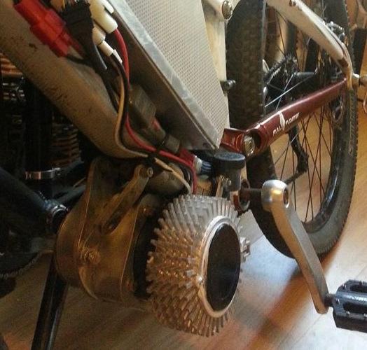
 To achieve correct alignment install shims inbetween the frame clamp and the cross brace location A on drawing to the right.")
 Next install shims between the frame clamp and main mounting")
8 Page 8 of 39 12) Also whilst tightening this bolt, adjust the stainless steel clamp rotation so the bolt is always parallel to the ground, so that it goes into the plate 90 degrees square and not at an angle. 13) Continue tightening the bolt so that it comes through the AFT bracket. At this stage check the alignment of the bracket compared to the chain wheel and make sure that it will not create a misalignment as pictured to the right. 14) To achieve correct alignment install shims inbetween the frame clamp and the cross brace location A on drawing to the right. We recommend 8mm of shims particular if you have a small circumference downtube to space the cross brace back to get more leverage angle. The more shims you put in this location the more it will PULL the bottom of the main drive plate towards the centreline of the bike 15) Next install shims between the frame clamp and main mounting plate to adjust the top alignment location B on drawing to the right. The more shims you put in this location the more it will PUSH the top of the main drive plate away from the centreline of the bike 16) Once you are happy with the shim alignment then you can finally lock in the main front frame clamp long bolt, turn it clock wise until its firm but not too hard to damage your frame. BE CAREFUL NOT TO OVERTIGHTEN frame clamp bolts as you may strip the threads Once the frame clamps bolt is tight, now you can install the final nut and thick washer provided on it, hold it firm onto the main mounting plate. The alignment of the motor freewheel should never be outwards as it will cause chain drop, it should be 100% inline for the 24v kits. For the 36v 960w and 48v 1680w kits the alignment should be angled slightly inwards 2-3mm to allow for any flex under high loads, which straighten the bracket out slightly, under full load.


9 Page 9 of 39 VERY IMPORTANT- Chain drop/broken chains If you are getting chain drops you need to diagnose what is causing it as this is not normal and it will damage chains and chainrings if you are not careful. The chain rings do have some run out and axial play. This is due to the clearances in the freewheel and is normal. But if you have excessive axial play of ~ 5 to 10mm, this could indicate = a) The cranks have not been fit onto the BB correctly b) That you have bent chain rings c) You have unequal chainring spacing. If none of the above are true and you have only 1-3mm chainring axial play, then most likely you have a derailment caused by the 3 common cases below. First you need to diagnose in which locations the chain came off as pictured here: Derail type location 1= Bike Chain derails onto crank chain wheels, This can occur if you ride on bumpy terrain and if you do not use a bike chain derailleur on the seat post tube. It s advised to install one even if you will not use it to change gears to stop these derailments. Derail type location 2= Motor Chain derails outwards feeding into motor chain wheel. This can occur if the upper chain guide is not adjusted correctly to guide the chain onto the motor freewheel as you peddle faster than the motor. Make sure the guide is aligned in the middle of the chain. Also the guide should be placed close enough to the chain that it will just not touch the chain, when the motor pulls the chain under full load. Derail type 3(Most common) = Motor Chain derails outwards on the bottom of the crank chain wheel. Most likely your motor/freewheel alignment is out and you need to preload the front of the mount bracket inwards 2-8mm from the top and bottom bolt locations or also your bottom chain guide is not centred on the chain or is too far away from the chain to help guide it. If you do not have our alignment tool you can also check with a ruler as per the picture to the right, this is the most common mistake people make; bracket is bowed out at the front. To fix it move shims to other side.
10 Page 10 of 39 Please note that when you adjust the alignment you will also affect the chain tension, so you need to go and re-adjust the chain tension to be no more than 1.2mm backed off from 100% tension. Be careful not to run more than this chain tension as you will derail and possibly break the chain and bend the mount bracket as it torques up. Also before testing with motor power make sure to try turning the cranks by hand and see if the chain feeds through easily without binding up on the freewheel, after this you can now test under full motor power for chain drop. Until you resolve the chain drop, it s a good idea to NOT put on the chain guard to make it easier to adjust the alignment. To make it easier to check the tension and alignment we have made some tools as pictured below. Once you have checked the motor to cranks alignment with our tool, or a straight edge please compare it to the pictorials on the next page to see what actions to take to fix it.

11 Page 11 of 39


 Get the chain and rag and place it over and around the middle gear on the freewheel crank assembly carefully so that all the teeth sit")
 Then get the opposite no chain side crank arm and place some lubricant inside the square hole and onto the retaining bolt.")
 Fasten both the left and right hand crank retaining bolts with a 14mm socket by holding the crank arm in the other hand.")
12 Page 12 of 39 17) Get the right hand crank arm and screw it onto the freewheel crank assembly by hand if not already done so, the finally tightening will occurs once the bike is peddled. Next put some lubricant inside the square hole of the crank arm, also get one of the provided crank arm retainer screws and apply some lubricant to the threads. Refit the crank arm on the chain side of the bike as per removal procedure. 18) Once the chain side of the bottom bracket has been aligned to the motor gear, go to the opposite side of the bike and tighten the cartridge bottom bracket retaining ring with the cartridge removal tool and the 5/16 spanner as far in as it goes tightly, (25 to 30 foot pounds of torque if you have a torque wrench). 19) Get the chain and rag and place it over and around the middle gear on the freewheel crank assembly carefully so that all the teeth sit evenly on the chain. Then slide this assembly onto the cartridge bottom bracket with the chain attached. 20) Then get the opposite no chain side crank arm and place some lubricant inside the square hole and onto the retaining bolt. Place this crank onto the bottom bracket and make sure it s 180 degrees i.e. facing the opposite side to the other crank. 21) Fasten both the left and right hand crank retaining bolts with a 14mm socket by holding the crank arm in the other hand. Fasten both sides clockwise, Push onto both side the original plastic covers. 22) Now install the motor onto the bracket making sure to align the motor drain hole facing down and back as per the red arrow below, so that if any water gets in it will run out. Tighten the 4 nuts and washers loosely to allow for chain tension adjustment later.


13 Page 13 of 39 23) Now check the alignment of the motor gear OFFSET Adjustment with the outermost gear of the freewheel and make sure if it is straight. You need to place the back of a vernier calliper or a ruler in the location of the 2 yellow markers on the drawing to the right. And measure the distance from the centre of the bike gear (blue line) to the drive plate offset. Measure for the crank gear and then repeat for the motor gear. If these are not the same then you can adjust the motor freewheel more outwards by loosening the grub screw and sliding it out. Or conversely you can adjust the Peddle crank gears further outwards by placing a bottom bracket spacer between the bottom bracket and the AFT bracket (most local bike shops will carry these). On most bicycles there is enough adjustment in the bottom bracket and motor freewheel to align the motor and crank gears. Alternatively you can use 4 washers on top of the 4 motor bolt s to move the motor and gear more central to the bike frame and away from the chain wheel, before you screw it onto the bracket. 24) The bracket has been designed with enough play in the mounting slots so that by shortening or lengthening the chain length and by adjusting the position in these slots that no additional chain tensioner is required, this gives the quietest and most efficient setup. However if you are having problems adjusting this tension or you get frequent derailments then we recommend you install the chain tensioner. To adjust the chain tension without the chain tensioner, shorten the links of the chain as required and adjust the position of the motor so that the chain is as tight as possible but does not chain bind in operation. Lift the back wheel of the ground and rotate the crank by hand to see if the chain binds or gets tight, we want it to move freely at all times. Some crank wheels have some eccentricity and hence may be tight in only one spot of their rotation, if so mark this spot and place the crank in this position and then re-tighten the motor tension at this worst case spot. 25) Using a chain breaker tool wind the long handle clockwise to drive the chain link out, now remove the excess links. 26) Now clip both ends of the shortened chain together and use the chain breaker tool to push back in the new pin to reconnect chain. Take note of the depth of other link pins and push this link in to the same depth, not too deep and not too shallow.


 First place one nut and washer on the 2 longer motor retaining bolts and tighten them firmly.")

14 Page 14 of 39 27) If required, install motor chain tensioner next. If you have the change guide upgrade skip further to that section Optional Installing chain guide upgrade. First replace the 2 motor bolts with 5mm longer ones then standard, place these longer bolts in the bolt positions shown in the photo on the right. 28) First place one nut and washer on the 2 longer motor retaining bolts and tighten them firmly. Then place the swing arm bracket and spring retaining bracket as pictured. Finally place the 2 nyloc nuts onto these 2 bolts. Loosely adjust the 2 nuts but do not tighten the nyloc nut too tight, so that the swing arm can still move as required. 29) Now check to see that chain tensioner keeps spring tension and that it also moves freely but not so loose that it has side play.

 Adjustment Method 1: Measurement Using the depth gauge of some vernier callipers or very carefully with a ruler, you can place it on the edge of the bracket flat section( see picture on the right)")
15 Page 15 of 39 30) Optional Installing chain guide upgrade. Adjusting the chain tension Let the motor fall back towards the cranks so that it it s in the most slack chain position. Then place the chain around outer crank sprocket and around the motor freewheel. Then tension the chain by hand and try and find the shortest link you can join it back together. Do not force the chain together, this will give you a slightly loose fit and then the bracket will give you just enough play to adjust up for the rest of the slack. A) Adjustment Method 1: Measurement Using the depth gauge of some vernier callipers or very carefully with a ruler, you can place it on the edge of the bracket flat section( see picture on the right) and then measure how far away the motor is from the end of the bracket. Make sure the chain is tensioned evenly on both sides as you won t be able to get the full extension if one side of the chain is tight due the teeth location. This point is 100% tensioned baseline. Then what you can do is slide the motor back about 1.1 to 1.25mm of slack from 100% tension. Important: Now tighten the 4 motor nuts and washers one by one with a 10mm spanner, we recommend that you hold the allen key bolt from the back with an allen key, so that when you do a final lockup it does not undo the bolt and possibly break the gearbox to motor seal. ( for titanium bolt hardware option please make sure not to overtighten and torque to spec. ) We find this gives a best amount of chain slack- not too loose or not too tight. B) Adjustment Method 2: With motor tensioner and 1.2mm spacer Place a 1.2mm spacer inside the gap between the gearbox body and the motor tensioner as pictured. Back off Nut 2 completely so that it allows you to freely rotate Nut 1. You can remove it completely if needed. Tighten Nut 1 slowly until it pulls the motor away from the cranks and tightens up the chains nice and firm. There should be no slack in the motor chain at this point. Then tighten Nut 2 against the standoff post, so that the position of the chain tensioner becomes locked in this position.

 This method is the preferred method and it makes it very easy to make sure you have the exact correct motor chain tension every time.")
16 Page 16 of 39 Remove the 1.2mm spacer, now slide back towards the cranks the motor/gearbox assembly in its 4 bolt slots so that it sits flush against the motor tensioner. Important: Now tighten the 4 motor nuts and washers one by one with a 10mm spanner, we recommend that you hold the allen key bolt from the back with an allen key, so that when you do a final lockup it does not undo the bolt and possibly break the gearbox to motor seal. ( for titanium bolt hardware option please make sure not to overtighten and torque to spec. ) This method is the preferred method and it makes it very easy to make sure you have the exact correct motor chain tension every time. 31) Adjusting chain guide, now that you have adjusted the motor and chain tension you can now adjust the chain guide location. To do this place the chain guide in its slot with the inner bolt loosely next to the aluminium bracket so that it can slide. Move it towards the chain and using your thumb push the chain down as tight as you can at the location of the chain guide, so that it sits right next to the chain but does not touch it. It should have 1.5-2mm clearance around both sides and outside of the chain at this point. After adjustment pull the chain outwards to see how close the chain gets to the guides on full deflexion, it should just touch in this situation. Adjust washers and location accordingly. 32) Check adjustment, there should be no excessive drag on the peddles from the motor chain friction. If the chain is too tight the chain will be noisy and your no load current will be high. You can check the no load current without the bicycle chain and just the motor chain to see if you have the chain too tight. If the chain is too loose you will get a lot of chain droop and chain flex and it will rub on the chain guide too often and also have a risk of derailments. The motor chain should not touch the chain guide in normal operation or often, when it is working correctly you will only hear a slight ticking sound when you do full power gear changes at high load or when going around sharp corners as the chain rubs on the sides of the chain guide. 33) OPTIONAL EMAX stage 2 oil reservoir, if your kit has the optional stage 2 oil reservoir, remove the rubber liner inside the lid after unpacking your kit. Also their maybe some tape over the slow release breather vent. These are placed during transportation to stop oil leaks, please remove them for normal operation, to allow oil to flow into and out of the gearbox without air locks. You should now install just the oil reservoir plastic cap and not the rubber lid seal.
 For the 24v 200w and 500w now install wiring.")
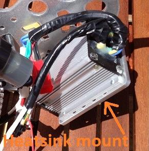
 For the 24v 650w, 36v and 48v kits only, now install Kelly controller wiring, to get access to wires remove the 2 screws holding the controller cover pictured to the right.")
17 Page 17 of 39 You can re-apply these two items if you will place the bike upside down for a long period of time to stop oil leaks when upside down. You should also place a cable tie to hold the oil hose next to the tensioner bolt so it doesn t rub on the chain 34) For the 24v 200w and 500w now install wiring. Plug the red and black main power cable together and then the multi pin plug. 35) For the 24v 650w, 36v and 48v kits only, now install Kelly controller wiring, to get access to wires remove the 2 screws holding the controller cover pictured to the right. 36) Plug the red and black main power cable together, and make sure to also plug the red bullet plug controller enable plug as well to positive battery voltage. Now plug the 2 pin and Single pin phase wires together. And finally plug the 3 pin and 2 pin throttle plugs together. Note- all plugs above only go in one way and one location. If not already applied, apply silicon sealant around the cable entry points of the controller. If you will be riding in very wet conditions or Snow we also advise to silicon over the top of the existing sealant over all screws on and side flanges of the controller. Also for the Rs232 plug on the controller, we recommend to install our optional controller mud guard.


 **SAFETY** Is Very Important: Please check that all steps have been followed and if you are")
18 Page 18 of 39 Note the location of the cable layout under the mud guard so that all the cable joins are under the mud guard. And also on the other side of the bracket note where the power cable should be cable tied, so it doesn t rub on the chainrings. Note how the controller should look when reinstalled, don t install it just yet, do so once you have done all your tests and are happy the kit is working. 37) Turn bicycle over onto its wheels and put on stand. 38) **SAFETY** Is Very Important: Please check that all steps have been followed and if you are unsure please contact us or your local bicycle shop to ensure the kit is installed safely onto your bicycle. For your own safety AT ALL TIMES KEEP hands and fingers away from the chains or moving parts of the bicycle when operating.
 Install rear rack as per the installation instructions of the rack manufacturer; install the battery pack as per their respective instructions.")

19 Page 19 of Install optional Kickstand Install the optional kickstand as pictured here: 8. Install rear rack and battery pack (Optional) Install rear rack as per the installation instructions of the rack manufacturer; install the battery pack as per their respective instructions. Connect battery pack to motor harness red plug 9. Adjust the bicycles gears and test ride Now that the kit has been installed and bike is able to be ridden with NO ELECTRIC POWER ASSIST, test ride the bicycle by peddling and by changing through all the gears and do a fine adjustment of the middle derailleur on the bicycle. Check to see if all gear systems are working and the chains move freely, inline and do not derail. If you are having problems with this your local bicycle shop will be able to help you do this. 10. Test electronics unloaded (Optional) Now that the kit and battery have been installed and connected. Put a 2cm thick wooden block spacer under the bicycle stand or any other suitable stand that will allow the rear wheels of the bicycle to rotate freely just off the ground and the bicycle will sit safely on it and not topple over.

20 Page 20 of 39 Turn the ON switch on the throttle. Turn the throttle slightly and observe if the motor turns the rear wheel successfully and freely with no binding or noises. Observe if the gear system of the bicycle is working correctly. If not make adjustments accordingly. 11. Final electric assisted test ride and finish installation Test ride at slow speeds and low throttle positions. Change through all the low and high gears to see if everything is operating correctly and there is no gear binding or derailing, also check that all cables and loose items are firmly cabled tied and away from all rotating assemblies. And finally if all is ok you can go for a longer test ride at higher speeds. Once this is done and no furthers adjustment are required, you can now finalise the wiring, for kits with the Kelly controller in the low mount position, if you will be riding in very wet conditions. We recommend that you tape over with electrical tape ALL of the electrical connections as pictured to the right to keep water out of the terminals.. After all testing is successful and you confirm there is no chain drop you can now install the Chain guard. Remove only the 2 nuts of the motor that match up with the locations pictured to the right, do not loosen all 4 motor nuts as it will affect your chain tension. You can ENJOY the new experience and freedom of an AFT electric bicycle.


21 Page 21 of Usage and Maintenance instructions Usage: When riding a crank drive ebike it is VERY IMPORTANT: That you wear tight fitting pants/shorts on your right side leg or tie them up in your socks with elastic. Both the crank and motor have chain guards but there is still a risk if you wear loose clothing around your leg that they could be drawn into the chain, so please be careful. The right hand twist throttle controls the amount of power from the motor, the further back you twist it the more power you will have. You do not have to peddle to get power from the motor as in some other systems. The twist throttle also has an on/off switch that turns the motor assistance on/off. When the bike is sitting for a long time please make sure to switch this off to not drain the battery pack unexpectedly. The twist throttle has a 3 colour led indicator, Green indicates fully 100% charged, Orange is nearly empty 20% charged and Red is battery will soon be flat 5% charge. When you see a flashing red led this indicates a low voltage cut-out situation or throttle wires connection fault. This happens when the battery is completely flat or faulty. This may also occur near the end of a battery charge when the battery is nearly flat and you are going up steep hills or high load situation. In this case we advise that you should reduce the throttle and hence load on the motor to reduce voltage sag on the battery and hence red light should stay solid and not flash. Gear shifting: Like all bicycles we do not recommend that you shift gears on the front derailleur when the motor is operating at high speed or high torque/load situations. VERY IMPORTANT: You should only change the front gears of the bicycle when peddling slowly by foot. This is due to a risk of derailing and hence risk of damage to the crank/ freewheel /bicycle and the rider slipping forward on derailment. The rear derailleur is a lot more tolerant of changing gears under load, however to maximise the life of the bicycles gear system and to reduce shock loads it is recommended to reduce the throttle to minimise the load and wear on the gear changes using the rear derailleur as well.
22 Page 22 of 39 Chains: Every kms if the chains appear dry, we recommend that you apply a high quality anti dust lubricant to both chains, to maximise the life and minimise the wear on the bicycles chains. Every 1500 kms we recommend the chain is removed from the bicycle and given a thorough clean in a solvent or citric acid cleaner to remove all ingrained dirt and wear particles. For 24v to 36v kits we recommend that every 4000 kms a chain stretch gauge is to check if the chain is still serviceable. For 48v kits we recommend that every 2000 kms a chain stretch gauge is to check if the chain is still serviceable. Replace the chain as required by the chain stretch gauge. Water: The bike kit is water resistant to light intermittent rain and not water proof, if you will be riding in heavy rain often or through deep puddles we recommend that you apply a clear silicon sealant around the motor housing flange and the motor body but please make sure to leave the drain hole clear of sealant. Also for the twist grip throttle a bead of silicon can be applied on the inside surface of the clear window to housing once it has been unscrewed. Once the cover is reinstalled then some sealant can be applied on the outside cover of the housing. Periodically check all motor seals on flange joins are intact and that throttle housing is intact to ensure there is no water ingress into the electronics. Also please ensure the motor drain hole is always pointed downwards and not blocked up with debris. This is to allow any water ingress to drain out of the motor. Also check the controller wiring plugs to make sure that any electrical tape is still in place over the connections to stop any water ingress. Motor and bracket alignment: Check the alignment and tension of the motor retaining bracket bolts and the 2 stainless frame clamp bolts on regular intervals to make sure nothing has come loose or has moved out of alignment, this is very unlikely with our PRO kit mounting system. Chain tension and alignment Check the tension and alignment the motor chain and to make sure it hasn t loosened enough to rub on the chain guide. This is to make sure there has been no movement of the motor brackets that causes unnecessary load and wear on the slack/unaligned or loose chains. You can also use our new alignment tool to check this more accurately as it sits flat against the motor and crank freewheels. Also our new chain tension shim makes it easy to check the tension with the chain on.
23 Page 23 of 39 EMAX chain guides Check and adjust the alignment of EMAX chain guides to maintain it should have 1.5-2mm clearance around both sides and outside of the chain in its natural unloaded position. This is to make sure the chain guides will only touch in extreme movement situations such as high loads when the chain stretches or when going around sharp corners and bike is leaning over. Freewheels: Every 1000 kms or any time the freewheel coasting sounds loud and gritty you should lubricate: 1) The back wheel freewheel, 2) Peddle crank freewheel and 3) Motor freewheel. To lubricate, put the bike 45 degrees on its side and place in a few drops of light to medium weight oil into the joins in the freewheel inner to outer ring. Then lift or chock up back wheel off the ground and try to rotate the motor, cranks slowly to help the oil get into the freewheel bearings. Stop and let the wheel coast, then press the throttle on/off in a similar way a few times. Repeat again with a few more drops of oil until you hear a change in the sound of the clicking pawls as the oil is dragged in to the freewheels, they will sound quieter and smoother. For severe off-road dirt use if there is lots of grit around the freewheel it may have penetrated inside the bearing, in this situation we recommend that you first flush out the contaminants with a high pressure air/kerosene spray or wd40 mix. After the freewheel has been cleaned then you add the lubricating oil as per above instructions.


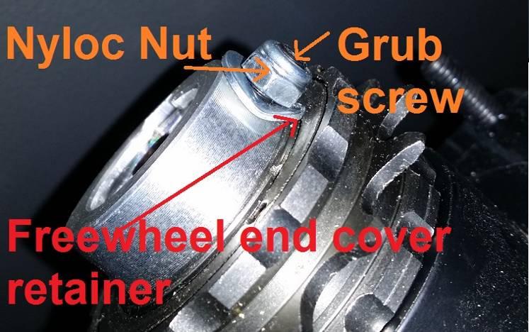
24 Page 24 of 39 Gearbox: Grease lubricated: To ensure longevity of the motor gearbox grease, it is recommended that it is removed and that the teeth and grease is inspected for visible wear and damage every 2000 km s or if the gearbox gets noisy. Check to see if the grease has not dried out as per picture on the right and is visible on all the gears. You can send us photos to inspect it for you. Nothing further maybe required if the grease looks sound however in some high power/high mileage situations it may need regular re-greasing with the correct grease. AFT EMAX oil lubricated For high mileage bikes or with motor power at or above 960w we highly recommend our grease to oil conversion upgrade to improve the longevity of the planetary teeth. For oil lubricated gearboxes we recommend the oil level is checked often to not run dry in case of leakages. If you notice the gearbox is making an unusual high pitched or scraping sound then this could indicate there is no oil in the gearbox and it must be topped up. Stage 2 oil conversion Oil top up: To top up the oil just add oil to the reservoir and reinstall the expansion cap. If you have had significant oil loss, to get the oil back into the gearbox quickly, you may need to loosen the top breather plug. To do this take the chain off and push the motor in the furthest position away from the cranks. In this position the top breather plug should be visible. Next remove the oil line from the gearbox side fitting and allow oil to bleed out all the air in the oil sight tube. Once this is done reinstall clear oil tube and allow oil to gravity feed into the gearbox. After about 30minutes time when the oil level has equalised in the gearbox, the top breather can now be re-installed and resealed. Lastly the oil reservoir cap can be reinstalled. Flush and purge of gearbox oil to extend the life, to maintain the 1 year warranty on the gearbox the oil should be flushed and purged every 2500 kms miles. To do this the best time is after a long ride so the gearbox oil is still hot. Remove the motor chain and slide the motor all the way forwards to allow access to the top breather plug. Lock the motor in this position. Now remove the top slow release breather and also remove the small piece of foam in the bottom of the hole. Now remove the bottom clear oil reservoir hose/ brass hose barb or drain plug depending on what is installed. Leave the bike face down on the chain side and put a small bucket underneath the gearbox area and let it drain out overnight. You should get about 25-35ml of fluid out of the gearbox and 15ml from the reservoir. Then do the reverse process to re-install, Make sure to use a thread sealant on the brass hose barb threads. To refill with oil you can use our refill purge kit with the syringe or you can also slowly fill the oil from the oil reservoir (make sure the top breather vent is still open). Check that oil is flowing out of the reservoir and into the gearbox and that there is no airlock in the clear hose. It takes 30-35ml to fill up the gearbox and then also 15ml of oil into the reservoir. Once there is oil in the gearbox then you can install the top breather foam plug and grub screw and lastly install the chain.

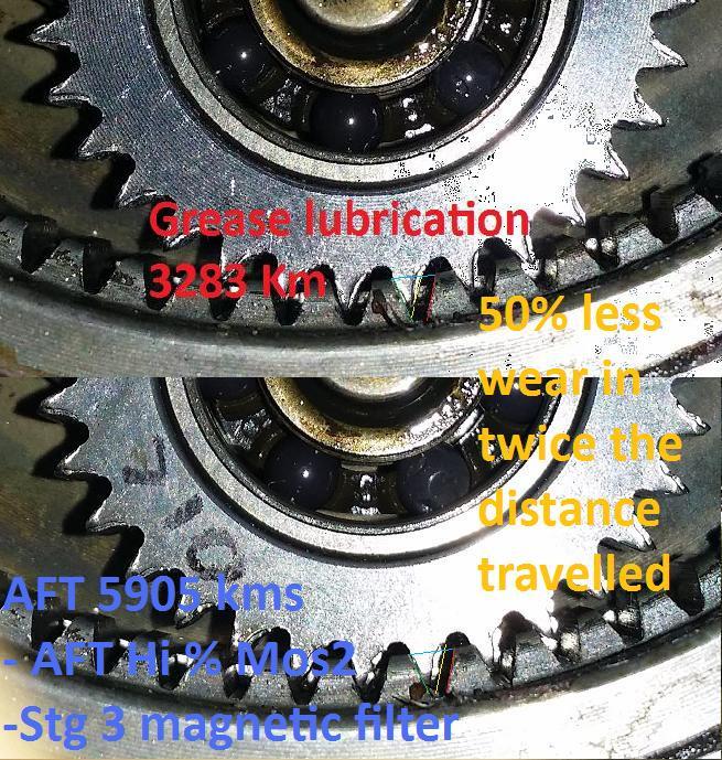
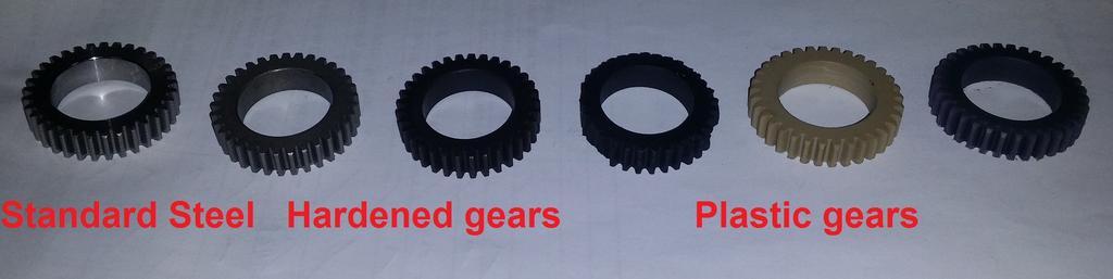
25 Page 25 of 39 Planetary gear end of life replacement The gearbox should be removed and teeth inspected for excessive wear every 6,500 Kms ( 4000 miles). The planetary gears are a wearing part that needs to be serviced or replaced when worn out. If the teeth look as pointy as in the picture to the right, they need to be replaced otherwise the teeth can break off as pictured in orange and then possibly cause consequential damage to the outer ring and motor pinion gear. The life of the gears can vary significantly from as low as km with grease and in our Mos2 Nano oil from 6,500km (4000miles) to 12,000km (8000 miles) depending on the motor power, peddling assistance, load on the bike and frequency of oil changes. Additionally our Optional stage 3 magnet filter will also increase the life of the gearbox by filtering out the wear particles from the oil. On every gearbox removal and visual inspection you can just wipe over the magnets with a rag to remove the metal particles from the magnets, be careful to not dislodge them, or if they do dislodge can just put them back in the same pattern they were removed. New For high load high power kits above 3kw we have new hardened Planet gears and hardened rotor gears available- See photos below in Upgrades section. Please contact us for a replacement planetary gear or if you have any question at: AFT_ebike@hotmail.com For our latest upgrades and pricing please see our website:
26 Page 26 of Installation Check sheet Section read and completed Tick if completed 1. Safety Educational Requirements of Installer and Public Liability Disclaimer Tools/ Consumables required Parts list Diagram and Check sheet Estimated Time of Installation Procedure Install rear rack and battery pack (Optional) Adjust the bicycles gears and test ride Test electronics unloaded ( Optional ) Final electric assisted test ride and finish installation Usage and Maintenance instructions Installation Check sheet Upgrades ( See next page)... **SAFETY** Is Very Important: Please check that all steps have been followed and if you are unsure please contact us or your local bicycle shop to ensure the kit is installed safely onto your bicycle. For your own safety AT ALL TIMES KEEP hands and fingers away from the chains or moving parts of the bicycle when operating.


27 Page 27 of Upgrades Stage 1= Gearbox grease to oil conversion Stage 2 = External oil reservoir and sight tube High temp high RPM low drag oil seal Stage 3= Gearbox Oil filer magnet ring and oil reservoir magnet Chain tensioner to chain guide conversion with alignment of freewheel cranks to BB 104, 110, 130 BCD chainring adaptors with extended chain ring nuts and spacers ACS crossfire freewheel


28 Page 28 of 39 Ceramic motor bearings EXTRA HDUTY Dual Solid Steel 48T chain wheels and EXCESS PRO FREEWHEEL Ceramic gearbox bearings Custom low friction gearbox oil with Nano Particle Mos2

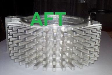
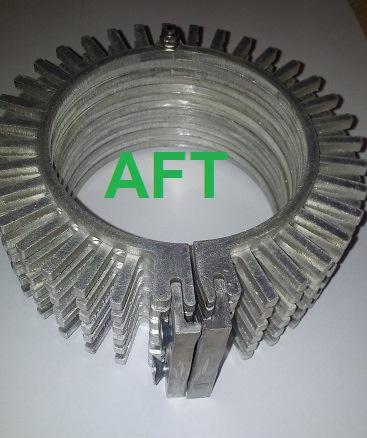
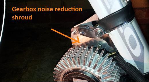
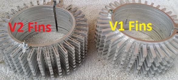
29 Page 29 of 39 NEW High performance laser cut cooling fins NEW Gearbox noise reduction shroud


30 Page 30 of 39 NEW Noise reduction chain guard Motor tensioner for people who track stand at traffic lights and optional on 48v to stop motor sliding back. EXTRA HDUTY 6mm Folded bracket suits 48v to 60V motors And 100mm bottom bracket 12mm welded offsetting adaptor mod.


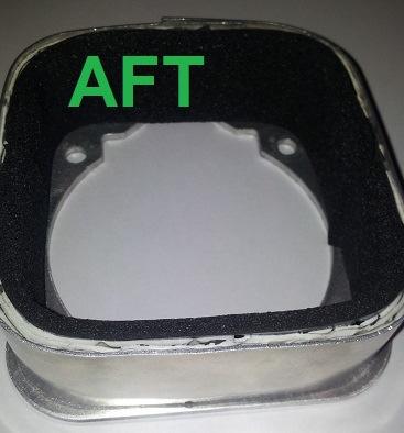
31 Page 31 of 39 EXTRA HDUTY ISIS bottom brackets Polymorph DIY moulds to make a 100% tight fit to any bike tube profile such as square frame Controller and cable water splash/mud guard

32 Page 32 of 39

33 Page 33 of 39


34 THE AFT Advantage New AFT ultimate kits Page 34 of 39


35 Page 35 of 39 10,000 kms of rigorous testing and ongoing... currently at 20,000 kms


36 Page 36 of 39 All our EMAX oil converted kits are leak down tested to ensure there is no oil leaks. And every EMAX motor has a full throttle no load test to look for any inconsistencies and to be certain each motor will have the same maximum efficiency
37 Page 37 of 39 COMINGS SOON Coming soon: Free wheel dirt shield and oil retention seal (Optional) Coming soon: 54T custom chain wheel with chain guard to suit direct bolt up to 5 BOLT freewheels, as well as 104 and 130 BCD chain ring hole locations. Coming soon: Custom Scott Oiler UBS solution automatic dual chain oiler for bike and motor chain.


38 Page 38 of 39


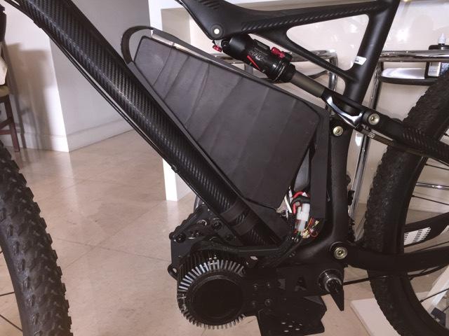
39 Page 39 of 39 Carbon frame with left side clamp
Santa Fe Cycles Assembly Guide Introduction
 Santa Fe Cycles Assembly Guide Introduction Congratulations on your purchase of your new Santa Fe bicycle. You have purchased a bicycle that has many features and qualities. Please take a few minutes and
HOME ASSEMBLY INSTRUCTIONS
 HOME ASSEMBLY INSTRUCTIONS This Papillionaire Bicycle now belongs to you. It will take you to work, wait patiently outside your local cafe, and carry your groceries home. This is the start of your long-term
Lectric Cycles Mid-Drive Electric Motor Installation
 Lectric Cycles Mid-Drive Electric Motor Installation This write-up describes the installation of a Lectric Cycles electric motor. The model is the e-rad Mid-Drive 750 Watt conversion kit, installed on
Drive Belt Instructions
 Drive Belt Safety Do not roll, pry, twist, invert or bend the belt back on itself. Do not zip tie the belt. The acceptable temperature range for your belt drive is -53 C to 85 C. Do not lubricate the belt
Changing Out the Rear Hub and Sprocket on a 2012 Morgan Three Wheeler Calum Fraser 17/07/2015
 Intro The early Three Wheelers had the rear sprocket in a stepped arrangement relative to the front sprocket with the belt overhanging the sprocket on the outside face. While this is probably less of a
POWER ASSISTED BICYCLES OWNERS MANUAL
 POWER ASSISTED BICYCLES OWNERS MANUAL WE HAVE INCLUDED A BICYCLE OWNER S MANUAL WHICH YOU SHOULD REFER TO FOR ALL GENERAL CYCLE MAINTENANCE. CONTENTS Page. 3 Unpacking. Page. 3-4 Easy steps to get started.
Parts List. 7. Handlebars 8. Grips 9. Handlebar Stem 10. Front Brake 11. Front Wheel 12. Crank 13. Chain
 Woodworm Cruise Parts List 1. Free Wheel with Rear Hub 2. Fenders 3. Fender Stay 4. Quick Release 5. Saddle 6. Seat Post 7. Handlebars 8. Grips 9. Handlebar Stem 10. Front Brake 11. Front Wheel 12. Crank
DM-RD (English) Dealer s Manual. ROAD Rear Derailleur RD-9000 RD-6800 RD-5800 RD-4700
 Dealer s Manual. ROAD Rear Derailleur RD-9000 RD-6800 RD-5800 RD-4700") (English) DM-RD0003-09 ROAD Rear Derailleur Dealer s Manual RD-9000 RD-6800 RD-5800 RD-4700 CONTENTS IMPORTANT NOTICE...3 TO ENSURE SAFETY...4 LIST OF TOOLS TO BE USED...6 INSTALLATION...8 Chain length...
(English) DM-RD0003-09 ROAD Rear Derailleur Dealer s Manual RD-9000 RD-6800 RD-5800 RD-4700 CONTENTS IMPORTANT NOTICE...3 TO ENSURE SAFETY...4 LIST OF TOOLS TO BE USED...6 INSTALLATION...8 Chain length...
TECH SHEET ORANGE PIVOT TOOL INSTRUCTIONS
 page 1 ORANGE PIVOT TOOL INSTRUCTIONS This is a guide of how to change the pivot bearings on an Orange frame with a bore style pivot axle. 4 8 Bore Type Pivot Axle Horiz-Hold Type Pivot Axle Please read
Have questions? Chat with us live at raleighusa.com or call us at , 8am 5pm PST
 1 2 Have questions? Chat with us live at raleighusa.com or call us at 1-800-251-8435, 8am 5pm PST The bicycle you have purchased is a complex piece of equipment that must be properly assembled and maintained
Have questions? Chat with us live at raleighusa.com or call us at , 8am 5pm PST
 1 2 Have questions? Chat with us live at raleighusa.com or call us at 1-800-251-8435, 8am 5pm PST The bicycle you have purchased is a complex piece of equipment that must be properly assembled and maintained
USER GUIDE TO POWER ASSISTED BIKES
 USER GUIDE TO POWER ASSISTED BIKES 1 PAGE CONTENTS Page. 3 Unpacking Page. 3-4 Easy steps to get started Page. 5 General Assembly Instructions Page. 6 Aligning H/Bars, Page. 7 Tightening pedals onto Crank
Assembly, Fitting, Care & Maintenance
 Assembly, Fitting, Care & Maintenance Assembly 1.1 Remove All Parts and Tools from Packaging 1.2 Part and Tools required for assembly 1.3 Check Foot & Leg Assembly 1.4 Adjust Upper-Leg-Support (ULS) Height
2019 MADONE ASSEMBLY MANUAL
 2019 MADONE ASSEMBLY MANUAL 2019 MADONE Rim brakes and Di2 drivetrain Rim brakes and mechanical drivetrain Disc brakes and Di2 drivetrain Disc brakes and mechanical drivetrain TABLE OF CONTENTS Common
BICYCLE ASSEMBLY INSTRUCTIONS. dutchcycles.com.au. Distribution Centre
 BICYCLE ASSEMBLY INSTRUCTIONS dutchcycles.com.au Distribution Centre Shed 68, 400-422 Somerville Road, Tottenham, VIC 3012 email: service@dutchcycles.com.au BICYCLE COMPONENTS KEY INTRODUCTION CONGRATULATIONS
Folding Dual Suspension MTB. Instruction Manual
 Folding Dual Suspension MTB Instruction Manual Introduction The Stowabike Folding MTB has been made to last and with proper maintenance, it will give you years of enjoyable rides and journeys. The following
Troubleshooting Guide
 Troubleshooting Guide This troubleshooting guide outlines quick fixes to the most common technical questions about the ElliptiGO. If the problem persists or you feel uncomfortable performing these actions,
Congratulations on your purchase of a JC Series Performer trike! The Performer JC Series is designed for everything from touring to commuting and
 Congratulations on your purchase of a JC Series Performer trike! The Performer JC Series is designed for everything from touring to commuting and shopping in the city. The JC Series frames are made of
Special instruction of installation for SAINT FH-M800/RD-M800 and FH-M805/RD-M805
 Technical Service Instructions SI-5VB0E t RD-M805 / RD-M800 Rear derailleur Special instruction of installation for SAINT FH-M800/RD-M800 and FH-M805/RD-M805 A hub axle is an essential component for the
E-trike Li Assembly Guide
 PREPARATION 1. Read this assembly manual BEFORE commencing assembly. 2. Carefully remove all the components and packaged hardware from the shipping boxes. 3. Unpack the contents of the large double box
DM-MBRD (English) Dealer's Manual. ROAD MTB Trekking. City Touring/ Comfort Bike. Rear Derailleur SLX RD-M7000 DEORE RD-M6000
 Dealer's Manual. ROAD MTB Trekking. City Touring/ Comfort Bike. Rear Derailleur SLX RD-M7000 DEORE RD-M6000") (English) DM-MBRD001-04 Dealer's Manual ROAD MTB Trekking City Touring/ Comfort Bike URBAN SPORT E-BIKE Rear Derailleur SLX RD-M7000 DEORE RD-M6000 CONTENTS IMPORTANT NOTICE... 3 TO ENSURE SAFETY... 4
(English) DM-MBRD001-04 Dealer's Manual ROAD MTB Trekking City Touring/ Comfort Bike URBAN SPORT E-BIKE Rear Derailleur SLX RD-M7000 DEORE RD-M6000 CONTENTS IMPORTANT NOTICE... 3 TO ENSURE SAFETY... 4
DM-RARD (English) Dealer's Manual. ROAD MTB Trekking. City Touring/ Comfort Bike. Rear Derailleur DURA-ACE RD-R9100 ULTEGRA RD-R8000
 Dealer's Manual. ROAD MTB Trekking. City Touring/ Comfort Bike. Rear Derailleur DURA-ACE RD-R9100 ULTEGRA RD-R8000") (English) DM-RARD001-03 Dealer's Manual ROAD MTB Trekking City Touring/ Comfort Bike URBAN SPORT E-BIKE Rear Derailleur DURA-ACE RD-R9100 ULTEGRA RD-R8000 CONTENTS IMPORTANT NOTICE... 3 TO ENSURE SAFETY...
(English) DM-RARD001-03 Dealer's Manual ROAD MTB Trekking City Touring/ Comfort Bike URBAN SPORT E-BIKE Rear Derailleur DURA-ACE RD-R9100 ULTEGRA RD-R8000 CONTENTS IMPORTANT NOTICE... 3 TO ENSURE SAFETY...
CRUZBIKE Quest 2.0 Assembly
 CRUZBIKE Quest 2.0 Assembly CRUZBIKE Quest 2.0 Assembly... 1 General notes on assembly... 2 Un box and evaluate the frame and major parts... 2 Unfold the rear swing arm and arrange the frame... 3 Rear
DM-MARD (English) Dealer's Manual. ROAD MTB Trekking. City Touring/ Comfort Bike REAR DERAILLEUR XTR RD-M9100 RD-M9120
 Dealer's Manual. ROAD MTB Trekking. City Touring/ Comfort Bike REAR DERAILLEUR XTR RD-M9100 RD-M9120") (English) DM-MARD001-00 Dealer's Manual ROAD MTB Trekking City Touring/ Comfort Bike URBAN SPORT E-BIKE REAR DERAILLEUR XTR RD-M9100 RD-M9120 CONTENTS CONTENTS...2 IMPORTANT NOTICE...3 TO ENSURE SAFETY...4
(English) DM-MARD001-00 Dealer's Manual ROAD MTB Trekking City Touring/ Comfort Bike URBAN SPORT E-BIKE REAR DERAILLEUR XTR RD-M9100 RD-M9120 CONTENTS CONTENTS...2 IMPORTANT NOTICE...3 TO ENSURE SAFETY...4
SANTANA STOWAWAY TANDEM WITH AIRLINER SAFECASE AND FTS FOAM TRAY SYSTEM ASSEMBLY AND DISASSEMBLY
 SANTANA STOWAWAY TANDEM WITH AIRLINER SAFECASE AND FTS FOAM TRAY SYSTEM ASSEMBLY AND DISASSEMBLY Congratulations! You are now the proud owner of the world s most travel-ready, performance tandem. The following
9-speed super narrow. chain such as. CN-7701 / CN-HG93 8- / 7- / 6-speed narrow. chain such as CN-HG50 / CN-IG51
 - Technical Service Instructions SI-5VH0B t RD-M600 Rear derailleur General Safety Information WARNING The ST-M600 DUAL CONTROL lever is used for both gear shifting and braking operations. Make sure that
Thumb Shifter Plus Thumb Shifter
 (English) DM-SL0004-01 Dealer's Manual Thumb Shifter Plus Thumb Shifter Thumb Shifter Plus SL-FT55 SL-TX50 SL-TX30 Thumb Shifter SL-TZ20 IMPORTANT NOTICE This dealer's manual is intended primarily for
We strongly recommend watching our video tutorial for the easiest installation process.
 Introduction We strongly recommend watching our video tutorial for the easiest installation process. GTRO is dedicated for all non-sports bicycles. Please, remember it has not been tested for heavy-duty
BOTTOM BRACKET BEARINGS
 BOTTOM BRACKET BEARINGS This basic tutorial will demonstrate the workings of a typical 3 piece bottom bracket, showing the removal and installation of the various components that make up the bearing system.
comfort without compromising on performance and to fit your various needs on touring,
 Congratulations on your purchase of Goal-26X. Goal-26X is made to enhance comfort without compromising on performance and to fit your various needs on touring, shopping and communicating. Let s have fun
ASSEMBLY GUIDE AROUND THE BLOCK - 1, 3, 7, & 21 SPEED SIXTHREEZERO
 ASSEMBLY GUIDE AROUND THE BLOCK - 1, 3, 7, & 21 SPEED SIXTHREEZERO OUR COMMITMENT We want you to love your bike as much as we do. If you run into any issues, no matter how small, let us know and we ll
Troyer s Gourd Rack 8 unit F R H O P
 B E A D I M-N L Vertical Parts F R H O P Horizontal Parts C G J Updated 11/16 Parts List A: Top of Pole B: Bottom of Pole C: 48 Ground Stake D: Top Perch rods 48 long E: Hub F: Rope Winder w/ attached
FRONT DERAILLEUR - CURRENT RANGE
 FRONT DERAILLEUR - CURRENT RANGE (since 2015) (since 2018) (since 2017) (since 2018) WARNING! This technical manual is intended for use by professional mechanics. Anyone who is not a qualified professional
Assembly Tools. Assembly will take 1-2 hours
 Assembly Tools Included in your parts box: Pedals Quick release skewer Reflectors (if not already installed) Toolkit (4+5mm combo Allen wrench, 13+15mm combo open-end wrench) Helpful Tools: Scissors (for
Contents. Stainless Steel Side Block. 1.1 Separating the Side Block. Stainless Steel Side Block Reassembly of. Assembly from the Helmet Shell
 Separating the Side Block Assembly from the Helmet Shell Contents SSB-1 SSB-3 SSB-5 SSB-5 SSB-7 1.1 Separating the Side Block Assembly from the Helmet Shell 1.2 Side Block Assembly Replacement 1.3 Defogger
Rear Drive System SERVICE INSTRUCTION. Specifications SI-R670B
 - SERVICE INSTRUCTION SI-R670B t Rear Drive System Before use, read these instructions carefully, and follow them for correct use. In order to realize the best performance, we recommend that the following
LIQUIP DRYBREAK COUPLER. API800 Series MAINTENANCE INSTRUCTIONS
 LIQUIP DRYBREAK COUPLER API800 Series MAINTENANCE INSTRUCTIONS API LOADING COUPLER TO API RP1004 June 2015 Issue: F M:\Product-Info\API8xx\6-Service-Maintenance\API800 MAINTENANCE INSTRUCTIONS 40183.doc
Have questions? Chat with us live at raleighusa.com or call us at , 8am 5pm PST
 1 2 Have questions? Chat with us live at raleighusa.com or call us at 1-800-251-8435, 8am 5pm PST The bicycle you have purchased is a complex piece of equipment that must be properly assembled and maintained
TABLE OF CONTENTS FRAME FEATURES INTRODUCTION
 S3 DISC MANUAL TABLE OF CONTENTS Introduction...1 Frame Features...2 Fork Preparation...3 Small Parts...5 Frame Preparation...6 Brake Housing Installation...7 Mechanical Cable Routing...9 Electric Cable
model - CYPRESS DX W
 Contents model - CYPRESS DX W Maintenenace manual Read and Save these instructions Welcome Contents 1 Preparing Nothing makes us happier than seeing people out riding bikes. For over thirty years Giant
TRAILMATE METEOR ASSEMBLY MANUAL
 TRAILMATE METEOR ASSEMBLY MANUAL (DISC BRAKE VERSION) The Trailmate Meteor recumbent has been designed for easy assembly. This means more time to enjoy the smooth ride with single speed, 3 speed coaster
Final Assembly Instructions Bikes with Quill Stems
 Final Assembly Instructions Bikes with Quill Stems Thank you for buying your new bicycle from L.L.Bean. Read these instructions carefully before beginning the final assembly. Prior to shipping, our expert
Trike-Bike Assembly Manual
 Be sure to check our website for more instruction details, videos and photographs as well as a complete listing of each Nut and Bolt for the Trike Bike. www.trike-bike.com.au Go to the page marked ASSEMBLY
Front derailleur. Dealer's Manual SORA FD-R3000 FD-R3030 CLARIS FD-R2000 FD-R2030. ROAD MTB Trekking. City Touring/ Comfort Bike DM-RBFD001-01
 (English) DM-RBFD001-01 Dealer's Manual ROAD MTB Trekking City Touring/ Comfort Bike URBAN SPORT E-BIKE Front derailleur SORA FD-R3000 FD-R3030 CLARIS FD-R2000 FD-R2030 CONTENTS IMPORTANT NOTICE... 3 TO
LIQUIP DRYBREAK COUPLER. LYNX Series MAINTENANCE INSTRUCTIONS
 LIQUIP DRYBREAK COUPLER LYNX Series MAINTENANCE INSTRUCTIONS API LOADING COUPLER TO API RP1004 February 2016 Issue: DRAFT A Issue: DRAFT - A 02/01/16 Page 1 CONTENTS LYNX Series Datasheet... 3 LYNX Series
Shifting Lever. Dealer's Manual. RAPIDFIRE Plus SL-M2000 SL-M3010 SL-M4010. Thumb Shifter SL-TZ500. ROAD MTB Trekking. City Touring/ Comfort Bike
 (English) DM-MDSL001-01 Dealer's Manual ROAD MTB Trekking City Touring/ Comfort Bike URBAN SPORT E-BIKE Shifting Lever RAPIDFIRE Plus SL-M2000 SL-M3010 SL-M4010 Thumb Shifter SL-TZ500 CONTENTS IMPORTANT
FRAME FEATURES TABLE OF CONTENTS INTRODUCTION. A guide to your Cervélo C Series frame.
 C SERIES MANUAL TABLE OF CONTENTS Introduction...1 Frame Features...2 Fork Preparation...3 Small Parts...5 Frame Preparation...6 Brake Housing Installation...7 Mechanical Cable Routing...9 Electric Cable
7130 Lancer Rear Drive Magnetic Commercial Indoor Cycling Bike
 7130 Lancer Rear Drive Magnetic Commercial Indoor Cycling Bike Owner s Manual Made in Taiwan INDEX IMPORTANT SAFETY INFORMATION... 1 EXPLODED DRAWING... 2 PARTS LIST... 3 ASSEMBLY INSTRUCTION... 4-9 USER
Front derailleur. Dealer's Manual FD-M9000 FD-M9020 FD-M9025 FD-M8000 FD-M8020 FD-M8025 FD-M612 FD-M617 FD-M618 FD-M672 FD-M677
 (English) DM-FD0003-05 Front derailleur Dealer's Manual FD-M9000 FD-M9020 FD-M9025 FD-M8000 FD-M8020 FD-M8025 FD-M612 FD-M617 FD-M618 FD-M672 FD-M677 CONTENTS IMPORTANT NOTICE... 4 TO ENSURE SAFETY...
SI-F971A. 9-speed super narrow chain such as CN-7700 / CN-HG92 8- / 7- / 6-speed narrow chain such as CN-HG50 / CN-IG51
 SERVICE INSTRUCTIONS SI-F971A Front Drive System Before use, read these instructions carefully, and follow them for correct use. WARNING Use neutral detergent to clean the chain. Do not use alkali-based
Booster Pump PB4-60 Replacement Kits
 Booster Pump PB4-60 Replacement Kits FOR YOUR SAFETY - This product must be installed and serviced by a contractor who is licensed and qualified in pool equipment by the jurisdiction in which the product
Misaligned Folds Paper Feed Problems Double Feeds Won t Feed FLYER Won t Run iii
 Operator s Manual Table of Contents Operator Safety... 1 Introduction... 2 Unpacking and Setup... 3 Unpacking... 3 Setup... 4 FLYER Overview... 5 FLYER Diagram... 5 Capabilities... 5 Control Panel... 6
ASSEMBLY GUIDE: Izip & Ezip Electric Bicycles with Rack-Top Mounted Batteries ( RTMB Bicycles )
") ASSEMBLY GUIDE: Izip & Ezip Electric Bicycles with Rack-Top Mounted Batteries ( RTMB Bicycles ) Please Refer to your Owner s Manual for Detailed Setup Instructions Technical & Customer Service: 1-800-377-4532
ASSEMBLY GUIDE: Izip & Ezip Electric Bicycles with Rack-Top Mounted Batteries ( RTMB Bicycles ) Please Refer to your Owner s Manual for Detailed Setup Instructions Technical & Customer Service: 1-800-377-4532
ST Shimano Total Integration. Technical Service Instructions. General Safety Information SI-6CT0B
 Technical Service Instructions SI-6CT0B t ST-4400 Shimano Total Integration Shimano Total Integration Features The Shimano Total Integration TIAGRA series features a dual action control lever which actuates
DM-FD (English) Dealer's Manual. Front derailleur FD-M9000 FD-M9020 FD-M9025 FD-M8000 FD-M8020 FD-M8025 FD-M612 FD-M617 FD-M618 FD-M672
 Dealer's Manual. Front derailleur FD-M9000 FD-M9020 FD-M9025 FD-M8000 FD-M8020 FD-M8025 FD-M612 FD-M617 FD-M618 FD-M672") (English) DM-FD0003-04 Front derailleur Dealer's Manual FD-M9000 FD-M9020 FD-M9025 FD-M8000 FD-M8020 FD-M8025 FD-M612 FD-M617 FD-M618 FD-M672 FD-M677 CONTENTS IMPORTANT NOTICE... 3 TO ENSURE SAFETY...
(English) DM-FD0003-04 Front derailleur Dealer's Manual FD-M9000 FD-M9020 FD-M9025 FD-M8000 FD-M8020 FD-M8025 FD-M612 FD-M617 FD-M618 FD-M672 FD-M677 CONTENTS IMPORTANT NOTICE... 3 TO ENSURE SAFETY...
TABLE OF CONTENTS INTRODUCTION
 R3 DISC MANUAL TABLE OF CONTENTS Introduction... 1 Frame Features... 2 Fork Preparation... 3 Small Parts... 5 Frame Preparation... 6 Brake Housing Installation... 7 Mechanical Cable Routing... 9 Electric
Front derailleur. Dealer's Manual XTR FD-M9000 FD-M9020 FD-M9025 DEORE XT FD-M8000 FD-M8020 FD-M8025 DEORE FD-M612 FD-M617 FD-M618 SLX FD-M672 FD-M677
 (English) DM-FD0003-06 Dealer's Manual ROAD MTB Trekking City Touring/ Comfort Bike URBAN SPORT E-BIKE Front derailleur XTR FD-M9000 FD-M9020 FD-M9025 DEORE XT FD-M8000 FD-M8020 FD-M8025 DEORE FD-M612
APP pumps APP and APP Disassembling and assembling
 Service guide APP pumps APP 11-13 and APP 16-22 Disassembling and assembling hpp.danfoss.com Table of Contents Contents 1. Introduction... 2 2. Disassembling the pump... 3 3. Assembling the pump... 6 4.
Nexus. Dealer's Manual. ROAD MTB Trekking. City Touring/ Comfort Bike SG-3R40 SG-3R45 SG-3R75 SG-3R75-A SG-3R75-B SG-3D55 SG-3C41
 (English) DM-SG0005-01 Dealer's Manual ROAD MTB Trekking City Touring/ Comfort Bike URBAN SPORT E-BIKE Nexus SG-3R40 SG-3R45 SG-3R75 SG-3R75-A SG-3R75-B SG-3D55 SG-3C41 SL-3S35-E SL-3S41-E SL-3S42-E SM-BC03
Shoreline Cantilever Lift 2500lb Capacity Models: (108" inside width) - Part # (120" inside width) - Part #
 - Part # (120 inside width) - Part #") Shoreline Cantilever Lift 2500lb Capacity Models: 25108 (108" inside width) - Part # 1017402 25120 (120" inside width) - Part # 1017403 1. 2. 3. 4. 5. CAUTION - PUT SAFETY FIRST Before attempting to install
Shoreline Cantilever Lift 2500lb Capacity Models: 25108 (108" inside width) - Part # 1017402 25120 (120" inside width) - Part # 1017403 1. 2. 3. 4. 5. CAUTION - PUT SAFETY FIRST Before attempting to install
Assembly Tools. Assembly will take about an hour
 Assembly Guide Assembly Tools Included in your parts box: Pedals Toolkit (4+5mm combo Allen wrench, 13+15mm combo open-end wrench) Touch-up paint Spare fuses (for battery) Assembly will take about an hour
LEAP ASSEMBLY MANUAL. Rev 1A
 LEAP ASSEMBLY MANUAL Rev 1A in the box BE MOVED Congratulations on purchasing an Xtracycle Leap DIY Cargo Bike Kit, and being one of the visionaries using the Leap to create your dream cargo- or passenger
2019 MADONE ASSEMBLY MANUAL
 2019 MADONE ASSEMBLY MANUAL 2019 MADONE Rim brakes and Di2 drivetrain Disc brakes and Di2 drivetrain Rim brakes and mechanical drivetrain Disc brakes and mechanical drivetrain TABLE OF CONTENTS Common
Final Assembly Instructions Bikes with Threaded Headsets
 Final Assembly Instructions Bikes with Threaded Headsets Thank you for buying your new bicycle from L.L.Bean. Read these instructions carefully before beginning the final assembly. Prior to shipping, our
BackCountry ebikes 2019 MULE Assembly
 BackCountry ebikes 2019 MULE Assembly Required Tools: Cutting Pliers (to cut box poly strapping and heavy bike banding) Scissors (to remove bubble wrap) Allen wrenches (3mm, 4mm, 5mm, 6mm) Wrenches (10mm,
QUALITY ALUMINUM BOAT LIFTS, INC. INSTRUCTIONS. Dominator Lake Lift
 INSTRUCTIONS Dominator Lake Lift PHONE:251-986-3882 * FAX:251-986-3136 QABLDOMINATORINST.2014 P a g e 1 Quality Aluminum Boat Lifts, INC. Installation Instructions: Dominator Lake Lift Thank you for your
Rocky Mountain Instinct / Pipeline Frame Assembly Guide. Date: March 31, 2017
 Rocky Mountain Instinct / Pipeline Frame Assembly Guide Date: March 31, 2017 1 Table of Contents Front Triangle Preparation... 4 Parts Needed... 4 Instructions... 4 Chain Stay Preparation... 6 Parts Needed...
INSTRUCTION GUIDE S-WORKS ROAD CARBON CRANKSET (Carbon and Alloy OSBB cups)
") INSTRUCTION GUIDE S-WORKS ROAD CARBON CRANKSET (Carbon and Alloy OSBB cups) THIS BRIEF INSTRUCTION GUIDE CONTAINS IMPORTANT INFORMATION. PLEASE READ CAREFULLY AND STORE IN A SAFE PLACE. Congratulations!
INSTRUCTION GUIDE S-WORKS ROAD CARBON CRANKSET (Carbon and Alloy OSBB cups) THIS BRIEF INSTRUCTION GUIDE CONTAINS IMPORTANT INFORMATION. PLEASE READ CAREFULLY AND STORE IN A SAFE PLACE. Congratulations!
BELT DRIVE INDOOR CYCLING BIKE SF-B1712 USER MANUAL
 BELT DRIVE INDOOR CYCLING BIKE SF-B1712 USER MANUAL IMPORTANT! Please retain owner s manual for maintenance and adjustment instructions. Your satisfaction is very important to us, PLEASE DO NOT RETURN
DM-SL (English) Dealer's Manual. REVOSHIFT Shifter SL-RS47 SL-RS45 SL-RS36 SL-RS35 SL-RS34 SL-RS25
 Dealer's Manual. REVOSHIFT Shifter SL-RS47 SL-RS45 SL-RS36 SL-RS35 SL-RS34 SL-RS25") (English) DM-SL0002-03 Dealer's Manual REVOSHIFT Shifter SL-RS47 SL-RS45 SL-RS36 SL-RS35 SL-RS34 SL-RS25 IMPORTNT NOTICE This dealer's manual is intended primarily for use by professional bicycle mechanics.
(English) DM-SL0002-03 Dealer's Manual REVOSHIFT Shifter SL-RS47 SL-RS45 SL-RS36 SL-RS35 SL-RS34 SL-RS25 IMPORTNT NOTICE This dealer's manual is intended primarily for use by professional bicycle mechanics.
1 - TECHNICAL SPECIFICATIONS
 REAR DERAILLEUR - CURRENT RANGE (since 2015) (since 2017) (since 2018) This technical manual is intended for use by professional mechanics. Anyone who is not a qualified professional for bicycle assembly
Instructions for use. Storck Power Arms Pro Cranks. Model: MTB & Road
 Instructions for use Storck Bicycle Storck Power Arms Pro Cranks Model: MTB & Road Thank you for choosing one of the lightest cranksets available on the market. This beautifully formed high tech crankset
Rocky Mountain Instinct / Pipeline Alloy Frame Assembly Guide. Date: April 7, 2017
 Rocky Mountain Instinct / Pipeline Alloy Frame Assembly Guide Date: April 7, 2017 1 Table of Contents Front Triangle Preparation... 4 Parts Needed... 4 Instructions... 4 Chain Stay Preparation... 6 Parts
ebike: EB01 and EB02 OPERATING MANUAL
 ebike: EB01 and EB02 OPERATING MANUAL IMPORTANT SAFEGUARDS: IMPORTANT: READ ALL INSTRUCTIONS BEFORE USE. RETAIN INSTRUCTIONS FOR FUTURE REFERENCE. WARNING: Basic safety precautions should always be observed
Front derailleur. Dealer's Manual DURA-ACE FD-R9100 ULTEGRA FD-R FD ROAD MTB Trekking. City Touring/ Comfort Bike DM-RAFD001-03
 (English) DM-RAFD001-03 Dealer's Manual ROAD MTB Trekking City Touring/ Comfort Bike URBAN SPORT E-BIKE Front derailleur DURA-ACE FD-R9100 ULTEGRA FD-R8000 105 FD-5801 Procedures for cable tension adjustment
VERSA BIKE RACK INSTRUCTIONS
 VERSA BIKE RACK INSTRUCTIONS Models #8, 8 Important This rack is designed for use with a or. receiver hitch. The rack is designed to hold a maximum of two bicycles. Do not use it for anything other than
600 / 600FC OWNER'S MANUAL
 PROGRESSION 600 / 600FC OWNER'S MANUAL Issue 2 / Version E - Dec. 10, 1997 Copyright 1997 GAMMA Sports - All Rights Reserved PROGRESSION 600 / 600FC OWNER'S MANUAL TABLE OF CONTENTS PAGE 1... WARRANTY
3/8" Dr. Air Butterfly Impact Wrench
 8192106 3/8" Dr. Air Butterfly Impact Wrench Owner s Manual Read and understand all instructions before use. Retain this manual for future reference. Specifications Construction: Polished aluminum and
Quattrocycle BV. Quattrocycle. User Manual. Last update February Quattrocycle BV Bremkant EJ Middelbeers. User Manual Quattrocycle 1
 Quattrocycle User Manual Last update February 2010 Quattrocycle BV Bremkant 6 5091 EJ Middelbeers User Manual Quattrocycle 1 Table of Contents Page Chapter 1: Introduction 3 Chapter 2: Instructions for
Road Chain Catcher Installation Instructions (K13-001, K13-006, K SL1, K SL2)
") Road Chain Catcher Installation Instructions (K13-001, K13-006, K13-001-SL1, K13-001-SL2) Description: The K-Edge Road Chain Catcher series is designed to eliminate chain drop on the lowest chainring due
Road Chain Catcher Installation Instructions (K13-001, K13-006, K13-001-SL1, K13-001-SL2) Description: The K-Edge Road Chain Catcher series is designed to eliminate chain drop on the lowest chainring due
Bladerider X8 Assembly Help Notes
 2.1 Remove All Parts & Have Some Tools Handy Remove all items from the box and identify each part as per the packing sheet and check that nothing is missing. If there is something missing, please email
FRONT DERAILLEUR 10/11x3
 FRONT DERAILLEUR 10/11x3 1 - TECHNICAL SPECIFICATIONS 52 52 2 - COMPATIBILITY WARNING! Different combinations from those included in the table could cause the malfunction of the drivetrain and result in
Cleaning rod: spring steel, stainless steel or carbon fibre cleaning rod - only use a one-piece rod. Avoid using snakes.
 Telemark Biathlon Where performance and precision come together http://telemarkbiathlon.com Rifle Cleaning Date : July 19, 2013 Anschutz Rifle Manual - Click Here Izhmash 7-3 Rifle Manual - still looking
2,500/4,000 LB Easy Riser Vertical Cable Feighner Lift
 2,500/4,000 LB Easy Riser Vertical Cable Feighner Lift CAUTION - PUT SAFETY FIRST 1. Before attempting to install or operate this lift, study and fully understand the proper operating procedures and safety
Dealer's Manual ROAD MTB Trekking City Touring/ URBAN SPORT E-BIKE Comfort Bike Front derailleur ALIVIO Non-Series
 (English) DM-MDFD001-02 Dealer's Manual ROAD MTB Trekking City Touring/ Comfort Bike URBAN SPORT E-BIKE Front derailleur ALIVIO FD-M4000 FD-M4020 Non-Series FD-MT400 CONTENTS IMPORTANT NOTICE... 3 TO ENSURE
Instruction Manual: VelectriX Foldaway
 Instruction Manual: VelectriX Foldaway CONTENTS Safe Riding Recommendations Page 2 Pre-Ride Checklist Page 3 Display and Controls Page 4 Quick Guide to Folding Page 6 Battery Instructions Page 7 Maintenance
Rocky Mountain Element Technical Manual. Rev B
 Rocky Mountain Element Technical Manual Rev B 1 Table of Contents Materials Required... 3 Suspension Pivot Torque Guide... 4 Small Parts Torque Guide... 5 Assembly Instructions... 6 1) Bearing Installation...
MAGNETIC CYCLING TRAINER SF-B0419 USER MANUAL
 MAGNETIC CYCLING TRAINER SF-B049 USER MANUAL IMPORTANT: Read all instructions carefully before using this product. Retain owner s manual for future reference. For customer service, please contact: support@sunnyhealthfitness.com
BELT DRIVE PREMIUM INDOOR CYCLING BIKE SF-B1509 USER MANUAL
 BELT DRIVE PREMIUM INDOOR CYCLING BIKE SF-B1509 USER MANUAL IMPORTANT! Read all instructions carefully before using this product. Retain owner s manual for future reference. For customer service, please
MAGNETIC INDOOR CYCLING BIKE
 MAGNETIC INDOOR CYCLING BIKE SF-B1805 USER MANUAL IMPORTANT! Please retain owner s manual for maintenance and adjustment instructions. Your satisfaction is very important to us, PLEASE DO NOT RETURN UNTIL
DM-RBRD (English) Dealer's Manual. ROAD MTB Trekking. City Touring/ Comfort Bike. Rear Derailleur
 Dealer's Manual. ROAD MTB Trekking. City Touring/ Comfort Bike. Rear Derailleur") (English) DM-RBRD001-00 Dealer's Manual ROAD MTB Trekking City Touring/ Comfort Bike URBAN SPORT E-BIKE Rear Derailleur CLARIS RD-R2000 CONTENTS IMPORTANT NOTICE... 3 TO ENSURE SAFETY... 4 LIST OF TOOLS
(English) DM-RBRD001-00 Dealer's Manual ROAD MTB Trekking City Touring/ Comfort Bike URBAN SPORT E-BIKE Rear Derailleur CLARIS RD-R2000 CONTENTS IMPORTANT NOTICE... 3 TO ENSURE SAFETY... 4 LIST OF TOOLS
welcome to the family contents
 manual 2 trike anatomy welcome to the family Congratulations on your purchase of a Greenspeed Anura trike. We believe that you have purchased the finest recumbent tricycle available in the world today.
CRANKSET 1 - TECHNICAL SPECIFICATIONS. 44,5 mm 8 mm
 CRANKSET THIS TECHNICAL MANUAL IS INTENDED FOR USE BY PROFESSIONAL MECHANICS. Anyone who is not professionally qualified to assemble bicycles should not attempt to install and operate on the components
Boat Boat Loader Fitting Instructions
 Aerodynamic & Heavy Duty Roof Rack Systems Australian Made - Australian Owned www.rhinorack.com Boat Boat Loader Fitting Instructions CONTROLLED Balance point 3 Front eye nuts position 3 Transom eye nut
INSTRUCTION GUIDE S-WORKS ROAD CARBON CRANKSET (Carbon and Alloy OSBB cups)
") INSTRUCTION GUIDE S-WORKS ROAD CARBON CRANKSET (Carbon and Alloy OSBB cups) THIS BRIEF INSTRUCTION GUIDE CONTAINS IMPORTANT INFORMATION. PLEASE READ CAREFULLY AND STORE IN A SAFE PLACE. Congratulations!
INSTRUCTION GUIDE S-WORKS ROAD CARBON CRANKSET (Carbon and Alloy OSBB cups) THIS BRIEF INSTRUCTION GUIDE CONTAINS IMPORTANT INFORMATION. PLEASE READ CAREFULLY AND STORE IN A SAFE PLACE. Congratulations!
1. General Safety Information. Silvio V2.2 Assembly Instructions Assembly. Adjust to the rider.
 Silvio V. Assembly Instructions support@cruzbike.com. General Safety Information WARNING to avoid serious injuries:. If you are unsure about fitting, testing and adjusting brakes or gearing on a bicycle,
DM-GN (English) Dealer's Manual. General Operations
 Dealer's Manual. General Operations") (English) DM-GN0001-20 Dealer's Manual General Operations CONTENTS IMPORTANT NOTICE... 7 TO ENSURE SAFETY... 8 REAR DERAILLEUR 9 TO ENSURE SAFETY... 10 REAR DERAILLEUR FOR MTB/TREKKING... 12 Installation
(English) DM-GN0001-20 Dealer's Manual General Operations CONTENTS IMPORTANT NOTICE... 7 TO ENSURE SAFETY... 8 REAR DERAILLEUR 9 TO ENSURE SAFETY... 10 REAR DERAILLEUR FOR MTB/TREKKING... 12 Installation
Paddle Bar Replacement
 This procedure is to help facilitate the replacement of the 23 Paddle Bar Assembly on the ANKOM Dietary Fiber Analyzer. Note: The following items will be sent in a replacement package as part of the 23
Using Your Bike Friday : Folding Rear Rack
 Using Your Bike Friday : Folding Rear Rack Green Gear Cycling, Inc. 3364 W. 11th Ave. Eugene, OR 97402 800-777-0258 USA & Canada +1-541-687-0487 Int l +1-541-687-0403 Fax www.bikefriday.com info@bikefriday.com
Oversized Pulley Wheel System for Shimano Mounting & Maintenance
 Oversized Pulley Wheel System for Shimano Mounting & Maintenance Congratulations with your new CeramicSpeed Oversized Pulley Wheel System for Shimano Personally, I want to thank you for joining the growing