You can download the latest version of this Traffic Signs Manual chapter and all other Traffic Signs Manual chapters from:
|
|
|
- Maurice Carroll
- 6 years ago
- Views:
Transcription
1 NOTE: You can download the latest version of this Traffic Signs Manual chapter and all other Traffic Signs Manual chapters from:
2 Traffic Safety Measures and Signs for Road Works and Temporary Situations provides the official detailed guidance on these matters. Part 1: Design (ISBN , price 70) is for those responsible for the design of temporary traffic management arrangements needed to facilitate maintenance activities or in response to temporary situations. Part 2: Operations is for those responsible for planning, managing and participating in operations to implement, maintain and remove temporary traffic management arrangements. Part 3: Update ISBN Traffic Signs Manual Chapter Part 3: Update Traffic Signs Manual Traffic Safety Measures and Signs for Road Works and Temporary Situations Part 3: Update CHAPTER
3 Published by TSO (The Stationery Office) and available from: Online Mail, Telephone, Fax & TSO PO Box 29, Norwich, NR3 1GN Telephone orders/general enquiries: Fax orders: Textphone and other Accredited Agents Customers can also order publications from: TSO Ireland 16 Arthur Street, Belfast BT1 4GD Tel Fax
4 Traffic Signs Manual Chapter 8 Traffic Safety Measures and Signs for Road Works and Temporary Situations Part 3: Update Department for Transport/Highways England Department for Infrastructure (Northern Ireland) Transport Scotland Welsh Government London:TSO
5 Traffic Signs Manual 2016 Contents of Chapters 1-8 CHAPTER 1 Introduction CHAPTER 2 lnformatory Signs * CHAPTER 3 Regulatory Signs CHAPTER 4 Warning Signs CHAPTER 5 Road Markings CHAPTER 6 Traffic control * CHAPTER 7 The Design of Traffic Signs CHAPTER 8 Traffic Safety Measures and Signs for Road Works and Temporary Situations * To be published
6 Traffic Signs Manual 2016 Chapter 8 CONTENTS U1 INTRODUCTION 7 U1.1 Background 7 U1.2 Structure and scope of the documents 7 U1.3 Legal status 8 U1.4 Concepts and objectives 9 U1.5 Primary definitions 9 U1.6 Standard works and relaxations 10 U2 GENERAL 11 U2.1 Introduction 11 U2.2 General principles of temporary traffic management design 11 U2.3 Documentation 11 U2.4 Health and safety 11 U2.5 Risk assessment 11 U2.6 Risk sharing 12 U2.7 Traffic management designer training and competence 13 U2.8 Mounting and lighting of signs 14 U2.9 Speed limits 14 U2.10 Length of works and separation between schemes 19 U2.11 Risk models 21 U2.12 On road trials 22 U2.13 Programming of works 22 U2.14 Warning lights (road danger lamps) 23 U2.15 Fixed taper positions 23 U2.16 Sign removal and auditing 28 U2.17 Offside signs 29 U2.18 Accident and incident recording and reporting 31 3
7 U3 SIGNING PRINCIPLES SIGNS PRESCRIBED WITHIN TSRGD 33 U3.1 Introduction 33 U3.2 Incident management 33 U3.3 Temporary parking restrictions and police incident management 35 U3.4 Level crossing 37 U3.5 Speed enforcement 37 U3.6 Vehicle check point 38 U3.7 Housing development 40 U3.8 Emergency vehicles 41 U3.9 Advance notification 42 U3.10 Contact information 44 U3.11 Traffic control 45 U3.12 Permanent change to road layout ahead 47 U3.13 Hazard information 47 U3.14 Lane use 48 U3.15 Temporary lane alignment and destinations 51 U3.16 Recovery vehicle 54 U3.17 Advisory speed limit 54 U4 SIGNING PRINCIPLES VEHICLE MOUNTED SIGNS 55 U4.1 Introduction 55 U4.2 Vehicle mounted signs 55 U4.3 Vehicle conspicuity markings 56 U5 SIGNING PRINCIPLES SIGNS PRESCRIBED BY SCHEDULE U5.1 Introduction 61 U5.2 Colour coding 62 U5.3 Sign design 63 U5.4 x height 64 U5.5 Temporary information and events 65 U5.6 Infected areas 66 U5.7 Incident management 66 U5.8 Vehicle check point 68 U5.9 Diversion signing 68 U5.10 Advance signing 71 U5.11 Hazard information or warning 72 U5.12 Street lighting not in use 74 U5.13 Alternative routes for pedestrians 74 U5.14 Wide load 75 U5.15 Works traffic 76 U5.16 Temporary variable message signs (VMS) 77 U6 SIGNING PRINCIPLES EXCEPTIONAL NON-PRESCRIBED SIGNS 83 U6.1 Introduction 83 U6.2 Vehicle mounted signs 84 U7 OPERATIONAL ISSUES 87 U7.1 Introduction 87 U7.2 Diversion signing slip road closures 87 U7.3 The use of impact protection vehicles for temporary traffic management 89 U7.4 Lane control (red X ) signals 93 U7.5 Amendments to approach and lane-change zone signing for relaxation closures 94 U7.6 The alternative entry taper application and use 99 U7.7 Work site signs and signals 101 U7.8 Scheme inspections 102 4
8 U8 SIGN FACE DESIGN 103 U8.1 Introduction 103 U8.2 Works traffic 103 U8.3 Non-police incident management signs 104 U8.4 The design and use of signs to Diagram U8.5 The design and use of signs to Diagram U8.6 The design and use of signs to Diagrams 7244 and U8.7 Amendments to traffic signs in lane change layouts 108 U8.8 Installation, maintenance and removal of temporary signs 117 U8.9 Signs indicating length of road works 117 A1 APPENDIX SIZES OF SIGNS 119 Table A1.2 Sizes of Signs 119 A2 APPENDIX GLOSSARY A2.1 Introduction 131 A2.2 Amendments 131 A3 APPENDIX REFERENCES A3.1 British Standards: British Standards Institution 133 A3.2 Legislation 133 A3.3 Department For Transport: The Stationery Office Ltd 134 A3.4 Design Manual For Roads And Bridges (DMRB): The Stationery Office Ltd. 135 A3.5 HSE documents 135 A3.6 Other documents 136 A4 APPENDIX TSRGD INDEX 141 5
9
10 O1 U1 INTRODUCTION U1.1 BACKGROUND U1.1.1 In the operation and maintenance of highway networks, it is necessary from time to time to put in place temporary traffic management measures to facilitate safe road works, temporary closures or incident management, whilst keeping the traffic flowing as freely as possible. With high traffic flows on many roads, it is particularly important to plan all works activities and temporary closures to optimise safety, road space and work efficiency, whilst minimising road user congestion, delay and inconvenience. U1.1.2 Road works on or near a carriageway, cycle route or footway may impair the safety and free movement of vehicles, cyclists and pedestrians (particularly those with mobility and visual impairments). All reasonable steps should be taken to ensure that the effects of the works are reduced to a minimum. This Chapter sets out the effects of road works or temporary closures on all kinds of road user and recommends steps that should be taken to minimise these effects. It also emphasises the importance of following the recommended measures. U1.1.3 The Health and Safety at Work, etc. Act 1974 and the Health and Safety at Work (NI) Order 1978 require all clients, employers and employees to establish and maintain safe systems of work. Highway authorities, statutory undertakers and contractors must give due attention to the detailed traffic management arrangements at road works sites and incident locations in order to ensure the safety of the public and of their own employees at these obstructions. It is essential for the safety of all concerned that uniform and consistent procedures should be adopted. Chapter 8 is intended to provide a standard of good practice for the signing and marking of obstructions as well as for the temporary traffic control necessitated by such obstructions of the highway. The standard described is a minimum, which should always be achieved. At difficult sites, i.e. sites where the on-site risk assessment has shown that the level of risk is above normal, further signs and other equipment will be necessary. U1.1.4 Under the Construction (Design and Management) Regulations 2015 (CDM) and the Construction (Design and Management) Regulations (NI) 2007, clients, co-ordinators, designers and contractors have legal duties to plan, co-ordinate and manage health and safety throughout all stages of the project. CDM goes hand in hand with the Management of Health and Safety at Work Regulations 1999 (MHSW) and the Management of Health and Safety at Work Regulations (NI) Good management of the work is essential to prevent accidents and ill health. U1.1.5 Further reasonable adjustments may also need to be made to works in order to comply with the Equality Act 2010 in Great Britain and the Disability Discrimination Act 2005 in Northern Ireland. Further guidance on meeting the requirements of these Acts can be found in the relevant Code of Practice. U1.2 STRUCTURE AND SCOPE OF THE DOCUMENTS U1.2.1 Chapter 8 comprises three documents: Part 1: Design, provides guidance for those responsible for the design of temporary traffic management arrangements which should be implemented to facilitate maintenance activities or in response to temporary situations. It contains advice relating to traffic safety measures, and the identity and location of the traffic signs needed to guide road users, including pedestrians, safely past obstructions in temporary situations. It is structured to facilitate and reflect the design process for temporary traffic management, from the initial broad brief to details of signing provision. It raises the principal issues that need to be considered in temporary traffic management design and provides advice about their resolution. The document deals with the design of temporary traffic management arrangements on single carriageway roads and dual carriageway roads separately. The design guidance is illustrated by the inclusion of sample plans; 7
11 INTRODUCTION Part 2: Operations, provides guidance for those responsible for planning, managing, and participating in operations to implement, maintain and remove temporary traffic management arrangements. It contains advice relating to good working practice spanning all aspects of temporary traffic management operations from broad management issues to issues involving the activities of individual operatives. The guidance is illustrated by the inclusion of sample plans relating to the operational guidance of particular temporary traffic management techniques; and This document, Part 3: Update, provides information on changes to the methods used to prescribe traffic signs in the 2016 Traffic Signs Regulations and General Directions. In most cases, the same signs will be used in the same situations as shown in Parts 1 and 2 (2009). This part provides a reference on where the requirements for individual signs in the TSRGD and design information can be found. This part introduces new options for lane control wicket signs and guidance on how these new options should be applied to different types of schemes. While this part does not replace the design of temporary traffic management arrangements it does provide updates on relaxation schemes and on selecting safe methods of installing signs and other equipment. U1.2.2 Working Drawings for the design of the signs shown in the plans and other prescribed signs are available for download free of charge on the Department for Transport website. U1.2.3 Note that the requirements for bilingual signs in Wales and reference made to the bilingual Working Drawings are available on the Traffic Wales website. U1.3 LEGAL STATUS U1.3.1 The Traffic Signs Manual is applicable in England, Northern Ireland, Scotland and Wales. This Chapter sets out a code of practice to enable the legal requirements to be met in a wide variety of circumstances although it has no statutory force, except in Northern Ireland where an authorised officer for the Department may deem it to have such force. (Article 31 of the Road Traffic Regulation (Northern Ireland) Order 1997 is the legal status that deems Chapter 8 to be a legal document for certain roads only and only for the signs and devices used). All authorities, bodies and organisations responsible for all types of roads to which the public have access, are strongly recommended to make compliance with the requirements of Chapter 8, a condition of contract in the case of works carried out on their behalf. These roads include special toll roads, tunnels and bridges, industrial parks, retail parks, service areas, leisure parks, academic campus, hospitals, docks, railway, Ministry of Defence land, heritage, park, and similar estate roads etc. U1.3.2 It should be noted that many of the basic principles contained in this document are also covered in the Safety at Street Works and Road Works: A Code of Practice, which has legal backing under Sections 65 and 124 of the New Roads and Street Works Act 1991 and Article 25 of the Street Works (NI) Order U1.3.3 Section 174 of the Highways Act 1980, Section 60 of the Roads (Scotland) Act 1984 and Article 31 of the Road Traffic Regulation (NI) Order 1997 make it clear that the proper guarding, lighting and signing of the works are the responsibility of the person carrying them out. U1.3.4 The majority of signs used in this document are prescribed in the TSRGD. This prescribes the design and conditions of use for traffic signs (which include road markings, traffic signals, pedestrian, cycle and equestrian crossings), to be lawfully placed on or near roads in England, Scotland and Wales. U1.3.5 In Northern Ireland the equivalent legislation to the TSRGD is the Traffic Signs Regulations (Northern Ireland) Diagram and regulation numbering occasionally differs in these Regulations, and there are no General Directions. Sign layouts, meanings and permitted variants are generally similar but can vary; where the NI Regulations apply, the designer is advised to read them in conjunction with the Manual and if necessary contact the Overseeing organisation for guidance. 8
12 INTRODUCTION U1.3.6 Traffic signs and other apparatus for the control of traffic must conform to the TSRGD in force at the time of the works. Any requirement for goods or materials to comply with a specified standard should be satisfied by compliance with the requirements for mutual recognition contained in clauses 104 and 105 of the Manual of Contract Documents for Highway Works (Volume 1 Specification for Highway Works). U1.3.7 The contents of this document may be considered as representing what is reasonably practicable for the enforcement of the Health and Safety at Work etc. Act 1974, the Health and Safety at Work (NI) Order 2005, and associated regulations. U1.3.8 Compliance with the requirements of this Chapter may assist local traffic authorities to comply with their network management duties under Section 16 of the Traffic Management Act U1.4 CONCEPTS AND OBJECTIVES U1.4.1 Safe and efficient traffic management is founded upon the following simple principles: provision of clear and early warning of obstructions in the highway; optimisation of road space and the provision of an adequate safety zone and working space at works locations; clear directions relating to decisions/actions required from road users; minimisation of potential conflict between road users, and between road users and road workers and their operations; credibility of traffic signs and temporary requirements; and speed limits and restrictions appropriate for the temporary highway geometry and safety features. U1.4.2 Underlying the design of temporary traffic management arrangements should be the aim to achieve a level of safety and road user comprehension no worse than the rate for non-works conditions (specifically for that section of highway or road, or for a similar type of road where statistically significant data is available), whilst minimising delays for traffic passing the works or incident. The provisions within this Chapter are intended to achieve this aim. Health and safety legislation imposes a duty upon designers to ensure that their temporary traffic management arrangements can be implemented, modified, maintained and removed safely. U1.5 PRIMARY DEFINITIONS U1.5.1 In this document the word must is used to indicate a legal requirement which must be complied with. The word shall indicates an essential (or mandatory) requirement of compliance with this document, and should indicates a course of action that is strongly recommended by the Department, see Glossary (Appendix 2). The word may is used to indicate an option, which requires consideration depending on the circumstances. U1.5.2 In this document the terms traffic and road users shall be taken to include both motorised and non-motorised users such as pedestrians, cyclists and horse riders. U1.5.3 In this document road works are defined as any works or temporary restrictions which cause partial or total obstruction of any road or highway, whether on the verge, hard shoulder, footway, cycle route, bridleway or carriageway. Examples may include highway improvement schemes, excavations, structural or maintenance works of any kind, street works or any other work executed on or near the highway together with 9
13 INTRODUCTION the necessary working space, safety zones, space required for the storage of any materials, the construction of any temporary structures, and the operation of any constructional plant required for the execution of such work, including associated surveys and inspections. U1.6 STANDARD WORKS AND RELAXATIONS U1.6.1 Temporary traffic management schemes referred to in this Chapter are either standard schemes, relaxation schemes or emergency traffic management. U1.6.2 Standard schemes are appropriate for works carried out in all weather, visibility and traffic conditions. U1.6.3 Relaxation schemes are appropriate for certain types of works (as indicated within this Chapter) for short-term situations with good visibility and low traffic flows. In this document short-term situations are those that are expected to last less than 24 hours, good visibility means visibility extending to the full length of the desirable stopping sight distance (SSD) and low traffic flows means flows less than the reduced available carriageway capacity when the works are in place. Stopping sight distance is the distance required for a vehicle to come to a stop, taking into account the time taken to perceive, react, brake and stop safely for full details see Table 3 of TD 9 Highway Link Design (DMRB 6.1.1). Individual plans state, where appropriate, what relaxations may be applied. Plans for single carriageway roads can be found in Part 1: Design, Section D5 and plans for dual carriageway roads in Part 1: Design, Section D6. U1.6.4 When identifying suitable Relaxation schemes the designer should identify how the relevant signing and other TTM equipment could be safely removed or enhanced if the conditions deteriorate, see Part 1: Design Paragraph D Where it may not be possible to easily remove or enhance signs in a particular section e.g. signs in a lane change zone, then a designer may want to provide signs and equipment in those areas more suitable for Standard schemes and signs and equipment suitable for Relaxation Schemes in the remaining sections of the scheme. U1.6.5 Where the designer has identified a need for signing closer to that required for a Standard scheme, some aspects which may not be relevant for short duration works e.g. removing or converting road markings and studs, may be omitted subject to the scheme specific risk assessment. 10
14 O1 U2 GENERAL U2.1 INTRODUCTION U2.1.1 This section deals with the general design principles of temporary traffic management design. It highlights the primary objectives related to health and safety; risk assessment and risk sharing; designer training and competence; the mounting and lighting of signs; speed limit and length of works; and separation between schemes. U2.2 GENERAL PRINCIPLES OF TEMPORARY TRAFFIC MANAGEMENT DESIGN U2.2.1 The complexity of traffic management arrangements varies from scheme to scheme, but the primary objective is always: to maximise the safety of the workforce and the travelling public. The secondary objective is: to keep traffic flowing as freely as possible. Clients, project designers and traffic management designers need to be conscious of these objectives during all stages of the design process, and particularly when considering the traffic management requirements of the design brief. U2.2.2 For planned works designers should note the requirements of Paragraph U The chosen method of working must not increase risk to road users. If it is not possible to provide an acceptable level of safety for both road users and road workers then an alternative method of working must be used. Given that the time and nature of planned works can be chosen, it is not acceptable for contractors or authorities to adopt a method of working which does not provide the required road user and road worker safety performance. It is for the authority to identify an acceptable level of disruption to the free flow of traffic. If this level is likely to be exceeded then the contactor must identify whether an alternative safe method of working which meets the required capacity can be adopted. Where an alternative safe method of working is not possible then the least disruptive option which maintains the required level of safety should normally be adopted. U2.2.3 It is vital that risk assessments are carried out at all stages of the development of the project, bearing in mind the potential hazards to the workforce and the public. U2.3 DOCUMENTATION U2.3.1 The temporary traffic management design should be set out in clear documentation including drawings and specifications, if appropriate, which are scheme specific. The documentation should not include any standard drawings or details which are not applicable to the scheme. U2.4 HEALTH AND SAFETY U2.4.1 The complexity of traffic management arrangements varies from scheme to scheme, but the primary objective is always to maximise the safety of the workforce and the travelling public. U2.5 RISK ASSESSMENT U2.5.1 The Management of Health and Safety at Work Regulations 1999 and the Management of Health and Safety at Work Regulations (NI) 2000 require that a suitable and sufficient risk assessment, specific to the 11
15 GENERAL task being performed, must be carried out to provide input to the method statement as it is being drafted. Consideration must be given to ways of firstly eliminating or, if this is not possible, minimising the risk to operatives and the public. Information on formulating a risk assessment is given in the HSE free publication Five steps to risk assessment. U2.5.2 The guidance included in this Chapter should enable designers to design schemes which are safe and effective for the vast majority of highways and roads in the UK. As a minimum designers should assess site specific risks to identify whether there are any hazards or other parameters which may result in the guidance in this Chapter not being sufficient to achieve the minimum safety and flow requirements. In these cases designers would have to design site specific solutions which should enable relevant works activities to be undertaken. U2.5.3 There may be design options which are not included in this Chapter. Recommended methods of working are only included where the guidance covers sufficiently common situations, and where designers can sufficiently rely on the guidance to result in the required level of safety to be achieved. Therefore, if a method of working is not included in this Chapter this should not necessarily be taken by designers to mean that it is not acceptable. If a designer can show, via a relevant and detailed site specific risk assessment, that an alternative method of working would be safe then, subject to the impact on traffic flow, this can be adopted. Designers should, however, take note of methods of working which this Chapter recommends are not used, excludes or prohibits. U2.6 RISK SHARING U2.6.1 It is the responsibility of those undertaking the works to identify, design and implement a safe method of working as described in Part 2: Operations, Section O2. Authorities may impose restrictions and requirements on the timing and nature of planned works; in doing so they share the risk with those undertaking the works. However, these restrictions and requirements do not remove the responsibility of those undertaking the works to implement a safe method of working. U2.6.2 Therefore, it is not possible for an authority to transfer risk to themselves or indemnify contractors for using specific methods of work (except for civil claims). Those undertaking works must assess whether methods of work identified by authorities are suitable and sufficient, and inform the authority if they are not considered to provide the required level of safety. U2.6.3 Authorities should normally provide comments and feedback on identified methods of working in relation to the impact of traffic flow, other network impact and compliance with regulations and standards. Comments relating to safety of the identified method of working may result in the authority taking on part of the designer liability. Where an authority prohibits the contractor from adopting a specific safe method of working, identified in this Chapter or a site specific risk assessment, (including methods of installation, maintenance and removal of the scheme), or identifies a specific method to be used, then the authority shares risk with those undertaking the works. The authority is responsible for ensuring that anybody within their organisation involved with identifying a method of working to adopt, or not use, must have the required level of knowledge and expertise, including, but not limited to, relevant highway and traffic sign design, to competently make these directions to the contractor. This requirement would also apply to any third party tasked by the authority to review or comment on the contractors proposed method of work. U2.6.4 Where an authority identifies specific requirements on adopting a safe method of working as mentioned above then, if not specified in the relevant contract or agreement with those undertaking the work, the authority should provide sufficient extra resources to adopt this method of working if this is more expensive than a method of working identified or recommended in this Chapter. 12
16 GENERAL U2.7 TRAFFIC MANAGEMENT DESIGNER TRAINING AND COMPETENCE U2.7.1 In the case of street works, designers should be fully familiar with the current code of practice Safety at Street Works and Road Works. In addition, they may wish to obtain a Street Works Qualification. This may be as a supervisor or operative in accordance with the New Roads and Street Works Act (NRSWA) 1991 and associated regulations. Modules in Signing, Lighting and Guarding and Monitoring Signing, Lighting and Guarding are the minimum qualifications. Suitable training is provided by City & Guilds, SQA and CABWI. U2.7.2 Designers should undertake regular refresher training to ensure their knowledge and skills remain up to date. Sector schemes require designers to be reassessed and to attend refresher training as part of that re-assessment process. The Street Works (Qualifications of Supervisors and Operatives) (England) Regulations 2009 will provide the necessary details in regard to street works. U2.7.3 There are three other equivalent Statutory Instruments for Wales, Scotland and Northern Ireland. Respectively, they are: Statutory Instrument No The Street Works (Qualifications of Supervisors and Operatives) Regulations 1992 (Note that this Statutory Instrument no longer applies to England); Statutory Instruments No (S.162) The Road Works (Qualifications of Supervisors and Operatives) (Scotland) Regulations 1992; and Statutory Instruments No. 20 Street Works (Qualifications of Supervisors and Operatives) Regulations (Northern Ireland) U2.7.4 In the case of authority activities, designers should be sufficiently competent in terms of knowledge and application of the principles of signing guarding of road works and also have an adequate knowledge of the installation, maintenance and removal of temporary traffic management. There is no current, universally identified, minimum level of competence. To give those organisations undertaking design activities (including designing permanent features intended to facilitate road works) confidence that those undertaking design work for them are competent, it is recommended each organisation has, by no later than the end of June 2018, a policy on the expected technical, academic and professional competencies or qualifications of designers. The exact nature of these requirements should be clear, relevant and obtainable; setting irrelevant, unrealistic or costly requirements may preclude otherwise competent practitioners, increase costs and limit development opportunities. Given that qualifications change over time, any requirements should allow for equivalent qualifications or experience to be counted. If this is not permitted, it may unacceptably discriminate against older, or younger, practitioners. U2.7.5 Practitioners and employers are encouraged to consider relevant professional certificates or third party accreditation e.g. IHE professional certificate. These provide a benchmarked and transferrable assessment of competence. The National Highway Sector Schemes (NHSS) 12A, 12B, 12C and 12D provide nationally recognised training and competency assessment regimes that may be considered appropriate for some authority road works traffic management design activities. Although NHSS 12D recognises the training, assessment and accreditation for street works (see New Roads and Street Works Act (NRSWA) 1991 and Traffic Management Act (TMA) 2004), it provides for training and competency assessment beyond that required by the 1991 Act, including requirements for positive temporary traffic management for activities other than those covered by the Act. However, it does not cover the design of TTM on all types of road. U2.7.6 Other sector schemes such as NHSS 13A, also include requirements for temporary traffic management based on the training and competency assessment requirement contained in NHSS 12A to 12D. Details of all these sector schemes can be downloaded from the United Kingdom Accreditation Service (UKAS) website. U2.7.7 Organisations engaged in traffic management operations in England, Scotland and Wales should comply fully with the requirements of the National Highway Sector Schemes (NHSS) if required by the authority. The contractor is responsible for ensuring that all designers (including any sub-contractor personnel) meet these 13
17 GENERAL requirements. Authorities should only include a requirement for compliance with a specific NHSS if the activities are relevant to that sector scheme e.g. only specify NHSS 12C where mobile works could be used and do not specify NHSS 12D where works only involve motorways. U2.7.8 It is essential that the designer of any traffic management involving portable traffic signals on a public highway has a full understanding of the signing requirements and the correct operation of the signals and likely consequences if they are improperly set. Designers should therefore have attained the appropriate Street Works Qualification (in the case of street works) as set out in the Regulations or (in the case of authority road works) attend a suitable course on the use of portable traffic signal equipment and correct signing of works. Information on training and competency assessment is provided in National Highway Sector Scheme 12D. U2.8 MOUNTING AND LIGHTING OF SIGNS U2.8.1 If a sign is to be present for a considerable period, for example during a long duration scheme or a temporary layout in place for more than six months, it may be preferable for it to be mounted on permanent type posts rather than on a temporary frame. This reduces the maintenance burden over that associated with a sign mounted on a temporary frame, and also reduces operative exposure to passing traffic. The design of the posts and foundations should be the same as for a quick install permanent sign. U2.8.2 Where a sign sheeting supplier confirms in writing that a specific type of microprismatic material performs adequately when erected at an angle off the vertical not exceeding 22.5 degrees, the recommendation to mount such material vertically as quoted in Part 2: Operations, Paragraph O may be waived. U2.8.3 High performance retroreflective sheeting meeting BS EN :2015 Class R3B-UK is recommended where a suitable microprismatic material is called for in Part 2: Operations, Paragraph O Where Part 2: Operations, Paragraph O calls for BS 8408 microprismatic retroreflective sheeting, Class R3B-UK sheeting is also a suitable material to use. Microprismatic retroreflective sheeting that meets the initial requirements of Class R2 or R1 in BS EN :2015 is also available and may be used, if appropriate, in place of material to Classes RA2 and RA1 respectively. U2.8.4 The mandatory requirement to directly light many temporary signs in areas of street lighting has been changed in TSRGD 2016, refer to Regulation 8 therein. The decision as to whether the signs need to be lit will be the responsibility of the designer; however, signs still need to be readable. Unless designers can identify, via a risk assessment, that the signs will remain readable without being lit then the assumption must be to either light the signs or to alter the position or design of the sign so that it can be read without it being lit. As part of the inspection of temporary traffic management (see Part 2: Operations) the readability of signs and particularly of unlit signs in areas of street lighting, should be checked and recorded. U2.8.5 Where lighting is required for temporary traffic management signing, the designed lamp output must be a minimum of 180 candelas and must evenly illuminate the whole sign face. U2.8.6 Signs in TSRGD 2016 Schedule 13 Part 6, with the exception of Diagrams 636, 636.1, 636.2, 640.1, 832.4, 2701, , 7005 and 7006 with a yellow background, may be constructed with fluorescent yellow background material. U2.8.7 See Part 2: Operations, Sections O4.5 and O4.6 for further details of mounting and lighting signs. U2.9 SPEED LIMITS GENERAL U2.9.1 The requirements for the setting and signing of mandatory temporary speed limits are included in Part 1: Design, Section D3.7. The requirements in that section as well as those identified here indicate what is 14
18 GENERAL considered adequate guidance in Section 85 of the Road Traffic Regulation Act If these requirements are not met then it is unlikely that it would be possible to successfully enforce the reduced speed limit. U2.9.2 Practitioners should note that only when implemented with physical measures (see Part 2: Operations, Paragraph O3.2.2) can a mandatory reduced speed limit (even when enforced) be considered a reliable method of providing the required protection to road workers. In all other cases the temporary traffic management should be designed to be safe at the permanent speed limit e.g. safety zones. If needed, the permanent speed limit should be enforced as described in Section U3.5. For all other situations reduced speed limits are set on whether they are needed for road user safety. U2.9.3 When using fixed plate signs, terminal signs should be provided on both sides of the road or carriageway. If these cannot be physically located on the road then an alternative location should be identified for the change in speed limit where signs can be placed on both sides of the road or carriageway. It is considered reasonably practicable to design roads that permit terminal signs to be placed on both sides of a road or carriageway. U2.9.4 When using fixed plate signing, repeater signs should be provided on both sides of a carriageway at a maximum average spacing identified in Table 2.1. Where it is not physically practical to provide repeater signs on both sides of a road or carriageway then an acceptable alternative is to provide a single vertical sign and (within 10m of the location of the sign) road markings to Diagram 1065 (TSRGD Schedule 10 Part 2 Item 9) in each lane. This option is normally only suitable for temporary layouts or road works where the road is to be resurfaced. Where the road surface is not to be replaced then any temporary marking material used for Diagram 1065 must be able to be removed without any visible evidence of its use. Table 2.1 Signs for temporary speed limits Type of road and temporary speed limit Maximum average spacing between repeater signs Maximum spacing between adjacent signs without the need for additional risk assessment Maximum spacing between adjacent offside signs on dual carriageways Dual Carriageway 50/60mph Single Carriageway 50+ mph 500m 600m 1km 450m 540m 900m 40mph (all roads) 350m 420m 700m 30mph (no street lighting or street lighting not operational) 250m 300m 500m NOTES: 1. The spacing requirements replace those in Part 1: Design, Table The size of repeater signs may be reduced from that specified in Part 1: Design, Table 3.4 where the conditions identified in Paragraph U2.9.6 apply. 3. Except where required for signing enforcement cameras, see Part 1: Design, Paragraph D or where required to achieve the required clear visibility, the spacing of the repeater signs should not normally be reduced from that specified in this table where the signs are not installed, maintained or removed from works vehicles under the protection of Impact Protection Vehicles (IPVs). U2.9.5 The recommended average spacing of fixed repeater signs for temporary speed limits is given in Table 2.1. This replaces the requirements identified in Note 1 to Part 1: Design, Table 3.4. Recommended sign spacing and provision for temporary speed limits using variable signs is given in Paragraghs U to U inclusive. The spacing between adjacent signs can be varied to ensure the required clear visibility is achieved as 15
19 GENERAL long as the average spacing meets the requirements of Table 2.1. Where the spacing between any two signs is over 20% greater than the identified average spacing, the designer should consider whether an additional sign is justified. U2.9.6 Repeater signs, when mounted vertically and manufactured with sign face materiel complying to class R3B-UK, may be one size smaller. U2.9.7 For the vast majority of schemes the provision of signs to the recommended spacing in Table 2.1 is considered reasonably practicable. If the risk to road workers in installing, maintaining and removing the speed limit signs to the recommended spacing is considered to be unacceptable, and measures such as using mobile works to set out signs, the use of fixed vertical signs or variable, remote controlled signs etc., are not sufficient to reduce the risk to an acceptable level, then a mandatory speed limit should not be used and the designer should consider whether the permanent speed limit should be enforced. If the identified method of working is not considered to be adequately safe at the permanent speed limit (with or without enforcement) then an alternative method of working must be adopted. U2.9.8 Where the permanent speed limit is signed with Diagrams 670, 671 and/or 1065 then these signs must be covered, obscured or removed. When obscuring Diagram 670 the whole sign face including the numerals and red border must be obscured. When obscuring Diagram 1065 markings, any masking material must not cover just the numerals as in some illumination conditions the numerals would be clearly readable. IDENTIFICATION OF RELEVANT REDUCED SPEED LIMIT FOR HIGH SPEED ROADS U2.9.9 Unless accompanying physical measures to reduce road worker risk, mandatory reduced speed limits are applied to mitigate the risk of temporary layouts and temporary traffic management equipment to road users. Given that installing, maintaining and removing speed limit signs is a risk to road workers and, by extending the time that works and signs are on the network, a risk to road users, designers must identify sufficient risk to road users from the temporary traffic management design to justify their use. U The changes in TSRGD 2016 in respect of lane control signs e.g. Diagrams 7243 to 7245, TSRGD Schedule 13 Part 6 (14 to 16) allows more complex signs to be designed at sizes suitable for the National Speed Limit. Coupled with higher performance temporary road markings, studs, cones and cylinders (see Table 2.2) it is possible to design TTM to be adequately safe at the permanent speed limit for a significant percentage of Standard Schemes. The first stage in identifying if a mandatory reduced speed limit is justified is to assess if it is possible to design the works to be suitable for the permanent speed limit. The assumption is that the permanent speed limit would be enforced, in which case signing would be as identified in Part 1: Design Section D4.15 and, where the national speed limit is in force on an unlit road, signs to Diagram 880.1, see TSRGD Schedule 11 Part 2 (65). U Guidance on the risks likely to justify the application of a mandatory temporary speed limit is included in Part 1: Design, Table 3.5. There may be other hazards, or combination of hazards which may also justify a reduced speed limit. In these cases, the designer must identify the nature of these hazards and show that they cannot reasonably be removed or adequately mitigated by enforcing the permanent speed limit. As identified in Part 1: Design, Paragraph D it is not acceptable to apply a reduced speed limit on the assumption that it increases safety, mitigates a minor risk or improves traffic flow. The designer or any other organisation wishing to apply a reduced speed limit should be able to provide evidence, if requested, of the specific risks or additional hazards (when not identified in Part 1: Design, Table 3.5) to justify the imposition of a speed limit. U In most cases the minimum reduction in speed limit should be 20mph. Where there is a hazard which justifies a smaller reduction it is expected that the designer should consider enforcing the permanent speed limit. If, following a risk assessment, the designer identifies that a 10mph speed limit reduction is justified on road user safety grounds, then the speed limit signs must be installed on vertical supports and under the protection of IPVs to minimise road worker risk associated with maintaining these signs. In addition the performance 16
20 GENERAL classes of some, or all, of the TTM equipment will require improvement to the higher performance classes identified in Table 2.2. The designer s risk assessment should identify which equipment requires enhancement. U A reduction in speed limit greater than 20mph may be justified at crossovers, see Part 1 Design, Paragraph D and at structures, see Part 1: Design, Paragraph D If there are other hazards or risks which justify the adoption of a reduction greater than 20mph then, on a scheme by scheme basis, this can be applied if a site specific risk assessment is undertaken and shows that there is not a reasonably practicable alternative method of working which could be adopted with a higher speed limit in force. Given the need to undertake a scheme specific risk assessment, authorities or enforcement bodies should not adopt any general policy to implement a lower speed limit than that recommended by Part 1: Design, Table 3.5. U Unless a lower limit than that identified in Part 1: Design, Table 3.5 is applied only to a crossover as identified in Part 1: Design Paragraph D then, for any scheme with a lower speed limit than that recommended in Part 1: Design, Table 3.5, enforcement should be used. If enforcement is not considered reasonably practicable then the design of the scheme should be altered so that enforcement or a higher limit can be applied. This requirement does not apply where physical measures are provided to limit speed, e.g. convoy control and traffic calming. U Where a road has a permanent speed limit of at least 50mph, but which is less than the national speed limit, then the designer must identify any substandard design features, or other safety issues which justify a further reduction in speed limit. Unless the nature of the works increases the risk to road users of any existing substandard feature, then the permanent speed limit may be sufficient to reduce the risk of the temporary traffic management without further reduction. U While it is recommended that a single speed limit is adopted throughout the length of the works (see Paragraph D3.7.27) it is undesirable to impose a lower speed limit than would otherwise be the case for relatively long lengths. This can reduce road user confidence in the setting of speed limits through works. The minimum distance between changes in speed limit is normally 800 metres; however, this may need to be increased if there are several changes in speed limit through a set of works. U The position of the start of any mandatory reduced speed limit identified in Part1: Design should be suitable for changes of up to 30mph. Stepped speed limits on the approach to works should only be used where the change is more than 30mph e.g. convoy working. The recommended position of the speed limit terminal signs allows traffic to safely change their speed in the approach and lane change zones while maintaining an acceptable capacity. Mandatory reduced speed limits should not be applied to longer lengths of the approach zone by default (other than to achieve the required sign visibility); only where there is an identified problem with either speed or traffic flow once the works are in place should moving the start of a speed limit be considered. IDENTIFICATION OF RELEVANT REDUCED SPEED LIMIT FOR OTHER ROADS U For roads with a 40mph or lower speed limit the designer should consider if the identified method of working would naturally reduce the speed of traffic passing through the works. A temporary reduced speed limit may still be justified, particularly for roads with a permanent 40mph speed limit, but designers should be aware of the variability of the reduction in risk provided in these situations. U Where a road with street lighting and a 40mph permanent speed limit has a temporary reduction to 30mph, only the terminal signs are required; repeater signs must not be used. U Where works are being undertaken on a restricted road (where the presence of street lights indicates a national speed limit of 30mph), the designer should assess whether the street lighting is required to be turned off to facilitate the works. The designer should consider the provision of speed limit repeaters along with signs under Schedule 13.9 indicating that the street lighting is turned off. Given that this hazard is due to works being carried out, the sign should be black on yellow. A traffic order will also be required for the temporary speed limit. 17
21 GENERAL ADDITIONAL SPEED LIMIT INFORMATION SIGNS U Signs relating to changes in speed limit (whether permanent or temporary speed limit changes) are not included in Schedule 13.9 and must not be used without a relevant authorisation. The use of temporary signs, other than Diagram 7032 and those which are authorised, giving information of changes in speed limit e.g. New speed limit in force may affect the enforceability of any speed limit. USE OF CONTROLLED MOTORWAYS SIGNALLING FOR REDUCED SPEED LIMITS AT WORKS U Some signals can display a mandatory speed limit (either complying with TSRGD 2016 or specifically authorised) as part of a wider implementation of technology. This has variously been referred to as Controlled Motorways, Managed Motorways and Smart Motorways (although the technology is not limited to motorways). U Depending on the signal technology, the method of control and the details of the order or Statutory Instrument, it may be possible to use this technology to set and enforce speed limits during short term works or to facilitate the setting up, maintenance and removal of standard temporary traffic management for longer term works. Given that there are a variety of systems in use, the designer of any works will need to assess the capabilities of each system before identifying what use of speed limit signals, if any, can be used. U There are three basic variations of the technology in use: Option One: verge mounted units only displaying speed limits. This replicates normal fixed signing but uses rotating plank elements, LED panels or other technology; Option Two: gantry mounted signals over each lane, e.g. Advanced Matrix Indicators (AMIs); and Option Three: high level signs which may be located on the verge or partially over the carriageway and which apply to the whole carriageway. They are often combined with other information on MS4 signals. U Where Option One is provided then the same size and spacing requirements as for fixed signs will apply. The signs should preferably be under the direct control of the contractor when undertaking planned works. If the signs are under the control of a third party (e.g. a Regional Control Centre) then, in the case of power or control failure, the signs should either continue to display the lower limit (i.e. rotating plank signs or LED signs with battery backup) or works should be designed to be safe for road workers at the permanent speed limit with physical protection (see Part 1: Design, Paragraph D ). U Where Option Two is provided, a speed limit roundel must only be displayed over a live lane. Where lane(s) are coned off the signals must be blank. During setting up and removal of TTM there may be occasions where a roundel has to be displayed over coned off lane. In this situation the whole width of the lane downstream of the signal is considered to be a part of the safety zone and cannot be part of the working space or works area. This applies for the whole length of the lane until the next lane signal. U The positioning of any taper, changeover or crossover where lane signals are in use must result in either the full width of the lane being open or closed under any signal. Where a taper is used the designer should aim to end it no closer than 100m upstream of the lane signal, or start it no closer than 50m downstream of the lane signal. To enable this to be met it is recommended that fixed taper positions are used. U For Option Three the same requirements as Option Two apply for the positioning of tapers, changeovers and crossovers. Where lanes are coned off in the works zone the speed limit roundel should be displayed on its own or with the number of lanes open shown by arrows. Lanes which are coned off must not be indicated on signs or signals in the works zone. 18
22 GENERAL U Since the spacing of the signals, particularly for Options Two and Three, will probably not be within the values identified in Table 2.1, the relevant order or Statutory Instrument must enable each signal to be considered as a terminal sign. Any enforcement must use fixed point technology integrated into the signal control equipment. Due to the variable nature of the signs, separate fixed point camera systems are not able to satisfactorily record the aspect displayed at any specific point in time. Average speed camera systems must only be used with signs at the spacing identified in Table 2.1. This could include situations where Option One is in use but only where a single speed has been displayed between successive inspections. Also, where the signs are LED based rather than rotating plank, sufficient evidence is needed to show that the relevant speed is being displayed continuously between inspections. U Systems may be able to display lane control information as well as speed limits. If systems are able to display either speed limit roundels or lane control information then normally, when used throughout the time the works are in place, it is recommended that speed limit roundels are displayed and normal lane control signs be used. Where systems can display lane control information and speed limits then, except if used only for setting up, maintaining, or removing temporary traffic management, the designer should note the requirements of Part 1: Design, Paragraph D The design of any signalling scheme, including speed limit signals, should provide an equivalent level of road worker safety as a fixed sign solution if there was a signal or power failure, or an interruption of signal control. U Where the control of the signals is via a control centre and not under the direct control of the contractor, the authority, or other organisation, controlling the setting of the signals must provide sufficient resources to set, or change, signals at the request of the contractor. Alternatively, where it s expected that several sets or works will need to set from a single control centre, the contractor may consider if a suitably trained operative should be located in the control centre to coordinate or initiate the setting of any signs or signals. Where notified of the works in advance it is considered that it is reasonably practicable to set or change speed limit signals within 10 minutes of the contractor contacting the control centre. For planned works the contractor should take into account any other works which would require the relevant control centre to set signals over approximately the same time period. U Where a speed limit is applied to a section of road immediately upstream or immediately downstream of a section with variable mandatory speed limit signing, extra care is needed to ensure the signing is consistent and clear. Where the speed limit continues downstream of the section with signals, any fixed or active sign which indicates the end of variable speed limit, or a reversion to another limit, should be suppressed or covered and fixed plate signs used as identified in this Chapter. Where the speed limit is required to start upstream of the first active sign then unless additional temporary active signs are installed, the assumption would be to use fixed plate signs throughout. This would be subject to any location specific arrangements. U Other than when the reduced speed limit continues to the end of the section of carriageway subject to the variable mandatory speed limit the temporary speed limit must be terminated by the display of the relevant default speed limit, normally a Diagram 671 aspect. Unless due to failure or the need to display another aspect, all signals capable of displaying a speed limit roundel between the start and end of the applied speed limit must display the relevant limit. U The length of carriageway subject to a reduced speed limit should follow the requirements for fixed plate signs. The design of signalling systems where fixed taper positions are used should allow for a speed limit to be imposed approximately 850m upstream of the taper point. U2.10 LENGTH OF WORKS AND SEPARATION BETWEEN SCHEMES GENERAL U The requirements for identification of the length and spacing of road works are included in Part 1: Design, Section D3.5. In general the recommended maximum length of works is 4km. Where fixed taper points 19
23 GENERAL are used to ease the installation and removal of works, the recommended length of works can be increased to 6km. U The adoption of longer works is permissible if agreed by the authority as not having an unacceptable impact on the network. Designers and authorities should note that recommended layouts and methods of working are based on a maximum length of 4km. Where a longer length of works is proposed a site specific risk assessment must be carried out to identify a safe maximum length. U The recommended maximum length of 4km is based on the increased driver work load and reduced delineation provided by commonly used temporary traffic management products (compared to the normal road markings and studs) and the often reduced setbacks to barriers, equipment and signs. This not only has the potential to increase the likelihood of an accident through the works it will increase stress and fatigue for drivers and riders for a considerable distance downstream of the works. The design of the works should be reviewed to minimise any increase in risk. U Where the works are longer than 6km for relaxation schemes where fixed taper positions are in use, and 4km for other situations, the delineation of the works should be improved by using higher performance cones, barriers, warning lamps, temporary road markings and/or temporary road studs as appropriate. Designers should also consider if setbacks etc., could be increased without negatively affecting the ability to undertake the works. U Specifically where narrow lanes are in use for over 4km, the increase in preview time of the lines, cones and barrier needed for drivers to keep within the lane would require one or more of the following features shown in Table 2.2. Table 2.2 Enhanced delineation equipment Feature Standard Minimum or recommended Class(s)/requirement Cones BS EN Table 4A/4B Coefficient of retroreflection R2A or R2B Road Studs BS EN Table 7/8 Road Markings BS EN 1436 Table 3 Night-time retroreflection Night-time retroreflection PRT2 or PRT3 BS EN 1436 Table 1/2 Daytime luminance Q4 or B3 TSM Chapter 5 Section 4 Line width 150mm U From the available data on delineation for narrow lanes it is not possible to give a performance specification for the above features which contractors can rely on being effective at providing the required level of road user safety. Therefore, it is recommended that lengths of narrow lanes are limited to a maximum of 6km. Where two shorter lengths of narrow lanes are included in a longer length of works it is recommended that the minimum separation should be at least equal to length of the first section of narrow lanes. U While the use of mandatory reduced speed limits (see Section U2.9) mitigates increased risks to road users created by the use of temporary traffic management, it does not fully eliminate the increase. It is considered reasonably practicable to plan and undertake works so that the maximum length of any works which would justify the use of mandatory reduced speed limit is 6km. Given the recommended terminal point in the approach zone, this gives a total recommended length of works subject to a mandatory reduced speed limit of between 7 and 8km. Where works are longer than this the reduced speed limit should only be applied where the risk justifies it e.g. narrow lanes, and the permanent speed limit should be applied at other R5 20
24 GENERAL locations e.g. hard shoulder only closures. This may have an impact on the location of enforcement equipment, particularly if average speed enforcement is being carried out. U Works over 4km in length are subject to a site specific risk assessment by the organisation carrying out the works. Authorities should be aware that permitting longer lengths may result in them sharing designer risk (except for relaxation schemes where fixed taper positions are in place where distance is 6km or less). It is considered reasonably practicable for authorities to fund the additional cost of improving delineation if this is not specified in the relevant contract or agreement with those undertaking the works. U Only where there would be a significant shortening of the construction period would it be considered acceptable to undertake a longer length of works than 6km. The reduction in time the works are on-site should be proportional to the increase in length of works over 6km i.e. a one third reduction in time for works of 9km and a fifty percent reduction for a works of 12km in length. Where this reduction is not achievable it is considered reasonably practicable for authorities to fund the additional cost of enabling the works to be programmed in sections no longer than 6km (unless this is already identified in the relevant contract or agreement with those undertaking the works). U The recommended minimum distance between works is given in Part 1: Design, Table 3.3. Where works would be closer together, the temporary traffic management between them should be linked, subject to the maximum length of works discussed previously. U2.11 RISK MODELS U Where authorities adopt the principle of Globally At Least Equivalent (GALE) for the design of roads when considering normal road user safety, designers must assess the impact of the permanent design on road users and road workers during works on the principle of an As Low As Reasonably Practicable (ALARP). This may result in some of the recommended temporary traffic layouts and method of work identified in this Chapter being insufficient to maintain the required level of safety for road users or road workers where applied to roads designed to the principle of GALE. In addition, for design standards which are based on the principle of ALARP but where relaxations are permitted based on the principle of GALE, designers must identify to the authority where these relaxations occur so that this information is available to any contractor. U The impact of this requirement on acceptable risk models will depend on site specific conditions. Examples of relevant issues include locations where relaxations or departures on SSD have been permitted in general, or on a case by case basis. This could mean that the required visibility requirements for relaxation schemes (desirable minimum SSD) may not be met. This would not only mean relaxation layouts could not be used but that even the application of standard layouts identified in this document would need a detailed risk assessment for each activity. Another example is where traffic would be required to use lanes narrower than that considered the desirable minimum. This could, for example, be off-peak works where only a single permanent traffic lane is available; if this was less than 3.25m and HGVs or other large vehicles were required to use it then the works could not be considered a relaxation scheme and narrow lane signs would be needed (alternatively a width restriction could be imposed and a diversion implemented for wide vehicles). U For the avoidance of doubt the benchmark for the safety of road users during road works for roads designed to the principle of GALE is the safest of: The level of road user safety for the road before the construction activity; The level of road user safety which would have resulted if the works (including any controlled motorway signals and other provisions) were designed to the principle of ALARP; and The road as built to the principle of GALE. 21
25 GENERAL U For features designed to be used during maintenance work (whether it is the features primary use or not) they must be designed to the principles of ALARP. Designers of works which include these features e.g. fixed taper positions, remote control signs etc., take on part of the designer responsibility for any works using the feature. It is therefore considered reasonable for those undertaking the design to have experience and knowledge of temporary traffic management design. U It is recommended that any authority requiring specific risk assessments for road work activities or permanent features relating to road works provide a separate process, standard or requirement which is solely based on the principle of ALARP. Combining this in a document which permits designing features to the principle of GALE is not recommended as it would potentially induce uncertainty for both designers and contractors. U Contractors should raise any concerns about the design of permanent features to the authority where it is not certain if the design of relevant permanent features meets the principles of ALARP. U2.12 ON ROAD TRIALS U Contractors, authorities and other bodies may undertake trials of new products and procedures to gain data to allow contractors to identify suitable safe methods of working. The format of any trial should allow data to be collected that will cover all the conditions (traffic, flow, road type, weather, maintenance activity) that may apply when the relevant product is used or method of working is applied. While guidance may be developed from interpolated data, in most cases extrapolating data is unlikely to be considered an acceptable basis of developing formal guidance. U Where trials are devised to enable guidance to be given for a subset of traffic conditions (e.g. relaxation schemes) it is considered reasonable that any results would be statistically reliable for all traffic conditions within this subset and also statistically reliable when considering only data collected when traffic flows were over 80% of the relevant maximum flow. U When undertaking trials it is expected that those designing, undertaking and assessing them should have sufficient experience and competence in highway design, traffic sign design, management of TTM and, where relevant, management of health and safety to assess the adequacy and relevance of the trial. U Any sign or other equipment used in trials must comply with any relevant signs Regulations, Directions or other statutory requirement or be authorised by the relevant authorising body. Any formal, or informal, agreement or licence to undertake tests can t be taken to permit the placement of non-prescribed signs or equipment on road without specific signs authorisation. U2.13 PROGRAMMING OF WORKS U When undertaking maintenance work, contractors should identify any monitoring, maintenance or other activities, which could be reasonably undertaken using the intended traffic management. The aim is to undertake works activities while minimising the number of times road works are in place. Activities should not be excluded on the basis of whether they are paid for under a lump sum arrangements or can be individually charged. U It is considered reasonably practicable for authorities to draft contracts or agreements that promote the combining of activities where this is practical; authorities should also not draft contracts or agreements which penalise contractors for combining maintenance activities where they identify it s suitable to do so. U Risk to road users and road workers can be reduced and delays and congestion reduced by designing roads and identifying construction product requirements that would reduce the number of maintenance interventions and the length of these interventions. It is therefore considered reasonably practicable to include 22
26 GENERAL in any value management or other appraisal process for identifying renewal activities, a method of assessing and scoring the impact of any increase or decrease in road work activities for each option being considered. U2.14 WARNING LIGHTS (ROAD DANGER LAMPS) U Warning Lamps should be used to provide adequate delineation during the hours of darkness; this not only enables road users to pass through the works but also they minimise fatigue and stress which may increase the risk of accidents downstream of the works. Requirements for their use are given in Part 1: Design, Section D3.12 and Part 2: Operations, Section O4.7. Guidance on spacing is given in Part 1: Design, Table A1.3 (Appendix 1); where relevant higher performing warning lights are used then the spacing may be increased as long as the level of delineation is similar. U In a limited number of situations the required level of delineation may be provided at night without the use of warning lamps; however, this would need to be considered by the provider on a case by case basis and only for relaxation schemes. For this to be considered the permanent road markings and studs shall provide the required delineation. This can be taken as either a solid line of 150mm or more (Diagrams and ) or a hazard warning line (Diagram ) 150mm wide which are in an acceptable condition. An acceptable condition is considered to be a performance greater than the higher threshold of a Category 2 (non-critical defect) in TD26. Road markings to Diagram (which are 150mm wide) only provide the required level of delineation when a maximum of one in any ten passive or active road studs are defective. This road stud requirement does not apply when street lighting is in use. U The relevant road markings must be fully visible for a distance of 115m. This may restrict the acceptable set back to the cones and the acceptable vertical and horizontal geometry. To ensure that the cones are sufficiently visible only class R2B cones to BS EN should be used where the width of the marking is 150mm or less. The cones must be checked for cleanliness and visibility before or during installation. Where warning lamps are omitted the visibility of the markings, studs and cones must be checked as part of a drive through survey (see Part 2: Operations, Paragraph O3.6.9). U The acceptability of omitting warning lamps for a specific location should be checked by monitoring accidents and near misses. Where formal assessments are made the impact on fatigue related accidents downstream of the works, for a distance of five times the length of works, must be included. This includes the road where the works are in place and also any other road within that distance which can be reached from junctions with the relevant road. Any guidance on the use, or omission, of warning lamps produced by authorities or stakeholders must require an assessment of the existing road markings or studs. U2.15 FIXED TAPER POSITIONS U Using fixed taper positions (FTPs) may be of benefit to road workers and road users by reducing risk and reducing congestion (by speeding up installation and removal of the works). The exact nature of the identification and design of FTPs will depend on the characteristic of the road and the type of work being undertaken. They may range from simply identifying taper start points to providing road works signing within the permanent design of the road. U While FTPs can be used on all dual carriageways, it is assumed in this document that for carriageways with three lanes or more without a continuous place of safety to install TTM (e.g. a hard shoulder), fixed taper points would be the default option for the design and maintenance of the road. It would also be considered the default option for other roads where they are designed to the principle of GALE (see Section U2.12). U To achieve the required performance benefits of adopting FTPs there are minimum requirements which must be provided for a location to be suitable. If these requirements are not met then an alternative 23
27 GENERAL location should be used where these requirements can be met. For roads where this Chapter assumes FTPs are the default, it is considered reasonably practicable to design roads that meet the requirements for providing FTPs: The minimum clear visibility is provided to approach signing and for relaxation schemes the minimum desirable Stopping Sight Distance is provided in all traffic lanes. The horizontal geometry must not affect the visual effect of sequential warning lamps on the taper to approaching traffic (see U2.15.6); All traffic lanes meet the desirable minimum lane width for the type of vehicle permitted to use it, see Part 1: Design, Section D3.3; Cones, signs and barriers for lane closure tapers can be safely stored to enable the taper to be quickly installed from a place of safety (alternatively sufficient works vehicles and IPVs are available to install the taper with mobile works as identified in Part 2:Operations); There is sufficient space to install all the relevant signs identified in Plans DZB4, DZB5 and DZB6 at the sizes recommended in Appendix A1 (These signs need not be provided as part of the permanent design but it must be possible to place the signs on the road if the contractor identifies the need for them for their identified safe method of work); and Where there is not a continuous place of safety, suitable maintenance hard standings (or equivalent facilities) should be provided on the approach to the FTP for the required number of works vehicles and IPVs needed to safety install the signs and other TTM equipment. U The use of FTPs speeds up installation of works and removes (where appropriate) the need for road workers to be in the live lane. Therefore their design should be suitable for the range of conditions expected at each location to minimise any changes in TTM or the need to suspend or stop works when conditions change. As required by Part 1: Design, Paragraph D1.6.5 if signing only suitable for relaxation conditions is provided the contractor and/or TTM provider must monitor conditions (traffic flows, weather) and either stop work and remove the TTM before the conditions deteriorate outside of that permitted for relaxation schemes or install additional signs and equipment. Both options are disruptive and a potential risk to road users and road workers and should be minimised by ensuring contractors have the ability to set out TTM suitable for the conditions. U The spacing of FTPs will depend on site specific factors. Where the design of the FTP enable the approach signs and taper to be installed more quickly than would otherwise be the case, the spacing of the FTPs may be up to 6km; otherwise the maximum spacing should be 4km. Normally the maintaining organisation is likely to be best suited to identify suitable FTPs. Where FTPs are to be provided as part of the design of the road the designer must discuss their provision with the maintaining organisation; FTPs should not be incorporated into permanent works unless the maintaining organisation confirms that they would enable the required safe methods of working to be undertaken. Design organisations for permanent works should ensure that those involved with designing FTPs and other features used for undertaking maintenance works are sufficiently competent in the methods of signing and undertaking works. TAPER POSITIONS U Taper start points should be selected so that approaching traffic has a clear view of the taper with limited or no obscuration from structures. If the nature of the road does not provide sufficient locations with the required visibility then locations with the highest available visibility should be chosen as long as the installation of any TTM at that location can be carried out safety. A minimum requirement is that sequential flashing taper lamps must be visible to vehicles in any closed lane for either a nearside or offside closure and that the apparent direction of travel of the sequential flashing lamps for those approaching the taper reflects the required direction of any change in lane i.e. a nearside taper on a left-hand bend must look to move left to right and an offside taper on right had bend must look to move right to left. 24
28 GENERAL U If relaxation tapers (standard or alternative, see Section U7.6) are to be used then visibility to the taper must be equal or greater than the desirable minimum stopping sight distance (SSD) for the permanent speed limit e.g. 295m for dual carriageway subject to the national speed limit. Where there is a departure or relaxation for SSD in any lane within 1.5x SSD of the taper start point, the taper must be designed as being suitable for standard works. U If putting out cones and signs on foot then there should be sufficient storage space at locations of acceptable safety for the TTM to be installed without excessive manual handing (continuous hard shoulder or verge greater than 1.2m; or 0.5m for roads where the permanent speed limit is 40mph or lower). In all other cases it is considered reasonably practicable to provide the required number of IPVs and works vehicles to provide protection for the number of lanes to be closed. If needed to facilitate the use of these IPVs, suitable maintenance hard standings should be provided if they are no suitable location provided as part of the permanent design e.g. Emergency Refuge Areas or intermittent hard shoulders. U It is considered reasonable that those undertaking the works and/or supervising the works should be sufficiently briefed, or provided with sufficient information, to locate the start and end points of various taper options. A mark may be provided in the verge, hard shoulder or barrier as a specific reference but care must be taken that the marker could not be seen as a traffic sign. The nature of the marker should normally be determined by the maintaining organisation. APPROACH SIGNING U The location of the taper start points should be chosen to enable suitable advance warning signs to be installed with the required clear visibility. This could simply involve identifying locations where normal fixed signs on A frames could be installed at the sizes identified in Appendix 1 (either on foot or from IPVs). Alternatively provision could be made at these locations to facilitate easier and /or quicker installation of signs e.g. mounting brackets or sockets on barriers or maintenance hard standings. A more comprehensive option would involve the provision of remotely controlled signing. U The exact nature of the provision is based on site conditions and the type of works needed to be undertaken. For roads of three lanes or less it is recommended that the choice of the sign type, their procurement and the responsibility for installing and maintaining the signs is left to the maintaining organisation. Authorities may provide signs as part of the permanent works but this is not mandatory; it is only recommended that provision is made for signs within the permanent works. U This provision as part of the works should allow the type of sign, or product manufacturer, to be varied so that the most relevant sign can be used and contractors are not limited to signs of a specific manufacturer. The design of any remote control signs would need to be suitable for their locations. This would normally either be mechanically operated signs displaying fixed plate aspects or LED matrix signs. The design and size of socketed temporary, and long term mechanical signs, using retroreflective signs face material should be based on guidance in Appendix A1. U The design and location of long term signs for road works activities at FTP should be based on the nature of the road at the sign locations and the type of traffic likely to use the road. The relevant standard setback identified in this Chapter and TSM Chapter 1 should normally be used. For offside signs, the vehicles permitted to use the outside lane should be considered along with the widths of the central reservation and the type of vehicle restraint system. If there is no suitable location for a FTP where the sign can be accommodated in the normal position consideration can be given for adopting a remote control rotation system. U Maintaining organisations may decide to use different types of sign on either side of the carriageway e.g. LED on one side, rotating plank on the other. The choice of the technology and size of each sign should still enable road users in all lanes to read at least one of the signs. U For carriageways of four lanes or wider the presumption should be to use LED based remote control signs. This would normally require the design of the road, including power and control systems, to be adjusted 25
29 GENERAL to accommodate them and therefore the signs would be provided by the authority and not the maintaining organisation. However, the authority and designer of any permanent works must consult with the maintaining organisation and take into account their safe method of working in identifying the number and location of signs and their specification. U Active signs should display warning triangles aspects at the relevant recommended sizes in Appendix A1. Wicket signs Diagram are required to be displayed with white arrows and stalk to the T bar with the top of the T bar being red. This combination is not included in TSRGD 2016 and these aspects will need authorisation. U When designing road improvement schemes to accommodate LED based FTP signs, designers should assume that signs of the size equivalent to passive signs identified in Appendix A1 would need to be accommodated. While the relevant authorising body may be prepared to authorise smaller LED signs on a product by product basis, based on their performance characteristics, designing mounting systems and setbacks for specific products may limit the adoption of more capable and effective products in future. Designers of road improvement schemes should confirm any specific requirements with the relevant authority. U Authorities and designers of permanent works should check limitations on the placement of authorised signs (normally to be placed on both sides of a carriageway or road). A direction, specification etc. in an authorisation creates a legal requirement which cannot be removed by risk assessment or an advice note from an authority. U Some products may be authorised for use only on one side of the carriageway for relaxation schemes, subject to a scheme specific risk assessment. In any such assessment a justification for why the permanent design cannot be amended to accommodate offside signs is required. The need to maintain offside signs is not sufficient to justify their omission if the products meet the reliability specification in paragraph U ; if needed, offside sign maintenance/exchange should be done from works vehicles/ipvs. Designers of the permanent works should be aware that due to the need to take into account conditions present at the time of any works (weather, traffic flows) they cannot assume that contractors are able to implement lane closures other than to the requirements of Part 1: Design Section D6.13. While other TTM layouts may be used at the discretion of the maintaining organisation, designers of the permanent works cannot assume this to be so. Therefore provision must be made for the maintaining organisation to install additional signs to install the recommended layouts identified in this Chapter (see also paragraph U2.15.3). U For carriageways with four lanes or wider without a continuous place of safety (e.g. a hard shoulder) it is considered reasonably practicable that offside signs are installed from works vehicles protected by IPVs if no permanent signs are provided. As all tapers on these types of road would be installed from works vehicles protected by IPVs, this should not require additional vehicles to put out the offside signs. As noted in Section U7.5 maintaining organisations are required to bring sufficient signing and equipment to site to install a full relaxation layout if needed and also to have additional signs and equipment available to reinforce signing in case weather conditions deteriorate or traffic flows increase (see Section D1.65). U The relevant authorising body may also have authorised, or be willing to authorise, signs of a smaller size, or different aspect ratio, where physical limitations may apply to one or more signs at locations which would otherwise meet the requirements of a FTP. This would be on a site specific basis; if the recommended size sign can be installed then it would be expected the larger signs would be provided. Signs covered by this paragraph would not be authorised other than when placed in pairs or in association with a full size sign. An example of two signs which meet the requirements of LED based sign in this paragraph and U is shown in Table 6.1). U When identifying suitable locations for signs on carriageways of four lanes or wider (with or without a hard shoulder), consideration should be given to the ability of vehicles (particularly HGVs) to successfully make three or more lane change manoeuvres between the location of the first wicket sign and the taper (normally 800m); as the location of these signs are fixed they should be suitable for all intend lane closure permutations. Guidance on suitable distances can be derived from the requirements on weaving length in TD22. 26
30 GENERAL U The design of all active signs should maximise the readability of the signs over conspicuity. For signs covered by an authorisation any requirements relating to specifications must be met. For other characteristics relating to active signs designers, specifiers and maintaining organisations should identify relevant characteristics from BS EN Not all characteristics identified in BS EN are relevant to all types of active signs; therefore in any specification a general requirement to comply with BS EN should not be included, only the relevant characteristics from normative and informative sections should be included. An example of this is light output settings for LED based signs; the informative requirements in BS EN are derived from maintaining the highest conspicuity of message signs, therefore product specific requirements may be needed. It should not be assumed that requiring a general compliance with informative sections of BS EN will result in an effective sign, or one that is in a desirable position. U For characteristics outside of those identified in BS EN authorities may identify a suitable specification e.g. communication protocols or power supply characteristics. However, any requirement should be consistent with the use of these signs and not unnecessarily restrict the use of alternative products. U Given that the responsibility for the safety of schemes and relevant signs remain with the contractor, remote control signs should normally be directly controlled by the contractor using a suitable, reliable and secure method of operation. An alternative is to control signs via a control centre; unless this is carried out by the contractors staff in the control centre, this is not normally recommended as the organisation running the control centre would need to dedicate sufficient resources to monitor the signs and change the signs at the direction of the contractor in a timely manner (normally a maximum of 5 minutes from the contractor initial attempt to contact the control centre). Where the authority may wish to use the signs for other situations another option is to control the signs from a control centre but to release control of the signs to the contractor during planned works. U Remote control signs should either be powered by battery, by an independent power supply (with battery backup) or two independent power supplies. For LED based signs the preference would be to use an independent supply if there is one suitable (this includes any offside signs). The capacity of any battery or battery backup needs to be sufficient, as a minimum, to allow for the TTM to be either enhanced or removed in the event that the mains power fails. This needs to be confirmed with the maintaining organisation. In addition, for battery only systems, consideration should be given to the need for the battery to be able to last for two works periods. This would result in a capacity of between 9 and 18 hours depending on for how long the sign needs to be used during daylight hours. Any battery charging system should be suitable for the location and should not affect the performance of any vehicle restraint system. U The design of remote control signs should minimise the need for maintenance; however, it is considered reasonable to undertake inspection and preventative maintenance activities every six months. Additional visits to deal with weather related issues e.g. snow, should be considered separately. An alternative option is to switch units from a pool and to undertake maintenance off-road. If required, maintenance or replacement should be undertaken using the protection of IPVs. The life expectancy should be specified by the relevant authority or maintaining organisation. A working life of between five and ten years would be expected. Given the rate of development of products, specifying a longer requirement may result in poor value for money and limit the adoption of more effective and economic products in future. U For signs other than wicket signs, which give general warnings of road works e.g. Diagram 7001 with 1 mile and End plates, consideration can be given to placing these aspects on suitable high mounted gantry and verge matrix signs (7m and above) as an alternative to having lower mounted fixed or matrix signs. These signs only need to be located at roughly the correct locations as identified in this Chapter; however, the procedure for setting these signs must not result in an increase in time between the first sign being displayed and the completion of the installation of the taper. Where there is not a suitable sign or signal to display the road works end aspect, it is assumed the aspect will be displayed on a sign provided for the next downstream FTP. If a sign is not provided at this location a single road works end sign (near or offside) can be provided as long as no temporary mandatory reduced speed limit is applied. 27
31 GENERAL U As an alternative to the above the authority can provide signs on the approach to FTPs to display Diagram and the relevant distance aspect. If these are mounted in the verge and/or over the inside lane at a height so that 4.5m high HGVs do not obscure the sign then they may be considered to be suitable for signing both Standard and Relaxation schemes. In this situation there is no need to make provision for offside signs on the approach to the FTP. U Depending on the clear visibility distance and readability of signs displaying Diagram and associated distance text the number of signs on the approach may be reduced to three signs. The spacing of these would have to be decided on site specific factors but the recommended positions would be 200m, 500m and 800m. The first sign should be no more than 1.5km from start of the taper. Preference should be given to using white rather than off-white for the arrows and text (as this improves the distance at which the aspect can be read). U These signs require either a second, independent, power supply or a battery backup supply, a method for the TTM supervisor/tcso or equivalent to be warned of any loss of mains supply is also required. The control requirements identified in the rest of this section in respect of the TTM provider would also apply for these signs. Without the second power supply or battery backup plus the referenced methods of controls, maintaining organisations or other TTM providers must not use them as the sole method of displaying lane closure information for planned works. They may be used, where suitable, for displaying speed limits. U2.16 SIGN REMOVAL AND AUDITING U Sign clutter should be minimised, not only because of the negative environmental effect but due to the impact on the ability of road users to read and comprehend the various permanent and temporary signs. Therefore, in areas with high driver workload (particularly the lane-change and lead-in zones) non-safety critical signs should be minimised. Signs indicating the nature of the works, journey time information, safety messages and tactical and strategic diversions should be located away from the high work load areas and where the desirable clear visibility can be provided. U Where TTM signs and equipment are only in use during off peak periods they should be removed from site or stored where they are not a potential distraction to road users and not where they would increase the risk to road users if vehicles leave the carriageway. U Where it is intended for either road works or street works to be left in place for some time without any construction works being undertaken e.g. a weekend, the contractor must assess whether it is reasonably practicable to remove the TTM equipment, if it is not then it is considered reasonably practicable for the contractor to continue construction works instead. U Where TTM equipment is to be removed between off-peak works, all associated signs e.g. advance signs and speed limit signs must be taken down. If this requirement would unacceptably increase risk or congestion then an alternative safe method of working must be chosen; it is not acceptable to leave signing and TTM in a part-installed state. Where the length of works are reduced off-peak, rather than fully removed, then the approach signing, speed limit signs and signs with distances may need to be changed. Contractors should design schemes so that when the lengths of schemes are changed, signing can be changed without the need to retain redundant, misleading or incorrect signs on the road. U For temporary signs not installed as part of works activities e.g. event signs and new road layout ahead signs, it is considered reasonably practicable for the organisation installing the signs to record the dates of installation and removal of these signs and provide this information to third parties if requested. Regular audits should be undertaken to identify signs which need to be removed where they are no longer required, or are approaching or past the maximum permitted time they can lawfully be placed on a road. U Signs to Diagram 7014 (TSRGD 2016, Schedule 13 Part 6 (35)) must have, on the back of the sign, a date by which the person placing the sign reasonably believes the sign will have been removed. This date 28
32 GENERAL must be no later than 3 months after the sign is placed on, or near a road. A date should also be placed on the back of temporary signs prescribed by Schedule This date must be no later than the last date permitted by TSRGD 2016 Schedule 13, Part 9 (12) for the retention of the sign. U Temporary signs and equipment relating to works activities can be placed on a road, as needed, during the length of time works are in place but must be removed when works are complete; except for Diagram (TSRGD 2016 Schedule 13, Part 9 (2)) which can be kept in place for three months after works have been completed. Temporary signs prescribed by Schedule 13.9 can only be placed on a road for a limited amount of time. They must be removed prior to the end of this period even if the works they were associated with are in place for a longer period; however, they should be removed sooner if the need for the sign has ended. It is considered reasonably practicable for all organisations placing signs not related to emergency situations to have sufficient resources to remove the sign within the maximum permitted time a sign can be placed on a road or when the need for the sign has ended if sooner. U Where signs are needed to be in place for more than six months, e.g. medium term changes to layouts, then the signs and markings should be designed to the same requirements as for permanent signs and markings. U2.17 OFFSIDE SIGNS U For both temporary and permanent situations offside signs reduce risk by limiting the potential for obscuration. For temporary situations they also allow a degree of resilience; where signs are placed on both sides of a carriageway, damage or displacement to one of the signs would not normally justify the need to stop works or require attention to replace the sign. Where only a single sign is used, particularly, if it is a safety critical sign e.g. a wicket sign, then if it is displaced or damaged then the works would need to be suspended and/or the sign would have to be replaced or repositioned so it would be readable. Tests on driver s reactions to signing shows that inexperienced and older drivers have a greater need for offside signs. U Providing offside signs also allows signs smaller than would otherwise be the case to be used on both sides of the carriageway while still meeting the needs of road users (as specified in Appendix A1). This not only reduces the verge width needed for the signs, it also reduces manual handing problems if signs (which are sufficiently readable in all lanes) are only installed on one side of a carriageway. The recommended traffic signs sizes in this Chapter (including any reduction in sign size for relaxation schemes) are based on providing signs on both sides of the carriageway. If a contractor decides to use signs on one side of the carriageway only, then the risk assessments for the works activity must identify the minimum size of sign which is required to provide the road user with the relevant warning, requirement or message. The sizes of signs prescribed in the TSRGD may not be sufficient for a sign to be sufficiently readable, particularly for carriageways wider than three or four lanes. Signs larger than that prescribed would normally be unacceptable on manual handling grounds. U Historically offside signs have been put out manually from a nearside place of safety; this has been the contractor s choice. The option of putting offside signs out from works vehicles, with or without the protection of IPVs has been available but not often used as manually installing the signs was seen as reasonably practicable. In many situations it may not now be considered that it is reasonably practicable to install signs manually. In this case the assumption has to be that these signs should be installed from works vehicles under the protection of IPVs. It is not acceptable to simply omit signs based solely on the reduction in road worker risk. Where suitable conditions exist reducing the number of signs on the approach to lane closure can, by reducing the time to set up and remove works, be a safety benefit to both road users and road workers without increasing the risk of road users being presented with insufficient information. Guidance on where this would be acceptable is given in Section U7.5. This would require an assessment of the conditions when the works are installed and throughout the time the works are in place. Therefore it cannot be assumed that a reduction is the number of signs is acceptable; therefore sufficient TTM equipment works vehicles, etc. must be available to install a full Relaxation scheme layout or Standard scheme layout if relevant. 29
33 GENERAL U The principle of nearside only signing is covered in Part 1: Design, Section D6.13. This principle can be applied to all carriageways subject to risk assessment. The sign performance requirements are that the sign should be sufficiently readable in all closed lanes and the first open lane adjacent to those closed. For a four lane carriageway with the inside two lanes closed a nearside sign would need to be readable in lanes one to three. While traffic may move from lane three to lane four this is unlikely to be a significant enough risk, given the limited traffic flows identified on Part 1: Design, Paragraph D , to require the signs to be readable in lane four. A contractor can calculate the readability requirements with each arrow/ T bar and distance text being one item of information or assume a reading time of four seconds. When identifying reading distance contractors should note that older drivers are likely to be disproportionally affected by having to read signs with an offset of over two lanes. U The impact of sign obscuration is often not fully understood by those who are not signs specialists. When estimating obscuration the average impact, or the impact at average flow, is not relevant; the requirement is that obscuration of a sign only provided on one side of a carriageway (which is of a size which meets the readability requirements above) should not be any greater than the level of obscuration likely to occur if two signs, of the size recommend in this Chapter, where used. To calculate this, designers can use the information in Part 1: Design, Table 3.2; this will require knowledge of the percentage of HGVs and the percentage of these which are 4.5m high or above. U Planned construction or maintenance activities should not be carried out where road maintenance or construction workers are required to be in the live lane. Work activities should be undertaken in the Works area or Working space protected by fixed TTM or mobile works (see Part 2: Operations, Section O10 and Plan MLC4). It is not normally possible for TTM equipment to be installed while workers are in the Work area or Working space. If possible installation, maintenance and removal should be undertaken from an existing safety zone. U Where it is not possible to place TTM equipment from an existing safety zone, workers installing, maintaining or removing TTM equipment should do so from a place of safety. This may be either on the near or offside, off a carriageway. For a dual carriageway with sufficient space in the central reservation there may be a need to move signs into this place of safety. In a limited number of occasions this may be done manually. Guidance on the method of operation, training and supervision needed to undertake this safely is given in the HSE document CIS 53. It is likely that even within the traffic flows identified in CIS 53, the time taken to safely cross the carriageway with all the required TTM equipment unnecessarily extends the installation or removal time for the works, reducing the working window and potentially increasing road user risk. U The default position is that offside signs on dual carriageways should be installed from works vehicles protected by IPVs. There are likely to be dual carriageways where the nature of the road, particularly in urban areas, means it isn t practicable to fit two vehicles, with associated safety zones, into the available space without creating an unacceptable risk to road users. In these cases contractors will have to identify a safe method of work with one vehicle or with signs installed manually. Where there is minimal traffic, when multiple crossings of the carriageway may be possible without traffic being present, the use of works vehicles and IPVs may unnecessarily increase the time to set up a set of works without any benefit to either road user or road worker. If a contractor or Service Provider identifies, via their risk assessment that this applies then they may decide to install offside signs manually. U When omitting signs from one side of the carriageway contractors or Service Providers should record any taper strikes and any maintenance of the TTM to reset clipped cones in the taper and adjacent areas. Also any lane changes within 100m of the first cone from a lane being closed should be recorded if identified by personnel on site or from CCTV (if present). Any comments from road users (either direct or via the authority) should also be recorded. When responding to road users who may not have seen any or all signs, it is immaterial that most other road users were able to see signs; contractors should identify the conditions prevailing at the time to identify why the signs were not clearly visible. U Contractors or Service Providers should review this data to identify if their risk assessment for the omission of signs is still providing the minimum requirements for road user safety and road user comprehension. 30
34 GENERAL U2.18 ACCIDENT AND INCIDENT RECORDING AND REPORTING U In addition to any statutory recording of accidents, incidents or dangerous occurrences; it is the responsibility of authorities, road owners, statutory undertakers, contractors or any organisations with employees working on or near a road should record any of the following occurrences: Any vehicles entering the works area or working space which are not a works vehicle, inspection vehicle or other vehicle with permission to enter the works zone or working space (e.g. emergency services, traffic officer vehicles or recovery vehicle). This will mostly be breaches of TTM safety zones but may also cover unauthorised use of works access; Any injuries to road workers when in either the safety zone or live carriageway; or Any collisions involving IPV or works vehicles in a live carriageway. Any personal information relating to the above should only be kept for as long as it is needed to ensure the records are accurate. Records, with personal information redacted should be kept for at least seven years. U The continuing improvement of road worker and road user information depends on accurate accident information. It is considered reasonably practicable to provide to the Secretary of State for Transport or the relevant minister (or anybody acting on their behalf), copies of any record identified in this section within 28 days of it being requested. 31
35
36 O1 U3 SIGNING PRINCIPLES SIGNS PRESCRIBED WITHIN TSRGD U3.1 INTRODUCTION U3.1.1 This section outlines the signing principles associated with signs which are prescribed within TSRGD 2016, and should be read in conjunction with that document as appropriate. Sign types covered in this section are for incident management; police incident management; level crossing; speed enforcement; vehicle check point; housing developments; emergency vehicles; advance notification; contact information; temporary and permanent change to road layouts. NB This section does not include all temporary signs prescribed in TSRGD. Refer to Appendix A1. U3.2 INCIDENT MANAGEMENT U3.2.1 Guidance on the use of signs for incident management is provided in Part 2: Operations, Section O7. For other situations, the Diagram 562 sign may be used with appropriate supplementary plates. The triangle must not be used without a supplementary plate. See Working Drawings P562 and P563; and Table 3.1. Table 3.1 Incident management Working Drawing No. Sign Description Sign Illustration Typical Variants Legislation/ Design Guidance P562 Other danger ahead N/A TSRGD 2016 Schedule 13, Part 2 (7) Part 1: Design, Paragraph D4.8.8 This sign is to be used in conjunction with Working Drawing P563. P563 Supplementary Plate TSRGD 2016 Schedule 13, Part 2 (7) See description below A word or phrase below; A word or phrase below followed by a distance; or the legend above with an arrow pointing to the left or to the right. The words and phrases are Accident; Census; Dust cloud; Fallen tree; Frost damage; Overhead cable repairs; Runners in road; Smoke; or Walkers in road. U3.2.2 Diagram 554 variants Flood and No smoking may also be appropriate for incident management purposes. See Working Drawing P554A and P554D; and Table
 N/A TSRGD 2016 Schedule 13, Part 2 (2) Part 1: Design, Paragraph D4.8.")

 Part 1: Design, Paragraph D4.8.")
37 SIGNING PRINCIPLES SIGNS PRESCRIBED WITHIN TSRGD Table 3.2 Worded warning signs Working Drawing No. Sign Description Sign Illustration Typical Variants Legislation/ Design Guidance P554A Worded warning sign (Flood) N/A TSRGD 2016 Schedule 13, Part 2 (2) Part 1: Design, Paragraph D P554D Worded warning sign (No smoking) N/A TSRGD 2016 Schedule 13, Part 2 (3) A distance with or without an arrow pointing to the left or to the right; or an arrow pointing to the left or to the right. U3.2.3 Diagram 554.2, with or without a supplementary plate, may be used for winter incident management purposes. See Working Drawings P554.2 and P554.3; and Table 3.3. Table 3.3 Winter incident management Working Drawing No. Sign Description Sign Illustration Typical Variants Legislation/ Design Guidance P554.2 Risk of ice or packed snow ahead N/A TSRGD 2016 Schedule 13, Part 2 (4) Part 1: Design, Paragraph D The sign must not be placed unless in combination with its first associated plate Working Drawing P554.3 Plate legend Ice or snowdrifts See description below Plate legend Ice may be varied to Ice for and a distance; Snowdrifts ; or Snowdrifts for and a distance. 34


38
 Part 2: Operations, Paragraph O7.1.6 P829.")
39 SIGNING PRINCIPLES SIGNS PRESCRIBED WITHIN TSRGD Working Drawing No. Sign Description Sign Illustration Typical Variants Legislation/ Design Guidance P829.1 Potential danger temporarily ahead and consequent need to proceed with caution N/A TSRGD 2016 Schedule 13, Part 6 (23) Part 2: Operations, Paragraph O7.1.6 P829.2 Accident ahead and consequent need to proceed with caution N/A TSRGD 2016 Schedule 13, Part 6 (24) Part 2 Operations, Paragraph O7.1.6 P829.3 Traffic should use the hard shoulder in an emergency N/A TSRGD 2016 Schedule 13, Part 6 (25) P829.4 End of temporary permission for traffic to use the hard shoulder N/A TSRGD 2016 Schedule 13, Part 6 (26) U3.3.4 Signs to Working Drawings P829.1, P829.2, P829.3 and P829.4 may optionally be attached to the front or rear of police vehicles. U3.3.5 A sign to Diagram may be used to stop vehicular traffic at cycle events but must be authorised for use by the Police. U3.3.6 The design of the sign should be in accordance with Working Drawing P633.1 and Table 3.5. The part of the sign coloured yellow may be fluorescent yellow. This sign should be used in accordance with the British Cycling Federation protocol. Table 3.5 Stop cyclists Working Drawing No. Sign Description Sign Illustration Typical Variants Legislation/ Design Guidance P633.1 Vehicular traffic must not proceed beyond the sign N/A TSRGD 2016 Schedule 13, Part 6 (18) Part 3: Update, Paragraph U

40 SIGNING PRINCIPLES SIGNS PRESCRIBED WITHIN TSRGD U3.4 LEVEL CROSSING U3.4.1 Temporary signing to new level crossings should follow standard design rules, using Transport Medium text. Signing should have a red background and be designed in accordance with Working Drawing P790 and Table 3.6. Table 3.6 Level crossing Working Drawing No. Sign Description Sign Illustration Typical Variants Legislation/ Design Guidance P790 New method of controlling traffic at a railway or tramway level crossing ahead The word CONTROL may be omitted TSRGD 2016 Schedule 14, Part 2 (67) Chapter 4 U3.5 SPEED ENFORCEMENT U3.5.1 Temporary speed enforcement signs should follow standard design rules and guidance given in Part 1: Design, Section D4.15. U3.5.2 Speed enforcement signing should be designed in accordance with Working Drawings P829.5, P878, P880, P880.1 and Table 3.7. Table 3.7 Speed enforcement signing Working Drawing No. Sign Description Sign Illustration Typical Variants Legislation/ Design Guidance P829.5 Area where police carry out checks on the speed of vehicles N/A TSRGD 2016 Schedule 11, Part 2 (25) Part 1: Design, Paragraph D P878 Area in which enforcement cameras are in use See description below TSRGD 2016 Schedule 11, Part 2 (63) Part 1: Design, Paragraphs D The legend may be omitted or varied to Speed cameras, Average speed check, Traffic signal and speed cameras, Traffic enforcement cameras, Police cameras, Police enforcement cameras or Bus lane cameras. The legend may include, or a legend may be added for, the name, and logo, of the enforcement authority. 37
 P880.")
41 SIGNING PRINCIPLES SIGNS PRESCRIBED WITHIN TSRGD Working Drawing No. Sign Description Sign Illustration Typical Variants Legislation/ Design Guidance P880 Speed camera ahead on lit road and reminder of 30mph speed limit N/A TSRGD 2016 Schedule 11, Part 2 (64) P880.1 Speed camera ahead on an unlit road and reminder that the national speed limit applies N/A TSRGD 2016 Schedule 11, Part 2 (65) U3.5.3 Refer to TSM Chapter 7, Figure 14 9 for design details of mounting the repeater sign (878) on a grey or yellow backing board with a speed limit sign to Diagram 670. U3.6 VEHICLE CHECK POINT U3.6.1 Guidance on the use of vehicle check point signing should be followed. The deployment of vehicle check point signing should follow the principles shown in TA11 and in Part 1: Design, Section D3.27. U3.6.2 Temporary signing should be designed in accordance with the prescribed Working Drawing P830.1, P830.2, P830.3, P831.2 and P832.1A and Table 3.8. Table 3.8 Temporary vehicle check point Working Drawing No. Sign Description Sign Illustration Typical Variant Legislation/ Design Guidance P830.1 Signs indicating that a traffic survey is being undertaken CENSUS may be varied to CYCLISTS, WEIGHT CHECK or VEHICLE CHECK; The entire legend may be varied to STOP AT CENSUS POINT, SLOW CENSUS POINT, CENSUS POINT ; WEIGHT CHECK or CHECK POINT TSRGD 2016 Schedule 13, Part 6 (46) Part 1: Design, Paragraph D

 Part")


 Part 1: Design, Paragraph D3.27.")

42 SIGNING PRINCIPLES SIGNS PRESCRIBED WITHIN TSRGD Working Drawing No. Sign Description Sign Illustration Typical Variant Legislation/ Design Guidance P830.2 Goods vehicles may be directed to stop ahead by a constable in uniform for the purposes of sections 67, 68 or 78 of the Road Traffic Act 1988 N/A TSRGD 2016 Schedule 13, Part 6 (47) Part 1: Design, Paragraph D P830.3 Vehicles should stay in lane for the purposes of a traffic survey, or a weight or vehicle check ahead STAY may be varied to GET TSRGD 2016 Schedule 13, Part 6 (48) Part 1: Design, Paragraph D P831.2 Checks being made in relation to vehicle excise licences (or emissions) ahead EXCISE LICENCE may be varied to EMISSIONS TSRGD 2016 Schedule 13, Part 6 (49) Part 1: Design, Paragraph D P832.1B Check point ahead DVSA may be varied to GOODS VEHICLE or the name of a successor organisation to the DVSA. CHECK POINT AHEAD may be varied to VEHICLE CONDITION INSPECTION TSRGD 2016 Schedule 13, Part 6 (50) Part 1: Design, Paragraph D U3.6.3 For further details of permanently sited vehicle check point signs, refer to Working Drawings P832.4 and P See Table

 should get into the left hand lane of a carriageway on the approach to a goods vehicle or PSV check point ahead See description below TSRGD 2016")
43 SIGNING PRINCIPLES SIGNS PRESCRIBED WITHIN TSRGD Table 3.9 Permanent vehicle check point Working Drawing No. Sign Description Sign Illustration Typical Variant Legislation/ Design Guidance P832.4 Instructions in relation to goods vehicles for a check point ahead The legend may be varied to Enter Check Point, Keep to left lane or Leave m way if directed ; The bus symbol may be added below or substituted for the lorry symbol TSRGD 2016 Schedule 13, Part 6 (50) Part 1: Design, Paragraph D P832.7 Goods vehicles or public service vehicles (PSV) should get into the left hand lane of a carriageway on the approach to a goods vehicle or PSV check point ahead See description below TSRGD 2016 Schedule 13, Part 6 (27) Part 1: Design, Paragraph D GET IN LANE may be varied to STAY IN LANE ; The number and position of lanes may be varied; The bus symbol shown in the sign table at item 4 of Part 3 of Schedule 5 with a red diagonal bar through it, may be added below, or substituted for, the lorry symbol (ignoring the requirements as to size at item 4); The legend Any vehicle may be varied to Other vehicles with the lorry and bus symbols shown without the red bar; Goods vehicle may be varied to Goods vehicle and PSV or PSV ; and The distance may be varied to 1 m, 2/3 m or 1/3 m. U3.7 HOUSING DEVELOPMENT U3.7.1 Directional signing to new housing developments should follow standard design rules using Transport Heavy text and the house symbol (S53). Signs should have a yellow background. Where the route for lorries to the development is different to that for other traffic, the lorry symbol (S32) pointing to the left or right as appropriate may be added to the sign. U3.7.2 Housing development signing should be designed in accordance with Working Drawings P2701, P and Table
 Typical Variant P2701.")
44 SIGNING PRINCIPLES SIGNS PRESCRIBED WITHIN TSRGD Table 3.10 Housing development Working Drawing No. Sign Description Sign Illustration Typical Variants Legislation/ Design Guidance P2701 Direction to a new housing development N/A TSRGD 2016 Schedule 13, Part 6 (28) Typical Variant P Advance direction to a new housing development TSRGD 2016 Schedule 13, Part 6 (28) See description below The sign shown by diagram 2701 may point to the left with the symbol placed to the right of the legend; The direction in which the arrow points in diagram may be varied; When the arrow in diagram points to the left it must be placed on the left hand side of the sign with the symbol placed to the right of the legend; When the arrow in diagram points ahead it may be placed on the left or right hand side of the sign with the symbol placed at the opposite end of the sign; The arrow in diagram may be omitted and the U-turn arrow shown in column 3 of the sign table in Part 5 of Schedule 12 at item 2, placed to the right of the legend; The name of the housing development may be varied or omitted; A distance to the destination may be shown (and the sign treated for the purposes of Part 3 of Schedule 18 as if it were in Schedule 12); The lorry symbol shown at item 5 of the sign table in Part 1 of Schedule 5 may be added (ignoring the requirements as to size at item 5) and reversed where appropriate. U3.8 EMERGENCY VEHICLES U3.8.1 Emergency vehicle route signs should be designed to emergency service provider s protocols. U3.8.2 Where signing is required to direct emergency vehicles, signing complying with Working Drawing P2708 should be used; see Table


45


46
47
48


49

50


 Part 1: Design, Paragraph D7.5.")


51 SIGNING PRINCIPLES SIGNS PRESCRIBED WITHIN TSRGD Table 3.16 Hazard information Working Drawing No. Sign Description Sign Illustration Typical Variant Legislation/ Design Guidance P Temporary or permanent reduction in bridge headroom ahead The numerals may be varied TSRGD 2016 Schedule 13, Part 6 (37) TSM Chapter 4 P7020 Variable message sign ahead not in use or being tested SIGN may be varied to SIGNAL. NOT IN USE may be varied to UNDER TEST. The legend may be on three lines TSRGD 2016 Schedule 13, Part 6 (52) P7025 Vehicles to be escorted in convoys through road works ahead N/A TSRGD 2016 Schedule 13, Part 6 (34) Part 1: Design, Paragraph D7.5.5 P7026 Explanation of reason for escorting vehicles in convoys through road works N/A TSRGD 2016 Schedule 13, Part 6 (35) Part 1: Design, Paragraph D7.6.1 U3.14 LANE USE U This section covers the design of signs indicating lane use on motorways, all-purpose dual carriageway roads and other roads. U This signing should be designed in accordance with Working Drawings P7202.1, P7243, P7244 and Table Typical examples of signs indicating lane use are shown in Table Table 3.17 Lane use Working Drawing No. Sign Description Sign Illustration Typical Variant Legislation/ Design Guidance P (Previously P7202 or P7206) Temporary lane availability See description below TSRGD 2016 Schedule 13, Part 6 (13) Section U8.4 48
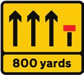
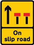
52
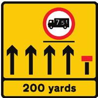
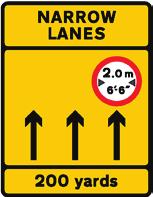
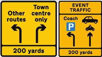
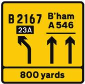
53
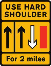
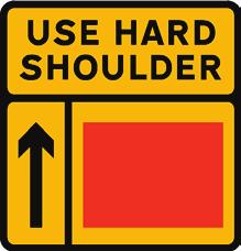
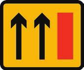
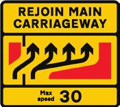

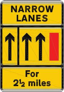
54
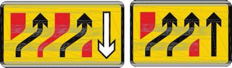
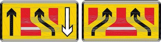
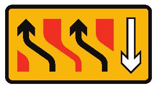

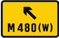
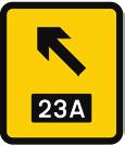


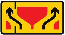
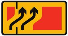


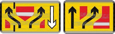


55


")


 (Previously")


56 SIGNING PRINCIPLES SIGNS PRESCRIBED WITHIN TSRGD Working Drawing No. Sign Description Sign Illustration Typical Variant Legislation/ Design Guidance P7245 (Permitted variants) (Previously P7237) Narrow lanes Typical Variant Part 1: Design, Paragraphs D and D Section U8.6 P7245 (Typical variants) (Previously P7221) Lane alignment See below for typical variants Section U8.6 Typical Variants P7245 (Typical variants) (Previously P7240) Lane loss See below for typical variants Part 1: Design, Paragraphs D and D Section U8.6 Typical Variants P7245 (Typical variants) (Previously P7250, P7256) Lane gain See below for typical variants Part 1: Design, Paragraph D and D Section U8.6 Typical Variants 53

57 SIGNING PRINCIPLES SIGNS PRESCRIBED WITHIN TSRGD U3.16 RECOVERY VEHICLE U Temporary recovery vehicle signing should follow design guidance in Part 1: Design, Section D4.10. U Recovery vehicle signing should be designed in accordance with Working Drawing P7291 and Table U The x height quoted on the Working Drawing may be reduced to a minimum of 75mm if traffic conditions and space constraint warrant such a reduction. Table 3.19 Recovery vehicle Working Drawing No. Sign Description Sign Illustration Typical Variant Legislation/ Design Guidance P7291 Information on breakdown recovery services during road works Await rescue may be varied to End TSRGD 2016 Schedule 13, Part 6 (40) Part 1: Design, Paragraphs D and D U3.17 ADVISORY SPEED LIMIT U Temporary advisory speed limit signing should follow design guidance in Part 1: Design, Section D3.7. U Advisory speed limit signing should be designed in accordance with Working Drawing P7294, with x heights ranging between 50mm minimum and 125mm maximum. The sign is always 24 stroke widths high, see Table Table 3.20 Advisory speed limit Working Drawing No. Sign Description Sign Illustration Typical Variant Legislation/ Design Guidance P7294 Temporary maximum speed in mph advised The numerals may be varied to the appropriate advised maximum speed TSRGD 2016 Schedule 13, Part 6 (41) Part 1: Design, Paragraph D
58 O1 U4 SIGNING PRINCIPLES VEHICLE MOUNTED SIGNS U4.1 INTRODUCTION U4.1.1 This section deals with vehicle mounted signs and vehicle conspicuity markings. Guidance on the use of vehicle mounted signs is provided in Part 2: Operations, Sections O8 to O11. U4.2 VEHICLE MOUNTED SIGNS U4.2.1 Vehicle mounted signing should be designed in accordance with Working Drawings P610, P7001, P7001.1, P7029, P7402, P7403 and P7404. U4.2.2 The sign to Diagram 610 can be used on roads with any speed limit and may point to the right or left as appropriate (see Table 4.1). If the speed limit is more than 30mph the sign can only be vehicle mounted when it is on the rear of a vehicle immediately ahead of another vehicle displaying the sign to Diagram Table 4.1 Keep right regulatory Working Drawing No. Sign Description Sign Illustration Typical Variant Legislation/ Design Guidance Diagram 610 P610 Sign (a) attached to the front or back of a road maintenance vehicle to indicate the side on which traffic should pass; or (b) placed in relation to an emergency or breakdown vehicle which is temporarily obstructing the road to warn other traffic of the obstruction and to indicate the way past the vehicle See description below TSRGD 2016 Schedule 13, Part 6 (11) Part 2: Operations, Sections O8.1 and O Arrow may point downwards to the left; When attached to a vehicle, the diameter of the sign may be reduced to 1200 or 900mm where it is not practicable to mount the 1500 millimetre diameter sign on the vehicle; When placed in relation to an emergency or breakdown vehicle, the diameter may be reduced to 1200 or 900mm. 55

 Part 1: Design, Paragraph D4.8.1 P7001.1 Nature of road works 1. A distance; 2. For and a distance; See description below Part 1: Design, Paragraph D4.8.2 3.")
 followed by a distance; 5. An arrow pointing to the left or to the right on its own or with the legend at 1, 3 or 4; 6.")
59 SIGNING PRINCIPLES VEHICLE MOUNTED SIGNS U4.2.3 On roads with a speed limit of 30mph or under the signs shown in Table 4.1 and 4.2 may be attached to the front or rear of a road maintenance vehicle. Table 4.2 Road maintenance vehicle Working Drawing No. Sign Description Sign Illustration Typical Variant Legislation/ Design Guidance P7001 Road works or temporary obstruction of the carriageway ahead This sign is to be used in conjunction with TSRGD 2016 Schedule 13, Part 2 (9) Part 1: Design, Paragraph D4.8.1 P Nature of road works 1. A distance; 2. For and a distance; See description below Part 1: Design, Paragraph D A word or phrase at paragraph 8 (where End indicates the end of all restrictions or prohibitions associated with road works); 4. A word or phrase at paragraph 8 (other than End ) followed by a distance; 5. An arrow pointing to the left or to the right on its own or with the legend at 1, 3 or 4; 6. On and a route number, with or without a direction of travel; or 7. A route number with or without a direction of travel; 8. The words and phrases are (a) Line painting; (b) At level crossing; (c) Blasting; (d) Ditching; (e) Grass cutting; (f) Gritting; (g) Gully emptying; (h) Hedge cutting; (i) Lighting maintenance; (j) Mobile road works; (k) On hard shoulder; (l) On slip road; (m) Overhead works; (n) Road sweeping; (o) Salting; (p) Sign erection; (q) Sign maintenance; (r) Snow ploughing; (s) Surveying; (t) Tree cutting; (u) Weed spraying; (v) End. U4.2.4 Signs mounted on convoy vehicles are to Working Drawing P7029 and Table 4.3. Table 4.3 Signs mounted on convoy vehicles Working Drawing No. Sign Description Sign Illustration Typical Variant Legislation/ Design Guidance P7029 Vehicular traffic must not overtake the vehicle used to escort other vehicles through road works The words NO OVERTAKING may be omitted and CONVOY VEHICLE may be on one line TSRGD 2016 Schedule 13, Part 6 (36) Part 1: Design, Paragraph D


 Part 2: Operations, Section O10.")


60 SIGNING PRINCIPLES VEHICLE MOUNTED SIGNS U4.2.5 The signs shown in Table 4.4 may be attached to the rear of a road maintenance vehicle. The lanes indicated as closed may be varied, as may the distances. Table 4.4 Rear mounted on maintenance vehicles Working Drawing No. Sign Description Sign Illustration Typical Variant Legislation/ Design Guidance P7402 Lanes closed to traffic ahead by vehicles carrying out mobile road works (Alternative types) Typical Variants shown below TSRGD 2016 Schedule 13, Part 6 (9) Part 2: Operations, Section O10.7 (2500 x 2500) The number of arrows and symbols indicating the number of lanes and those which are open or closed to traffic may be varied. The words 500 yds may be varied to an alternative distance to the nearest 50 yards or to Ahead or to On slip road on two lines. The distance plate may be omitted Signs may be varied to a size of 2300 x
61 SIGNING PRINCIPLES VEHICLE MOUNTED SIGNS U4.2.6 The prescribed signs to Diagrams 7403 may point to the right or left as appropriate, see Table 4.5. Table 4.5 Keep Right regulatory Working Drawing No. Sign Description Sign Illustration Typical Variant Legislation/ Design Guidance P7403 Other traffic to keep to the right of vehicles carrying out mobile road works (Alternative types) (2500 x 2500) The arrow may point downwards to the left TSRGD 2016 Schedule 13, Part 6 (10) Part 2: Operations, Section O10.7 (2300 x 3000) U4.2.7 The sign to Working Drawing P7404 may be mounted to the rear of any road maintenance vehicle, see Table 4.6. Table 4.6 Highway maintenance Working Drawing No. Sign Description Sign Illustration Typical Variant Legislation/ Design Guidance P7404 Nature of work being done by vehicle working on the highway The word HIGHWAY may be varied to MOTORWAY or ROAD. The legend may be on one line as shown below TSRGD 2016 Schedule 13, Part 6 (12) Part 2: Operations, Paragraph O5.2.8 and Section O11.8 U4.3 VEHICLE CONSPICUITY MARKINGS U4.3.1 Chevron markings should be provided on the vehicles stopping on high-speed roads in accordance with Part 2: Operations, Paragraph O U4.3.2 The rear markings for cars and vans are upward facing chevrons in red and yellow alternating stripes, as shown in Figure 4.1. Each chevron stripe should be no less than 150mm in width (larger on big vehicles) and angled upwards between 45 and 60 degrees. The red stripes must be of retro-reflective material, designed to maximise night-time visibility. The fluorescent yellow stripes are non-reflective, providing good daytime visibility and contrasting with the red. The chevrons should cover as much of the rear as possible without obscuring windows, lights or registration plates. The recommended specification for various types of vehicle are shown in Table

62 SIGNING PRINCIPLES VEHICLE MOUNTED SIGNS Figure 4.1 Rear mounted chevron markings. U4.3.3 It is also acceptable to have complete coverage of red retro-reflective material in place of chevrons on the rear but the red/yellow combination is generally considered to give the greater all round conspicuity. U4.3.4 Other reflective film products may be used instead of microprismatic material to meet minimum retro-reflective requirement for low-speed roads (under 40mph limit). Table 4.7 Recommended specification for chevron markings Vehicle type Vehicles under 7.5 tonnes (typically cars and vans) on the public highway that operate or stop for work purposes Vehicles over 7.5 tonnes (including: spreaders, gritters, tippers, Road sweepers and Recovery trucks) on the public highway that operate or stop for work purposes Incident / Mobile Support Units High speed road specification (above 40mph) (Microprismatic material) Rear chevrons in microprismatic red and non-reflective fluorescent yellow; Rear facing door edging / lockers / guardrail strips in red microprismatic; HIGHWAY MAINTENANCE (or permitted variants) in non-reflective black on either non-reflective, reflective or retro-reflective yellow; and 50mm side outline / stripe in yellow microprismatic. Rear chevrons in microprismatic red and non-reflective fluorescent yellow; Rear facing door edging / lockers / guardrail strips in red microprismatic; HIGHWAY MAINTENANCE (or permitted variants) in non-reflective black on either non-reflective, reflective or retro-reflective yellow; Directional arrow in accordance with Part 2: Operations, Paragraph O10.7.5; Rear marker chevron boards (ECE70 / 70.1); and 50mm red rear and yellow side outlines (ECE104). Rear chevrons in red and fluorescent yellow-green microprismatic; Door edging strips in red microprismatic; HIGHWAY MAINTENANCE (or permitted variants) in non-reflective black on either non-reflective, reflective or retro-reflective yellow; and Side markings at 45 degree angle. 59
63
64 O1 U5 SIGNING PRINCIPLES SIGNS PRESCRIBED BY SCHEDULE 13.9 U5.1 INTRODUCTION U5.1.1 Schedule 13, Part 9 of TSRGD provides for temporary signs to be placed on or near a road for the following purposes: convey a civil emergency warning or information; convey a temporary hazard warning; convey temporary information; or indicate the entrance to, or exit from, road works for vehicles involved in the carrying out of those works. U5.1.2 The following definitions apply: Civil emergency warning or information a warning or information about a civil emergency or the prospect of a civil emergency; Temporary hazard warning a warning about, or information on how to avoid, any temporary hazards caused by: º º º works being executed on or near a road; adverse weather conditions or other natural causes; the failure of street-lighting or malfunction of, or damage to, any other apparatus, equipment or facility used in connection with the road or anything situated on or near or under it; and damage to the road itself. Temporary information : º information about the time, date or location of road works; º º the expected delay that road works may cause; convenient routes to be followed on the occasion of a sporting event, an exhibition or any other public gathering which is likely to attract a large volume of traffic; diversions or alternative routes; check points at which drivers of goods vehicles or public service vehicles may be required to stop; the availability of new routes or destinations; and changes in route numbers. information for drivers of wide loads about action to be taken in respect of road works ahead; and requests by the police for information in connection with road traffic accidents. 61

65 SIGNING PRINCIPLES SIGNS PRESCRIBED BY SCHEDULE 13.9 U5.1.3 Further guidance on the use of Schedule 13.9 signs for temporary events is given in Traffic Advisory Leaflet 04/11. U5.1.4 Schedule 13.9 signs must not be used for enforcement purposes. U5.2 COLOUR CODING U5.2.1 The following colour combinations for static signs are permitted (see Figure 5.1): black on a background of white or yellow, using Transport Heavy font; blue on a white background, using Transport Heavy font; white on a blue background, using Transport Medium font; and white on a red background, using Transport Medium font. Figure 5.1 Schedule colour combinations U5.2.2 The background must be red and any letters, numerals, other characters, chevrons or borders must be white if the sign: conveys a temporary hazard warning; conveys only temporary information for pedestrians, cyclists or pedestrians; or indicates the entrance to, or exit from, road works for vehicles involved in the carrying out of those works. Text on red background signs is always in upper case lettering, unless otherwise shown on a Working Drawing. U5.2.3 The background must be yellow and any letters, numerals, other characters, chevrons or borders must be black if the sign conveys: temporary information (other than for pedestrians, cyclists or equestrians) in connection with road works; or information about check points at which goods vehicles or public service vehicles may be required to stop. U5.2.4 A variable message sign may have a black background and, if it does, any letters, numerals, other characters or chevrons must be white or yellow. Alternatively a variable message sign may have a yellow background and if it does, any letters, numerals, other characters or chevrons must be black. See Section U
66 SIGNING PRINCIPLES SIGNS PRESCRIBED BY SCHEDULE 13.9 U5.2.5 If a sign contains warnings about, or information on how to avoid, any temporary hazards caused by any of the items listed below, the sign must be white on a red background. Note: Text on red background signs is always in upper case lettering, unless otherwise shown on a Working Drawing. Variable message signs may be white, off-white or yellow on a black background or black on a yellow background, except when the sign is not in use when it should display a plain black or grey face unless otherwise authorised. See Section U5.16. U5.3 SIGN DESIGN U5.3.1 Static signs should have no more than 12 units of information with a unit defined as a word, name, date or symbol. For example, the signs shown in Figure 5.1 each have 3 units of information. Designers should look critically at their designs and eliminate any superfluous items to help ensure driver comprehension. U5.3.2 An assumption can be made that a driver would read either the English or Welsh element of a bilingual sign, so the number of units could be increased further. For bilingual signs, therefore, the maximum number of units can be increased to 14 (i.e. 7 English and 7 Welsh). U5.3.3 Distances must be given as yards, yds, mile or miles. Where distances are less than ½ mile, they must be expressed in yards, to the nearest 10 yards, however the distances of ¼ or 1 /3 mile may be used. Where distances greater than ½ mile are indicated they may be one of the following: 3 m, 2¾ m, 2 2 /3 m, 2½ m, 2 1 /3 m, 2¼ m, 2 m, 1¾ m, 1 2 /3 m, 1½ m, 1 1 /3 m, 1¼ m, 1 m, ¾ m or 2 /3 m. Distances greater than 3 miles must be quoted to the nearest whole mile. U5.3.4 Time periods, in any combination, should be expressed as: Monday or any other day of the week, abbreviated as appropriate; Monday Saturday or any other days of the week, abbreviated as appropriate e.g. Tue, Wed, Thur etc.; am, 8.30 am 3 pm, 2 3 pm, Midnight 6 am, Noon 9 pm or any other time periods as appropriate. N.B. the 24 hour clock must not be used to define times; or 1 May 30 September or any other dates, abbreviated as appropriate, which may include references to bank and public holidays. U5.3.5 The inclusion of web addresses is not permitted on temporary signs. Except for Police requests for information, it is not acceptable to include telephone numbers on signs prescribed by Schedule 13 Part 9 if the x height of the text is less than 100mm, or less than 150mm where the 85th percentile approach speed is over 40mph. It is therefore recommended that if the nature of a warning or information included on a temporary sign is likely to justify the display of a telephone number to contact then a Diagram sign (Schedule 13 Part 6 Item1) should be placed downstream of the relevant sign to Schedule 13 Part 9. The distance between the signs should be the relevant clear visibility distance for the expected traffic speed. 63
67 SIGNING PRINCIPLES SIGNS PRESCRIBED BY SCHEDULE 13.9 U5.4 x HEIGHT U5.4.1 The x height of Schedule 13.9 signs, unless otherwise indicated on Working Drawings, should be of one size for an individual sign. Varying sizes of text can place undesirable emphasis on part of a legend. U5.4.2 On bilingual traffic signs the x height should not be reduced to fit both languages on a standard size temporary sign face, rather, a larger sign face should be used to accommodate both languages at the appropriate x height for the conditions, unless otherwise shown on Working Drawings. U5.4.3 Standard rules for the capitalisation of proper nouns should be used on traffic signs, i.e. a proper noun should always begin with a capital letter. Examples of proper nouns are: geographic place names e.g. Epsom Town Centre or South East England ; company or organisation names e.g. Highways England ; and holidays e.g. Easter. U5.4.4 Other terms such as town centre, the contractor or summer are not proper nouns and should not begin with a capital letter. U5.4.5 Unless otherwise shown on Working Drawings, x height sizes for Schedule 13.9 signs are shown in Table 5.1. Table 5.1 x height sizes for Schedule 13.9 signs 85th percentile approach speeds of private cars/ speed limit Examples of typical roads for which Column 1 may apply Minimum x height (millimetres) Up to 20mph Very narrow and urban roads to 30mph Urban and rural roads of local character to 40mph 40 to 50mph 50 to 60mph 60 to 70mph 70mph Urban and rural single 2-lane roads (7.3m wide with 1m hard strips) High standard rural single roads (7.3m wide with 1m hard strips) Urban all-purpose dual carriageway roads Wide single carriageway roads (10m wide) Urban all-purpose dual carriageway roads High standard all-purpose dual carriageway roads Motorways with a speed limit less than 70mph All-purpose grade separated dual carriageway roads and motorways Where a sign includes a telephone number, the x height must not be less than 100mm. 64
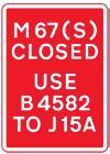
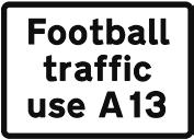
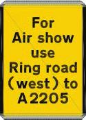

68

69 SIGNING PRINCIPLES SIGNS PRESCRIBED BY SCHEDULE 13.9 U5.6 INFECTED AREAS U5.6.1 Where signing is required to warn the public that they are entering an area infected with an animal disease, signing complying with Working Drawing P574 should be used. The name of the disease may be omitted or varied as required. See Table 5.3. Table 5.3 Warning of infected areas Working Drawing No. Sign Description Sign Illustration Legislation/Design Guidance P574 Area infected by animal disease ahead In agreement with local public health officers The word RABIES may be omitted or varied to any appropriate animal disease name on one or two lines. AHEAD may be omitted or varied to ENDS or a horizontal arrow pointing left or right U5.7 INCIDENT MANAGEMENT U5.7.1 Non-police incident management signs are shown in Table 5.4, with further design details shown in Section U8.3. The non-police USE HARD SHOULDER sign may only be deployed with the permission of a police officer in uniform or a traffic officer. U5.7.2 Service Providers may be required or directed to provide Emergency Traffic Management (ETM) by the police, traffic officer or other emergency Service Provider whether or not there are formal incident support units provided for in contracts or agreements (see Part 2 Operations: Section O7). U5.7.3 When requested to provide enhancements to Emergency Traffic Management (enhanced ETM), where incidents are expected to last for more than 20 minutes, Service Providers should provide sufficient TTM equipment and vehicles in the initial response to either close the carriageway or implement a taper leaving one lane open at the location of the incident. Service Providers should therefore identify which section of their networks would require additional resources to be available e.g. four or five lane sections. When Service Providers are contacted to provide enhanced ETM they should confirm the location of the incident if the information provided is not sufficient to identify the initial TTM requirements. U5.7.4 The storage location and quantity of any TTM equipment and works vehicles (including IPVs) would need to be identified by the Service Provider s risk assessment or in the relevant contract or agreements. U5.7.5 For medium term duration incidents (between 20 and 90 minutes) the provision of additional TTM equipment and/or IPVs over and above that identified in this section may be limited by the location and number of incidents. For long duration incidents (over 90 minutes) it is considered reasonably practicable for a Service Provider to install enhanced ETM complying to the normal requirements of planned works in Part 1. U5.7.6 Signs in Table 5.4 are often of a roll-up type. These signs should always be fabricated using retroreflective sheeting. 66


70 SIGNING PRINCIPLES SIGNS PRESCRIBED BY SCHEDULE 13.9 Table 5.4 Non-police incident management Working Drawing No. Sign Description Sign Illustration Legislation/Design Guidance Potential danger temporarily ahead and consequent need to proceed with caution Part 2: Operations, Paragraph O7.1.6 Traffic should use the hard shoulder in an emergency Part 2: Operations, Paragraph O7.1.6 End of temporary permission for traffic to use the hard shoulder Part 2: Operations, Paragraph O7.1.6 U5.7.7 Schedule 13.9 signs erected by or for the police, requesting information about road traffic accidents, should have as brief a message as possible so as not to distract drivers unduly. The telephone number used should be no longer than three digits. Although the sign can be to any of the colour combinations listed in Schedule 13.9, it is recommended that white on blue be used. An example sign face is shown in Table 5.5. Table 5.5 Typical police request for information sign Working Drawing No. Sign Description Sign Illustration Legislation/Design Guidance Police request for information In agreement with local police procedures 67

71 SIGNING PRINCIPLES SIGNS PRESCRIBED BY SCHEDULE 13.9 U5.8 VEHICLE CHECK POINT U5.8.1 Guidance on the use of vehicle check point signing provided in Part 1: Design Paragraph D should be followed. The deployment of vehicle check point signing should follow the principles shown in TA11. U5.8.2 For further details of permanently sited vehicle check point signs, refer to Working Drawings P832.8, P832.9 and P832.10A, Section U3.6 and see Table 5.6. Table 5.6 Vehicle check point Working Drawing No. P832.8 Sign Description Sign Illustration Typical Variant Goods vehicles should leave the main carriageway of a road on the approach to a goods vehicle check point The legend may be varied to All goods vehicles and PSVs or All PSVs The direction in which the arrow points may be varied Legislation/ Design Guidance Part 1: Design, Paragraph D P832.9 Direction to a vehicle check point The direction in which the sign points may be reversed Part 1: Design, Paragraph D P832.10A End of vehicle check point area N/A Part 1: Design, Paragraph D U5.9 DIVERSION SIGNING U5.9.1 Guidance on the use of diversions and road closures is provided in Part 1: Design, Section D3.15 and Section U7.2 of this guidance. U5.9.2 Diversion route signing should generally follow standard sign design rules, as laid out in TSM Chapter 7 and be at a suitable x height for the 85th percentile approach speed of traffic given in Appendix A1. U5.9.3 The legend DIVERSION should normally be used at the start of the diversion route rather than being encountered along the diversion route. The exception to this is where a sign to Working Drawing P2716 is used. U5.9.4 Diversion route signs may incorporate a symbol (from Working Drawing S56) indicating to drivers the route to follow. Routes signed with a symbol should always have a worded sign at the start of the route indicating to drivers the symbol they are to follow. See Working Drawings P2703, P2704, P2706 and P2716; and in Table

72


73 SIGNING PRINCIPLES SIGNS PRESCRIBED BY SCHEDULE 13.9 Working Drawing No. P2706 Sign Description Sign Illustration Typical Variant Map type advance direction sign indicating temporary diversion Map type signs should have arms 4 stroke widths wide. See TSM Chapter 7 for further details of map type sign design, including the addition of warning triangles and regulatory roundels Legislation/ Design Guidance Part 1: Design, Section D3.15 and Paragraph D4.2.8 P2716 Junction ahead leading to a temporary diversion route, the direction along which is indicated by a symbol shown on Working Drawing S56 See description below Part 1: Design, Section D3.15 and Paragraph D M1 North may be varied to the name of a road, to a route number and a place name or to a description of a route. Closed may be varied to closed to and a type of vehicle or road user. The upper part of the sign may be omitted. Alternative route may be varied to To re-join with or without a route number. To and a destination may be added after Alternative route. The diversion symbol may be varied to any of those shown on Working Drawing S56, to any combination of place names and route numbers, to a description of a route or to the name of a road. The term follow may be varied to use or via as appropriate. Hollow or solid combinations of the same shape diversion on the same or overlapping route should be avoided as the symbols cannot be clearly represented on matrix signals. The legend Alternative route is only used when an alternative route is signed. The use of Find alternative route or similar is not acceptable. An alternative to the sign shown on Working Drawing P2716 is shown below. A simple two panel sign following standard design rules may be used. Such a sign may be used at closed exit slip roads on motorways or dual carriageways for example. Typical Variants U5.9.5 Signs on the approach to and at the start or end of a diversion route on a low speed road may be on standard 1050 x 750mm plates, see Working Drawing P2702 and see Table


74 SIGNING PRINCIPLES SIGNS PRESCRIBED BY SCHEDULE 13.9 Table 5.8 Low speed road diversion signing Working Drawing No. P2702 Sign Description Sign Illustration Typical Variants Start of temporary diversion route The arrow direction may be varied. The arrow symbol may be replaced by the word ENDS or a distance in yards up to 400 yards (to the nearest 10 yards) Legislation/ Design Guidance Part 1: Design, Section D3.15 U5.10 ADVANCE SIGNING U Guidance on the use of advance signing of road works is provided in Part 1: Design, Sections D4.12 and D4.13. U This signing should be designed in accordance with Working Drawings P7001.3, P7002A, P7002B and P and Table 5.9. U Designers should carefully consider whether or not signs giving notice of road closures taking place at some point in the future should include specific times on them. The inclusion of times may give drivers a false impression of the availability of routes, where unforseen circumstances mean the actual closure times vary from those quoted on a sign. Where it is felt necessary, timing references should be limited to such phrases as overnight, off-peak hours, daytime, next weekend and the like. See also Paragraph U Table 5.9 Advance notification Working Drawing No. P Sign Description Sign Illustration Typical Variant Vehicular traffic should proceed slowly owing to workforce in road ahead WORKFORCE IN ROAD may be varied to SETTING OUT ROAD WORKS AHEAD and SLOW may be omitted Legislation/ Design Guidance Part 1: Design, Paragraph D P7002A Major road works at a specified location ahead Part 1: Design, Paragraph D Details of road works may be varied` as appropriate. J6 and J13 may be varied to Junctions 6 and 13. The bottom panel may be omitted. 71


75 SIGNING PRINCIPLES SIGNS PRESCRIBED BY SCHEDULE 13.9 Working Drawing No. P7002B Sign Description Sign Illustration Typical Variant Time and date when a route is to be closed to traffic Legislation/ Design Guidance Details of route to be closed and dates may be varied as appropriate. Junction 16 to 15 may be varied to J16 to J15 Part 1: Design, Paragraph D P Dates when road works are to take place overnight and delays are to be expected Details of road works may be varied as appropriate. Expect delays may be varied to Delays possible. The description may be on five lines rather than three Part 1: Design, Paragraph D U5.11 HAZARD INFORMATION OR WARNING U Guidance on the use of hazard information and warning signs is provided in Part 1: Design, Sections D3 to D6. U This signing should be designed in accordance with Working Drawings P7010.1, P7013, P7015, P7016, P7017, P7018.1, NP430 and NP431; and Table Table 5.10 Hazard signing Working Drawing No. Sign Description Sign Illustration Typical Variant Legislation/ Design Guidance P Vehicular traffic should proceed slowly owing to temporary hazard resulting from wet tar on the road See description below Part 1: Design, Sections D3.15, D3.18 and Paragraph D SLOW WET TAR may be varied to the following: ADVERSE CAMBER, RAMP AHEAD, ROAD AHEAD CLOSED, ROAD CLOSED (name of road may be substituted for ROAD ), TEMPORARY ROAD SURFACE, TRAFFIC CONTROL AHEAD, TRAFFIC SIGN MAINTENANCE, TRAFFIC SIGNAL MAINTENANCE or WORK IN CENTRE OF ROAD. 72


 N/A Part 1: Design, Paragraph D3.32.9 and D4.6.")
 LEFT may be varied to RIGHT or BOTH WAYS Part 1: Design, Paragraphs D3.32.7 and D6.4.9 P7018.")
76 SIGNING PRINCIPLES SIGNS PRESCRIBED BY SCHEDULE 13.9 Working Drawing No. Sign Description Sign Illustration Typical Variant Legislation/ Design Guidance P7013 Temporary sudden change in level of carriageway surface N/A Part 1: Design, Section D3.18 and Paragraph D P7015 Temporary absence of hard shoulder for specified distance The legend may be on three lines. The distance may vary Part 1: Design, Paragraphs D and D P7016 Zebra or signal controlled crossing facility temporarily out of use. (Sign for pedestrians, cyclists or equestrians) N/A Part 1: Design, Paragraph D and D4.6.2 P7017 Direction in which pedestrians should look for approaching traffic. (Sign for pedestrians) LEFT may be varied to RIGHT or BOTH WAYS Part 1: Design, Paragraphs D and D6.4.9 P Pedal cyclists to dismount and use adjacent footway N/A N/A NP430 Warning for traffic of the possible requirement to stop on the approach to a section of carriageway subject to a Mobile Carriageway Closure N/A Part 2: Operations, Plan MCC3 NP431 Point at which traffic shall wait for a Mobile Carriageway Closure convoy to pass N/A Part 2: Operations, Plan MCC3 73
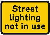
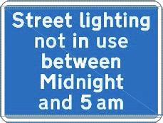
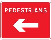
77


78 SIGNING PRINCIPLES SIGNS PRESCRIBED BY SCHEDULE 13.9 U5.14 WIDE LOAD U Guidance on the use of wide load signing is provided in Part 1: Design, Section D4.10. U Wide load signing should be designed in accordance with Working Drawings P7292 and P7293; and Table U The x heights quoted on the Working Drawings may be reduced to a minimum of 75mm if traffic conditions and space constraint warrant such a reduction. Table 5.13 Wide load signing Working Drawing No. Sign Description Sign Illustration Typical Variants Legislation/ Design Guidance P7292 Instructions to drivers of wide loads on action to be taken before reaching road works ahead Typical Variants See description below Part 1: Design, Paragraphs D and D Dimensions may be varied or omitted as appropriate. Follow diversion at next exit may be varied to an appropriate instruction, see description below. The sign description may be on four, five or six lines. Example of instructions: Contact police from emergency phone, Straddle nearside two lanes, Use offside lanes at next overbridge, Stop at next lay-by, Phone Bridge Authority ahead, Stop at holding area 2 miles ahead or For docks use A123(E). P7293 Instructions to drivers of wide loads on location from which they should telephone for assistance N/A Part 1: Design, Paragraphs D and D U The instructions to the driver may vary from those shown on the Working Drawings to suit the situation. Any such instructions should be checked to ensure that they are as brief as possible. Telephone numbers should not be included on signs in locations where it is not possible for a vehicle to stop. U A supplementary plate giving a telephone number, may be added below the 7293 sign as required. Such a plate must not be installed at a location in which a vehicle may not stop. The plate should be to the same x height as the 7293 sign. An example plate is shown in Figure 5.3. Figure 5.3 Telephone number supplementary plate 75


79 SIGNING PRINCIPLES SIGNS PRESCRIBED BY SCHEDULE 13.9 U5.15 WORKS TRAFFIC U Guidance on the use of works traffic signing is provided in Part 1: Design, Sections D3.21 and D3.22. U Signing relating to works accesses, exits and the routing of works traffic should be designed in accordance with Working Drawings P7301 to P7307 inclusive, and Table Table 5.14 Works Traffic Signs Working Drawing No. Sign Description Sign Illustration Typical Variants Legislation/ Design Guidance P7301 Temporary access to a construction or road works site The term WORKS ACCESS may be varied to WORKS TRAFFIC ONLY or NO WORKS TRAFFIC The description may be on two or three lines Part 1: Design, Paragraph D P7302 Temporary exit from a construction or road works site N/A Part 1: Design, Paragraph D The direction of the arrow may be varied P7303 Direction to be taken by road works or construction traffic at a junction ahead Part 1: Design, Paragraph D P7304 Direction to be taken by road works or construction traffic at a junction or works entrance ahead The direction of the arrow may be varied Part 1: Design, Paragraph D
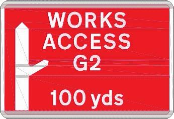
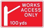
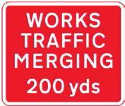
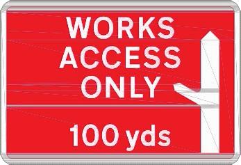
80
81 SIGNING PRINCIPLES SIGNS PRESCRIBED BY SCHEDULE 13.9 U All parts of the sign other than those facing traffic should be coloured grey or black or be in a nonreflective metallic finish. Any lettering required for identification purposes should be no more than 25mm high on the sign housing or, if applied by means of a label, should be printed on a label that is either transparent or the same colour as the sign housing. On no account should any label or any part of the sign housing comprise retroreflective material. VMS must conform to the requirements of BS EN U Any part of the sign surrounding the rectangular area used to display a message should be coloured grey or black. There must be no text or symbols on the surround as this would render the sign unlawful. U Text on a light-emitting VMS must be displayed in white, off-white or yellow. A prescribed sign incorporating a black legend or symbol on a white or yellow background may be displayed with the colours reversed, i.e. as a white, off-white or yellow symbol on a black background. Any red triangle or circle forming part of the sign must be displayed in red. A VMS should exhibit a black or grey rectangular area when no message is being displayed. U Table 5.15 sets out the minimum sizes of text recommended for use on light-emitting VMS. A VMS that displays a sign shown in one of the Schedules to TSRGD must do so at the prescribed size appropriate to the traffic approach speed, unless special authorisation has been obtained. In practice, the more complex pictograms contained within many warning signs lose resolution at smaller sizes and so the largest size (generally 1500mm) should be used wherever possible to ensure adequate clarity. 78
82 Table 5.15 Sizes of characters on Verge Mounted VMS. x-height of transport alphabets (millimetres) Upper case letter height (millimetres) 85th percentile approach speed of private cars (mph) Number of words in longest message to be displayed Motorways and all-purpose dual carriageway roads with hard shoulders 2 lane 3 lane 4 lane Verge mounted signs All-purpose roads without hard shoulders D = dual carriageway roads S = single carriageway roads 1 lane D 2 lane S 2 lane D 4 lane S Motorways and all-purpose dual carriageway roads with hard shoulders 3 lane D 2 lane 3 lane 4 lane Verge mounted signs All-purpose roads without hard shoulders D = dual carriageway roads S = single carriageway roads 1 lane D 2 lane S 2 lane D 4 lane S 3 lane D Column 1 Column 2 Column 3 Column 4 Column 5 Column 6 Column 7 Column 8 Column 9 Column 10 Column 11 Column 12 Column 13 Column 14 Up to and Including Over 30 and up to and including Over 40 and up to and including 50 Over 50 and up to and including 60 Over SIGNING PRINCIPLES SIGNS PRESCRIBED BY SCHEDULE 13.9
83 SIGNING PRINCIPLES SIGNS PRESCRIBED BY SCHEDULE 13.9 U On roads where the 85th percentile approach speed of private cars, as determined in accordance with TA 22, is greater than 40mph, it is recommended that two VMS displaying the same legend are provided where possible. This is especially important if the information to be displayed is likely to conflict with that on fixed directional signs, for example a VMS message indicating a mandatory or advisory diversion. U Messages should be as short as possible while being fully comprehensible to drivers. They should not normally consist of more than eight words or six units of information, see Table Table 5.16 Number of words comprising Unit of Information for VMS legends Type of Legend Place name or other destination, even if it consists of more than one word, e.g. STOKE-ON-TRENT or FORTH ROAD BRIDGE Place name with associated compass point, e.g. READING (E) or SLOUGH (WEST) Place name with associated route number, e.g. DORKING A24 or LAMPTON (M11) Location comprising route number, junction number or numbers and compass point, e.g. M6 J20-21 NORTH Unit of Information Number of Words 1 1, 2 or or Distance, e.g. 600 YDS or 3 MILES 1 1 All other words, with the exception of prepositions, regardless of length, e.g. FOG or WORKFORCE 1 1 Driver information consisting of up to three words (as a defined above), e.g. ACCIDENT, LONG DELAYS or REJOIN MAIN CARRIAGEWAY Prescribed sign, e.g. warning triangle, speed limit roundel or wicket (lane closure) pictogram Supplementary information associated with warning signs, e.g. 3 MILES or ICE 1 1, 2 or Arrow or emergency diversion route symbol 1 0 Punctuation marks, dashes, etc. 0 0 U All messages must be displayed on a single sign aspect. It is unlawful to display messages that require the use of multiple displays (e.g. paging or scrolling text). Where possible, the prescribed messages in TSRGD should be used. A temporary VMS may be used to display messages for the same purposes as a temporary fixed sign. Schedule 13.9 permits the placing of temporary signs to convey to traffic various types of message, see Section U5.3. All other messages require authorisation by the authorising body. This is also the case where TSRGD messages are to be displayed in mixed (sentence) case text or where pictograms to be incorporated into messages are either not prescribed in TSRGD or are prescribed for a different purpose. 80
84 SIGNING PRINCIPLES SIGNS PRESCRIBED BY SCHEDULE 13.9 U To assist driver assimilation of VMS, non-prescribed legends should broadly follow the same principles as the prescribed legends in TSRGD. Strategic traffic and diversion legends should be constructed such that the information appears in the following order: location e.g. M1 J3-4 NORTH; problem e.g. ACCIDENT; effect e.g. LONG DELAYS; and guidance e.g. USE M40. U Depending on the capability of the VMS, some information might have to be omitted. In general, the effect is more important than the problem. Guidance should only be given when it will be supported by other signing in the area. U VMS can be used to forewarn drivers of future events that might affect journeys. These could include road works or major events. Advance or remote notice of road works should follow the order and style of the information on signs to Working Drawings 7002A to Advance notice of major events should follow the same broad principles. Dates and times must be expressed in the formats prescribed in TSRGD, see Paragraph U The 24 hour clock must not be used under any circumstances. U TSRGD permits the display of flashing amber lamps with certain types of display. Generally for temporary VMS considered in Chapter 8 this means they may only be displayed with immediate safety-related and tactical diversion messages. They may not be displayed with other types of message such as advanced notice of special events or strategic diversion messages. When a non-prescribed legend is specially authorised, flashing amber lamps may only be used with that message if the authorisation expressly permits it. U The siting of VMS should be carefully considered to ensure safe access for maintenance personnel. Such signs may be trailer or post mounted behind a vehicle restraint system as necessary. Where a temporary VMS is to be in place for a considerable period of time, consideration should be made to mounting the sign on posts and providing a mains power supply. The posts should be passively safe if site conditions warrant this. See also Part 1: Design, Section D3.38 for further details on the use of temporary VMS. 81
85
86 O1 U6 SIGNING PRINCIPLES EXCEPTIONAL NON-PRESCRIBED SIGNS U6.1 INTRODUCTION U6.1.1 The changes to the TSRGD have increased the range of signs for temporary situations which have either been specifically prescribed or covered under Schedule It is expected that there will be very few occasions which necessitate the use of signs which are not permitted by the TSRGD. For these limited situations, signs of different natures can be authorised by the relevant authorising body. Due to the frequent changes in technology and available products, many vehicle mounted signs are also permitted for use by authorisations. U6.1.2 There are legal limitations on what, and how, signs can be authorised. In addition, for temporary signs relating to road works and any other construction activities, those authorising signs may take on some designer responsibility for the adequacy of the sign design; therefore there may be some additional limitations on what can be authorised where there is insufficient evidence relating to the safety of a proposed sign. A summary of the limitations include: it is not possible to authorise a prescribed sign to have the same legal meaning as another prescribed sign; there are limitations on the design of signs which indicate mandatory requirements or prohibitions to road users; authorisations indicate if signs have to be installed at a specific location, can be used over a length of a route within a single authority or over the network of a single authority (e.g. vehicle mounted signs). A single authorisation cannot permit a sign to be used in more than a single authority, although it is possible for a sign to be covered by more than one authorisation. This permits portable and mobile signs and equipment to be used in multiple authorities; it is not possible to include certain elements, e.g. web addresses, where there is insufficient data to show that the sign would be safe; authorisations may limit the use of signs and equipment covered by them; this can include how they could be used; with what other signs they may, must, or must not be used: any type approval requirements; and what training requirements are needed for use. If using authorised signs it is recommended that designers and supervisors check for specific requirements; sign authorisations are solely at the discretion of the authorising body and may be revoked; and signs may be required to be trialled or tested on or off-road before temporary or permanent authorisations can be agreed. The nature of these trials or tests will need to meet the requirements of the authorising body and may vary from sign to sign. U6.1.3 If a maintaining organisation identifies the need for a sign authorisation, they should contact the relevant authority who will identify the relevant organisation with whom delegated rights for authorisation rests. The procedure for seeking sign authorisation should be checked, particularly with respect to the information required and timescales for processing applications. U6.1.4 Where generic products require authorisation manufacturers may contact the relevant authorising body for any specific requirements; however, products will be authorised on an authority basis and it is recommended that applications for authorisation be forwarded by the relevant authority. Manufacturers may also be able to obtain help and guidance from the relevant trade bodies. 83
87 SIGNING PRINCIPLES EXCEPTIONAL NON-PRESCRIBED SIGNS U6.2 VEHICLE MOUNTED SIGNS U6.2.1 Signs can only be attached to vehicles if specifically permitted in the Regulations (see Section U4.2) or if stated in an authorisation. Prescribed signs can be used on vehicles in motion or stationary. Authorisations may sometimes permit signs, or specific aspects, to be placed on vehicles only when stationary; any limitations should be identified before use. Where vehicles, or trailers, are used as support for other signs, as a minimum, the ignition should be off; the TTM Provider should check with the authority for specific requirements. U6.2.2 There are various types of light arrow authorised. These can consist of individual lamps to make up the arrow or they can be displayed on LED matrix panels. The later versions have the benefit of being able to display other signs (e.g. Diagram 7402 wicket signs see Table 4.4) and legends. A full light arrow, with associated impact protection device, requires a large vehicle. For some locations, and some activities, works vehicles are not able to mount a full size light arrow; in several authorities mini-light arrows have been authorised for use as a replacement for Diagram 610 and/or Diagram 7403; the limitations for use are not standard for all products and for all authorities and the authorisation should be checked for specific requirements. U6.2.3 While the use of light arrows formed using individual lamps is an acceptable option it is recommended that authorities and those undertaking works consider using vehicles using LED matrix panels for some types of works. These are more flexible and allow vehicles to be used for other activities e.g. for mobile works wicket signs or mobile carriageway closures. While some existing products have been authorised using amber and offwhite aspects, it is expected that future products will only be authorised which display wicket signs, legends etc. using white LEDs. Also it is expected that those parts of signs prescribed as being red e.g. T bars, warning triangles, are displayed as that colour. In many cases signs are authorised at sizes that can be used at all traffic speeds; however, some signs, or individual aspects are only authorised for use up to a set speed limit. U6.2.4 There are other limitations on use e.g. a maximum height of 5.03m for a mobile sign (except when used only on a high route). It is therefore vital that those driving, operating or supervising the works are aware of both general requirements (e.g. Highway Sector Scheme 12C) and any vehicle specific requirements for use when both stationary and in motion. This is particularly important for general hire vehicles or vehicles used in more than one authority. U6.2.5 In addition to the signs (including the individual aspects) being authorised for use for the works being undertaken, those using the vehicles should identify that the mechanisms (whether mechanical or electrical) for bringing the sign, or aspects, into use does not impact on the safety or effectiveness of the sign in use. It is therefore considered reasonably practicable to only use equipment certified by a relevant national and competent body (e.g. TOPAS). U6.2.6 Owners of IPVs should consider fitting High Definition camera systems, either rear facing or 360º both to give operatives clear information of the area around the vehicle and also to record any near misses or IPV strikes. In addition, consideration of fitting reliable detection systems for vehicles approaching close to the rear of IPVs should be made. It is likely that in the future, authorisations are likely to be revoked or amended to set dates when these types of systems must be used. 84
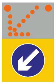

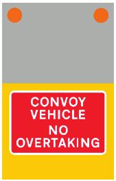
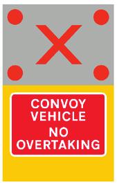
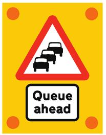
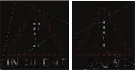

88
89
 signals; amendments to approach and lane-change zone signing for relaxation closures; alternative entry taper application and use, works site")
90 O1 U7 OPERATIONAL ISSUES U7.1 INTRODUCTION U7.1.1 Operational issues covered in this section are diversion signing principles associated with slip road closure; the use of Impact Protection Vehicles for Temporary Traffic Management; Lane Control (Red X ) signals; amendments to approach and lane-change zone signing for relaxation closures; alternative entry taper application and use, works site signs and signals and scheme inspections. U7.2 DIVERSION SIGNING SLIP ROAD CLOSURES U7.2.1 Typically these closures occur overnight or during off-peak periods to facilitate work which might otherwise be difficult to carry out safely, due to a combination of traffic speeds and limited working areas. U7.2.2 When a slip road at a grade separated junction is closed, it is often convenient to simply direct traffic to the next grade separated junction up or down stream. This helps to ensure that traffic is not diverted onto other roads which may not be suitable for the traffic which otherwise would have accessed the closed slip road. Local knowledge of the surrounding network and traffic conditions should be used to determine the most appropriate diversion route. U7.2.3 A two-panel sign to working Drawing P2716 (see Table 5.8) may be used at the start of the closure. Such a sign may be particularly useful if symbolic diversion signs are being used. Alternatively, a ROAD CLOSED sign to Working Drawing P may be used. See Figures 7.1 and 7.2 for typical signs for closed entry and exit slip roads. Figure 7.1 Diversion route signing for a closed entry slip 101

91 OPERATIONAL ISSUES Figure 7.2 Diversion route signing for a closed exit slip U7.2.4 If symbolic signing is used, care should be taken to ensure that the chosen symbol does not conflict with the same symbols on other signs which carry diversion symbols along the diversion route. Such a match could cause diverted traffic to become misdirected. Similarly if worded signs are used, a check should be undertaken to ensure that other worded diversion signs are not present from other works in the area. U7.2.5 Additional signing will be needed if there are intermediate junctions present between the closed slip road and the junction at which traffic U-turns. Typically these intermediate signs will take the form of a sign to Working Drawing P2703 with either a worded legend or a diversion symbol and an arrow pointing in the appropriate direction. If the intermediate junction is an at-grade junction, the P2703 will usually suffice providing that the route through the junction is otherwise obvious. If the diversion route at an intermediate junction requires traffic to turn off a through-route, additional signs to P2703 or P2704, as appropriate, may be required. On the approach to a roundabout, as long as signs to P2704 are installed to guide traffic around to the relevant exit, there should be no need to provide a map type sign to P2706, as a sign to P2703 will provide adequate guidance. U7.2.6 Although signs to Working Drawing P2702 are generally not suitable for use on high speed dual carriageway roads due to their small size, a P2702 bearing the legend Diversion ENDS may be installed on a slip road to indicate to traffic that either they have returned to the junction they were wishing to use or are about to re-join the route they were diverted from. U7.2.7 Drivers with local knowledge may find it preferable to leave a route at a junction prior to a closed exit slip road should a suitable alternative route be available. This is particularly the case if the signed diversion route from the closed slip road is significantly longer than that via a potential alternative route. A sign advising of the closed exit slip road should be installed prior to the junction where drivers may leave to use the alternative route. The sign should be located at a sufficient distance from the junction for drivers to make a decision as to whether or not to make a voluntary diversion, see Figure 7.3. It is not generally recommended that this voluntary alternative route be otherwise signed, other factors may make the route undesirable to be used by drivers not familiar with the area. Prior to using this type of sign, the relevant authority for the alternative route should be consulted. 88

92 OPERATIONAL ISSUES Figure 7.3 Advanced signing for a closed exit slip road U7.3 THE USE OF IMPACT PROTECTION VEHICLES FOR TEMPORARY TRAFFIC MANAGEMENT U7.3.1 The purpose of IPVs is to: alert road users to the presence of road works vehicles on the hard shoulder or on the carriageway and, by association, road workers; provide appropriate information and instruction to road users through the use of prescribed or otherwise authorised traffic signs; reduce the severity of injury to road users should a collision with a works vehicle occur; reduce risks to road workers on foot on the carriageway and working on the rear of works vehicles; and reduce risks to road workers in and around temporary traffic management vehicles and other works vehicles. U7.3.2 The Management of Health and Safety at Work Regulations require Service Providers to undertake a suitable and sufficient assessment of the risks to the health and safety of their employees. See also Part 2: Operations, Paragraph O U7.3.3 This section builds on the above requirement, by providing guidance on the basis for the risk assessment. U7.3.4 The risk assessment should be site specific, suitably recorded and consider all relevant factors that may affect the risks associated with an operation. The risk assessment should also record the method used to install, maintain or remove temporary traffic management, specifically including the use of dual or single vehicle working. 101
93 OPERATIONAL ISSUES U7.3.5 The installation, maintenance and removal of temporary traffic management may be carried out using one of the following options: dual vehicle working. This is two vehicles working together with an IPV positioned 75m (+/-25m) upstream of the works vehicle; or single vehicle working. This is one vehicle which acts as both IPV and works vehicle. U7.3.6 The use of dual or single vehicle working is likely to result in different injury risks for road workers. This difference in injury risk means that the choice of dual or single vehicle working (and the separation distance if dual vehicle working is used) can be crucial to ensuring that the risk to both road workers and road users is managed to a level that is As Low As Reasonably Practicable. Refer to Part 2: Operations, Section O2.3. U7.3.7 In some circumstances, it may be appropriate to use more than two vehicles with more than one upstream IPV. The principles of dual vehicle working apply equally to such scenarios. U7.3.8 Dual vehicle working refers to the use of two vehicles that work together at a separation distance of 75m (+/-25m). The first (upstream) vehicle is fitted with a Lorry Mounted Crash Cushion (LMCC) and offers protection to the downstream works vehicle. Where practicable, the works vehicle may also be fitted with an LMCC. U7.3.9 Signing on the vehicles should comply with the recommendation in Part 2: Operations, Paragraphs O5.5.5 and O for the working vehicle. Vehicle mounted approach signs identified in Plans MLC1 to MLC5 may be replaced where suitable signals or remote control fixed taper point signs are available. U Research indicates that, when working in a live lane, dual vehicle working may achieve the lowest level of relative risk to road workers. U When working on a motorway or dual carriageway, dual vehicle working should normally be used when installing, maintaining and removing temporary traffic management, in accordance with the HTMA guidance document. Following the HTMA guidance document, temporary traffic management vehicle selection and operation on high speed dual carriageways including motorways, should substantially reduce road worker exposure to risks from traffic. U When using dual vehicle working, a suitable separation distance should be maintained between the IPV (the upstream vehicle) and the downstream vehicle at all times. This distance should be 75m (+/-25m) as shown in Plans MLC1 to MLC7 in Part 2: Operations, Section O10. Selection of an appropriate distance between the vehicles should consider that: shorter distances decrease the risk of road users re-entering the closed lane between the two vehicles but may increase the risk that, if the upstream vehicle is hit, it may be shunted into the rear of the downstream vehicle; and longer distances decrease the risk of the upstream vehicle being shunted into the rear of the downstream vehicle, but present a greater likelihood of road users cutting back in to the gap between the two vehicles and colliding with the rear of the downstream vehicle. If the downstream vehicle is not fitted with an LMCC, the severity of such a collision is likely to be greater. U Single vehicle working refers to the use of a single vehicle for installation, maintenance, or removal of temporary traffic management equipment. This vehicle may or may not be equipped with an LMCC; if it is not fitted with an LMCC, it should not operate as a single vehicle in a live lane of a dual carriageway open to vehicular traffic (Part 2: Operations, Paragraph O5.9.5). Signing on the vehicle should comply with the recommendation in Part 2: Operations, Paragraphs O5.5.5 (if the vehicle is fitted with an LMCC) and O5.2.3 (if the vehicle is not fitted with an LMCC). 90
94 OPERATIONAL ISSUES U Single vehicle working may be considered for use when installing, maintaining and removing temporary traffic management, in accordance with the HTMA guidance (see Appendix A3.6) during activities which do not require road workers to operate on the rear of a vehicle in a live lane. U A site specific risk assessment enables the risks to road workers and road users to be suitably identified and subsequently managed to a level that is As Low As Reasonably Practicable. U The advice contained within this section is given on the basis that a Service Provider competent person carries out a suitable and sufficient site specific risk assessment well before site works commence and ensures that it is appropriately recorded. U The site specific risk assessment should, as a minimum, include consideration of the fixed environment requirements, static operational requirements and dynamic operational requirements. U Fixed environment requirements are the characteristics of the site which do not change on a regular basis; for example this should normally include (but is not restricted to): number of lanes on the carriageway; availability of safe taper locations, emergency refuge areas and maintenance access areas; presence of a hard shoulder, or hard shoulder discontinuities; dynamic use of the hard shoulder as a running lane (if present); presence of Variable Signs and Signals (VSS) to support lane closure; horizontal and vertical road alignment and sightlines; presence of junctions, slip roads, roundabouts, access roads, central reserve gaps, etc.; and presence of road lighting, if in use. U Fixed environment assessments should be carried out before the works commence. Sites that have been pre-assessed should be reassessed on a regular basis, or immediately following any changes to the road layout. U Static operational requirements are the characteristics specific to the type of works being carried out at a given site. The risk assessment should consider the traffic management technique used, including the choice of dual or single vehicle working (and the spacing between the vehicles if dual vehicle working is used). The choice of technique should be made whilst taking into consideration the purpose of IPVs, the characteristics which are specific to the operation being carried out and the predicted characteristics at the site during the period of the works; for example this should normally include (but is not restricted to): lane(s) to be closed; expected traffic flow per hour per lane; expected HGVs per hour per lane; likely speed of approaching vehicles (not the speed limit of the road); any known issues concerning compliance with signing or signals; 101
95 OPERATIONAL ISSUES availability of a suitable escape route for operatives; type of vehicle(s) to be used to install/remove equipment, including whether the works vehicle is fitted with an LMCC; requirement for carriageway crossings by operatives; manoeuvrability when installing/removing temporary traffic management using more than one vehicle; and use of a dedicated lookout person, with a suitable means of communication. U Appropriate mitigations should be put in place to reduce the risks to road workers and road users by using an As Low As Reasonably Practicable methodology. Assessment of these characteristics should be carried out in advance of the works in order that operatives have sufficient time to familiarise themselves with the techniques and mitigations required at different times during the operation. U Dynamic operational requirements are the characteristics of the working environment which can vary during the operation itself; this should normally include (but is not restricted to): visibility of oncoming traffic for operatives; weather conditions; actual traffic flow; actual HGV traffic; actual traffic speed; confirmation of setting of VSS; and communications with the relevant control centre. U These factors should be assessed at the site immediately prior to the start of the on-road work and reassessed regularly, including whenever circumstances at the site change significantly. The scope for the dynamic part of the risk assessment should be documented within the written risk assessment. U The term Smart Motorway includes three types of motorway: Controlled Motorway, i.e. a motorway with variable speed limits and with a hard shoulder which should only be used in a genuine emergency; Hard Shoulder Running (HSR), i.e. part time use of the hard shoulder as a running lane; and All Lane Running (ALR), i.e. where the motorway does not have a hard shoulder, all lanes are used as running lanes. U Additional risks to road workers on Smart Motorways should be considered at the planning stage and included in the site specific risk assessment. U When working on a Smart Motorway HSR section, there may be an increased risk of hard shoulder misuse by road users, i.e. road users driving on the hard shoulder when the hard shoulder is closed as a running lane. This increased risk of hard shoulder misuse may also arise in the case of sections of dual carriageway 92
96 OPERATIONAL ISSUES with hard shoulder that are immediately downstream of a Smart Motorway HSR or ALR section. Particular consideration should also be given to driver compliance with VSS on these sections. When an IPV with an enhanced light arrow system is placed on a section of road which is not a live lane e.g. hard shoulder, the sign must display the aspect which includes only the Diagram 610 arrow with two amber lamps, it must not display an intermittent light arrow. This applies to all lanes closed to traffic; this includes those closed by Diagrams or (red X ) signals. U7.4 LANE CONTROL (RED X ) SIGNALS U7.4.1 The meaning of Diagram has changed in TSRGD This is now a length restriction prohibiting entry into a lane rather than point restriction passing under the signals. This has an impact on the use of works vehicles and IPVs in both planned works and Emergency Traffic Management. U7.4.2 To facilitate the safe installation of planned works where lane control signals are in place which can display diagram , works vehicles and IPVs are permitted to pass under the signal in a lane which is closed, for the purpose of installing TTM. This exemption should only be used where it is not reasonably practicable to enter a closed lane from a live lane. When passing under a signal into a closed lane vehicles should display their amber beacons and at a speed of 30 mph or less. This exemption for is only for vehicles involved with installing TTM, it does not apply to vehicles maintain or removing TTM. The identified method of maintaining or removing TTM must allow all vehicles to access the work site or closed lanes from a live lane without the need to pass under a signal displaying a red X. U7.4.3 For planned works, lanes closed by Red X s are to be considered to be a part of the safety zone and cannot be part of the working space or works area. This applies for the whole length of the lane until the next signal or where physical protection in used e.g. IPVs, see Part 1: Design D It is therefore recommended that the use of red X signals is limited to situations where TTM is being installed or removed. Where a lane is closed with cones and barriers any red X signal over that lane must be turned off once the installation of the TTM is complete. U7.4.4 It is not permitted to design or install TTM which includes a changeover, crossover or other layout which requires traffic to enter a traffic lane closed by either Diagrams or Red X s. U7.4.5 When involved in installing any emergency traffic management or enhanced emergency traffic management (see Part 2: Operations Section O7) any works vehicle or IPV may pass under Diagram indicating the lane the vehicle is using is closed, for the purposes of setting up TTM. The prohibition indicated by the red X is only cancelled by the display of END or diagrams 670 or 671 on a signal; therefore, contractors must not place any IPV or TTM in a live lane which would result in road users entering a closed lane. U7.4.6 Diagram is a new signal aspect which is placed on a verge mounted sign (or a sign placed partly over the verge and the carriageway). This, along with Diagrams and can be combined to display a variety of lane control aspects. The provision for works vehicles and IPVs entering a lane closed by diagram is the same as for diagram For planned works the display of Diagrams (red X ) and (cranked arrow) should only be used during the setting up and removal of TTM. During the works, lane closure information should be on separate signing under the control of the TTM provider. Permanent signs may display diagram as part of the approach signing, but only if the sign has a second (redundant) power supply or battery backup and active reporting of the aspect it is displaying. 101
97 OPERATIONAL ISSUES U7.5 AMENDMENTS TO APPROACH AND LANE-CHANGE ZONE SIGNING FOR RELAXATION CLOSURES U7.5.1 Guidance in Chapter 8 around wider carriageways on motorways, considering the use of permanently mounted remotely controlled signs to minimise the need for personnel to cross the carriageway, is provided in Part 1: Design, Section D6.13 and U This guidance may be applied to narrower carriageways subject to a scheme specific risk assessment. In addition the following guidance should be considered. U7.5.2 A reduced level of sign provision from that shown in Plans DZA3 and DZB6 (nearside and offside signs at the 1 mile, 800, 600, 400 and 200 yards locations), may be considered subject to the following guidance. U7.5.3 Any work activity involving installation, maintenance and removal of temporary traffic management on high speed roads is hazardous. The selection of the actual method of work should be made by a competent Service Provider and should reflect the risks of the planned work, for example the type of road, type of works, duration and location-specific circumstances. U7.5.4 Overriding is the Chapter 8 objective to minimise potential conflict between road users, and between road users and road workers and their operations by providing clear directions relating to decisions/ actions required on the part of road users. U7.5.5 Underlying the design of the temporary traffic management arrangements should be the aim to produce a safety performance no worse than for the rate for non-works conditions. This includes the readability of signs, this is particularly important where only nearside signing is provided as signs larger than that recommended in this chapter may be required. U7.5.6 By using remote control signs or omitting central reserve (offside) temporary traffic management signs during relaxation scheme works, the time spent installing and removing temporary traffic management is reduced. However, it is only permissible if supported by a risk assessment that shows that the reduced signing will not adversely affect road user safety. U7.5.7 The alternative techniques identified below can only be considered for relaxation works (as defined in Part 1: Design, Paragraph D1.6.3 and Part 2: Operations, Paragraph O1.6.3) and when a safe method of installing the full set of signs from works vehicles if needed to avoid crossing live carriageways. This is not applicable to Standard works (as defined in Part 1: Design, Paragraph D1.6.2 and Part 2: Operations, Paragraph O1.6.2). U7.5.8 The Service Provider should determine the most suitable temporary traffic management arrangements which minimise safety risk to both road users and road workers. If a safe method of working cannot be identified to install signs on either side of the carriageway then this should be documented. U7.5.9 The Service Provider should determine whether the normal temporary traffic management layout or one of the simplified temporary traffic management options is most appropriate by undertaking a locationspecific risk assessment, considering the type of work to be undertaken and all other relevant factors detailed in Part 1: Design, Paragraphs D1.6.3 D1.6.5 and Part 2: Operations, Paragraphs O1.6.3 O1.6.5, with the definition of low traffic flows given in Appendix A2.41 of Part 1 and Part 2. In all cases the selection of traffic management technique should be based on a location-specific risk assessment that considers the risk to road workers and road users. As this scheme specific assessment will need to take into account the conditions at the start of the works and any expected changes it is not acceptable to assume that the omission of some advance signs can always be made. Therefore; sufficient signs and equipment to install full relaxation schemes approach signing must be immediately available to the TTM provider. Schemes should not be aborted if the conditions do not allow for the omission of some of the approach signs. U For motorways with three lanes or more open to traffic, certain classes of vehicles are prohibited from the outside lane (e.g. see Regulation 12 of the Motorways Traffic (England and Wales) Regulations 1982). The display of a wicket sign (e.g. Diagram ) does not exempt these classes of vehicle from this restriction. 94
98 OPERATIONAL ISSUES Therefore, it is not possible to adopt a nearside taper on a three lane or wider carriageway while leaving only the outside lane open using only relaxation signing. To enable this layout to be used would require an order permitting restricted vehicles to use the outside lane on the approach to the lane closure along with additional signing indicating that restricted vehicles may use the outside lane. To avoid the need to have additional fixed plate signs this layout would normally only be acceptable where there are suitable VMS on the approach to the taper which can be used display this additional aspect. The designer would also have to assess whether HGVs, or other restricted vehicles, would be able to change lane multiple times to get from the inside lane to the outside lane in the distance from the first wicket sign to 100m in front of the start of the taper. While it is possible to use a stepped taper this is not normally a recommend layout. For most schemes the preferred layout to either of these options is to install an offside taper using the protection of IPVs and then a changeover. U are met: In summary the options below should only be considered if all of the eligibility criteria shown below the scheme is a relaxation scheme, as defined in Part 1: Design, Section D1.6; backlit sequentially flashing warning lamps are installed on the lead-in taper, see Part 2: Operations, Paragraph O4.7.19; the traffic flow past the site is less than that defined in Appendix A2.41 and sign obscuration (see U2.17.5) is not likely to be an issue; the Service Provider has carried out a suitable location specific risk assessment which indicates that it is safe to implement; and Signs of a sufficient size to be read by approaching road users can be installed and are available for use. U U Reduced levels of sign provision may be made on lower speed roads subject to the above criteria. A reduction in the level of signing provision for Standard schemes is not recommended. U A plan showing the normal relaxation layout is shown in Figure 7.4. Examples showing various reduced levels of signing provision are shown in Figures They are neither exhaustive nor prescriptive. Other signing combinations may be used subject to the criteria set out in Paragraph U7.4.1 being met. 101
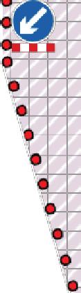
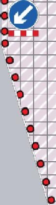
99

100
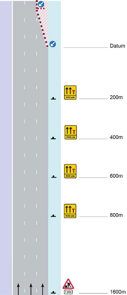
101
102 OPERATIONAL ISSUES U7.6 THE ALTERNATIVE ENTRY TAPER APPLICATION AND USE U7.6.1 The alternative entry taper layout described below may be used, subject to appropriate risk assessment and where conditions are considered suitable, as a direct replacement for the relaxation scheme entry taper shown in Part 1: Design, Plan DZB3. U7.6.2 The alternative entry taper layout may be used for relaxation scheme temporary traffic management at road works on dual carriageways where single or multiple lane closures are to be installed on the offside or nearside. U7.6.3 The alternative entry taper arrangement (shown in Figure 7.9) consists of five rows of cones placed perpendicular to the normal axis of travel at 27m centres. Each successive row in the direction of travel has one additional cone, with two intermediate cones placed at 9m centres between the perpendicular rows. Sequentially flashing road danger lamps are placed on the outer cones of each perpendicular row and on the intermediate cones between the perpendicular rows. This configuration is repeated in each lane closed. U7.6.4 The placement of cones at 9m centres allows the cones forming the alternative entry taper to be aligned with TSRGD Diagram or carriageway markings. Using the carriageway markings in this way as a template/baseline for alignment of the cones forming the alternative entry taper simplifies setup and enables more accurate cone placement. This layout does, however, result in a slightly shorter relaxation scheme entry taper of 135m (1 in 37) compared to the 150m (1 in 40) specified in Part 1 :Design Appendix A1, Table A1.3. This factor should be considered when applying the alternative entry taper. U7.6.5 Planning processes for the selection of taper type must give robust consideration to ensuring risk is adequately controlled for both road users and road workers. U7.6.6 Any decision to adopt the alternative entry taper layout should take account of the road conditions as set out in Part 1: Design, Paragraphs D1.6.3 and D1.6.5 and Section D3.8; and Part 2: Operations, Section O1.6. The definition of low traffic flows is as per Part 1: Design, Appendix A2.41. U7.6.7 If an appraisal of the aspects given in these sections indicates that the use of the alternative entry taper layout is inadvisable or inappropriate, the use of the entry taper layout shown in Part 1: Design, Plan DZB3 should be specified. This is shown for reference in Figure
103 OPERATIONAL ISSUES 50m 35m 108m 81m 54m 27m 0m 0m Figure 7.8 Relaxation scheme entry taper layout (from Plan DZB3) Figure 7.9 Alternative layout for an entry taper for relaxation scheme works on a dual carriageway 100
104 OPERATIONAL ISSUES U7.7 WORK SITE SIGNS AND SIGNALS U7.7.1 For works activities, adequate signing is required to highlight risks to workers within the works area and working space as identified in the specific risk assessment for the relevant work activities and as required by the Health and Safety (Safety Signs and Signals) Regulations Where signs are required for highlighting hazards not related to the movement of traffic in the works area, working space or adjacent carriageway these do not need to be designed as prescribed traffic signs (which includes cones, cylinders etc.). These signs should not be designed or placed on site in a manner which approaching traffic could interpret them as indicating a message, warning, restriction or requirement to road users. U7.7.2 Where signs are needed within the works area and working space to indicate to workers risks related to moving vehicles, then prescribed signs and equipment must be used if there is suitable method of signing the hazard using any prescribed sign or permitted variation. Only if there is no suitable sign, or combination of signs, which could be used to highlight the hazard should signs not prescribed in the Regulations, or authorised, be used; it is not acceptable to design or place signs of this nature in the works area or working space which could be seen as indicating a message, warning, restriction or requirement to approaching road users. U7.7.3 The design of the temporary traffic management may need to be adjusted so that work site signs which are not prescribed or authorised are not visible to road users e.g. placing them behind barriers or screens, or behind traffic signs, but are only visible to workers. Extra care must be taken if using any non-prescribed signs along the boundary of the working space and the safety zone. Unless signs or equipment are likely to be obscured from the view of workers it is recommended non-prescribed signs are set back from any live section of road e.g. the back of hard shoulder or on the verge. U7.7.4 Non-prescribed site safety signs should be kept separate from prescribed signs (particularly cones) and in no circumstances should they be used as substitutions for prescribed signs outside of the working space or works area. This includes all planned works and emergency traffic management. Non-prescribed work site signs used in this way would be an unlawful obstruction. Where off peak only works are being implemented, these signs must be not be left in view of road users e.g. on verges or in central reservations, when the TTM has been removed during peak periods. If needed, signs should be removed from site after the works have been completed and before the temporary traffic management is removed. U7.7.5 Workers must be adequately briefed or trained on how to access the worksite, on what hazards from vehicles in the works zone or working space may be present and how to exit the works safety. Signs (whether prescribed or not) are not sufficiently reliable to be the primary method of highlighting that a hazard is present on-site; signs should only be used to highlight the location of a hazard for which the worker is already aware. While work site signs should be considered as necessary to highlight hazards it is recommended that activities in the working area and works zone should be designed and undertaken so that the hazards would be obvious to workers, for example by directly lighting the hazard. U7.7.6 The design of the temporary traffic management should permit its safe installation, maintenance and removal using only prescribed or authorised traffic signs. Non-prescribed works site signs should not be needed to enable these types of activities to be undertaken. U7.7.7 Organisations undertaking works should review guidance and industry practice relating to work site signs. Where there are industry standard details and solutions for specific hazards e.g. overhead power cables and reduced headroom at structures, extra care should be taken if other methods of signing and highlighting are used. The comprehension of site signs should be reviewed particularly where the signs are symbolic; where nonstandard colours are used e.g. coloured cones, the impact of colour blindness and the differences in contrast, reflective and retroreflective performances of materials of different colour must be taken into account. 101
105 OPERATIONAL ISSUES U7.8 SCHEME INSPECTIONS U7.8.1 The requirements for inspecting schemes after installation, during works and after removal are given in Part 2: Operation Section O3. While it is recommended that formal records of these inspections are retained, if contractors wish to undertake works with the following features then records should be kept for a period of at least six months after the completion of the works: Mandatory reduced speed limits; Narrow lanes; Road marking and road stud surveys where warning lamps are omitted as identified in Section U2.14; Relaxations schemes with a reduced number of approach signs; Schemes where smaller signs than recommended in this Chapter are used; and Schemes with unlit signs in street light areas. U7.8.2 On completion of the works contactors are required to remove all signs and equipment, including any remote signs used to give advance warning. This should be recorded and audited against the initial inspection. 102
106
107 SIGN FACE DESIGN U8.3 NON-POLICE INCIDENT MANAGEMENT SIGNS U8.3.1 Guidance on the use of non-police equivalent of Diagram 829.1, and signs is given in Section U5.7 and sign design shown in Figure 8.2. The non-police USE HARD SHOULDER sign may only be deployed with the permission of a uniformed police officer or a traffic officer in uniform. These signs are to Schedule 13.9 and are white on blue. Figure 8.2 Non-police incident management signs 104
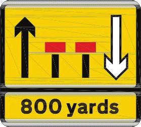
108
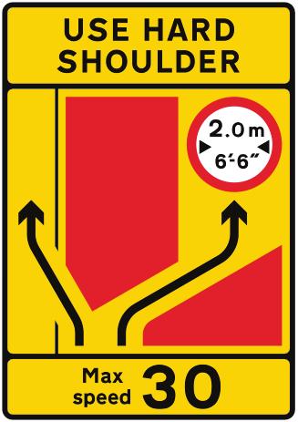
109

110 SIGN FACE DESIGN U8.6.6 The position of arrows and thus any text or roundels above the arrows, is generally fixed, making the design of these signs amenable to computerisation. Figure 8.5 Typical Diagram 7244 sign U8.6.7 The design of signs to Diagram 7245 must be in accordance with Working Drawing P7245. The part of the sign coloured yellow may be fluorescent yellow. For a typical design see Figure 8.6. Figure 8.6 Typical Diagram 7245 sign U8.6.8 These signs may be at one of four x heights 100, 125, 150 or 175mm, depending on the situation in which they are located. See Appendix A1. U8.6.9 Text and symbols may be added to the centre panel of these signs when they are used as temporary directional signs. The legend content is limited to a maximum of three lines of text. Regulatory signs are not permitted to be included on Diagram 7245 signs. U The centre panel is formed from a range of generally fixed shaped arrows and red blocks denoting areas of carriageway unavailable to traffic or the central reserve. The position of these blocks within the centre panel is fixed, making the design of these signs amenable to computerisation. U Signs to Diagram 7244 must be used to replace those equivalent TSRGD 2002 Diagram numbers 7201 and , where those signs appear or are mentioned in Part 1 or Part 2. U Signs to Diagram 7245 must be used to replace those equivalent TSRGD 2002 Diagram numbers 7203 to 7205 inclusive and 7207 to 7256 inclusive, where those signs appear or are mentioned in Part 1 or Part
111 SIGN FACE DESIGN U Where a TSRGD 2002 sign shows both text and a regulatory roundel above a cranked arrow, separate signs to Diagrams 7244 and 7245 should be provided instead. This will help to ensure that the resulting signs present no manual handling/installation issues and ease driver comprehension due to the reduced legend content of each individual sign. Where separate signs are provided, the order in which they are displayed to drivers should be: 7244 bearing destination information; 7244 bearing regulatory information; or Note: A minimum of one pair of each type of 7244 sign will be needed when both destination and regulatory information is displayed. Where a lane change zone plan shows four pairs of signs, the first two pairs of signs should bear destination information. Regulatory information will then be displayed on the next pair of signs if necessary. As there will generally be further signs to Diagram 7244 throughout the works showing the remaining distance of restrictions, it is more important to emphasise lane destinations in the lane change zone than lane restrictions. U8.7 AMENDMENTS TO TRAFFIC SIGNS IN LANE CHANGE LAYOUTS U8.7.1 Based on the guidance given in this document the following examples show typical changes to Part 1: Design, DZ series layout plans. U8.7.2 Main changes to Diagram numbers are: 7252, 7256 are replaced with Diagram 508.1; 7253 is replaced with Diagram 509.1; 7201, , 7263, 7264, 7271 are replaced with Diagram 7244; 7203, , 7204, 7205, 7209, 7210, 7212, 7215, 7216, 7230, 7231, 7235, 7237, 7260, 7261, 7263, 7264, 7271, 7272 are replaced with Diagram U8.7.3 Header and footer panels previously numbered as Diagrams 7263 and/or 7271 can be incorporated into Diagrams 7244 and U8.7.4 The keys to the plans are given in Part 1: Design: Appendix 1, Tables A1.4 and A1.5 which show DZ revised layouts: DZC4 Lead-in zone for a single-lane changeover onto the hard shoulder; DZC8 Lead-in zone for a three-lane crossover with narrow lanes; DZC9 Lead-in zone for splitting lanes for a changeover onto the hard shoulder and a single-lane crossover; DZD3 Works zone showing a buffer lane; DZD5 Works zone showing narrow lanes; DZD7 Works zone including a junction (secondary carriageway); DZE6 End-of-work zone for a two-lane return crossover with a single-lane changeover from the hard shoulder. 108


112 SIGN FACE DESIGN DZC4: Lead-in zone for a single-lane changeover onto the hard shoulder DZC8: Lead-in zone for a three-lane crossover with narrow lanes 109

113 SIGN FACE DESIGN DZC9: Lead-in zone for splitting lanes for a changeover onto the hard shoulder and a single-lane crossover 110


114 SIGN FACE DESIGN DZD3: Works zone showing a buffer lane DZD5: Works zone with narrow lanes 111

115 SIGN FACE DESIGN DZD7: Works zone including a junction (secondary carriageway) 112

116 SIGN FACE DESIGN Plan DZE6: End-of-works zone for a two-lane return crossover with a single-lane changeover from the hard shoulder 113
117 SIGN FACE DESIGN U8.7.5 Based on the guidance given in this document the following examples show typical changes to the DTF series layout plans provided in Part 1: Design: DTF1 Tidal flow layout, lead-in zone for full contra-flow on a two-lane carriageway road (primary direction); DTF2 Tidal flow layout, lead-in zone for full contra-flow on a two-lane carriageway road (secondary direction). U8.7.6 Main changes to Diagram numbers are: 7201, 7238, 7263, 7271 are replaced with Diagram 7244; 7201, 7203, , 7204, 7209, 7210, 7215, 7230, 7231, 7232, 7238, 7260, 7261, 7263, 7271 are replaced with Diagram

118 SIGN FACE DESIGN Plan DTF1: Tidal flow layout, lead-in zone for full contra-flow on a two-lane carriageway road (primary direction) Note: *indicates where a sign is required for one condition but not for the other; and should be covered or removed then not required. 115

119 SIGN FACE DESIGN Plan DTF2: Tidal flow layout, lead-in zone for full contra-flow on a two-lane carriageway road (secondary direction) Note: *indicates where a sign is required for one condition but not for the other; and should be covered or removed then not required. 116
Chapter 8 (2009) - Summary of key changes
 - Summary of key changes") Chapter 8 (2009) - Summary of key changes (Some sections and paragraphs in the revised edition have been renumbered to take account of new sections and paragraphs; section numbers below refer to the revised
Chapter 8 (2009) - Summary of key changes (Some sections and paragraphs in the revised edition have been renumbered to take account of new sections and paragraphs; section numbers below refer to the revised
Aiming for Zero Road Worker Safety. Mark Pooley Highways Agency Road Worker Safety Programme Manager Monday 11 June 2012
 Aiming for Zero Road Worker Safety Mark Pooley Highways Agency Road Worker Safety Programme Manager Monday 11 June 2012 1. Road Worker Safety Strategy. RWS Strategic Target No. 1: achieve a substantial
You can download the latest version of this Traffic Signs Manual chapter and all other Traffic Signs Manual chapters from:
 NOTE: You can download the latest version of this Traffic Signs Manual chapter and all other Traffic Signs Manual chapters from: http://tsrgd.co.uk/documents/traffic-signs-manual Traffic Signs Manual CHAPTER
INTERIM ADVICE NOTE 188/16
 INTERIM ADVICE NOTE 188/16 Guidance on Omission of Warning Lights (Road Danger Lamps) for Relaxation Works on Dual Carriageways Summary Guidance for omission of warning lights (road danger lamps) in temporary
You can download the latest version of this Traffic Signs Manual chapter and all other Traffic Signs Manual chapters from:
 NOTE: You can download the latest version of this Traffic Signs Manual chapter and all other Traffic Signs Manual chapters from: http://tsrgd.co.uk/documents/traffic-signs-manual Traffic Safety Measures
CONTROL AND COMMUNICATIONS PROVISION PART 1 TD 46/05 MOTORWAY SIGNALLING SUMMARY
 DESIGN MANUAL FOR ROADS AND BRIDGES VOLUME 9 SECTION 1 NETWORK - TRAFFIC CONTROL AND COMMUNICATIONS STANDARDS OF PROVISION PART 1 TD 46/05 MOTORWAY SIGNALLING SUMMARY This issue of TD 46 incorporates Interim
DRAFT INTERIM ADVICE NOTE 150/17
 DRAFT INTERIM ADVICE NOTE 150/17 Guidance on Alternative Temporary Traffic Management Techniques for Relaxation Works on Dual Carriageways Summary Guidance for temporary traffic management (TTM), on the
Design and Installation of Low Level Cycle Signals
 Transport for London Surface Transport Management System Document Guidance Note Design and Installation of Low Level Cycle Signals Document reference: SQA-0651 - Issue: Draft out of date information. 1
INTERIM ADVICE NOTE 150/14 Revision 02. Guidance on Alternative Temporary Traffic Management Techniques for Relaxation Works on Dual Carriageways
 INTERIM ADVICE NOTE 150/14 Revision 02 Guidance on Alternative Temporary Traffic Management Techniques for Relaxation Works on Dual Carriageways Summary Guidance for temporary traffic management (TTM),
Generic Safe Method for placing TTM on MM-ALR
 Summary 1. This paper describes a generic safe method for setting up and taking down Temporary Traffic Management (TTM) on Managed Motorway All Lane Running (MM-ALR) schemes. 2. An understanding of how
Q&A for Safety Code. Prepared by the HAUC-UK Safety Code working group
 Q&A for Safety Code Prepared by the HAUC-UK Safety Code working group 1 What is the latest version of the Safety Code? At the time of writing, the last time any amendments were made to the Safety Code
INTERIM ADVICE NOTE 150/12. Guidance for Alternative Temporary Traffic Management Techniques for Relaxation Schemes on Dual Carriageways.
 INTERIM ADVICE NOTE 150/12 Guidance for Alternative Temporary Traffic Management Techniques for Relaxation Schemes on Dual Carriageways Summary Guidance for temporary traffic management (TTM), on the approach
Q&A for Safety Code. Prepared by the HAUC-UK Safety Code working group
 Q&A for Safety Code Prepared by the HAUC-UK Safety Code working group 1 What is the latest version of the Safety Code? At the time of writing, the last time any amendments were made to the Safety Code
Temporary Vehicle Restraint System Policy
 Temporary Vehicle Restraint System Policy Prepared By; J Wilkinson H&S Manager, Civils Prepared for: Installation of TVRS on all triio highways projects including JV s. Page 1 of 8 Contents 1.0 Introduction
Essential Standard No. 16. Streetworks - Short duration static works carried out from a vehicle
 Key Messages Short duration static works must not exceed 60 mins, including setting up and dismantling traffic management. A vehicle or vehicles should be used whenever possible to protect the workforce.
Traffic Calming Regulations
 Traffic Advisory Leaflet 7/93 August 1993 Traffic Calming Regulations Introduction Traffic calming can help drivers to make their speeds appropriate to local conditions, through measures which are self-enforcing.
Draft letter to Designers and Managing Agents INTERIM ADVICE NOTE 43/02: CANTILEVER AND PORTAL GANTRY VMS
 Draft letter to Designers and Managing Agents INTERIM ADVICE NOTE 43/02: CANTILEVER AND PORTAL GANTRY VMS This Interim Advice Note announces amendments to a series of guidelines related to cantilever and
GUIDANCE FOR TEMPORARY TRAFFIC MANAGEMENT AT SURFACE DRESSING SITES
 GUIDANCE FOR TEMPORARY TRAFFIC MANAGEMENT AT SURFACE DRESSING SITES Formerly known as the CSS/ RSDA Code of Practice Published by RSTA and ADEPT December 2017 Forward Whilst ADEPT and RSTA understands
Interim Advice Note 115/08, Revision 1. Requirements and Guidance for Works on the Hard Shoulder and Road Side Verges on High Speed Dual Carriageways
 Interim Advice Note 115/08,. Requirements and Guidance for Works on the Hard Shoulder and Road Side Verges on High Speed Dual Carriageways Summary Requirements and guidance for works on the hard shoulder
Q&A for Safety Code. Prepared by the HAUC-UK Safety Code working group
 Q&A for Safety Code Prepared by the HAUC-UK Safety Code working group Q1 What is the latest version of the Safety Code? The last time any amendments were made to the Safety Code was in June 2014. This
Chicane Schemes. Traffic Advisory Leaflet 12/97 December Introduction
 Traffic Advisory Leaflet 12/97 December 1997 Chicane Schemes Introduction Traffic Advisory Leaflet 9/94 "Horizontal Deflections" reported on the results of track trials carried out by the Transport Research
INTERIM ADVICE NOTE 150/11. Temporary Traffic Management Signing: Simplification of lane change zone signing for relaxation schemes.
 INTERIM ADVICE NOTE 150/11 Temporary Traffic Management Signing: Simplification of lane change zone signing for relaxation schemes Summary Guidance to those planning traffic management on omission of certain
Traffic calming regulations (Scotland)
") Traffic Advisory Leaflet 11/94 December 1994 Traffic calming regulations (Scotland) Introduction Traffic calming can help drivers to make their speeds appropriate to local conditions, through measures
Traffic Advisory Leaflet 11/94 December 1994 Traffic calming regulations (Scotland) Introduction Traffic calming can help drivers to make their speeds appropriate to local conditions, through measures
You can download the latest version of this Traffic Signs Manual chapter and all other Traffic Signs Manual chapters from:
 NOTE: You can download the latest version of this Traffic Signs Manual chapter and all other Traffic Signs Manual chapters from: http://tsrgd.co.uk/documents/traffic-signs-manual Traffic Signs Manual C
Introduction to the NRA Design Manual for Roads and Bridges
 Volume 0 Section 0 Part A 0.0.A Introduction to the NRA Design Manual for Roads and Bridges July 2011 St. Martin s House, Waterloo Road, Dublin 4. Tel:+353 1 660 2511 Fax +353 1 668 0009 Email : info@nra.ie
Cycle traffic and the Strategic Road Network. Sandra Brown, Team Leader, Safer Roads- Design
 Cycle traffic and the Strategic Road Network Sandra Brown, Team Leader, Safer Roads- Design Highways England A Government owned Strategic Highways Company Department for Transport Road Investment Strategy
Safety at Street Works and Road Works
 Safety at Street Works and Road Works A Code of Practice issued by the Secretary of State for Transport, the Scottish Executive and the National Assembly for Wales under sections 65 and 124 of the New
Roads and public rights of way
 Roads and public rights of way This factsheet outlines how the effects of the Proposed Scheme on roads and public rights of way (PRoW) along the line of route would be managed. Version 1.0 Last updated:
PART 5 TD 51/17 SUMMARY
 DESIGN MANUAL FOR ROADS AND BRIDGES VOLUME 6 SECTION 3 ROAD GEOMETRY HIGHWAY FEATURES PART 5 TD 51/17 SEGREGATED LEFT TURN LANES AND SUBSIDIARY DEFLECTION ISLANDS AT ROUNDABOUTS SUMMARY This document sets
QLDC Council 29 October Report for Agenda Item: 3
 QLDC Council 29 October 2015 Department: Infrastructure Beach Street Pedestrianisation Purpose Report for Agenda Item: 3 1 The purpose of this report is to obtain Council approval to consult over options
// RoWSaF Making roads safer for road workers rowsaf.org.uk. RoWSaF Strategy 2015
 // RoWSaF Making roads safer for road workers rowsaf.org.uk Working in partnership with clients, industry and key stakeholders to improve worker safety Often working close to live traffic, activities conducted
Design Measures taken, or being taken to eliminate or reduce the hazard
 Part B: CDM 2007 MMFD Procedures Hazard Elimination and Management Schedule Project Title: Managed Motorways All Lanes Running (MM-ALR) Job No.: 1039092 Design Discipline: IAN161/12 Prepared By: Emma Clutterbuck
TEMPORARY TRAFFIC CONTROL GUIDELINES FOR HIGHWAY-RAIL GRADE CROSSINGS
 TEMPORARY TRAFFIC CONTROL GUIDELINES FOR HIGHWAY-RAIL GRADE CROSSINGS 1.0 INTRODUCTION 1.1 Purpose The Southern California Regional Rail Authority (SCRRA) is the designated track owner of the Metrolink
USE OF SPEED AND RED LIGHT CAMERAS FOR TRAFFIC ENFORCEMENT: GUIDANCE ON DEPLOYMENT, VISIBILITY AND SIGNING
 USE OF SPEED AND RED LIGHT CAMERAS FOR TRAFFIC ENFORCEMENT: GUIDANCE ON DEPLOYMENT, VISIBILITY AND SIGNING INTRODUCTION 1. Safety cameras provide a valuable and cost-effective method of preventing, detecting
GUIDELINES FOR EMERGENCY TRAFFIC CONTROL
 GUIDELINES FOR EMERGENCY TRAFFIC CONTROL TABLE OF Contents Page Introduction...1 Chapter 6I of the 2009 MUTCD...2 Reason for Control...6 Components of Incident Management Area...7 Traffic Control Devices
Entry Treatments. Traffic Advisory Leaflet 2/94 August Introduction. Design. Vertical Deflections. Locations
 Traffic Advisory Leaflet 2/94 August 1994 Entry Treatments Introduction Entry treatments have been developed for use at side roads so that drivers leaving a major road are in no doubt that they are entering
Health & Safety Policy & Plan. Rightway Roofing.
 Health & Safety Policy & Plan. Rightway Roofing. Valid: 02/2012-02/2013 Contents ( 1 ) Policy Statement. ( 2 ) Hazard Identification. ( 3 ) Hazard Management. ( 4 ) Induction & Training. ( 5 ) Monitoring
INTERIM ADVICE NOTE 144/16 DIRECTIONAL SIGNS ON MOTORWAY AND ALL-PURPOSE TRUNK ROADS GRADE SEPARATED JUNCTIONS
 INTERIM ADVICE NOTE 144/16 DIRECTIONAL SIGNS ON MOTORWAY AND ALL-PURPOSE TRUNK ROADS GRADE SEPARATED JUNCTIONS Summary This document sets out guidance for the use of directional signs at motorway and allpurpose
TSRGD Consultation: Highways Agency Safe Road Design Team response.
 TSRGD Consultation: Highways Agency Safe Road Design Team response. 1. Summary While continuing to support the principles of revising the regulations the Agency notes the number of inconsistences in the
INTERIM ADVICE NOTE 93/07 DRIVER LOCATION SIGNS INTERIM PERFORMANCE SPECIFICATION
 INTERIM ADVICE NOTE 93/07 DRIVER LOCATION SIGNS INTERIM PERFORMANCE SPECIFICATION IAN 93/07 Page 1 of 10 Apr 2007 . for. Interim Advice Note 93/07 The following requirements shall apply until further notice.
DESIGN CODE. Enterprise West Harlow London Road North Design Code 21
 DESIGN CODE Enterprise West Essex @ Harlow London Road North Design Code 21 4 MAXIMUM BUILDING HEIGHTS 4.1 Table 4A sets out maximum building height standards for each character area within the LDO boundary.
Traffic Calming Policy
 Article I. Purpose and Goal. The purpose of this policy is to establish criteria and procedures the City will use to evaluate requests for, and if appropriate, implement traffic calming measures. Neighborhood
Issues at T junctions:
 TheSlade_PublicConsulationPlans_March2017.pdf These comments relate to junction designs in this phase of the project on The Slade. Comments begin with the northernmost junction: Girdlestone Rd and continue
The Work at Height Regulations 2005 A brief guide
 The Work at Height Regulations 2005 A brief guide In 2003/04 falls from height accounted for 67 fatal accidents at work and nearly 4000 major injuries. They remain the single biggest cause of workplace
MINE SAFETY TARGETED ASSESSMENT PROGRAM. Ground or strata failure NSW metalliferous mines. April
 MINE SAFETY TARGETED ASSESSMENT PROGRAM Ground or strata failure NSW metalliferous mines April 2017 www.resourcesandenergy.nsw.gov.au Document control Publication title: Ground or strata failure NSW metalliferous
Bramshaw traffic calming proposal
 - 1 - Bramshaw traffic calming proposal Initial options appraisal report July 2017 - 2-1. Project background Hampshire Country Council has commissioned Test Valley Borough Council to carry out an option
NRA MANUAL OF CONTRACT DOCUMENTS FOR ROAD WORKS
 Volume 0 Section 0 Part 1 NRA SD 01/13 NRA MANUAL OF CONTRACT DOCUMENTS FOR ROAD WORKS Introduction to the NRA Manual of Contract Documents for Road Works March 2013 St. Martin s House, Waterloo Road,
Smart motorways: all lane running on the M25. Guidance for EEAST crews
 Smart motorways: all lane running on the M25 Guidance for EEAST crews Published April 2014 Background This month (April 2014) the Highways Agency launched its smart motorways, which make use of new technology
MARINE SAFETY PLAN
 PORT MARINE SAFETY CODE MARINE SAFETY PLAN 2015-2017 Introduction As required at article 3.20 of the Port Marine Safety Code (PMSC), the Port of London Authority (PLA) publishes its Marine Safety Plan
Examples of pressure systems and equipment are:
 Pressure systems Safety and you Introduction If pressure equipment fails in use, it can seriously injure or kill people nearby and cause serious damage to property. Each year in Great Britain, there are
The Work at Height Regulations 2005 A brief guide
 Off work sick and worried about your job? Steps you can take to help your return to work The Work at Height Regulations 2005 A brief guide Health and Safety Executive 1 In 2003/04 falls from height accounted
Extending 200m either side of the intersection Te Mata Mangateretere/ Waimarama/ Te Mata/River Rd
 RCA consent (eg CAR/WAP) and/or RCA contract reference TRAFFIC MANAGEMENT PLAN (TMP) FULL FORM Use this form for complex activities. Refer to the NZ Transport Agency s Traffic control devices manual, part
NRA MANUAL OF CONTRACT DOCUMENTS FOR ROAD WORKS. Introduction to the NRA Manual of Contract Documents for Road Works. Volume 0 Section 0 Part 1
 Volume 0 Section 0 Part 1 NRA SD 01/12 NRA MANUAL OF CONTRACT DOCUMENTS FOR ROAD WORKS Introduction to the NRA Manual of Contract Documents for Road Works February 2012 St. Martin s House, Waterloo Road,
CHAPTER 2F. TOLL ROAD SIGNS. Table 2F-1. Toll Road Sign and Plaque Minimum Sizes
 2011 Edition Page 249 Section 2F.01 Scope CHAPTER 2F. TOLL ROAD SIGNS 01 Toll highways are typically limited-access freeway or expressway facilities. A portion of or an entire route might be a toll highway,
Local Highway Panels Members Guide. 2 Speed and Traffic Management
 Local Highway Panels Members Guide 2 Speed and Traffic Management 2 Local Highway Panels (LHP) Members Guide 2016/17 1. Introduction Following the publication of the DfT guidance on setting local speed
1 This technical note considers the issues associated with the use of tidal flow bus lanes on key public transport corridors in Cambridge.
 TECHNICAL NOTE: TIDAL FLOW BUS LANE OPTION ASSESSMENT Purpose 1 This technical note considers the issues associated with the use of tidal flow bus lanes on key public transport corridors in Cambridge.
INTERIM ADVICE NOTE 171/12. Risk Based Principal Inspection Intervals
 INTERIM ADVICE NOTE 171/12 Risk Based Principal Inspection Intervals Summary This Interim Advice Note sets out the requirements and guidance for service providers using risk based inspection intervals.
Economic and Social Council
 UNITED NATIONS E Economic and Social Council Distr. GENERAL TRANS/WP.1/2003/3/Rev.4 23 April 2004 ENGLISH Original: ENGLISH, FRENCH and RUSSIAN ECONOMIC COMMISSION FOR EUROPE INLAND TRANSPORT COMMITTEE
Welsh Government Trunk Road Maintenance Manual
 Welsh Government Trunk Road Maintenance Manual into Value for Money of Motorway and Trunk Road Investment. the Welsh Government's specification 'Trunk Road Maintenance Manual' (TRMM). This. 11 Materials,
Traffic Assets Section Proposed Removal of Street Lighting Road Safety Review Report No 48
 Street Lighting Section Unique Reference: o. 48 Traffic Assets Section Report o 48 Reviewer: Ellie Briggs, BEng (Hons) CEng MICE Highway Classification / umber Road / Street ame: District / Settlement:
CHECKLIST 2: PRELIMINARY DESIGN STAGE AUDIT
 CHECKLIST 2: PRELIMINARY DESIGN STAGE AUDIT 2.1 General topics 2.1.1 Changes since previous audit Do the conditions for which the scheme was originally designed still apply? (for example, no changes to
UK Contractors Group Mobile Elevating Work Platforms Good Practice Toolkit June June 2015 Page 1 of 16
 UK Contractors Group Mobile Elevating Work Platforms Good Practice Toolkit www.ukcg.org Page 1 of 16 Contents Foreword Reference Material Initial Considerations Planning and Preparation for MEWP Activities
1.0 PURPOSE 2.0 REFERENCES
 Page 1 1.0 PURPOSE 1.1 This Advisory Circular provides Aerodrome Operators with guidance for the development of corrective action plans to be implemented in order to address findings generated during safety
Australian Standard. Manual of uniform traffic control devices. Part 3: Traffic control for works on roads AS AS 1742.
 AS 1742.3 2009 AS 1742.3 2009 Australian Standard Manual of uniform traffic control devices Part 3: Traffic control for works on roads This Australian Standard was prepared by Committee MS-012, Road Signs
Raised Rib Markings. Traffic Advisory Leaflet 2/95 March Introduction
 Traffic Advisory Leaflet 2/95 March 1995 Raised Rib Markings Introduction Raised rib markings consist of a continuous line marking with ribs across the line at regular intervals. They were first specially
Highways England Creative M Welcome. Smart motorway M6 junctions 16 to 19 public information exhibition
 Welcome Smart motorway junctions 16 to 19 public information exhibition Smart motorway junctions 16 to 19 Making the motorway better The is also part of the Highways England strategic road network connecting
Know Your TRAFFIC SIGNS. Official Edition. London: TSO
 Know Your TRAFFIC SIGNS Official Edition London: TSO Department for Transport Great Minster House 76 Marsham Street London SW1P 4DR Telephone 020 7944 8300 Web site www.dft.gov.uk www.direct.gov.uk/travelandtransport
Our Approach to Managing Level Crossing Safety Our Policy
 Our Approach to Managing Level Crossing Safety Our Policy Our policy towards managing level crossing risk is: that we are committed to reducing the risk at level crossings where reasonably practicable
HEAT, COLD, SOLAR ULTRAVIOLET & INCLEMENT WEATHER
 CONTRACTOR WHS HAZARD STANDARD HEAT, COLD, SOLAR ULTRAVIOLET & INCLEMENT WEATHER EXTERNAL USE ONLY Principles in the Optus Contractor WHS management process CONTRACTOR MANAGEMENT STAGES PRINCIPLES THIS
(2) but does not include a shaft, trench or tunnel that is a mine or is part of the workings of a mine.
 but does not include a shaft, trench or tunnel that is a mine or is part of the workings of a mine.") Health and Safety Procedure - Confined Spaces Section 1 - Background and Purpose (1) Confined spaces are, for the purposes of this procedure, defined as the following which is the definition under the
Health and Safety Procedure - Confined Spaces Section 1 - Background and Purpose (1) Confined spaces are, for the purposes of this procedure, defined as the following which is the definition under the
London Organising Committee of the Olympic Games and Paralympic Games. 14 June 2010
 London Organising Committee of the Olympic Games and Paralympic Games 14 June 2010 London 2012 Olympic and Paralympic Games Volunteer Protocol Title This document shall be known as the London 2012 Olympic
Cyclists at road narrowings
 Traffic Advisory Leaflet 1/97 February 1997 Cyclists at road narrowings Introduction Traffic calmed streets can offer a more attractive environment for cycling, by reducing motor vehicles speeds to a level
LADDERS FIXED AND PORTABLE
 CONTRACTOR WHS HAZARD STANDARD LADDERS FIXED AND PORTABLE EXTERNAL USE ONLY Principles in the Optus Contractor WHS management process CONTRACTOR MANAGEMENT STAGES PRINCIPLES THIS STANDARD REQUISITION Requisition
Streets for All : 9 Use of white lines
 Streets for All : 9 Use of white lines On 1st April 2015 the Historic Buildings and Monuments Commission for England changed its common name from English Heritage to Historic England. We are now re-branding
Traffic signs used, including signs giving orders, warning signs, direction signs, information signs and road works signs.
 Traffic signs Traffic signs used, including signs giving orders, warning signs, direction signs, information signs and road works signs. Although The Highway Code shows many of the signs commonly in use,
PART 5 TD 51/03 SEGREGATED LEFT TURN LANES AND SUBSIDIARY DEFLECTION ISLANDS AT ROUNDABOUTS SUMMARY
 DESIGN MANUAL FOR ROADS AND BRIDGES VOLUME 6 SECTION 3 ROAD GEOMETRY HIGHWAY FEATURES PART 5 TD 51/03 SEGREGATED LEFT TURN LANES AND SUBSIDIARY DEFLECTION ISLANDS AT ROUNDABOUTS SUMMARY This document sets
AT403.1 Ancient monument Note 3 amended P500 Basic triangle New size 1800mm added
 AT403.1 P666 P874 P1028.4 P2509.1 P5001.2 P500 P672 P875 P1032 P2511.1 P5010 P530A P673 P876 P1033 P2512.1 P5011 P530.1 P784.1 P877 P1050 P2601.1 P7005 P543 P786 P878 P2010.1 P2601.1A P7009.1 P563.1 P787
MUTCD Part 6G: Type of Temporary Traffic Control Zone Activities
 MUTCD Part 6G: Type of Temporary Traffic Control Zone Activities 6G.01 Typical Applications Each temporary traffic control (TTC) zone is different. Many variables, such as location of work, highway type,
Becoming a Road Safety Auditor
 Becoming a Road Safety Auditor Becoming a Road Safety Auditor 1 Road Safety Auditing The route to being part of the Audit Team To start: The main requirements for someone to become a Road Safety Auditor
Report to Cabinet. 18 May 2016
 Agenda Item 8 Report to Cabinet 18 May 2016 Subject: Presenting Cabinet Member: Proposed CCTV Enforcement of Traffic Contraventions in a Bus Lane (Key Decision Ref. No. HE030) Highways and Environment
CONSTRUCTION SPECIFICATION
 CAPRICORN MUNICIPAL DEVELOPMENT GUIDELINES CONTROL OF TRAFFIC C201 CONSTRUCTION SPECIFICATION CAPRICORN MUNICIPAL DEVELOPMENT GUIDELINES C201 ISSUE: NO:1 October 2007 TABLE OF CONTENTS CLAUSE CONTENTS
The Use of Variable Message Signs on All-Purpose and Motorway Trunk Roads
 THE HIGHWAYS AGENCY THE SCOTTISH OFFICE DEVELOPMENT DEPARTMENT THE WELSH OFFICE Y SWYDDFA GYMREIG THE DEPARTMENT OF THE ENVIRONMENT FOR NORTHERN IRELAND The Use of Variable Message Signs on All-Purpose
Aerodrome Safeguarding Airside Operational Instruction 16. AOI Owner - Operations Developments & Safety Manager
 AOI Owner - Operations Developments & Safety Manager 1. Assessment and Treatment of Obstacles 1.1 Obstacles are surveyed in accordance with the requirements of CAP 232 Aerodrome Survey Requirements and
The Highways Agency is working to improve the M1 between junction 28 (near Alfreton) and junction 35a (the A616 Stocksbridge bypass).
 and junction 35a (the A616 Stocksbridge bypass).") Welcome The Highways Agency is working to improve the M1 between junction 28 (near Alfreton) and junction 35a (the A616 Stocksbridge bypass). The M1 is a vital part of the strategic road network, connecting
Welcome The Highways Agency is working to improve the M1 between junction 28 (near Alfreton) and junction 35a (the A616 Stocksbridge bypass). The M1 is a vital part of the strategic road network, connecting
SARF Engineering for Road Safety
 SARF Engineering for Road Safety 1 Road Traffic Signs Manual & Legislation National Road Traffic Act, Act 93 of 1996 National Regulations 2000 SADC and SA Road Traffic Signs Manuals No. Title SADCRTSM
CITY OF SAINT JOHN TRAFFIC CALMING POLICY
 CITY OF SAINT JOHN TRAFFIC CALMING POLICY VERSION: 1.0 April 10, 2012 Pedestrians, Cyclists and Motorists Sharing Street Spaces CONTENTS INTRODUCTION... 3 POLICY GOAL... 3 POLICY OBJECTIVES... 3 GUIDING
OPERATIONS CONTRACT MANAGEMENT MEMO CMM xx/16
 OPERATIONS CONTRACT MANAGEMENT MEMO CMM xx/16 SUBJECT: CARRIAGEWAY CROSSING AND LIVE LANE WORKING - CLARIFICATION Date Issued: (to be inserted by Operations Central, Directorate Services Team) Enquiry
Industry Consultation Paper
 Industry Consultation Paper Proposed amendments to the European Communities (Carriage of Dangerous Goods by Road and Use of Transportable Pressure Equipment) Regulations 2011 to 2015 concerning Pressure
CHAPTER 2G. PREFERENTIAL AND MANAGED LANE SIGNS
 2011 Edition - Revision 2 Page 275 Section 2G.01 Scope CHAPTER 2G. PREFERENTIAL AND MANAGED LANE SIGNS 01 Preferential lanes are lanes designated for special traffic uses such as high-occupancy vehicles
Horizontal Directional Drilling and Impact Moling
 THE INSTITUTION OF GAS ENGINEERS Safety Recommendations Founded 1863 IGE/SR/26 Royal Charter 1929 Communication 1662 Patron Her Majesty The Queen Horizontal Directional Drilling and Impact Moling President:
1. TSRGD 2015 rewrite clarification and details
 Question 13: The following issues need to be considered in the rewrite of TSRGD. These issues 1. clarify points of detail within the TSRGD rewrite 2. or provide additional signage to measures already approved
LONE WORKING HEALTH AND SAFETY GUIDANCE
 LONE WORKING HEALTH AND SAFETY GUIDANCE Revised March 2017: Version 3.1 Name of Policy: Purpose of the Policy: Policy Applies to: Approved by: Responsible for its Updating: Final Approval by: Lone Working
MUTCD Part 6D: Pedestrian and Worker Safety
 MUTCD Part 6D: Pedestrian and Worker Safety Section 6D.01 Pedestrian and Worker Safety The needs and control of all road users (motorists, bicyclists, and pedestrians) within the highway, including persons
WORK ZONE TRAFFIC CONTROL PROCEDURES
 WORK ZONE SETUP / REMOVAL WORK ZONE TRAFFIC CONTROL PROCEDURES When installing a work zone, install the advance warning signs on all approaches prior to installing the traffic control devices. Perform
Appendix 12 Parking on footways and verges
 Appendix 12 Parking on footways and verges Legal position Parking on footways and verges whether wholly or partly is banned throughout London, unless signs are placed to allow parking. The ban requires
Welcome. Smart motorway M1 junctions 13 to 16 public information exhibition. Highways England Creative [XXXXX_XXXX_XXX]
![Welcome. Smart motorway M1 junctions 13 to 16 public information exhibition. Highways England Creative [XXXXX_XXXX_XXX]](/thumbs/95/124397560.jpg "Welcome. Smart motorway M1 junctions 13 to 16 public information exhibition. Highways England Creative [XXXXX_XXXX_XXX]") Welcome Smart motorway junctions 13 to 16 public information exhibition Smart motorways Smart motorways are a technology driven approach to the use of our motorways, increasing capacity and relieving congestion
Welcome Smart motorway junctions 13 to 16 public information exhibition Smart motorways Smart motorways are a technology driven approach to the use of our motorways, increasing capacity and relieving congestion
LEVEL 2 CERTIFICATE OF COMPETENCE IN THE SAFE USE OF MOWERS ASSESSMENT SCHEDULE
 NPTC Registered Charity No. 1096429 STONELEIGH PARK, WARWICKSHIRE CV8 2LG Tel: 024 7685 7300 Fax: 024 7669 6128 Email: information@nptc.org.uk LEVEL 2 CERTIFICATE OF COMPETENCE IN THE SAFE USE OF MOWERS
A465 Heads of the Valleys Dualling Sections 5 and 6 Dowlais Top to Hirwaun SUMMARY PROOF OF EVIDENCE. Highways Engineering Document WG 1.3.
 A465 Heads of the Valleys Dualling Sections 5 and 6 Dowlais Top to Hirwaun SUMMARY PROOF OF EVIDENCE Highways Engineering Document WG 1.3.2 by Jonathan Thirkettle MARCH 2018 1. Introduction 1.1 I am Jonathan
Managed Motorways Experience from the UK
 Managed Motorways Experience from the UK Author David Kamnitzer (dkamnitzer@ibigroup.com) Director, IBI Group Project Manager of IBI Group s technical advisor commission for the Highways Agency s Managed
Safe work method statements
 Information about Safe work method statements How to prepare and use a safe work method statement (SWMS) for high risk construction work (HRCW) and who needs to prepare one. October 2018 Key concepts Hazard