This page intentionally left blank
|
|
|
- Bryan Anderson
- 6 years ago
- Views:
Transcription
1
2 This page intentionally left blank
 is published by the South Carolina Department of Transportation (SCDOT) Traffic Engineering Division.")
3 Revision Date April 25, 2008 June 20, 2008 July 28, 2008 August 18, 2008 November 13, 2009 August 18, 2011 Sept 26, 2012 April 27, 2015 ACCESS AND ROADSIDE MANAGEMENT STANDARDS 2008 Edition Access and Roadside Management Standards (ARMS Manual) is published by the South Carolina Department of Transportation (SCDOT) Traffic Engineering Division. This manual is not intended to present all of the information that is needed by a permittee or designer; however, this document does provide a majority of the information needed for encroachments onto the right-of-way of the SCDOT. For specific projects or specific design elements, the permittee or designer may need to reference other SCDOT or national publications to perform a fully comprehensive analysis of the project. As the need arises, this publication is revised, updated, and distributed within the Department. All parties are responsible for obtaining the most current edition. South Carolina Department of Transportation Traffic Engineering 955 Park Street, PO Box 191 Columbia, SC
4 This page intentionally left blank
5 ACCESS AND ROADSIDE MANAGEMENT STANDARDS 2008 EDITION Summary of Significant Changes In 1957, due to the enormous increase in the volume of traffic on the highway and the large number of accidents caused by unregulated entrances of highways, the South Carolina State Highway Department drafted Standards for Driveway Entrances to Highways. This publication was updated in 1976 and remained the standard until 1991 when the South Carolina Department of Transportation (SCDOT) published the Access and Roadside Management Standards, or ARMS Manual. It was updated in 1996 which is the edition that is currently being utilized. In 2004, Traffic Engineering identified the need for more comprehensive standards in step with current highway and land development practices in the region and nation. As a result, Traffic Engineering began a full scale update of the ARMS Manual. A committee was formed of representatives from Headquarters and District Traffic Engineering, Maintenance, Pre- Construction, and Hydrology to review the ARMS Manual and recommend changes to the current information and the addition of new concepts. The following items have been considered as the most significant changes to the manual. 1) Access Waivers (Chapter 1, Section 1E, Page 12): Recognizing that minimum criterion may not always be practical, a process has been established to approve exceptions to the access guidelines. If an applicant for an encroachment permit seeks a waiver, an access waiver request form (provided in Appendix C) shall be filled out and attached to the encroachment permit. The request should describe the undue hardship that will be placed on the applicant if a waiver is not granted. The Resident Maintenance Engineer (RME) should coordinate the waiver with the District Engineering Administrator and appropriate office at Headquarters. A waiver will only be granted if it is determined that: 1. Denial of the waiver will result in loss of reasonable access to the site. 2. The waiver is reasonably necessary for the convenience and welfare of the public. 3. All reasonable alternatives that meet the access requirements have been evaluated and determined to be infeasible. 4. Reasonable alternative access cannot be provided. 5. The waiver will not result in any violations of pedestrian accessibility in accordance with the ADAAG. When a waiver is approved, the reasons for granting the waiver and any recommendations given by the Department shall be clearly stated and included in the Department files. Restrictions and conditions on the scope of the permit should be imposed as required in order to keep potential safety hazards to a minimum. The encroachment permit may contain specific terms and conditions providing for the expiration of the waiver if in the future the grounds for the waiver no longer exist. An Access Waiver should be included in the Appeal Process Request detailed in Section 2E. 2) Driveway Classification (Chapter 3, Section 3A-1, Page 20): A classification system for driveways has been developed based on the number of trips that will be generated by the land use that the driveway serves. This classification system, shown in Table 3-3 (page 19) will guide the design of driveway elements including width and radii.
6 3) Driveway Spacing and Location (Chapter 3, Section 3C, Page 26): Driveway spacing requirements (Figure 3-7, Page 26) were increased based on current recommended practice in Transportation Research Board s Access Management Manual. However, the old spacing requirements have been retained for driveways located on roadways with AADT<2000. Rather than measuring the spacing from the centerline of the driveways as in the 1996 ARMS, spacing will now be measured from the near edge of the driveways. This method will provide adequate spacing regardless of a drive s geometry. In the case of large developments with outparcels, access for outparcels should be provided only internally; however, shared or individual driveways may be permitted provided twice the normal spacing requirements are met. 4) Access Placement in Interchange Areas (Chapter 3, Section 3C-4, Page 30): Access connections to crossroads in the vicinity of freeway interchanges has been addressed (Figure 3-11, Page 30). Minimum spacing between the on and off ramp termini and the first access point is defined. 5) School Access Design (Chapter 4, Page 35): SCDOT Traffic Engineering s Guidelines for School Transportation Design has been added as a new chapter to the manual. On-site stacking length requirements have been increased. 6) Street Intersections (Chapter 5, Page 41): Various elements of intersection design from the SCDOT Highway Design Manual have been summarized and added as a new chapter. These elements include intersection spacing, design vehicle considerations, approach grade and side slope, auxiliary lane design, and parking considerations. 7) Auxiliary Lanes (Chapter 5, Section 5D, Page 47): When adding turn lanes, the road should be brought up to the latest standards requiring the addition of 2 foot paved shoulders. 8) Traffic Impact Studies (Chapter 6, Page 53): A Traffic Impact Study is a specialized engineering study that evaluates the effects of proposed development on traffic conditions in an area. A chapter has been added describing when a traffic study is required and the information that should be contained in the study. 9) Sight Distance (Chapter 7, Page 59): The intersection sight distance section from the SCDOT Highway Design Manual has been added as a new chapter to this manual. This chapter will replace the sight distance tables from the 1996 ARMS.
7 ACCESS AND ROADSIDE MANAGEMENT STANDARDS 1 TABLE OF CONTENTS CHAPTER 1 INTRODUCTION A PURPOSE B AUTHORITY C SEVERABILITY D DEFINITIONS E DESIGN EXCEPTIONS AND ACCESS WAIVERS CHAPTER 2 ENCROACHMENT PERMITS A APPLICATION AND REQUIREMENTS B REVIEW AND APPROVAL C PERFORMANCE BONDS D CONDITIONS AND LIMITATIONS E ENCROACHMENT PERMIT APPEAL PROCESS REQUEST CHAPTER 3 DRIVEWAYS A GENERAL B DRIVEWAY DESIGN ELEMENTS C DRIVEWAY SPACING AND LOCATION D MEDIAN CROSSOVERS E TEMPORARY DRIVEWAYS CHAPTER 4 SCHOOL ACCESS DESIGN A GENERAL B ON-SITE STACKING C NUMBER OF SCHOOL DRIVEWAYS D DESIGN CONSIDERATIONS E ROADWAY WIDENING IMPROVEMENTS F MISCELLANEOUS RECOMMENDATIONS CHAPTER 5 STREET INTERSECTIONS A GENERAL B SPACING REQUIREMENTS C DESIGN CONSIDERATIONS D AUXILIARY LANES CHAPTER 6 TRAFFIC IMPACT STUDIES A GENERAL B STUDY REQUIREMENTS CHAPTER 7 SIGHT DISTANCE A GENERAL B BASIC CRITERIA CHAPTER 8 TRAFFIC CONTROL DEVICES A GENERAL B TRAFFIC SIGNALS C PAVEMENT MARKINGS CHAPTER 9 ROADSIDE ENCROACHMENTS EDITION
8 ACCESS AND ROADSIDE MANAGEMENT STANDARDS 2 9A MAILBOXES B SIGNS C LIGHTS AND REFLECTIVE SURFACES D ROADWAY LIGHTING E LANDSCAPING GUIDELINES F UTILITIES G VISIBILITY ENHANCEMENT H HISTORICAL MARKERS AND BLUE STAR MEMORIAL HIGHWAY SIGNS CHAPTER 10 DRAINAGE A GENERAL REQUIREMENTS B DESIGN AND DISCHARGE C MAINTENANCE AND SAFETY CONSIDERATIONS D NPDES CONSIDERATIONS E PERMIT APPLICATION REQUIREMENTS CHAPTER 11 ENVIRONMENTAL A GENERAL REQUIREMENTS B PERMITTING REQUIREMENTS CHAPTER 12 BRIDGES, CULVERTS, AND RETAINING WALLS A GENERAL REQUIREMENTS B PRELIMINARY COORDINATION CHAPTER 13 CONSTRUCTION A GENERAL B INSPECTION AND APPROVAL APPENDICES APPENDIX A - TYPICAL DRAWINGS APPENDIX B - SCDOT PERSONNEL CONTACT INFORMATION APPENDIX C ENCROACHMENT PERMIT APPLICATION INFORMATION APPENDIX D ENGINEERING DIRECTIVES APPENDIX E LANDSCAPING GUIDELINES APPENDID F ADDITIONAL TRIP GENERATION INFORMATION EDITION
9 ACCESS AND ROADSIDE MANAGEMENT STANDARDS 3 LIST OF FIGURES Figure 3-1: Angle of Intersection Figure 3-2: Critical Dimensions in Driveway Design Figure 3-3: Inadequate Driveway Design Figure 3-4: Medium Volume Driveway Approach Grade Figure 3-5: Recommended Driveway Throat Lengths Figure 3-6: Driveway Median Design Figure 3-7: Minimum Driveway Spacing Figure 3-8: Driveway Connections on Opposite Sides of the Roadway Figure 3-9: Corner Clearances Figure 3-10: Minimum Radius Offset Requirements Figure 3-11: Minimum Spacing for Freeway Interchange Areas Figure 3-12: Flag Lots and Alternative Access Figure 3-13: Driveways with Median Crossovers Figure 4-14: School Driveway Spacing Figure 4-15: School Drive Width and Radii Figure 5-16: Street Alignment Figure 5-17: Traffic Signal Spacing Figure 5-18: Roadway Angle of Intersection Figure 5-19: Point of Tangency Offset Figure 5-20: Offset Intersection Legs Figure 5-21: Typical Auxiliary Lane Taper Lengths Figure 5-22: Offset Left-turn Lanes Figure 7-23: Sight Triangles Figure 7-24: Sight Triangles on Divided Facilities Figure 7-25: Sight Distance for a Stopped Vehicle Turning Left on a Major Road Figure 7-26: Sight Distance at Skewed Intersection EDITION
10 ACCESS AND ROADSIDE MANAGEMENT STANDARDS 4 LIST OF TABLES Table 1-1: Summary of Effects of Access Management... 6 Table 2-2: Review of Applications Table 3-3: Driveway Classification Table 3-4: Driveway Widths and Radii Table 4-5: On-Site Stacking Length Requirements Table 4-6: Recommended Number of Drives Table 5-7: Turn Type Design Vehicles Table 5-8: Right-Turn Lane Lengths Table 5-9: Left Turn Lane Lengths Table 6-10: Guidelines for Determining the Need for an Impact Study Table 7-11: Gap Acceptance Times, Left Turns from Minor Road Table 7-12: Intersection Sight Distance, Vehicles Approaching from the Left and For Vehicles Approaching from the Right on a Two-Lane Highway or Street Only Table 7-13: Intersection Sight Distance For Vehicles Approaching from the Right on a Four-Lane Highway with a TWLTL Only Table 7-14: Gap Acceptance Times for Crossing Maneuvers Table 7-15: Two-Lane Intersection Sight Distances Table 7-16: Gap Acceptance Times for Left Turns on a Major Road Table 7-17: Intersection Sight Distances, Left Turns from Major Road Table 9-18: Minimum Offset of Trees and Shrubs at Maturity (Non Interstate) EDITION

11 ACCESS AND ROADSIDE MANAGEMENT STANDARDS 5 CHAPTER 1 INTRODUCTION 1A PURPOSE These standards and guidelines have been developed to establish uniformity for encroachments upon roads in the South Carolina State Highway System so as to provide for the safe and efficient movement of traffic while allowing reasonable access to abutting property. Access and Roadside Management Standards (ARMS Manual) is not intended to present all of the information that is needed by a permittee or designer; however, this document does provide a majority of the information needed for encroachments onto the State Highway System. For specific projects or specific design elements, the permittee or designer may need to reference other SCDOT or national publications to perform a fully comprehensive analysis of the project. 1A-1 History Driveways have long been recognized as major sources of conflict for traffic on public highways. In order to reduce these conflicts and address the need for basic access, legislation was enacted in 1956 to establish a permitting process for driveways, and a handbook was developed to regulate the location, design, and construction of driveways adjoining highways. Reasonable access means that a property owner must have access to the public highway system, rather than being guaranteed that potential patrons should have convenient access from a specific roadway to the owner s property. 1A-2 Need The above-mentioned standard recognized that the efficiency and safety of a highway depend to a large extent upon roadside interference and its detrimental effect upon the movement of traffic. However, recent years have brought changes in land use and developmental impacts to our highways. With higher traffic volumes came EDITION
12 ACCESS AND ROADSIDE MANAGEMENT STANDARDS 6 increased pressure to allow a variety of additional activities to occupy the roadside. The Department s desire to satisfy the public s need for efficient and safe traffic movement has to be weighed against property owners needs for adequate access while taking into consideration significant changes in traffic and roadside characteristics. Since the primary purpose of highways is to provide for the safe and efficient movement of traffic, control of access points on the roadside is paramount. Previous standards became inadequate for regulating the location, design, construction, operation, and maintenance of points of access to the State Highway System and other activities within highway rights-of-way. This necessitated the development of this revision to the ARMS Manual which contains more comprehensive standards in step with current highway and land development practices in the region and nation. 1A-3 Effects of Specific Access Management Techniques Studies of the effects of access management on traffic operations have indicated that the techniques help increase safety, maintain desired speed, and reduce delays. Table 1-1 summarizes the general safety and operation effects of specific access management techniques based on research to date. Table 1-1: Summary of Effects of Access Management Treatment Add continuous two-way left turn lane TWLTL Add nontraversable median Replace TWLTL with a nontraversable median Add a left-turn bay Painted left turn improvement Separator or raised divider for left turn Add right-turn bay Increased driveway speed from 5 to 10 mph Visual cue at driveways, illumination Prohibition of on-street parking Long signal spacing with limited access Convert Stop controlled intersection to roundabout Effects 35% reduction in total crashes 30% decrease in delay 30% increase in capacity 35% reduction in total crashes 30% decrease in delay 30% increase in capacity 15%-57% reduction in crashes on 4-lane 25%-50% reduction in crashes on 6-lane 25%-50% reduction in crashes on 4-lane Up to 75% reduction in total crashes at unsignalized access 25% increase in capacity 32% reduction in total crashes 67% reduction in total crashes 20% reduction in total crashes Limit right-turn interference with platooned flow, increased capacity 50% reduction in delay per maneuver; less exposure time to following vehicles 42% reduction in crashes 30% increase in traffic flow 20%-40% reduction in crashes 42% reduction in total vehicle-hours of travel 59% reduction in delay 47% reduction of all crashes 72% reduction of injury crashes EDITION
13 ACCESS AND ROADSIDE MANAGEMENT STANDARDS 7 1B AUTHORITY These standards are enacted pursuant to Sections and and 1090 of the Code of Laws of South Carolina (1976 as amended through the 2006 Session of the General Assembly) and with the approval of the South Carolina Department of Transportation Commission. The SCDOT reserves the right to deny or revoke any encroachment that is deemed detrimental to the state highway system or public safety. 1C SEVERABILITY If, for any reason, any phrase, clause, sentence, paragraph, section, subsection, figure, table, or other part of this manual of standards and guidelines should be decided by a court of competent jurisdiction to be invalid or unconstitutional, such judgment shall not affect the validity of these standards and guidelines as a whole, or any part thereof, other than the part so held to be invalid. 1D DEFINITIONS Access Entrance to and/or exit from land fronting on the public highway system. Access Point A location on a property frontage at which access is allowed by the Department. Applicant The owner of a property or his or her agent applying for an encroachment permit. ADA or Americans with Disabilities Act of 1990 Federal law prohibiting discrimination against people with disabilities. Requires public entities and public accommodations to provide accessible accommodations for people with disabilities. Americans with Disabilities Act Accessibility Guidelines (ADAAG) Provides scoping and technical specifications for new construction and alterations undertaken by entities covered by the ADA. Auxiliary Lane The portion of the roadway adjoining the through traveled way for purposes supplementary to through traffic movement including parking, speed change, turning, storage for turning, weaving or truck climbing. Average Annual Daily Traffic The total volume of traffic passing a point or segment of a highway facility, in both directions, for one year, divided by the number of days in the year. Average Daily Traffic A general unit of measure for traffic expressed as the total volume during a given time period, greater than one day and less than one year, divided by the number of days in that time period EDITION
14 ACCESS AND ROADSIDE MANAGEMENT STANDARDS 8 Bicycle lane or bike lane A portion of a roadway which has been designated by striping, signing and pavement markings for the preferential or exclusive use of bicyclists. (AASHTO Guide to the Development of Bicycle Facilities, 1999) Collector Road Functionally classified highway that is characterized by a roughly even distribution of their access and mobility functions. Controlled-Access Highway A highway over, from, or to which owners or occupants of abutting properties or others have no legal right of access except at such points and in such manner as determined by the Department. Corner Clearance The minimum distance, measured parallel to a highway, between the nearest curb, pavement or shoulder line of an intersecting public way and the nearest edge of a driveway excluding its radii. Crossover A paved or graded area in the highway median designed specifically for vehicles to cross the median of a divided highway. Cross Slope The slope measured perpendicular to the direction of (pedestrian) travel. Crosswalk (a) That part of a roadway at an intersection included within the connections of the lateral lines of the sidewalks on opposite sides of the highway measured from the curbs or in the absence of curbs, from the edges of the traversable roadway, and in the absence of a sidewalk on one side of the roadway, the part of a roadway included within the extension of the lateral lines of the sidewalk at right angles to the centerline; (b) any portion of a roadway at an intersection or elsewhere distinctly indicated as a pedestrian crossing by lines on the surface, which may be supplemented by contrasting pavement texture, style, or color. Directional Median Opening An opening in a restrictive median which provides for U-turns and or left-turn ingress and egress movements. Divided Highway A roadway that has separate traveled ways, usually with a depressed or CMB median, for traffic in opposite directions. Department (SCDOT) The South Carolina Department of Transportation. Driveway An access point that is not a public street, road, or highway. Driveway Crossing Extension of sidewalk across a driveway that meets the requirements of ADAAG. Encroachment Items placed within the existing right of way by persons other than the Department s staff or authorized agents. Edge of Travel Way Roadway location on the outside edge of the edge line pavement marking. If an edge line is not marked, this location would be the edge of pavement EDITION
15 ACCESS AND ROADSIDE MANAGEMENT STANDARDS 9 Flag Lot A large lot not meeting minimum frontage requirements and where access to a public road is by a narrow, private right-of-way or driveway. Freeway The highest level of arterial. This facility is characterized by full control of access, high design speeds and a high level of driver comfort and safety. Frontage The length of that portion of a property which directly adjoins a highway. Frontage Road A roadway used to control access to an arterial, function as an access facility to adjoining property and to maintain circulation of traffic on each side of the arterial. Full Median Opening An opening in a restrictive median that allows all turning and through movements to be made. Functional Area of an Intersection The area beyond the physical intersection of two roadways that comprises decision and maneuvering distance, plus any required vehicle storage length. It includes the length of road upstream from an oncoming intersection needed by motorists to perceive the intersection and begin maneuvers to negotiate it. The upstream area consists of distance for travel during a perception-reaction time, travel for maneuvering and deceleration, and queue storage. The functional area also includes the length of road downstream from the intersection needed to reduce conflicts between through traffic and vehicles entering and exiting a property. Highway, Street, or Road A general term denoting a public way for purposes of vehicular travel, including the entire area within the right of way. (Recommended usage: in urban areas highway or street, in rural areas - highway or road). Intersection Sight Distance The sight distance required within the corners of intersections to safely allow a variety of vehicular access or crossing maneuvers based on the type of traffic control at the intersection. ITE Institute of Transportation Engineers ( Local Roads and Street All public roads and streets classified below the collector level. May see Shall, Should, and May. Median The portion of a divided highway which separates opposing traffic flow. Minor Arterial A roadway that carries a mix of local and through traffic. It links Collectors, and sometimes Local Streets, with Principal Arterials. MUTCD Manual on Uniform Traffic Control Devices. Outparcel Any lot created from an overall tract wherein the remaining tract is larger than any single lot created and wherein the conditions and locations of access to such lot from a public highway or street may be restricted and/or provided through easements granted by the larger tract holder EDITION
16 ACCESS AND ROADSIDE MANAGEMENT STANDARDS 10 Offset Related to displacement of a reference survey point; the horizontal distance between two other highway elements located at right angles (transverse) from the direction of travel. Permit A legal document in which the Department gives written permission for an encroachment by an applicant. Permittee The owner of a property or his or her agent to whom a permit is issued. Principle Arterial This functional class of street serves the major portion of through-traffic entering and leaving the urban area and is designed to carry the highest traffic volumes. Included in this class are fully controlled access facilities and partially controlled access facilities. Right-of-Way The land secured and reserved by the Department for the construction and maintenance of a highway and its appurtenances. Road See Highway, Street, or Road. Roadway The portion of a highway ordinarily used for vehicular travel, exclusive of the sidewalk, shoulder, or median. Shall, Should, and May : Shall A mandatory condition. Where certain requirements in the design or application are described with the shall stipulation, it is mandatory when an installation is made that these requirements be met. Should An advisory condition. Where the word should is used, it is considered to be advisable usage, recommended but not mandatory. May A permissive condition. intended. No requirement for design or application is Sidewalk That portion of a street between the curb line, or the lateral line of a roadway, and the adjacent property line or on easements of private property that is paved or improved and intended for use by pedestrians. Shared-Use Path A bikeway outside the traveled way and physically separated from motorized vehicular traffic by an open space or barrier and either within the highway right-of-way or within an independent alignment. Shared-use paths are also used by pedestrians (including skaters, users of manual and motorized wheelchairs, and joggers) and other authorized motorized and non-motorized users. Sight Triangle: the area of visibility required on a corner to allow for the safe operation of vehicles, trains, pedestrians, and cyclists in the proximity of intersecting streets, rail lines, sidewalks, and bicycle paths EDITION
17 ACCESS AND ROADSIDE MANAGEMENT STANDARDS 11 Speed: Operating Operating speed is the highest overall speed at which a driver can travel on a given highway under favorable weather conditions and under prevailing traffic conditions without at any time exceeding the safe speed as determined by the design speed on a section-by-section basis. Design Speed - Design speed is a selected speed used to determine various geometric design features of the highway. Generally, the design speed is 5 MPH greater than the posted speed limit of a roadway. Section of the SCHDM discusses the selection of a design speed in general and Chapters 19 through 22 present specific design speed criteria for various conditions. Posted Speed Limit - The posted speed corresponds to the value shown on regulatory signs as specified and described in the Manual on Uniform Traffic Control Devices. The posted speed is typically based on traffic and engineering investigations where statutory requirements do not apply. The selection of a posted speed is based on many factors including but not limited to: the 85 th percentile speed, roadside development, curb and gutter, crash data, highway functional class, and median type. Advisory Speed Limit Speed advised to motorists for a comfortable speed to navigate a certain situation. Street See Highway, Street, or Road. Traffic Control Device A sign, signal, marking, or other device used to regulate, warn, or guide traffic, placed on, over, or adjacent to a street, highway, pedestrian facility, or shared-use path by authority of a public agency having jurisdiction TRB Transportation Research Board. Two-Way, Left-Turn Lane (TWLTL) A lane in the median area that extends continuously along a street or highway and is marked to provide a deceleration and storage area, out of the through traffic stream, for vehicles traveling in either direction to use in making left turns. 1E DESIGN EXCEPTIONS AND ACCESS WAIVERS Recognizing that meeting the minimum criteria may not always be practical, the Department has established a process to identify and evaluate exceptions to geometric design criteria and access guidelines. 1E-1 Design Exceptions An applicant can request a design exception when a proposed design does not meet AASHTO standards or the applicable criteria as given in the SCDOT Highway Design Manual (SCHDM). The controlling design criteria are highway elements that are judged to be the most critical indicators of a highway s overall safety and serviceability. The designer must seek SCDOT design exception when the proposed design includes any of the following elements that do not meet the following criteria: Design speeds EDITION
18 ACCESS AND ROADSIDE MANAGEMENT STANDARDS 12 Travel lane and shoulder widths Cross slopes for travel lanes and shoulders and Superelevation rates Clear roadway bridge widths Structural capacity of bridges Horizontal clearances to obstructions; and Stopping sight distances. The standard form for Design Exception Requests can be downloaded from the SCDOT website at 1E-2 Access Waivers If an applicant for an encroachment permit seeks a waiver from access standards provided in this manual, the request form contained in Appendix C shall be filled out and attached to the permit application. The request should provide justification and describe the undue hardship that will be placed on the applicant if a waiver is not granted. The Resident Maintenance Engineer (RME) should coordinate the waiver request with the District Engineering Administrator (DEA) and the appropriate office at Headquarters as noted in Table 2-2. A waiver will only be granted if it is determined that: 1. Denial of the waiver will result in loss of reasonable access to the site. 2. The waiver is reasonably necessary for the convenience and welfare of the public. 3. All reasonable alternatives that meet the access requirements have been evaluated and determined to be infeasible. 4. Reasonable alternative access cannot be provided. 5. The waiver will not result in any violations of pedestrian accessibility in accordance with the ADAAG If a waiver is approved, the reasons for granting the waiver and any recommendations given by the Department shall be clearly stated and included in the Department files. Restrictions and conditions on the scope of the permit should be imposed as required in order to keep potential safety hazards to a minimum. The encroachment permit may contain specific terms and conditions providing for the expiration of the waiver if in the future the grounds for the waiver no longer exist. An Access Waiver should be included in the Appeal Process Request detailed in Section 2E EDITION
 and revisions to any existing encroachment.")
19 ACCESS AND ROADSIDE MANAGEMENT STANDARDS 13 CHAPTER 2 ENCROACHMENT PERMITS 2A APPLICATION AND REQUIREMENTS An encroachment permit must be obtained prior to any work on SCDOT right-ofway by an individual or agency other than the SCDOT or agent of the SCDOT. This includes non-routine maintenance of (see subsection 2D-5) and revisions to any existing encroachment. The applicant or his or her agent will be responsible for all requirements of the permit (see Appendix D, SCDOT Engineering Directive Memorandum 17). The agent of the applicant shall be a person with actual or apparent authority conferred on him or her in writing by the applicant, who has been expressly granted the power to act in the place of and instead of the applicant, and upon whom the SCDOT may rely to do all acts within the scope of the encroachment permit. 2A-1 Application Applications for encroachment permits will be made available at all SCDOT county and district offices or through the SCDOT website. Permit applications must be submitted to the SCDOT county maintenance office in the county where the proposed encroachment will be located. When an application is made for an encroachment permit that will cross county lines, the application may be submitted to either county in which a part of the encroachment will be located EDITION
20 ACCESS AND ROADSIDE MANAGEMENT STANDARDS 14 2A-2 Preliminary Site Plan Concurrence and Traffic Impact Study Review In cases such as large developments (e.g. industrial parks, shopping centers, large apartment complexes, or mixed use developments) where significant traffic volumes are expected, considerable time and effort often can be saved and the permitting time shortened when the Department and the local jurisdiction are involved in the early stages of development planning. In such cases, the Department recommends a preliminary site development plan and traffic impact study be submitted before the permitting process is begun. Preliminary plans should be submitted to the Resident Maintenance Engineer (RME). The Department (DEA) may provide a document indicating concurrence with the preliminary site development plan. To receive the conceptual concurrence document, submit plans to the DEA including: structure locations, access placement, internal traffic circulation, drainage requirements, and general grading. This document will expire one year from date of issuance and must be provided with the permit application. This concurrence will not indicate if threshold requirements for a Traffic Impact Study have been met as detailed in Chapter 6. Once submitted, the encroachment permit with all final requirements will be reviewed for approval. 2A-3 Coordination with Local Jurisdictions In the event of a multi-county / jurisdiction encroachment, the county where the permit is submitted or where the majority of the work will be accomplished will be the lead county and will approve the permit after review by the RME in the other affected county or counties. RMEs are responsible for the inspection of work performed in their respective county. The encroachment permit shall reflect all work to be done on the right-of-way regardless of what entity requires the work to be done and copies of the approved permit will be sent to every county involved. The Department shall not issue a permit for an encroachment that meets local standards but violates the provisions of Access and Roadside Management Standards (ARMS Manual). Similarly, the Department s issuing of an encroachment permit does not relieve the applicant of the need to comply with local requirements, even if more restrictive. 2B REVIEW AND APPROVAL The review and approval of all encroachment permits shall follow the guidelines outlined in SCDOT Engineering Directive Memorandum 17 and this manual. Early submittal of the Application for Encroachment Permit will allow for proper review and approval prior to completion of design so that any required revisions can be incorporated into the construction plans. The time involved in reviewing applications will depend upon the complexity of the application. The RME will review and give approval for all applications for permits, unless otherwise provided in writing by the DEA. During the review, the RME will review the application to determine what, if any impact, the encroachment will have on future widening, relocation, or new-location projects. If necessary, the district office will coordinate the review with headquarters as shown in Table 2-2. Prior to approval of a permit, the RME should obtain written recommendations from the appropriate SCDOT offices. The district office will coordinate any needed reviews by headquarters (HQ) offices. When a recommendation is required from another SCDOT office prior to approval of a permit application, the RME shall promptly forward the information necessary for making the recommendation to the appropriate EDITION
21 ACCESS AND ROADSIDE MANAGEMENT STANDARDS 15 office All permits will be reviewed and returned as soon as practicable. Verbal approval will not be given to permit any work until an encroachment permit for the work has been issued. All extensions, amendments, or additions to existing permits must be in writing. The original application, with supporting documentation and the required recommendations and approval, shall be maintained at the issuing RME s office as required by the department s current records retention schedule. Table 2-2: Review of Applications Permit Longitudinal utility encroachments on controlled access facilities Railroad crossings Bridge attachments Major reconstruction or relocation of statemaintained roads, including storm drainage, curb, gutter, and paving School site plans or renovations Interstate Commerce/Visibility Enhancement Within construction project limits Within project under development Recommendation From Preconstruction Support Office (HQ) Preconstruction Support Office (HQ) Maintenance Office (HQ) Preconstruction Support Office (HQ) Traffic Engineering (HQ) Maintenance Office (HQ) Resident Construction Engineer Preconstruction Support Office (HQ) Sidewalks/ Shared use paths/ ped crossings Preconstruction Support Office (HQ) Landscaping Preconstruction Support Office (HQ) 2C PERFORMANCE BONDS The Department may require a performance bond before issuance of an encroachment permit. Any such requirement shall be included in the special provisions of the permit, and evidence of the bond shall be attached to the permit. Coordination with the county or local government to determine the extent of their involvement may be necessary. The amount of the bond shall be equal to 1.5 times the estimated construction cost, or $5,000, whichever is greater. If a bond in this amount has been secured as required by the county or local government, proof of such bond shall be provided with the permit and may satisfy the Department requirement. The purpose of such a bond is to ensure compliance with all terms of the permit by providing, in cases of noncompliance, for any and all damages and costs incurred in collecting damages through legal or other appropriate means. A bond shall be released only when the work described on the permit has been completed to the satisfaction of the Department EDITION
22 ACCESS AND ROADSIDE MANAGEMENT STANDARDS 16 2D CONDITIONS AND LIMITATIONS 2D-1 Traffic Safety and Operational Restraints Safety, efficient traffic operations, and pedestrian accessibility are important considerations in the review of Application for Encroachment Permits. In some cases, it may be necessary to restrict access because of safety concerns or issues or operational restraints due to geometry, vertical grades, horizontal curves, or other conditions. Access at points within or near acceleration lanes or channelization may be restricted, limited, or prohibited. If operational or safety concerns exist, the application may be forwarded to the Director of Traffic Engineering for review. 2D-2 Land Use Changes and Redevelopment When there is a change in land use that will affect the amount, type, or intensity of traffic activity to a site, the Department reserves the right to require submission of a new Application for Encroachment Permit. For example, a residential lot may be rezoned to allow for a professional office that will generate commercial traffic. In this case, the Department may require the existing access to be revised to better accommodate the expected traffic even if no significant building renovations are planned. In some cases, the number and/or width of driveways allowed may change depending upon the land use change and the current standards. The Department shall require that driveway locations being retained be rebuilt if the existing driveway violates ADAAAG. The Department shall require that driveways taken out of service be removed as a condition of granting access for a new land use. This provision will also apply to existing accesses when a property is redeveloped with the same general land use. 2D-3 Subdividing Large Parcels Access to future subdivided parcels shall be considered in the initial Application for Encroachment Permit s review process. The Department will not be obligated to allow direct access for any parcels that may be subdivided from a larger overall development at a later date. 2D-4 Setback The area to which the driveway provides access shall be sufficiently large for stopping, parking, and maneuvering of vehicles completely off the right-of-way. 2D-5 Maintenance Responsibilities The owner shall be responsible for the maintenance of driveways and other access points, including any drainage structures, for areas within the rights-of-way of State maintained facilities. An encroachment permit is not required for routine maintenance such as mowing, patching potholes, clearing pipes and ditches, applying seal coating, and repairing minor erosion damage. The Department shall be responsible for the maintenance of permittee-provided crossovers, auxiliary lanes, and right-of-way EDITION
23 ACCESS AND ROADSIDE MANAGEMENT STANDARDS 17 2D-6 Retrofitting by the Department The Department may require driveway accesses to be modified to conform to these standards. This may require that some driveways be narrowed, widened, or removed in order to correct safety and operational problems. Preferably, such actions should be considered during the preconstruction phase. When this is required as part of a road improvement project, it will be done by the Department as part of the construction contract. 2D-7 Private or Commercial Use of Right-of-Way Pursuant to Sections and of the Code of Laws of South Carolina (1976 as amended), erecting fruit and vegetable stands on the right-of-way, displaying automobiles for sale on the right-of-way, or any other private or commercial uses of the right-of-way are prohibited. Some exceptions, such as placing banners across the roadway, for which encroachment permits or letters of authorization have been issued in accordance with these standards are allowed. Businesses seeking to operate on sidewalk areas (e.g. sidewalk cafes, etc.) shall demonstrate that sufficient space remains open to pedestrian traffic and that no compromise to accessibility for person with disabilities will result. 2D-8 Transfer of Responsibility and Liability When, for any reason, there is a change in property ownership, all responsibilities and liabilities of the owner as it pertains to these standards shall become those of the owner s heirs, successors, or assignees upon the legal transfer of ownership. 2D-9 Stormwater Management and Sediment Control Plan All applications for encroachment permits that involve bringing stormwater runoff or sediment to the highway shall include a drainage plan with supporting design computations and other requirements as described in Chapter 10. This plan shall also include measures for controlling erosion on the site and limiting the release of sediment to the highway. 2D-10 Structures On, Over, or Under SCDOT Maintained Roadways All encroachment applications for placing structures over or under a state maintained roadway shall be submitted a minimum of sixty (60) days prior to the proposed construction date. The DEA shall be the approving authority for permits of this type. Prior to approval of the permit, the DEA should obtain a written recommendation from the Preconstruction Office. All applications for placing structures on, over, or under a state maintained roadway shall include attachments as specified in Chapters 10 and 13 of this manual EDITION
24 ACCESS AND ROADSIDE MANAGEMENT STANDARDS 18 2D-11 Other Restrictions on Access Owners of private property which is separated from the highway right-of-way by railroad or utility right-of-way must have the railroad or utility company s written approval prior to applying for the encroachment permit. A controlled-access (full or partial) highway or frontage permits no legal right of access except at such points and in such manner as determined by the jurisdictional authority. On highways with partial control of access, points of access are restricted to driveways on a planned spacing in addition to normally provided interchanges and/or atgrade intersections. Access may be required to be from adjacent roads when direct access to the main highway is restricted or prohibited. This access is the responsibility of the applicant. The median of a divided highway provides for safer, more efficient traffic movement by reducing accidents involving left-turn access maneuvers as well as headon collisions. Access to adjacent property is provided by right-in and right-out maneuvers in conjunction with U-turn and crossing maneuvers at paved median crossovers. Crossovers are provided at a planned spacing and at intersections, and additional crossovers are not normally permitted at driveways. See Section 3D for more details on median crossovers. 2E ENCROACHMENT PERMIT APPEAL PROCCESS REQUEST An Application for Encroachment Permit that is not approved under Section 2B may be appealed to the Deputy Secretary for Engineering within 60 days from date of denial. A letter to the Deputy Secretary for Engineering from the applicant shall be submitted in writing to the RME or DPE. An Access Waiver should be included and note which standard the appeal is requesting to waive. An Application for Encroachment Permit that is approved with conditions cannot be appealed. The letter should also include the basis for the appeal such as: No other reasonable access can be provided. Applicant took all reasonable steps to meet ARMS standard. The ARMS standard is not interpreted to fit the site circumstances. Undue financial hardship imposed upon applicant. Denial is significantly inconsistent with the ARMS standard application within the locality or region. Appropriate SCDOT process was not followed. The RME or DPE will transmit the appeal letter, the permit application number and additional supporting documentation to the Deputy Secretary for Engineering for processing. The Deputy Secretary for Engineering will advise the applicant, RME or DPE the results of his/her ruling on the appeal. An appeal of the DSE review may be made in writing to the Commission Chairman. The Commission will take action and respond to the request for access in accordance with the requirements of the SC Code of Laws EDITION

25 ACCESS AND ROADSIDE MANAGEMENT STANDARDS 19 CHAPTER 3 DRIVEWAYS 3A GENERAL The AASHTO A Policy on Geometric Design of Highways and Streets (Green Book, 2004) states: Driveways are, in effect, intersections and should be designed consistent with their intended use. Ideally, driveways should not be located within the functional area of a roadway intersection or in the influence area of an adjacent driveway. The functional area extends both upstream and downstream from the physical intersection area and includes the longitudinal limits of auxiliary lanes. Appropriate engineering and safety factors should be considered in conjunction with these standards so that conditions unique to individual driveways are properly taken into account EDITION
26 ACCESS AND ROADSIDE MANAGEMENT STANDARDS 20 3A-1 Driveway Classification The SCDOT classifies driveways according to the number of trips that will be generated by the land use that the driveway serves to help arrive at the appropriate design. Table 3-3 provides information regarding the classifications including land uses that might be expected to generate the specified volumes. The expected number of trips can be estimated using the latest edition of ITE s Trip Generation Manual. Table 3-3: Driveway Classification Driveway Classification Expected Trips Example Land Use Design Features Low Volume 1-20 trips/day 1-5 trips/hour Residential Drives (1-2 single family homes) Typically designed with minimum requirements. Medium Volume High Volume Major Volume trips/day 6-60 trips/hour 601-4,000 trips/day trips/hour >4,000 trips/day >400 trips/hour Small subdivisions with single family homes or apartments, small business or specialty shop Convenience store, gas stations, or small shopping center Large shopping center or regional mall Typically designed with some higher volume features such as radial returns. Typically designed with high volume features such as radial returns and turn lanes. Designed with high volume features including radial returns, turn lanes, and medians. 3B DRIVEWAY DESIGN ELEMENTS 3B-1 Angle of Intersection For safety and economy, driveways should generally be at or nearly at right angles to the main road. Driveways intersecting at acute angles need extensive turning roadway areas and tend to limit visibility, particularly for drivers of trucks. When a truck turns on an obtuse angle, the driver has blind areas on the right side of the vehicle. Acute-angle driveways increase the exposure time for the vehicles crossing the main traffic flow. The angle of a one-way and two-way driveway exiting a property shall not be less than 70 degrees and preferably should be 90 degrees as shown in Figure EDITION
27 ACCESS AND ROADSIDE MANAGEMENT STANDARDS 21 Figure 3-1: Angle of Intersection 3B-2 Width and Radii Driveway design is a critical component to the transportation system and essential to achieve efficient operations. Entry width, radius, and offset, as shown in Figure 3-2, are the key components to driveway design. The selected design vehicle should maintain a 2-foot clearance from the traveled way, curb line, or median during a right turn maneuver. Figure 3-2: Critical Dimensions in Driveway Design EDITION
28 ACCESS AND ROADSIDE MANAGEMENT STANDARDS 22 One important goal of driveway design is adequately serving the entering and exiting maneuvers without encroachment into an opposing lane. The entry width is the most critical because it has to serve right turning and left turning vehicles and should be sufficient to allow a vehicle to enter without having to slow down nearly to a stop and allow a vehicles to enter and exit simultaneously. Inadequate driveway design creates conflicts that can be detrimental to safety and operations on the mainline (see Figure 3-3). Figure 3-3: Inadequate Driveway Design The width of driveways, exclusive of any shoulder, should be based on various conditions including the type of highway facility, the driveway volumes, the driveway alignment angle, and the turning radii. Driveway radii should be designed to provide safety and ease of vehicle movement for the largest vehicle that will regularly use the driveway. Table 3-4 indicates recommended driveway widths and minimum radii for various types of driveways based on the driveway class. For low to medium volume driveways in curb and gutter or sidewalk sections, drop curb driveways are typically used. Table 3-4: Driveway Widths and Radii Driveway Class Driveway Width (feet) Minimum Radius Returns (feet) Low Volume Medium Volume 24 40* 30 (40 Recommended) High Volume 40** ** Major Volume ** ** * A 40 ft. driveway is usually marked with two exit lanes of 12 ft. width, with the balance of 16 ft. used for a single, wide entry lane. When a median divider is used, the throat width should be increased to maintain the same lane widths. **Driveway widths, radii, and lane requirements are determined by a traffic study. *** For one-way drives, use 14 to 24 feet depending on vehicle usage, width should not encourage two-way movement EDITION
29 ACCESS AND ROADSIDE MANAGEMENT STANDARDS 23 Without guidance, typical drivers will position themselves in the center of the drive, which causes conflicts with entering vehicles. The SCDOT recommends that all two-way driveways be marked to guide the driver to the correct portion of the drive, however; if the width of a driveway is 24 feet or larger pavement markings may be required at the Department s discretion. Driveways 36 feet or larger may require channelization. Detailed design drawings for driveways with drop curb and for driveways with curb returns are given in SCDOT Standard Drawings Numbers , , and These drawings can be accessed via the SCDOT website at the following address: 3B-3 Approach Grade and Side Slope for Low/Medium Volume Drives Where a shoulder exists, the profile grade of the approach from the edge of the pavement shall slope at the same rate as the highway shoulder for the full width of the shoulder. As shown in Figure 3-4, a difference in grade, not to exceed plus or minus 8 percent, shall be maintained from the edge of the shoulder for a minimum distance of 40 feet. Lowvolume drives can have an additional grade change at this point not to exceed 14 percent total grade change from the shoulder grade. Also, driveways shall have a maximum side slope ratio of 4:1. These items should be clearly labeled on the driveway profile in the encroachment permit application. High and major volume drives should be designed in accordance with Chapter 5 of this manual and Chapter 15 of the SCHDM. Figure 3-4: Medium Volume Driveway Approach Grade EDITION
30 ACCESS AND ROADSIDE MANAGEMENT STANDARDS 24 3B-4 Driveway Throat Lengths Driveway throat length is the distance from the edge of the traveled way to the first conflict point. Sufficient driveway throat length that provides an uninterrupted area in advance of the initial conflict point is a key component for safe and efficient operation. The SCDOT has the authority and responsibility to require a sufficient throat length (beyond the right-of-way limits) to protect the needs of the adjacent roadway system. Driveways shall be designed to provide adequate queue storage and sufficient maneuvering distance. The larger the volume using the driveway, the more the driveway should be designed like a major roadway intersection. For unsignalized driveways, Figure 3-5 should be used as an estimate of the needed driveway throat length. For signalized driveways, the driveway throat length can be estimated using Figure 3-5, but should be verified through a traffic engineering study. If a development has a gated entrance or a check in station such as that of a military base, the throat length should contain the anticipated peak hour queue. Figure 3-5: Recommended Driveway Throat Lengths Signalized Access Throat Length 4 exiting lanes including right-turn lane >350 ft, based on traffic engineering study 3 exiting lanes including right-turn lane 250 ft. 2 exiting lanes including right-turn lane 150 ft. Unsignalized Access Throat Length 1 entry lane, 2 exit lanes 50 ft.* 1 entry lane, 1 exit lane 30 ft.* *In no case should the first access point be located within the radius returns of the driveway EDITION
31 ACCESS AND ROADSIDE MANAGEMENT STANDARDS 25 3B-5 Islands Traffic islands are used to guide motorists into proper lanes and can be used for pedestrian access. They shall be used when the driveway characteristics or complexity is of such a nature that their use is needed to eliminate conflicts. They should be constructed with a mountable curb and should be offset from the traffic lanes. The minimum size of a raised concrete island is 100 square feet. Island used for pedestrian refuge should be at least 150 square feet. A diagram displaying the design requirement for triangular islands is given in Figure A-7 in Appendix A. 3B-6 Driveway Medians When a median is used to separate opposing traffic on a driveway, the part of the median within the right-of-way shall have a minimum width of 4 feet and a maximum width of 12 feet. The median nose shall be offset a sufficient distance so that the median does not encroach into the normal shoulder width of the roadway. Landscape plants on the median and within 25 feet of the roadways should be limited to low growing plants not exceeding 2½ feet in height. These plants shall not negatively effect sight distance. When the median width is larger than 4 feet, the nose shall be defined with a 2-foot radius and the control turning radius. See Figure 3-6 below. Figure 3-6: Driveway Median Design 3B-7 Right-in, Right-out Driveways Right-in, right-out driveways are necessary in some locations in accordance with Section 3C. A right-in, right-out driveway should incorporate a triangular (pork chop) raised concrete island no smaller than 100 square feet with sides a minimum of 12 feet in length after rounding of the corners. A recommended typical design is shown in Figure A-7.1 in Appendix A. To determine if this design is adequate based on the type of vehicles the drive will serve, refer to Table 3-3, Table 3-4, and Figure 3-5 and adjust the design accordingly EDITION
32 ACCESS AND ROADSIDE MANAGEMENT STANDARDS 26 When a right-in, right-out driveway is implemented on an undivided roadway, the use of a restrictive median in concurrence with the pork chop island is preferred; however, adjacent impacts must be evaluated prior to implementing restrictive medians. A 4 foot wide raised concrete median is recommended. However, if a concrete median cannot be provided, consider the use of a Department-approved surface-mounted curbing system with flexible delineator posts as an alternative. 3C DRIVEWAY SPACING AND LOCATION Driveways should be located to avoid undue interference with or hazard to traffic on the roadway. They should be located where there are no sharp curves or steep grades and where the provisions outlined in the following subsections are met. Driveways should not be located on auxiliary lanes or their tapers. In the interest of public safety and convenience, the Department may restrict a point of access to a particular location along the frontage. On properties where driveways would not otherwise be clearly defined, a physical barrier such as curbing may be required along the frontage. Generally, one driveway to a given property will be allowed, situated in a safe location and in accordance with the provisions of this manual. However, additional driveways may be allowed provided the spacing requirements in Figure 3-7 are met. Driveways will be limited to the number needed to provide adequate and reasonable access to a property. Factors such as alignment with opposing driveways and minimum spacing requirements will have a bearing on the number of driveways approved. A residential property with a frontage of less than 50 feet or a commercial property with a frontage of less than 64 feet will be permitted a point of access only upon special consideration by the Department. A property with more than one frontage may have the frontages considered separately. 3C-1 Driveway Spacing Separating driveways can reduce the potential for conflict and minimize collisions. Figure 3-7 provides the minimum driveway spacing based on the speed and AADT of the adjacent roadway and is measured from near edge to near edge of adjacent driveways as shown in the figure. Driveways generating more than 50 peak hour trips based on the most recent version of the ITE Trip Generation Manual shall use the larger of the two spacing requirements regardless of the adjacent roadway AADT. Examples of facilities generating greater than 50 peak hour trips are provided in Appendix F. Driveway spacing should reflect the future AADT if a significant change will result from the development as determined by the District Traffic Engineer. High and major volume driveways that act as local streets should align with driveways on the opposite side of the street or should be offset in the same manner as streets as governed by Chapter 5 of this manual and the SCHDM. Minimum spacing will be increased if right-turn deceleration lanes are required and shall equal the length of the turning lane and taper plus 50 feet. A pair of one-way driveways may be substituted only if the internal circulation on the site is compatible with the one-way driveways and wrong-way movements on the driveways are rendered impossible or extremely difficult for motorists. Nowhere shall a distance of less than 40 feet between edges of one-way driveways be permitted. (See Figure A-1 in Appendix A) EDITION
33 ACCESS AND ROADSIDE MANAGEMENT STANDARDS 27 Figure 3-7: Minimum Driveway Spacing Posted Speed Limit (mph) Minimum Driveway Spacing (ft) on roadways with AADT > 2000 or Driveways Generating more than 50 Peak Hour Trips Minimum Driveway Spacing (ft) on roadways with AADT < > Exceptions to minimum driveway spacing include the following: The placement of residential (low volume) driveways. These drives should be placed in a reasonable location to avoid interference with adjacent drives as determined by the Resident Maintenance Engineer (RME). The replacement of a driveway to a property that may be lost or disrupted due to a SCDOT project. In the case of large developments with outparcels, access for outparcels should be provided only internally; however, shared or individual driveways may be permitted provided that twice the normal spacing requirements are met. When direct access is approved, it may be limited to right-in, right out. Even when single or shared out-parcel driveways are allowed, additional access from the outparcels to the major development should be provided. Notation of access for outparcels shall be made on the plans for the development. Early coordination with the District Traffic Engineer is encouraged. For sample drawings of out-parcel access, see Figures A-2 and A-3 in Appendix A EDITION
34 ACCESS AND ROADSIDE MANAGEMENT STANDARDS 28 Avoid closely spaced driveways on opposite sides of an undivided roadway or roadway with a two-way left-turn lane (TWLTL) as they can allow undesirable traffic movements and turning conflicts (See Figure 3-8). The spacing of these drives should also follow the requirements set forth in Figure 3-7. Figure 3-8: Driveway Connections on Opposite Sides of the Roadway 3C-2 Driveway Radius and Corner Clearances Corner clearance is the distance between a roadway intersection and the nearest driveway. The purpose of corner clearance is to remove conflicting movements from the functional area of intersections and provide sufficient stacking space for queued vehicles at intersections so that the driveways are not blocked. These requirements may limit or exclude driveways on some corner lot frontages. The minimum corner clearance for full access unsignalized as well as signalized intersections is the standard spacing from Figure 3-7. For right-in, right-out access, use a minimum of 150 feet or the value given in Figure 3-7if it is less than 150 feet. Under no circumstances will a driveway connection be permitted within the corner radius of the intersection. In situations were large turn radii exist, the beginning of the radius of a driveway shall be at least 10 feet from the point of tangency of the intersecting roadway s radius. In locations where left-turn lanes exist, these corner clearance distances may need to be increased as driveways should not be located where it is necessary for left turning vehicles to cross an intersection s left-turn lane. In situations where right turn EDITION
35 ACCESS AND ROADSIDE MANAGEMENT STANDARDS 29 lanes exist at an intersection, driveways should not be located where exiting vehicles will enter the right turn lane. Figure 3-9: Corner Clearances 3C-3 Driveway Radius Offset With the exception of residential driveways, driveways shall have a minimum radius offset of 5 feet, as measured parallel to the driveway, from the intersection of the right-of-way and property lines (Shown in Figure 3-10). If this is not feasible and the radius encroaches into the adjacent property s frontage located along the roadway, then it will be necessary for the permit applicant to obtain a letter of permission from the adjacent property owner(s). Figure 3-10: Minimum Radius Offset Requirements EDITION
36 ACCESS AND ROADSIDE MANAGEMENT STANDARDS 30 3C-4 Access Placement in Interchange Areas Adequate spacing and design of access points near freeway interchanges is important to avoid traffic queues and conflicts near interchange ramp terminals. When access points are too close to the ramp termini, heavy weaving volumes, complex traffic signal operations, frequent accidents, and recurrent congestion generally result. In no case shall a point of access be permitted on a freeway or expressway ramp or on a controlled-access highway unless illustrated on the original design plan for the controlled-access highway. The minimum spacing guidelines have been provided in Figure Because of the complexity of freeway interchanges areas, minimum spacing requirements may need to be increased at the discretion of the District Traffic Engineer (DTE). Figure 3-11: Minimum Spacing for Freeway Interchange Areas Distance (ft) X 750 Y 325 Z 325 Description Distance from the closest interchange ramp to the first full access intersection Distance from the off-ramp to the first right in, right out access point Distance between the last right in, right out access connection and the onramp EDITION
37 ACCESS AND ROADSIDE MANAGEMENT STANDARDS 31 3C-5 Coordination of Driveways and Sidewalks Vehicles moving between the roadway and abutting property must pass through the portion of transportation system provided for pedestrians referred to as the sidewalk. Sidewalks should not be permitted for individual properties unless there is a logical and safe terminus. In the design of driveways and entrances/exits through this space where motorists and pedestrians must coexist, the right of way, which SC Code affords the pedestrian, must be basis for the design. In the design of all Low Volume and Medium Volume driveways, the concrete sidewalk, where present, should continue across the driveway with the features shown in the latest version of the SCDOT Standard Drawings for Road Construction. Installation of driveways classified as Medium, High and Major Volume may result in the removal of the existing sidewalk. Where this occurs, care must be taken to minimize severe changes in the longitudinal grade and cross slope of the portion of the driveway within the pedestrian crossing area. The running slopes introduced by the proposed encroachment should not exceed the values provided in the Americans with Disabilities Act Accessibility Guidelines (ADAAG). The pedestrian crossing of driveways can be emphasized by the marking of standard six-foot (minimum) width crosswalks as shown in the MUTCD. This is especially important on wider radius-return (private street type) driveways where the crosswalk markings can emphasize to motorists that they must yield the right of way to pedestrians when crossing all driveways across sidewalks (SC Code ). 3C-6 Shared Driveways Shared driveways requiring mutually executed easements are encouraged and, in some circumstances, may be required by the Department. The requirements of subsection 3C-3 shall not apply to shared driveways. 3C-7 Flag Lots Access problems often occur as the result of land development techniques that produce lots shaped like flags with long narrow access poles (see Figure 3-12). Landowners often stack flag lots when dividing a parcel to provide interior lots with direct access to the State Highway System, thereby avoiding the expense of providing a public or private road. Figure 3-12: Flag Lots and Alternative Access EDITION
38 ACCESS AND ROADSIDE MANAGEMENT STANDARDS 32 Access problems frequently occur when drives from stacked flag lots violate driveway spacing standards on the State Highway System. Inadequate spacing between these driveways increases safety hazards from vehicles turning on and off the high-speed roadway. To reduce the potential for access problems and improve safety, the construction of one drive per flag lot should be avoided. Instead, internal flag lots should be served by an internal street or road system that provides access to the State Highway System at one location. This access point should meet the design standards for a street or roadway and not those of a driveway. A residential property with a frontage of less than 50 feet will be permitted a point of access only upon special consideration by the Department. 3D MEDIAN CROSSOVERS The initial placement of median crossovers along divided highways is determined by engineering design. Divided highways operate at higher levels of safety with a minimum number of median crossovers. Additional crossovers create more conflicts and can lead to higher accident experience and loss of the advantages of the divided highway. They, therefore, are not normally permitted at driveways, and the Department reserves the right to limit access to right-in, right-out. However, when additional median crossovers are warranted, in order to not compromise the operation of existing crossovers or the highway, the spacing of these additional median crossovers should follow a typical pattern for each roadway and shall be limited by the criteria set forth in this section. Applications for median crossovers which are difficult to reconcile shall be forwarded for review to the Director of Traffic Engineering. The design and construction of new median crossovers shall be the responsibility of the permittee and be accomplished at no additional expense to the Department. Whenever applicable, driveways should align directly with existing median crossover. Those that do not align directly should be located according to the minimum driveway spacing in Figure 3-7 so that conflicts with traffic using the crossover can be avoided. (See Figure 3-13) Figure 3-13: Driveways with Median Crossovers EDITION
39 ACCESS AND ROADSIDE MANAGEMENT STANDARDS 33 3D-1 Requirements A median crossover may be permitted when an engineering review by the Department indicates that all of the conditions listed below are met. The spacing to the nearest crossover is at least 500 feet in urban areas and 1,000 feet in rural areas (centerline to centerline). When needed as determined by the Department, a suitable left-turn lane and taper shall be included. Sight distance criteria are met (See Chapter 7) Significant traffic volumes will be generated. The operation of the highway, other accesses, or crossovers will not be adversely affected. The maximum grade on the crossover should not exceed 5 percent. The Department may approve the relocation of a median crossover if the new location meets the above requirements. A median crossover and any associated turn lanes are considered components of the driveway and are to be constructed by the permittee where approved. 3D-2 Design The length of a median opening shall be based on the control radii accordance with Figure A-4 in Appendix A. For median crossovers provided for driveways, median ends should be of the bullet nose design following criteria established in Figure A-5 in Appendix A. The turning radius of the required design vehicle should determine the length of median crossovers for U-turns. The SCHDM offers more in-depth guidance on median design and provides minimum median widths for U-turn movements for various design vehicles. Pavement design shall equal or exceed that of the existing roadway. If auxiliary lanes are required, they shall be designed in accordance with subsection 5D. 3E TEMPORARY DRIVEWAYS Any driveway which is not for use by the general public and which will be closed after being used for only a limited time may be considered a temporary driveway. The limited time shall be specified on the permit and shall not exceed two years. The requirements for temporary driveways will be the same as for permanent driveways except that a stone surface may be used instead of pavement except where there are sidewalks and wide paved shoulders and different types of pipe are allowed. Temporary driveways shall not block existing drainage features. When the driveway is closed, all materials shall be removed and the site restored to its original condition by the permittee. 3E-1 Logging and Construction Driveways Driveways to logging operations and construction sites can generally be considered temporary driveways with special consideration being given to ensure that mud and debris are not carried onto the highway. An area off the right-of-way for cleaning mud and debris off tires shall be required. Proper warning signs shall be provided, installed, and maintained by the permittee in accordance with the Manual of Uniform Traffic Control Devices (MUTCD) EDITION
40 ACCESS AND ROADSIDE MANAGEMENT STANDARDS 34 THIS PAGE INTENTIONALLY LEFT BLANK EDITION

41 ACCESS AND ROADSIDE MANAGEMENT STANDARDS 35 CHAPTER 4 SCHOOL ACCESS DESIGN 4A GENERAL The School Operations section of SCDOT was established in 1994 in response to the rapid rate at which new school construction was occurring. The section coordinates with the State Department of Education s Office of School Facilities, local school districts, the SCDOT Bike and Pedestrian Engineer, and SCDOT Safe Routes to School Coordinator to assure that roadway and operational improvements are made at the time of new school construction and as renovations are made to existing schools. This process includes the review of all new school site and/or renovation plans from the preliminary design phase through the final construction phase. This chapter is primarily to be used as a reference for school districts and their architects/engineers doing school site transportation design related to the SCDOT review and approval of Encroachment Permits. 4B ON-SITE STACKING Schools generate their highest peak traffic volume during morning take-in and afternoon dismissal times. Frequently, these periods coincide with times when traffic volumes are heaviest along roads adjacent to school sites, which further compounds congestion problems experienced at schools. Therefore, it is essential to design internal school drives in a manner that will provide sufficient on-site stacking length for both parents and buses. Table 4-5 shows the recommended on-site stacking lengths for automobile loops at elementary, middle, and high schools based on student population. It should be noted, however, that the presence of an all-day kindergarten program could create traffic EDITION
42 ACCESS AND ROADSIDE MANAGEMENT STANDARDS 36 flow problems in loops intended for parents dropping-off and picking-up elementary students. Therefore, if a large kindergarten student population is anticipated, it is recommended that a separate loop be constructed for this operation. However, the loop s stacking capacity can be less than what is recommended for elementary students. Additionally, if a kindergarten loop cannot be constructed, then a separate parking area for these parents should be considered. Table 4-5: Recommended On-Site Stacking Lengths School Type Elementary Middle Student Population Less than or more Less than or more Single Lane Loop Drive Stacking Length (Linear Ft.) 1,200 1,500 1,500 2,000 1,200 1,500 1,500 2,000 Less than 800 1,000 1,500 High* 800 2,500* 1,500 2,000 *For High school populations greater than 2,500 students, two separate student pick-up and dropoff loops should be considered. 4C NUMBER OF SCHOOL DRIVEWAYS The number of school driveways is important in assuring proper distribution of traffic along a site s frontage. Typically, elementary and middle schools function best when they are served by two separate access drives. One driveway is needed to serve the bus loop, while the other is necessary to serve the parent drop-off/pick-up loop (Note: If a school has an all-day kindergarten program, another access drive may be necessary). High schools should have at least three access drives. The first drive would serve the bus loop, parents would use the second drive for dropping-off and picking-up students, and the third drive would provide access to the student parking areas. For a high school with a large volume of student drivers, additional driveways may be needed for the student parking areas. The recommended number of drives is summarized in Table 4-6. Consequently, there are circumstances when a new school has only one accessible driveway location. In these instances, it is essential that this access drive be designed to provide multiple lanes entering and exiting the site. Table 4-6: Recommended Number of Drives School Type Number of Driveways Elementary 2 3 Middle 2 High EDITION
43 ACCESS AND ROADSIDE MANAGEMENT STANDARDS 37 4D DESIGN CONSIDERATIONS 4D-1 Driveway Spacing The desirable distance between school driveways is 600 feet or greater as shown in Figure This spacing allows for adequate left-turn lane development along the roadway. Figure 4-14: School Driveway Spacing 4D-2 Driveway Location Although school driveway access locations are limited to points along a site s frontage where sight lines are optimum, there are other items that also dictate a driveway s location. School driveway locations should comply with the driveway location requirements as given subsection 3B of this manual. These include radius and corner clearances and radius offsets. 4D-3 Lane Widths and Corner Radii Driveway corner radii should be designed to safely accommodate the turning movement of the largest vehicle that will regularly use the drive. The minimum corner radius for a school driveway to accommodate an automobile and a school bus is 30 feet and 40 feet, respectively. Also, a school driveway should have an 18-foot wide entrance lane to provide adequate pavement for vehicles entering the drive. This same treatment should be applied to the mainline roadway to accommodate buses exiting the school drive. See Figure EDITION
44 Figure 4-15:School Drive Width and Radii TWO.WAY CAR DRIVE 12' 12' 12' I 30' RMIN. 30' R MIN. TWO-WAY BUS DRIVE 12' 12' 40' R MIN. 40' R MIN. so TAPER 12' 18'
45 ACCESS AND ROADSIDE MANAGEMENT STANDARDS 39 4E ROADWAY WIDENING IMPROVEMENTS Implementing roadway improvements at and adjacent to new schools is an essential part of the overall site design. Since schools generate high traffic volumes during take-in and dismissal times, they often create heavy congestion at their drives and adjacent intersections (especially when these times coincide with peak traffic demands of non-school traffic along the highway). Additionally, school driveways generate high volumes of turning traffic, which can interfere with the safe and efficient movement of traffic along a roadway. In most cases, the SCDOT recommends construction of turning lanes at new school sites on a statewide basis. Turn lane lengths and taper lengths used should be in accordance with Figures A-9 and A-10 in Appendix A. Widening may also be recommended at adjacent intersections if the traffic introduced by a new school, or school addition, creates a more hazardous condition or is projected to cause a failure in the safe and efficient traffic operation of that intersection. When widening is necessary, the methods presented in Figures A-9 and A-10 in Appendix A should be used. 4F MISCELLANEOUS RECOMMENDATIONS The area where students are dropped-off and picked-up should be located separately from bus loading/unloading operations. This is accomplished by constructing loops and driveways that function separately. Automobile and bus loop traffic should circulate in a counterclockwise direction so that student loading and unloading occurs from a vehicle s passenger side next to the curb. Parking stalls placed along loop drives should be constructed in an angle type fashion to facilitate a one-way traffic flow pattern and discourage wrong way use. School buildings should be set back on a site a sufficient distance from the adjacent roadway to insure safe and adequate on-site storage for the stacking of loading and unloading vehicles. Pedestrians and bicyclists shall have a designated safe path between any road and the school building. The layout of the bus circulation and parking areas shall be designed to prohibit the backing-up of buses on a school site. Parking stalls for a full-size bus shall be a minimum of 15 feet wide. Smaller spaces may be provided for mini-buses and other specifically sized vehicles used to transport students. Student parking areas shall be separated from staff/visitor/bus parking and student loading/unloading areas EDITION
46 ACCESS AND ROADSIDE MANAGEMENT STANDARDS 40 THIS PAGE INTENTIONALLY LEFT BLANK EDITION
, the American Association of State Highway and Transportation Officials A Policy on Geometric Design of Highways and")
47 ACCESS AND ROADSIDE MANAGEMENT STANDARDS 41 CHAPTER 5 STREET INTERSECTIONS 5A GENERAL Street intersections whether commercial or residential, public or private, shall be designed and constructed in conformance with the current editions of the SCDOT Highway Design Manual (SCHDM), the American Association of State Highway and Transportation Officials A Policy on Geometric Design of Highways and Streets (AASHTO Green Book), AASHTO s Guide for the Planning Design, and Operation of Pedestrian Facilities, and AASHTO s Guide for the Development of Bicycle Facilities, the ADAAG, and the Department s Standard Specifications for Highway Construction. All intersections should be as simple as practical by minimizing confusion and demands on drivers to recognize and rapidly react to complex situations. 5B SPACING REQUIREMENTS 5B-1 Unsignalized Intersection Spacing If practical, avoid short distances between intersections because they tend to impede traffic operations. For example, if two intersections are close together and require signalization, they may need to be considered as one intersection for signalization purposes. To operate safely, each leg of the intersection may require a separate green phase, thereby greatly reducing the capacity for both intersections. Short spacing between intersections may hinder or even restrict effective left-turn movements. Where practical, realign the roadways to form a single intersection EDITION
48 ACCESS AND ROADSIDE MANAGEMENT STANDARDS 42 To operate efficiently, urban intersections should be a minimum of 500 feet apart. For rural areas, provide a minimum spacing of ¼ mile (1320 feet) and, desirably, ½ mile (2640 feet) apart. Generally, treat signalized and unsignalized intersections the same. Because of changing traffic patterns, development and crash concerns, unsignalized intersections may be converted to signalized intersections in the future. Conduct a capacity analysis to determine if free-flow can be obtained between the intersections. In addition, avoid short gaps or offsets between opposing T intersections. Drivers tend to encroach into the opposing lanes (corner cutting) so that they can make their turning maneuvers in one movement. In general, all new intersections should preferably be at least 500 feet apart. However, intersections with a right hand offset should have a minimum spacing of 700 feet to properly develop left-turn lanes. (See Figure 5-16) Figure 5-16: Street Alignment EDITION
49 ACCESS AND ROADSIDE MANAGEMENT STANDARDS 43 5B-2 Signalized Intersection Spacing Closely spaced traffic signals result in frequent vehicle stops and starts, unnecessary delay, and increased fuel consumption and emissions. Long and uniform signal spacing allow signal timing plans to efficiently accommodate varying traffic conditions including congested peak hours. Figure 5-17 shows the spacing requirements for signalized intersections. Less than minimum traffic signal spacing is only permitted if there is no reasonable alternative, and a weave and queue analysis show adequate spacing. Figure 5-17: Traffic Signal Spacing Functional Class Traffic Signal Spacing (ft) Major Arterial 2,640 Minor Arterial 1,320 Collector 1,320 Local 1, EDITION
50 ACCESS AND ROADSIDE MANAGEMENT STANDARDS 44 5C DESIGN CONSIDERATIONS 5C-1 Design Vehicles Right-of-way for new streets should provide triangular areas sufficient to accommodate the intersection turn radii and provide for adequate intersection sight distance. The minimum radius for street intersections should comply with the recommended design vehicle based on the functional classification of the intersection s highway that the vehicle is turning from and onto. These design vehicles are listed in Table 5-7. Table 5-7: Turn Type Design Vehicles For Turn Made From Onto Design Vehicle Freeway Ramp Other Facilities WB-62 Other Facilities Freeway Ramp WB-62 Arterial Collector Local Local (Residential) Arterial Collector Local Local (Residential) Arterial Collector Local Local (Residential) Arterial Collector Local Local (Residential) Arterial Collector Local Local (Residential) WB-62 WB-62 WB-62 SU/ S-BUS* WB-62 WB-62 WB-62 SU/ S-BUS* WB-62 WB-62 SU/ S-BUS* SU/ S-BUS SU/ S-BUS* SU/ S-BUS* SU/ S-BUS SU/ S-BUS * With encroachment, a WB-50 vehicle should physically be able to make the turn. 5C-2 Angle of Intersection Highways should intersect at or nearly at right angles. Intersections at acute angles are undesirable because they: Restrict vehicular turning movements, Require additional pavement and channelization for large trucks, Increase the exposure time for vehicles and pedestrians crossing the main traffic flow, and Restrict the crossroad sight distance. Preferably, the angle of intersection should be within 20 degrees of the perpendicular as shown in Figure This amount of skew can often be tolerated because the impact on sight lines and turning movements is not significant. Where turning movements are significantly unbalanced, the intersections may be angled to favor the predominant movement EDITION
51 ACCESS AND ROADSIDE MANAGEMENT STANDARDS 45 Figure 5-18: Roadway Angle of Intersection The minimum distance between the point of tangency (PT) of a curve and the beginning of a radius at the intersection is 25 feet, as shown in Figure Figure 5-19: Point of Tangency Offset EDITION
52 ACCESS AND ROADSIDE MANAGEMENT STANDARDS 46 5C-3 Offset Intersection Legs In general, four-leg cross type intersections should be designed so that opposing approaches line up with each other (i.e., there is no offset between opposing approaches). However, this is not always practical. Figure 5-20 presents a diagram of an intersection with an offset between opposing approaches. Because of possible conflicts with overlapping turning vehicles, offset intersections should only be allowed to remain on low-volume approaches. The following criteria will apply for offset intersection approaches: 1. Maximum Offset. The maximum offset is determined from the application of a taper equal to V:1 applied to the intersection width, where V is the design speed in miles per hour; see Figure V is selected as follows: V = 20 miles per hour for stop-controlled approaches. V = the roadway design speed for the free-flowing approaches at a stopcontrolled intersection. V = the roadway design speed for the offset approaches at a signalized intersection. 2. Turning Conflicts. Evaluate the entire intersection for conflicts that may result from turning vehicles at an offset intersection. For example, offsets where the jog is to the left may result in significant interference between simultaneous left turning vehicles. 3. Evaluation Factors. In addition to potential vehicular conflicts, the designer should evaluate the following at existing or proposed offset intersections: Through and turning volumes, Type of traffic control, Impact on all turning maneuvers, Intersection geometrics (e.g., sight distance, curb/pavement edge radii), and Crash history at existing intersections. Figure 5-20: Offset Intersection Legs Design Speed (mph) Allowable Offset (ft) Crossing a Crossing a 2-Lane 5-Lane Street* Street** 20*** Notes: *Assumes a 25 ft. corner radius and 2-12 ft. lanes **Assumes a 40 ft. corner radius, 4-12 ft. lanes, and a 15 ft. TWLTL ***Use the 20 mph design speed for all stopped approaches EDITION
53 ACCESS AND ROADSIDE MANAGEMENT STANDARDS 47 5C-4 Approach Grade and Side Slope On streets or higher-volume driveways or when curb and gutter are present, the approach profile should be as flat as practical but consideration must be given to obtaining positive drainage. Intersection areas or landing areas in the range of 75 to 100 feet should be established for minor roads as shown in Figure A-6 in Appendix A. The landing area is the portion of intersecting highways, local roads, and public and private approaches that are used for the storage of stopped vehicles. This landing area should provide for minimum grade changes to provide adequate sight distance and minimize acceleration time for vehicles using the crossroads. Desirably, the landing area will slope away from the intersection on a gradient not to exceed 3 percent, downward or upward. However, an upward sloping landing area should be avoided if practical, because this will require the stopped motorist to apply brakes while waiting to cross or turn. Where the use of grades less than 3 percent may be cost prohibitive, the designer may, with corresponding adjustments to other intersection design elements, use an approach gradient up to 5 percent. See Chapter 15 of the SCHDM for more in-depth design criteria. 5D AUXILIARY LANES On roadways with substantial traffic volumes and/or higher speeds, lanes for deceleration, or turn storage may be required by the Department or as the result of a traffic impact study. The design and construction of auxiliary lanes, as well as the acquisition of additional right-of-way where necessary, shall be the responsibility of the permittee and shall be accomplished at no expense to the Department. When adding left-turn lanes, the entire roadway at the site shall be resurfaced to prevent differential settlement, to eliminate undesirable pavement contrast, and to provide proper pavement markings. When the through travel way shifts alignment to a new location, the entire roadway within the limits of the shift shall be resurfaced. However, when a right turn lane only is added, resurfacing of the entire area may not be required. In addition, the road should be brought up to the latest standards requiring the following: Minimum 2-foot paved shoulders, matching the paved shoulder width currently provided on the road, or the width called for in state or local bicycle/pedestrian plans. 10 foot shoulders on arterials, and 6-8 foot shoulders on collectors, and 4-6 foot shoulders local roads based on guidance in the SCHDM. All projects in which turn lanes are added shall have cross sections submitted with the permit application showing the pavement, shoulder width, cut and fill ditches, and the right-of-way. If additional right-of-way is needed, this shall be indicated on the plans, and the permittee shall be responsible for acquisition at no cost to the Department. Additional rightof-way shall be quit claimed to the Department for maintenance purposes and shall take place prior to approval of the permit EDITION
54 ACCESS AND ROADSIDE MANAGEMENT STANDARDS 48 5D-1 Right-turn Storage Lanes The use of right-turn lanes at intersections can significantly improve operations. Consider exclusive right-turn lanes: At the free-flowing leg of any unsignalized intersection on a two-lane urban or rural highway; At the free-flowing leg of any unsignalized intersection on a high-speed, fourlane urban or rural highway; At any intersection where a capacity analysis determines a right-turn lane is necessary to meet the level-of-service criteria; As a general rule, at any signalized intersection where the projected rightturning volume is greater than 300 vehicles per hour and where there is greater than 300 vehicles per hour per lane on the mainline; For uniformity of intersection design along the highway if other intersections have right-turn lanes; At railroad crossings where the railroad is parallel to the facility and is located close to the intersection and where a right-turn lane would be desirable to store queued vehicles avoiding interference with the movement of through traffic; or At any intersection where the crash experience, existing traffic operations, sight distance restrictions (e.g., intersection beyond a crest vertical curve), or engineering judgment indicates a significant conflict related to right-turning vehicles. 5D-2 Left-Turn Storage Lanes The accommodation of left turns is often the critical factor in proper intersection design. Left-turn lanes can significantly improve both the level of service and intersection safety. Always use an exclusive left-turn lane at all intersections with public roads on divided urban and rural highways with a median wide enough to accommodate a left-turn lane, regardless of traffic volumes. Consider using an exclusive left-turn lane for the following: At any signalized intersection. At locations where you have 300 vehicles per hour, consider a traffic study to determine if dual left-turn lanes are required; At all entrances to major residential, commercial and industrial developments; At all median crossovers; For uniformity of intersection design along the highway if other intersections have left-turn lanes (i.e., to satisfy driver expectancy); or At any intersection where the crash experience, traffic operations, sight distance restrictions (e.g., intersection beyond a crest vertical curve), or engineering judgment indicates a significant conflict related to left-turning vehicles. 5D-3 Multiple-Turn Lanes At signalized intersections with high-turning volumes, dual left- and/or right-turn lanes may be considered. However, multiple turn lanes may cause problems with right of way, lane alignment, crossing pedestrians and lane confusion for approaching drivers. Consider dual right- and left-turn lanes where: EDITION
55 ACCESS AND ROADSIDE MANAGEMENT STANDARDS 49 Based on the capacity analysis, the necessary time for a protected left-turn phase becomes unattainable to meet the level-of-service criteria (average delay per vehicle); and/or There is insufficient space to provide the calculated length of a single-turn lane because of site restrictions (e.g., closely spaced intersections). Dual right-turn lanes do not work as well as dual left-turn lanes because of the more restrictive space available for two-abreast right turns. If practical, the designer should find an alternative means to accommodate the high number of right-turning vehicles. Triple left-turn lanes require more specific justification and detail in the design than dual left-turn lanes. Because triple left-turn lanes are not common in South Carolina, early coordination with the Traffic Engineering division is recommended. 5D-4 Auxiliary Lane Design The length of a right-turn and left-turn lane at an intersection should allow for both safe vehicular deceleration and storage of turning vehicles outside of the through lanes. The length of auxiliary lanes will be determined by a combination of its taper length (Figure 5-21) and storage length (Table 5-8 and Table 5-9). When widening is necessary to accommodate a turn lane, the methods presented in Figure A-8 should be used. Table 5-8: Right-Turn Lane Storage Lengths Turning Volume (vph) Percent of Trucks in Turning Volume 0% to 10% 20% 40% 60% 100% 50 Minimum length of 100 ft ft ft 175 ft 175 ft 175 ft ft 175 ft 225 ft 225 ft 250 ft ft 225 ft 275 ft 275 ft 325 ft ft 275 ft 325 ft 350 ft 400 ft ft 325 ft 375 ft 425 ft 475 ft ft 375 ft 425 ft 500 ft 550 ft Table 5-9: Left-Turn Lane Storage Lengths Turning Volume (vph) Percent of Trucks in Turning Volume 0% to 10% 20% 40% 60% 100% 50 Minimum length of 150 ft. in Urban Areas 100 Minimum length of 200 ft. in Rural Areas ft 175 ft 175 ft ft 225 ft 225 ft 250 ft ft 225 ft 275 ft 275 ft 325 ft ft 275 ft 325 ft 350 ft 400 ft ft 325 ft 375 ft 425 ft 475 ft ft 375 ft 425 ft 500 ft 550 ft NOTES: 1) SCDOT Traffic Engineering should review the design to determine if longer turn lane lengths are required. 2) Consider providing dual turn lanes if volumes are greater than 300 vph EDITION
56 ACCESS AND ROADSIDE MANAGEMENT STANDARDS 50 Figure 5-21: Typical Auxiliary Lane Taper Lengths Design Speed (mph) REVERSE CURVE TAPER Radius (ft) Auxiliary Lane Widths Design Speed (mph) STRAIGHT TAPER Auxiliary Lane Widths W=11 ft W=12 ft W=11 ft W=12 ft V < V < < V < V Notes: 1) Create taper equivalent reverse curves. 2) Taper distance is approximately based on tangent alignment 3) W=width of turning lane 4) Where through road is on a curve, develop a uniform offset taper from the curved mainline. In-depth design criteria for auxiliary lanes can be found in Section 15.5 of the SCHDM EDITION
57 ACCESS AND ROADSIDE MANAGEMENT STANDARDS 51 5D-5 Offset Left-Turn Lanes On medians wider than 17 feet, it is desirable to align the left-turn lane so that it will reduce the width of the median nose to 1 to 6 feet. This alignment will place the vehicle waiting to make the turn as far to the left as practical, maximize the offset between the opposing left-turn lanes, and provide improved visibility to the opposing through traffic. The advantages of offsetting the left-turn lanes are: better visibility of opposing through traffic and decreased probability of a conflict between opposing left-turn movements within the intersection; and more left-turn vehicles can be served in a given period of time, especially at signalized intersections. Offset designs may be either the parallel or taper design; see Figure The parallel design may be used at signalized and unsignalized intersections. However, the taper design is primarily only used at signalized intersections. Offset turn left-lanes should be separated from the adjacent through traveled way by painted or raised channelization. Figure 5-22: Offset Left-turn Lanes EDITION
58 ACCESS AND ROADSIDE MANAGEMENT STANDARDS 52 5E PARKING CONSIDERATIONS Facilities and accommodations for parking on the State Highway System s rightof-way shall be permitted only when installed by local governments who maintain the responsibility for enforcing parking regulations within their jurisdiction. At no time shall any on-street parking be allowed on the right-of-way that is not in accordance with Section of the Code of Laws of South Carolina (1976 as amended). Only parallel parking is permitted on the State Highway System s right-of-way, unless the Department specifically permits otherwise. Parking other than parallel parking increases the accident potential due to vehicles backing into the roadway while under the restraint of limited sight distances created by vehicles in adjacent spaces. Standard angle and reverse angle parking, therefore, shall be permitted only on minor streets where there is sufficient width to allow maneuvering without interfering with the free movement of traffic. At no time shall 90 parking be permitted. Internal parking of a development or improvement will not be allowed to extend onto the State Highway System s rights-ofway. Figure A-11 in Appendix A provides the layout criteria for parking stalls for various configurations. The figure also indicates the number of stalls which can be provided for each parking configuration for a given curb length. For angle parking, the roadway width allocated to parking will be the maneuvering space as shown in the figure exclusive of the through travel lane. The maneuvering space distance is that width needed by a parked vehicle to back onto the street when exiting the stall. However, in restricted areas a portion of the maneuvering dimension may be required for the through travel lane, thereby reducing the roadway width allocated to angle parking. The design must meet the accessibility design criteria discussed in Section 17.1 of the SCHDM. For most sites, a parking occupancy turnover study and a sight distance evaluation must be conducted. In addition to State and local regulations, the following should be considered when locating parking spaces: A) Prohibit parking within 20 feet of any crosswalk. B) Prohibit parking at least 10 feet from the beginning of the curb radius at midblock approaches (e.g., alleys, driveways). C) Prohibit parking within 50 feet of the nearest rail of a railroad/highway crossing. D) Prohibit parking from areas designated by local traffic and enforcement regulations (e.g., near school zones, fire hydrants). See local ordinances for additional information on parking restrictions. E) Prohibit parking near bus stops F) Prohibit parking within 30 feet on the approach leg to any intersection with flashing beacon, stop sign, or traffic signal. G) Prohibit parking on bridges or within a highway tunnel. H) Eliminate parking across from a T- intersection. I) Prohibit parking in the intersection sight triangle EDITION

59 ACCESS AND ROADSIDE MANAGEMENT STANDARDS 53 CHAPTER 6 TRAFFIC IMPACT STUDIES Image taken from Google Earth 6A GENERAL A traffic impact study (TIS) is a specialized engineering study that evaluates the effects of a proposed development on traffic conditions in an area. These studies help developers and government agencies identify the potential traffic impacts of a development and means to mitigate these impacts both on- and off-site. The District Traffic Engineer (DTE) will evaluate the study, therefore early contact with the Department by the developer is recommended. A TIS will be required for large developments such as major shopping centers, large planned-unit developments, industrial complexes, and other projects that would generate 100 or more trips during the peak hour of the traffic generator or the peak hour of the adjacent street. A change or expansion at an existing site that results in an expected increase of 100 or more trips or if the DTE determines that the proposed development will have a significant impact on the operations at the proposed access points even if the site generates fewer than 100 trips will also require a TIS. The estimate of the number of trips for the sites will be based on the latest edition of the Institute of Transportation Engineers (ITE) Trip Generation Manual. In Table 6-10 are examples of land use size thresholds that might be expected to generate 100 peak hour trips that may be used to determine whether a study will be required (based on 7 th Edition of the ITE Trip Generation Manual). In some instances, thresholds for rural areas and small cities may need to be lower than for urban areas EDITION
60 ACCESS AND ROADSIDE MANAGEMENT STANDARDS 54 Table 6-10: Guidelines for Determining the Need for an Impact Study Land Use Single Family Home Apartments Condominiums/Townhouses Mobile Home Park Shopping Center Gross Leasable Area (GLA) Fast Food Restaurant With drive-in Gross Floor Area (GFA) Gas Station with Convenience Store Banks w/drive-in (GFA) General Office Medical/Dental Office Research & Development Light Industrial / Warehousing (GFA) Manufacturing Plant (GFA) 100 Peak Hour Trips* 90 units 150 units 190 units 170 units 6,000 sq. ft. 3,000 sq. ft. 7 fueling positions 2,000 sq. ft. 67,000 sq. ft. 29,000 sq. ft. 71,000 sq. ft. 185,000 sq. ft. 144,000 sq. ft. *Rates/Equations used to calculate above thresholds are for the P.M. Peak hour of the adjacent street. A TIS shall be under the direct charge of and sealed by a registered South Carolina Professional Engineer with expertise in traffic engineering. An impact study shall analyze traffic conditions for the existing year conditions, build-out year background no build conditions, and build-out year build conditions. The study will be used to assess the need for changes in traffic control devices and roadway improvements necessary to accommodate the new development traffic. The study must also justify the proposed access plan and demonstrate the effects of the development on public roadways. The developer of a site will be responsible for making roadway improvements and installing traffic control devices that may be necessary due to the impacts of the new development. These include impacts through the influence area of the development and not limited to those in front of the development. The Department may also require road improvements by the developer without a TIS EDITION
61 ACCESS AND ROADSIDE MANAGEMENT STANDARDS 55 6B STUDY REQUIREMENTS The DTE should be contacted before a TIS is began to discuss the requirements and determine the scope of the study. The method used for analysis should be based on the 2006 edition of ITE s Transportation Impact Analysis for Site Development. In general, the SCDOT requires the following information be contained in a TIS: 1. Study Area - Description of the study area including surrounding land uses and expected development in the vicinity that would influence future traffic conditions. The study area shall include the intersections immediately adjacent to the development and those identified by the DTE. These intersections may include those not immediately adjacent to the development if significant site traffic could be expected to impact the intersection. If intersections impacted by the development are within a coordinated traffic signal system, then the entire system shall be analyzed. If the signal system is very large, a portion of the system may be analyzed if approved by the DTE. A study area site map showing the site location is required. 2. Proposed Land Use - Description of the current and proposed land use including characteristics such as the number and type of dwelling units, gross and leasable floor area, number of employees, accompanied with a complete project site plan (with buildings identified as to proposed use). A schedule for construction of the development and proposed development stages should also be included. 3. Existing Conditions - Description of existing traffic conditions including existing peak-hour traffic volumes adjacent to the site and levels of service for intersections in the vicinity, which are expected to be impacted. Existing traffic signal timings should be used. In general, AM and PM peak hour counts should be used, but on occasion other peak periods may need to be counted to determine the effects of school or special event traffic. In some cases, pedestrian counts will be required. Data should be adjusted for daily and seasonal variations. Existing counts may be used if taken within 12 months of the submittal of the TIS. In most cases, counts should be taken when school is in session unless otherwise determined by the DTE. Other information that may be required as determined by the DTE may include, but not limited to, crash data, stopping sight distances, and 50 th and 85 th percentile speeds. 4. Future Background Growth - Estimate of future background traffic growth. If the planned completion date for the project or the last phase of the project is beyond 1 year of the study an estimate of background traffic growth for the adjacent street network shall be made and included in the analysis. In general, the growth factor will be determined from local or statewide data. Also included, is the state, local, or private transportation improvement projects in the project study area that will be underway in the build-out year and traffic that is generated by other proposed developments in the study area. 5. Estimate of trip generation - The site forecasted trips should be based on the most recent edition of the ITE Trip Generation Manual. A table should be provided in the report outlining the categories and quantities of land uses, with the corresponding trip generation rates or equations, and the resulting number of trips. The reason for using the rate or equation should be documented. For large developments that will have multiple phases, the table should be divided based on the trip generation for each phase. Any reductions due to internal trip EDITION
62 ACCESS AND ROADSIDE MANAGEMENT STANDARDS 56 capture and pass-by trips, transit use, and transportation demand management should be justified and documented. All trip generation and trip reduction calculations and supporting documentation shall be included in the report appendix. 6. Trip Distribution and Traffic Assignment - The distribution (inbound versus outbound, left turn versus right turn) of the estimated trip generation to the adjacent street network and nearby intersections shall be included in the report and the basis should be explained. The distribution percentages with the corresponding volumes should be provided in a graphical format. 7. Analysis and Estimate of Impact - A capacity analysis should be performed at each of the study intersections and access intersection locations (signalized and unsignalized) in the vicinity of the development. Intersection analysis shall include LOS determination for all approaches and movements. The levels of service will be based on the procedures in the latest edition of Transportation Research Board s Highway Capacity Manual. Coordination analysis will be required for the signal systems or portion of the signal systems analyzed. 8. Access Management Standards - The report shall include a map and description of the proposed access including any sight distance limitations, adjacent driveways and intersections, and a demonstration that the number of driveways proposed is the fewest necessary and that they provide safe and efficient traffic operations. 9. Traffic signalization: If a traffic signal is being proposed, a signal warrant analysis shall be included in the study. The approval of a traffic signal on projected volumes may be deferred until volumes meet warrants given in the MUTCD. The developer should make any laneage improvements during construction so that if in the horizon year a signal is warranted, one may be installed with little impact to the intersection. 10. Mitigation and alternatives - The traffic impact study should include proposed improvements or access management techniques that will mitigate any significant changes in the levels of service. The DTE will be responsible for final determination of mitigation improvements required to be constructed by the applicant. The applicant shall provide all supporting information to the department. Electronic copies of supporting data may be submitted along with printed documents and could expedite the review process. This information may include traffic volumes, capacity analysis, and signal warrant analysis files from software packages. The electronic files that are submitted should be named to identify the contents. When conditions indicate that there is no need to prepare a TIS, the developer may submit a waiver request to the DTE explaining the purpose of the waiver and providing the necessary supporting information. The following checklist is used by the SCDOT in the review process and can aid in the preparation of a traffic impact study. This checklist shows the minimum requirements for a traffic impact study to be complete and does not certify or guarantee adequacy or approval. The DTE may require additional requirements during the review process, or during the initial meeting with the developer. Incomplete traffic studies will not be reviewed and will be immediately returned to the permittee EDITION
63 ACCESS AND ROADSIDE MANAGEMENT STANDARDS 57 Traffic Impact Study Technical Completeness Checklist Yes Yes Yes Yes Yes Yes Yes Yes Yes Yes Yes Yes Yes Yes Yes Yes Yes Yes Yes Yes Yes Yes Yes Yes Yes No No No No No No No No No No No No No No No No No No No No No No No No No Analyst Requirements South Carolina PE Stamp and Signature Introduction and Executive Summary Existing Conditions Study Area Descriptions and Roadway Classifications Analysis Period Correct (AM, Mid-day, PM and/or Saturday) Existing Traffic Operations (LOS, Volumes, Speed Limits, Crash Data, Etc.) Other projected transportation improvements in the study area Impacts Trip Generation Summary (ITE Trip Generation Manual, latest edition) Trip Distribution and traffic assignment (assumptions justified) LOS Analysis: Background traffic growth and site build out (Identify existing and background LOS deficiencies) Analysis of Sight Distance at Access Points Mitigation Identify need for Turn Lanes, Capacity and Storage Length Identify need for Signalization Identify Measures to Mitigate LOS deficiencies Figures Vicinity Map Site Plan and Proposed Land Use Existing Peak hour volumes (counts conducted within he last 12 months) Projected Background Peak Hour Volumes Trip Distribution % Including Added Project Peak Hour Volumes Project Build-Out Volumes Existing and Recommended Lane Configurations Intersection LOS (existing, background, build, mitigated) (Figure or Table or both) Tables Trip Generation Intersection LOS (existing, background, build, mitigated) (Figure or Table or both) Other Technical Appendix (e.g. HCM and Synchro Analysis Reports, Trip Generation and Trip Reduction Calculations, Signal Warrant Analysis, and etc.) Copies of any Reference Material EDITION
64 ACCESS AND ROADSIDE MANAGEMENT STANDARDS 58 THIS PAGE INTENTIONALLY LEFT BLANK EDITION
 7A GENERAL For an at-grade intersection to operate properly, adequate sight distance should be available.")
65 ACCESS AND ROADSIDE MANAGEMENT STANDARDS 59 CHAPTER 7 SIGHT DISTANCE Source: Chapter Adapted from Section 10.4 of the SCDOT Highway Design Manual (SCHDM) 7A GENERAL For an at-grade intersection to operate properly, adequate sight distance should be available. The designer should provide sufficient sight distance for a driver to perceive potential conflicts and to perform the actions needed to negotiate the intersection safely. The additional costs and impacts of removing sight obstructions are often justified. In general, intersection sight distance (ISD) refers to the corner sight distance available in intersection quadrants that allows a driver approaching an intersection to observe the actions of vehicles on the crossing leg(s). ISD evaluations involve establishing the needed sight triangle in each quadrant by determining the legs of the triangle on the two intersecting roadways. The necessary clear sight triangle is based on the type of traffic control at the intersection and on the design speeds of the two roadways. The types of traffic control and maneuvers are as follows: Case A Intersections with no control (not used by SCDOT), Case B Intersections with stop control on the minor road: o Case B1 Left-turn from the minor road, o Case B2 Right-turn from the minor road, o Case B3 Crossing maneuver from the minor road Case C Intersections with yield control on the minor road: o Case C1 Crossing maneuver from the minor road (not used by SCDOT), o Case C2 Left or right-turn from the minor road, Case D Intersections with traffic signal control, Case E Intersections with all-way stop control, and Case F Left turns from the major road EDITION
66 ACCESS AND ROADSIDE MANAGEMENT STANDARDS 60 For guidance on these cases, see the AASHTO A Policy on Geometric Design of Highways and Streets or NCHRP Report 383, Intersection Sight Distance. 7B BASIC CRITERIA The Department uses gap acceptance as the conceptual basis for its ISD criteria at stop-controlled and traffic signal controlled intersections. The intersection sight distance is obtained by providing clear sight triangles both to the right and left as shown in Figure Figure 7-23: Sight Triangles Note: The turning radius can change the 15-foot eye location. Adjust this 15-foot dimension using a turning template, if needed EDITION
67 ACCESS AND ROADSIDE MANAGEMENT STANDARDS 61 The lengths of legs of these sight triangles are determined as follows: 1) Minor Road. The length of leg along the minor road is based on two parts. The first is the location of the driver s eye on the minor road. This is typically assumed to be 15 feet from the edge of traveled way for the major road and in the center of the lane on the minor road; see Figure The second part is based on the distance to the center of the vehicle on the major road. For vehicles approaching from the left, this is assumed to be the center of the closest travel lane from the left. For vehicles approaching from the right, this is assumed to be the center of the closest travel lane for vehicles approaching from the right; see Figure ) Major Road. The length of the sight triangle leg or ISD along the major road is determined using the following equation: Where: ISD = 1.47 x Vmajor x tg Equation 7.1 ISD Vmajor tg = length of sight triangle leg along major road (ft) = design speed of major road (mph) = gap acceptance time for entering the major road (sec) The gap acceptance time (tg) varies according to the design vehicle, the maneuver type, the grade on the minor road approach, the number of lanes on the major roadway, the type of operation, and the intersection skew. 3) Height of Eye/Object. The height of eye for passenger cars is assumed to be 3.5 feet above the surface of the minor road. The height of object (approaching vehicle on the major road) is also assumed to be 3.5 feet. An object height of 3.5 feet assumes that a sufficient portion of the oncoming vehicle must be visible to identify it as an object of concern by the minor road driver. If there are a sufficient number of trucks to warrant their consideration, assume an eye height of 7.6 feet for a tractor/semitrailer and 6 feet for single-unit trucks and buses. If a truck is the assumed entering vehicle, the object height will still be 3.5 feet for the passenger car on the major road. Within this clear sight triangle, if practical, the objective is to remove, lower any object, trim lower tree branches, etc., that obstruct the driver s view. These objects may include buildings, parked or turning vehicles, trees, hedges, tall crops, unmowed grass, fences, retaining walls and the actual ground line. In addition, where a crossroad intersects the major road near a bridge on a crest vertical curve, items such as bridge parapets, piers, abutments, guardrail or the crest vertical curve itself may restrict the clear sight triangle EDITION
68 ACCESS AND ROADSIDE MANAGEMENT STANDARDS 62 7B-1 Case B Intersections with Stop Control on the Minor Road Where traffic on the minor road of an intersection is controlled by stop signs, the driver of the vehicle on the minor road should have sufficient sight distance for a safe departure from the stopped position assuming that the approaching vehicle comes into view as the stopped vehicle begins its departure. At a four-leg intersection, the designer should also check the sight distance across the intersection. 7B-1.1 Case B1 Left-Turn From the Minor Road To determine the ISD for vehicles turning left onto the major road, the designer should use Equation 7.1 and the gap acceptance times (tg) presented in Table 7-11 for vehicles approaching from the left and right. Table 7-12 and Table 7-13, which solve Equation 7.1, provide the ISD values for left-turning design vehicles onto a two-lane level facility and a four-lane with a two-way left-turn lane (TWLTL) level facility, respectively. The designer should also consider the following: 1) Multilane Facilities. For multilane facilities, the gap acceptance times presented in Table 7-11 should be adjusted (i.e., add 0.5 second for passenger cars or 0.7 second for trucks) to account for the additional distance required by the turning vehicle to cross the additional lanes or median. 2) Medians. The following will apply: For a multilane facility which does not have a median wide enough to store a design vehicle, divide the median width by 12 feet to determine the lane value (e.g., for a 4-foot median use 0.33), and then use the criteria in Table 7-11 to determine the appropriate time factor. On facilities with a median wide enough to store the design vehicle (e.g., 3 feet clearance at both ends of vehicle, see table with AASHTO design vehicle lengths below), the designer should evaluate the sight distance needed in two separate steps: Design Vehicle Type Passenger Car Single-Unit Truck (SU) School Bus (S-BUS 40) Semitrailer (WB-62) Overall Vehicle Length 19 feet 30 feet 40 feet 68.5 feet o o First, with the vehicle stopped on the side road (the bottom portion in Figure 7-24), use the gap acceptance times and distances for a vehicle turning right (Table 7-11 and Table 7-12) to determine the applicable ISD. Under some circumstances, it may be necessary to check the crossing maneuver to determine if it is the critical movement. Crossing criteria are discussed in 7C-1.3. Second, with the vehicle stopped in the median (top portion in Figure 7-24), assume a two-lane roadway design and use the adjusted gap acceptance times and distances for vehicles turning left (Table 7-11, Table 7-11, and Table 7-12) to determine the applicable ISD EDITION
69 ACCESS AND ROADSIDE MANAGEMENT STANDARDS 63 3) Approach Grades. If the approach grade on the minor road exceeds 3 percent, increase the level ISD value by 10 percent. 4) Design Vehicle. A passenger vehicle is used in most design ISD situations. However, at some intersections (e.g., near truck stops, interchange ramps, schools, grain elevators), the designer should use the design vehicle for determining the ISD. The gap acceptance times (tg) for passenger cars, single unit (SU) and tractor/semitrailer trucks are provided in Table ISD values for level, two-lane roadways are presented in Table The height of eye for these vehicles is discussed earlier in Section 7B. Table 7-11: Gap Acceptance Times, Left Turns from Minor Road Design Vehicle Gap Acceptance Time (tg) (sec) Passenger Car 7.5 Single Unit Truck (SU) 9.5 Tractor/Semitrailer Multilane Highways. For left turns onto two-way multilane highways, add 0.5 second for passenger cars or 0.7 second for trucks for each additional lane from the left, in excess of one, to be crossed by the turning vehicle. Assume that the left-turning driver will enter the left-travel lane on the far side of the major road. 2. Minor Road Approach Grades. If the approach grade on the minor road exceeds 3 percent, increase the level ISD value by 10 percent. 3. Major Road Approach Grade. Major road grade does not affect calculations. Table 7-12: Intersection Sight Distance, Vehicles Approaching from the Left and For Vehicles Approaching from the Right on a Two-Lane Highway or Street Only Design Speed (Vmajor) (mph) Intersection Sight Distance (Feet) Passenger Car Single-Unit Truck Tractor/Semitrailers Note: These ISD values assume a minor road approach grade less than or equal to 3 percent. For grades greater than 3 percent, increase the ISD value by 10 percent EDITION
70 ACCESS AND ROADSIDE MANAGEMENT STANDARDS 64 Table 7-13: Intersection Sight Distance For Vehicles Approaching from the Right on a Four-Lane Highway with a 15 Foot TWLTL Only Design Speed (Vmajor) (mph) Intersection Sight Distance (Feet) Passenger Car Single-Unit Truck Tractor/Semitrailers Calculated ISD is not shown. Values in the figure have been rounded up to the next highest 5-foot increment. 2. These ISD values assume a minor road approach grade less than or equal to 3 percent. For grades greater than 3 percent, increase the ISD value by 10 percent. 3. These ISD values assume the left-turning vehicle will enter the inside travel lane on the far side of the major road. 4. For a right turn from a minor road (i.e., ISD to the left), use the ISD values presented in Table Gap acceptance time (tg) adjustment factors have been used for each additional lane from the left, in excess of one, to be crossed by the turning vehicle (i.e., additional 0.5 second for passenger cars, additional 0.7 second for trucks) EDITION
71 ACCESS AND ROADSIDE MANAGEMENT STANDARDS 65 Figure 7-24: Sight Triangles on Divided Facilities 7C-1.2 Case B2 Right-Turn From the Minor Road ISD for right turns is determined using Table Note that there are no adjustments required for facilities with medians. 7C-1.3 Case B3 Crossing Maneuver From the Minor Road In the majority of cases, the ISD for turning vehicles typically will provide adequate sight distance to allow a vehicle to cross the major road. However, in the following situations, the crossing sight distance may be the more critical movement: o where left and/or right turns are not permitted from a specific approach and the crossing maneuver is the only legal or expected movement (e.g., indirect left turns); o where the design vehicle must cross more than six travel lanes or, with medians, the equivalent distance; or o where a substantial volume of heavy vehicles cross the highway and there are steep grades on the minor road approach. Use Equation 7.1 and the adjusted gap acceptance times (tg) in Table 7-14 to determine the ISD for crossing maneuvers. Table 7-15 presents the applicable ISD values for crossing maneuvers for a level, two-lane highway with no median. Where medians are present, include the median width in the overall length to determine the applicable gap time. Divide this width by 12 feet to determine lane value for the crossing maneuver (e.g., for a 15-foot median use 1.25) EDITION
72 ACCESS AND ROADSIDE MANAGEMENT STANDARDS 66 Table 7-14: Gap Acceptance Times for Crossing Maneuvers Design Vehicle Gap Acceptance Time (tg) (sec) Passenger Car 6.5 Single Unit Truck (SU) 8.5 Tractor/Semitrailer 10.5 Adjustments: 1. Multilane Highway. Where the design vehicle is crossing a major road with more than two lanes, add 0.5 second for passenger cars or 0.7 second for trucks for each additional lane in excess of two. See the discussion in Section 7C-1.3 for additional guidance. 2. Approach Grade. If the approach grade on the minor road exceeds 3 percent, increase the ISD value by 10 percent. Table 7-15: Two-Lane Intersection Sight Distances Design Speed Intersection Sight Distance (Feet) (Vmajor) (mph) Passenger Car Single-Unit Truck Tractor/Semitrailers Notes: 1. These ISD values assume turns onto a two-lane facility without a median. 2. These ISD values assume a minor road approach grade of 3 percent. For grades greater than 3 percent, increase the ISD value by 10 percent. 7C-2 Case D Intersections with Traffic Signal Control Traffic signals should not be an alternative to providing adequate sight distance. Intersection sight distance as described in Section 7B-1 should be provided. 7C-3 Case E Intersections With All-Way Stop Control For intersections with all-way stop control, provide sufficient sight distance so that the first stopped vehicle on each approach is visible to all other approaches. The ISD criteria for left- or right-turning vehicles as discussed in Section 7B-1 are not applicable in this situation. Often, intersections are converted to all-way stop control to address limited sight distance at the intersection EDITION
73 ACCESS AND ROADSIDE MANAGEMENT STANDARDS 67 7C-4 Case F Left Turns From the Major Road For all intersections, regardless of the type of traffic control, the designer should consider the sight distance for a stopped vehicle turning left from the major road. This situation is illustrated in Figure The driver will need to see straight ahead for a sufficient distance to turn left and clear the opposing travel lanes before an approaching vehicle reaches the intersection. Sight distance for opposing left turns may be increased by offsetting the left-turn lanes. Use Equation 7.1 and the gap acceptance times (tg) from Table 7-16 to determine the applicable ISD for the left-turning vehicle. Where the left-turning vehicle must cross more than one opposing lane, add 0.5 second for passenger cars or 0.7 second for trucks for each additional lane in excess of one. Where medians are present and the left-turns are not offset, the designer will need to consider the median width in the same manner as discussed in Section 7B-1.1. Table 7-17 provides the ISD values for typical design vehicles and two common left-turning situations. 7C-5 Effect of Skew Where it is impractical to realign an intersection that is greater than 30 degrees from the perpendicular, adjust the gap acceptance times (tg) presented in the above sections to account for the additional travel time required for a vehicle to make a turn or cross a facility. For oblique-angled intersections, determine the actual path length for a turning or crossing vehicle by dividing the total distance of the lanes and/or median to be crossed by the sine of the intersection angle. If the actual path length exceeds the total width of the lanes to be crossed by 12 feet or more, apply the applicable adjustment factors; see Figure EDITION
74 Figure 7-25:Sight Distance for a Stopped Vehicle Turning Left on a Major Road
75 ACCESS AND ROADSIDE MANAGEMENT STANDARDS 69 Table 7-16: Gap Acceptance Times for Left Turns on a Major Road Design Vehicle Gap Acceptance Time (tg) (sec) Passenger Car 5.5 Single Unit Truck (SU) 6.5 Tractor/Semitrailer 7.5 Adjustments: Where left-turning vehicles cross more than one opposing lane, add 0.5 second for passenger cars or 0.7 second for trucks for each additional lane in excess of one. See Section of the SCDOT Highway Design Manual for additional guidance on median widths. Table 7-17: Intersection Sight Distances, Left Turns from Major Road Design Speed (Vmajor) (mph) Intersection Sight Distance (Feet) Passenger Car Single-Unit Truck Tractor/Semitrailers Crossing 1 Lane Crossing 2 Lanes Crossing 1 Lane Crossing 2 Lanes Crossing 1 Lane Crossing 2 Lanes Figure 7-26: Sight Distance at Skewed Intersection EDITION
76 ACCESS AND ROADSIDE MANAGEMENT STANDARDS 70 INTERSECTION SIGHT DISTANCE QUICK REFERENCE TABLE Type of Turn from Minor Road Type of Roadway Right Turn Thru Movement Left Turn Two - Lane Highway * Table 7-12 Table 7-15 Table 7-12 Three - Lane Highway * ^ Table 7-12 Four - Lane Highway * Table 7-12 Five - Lane Highway * ^ Table 7-12 Equation 7.1 with Table 7-14 for t g Equation 7.1 with Table 7-14 for t g Equation 7.1 with Table 7-14 for t g Equation 7.1 with Table 7-11 for t g Equation 7.1 with Table 7-11 for t g Table 7-13 Six or More Lanes Table 7-12 Equation 7.1 with Table 7-14 for t g * - Assumed 12' Lanes ^ - Assumed 15' Median If assumptions listed above are not correct - Equation 7.1 is to be used. Equation 7.1 with Table 7-11 for t g EDITION

77 ACCESS AND ROADSIDE MANAGEMENT STANDARDS 71 CHAPTER 8 TRAFFIC CONTROL DEVICES 8A GENERAL Traffic control at access points shall comply with the MUTCD and SCDOT Standard Specifications for Highway Construction and shall be designed to accommodate the needs of traffic generated by development while minimizing interference with other traffic. Traffic control devices and pavement markings shall be installed on all streets and on driveways that have geometric and operational characteristics resembling those of a street. Design, equipment, installation, and maintenance of traffic control devices, with the exception of some traffic signals, shall be the responsibility of the owner and shall require approval by the Department. All permanent traffic control devices are to be included as part of the encroachment permit. 8B TRAFFIC SIGNALS Traffic signals are a vital element in the safe and efficient movement of people and goods. Proper planning and design are critical to the operations of the road system. All traffic signal systems on the state highway system shall conform to the following guidelines and specifications: SCDOT Traffic Signal Design Guidelines (SCTSDG), SCDOT Traffic Signal Specifications, SCDOT Traffic Signal Standard Drawings, and the MUTCD EDITION
78 ACCESS AND ROADSIDE MANAGEMENT STANDARDS 72 8B-1 Traffic Signal Requests If a permittee is requesting a signal as part of their access, a study should be prepared by their traffic engineer at the permittee s cost and submitted to the SCDOT for review. An engineering study of traffic conditions, pedestrian characteristics, and physical characteristics of the location shall be performed to determine whether installation of a traffic signal is justified at a particular location. The study should follow the guidelines outlined in the SCDOT Traffic Signal Design Guidelines and the MUTCD. Any trip generation should also be in conformance with the ITE Trip Generation Manual or other accepted standard. Engineering judgment and rationale should also be applied to indicate that installing a traffic control signal would improve the overall safety and/or operation of the intersection. The decision of whether a signal is approved is under the District Engineering Administrator s (DEA) authority. 8B-3 Design and Installation of Traffic Signals Signal Plans shall be prepared under the supervision of a professional engineer registered in South Carolina. The signal plan shall be signed and sealed under the same engineer. They should include accurate depictions of pavement markings, signal head placement, span wires, right-of-ways, driveways, sidewalks, control of access, and also should indicate signal timings, speed limits, grades, route names and numbers, adjacent development, coordination details, etc. Plans and specifications should be made part of the driveway encroachment permit and submitted to the SCDOT for review. All costs associated with the design and installation shall be the responsibility of the developer unless otherwise specified by SCDOT Engineering Directive #2 which is provided in Appendix D. SCDOT s Traffic Signal Shop shall inspect all traffic signal work and shall be notified before any traffic control signal is placed in operation. SCDOT s Traffic Signal Shop should also be included in any preconstruction conferences. Electronic cadd files of the signal plans shall be provided to the respective District Traffic Engineer (DTE). 8B-4 Traffic Signal Maintenance Fiscal and maintenance responsibilities for traffic signal installations on the State Highway System are outlined in SCDOT Engineering Directive #2. This directive has been provided in Appendix D. The developer will be responsible for the recurring electric costs at the signal if it serves a private driveway. 8B-5 Mast Arms The SCDOT s Traffic Signal Design Guidelines and SCDOT Engineering Directives #2 and #33 has established a policy indicating that SCDOT does not install or maintain mast arms for traffic signals, as indicated below: Special equipment such as decorative poles or mast arms are not considered to be standard equipment and are to be paid for by the permittee or agent. If replacement for any reason is required, the Department will replace with standard equipment unless the requesting agency agrees to provide funding for special equipment EDITION
79 ACCESS AND ROADSIDE MANAGEMENT STANDARDS 73 Although, SCDOT recognizes the desire for mast arm installation by local governments for aesthetic purposes, typically mast arm costs far exceed other signal supports, such as span wire with wood, steel, or concrete poles. SCDOT will allow the installation of mast arms provided the local government having jurisdictional authority at the signalized intersection enters into an agreement with SCDOT concerning the maintenance of the mast arms. 8C PAVEMENT MARKINGS General information and typical drawings regarding pavement markings can be found in the latest edition of the SCDOT Standard Drawings for Road Construction. This publication is available on the web at These standards include specific typical drawings for intersections, turn lane installations, and raised pavement marker placement. All standards are in accordance with the MUTCD. For additional information not included in the SCDOT Standard Drawings, refer to the most recent edition of the MUTCD which can be accessed via the web at mutcd.fhwa.dot.gov EDITION
80 ACCESS AND ROADSIDE MANAGEMENT STANDARDS 74 THIS PAGE INTENTIONALLY LEFT BLANK EDITION

81 ACCESS AND ROADSIDE MANAGEMENT STANDARDS 75 CHAPTER 9 ROADSIDE ENCROACHMENTS 9A MAILBOXES The location and construction of mailboxes shall conform to SCDOT Standards, the guidance given in the AASHTO Roadside Design Guide, and the rules and regulations of the United States Postal Service. An encroachment permit is not required for mailbox installations. Mailbox structure and location on South Carolina DOT right-ofway are governed by SCDOT Standard Drawing Number This drawing can be accessed via the SCDOT website at In accordance with Section of the South Carolina Code of Laws, any mailbox construction which is considered a hazardous fixed object, such as a brick structure, shall not be allowed as a support, encasement, or housing for the mailbox. When any mailbox installation is found to violate the intent of these standards the postal patron will be advised in writing that the installation constitutes a hazard to the motoring public. A copy of the notice will be provided to the local postmaster. At the discretion of the Department, based on an assessment of danger to the public, the patron will be granted not less than 10 nor more than 30 days to remove an unacceptable mailbox installation. After the specified removal period has expired, the unacceptable mailbox may be removed by the Department. 9B SIGNS Any unauthorized sign placed on the highway right-of-way by an individual or private organization constitutes a public nuisance and will be removed pursuant to Section of the Code of Laws of South Carolina (1976 as amended). By the same authority, any sign in view of a highway which purports to be or interferes with the effectiveness of an official traffic control device is likewise a public nuisance and will be removed accordingly in accordance with Engineering Directive Memorandum #9 (provided in the Appendix D) EDITION
82 ACCESS AND ROADSIDE MANAGEMENT STANDARDS 76 9C LIGHTS AND REFLECTIVE SURFACES When in view of a highway, any sign lighting must be constructed and maintained to prevent light from being directed at any portion of the roadway pursuant to Section of the Code of Laws of South Carolina (1976 as amended). Sign lighting which causes glare, impairs vision, unduly distracts, or otherwise interferes with the operation of a motor vehicle is prohibited. These conditions also apply to individual lights, lighting or surfaces reflecting light or sun glare. Flashing or pulsing lights may not be attached to or used to illuminate any sign, except a sign giving brief messages regarding public service information such as time, temperature, weather, or similar information. Lights which change color may not be attached to or used to illuminate any sign. 9D ROADWAY LIGHTING Roadway lighting should be designed to meet the requirements as outlined in the latest edition of the AASHTO Roadway Lighting Design Guide. More detailed requirements for interstate lighting, including exit and entrance ramps, are available from the Director of Traffic Engineering. A photometric analysis of the lighting for the section of roadway should be submitted to Director of Traffic Engineering and approved before the permit is approved. Where roadway lighting is installed, the pole setback will vary based on the speed and cross section design of the roadway. Light standards on the right-of-way or within the clear-zone of the roadway should be equipped with breakaway supports designed so that no fixed part of the support extends further than three inches above ground level. When used, the breakaway capability of the support shall incorporate the use of breakaway electrical connectors so that no live electrical wires exist after impact by a vehicle. The breakaway poles shall meet the criteria established in the latest edition of the AASHTO Standard Specifications for Structural Supports for Highway Sign Luminaries and Traffic Signals and be approved by the Federal Highway Administration as meeting the requirements of NCHRP Report E LANDSCAPING GUIDELINES 9E-1 Setbacks The SCDOT desires to cooperate as much as possible with organizations desiring to undertake projects to beautify certain sections of various highway rights-ofway. An encroachment permit is required for any landscaping work performed on the highway right-of-way. A sketch plan of the proposed project must be attached to the Encroachment Permit Application. This plan should show the planting arrangement and the type of plants to be used. Photographs may also be helpful. All encroachment permit applications for landscaping should clearly state the following information: A) Speed limits (mph). B) Cut or fill slope (Check with local Resident Maintenance Engineer). C) Traffic volume less or greater that 1,500 ADT (Check with local Resident Maintenance Engineer) EDITION
83 ACCESS AND ROADSIDE MANAGEMENT STANDARDS 77 D) Label guardrail; vertical face curb; sidewalks; edge of pavement and rightof-way line on sketch. E) State distance plant material is from curb or edge of pavement (offset). The following guidelines establish a framework for preparing design work for projects of this nature. A) Applicants shall furnish, install, and maintain all plantings. They shall be responsible for maintaining all vegetation within the right-of-way that is contiguous with the landscaping. The Department shall not be responsible for providing water, fertilizer, labor, materials, or maintenance within the landscaping limits of the right-of-way. B) The Department will exercise care in maintenance, construction, or reconstruction to avoid unnecessary damage. It cannot, however, accept responsibility to protect plants or irrigation systems against damage or theft. If subsequent changes in the highway require removal of plants, this must be done by applicant. C) All landscaping work within the SCDOT right-of-way must conform to all local ordinances and all state environmental regulations. D) The applicant will perform installation under the supervision of the SCDOT, and shall not block traffic at any time. All traffic control devices will be the responsibility of the applicant and shall conform to section V of the MUTCD. Plantings shall not block billboards, and plantings in the vicinity of billboards will have to be approved on-site by the local District Outdoor Advertising Coordinator prior to the start of planting. E) No tree, shrub, etc., shall be permitted in any location where it may interfere with highway safety or traffic visibility or impair standard sight distance in any way. Plants that might prove detrimental to safety, to the highway, or to adjacent property will not be permitted. Otherwise, the selection of plants is left to the discretion of the applicant. Experience has proven that indigenous plant material is more satisfactory. Features such as autumn foliage, flower effects, etc., should be considered. If advice in landscape planning is needed, the Department s Landscape Architect may be contacted through Preconstruction Support. Applicants may want to contact the South Carolina Forestry Commission s Urban Forester for their region for advice. F) Minimum offsets for trees and shrubs shall be as described in Table This offset would not apply if the location does not leave at least 5 feet of a grassed area suitable for pedestrian traffic along roads without sidewalks. This area is to be seeded or sodded as needed to prevent erosion and provide stable footing for pedestrian traffic. Cross tie planters may be allowed 5 feet from any roadway structure if buried flush with the existing grade. G) No trees will be allowed close enough to the road to allow root systems to undermine or damage any roadway structure, such as curbing, sidewalk, or drainage components, at any time during the tree's life. A biological or physical root barrier system may be considered in extenuating circumstances, on a case-by-case basis, as determined by the Department s Landscape Architect. H) Trees, shrubs, or earthen mounds shall not block the line of sight along the roadway. This means that no planting shall occur in the area EDITION
84 ACCESS AND ROADSIDE MANAGEMENT STANDARDS 78 D) Label guardrail; vertical face curb; sidewalks; edge of pavement and rightinformation shall be determined on a local level by the Resident Maintenance Engineer or his designee. I) Landscape lighting on the right-of-way shall be flush with the ground. J) If in the future a plant's growth obstructs the view of signs or interferes with the sight distances of approaching traffic, the Department will require the applicant to remove, relocate, or prune the plants to eliminate this obstruction at his expense. K) On a case-by-case basis, plantings may be allowed in sight triangle areas, but in these cases the plants must be kept to a maximum height of 2½ feet. Generally, all grass should be removed in these triangles and groundcovers planted. L) All trees shall be de-limbed and kept limbless for the first 6 feet in height and up to 7 feet in height where trees are near pedestrian walkways. M) Trees shall be selected and placed so that, even when they are fully matured, their limbs shall not overhang into the roadway and block vehicles. The applicant agrees that the trees shall be kept trimmed (not by or at the expense of the SCDOT), if this is required to keep limbs from overhanging into the road. N) Crape Myrtles-The department recommends the planting of hybrid-type crape myrtles over the older indica-type. Many, but not all hybrid crape myrtles can be identified by indian-tribe names. We consider crape myrtles and fringetree to have a smaller than 4-inch diameter at maturity. There are several trees available for planting on the right-of-way that we know will cause future problems. A complete list of trees not recommended for planting on SCDOT rights-of-way is provided on the SCDOT website. (See Appendix E for details). Some common examples are listed below: A) Trees with weak wood. The tree's limbs break during storms. Examples: Silver Maple Bradford Flowering Pear-poor branching during life cycle Minosa Most pine tree types B) Trees with forms that are unsuitable for many street tree-planting situations. Live Oak- form of tree (low limbs) may cause problems with vehicular and pedestrian traffic in rural planting situations and is a poor choice in urban street tree situations. The SCDOT usually request a setback distance in excess of minimum setback in this manual. Pin Oak-form of tree (low limbs that hang down at 45 degree angle) may cause problems with vehicular and pedestrian traffic. Also, note that this type of tree is ph sensitive. C) Messy trees. Ginkgo trees - Avoid planting the female forms because the fruit is a nuisance. Sweetgum The fruit is a nuisance and the tree is over planted; the new fruitless varieties haven't grown well in South Carolina. Tulip Poplar Trees are huge and weak and leaves are a nuisance EDITION
85 ACCESS AND ROADSIDE MANAGEMENT STANDARDS 79 Sycamore Trees are enormous and overplanted. The leaves, fruit, and bark are messy and a nuisance. D) Trees that decline and die after planting. Thornless Honeylocust- Poor choice for South Carolina s climate. Red Maples - Have a problem with the heat in this state; the named varieties are a little better but thought should be given to selection and placement E) Some trees are planted where they should not be planted. Cabbage Palmetto- Tree is not suitable for planting throughout the state beyond the coast. In general, evergreen trees, such as Southern Magnolias, tree Hollies, Live Oaks, are not approved in urban street tree situations. Both Dogwoods and Redbuds are poor choices for urban street trees. Additional information on landscaping is provided in Appendix E. 9E-2 Irrigation Systems Irrigation systems for landscaping should be designed so that irrigation can be achieved without any system components encroaching on the right-of-way. When encroachment is unavoidable, details of the irrigation system shall be included in the landscaping plan. In any case, the landscaping plan shall detail provisions for the drainage of water used to irrigate the right-of-way. In no case shall water used to irrigate the right-of-way drain or be sprayed onto the roadway. The correction of any problem involving irrigation water draining or spraying onto the roadway will be the responsibility of the permittee, regardless of the Department s approval of the permit and landscaping plan. 9E-3 Offset of Trees and Shrubs A tree or shrub that will attain a 4-inch or greater diameter at maturity (measured 4 inches above grade) shall have the edge of its trunk offset from the edge of the travel way a minimum distance as specified in Table When a tree or shrub with multiple trunks or a group of small trees close together will have at maturity a combined crosssectional area equivalent to that of a 4-inch diameter tree, it shall be offset likewise. Landscaping work may be allowed on the Interstate system on a case-by-case basis. The FHWA's guidance on placement of landscaping features on the Interstates is as follows: Brick construction, fountains and ponds: 45 feet from edge of travel way Fencing (Breakaway PVC construction): 40 feet from edge of travel way Trees (ultimate trunk diameter over 4 inches in diameter): 45 feet from edge of travel way Small plants/shrubs: 30 feet from edge of travel way For plantings on ramps, FHWA accepts a 5 feet reduction in the above listed dimensions for trees with an ultimate trunk diameter over 4 inches in diameter EDITION
86 ACCESS AND ROADSIDE MANAGEMENT STANDARDS 80 Table 9-18: Minimum Offset of Trees and Shrubs at Maturity Roadside Feature Roadway Design Speed Offset from Edge of Travel way for Current Volume (ADT) of: < 1,500 > 1,500 ft. ft. Non-Interstate Routes Guardrail * All speeds 4 4 Vertical face curb and gutter* 6:1 or flatter cut slope ** (Metric 1:6) 6:1 or flatter fill slope (Metric 1:6) 4:1 to 5:1 cut slope (Metric 1:4 to 1:5) 4:1 to 5:1 fill slope (Metric 1:4 to 1:5) 3:1 cutmslope (Metric 1:3) 3:1 fill slope*** (Metric 1:3) Without Guardrail 40 mph (60 km/hr) and less 45 and 50 mph (70 and 80 km/h) 55 mph (90 km/h) 40 mph (60 km/hr) and less 45 and 50 mph (70 and 80 km/h) 55 mph (90 km/h) 40 mph (60 km/hr) and less 45 and 50 mph (70 and 80 km/h) 55 mph (90 km/h) 40 mph (60 km/hr) and less 45 and 50 mph (70 and 80 km/h) 55 mph (90 km/h) 40 mph (60 km/hr) and less 45 and 50 mph (70 and 80 km/h) 55 mph (90 km/h) 40 ph (60 km/hr) and less 45 and 50 mph (70 and 80 km/h) 55 mph (90 km/h) 40 mph (60 km/hr) and less 45 and 50 mph (70 and 80 km/h) mph (90 km/h) Interstate Routes All speeds All Speeds (for trees > 4" caliper at maturity) 30 (for trees < 4" caliper at maturity) With Guardrail All speeds 4 * Where vertical face curb or guardrail exists, offset is measured from face of curb or guardrail. Please note that a vertical face curb and gutter in the median does not allow a 4" or greater diameter tree to be planted **Use for all medians with curbing. *** The 3:1 fill slope is not to be used as part of the offset distance. Proper offset should be achieved by utilizing the distances specified as a total offset measured before and after the 3:1 fill EDITION
87 ACCESS AND ROADSIDE MANAGEMENT STANDARDS 81 9F UTILITIES Public Utility lines may be located within the highway right-of-way provided they are constructed so as not to endanger the safety of persons or to interfere with the use of the highway. Utility lines over bridge rights-of-way must be at a height sufficient to accommodate bridge maintenance, improvements and reconstruction. The Department must approve such an encroachment. Applications from the utility companies are reviewed for acceptance using the latest edition of the Department's "A Policy for Accommodating Utilities on Highway Rights-of-Way" as a guide. A copy of this document is available from the SCDOT Utilities Office or online at A permit will not be required for aerial service connections from an existing distribution line on Department Rights-of-way unless it is anticipated that there will be an interference with the normal flow of vehicular traffic on or along the highway or a new pole is to be placed on the Department s rights-of-way. Also, a permit will not be required for normal maintenance such as replacing existing poles, cables, pedestals, marker, etc. unless such repairs will entail alterations of normal traffic flow, or the maintenance activities require the relocation of the existing utility. 9G VISIBILITY ENHANCEMENT Selective removal of vegetation for the purpose of making commercial and industrial sites more visible is governed by the Department s Engineering Directive 29. (See Appendix D) 9H HISTORICAL MARKERS AND BLUE STAR MEMORIAL HIGHWAY SIGNS SCDOT recommends that Historical Markers and Blue Star Memorial Highway Markers be placed off of the highway right-of-way. If it is not possible to place the marker off of the right-of-way, an encroachment permit must be approved prior to installation. The permit should indicate the location of the marker and include a copy of the marker approval letter from the South Carolina Department of Archives and History (SCDAH). To determine if a proposed marker location is within the highway right-of-way and if the location is feasible, the permittee should contact the SCDOT Resident Maintenance Engineer in the county where the marker will be located. If located within the highway right-of-way, a marker must be installed on a single breakaway post or post/breakaway slip base coupling that has been tested and certified as meeting the requirements of NCHRP 350. Submit certifications for the breakaway post or post system as part of the encroachment permit. Typically, an alternate round post must be substituted for the standard octagonal-shaped post supplied with the marker when the breakaway slip base coupling system is used. The marker sponsor EDITION
88 ACCESS AND ROADSIDE MANAGEMENT STANDARDS 82 should notify the manufacturer when ordering that the post must be breakaway so that the alternate post can be substituted and shipped with the marker. The manufacturer may require the sponsor to obtain a post from a separate vendor/local retailer when breakaway is required. Vendor contact information for the breakaway slip base couplings can be obtained from Traffic Operations in the Headquarters Traffic Engineering office. In cases where the highway right-of-way may be wider than usual or in other special cases, the clear zone distance for the roadway in accordance with AASHTO s Roadside Design Guide (Latest Edition) may be used to determine if a breakaway post is required instead of the right-of-way line/distance. In urban areas or areas with curb and sidewalk, where vehicle speeds are low (35 mph or less) and pedestrian activity is significant, SCDOT prefers that posts for markers be direct burial instead of breakaway, to decrease the chances of pedestrian injuries if a marker is struck by a vehicle. Coordination with the District Traffic Engineer is required in these urban area cases. If a marker is installed off of SCDOT right-of-way, no encroachment permit is required. SCDOT does NOT accept delivery of Historical Markers nor Blue Star Memorial Highway Markers from the manufacturer, does NOT install the markers, and does NOT maintain the markers. The marker sponsor or permittee is responsible for providing the necessary arrangements for delivery, installation, and maintenance EDITION

89 ACCESS AND ROADSIDE MANAGEMENT STANDARDS 83 CHAPTER 10 DRAINAGE 10A GENERAL REQUIREMENTS Each access point shall be constructed in a manner that prevents water from flowing onto the roadway and from adversely affecting the existing storm drainage system. For example, driveways and paved areas sloping down toward the roadway should have provisions for water to be intercepted off the right-of-way and shall not have a low point within the shoulder break line. The driveway s slope between the shoulder break line and roadway edge shall be the same as the slope of the shoulder as specified in Chapter 3 subsection 3G-3. 10B DESIGN AND DISCHARGE Drainage collected from off the right-of-way shall not be discharged onto the highway right-of-way unless discharge is approved by the Department s issuance of an encroachment permit. The applicant shall submit a drainage study that details the existing and proposed drainage for the site and compares the pre and post discharges at the point of release onto Department right-of-way. The applicant must follow the drainage design requirements as given in the latest edition of the SCDOT Hydraulic Design Requirements, which can be found on the SCDOT website at Post-development release rates to the highway right-of-way for the 2-year, 10- year, and 25-year storm events shall be equal to or less than those calculated for the pre-development condition for the 2-year, 10-year, and 25-year storm events, respectively, as determined in accordance with Department design policy for the given site conditions. If the post-development discharges for the 2-year, 10-year, and 25-year EDITION
90 ACCESS AND ROADSIDE MANAGEMENT STANDARDS 84 storm events exceed the pre-development discharges for the given storm event to the Department right-of-way, the applicant will be required to provide flow detention on site so that the pre-developed discharge condition is met. When the proposal is to connect directly to a SCDOT crossline pipe, the applicant will be required to meet the pre- and post-development rates for the 50-year storm if the roadway is a Primary (SC, US) or Interstate route. Details for detention structures and means of discharge, as well as design calculations, shall be approved by a registered professional engineer in compliance with Sections and of the Code of Laws of South Carolina (1976 as amended). For cases where a driveway or new road intersects the state highway system, sag and catch basins will be required prior to the intersection to collect the water from the new road prior to the highway right-of-way in order to prevent flooding of the state highway system. All of the aforementioned items shall be submitted with the Application for Encroachment Permit. Approval by a professional engineer or the Department does not preclude the need for compliance with any applicable federal, state, or local regulations or ordinances. 10C MAINTENANCE AND SAFETY CONSIDERATIONS Pipes or ditches discharging into the highway drainage system shall join the system at an appropriate angle and have other provisions as necessary to prevent scour, erosion, or blockage of the existing drainage components. The design of drainage structures shall be in conformance with the latest edition of the SCDOT Standard Drawings. New drainage components that would create maintenance problems or compromise safety shall not be permitted. These may include, but are not limited to, vertical wingwalls/headwalls, grates, pipes, and aboveground catch basin covers which are within 30 feet of the roadway. Curbing on driveways or streets shall not extend beyond the right-of-way line or ditch line when the driveway or street connects to a roadway not having curbing. Culverts shall extend at least the full distance from the toe of one side of a fill to the toe of the opposite side. All drainage components shall conform to the existing roadway cross-section and profile. All structures shall be brought to a final grade flush with the existing profile and cross section. Catch basins are strongly discouraged in curved sections and within intersection radii. Sediment and erosion control measures shall be shown on the application and constructed as the first phase of construction to prevent any sediment from reaching the highway right-of-way or drainage system. 10D NPDES CONSIDERATIONS With the implementation of the Municipal Separate Storm Sewer System (MS4) permit, the Department is now responsible for the water quality of its storm water discharges. Therefore, the applicant will be required to be responsible for the water quality of their discharges if their encroachment permit is approved. The permittee must evaluate the SCDOT system they intend to discharge to and document whether or not that system discharges to a water body listed on the 303(d) Impaired water bodies list which can be found at If so, the applicant must determine what pollutant(s) the water body is/are impaired for. In EDITION
91 ACCESS AND ROADSIDE MANAGEMENT STANDARDS 85 addition, the permittee must establish whether or not the system discharges to a body of water with a Total Maximum Daily Load (TMDL). If so, the permittee must ascertain what the pollutant(s) of concern is/are for that TMDL. South Carolina Total Daily Maximum Loads can be found at These analyses must be performed for both the construction and the postconstruction phases of the project and the impacts to water quality of the impaired waters from the SCDOT system must be documented. The permittee must implement Best Management Practices (BMPs) if it is determined that the discharges will have adverse impacts to the impaired water body during either the construction or postconstruction phases. The water quality analysis for the system in question must demonstrate that the selected BMPs meet the requirements of the TMDL. In addition, stormwater management devices and BMPs placed within SCDOT right-of-way should conform to SCDOT requirements. Applicants must also comply with all applicable federal and state storm water management and sediment and erosion control guidelines. 10E PERMIT APPLICATION REQUIREMENTS The applicant s encroachment permit package for the hydraulic engineering reviews should include the following as a minimum: A statement by applicant that no work will begin until concurrence letter from DHEC or OCRM and any other governmental agency whose concurrence is required is received, if applicable, A set of detailed engineer s pre- and post-development drawings of the site that includes grading and drainage, Detailed hydraulic and stormwater management design studies that show the calculations, including a well-written narrative that explains existing conditions, they study, and what is to be done, A CD with the computer input and output files used by the engineer, A determination of whether of not the proposed construction causes any impacts to downstream roads, buildings, bridges, etc., EDITION
92 ACCESS AND ROADSIDE MANAGEMENT STANDARDS 86 THIS PAGE INTENTIONALLY LEFT BLANK EDITION
.")
93 ACCESS AND ROADSIDE MANAGEMENT STANDARDS 87 CHAPTER 11 ENVIRONMENTAL 11A GENERAL REQUIREMENTS Any encroachment or access requests shall be evaluated by the permittee with respect to impacts to Water of the United States (e.g. rivers, creeks, streams, swamps, ponds, marshes, roadside ditches, etc.). If impacts to these jurisdictional resources will occur as result of an access point request, authorization from a state or federal agency may be required. Coordination with the SCDOT Environmental Management Office shall be completed prior to approving any requests that potentially impact these resources. 11B PERMITTING REQUIREMENTS If the requested access impacts a jurisdictional resource, a delineation of the impacted area must be completed and submitted to the Corps of Engineers for their review and approval. Once the delineation is approved, the applicant, or his designee, will prepare and submit a permit application package to the appropriate state and federal regulatory agencies. The applicant will be responsible for obtaining the appropriate permits prior to beginning of the encroachment work. A copy of the approved permits will be submitted to the SCDOT Environmental Management Office for review and verification prior to commencement of construction. Information concerning permitting requirements may be obtained from the SCDOT Environmental Management Office EDITION
94 ACCESS AND ROADSIDE MANAGEMENT STANDARDS 88 THIS PAGE INTENTIONALLY LEFT BLANK EDITION

95 ACCESS AND ROADSIDE MANAGEMENT STANDARDS 89 CHAPTER 12 BRIDGES, CULVERTS, AND RETAINING WALLS 12A GENERAL REQUIREMENTS When an encroachment permit application includes the construction of a bridge, culvert, or retaining wall, replacement of one of these structure types, modifications to one of these structure types, or construction activites immediately adjacent to one of these structure types, the design and details of the proposed construction are subject to the requirements of the latest editions of all applicable SCDOT design and construction manuals as well as SCDOT policies and standard practices. Design and construction criteria may be found in the most current editions of the following: AASHTO LRFD Bridge Design Specifications AASHTO LRFD Bridge Construction Specifications AASHTO Policy on Geometric Design of Highways and Streets SCDOT Bridge Design Manual SCDOT Seismic Design Specifications for Highway Bridges SCDOT Geotechnical Design Manual SCDOT Highway Design Manual SCDOT Requirements for Hydraulic Design Studies SCDOT Plan Preparation Guide SCDOT Bridge Design Memoranda SCDOT Bridge Design Drawings and Details SCDOT Standard Specifications for Highway Construction SCDOT Supplemental Specifications SCDOT Standard Drawings SCDOT Construction Manual Information regarding the applicable SCDOT publications can be found on the SCDOT website at: EDITION
96 ACCESS AND ROADSIDE MANAGEMENT STANDARDS 90 Five copies of the following shall be included along with the application: Geotechnical Report Hydrology Report (required for structures crossing or conveying water) Construction Plans (22 x 36 ) including Traffic Control Plans and Contract Special Provisions Structural Design Calculations The Geotechnical Report, Hydrology Report, Structural Design Calculations, Construction Plans, and Special Provisions shall be signed and sealed by a registered professional engineer, registered in the State of South Carolina. The title sheet of the construction plans must include a location map and state the firm or persons that will perform the construction inspection and certification to ensure that the Contractor s work is performed in accordance with the contract plans, special provisions, and the current edition of the SCDOT Standard Specifications for Highway Construction. The title sheet must also include any necessary municipality and/or county approval including any state or federal permits when applicable. The application shall also include a letter indicating that maintenance of the structure is the responsibility of the Permittee, unless there is a signed agreement between the SCDOT and the Permittee stating otherwise. After the completion of the construction, the Permittee shall provide the Department two copies (22" x 36") of the as-built construction plans. One copy shall be kept in the District and one copy forwarded to the As-Built Plans Office in Preconstruction Support to be scanned and placed in the SCDOT Plan Library. 12B PRELIMINARY COORDINATION Prior to submitting a permit application that involves construction of significant sized or complex bridges, culverts, or retaining walls, it is recommended that the applicant contact the Structural Design Support Engineer at (803) to arrange a meeting to discuss the scope of the structural work. It is also recommended that the Applicant, prior to finalizing the required attachments for the permit application, provide preliminary plans and 95% Plans to the Structural Design Support Engineer for review and comment EDITION

97 ACCESS AND ROADSIDE MANAGEMENT STANDARDS 91 CHAPTER 13 CONSTRUCTION 13A GENERAL All construction performed on SCDOT rights-of-way, including modification to existing features, shall be subject to the terms and conditions of the approved encroachment permit along with accompanying plans, drawings, sketches, special provisions, specifications, or other attachments. No work shall be performed on highway rights-of-way by the applicant or his contractor prior to approval of the encroachment permit by the Department and a notice to proceed has been issued by the Resident Maintenance Engineer (RME). The permittee or his contractor shall maintain a copy of the approved encroachment permit on site during construction. Verbal permission to begin work cannot be given. The permittee shall have the responsibility to determine and comply with all applicable federal, state, and local laws and ordinances in connection with all work associated with the approved encroachment permit. This obligation shall include but not be limited to procurement of all permits and licenses. The permittee shall be responsible for all charges, fees, taxes, and etc. associated with all work in the approved encroachment permit. The permittee shall be responsible for ensuring that all work performed on SCDOT s rights-of-way is constructed in conformance with the encroachment permit and other specifications as directed below in this chapter. The permittee shall indemnify and hold SCDOT harmless from any and all claims, liabilities, and causes of action for any fines or penalties imposed on SCDOT arising from work associated with the encroachment permit EDITION
98 ACCESS AND ROADSIDE MANAGEMENT STANDARDS 92 13B INSPECTION AND APPROVAL The level of inspection, certification, and ultimate acceptance of work by SCDOT will vary depending on the type of work specified in the encroachment permit. All work on SCDOT s rights-of-way associated with encroachment permits will require a notice to proceed from the RME prior to work beginning and a letter of final acceptance upon completion of the project prior to opening for public use. For the purposes of construction, encroachment permits for access shall be divided into three categories; residential driveways, commercial driveways, and large commercial driveways. The following standards and guidelines are to be used for each specific category. 13B-1 Residential Driveways Residential driveways are driveways installed by the property owner or his contractor at his expense to serve low volume land uses such as 1 to 2 single family homes. The approved encroachment permit shall serve as the notice to proceed. The permittee shall adhere to all special provisions listed in the encroachment permit. The Manual of Uniform Traffic Control Devices (MUTCD latest edition) and the latest edition of the SCDOT Standard Drawings shall be used in the development of the traffic control plan. Upon completion of all work, the permittee shall contact the RME for a final inspection of the work. If the work has been completed satisfactorily, a letter of acceptance will be issued. If the work is not completed satisfactorily, a punch list will be developed noting all deficiencies. Once the deficiencies have been corrected by the permittee, a follow up inspection will be conducted for verification. Upon correction of all deficiencies, a letter of acceptance will be issued. 13B-2 Medium Volume Commercial Driveways Medium Volume commercial driveways are those driveways installed by the permittee or the permittee s contractor to serve land uses such as small subdivisions and apartment complexes, or small businesses. There are no other items to be installed per encroachment permit onto SCDOT s rights-of-way other than the driveway, associated driveway pavement markings, channelization devices, and curb & gutter associated with the driveway. All items are transverse to the rights-of-way and no longitudinal items are included. Prior to the permittee beginning work, a traffic control plan and sediment and erosion control plan shall be submitted to the RME for approval or included in the encroachment permit package. Also, a preconstruction meeting shall be held with the RME prior to the commencement of work. The agenda for the preconstruction conference should include, at a minimum, the work schedule to include the start work and end work dates within SCDOT s rights-of-way and a contact list of names and phone numbers of the Permittee and superintendent in charge of the daily activities. After the preconstruction conference is held and the traffic control plan and sediment & erosion control plan have been approved, the RME will issue a notice to proceed. The Manual of Uniform Traffic Control Devices (MUTCD latest edition) and the latest edition of the SCDOT Standard Drawings shall be used in the development of the traffic control plan. Upon completion of all work, the permittee shall contact the RME for a final inspection of the work. If the work has been completed satisfactorily, a letter of acceptance will be issued. If the work is not completed satisfactorily, a punch list will be developed noting all deficiencies. Once the deficiencies have been corrected by the EDITION
99 ACCESS AND ROADSIDE MANAGEMENT STANDARDS 93 permittee, a follow up inspection will be conducted for verification. Upon correction of all deficiencies, a letter of acceptance will be issued. 13B-3 High and Major Volume Commercial Access Encroachments High and major volume commercial access encroachments are commercial encroachments that include additional work items within SCDOT s rights-of-way above and beyond driveway construction included in the encroachment permit. These additional items include but are not limited to the following: traffic signals, turn lanes, roadway signage, drainage, resurfacing, roadway widening, cross walks, roadway pavement markings, roadway channelization devices, and etc. For large commercial access encroachments, the permittee shall use a SCDOT pre-qualified contractor for all work to be completed within SCDOT s rights-of-way. The permittee s contractor shall be responsible for the Quality Control testing and sampling and material certifications as per the SCDOT Construction Manual (latest edition) and SCDOT s Standard Specifications for Highway Construction (latest edition). A traffic control plan and sediment & erosion control plan shall be included in the encroachment permit package and must be approved prior to the beginning of the work. Also, a preconstruction meeting shall be held with the RME prior to the commencement of work. The agenda for the preconstruction conference should include, at a minimum, the work schedule to include the start work and end work dates within SCDOT s rightsof-way and a contact list of names and phone numbers of the Permittee and superintendent in charge of the daily activities. After the preconstruction conference is held and the traffic control plan and sediment & erosion control plan have been approved, the RME will issue a notice to proceed. The Manual of Uniform Traffic Control Devices (MUTCD latest edition) and the latest edition of the SCDOT Standard Drawings shall be used in the development of the traffic control plan. Upon completion of all work, the permittee shall contact the RME for a final inspection of the work. If the work has been completed satisfactorily, a letter of acceptance will be issued. If the work is not completed satisfactorily, a punch list will be developed noting all deficiencies. Once the deficiencies have been corrected by the permittee, a follow up inspection will be conducted for verification. Upon correction of all deficiencies and all materials are certified, a letter of acceptance will be issued EDITION
100 ACCESS AND ROADSIDE MANAGEMENT STANDARDS APPENDIX 2008 EDITION
101 ACCESS AND ROADSIDE MANAGEMENT STANDARDS This page intentionally left blank 2008 EDITION
102 ACCESS AND ROADSIDE MANAGEMENT STANDARDS A-1 Appendix A Drawings Typical Commercial One-Way Driveway... A-1 Typical Access to Outparcel #1... A-2 Typical Access to Outparcel #2... A-3 Median Opening Design... A-4 Median Nose Design... A-5 Vertical Profile of Intersection of Street or High Volume Driveway... A-6 Channelizing Island Design... A-7 Typical Right-In, Right-Out Driveway Design... A-7.1 Left-Turn Lane Widening... A-8 Roadway Widening Typicals Adjacent to School Sites... A-9 Roadway Widening Typicals Adjacent to School Sites... A-10 On-Street Parking Configurations... A-11 A EDITION
103 ACCESS AND ROADSIDE MANAGEMENT STANDARDS A-2 This page intentionally left blank A EDITION
104
105
106
107
108
109
110
111 NOTES S.F. MINIMUM AREA OF CONCRETE ISLAND. 150 S.F. MINIMUM AREA OF CONCRETE ISLAND WHERE PEDESTRIAN ACCOMMODATIONS ARE REQUIRED. MINIMUM 12 SIDES AFTER ROUNDING OF CORNERS. 2. ON A ROAD WITH CURB AND GUTTER, OFFSET THE CONCRETE ISLAND A MINIMUM OF 4 FROM THE EDGE OF TRAVELWAY. ON A ROAD WITH SHOULDERS, PROVIDE A MINIMUM OFFSET EQUAL TO THE SHOULDER WIDTH. 3. CONSTRUCT THE CONCRETE ISLAND AND MEDIAN IN ACCORDANCE WITH SCDOT STANDARD DRAWINGS. ON CURB AND GUTTER ROADWAYS, ALL ADA-REQUIRED DESIGN ELEMENTS SHOULD BE INCLUDED IN ACCORDANCE WITH SCDOT STANDARD DRAWINGS. PAINT EDGES OF CONCRETE ISLAND IN ACCORDANCE WITH STD. DWG " SOLID YELLOW LINE 4. THIS DESIGN MAY BE ADJUSTED AT THE DISCRETION OF THE DISTRICT TRAFFIC ENGINEER DEPENDING ON VARYING CIRCUMSTANCES AT INDIVIDUAL LOCATIONS SUCH AS WHEN ACCEL/DECEL LANES ARE REQUIRED IN ACCORDANCE WITH THE SC HIGHWAY DESIGN MANUAL. R R 2 R 40 WHEN CURB IS DROPPED, REFER TO SCDOT STANDARD DRAWINGS FOR CURB TRANSITION DETAILS " SOLID WHITE STOP BAR 4" SOLID YELLOW LINE 14 R R AT 45 DEGREE ANGLE (REQUIRED WHEN RESTRICTIVE MEDIAN CANNOT BE USED) SEE NOTE 2 FOR OFFSET 8" SOLID WHITE LINE BROKEN WHITE SKIP LINES WITH 5 GAP 2 BROKEN WHITE SKIP LINES WITH 5 GAP R " SOLID WHITE LINE EXTENDING TO END OF CORNER RADIUS 4" SOLID WHITE LINE RAISED CONCRETE MEDIAN South Carolina Department of Transportation BLACK AND YELLOW STRIPED VERTICAL PANEL MOUNTED ON A FLEXIBLE DELINEATOR POST PAINT EDGES OF CONCRETE MEDIAN IN ACCORDANCE WITH STD. DWG BLACK AND YELLOW STRIPED VERTICAL PANEL MOUNTED ON A FLEXIBLE DELINEATOR POST Management Standards Access and Roadside FIGURE A-7.1 TYPICAL RIGHT-IN RIGHT-OUT DRIVEWAY DESIGN
112 Non-Symmetric Symmetric Posted Speed Limit, s (mph) Reverse Radius (ft) Length needed for Taper Length, Taper Length, Turn Lane L2 L2 (ft) (ft) Development, L1 (ft) L1 = W (4R W ) L1 =W (4R W ) W1 2 2L2 = * s 60 L2 = W1* s 2 60 L2 = W1 * s L2 = W1* s 2
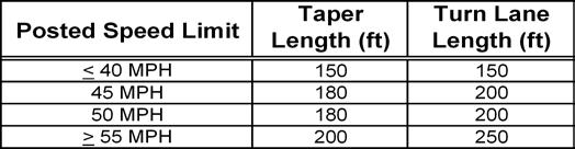
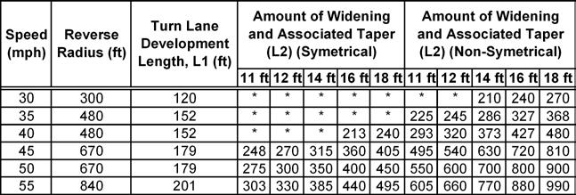
113
114
115 L ft Parallel Face of Curb N curb L 22 (TO 26) ETW 19 ft 17 ft 17 ft 17 ft 17 ft L 0 = ft curb 0 A 16.4 ft N L ft ft 8.5 B = 11 ft 27.4 Maneuvering space ETW L 12 ft 12 ft 12 ft 12 ft 0 = ft curb 0 18 ft A 18.7 ft N L ft B = 14 ft 32.7 Maneuvering space ETW L= given curb length with parking spaces, ft N= number of parking spaces over distance L A= required distance between face of curb and back of stall assuming that bumper of parked car does not extend beyond curb face, ft B= minimum clear distance needed for a parked vehicle to back out of stall while clearing adjacent parked vehicle, ft ETW= Edge of Traveled Way * See SCHDM Figures 21.3A and 21.3C for parking lane widths ON-STREET PARKING CONFIGURATIONS FIGURE A-11 South Carolina Department of Transportation Access and Roadside Management Standards
116 ACCESS AND ROADSIDE MANAGEMENT STANDARDS B-1 Appendix B SCDOT Personnel Contact Information HEADQUARTERS: South Carolina Department of Transportation 955 Park Street Post Office Box 191 Columbia, South Carolina The following officials are located in the headquarters building: Deputy Director for Construction, Engineering, and Planning...(803) Director of Traffic Engineering...(803) Director of Maintenance...(803) Director of Construction...(803) Director of Preconstruction...(803) Utilities Engineer...(803) DISTRICT ENGINEERING ADMINISTRATORS AND OTHER DISTRICT PERSONNEL: District One District Two District Three District Four 1400 Shop Road Columbia, SC W. Alexander Avenue Greenwood, SC South Pleasantburg Drive Greenville, SC J. A. Cochran Bypass Post Office Box 130 Chester, SC District Five Post Office Box 1911 Florence, SC District Six District Seven 6355 Fain Blvd. North Charleston, SC US Route 178 East Bowman Road Drawer 1086 Orangeburg, SC (803) (864) (864) (803) (843) (843) (803) B EDITION
117 ACCESS AND ROADSIDE MANAGEMENT STANDARDS B-2 RESIDENT MAINTENANCE ENGINEERS: County Street Address City, State, Zip Telephone 01 Abbeville 127 McGowan Avenue Abbeville, SC (864) Aiken P. O. Box 2010 Aiken, SC (803) Allendale P. O. Box 296 Allendale, SC (803) Anderson 4740 Liberty Highway Anderson, SC (864) Bamberg P. O. Box 545 Bamberg, SC (803) Barnwell P. O. Box 366 Barnwell, SC (803) Beaufort 13 Munch Drive Beaufort, SC (843) Berkeley P. O. Box 698 Moncks Corner, SC (843) Calhoun P. O. Box 406 St. Matthews, SC (803) Charleston 6355-C Fain Blvd. N. Charleston, SC (843) Cherokee P. O. Box 237 Gaffney, SC (864) Chester P. O. Box 386 Chester, SC (803) Chesterfield P. O. Box 649 Chesterfield, SC (843) Clarendon P. O. Box 26 Manning, SC (803) Colleton P. O. Box 169 Walterboro, SC (843) Darlington P. O. Drawer 495 Darlington, SC (843) Dillon P. O. Box 1009 Dillon, SC (843) Dorchester P. O. Box 96 St. George, SC (843) Edgefield P. O. Box 490 Edgefield, SC (803) Fairfield P. O. Box 261 Winnsboro, SC (803) Florence P. O. Box 1911 Florence, SC (843) Georgetown P. O. Box 593 Georgetown, SC (843) Greenville 13 Saluda Dam Road Greenville, SC (864) Greenwood 510 W. Alexander Ave. Greenwood, SC (864) Hampton P. O. Box 278 Hampton, SC (803) Horry P. O. Box 1663 Conway, SC (843) Jasper P. O. Box 490 Ridgeland, SC (843) Kershaw P. O. Box 509 Camden, SC (803) Lancaster P. O. Box 929 Lancaster, SC (803) Laurens P. O. Box 750 Laurens, SC (864) Lee P. O. Box 191 Bishopville, SC (803) Lexington P. O. Box 70 Lexington, SC (803) Marion P. O. Box 986 Marion, SC (843) Marlboro P. O. Box 276 Bennettsville, SC (843) McCormick Route 2, Box 83T, Road 53 McCormick, SC (864) Newberry P. O. Drawer 39 Newberry, SC (803) Oconee P. O. Box 38 Richland, SC (864) Orangeburg P. O. Box 508 Orangeburg, SC (803) Pickens P. O. Box 877 Pickens, SC (864) Richland 7201 Fairfield Rd Columbia, SC (803) Saluda P. O. Box 715 Saluda, SC (864) Spartanburg P. O. Box 5706 Spartanburg, SC (864) Sumter P. O. Box 417 Sumter, SC (803) Union P. O. Box 458 Union, SC (864) Williamsburg PO Box 180 Kingstree, SC (843) York P. O. Box 2932 CRS Rock Hill, SC (803) B EDITION
118 ACCESS AND ROADSIDE MANAGEMENT STANDARDS B-3 DISTRICT TRAFFIC SIGNAL SUPERVISORS: District 1 (803) District 2 (864) District 3 (864) District 4 (803) District 5 (843) District 6 (843) District 7 (803) Headquarters (803) B EDITION

119 ACCESS AND ROADSIDE MANAGEMENT STANDARDS B-4 B EDITION
120 ACCESS AND ROADSIDE MANAGEMENT STANDARDS C-1 Appendix C Directions for Completion of Permit Application Note: Reference the following eight guidelines to the sample permit applications on pages B-2 through B-3. See pages B-4 and B-5 for a checklist and sample sketches. 1) A permit number will be assigned by the Department. 2) Fill in name and address of applicant (owner or his or her agent). Provide telephone number(s) at which the contact person may be reached 24 hours a day, 7 days a week. Give name of contact person if different from applicant 3) Provide name of county, road or route number, and road name if known. 4) Provide a detailed description of the type of encroachment (driveway, landscape, subdivision street, etc.). 5) Provide description of location. For example, 2.1 miles north of intersection of road S or 300 feet west of road S This information shall also be included on the drawing as instructed in the permit application checklist. 6) Provide applicant s name, signature, and date of application. 7) The Department will provide the date by which the work is to be completed. 8) The Department will add any special provisions to the permit. For example, applicant shall erect Department approved stop signs or work shall only be done between hours of 9 A.M. and 4 P.M. on weekdays. C EDITION
121 ACCESS AND ROADSIDE MANAGEMENT STANDARDS C ,8 Available online at C EDITION
122 ACCESS AND ROADSIDE MANAGEMENT STANDARDS C-3 Encroachment Permit Application Checklist I. Permit Form: The appropriate completed quadruplicate form is required. II. Drawing: At least four copies of a drawing are to be included, giving details of the proposed work and existing conditions and including but not limited to the following: 1) Roadway on which the encroachment is located. 2) Direction and distance to the nearest intersecting State and county roadways, if applicable. 3) North arrow. 4) Drawing to be to scale. For example, 1 = 20 (1:250), 1 = 50 (1:600), etc. 5) Existing and proposed roadway geometry including pavement widths, curves, driveways, etc. 6) Existing and proposed pavement design, if applicable. 7) Existing and proposed drainage features with flow direction. 8) Existing right-of-way and associated property lines. 9) Existing sight distance, if applicable. 10) Existing and proposed structures. 11) Proposed utility work. 12) Traffic Control Plan, if applicable. 13) Erosion control. III. IV. Proof of Bonding: Evidence of any required bond must accompany the permit application. Stormwater Management and Sediment Control Plan: All applications for encroachment permits that involve bringing stormwater water runoff or sediment to the highway for a developed area of 2 acres or more must include a copy of a Stormwater Management and Sediment Control Plan approved by DHEC, the local government, or the conservation district responsible for approving such plans pursuant to The Stormwater Management and Sediment Reduction Act. See S. C. Code Ann. Section , et seq. (Supp. 1995). The plan should include drainage design computations. If the area is less than 2 acres, the application must include a drainage plan with supporting design computations limiting the post construction 10-year peak discharge to the pre-developed 10-year peak. V. Bridges, culverts, retaining walls or other significant structures: All applications for encroachment permit that involve these type of structures must include five signed and sealed copies of the Geotechnical Report, Hydrology Report, Construction Plans and Documents, and Structural Design Calculations as outlined in Chapter 13. C EDITION
123 ACCESS AND ROADSIDE MANAGEMENT STANDARDS C-4 Note: Drawing should be submitted on 8½ x 11 or 11 x 17 size paper. A 36 x 22 site plan showing the relationship of the driveways to the circulation plan and the site development may be required. When readily available, a 36 x 22 site plan should be submitted initially to facilitate review of the application. An example sketch has been provided below. C EDITION
124 SCDOT ACCESS WAIVER This form is a request for approval of waiver from the access guidelines found in SCDOT s Access and Roadside Management Standards. This form shall be accompanied by an Encroachment Permit Application. Submitted By: Date: / / To: Resident Maintenance Engineer PROJECT CHARACTERISTICS County: City: Road/Route: Description of Location: Work Type: Type of Terrain: (Level / Rolling / Mountainous) Posted Speed Limit of Road: (mph) Average Daily Traffic of Road: Driveway Classification: Low Volume Medium Volume High Volume Major Volume 1-20 trips/day trips/day 601-4,000 trips/day >4,000 trips/day 1-5 trips/hour 6-60 trips/hour trips/hour >400 trips/hour Site Land Use: CHECK APPROPRIATE BOX(ES) FOR ACCESS WAIVER(S) Sight Distance Driveway Spacing Corner Clearance Driveway Location Driveway Grade Driveway Width / Radius Driveway Throat Length DESCRIBE ELEMENT(S) FOR ACCESS WAIVER(S) (Attach additional sheets as needed)
125 JUSTIFICATION FOR ACCESS WAIVER(S) (Attach additional sheets as needed) DESCRIBE STEPS TO ELIMINATE ACCESS WAIVER(S), INCLUDE COST (Attach additional sheets as needed) RECORD OF DECISION Resident Maintenance Engineer HQ Section Head/DEA Other Recommended Recommended Recommended Not Recommended Not Recommended Not Recommended JUSTICATION FOR DENIAL OF ACCESS WAIVER (Attach additional sheets as needed) / / / / / / (Resident Maintenance Engineer) (HQ Section Head/DEA) Other cc: Resident Maintenance Engineer (RME) District Traffic Engineer (DTE) District Engineering Administrator (DEA) Director of Traffic Engineering Central File Final Decision Approved Denied

126 ACCESS AND ROADSIDE MANAGEMENT STANDARDS D-1 Appendix D Engineering Directives All SCDOT Engineering Directives are available on the SCDOT internet website at the following web address: D EDITION
127 ACCESS AND ROADSIDE MANAGEMENT STANDARDS D-2 This page intentionally left blank D EDITION
128 ACCESS AND ROADSIDE MANAGEMENT STANDARDS E-1 Appendix E Frequently Asked Questions for Landscaping Irrigation and Maintenance As SCDOT moves forward to enhance SC highways, we have considered the need for irrigation and long-term maintenance. In this regard, our State Highway Engineer is requiring that all landscaping projects on the Department's R/W with extensive landscaping have provisions for maintenance including irrigation systems. We encourage the use of irrigation systems that will reduce hand watering of landscaping on our R/W. Applicants for encroachment permits should refer to the requirements in Section 4E-2 in the Access & Roadside Standards handbook. 1. What determines an extensive landscape project, the size of the project or the dollars spent on the project? Both--SCDOT determines this on a case-by-case basis. When it is practical and cost effective to install an irrigation system, the system should be incorporated into your project. The cost of the irrigation system can be included in the itemized list of the Project Cost. If the cost of the irrigation system exceeds the cost of the total landscaping, then it may be more cost effective to hand water the landscaping. Irrigation Recommendations for Sample Enhancement Projects A. My streetscape enhancement project (on DOT R/W) includes some street tree planting, but a majority of the cost of the project involves new sidewalks, light poles and other street furniture. Do I need to include a sprinkler irrigation system? A sprinkler irrigation system (or a drip system) is recommended. If the landscaping is not spread out over several blocks, the irrigation system would probably be costeffective during the sidewalk construction. If an irrigation system is not included, then you will need to stipulate some type alternative watering of the landscaping. These alternatives include watering by city crews on a regular basis or using "gatorbags" to assist in long-term watering operations. B. My bikeway/landscaping or recreational path/landscaping enhancement project involves street tree planting, but it is spread over a length of several miles. Do I need to include a sprinkler irrigation system? A sprinkler irrigation system (or a drip system) probably would not be cost effective over that distance. If an irrigation system is not included, then you will need to stipulate some type alternative watering of the landscaping. These alternatives include watering by city crews on a regular basis or using "gatorbags" to assist in long-term watering operations. C. My railroad depot restoration project contains a substantial amount of landscaping on the grounds. Do I need to include a sprinkler irrigation system? Yes. A location such as this would already have a water hook up and there would be no need for a well to supply water. 2. My enhancement project is not on SCDOT right-of-way. Am I still required to include arrangements for irrigation for extensive landscaping in my project? Yes, in order for us to ensure that the landscaping will be watered. 3. What will the SCDOT require if the area is in a location where there is no water hook up/connection? In this type of situation, a well can be dug, and the cost can be included in the itemized list of the Project Cost. For example, Adopt-An-Interchange projects often involve extensive landscaping in a concentrated area, and therefore sprinkler irrigation systems are strongly recommended. E EDITION

129 ACCESS AND ROADSIDE MANAGEMENT STANDARDS E-2 4. Will the SCDOT allow us to include the cost of water and the long-term cost of the maintenance of the sprinkler irrigation system in the expenses in our cost estimate? No, the SCDOT can only provide funds for initial installation costs. Any type of long-term maintenance, including landscape maintenance, should not be included in the itemized list of the Project Cost. Additional guidance on landscaping can be found on the SCDOT website at E EDITION
Access Location, Spacing, Turn Lanes, and Medians
 Design Manual Chapter 5 - Roadway Design 5L - Access Management 5L-3 Access Location, Spacing, Turn Lanes, and Medians This section addresses access location, spacing, turn lane and median needs, including
Access requests to County streets and roadways are processed through one of the following methods:
 13.1 GENERAL APPLICATION PROCESS Access requests to County streets and roadways are processed through one of the following methods: A. Planned Developments may set general locations for access points.
Driveway Design Criteria
 Design Manual Chapter 5 - Roadway Design 5L - Access Management 5L-4 Driveway Design Criteria A. General For efficient and safe operations, access drives and minor public street intersections can be improved
Recommended Roadway Plan Section 2 - Land Development and Roadway Access
 Recommended Roadway Plan Section 2 - Land Development and Roadway Access SECTION 2 Land Development and Roadway Access 2.1 Land Use and Access Management The Federal Highway Administration (FHWA) defines
Access Management Standards
 Access Management Standards Section 1: Application of Access Standards This chapter describes the Department's access management standards for access connections on the county roadway system. The standards
INDEX. Geometric Design Guide for Canadian Roads INDEX
 Acceleration lane, see Lanes, Acceleration Access, 8.1 Access Management and Functional Classification 8.2 Access Management by Design Classification 8.3 Access Configuration 8.4 Building Set-Back Guidelines
CHAPTER 1 STANDARD PRACTICES
 CHAPTER 1 STANDARD PRACTICES OBJECTIVES 1) Functions and Limitations 2) Standardization of Application 3) Materials 4) Colors 5) Widths and Patterns of Longitudinal Pavement Marking Lines 6) General Principles
CHAPTER 16 PEDESTRIAN FACILITIES DESIGN AND TECHNICAL CRITERIA TABLE OF CONTENTS
 CHAPTER 16 PEDESTRIAN FACILITIES DESIGN AND TECHNICAL CRITERIA TABLE OF CONTENTS Section Title Page 16.1 General... 16-1 16.1.1 AASHTO Reference... 16-1 16.1.2 ADA Requirements... 16-1 16.2 Sidewalks...
This Chapter sets forth the minimum design, technical criteria and specifications to be used in the preparation of all roadway plans.
 4.1 GENERAL This Chapter sets forth the minimum design, technical criteria and specifications to be used in the preparation of all roadway plans. These Roadway Standards are for new construction and modification
FOR HISTORICAL REFERENCE ONLY
 To: From: Subject: Electronic Distribution Recipients MINNESOTA DEPARTMENT OF TRANSPORTATION Engineering Services Division Technical Memorandum No. 12-14-B-03 December 18, 2012 Jon M. Chiglo, P.E. Division
Appendix T CCMP TRAIL TRAFFIC & TRANSPORTATION DESIGN STANDARD
 Appendix T CCMP 3.3.4 TRAIL TRAFFIC & TRANSPORTATION DESIGN STANDARD 3.3.4 Trail Traffic and Transportation Design Multi-use trails have certain design standards, which vary depending on the agency that
WYDOT DESIGN GUIDES. Guide for. NHS Arterial (Non-Interstate)
") WYDOT DESIGN GUIDES Guide for NHS Arterial (Non-Interstate) 2014 GUIDE FOR NATIONAL HIGHWAY SYSTEM (NHS) HIGHWAYS (NHS ARTERIALS, Non-Interstate) PRESERVATION REHABILITATION RECONSTRUCTION INTRODUCTION
WYDOT DESIGN GUIDES Guide for NHS Arterial (Non-Interstate) 2014 GUIDE FOR NATIONAL HIGHWAY SYSTEM (NHS) HIGHWAYS (NHS ARTERIALS, Non-Interstate) PRESERVATION REHABILITATION RECONSTRUCTION INTRODUCTION
Considerations in the Review and Approval of a Driveway in Your Jurisdiction
 Considerations in the Review and Approval of a Driveway in Your Jurisdiction So, are you the person at your agency who reviews and approves new driveways? Or, perhaps you are part of the TEAM of people
CHAPTER 3A. GENERAL PAGE CHAPTER 3B. PAVEMENT AND CURB MARKINGS PAGE
 Virginia Supplement to the 2009 MUTCD Revision 1 Page TC-3-1 PART 3. MARKINGS CHAPTER 3A. GENERAL PAGE Section 3A.01 Functions and Limitations Section 3A.02 Standardization of Application Section 3A.03
Access Management Regulations and Standards
 Access Management Regulations and Standards Efficient highway operation Reasonable property access Concept of Access Management The way to manage access to land development while simultaneously preserving
WYDOT DESIGN GUIDES. Guide for. Non-NHS State Highways
 WYDOT DESIGN GUIDES Guide for Non-NHS State Highways 2014 GUIDE FOR Non-NATIONAL HIGHWAY SYSTEM (Non-NHS) STATE HIGHWAYS PRESERVATION REHABILITATION RECONSTRUCTION INTRODUCTION This Guide is directed to
Roadway Design Manual
 Roadway Design Manual Manual Notice Archive by Texas Department of Transportation (512) 302-2453 all rights reserved Manual Notice 2009-1 From: Manual: Mark A. Marek, P.E Roadway Design Manual Effective
Chapter 2: Standards for Access, Non-Motorized, and Transit
 Standards for Access, Non-Motorized, and Transit Chapter 2: Standards for Access, Non-Motorized, and Transit The Washtenaw County Access Management Plan was developed based on the analysis of existing
Roadway Design Manual
 Roadway Design Manual Revised December 2013 2013 by Texas Department of Transportation (512) 302-2453 all rights reserved Manual Notice 2013-1 From: Manual: Mark A. Marek, P.E Roadway Design Manual Effective
Geometric Design Tables
 Design Manual Chapter 5 - Roadway Design 5C - Geometric Design Criteria 5C-1 Geometric Design Tables A. General The following sections present two sets of design criteria tables - Preferred Roadway Elements
Roadway Classification Design Standards and Policies. Pueblo, Colorado November, 2004
 Roadway Classification Design Standards and Policies Pueblo, Colorado November, 2004 Table of Contents Page Chapter 1. General Provisions 1.1 Jurisdiction 3 1.2 Purpose and Intent 3 1.3 Modification 3
General Design Factors
 Chapter 3: 3-1.0 Introduction General Design Factors Mn/DOT s goals include encouraging and accommodating safe bicycling. From a design perspective, these goals are achieved by first having an understanding
Access Management Regulations and Standards for Minor Arterials, Collectors, Local Streets
 Access Management Regulations and Standards for Minor Arterials, Collectors, Local Streets September 2009 Paul Grasewicz Access Management Administrator Concept of Access Management The way to manage access
Figure 3B-1. Examples of Two-Lane, Two-Way Marking Applications
 Figure 3B-1. Examples of Two-Lane, Two-Way Marking Applications A - Typical two-lane, two-way marking with passing permitted in both directions B - Typical two-lane, two-way marking with no-passing zones
MUTCD Part 6G: Type of Temporary Traffic Control Zone Activities
 MUTCD Part 6G: Type of Temporary Traffic Control Zone Activities 6G.01 Typical Applications Each temporary traffic control (TTC) zone is different. Many variables, such as location of work, highway type,
MUTCD Part 6: Temporary Traffic Control
 MUTCD Part 6: Temporary Traffic Control OMUTCD English units are preferred. OHIO MANUAL OF UNIFORM TRAFFIC CONTROL DEVICES TABLE OF CONTENTS PREFACE INTRODUCTION TABLE OF CONTENTS PART 1. GENERAL Chapter
THE FUTURE OF THE TxDOT ROADWAY DESIGN MANUAL
 THE FUTURE OF THE TXDOT ROADWAY DESIGN MANUAL Kenneth Mora, P.E. (Design Division) 10/10/2017 Table of contents 1 2 Reduction in FHWA design controlling criteria Innovative Intersection Guidance 3-7 8-42
ROUNDABOUTS/TRAFFIC CIRCLES
 GENERAL 1. Description This standard identifies minimum requirements that shall be met for Roundabouts and Neighborhood Traffic Circles in the design and construction of elements for Arlington County Horizontal
Access Management in the Vicinity of Intersections
 Access Management in the Vicinity of Intersections FHWA-SA-10-002 Technical Summary Photo: Ralph Bentley (used with permission) 0 Access Management is: The design, implementation and management of entry
October 2004 REVISIONS (2) SUPERELEVATION DEVELOPMENT 11.3(2)
 SUPERELEVATION DEVELOPMENT 11.3(2)") October 2004 REVISIONS (2) Chapter 11 HORIZONTAL ALIGNMENT SUPERELEVATION DEVELOPMENT 11.3(2) Chapter 12 VERTICAL ALIGNMENT VERTICAL CURVES PASSING SIGHT DISTANCE 12.5(2) VERTICAL CURVES STOPPING SIGHT
October 2004 REVISIONS (2) Chapter 11 HORIZONTAL ALIGNMENT SUPERELEVATION DEVELOPMENT 11.3(2) Chapter 12 VERTICAL ALIGNMENT VERTICAL CURVES PASSING SIGHT DISTANCE 12.5(2) VERTICAL CURVES STOPPING SIGHT
Section 3A.04 Colors. Section 3B.10 Approach Markings for Obstructions
 Section 3A.04 Colors Markings shall be yellow, white, red, or blue, or purple. The colors for markings shall conform to the standard highway colors. Black in conjunction with one of the above colors shall
Access Management Guidelines February 2013 THE CITY OF
 Access Management Guidelines February 2013 THE CITY OF Table of Contents Introduction 2 Review and Approval Process 5 Technical Guidelines 9... 10... 12 3. Separation Distance: Non-Signalized All-Turns
SECTION 3 STREET DESIGN
 3.01 GENERAL SECTION 3 STREET DESIGN For purposes of geometric and structural design, streets shall be classified according to the following table. The City Engineer will determine the class of all proposed
(This page left intentionally blank)
") (This page left intentionally blank) 2011 Edition - Revision 1 Page 553 Section 5A.01 Function CHAPTER 5A. GENERAL 01 A low-volume road shall be defined for this Part of the Manual as follows: A. A low-volume
(This page left intentionally blank) 2011 Edition - Revision 1 Page 553 Section 5A.01 Function CHAPTER 5A. GENERAL 01 A low-volume road shall be defined for this Part of the Manual as follows: A. A low-volume
PennDOT Access Management Model Ordinances Training
 PennDOT Access s Training Trainers: Chad Dixson, AICP, TPD Angela Watson, PB Objective of Today Assist Pennsylvania s municipalities and transportation professionals in better understanding the benefits
M-58 HIGHWAY ACCESS MANAGEMENT STUDY Mullen Road to Bel-Ray Boulevard. Prepared for CITY OF BELTON. May 2016
 M-58 HIGHWAY ACCESS MANAGEMENT STUDY Prepared for CITY OF BELTON By May 2016 Introduction Missouri State Highway 58 (M-58 Highway) is a major commercial corridor in the City of Belton. As development has
MUNICIPALITY OF ANCHORAGE Traffic Department MEMORANDUM
 MUNICIPALITY OF ANCHORAGE DATE: MEMORANDUM TO: FROM: SUBJECT: Anchorage Contractors, Builders, Designers, and Land Owners Robert E. Kniefel, P.E., Municipal Traffic Engineer Municipal Driveway Standards
Central Arkansas Regional Transportation Study Area ROADWAY DESIGN STANDARDS And Implementation Procedures
 Central Arkansas Regional Transportation Study Area ROADWAY DESIGN STANDARDS And Implementation Procedures These standards have been prepared for the use of all jurisdictions to incorporate into their
Street Paving and Sidewalk Policy
 City Commission Policy 600 Street Paving and Sidewalk Policy DEPARTMENT: Public Works DATE ADOPTED: June 7, 1995 DATE OF LAST REVISION: December 10, 2014 Policy No. 600.01 AUTHORITY: PASS City of Tallahassee-Leon
Access Management Regulations and Standards
 Access Management Regulations and Standards January 2014 Efficient highway operation Reasonable property access Concept of Access Management The way to manage access to land development while preserving
Alberta Infrastructure HIGHWAY GEOMETRIC DESIGN GUIDE AUGUST 1999
 Alberta Infrastructure HIGHWAY GEOMETRIC DESIGN GUIDE AUGUST 1999,1'(; A ACCELERATION Data on acceleration from stop D-29 Effects of grade D-35 Intersections D-97, D-99 Lanes D-97, F-5, F-7, F-15, F-21,
REGIONAL BICYCLE AND PEDESTRIAN DESIGN GUIDELINES
 REGIONAL BICYCLE AND PEDESTRIAN DESIGN GUIDELINES November 16, 2011 Deb Humphreys North Central Texas Council of Governments Bicycle and Pedestrian Advisory Committee Snapshot of the Guide 1. Introduction
PLACEMENT OF SIGNS RECOMMENDED PRACTICES SUB-SECTION
 Page 1 of 6 RECOMMENDED PRACTICES PART SECTION SUB-SECTION HIGHWAY SIGNS GENERAL General Proper positioning of signs is an important element in the overall control of traffic within a roadway network.
INTERSECTIONS AT GRADE INTERSECTIONS
 INTERSECTIONS 1 AT GRADE INTERSECTIONS INTERSECTIONS INTERSECTIONS = INTERRUPTED FACILITIES Definitions and key elements An intersection is defined as an area where two or more roadways join or cross.
Developed by: The American Traffic Safety Services Association (ATSSA) 15 Riverside Parkway, Suite 100 Fredericksburg, VA
 15 Riverside Parkway, Suite 100 Fredericksburg, VA") Addendum Developed by: The American Traffic Safety Services Association (ATSSA) 15 Riverside Parkway, Suite 100 Fredericksburg, VA 22406-1022 800-272-8772 This material is based upon work supported by
Addendum Developed by: The American Traffic Safety Services Association (ATSSA) 15 Riverside Parkway, Suite 100 Fredericksburg, VA 22406-1022 800-272-8772 This material is based upon work supported by
1 VicRoads Access Management Policies May 2006 Ver VicRoads Access Management Policies May 2006 Version 1.02
 1 VicRoads Access Management Policies May 2006 Ver 1.02 VicRoads Access Management Policies May 2006 Version 1.02 2 VicRoads Access Management Policies May 2006 Ver 1.02 FOREWORD FOR ACCESS MANAGEMENT
County of Greenville South Carolina. Traffic Calming Program Neighborhood Traffic Education Program and Speed Hump Program
 County of Greenville South Carolina Traffic Calming Program Neighborhood Traffic Education Program and Speed Hump Program (rev) August 2008 I. PURPOSE The potential negative impacts from vehicular traffic
Appendix C. TRAFFIC CALMING PROGRAM TOOLBOX
 Appendix C. TRAFFIC CALMING PROGRAM TOOLBOX PHASE I...2 Do Not Enter Sign...3 One-Way Sign...4 Turn Prohibition...5 Pavement Markings...6 Speed Monitoring Trailer...7 Neighborhood Speed Watch...8 Police
Active Transportation Facility Glossary
 Active Transportation Facility Glossary This document defines different active transportation facilities and suggests appropriate corridor types. Click on a facility type to jump to its definition. Bike
Attachment No. 13. National Committee on Uniform Traffic Control Devices RWSTC RECOMMENDATION FOLLOWING SPONSOR COMMENTS
 1 2 3 4 Attachment No. 13 5 6 7 8 9 10 11 12 13 14 15 16 17 18 19 20 21 22 23 24 25 26 27 28 29 30 31 32 33 34 35 36 37 38 39 40 41 42 43 RWSTC agenda item IV. 2 June 2011 National Committee on Uniform
City of Albert Lea Policy and Procedure Manual 4.10 ALBERT LEA CROSSWALK POLICY
 4.10 ALBERT LEA CROSSWALK POLICY PURPOSE: Pedestrian crosswalks are an integral part of our transportation infrastructure. To be effective and promote safety, marked crosswalks must be installed after
5. RUNNINGWAY GUIDELINES
 5. RUNNINGWAY GUIDELINES These guidelines should be considered collectively when making runningway decisions. A runningway is the linear component of the transit system that forms the right-of-way reserved
Off-road Trails. Guidance
 Off-road Trails Off-road trails are shared use paths located on an independent alignment that provide two-way travel for people walking, bicycling, and other non-motorized users. Trails specifically along
TRAFFIC STUDY GUIDELINES Clarksville Street Department
 TRAFFIC STUDY GUIDELINES Clarksville Street Department 9/1/2009 Introduction Traffic studies are used to help the city determine potential impacts to the operation of the surrounding roadway network. Two
Grade Separated Intersection
 Grade Separated Intersection Lecture Notes in Transportation Systems Engineering Prof. Tom V. Mathew Contents 1 Overview 1 2 Classification of Intersection 2 2.1 Grade Separated Intersection...........................
Median Design. Course No: C Credit: 4 PDH. Debra Kennaugh, P.E.
 Median Design Course No: C04-041 Credit: 4 PDH Debra Kennaugh, P.E. Continuing Education and Development, Inc. 9 Greyridge Farm Court Stony Point, NY 10980 P: (877) 322-5800 F: (877) 322-4774 info@cedengineering.com
CHAPTER 2G. PREFERENTIAL AND MANAGED LANE SIGNS
 2011 Edition - Revision 2 Page 275 Section 2G.01 Scope CHAPTER 2G. PREFERENTIAL AND MANAGED LANE SIGNS 01 Preferential lanes are lanes designated for special traffic uses such as high-occupancy vehicles
700 Multi-Modal Considerations
 700 Multi-Modal Considerations Table of Contents 701 Railroads... 7-1 701.1 Background... 7-1 701.2 Crossing At-Grade... 7-1 701.2.1 General... 7-1 701.2.2 Railroad Parallel to Highway... 7-1 701.3 Lateral
Traffic Engineering and Highway Safety Bulletin June Overview
 Traffic Engineering and Highway Safety Bulletin 18-03 June 2018 INTERSECTION GEOMETRIC DESIGN In This Issue Overview... 1 Intersection Types... 2 Traffic Control Selection... 3 Capacity Analysis... 6 Design
Roads that are intended to be included in the VDOT system of maintained roadways must meet the standards and specifications prescribed by the VDOT.
 SECTION 1 - GENERAL 1-1 Purpose This Manual has been prepared to promote uniform design procedures for designers and technicians in the development of property and roads in the County of Henrico, Virginia.
Town of Mooresville, North Carolina Neighborhood Traffic Calming and Control Device Policy
 Town of Mooresville, North Carolina Neighborhood Traffic Calming and Control Device Policy Adopted January 6, 2014 Town of Mooresville Development Services Department TOWN OF MOORESVILLE NEIGHBORHOOD TRAFFIC
Appendix 3 Roadway and Bike/Ped Design Standards
 Appendix 3 Roadway and Bike/Ped Design Standards OTO Transportation Plan 2040 4/20/2017 Page A3-1 Adopted Standards The adopted OTO Design Standards and Major Thoroughfare Plan are contained herein.
American Railway Engineering and Maintenance of Way Association Letter Ballot. Draft
 American Railway Engineering and Maintenance of Way Association Letter Ballot 1. Committee and Subcommittee: Committee 5 Track Subcommittee 9 Road Crossings 2. Letter Ballot Number: 05-17-16 3. Assignment:
City of Vallejo Traffic Calming Toolbox
 City of Vallejo Traffic Calming Toolbox June 1, 2013 Final Table of Contents Introduction... 1 Non-Physical Devices... 3 High-Visibility Crosswalk... 3 In Pavement Lighted Crosswalk... 4 Rapid Flashing
Designing for Pedestrian Safety. Alabama Department of Transportation Pre-Construction Conference May 2016
 Designing for Pedestrian Safety Alabama Department of Transportation Pre-Construction Conference May 2016 1 Designing for Pedestrians Marking Crosswalks at Signalized intersections High Visibility Markings
TOWN OF CHAPEL HILL POLICY AND PROCEDURES FOR TRAFFIC CALMING MEASURES
 TOWN OF CHAPEL HILL POLICY AND PROCEDURES FOR TRAFFIC CALMING MEASURES (Adopted by the Town Council on June 30, 2004) (Revised December 6, 2010) (Revised February 8, 2016) POLICY AND PROCEDURES FOR TRAFFIC
3.1 TRAFFIC CALMING PROCESS SUMMARY
 SECTION 3 3.0 TRAFFIC CALMING 3.1 TRAFFIC CALMING PROCESS SUMMARY Traffic calming is a means in which to reduce speeds and minimize vehicular traffic on local neighborhood streets. Citizen involvement
1.3.4 CHARACTERISTICS OF CLASSIFICATIONS
 Geometric Design Guide for Canadian Roads 1.3.4 CHARACTERISTICS OF CLASSIFICATIONS The principal characteristics of each of the six groups of road classifications are described by the following figure
Traffic Calming Policy
 Article I. Purpose and Goal. The purpose of this policy is to establish criteria and procedures the City will use to evaluate requests for, and if appropriate, implement traffic calming measures. Neighborhood
SECTION 1 - TRAFFIC PLANNING
 SECTION 1 - TRAFFIC PLANNING 1.1 TRAFFIC OPERATIONS 1.1.1 Roadway Functional Classification The Multnomah County Comprehensive Framework Plan s Policy 34: Trafficways and the Functional Classification
American Fork City Access Management Manual
 American Fork City Access Management Manual American Fork, Utah April 2012 UT09-181 3315 West Mayflower Way, Ste. 4 Lehi, Utah 84043 p. 801/ 766.4343 www.halesengineering.com EXECUTIVE SUMMARY As traffic
Access Management Design Standards for Entrances and Intersections
 Access Management Design Standards for Entrances and Intersections July 2012 APPENDIX F VDOT Road Design Manual PREFACE The access management regulations and standards do not apply in cities, towns of
Classification Criteria
 SCHEDULE D TO RECOMMENDED OFFICIAL PLAN AMENDMENT NO. 40 SCHEDULE C-4 Road Criteria Criteria Traffic Service Objective Land Service/Access Typical Daily Traffic Volume Flow characteristics Travel Speed
DEFINITIONS Activity Area - Advance Warning Area Advance Warning Sign Spacing Advisory Speed Approach Sight Distance Attended Work Space
 DEFINITIONS Activity Area - that part of a TTC zone activity area where the work actually takes place. It consists of the work space, traffic space and one or more buffer spaces. Advance Warning Area -
MEMORANDUM. Date: 9/13/2016. Citywide Crosswalk Policy
 MEMORANDUM Date: 9/13/2016 Re: Citywide Crosswalk Policy Foreword Through the s Circulation Element and Complete Streets Policy, it is the City s goal to promote walking trips and provide safe facilities
77th OREGON LEGISLATIVE ASSEMBLY Regular Session. House Bill 2732 SUMMARY
 Sponsored by Representative BUCKLEY th OREGON LEGISLATIVE ASSEMBLY--0 Regular Session House Bill SUMMARY The following summary is not prepared by the sponsors of the measure and is not a part of the body
Chapter 4 On-Road Bikeways
 Chapter 4: 4-1.0 Introduction On-Road Bikeways This chapter provides guidelines to help select and design safe on-road bikeways. On-road bikeways include bicycle lanes, shared lanes, shoulders, and wide
TRAFFIC LINE MANUAL Edition Revision 1 June 2012 TRAFFIC-ROADWAY SECTION
 TRAFFIC LINE MANUAL 2011 Edition Revision 1 June 2012 TRAFFIC-ROADWAY SECTION TABLE OF CONTENTS Foreword...iv Section A: General Principles A-1 Functions and Limitations... 1 A-2 Colors... 1 A-3 Colored
BDC07MR-05. Section 6
 BDC07MR-05 Section 6 6.1 General Most highways intersect at grade. To minimize the resulting conflicts and to provide adequately for the anticipated crossings and turning movements, the geometric design
TRAFFIC CALMING GUIDE FOR TORONTO CITY OF TORONTO TRANSPORTATION SERVICES DIVISION
 TRAFFIC CALMING GUIDE FOR TORONTO CITY OF TORONTO TRANSPORTATION SERVICES DIVISION CITY OF TORONTO TRANSPORTATION SERVICES DIVISION 2016 TRAFFIC CALMING GUIDE FOR TORONTO TABLE OF CONTENTS Introduction
APPENDIX B Boonville Code of Ordinances. BOONVILLE, MISSOURI Access Management Manual. March Revised April 2009 INDEX
 APPENDIX B Boonville Code of Ordinances BOONVILLE, MISSOURI Access Management Manual March 2002 Revised April 2009 INDEX Section Page 1.0 Introduction and Definitions. 2 2.0 Roadway Classification System.
Table of Contents. Introduction. Prompt List Arterials and Streets. Prompt List Interchange. Prompt List Intersections. Prompt List Limited Access
 Table of Contents Introduction Prompt List Arterials and Streets Prompt List Interchange Prompt List Intersections Prompt List Limited Access Prompt List MOT Prompt List Pedestrian Bicyclist Prompt List
Chapter 3 - Local Urban Road System CHAPTER 3 LOCAL URBAN ROAD SYSTEM
 CHAPTER 3 LOCAL URBAN ROAD SYSTEM 3.0 INTRODUCTION As in Chapter 2 for the local rural road system, the local urban road system also utilizes the concepts of land use context, functional classification
PART 5. TRAFFIC CONTROL DEVICES FOR LOW-VOLUME ROADS TABLE OF CONTENTS
 2005 Edition Page TC5-1 PART 5. TRAFFIC CONTROL DEVICES FOR LOW-VOLUME ROADS TABLE OF CONTENTS CHAPTER 5A. Section 5A.01 Section 5A.02 Section 5A.03 Section 5A.04 CHAPTER 5B. GENERAL Page Function...5A-1
FORT WAYNE - NEW HAVEN - ALLEN COUNTY ACCESS STANDARDS MANUAL. Introduction and Objectives... I. Access Management Elements... 1
 FORT WAYNE - NEW HAVEN - ALLEN COUNTY ACCESS STANDARDS MANUAL Introduction and Objectives............................................ PAGE i I. Access Management Elements.....................................
Chapter Twenty-eight SIGHT DISTANCE BUREAU OF LOCAL ROADS AND STREETS MANUAL
 Chapter Twenty-eight SIGHT DISTANCE BUREAU OF LOCAL ROADS AND STREETS MANUAL Jan 2006 SIGHT DISTANCE 28(i) Chapter Twenty-eight SIGHT DISTANCE Table of Contents Section Page 28-1 STOPPING SIGHT DISTANCE
TRAFFIC CONTROL DEVICES FOR LOW VOLUME ROADS
 PART 5. TRAFFIC CONTROL DEVICES FOR LOW VOLUME ROADS TABLE OF CONTENTS Chapter 5A. GENERAL Page Section 5A.1 Function............................................................... 5A-1 5A.2 Application............................................................
Section 9A.07 Meaning of Standard, Guidance, Option, and Support
 2012 Edition Page 895 PART 9. TRAFFIC CONTROLS FOR BICYCLE FACILITIES CHAPTER 9A. GENERAL Section 9A.01 Requirements for Bicyclist Traffic Control Devices 01 General information and definitions concerning
CHAPTER 6H. TYPICAL APPLICATIONS
 2006 Edition Page 6H-1 CHAPTER 6H. TYPICAL APPLICATIONS Section 6H.01 Typical Applications Support: Whenever the acronym TTC is used in this Chapter, it refers to temporary traffic control. Standard: The
APPENDIX F. Access Management Design Standards for Entrances and Intersections
 APPENDIX F Access Management Design Standards for Entrances and Intersections PREFACE The access management regulations and standards do not apply in cities, towns of more than 3,500 and in counties (Henrico
Chapter 33. Grade Separated Intersection Overview Classification of Intersection Grade Separated Intersection
 Chapter 33 Grade Separated Intersection 33.1 Overview An intersection is the area shared by the joining or crossing of two or more roads. Since the main function of an intersection is to enable the road
TEMPORARY TRAFFIC CONTROL GUIDELINES FOR HIGHWAY-RAIL GRADE CROSSINGS
 TEMPORARY TRAFFIC CONTROL GUIDELINES FOR HIGHWAY-RAIL GRADE CROSSINGS 1.0 INTRODUCTION 1.1 Purpose The Southern California Regional Rail Authority (SCRRA) is the designated track owner of the Metrolink
Document 2 - City of Ottawa Pedestrian Crossover (PXO) Program
 Program") 40 Document 2 - City of Ottawa Pedestrian Crossover (PXO) Program OVERVIEW The City of Ottawa Pedestrian Crossover (PXO) Program provides the basis for PXO implementation in Ottawa. The program s processes
40 Document 2 - City of Ottawa Pedestrian Crossover (PXO) Program OVERVIEW The City of Ottawa Pedestrian Crossover (PXO) Program provides the basis for PXO implementation in Ottawa. The program s processes
Oregon Supplement to the Manual on Uniform Traffic Control Devices. Adopted July 2005 by OAR
 Oregon Supplement to the Manual on Uniform Traffic Control Devices Adopted July 2005 by OAR 734-020-0005 2003 Edition Oregon Supplement to the MUTCD Page 2 INTRODUCTION Traffic control devices installed
Railroad Inspection Procedure Manual
 Railroad Inspection Procedure Manual Railroad Inspection Procedure Manual Table of Contents Introduction... 1 Inspection Report t For orm... 3 Instructions for Completing Inspection Report t For orms...
What Is a Complete Street?
 Session 5 Charleen Zimmer, AICP, Zan Associates May 5-7, 2010 What Is a Complete Street? May 2010 5-1 Not a Complete Street More of a Complete Street May 2010 5-2 Benefits of Complete Streets Safety for
City of Roseville Section 13 Design Standards. _Bikeways January 2016 SECTION 13 BIKEWAYS
 SECTION 13 BIKEWAYS 13-1 GENERAL The City of Roseville bikeway standards are designed to insure that transportation and recreational bikeways are constructed in a manner that would provide a safe and comfortable
APPENDIX A: Complete Streets Checklist DRAFT NOVEMBER 2016
 APPENDIX A: Complete Streets Checklist DRAFT NOVEMBER 2016 Complete Streets Checklist MetroPlan Orlando s Complete Streets Checklist is an internal planning tool for staff to further implementation of
Design Criteria. Design Criteria
 F Design Criteria Design Criteria Ministry of Transportation Ministère des Transports DESIGN CRITERIA Page: 1 of 13 WORK PROJECT NO. N/A GO Bloomington Station TYPE OF PROJECT LOCATION Bloomington Road
(This page left intentionally blank)
") (This page left intentionally blank) 2011 Edition- Revision 2 Page 813 CHAPTER 9A. GENERAL Section 9A.01 Requirements for Bicyclist Traffic Control Devices 01 General information and definitions concerning
(This page left intentionally blank) 2011 Edition- Revision 2 Page 813 CHAPTER 9A. GENERAL Section 9A.01 Requirements for Bicyclist Traffic Control Devices 01 General information and definitions concerning