PART 1 - Assembly...2
|
|
|
- Mariah Skinner
- 6 years ago
- Views:
Transcription


1


2 PART 1 - Assembly...2 Parts List and Parts Descriptions Assembly Steps Positioning & Adjusting for comfort...8 Recording Order Information...8 PART 2 Using the Vasa Kayak Ergometer...9 Safety Review Resistance Settings Using the Vasa Power Meter Power Meter - Summary of Functions Training Log Training Notes PART 3 - Maintenance & Troubleshooting...30 Maintenance Instructions Troubleshooting Guarantee & Warranty Information VASA, INC. 1 ALLEN MARTIN DRIVE ESSEX JUNCTION, VERMONT USA TEL: FAX: info@vasatrainer.com WEB:
 VE-K-PS-KIT K1 Racing Seat (1) VE-K1SEAT Monorail (1) 16-AL Foot Brace (1) VE-K-FB ***OPTIONAL*** Power Meter (1)")
 VE-1-WB-3 Goose Neck (1) VE-K3 SAVE ALL PACKAGING Boxes & inner packaging Vasa Kayak Ergometer")
3 PART 1 - ASSEMBLY 1.1 PART IDENTIFICATION Please read entire assembly section before beginning assembly. Kayak Paddle Shaft (1) VE-K-PS-KIT K1 Racing Seat (1) VE-K1SEAT Monorail (1) 16-AL Foot Brace (1) VE-K-FB ***OPTIONAL*** Power Meter (1) VM-1 / VM-1-ANT+ PM Mounting Bracket (1) VE-1-MMB-KIT Rear Low Stanchion (1) VE-K2 Front End Assembly (1) ERGO-FE 2012 FRONT END ASSEMBLY OPPOSITE VIEW Wheel Bracket Assembly (1) VE-1-WB-3 Goose Neck (1) VE-K3 SAVE ALL PACKAGING Boxes & inner packaging Vasa Kayak Ergometer User s Manual PART 1 - Assembly 3
4 1.2 PARTS LIST The parts for your Vasa Kayak Ergometer are packed in three boxes. Please unpack and assemble your new Vasa Kayak Ergometer in the specific order outlined on the following pages. IMPORTANT: Please save the large front end assembly box and its inner packaging. That packaging is specifically designed to protect the front assembly. In the unlikely event that you would need to ship the Vasa Kayak Ergometer, we recommend using that packaging for the front assembly. PART NAME PART # QUANTITY REAR LOW STANCHION VE-K2 1 K1 RACING SEAT ASSEMBLY K1 SEAT KIT 1 Button Head Pilot Screw-SS 14P-PILOT 8 Thin Nylon Insert Nut-SS 18PS 8 Knob for Kayak Bracket Lock Bolt VE-K-KNOB 2 Kayak Bracket Lock Bolt VE-K-LB 2 K1 Seat Side Plate VE-KS-2 2 K1 Seat Mounting Bracket VE-KS-3 1 K1 Kayak Molded Seat VE-K1SEAT 1 MONORAIL 16-AL-E 1 KAYAK PADDLE SHAFT VE-K-PS-KIT 1 (2 sections) KAYAK FOOT BRACE ASSEMBLY VE-K-FB-KIT 1 K1 Foot Brace VE-K-FB-6 1 Kayak Foot Brace Slippery Tape VE-K-FB-TAPE 1 Kayak Lock Bolt Knob VE-K-KNOB 2 Kayak Bracket Lock Bolt VE-K-LB 2 POWER METER (optional) VM-1 or VM-1-ANT+ 1 PM MOUNTING BRACKET ASSEMBLY VE-K-MMB-KIT 1 FRONT ERGOMETER ASSEMBLY ERGO-FE WHEEL BRACKET ASSEMBLY VE-1-WBA 1 INSTRUCTION MANUAL IM-ERGO-K 1 HARDWARE BAG (see below) 1 bag Button Head Screw - 2 1/2 11P 3 Hex Jam Nut 18PS 3 Hex Key Allen Wrench - 3/16 12A-PS 1 Hex Key Allen Wrench - 5/32 12B-PS 1 Wrench - 7/16 14B-PS 1 Wrench - Combo 9/16 & 1/2 14D-PS 1 Screwdriver VE-1-SDR 1 4 Vasa Kayak Ergometer User s Manual PART 1 - Assembly

 into the T-slot on the bottom front of the monorail. VIEW: FRONT/END OF MONORAIL STEP 3.")
5 1.3 ASSEMBLY STEPS STEP 1. INSTALL REAR STANCHION Insert the rear portion of the monorail into the head of the rear stanchion sleeve with T-Slot facing up; Insert the 2.5 bolt through stanchion/monorail holes; Thread hex jam nut onto bolt; Tighten with 5/32 allen wrench and 7/16 wrench; Use 3/16 allen wrench to tighten set screw on stanchion sleeve. VIEW: BACK OF MONORAIL A NOTE: There are two set of holes on one end of the monorail. It does NOT matter which end you insert into the rear stanchion as the second set of holes are not used. C B STEP 2. INSTALL MOUNTING BOLTS Slide the head of the lock bolt (x4) into the T-slot on the bottom front of the monorail. VIEW: FRONT/END OF MONORAIL STEP 3. INSTALL GOOSE NECK ONTO MONORAIL Insert the short end of the goose neck bracket on the front end of the monorail (keep long end above rail as shown); Insert the 2.5 bolt through bracket/monorail holes; Thread hex jam nut onto bolt; Tighten with 5/32 allen wrench and 7/16 wrench; Use 3/16 allen wrench to tighten set screw on bracket. LONG SHORT Vasa Kayak Ergometer User s Manual PART 1 - Assembly 5


6 STEP 4. INSTALL GOOSE NECK ONTO FRONT END Insert the long end of the goose neck bracket into the front end monorail sleeve; Insert the 2.5 bolt through bracket/sleeve holes; Thread hex jam nut onto bolt; Tighten with 5/32 allen wrench and 7/16 wrench; Use 3/16 allen wrench to tighten set screw on bracket. NOTE: Press in the rear cover to allow more clearance for 2 1/2 bolt. INSTALLATION TIP PUSH COVER IN TO INSTALL SCREW STEP 5. INSTALL K1 SEAT Align 2 holes on K1 Seat Plate with 2 Lock Bolts closer to rear stanchion; Install plate onto bolt & thread Locking Knobs (x2) VIEW: BACK PORTION OF MONORAIL STEP 6. INSTALL FOOT BRACE Align 2 holes on the Foot Brace mounting plate with the remaining Lock Bolts; Install plate onto bolt & thread Locking Knobs (x2) VIEW: FRONT PORTION OF MONORAIL 6 Vasa Kayak Ergometer User s Manual PART 1 - Assembly
 into the battery compartment on the back side of the monitor. IMPORTANT: REMOVE THE BATTERIES if the Vasa Ergometer will be idle for 3+ months.")

7 STEP 7: INSTALLING BATTERIES IN THE POWER METER NOTE: Power Meter operation will be covered in Part 2 of this manual. Insert the two AA batteries (included) into the battery compartment on the back side of the monitor. IMPORTANT: REMOVE THE BATTERIES if the Vasa Ergometer will be idle for 3+ months. CAUTION: The Power Meter is a sensitive unit. Please handle with care at all times. STEP 10. INSTALL MONITOR MOUNTING BRACKET Attach the Velcro strap with the monitor mounting bracket to the front end monorail sleeve; Connect the connection cables to correct ports: - R connection end into R port - Other connection end into L port Install Power Meter by inserting the socket ball on back of monitor into the mounting bracket stem; Set desired angle. Tighten Hose Clamp with screwdriver to secure position. Vasa Inc. 1(800)488-VASA RED CABLE STEP 11. ASSEMBLE KAYAK PADDLE SHAFT Connect two sections of kayak shaft. STEP 12. INSTALL KAYAK PADDLE SHAFT Attach paddle ends to end of drive cord clips. ALTERNATIVE ATTACHMENTS Exercise Handles (connect one per Drive Cord Clip) Canoe or SUP Shaft (connects similar to Kayak Shaft) Vasa Kayak Ergometer User s Manual PART 1 - Assembly 7
8 1.4 POSITIONING & ADJUSTMENTS STEP 1. ADJUST WORK AREA FOR EACH USER Slide K1 seat into position on monorail (see below) Slide foot brace into a comfortable position. Tighten lock knob under foot brace. Adjust seat height (see below) CENTER ON MONORAIL STEP 2. ADJUST SEAT POSITION Adjust position on rail and use Lock Knob to secure RECORD ORDER INFORMATION Now that you have completed the assembly, please take a minute to record some information found on your Vasa Invoice. This will allow us to service you better in the future. Please record: INVOICE NUMBER: DATE OF INVOICE: If you have any questions at this point with the assembly, please contact us. US / Canada, call us toll-free at: 1 (800) 488-VASA International, call us at: 1 (802) info@vasatrainer.com 8 Vasa Kayak Ergometer User s Manual PART 1 - Assembly


 Bring one foot up and place it in the locked foot brace. *If you need to adjust the position of the foot brace for comfort, do so now.")
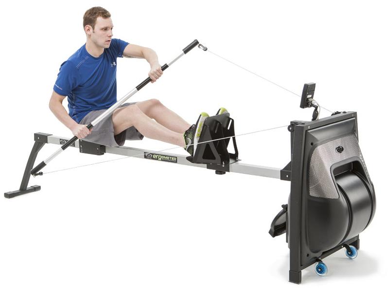
9 PART 2 USING THE VASA KAYAK ERGOMETER The following sections contain guidelines and tips for using your Vasa Kayak Ergometer, the Power Meter, and adjusting the resistance SAFE OPERATION GETTING SAFELY ON AND OFF CAUTION: Do not suddenly release the paddle shaft as they could strike the Power Meter or front assembly causing damage or injury. Always gently return the paddle shaft or handles to the ready position on the front assembly. 1) Take the kayak paddle shaft in both hands, have one leg on each side of the monorail and sit in the seat. 2) Bring one foot up and place it in the locked foot brace. *If you need to adjust the position of the foot brace for comfort, do so now. 3) Bring your second foot up into position and bring the kayak shaft into position. Keep your hands shoulder width apart and begin your workout. ➊ ➋ ➌ Vasa Kayak Ergometer User s Manual 9

10 SAFETY REMINDERS It s very important to use common sense and adhere to these safety guidelines in order to avoid injury to yourself or damage to your Vasa Kayak Ergometer. Please follow this pre-flight safety check prior to using your Vasa Kayak Ergometer: DO NOT let go of the PADDLE SHAFT while the drive cords are extended - they could hit and damage the unit. Always return the paddle to the start position. Always instruct bystanders, especially children, to keep totally clear while the Ergometer is in use, especially of the moving drive cords and flywheel. Keep eyes and hands clear of the air outlet below the damper door. To avoid blowing dust into the air, eyes or into the electronics, do not operate in a dusty area. Do not operate if the front assembly cover(s) have been removed. Do not pull the drive cords past the end of the rear stanchion. If the drive cords become difficult to pull (like the cord is stuck), do not continue to pull as this may damage your Ergometer. Perform proper maintenance on your Vasa Kayak Ergometer as recommended in Maintenance & Troubleshooting section. IMPORTANT: Do NOT pull the drive cord past the end of the Ergometer. It could damage the machine. POWER METER Do not release shaft or handles while using the Ergometer. They could damage the Power Meter. Do not force the Power Meter when adjusting it side to side or up and down. If necessary, loosen the clamp a bit before adjusting. AIR INLET Do not operate with plastic covers removed. DAMPER DOOR Keep eyes and hands clear of air outlet. Do not put anything through the holes of the perforation in the air inlet and air outlet. Be sure to loosen the lock knob before adjusting the damper door. 10 Vasa Kayak Ergometer User s Manual
11 SUPERVISING CHILDREN We recommend supervising children at all times while using the Vasa Kayak Ergometer. Please review the Safety Reminders and Getting On and Off Safely in this section with all children who will use the Vasa Kayak Ergometer. In addition, we recommend that children should train with or be instructed by a parent or coach whenever possible. This will help reduce the chance of injury. It also can be more motivating and fun. SECURING YOUR VASA KAYAK ERGOMETER IN A PUBLIC SETTING If your Vasa Kayak Ergometer is left in a public area, you may wish to secure or vandal-proof it to avoid unauthorized use. We recommend the following: 1. Remove any drive cord attachment (handles or kayak shaft). Store these and any other accessories in a secure place. 2. To deter unwanted use and protect your investment, keep your Vasa Kayak Ergometer covered when not in use. Covers are available at 3. Store the Vasa Kayak Ergometer in a dry, secure room or closet. Avoid storing it in a humid, chlorine or salt-air environment. MEDICAL CLEARANCE - See your Doctor before beginning any exercise program. CAUTION: Before exercising with the Vasa Kayak Ergometer or any other form of exercise, please check with your physician first. This is especially important if you are overweight, if you have been inactive for awhile, if you have injuries, or if you have any history of heart disease in your family. If you are over 35, it s a good idea to perform an exercise stress test with a qualified physician before you begin training. Training with the Vasa Kayak Ergometer can be vigorous and demanding. We suggest that you be in good health to achieve the best results. Vasa Kayak Ergometer User s Manual 11
12 2.2. SETTING THE RESISTANCE The flywheel and the damper door work in concert to affect the resistance you will feel using the Vasa Kayak Ergometer. FLYWHEEL The airflow resistance of the flywheel simulates the resistance of water - the harder you pull, the more resistance you feel. DAMPER DOOR You can adjust the airflow resistance by adjusting the damper door. The lowest setting 1 (door fully closed) provides the least resistance and setting 7 (door fully open) provides the most resistance. Setting #1 is similar to going WITH the current and Setting #7 is similar to going AGAINST a strong current. To adjust the damper door / change resistance level: 1. Unlock knob - turn counter-clockwise 2. Lift/Lower door (Settings: 1=easiest / 7=hardest) 3. Lock knob - turn clockwise 1 M O R E R E S DAMPER DOOR I S T A N C E SETTING #1 (door closed) Lowest/Easiest 7 SETTING #7 (door open) Highest/Hardest Figure A Figure B KNOB: Lock/Unlock 1 1 SETTING # Damper door setting number Lock door = turn clockwise Unlock door = turn counter-clockwise 12 Vasa Kayak Ergometer User s Manual
13 DAMPER DOOR SETTINGS RELATING TO POWER AND FORCE OUTPUT At high settings (5, 6, 7) it feels like paddling against a current. At low settings (1 & 2) it feels more like paddling with a current. So if you select a setting of 1, you will have to paddle faster than your normal speed in still water to generate the same power (faster stroke rate). If the you select a setting of 7, you will have to paddle slower than your normal speed in still water to generate the same power (slower stroke rate). Mathematically, this is expressed by the equation Power = Force x Velocity. The fan resistance determines the force (a higher setting is a higher force) and the paddle shaft speed is the velocity. So the same power can be achieved with either a high resistance setting combined with a low paddle shaft speed or a low resistance setting combined with a high paddle shaft speed. As you would expect, there will be a setting where an individual can produce the maximum power due to physiological and biomechanical efficiency, and this setting will likely be different depending on the individual s body and training. The Power Meter calculates power by sampling the force and shaft speed many times per second throughout the stroke. Therefore it calculates power produced & distance traveled precisely regardless of the damper door setting. This allows users to choose a damper door setting according to personal preference. It is important to remember that the damper door setting is subjective, depending on body type, conditioning level, and stroke technique. Suggestion: once per week for one month do a 500 meter or a 1000 meter time trial at race pace & race stroke rate. On week one, set the damper door at 2, for week 2, set it at 3 and so on. You ll discover the damper door setting that allows you to perform your best for that distance. Measure your heart rate, watts, and time. Monitoring these will help you arrive at the most efficient stroke rate, technique and heart rate to sustain the power and pace you need to improve. NOTE: Use the Audible Stroke Rate Tempo Beeper to help paddle at your desired stroke rate. For full details on the Audible Tempo Beeper, continue to the section on Power Meter Operation. Vasa Kayak Ergometer User s Manual 13
14 2.3. POWER METER - OPERATION The Power Meter gives you the opportunity to get instant feedback on your performance. You can measure time, distance, pace, stroke rate, stroke power (watts), and applied force for each side (Figure A). Having this information allows you to: monitor your progress create repeatable performance testing & training set up workouts based on time & distance perform intervals or distance training simulate races analyze force for right and left arms Specifics on how the power meter calculates this data can be found at the end of this section. INITIALIZE THE POWER METER STROKES PER MINUTE ON/OFF button Figure A 5:48 I05 I:25 /100M ELAPSED TIME ACCUMULATED DISTANCE PACE / 100M(SWIM) / 500M*(KAYAK) STROKE POWER Each time after you install the connection cables, you must: power OFF (by pushing the ON/OFF button) wait for delayed beep power ON This process will allow for the PM to communicate accurately with the Ergometer. If you see irregular readings, repeat the initialize steps above. VIEWING OPTIONS: KAYAK VS. SWIM There is a SWIM VIEW (default) and KAYAK VIEW on the Power Meter that provides relative data based on the sport. The upper left corner of the top screen will denotes the view. Swim View = no display/blank (Figure B) Kayak View = K displayed (Figure C) Swim Display is blank here Figure B 5:48 I05 I:25 /100M To change between views: Step 1: Begin with the power meter OFF. Step 2: Hold SHIFT and then press ON/OFF. Release buttons and wait for LCD test sequence to finish. Step 3: Hold SHIFT and then press ON/OFF so it will display a series of numbers. Release buttons. Step 4: Hold the SHIFT and press SETUP button. Release buttons. The display will turn off followed by a short beep. Step 5: Turn ON for the new view. Kayak Display shows K here The Power Meter will remain in the selected view (Swim or Kayak) for all future workouts until you change it back. Repeat the sequence above if you want to change to the other view. K Figure C 48: :00 /100M *PACING NOTE: In the Kayak View, the Power Meter will calculate PACE/500M. Swim View is always displayed in PACE/100M. 14 Vasa Kayak Ergometer User s Manual
15 MODES: BASIC VS. STROKE There are two main display modes on the Power Meter (PM): BASIC MODE and STROKE MODE (Figures D and E). When the PM is first turned on, it will automatically enter Basic Mode. Both Basic Mode and Stroke Mode give you readings on ELAPSED TIME, stroke rate (strokes per minute), and STROKE POWER (watts). The remaining fields are sub-displays that change by pressing the Display button. For more information on Basic Mode, Stroke Mode and their sub-displays, see the next two pages. To get into STROKE MODE, press and hold the blue button, then press and release the Down Arrow button (below STROKE - see Figure E). To return to BASIC MODE, press and hold the blue button, then press and release the Down Arrow button. Figure D - BASIC MODE STROKES / MINUTE :00 0 0:00 /100M 0 0 ELAPSED TIME STROKE POWER Figure E - STROKE MODE : FORCE 0 0 ELAPSED TIME STROKES / MINUTE STROKE POWER + SHIFT MODE = SHIFT + DOWN Vasa Kayak Ergometer User s Manual 15
16 BASIC MODE Basic Mode has three sub displays PACE, Power, and Calories. These sub-displays give you more specific information about your pace, your average power and the calories burned. You can choose these submodes by pressing the Display button (Figure D) on the Power Meter keypad. Each time the Display button is pressed, the display changes to the next mode. This can be done at any time without affecting the operation of the Power Meter. The top and bottom fields will always display the same information in all of the three sub-displays. The two middle fields will change as you press the Display button. The top field is ELAPSED TIME, the bottom left field is stroke rate in strokes per minute, and the bottom right field is STROKE power (in watts) for the last stroke (Figure D). Figure D ELAPSED TIME STROKES / MINUTE 5:48 I05 I:25 /100M PACE STROKE POWER See PACE NOTE below. ON/OFF button Display push display to get into sub-mode PACE NOTE: The pace calculation in Kayak Viewing Option reflects pace per 500M. The Swim Viewing Option reflects pace per 100M. NOTE: If the Power Meter (PM) senses the fan wheel is idle for 10 seconds, the PM will power down and you will lose your workout data. If you choose to PRE-SET YOUR TIME or DISTANCE, the PM will continue to retain data (see page 32 for full details). 16 Vasa Kayak Ergometer User s Manual
17 BASIC MODE SUB-DISPLAYS (PACE, POWER, CALORIE) Note: In all of the basic mode sub-displays, the two middle fields will change as you press the Display button. The other sub-displays (top and bottom fields) will display the same information. BASIC MODE > PACE (FIGURE E) In the pace display, the fields are as follows: Top: ELAPSED TIME since start of workout Second: TOTAL since start of workout Third: PACE per 500 * for the last stroke (Kayak) Bottom Right: STROKE POWER (watts) for the last stroke Bottom Left: STROKE RATE in strokes per minute BASIC MODE > POWER (FIGURE F) In the power display, the fields are as follows: BASIC MODE > PACE i6:40 i000 I:40 /100M Figure E ELAPSED TIME TOTAL PACE STROKE POWER STROKES / MINUTE Top: ELAPSED TIME since start of workout Second: AVERAGE POWER in watts since start Third: PACE per 100 * for the last stroke Bottom Right: STROKE POWER (watts) for the last stroke Bottom Left: STROKE RATE in strokes per minute * IN KAYAK VIEW: the Power Meter will calculate PACE /500M even though it is denotes it as /100M on the screen. BASIC MODE > CALORIE (Figure G) In the calorie display, the fields are as follows: Top: ELAPSED TIME since start of workout Second: TOTAL CALORIES since start of workout Third: AVG CAL / HOUR for the last stroke Bottom Right: STROKE POWER (watts) for the last stroke Bottom Left: STROKE RATE in strokes per minute BASIC MODE > POWER i6:40 AVG 63 I:40 /100M Figure F ELAPSED TIME AVERAGE POWER PACE STROKE POWER STROKES / MINUTE For more information on meters and pace, see the end of this section. BASIC MODE > CALORIE i6:40 CAL 366 CAL/HR i Figure G ELAPSED TIME TOTAL CALORIES AVG CAL / HR STROKE POWER STROKES / MINUTE Vasa Kayak Ergometer User s Manual 17
18 STROKE MODE Stroke Mode gives you more specific information about each stroke, and shows information for the left and right strokes separately. To get into STROKE MODE, press and hold the blue button, then press and release the Stroke (down arrow) button (Figure H). Stroke Mode has three sub-displays: Average Force, Maximum Force, and Stroke Length. You can choose these sub-modes by pressing the Display button on the power meter keypad (make sure you are in stroke mode first - see above). Each time the Display button is pressed, the display changes to the next mode. This can be done at any time without affecting the operation of the Power Meter. When in Stroke Mode, the top three fields always display the same information (the bottom left and right fields will change as you press the Display button). The top field is the ELAPSED TIME since the start of exercise, the second field is the stroke rate in strokes per minute, and the third field is the STROKE POWER (in watts) for the last stroke (Figure H). Figure H i6: FORCE ELAPSED TIME STROKES / MINUTE STROKE POWER on / off button Display push display to get into sub-mode + press and hold shift then press stroke (down arrow) 18 Vasa Kayak Ergometer User s Manual
19 STROKE MODE SUB-DISPLAYS (AVERAGE FORCE, MAX FORCE, STROKE LENGTH) Note: In all of the stroke mode sub-displays, only the bottom left and right fields will change as you press the Display button. The top three fields always display the same information. STROKE MODE > AVERAGE FORCE (Figure I) In the average force display, the fields are as follows: Top: ELAPSED TIME since start of workout Second: STROKE RATE in strokes per minute Third: STROKE POWER (watts) for the last stroke Bottom Right: AVERAGE FORCE 1 for right side Bottom Left: AVERAGE FORCE 1 for left side 1 average force: measures the force applied during the power portion of each stroke. The force is displayed in units of Newtons: (1 LB = 4.45 Newtons; 1 Newton = LBs). STROKE MODE > AVERAGE FORCE i6: FORCE 49 Figure I ELAPSED TIME STROKES / MIN STROKE POWER AVG FORCE RIGHT AVG FORCE LEFT STROKE MODE > MAX FORCE (Figure J) In the max force display, the fields are as follows: Top: ELAPSED TIME since start of workout Second: STROKE RATE in strokes per minute Third: STROKE POWER (watts) for the last stroke Bottom Right: MAX FORCE 2 for right side Bottom Left: MAX FORCE 2 for left side 2 MAX force: measures the maximum force applied at any instant during each stroke. The force is displayed in units of Newtons: (1 LB = 4.45 Newtons; 1 Newton = LBs). STROKE MODE > MAX FORCE i6: MAX FORCE Figure J ELAPSED TIME STROKES / MIN STROKE POWER MAX FORCE RIGHT MAX FORCE LEFT STROKE MODE > STROKE LENGTH (Figure K) In the stroke length display, the fields are as follows: Top: ELAPSED TIME since start of workout Second: STROKE RATE in strokes per minute Third: STROKE POWER (watts) for the last stroke Bottom Right: STROKE LENGTH 3 for right side Bottom Left: STROKE LENGTH 3 for left side 3 STROKE LENGTH is measured in centimeters. STROKE MODE > STROKE LENGTH SL ii0 i6: ii2 Figure K ELAPSED TIME STROKES / MIN STROKE POWER STROKE LENGTH R STROKE LENGTH L Vasa Kayak Ergometer User s Manual 19
20 POWER METER - SPECIAL FUNCTIONS SETTING UP A PRE-SET WORKOUT DISTANCE You can pre-set a distance (in meters) for your workout, and the Power Meter (PM) will count down the distance and display the total time to achieve that distance. To set the desired distance, push the SETUP button while in BASIC MODE. The left most number will be flashing (Figure A). Use the up or down arrows to change the flashing number. To move to the next number, use the right arrow. Once you have set the desired distance, press SETUP to exit. The PM will then wait until you begin your workout to start counting (Figure B). When the pre-set distance is completed, the PM will freeze so you can record the data (Figure C). (After 5 minutes of inactivity, the PM will auto shut off.) To begin again or to reset the distance, press SETUP twice. NOTE: The PM will default to BASIC > Pace Mode. To change to BASIC > Calorie, or BASIC > Power, press the Display button. Figure A Figure B Figure C SETUP BUTTON :00 i000 0:00 /100M 0 0 I6:40.0 I 00 0 I:40 /100M Setup ➊ push setup to set desired distance ➋ use arrows to set desired distance, then push setup to exit ➌ after setting your distance, the monitor will stay ready until you start your workout ➍ after completing the distance, the monitor will freeze so you can view and record the data USING THE POWER METER CLOCK FOR INTERVAL TRAINING, RACE SIMULATIONS AND TIMED PIECES You can use the Power Meter to do interval training, race simulation and set distance workouts. Set your desired interval distance as described above. Immediately after you have completed the first set, press the setup button twice (the flywheel must still be spinning). You can then watch the clock for your desired recovery or rest period. When you are ready for the next set, press the setup button twice to begin timing your next interval. (Of course, you can always use your own watch or pace clock to time rest periods between intervals.) 20 Vasa Kayak Ergometer User s Manual
21 SETTING UP WORKOUT INTERVALS: pre-set distance or time with rest interval for interval training, race simulations and distance workouts You can use the Power Meter to do interval training, race simulation and pre-set distance workouts. You can pre-set a DISTANCE (in meters) or a TIME (in minutes/seconds) for your workout. For interval training you can pre-set a REST INTERVAL between your exercise intervals. The Power Meter will count down the distance or time and rest intervals. When the workout is complete, the Power Meter will display the total time and distance covered. If you want to pre-set SPLITS and REVIEW each interval, see Setting Split Times and Workout Review on page 23. INTERVAL TRAINING: pre-set distance with rest interval To set the desired distance, press the SETUP button. The first display will be DISTANCE (Figure A). With DISTANCE in the display (Figure A), use the up down and right arrows to change the flashing number to the desired distance. Note: you must be in BASIC MODE to program intervals. After pressing SETUP, press DISPLAY to toggle between DISTANCE, REST TIME for distance intervals, TIME, and REST TIME for time intervals. After setting the desired distance, ➋ press DISPLAY to set the REST interval. With REST in the display (Figure B), use the arrows to set the desired rest time. Once you have set the desired workout, ➌ press SETUP to exit. As soon as you pull on the drive cords the monitor will start counting down the distance (Figure C). When the first distance interval is completed, the monitor will count down the rest interval (Figure D). When the rest interval is complete, the monitor will stay ready for the next distance interval (Figure C). When you have completed your workout, you can review all intervals by pressing REVIEW (see Workout Review on p. 23). Press the up/down arrows to see the next interval. NOTE: To pre-set splits for your interval workout, see Setting Split Times / Distances on p. 23. Figure A Figure B Figure C Figure D SETUP BUTTON :00 REST :00 i00 0:00 /100M 0 0 DISTANCE i:22.3 i00 REST : REST INTERVAL ➊ Setup push setup then use arrows to set distance press display to set rest interval Display 1 DISTANCE ➋ Display Display 2 REST INTERVAL ➌ Setup after programming distance and rest interval, press setup to exit the monitor will stay ready until you begin your workout once you pull on the drive cords, it will begin counting down the distance after completing the distance, the monitor will count down the rest interval and display results from recent interval workout Vasa Kayak Ergometer User s Manual 21
22 INTERVAL TRAINING: pre-set time with rest interval ➊ To set the desired time, press the SETUP button, then press DISPLAY (twice) until time is displayed in the top field (Figure A). Use the arrows to change the flashing number to the desired time. Note: you must be in BASIC MODE to program intervals. After pressing SETUP, press DISPLAY to toggle between DISTANCE, REST TIME for distance intervals, TIME, and REST TIME for time intervals. After setting the desired time, ➋ press DISPLAY (once) to set the REST interval. With REST in the display (Figure B), use the arrows to set the desired rest interval. Once you have set the desired workout, ➌ press SETUP to exit. As soon as you pull on the drive cords the monitor will start counting down the time (Figure C). When the first interval is completed, the monitor will countdown the rest interval (Figure D). When the rest interval is complete, the monitor will stay ready for the next time interval (Figure C). When you have completed your workout, you can review all intervals by pressing REVIEW (see Workout Review on p. 23). Press the up/down arrows to see the next interval. NOTE: To pre-set splits for your interval workout, see Setting Split Times / Distances on p. 23. Figure A Figure B Figure C Figure D SETUP BUTTON ➊ Setup 0:00:00 0:00 REST 5: :00 /100M 0 0 5: REST I: push setup then display until time appears in top field then use arrows to set numbers press display to set rest interval Display 3 TIME ➋ Display Display 4 REST INTERVAL ➌ Setup after programming time and rest interval, press setup to exit the monitor will stay ready until you begin your workout once you pull on the drive cords, it will begin counting down the time after completing the time interval, the monitor will count down the rest interval 22 Vasa Kayak Ergometer User s Manual
23 SETTING SPLIT TIMES / DISTANCES Default split times are pre-set at 50 meters and 30 seconds. If want to change the defaults, press SETUP then REVIEW. The distance split interval is shown first (Figure A). Press DISPLAY to show the time split interval (Figure B). Use the arrow buttons to select a different split interval. NOTE: The split times will reset back to the defaults when the Power Meter is turned off. Figure A Figure B ➊ Split Distances: 25M 50M (default) 100M 200M 1000M Setup ➋ Review SPL 50 0:30 SPL Split Times: :30 sec (default) 1:00 min 2:00 min 3:00 min 4:00 min 5:00 min 10:00 min push setup then review to change defaults DISTANCE TIME use arrows to set desired splits press display to toggle between distance and time splits WORKOUT REVIEW The Power Meter contains a workout review feature that will store up to 20 splits +/or intervals. After you complete your workout, the Power Meter will display (Figure C) your TIME, DISTANCE, AVERAGE PACE* and STROKES / MINUTE for the most recent interval. Figure C * Pace is dependent on which view (Swim vs. Kayak) you are in. Swim view will display pace /100M while Kayak view will display pace /500M To review the information for each split, press the REVIEW button. To review next split, press the UP and DOWN arrows. The split information shown is (Figure D): Top: TIME of the interval Second: distance of the interval Third: average pace / 100m (or /500M) for the interval Bottom Left: INTERVAL number 2:06.5 i00 2:06 /100M 29 Note: After 5 minutes of inactivity, the monitor will auto shut off and clear your workout data. Figure D Example of a 100M workout with 25M splits /100M I i:i i:40 /100M 2 i:4i.5 75 i:38 /100M 3 2:06.5 i00 i:40 /100M 4 Split #1 Split #2 Split #3 Split #4 Vasa Kayak Ergometer User s Manual 23
24 AUDIBLE STROKE RATE TEMPO BEEPER The Power Meter contains an audible stroke rate tempo beeper, which allows you to set a desired stroke rate (strokes per minute) and keep pace by listening to the beeper tone tempo. To set the tempo beeper, press and hold SHIFT, then press TEMPO (up arrow ) (Figure D). Set the desired stroke rate per minute using the up, down and right arrow keys. To exit, press and hold SHIFT, then press TEMPO (up arrow ). The Power Meter will beep every cycle, according to the STROKE RATE () you set. To turn the beeper sound off, press and hold SHIFT, then press the horn button ( right arrow ) (Figure E). The beeper will automatically turn off when the Power Meter is off. Figure D Figure E 030 :00 0 0:00 /100M 0 0 ➊ use arrows to set + ➋ desired stroke rate + press and hold SHIFT, then press TEMPO (up arrow) ➌ to turn the beeper on and off, press and hold SHIFT, then press (right arrow) SOFTWARE VERSION You can display the software version of your Power Meter to check if you have the most current version of the software. While the power is OFF, press and hold SHIFT, then press POWER. All LCD segments will display for a moment, then the version number will be displayed in the top field. 0I23 F6C6 ➊ + press and hold SHIFT, then press POWER S h i f t S e t u p R e v i e w D i s p l a y 24 Vasa Kayak Ergometer User s Manual
25 BATTERY REPLACEMENT The batteries in your Vasa Kayak Ergometer Power Meter should last about 600 hours. When you see LOW CELLS in the top two fields of your Power Meter, the batteries should be changed. To change the batteries, open the battery compartment on the back of the Power Meter (Figure A). The Power Meter takes two AA batteries (alkaline are fine). IMPORTANT: PLEASE REMOVE THE BATTERIES from the Power Meter if it will not be used for 3+ months. BATTERY SAVE FEATURE There is a 5 minute time-out feature on your Power Meter. If there is no activity the Power Meter will power down after 5 minutes ( activity includes inputs from pulling on the drive cord, pushing buttons, or serial communications with a computer). Any workout information will be cleared from the memory as soon as the Power Meter shuts off. RE-ZERO POWER METER ONCE CONNECTED TO CABLES You should RE-ZERO the Power Meter every time it is reconnected to the connection cables (i.e. batteries replaced, removed from machine, etc.). To RE-ZERO, follow these steps: 1. Plug in the cables to the Power Meter (PM) and make sure they are seated correctly into the jacks; 2. Turn the PM OFF until you hear a short beep ; 3. Turn the PM ON by pressing the ON/OFF button. DO NOT PULL on the cords. 4. Turn the PM OFF again (wait for short beep ). 5. The PM is ready to use - press ON or just exercising. REMOVING THE POWER METER It is NOT recommended that you remove the Power Meter from the Vasa Kayak Ergometer on a regular basis. If you need to remove the Power Meter, it is suggested that you remove the batteries. When you reconnect the Power Meter make sure to follow the RE-ZERO procedures stated above. NOTE: Prior to disconnecting the connection cables, power the Power Meter OFF and wait for the delayed beep to ensure the computer has properly shut down. Disconnecting prior to this can cause the Power Meter to display irregular data. ODOMETER The odometer function allows you to track total swim distance, total kayak distance, time in seconds and left and right arm strokes on your Vasa Kayak Ergometer. To display the odometer, press and hold SHIFT, then press DISPLAY. Use the DISPLAY button to cycle through the various totals: 0 I695 Display #0 Display #1 Display #2 Display #3 Display #4 Display #5 Display #6 Total SWIM Total KAYAK Total SECONDS IN OPERATION Total STROKES / LEFT SIDE Total STROKES / RIGHT SIDE Total TACKS # LEFT (Vasa use only) Total TACKS # RIGHT (Vasa use only) Press and hold SHIFT and DISPLAY to activate the odometer. Then cycle through all totals by pressing DISPLAY. + Display Display Vasa Kayak Ergometer User s Manual 25
26 AND PACE CALCULATIONS The Vasa Ergometer Power Meter simulates the performance of the athlete by measuring the force (many times per second) during a stroke and powering a model through the water using that information. During each increment the Power Meter calculates the distance covered (kayaker/swimmer depending on which mode you are in) in that increment and adds that to the total distance. The display field shows that total distance. The Power Meter also keeps track of the distance and time at the start of each stroke and uses this information to calculate the average pace during that stroke. Pace is displayed in the /100M (swim view) and /500M (kayak view). NOTE: Pace and distance accumulated are calculated to approximate the pace and distance. DEFINITION OF STROKE The Vasa Ergometer Power Meter defines a stroke as the completion of one arm/paddle cycle. ALTERNATING ARM STROKES (freestyle, Nordic single poling, surf paddling, kayak/canoe padding). One stroke would be the complete of one cycle of both the left and right arms. The Power Meter will start collecting data on whichever side you start the first pull (left or right). SIMULTANEOUS ARM STROKES (butterfly, breaststroke, Nordic double poling) One stroke would be the completion of one cycle, from entry through recovery with both arms NOTE: If you change they type of stroke during a workout (from double arm to alternating arms, or vice versa), the Power Meter will auto detect the change and adjust the stroke data within 2 or 3 stroke cycles. 26 Vasa Kayak Ergometer User s Manual
27 SUMMARY OF FUNCTIONS AUTO START: As soon as you pull on the drive cords, the monitor will automatically turn on and begin monitoring your performance. It will automatically enter Basic Mode > Pace (see chart below). You can reset the monitor using the ON/OFF button. IMPORTANT: PLEASE REMOVE THE BATTERIES from the monitor if it will not be used for 3+ months. VIEWING OPTIONS: SWIM vs. KAYAK (p. 14): SWIM VIEW is the default viewing mode. If you are in KAYAK VIEW there will be a K in the upper left corner of the top screen. No notation is displayed while in SWIM VIEW. If you wish to change to the KAYAK VIEW follow the steps listed on page 14. *PLEASE NOTE: Pace is relevant to the view: SWIM VIEW= pace/100m while KAYAK VIEW= pace/500m. BASIC MODE (p. 16): Basic Mode has three sub-displays: PACE*, POWER, and CALORIES. Choose sub-modes by pressing the Display button. BASIC MODE VM Field: BASIC > PACE BASIC > POWER BASIC > CALORIE TOP ELAPSED TIME since start ELAPSED TIME since start ELAPSED TIME since start SECOND TOTAL since start AVERAGE POWER since start TOTAL CALORIES since start THIRD PACE /100M* for last stroke PACE / 100M* for last stroke AVG CAL / HOUR for last stroke BOTTOM Right POWER (watts) for last stroke POWER (watts) for last stroke POWER (watts) for last stroke BOTTOM Left STROKE RATE in strokes / min STROKE RATE in strokes / min STROKE RATE in strokes / min STROKE MODE (p. 18): To get into STROKE MODE, press and hold the blue button, then press and release the Down Arrow button. Stroke Mode has three sub-displays: AVERAGE FORCE, MAXIMUM FORCE, and STROKE LENGTH. Choose sub-modes by pressing the Display button. STROKE MODE VM Field: STROKE > AVG FORCE STROKE > MAX FORCE STROKE > STROKE LENGTH TOP ELAPSED TIME since start ELAPSED TIME since start ELAPSED TIME since start SECOND STROKE RATE in strokes / min STROKE RATE in strokes / min STROKE RATE in strokes / min THIRD POWER (watts) for last stroke POWER (watts) for last stroke POWER (watts) for last stroke BOTTOM Right AVG FORCE for right side MAX FORCE for right side STROKE LENGTH for right side BOTTOM Left AVG FORCE for left side MAX FORCE for left side STROKE LENGTH for left side INTERVAL TRAINING (p. 20): To pre-set a desired distance, time, and rest interval push the SETUP button (you must be in BASIC MODE). Pressing DISPLAY will toggle between DISTANCE, REST TIME for distance intervals, TIME, and REST TIME for time intervals. Use the arrows to change the flashing number. Once you have set the desired workout press SETUP to exit. SETTING SPLIT TIMES / DISTANCE (p. 23): Default split times are pre-set at 50m and 30 sec. If want to change the defaults, press SETUP then REVIEW (Figure C). Use the arrow buttons to change the defaults. Press DISPLAY to toggle between DISTANCE splits and TIME splits. WORKOUT REVIEW (p. 23): The Power Meter contains a workout review feature that will store up to 20 splits. After you complete your workout, the Power Meter will freeze. To review the information for each split, press the REVIEW button. Then, to review each split, press the UP and DOWN arrows. AUDIBLE STROKE RATE TEMPO COUNTER (p. 24): To set the tempo beeper, press and hold SHIFT, then press TEMPO (up arrow ). Set the desired STROKE RATE () using the arrow keys. To exit, press and hold SHIFT, then press TEMPO. RE-ZERO MONITOR (p. 25): RE-ZERO the monitor if the connection cables have been disconnected for any reason. Connect cables, turn POWER OFF and wait for delayed beep. Turn POWER ON (do not pull on cords). Power back OFF and wait for delayed beep. Complete and ready for use. Vasa Kayak Ergometer User s Manual 27
28 TRAINING LOG Monday Tuesday Wednesday Thursday Friday Saturday Sunday Date PURPOSE (Endurance, Power, Intervals, Time Trial) Total Time Total Meters Heart Rate Work Time or Work Distance Rest Time (intervals) Damper Setting PACE Strokes / Minute Pace / 500M (kayak view) POWER Max Watts Average Watts CALORIES Total Calories Avg Calories / HR FORCE Avg Force Left Avg Force Right Max Force Left Max Force Right STROKE LENGTH (cm) Stroke Length Left Stroke Length Right TOTALS THIS WEEK Comments: 28 Vasa Kayak Ergometer User s Manual
29 TRAINING NOTES Vasa Kayak Ergometer User s Manual 29
30 MAINTENANCE PART 3 - MAINTENANCE & TROUBLESHOOTING Regular maintenance of your Vasa Kayak Ergometer is an important component of years of enjoyable, functional, and safe use of your machine. Maintenance requirements will vary considerably depending on how much use your Vasa Ergometer gets. Please read the following guidelines carefully as these recommendations are made to help you maintain your Vasa Ergometer most effectively. Follow the maintenance steps suggested on the next page based on the amount of use. HIGH CHLORINE & HIGH HUMIDITY = HIGH MAINTENANCE Unfortunately, steel does not fare well in humid, highly chlorinated environments at pool-side or outside in humid, salty ocean air. If your Vasa Kayak Ergometer is located in such inhospitable environments, it is extremely important for you to perform the maintenance steps on the next page at least once each month. If you use your Vasa Kayak Ergometer on the deck of a pool, be sure to place a rubber mat under the machine to prevent it from slipping and to prevent contact with water from the pool. DO NOT use the Ergometer directly on the concrete surface of a pool deck without a rubber mat between the machine and the concrete floor. HIGH HUMIDITY CHLORINE OCEAN AIR UV LIGHT WARNING Use of the Vasa Kayak Ergometer in humid, chlorinated, or salt air environments will void the lifetime guarantee. STORAGE We recommend storing your Ergometer in a dry, indoor environment, away from a humid and/or chlorinated climate. The Vasa Kayak Ergometer is not designed to be left outdoors in the elements of direct sunlight, rain, or ocean air. If you must leave your Ergometer outdoors, either cover completely with a waterproof cover or remove the Power Meter, paddle shaft/handles, and take them inside. Cover the rest of the machine with a cover to minimize moisture collection on the metal parts. SECURING THE VASA KAYAK ERGOMETER IN CLUBS, SCHOOLS, ETC. Clubs, teams, schools, etc. may want to keep their Vasa Kayak Ergometers set up in the gym or training facility, yet will not want to risk injury to students, vandalism or theft of key parts. We suggest that you remove the Power Meter and the paddles/handles and lock these in a safe place between training sessions. A cover also works well to deter unauthorized use. 30 Vasa Kayak Ergometer User s Manual PART 3 - Maintenance & Troubleshooting
 FRONT COVER MOUNTING BRACKET DRIVE CORD fan housing DRIVE SPOOL (BLACK SPOOL & WHITE SPOOL) LOAD CELL LOAD CELL MOUNTING BRACKET REWIND SHOCK CORD / REWIND")
31 GETTING TO KNOW YOUR VASA KAYAK ERGOMETER FRONT COVER WITH AIR INLET SCREEN DAMPER DOOR WITH AIR OUTLET SCREEN front end assembly - front (inlet) cover removed FRONT END FRAME WELDMENT monitor connection cable (part of the load cell) FRONT COVER MOUNTING BRACKET DRIVE CORD fan housing DRIVE SPOOL (BLACK SPOOL & WHITE SPOOL) LOAD CELL LOAD CELL MOUNTING BRACKET REWIND SHOCK CORD / REWIND SYSTEM CAUTION: Do NOT attempt to remove the cords without proper instruction. The rewind cord is under tension. FRONT COVER MOUNTING BRACKET WHEELS MOUNTED ON WHEEL BRACKET Vasa Kayak Ergometer User s Manual PART 3 - Maintenance & Troubleshooting 31
32 MAINTENANCE SCHEDULE & DETAILS To keep your Vasa Kayak Ergometer working at its best, please follow the suggested maintenance schedule. The chart below outlines a general plan based on hours of use. Replacement parts can be purchased at or by calling us directly at (US only). International customers please call TEAM / CLUB USE 10+ hours per week (Heavy Use) PERSONAL / HOME USE Less then 10 hours per week (Light to Moderate Use) DAILY 1. Clean monorail N/A WEEKLY 1. Clean entire machine. 2. Inspect paddles. 1. Clean monorail. MONTHLY 3 MONTHS 6 MONTHS 1. Repeat WEEKLY steps. 2. Monitor dust/dirt buildup in air inlet & outlet areas. Vacuum as needed. 3. Monitor drive shaft & lubricate with lithium grease as needed. 1. Repeat MONTHLY maintenance. 2. Inspect drive cord & clips for wear. Replace as needed. 3. Inspect rewind shock cord for wear. Replace as needed. - IN HARSH or HUMID ENVIRONMENTS - 4. Apply lithium grease to screw threads on all nuts & bolts. This will help prevent corrosion and rust. 1. Repeat MONTHLY and 3 MONTH maintenance. 2. Replace two AA batteries in monitor. 1. Clean entire machine. 2. Inspect paddles. 1. Repeat MONTHLY maintenance. 2. Monitor dust/dirt buildup in air inlet & outlet areas. Vacuum as needed. 4. Monitor drive shaft & lubricate with lithium grease as needed. 1. Repeat MONTHLY and 3 MONTH maintenance. 2. Inspect drive cord & clips for wear. Replace as needed. 3. Inspect rewind shock cord for wear. Replace as needed. CLEANING THE ENTIRE MACHINE - Thoroughly clean entire machine with a rag or hand towel and multi-purpose cleaner. Clean the monorail as detailed above (do NOT use abrasive cleaner). PADDLE SHAFTS - Inspect paddles for wear on connection joints. If signs of wear, replace immediately. CLEANING AIR INLET/OUTLET SCREENS - Monitor the dust build-up on air inlet and outlet areas (perforated metal located on the front assembly cover and under the damper door cover). Vacuum as needed. Diagrams and detailed instruction on page 76. DRIVE SHAFT LUBRICATION - Apply a layer of lithium grease along the entire surface of the Drive Shaft to prevent corrosion & rust. Diagrams and detailed instruction on page 76. DRIVE CORD REPLACEMENT - Worn drive cord should be replaced with new cord. Signs of wear include fraying threads or any cuts in the cord. It is recommended to replace the Drive Cord Clips and Rewind Shock Cord at the same time. DRIVE CORD CLIP REPLACEMENT - Replacement of the drive cord clips is needed when the clips are broken. It is also HIGHLY recommended when you replace the Drive Cord. REWIND SHOCK CORD REPLACEMENT - The rewind shock cord should be replaced with new cord when it shows signs of wear or has lost its elastic properties. Inspect the cord by removing the front assembly cover. The rewind cord is the black or blue cord that is wrapped around the Drive Spools. LUBRICATION OF HARDWARE - Apply lithium grease or thick oil to all screw threads on all nuts & bolts. This will help prevent corrosion and rust. 32 Vasa Kayak Ergometer User s Manual PART 3 - Maintenance & Troubleshooting
488-VASA DRIVE SHAFT, FLYWHEEL, AIR INLET & OUTLET MAINTENANCE As part of the Vasa Kayak Ergometer maintenance program, we suggest regular maintenace of a few parts inside the front end")
33 Vasa Inc. 1(800)488-VASA DRIVE SHAFT, FLYWHEEL, AIR INLET & OUTLET MAINTENANCE As part of the Vasa Kayak Ergometer maintenance program, we suggest regular maintenace of a few parts inside the front end assembly. This will require removal of the front cover. Locate the four screws in the upper and lower corners on the front cover of the front end assembly (Figure A). Use the 5/32 allen wrench to remove the four screws. 1. Locate the Flywheel (Figure B). Vacuum both the right and left side of the fan to remove any dust that may have built up. Perform this step more or less frequently based on your environment. 2. HUMID, OUTSIDE or POOL SIDE ENVIRONMENTS: Locate the Drive Shaft (Figure B). Inspect the left and right sides to see if it is getting dry or discolored. If so, apply lithium grease to protect the finish. 3. Locate the Air Inlet & Air Outlet (Figure C). Vacuum the perforated metal areas to remove any dust buildup. 4. Replace the plastic cover. Slide it into position then replace the four screws in each corner. Tighten with 5/32 allen wrench. Figure A Figure B Figure C ERGOMETER FRONT COVER DRIVE SHAFT (LEFT SIDE) Grease BOTH sides VACUUM AIR INLET remove four screws with 5/32 allen wrench FLYWHEEL (LEFT SIDE) Vacuum Left & Right side of flywheel VACUUM AIR OUTLET POWER METER - MAINTENANCE battery compartment BATTERY REPLACEMENT The batteries in the Power Meter (PM) typically last about 600 working hours. If LO CELL appears in the top field of the PM, the batteries need to be replaced. To change the batteries, open the battery compartment on the back of the PM (Figure A). The Power Meter takes two AA batteries. + AA battery AA battery + NOTE: Static discharge may cause the Power Meter to inadvertently turn on. This will reduce the life of the batteries as the Power Meter will remain on for 5 minutes until the Battery Save feature is activated. BATTERY SAVE FEATURE There is a 5 minute time-out feature on your Power Meter. If there is no activity the Power Meter will power down after 5 minutes ( activity includes inputs from pulling on the drive cord, pushing buttons, or serial communications with a computer). Any workout information will be cleared from the memory as soon as the Power Meter shuts off. IMPORTANT: The Power Meter is a sealed unit. DO NOT take apart. Any attempt to disassemble will void warranty. Vasa Kayak Ergometer User s Manual PART 3 - Maintenance & Troubleshooting 33
USER S MANUAL. PART 6 - Vasa Extras Accessories & Replacement Parts
 SwimErg USER S MANUAL PART 1 - Assembly... 2 Parts List and Parts Descriptions... 2 Assembly Instructions... 3-9 Power Meter Installation...10-11 Post-Assembly Safety Checklist... 12 Recording Order Information...
MAGNETIC CYCLING TRAINER SF-B0419 USER MANUAL
 MAGNETIC CYCLING TRAINER SF-B049 USER MANUAL IMPORTANT: Read all instructions carefully before using this product. Retain owner s manual for future reference. For customer service, please contact: support@sunnyhealthfitness.com
CLASS CYCLE P8000 OWNER'S MANUAL JOHNSON HEALTH TECH. CO., LTD.
 CLASS CYCLE P8000 JOHNSON HEALTH TECH. CO., LTD. No.26, Ching Chuan Rd., Taya Hsiang, Taichung Hsien 428, Taiwan, R.O.C. TEL: +886-4-2566700 FAX: +886-4-2560087 E-mail: sales@johnsonfitness.com http://www.johnsonfitness.com
Misaligned Folds Paper Feed Problems Double Feeds Won t Feed FLYER Won t Run iii
 Operator s Manual Table of Contents Operator Safety... 1 Introduction... 2 Unpacking and Setup... 3 Unpacking... 3 Setup... 4 FLYER Overview... 5 FLYER Diagram... 5 Capabilities... 5 Control Panel... 6
 www.myrower.com support@myrower.com ASSEMBLY Congratulations on purchasing the MyRower! Please see the following pages for instructions on assembling your MyRower. Bits bag contents: Rail Cross Bolt (90mm)
DeskCycle USER S MANUAL. Ellipse QUESTIONS / PROBLEMS. Order# Support and Contact: See the support link at DeskCycle.com
 DeskCycle Ellipse USER S MANUAL Visit us at www.deskcycle.com for: Usage Tips Calorie Calculator Accessories And More QUESTIONS / PROBLEMS Order# Support and Contact: See the support link at DeskCycle.com
MAGNETIC MINI EXERCISE BIKE SF-B0418 USER MANUAL
 MAGNETIC MINI EXERCISE BIKE SF-B018 USER MANUAL IMPORTANT! Please retain owner s manual for maintenance and adjustment instructions. Your satisfaction is very important to us, PLEASE DO NOT RETURN UNTIL
USER S MANUAL QUESTIONS? CAUTION. Model No. FMEX Serial No. Write the serial number in the space above for reference. Serial Number Decal
 Model No. FMEX81110.0 Serial No. Write the serial number in the space above for reference. USER S MANUAL Serial Number Decal QUESTIONS? If you have questions, or if parts are damaged or missing, please
222 Schwinn Recumbent Exercise Bike Parts List Full Size Hardware Chart Product Illustration Assembly Instructions
 222 Schwinn Recumbent Exercise Bike Parts List Full Size Hardware Chart Product Illustration Assembly Instructions FITNESS SAFEGUARDS AND WARNINGS Before starting any exercise program, consult with your
Read Before Operating!
 Read Before Operating! IMPORTANT OPERATING INSTRUCTIONS THE DEUCE PITCHING MACHINE THROWS REAL REGULATION BALLS; HOWEVER, THE ACCURACY OF THE DEUCE DEPENDS ON THE QUALITY, HARDNESS AND TYPE OF BALLS YOU
Arena by Oregon Scientific
 Arena by Oregon Scientific 1 Model: SW288 User Manual Arena by Oregon Scientific SWIMWATCH (SW288) USER MANUAL CONTENTS Introduction... 3 Control buttons... 3 LCD... 4 Getting started... 5 Activate watch
Final Assembly Instructions Bikes with Threaded Headsets
 Final Assembly Instructions Bikes with Threaded Headsets Thank you for buying your new bicycle from L.L.Bean. Read these instructions carefully before beginning the final assembly. Prior to shipping, our
PROPORTIONING VALVE. Model 150 INSTRUCTION MANUAL. March 2017 IMS Company Stafford Road
 PROPORTIONING VALVE Model 150 INSTRUCTION MANUAL March 2017 IMS Company 10373 Stafford Road Telephone: (440) 543-1615 Fax: (440) 543-1069 Email: sales@imscompany.com 1 Introduction IMS Company reserves
Inside Front cover This page will remain blank.
 Owner s Manual Inside Front cover This page will remain blank. 1 Table of Contents Parts of the AirCAT...3 Assembling the AirCAT...4 Attaching the wheels to the stand...4 Attaching the battery box to the
7130 Lancer Rear Drive Magnetic Commercial Indoor Cycling Bike
 7130 Lancer Rear Drive Magnetic Commercial Indoor Cycling Bike Owner s Manual Made in Taiwan INDEX IMPORTANT SAFETY INFORMATION... 1 EXPLODED DRAWING... 2 PARTS LIST... 3 ASSEMBLY INSTRUCTION... 4-9 USER
BELT DRIVE INDOOR CYCLING BIKE SF-B1712 USER MANUAL
 BELT DRIVE INDOOR CYCLING BIKE SF-B1712 USER MANUAL IMPORTANT! Please retain owner s manual for maintenance and adjustment instructions. Your satisfaction is very important to us, PLEASE DO NOT RETURN
Read Before Operating!
 Read Before Operating! IMPORTANT OPERATING INSTRUCTIONS THE DEUCE PITCHING MACHINE THROWS REAL REGULATION BALLS; HOWEVER, THE ACCURACY OF THE DEUCE DEPENDS ON THE QUALITY, HARDNESS AND TYPE OF BALLS YOU
Final Assembly Instructions Bikes with Quill Stems
 Final Assembly Instructions Bikes with Quill Stems Thank you for buying your new bicycle from L.L.Bean. Read these instructions carefully before beginning the final assembly. Prior to shipping, our expert
S4W PRO ROBOT. User Manual. paddlepalace.com
 S4W PRO ROBOT paddlepalace.com 800-547-5891 503-777-2266 S4W Pro Taking Robot Technology to the Next Level The Paddle Palace S4W Pro takes robot technology to the next level. This innovative robot has
INDOOR BIKE MANUAL
 INDOOR BIKE 91022 MANUAL 91022 INSTRUCTIONS FOR USE 1) The model 91022 is designed to be used as light commercial use or home use. It has a fixed wheel driven flywheel and should be used under professional
G2W PRO ROBOT. User Manual. paddlepalace.com
 G2W PRO ROBOT paddlepalace.com 1-800-547-5891 503-777-2266 Putting Robot Technology to Work for You The Paddle Palace G2W Pro robot is everything you need in a robot! This robot has two throw wheels with
Duo/Trio Office Bike Owner s Manual
 Duo/Trio Office Bike Owner s Manual Welcome Congratulations on choosing to enhance your productivity and wellness with LifeSpan. You ve made a healthy decision, as the need for increased amounts of daily
! WARNING! IMPORTANT HPA AIR TANK SAFETY INSTRUCTION AND GUIDELINES ! WARNING! IMPORTANT SAFETY INSTRUCTION AND GUIDELINES
 ! WARNING! IMPORTANT SAFETY INSTRUCTION AND GUIDELINES! WARNING! IMPORTANT HPA AIR TANK SAFETY INSTRUCTION AND GUIDELINES This Paintball Marker is NOT A TOY. Misuse can cause serious injury or death. It
Fiber Cable Puller with Tuf-Lugger lite
 7 OPERATING INSTRUCTION MANUAL Fiber Cable Puller with Tuf-Lugger lite Copyright 2015 DCD Design & Manufacturing Ltd. Revision 1.0 IMPORTANT SAFETY INSTRUCTIONS READ ALL INSTRUCTIONS BEFORE USING The Fiber
Final Assembly Instructions Bikes with Threaded Headsets
 Final Assembly Instructions Bikes with Threaded Headsets Thank you for buying your new bicycle from L.L.Bean. Read these instructions carefully before beginning the final assembly. Prior to shipping, our
Pedometer with PC download. Model: FB322 OVERVIEW FRONT VIEW INDEX
 OVERVIEW FRONT VIEW Pedometer with PC download INDEX Model: FB322 Introduction...1 Overview...1 Front view...1 Back view battery compartment...1 LCD screen...1 Getting started...2 Setting the device...2
Magnetic Bike. Model No: AENERGISER BODY WORX. Retain this owner s manual for future reference Read and follow all instructions in this owner s manual
 BODY WORX Magnetic Bike Model No: AENERGISER Retain this owner s manual for future reference Read and follow all instructions in this owner s manual Version A 1 EXPLODE DRAWING -02- PARTS LIST AND TOOLS
2,500/4,000 LB Easy Riser Vertical Cable Feighner Lift
 2,500/4,000 LB Easy Riser Vertical Cable Feighner Lift CAUTION - PUT SAFETY FIRST 1. Before attempting to install or operate this lift, study and fully understand the proper operating procedures and safety
Training with the Seattle Wooden Rower. Contents CAUTION CAUTION. 1. Carton contents of the Seattle Wooden Rower. 2. Assembly.
 Training with the Seattle Wooden Rower Contents. As with any piece of fitness equipment, consult a physician before starting your exercise program.. Follow instructions provided in this manual for correct
T-016 ASSEMBLY MANUAL MODEL ROCK AND ROLL Main Street NE Minneapolis, MN
 MODEL T-016 ASSEMBLY MANUAL ROCK AND ROLL 5280 Main Street NE Minneapolis, MN 55421 1.877.226.7824 www.kurtkinetic.com COMPONENTS Tools Required for Assembly: 17mm Wrench or Adjustable Wrench When unpacking,
TrekMill USER'S MANUAL MM5050
 Read the safety and comfort guide in this manual before using this equipment. USER'S MANUAL TrekMill MM5050 Serial Number: Date Purchased: Find the serial number in the location shown below. CONTENTS Safety
BMR 2100XL Operating Instructions Page 1 of 13
 BMR 2100XL Operating Instructions Page 1 of 13 Thank you for deciding to purchase a Swisswing BMR 2100XL (Biomechanical Stimulation Device will be referred to in these operating instructions as the BMR).
Final Assembly Instructions Bikes with 16 Wheel Size
 Final Assembly Instructions Bikes with 16 Wheel Size Thank you for buying your new bicycle from L.L.Bean. Read these instructions carefully before beginning the final assembly. Prior to shipping, our expert
LUBRICATOR ASSEMBLY AND OPERATING INSTRUCTIONS
 AIR FILTER, REGULATOR AND LUBRICATOR 4035 ASSEMBLY AND OPERATING INSTRUCTIONS 349 Mission Oaks Blvd., Camarillo, CA 930 Visit our Web site at http://www.harborfreight.com Copyright 004 by Harbor Freight
Model PSI Compressor with 3-Gallon Air Tank 12VDC
 Model 6350 150 PSI Compressor with 3-Gallon Air Tank 12VDC IMPORTANT: It is essential that you and any other operator of this product read and understandd the contents of this manual before installing
Heavy Duty Dissolved Oxygen Meter
 User's Manual Heavy Duty Dissolved Oxygen Meter Model 407510 Test Equipment Depot - 800.517.8431-99 Washington Street Melrose, MA 02176 FAX 781.665.0780 - TestEquipmentDepot.com Introduction Congratulations
BR-2444 ROWING MACHINE
 BR-2444 ROWING MACHINE Important Safety Information Please keep this manual in a safe place for reference. 1. It is important to read this entire manual before assembling and using the equipment. Safe
INSTRUCTION MANUAL. January 23, 2003, Revision 0
 INSTRUCTION MANUAL Model 810A In-Vitro Test Apparatus for 310B Muscle Lever January 23, 2003, Revision 0 Copyright 2003 Aurora Scientific Inc. Aurora Scientific Inc. 360 Industrial Parkway S., Unit 4 Aurora,
3/8" Dr. Air Butterfly Impact Wrench
 8192106 3/8" Dr. Air Butterfly Impact Wrench Owner s Manual Read and understand all instructions before use. Retain this manual for future reference. Specifications Construction: Polished aluminum and
IMPORTANT SAFETY INSTRUCTIONS
 IMPORTANT SAFETY INSTRUCTIONS CAUTION - To reduce risk of electrical shock: - Do not disassemble. Do not attempt repairs or modifications. Refer to qualified service agencies for all service and repairs.
420C AIR COMPRESSOR KIT PART NO C AIR COMPRESSOR KIT PART NO
 420C AIR COMPRESSOR KIT PART NO. 42042 460C AIR COMPRESSOR KIT PART NO. 46043 420C 460C IMPORTANT: It is essential that you and any other operator of this product read and understand the contents of this
Shoreline Cantilever Lift 2500lb Capacity Models: (108" inside width) - Part # (120" inside width) - Part #
 - Part # (120 inside width) - Part #") Shoreline Cantilever Lift 2500lb Capacity Models: 25108 (108" inside width) - Part # 1017402 25120 (120" inside width) - Part # 1017403 1. 2. 3. 4. 5. CAUTION - PUT SAFETY FIRST Before attempting to install
Shoreline Cantilever Lift 2500lb Capacity Models: 25108 (108" inside width) - Part # 1017402 25120 (120" inside width) - Part # 1017403 1. 2. 3. 4. 5. CAUTION - PUT SAFETY FIRST Before attempting to install
ASSEMBLY INSTRUCTIONS FOR THE SHOOTOUT HOOPS GAME
 1 ASSEMBLY INSTRUCTIONS FOR THE SHOOTOUT HOOPS GAME Please keep these instructions for future reference. Adult assembly required. Tools / Parts required This product requires 3x AA batteries (not included).
MAGNETIC INDOOR CYCLING BIKE
 MAGNETIC INDOOR CYCLING BIKE SF-B1805 USER MANUAL IMPORTANT! Please retain owner s manual for maintenance and adjustment instructions. Your satisfaction is very important to us, PLEASE DO NOT RETURN UNTIL
444C DUAL PERFORMANCE VALUE PACK
 (Chrome) PART NO. 44432 IMPORTANT: It is essential that you and any other operator of this product read and understand the contents of this manual before installing and using this product. SAVE THIS MANUAL
BELT DRIVE INDOOR CYCLING BIKE SF-B1712
 BELT DRIVE INDOOR CYCLING BIKE SF-B1712 USER MANUAL IMPORTANT! Read all instructions carefully before using this product. Retain owner s manual for future reference. For customer service, please contact:
200 PSI COMPRESSORS - MODEL NUMBERS
 200 PSI COMPRESSORS - MODEL NUMBERS 380C AIR COMPRESSOR KIT PART NO. 38033 480C AIR COMPRESSOR KIT PART NO. 48043 380C 480C IMPORTANT: It is essential that you and any other operator of this product read
User's Manual. Heavy Duty Dissolved Oxygen Meter. Model
 User's Manual Heavy Duty Dissolved Oxygen Meter Model 407510 Introduction Congratulations on your purchase of Extech's Heavy Duty Dissolved Oxygen / Temperature Meter which simultaneously displays Dissolved
100C Air Compressor Kit
 10010 100C Air Compressor (standard mounting bracket, CE Spec) 10014 100C Air Compressor (no leader hose or check valve, CE Spec) 10016 100C Air Compressor (with Omega Bracket, CE Spec) IMPORTANT: It is
Thank you for purchasing your new Empire Reloader B Sound-Activated 3-Speed Paintball Hopper!
 Thank you for purchasing your new Empire Reloader B Sound-Activated 3-Speed Paintball Hopper! Should you require any technical assistance on the use of this product, or if your product needs servicing,
INCLINE SLIDE ROWER SF-RW5720 USER MANUAL
 INCLINE SLIDE ROWER SF-RW5720 USER MANUAL IMPORTANT! Read all instructions carefully before using this product. Retain owner s manual for future reference. For customer service, please contact: support@sunnyhealthfitness.com
Santa Fe Cycles Assembly Guide Introduction
 Santa Fe Cycles Assembly Guide Introduction Congratulations on your purchase of your new Santa Fe bicycle. You have purchased a bicycle that has many features and qualities. Please take a few minutes and
KAYAK ERGOMETER. Operating Instructions (Rev 3.0)
") KAYAK ERGOMETER Operating Instructions (Rev 3.0) Weba Sport und Med.- Artikel GmbH Liesneckgasse 6/1 1210 Vienna Austria Tel.: ++43 1 2723550 Fax: ++43 1 27235504 office@webasport.at www.weba-sport.com
KAYAK ERGOMETER Operating Instructions (Rev 3.0) Weba Sport und Med.- Artikel GmbH Liesneckgasse 6/1 1210 Vienna Austria Tel.: ++43 1 2723550 Fax: ++43 1 27235504 office@webasport.at www.weba-sport.com
Magnetic-Resistance Rower NS-40503RW. Model NS-40503RW. Retain This Manual for Reference ASSEMBLY & OWNER'S MANUAL
 NOTE: Please read all instructions carefully before using this product Table of Contents Safety Notice Hardware Pack Magnetic-Resistance Rower NS-40503RW Assembly Instruction Parts List Warranty Ordering
Owners Manual.
 Owners Manual www.firstdegreefitness.com Training with the Rower 1. As with any piece of fitness equipment, consult a physician before beginning your Rower exercise program. 2. Follow instructions provided
250C-IG COMPRESSOR KIT 12V PART NO C-IG COMPRESSOR KIT 24V PART NO
 250C-IG COMPRESSOR KIT 12V PART NO. 25050 250C-IG COMPRESSOR KIT 24V PART NO. 25058 IMPORTANT: It is essential that you and any other operator of this product read and understand the contents of this manual
O P E R ATING INSTRUCTIONS FOR MODEL SPR-45 Automatic Screen and Stencil Printer
 O P E R ATING INSTRUCTIONS FOR MODEL SPR-45 Automatic Screen and Stencil Printer TABLE OF CONTENTS I. SPECIFICATIONS...3. II. SAFETY INSTRUCTIONS...4. III. INSTALLATION...5. IV. SET-UP...6. V. SYSTEM OPERATION...9.
QUALITY ALUMINUM BOAT LIFTS, INC. INSTRUCTIONS. Dominator Lake Lift
 INSTRUCTIONS Dominator Lake Lift PHONE:251-986-3882 * FAX:251-986-3136 QABLDOMINATORINST.2014 P a g e 1 Quality Aluminum Boat Lifts, INC. Installation Instructions: Dominator Lake Lift Thank you for your
icreasepro Creaser Operators Manual
 6-2013 Version 3.0 icreasepro Creaser Operators Manual WWW.MBMCORP.COM 800-223-2508 TABLE OF CONTENTS SPECIFICATIONS.1a SAFETY PROCEDURES/CARE & MAINTENANCE..1b COMPONENT IDENTIFICATION 2 TOUCH SCREEN
Dual Electronic Basketball System Owners Manual
 Dual Electronic Basketball System Owners Manual Customer Service Center N53 W24700 South Corporate Circle Sussex, WI 53089 U.S.A. WARNING! READ AND UNDERSTAND OPERATOR'S MANUAL BEFORE USING THIS UNIT.
AIR/OVER HYDRAULIC JACK 20 TON
 AIR/OVER HYDRAULIC JACK 0 TON 4487 ASSEMBLY AND OPERATING INSTRUCTIONS 349 Mission Oaks Blvd., Camarillo, CA 930 Visit our Web site at http://www.harborfreight.com Copyright 999 by Harbor Freight Tools.
Installation Instructions
 SUN ELECTRIC CORPORATION Model: MRC-450 MRC-450-3 MRC-450-6 MRC-450-GR Page: 1 of 5 Installation Instructions INSTALLATION MUST BE PERFORMED BY QUALIFIED SUN PERSONNEL ONLY INSTALLATION OVERVIEW: The Installation
Installation Instructions
 Model: ACT-4100 ACT-4100-3 ACT-4100-6 SUN ELECTRIC CORPORATION Page: 1 of 5 Installation Instructions INSTALLATION MUST BE PERFORMED BY QUALIFIED SUN PERSONNEL ONLY INSTALLATION OVERVIEW: The Installation
400C & 450C DUAL PERFORMANCE VALUE PACKS
 (Chrome) PART NO. 40013 (Silver) PART NO. 45012 (Chrome) PART NO. 45013 IMPORTANT: It is essential that you and any other operator of this product read and understand the contents of this manual before
Manual en Español Latino Americano: ASSEMBLY MANUAL / OWNER S MANUAL
 Manual en Español Latino Americano: http://www.schwinnfitness.com ASSEMBLY MANUAL / OWNER S MANUAL Table of Contents Important Safety Instructions - Assembly 3 Safety Warning Labels / Serial Number 4 Specifications
Booster Pump PB4-60 Replacement Kits
 Booster Pump PB4-60 Replacement Kits FOR YOUR SAFETY - This product must be installed and serviced by a contractor who is licensed and qualified in pool equipment by the jurisdiction in which the product
INSTALLATION & START-UP INSTRUCTIONS. Clack WS1 & WS1.25 METER WATER SOFTENER SYSTEMS
 INSTALLATION & START-UP INSTRUCTIONS Clack WS1 & WS1.25 METER WATER SOFTENER SYSTEMS 1999-2009 QualityWaterForLess.com - 1 - info@qualitywaterforless.com Preface: Thank you for your purchase of a new Water
IMPORTANT CO2/ HPA AIR TANK SAFETY INSTRUCTION AND GUIDELINES. Tank valves must be installed or removed by qualified personnel.
 !WARNING! IMPORTANT SAFETY INSTRUCTION AND GUIDELINS!WARNING! IMPORTANT CO2/ HPA AIR TANK SAFETY INSTRUCTION AND GUIDELINES GETTING STARTED This Paintball Marker is NOT A TOY. Misuse can cause serious
Impulse G3. Race System. User Guide V0412
 Impulse G3 Race System User Guide 60017 V0412 Materials Included Start gate Finish gate 4 gate supports 8 steel pull pins 8 gate support screws Spool of monofilament line 2 launch pods 2 launch triggers
VISIT THE LIFETIME WEB SITE: **U.S. and Canada customers ONLY** IF ASSISTANCE IS NEEDED, COPY
 01/28/2011 VISIT THE LIFETIME WEB SITE: WWW.LIFETIME.COM **U.S. and Canada customers ONLY** IF ASSISTANCE IS NEEDED, DO NOT CONTACT THE STORE!!! CALL OUR CUSTOMER SERVICE DEPARTMENT at 1 (800) 225-3865
Installation Instructions
 Model: ACT-4500 ACT-4500-3 ACT-4500-6 SUN ELECTRIC CORPORATION Page: 1 of 5 Installation Instructions INSTALLATION MUST BE PERFORMED BY QUALIFIED SUN PERSONNEL ONLY INSTALLATION OVERVIEW: The Installation
User Instruction Manual
 User Instruction Manual 4500 psi Air Compressor Ver 2, 1.18 Contents Parts Included...3 Assembly Instructions...3-5 Operation Instructions...6-7 Oil Change Intervals...8 Air Filter Replacement...9 Setting
Operating Instructions Part No
 DIGITAL AUTOMATIC TYRE INFLATOR Operating Instructions Part No. 11.0578 Thank you for selecting this Jamec Pem Automatic Tyre Inflator. Please read this manual before carrying out any installation or service
1 DRIVE INDUSTRIAL IMPACT WRENCH
 1 DRIVE INDUSTRIAL IMPACT WRENCH 92622 ASSEMBLY AND OPERATING INSTRUCTIONS 3491 Mission Oaks Blvd., Camarillo, CA 93011 Visit our Web site at http://www.harborfreight.com Copyright 2004 by Harbor Freight
Instruction Manual: VelectriX Foldaway
 Instruction Manual: VelectriX Foldaway CONTENTS Safe Riding Recommendations Page 2 Pre-Ride Checklist Page 3 Display and Controls Page 4 Quick Guide to Folding Page 6 Battery Instructions Page 7 Maintenance
250C-IG COMPRESSOR KIT 12V PART NO C-IG COMPRESSOR KIT 24V PART NO
 250C-IG COMPRESSOR KIT 12V PART NO. 25050 250C-IG COMPRESSOR KIT 24V PART NO. 25058 IMPORTANT: It is essential that you and any other operator of this product read and understand the contents of this manual
BELT DRIVE PREMIUM INDOOR CYCLING BIKE SF-B1509 USER MANUAL
 BELT DRIVE PREMIUM INDOOR CYCLING BIKE SF-B1509 USER MANUAL IMPORTANT! Read all instructions carefully before using this product. Retain owner s manual for future reference. For customer service, please
FIRST TEAM SPORTS, INC Storm Portable Series Assembly Instructions
 FIRST TEAM SPORTS, INC Storm Portable Series Assembly Instructions WARNING! WARNING! WARNING! THIS BASKETBALL SYSTEM IS SPRING LOADED AND SHIPPED UNDER TENSION. ATTEMPTING TO ASSEMBLE OR DISASSEMBLE ANY
SPINNER RIDE GETTING STARTED GUIDE. Welcome to a personalized fitness experience for your members
 This addendum accompanies your equipment documentation and is additional information concerning the heart rate features for your equipment and console. Important The heart rate feature is intended for
VISIT THE LIFETIME WEB SITE: **For U.S. and Canada Customers ONLY:** IF ASSISTANCE IS NEEDED,
 MODEL #73729 WARNING Failure to comply with any of the warnings in these instructions may result in serious personal injuries such as cuts, broken bones, nerve damage, paralysis, brain injury, or death.
EZee Glider Manual. Tools needed for Assembly: Wrench (included) Philips Screwdriver (not included) Assembly Instructions
 Philips Screwdriver (not included) Assembly Instructions") EZee Glider Manual Congratulations on your purchase of the EZee Glider! Your glider is designed for years of nearly carefree use by your child. These instructions include how to set up your glider and
EZee Glider Manual Congratulations on your purchase of the EZee Glider! Your glider is designed for years of nearly carefree use by your child. These instructions include how to set up your glider and
Aquor House Hydrant V2
 Aquor House Hydrant V2 IN-WALL OUTDOOR FAUCET SYSTEM FLUSH-MOUNT QUICK-CONNECT SELF-DRAINING ANTI-SIPHON NON-FREEZE VBH-SERIES AQUOR HOUSE HYDRANT V2: WALL HYDRANT / FREEZELESS SILLCOCK Freezeless sillcock
SCUBAPRO. Balanced Power Inflator
 SCUBAPRO Balanced Power Inflator USE THIS GUIDE AS A REFERENCE WHEN SERVICING THE BALANCED POWER INFLATOR Important note: The following information is not designed to be a complete training guide for servicing
USER MANUAL
 C Cimarron Sports 1-888-816-6517 www.cimarronsports.com Combo Pitching Machine USER MANUAL TABLE OF CONTENTS Thank you for purchasing the Cimarron Combo Pitching Machine. The Cimarron Combo Pitching Machine
TECHNICAL DATA CAUTION
 Page 1 of 6 1. DESCRIPTION The Viking Model D-2 Accelerator is a quick-opening device, with an integral anti-flood assembly, used to increase the operating speed of a differential type dry pipe valve.
Retractable Hose Reel with 3/8" x 50' PVC Hose
 Retractable Hose Reel with 3/8" x 50' PVC Hose Item# 4816153 Owner s Manual Assembly and Operation Instructions MADE IN CHINA Read carefully and understand all ASSEMBLY AND OPERATION INSTRUCTIONS before
WARNINGS. Do not mix alkaline, standard (carbon-zinc), or rechargeable (Ni-Cd, Ni-MH, etc) batteries.
, or rechargeable (Ni-Cd, Ni-MH, etc) batteries.") WARNINGS BEFORE starting any fitness or strength program, consult with your physician or health official. This will ensure that you engage in the proper strength or fitness program for your age and physical
WARNINGS BEFORE starting any fitness or strength program, consult with your physician or health official. This will ensure that you engage in the proper strength or fitness program for your age and physical
WELCOME TO THE REVOLUTION
 USER GUIDE WELCOME TO THE REVOLUTION THANK YOU FOR CHOOSING THE GCQUAD We listened to what you wanted - and created the most accurate, versatile and game-enhancing ball and club analysis solution available
IMPORTANT CO2/ HPA AIR TANK SAFETY INSTRUCTION AND GUIDELINES. Tank valves must be installed or removed by qualified personnel.
 !WARNING! IMPORTANT SAFETY INSTRUCTION AND GUIDELINS!WARNING! IMPORTANT CO2/ HPA AIR TANK SAFETY INSTRUCTION AND GUIDELINES GETTING STARTED This Paintball Marker is NOT A TOY. Misuse can cause serious
CHAPTER 5 REWIND STARTERS
 GENERAL INFORMATION CHAPTER 5 REWIND S Rewind starters used on vertical shaft Tecumseh engines are top mount horizontal pull style or side mount vertical pull style. Horizontal shaft engines use side mounted
Operation Manual Guillotine Cutter RC-5
 Operation Manual Guillotine Cutter RC-5 Technical Specifications General Safety/Operating Instructions Using the Guillotine Cutter/Crimper Blade Change Instructions Maintenance Instructions This is a detailed
USER GUIDE PREDATOR E620ST STANDING UPPER BODY ERGOMETER REGISTER YOUR PRODUCT AT FIRSTDEGREEFITNESS.COM/SUPPORT
 USER GUIDE PREDATOR E620ST STANDING UPPER BODY ERGOMETER REGISTER YOUR PRODUCT AT FIRSTDEGREEFITNESS.COM/SUPPORT VERSION: 2016 INTRODUCTION WELCOME TO YOUR PREDATOR E620ST Congratulations on your purchase
User Manual GRI- 1500Li
 User Manual GRI- 1500Li Your Cart Tek caddy cart was thoroughly quality control checked and road tested before being shipped to your address. We do everything possible to assure that your caddy is in perfect
FX IMPACT OWNER S MANUAL
 made in sweden FX IMPACT OWNER S MANUAL Warranty Information All FX Airguns carry a One Year Warranty against faulty workmanship and defective materials. If it becomes necessary, first contact the dealer
WIND CLIPPER KTS ILLUM SCALE INC DEC CLIPPER WIND SYSTEM
 CLIPPER WIND KTS ILLUM SCALE DEC INC CLIPPER WIND SYSTEM TABLE OF CONTENTS INTRODUCTION PRE-TEST OF INSTRUMENT INSTALLING THE MASTHEAD SENSOR UNIT INSTALLING THE DISPLAY NORMAL OPERATION CHANGING THE
USER MANUAL. you pedal, something amazing happens
 TM USER MANUAL you pedal, something amazing happens THANK YOU! In our humble beginnings we ran a bike-powered smoothie booth at Northern California music festivals called The Juice Pedaler. We saw the
Owner s Manual. Model H4685
 Owner s Manual Model H4685 TABLE OF CONTENTS Important Information.................................... 3 Parts.................................................. 4 Battery Installation......................................
MODEL #7100X A-FRAME LADDER
 SAVE THESE INSTRUCTIONS DEALER/INSTALLER: GIVE TO HOMEOWNER MODEL #7100X A-FRAME LADDER LADDER MUST BE ATTACHED TO POOL FRAME... DO NOT USE WITH INFLATABLE POOLS ASSEMBLY AND INSTALLATION MANUAL The Anti-Entrapment
RAM 4021-PR. Operation Manual. Worldwide Manufacturer of Gas Detection Solutions
 RAM 4021-PR Operation Manual Worldwide Manufacturer of Gas Detection Solutions TABLE OF CONTENTS RAM 4021-PR For Your Safety... 2 Description.... 2 Setup Mode.... 2 Lights/Alarms.... 3 Operation.... 4
MAINTENANCE PROCEDURE FOR X 650
 MAINTENANCE PROCEDURE FOR X 650 X 650 25. juli 2005-1/6 MAINTENANCE PROCEDURE FOR X 650 2 ND STAGE WARNING: This maintenance procedure is only for appointed Scubapro technicians that completed a course