Marine 6-Boat Free-Standing Racks SKU: Updated November 2011
|
|
|
- Augustine Wilkinson
- 5 years ago
- Views:
Transcription
 Box #1 Marine -Boat Free-Standing Racks Qty Use Instruction Sheet in Box 1 Box # Marine 3 rd Boat Expansion Racks Qty Use Instruction Sheet in Box")
1 Marine 6-Boat Free-Standing Racks SKU: Updated November 011 Contains: Marine -Boat Free-Standing Racks (SKU 1-003) Marine 3 rd Boat Expansion Racks (SKU ) Marine Back Legs (SKU -001) 3 Sets of Marine Deluxe Wall Mount Racks (SKU ) Box #1 Marine -Boat Free-Standing Racks Qty Use Instruction Sheet in Box 1 Box # Marine 3 rd Boat Expansion Racks Qty Use Instruction Sheet in Box 1 Box #3 x Marine Back Legs Use Instruction Sheet in Box Qty Box #, #5, #6 Marine Deluxe Arms for Back Side of Rack Qty Use Instruction Sheet in Box 6 Assembly Box #1: Use Marine -Boat Free-Standing Kayak Storage Racks (SKU 1-003) Owner s Manual to assemble. Assembly Box #: Use Marine 3 rd Boat Expansion Racks (SKU ) Owner s Manual to assemble. Assembly Box #3: Use Marine Back Legs (sku -001) instruction sheet in box to assemble. Assembly Box #, #5, & #6: Place Marine Deluxe Racks (sku ) on back side of rack. Use instruction sheet in box to help with arm placement. Guarantee All Suspenz products are guaranteed for one year for materials and workmanship. The guarantee is affective to the original owner and if the product was cared for and used in the manner it was intended. Contact Suspenz directly with any questions.


2 TM Kayak, Canoe & SUP Storage Racks Standard Grade: SKU , and Marine Grade: SKU , and Deluxe Wall Mount -Boat Free-Standing 3 rd Boat Expansion Rack Owner s Manual Updated: October 011 Suspenz Inc. 875 Roswell Road #0-0 Atlanta, GA web site: Suspenz.com
3 TABLE OF CONTENTS Important Satety Instructions Warranty Information Before Assembly Free Standing Rack Assembly Wall Mount Assembly Expansion Rack Assembly Rack Adjustment Instructions Use Instructions Safety Review Strap Threading Free-Standing Add-Ons Page Page 3 Page 3 Page Page 6 Page 7 Page 8 Page 1 Page 13 Page 13 Page 1 SPECIAL NOTE: Be sure to follow the Rack Adjustment section (pages 8-1) as this is where, when done correctly, you will understand and get the MOST out of these racks! IMPORTANT SAFETY INSTRUCTIONS Read all instructions before using this kayak storage rack. 1. Before using read all the; Assembly Instructions, Adjustment Instructions, Use Instructions, Caution Notes and Safety Notes.. Do not modify this kayak storage rack. 3. Refer to the manual whenever you have a question.. If the user needs more assistance, please contact Suspenz before attempting to use this rack. 5. Do not allow children to play on the rack with or without boats on it. 6. Inspect the rack on a monthly basis; make sure all the connections are tightly secured. 7. If the parts in the box do not match this Owner s Manual, do not assemble and contact Suspenz immediately for assistance. For more information go to SUSPENZ.com. 8. If the rack is not working properly contact Suspenz immediately. 9. If the user does not follow these warnings and instructions, it could result in serious injury, material damage (boat or anything nearby) or even death. 10. The intended use for these racks is to store kayaks. 11. Racks hold 1 to 3 kayaks that are up to 3 wide (beam), 3 deep and 100 lbs per kayak. 1. Store only one kayak per suspension bar. 13. If adding a th boat to the floor base rack, mount anchoring hardware to a wall stud at the top of the tower (post). 1. Safety straps are an integral part of the suspension straps they need to be fastened when the kayak is in storage. 15. Insert the locking pin into pivot arm when kayak is in storage, this is critical on all kayaks greater than 30 inches wide. Suspenz can be reached by calling: Monday-Friday, 9:00 am to 6:00 pm (EST) suspenz.com Page


4 WARRANTY INFORMATION Limited Warranty Suspenz, Inc warrants your product against defects in materials and workmanship when used for the intended purpose of holding kayaks under normal use and conditions. Any unauthorized alterations or damage resulting from improper assembly will void this warranty. This warranty is valid for one year on parts for the original owner only. The warranty begins from the date of purchase. Suspenz, Inc. will provide a replacement part at no charge for any part found defective in material or workmanship during the warranty period. Under no circumstances will the manufacturer be responsible for damages or failures that occur as a result of improper assembly or failure to adjust and operate the storage racks correctly (per manual). Return Policy 30 day return policy with a 0% restocking fee. The original shipping and handling charges are nonrefundable. User is responsible for Return Shipping costs. Or if bought from a retail store follow their policy. Please contact Suspenz for a Return Authorization (RA) number before returning items, we will provide you with the shipping address at that time. 866-SUSPENZ ( ) or returns@suspenz.com BEFORE ASSEMBLY Take a few moments to familiarize yourself with the specific parts hardware included with your product. Make sure all the parts and hardware are included in the cartons and examine them for any damage that may have occurred in transport. Some parts may be pre-assembled. Tools Required for Assembly: Tape measure 1/ Wrench (supplied with Free-Stand Rack) 3/16 drill (for wall mount only) Plus: A cold beverage of your choice Page 3 suspenz.com
 Qty 8 8 8 8 1 C")
5 Follow the assembly procedure in order of A-B-C FREE STANDING RACK Assembly Step 1 Post Check carton for following parts that are needed to complete Step 1 of your Free Standing Rack Part Name Leveling Foot Anchor 3/8 Hex Jam Nut Base Base Post 5/16 x 3/ Carriage Bolt 5/16 Washer 5/16 Locknut Post 5/16 Lock Washer 5/16 x 1 Hex Bolt 1/ Hex Wrench Extension Strap (not shown) Qty C 5/16 x 1 Hex Bolt 5/16 Lock Washer 5/16 x 3/ Carriage Bolt Base Post 5/16 Washer 5/16 Locknut B 5/16 Washer Anchor Leveling Foot 3/8 Hex Jam Nut Base A NOTE: The anchor and jam nuts are used when anchoring base to floor or dock. These may be omitted when base is on a stable level surface/environment. suspenz.com Page


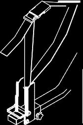
6 Follow the assembly procedure in order of A-B FREE STANDING RACK Assembly Step Check carton for following parts that are needed to complete Step of your Free Standing Rack Part Name Suspension Bar Locking Pin Qty 8 Suspension Bar A Pivot Arm B Locking Pin Locking Pin Tighten Knob to keep Pivot Bracket locked to Suspension Bar NOTES: Do not insert locking pin in to Pivot Arm at this time. It is inserted once a boat is in place. The location of the Suspension Bars is based on the width of your boats. See picture in Adjustment Instructions, adjustment 3. Page 5 suspenz.com
 Qty 6 1/ x Phillips Head Screw A Wall Mount Bracket C 1/ Flat Washer Suspension Bar Locking Pin Pivot Arm B")
7 Follow the assembly procedure in order of A-B-C WALL MOUNT RACK Assembly Check carton for following parts that are needed to complete assembly of your Wall Mount Rack Part Name Wall Mount Bracket 1/ x Phillips Head Screw 1/ Flat Washer Suspension Bar Locking Pin Extension Strap (not shown) Qty 6 1/ x Phillips Head Screw A Wall Mount Bracket C 1/ Flat Washer Suspension Bar Locking Pin Pivot Arm B Tighten Knob to keep Pivot Bracket locked to Suspension Bar Locking Pin CAUTION: Make sure that Wall Mount Bracket is screwed into a stud. Screwing only into drywall is not sufficient NOTES: The horizontal distance between the wall mounts should be 0% to 50% of the length of the boat. (SEE CHART on page 8). Do not insert locking pin into Pivot Arm at this time. It is inserted once a boat is in place. suspenz.com Page 6

 Qty 1 Square Plug from Floor Rack Post B")


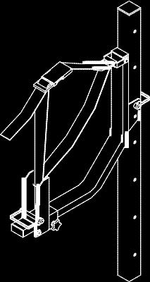
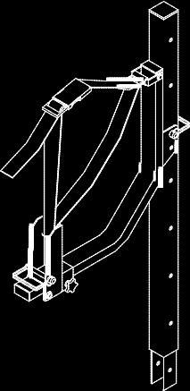
8 EXPANSION RACK Assembly Follow the assembly procedure in order of A-B-C Check carton for following parts that are needed to complete assembly of your Expansion Rack Part Name Post 5/16 Washer 5/16 Lock Washer 5/16 x 1 Hex Bolt Suspension Bar Locking Pin 1/ Hex Wrench Extension Strap (not shown) Qty 1 Square Plug from Floor Rack Post B Locking Pin C NOTES: Do not insert locking pin into the Pivot Arm at this time. It is inserted once a boat is in place. Remove the Square Plug from the Floor Rack and insert into Post. Suspension Bar Tighten Knob to keep Pivot Bracket locked to Suspension Bar Locking Pin Page 7 5/16 Lock Washer 5/16 x 1 Hex Bolt A 5/16 Washer suspenz.com

9 min. / max min. / 3 max min. / 6 max min. / 9 max min. / 5 max min. / 5 3 max min. / 5 6 max min. / 5 9 max 1 10 min. / 6 max min. / 6 3 max min. / 6 6 max min. / 6 9 max min. / 7 max min. / 7 3 max min. / 7 6 max min. / 7 9 max min. / 8 max min. / 8 3 max min. / min. / 8 9 max min. / 9 max min. / 9 3 max min. / 9 6 max min. / 9 9 max min. / 10 max min. / 10 3 max min. / 10 6 max min. / 10 9 max min. / 11 max min. / 11 3 max RACK ADJUSTMENT Instructions for All Boats 3 sets of adjustments are needed based on the length, width and depth of your boats: A. LENGTH: The length of your longest boat will determine the tower (or wall mount) spacing. B. WIDTH: The width of each boat defines where the suspension bar is placed on the post. C. DEPTH: The depth of each boat defines the position of the pivot arm and the length of the straps that your boat is suspended on. For WALL MOUNT RACKS skip adjustment. Boat Length Tower/Wall Mount Brackets Suspenz SPACING GUIDELINES Ideal Tower (or wall mount bracket) Spacing (0%) The min/max spacing for each kayak (35% / 50%) suspenz.com Page 8 3 Simple Adjustments to fit your kayak: 1.) Boat Width: vertical position of the suspension bar.) Boat Depth: pivot arm & strap adjustment 3.) Boat Length: distance between center of towers A.) Adjustments based on boat LENGTH: Adjustment 1: Tower (or wall mount) Spacing: Measure the length of your kayak. Position the towers (or wall mounts) so the length and weight of the boat are balanced equally on the suspension straps, meaning the distance between them is ~0% of the length of kayak. Example: If your kayak is 16 (19 ) long, the center of the towers should be 77 apart. (19 x. = 77 / 6 5 ) Here is a spacing guide line chart to help you decide what will work best for you. Adjustment : Level the Towers a) Eliminate Rocking: Rotate the leveling feet by hand so that all four feet make contact with the floor. It is important that the base does not rock. b) Side - Side Leveling: If post is not vertical adjust both feet on one side of the base to make the post vertical (this is a good time to use the level). c) Fore Aft Leveling: Rotate the two front feet by a similar amount so that the post is vertical or has a slight backward lean (this is a good time to use the level). The post should not lean forward in the unloaded state. It is normal for the posts to tilt slightly forward when boats are loaded.
 goes through the lower hole of the Suspension Bar (10) and the center hole of the base post (). C.")
 NOTE: Place the widest boat on the bottom rack position.")

10 B.) Adjustments based on boat WIDTH: Adjustment 3: Set the height of the lowest Suspension Bar The lowest height for the bottom Suspension Bar is shown. The Locking Pin (11) goes through the lower hole of the Suspension Bar (10) and the center hole of the base post (). C.) Adjustments based on boat DEPTH: We suggest starting at this lowest position if one of the boats is wide (> 30 inches). If all of your boats are narrow, you can start with a higher bottom position. The next suspension bar position should leave a -6 gap above the lower boat. (See Adjustment 8) NOTE: Place the widest boat on the bottom rack position. (this maximizes rack stability) Adjustment : Set the position of the Pivot Arm Boats can vary greatly in their cross section. The next two adjustments are starting point adjustments that work well for an average boat. You may need to fine tune them once your boat is in place. Once the Pivot Arms and straps are adjusted, they will not need to be adjusted again for the same boats. You will need to determine the depth of your boat at its suspension points. Lay your boat flat on the ground centered in front of the towers as if you were getting ready to place it in the rack. Now measure the depth of the boat at the points that line up with each tower. Write down these depths. Adjust the Pivot Arm distance on each Suspension Bar so that it equals the depth of the boat + 1/ inches. Tighten knob to lock pivot bracket in place. NOTE: If knob doesn t tighten completely then unscrew knob and add a washer. Caution: Do not exceed 18½ inches for the Pivot Arm Distance so that locking pin will engage. Adjustment 5: Set the Strap Length Adjust the length of the support strap so that the Pivot Arm lays horizontal when the strap is tight, as show. NOTE: Pivot arm should fall freely, If not, loosen hex bolt and nut (item 8 & 1) with hex wrench. Page 9 suspenz.com

.")
11 Adjustment 6: Verify Adjustments and Fine Tune Since boats can vary greatly in their cross section, you may need to fine tune adjustments & 5. Set Pivot Arms in their horizontal (open) position. Place the boat in the rack to assess the fit. If you have not yet opened your cold beverage, this would be an appropriate time to do so. a) Pivot arms are adjusted to suspend boat on its side so it is nearly at right-angle to the floor (be sure to tighten knob when adjusting Pivot arms). Top of boat should lean slightly toward back of rack when on its side (this prevents the boat from falling forward). There should be a small gap between the top of the pivot arm and the boat such that the pivot arm does not touch the boat. b) There should be a gap of about 1- inches between the boat and the suspension bar. Adjust the length of the strap to achieve this. Caution: The boat should be removed before adjusting the strap length (strap length is adjusted at the pivot arm). suspenz.com Page 10


12 Adjustment 7: Adjust Safety Strap and Add Extension Strap if Needed Verify that the safety strap can be connected over the top of the boat. For some larger boats, you will need to add the Extension Strap to have enough length. Adjust the safety strap length to achieve a snug fit. Adjustment 8: Configure For the Next Boat Add the Suspension Bars for the next boat then repeat adjustments 7 for this boat. Repeat again if you are using the Expansion Rack to hold 3 boats. Next Suspension Bar Position: Position the next set of Suspension Bars to leave a small gap ( - 6 inches) above the boat below. Page 11 suspenz.com


13 To load USE INSTRUCTIONS Open pivot arms (horizontal) toward front of rack, this will give more clearance for boat and ease loading. Center boat so same amount of the boat is suspended beyond each end of straps. When boat is positioned on its side and lowered onto straps, the Pivot arms will snap up into vertical position The Magic Moment! Adjust angle of boat to a secure resting position, fasten safety straps. NOTE: top side of boat should lean slightly toward back of rack when boat is on its side. This prevents the boat from falling forward. Insert locking pin into pivot arm to lock it in the closed position. Important: This is a safety requirment to prevent pivot arms from opening unintentionally. To unload Remove locking Pin (place locking pin in an empty post hole for safe storage) Release safety straps, lift boat slightly and move toward front of rack. You do not need to lift your boat over the pivot arms, they will fall forward automatically when weight of boat has been lifted. suspenz.com Page 1


 or re-locate racks if")


14 SAFETY REVIEW Allow enough time to set up racks properly. Make sure hardware is securely tightened. Install racks on a level surface. Once racks are set up, check for stability, secure (adjustment ) or re-locate racks if necessary. Anchors on leveling feet should be secured with a screw (not supplied) to floor if additional stability is needed. This is a requirement if on a dock. Be sure to fasten safety straps and insert locking pins in pivot arms when storing boats. STRAP THREADING The strap will be threaded through the pivot arm when received however, if you need to rethread it follow these instructions:: Step 1 Step Step Step 5 Step 3 Step 6 Page 13 suspenz.com


15 Customize your Free-Standing Racks Add Any of These Parts Back Legs Expansion Posts Cross Bar 6-Boat Racks Casters EZ Racks SUP Racks (1 or ) Canoe Flat Racks See our selection of Portable Boat Stands and Kayak & Canoe Carts Smart SK Cart & 33 Portable Boat Stands Smart DLX Cart Smart Sit-On-Top Cart suspenz.com Page 1
16 Marine Grade Back Legs SKU -001 To be used with Marine Grade Free-Standing Racks Updated October 011 Example of Back Leg in use. Tools Required: 1. Adjustable Wrench Item # Parts List Qty 1 3 Black Back Leg Leveling Foot Anchor Hex Jam Nut 8 Assembly: 1. Remove the carriage bolts, washers & lock nuts from original Free-Standing Floor Base & Base Post.. Line up Back Leg to Free-Standing Floor Base; attach Back Leg using the original hardware. NOTE: When putting attachments on the back-side of the rack, they should not extend more than. Currently the SUP Racks, EZ Racks and Marine Grade Deluxe Racks will work well on the backside. Cross-Bar is required when casters are used. Guarantee All Suspenz products are guaranteed for one year for materials and workmanship. The guarantee is affective to the original owner and if the product was cared for and used in the manner it was intended. Contact Suspenz directly with any questions.
SERIES 2 RAMP OWNER S MANUAL TOOLS REQUIRED: BEFORE YOU BEGIN... Read and understand these instructions before beginning a ramp setup.
 SERIES 2 RAMP OWNER S MANUAL BEFORE YOU BEGIN... Read and understand these instructions before beginning a ramp setup. Use caution and care for your back when lifting, pushing, pulling, folding or unfolding
U.S. Patent No. 7,922,246. Patents Pending
 U.S. Patent No. 7,922,246 Patents Pending 2 Table of Contents Page General Information... 3 Warnings and Cautions... 4 Tools... 6 SmartDock Parts... 6 Initial Set-Up and Adjustment... 7 Select Valve Retaining
8MAY15 US RACK, Inc Falcon Drive, Madera, CA
 8MAY15 US RACK, Inc. - 2850 Falcon Drive, Madera, CA 93637-559-661-3050 INSTRUCTIONS for Bedrail-mounted MOTORCYCLE RACK, Model 2001-4TRA WARNING: Do NOT attempt to install or use this rack without following
Side-of-Pole Mount for 1 Module (SPM1) For Module Types A & B
 For Module Types A & B") Side-of-Pole Mount for 1 Module (SPM1) For Module Types A & B ASSEMBLY INSTRUCTIONS step-by-step assembly and installation Version 1, Rev A PCN 080311-2 SP3363-1 Side-of-Pole Mount for 1 Module (SPM1)
Side-of-Pole Mount for 1 Module (SPM1) For Module Types A & B ASSEMBLY INSTRUCTIONS step-by-step assembly and installation Version 1, Rev A PCN 080311-2 SP3363-1 Side-of-Pole Mount for 1 Module (SPM1)
Important Note: Tighten lock nuts so the support tubes still swing freely see figure 2. There must be 1 2 threads of bolt past end of lock nuts.
 Kit Contents: DESCRIPTION QTY. DESCRIPTION QTY. 2 Shank Assembly 1 Support Tube Assembly 1 Side Tube - Short 2 1-1/4 Shank 1 Center Tube - Long 1 3/8-16 x 2.0 Carriage Bolt 2 5/16-18 x 2.25 Carriage Bolt
Thank you for purchasing a Porta-Dock product! *Please read and follow these instructions step by step*
 PG 1 OF 9 PORTA-DOCK, INC. 74A ABL/APW 1056 & 44A FLB APW 1056 PORTA-LIFT Thank you for purchasing a Porta-Dock product! *Please read and follow these instructions step by step* STEP 1. Separate and group
2,500/4,000 LB Easy Riser Vertical Cable Feighner Lift
 2,500/4,000 LB Easy Riser Vertical Cable Feighner Lift CAUTION - PUT SAFETY FIRST 1. Before attempting to install or operate this lift, study and fully understand the proper operating procedures and safety
QUALITY ALUMINUM BOAT LIFTS, INC. INSTRUCTIONS. Dominator Lake Lift
 INSTRUCTIONS Dominator Lake Lift PHONE:251-986-3882 * FAX:251-986-3136 QABLDOMINATORINST.2014 P a g e 1 Quality Aluminum Boat Lifts, INC. Installation Instructions: Dominator Lake Lift Thank you for your
OWNERS MANUAL. Model Shown with optional Primary Mooring Cleats. Portable Mooring System SAFETY OPERATION MAINTENANCE PARTS
 OWNERS MANUAL Model 2400 Shown with optional Primary Mooring Cleats. Portable Mooring System SAFETY OPERATION MAINTENANCE PARTS CAUTION: Before using your new Pier Tender, read rules for Safety, Operation,
Nautique Triton Clamping Board Rack V2
 w w w.ro swe l l marine.co m Nautique Triton Clamping Board Rack V2 Installation & Usage Instructions Part # C917-180045 Information: info@roswellmarine.com If you have any questions please call : 1-21-68-11
Shoreline Cantilever Lift 2500lb Capacity Models: (108" inside width) - Part # (120" inside width) - Part #
 - Part # (120 inside width) - Part #") Shoreline Cantilever Lift 2500lb Capacity Models: 25108 (108" inside width) - Part # 1017402 25120 (120" inside width) - Part # 1017403 1. 2. 3. 4. 5. CAUTION - PUT SAFETY FIRST Before attempting to install
Shoreline Cantilever Lift 2500lb Capacity Models: 25108 (108" inside width) - Part # 1017402 25120 (120" inside width) - Part # 1017403 1. 2. 3. 4. 5. CAUTION - PUT SAFETY FIRST Before attempting to install
VERSA BIKE RACK INSTRUCTIONS
 VERSA BIKE RACK INSTRUCTIONS Models #8, 8 Important This rack is designed for use with a or. receiver hitch. The rack is designed to hold a maximum of two bicycles. Do not use it for anything other than
#59114 Rola 2-Bike Rack Carrier (Shown Assembled) (A) (C) (B)
 (A) (C) (B)") Use for Parts: #59114 Rola -Bike Rack System #59115 Rola 1-Bike Add-On TOOLS REQUIRED 10mm or 13/3 Socket & Wrench #59114 Rola -Bike Rack Carrier (Shown Assembled) Tray Attachment Hardware: (3) Plastic
Use for Parts: #59114 Rola -Bike Rack System #59115 Rola 1-Bike Add-On TOOLS REQUIRED 10mm or 13/3 Socket & Wrench #59114 Rola -Bike Rack Carrier (Shown Assembled) Tray Attachment Hardware: (3) Plastic
C - SERIES. Height Adjustable Portable Goal Supports. Installation & Owner s Instructions C1000 C2000. Made in the USA
 C - SERIES Height Adjustable Portable Goal Supports C1000 C2000 Installation & Owner s Instructions Made in the USA This manual explains the proper installation, operation, and maintenance of your Schutt
Parts: Included in the parts box: Inner Rear Tire Tray. Inner Front Tire Tray. Trail Doc Clamp. Pivot Assembly. Trail Doc Post.
 NV 2.0 2 Parts: Outer Front Tire Tray Inner Front Tire Tray Outer Rear Tire Tray Inner Rear Tire Tray Pivot Assembly Trail Doc Clamp Trail Doc Post Included in the parts box: 6mm Allen Wrench M6 Lock Washer
Cover EX Installation Instructions
 Cover EX Installation Instructions 1. Lay out all the parts and verify that they are all present according to the Cover EX Parts and Hardware List. See Fig 1. Call 800-730-7727 for all replacement and
RADROVER REAR RACK INSTALLATION MANUAL
 RADROVER REAR RACK INSTALLATION MANUAL WWW.RADPOWERBIKES.COM We are here to help! Please contact us at SUPPORT@RADPOWERBIKES.COM or 1-800-939-0310 if you have questions. REV022216 Welcome Thanks you for
Assembly Instructions. -Cantilever Boat Lifts
 Assembly Instructions -Cantilever Boat Lifts Winch Instruction Page Safety Information 1. The winch is built for the multipurpose of hauling and lifting operations. It is not to be used as a hoist for
Big Ride ASSEMBLY AND INSTALLATION INSTRUCTIONS * * C A U T I O N * *
 Big Ride ASSEMBLY AND INSTALLATION INSTRUCTIONS * * C A U T I O N * * S.R. SMITH BIG RIDE SLIDES ARE MANUFACTURED FOR INSTALLATION AND USE ON INGROUND SWIMMING POOLS ONLY. THE BIG RIDE IS NEVER TO BE INSTALLED
Page 1. Single Scull Car Rack Assembly and User s Manual " "
 Page 1 Single Scull Car Rack Assembly and User s Manual Page 2 Items in the box: (2) V cradles (2) 4 rails (1) 1 3/4 X 18 rail coupler (4) 1/4-20 X 4 1/2 bolts (2) 1/4-20 X 2 1/2 bolts (12) 1/4 flat washers
STYRIGGER PRODUCT MANUAL
 STYRIGGER PRODUCT MANUAL Thank you for choosing the Styrigger kayak and canoe stabilizer. A kayak or canoe equipped with a Styrigger (safety outrigger) is an excellent choice for a beginner or someone
222 Schwinn Recumbent Exercise Bike Parts List Full Size Hardware Chart Product Illustration Assembly Instructions
 222 Schwinn Recumbent Exercise Bike Parts List Full Size Hardware Chart Product Illustration Assembly Instructions FITNESS SAFEGUARDS AND WARNINGS Before starting any exercise program, consult with your
FOLD AND ROLL PLAYBACK TABLE TENNIS TABLE
 OWNER'S MANUAL FOLD AND ROLL PLAYBACK TABLE TENNIS TABLE MODEL NOs. T8268 T8168 Thank you for buying our product. We try hard to ensure that our products are of high quality and free of problems, such
GENUINE PARTS INSTALLATION INSTRUCTIONS
 GENUINE PARTS INSTALLATION INSTRUCTIONS DESCRIPTION: APPLICATION: PART NUMBER: Weight Distributing Hitch Ball Mount Class IV See dealer application charts 999T7 WQ820 TOOLS REQUIRED: 14 mm Wrench or Ratchet
FIRST TEAM SPORTS, INC Storm Portable Series Assembly Instructions
 FIRST TEAM SPORTS, INC Storm Portable Series Assembly Instructions WARNING! WARNING! WARNING! THIS BASKETBALL SYSTEM IS SPRING LOADED AND SHIPPED UNDER TENSION. ATTEMPTING TO ASSEMBLE OR DISASSEMBLE ANY
VERTICAL SURFBOARD CARRIER READ ME! IMPORTANT WARNING!
 VERTICAL SURFBOARD CARRIER ENG RRAC09 30 min READ ME! Thank you for purchasing a Front Runner Vertical Surfboard Carrier. Before you start, take a moment to familiarize yourself with this Fitting Instruction
FOLD AND ROLL PLAYBACK TABLE TENNIS TABLE
 OWNER'S MANUAL FOLD AND ROLL PLAYBACK TABLE TENNIS TABLE MODEL NOs. T8269 T8169 Thank you for buying our product. We try hard to ensure that our products are of high quality and free of problems, such
USER S MANUAL QUESTIONS? CAUTION. Model No. FMEX Serial No. Write the serial number in the space above for reference. Serial Number Decal
 Model No. FMEX81110.0 Serial No. Write the serial number in the space above for reference. USER S MANUAL Serial Number Decal QUESTIONS? If you have questions, or if parts are damaged or missing, please
LITERIDER 2&3 IMPORTANT WARNING. 2Bike (1x) Bolt (1x) Nut (1x) Small Hex Wrench (1x)
 Bolt (1x) Nut (1x) Small Hex Wrench (1x)") LITERIDER 2&3 3 Bike (1x) Bolt (1x) Flat Washer (2x) Nut (1x) Large Hex Wrench (1x) 2Bike (1x) wrench (1x) Small Hex Wrench (1x) keys (2x) Long Strap (1x) 2-Zip Strips (6x) 3-Zip Strips (9x) Wheel strap
LITERIDER 2&3 3 Bike (1x) Bolt (1x) Flat Washer (2x) Nut (1x) Large Hex Wrench (1x) 2Bike (1x) wrench (1x) Small Hex Wrench (1x) keys (2x) Long Strap (1x) 2-Zip Strips (6x) 3-Zip Strips (9x) Wheel strap
Import Bike Rack OEM INSTALLATION MANUAL
 Import ike Rack OEM INSTLLTION MNUL TLE OF ONTENTS System Information 2 Safety Information 2 Resources Required 3 Preparation 3 Under umper ttachment 3 Over umper ttachment 3 Installation 3 Under umper
Sunset Swings By Health in Motion, LLC
 Sunset Swings By Health in Motion, LLC Model 421 Lounge Swing Assembly and Operation Manual Record Serial Number Here www.sunsetswings.com by Health In Motion, LLC. 1/30/2013 Caution: READ! VERY IMPORTANT
GRAVITY BIKE RACK ASSEMBLY & OPERATING INSTRUCTIONS
 GRAVITY BIKE RACK 94479 ASSEMBLY & OPERATING INSTRUCTIONS Due to continuing improvement, actual product may differ slightly from the product described herein. 3491 Mission Oaks Blvd., Camarillo, CA 93011
HoldUp Plus2. Safety Kit included: See additional instructions for installation. REAR WHEEL TRAY. BASE (1x) lock WASHER (1x) KEY (2x) SAFETY CLIP (1x)
 lock WASHER (1x) KEY (2x) SAFETY CLIP (1x)") HoldUp Plus2 InsTAll This product on 2" hitch version of the HoldUp Front WHEEL TRAY assembly (1x) REAR WHEEL TRAY assembly (1x) wrench (1x) BASE (1x) bolt (8X) Lock WASHER (8X) Washer (8x) KEY (2x) SAFETY
HoldUp Plus2 InsTAll This product on 2" hitch version of the HoldUp Front WHEEL TRAY assembly (1x) REAR WHEEL TRAY assembly (1x) wrench (1x) BASE (1x) bolt (8X) Lock WASHER (8X) Washer (8x) KEY (2x) SAFETY
VL SHEAVES/CABLE UPGRADE KIT INSTRUCTIONS
 VL SHEAVES/CABLE UPGRADE KIT INSTRUCTIONS RGC MARINE PRODUCTS BUFFALO, NY P/N 6112062 02/03/17 TABLE OF CONTENTS CHAPTER TITLE PAGE 1 SAFETY... 1 1.1 Introduction... 1 1.2 Safety Definitions... 1 1.3 Equipment
Duo/Trio Office Bike Owner s Manual
 Duo/Trio Office Bike Owner s Manual Welcome Congratulations on choosing to enhance your productivity and wellness with LifeSpan. You ve made a healthy decision, as the need for increased amounts of daily
READ ALL INSTRUCTIONS AND WARNINGS BEFORE USING THIS PRODUCT.
 Drywall Stills DS1830 Max Weight Capacity 225 Lb READ ALL INSTRUCTIONS AND WARNINGS BEFORE USING THIS PRODUCT. This manual provides important information on proper operation & maintenance. Every effort
MAVERICK FOOSBALL TABLE
 MAVERICK FOOSBALL TABLE Replacement Parts Order direct at or call our Customer Service department at (800) 225-7593 8 am to 5 pm Central Standard Time July 2010 UPC Code 7-19265-53446-4 Staple your receipt
SASK-A-POLE OWNERS AND USERS MANUAL
 SASK-A-POLE OWNERS AND USERS MANUAL GENERAL INFORMATION The Saskatchewan Abilities Council s Sask-a-Pole accessibility and transfer aid is designed to help provide safe and easy access to chairs, beds,
VL 2K LIFT D-L WINCH INSTRUCTIONS (Applies to P/Ns , , , , , )
") VL 2K LIFT D-L WINCH INSTRUCTIONS (Applies to P/Ns 3714022, 3714028, 3714034, 3714040, 3714043, 3714046) REIMANN & GEORGER CORPORATION MARINE PRODUCTS BUFFALO, NY P/N 6112103 04/09/18 1 SAFETY 1.1 INTRODUCTION
VL 2K LIFT D-L WINCH INSTRUCTIONS (Applies to P/Ns 3714022, 3714028, 3714034, 3714040, 3714043, 3714046) REIMANN & GEORGER CORPORATION MARINE PRODUCTS BUFFALO, NY P/N 6112103 04/09/18 1 SAFETY 1.1 INTRODUCTION
Side-of-Pole Mount for 1 Module (SPM1) For Module Type C
 For Module Type C") Module Type Width Length C 22-27 56-63 Side-of-Pole Mount for 1 Module (SPM1) For Module Type C ASSEMBLY INSTRUCTIONS step-by-step assembly and installation Version 1, Rev A PCN 022212-1 Side-of-Pole Mount
Module Type Width Length C 22-27 56-63 Side-of-Pole Mount for 1 Module (SPM1) For Module Type C ASSEMBLY INSTRUCTIONS step-by-step assembly and installation Version 1, Rev A PCN 022212-1 Side-of-Pole Mount
SAVE THESE INSTRUCTIONS DEALER/INSTALLER: GIVE TO HOMEOWNER OCEAN BLUE ABOVE GROUND POOL LADDERS
 SAVE THESE INSTRUCTIONS DEALER/INSTALLER: GIVE TO HOMEOWNER OCEAN BLUE ABOVE GROUND POOL LADDERS ASSEMBLY AND INSTALLATION MANUAL FOR A-FRAME AND INPOOL LADDERS A-FRAME Part No. 400100 PROUDLY MADE IN
Assembly Instructions & Manual. Configuration subject to change
 Assembly Instructions & Manual Configuration subject to change O R Y X II A S S E M B L Y I N S T R U C T I O N S & M A N U A L IMPORTANT PRECAUTIONS WARNING: To reduce the risk of serious injury, read
Caliber Sled Wheels Assembly Instructions for PN and 13579
 Caliber Sled Wheels Assembly Instructions for PN 13576 and 13579 Caution: Read all instructions before assembling or using Sled Wheels. Follow the steps in order. Only use Sled Wheels as intended, following
Specifications Testing & Adjusting Disassembly & Assembly
 SB4191E00 Jul. 2005 Specifications Testing & Adjusting Supplement for Quad Lift Mast D20/25/30/32/33S-3 G/GC20/25/30/32P-3 G/GC20/25/30/32E-3 Important Safety Information Most accidents involving product
Owner s Manual Tourmaster Storage Cart
 Owner s Manual Tourmaster CONTENTS Warranty.................................................................................2 Precautions.............................................................................2
Design Based Anchoring 2009 FORD F-150
 Design Based Anchoring OWNERS MANUAL USERS MANUAL 2008 Chief Automotive Technologies. CHIEF'S LIMITED ONE-YEAR WARRANTY & LIABILITY Chief Automotive Technologies warrants for one year from date of installation
USER MANUAL
 C Cimarron Sports 1-888-816-6517 www.cimarronsports.com Combo Pitching Machine USER MANUAL TABLE OF CONTENTS Thank you for purchasing the Cimarron Combo Pitching Machine. The Cimarron Combo Pitching Machine
Lock-N-Load. Bullet Feeder
 Lock-N-Load Bullet Feeder table of contents steps Overview... 2 List of required hand tools... 2 1: Mounting the Bullet Feeder to the Bench... 3 2: Mounting the Bullet Feed Hopper... 4 3: Bullet Feed Hopper
Installation/User s Guide Guide de l Utilisateur Installations- /Gebrauchsanleitung. U.S. Patent No. 7,922,246. Patent Pending
 Installation/User s Guide Guide de l Utilisateur Installations- /Gebrauchsanleitung For International Markets U.S. Patent No. 7,922,246 Patent Pending 2 Table of Contents Page General Information... 3
ALTERNATOR RACKS 135, 170 & 190 INSTRUCTIONS
 Figure A Item # Description Quantity 1 Alternator Rack 1 1 3 4 11 5 10 8 2 Lower Mount Kit (see detail) 2 3 16mm M5 Swivel-Mount Bolt 2 4 M7 Washer 2 5 M6 Lock Nut 2 6 Lock Washer 2 7 Swivel Mount 2 8
Item # in1 Rotating Table. Inch BILLIARDS AIR HOCKEY TABLE TENNIS
 Item # 45-6066 3-in1 Rotating Table 3 BILLIARDS AIR HOCKEY TABLE TENNIS 84 Inch ! WARNING: Rotating game should be done under adult supervision. Rotating table may cause a pinching hazard for young children
Before you start! Is iwalk 2.0 right for you?
 Before you start! Is iwalk 2.0 right for you? Physical Abilities Requirements 1. Stair Test Before your injury, could you easily walk up and down stairs at normal speed, without using the hand rail? 2.
CAUTION - PUT SAFETY FIRST
 www.shoremaster.com DVS Vertical Lift (Double V Side): Frame ssembly Instructions. Models: 500DVS - 0ft Wide, 5000lb Capacity - Part #: 0079 600DVS - 0ft Wide, 6000lb Capacity - Part #: 0033.. 3.. 5. CUTION
Final Assembly Instructions Bikes with 16 Wheel Size
 Final Assembly Instructions Bikes with 16 Wheel Size Thank you for buying your new bicycle from L.L.Bean. Read these instructions carefully before beginning the final assembly. Prior to shipping, our expert
USER MANUAL. DM65 Manual Flush/Tilt Combo Mount
 USER MANUAL DM65 Manual Flush/Tilt Combo Mount 1 D1_1.11.11.indd 1 ! CAUTION When using this mounting system, basic precautions should be followed, including: Follow the entire installation/user s manual
Rhino-Rack 570, 580. Important Information
 Important: Please read these instructions carefully prior to installation. Please refer to your fitting instruction to ensure that the kayak carrier is installed in the correct locations. Check the contents
INSTALLATION INSTRUCTIONS FOR ROLLOVER PROTECTION SYSTEM (ROPS)
") INSTALLATION INSTRUCTIONS FOR ROLLOVER PROTECTION SYSTEM (ROPS) This manual contains assembly, operating, maintenance and safety instructions for your ROPS. Before Installing the ROPS or operating a machine
INSTALLATION INSTRUCTIONS FOR ROLLOVER PROTECTION SYSTEM (ROPS) This manual contains assembly, operating, maintenance and safety instructions for your ROPS. Before Installing the ROPS or operating a machine
INSTALLATION INSTRUCTIONS
 KIT CONTENTS: INSTALLATION INSTRUCTIONS PART NUMBER: DESCRIPTION: E361SXA302 roof MOUNT BICycle CARRIER SINGLE Short Carriage Bolt 1x Long Carriage Bolt 3x Over-Molded Wrench 1x Button Head Screw 2x Washer
09/17/2007 Copy VISIT THE LIFETIME WEB SITE:
 VISIT THE LIFETIME WEB SITE: WWW.LIFETIME.COM IF ASSISTANCE IS NEED, CALL OUR CUSTOMER SERVICE PARTMENT 1 (800) 242-3865 Ext. 1408 HOURS: 9:00 a.m. to 5:00 p.m. Monday through Friday (Mountain Standard
Bike Rack and Tire Carrier
 Bike Rack and Tire Carrier OWNER'S MANUAL Rev: 10.26.2017 Page 1 Bike Rack and Tire Carrier Owners Manual TABLE OF CONTENTS System 2 Description 2 Prior To Operation 3 Manual Slide-Out Bike Rack Operation
-- SGP (NOVA TEAM SQUARE)
") -- SGP-100 -- (NOVA TEAM SQUARE) Installation Instructions Call Jaypro Sports Equipment at 1-800-243-0533 during regular business hours for technical support. www.jaypro.com Rev-B Page 1 of 9 JAYPRO SPORTS
-- SGP-100 -- (NOVA TEAM SQUARE) Installation Instructions Call Jaypro Sports Equipment at 1-800-243-0533 during regular business hours for technical support. www.jaypro.com Rev-B Page 1 of 9 JAYPRO SPORTS
MAGNETIC INDOOR CYCLING BIKE
 MAGNETIC INDOOR CYCLING BIKE SF-B1805 USER MANUAL IMPORTANT! Please retain owner s manual for maintenance and adjustment instructions. Your satisfaction is very important to us, PLEASE DO NOT RETURN UNTIL
MASTER TRUING STAND TS-3. Optional Dial indicator set with brackets Dial indicator bracket set only
 MASTER TRUING STAND TS-3 3 2 1 3 8 9 4 10 7 6 5 12 13 Optional 1555-1 Dial indicator set with brackets 1556-1 Dial indicator bracket set only 49 11 16 14 15 48 32 31 37 38 20 19 17 18 34 39 21 36 22 33
Foos 300 Assembly Instructions
 Foos 300 Assembly Instructions Thank you for purchasing a Shelti product. All of us at Shelti want you to be completely satisfied with your Foos game, so feel free to contact us for help with the assembly
Assembly Guide ST200 FUNCTIONAL TRAINER
 Assembly Guide ST200 FUNCTIONAL TRAINER Assembly Guide ST200 FUNCTIONAL TRAINER To avoid possible damage to this Functional Trainer, please follow these assembly steps in the correct order. Before proceeding,
Universal Anchoring Adapter For Mercedes
 Universal Anchoring Adapter For Mercedes Anchoring Pin & Tube Set (For Most Mercedes Models) Users Manual 006 Chief Automotive Technologies, Inc. Chief s Limited One-Year Warranty & Liability CHIEF'S
Flying - J Rack. Model # SAFETY INFORMATION. Parts List. Part Name. Mounting Hardware. Bow & Stern Ropes. Flying -J Racks.
 Flying - J Rack Model # -013 Parts List Qty Mounting Hardware Flying -J Racks Part Name Flying-J Rack Tie Down Strap Bow & Stern Rope Metal Plate Bolt Knob Washer Bow & Stern Ropes Tie Down Straps SAFETY
600 / 600FC OWNER'S MANUAL
 PROGRESSION 600 / 600FC OWNER'S MANUAL Issue 2 / Version E - Dec. 10, 1997 Copyright 1997 GAMMA Sports - All Rights Reserved PROGRESSION 600 / 600FC OWNER'S MANUAL TABLE OF CONTENTS PAGE 1... WARRANTY
Assembly Instructions
 CS-B-FM Assembly Instructions Thank you for purchasing a Shelti product. All of us at Shelti want you to be completely satisfied with your Pro Foos game, so feel free to contact us for help with the assembly
STAND AID 1600/ ECONOSTAND
 MAKERS OF STAND AID, POWER TOILET AID AND FREEDOM CHAIR STAND AID 600/ ECONOSTAND INSTRUCTIONS AND WARRANTY FOR STAND AID 600 STAND AID SERIAL # PO BOX 386 Sheldon, IA 50 (800) 83-8580 (7) 34-53 Fax: (7)
SCOUT DECK ANCHOR 3 1/4" BONDING SCREW
 SCOUT DECK ANCHOR 16" 16" 1" X 4" ANCHOR BOLT (4) 10" 3 1/8" 5" 6" MIN COPPER WIRE TO ATTACH TO BONDING GRID 3 1/4" BONDING SCREW CONCRETE DECK SPECIFICATIONS: THE AQUA CREEK PRODUCTS' SCOUT DECK ANCHOR
Ladies Shopper Bike Assembly Manual 28C03
 Ladies Shopper Bike Assembly Manual 28C03 Ecosmo Ltd 1 Know your bike 1. Wheel 2. Rear Derailleur 3. Chain 4. Crank Set 5. Pedal 6. Seat Quick Lock 7. Saddle and Post 8. Frame 9. Front Light 10. Front
A A A
 Mossberg 0 GA Talon T Rear Pistol Grip with Scorpion Recoil System A.5.0.6 A.5.0.6 A.5.0.6 Extended Scorpion Material to Reduce and Discomfort to the Shooter's Hand and Thumb Sure-Grip Texture 70.0.0 Mossberg
COPY. **For U.S. and Canada Customers ONLY:** IF ASSISTANCE IS NEEDED,
 MODEL #73729 WARNING Failure to comply with any of the warnings in these instructions may result in serious personal injuries such as cuts, broken bones, nerve damage, paralysis, brain injury, or death.
BICYCLE TO MOTORCYCLE BICYCLE RACK
 BICYCLE TO MOTORCYCLE BICYCLE RACK Install Manual Warning: You are responsible for securing the rack to your motorcycle., checking the attachments prior to use and periodically inspecting the products
Backboard and Rim Owners Manual
 REQUIRED TOOLS AND MATERIALS: Two (2) Capable Adults Tape Measure Backboard and Rim Owners Manual Customer Service Center N53 W24700 South Corporate Circle Sussex, WI 53089 U.S.A. Step Ladder - 8ft. (2.4
Booster Pump PB4-60 Replacement Kits
 Booster Pump PB4-60 Replacement Kits FOR YOUR SAFETY - This product must be installed and serviced by a contractor who is licensed and qualified in pool equipment by the jurisdiction in which the product
IMPORTANT: RECEIVING INSTRUCTIONS:
 Instruction Sheet Sidewinder Mechanical Bender IMPORTANT: RECEIVING INSTRUCTIONS: Visually inspect all components for shipping damage. If any shipping damage is found, notify carrier at once.shipping damage
Installation Guide RHT-380. This Manual Must Be Read Before Operating The Equipment CUSTOMER COPY
 Installation Guide This Manual Must Be Read Before Operating The Equipment RHT-380 Madison Heights, Michigan 48071 800-725-8377 www.snowexproducts.com CUSTOMER COPY Trynex International 2013 (REV B) F50767
CENTER-STRUT HEIGHT ADJUSTMENT UNITS MANUAL OPERATION
 ASSEMBLY, INSTALLATION &MAINTENANCE INSTRUCTIONS CENTER-STRUT HEIGHT ADJUSTMENT UNITS MANUAL OPERATION No. 00900-211 and 00900-506 Nylon spacer (2) located between fan backboard support and backboard FAN
T-016 ASSEMBLY MANUAL MODEL ROCK AND ROLL Main Street NE Minneapolis, MN
 MODEL T-016 ASSEMBLY MANUAL ROCK AND ROLL 5280 Main Street NE Minneapolis, MN 55421 1.877.226.7824 www.kurtkinetic.com COMPONENTS Tools Required for Assembly: 17mm Wrench or Adjustable Wrench When unpacking,
MODEL SWH10 1,000 LB CAPACITY SWIVEL HOIST
 MODEL SWH10 1,000 LB CAPACITY SWIVEL HOIST PARTS BREAKDOWN AND OPERATING MANUAL Copyright 2007, Arcan Professional Tools Rev: 05/15/07 This operating manual contains important safety information. Read
CONFER IN-GROUND CURVE STEP / IN-GROUND CURVE STEP SYSTEM ASSEMBLY AND INSTALLATION MANUAL
 SAVE THESE INSTRUCTIONS DEALER/INSTALLER: GIVE TO HOMEOWNER CONFER IN-GROUND CURVE STEP / IN-GROUND CURVE STEP SYSTEM ASSEMBLY AND INSTALLATION MANUAL Model CCX-IG Note: 40 lbs. of sand required! SAND
FIX ROAD & FIX STRAP cargo securing systems Operating Instruction Manual
 FIX ROAD & FIX STRAP cargo securing systems Operating Instruction Manual NWE NETWORK ENGINEERING OY AB VAT: FI 09628099 1 Introduction Please ensure you read these instructions and understand them fully
A A A
 Winchester SXP Talon T Rear Pistol Grip with Scorpion Recoil Grip A.5.0.65 A.5.0.65 A.5.0.65 Extended Scorpion Material to Reduce and Discomfort to the Shooter's Hand and Thumb Sure-Grip Texture Triton
MODEL #7100X A-FRAME LADDER
 SAVE THESE INSTRUCTIONS DEALER/INSTALLER: GIVE TO HOMEOWNER MODEL #7100X A-FRAME LADDER LADDER MUST BE ATTACHED TO POOL FRAME... DO NOT USE WITH INFLATABLE POOLS ASSEMBLY AND INSTALLATION MANUAL The Anti-Entrapment
PHOENIX MMXI 7 FOOT 3 IN 1 BILLIARD TABLE
 Phoenix MMXI 3 in 1 Billiard Table PHOENIX MMXI 7 FOOT 3 IN 1 BILLIARD TABLE Replacement Parts Order direct at or call our Customer Service department at (800) 5-7593 ext. 113 8 am to 4:30 pm Central Standard
Side-of-Pole Mount for 1 Modules (SPM1) For Module Types E, F, G, & H ASSEMBLY INSTRUCTIONS. step-by-step assembly and installation
 For Module Types E, F, G, & H ASSEMBLY INSTRUCTIONS. step-by-step assembly and installation") Side-of-Pole Mount for 1 Modules (SPM1) For Module Types E, F, G, & H ASSEMBLY INSTRUCTIONS step-by-step assembly and installation Version 1, Rev A SP3348-1 PCN 022212-2 Side-of-Pole Mount for 1 Module
Side-of-Pole Mount for 1 Modules (SPM1) For Module Types E, F, G, & H ASSEMBLY INSTRUCTIONS step-by-step assembly and installation Version 1, Rev A SP3348-1 PCN 022212-2 Side-of-Pole Mount for 1 Module
Installation Manual. Version 12-10
 Installation Manual The products and parts shown herein are to be installed and used adjusted in accordance with these instructions. Any deviation by the buyer, installer, or user from these instructions
MODEL / SINGLE and DUPLEX PULLEY SYSTEMS
 MODEL 922181/922182 SINGLE and DUPLEX PULLEY SYSTEMS MODEL 922181 SINGLE PULLEY SYSTEM MODEL 922182 DUPLEX PULLEY SYSTEM 1 PARTS LIST FOR SINGLE/DUPLEX COLUMN PULLEYS Note: Check with your architect or
Tripod Setup Guide (M-TPx)
") Items needed: 1/2 inch wrench, mast level (M-MLA), medium size wire cutters, crescent wrench, all-purpose grease, tape measure, tie wraps, redi-mix cement (optional), shovel (optional), sledge hammer (for
Items needed: 1/2 inch wrench, mast level (M-MLA), medium size wire cutters, crescent wrench, all-purpose grease, tape measure, tie wraps, redi-mix cement (optional), shovel (optional), sledge hammer (for
310 SERIES TILT-TO-LOAD ROTATOR. The Specialist In Drum Handling Equipment
 OPERATOR S MANUAL FOR MORSE TILT-TO-LOAD DRUM ROTATOR SAFETY INFORMATION: While Morse Manufacturing Co. drum handling equipment is engineered for safety and efficiency, a high degree of responsibility
BELT DRIVE PREMIUM INDOOR CYCLING BIKE SF-B1509 USER MANUAL
 BELT DRIVE PREMIUM INDOOR CYCLING BIKE SF-B1509 USER MANUAL IMPORTANT! Read all instructions carefully before using this product. Retain owner s manual for future reference. For customer service, please
Gurney Flap for WRX and STI w/low Profile Trunk Spoiler
 Gurney Flap for 2015+ WRX and STI w/low Profile Trunk Spoiler 2017-12-05 Thank you for purchasing this PERRIN product for your car! Installation of this product should only be performed by persons experienced
OWNER'S MANUAL. Copyright 1999 ATS - All Rights Reserved
 OWNER'S MANUAL AL Issue 2 - August 19, 1999 Copyright 1999 ATS - All Rights Reserved OWNER'S MANUAL TABLE OF CONTENTS PAGE 1... WARRANTY PAGE 2... ASSEMBLY INSTRUCTIONS PAGE 4... MOUNTING THE RACQUET PAGE
Soccer Goal. Model: SG20 Series. Installation, Operation and Maintenance Instructions
 Soccer Goal Model: SG20 Series Installation, Operation and Maintenance Instructions Please read all instructions before attempting installation or operation of these units SAVE THESE INSTRUCTIONS FOR FUTURE
84 3-in-1 Rotating Table Air Powered Hockey, Billiards, Table Tennis
 Item# 45-6708 84 3-in-1 Rotating Table Air Powered Hockey, Billiards, Table Tennis Please keep this instruction manual for future reference If you have any problems with your new product, please contact
Confer Plastics Inc. - Installation Manuals CONFER PLASTICS, INC. CONFER PLASTICS, INC. POOL ENTRY SYSTEM FOR ABOVE-GROUND POOLS
 Page 1 of 6 Other Installation Manuals CONFER PLASTICS, INC. CONFER PLASTICS, INC. POOL ENTRY SYSTEM FOR ABOVE-GROUND POOLS Adjusts to fit most above-ground pools with flat or slightly dished bottoms PARTS
EXTERNALLY ROUTED DROPPER POST owner S MANUAL
 EXTERNALLY ROUTED DROPPER POST owner S MANUAL Introduction: This adjustable height seat post with internal cable routing allows for micro-adjustments using a remote handlebar mounted lever. The cable actuated
MODEL TRIPEX PULLEY SYSTEM
 MODEL 922184 TRIPEX PULLEY SYSTEM 1 PARTS LIST FOR TRIPEX PULLEY SYSTEM Note: Check with your architect or a professional contractor for hardware required to attach the unit to the wall and floor in your