CONSTRUCTOPEDIA NXT Kit 9797
|
|
|
- Justin McCarthy
- 6 years ago
- Views:
Transcription
1 CONSTRUCTOPEDIA NXT Kit 9797 Beta Version 2.0 August 17, 2007 Center for Engineering Educational Outreach Tufts University
2 Table of Contents Simple Shapes and Structures. Page 3 Ways To Attach NXT Motors... Page 6 Front End Setups.. Page Minute Building Projects. Page 51 Full Car Models.... Page 62
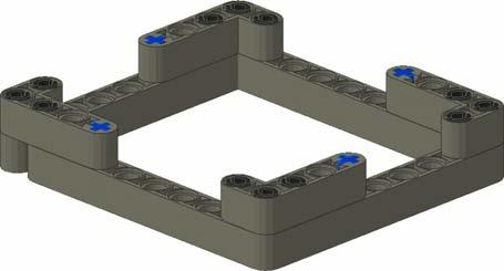

3 Building Instructions: Simple Shapes and Structures Simple Shapes and Structures Square Reversing Trick Cube
4 Building Instructions: Simple Shapes and Structures Arch Beams


5 Building Instructions: Simple Shapes and Structures Triangle Alternate Triangle

6 Building Instructions: Ways to Attach NXT Motors Simple Side Attachment Model Description: This is a motor attachment option in which the motors attach closely to the sides of the NXT.

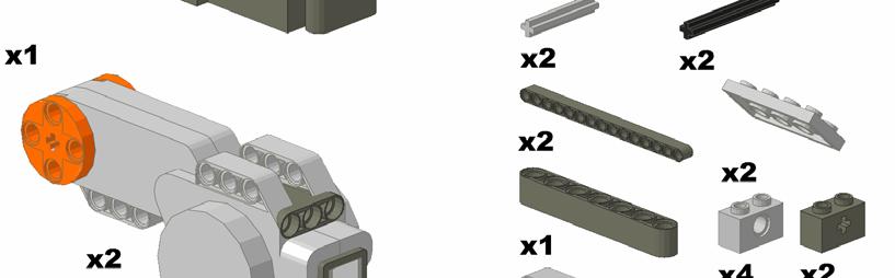
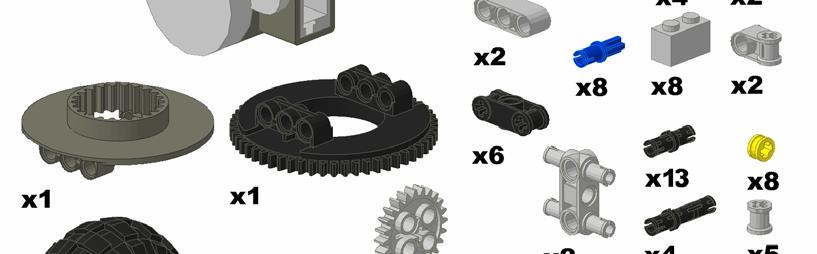
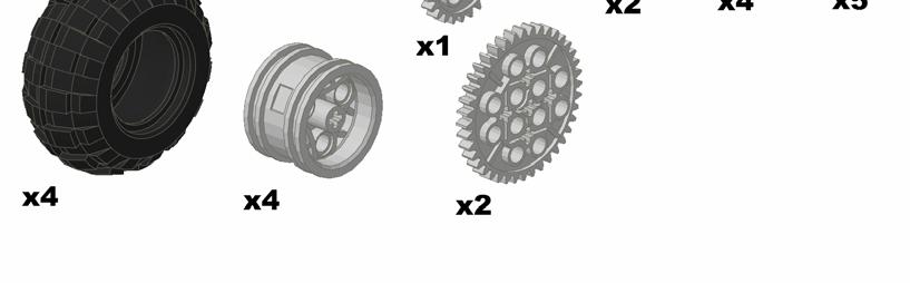
7 Building Instructions: Ways to Attach NXT Motors These are the parts that you will need:


8 Building Instructions: Ways to Attach NXT Motors Step# 1 Attach the two bent beams to the NXT using friction pins. The shorter portion of the beam should be sticking out from the NXT. Insert a double pin connector into this portion. Step# 2 Fasten the motors to the double pin connectors on the bent beams. Then fit a four pin axel joiner into the outside mounting beam on the NXT.

9 Building Instructions: Ways to Attach NXT Motors Step# 3 Attach the double bent beam to the four pin axel joiner and the NXT using the axel pins and friction pins.
10 Building Instructions: Ways to Attach NXT Motors Underside Motor Attachment Model Description: This is a simple, stable way to attach two motors under the NXT.

11 Building Instructions: Ways to Attach NXT Motors These are the parts that you will need:


12 Building Instructions: Ways to Attach NXT Motors Step# 1 Connect two grey axle joiners to the black axle joiner using two 2 stud axles. Connect the five hole beam to the gray axle joiners using a long friction pin. Then connect the beam to the motor using two more long friction pins. Repeat this process for the second motor. Step# 2 Attach each motor assembly to the bottom of the NXT by the black axle joiner, using a friction pin. Then secure each motor using the bent beam.

13 Building Instructions: Ways to Attach NXT Motors One Step Motor Attachment Model Description: This is a very simple way, using few pieces, to attach motors.


14 Building Instructions: Ways to Attach NXT Motors Step# 1 (and only) The left and right side are symmetrical.
15 Building Instructions: Ways to Attach NXT Motors Angled Back Attachment Model Description: This is a motor attachment option in which the motors angle downward from the NXT. (See Step #2 for side visual.)


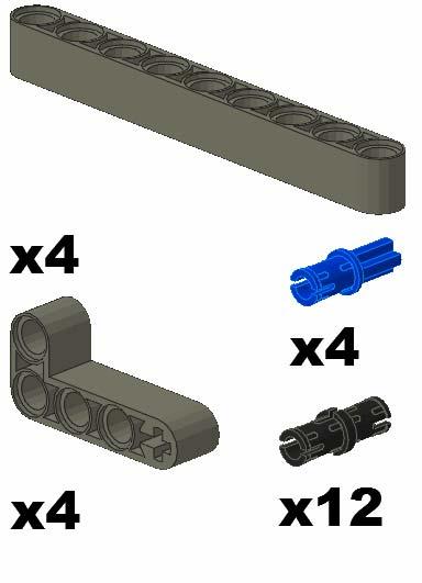
16 Building Instructions: Ways to Attach NXT Motors These are the parts that you will need:


17 Building Instructions: Ways to Attach NXT Motors Step# 1 Attach the two bent beams to the NXT using a friction pin and an axle pin on each. The shorter portion of the beam should be sticking out from the NXT. Step# 2 Fasten the motors to the bent beams using the extended pins. Make sure the bent beams are placed in between the two mounting beams on the NXT.


18 Building Instructions: Ways to Attach NXT Motors Step# 3 Slide the 12-axle through the mounting beams of the motor and secure it in place with ½ bushes. Use the friction pins to attach the 13-beam across the tops of the motors.
19 Building Instructions: Ways to Attach NXT Motors Sturdy Motor Attachment Model Description: This model is a compact, sturdy, way to attach NXT motors.


20 Building Instructions: Ways to Attach NXT Motors These are the parts that you will need:


21 Building Instructions: Ways to Attach NXT Motors Step# 1 Thread the two 12-axles through the NXT motors, beams, and bent beams. Step# 2 Attach 6 friction pins into the NXT. (3 per side)


22 Building Instructions: Ways to Attach NXT Motors Step# 3 Combine the parts from steps #1 and #2. Attach the bent beams to the friction pins in the NXT and to the axles from step #1. Use a half bush to hold the 3-5 bent beam to the axle. Both sides are symmetrical.


23 Building Instructions: Ways to Attach NXT Motors Wide Back Attachment Model Description: This is a motor attachment option in which the motors are mounted far apart in the back of the NXT.


24 Building Instructions: Ways to Attach NXT Motors These are the parts that you will need:


25 Building Instructions: Ways to Attach NXT Motors Step# 1 Attach the two bent beams with friction pins to the back of the NXT so that the shorter portion sticks out the back. Then, use the straight beams to attach those to a double pin connector inserted in the front of the NXT.


26 Building Instructions: Ways to Attach NXT Motors Step# 2 Place the double pin connector in the NXT slots and connect one of the double bent beams to it. Place two pins in the bent beams from step one and connect the other double bent beam to those, leaving one space from the single bent beam uncovered. Lastly, place the appropriate pins in the TOP SIDE of the end of the double bent beams. Step# 3 Attach four pin axle joiners to the NXT motors. Then, snap the four pin axle joiners onto the pins sticking up out of the double bent beams.


27 Building Instructions: Ways to Attach NXT Motors Step# 4 Attach the bent beams to the NXT holes with the friction pins. Have the large portion sticking out backwards. Insert two 8-axles and two 6-axels into the motors and NXT holes. Fasten the motors in place by placing bushes on the axles on both sides of the motor bars.
28 Building Instructions: Ways to Attach NXT Motors Compact Motor Attachment Model Description: This is a simple, compact way of attaching motors to the NXT.


29 Building Instructions: Ways to Attach NXT Motors These are the parts that you will need:


30 Building Instructions: Ways to Attach NXT Motors Step# 1 Replacing the 2 vertical beams with longer beams, and having those hang below the horizontal beam might be a good set up for a different build. Step# 2 In the diagram above, the right motor and beam is extended out, to provide an intermediary step.

31 Building Instructions: Ways to Attach NXT Motors Step# 3 Attach the part from step #1 to the part from step #2 so that the beams from the first step connect to the back of the motors.

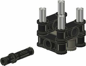
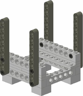
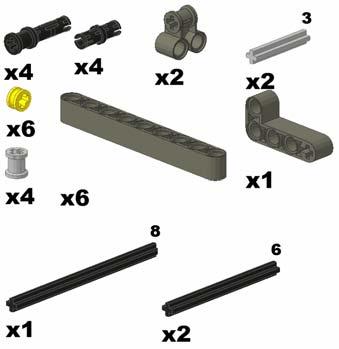
32 Building Instructions: Ways to Attach NXT Motors Vertical Motor Attachment Model Description: This is a motor attachment option in which two motors are held vertically


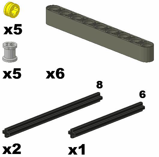
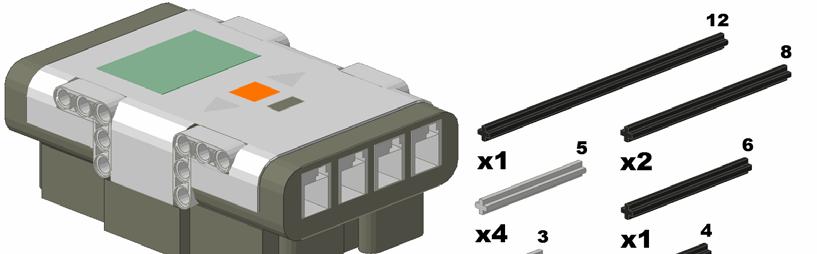
33 Building Instructions: Ways to Attach NXT Motors These are the parts that you will need:


34 Building Instructions: Ways to Attach NXT Motors Step# 1 Insert the two axles through the top two holes of the motors and the double axle joiners simultaneously. The double axle joiners should be in between the two axle holding bars on each motor. Secure the bars with the bushes. Step# 2 Attach the double axle joiners to the underside of the NXT using two axle pins.


35 Building Instructions: Ways to Attach NXT Motors Step# 3 Use two black pins to attach each of the two bent beams to the tops of the motors. Then place a black pin in the corner of each bent beam and an axle pin in the end. Step# 4 Link the bent beams from step three to the NXT using the axle pins and the two linking pieces. Push all the pieces completely down on the pins. Then, attach the straight beam to the top of the bent beams above the motors using the pins already placed in during step three.

36 Building Instructions: Front End Setups Swiveling Front Attachment Model Description: This is a front wheel attachment option in which one small wheel has the ability to swivel. This allows the car to turn easily.

37 Building Instructions: Front End Setups These are the parts that you will need:


38 Building Instructions: Front End Setups Step# 1 Attach one beam to the bottom of the NXT using two pins. Insert the double pin connectors into that beam. Then attach two more beams to those pieces using the other pins. Step# 2 Insert a 4-axle through the wheel and slide a perpendicular connector piece onto each side of it. Make sure the open hole is the part slid on so that the axle rotates. Secure them with ½ bushes. Stick a 4-axle through the axle part of each of the connector pieces and slide another connector piece (using the open hole section) onto each of those, separated by a bushing. Secure the ends of these axles with ½ bushes. Finally slide one more 4-axle through the two connector pieces and through the shaped end of one more perpendicular connector piece, so that it sticks straight backwards.

39 Building Instructions: Front End Setups Step# 3 Insert a 6-axle up through the bottom two beams and secure it with a bush in the open space. Slide a bush up the bottom of the axle, followed by the wheel setup, and then another ½ bush.
40 Building Instructions: Front End Setups Long Front Setup Model Description: This is a front end setup that can slide or hold another wheel.


41 Building Instructions: Front End Setups These are the parts that you will need:


42 Building Instructions: Front End Setups Step# 1 Connect the two black axle joiners to the 9-beam using the axle pins. Connect the two gray axle joiners to the 9-beam as well. Connect the 5-beam to the grey axle joiners using the connecting pins. Connect the 3-beams to the grey axle joiners. Step# 2 Connect the bent beams to the axle joiners using the 3-axles.

43 Building Instructions: Front End Setups Step# 3 Connect the lift arms from step #2 to step #1, and then connect that to the NXT.

44 Building Instructions: Front End Setups Sliding Front Attachment Model Description: This is a front wheel attachment option with skids to slide around on. This gives an NXT car the ability to turn without the use of a wheel.

45 Building Instructions: Front End Setups These are the parts that you will need:


46 Building Instructions: Front End Setups Step# 1 Attach the hole sections of the perpendicular connector pieces to the NXT using pins. Make sure the axle holes face horizontally. Insert a 4-axle into the perpendicular connector pieces and fasten it in place with two ½ bushes. Step# 2 Fasten two curved beams to a 7-beam using extended pins. This is the sliding piece.

47 Building Instructions: Front End Setups Step# 3 Take one of the ½ bushes off the axle and pull the axle out. Slide it back in, inserting it through the setup from step two. Replace the bush on the axle.

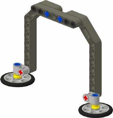
48 Building Instructions: Front End Setups Dual Wheel Setup Model Description: This is a front wheel attachment that has bars to hold various sensors.

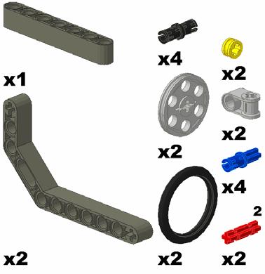
49 Building Instructions: Front End Setups These are the parts that you will need:


50 Building Instructions: Front End Setups Step# 1 Attach the 7-axle to the bent lift arm. Attach the axle joiner to the bottom of the axle, and place an axle pin inside the axle joiner. Attach a friction pin to the lift arm. Repeat for the second lift arm. Step# 2 Attach each axle assembly to the NXT and add wheels to the axle pins.

51 Building Instructions: 15 Minute Building Projects Swing Set Model Description: This is a swing set that can be programmed to move back and forth.

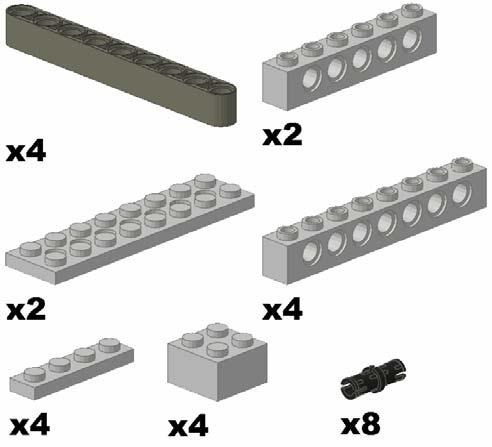
52 Building Instructions: 15 Minute Building Projects These are the parts that you will need:


53 Building Instructions: 15 Minute Building Projects Step# 1 Connect the two lift arms using two connector pins. Place a long pin with friction into the top holes of the lift arms. Connect these pins to the grey axle joiners. Insert a 6 stud axle into each axle joiner. Place a grey connector on each axle. Connect the black axle joiners using the 2 stud axles. Step# 2 Slide the 10 stud axles through the black axle joiners from the previous step, and connect them using the axle connector. Create the base by connecting the beams to the second and fourteenth hole of the studded beams using a pin and a long pin. Slide the 10 stud axles through the ends of the beams. Connect the 7-beam to the right side of the assembly in the 8 th hole from the bottom using a long and short pin. Place the 5 stud axle in the middle hole of the 7-beam, securing it on either side with the ½ bushings.


54 Building Instructions: 15 Minute Building Projects Step# 3 Place one of the 24 tooth gears on the exposed 10 stud axle at the top of the assembly. Connect the other 24 tooth gear using the axle pin to the 4 th hole from the top of the beam. Connect one of the 40 tooth gears to the 5 stud axle in the middle of the assembly. Connect the other 40 gear using the 3 stud axle to the motor.
55 Building Instructions: 15 Minute Building Projects NXT Merry-Go-Round! Model Description: This medium building difficulty merry-go-round can rotate forever!! Wires will never get tangled up since the NXT spins with the motors. This model uses LEGO rubber bands to help hold one of the motors in place.


56 Building Instructions: 15 Minute Building Projects These are the parts that you will need: **You will need two LEGO rubber bands (belts).


57 Building Instructions: 15 Minute Building Projects Step# 1 (do this step twice) Repeat step #1. Do not repeat it in a mirror image, you want two exact copies. Set them aside until step #5. Step# 2 Once the wheels are attached, the Merry-Go-Round will have a base.


58 Building Instructions: 15 Minute Building Projects Step# 3 Use the parts from step #2. The base is now complete. The NXT will slide onto the 4 friction pins sticking out in the above figure. Set aside until step #7. Step# 4 Slide the two 4-axles through the holes of the NXT motor and through the holes of the black 3 long perpendicular technic axle joiners. It is hard to see the 4-axles in the diagram above. Set aside until step #7.


59 Building Instructions: 15 Minute Building Projects Step# 5 Attach the ponies from step #1 to the motor using a 12-axle. Set aside until step #7. Step# 6

 to hold")
60 Building Instructions: 15 Minute Building Projects Step #7 Attach the NXT to the base, and attach the motors to the NXT. Step# 8 Use rubber bands (LEGO belts) to hold the motor in place.


61 Building Instructions: 15 Minute Building Projects Step #9 Your program must run both motors continuously. You will need to adjust the motor powers to obtain an appropriate speed. You may also need to adjust the placement of the rubber bands to ensure that the gears stay meshed. If you find the gears aren t staying together try rotating the motor the opposite direction so the force pushes it into the NXT instead of away.

62 Building Instructions: Full Car Models NXT Quick-Start Car Model Description: This is a simple, two-motor car that can be built in less than 15 minutes using the NXT kit. Additionally, all types of sensors can easily be added to this model.


63 Building Instructions: Full Car Models These are the parts that you will need:


64 Building Instructions: Full Car Models Step# 1 Attach 2 motors to the NXT using long friction pins and double friction pins. Step# 2 Attach 2 bent beams to the front of the car using the two pins. These beams will hold the front wheels.


 Attach the touch, proximity,")

65 Building Instructions: Full Car Models Step# 3 Attach 2 large NXT wheels to the motors using two 6-axels. Use the axel pins to secure the small wheels to the bent beams. Leave the front wheels bare to allow them to slide easily when the car is programmed to turn. Step# 4 (Optional Sensor Additions) Attach the touch, proximity, or sounds sensor to the top of one of the motors using the long friction pin. Attach the light sensor to one of the bent beams using the normal friction pins. The light sensor should be facing the ground.
QUALITY ALUMINUM BOAT LIFTS, INC. INSTRUCTIONS. Dominator Lake Lift
 INSTRUCTIONS Dominator Lake Lift PHONE:251-986-3882 * FAX:251-986-3136 QABLDOMINATORINST.2014 P a g e 1 Quality Aluminum Boat Lifts, INC. Installation Instructions: Dominator Lake Lift Thank you for your
SERIES 2 RAMP OWNER S MANUAL TOOLS REQUIRED: BEFORE YOU BEGIN... Read and understand these instructions before beginning a ramp setup.
 SERIES 2 RAMP OWNER S MANUAL BEFORE YOU BEGIN... Read and understand these instructions before beginning a ramp setup. Use caution and care for your back when lifting, pushing, pulling, folding or unfolding
The Rubber Band Car. Lesson Guide. The Challenge: To build a car that moves under the power of rubber bands! Topics: Forces, Energy, Simple Machines
 The Rubber Band Car The Challenge: To build a car that moves under the power of rubber bands! Topics: Forces, Energy, Simple Machines Version 1 Materials: 2 compact discs (per group) Corrugated cardboard
Trilogy Theory of Operation
 INSTALLATION & OVERVIEW... 2 Load Height... 2 Approach Angle... 2 Footprint... 3 Protrusion... 3 Mounting the... 4 General Torque Specs... 4 OPERATION OF BIKE RACK... 5 Loading Bikes... 5 Unloading Bikes...
E-trike Li Assembly Guide
 PREPARATION 1. Read this assembly manual BEFORE commencing assembly. 2. Carefully remove all the components and packaged hardware from the shipping boxes. 3. Unpack the contents of the large double box
Building a Wind Tunnel
 Technical Report TR-5 Building a Wind Tunnel Estes Industries 1963 These reports are published as a service to its customers by Estes Industries, Inc., Box 227, Penrose, Colorado 81240 Building a Wind
Caliber Sled Wheels Assembly Instructions for PN and 13579
 Caliber Sled Wheels Assembly Instructions for PN 13576 and 13579 Caution: Read all instructions before assembling or using Sled Wheels. Follow the steps in order. Only use Sled Wheels as intended, following
Apex 3 Theory of Operation
 Apex 3 INSTALLATION & OVERVIEW... 2 Load Height... 2 Approach Angle... 2 Footprint... 3 Protrusion... 3 Mounting the Apex3... 4 General Torque Specs... 5 OPERATION OF BIKE RACK... 6 Loading Bikes... 6
Lab 7 Rotational Equilibrium - Torques
 Lab 7 Rotational Equilibrium - Torques Objective: < To test the hypothesis that a body in rotational equilibrium is subject to a net zero torque and to determine the typical tension force that the biceps
Assembly Instructions. -Cantilever Boat Lifts
 Assembly Instructions -Cantilever Boat Lifts Winch Instruction Page Safety Information 1. The winch is built for the multipurpose of hauling and lifting operations. It is not to be used as a hoist for
Bike Rack and Tire Carrier
 Bike Rack and Tire Carrier OWNER'S MANUAL Rev: 10.26.2017 Page 1 Bike Rack and Tire Carrier Owners Manual TABLE OF CONTENTS System 2 Description 2 Prior To Operation 3 Manual Slide-Out Bike Rack Operation
Installation of 2 Tier In Line Greeting Card Rack
 Installation of 2 Tier In Line Greeting Card Rack Material Sent to Store: Greeting Card Fixtures: 4ft Inline Tier Kit (1 per every 4ft based on planogram) 3ft endcap Tier Kit (will not receive if planogram
OWNER'S MANUAL LOCK-N-LOAD BULLET FEEDER (PISTOL)
") OWNER'S MANUAL LOCK-N-LOAD BULLET FEEDER (PISTOL) Table of Contents ASSEMBLY ASSEMBLY Pistol Bullet Feeder... Page 3 CHANGE-OVERS The Hornady Lock-N-Load Pistol Bullet Feeder is capable of feeding most
OWNER'S MANUAL LOCK-N-LOAD BULLET FEEDER (PISTOL) Table of Contents ASSEMBLY ASSEMBLY Pistol Bullet Feeder... Page 3 CHANGE-OVERS The Hornady Lock-N-Load Pistol Bullet Feeder is capable of feeding most
- a set of known masses, - four weight hangers, - tape - a fulcrum upon which the meter stick can be mounted and pivoted - string - stopwatch
 1. In the laboratory, you are asked to determine the mass of a meter stick without using a scale of any kind. In addition to the meter stick, you may use any or all of the following equipment: - a set
Lectric Cycles Mid-Drive Electric Motor Installation
 Lectric Cycles Mid-Drive Electric Motor Installation This write-up describes the installation of a Lectric Cycles electric motor. The model is the e-rad Mid-Drive 750 Watt conversion kit, installed on
ASSEMBLY INSTRUCTIONS
 ASSEMBLY INSTRUCTIONS Ballpark Classics Baseball Game MLB Edition Figure B Read the instructions completely before beginning g assembly. You will need a Phillips screwdriver. 1. Remove the game from the
HoldUp Plus2. Safety Kit included: See additional instructions for installation. REAR WHEEL TRAY. BASE (1x) lock WASHER (1x) KEY (2x) SAFETY CLIP (1x)
 lock WASHER (1x) KEY (2x) SAFETY CLIP (1x)") HoldUp Plus2 InsTAll This product on 2" hitch version of the HoldUp Front WHEEL TRAY assembly (1x) REAR WHEEL TRAY assembly (1x) wrench (1x) BASE (1x) bolt (8X) Lock WASHER (8X) Washer (8x) KEY (2x) SAFETY
HoldUp Plus2 InsTAll This product on 2" hitch version of the HoldUp Front WHEEL TRAY assembly (1x) REAR WHEEL TRAY assembly (1x) wrench (1x) BASE (1x) bolt (8X) Lock WASHER (8X) Washer (8x) KEY (2x) SAFETY
Nautique Triton Clamping Board Rack V2
 w w w.ro swe l l marine.co m Nautique Triton Clamping Board Rack V2 Installation & Usage Instructions Part # C917-180045 Information: info@roswellmarine.com If you have any questions please call : 1-21-68-11
GRIP LOCK CHOCK (GLC)
") GRIP LOCK CHOCK (GLC) JANUARY 2012 NOMENCLATURE GENERAL CONCEPT An eight (8) Chock System comprised of four (4) Left Hand and four (4 ) Right Hand Chocks. The Main Body of the chock is black The Left Hand
GRIP LOCK CHOCK (GLC) JANUARY 2012 NOMENCLATURE GENERAL CONCEPT An eight (8) Chock System comprised of four (4) Left Hand and four (4 ) Right Hand Chocks. The Main Body of the chock is black The Left Hand
Weightlifter Nacelle Only
 Weightlifter Nacelle Only i n s t r u c t i o n s About KidWind The KidWind Project is a team of teachers, students, engineers, and practitioners exploring the science behind wind energy in classrooms
This document will provide detailed specifications, a bill of materials (BOM), and assembly instructions for the Official Competition Field.
, and assembly instructions for the Official Competition Field.") This document will provide detailed specifications, a bill of materials (BOM), and assembly instructions for the Official Competition Field. Please note that this field utilizes the VEX IQ Challenge Field
This document will provide detailed specifications, a bill of materials (BOM), and assembly instructions for the Official Competition Field. Please note that this field utilizes the VEX IQ Challenge Field
ASSEMBLY INSTRUCTIONES
 ASSEMBLY INSTRUCTIONES www.quebecbillard.com PARTS IDENTIFIER 1 2 3 4 5 Side Apron-A Side Apron-B Playfield Center Support Left Leg 6 7 8 9 10 11 Right Leg End Apron Leg End Panel Leg Side Panel 12 13
COMPACT TRIPLE WALL OUTLET STATION MODEL INSTALLATION AND OPERATING INSTRUCTIONS
 COMPACT TRIPLE WALL OUTLET STATION MODEL 6255-1 INSTALLATION AND OPERATING INSTRUCTIONS To assure safe operation and conformation to local fire codes, all Porter Outlet Stations are designed to be used
On the Go Swing System Instruction Manual
 On the Go Swing System Instruction Manual WARNING READ ENTIRE MANUAL BEFORE USE. THIS SWING IS NOT A TOY. THIS SWING IS ONLY TO BE USED BY TRAINED PERSONNEL, SUCH AS AN OCCUPATIONAL THERAPIST, PHYSICAL
INSTRUCTION MANUAL. January 23, 2003, Revision 0
 INSTRUCTION MANUAL Model 810A In-Vitro Test Apparatus for 310B Muscle Lever January 23, 2003, Revision 0 Copyright 2003 Aurora Scientific Inc. Aurora Scientific Inc. 360 Industrial Parkway S., Unit 4 Aurora,
Assembly Instructions
 CS-B-FM Assembly Instructions Thank you for purchasing a Shelti product. All of us at Shelti want you to be completely satisfied with your Pro Foos game, so feel free to contact us for help with the assembly
Import Bike Rack OEM INSTALLATION MANUAL
 Import ike Rack OEM INSTLLTION MNUL TLE OF ONTENTS System Information 2 Safety Information 2 Resources Required 3 Preparation 3 Under umper ttachment 3 Over umper ttachment 3 Installation 3 Under umper
Rescue Rover. Robotics Unit Lesson 1. Overview
 Robotics Unit Lesson 1 Overview In this challenge students will be presented with a real world rescue scenario. The students will need to design and build a prototype of an autonomous vehicle to drive
espin - Bicycle Generator
 espin - Bicycle Generator NO TOOLS REQUIRED Thanks for purchasing the Tesla Energy portable bicycle generator. We are excited for this product to help your energy needs. With lots of testing, we have come
Hitachi HB-B102 Automatic Home Bakery II
 Hitachi HB-B102 Automatic Home Bakery II Belt Replacement This guide will illustrate how to remove, and reinstall a new mixing paddle drive belt. Written By: Mike ifixit CC BY-NC-SA www.ifixit.com Page
RB70 Automatic Diluent Valve Maintenance Manual. Version 1.1 November 2006 Written by Tino de Rijk. Page 1 of 23
 RB70 Automatic Diluent Valve Maintenance Manual Version 1.1 November 2006 Written by Tino de Rijk Page 1 of 23 Table of Contents 1. Introduction... 3 2. ADV diagram and parts list (Pre June 2006)... 4
Reproduction. Not for 27" & 29" TWO STAGE INTERMEDIATE SNOWTHROWERS Parts Manual for M1227E M1227EX M1529E
 Parts Manual for 27" & 29" TWO STAGE INTERMEDIATE SNOWTHROWERS 2011 Model No. Description 1696001 M1227E 1696002 M1227EX 1696003 M1529E Briggs & Stratton Yard Power Products Group 535 Macon Road McDonough,
Beginner Category Tug of War 2v2
 1 Beginner Category Tug of War 2v2 Game Description, Rules, and Scoring 2 1. General Rules 1.1. Team 1. A team consists of two (2) members and/or one (1) coach. 2. Participants are categorized into two
Synchronised Swimming. Figure Grade 1
 1 2 3 4 5 6 7 8 9 10 Synchronised Swimming Figure Grade 1 The Judge must be a Level 1, level 2 or level 3 judge. Name. Date CONTENT 1. Stationary back Layout held for 5 seconds (BP 1) 2. Front Layout (BP
Assembly Instructions And User Guide
 EZ-1/EZ-CLASSIC QUADRIBENT By Blackbird Designs Inc. Mark 5.2 June 2011 Assembly Instructions And User Guide 1 The Quadribent is 2-seat, side-by-side, human powered vehicle that enables almost anyone to
2012 K9100 COMPACT Worldwide Cycling Solutions Through Creative Innovations.
 Home Instruction Sheet Step-1Please check for any missing parts. Model K9100 COMPACT (Basic AirCaddy) aircaddy web page 20 04/03/12 98% (1) T3230-00 METAL WHEEL TRUCK Model K8350 (Aircraft Kit) (Optional)
BackCountry ebikes 2019 MULE Assembly
 BackCountry ebikes 2019 MULE Assembly Required Tools: Cutting Pliers (to cut box poly strapping and heavy bike banding) Scissors (to remove bubble wrap) Allen wrenches (3mm, 4mm, 5mm, 6mm) Wrenches (10mm,
632 AccuPro Set-up & Operation
 632 AccuPro Set-up & Operation Always check: Reel & Roller bearings Bent or broken blades Make sure the reel spins freely in the frame Place the Reel Into the Machine There are three lifting options for
INTERNATIONAL SPORT KITE COMPULSORIES BOOK. Version APRIL-2017
 INTERNATIONAL SPORT KITE COMPULSORIES BOOK Version 3.0 01-APRIL-2017 CHANGE HISTORY Minor amendments to text for clarification Additional Definition: Synchronicity (see section II Y.) 3 Figures removed
To Purchase This Item, Visit BMI Gaming (800)
") How to play the game How to play the game The object of the game is to reach the Game Goal before your opponent. HOW TO START: - A coin toss decides who starts the game. The winner of the coin toss also
How to play the game How to play the game The object of the game is to reach the Game Goal before your opponent. HOW TO START: - A coin toss decides who starts the game. The winner of the coin toss also
BOYLE S / CHARLES LAW APPARATUS - 1m long
 BOYLE S / CHARLES LAW APPARATUS - 1m long Cat: MF0340-101 (combination Boyle s and Charles without mercury) DESCRIPTION: The IEC Boyle's & Charles Law apparatus is a high quality instrument designed to
Introduction to Evolutionary Hoof Care s New Hoof Care Work Stations TM and Evo Hoof Stands TM Also see Video Instructions at
 Introduction to Evolutionary Hoof Care s New Hoof Care Work Stations TM and Evo Hoof Stands TM Also see Video Instructions at www.evohoofcare.com This new generation of hoof support devices will significantly
FIRST TEAM SPORTS, INC Storm Portable Series Assembly Instructions
 FIRST TEAM SPORTS, INC Storm Portable Series Assembly Instructions WARNING! WARNING! WARNING! THIS BASKETBALL SYSTEM IS SPRING LOADED AND SHIPPED UNDER TENSION. ATTEMPTING TO ASSEMBLE OR DISASSEMBLE ANY
Build This World Record Fuselage Model
 Build This World Record Fuselage Model Here You Have Complete Instructions and Plans to Build a Plane of Sure-fire Performance that Established a World Record at the 1932 National Airplane Model Competition
ORNAMENTAL CANTILEVER GATE INSTRUCTIONS
 U.S.A. Patent Number 5,36,83 ORNAMENTAL CANTILEVER GATE INSTRUCTIONS *NOTICE: Ornamental Cantilever Gates are supplied with rolls of 2 mesh safety screening in sufficient quantities to cover the entire
Before you start! Is iwalk 2.0 right for you?
 Before you start! Is iwalk 2.0 right for you? Physical Abilities Requirements 1. Stair Test Before your injury, could you easily walk up and down stairs at normal speed, without using the hand rail? 2.
On the Go Swing System Instruction Manual
 On the Go Swing System Instruction Manual WARNING READ ENTIRE MANUAL BEFORE USE. THIS SWING IS NOT A TOY. THIS SWING IS ONLY TO BE USED UNDER ADULT SUPERVISION. CONSULT WITH A CHILD S THERAPIST ON HOW
Featuring Coats Dual Duty XP. Supplies
 Halloween Black Cat Basket Technique: Designed By: Skill Level: Crafting Time: Finished size: Sewing, Fabric Crafting Linda Turner Griepentrog Intermediate An evening 6" (15.24cm) (at base) x 3 1 2" x
Regular Elementary Category Rocket
 Introduction to WRO 14 Regular Elementary Category Rocket WRO-USA Last updated: 7/1/14 1 Regular Cat. Elementary: Rocket Note: there will be no wall in USA tournaments The ramp should be screwed on the
Misaligned Folds Paper Feed Problems Double Feeds Won t Feed FLYER Won t Run iii
 Operator s Manual Table of Contents Operator Safety... 1 Introduction... 2 Unpacking and Setup... 3 Unpacking... 3 Setup... 4 FLYER Overview... 5 FLYER Diagram... 5 Capabilities... 5 Control Panel... 6
Aresti Made Simple. by Barry Wegman
 Aresti Made Simple by Barry Wegman I was practicing the SCAT 200 Sportsman sequence with a stick plane. At first I used the posted narrative because I hadn t seen it before. I found myself stopping the
Lock-N-Load. Bullet Feeder
 Lock-N-Load Bullet Feeder table of contents steps Overview... 2 List of required hand tools... 2 1: Mounting the Bullet Feeder to the Bench... 3 2: Mounting the Bullet Feed Hopper... 4 3: Bullet Feed Hopper
PREPARING AND CLEARING THE NET (Instructions shown are for right handed throwers. Reverse for left handed)
") PREPARING AND CLEARING THE NET (Instructions shown are for right handed throwers. Reverse for left handed) First of all, begin by finding a smooth grassy area free of sticks and rocks, or better yet, an
PREPARING AND CLEARING THE NET (Instructions shown are for right handed throwers. Reverse for left handed) First of all, begin by finding a smooth grassy area free of sticks and rocks, or better yet, an
User Manual Important, read before use!
 EN User Manual Important, read before use! SMART Congratulations on your new rollator! Volaris Smart The Volaris Smart will make your life easier in many ways. We ask you to read carefully through this
Thank you for purchasing a WIKE BOX BIKE!
 Thank you for purchasing a WIKE BOX BIKE! Contents Safety.....3 Front wheel.4 Kickstand..5 Handle Bar & Box 6 Seat post and Saddle 7 Final pre-ride check 8 Tools needed to assemble Bike: -High table or
TRAILMATE METEOR ASSEMBLY MANUAL
 TRAILMATE METEOR ASSEMBLY MANUAL (DISC BRAKE VERSION) The Trailmate Meteor recumbent has been designed for easy assembly. This means more time to enjoy the smooth ride with single speed, 3 speed coaster
SEADUCER BOATS GAS SPORT HYDRO
 SEADUCER BOATS GAS SPORT HYDRO COME VISIT US ON THE WEB AT WWW.SEADUCERBOATS.COM 2 - Pkg. Of 440 push rod ends 2 - Pkg. of solder-on rod ends 2 -water outlet fitting 1-1/4" prop nut 1 -.250" x 30" flex
A. TO PREPARE THE MACHINE FOR USE.
 INSTRUCTION MANUAL FOR THE ML120 STRINGING MACHINE. CONTENTS: A. TO PREPARE THE MACHINE FOR USE. 1. The assembly of frame with console and tooltray. 2. Fixing the lever of the tension unit. 3. Putting
Franckh-Kosmos Verlags-GmbH & Co. KG, Pfizerstr. 5-7, Stuttgart, Germany +49 (0) Thames & Kosmos, 301 Friendship St.
 Thames & Kosmos, 301 Friendship St.") Franckh-Kosmos Verlags-GmbH & Co. KG, Pfizerstr. 5-7, 7084 Stuttgart, Germany +49 (0) 7 9-0 www.kosmos.de Thames & Kosmos, 0 Friendship St., Providence, RI, 090, USA -800-587-87 www.thamesandkosmos.com
Franckh-Kosmos Verlags-GmbH & Co. KG, Pfizerstr. 5-7, 7084 Stuttgart, Germany +49 (0) 7 9-0 www.kosmos.de Thames & Kosmos, 0 Friendship St., Providence, RI, 090, USA -800-587-87 www.thamesandkosmos.com
STAND AID 1600/ ECONOSTAND
 MAKERS OF STAND AID, POWER TOILET AID AND FREEDOM CHAIR STAND AID 600/ ECONOSTAND INSTRUCTIONS AND WARRANTY FOR STAND AID 600 STAND AID SERIAL # PO BOX 386 Sheldon, IA 50 (800) 83-8580 (7) 34-53 Fax: (7)
Table of Contents FIRST 2005 FIRST Robotics Competition Manual: Section 3 The Arena rev B Page 1 of 8
 Table of Contents 3 THE ARENA...2 3.1 OVERVIEW...2 3.1.1 Dimensions and Tolerances...3 3.2 PLAYING FIELD...4 3.2.1 Boundaries and Markings...4 3.2.2 Goals...5 3.2.3 Center Goal...5 3.2.4 Tetra Loading
Paddle Bar Replacement
 This procedure is to help facilitate the replacement of the 23 Paddle Bar Assembly on the ANKOM Dietary Fiber Analyzer. Note: The following items will be sent in a replacement package as part of the 23
INSTRUCTION MANUAL OF THE STRINGWAY CROSS STRINGING TOOLS.
 INSTRUCTION MANUAL OF THE STRINGWAY CROSS STRINGING TOOLS. 1. PERSONAL ADVISE: The Stringway cross stringing tools are designed to do a rather smart job. They are designed to be very user-friendly and
Shiel e d Kite t By B y Sam & Ca C rir King Ore r g e o g n o Kite t m e aker e rs s Retr t e r a e t t2013
 Shield Kite By Sam & Cari King Oregon Kitemaker s Retreat 2013 SAIL ASSEMBLY Your pre-cut sail pieces include half-inch seam allowances. This provides enough material to complete a 1/4 inch double rolled
SCOTTISH GYMNASTICS WOMEN S ARTISTIC COMPULSORY LEVEL 5. Published March 2014
 SCOTTISH GYMNASTICS WOMEN S ARTISTIC 2014-2017 COMPULSORY LEVEL 5 Published March 2014 All diagrams for Bars, Beam, Floor and R&C are kindly re-produced with the permission of the Women s Technical Committee
Etac Transfer Boards. Tools for seated transfers between bed, wheelchair, toilet, etc. Distributors in all Australian states.
 Etac Transfer Boards Tools for seated transfers between bed, wheelchair, toilet, etc. Contact details: Phone 1300 122355 NSW Branch: Western Sydney, deb@doability.com.au Head Office: Kensington, VIC, info@doability.com.au
Gloving 101: A How-To Guide to Gloving
 Gloving 101: A How-To Guide to Gloving By Joshua Jefferson TECM 2700 (All material can be purchased at emazinglights.com) Table Of Context iii Table of Context Contents Table of Context... iii Introduction...v
Experimental Procedure
 1 of 15 9/13/2018, 12:47 PM https://www.sciencebuddies.org/science-fair-projects/project-ideas/sports_p060/sports-science/physics-of-baseball-hit-charts (http://www.sciencebuddies.org/science-fairprojects/project-ideas/sports_p060/sports-science/physics-of-baseball-hit-charts)
Girls Program AK-3 VAULT
 2018-19 Girls Program AK-3 VAULT Start Value 10.0 Stack Mats Handspring to Flat back position with Repulsion 10.0 SAFETY-Mat height: Minimum of 32 inches - The athlete will not be allowed to compete her
Item N o.: Item N am e:40cm Boys Rival Bike
 Item N o.:42272892 Item N am e:40cm Boys Rival Bike 9 bell 8 grip 30 crash pad 10 brake lever 26 wheel reflector 22 saddle 23 seat post 25 rear reflector 24 quick release 6 handle bar 7 stem 2 top tube
Shimano Di2 Installation on S5
 Installing Shimano Dura Ace Di2 Shifting Systems Note these instructions and pictures are for assembling the Shimano Dura Ace Di2 system (Internal Spec) on the Cervélo S5 frame. The Shimano Ultegra Di2
RS Important Notes. Contact. Bicycle Maintenance Stand instructions manual. Warranty Period : 1 year (from the date of your purchase)
") Warranty Period : 1 year (from the date of your purchase) RS-1700 Bicycle Maintenance Stand instructions manual (ver.1.2 2016/12) For more details, read the attached "Minoura Limited Warranty Policy" card.
Warranty Period : 1 year (from the date of your purchase) RS-1700 Bicycle Maintenance Stand instructions manual (ver.1.2 2016/12) For more details, read the attached "Minoura Limited Warranty Policy" card.
SOTR Special Operations Tactical Respirator
 SOTR Special Operations Tactical Respirator OPERATOR S MANUAL FOR INDIVIDUAL RESPIRATORY PROTECTION OPS-CORE 2018 OMM G055-1000 REV. B INTRODUCTION ABOUT YOUR SOTR The Ops-Core Special Operations Tactical
X-PRESS STAGE SYSTEM OWNER S MANUAL. TOOLS REQUIRED Allen Wrench (provided)
") X-PRESS STAGE SYSTEM BEFORE YOU BEGIN... Read and understand these instructions before operating. Use caution and care for your back when lifting, pushing, pulling, or folding and unfolding these units.
X-PRESS STAGE SYSTEM BEFORE YOU BEGIN... Read and understand these instructions before operating. Use caution and care for your back when lifting, pushing, pulling, or folding and unfolding these units.
600 / 600FC OWNER'S MANUAL
 PROGRESSION 600 / 600FC OWNER'S MANUAL Issue 2 / Version E - Dec. 10, 1997 Copyright 1997 GAMMA Sports - All Rights Reserved PROGRESSION 600 / 600FC OWNER'S MANUAL TABLE OF CONTENTS PAGE 1... WARRANTY
8MAY15 US RACK, Inc Falcon Drive, Madera, CA
 8MAY15 US RACK, Inc. - 2850 Falcon Drive, Madera, CA 93637-559-661-3050 INSTRUCTIONS for Bedrail-mounted MOTORCYCLE RACK, Model 2001-4TRA WARNING: Do NOT attempt to install or use this rack without following
Design of a double quadruped for the Tech United soccer robot
 Design of a double quadruped for the Tech United soccer robot M.J. Naber (0571509) DCT report number: 2009.134 Master Open Space project Eindhoven, 21 December 2009 Supervisor dr.ir. P.C.J.N. Rosielle
SCOTTISH GYMNASTICS WOMEN S ARTISTIC COMPULSORY LEVEL 5. Published March 2014 Revised January 2016
 SCOTTISH GYMNASTICS WOMEN S ARTISTIC 2014-2017 COMPULSORY LEVEL 5 Published March 2014 Revised January 2016 All diagrams for Bars, Beam, Floor and R&C are kindly reproduced with the permission of the Women
44in Side Discharge Mower for Wheel Horse XL 440H Lawn Tractors Model No Serial No and Up
 Form No. 5-8 in Side Discharge Mower for Wheel Horse XL 0H Lawn Tractors Model No. 790 Serial No. 5000000 and Up Operator s Manual Register your product at www.toro.com Original Instructions (EN) Contents
TR-AUGER. Section C INDEX BOOT / HOPPER
 INDEX Section C TR-AUGER BOOT / HOPPER Description Page TR80 / TR100 x 51' basic auger... C2-3 TR80 / TR100 x 61' basic auger... C4-5 TR80 / TR100 x 71' basic auger... C6-7 TR Swing hopper... C8-9 TR-Boot
MSA Confined Space Entry Equipment
 MSA Confined Space Entry Equipment Because every life has a purpose... MSA Confined Space Entry Equipment MSA XTIRPA Manhole Guard System Use for confined space vertical entry and fall protection when
FIX ROAD & FIX STRAP cargo securing systems Operating Instruction Manual
 FIX ROAD & FIX STRAP cargo securing systems Operating Instruction Manual NWE NETWORK ENGINEERING OY AB VAT: FI 09628099 1 Introduction Please ensure you read these instructions and understand them fully
Troyer s Gourd Rack 8 unit F R H O P
 B E A D I M-N L Vertical Parts F R H O P Horizontal Parts C G J Updated 11/16 Parts List A: Top of Pole B: Bottom of Pole C: 48 Ground Stake D: Top Perch rods 48 long E: Hub F: Rope Winder w/ attached
WINSAFE Corp. Operating Instructions For Outrigger Davit. Winsafe Part # WSOR208
 WINSAFE Corp. Operating Instructions For Outrigger Davit Winsafe Part # WSOR208 These instructions must be read and understood by anyone installing or suspending equipment from Winsafe modular beams and
Activity Packet for Girl Scout Brownies
 Activity Packet for Girl Scout Brownies To get your Lancaster Science Factory pin: Complete all 5 required experiments at these exhibits: 1. Leverage Learning 2. Period Pendulums 3. Whisper Dishes 4. Minimal
Trogear Bowsprit Through Hull Installation Manual
 Trogear Marine Products, LLC www.trogear.com info@trogear.com 866-616-2978 Trogear Bowsprit Through Hull Installation Manual Congratulations on your purchase of the Trogear Bowsprit which can be installed
Level 1 Vault STRETCH JUMP ONTO A RAISED MAT SURFACE (A MINIMUM OF 16 ) AND THEN HANDSTAND FALL TO STRAIGHT LYING POSITION ON THE BACK
 AND THEN HANDSTAND FALL TO STRAIGHT LYING POSITION ON THE BACK") Level 1 Vault The gymnast may perform the vault (both skills) two times. Each phase of the vault is worth 5.0 points with the score of each phase added together. The highest total score of the two vaults
Level 1 Vault The gymnast may perform the vault (both skills) two times. Each phase of the vault is worth 5.0 points with the score of each phase added together. The highest total score of the two vaults
EZ-Mount 4 Spring Enclosed System to 22 (Low & High Mount Applications) Installation Instructions
 Installation Instructions") 501-1768 (With Wire) 501-1769 (No Wire) 501-1766 (With Wire) 501-1767 (No Wire) 607-015 WLH 06/20/18 TABLE OF CONTENTS ***Assembly*** ***Parts*** Pivot Points and Mounting Locations (Low Mount)... 1 High
501-1768 (With Wire) 501-1769 (No Wire) 501-1766 (With Wire) 501-1767 (No Wire) 607-015 WLH 06/20/18 TABLE OF CONTENTS ***Assembly*** ***Parts*** Pivot Points and Mounting Locations (Low Mount)... 1 High
Your kit contains the following items. Additional Items You May Need. Pre- cut parts Propeller rigging and rubber Sandpaper Covering sheet
 Your kit contains the following items Pre- cut parts Propeller rigging and rubber Sandpaper Covering sheet The SkyFox offers great glide performance in a rubber powered plane due to its built up wing.
VERSA BIKE RACK INSTRUCTIONS
 VERSA BIKE RACK INSTRUCTIONS Models #8, 8 Important This rack is designed for use with a or. receiver hitch. The rack is designed to hold a maximum of two bicycles. Do not use it for anything other than
Bladerider X8 Assembly Help Notes
 2.1 Remove All Parts & Have Some Tools Handy Remove all items from the box and identify each part as per the packing sheet and check that nothing is missing. If there is something missing, please email
Installation Instructions - Steel 4 Spring Arm Kits , , , ,
 Installation Instructions - Steel Spring Arm Kits 50-0709, 50-079, 50-0750, 50-075, 50-078 GR 8// 07-00 0 N. Marshall Ave. El Cajon CA. 900 For technical support call us at (800) 8-075 Step. Determining
Barrel Assembly. Field Stripping
 WARNINGS: Carry out safety check before handling the weapon. The weapon is heavily oiled for shipping. Clean and lubricate before firing. These procedures given apply only to the US Ordnance QCB version.
CHAINLESS ANCHORING SYSTEM USER MANUAL
 CHAINLESS ANCHORING SYSTEM USER MANUAL Introduction..................................................... 1 Setting up the Chainless Anchoring System............................ 4 Set up Procedure............................................
The Fundamentals of Putting
 The Fundamentals of Putting Episode 1 - Setup and Aiming A proper setup position is a prerequisite of a good putt. Setup includes body posture, gripping the putter, alignment of body relative to the ball
Tru Trak Sulky Proline Mid Size Mower Attachment
 Form No. -7 Tru Trak Sulky Proline Mid Size Mower Attachment Model No. 00 000000 and Up Operator s Manual Domestic English (EN) Contents Page Introduction................................ Safety.....................................
Instruction and Practice Manual
 Instruction and Practice Manual Axiom Sports Manufacturing A Division of Fitec International 3525 Ridge Meadow Parkway Memphis, TN 38175 (901) 366-9144 www.axiomsports.com 1 Thank you for purchasing the
TECHNICAL DATA BROCHURE - ZTR 428 & 429
 TECHNICAL DATA BROCHURE - ZTR 428 & 429 DATE 8/89 (Rev.) MPORTANT -- READ OPERATOR S MANUAL BEFORE OPERATING OR MAKING ADJUSTMENTS. Deluxe Seat Adjustment Easy hand lever action allows forward and backward
READ ALL INSTRUCTIONS AND WARNINGS BEFORE USING THIS PRODUCT.
 Drywall Stills DS1830 Max Weight Capacity 225 Lb READ ALL INSTRUCTIONS AND WARNINGS BEFORE USING THIS PRODUCT. This manual provides important information on proper operation & maintenance. Every effort
1. General Safety Information. Silvio V2.2 Assembly Instructions Assembly. Adjust to the rider.
 Silvio V. Assembly Instructions support@cruzbike.com. General Safety Information WARNING to avoid serious injuries:. If you are unsure about fitting, testing and adjusting brakes or gearing on a bicycle,