CLIMBING STEEL POLES INSTRUCTOR GENERAL LESSON OUTLINE ONLINE/CLASSROOM SESSION
|
|
|
- Ruby Evans
- 6 years ago
- Views:
Transcription

1
2 INSTRUCTOR GENERAL LESSON OUTLINE ONLINE/CLASSROOM SESSION This lesson describes different steel pole steps and discusses strategies for climbing, descending, and positioning steel poles to reach work locations. RATIONALE: Like wood poles, steel poles cannot always be installed in locations accessible to bucket trucks, so methods must be designed to safely climb and work on them. REQUIRED READING AND VIEWING MATERIALS: The student should review the Climbing Steel Poles reading material and watch the training video for this section. COURSE STRUCTURE: The student will watch the video Climbing Steel Poles. This can be completed online (lineman.steel.org) or in a classroom setting (with provided DVD or USB). The student will complete an assessment after completing the lesson. This can be completed online (lineman.steel.org) or in a classroom setting (copies of the provided quiz can be photocopied or orally presented). The instructor will present a lecture on climbing steel poles with the provided PowerPoint presentation. This may be completed before or after the quiz. An optional lab session can follow the lesson to reinforce the learning objectives. See Climbing Steel Poles Lab Session with Skills Assessment for lesson outline. Page 21
3 LEARNING OBJECTIVES: After completing this lesson, the student should be able to: Lesson Objectives Competency Measures 1. Describe the different types of steps used for climbing steel poles. 1. Students should demonstrate: a. Installation of various types of steps. b. Removal of various types of steps. c. Testing the steps to ensure proper installation. 2. Describe the personal climbing equipment required to climb steel poles. 2. Students should demonstrate: a. Identification and use of the necessary climbing and safety gear used for climbing steel poles. b. Proper inspection of climbing gear. 3. Describe the safety equipment and procedures used when climbing steel poles. 3. Students should demonstrate: a. Proper preparation of the area before climbing. b. Climbing the pole and installing and removing steps during the climbing activity. c. Reaching a work position on the pole and completing a simple task at that position. Page 22
4 STUDENT READING MATERIAL This reading material covers climbing a steel utility pole in a de-energized setting. Always follow all safety procedures and wear the appropriate safety gear for the job at hand. There are several systems used for climbing steel poles. With the exception of climbers, the basic equipment that a line technician needs for a steel pole is identical to that used for a wood pole in a nonenergized environment. This equipment includes a non-conductive hard hat, company-approved safety glasses, leather work gloves, a standard line body belt and safety strap or appropriate fall protection, and hard toe climbing boots with good arch support. As with wood poles, climbing procedures vary from utility to utility. You should always familiarize yourself with all company safety practices before attempting to climb a wood or a steel pole. For instance, some utility companies require that a climber be secured to a structure from the time he leaves the ground to the time he returns to the ground. In other companies, a line worker can free-climb until he reaches the point where he will do his work, and then safety off at the point where the work is to be done. In our training instruction, the line worker will be belt-secured to the structure at all times of elevated work activity. The most common systems involve the use of removable steps. Almost all manufacturers offer one or more styles of this type of step, and they all generally work in the same fashion. The step systems mount to a single open hole drilled in the wall of the pole at the desired elevations and circumference positions on the pole. Most utilities design both a climbing pattern and working pattern on the pole. Climbing positions are alternated on opposing sides to ascend and descend the pole. Working positions are multiple-step provisions grouped in a specific elevation on the pole to provide mobility to the line worker while at an elevated work position. STEP SYSTEMS Three commonly used climbing systems are covered here. Each step is specifically designed for steel poles: The Hubbell-Chance Step System The Senior Step System The Valmont Newmark Step System Hubbell-Chance Step System The system has four components which are attached to the wall of a steel pole: Rivnut Face plate Mounting bolt and a removable slip-on foot step Installation Instructions for the Hubbell-Chance Step System: Drill a hole to pole shaft per manufacturer s size requirement of 13/32 inch. Install the rivnut to the open hole. Place the face plate to the pole wall aligned to the rivnut and install mount bolt through face plate to the rivnut threaded insert. Be sure to align face plate with step tab down, as the tab supports the bottom of the step opening. With a wrench, tighten the bolt to a snug fit with alignment of special bolt head in the vertical position. Install step to ensure proper fit with step opening, completely covering bolt head. Adjust bolt and face plate as needed. Page 23
5 Senior Step System This system has four components which are preassembled by the step manufacturer: Foot step bolt Face plate Star washer Locking bolt This step has an assembled feature that prevents the four components from becoming separated when loosened. Installation Instructions for the Senior Step System: Drill a hole to pole shaft per manufacturer s size requirement of 13/16 inch. Loosen the lock nut completely off the threaded portion of the step assembly, allowing nut, washer and face plate to move freely to the smooth end of step bolt. Position the square, bent end of step bolt into the open hole and position the step bolt to the level position. Holding the step bolt back and against the interior wall of the pole, align the face plate to the exterior wall of the pole with the TOP marking up. Slide the washer and nut onto the threaded surface. With a wrench, tighten locking nut to a snug fit. Confirm the face plate and step assembly are firm to the wall of the pole without any gaps or loose motion. Valmont Newmark Step System This system has three components that are preassembled by the step manufacturer: Cast step peg Step bolt Two locking nuts Installation Instructions for the Valmont Newmark Step System: Drill a hole to pole shaft per manufacturer s size requirement of 1-1/8 inch. Do not remove the lock nuts from threaded bolt. Loosen the lock nuts completely to the end of threaded portion of the step bolt assembly, allowing the cast foot step movement to end of the threaded step bolt. Position the round, bent end of step bolt and round end of the cast step into the open hole and position the step bolt to the level position. Holding the step bolt back and against the interior wall of the pole, align the step cast flat portion to the exterior wall of the pole. Spin the inner nut across the threaded surface. With a wrench, tighten nut to a snug fit. Confirm the cast-step assembly is level and firm to the wall of the pole. Slight gaps will exist when the step is mounted to a round pole. Spin the outer nut into its lock position. ADDITIONAL CONSIDERATIONS In most cases, the climber should be able to install and remove the Hubbell-Chance temporary steps by hand, but in some cases a hammer may need to be used to tap the step in order to detach it from the steel pole. When climbing a pole with slip-on removable steps, like the Hubbell-Chance type, care should be taken to not loosen them as you climb. Always check your boot soles before climbing. If there is a sticky material on the bottom of the boot, the step may become stuck to it and dislodge from the pole. If this happens, the step may fall to the ground as soon as it is free. The Hubbell-Chance, Senior and Valmont Newmark type steps built onto the pole may be considered either temporary or permanent. This is a decision made by the utility. Most utilities prefer to use a temporary step type practice for climbing provisions lower on a pole near the ground line in order to protect the poles from unauthorized climbing. Page 24
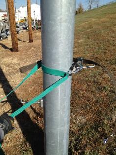
6 One commonly used fall restraint system is the Buckingham SuperSqueeze with a rope auxiliary safety strap. Several other suppliers of climbing equipment offer similar fall restraint systems. Each supplier should be consulted about the equipment and its use for climbing steel poles. PREPARING TO CLIMB A STEEL UTILITY POLE Preparing to climb a steel pole is no different than a wood pole. Climbing equipment should be inspected for defects and, if any are found, the equipment should be replaced or repaired before ascending. The area around the pole should be free of equipment and debris. The line technician should visually inspect the pole and choose the climbing route that appears to be the safest. While ascending and descending, care should be taken to remain aware of the surroundings to avoid any climbing hazards. Always inspect the pole before starting your climb. Keep these and other safety tips in mind when ascending or descending a steel or wood utility pole. USING A WORK PLATFORM One of the most common concerns about working on steel poles is the challenge of trying to work at an elevation from a single position. To work around this challenge, a simple work platform can be used. The work platform is easily installed at almost any location along the pole, providing the line worker freedom to move about the pole and work area. A platform option would be used in conjunction with the previously mentioned step attachments to ascend and descend the pole. For more information about working with steel utility poles in a de-energized setting, visit lineman.steel.org. Page 25
7
8 STUDENT QUIZ 1. When climbing steel poles, which item of climbing equipment will not be used? a. Climbers b. Body belt c. Hard toe boots d. Safety strap or fall protection system 2. How are steel poles climbed? a. In the same manner as wood poles. b. By attaching strong magnets to the line worker s feet. c. By installing steps into the steel pole. d. By using a scaffolding system. 3. Which of the following step systems require the use of a rivnut? a. Hubbell-Chance Step System b. Senior Step System c. Valmont Newmark Step System d. All of these answers. 4. What should be done before ascending a steel pole? a. Inspect the pole for hazards. b. Clear the area around the pole of tools, material and debris. c. Inspect climbing equipment for defects. d. All of these answers. 5. Steps that are installed on steel poles are permanent fixtures on the pole. a. True b. False 6. The holes drilled in a steel pole to accommodate steps are the same diameter regardless of which pole step system is used. a. True b. False Page 27
9 7. Which of the following options can make working aloft on a steel pole more comfortable and easier to reach the work? a. Place steps strategically. b. Attach a work platform. c. Install a steel collar to the pole. d. Only A & B e. None of these answers. 8. If the utility decides to leave pole steps in permanently, what precaution should be considered? a. Make sure the steps are installed securely. b. Remove lower steps to prevent unauthorized persons from climbing the pole. c. Be sure to charge the steps to the proper work order. d. Steps should never be permanently installed on steel poles. Page 28
10 STUDENT QUIZ ANSWER KEY 1. When climbing steel poles, which item of climbing equipment will not be used? a. Climbers b. Body belt c. Hard toe boots d. Safety strap or fall protection system 2. How are steel poles climbed? a. In the same manner as wood poles. b. By attaching strong magnets to the line worker s feet. c. By installing steps into the steel pole. d. By using a scaffolding system. 3. Which of the following step systems require the use of a rivnut? a. Hubbell-Chance Step System b. Senior Step System c. Valmont Newmark Step System d. All of these answers. 4. What should be done before ascending a steel pole? a. Inspect the pole for hazards. b. Clear the area around the pole of tools, material and debris. c. Inspect climbing equipment for defects. d. All of these answers. 5. Steps that are installed on steel poles are permanent fixtures on the pole. a. True b. False 6. The holes drilled in a steel pole to accommodate steps are the same diameter regardless of which pole step system is used. a. True b. False Page 29
11 7. Which of the following options can make working aloft on a steel pole more comfortable and easier to reach the work? a. Place steps strategically. b. Attach a work platform. c. Install a steel collar to the pole. d. Only A & B e. None of these answers. 8. If the utility decides to leave pole steps in permanently, what precaution should be considered? a. Make sure the steps are installed securely. b. Remove lower steps to prevent unauthorized persons from climbing the pole. c. Be sure to charge the steps to the proper work order. d. Steps should never be permanently installed on steel poles. Page 30
12 Working with Steel Utility Poles Page 31

13 Safety First Hard Hat Safety Glasses Leather Gloves Proper Clothing Page 32

14 Overview Inspections Pole Surrounding area Climbing equipment Follow Company Safety Practices Page 33

15 Pole Steps Typically removable Types of Steps Hubbell-Chance Step Senior Step Valmont Newmark Step Page 34
 Senior Step 13/16 inch Valmont Newmark")
16 Hole is Required Each step system requires a certain diameter hole. Hubbell-Chance Step 13/32 inch (for rivnut) Senior Step 13/16 inch Valmont Newmark Step 1-1/8 inch Page 35


17 Hubbell-Chance Rivnut Step 13/32 hole Rivnut threaded insert Face plate Mounting bolt Face Plate & Mounting Bolt Page 36


18 Install Step Hubbell-Chance Step Removable slip-on foot step Remove Step Page 37


19 Senior Step 13/16 hole Foot step bolt Foot Step Bolt Face plate Face Plate Page 38


20 Senior Step Star Washer Star washer Locking bolt Locking Bolt Page 39

21 Valmont Newmark Step 1-1/8 hole Cast step peg Cast Step Peg Page 40

22 Valmont Newmark Step Step Bolt & 2 Locking Nuts Step bolt 2 locking nuts Page 41

23 Climbing Equipment Standard body belt Fall protection system Auxiliary safety strap Hard toe boots with good arch support Page 42


24 Linemen with proper fall protection Page 43

25 Working Aloft Step placement Work platforms Page 44
26 Review Steel poles can be climbed by installing temporary or permanent steps. A hole is required to be drilled to accommodate the step. There are three step systems and the hole diameters are: Hubbell-Chance Step System 13/32 Senior Step System 13/16 Valmont Newmark Step System 1-1/8 Climbing equipment required by your company can be used to climb steel poles. Always inspect the pole and area around the pole before climbing. Pole steps can be strategically arranged at the elevated work location for comfort and ease of work. Work platforms can be used at elevated positions. Page 45
27 Page 46
28 INSTRUCTOR TRAINING GUIDE LAB SESSION WITH SKILLS ASSESSMENT LEARNING OBJECTIVES Students will demonstrate installing and removing steps while ascending and descending the steel pole. Students will complete a simple job at the top of the steel pole. INSTRUCTOR REFERENCE Video on Climbing Steel Poles - this can be viewed online (lineman.steel.org) or via the provided DVD or USB. Additional general material provided at lineman.steel.org. MATERIALS Pre-drilled steel pole set with crossarm installed Steps of instructor s choosing (if you need complimentary steps, please contact SMDI at or dsnyder@steel.org) The Hubbell-Chance Step System The Senior Step System The Valmont Newmark Step System Climbing Gear Personal Protective Equipment Pin and insulator STUDENT PREPARATION Complete the online or classroom lesson on climbing steel poles (video, lecture, and quiz). Have experience in general field activities - deployment, joining, drilling, framing and installing a pole (wood or another material). TRAINING ACTIVITY A job briefing (tailgate) will be led by the instructor and cover the following subjects: Job site and equipment inspections Description of the job to be completed Open discussion on safety considerations Students will practice installing and removing steps before climbing. Students will ascend the pole, installing steps as they climb. Students will secure the handline to the crossarm. Students will install and remove a pin and insulator on the crossarm. Students will descend the pole, removing steps as they climb down. Instructor will lead a short debriefing of the activity and answer questions. Page 47
29 STUDENT ASSESSMENT If the instructor wishes to assign a grade to the student on the activity, the following guidelines are suggested for assessing the student s work: Active participation in the activity Attention to detail and safety Climbing ability Ability to work at the crossarm location Ability to complete the activity Page 48
Side-of-Pole Mount for 1 Module (SPM1) For Module Types A & B
 For Module Types A & B") Side-of-Pole Mount for 1 Module (SPM1) For Module Types A & B ASSEMBLY INSTRUCTIONS step-by-step assembly and installation Version 1, Rev A PCN 080311-2 SP3363-1 Side-of-Pole Mount for 1 Module (SPM1)
Side-of-Pole Mount for 1 Module (SPM1) For Module Types A & B ASSEMBLY INSTRUCTIONS step-by-step assembly and installation Version 1, Rev A PCN 080311-2 SP3363-1 Side-of-Pole Mount for 1 Module (SPM1)
8MAY15 US RACK, Inc Falcon Drive, Madera, CA
 8MAY15 US RACK, Inc. - 2850 Falcon Drive, Madera, CA 93637-559-661-3050 INSTRUCTIONS for Bedrail-mounted MOTORCYCLE RACK, Model 2001-4TRA WARNING: Do NOT attempt to install or use this rack without following
Troyer s Gourd Rack 8 unit F R H O P
 B E A D I M-N L Vertical Parts F R H O P Horizontal Parts C G J Updated 11/16 Parts List A: Top of Pole B: Bottom of Pole C: 48 Ground Stake D: Top Perch rods 48 long E: Hub F: Rope Winder w/ attached
Stand-N-Fish FULL DETAIL INSTALLATION INSTRUCTIONS
 1 Stand-N-Fish FULL DETAIL INSTALLATION INSTRUCTIONS Thank you for purchasing the incredible new Stand-N-Fish Kayak Fishing System. Once installed on your kayak the Stand-N-Fish will take your kayak fishing
Assembly Instructions. -Cantilever Boat Lifts
 Assembly Instructions -Cantilever Boat Lifts Winch Instruction Page Safety Information 1. The winch is built for the multipurpose of hauling and lifting operations. It is not to be used as a hoist for
FIRST TEAM SPORTS, INC Storm Portable Series Assembly Instructions
 FIRST TEAM SPORTS, INC Storm Portable Series Assembly Instructions WARNING! WARNING! WARNING! THIS BASKETBALL SYSTEM IS SPRING LOADED AND SHIPPED UNDER TENSION. ATTEMPTING TO ASSEMBLE OR DISASSEMBLE ANY
IMPORTANT: RECEIVING INSTRUCTIONS:
 Instruction Sheet Sidewinder Mechanical Bender IMPORTANT: RECEIVING INSTRUCTIONS: Visually inspect all components for shipping damage. If any shipping damage is found, notify carrier at once.shipping damage
2018 Public Power Lineworkers Rodeo General Rules for All Rodeo Competitors
 2018 Public Power Lineworkers Rodeo General Rules for All Rodeo Competitors 1. All safety rules are to be observed during events. 2. A competitor may not compete if bleeding. 3. Rubber gloves are required
Safety System Installation Guide for ARE Wind Poles
 Safety System Installation Guide for ARE Wind Poles V. 1 May 2011 ** Climbing pegs and ladder should be installed before the pole is erected.** A. Install climbing pegs Install climbing pegs (bolt set)
Marine 6-Boat Free-Standing Racks SKU: Updated November 2011
 Marine 6-Boat Free-Standing Racks SKU: 30-061 Updated November 011 Contains: Marine -Boat Free-Standing Racks (SKU 1-003) Marine 3 rd Boat Expansion Racks (SKU 1-0303) Marine Back Legs (SKU -001) 3 Sets
KERSPLASH POOL CLIMBING WALL INSTALLATION INSTRUCTIONS
 TOLL FREE: 1-800-476-7366 VOICE 651-665-9131 FAX 651-665-9130 EMAIL: INFO@POOLCLIMBINGWALLS.COM EVERLAST CLIMBING 1335 MENDOTA HEIGHTS ROAD MENDOTA HEIGHTS, MN 55120 2012 EVERACTIVE BRANDS Congratulations!
Tripod Setup Guide (M-TPx)
") Items needed: 1/2 inch wrench, mast level (M-MLA), medium size wire cutters, crescent wrench, all-purpose grease, tape measure, tie wraps, redi-mix cement (optional), shovel (optional), sledge hammer (for
Items needed: 1/2 inch wrench, mast level (M-MLA), medium size wire cutters, crescent wrench, all-purpose grease, tape measure, tie wraps, redi-mix cement (optional), shovel (optional), sledge hammer (for
Apprentice Event Written Test Chief Judge: David Benenhaley
 Apprentice Event Written Test Chief Judge: David Benenhaley Event Time: N/A Drop-Dead Time: 15 Minutes Summary: This event is a written test compiled of 24 true/false and multiple-choice safety knowledge
Deans, Directors, Heads of Schools and Departments and Research Institute Directors and Managers
 Working at Height 1. PURPOSE 1.1 To ensure that any work at height is carried out in accordance with the legal requirements and associated guidance. This includes the use of scaffolds, towers, ladders,
"FALL PROTECTION IN CONSTRUCTION ENVIRONMENTS"
 MAJOR PROGRAM POINTS "FALL PROTECTION IN CONSTRUCTION ENVIRONMENTS" Part of the "CONSTRUCTION SAFETY KIT" Series Quality Safety and Health Products, for Today...and Tomorrow OUTLINE OF MAJOR PROGRAM POINTS
QUALITY ALUMINUM BOAT LIFTS, INC. INSTRUCTIONS. Dominator Lake Lift
 INSTRUCTIONS Dominator Lake Lift PHONE:251-986-3882 * FAX:251-986-3136 QABLDOMINATORINST.2014 P a g e 1 Quality Aluminum Boat Lifts, INC. Installation Instructions: Dominator Lake Lift Thank you for your
PRODUCT CARD WALL MOUNTED FIXED BASKETBALL CONSTRUCTION PROJECTION: FROM 1,00 TO 2,25 M
 PRODUCT CARD WALL MOUNTED FIXED BASKETBALL CONSTRUCTION PROJECTION: FROM 1,00 TO 2,25 M I. List of components... 2 II. Complimentary products... 2 III. Product description... 3 IV. Product Purpose... 3
Lock-N-Load. Bullet Feeder
 Lock-N-Load Bullet Feeder table of contents steps Overview... 2 List of required hand tools... 2 1: Mounting the Bullet Feeder to the Bench... 3 2: Mounting the Bullet Feed Hopper... 4 3: Bullet Feed Hopper
USER MANUAL Do not throw away these instructions. Read and understand these instructions prior to use of the Lad Grab Safety System.
 PRODUCT NAME: LAD GRAB Patent Pending PART NUMBERS: *LAD GRAB2TOPBRACKET, *LAD GRAB2CABLEGUIDE, *LAD GRAB2BOTTOMBRACKET, & CABLE3/8AIRCRAFT USER MANUAL Do not throw away these instructions. Read and understand
VERSA BIKE RACK INSTRUCTIONS
 VERSA BIKE RACK INSTRUCTIONS Models #8, 8 Important This rack is designed for use with a or. receiver hitch. The rack is designed to hold a maximum of two bicycles. Do not use it for anything other than
INSTALLATION INSTRUCTIONS FOR EXHAUST CUFF MODIFICATION
 INSTALLATION INSTRUCTIONS FOR EXHAUST CUFF MODIFICATION Document # PCA1001-22 Revision LTR: A Date: 07/06/09 1 Notes: 1. The cuff must be installed onto the aircraft prior to painting. Once installed the
Reliance Industries, LLC Operating instructions for the / Bolt-on D-Ring Anchorage. Model # 3071
 Reliance Industries, LLC Operating instructions for the 3071-1 / 3071-2 Bolt-on D-Ring Anchorage Model # 3071 Reliance Industries, LLC PO Box 140008 Denver, CO 80214 Ph. (800) 488-5751 Ph. (303) 424-8650
PRODUCT CARD WALL MOUNTED SIDE FOLDED BASKETBALL CONSTRUCTION PROJECTION: FROM 1,2 TO 2,45 M
 PRODUCT CARD WALL MOUNTED SIDE FOLDED BASKETBALL CONSTRUCTION PROJECTION: FROM 1,2 TO 2,45 M I. List of components... 2 II. Complimentary products... 2 III. Product description... 3 IV. Product Purpose...
Change Crossarm Insulator with Hotsticks
 Change Crossarm Insulator with Hotsticks S T U D E N T M A N U A L March 31, 2005 2 STUDENT TRAINING MANUAL Prerequisites: Introduction to Hotsticks module Use and Care of Hotsticks module Weights & Forces
Key provisions of OSHA's new rule on walking/working surfaces, fall protection
 ARTICLES CASES Key provisions of OSHA's new rule on walking/working surfaces, fall protection Although an overwhelming majority of general industry accidents stem from slips, trips and falls, Subpart D
602 STRINGING MACHINE OWNER'S MANUAL
 PROGRESSION 602 STRINGING MACHINE OWNER'S MANUAL AL Issue 1- April 2000 Copyright 2000 GAMMA Sports - All Rights Reserved PROGRESSION 602 STRINGING MACHINE TABLE OF CONTENTS PAGE 1... WARRANTY PAGE 2...
INSTALLATION INSTRUCTIONS
 INSTALLATION INSTRUCTIONS Accessory (ROOF) P/N 08L07-E09-100 Application 6 PILOT Publications No. Issue Date JUN 5 PARTS LIST 6 Washers Bicycle attachment 2 Brackets Hex wrench 4 Knobs 2 Keys 1 Rear Bracket
STAND AID 1600/ ECONOSTAND
 MAKERS OF STAND AID, POWER TOILET AID AND FREEDOM CHAIR STAND AID 600/ ECONOSTAND INSTRUCTIONS AND WARRANTY FOR STAND AID 600 STAND AID SERIAL # PO BOX 386 Sheldon, IA 50 (800) 83-8580 (7) 34-53 Fax: (7)
INSTALLATION INSTRUCTIONS FOR ROLLOVER PROTECTION SYSTEM (ROPS)
") INSTALLATION INSTRUCTIONS FOR ROLLOVER PROTECTION SYSTEM (ROPS) This manual contains assembly, operating, maintenance and safety instructions for your ROPS. Before Installing the ROPS or operating a machine
INSTALLATION INSTRUCTIONS FOR ROLLOVER PROTECTION SYSTEM (ROPS) This manual contains assembly, operating, maintenance and safety instructions for your ROPS. Before Installing the ROPS or operating a machine
Shoreline Cantilever Lift 2500lb Capacity Models: (108" inside width) - Part # (120" inside width) - Part #
 - Part # (120 inside width) - Part #") Shoreline Cantilever Lift 2500lb Capacity Models: 25108 (108" inside width) - Part # 1017402 25120 (120" inside width) - Part # 1017403 1. 2. 3. 4. 5. CAUTION - PUT SAFETY FIRST Before attempting to install
Shoreline Cantilever Lift 2500lb Capacity Models: 25108 (108" inside width) - Part # 1017402 25120 (120" inside width) - Part # 1017403 1. 2. 3. 4. 5. CAUTION - PUT SAFETY FIRST Before attempting to install
STATIONARY TRUCK INTERNAL HALYARD V-CLEAT FLAGPOLES FOR QUICK AND PROFESSIONAL INSTALLATION READ ALL INSTRUCTIONS BEFORE PROCEEDING
 9390 South 300 West, Sandy, Utah 84070 801-562-0123 800-782-0500 ColonialFlag.com STATIONARY TRUCK INTERNAL HALYARD V-CLEAT FLAGPOLES FOR QUICK AND PROFESSIONAL INSTALLATION READ ALL INSTRUCTIONS BEFORE
Assembling a Can Sealer FNH-00022
 Assembling a Can Sealer FNH-00022 Technical revision in January 2009 by Kristy Long Extension Foods Specialist Cooperative Extension Service University of Alaska Fairbanks Photos by Jeff Fay Extension
Installation and Training Manual
 AirForce1 Tower Kit Installation and Training Manual FuturEnergy Limited Ettington Park Business Centre Stratford upon Avon CV37 8BT +44 (0)1789 451070 Table of Contents Safety Notes... 3 Parts Supplied
MAGNETIC INDOOR CYCLING BIKE
 MAGNETIC INDOOR CYCLING BIKE SF-B1805 USER MANUAL IMPORTANT! Please retain owner s manual for maintenance and adjustment instructions. Your satisfaction is very important to us, PLEASE DO NOT RETURN UNTIL
USER S MANUAL QUESTIONS? CAUTION. Model No. FMEX Serial No. Write the serial number in the space above for reference. Serial Number Decal
 Model No. FMEX81110.0 Serial No. Write the serial number in the space above for reference. USER S MANUAL Serial Number Decal QUESTIONS? If you have questions, or if parts are damaged or missing, please
Parts: Included in the parts box: Inner Rear Tire Tray. Inner Front Tire Tray. Trail Doc Clamp. Pivot Assembly. Trail Doc Post.
 NV 2.0 2 Parts: Outer Front Tire Tray Inner Front Tire Tray Outer Rear Tire Tray Inner Rear Tire Tray Pivot Assembly Trail Doc Clamp Trail Doc Post Included in the parts box: 6mm Allen Wrench M6 Lock Washer
Important Note: Tighten lock nuts so the support tubes still swing freely see figure 2. There must be 1 2 threads of bolt past end of lock nuts.
 Kit Contents: DESCRIPTION QTY. DESCRIPTION QTY. 2 Shank Assembly 1 Support Tube Assembly 1 Side Tube - Short 2 1-1/4 Shank 1 Center Tube - Long 1 3/8-16 x 2.0 Carriage Bolt 2 5/16-18 x 2.25 Carriage Bolt
"RIGGING SAFETY IN CONSTRUCTION ENVIRONMENTS"
 PRESENTER'S GUIDE "RIGGING SAFETY IN CONSTRUCTION ENVIRONMENTS" Part of the "CONSTRUCTION SAFETY KIT" Series Quality Safety and Health Products, for Today...and Tomorrow OUTLINE OF MAJOR PROGRAM POINTS
OWNER'S MANUAL. Copyright 1999 ATS - All Rights Reserved
 OWNER'S MANUAL AL Issue 2 - August 19, 1999 Copyright 1999 ATS - All Rights Reserved OWNER'S MANUAL TABLE OF CONTENTS PAGE 1... WARRANTY PAGE 2... ASSEMBLY INSTRUCTIONS PAGE 4... MOUNTING THE RACQUET PAGE
Side-of-Pole Mount for 1 Module (SPM1) For Module Type C
 For Module Type C") Module Type Width Length C 22-27 56-63 Side-of-Pole Mount for 1 Module (SPM1) For Module Type C ASSEMBLY INSTRUCTIONS step-by-step assembly and installation Version 1, Rev A PCN 022212-1 Side-of-Pole Mount
Module Type Width Length C 22-27 56-63 Side-of-Pole Mount for 1 Module (SPM1) For Module Type C ASSEMBLY INSTRUCTIONS step-by-step assembly and installation Version 1, Rev A PCN 022212-1 Side-of-Pole Mount
RATCHET RELEASE SHACKLE
 RATCHET RELEASE SHACKLE INNOVATIVE PILING EQUIPMENT HYDRAULIC PILING HAMMERS EURO RATCHET RELEASE SHACKLE FOR STEEL ERECTION OPERATORS INSTRUCTIONS & SPARE PARTS LIST EXCAVATOR MOUNTED VIBRATORS EXCAVATOR
Important Safety Information for Users of. Bashlin Climbers
 Important Safety Information for Users of Bashlin Climbers - WA R NING For your personal safety, this booklet must be completely read and all of the information understood completely before using these
SERIES 2 RAMP OWNER S MANUAL TOOLS REQUIRED: BEFORE YOU BEGIN... Read and understand these instructions before beginning a ramp setup.
 SERIES 2 RAMP OWNER S MANUAL BEFORE YOU BEGIN... Read and understand these instructions before beginning a ramp setup. Use caution and care for your back when lifting, pushing, pulling, folding or unfolding
GRAVITY BIKE RACK ASSEMBLY & OPERATING INSTRUCTIONS
 GRAVITY BIKE RACK 94479 ASSEMBLY & OPERATING INSTRUCTIONS Due to continuing improvement, actual product may differ slightly from the product described herein. 3491 Mission Oaks Blvd., Camarillo, CA 93011
WEIGHT STACK ATTACHMENT. Assembly Manual (888) FOR YOUR SAFETY READ ALL INSTRUCTIONS CAREFULLY
 FOR YOUR SAFETY READ ALL INSTRUCTIONS CAREFULLY") WEIGHT STACK ATTACHMENT Assembly Manual DF835 (888) 258-0533 FOR YOUR SAFETY READ ALL INSTRUCTIONS CAREFULLY *NOTE IF YOU ARE MISSING HARDWARE OR HAVE ANY FIT UP PROBLEMS PLEASE CONTACT DELTECH FITNESS
WEIGHT STACK ATTACHMENT Assembly Manual DF835 (888) 258-0533 FOR YOUR SAFETY READ ALL INSTRUCTIONS CAREFULLY *NOTE IF YOU ARE MISSING HARDWARE OR HAVE ANY FIT UP PROBLEMS PLEASE CONTACT DELTECH FITNESS
#59114 Rola 2-Bike Rack Carrier (Shown Assembled) (A) (C) (B)
 (A) (C) (B)") Use for Parts: #59114 Rola -Bike Rack System #59115 Rola 1-Bike Add-On TOOLS REQUIRED 10mm or 13/3 Socket & Wrench #59114 Rola -Bike Rack Carrier (Shown Assembled) Tray Attachment Hardware: (3) Plastic
Use for Parts: #59114 Rola -Bike Rack System #59115 Rola 1-Bike Add-On TOOLS REQUIRED 10mm or 13/3 Socket & Wrench #59114 Rola -Bike Rack Carrier (Shown Assembled) Tray Attachment Hardware: (3) Plastic
Installation, Operating, Inspection and Maintenance Instructions Ladder Climber s Safety System. Warning
 OWNER'S MANUAL Installation, Operating, Inspection and Maintenance Instructions Ladder Climber s Safety System Model # s: 6000, 6001, 6010 Warning You must read and fully understand all instructions, or
-- SGP (NOVA TEAM SQUARE)
") -- SGP-100 -- (NOVA TEAM SQUARE) Installation Instructions Call Jaypro Sports Equipment at 1-800-243-0533 during regular business hours for technical support. www.jaypro.com Rev-B Page 1 of 9 JAYPRO SPORTS
-- SGP-100 -- (NOVA TEAM SQUARE) Installation Instructions Call Jaypro Sports Equipment at 1-800-243-0533 during regular business hours for technical support. www.jaypro.com Rev-B Page 1 of 9 JAYPRO SPORTS
E. Test, and if needed, adjust tips of antenna. 1. Mark will test antennas with meter at ground end of feedline bundle. Will take 10 minutes.
 Project Steps Overview: A. Prepare: B. Raise up small antenna. C. Raise up large antenna. D. Connect to new bundle of 4-feedlines pulled up from ground. E. Test, and if needed, adjust tips of large antenna.
FALL PROTECTION. Leader s Guide. Marcom Group Ltd.
 1818 FALL PROTECTION Leader s Guide Marcom Group Ltd. Structure and Organization Information in this program is presented in a definite order, so that employees will see the relationships between the various
CHAINLESS ANCHORING SYSTEM USER MANUAL
 CHAINLESS ANCHORING SYSTEM USER MANUAL Introduction..................................................... 1 Setting up the Chainless Anchoring System............................ 4 Set up Procedure............................................
600 / 600FC OWNER'S MANUAL
 PROGRESSION 600 / 600FC OWNER'S MANUAL Issue 2 / Version E - Dec. 10, 1997 Copyright 1997 GAMMA Sports - All Rights Reserved PROGRESSION 600 / 600FC OWNER'S MANUAL TABLE OF CONTENTS PAGE 1... WARRANTY
SAFETY FIRST. Inspection Proper Set Up Proper Climbing & Use Proper Storage & Carrying Operating Instructions
 SAFETY FIRST Inspection Proper Set Up Proper Climbing & Use Proper Storage & Carrying Operating Instructions Max weight on the 18 inch platforms 500 pounds SWL Certified at 2,000 pounds. Qualified under
OWNER'S MANUAL LOCK-N-LOAD BULLET FEEDER (PISTOL)
") OWNER'S MANUAL LOCK-N-LOAD BULLET FEEDER (PISTOL) Table of Contents ASSEMBLY ASSEMBLY Pistol Bullet Feeder... Page 3 CHANGE-OVERS The Hornady Lock-N-Load Pistol Bullet Feeder is capable of feeding most
OWNER'S MANUAL LOCK-N-LOAD BULLET FEEDER (PISTOL) Table of Contents ASSEMBLY ASSEMBLY Pistol Bullet Feeder... Page 3 CHANGE-OVERS The Hornady Lock-N-Load Pistol Bullet Feeder is capable of feeding most
Constitution Instructions
 Constitution Instructions This kit will build a 1:48 scale hull for the USS Constitution frigate. The kit contains the following parts. 1/8 deck with laser etched deck lines 1/8 railing Ribs Center keel
BELT DRIVE INDOOR CYCLING BIKE SF-B1712 USER MANUAL
 BELT DRIVE INDOOR CYCLING BIKE SF-B1712 USER MANUAL IMPORTANT! Please retain owner s manual for maintenance and adjustment instructions. Your satisfaction is very important to us, PLEASE DO NOT RETURN
Troubleshooting Guide
 Troubleshooting Guide This troubleshooting guide outlines quick fixes to the most common technical questions about the ElliptiGO. If the problem persists or you feel uncomfortable performing these actions,
CHAPTER 10 FALL PROTECTION
 CHAPTER 10 FALL PROTECTION A. INTRODUCTION... 1 B. CHAPTER-SPECIFIC ROLES and RESPONSIBILITIES... 2 C. HAZARD IDENTIFICATION... 3 1. Job Hazard Analysis (Jha).... 3 2. Fall Hazards... 3 D. HAZARD CONTROL...
Caliber Sled Wheels Assembly Instructions for PN and 13579
 Caliber Sled Wheels Assembly Instructions for PN 13576 and 13579 Caution: Read all instructions before assembling or using Sled Wheels. Follow the steps in order. Only use Sled Wheels as intended, following
BICYCLE TO MOTORCYCLE BICYCLE RACK
 BICYCLE TO MOTORCYCLE BICYCLE RACK Install Manual Warning: You are responsible for securing the rack to your motorcycle., checking the attachments prior to use and periodically inspecting the products
Climbing Stick OWNER S MANUAL
 Climbing Stick OWNER S MANUAL table of contents Warnings and Terms & Conditions... 3 Installation Process... 8 Uninstallation Process... 11 HTOUTDOOR.COM 2 Warnings; Assumption Of Risk; Waiver of Warranties
INSTRUCTION GUIDE S-WORKS ROAD CARBON CRANKSET (Carbon and Alloy OSBB cups)
") INSTRUCTION GUIDE S-WORKS ROAD CARBON CRANKSET (Carbon and Alloy OSBB cups) THIS BRIEF INSTRUCTION GUIDE CONTAINS IMPORTANT INFORMATION. PLEASE READ CAREFULLY AND STORE IN A SAFE PLACE. Congratulations!
INSTRUCTION GUIDE S-WORKS ROAD CARBON CRANKSET (Carbon and Alloy OSBB cups) THIS BRIEF INSTRUCTION GUIDE CONTAINS IMPORTANT INFORMATION. PLEASE READ CAREFULLY AND STORE IN A SAFE PLACE. Congratulations!
Thank you for purchasing a WIKE BOX BIKE!
 Thank you for purchasing a WIKE BOX BIKE! Contents Safety.....3 Front wheel.4 Kickstand..5 Handle Bar & Box 6 Seat post and Saddle 7 Final pre-ride check 8 Tools needed to assemble Bike: -High table or
TOWER INSPECTION REPORT
 3010 S. Hwy 77, Suite 600 Waxahachie, Texas 75165 http://ctctower.com Office: 972/923-9504 Fax: 972/923-9619 TOWER INSPECTION REPORT PREPARED FOR MR. CUSTOMER 1,563 GUYED TOWER NEAR CITY, STATE JANUARY
2,500/4,000 LB Easy Riser Vertical Cable Feighner Lift
 2,500/4,000 LB Easy Riser Vertical Cable Feighner Lift CAUTION - PUT SAFETY FIRST 1. Before attempting to install or operate this lift, study and fully understand the proper operating procedures and safety
INSTALLATION INSTRUCTIONS. Parts List. Tools Required. Before You Begin. Installation. Customer Information BICYCLE ATTACHMENT JUL.
 INSTALLATION INSTRUCTIONS JUL. 2006 Parts List Bicycle attachment Key plates (2) Tools Required Phillips screwdriver Flat-tip screwdriver Before You Begin Customer Information This Bicycle Attachment is
Trilogy Theory of Operation
 INSTALLATION & OVERVIEW... 2 Load Height... 2 Approach Angle... 2 Footprint... 3 Protrusion... 3 Mounting the... 4 General Torque Specs... 4 OPERATION OF BIKE RACK... 5 Loading Bikes... 5 Unloading Bikes...
DIRECT DRIVE DIXIE DOUBLE SEAMER Model 25D
 OPERATOR'S MANUAL DIRECT DRIVE DIXIE DOUBLE SEAMER Model 25D LUBRICATE DAILY: A. Gears inside gear housing at chuck shaft (1) Oil B. Seam rolls and cam rolls (4) - Oil C. Seam roll levers through gear
User s Manual. Model SWTC800. CAUTION: Adult Assembly Required
 User s Manual Model SWTC800 CAUTION: Adult Assembly Required Model SWTC800...3...4...4...5...6.........8...9...10-11 Part Identification Chart... 12 Exploded Drawing and Parts List...13-14 Ordering Replacement
OUTDOOR BACKSTOP WITH 5'-0" EXTENSION
 INSTALLATION INSTRUCTIONS OUTDOOR BACKSTOP WITH 5'-0" EXTENSION NoUU. 00175- _ READ ALL INSTRUCTIONS THOROUGHLY BEFORE ATTEMPTING TO INSTALL THIS EQUIPMENT. INSTALLATION / ASSEMBLY OF THIS EQUIPMENT MUST
L.Ph. Bolander & Sons 1355 Evans Ave. 800/
 L.Ph. Bolander & Sons 1355 Evans Ave. 800/434-5611 San Francisco, Ca. 94124 Fax 415/648-0402 GOUNDSET ALUMINUM FLAGPOLE INSTALLATION INSTRUCTIONS STEP 1: DIG THE HOLE TO THE DIMENSIONS LISTED BELOW STEP
The purpose of this training is to give field technicians awareness training and guidelines on potential hazards they may encounter in the field.
 Purpose The purpose of this training is to give field technicians awareness training and guidelines on potential hazards they may encounter in the field. Fall Protection and Prevention JELD-WEN Field Employees
WINCH USER GUIDE WARN 3700 Utility Winch Part Number: 93700
 WINCH USER GUIDE WARN 3700 Utility Winch Part Number: 93700 Your safety, and the safety of others, is very important. To help you make informed decisions about safety, we have provided installation and
Introduction to Evolutionary Hoof Care s New Hoof Care Work Stations TM and Evo Hoof Stands TM Also see Video Instructions at
 Introduction to Evolutionary Hoof Care s New Hoof Care Work Stations TM and Evo Hoof Stands TM Also see Video Instructions at www.evohoofcare.com This new generation of hoof support devices will significantly
PRO1030 Bi-Directional Assembly Replacement
 PRO1030 Bi-Directional Assembly Replacement 1. Remove both side covers using the Crank and Cover Removal procedure. Fig. 1 2. Disconnect both brake cables (not shown) from the brake (S3611). (Fig. 1) 3.
FALL PROTECTION GUIDELINE
 FALL PROTECTION GUIDELINE July 2001 Table of Contents INTRODUCTION...3 CONTROL MEASURES...4 SURFACE PROTECTION...4 FIXED BARRIERS...5 EXAMPLES OF GUARDRAIL...6 WARNING BARRIERS...7 HANDRAILS...8 SURFACE
EZee Glider Manual. Tools needed for Assembly: Wrench (included) Philips Screwdriver (not included) Assembly Instructions
 Philips Screwdriver (not included) Assembly Instructions") EZee Glider Manual Congratulations on your purchase of the EZee Glider! Your glider is designed for years of nearly carefree use by your child. These instructions include how to set up your glider and
EZee Glider Manual Congratulations on your purchase of the EZee Glider! Your glider is designed for years of nearly carefree use by your child. These instructions include how to set up your glider and
"FALL PREVENTION IN THE WORKPLACE"
 MAJOR PROGRAM POINTS "FALL PREVENTION IN THE WORKPLACE" Part of the "GENERAL SAFETY SERIES" Quality Safety and Health Products, for Today...and Tomorrow Outline of Major Points Covered in the "Fall Protection"
C - SERIES. Height Adjustable Portable Goal Supports. Installation & Owner s Instructions C1000 C2000. Made in the USA
 C - SERIES Height Adjustable Portable Goal Supports C1000 C2000 Installation & Owner s Instructions Made in the USA This manual explains the proper installation, operation, and maintenance of your Schutt
INSTALLATION INSTRUCTIONS
 INSTALLATION INSTRUCTIONS Accessory (ROOF) P/N 08L07-E09-100 Application 2013 CROSSTOUR Publications No. AII 13168 Issue Date NOV 2012 PARTS LIST 6 Washers Bicycle attachment 2 Brackets Hex wrench 4 Thumbwheel
Side-of-Pole Mount for 1 Modules (SPM1) For Module Types E, F, G, & H ASSEMBLY INSTRUCTIONS. step-by-step assembly and installation
 For Module Types E, F, G, & H ASSEMBLY INSTRUCTIONS. step-by-step assembly and installation") Side-of-Pole Mount for 1 Modules (SPM1) For Module Types E, F, G, & H ASSEMBLY INSTRUCTIONS step-by-step assembly and installation Version 1, Rev A SP3348-1 PCN 022212-2 Side-of-Pole Mount for 1 Module
Side-of-Pole Mount for 1 Modules (SPM1) For Module Types E, F, G, & H ASSEMBLY INSTRUCTIONS step-by-step assembly and installation Version 1, Rev A SP3348-1 PCN 022212-2 Side-of-Pole Mount for 1 Module
Installation Instructions MODEL VSTI-A020 Tank Indicator Installation Model: VSTI-A020, Stainless Reverse Read System Versa Steel Inc. Guide Cables No
 Tank Indicator Installation Model: VSTI-A020, Stainless Reverse Read System Guide Cables No Guide Cables 1 August 4, 2011 Assembly Instructions: (Shown with a 2 board, 12 ft kit) ITEM NO. PART NUMBER DESCRIPTION
Installation Guide RHT-380. This Manual Must Be Read Before Operating The Equipment CUSTOMER COPY
 Installation Guide This Manual Must Be Read Before Operating The Equipment RHT-380 Madison Heights, Michigan 48071 800-725-8377 www.snowexproducts.com CUSTOMER COPY Trynex International 2013 (REV B) F50767
Cable Replacement Instructions for R-Series Roust-A-Bout 100/150/250
 Cable Replacement Instructions for R-Series Roust-A-Bout 100/150/250 US 7514 Alabonson Road Houston, TX 77088 phone: 281-999-6900 fax: 281-999-6966 Canada 1721 Bishop St. Unit #4 Cambridge, ON N1T 1N5
BALL STOP INSTALLTION GUIDE
 BALL STOP INSTALLTION GUIDE GROUND SLEEVE INSTALLATION: 1. Locate the exact location of the ground sleeve. NOTE: Maximum recommended pole spacing is 20 feet on center. 2. Excavate the pole footing; refer
IMPORTANT SAFETY NOTICE
 OWNER S MANUAL NOTE: Any photos of the YBIKE or decals in the owner s manual are intended to be used as a reference only, and there may be some differences to the unit you purchased. IMPORTANT SAFETY NOTICE
NICROS-GRANITPANELS INSTALLATION MANUAL
 NICROS-GRANITPANELS INSTALLATION MANUAL NICROS, INC. 845 PHALEN BLVD. ST. PAUL, MN 55106 PHONE: 651.778.1975 FAX: 651.778.8080 THANK YOU FOR YOUR PURCHASE OF THIS NICROS PRODUCT Nicros-GranitPanels are
VERTICAL SURFBOARD CARRIER READ ME! IMPORTANT WARNING!
 VERTICAL SURFBOARD CARRIER ENG RRAC09 30 min READ ME! Thank you for purchasing a Front Runner Vertical Surfboard Carrier. Before you start, take a moment to familiarize yourself with this Fitting Instruction
SPINNER RIDE GETTING STARTED GUIDE. Welcome to a personalized fitness experience for your members
 This addendum accompanies your equipment documentation and is additional information concerning the heart rate features for your equipment and console. Important The heart rate feature is intended for
INSTRUCTION GUIDE S-WORKS ROAD CARBON CRANKSET (Carbon and Alloy OSBB cups)
") INSTRUCTION GUIDE S-WORKS ROAD CARBON CRANKSET (Carbon and Alloy OSBB cups) THIS BRIEF INSTRUCTION GUIDE CONTAINS IMPORTANT INFORMATION. PLEASE READ CAREFULLY AND STORE IN A SAFE PLACE. Congratulations!
INSTRUCTION GUIDE S-WORKS ROAD CARBON CRANKSET (Carbon and Alloy OSBB cups) THIS BRIEF INSTRUCTION GUIDE CONTAINS IMPORTANT INFORMATION. PLEASE READ CAREFULLY AND STORE IN A SAFE PLACE. Congratulations!
Apex 3 Theory of Operation
 Apex 3 INSTALLATION & OVERVIEW... 2 Load Height... 2 Approach Angle... 2 Footprint... 3 Protrusion... 3 Mounting the Apex3... 4 General Torque Specs... 5 OPERATION OF BIKE RACK... 6 Loading Bikes... 6
Using Dividing Plates with the Rotary Table
 The premier source of parts and accessories for mini lathes and mini mills. Using Dividing Plates with the Rotary Table Dividing plates allow you to precisely divide a circle into a number of divisions
U.S. Patent No. 7,922,246. Patents Pending
 U.S. Patent No. 7,922,246 Patents Pending 2 Table of Contents Page General Information... 3 Warnings and Cautions... 4 Tools... 6 SmartDock Parts... 6 Initial Set-Up and Adjustment... 7 Select Valve Retaining
MODEL SWH10 1,000 LB CAPACITY SWIVEL HOIST
 MODEL SWH10 1,000 LB CAPACITY SWIVEL HOIST PARTS BREAKDOWN AND OPERATING MANUAL Copyright 2007, Arcan Professional Tools Rev: 05/15/07 This operating manual contains important safety information. Read
CAUTION: WEIGHT ON THIS PRODUCT SHOULD NOT EXCEED 136KG / 300LBS
 OWNER S MANUAL Thank you for choosing the Sit N Cycle. We take great pride in producing this quality product and hope it will provide many hours of quality exercise to make you feel better, look better
Tower Climber Orientation.
 www.natehome.com Disclaimer: Thank you for supporting the National Association of Tower Erectors (NATE) with your participation in this online orientation course. This program is designed as a resource
M*CARBO Hi-Point Carbine Trigger Spring Kit Download or Print Instructions Contact: Page 1
 Download or Print Instructions Contact: help@mcarbo.com Page 1 Step 1: Clear your Firearm - Check the chamber, bolt face and magazine well. Step 3: Using the Hi-Point disassembly tool break the bolt loose
VL 2K LIFT D-L WINCH INSTRUCTIONS (Applies to P/Ns , , , , , )
") VL 2K LIFT D-L WINCH INSTRUCTIONS (Applies to P/Ns 3714022, 3714028, 3714034, 3714040, 3714043, 3714046) REIMANN & GEORGER CORPORATION MARINE PRODUCTS BUFFALO, NY P/N 6112103 04/09/18 1 SAFETY 1.1 INTRODUCTION
VL 2K LIFT D-L WINCH INSTRUCTIONS (Applies to P/Ns 3714022, 3714028, 3714034, 3714040, 3714043, 3714046) REIMANN & GEORGER CORPORATION MARINE PRODUCTS BUFFALO, NY P/N 6112103 04/09/18 1 SAFETY 1.1 INTRODUCTION
Manual: GPK1 - Gin Pole Kit Accessory for the ARRS1-AMKUS Rope Rescue System
 Copyright Amkus Rescue Systems, Inc. 2016 LAA-001 April 15, 2016 Rev00 Manual: GPK1 - Gin Pole Kit Accessory for the ARRS1-AMKUS Rope Rescue System DANGER Understand manual before use. Operating AMKUS
Gurney Flap for WRX and STI w/low Profile Trunk Spoiler
 Gurney Flap for 2015+ WRX and STI w/low Profile Trunk Spoiler 2017-12-05 Thank you for purchasing this PERRIN product for your car! Installation of this product should only be performed by persons experienced