Fo,.. DOT F ,,.,, FHWA/TX Research Report
|
|
|
- Lynn Brown
- 6 years ago
- Views:
Transcription

1 1. R.,.n No. FHWA/TX TECHNCAL REPORT STANDARD TTLE PAGE 3. Recopiel'lt' Cotoloe No. 4. Titlo ed Sulttitlo LOAD-DEFLECTON BEHAVOR OF CAST-N-PLACE AND RETROFT CONCRETE ANCHORS SUBJECTED TO STATC, FATGUE, AND MPACT TENSLE LOADS 1. Author 1 sl D. M. Collins, R. E. Klingner, and D. Polyzois 9. Performint Organiaotion N-e and Addren Center for Transportation Research The University of Texas at Austin Austin, Texas ~~~----~--~--~~ ~ 12. $poll lorint Atency N- and Addrou Texas State Department of Highways and Public Transportation; Transportation Planning Division P. 0. Box 5051 Austin, Texas Report Dote February Perfon~~int Orgei 1otion Code 8. Perfor111ing Orgoni uti on Report No. Research Report Work Unit Na. tl. Contract or Grant No. Research Study Type of Report and Period Co erod nterim 1.5. Suppl-etory Hotn Study conducted in cooperation with the U. S. Department of Transportation, Federal Highway Administration Research Study Title: ''Design Guide for Short Anchor Bolts" 16. Alt1troct The purpose of this study was to investigate the design and behavior of single cast-in-place and retrofit concrete anchors under static, fatigue, and impact tensile loads. The following types of anchors were tested: (1) Cast-in-place anchor bolts and embeds; and (2) Retrofit anchors-- (a) Adhesive anchors (epoxy, polyester, and vinylester); (b) Grouted anchors; (c) Expansion anchors (torque-controlled); and (d) Undercut anchors. The study described in this report involved 178 tests. Load-deflection behavior was recorded for each test. Behavior of adhesive anchors was studied with respect to variations in installation, orientation (vertical, horizontal, and overhead), and in hole cleaning techniques. Most anchors had a 5/8-in. nominal diameter. Required embedment lengths for the cast-in-place anchors were estimated using the criteria of AC 349 Appendix B. Embedment lengths for the embeds, expansion, undercut, and some adhesive anchors were determined by the individual anchor manufacturer, and some anchors were only available in fixed lengths. Behavior modes of anchors were identified under static, fatigue, and impact tensile loads, and anchor types were categorized according to these behavior modes. Recommendations are given for embedment depths and installation techniques for anchors of each type. Recommendations are made for further research, some of which will be addressed in future reports produced by this project. 17. Key Worda design, behavior, concrete, anchors, cast-in-place, retrofit, anchor bolts, load-deflection, adhesive, grouted, expansion, undercut, embedment 11. Oistrlllutt s..t- No restrictions. This document is available to the public through the National Technical nformation Service, Springfield, Virginia Security Clossif. (of lhia ropertj Unclassified Fo,.. DOT F ,,.,, 3D. S._,.ty Cle11H. (of thla,..., Unclassified 21 Mo. of... e 22. Price 242
2 LOAD-DEFLECTON BEHAVOR OF CAST-N-PLACE AND RETROFT CONCRETE ANCHORS SUBJECTED TO STATC, FATGUE, AND MPACT TENSLE LOADS by D.M. Collins, R.E. Klingner, and D. Polyzois Research Report No Research Project "Design Guide for Short Anchor Bolts" Conducted for Texas State Department of Highways and Public Transportation n Cooperation with the U.S. Department of Transportation Federal Highway Administration by CENTER FOR TRANSPORTATON RESEARCH BUREAU OF ENGNEERNG RESEARCH THE UNVERSTY OF TEXAS AT AUSTN February 1989
3 The contents of this report reflect the views of the authors, who are responsible for the facts and accuracy of the data presented herein. The contents do no necessarily reflect the official views or policies of the Federal Highway Administration. This report does not constitute a standard, specification, or regulation. 11
4 PREFACE Many structural details in current use by the Texas State Department of Highways and Public Transportation (TSDHPT) involve the use of anchor bolts, sometimes in retrofit applications. Examples are attachment of traffic barriers to structures, attachment of bridge girders to bearing blocks, attachment of end fixtures to precast concrete components, and attachment of steel members to existing concrete. Anchors are of different types: cast-in-place, grouted, adhesive, expansion, or undercut. These anchors are now designed using procedures which are outdated and often erroneous. Recent investigations have suggested that various Texas SDHPT designs involving anchor bolts are inconsistent and possibly unconservative. This study is part of Texas SDHPT Project 1126, "Design Guide for Short Anchor Bolts." The purpose of Project 1126 is to improve existing design procedures for cast-in-place anchor bolts, and to develop rational and dependable procedures for retrofit installation of anchor bolts in the form of an easy-to-use design guide. The objectives of this study were: 1) To determine the validity of AC 349 Appendix B criteria. for ductile design of single cast-in-place anchor bolts under tensile loads. 2) To determine load-deflection behavior of single cast-in-place, grouted, adhesive, expansion, and undercut anchors under static, fatigue, and impactive tensile loads. 3) To recommend design procedures for single retrofit anchor bolts under tensile loads. The project is divided into two experimental phases: 1) single anchors loaded in tension, and 2) multiple-anchor attachments under shear and moment. The study described here involved the single-anchor tension tests. Results from these single-anchor tests will be used to predict behavior and aid in the design of multiple-anchor attachments for the second phase of the project. iii
5
6 SUMMARY The purpose of this study was to investigate the design and behavior of single cast-in-place and retrofit concrete anchors under static, fatigue, and impact tensile loads. The following types of anchors were tested: 1) Cast-in-place anchor bolts and embeds 2) Retrofit anchors a) Adhesive anchors (epoxy, polyester, and vinylester) b) Grouted anchors c) Expansion anchors (torque-controlled) d) Undercut anchors The study described in this report involved 178 tests. Load-deflection behavior was recorded for each test. Behavior of adhesive anchors was studied with respect to variations in installation orientation (vertical, horizontal, and overhead), and in hole cleaning techniques. Most anchors had a 5/8-in. nominal diameter. Results of the tests presented in this thesis should be interpreted under the following conditions: 1) Results are strictly valid only for the anchors tested in this study and the conditions under which they were studied. 2) Results of these retrofit anchor tests could be modified as a result of changes in anchor specifications, concrete type, installation procedures, or testing environment. 3) Results should not be interpreted as applying to all anchors of a given type. That is, results should not be construed to imply that all anchors of a given type are better than all anchors of another type. 4) Results should not be construed as an endorsement of any particular anchor type or anchor brand. 5) Results do not include the effects of environmental exposure. v
7 Required embedment lengths for the cast-in-place anchors were estimated using the criteria of AC 349 Appendix B. Embedment lengths for the embeds, expansion, undercut, and some adhesive anchors were determined by the individual anchor manufacturer, and some anchors were only available in fixed lengths. Behavior modes of anchors were identified under static, fatigue, and impact tensile loads, and anchor types were categorized according to these behavior modes. Recommendations are given for embedment depths and installation techniques for anchors of each type. Recommendations are made for further research, some of which will be addressed in future reports produced by this project. vi
8 MPLEMENTATON Techniques developed in this study can be used to set up qualification procedures for retrofit anchors to be used in transportation applications. Verification of requirements for ductile behavior of single anchors loaded in tension will be used to propose specific design procedures for such anchors in the Design Guide based on this study (Report F). vii
9
10 TABLE OF CONTENTS Page CHAPTER 1 - NTRODUCTON 1.1 General Objectives and Scope 1 1 CHAPTER2-BACKGROUND 2.1 ntroduction General Anchorage Design Philosophy 2.3 Tension vs. Shear 2.4 Behavior and Design of Cast-in-Place Headed Anchors Load Transfer Mechanism of Cast-in-Place Headed Anchors Failure Modes of Cast-in-Place Headed Anchors Design of Cast-in-Place Headed Anchors by AC 349 Appendix B Behavior and Design of Grouted Anchors 2.6 Behavior and Design of Adhesive Anchors Epoxy Adhesives Polyester Adhesives Vinylester Adhesives Load-Transfer Mechanism of Adhesive Anchors Failure Modes of Adhesive Anchors 2. 7 Behavior and Design of Expansion Anchors Load Transfer Mechanism of Torque-Controlled Expansion Anchors Failure Modes of Torque-Controlled Expansion Anchors 2.8 Behavior and Design of Undercut Anchors Load Transfer Mechanism of Undercut Anchors Failure Modes of Undercut Anchors ix
11 CHAPTER 3 - EXPERlMENTAL PROGRAM AND TEST SPECMENS 3.1 ntroduction Scope of Test Program Test Phases Anchor Types Test Designation Anchor Diameter Anchor Steel Type and Strength Required Embedment Length 3.3 Description of Test Specimens Description of Test Specimens Materials Design of Test Specimens 3.5 Construction of Test Specimens Formwork Reinforcement Hole for Placing Head Displacement nstrumentation Casting CHAPTER 4 - ANCHOR NSTALLATON 4.1 ntroduction Cast-n-Place Anchors 4.3 Adhesive Anchors (Epoxy, Polyester and Vinylester) Threaded Rod Preparation Hole Diameter Hole Preparation (Epoxy and Vinylester Anchors) Hole Preparation (Hand-Mixed Polyester Anchors) Adhesive Preparation (Epoxy and Vinylester Anchors) Adhesive Preparation (Polyester Anchors) X
12 4.3.7 Placement of Anchors (Vertical nstallation) Placement of Epoxy and Vinylester Anchors (Horizontal and Overhead nstallations) Placement of Glass-Capsule Polyester Anchors Curing (Epoxy and Vinylester Anchors: Horizontal, Vertical, and Overhead nstallations) Curing (Hand-Mixed Polyester Anchors) Grouted Anchors Threaded Rod Preparation Hole Diameter Hole Preparation Grout Preparation Placement of Anchors Curing Expansion and Undercut Anchors Hole Diameter Hole Preparation Placement of Expansion Anchors Placement of Undercut Anchors 46 CHAPTER 5 - TEST SETUP AND TEST PROCEDURE 5.1 ntroduction Test Setup Loading System Tension Tests Fatigue Tests mpact Tests nstrumentation Applied Load Displacement Measurements Head Displacement.. 50 xi
13 5.4 Data Acquisition System Static and Fatigue Tests mpact Tests 5.5 Test Procedures Static Tests Fatigue Tests mpact Tests CHAPTER 6 - TYPCAL RESULTS 6.1 ntroduction 6.2 Static Tests General Observations Typical Test Results For Mode 1 Behavior: Shank Fracture, No Slip (Cast-in-Place, Adhesive, and Grouted Anchors) Typical Test Results For Mode 2 Behavior: Shank Fracture, Anchor Slip (Adhesive, Expansion, and Undercut Anchors) Typical Test Results For Mode 3 Behavior: Anchor Pull out (Expansion and Undercut Anchors) Typical Test Results For Mode 4 Behavior: Adhesive- Concrete Bond Failure (Adhesive Anchors) Typical Test Results For Mode 5 Behavior: Anchoring Material -Steel Bond Failure (Adhesive and Grouted Anchors) Horizontal and Overhead Adhesive nstallations Effects of Brushed vs. Air-Blown Holes Fatigue Tests General Observations Typical Test Results for Mode 6 Behavior: Shank Fracture, No Slip, No L088 of Anchor Stiffness (Grouted and Adhesive Anchors) Typical Test Results for Mode 7 Behavior: Shank xii
14 Fracture, No Slip, Some Loss of Anchor Stiffness (Cast-in-Place Anchors) Typical Test Results for Mode 8 Behavior: Shank Fracture, Some Slip, Some Loss of Anchor Stiffness (Adhesive, Expansion, and Undercut Anchors) Typical Test Results for Mode 9 Behavior: Failure of the Grout-Steel Bond, Loss of Anchor Stiffness (Grouted Anchors) 6.4 mpact Tests General Observations Typical Test Results for Mode 10 Behavior: No Degradation of Anchor Stiffness, No Anchor Slip (Cast-in-Place, Adhesive, and Grouted Anchors) Typical Test Results for Mode 11 Behavior: Degradation of Anchor Stiffness, Some Anchor Slip {Adhesive, Expansion, and Undercut Anchors) CHAPTER T DSCUSSON OF STATC TEST RESULTS 7.1 ntroduction Discussion of Mode 1 Behavior: Shank Fracture, No Slip {Cast-in-Place Anchors) Load-Deflection Behavior Failure Mode Relation To Anchor Type Behavior vs. Design Assumptions 7.3 Discussion of Mode 1 Behavior: Shank Fracture, No Slip {Adhesive and Grouted Anchors) Bond Failure Model For Adhesive and Grouted Anchors Load-Deflection Behavior Failure Mode Other Observations Relation to Anchor Type Analysis of Behavior xiii
15 7.3.7 Behavior vs. Design Assumptions Discussion of Mode 2 Behavior: Shank Fracture, Some Slip (Expansion and Undercut Anchors) Load-Deflection Behavior Failure Mode Relation To Anchor Type Behavior vs. Design Assumptions 7.5 Discussion of Mode 2 Behavior: Shank Fracture, Some Slip (Adhesive Anchors) Load-Deflection Behavior Failure Mode Other Observations Analysis of Behavior Behavior vs. Design Assumptions 7.6 Discussion of Mode 3 Behavior: Anchor Pullout (Expansion and Undercut Anchors) Load-Deflection Behavior Failure Mode Other Observations Relation To Anchor Mode Behavior vs. Design Assumptions 7.7 Discussion of Mode 4 Behavior: Adhesive-Concrete Bond Failure (Adhesive Anchors) Load-Deflection Behavior Failure Mode Other Observations Analysis of Behavior Behavior vs. Design Assumptions 7.8 Discussion of Mode 5 Behavior: Anchoring Material-Steel Bond Failure (Adhesive and Grouted Anchors) Load-Deflection Behavior x.iv
16 7.8.2 Failure Mode Other Observations Analysis of Behavior Behavior vs. Design Assumptions Discussion of Horizontal and Overhead Adhesive Test Results Failure Modes Analysis of Behavior Discussion of The Effects of Brushed vs. Air-Blown Holes Failure Modes Analysis of Behavior 98 CHAPTER 8- DSCUSSON OF FATGUE AND MPACT TEST RESULTS 8.1 ntroduction Discussion of Mode 6 Behavior for Fatigue Loading: Shank Fracture, No Slip, No Loss of Stiffness (Adhesive and Grouted Anchors) Load-Deflection Behavior Failure Mode Other Observations Effect of Fatigue Loading on Behavior 8.3 Discussion of Mode 7 Behavior for Fatigue Loading: Shank Fracture, No Slip, Some Loss of Stiffness (Cast-in-Place Anchors) Load-Deflection Behavior Failure Mode Effect of Fatigue Loading on Behavior 8.4 Discussion of Mode 8 Behavior for Fatigue Loading: Shank Fracture, Anchor Slip (Expansion Anchors) Load-Deflection Behavior Failure Mode Effect of Fatigue Loading on Behavior XV
17 8.5 Discussion of Mode 8 Behavior for Fatigue Loading: Shank Fracture, Anchor Slip (Undercut Anchors) Load-Defiection Behavior Failure Mode Effect of Fatigue Loading on Behavior Discussion of Mode 8 Behavior for Fatigue Loading: Shank Fracture, Anchor Slip (Adhesive Anchors) Load-Defiection Behavior Failure Mode Effect of Fatigue Loading on Behavior Discussion of Mode 9 Behavior for Fatigue Loading: Failure of Grout-Steel Bond (Grouted Anchors) Load-Defiection Behavior Failure Mode Effect of Fatigue Loading on Behavior Discussion of Mode 10 Behavior for mpact Loading: No Stiffness Degradation, No Slip (Cast-in-Place, Adhesive, and Grouted Anchors) Load-Deflection Behavior Effect of mpact Loading on Behavior Discussion of Mode 11 Behavior for mpact Loading: Anchor Stiffness Degradation, Anchor Slip (Adhesive Anchors) Load-Defiection Behavior Effect of mpact Loading on Behavior Discussion of Mode 11 Behavior for mpact Loading: Anchor Stiffness Degradation, Anchor Slip (Expansion and Undercut Anchors) Load-Defiection Behavior Effect of mpact Loading on Behavior 107 xvi
18 CHAPTER 9 - SUMMARY, CONCLUSONS, AND RECOMMENDA TONS 9.1 Summary Conclusions Static Tests Fatigue Tests mpact Tests Recommendations for Further Research 115 APPENDCES 117 REFERENCES 215 xvii
19
20 LST OF FGURES Figure Page 2.1 Cast-in-Place Anchor Bolt Failure Modes for Cast-in-Place Anchors 2.3 dealized Concrete Cone Failure Surface. 2.4 Load Transfer for Adhesive or Grouted Anchors 2.5 Failure Modes for Adhesive and Grouted Anchors 2.6 Progressive Cone Failure 2.7 Bar Stress for Embedded Rebar in Concrete 2.8 Load Transfer for Expansion Anchors 2.9 Types of Expansion Anchors Failure Modes for Expansion Anchors 2.11 Undercut Anchor nstalled in Concrete 2.12 Undercut Hole with Unexpanded Undercut Anchor 2.13 Load Transfer for Undercut Anchors 3.1 Typical Test Specimen 3.2 Formwork Reinforcing Details 3.4 Hole for Head Displacement nstrumentation for Cast-in-Place Anchors Hole for Head Displacement nstrumentation for Retrofit Anchors 3.6 Casting 4.1 Placement of Cast-in-Place Anchors 4.2 Rotary Hammer Drill Used to Drill Holes for Retrofit Anchors 4.3 Air Drill Used to Drill Holes for Some Adhesive Anchors 4.4 Brush-cleaning of Hole with a Stiff Bottle Brush 4.5 Vacuuming of Oust from Brushed Hole Adhesive Anchor Failing in the Bond Between the Adhesive and Concrete xix
21 4.7 Nozzle for Hole Cleaning with Compressed Air 4.8 Prepackaged and Premeasured Epoxy Device 4.9 "Jiffy Paint Mixer" for Mixing Adhesives and Grout 4.10 Polyester Adhesive in Glass Capsule 4.11 Undercut Drill Bit for Undercut Anchors 5.1 Loading System Schematic Drawing of Loading System 5.3 Schematic Drawing of Hydraulic System. 5.4 Location of Displacement Measurements. 5.5 Schematic Drawing of Location of Displacement Measurements Aluminum Channels to Hold Displacement Measurement nstrumentation mpact Loading Function 6.1 Mode 1 Behavior (Shank Fracture, No Slip) for Cast-in-Place Anchors Mode 1 Behavior (Shank Fracture, No Slip) for Adhesive and Grouted Anchors Mode 2 Behavior (Shank Fracture, Some Slip) for Expansion and Undercut Anchors Mode 2 Behavior (Shank Fracture, Some Slip) for Adhesive Anchors Mode 3 Behavior (Pullout Failure) for Expansion and Undercut Anchors Mode 4 Behavior (Failure of the Bond Between the Adhesive and the Concrete) for Adhesive Anchors Mode 5 Behavior (Failure ofthe Bond Between the Adhesive Anchor Steel) for Adhesive and Grouted Anchors Typical Load-Deflection Behavior for Cast-in-Place Headed Anchors Exhibiting Mode 1 Behavior (Shank Fracture, No Slip) Typical Load-Deflection Behavior for Adhesive and Grouted Anchors Exhibiting Mode 1 Behavior (Shank Fracture, No Slip) XX
22 6.10 Typical Load-Deflection Behavior for Expansion and Undercut Anchors Exhibiting Mode 2 Behavior (Shank Fracture, Some Slip) Typical Load-Deflection Behavior for Adhesive Anchors Exhibiting Mode 2 Behavior (Shank Fracture, Some Slip) Typical Load-Deflection Behavior for Expansion and Undercut Anchors Exhibiting Mode 3 Behavior (Anchor Pullout) Typical Load-Deflection Behavior for Adhesive Anchors Exhibiting Mode 4 Behavior (Failure of the Adhesive-Concrete Bond) Typical Load-Deflection Behavior for Adhesive Anchors Exhibiting Mode 4 Behavior (Failure of the Adhesive-Concrete Bond Typical Load-Deflection Behavior for Adhesive and Grouted Anchors Exhibiting Mode 5 Behavior (Failure of the Adhesive-Anchor Stel Bond) Typical Load-Deflection Behavior for Adhesive and Grouted Anchors Exhibiting Mode 6 Behavior (Shank Fracture, No Slip, No Loss of Anchor Stiffness) Typical Load-Deflection Behavior for Cast-in-Place Headed Anchors Exhibiting Mode 7 Behavior (Shank Fracture, No Slip, Some Loss of Anchor Stiffness Typical Load-Deflection Behavior for Adhesive Anchors Exhibiting Mode 8 Behavior (Shank Fracture, Some Slip, Some Loss of Anchor Stiffness) Typical Load-Deflection Behavior for Expansion Anchors Exhibiting Mode 8 Behavior (Shank Fracture, Some Slip, Some Loss of Anchor Stiffness) Typical Load-Deflection Behavior for Undercut Anchors Exhibiting Mode 8 Behavior (Shank Fracture, Some Slip, Some Loss of Anchor Stiffness) Typical Load-Deflection Behavior for Grouted Anchors Exhibiting Mode 9 Behavior (Failure of the Grout-Steel Bond) Secant Anchor Stiffness for Anchors Under mpact Loads xxi
23 6.23 Typical Load-Deflection Behavior for Cast-in-Place, Adhesive, and Grouted Anchors Exhibiting Mode 10 Behavior (No Degradation of Anchor Stiffness, No Slip) Typical Load-Deflection Behavior for Adhesive Anchors Exhibiting Mode 11 Behavior (Degradation of Anchor Stiffness, Some Slip) Typical Load-Deflection Behavior for Expansion Anchors Exhibiting Mode 11 Behavior (Degradation of Anchor Stiffness, Some Slip) Typical Load-Deflection Behavior for Undercut Anchors Exhibiting Mode 11 Behavior (Degradation of Anchor Stiffness, Some Slip) Base Plate Thickness for Adhesive or Grouted Anchor 7.2 Distribution of Maximum Calculated Bond Strength for Adhesive Anchors Failing in the Bond Between the Adhesive and the Concrete 7.3 Distribution of Maximum Calculated Bond Strength for Adhesive and Grouted Anchors Failing in the Bond Between the Adhesive and the Concrete xxii
24 LST OF TABLES Table Page 3.1 Anchors Tested Under Static Fatigue, and mpact Loads and Related Parameters 3.2 Concrete Test Specimen Data 6.1 Mode 1 Behavior: Shank Fracture Without Anchor Slip 6.2 Mode 2 Behavior: Shank Fracture with Some Slip 6.3 Mode 3 Behavior: Anchor Pullout Adhesive Anchors Under Static Loads Failing in the Bond Between the Adhesive and the Concrete Mode 5 Behavior: Adhesive-Steel Bond Failure 6.6 Adhesive Anchors nstalled in Horizontal and Overhead Positions 6.7 Adhesive Anchor Tests nvolving the Effects of Brushed vs. Air- Blown Holes Anchors Tested Under Fatigue Loads and Related Parameters 6.9 Anchors Tested Under mpact Loads and Related Parameters 7.1 Actual and Required (by AC 349 Appendix B) Embedment Lengths for Expansion and Undercut Anchors with Mode 2 Behavior: Shank Fracture, Some Slip Calculated Concrete Spall Depths for Adhesive Anchors Exhibiting Mode 4 Behavior for Different Embedment Lengths and Maximum Bond Strengths xxiii
25 CHAPTER 1 NTRODUCTON 1.1 General Many structural details in current use by the Texas State Department of Highways and Public Transportation (SDHPT) involve the use of anchor bolts, sometimes in retrofit applications. Examples are attachment of traffic barriers to structures, attachment of bridge girders to bearing blocks, attachment of end fixtures to precast concrete components, and attachment of steel members to existing concrete. Anchors are of different types: cast-in-place, grouted, adhesive, expansion, or undercut. These anchors are now designed using procedures which are outdated and often erroneous. Recent investigations have suggested that various Texas SDHPT designs involving anchor bolts are inconsistent and possibly unconservative Objectives and Scope This study is part of Texas SDHPT Project 1126, "Design Guide for Short Anchor Bolts." The purpose of Project 1126 is to improve existing design procedures for cast-in-place anchor bolts and to develop rational and dependable procedures for retrofit installation of anchor bolts in the form of an easy- to-use design guide. The objectives of this study were: 1. To determine the validity of AC 349 Appendix B 3 criteria for ductile design of single cast-in-place anchor bolts under tensile loads. 2. To determine load-deflection behavior of single cast-in-place, grouted, adhesive, expansion, and undercut anchors under static, fatigue, and impactive tensile loads. 3. To recommend design procedures for single retrofit anchor bolts under tensile loads. The project is divided into two experimental phases: 1. single anchors loaded in tension and 2. multiple-anchor attachments under shear and moment. 1
26 2 The study described here involved the single-a.nchor tension tests. Results from these single-anchor tests will be used to predict behavior a.nd a.id in the design of multiple-anchor attachments for the second phase of the project.
27 CHAPTER 2 BACKGROUND 2.1 ntroduction Over the past decade, the behavior of short, cast-in-place anchor bolts has become much better understood. ncreased use of short anchor bolts in the nuclear industry led to demands that the behavior of such anchors be verified to regulatory agencies. This need for better understanding of anchorage behavior and design greatly influenced the development of AC 349 Appendix B, 3 a rational design code for short, headed anchor bolts. 7 8 As a result of the development of AC 349 Appendix B, the behavior of single, cast-in-place anchor bolts under tension and shear loading is reasonably well understood. n recent years however, the demand for the use ofretrofit anchors instead of cast-in-place anchors in concrete structures has increased. 6 Retrofit anchors allow designers and constructors more flexibility in placing attachments to concrete during the lifetime of the structure. Behavior of retrofit anchors is somewhat less well understood than that of cast-in-place anchors. The primary reason for this is that many different brands and types of retrofit anchors are marketed commercially, and it is more difficult to investigate the behavior of the many different types. AC 349 Appendix B and other anchorage design guides give little or no guidance in the design of retrofit anchors. Since no formal design procedures exist for retrofit anchors, the investigation presented in this report is part of an effort to establish design guidelines for retrofit anchors (see Chapter 1 ). These design guidelines will be based on performance criteria. Therefore, the purpose of this chapter is to present existing knowledge regarding the behavior, modes of failure, and design of single cast-in-place and retrofit anchors. The information presented in this chapter is used as a basis for describing the anchor behavior studied in this investigation. Much of this background information is improved upon in this study. 3
28 4 2.2 General Anchorase Design Philosophy The current design philosophy of anchorage to concrete in AC 349 Appendix B 3 and TVA DS-C is a strength design approach, in which anchors are designed to fail in a ductile manner. This approach is similar in philosophy to that of many reinforced concrete design codes, which require, for example, that flexural reinforcement in a beam be limited to ensure that the steel yields before the concrete crushes. For anchorage to concrete, this strength design philosophy requires that the anchor steel yield and fracture prior to concrete failure or anchor pullout. However, TVA DS-C allows the use of nonductile anchors provided that a large factor of safety is used. 2.3 Tension vs. Shear Behavior and design of tensile anchors are discussed in this chapter. Previous research 4 has demonstrated that anchors loaded in shear can develop their full capacity if embedded sufficiently so that they do not pull out in tension. Therefore, results from pure tension tests can demonstrate ductility for shear loadings. 2.4 Behavior and Design of Cast-in-Place Headed Anchors A cast-in-place headed anchor typically consists of a headed bolt or stud cast into concrete (Fig. 2.1). According to Klingner and Mendonca, 5 five different U.S. references were then current, and gave design recommendations for predicting the tensile capacity of anchor bolts and welded studs. A discussion of the five methods can be found in Reference 5. Klingner and Mendonca 5 felt that the procedures of AC 349 Appendix B 3 were the best available method to calculate the tensile capacity of anchors governed by concrete failure. Therefore, AC 349 Appendix B was used as the basic design document in this study, and is discussed in this section Load Transfer Mechanism of Cast-in-Place Headed Anchors. As illustrated in Fig. 2.1, a cast-in-place bolt transfers load to the concrete through direct bearing by the bolt head. Little or no bond occurs between the bolt shank and the concrete. This observation is consistent with the design procedures of AC 349 Appendix B.
29 5 Applied Load Concrete Block ~ Anchor Bolt Bearing Force Figure 2.1 Cast-in-Place Anchor Bolt Failure Modes of Cast-in-Place Headed Anchors. Two failure modes are possible for cast-in-place headed anchors (Fig. 2.2): 1. Yield and fracture of the bolt 2. Concrete cone failure These modes of failure are the basis for the design recommendations of AC 349 Appendix Band are described in the following subsection Design of Cast-in-Place Headed. Anchors by AC 349 Appendix B. The procedures of AC 349 Appendix B are an attempt to ensure ductile behavior of cast-in-place anchors by requiring that the tensile capacity of the anchor steel be less than or equal to the tensile capacity of an idealized concrete cone surface (Fig. 2.3) reduced by an understrength factor:
30 6 ~~~..., Shank Fracture (a) Concrete Cone Failure (b) Figure 2.2 Failure Modes for Cast-in-Place Anchors where: Pn = Nominal steel tensile capacity Pnc = Tensile capacity of conical failure surface ~ = U nderstrength factor The tensile capacity of the anchor steel is calculated as follows: where: Pn = Nominal steel tensile capacity, lb A.t =Tensile stress area of steel, in. 2!v.t = Specified minimum ultimate tensile strength of steel, psi
31 7 Figure 2.3 dealized Concrete Cone Failure Surface The tensile capacity of the concrete is computed assuming a conical failure surface, projecting outward from the base of the anchor head at a 45 angle as illustrated in Fig A maximum tensile stress of 4v'J!. is assumed to act on the projected area of the cone. The tensile capacity of the concrete cone is computed as follows: Pnc = 11" le (le + dh) 4.../Jic where: Pnc = Tensile capacity of conical failure surface, lb le = Anchor embedment length, in. dh = Diameter of anchor head, in. f~ = Concrete compressive strength, psi The procedures of AC 349 Appendix B assume that the idealized failure cone surface is inclined at 45 degrees. A formula for calculating this angle of inclination (a) based on embedment has been suggested. 1 Klingner and Mendonca 5
32 8 Concrete Block Applied Load Load T ansfer Adhesive or Grout Figure 2.4 Load Transfer for Adhesive or Grouted Anchors suggest that the assumption of a equal to 45 degrees is reasonable for embedment lengths greater than 5 in., and is conservative for all embedment lengths. 2.5 Behavior and Design of Grouted Anchors A grouted anchor usually consists of a threaded rod grouted into a hole drilled in hardened concrete (Fig. 2.4). Load is transferred from the anchor to the concrete through the grout. No specific design standards are available for grouted anchors. Some behavioral models have been proposed However, AC 349 Appendix B 3 not only requires that grouted anchors meet the embedment requirements of sections pertaining to cast-in-place anchors, but also that they be tested to verify anchor strength. Because ordinary portland cement shrinks as it cures, grouted anchors are usually attached using various types of non-shrink grouts, usually containing portland cement, hydraulic cement, sand, and various chemicals to reduce shrinkage. 13 As discussed in the Grouting Handbook, 13 the vertical dimension is critical in determining grout shrinkage. Grouted anchors require adhesion between the grout, the concrete, and the anchor steel. Shrinkage breaks this adhesion. Nonshrink grout
33 was developed to exhibit no plastic or hardened shrinkage. Nonshrink grouts are fluid enough to be poured directly into the anchor hole. Since no specific design guidelines exist for grouted anchors, their behavior is discussed here to create a basis for future guidelines. However, load transfer and modes of failure for grouted anchors are similar to those of adhesive anchors. Therefore, the discussion of behavior presented in the next section for adhesive anchors is applicable to grouted anchors as well. 2.6 Behavior and Design of Adhesive Anchors Adhesive anchors are similar to grouted anchors, except that the anchoring material is an adhesive instead of a grout. Adhesives are available as two- component systems requiring user proportioning, or as prepackaged systems requiring no user proportioning. Anchor adhesives usually consist of different types of epoxies, polyesters or vinylesters. As with grouted anchors, no specific design guidelines are currently available for adhesive anchors Epoxy Adhesives. As presented by Wilson, 14 an epoxy adhesive is a synthetic compound consisting of an epoxy resin crosslinked with a curing agent. Examples of specific chemical compositions of epoxy resins and curing agents can be found in Reference 15. By national standard, the epoxy resin is designated as component "A," and the curing agent as "B." Epoxy adhesives are thermosetting polymers; that is, they require heat to cure. This heat is generated during the exothermic reaction between the epoxy resin and the curing agent. Epoxy adhesives are durable, crack-resistant, have a long shelf life, and undergo almost no shrinkage during curing. Numerous epoxy resins, curing agents, and additives are available Cor producing epoxy adhesives with many different strength characteristics Polyester Adhesives. A polyester adhesive is a thermosetting plastic consisting of a polyester resin and a catalyst, typically benzoil peroxide. Examples of specific polyester resin and catalyst formulations can be found in ReCerence 16. Because of their chemical nature, polyester adhesives usually have faster exothermic reactions and curing times than do epoxy adhesives. However, limitations of polyester adhesives include their short shelf life, their tendency to degrade under 9

34 10 exposure to ultraviolet light, and their tendency to self-polymerize (without the addition of catalyst) at high temperatures normally reached during summer months in hot climates. 16 n Reference 16, no references are cited to support these limitations Vinylester Adhesives. A vinylester adhesive is a thermosetting plastic consisting of a vinylester resin and a catalyst, typically benzoil peroxide. Examples of specific vinylester resin and catalyst formulations can be found in Reference 16. Vinylester adhesives usually have exothermic reactions and curing times which are faster than those of epoxy adhesives, but slower than those of polyester adhesives. With respect to shelf life, sensitivity to ultraviolet exposure, and tendency to self-polymerize, vinylester adhesives fall between epoxy adhesives and polyester adhesives Load-Transfer Mechanism of Adhesive Anchors. The load-transfer mechanism of adhesive anchors is different than that of cast-in- place anchors. For headed anchors, all load is transferred through bearing of the bolt head on the concrete (see subsection 2.4.1). For adhesive anchors, however (Fig. 2.4), the load is transferred through the adhesive to the concrete along the entire embedded portion of the anchor. This load transfer depends on the strength of the adhesive-steel bond and the adhesive-concrete bond, and also on the extent to which the adhesive impregnates the concrete surrounding the drilled hole. The bond strength distributions have been suggested as linear 17 and as nonlinear. 18 Research has shown that proper hole preparation and cleaning is essential to achieving good bond for some adhesives. 17 n that study, concrete dust left on the surface of the drilled hole due to improper hole cleaning was believed to interfere with the bond between the adhesive and the concrete. t was concluded that anchor pullout capacity was increased by brushing the hole with a stiff bottle brush, and by vacuuming the dust from the hole rather than blowing the dust from the hole with compressed air. However, an investigation of hole cleaning techniques for another type of adhesive used in this study gives results that disagree with those previous results (see Chapter 7) Failure Modes of Adhesive Anchors. As mentioned in Sec. 2.5, anchor behavior is discussed in terms of failure modes since no specific design guidelines are available. This background discussion is limited since little had been published
35 before about failure modes and m&hanisms for adhesive anchors. However, this discussion is intended to give a basis for future design guidelines. The following failure modes (Fig. 2.5) have been documented in previous research, and are discussed below: Fracture of the anchor shank 2. Cone failure of the concrete 3. Pullout of the anchor For adhesive anchors, fracture of the anchor shank has been documented in some studies The steel fracture load depends on the tensile strength of the anchor. The steel yields and fractures before failure occurs in the concrete or the adhesive. Cone failure of the concrete is a tensile failure of the concrete surrounding the embedded anchor. This cone failure may be the primary mode of failure, or may accompany the other two modes of failure listed above. When cone failure is the primary mode of failure, Daws 20 suggests that the cone failure is characterized by the progressive formation of conical failure cracks farther and farther from the surface of the concrete (Fig. 2.6). The cracks form due to the forces transferred to the concrete between the free surface and the point at which the crack starts. As load on the anchor is increased, more of the embedded anchor is mobilized, and the cracks form progressively deeper until concrete fracture occurs. A similar theory has been proposed elsewhere. 21 Cannon, Godfrey, and Moreadith 18 suggest that when failure occurs by modes other than complete cone failure, the depth of cone failure depends on the tensile stress distribution in the anchor. As the anchor load increases, the point of maximum stress is hypothesized to move downward along the anchor (Fig. 2. 7). This suggests that the depths of the concrete cones will d&rease as embedment lengths increase. n this study, sp&ific data are gathered to test this and other failure hypotheses, and a bond failure model for adhesive anchors is presented. As discussed in the previous subsection, load transfer of adhesive anchors depends on the following factors: 20
36 12 L Shank Fracture (a) Concrete Cone Failure (b) Anchor Failure (C) Figure 2.5 Failure Modes for Adhesive and Grouted Anchors
37 Progressive Concrete Cone Failure A Figure 2.6 Progressive Cone Failure -LO. CD, 1 1 1,.. = i., f.. Y \'... Figure 2. 7 Bar Stress for Embedded Rebar in Concrete
38 14 1. Mechanical interlock on the adhesive-concrete interface 2. Chemical bond along the adhesive-concrete interface 3. Mechanical interlock on the adhesive-anchor interface 4. Chemical bond along the adhesive-anchor interface Anchor pullout may occur by failure along either interface. Chemical bond failure may occur if the adhesive is improperly cured, 20 or does not have adequate bond strength characteristics. Mechanical interlock failures may occur if the holes are not properly cleaned, 17 or ifthe adhesive does not impregnate the cracked concrete surrounding the hole Behavior and Design of Expansion Anchors Expansion anchors transfer loads to the concrete by expanding laterally against the sides of a drilled hole (Fig. 2.8). Meinheit and Heidbrink 22 describe four types of available expansion anchors (Fig. 2.9). However, only wedge and sleeve anchors are discussed here, since the expansion anchors tested in this study were of those types. Expansion anchors can in general be classified into two categories: 1. "Deformation-controlled" expansion anchors, whose expansive action depends on the slip of the anchors with respect to the concrete surrounding them. Older designs of expansion anchors are often deformation- controlled. 2. "Torque-controlled" expansion anchors, whose expansive action depends on slip, but also on the initial torque applied to the anchor. Such anchors can hold in an expanding crack without slipping. Modern designs of expansion anchors are usually torque-controlled. All expansion anchors tested in this study were of the torque-controlled category. n the remainder of this report, the term "expansion anchor" will be used to refer to "torque-controlled expansion anchor." Most data on expansion anchors are provided by manufacturers through independent testing laboratories. 23 Because of the many different types and brands
39 : Figure 2.8 Load Transfer for Expansion Anchors.~.;(. L _ l. t ;,... '.. ~ -:.. ~~~: :~ WEOG SL.[h'[ Figure 2.9 Types of Expansion Anchors
40 16 of expansion anchors available, specific design recommendations are difficult to establish. Current design specifications therefore address expansion anchors differently than cast-in-place ones. AC 349 Appendix B 3 requires that expansion anchors either meet the anchorage requirements for cast-in-place anchors, or be tested to verify that they exhibit ductile behavior. TVA Standard DS-CL7.1 1 a.llows the use of expansion anchors, but with a large factor of safety Load Transfer Mechanism of Torque-Controlled Expansion Anchors. Torque-controlled sleeve and wedge expansion anchors are expanded by subjecting the bolt to a measured torque which forces the expansion cone into the anchor sleeve, spreads the sleeve against the surrounding concrete, and produces a lateral force (Fig. 2.8). The strength of an expansion anchor is due to the friction and mechanical interlock between the expanded sleeve and the concrete. Strength and behavior of expansion anchors is therefore affected by the diameter of the drilled hole. The applied torque produces pretension in the anchor. Load-deflection curves for expansion torque-controlled anchors show a decrease in stiffness when the applied load equals the bolt preload. 19 Pretension diminishes over time due to relaxation This phenomenon is not discussed further here Failure Modes of Torque-Controlled Expansion Anchors. The following failure modes have been observed for expansion torque-controlled anchors (Fig. 2.10) and are discussed below: 1. Yield and fracture of the anchor shank 2. Concrete cone failure 3. Pullout failure An expansion anchor fails by yield and fracture of the anchor shank if the frictional force developed during insta.llation (see subsection ) is sufficient to prevent failure by pullout, and if the embedment is sufficient to prevent development of a concrete fa.ilure cone. Meinheit and Heidbrink 22 state that expansion anchors will slip before shank fracture. As the applied tensile load on the anchor increases, the expansion cone is forced farther into the sleeve, creating a larger frictional force.
41 l Shank... Fracture 17 (a) Concrete Cone Failure (b) Anchor Pullout (C) Figure 2.10 Failure Modes for Expansion Anchors
42 18 Slip is a function of installation torque, anchor preload, hole diameter, embedment depth, and embedment material. Concrete cone failure of expansion anchors is similar to that described in subsection for cast-in-place headed anchors. Eligehausen 6 summarizes several methods for determining concrete cone pullout strengths. Ghodsi and Breen 23 suggest that the procedure of AC 349 Appendix B 3 for cast-in-place headed anchors (see subsection 2.4.3) is perhaps the easiest to use and produces conservative results. Similar to cast-in-place headed anchors, failure by cone formation for expansion anchors is due to inadequate embedment or low concrete tensile strength. Pullout of expansion anchors occurs when the frictional force is insufficient to resist the applied load. Expansion anchors may pull out without damaging the concrete, or may pull out partially before a concrete cone is formed. 22 Eligehausen 6 presents a method to determine pullout capacity. According to that information, however, pullout strength depends on anchor pretension and on the concrete quality inside the drilled hole, both of which are difficult to determine. He therefore concludes that pullout strength can only be determined by testing. 2.8 Behavior and Design of Undercut Anchors As shown in Fig. 2.11, undercut anchors transfer load to the concrete by friction and direct bearing of an expanded sleeve inside the drilled hole. Undercut anchors were developed in response to the nuclear industry's need for an expansion anchor that would meet the ductility requirements of AC 349 Appendix B 3 for castin-place anchors. Burdette 24 has shown that undercut anchors behave in a ductile manner in accordance with AC 349 Appendix B under static and cyclic loading, with properly installed anchors failing only by shank fracture Load Transfer Mechanism of Undercut Anchors. As illustrated in Fig. 2.12, an undercut hole is created during anchor installation with a special undercut drill bit. A small hydraulic ram is used to apply a tensile load to the anchor, forcing the expansion cone into the sleeve. The sleeve is forced into the undercut hole, creating bearing and frictional surfaces to resist the applied load (Fig. 2.13). The transfer of load through the bearing surface is similar to that of cast-in-place headed anchors. However, strength and behavior of undercut anchors depend somewhat on hole diameter.

43 Figure Undercut Anchor nstalled in Concrete 19
44 20 Figure 2.12 Undercut Hole with Unexpa.nded Undercut Anchor
45 21 t \ \ ' \ \ Figure 2.13 Load Transfer for Undercut Anchors
46 Failure Modes of Undercut Anchors. Results of Burdette's tests 24 suggest that undercut anchors can be designed in accordance with AC 349 Appendix B. 3 Undercut anchors therefore should typically fail similarly to cast-in-place headed anchors, by fracture of the anchor shank or formation of a concrete cone (subsection 2.4.3). However, since undercut anchors depend somewhat on friction of the expanded sleeve, slight slip of the anchor is expected before failure, as for expansion anchors (subsection 2.7.2).
47 CHAPTER 3 EXPERMENTAL PROGRAM AND TEST SPECMENS 3.1 ntroduction The study described here involved 178 anchor bolt tests, conducted in an effort to compare the design, load-deflection behavior, and mode of failure of retrofit concrete anchors with that of cast-in-place anchor bolts under different tensile loading conditions. With respect to adhesive anchors in particular, various installation positions (vertical, horizontal, and overhead) and hole cleaning techniques were investigated. n this chapter, the test parameters, anchor design, and test specimens are discussed. 3.2 Scope of Test Program Test Phases. The experimental program involved testing under three different types of tensile loads: 1. static load 2. high-cycle fatigue load 3. impact load Anchor Types. The following types of anchors were tested: 1. cast-in-place anchor bolts and embeds 2. retrofit anchors a. grouted anchors b. adhesive anchors (epoxy, polyester and vinylester) c. expansion anchors 23
48 24 d. undercut anchors Test Designation. Each test was designated by a number from 1 to 48, used in combination with one or more letters (Table 3.1 ). Some numbers in the sequence were omitted due to changes made in the testing program after testing had begun. Static tension tests are denoted by numbers 1 through 33. The letters that follow the test designation number (for example, Tests 32a and 32b) represent replicates of a test of the same anchor. Fatigue tests are represented similarly, using test numbers ranging from 34 to 39. mpact tests are also denoted by numbers, ranging from 41 to 48, preceded and followed by a letter. The first letter designates the replicate number for that particular anchor. The second letter was selected as follows: the letters a through c denote replicates at load evell; the letters d through f denote replicates at load level 2; and the letters g through i denote replicates at load level3. For example, Test a-48h refers to Anchor 48 (impact test), replicate 1, 2nd pulse at load level Anchor Diameter. Most anchors tested in this program had a nominal diameter of 5/8 in., common for highway applications. Stress calculations were made using the tensile stress area as given by the ASC Manual Anchor Steel Type and Strength. Two types of anchor steel were included in this study: low-strength (/ut of about 60 ksi) and high- strength (/ut from 100 to 150 ksi). Specified minimum steel strengths for each anchor are given in Table 3.1. For the cast-in-place anchor bolts, the low-strength steel met ASTM A307; and the high-strength steel, ASTM A325. Grouted and adhesive anchors used threaded rods meeting ASTM Al93-B7, with the exception of some specimens (21a, 21b, 24a, 24b, 25a, and 25b) which used the manufacturers' own A307 threaded rod. Expansion and undercut anchors, obtained from manufacturers' stock, were sometimes oflow-strength steel Uut about 60 ksi), but usually were of high-strength steel (/ut from 100 to 150 ksi) Required Embedment Length. At the beginning of the testing program, required embedment lengths were estimated for cast-in-place bolts using the criteria of AC 349 Appendix B 3 (see Appendix 4). Embedment lengths for highand low-strength anchors were 7.0 and 4.75 in., respectively.
49 25 Table 3.1 Anchors Tested Under Static Fatigue, and mpact Loads and Related Parameters Test Anchor Tlr&dof Anchor Embedment Number Typet Strength 2 Length (bi) (in.) 1a, b, c CP Static a, b, c CP Static a., b Embed Static a., b G Static Sa., b G Static a., b A Static a, b A Static &, b A Static a, b A Static &, b A Static a, b A Static a., b A Static a, b A Static a, b, c, d A Static a, b A Static c, d, e, f A Static a, b, c A Static d A Static e A Static a, b A Static a, b A Static a, b E Static a, b, c, d E Static a, b E Static a, b, c E Static &, b u Static a, b, c, d u Static a, b CP Fatigue a, b G Fatigue a, b A Fatigue a, b A Fatigue &, b E Fatigue a, b u Fatigue a CP mpact &, b G mpact a, b A mpact &, b A mpact &, b E mpact a, b u mpact Notes: 2 CP: Cast-in-place bolt Embed: Ductile embed G: Grouted anchor A: Adhesive anchor E: Expansion anchor U: Undercut anchor Minimum Specified Ultimate Tensile Strength
50 26 This 7-in. embedment length was also used initially for the grouted and adhesive anchors with A193-B7 threaded rods (/ut = 150 ksi). For scheduling convenience, all replicates of Specimen 19 were tested first. These pulled out at the 7- in. embedment length. Based on this, the necessary embedment length for adhesive anchors was estimated using other available information. Earlier work by Luke 17 had suggested that a uniform nominal bond strength of about 1800 psi could be expected between adhesives and concrete. n accordance with Luke's findings, the embedment length was changed to 8 in.: le = A. X fut 11' X dh X 1800 where A, =Tensile stress area = in. 2!ut = Specified Minimum Ultimate steel tensile strength = 150 ksi dh = Diameter of hole in concrete = in. le = Required embedment length, in. This embedment length of 8 in. was used for all remaining grouted and adhesive anchors, except for Tests 9, 21, 22, 24, and 25, which were conducted using the manufacturers' suggested embedment lengths. Expansion and undercut anchors were manufactured in standard lengths by the individual manufacturers. Therefore, their embedment lengths were fixed by the manufacturer and could not be varied (see Table 3.1). 3.3 Description of Test Specimens Description of Test Specimens. As shown in Fig. 3.1, a typical test specimen consisted of a concrete block (72 X 18 X 30 in.) in which four or more anchors were embedded Materials. Blocks were cast using ready-mix concrete designed to meet Texas SDHPT Class C concrete. Minimum design compressive strength was 3600 psi at 28 days, and minimum tensile strength (midpoint modulus of rupture) was 600 psi at 7 days for moist cured specimens. Compression and modulus of rupture tests were performed using cylinders and beams made during each cast. Concrete strengths, determined by averaging the results of three tests, are presented in Table 3.2. All cylinder strengths were above the minimum specified value of 3600


, the minimum required edge distance was estimated at 4.2 in.")

51 27.. t Figure 3.1 Typical Test Specimen psi. However, the modulus of rupture values were usually slightly lower than the specified 600 psi due to the field curing of the beams. These slightly lower values are believed not to have affected the results of this study. 3.4 Design of Test Specimens To study anchor capacity, the test specimens were designed with sufficient edge distance so that edge effects would not influence anchor performance during testing. Using the provisions of AC 349 Appendix B 3 (see Appendix 3 of this study for calculations), the minimum required edge distance was estimated at 4.2 in. and the largest expected concrete cone was estimated to have a 15 in. diameter. A loading apparatus with a diameter of 27 in. was available for use from a previous anchor bolt study. Therefore, the width of the concrete specimens was set at 30 in.; greater than the largest expected cone. The depth of the test specimens was set at 18 inches, more than twice the required 8-in. embedment length, to minimize the effects of concrete deformations during pullout testing. Since the length of the test specimen would not affect anchor performance, a length of 6 ft was used to allow transporting of the specimens by a forklift.
52 28 Table 3.2 Concrete Test Specimen Data Cast Date Avs. Cylinder A vs. Mod ulua Teat Number Cast Compreuive or Rupture Conducted Strensth (psi) (psi) , , , 30, 32, , 24, 25, 28a, 28b, 16, , 5, 8, 12, 13, 15, , 42, 43, 44, 47, , 33, 35, 36, 37, 39, 28c, 28d , Construction of Test Specimens Formwork. As shown in Fig. 3.2, formwork was designed so that 4 test specimens could be cast at once. The base and center divider were permanently attached with threaded rods. The sides and ends of the formwork, attached to the base with threaded rods, could be easily removed for stripping Reinforcement. n Fig. 3.3 are shown the reinforcing details of the test specimens: 3-#6 longitudinal bars in the bottom, and a #3 hooked bar in each corner (for use as lifting points). Reinforcement was intended to control cracking during specimen movement, and was placed far enough from the anchor locations to have no significant effect on their behavior Hole for Placing Head Displacement nstrumentation. Anchor slip (head displacement) during testing was measured using a stiff probe inserted into vertical holes placed in the specimens. These holes, created during casting, allowed access from the bottom of the test specimen to the anchor head. For specimens with cast-in-place anchors (Fig. 3.4), a stiff aluminum tube (3/8 in. OD, 1/4 in. D) was glued to the head of the bolt before casting. Access to


53 29 Figure 3.2 Formwork the anchor head was gained through this aluminum tube. For all other specimens, a small, stiff steel rod was used to stabilize a greased rubber tube (5/16 in. OD, 3/16 in. D) that was placed vertically in the formwork before casting (Fig. 3.5). The concrete did not bond to the rubber. The entire assembly was removed after the concrete had cured, leaving a 3/8-in. diameter vertical hole through the concrete specimen. Using four of these rubber assemblies, spaced horizontally at 14 in., allowed each test specimen to hold four anchors. The rubber assemblies were spaced
. Concrete was placed in three lifts, each consolidated with a mechanical vibrator.")

54 30 Figure 3.3 Reinforcing Details sufficiently far apart so that the performance of each anchor would not be affected by a previous adjacent test Casting. All specimens were cast outdoors using ready-mix concrete (Fig. 3.6). Concrete was placed in three lifts, each consolidated with a mechanical vibrator. After the final lift, the surface was screeded, trowelled, and covered with polyethylene sheets to aid in curing. Cylinders and beams, made with concrete obtained from the middle quantity of concrete in the truck, were cured beside the formwork and under the same conditions as the test specimens. The sides of the formwork, and also the cylinders and beams, were usually stripped 24 hours after


55 31 Figure 3.4 Hole for Head Displacement nstrumentation for Cast- in-place Anchors casting. Specimens were cured for 7 days before movement, and were tested at about 28 days.


56 32 Figure 3.5 Hole for Head Displacement nstrumentation for Retrofit Anchors

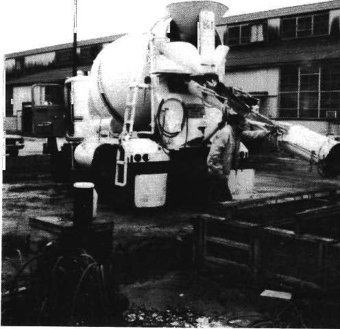
57 33 Figure 3.6 Casting
58
59 CHAPTER 4 ANCHOR NSTALLATON 4.1 ntroduction n this chapter, the installation procedures for the following types of anchors are discussed: 1. cast-in-place anchor bolts and embeds 2. retrofit anchors a. adhesive anchors (epoxy, polyester and vinylester) b. grouted anchors c. expansion anchors d. undercut anchors For cast-in-place anchors, placement in the formwork before casting is presented. For the retrofit anchors, hole drilling procedures, hole cleaning techniques, and anchor placement procedures are discussed. 4.2 Cast-n-Place Anchors Before casting, cast-in-place anchor bolts or embeds were placed in the forms as shown in Fig Anchors were held in the proper position and embedment length using 1 x 4 in. boards nailed across the top of the forms. These boards were removed after the concrete had set. 4.3 Adhesive Anchors {Epoxy, Polyester and Vinylester) n the following sections, anchor installation procedures for adhesive anchors are discussed for epoxy as well as polyester anchors. f no distinction is made, the sections apply to both types of adhesive anchors. When specific retrofit anchors are discussed in this report, the installation procedures of this section are referenced when possible, and any differences in the procedures of this section are then presented. 35


, holes for adhesive")
60 36 Figure 4.1 Placement of Cast-in-Place Anchors Threaded Rod Preparation. Threaded rods for all adhesive anchors were cut to the desired length and wire-brushed to remove any rust. All rods were then immersed in methyl-ethyl-ketone and wiped clean of any oily residue Hole Diameter. t has been suggested by several adhesive anchor manufacturers that to ensure sufficient anchor strength, the optimum hole diameter for adhesive anchors should be only 1/8 in. larger than the anchor diameter. Therefore, unless otherwise requested by the manufacturers (for example, Tests 8 and 24), holes for adhesive anchors were drilled with a 3/4 -in. bit for the 5/ 8-in. threaded
61 rods (see Table 3.1). A rotary hammer drill (Fig. 4.2) was used to drill all holes except those of Tests 21a and 21b, in which the manufacturer's compressed air drill was used (Fig. 4.3). The vertical holes created in the test specimens during casting (see subsection 3.5.3) served as pilot holes for drilling. Hole depths were measured using a tape measure after cleaning the hole (see below) Hole Preparation (Epoxy and Vinylester Anchors). At the beginning of the testing program, drilled-in holes were cleaned in accordance with each manufacturer's recommendations. Specimens 19a, 19b, and 21a pulled out, in spite of being installed in holes cleaned by merely blowing the dust from the holewith compressed air, as suggested by their manufacturers. Previous research by Luke 17 suggests that adhesive anchor strength can be increased by cleaning the holes with a stiff brush and an industrial vacuum cleaner. Luke states that a wire brush should be avoided since it will actually scar the concrete surface and create more dust. Luke's hole cleaning suggestions were therefore used on all other adhesive anchors of this study except Specimens 21d and 21e, which were used to examine the use of compressed air vs. brushing for hole cleaning (see subsection 6.2.8). A stiff bottle brush (Fig. 4.4), was rubbed in and out of the hole to remove as much of the dust as possible from the walls of the hole. An industrial vacuum cleaner with a 1/4 in. diameter nozzle removed the dust from the bottom of the hole (Fig. 4.5). This cleaning process took about 3 minutes per hole. Care was taken not to touch the walls of the hole with the fingers, so that skin oils would not contaminate the bonding surface Hole Preparation (Hand-Mixed Polyester Anchors). As mentioned in the previous subsection, the hole for Test 21a was cleaned with compressed air. This anchor exhibited bond failure at the adhesive-concrete interface, and showed concrete dust particles attached to the core of the adhesive, similar to that shown in Fig To determine the effects of different hole- cleaning methods on anchor strength for this type of adhesive, Tests 21c through 21f were conducted. Holes for Tests 21c and 21f were cleaned by the brushing and vacuuming technique described in subsection Holes for Tests 21d and 21e were cleaned by blowing the concrete dust from the hole with compressed air forced through a small diameter (1/4 in.) nozzle (Fig. 4. 7). Holes for all other polyester anchors (Tests 25, 36, and 43) were cleaned by brushing and vacuuming. 37


62 38 Figure 4.2 Rotary Hammer Drill Used to Drill Holes for Retrofit Anchors Figure 4.3 Air Drill Used to Drill Holes for Some Adhesive Anchors


63 39 Figure 4.4 Brush-cleaning of Hole with a Stiff Bottle Brush Figure 4.5 Vacuuming of Dust from Brushed Hole


64 40 Figure 4.6 Adhesive Anchor Failing in the Bond Between the Adhesive and Concrete Figure 4.7 Nozzle for Hole Cleaning with Compressed Air
65 Adhesive Preparation (Epoxy and Vinylester Anchors). The resin and catalyst components of the epoxies, supplied in separate containers, were proportioned as specified by the manufacturer, either by weight, by volume, or automatically during installation with a prepackaged device (Fig. 4.8). Weighing, when specified, was conducted using an electronic scale accurate to 0.01lb. Volume measurement, when specified, was conducted using styrofoam cups. Once proportioned, components were mixed in a 6 X 4 in. plastic cylinder, cut from a standard 6 x 12 in. cylinder mold. Low-viscosity epoxies were mixed using a "Jiffy Paint Mixer," turned by a rotary drill at rpm (Fig. 4.9) for 3-5 minutes. A higher mixing speed would have introduced air bubbles into the epoxy mixture. Higher-viscosity epoxies were mixed by hand using a paint stirrer. All epoxies were mixed until they showed uniform color Adhesive Preparation (Polyester Anchors). Polyester adhesives were supplied either as "ready-to-use" glass capsules, or as a two-component resin and catalyst system. With the two-component systems, a premeasured, prepackaged amount of the catalyst was added to one can of resin and mixed by hand for 3 to 5 minutes, using the threaded rod to be anchored. This type of mixing ensured that the threaded rod was well coated with adhesive before placement Placement of Anchors (Vertical nstallation). Anchor installation involved placing the adhesive into the hole and inserting the threaded rod. A small ball of linseed oil putty was first placed in the bottom of the drilled-in hole to keep the adhesive from leaking into the hole left for the head displacement instrumentation. Mixed adhesive was poured into the hole filling it about 1/3 full. Prepackaged epoxies were placed using a device similar to a caulking gun with a 10-in. length of tubing at the end. To prevent entrapping air inside the drilled hole, epoxy was placed from the bottom to the top of the hole, moving the gun outward until the hole was about 1/3 full. Threaded rods were wiped with the epoxy to coat the entire surface. The rods were slowly pushed into the hole while being rotated through several turns. Excess epoxy was removed from the concrete surface Placement of Epoxy and Vinylester Anchors (Horizontal and Overhead nstallations). All test specimens were drilled in a vertical position. They were


66 ~ '--.~. r ' - ' 1~&.., - t.;; ".; -~ ~~... Figure 4.8 Prepackaged and Premeasured Epoxy Device Figure 4.9 "Jiffy Paint Mixer" for Mixing Adhesives and Grout
. All epoxies tested were of the paste type, and were placed using a caulking gun with a 10 in.")
, was forced down into the hole with a rotary drill to break the capsule and mix the resin and catalyst components.")
67 43 either placed on their sides (for horizontal anchor installation) or supported upside down (for overhead anchor installation). Holes were cleaned with the blocks in the testing orientation (see subsection 4.3.3). All epoxies tested were of the paste type, and were placed using a caulking gun with a 10 in. length of tubing attached to the end. Placement was as described in subsection Figure 4.10 Polyester Adhesive in Glass Capsule Placement of Glass-Capsule Polyester Anchors. As described in subsection , linseed oil putty was placed into the drilled-in hole before insertion of the glass capsule. A specially threaded anchor rod with an angled tip (Fig. 4.10), was forced down into the hole with a rotary drill to break the capsule and mix the resin and catalyst components. Mixing and installation were completed when the anchor touched the bottom of the hole Curing (Epoxy and Vinylester Anchors: Horizontal, Vertical, and Overhead nstallations). At the beginning of the experimental program, Specimens 19a and 19b were cured under room conditions (about 80 F) for 24 hours as instructed by the manufacturer. After these anchors failed by pullout, curing time was changed to 7 days for all adhesive anchors except those of Tests 22a through 22e, which were
68 44 cured for 24 hours as requested by the manufacturer. All anchors were left in the installed position for the entire curing period Curing (Hand-Mixed Polyester Anchors). As requested by the manufacturers, polyester anchors were cured for 24 hours under room conditions. 4.4 Grouted Anchors Threaded Rod Preparation. Threaded rods were prepared as described in subsection Hole Diameter. Since the grout contains fine aggregate, development of proper anchor strength requires a larger diameter hole than that used for adhesive anchors. As instructed by the manufacturers, all grouted anchors were installed in 2-in. diameter holes drilled with a rotary hammer. A core drill was not used since it forms a smooth-walled hole, reducing the mechanical interlock between the grout and the wall surface Hole Preparation. Holes were cleaned as described in subsection After putty was inserted into the bottom of the holes (see subsection 4.3.7), the holes were flooded with water 24 hours prior to anchor installation to reduce the water loss from the grout into the surrounding concrete, and to ensure proper grout hydration Grout Preparation. Grout was packaged in 55 lb bags for proportioning by volume with water. The required volume of water for an entire 55lb bag was weighed on an electronic scale. Since only two anchors were installed at a time, the corresponding weights of grout and water were determined by proportion and mixed as described in subsection Placement of Anchors. The grout, being fluid, was poured directly into the holes, and the anchors were placed as discussed in subsection Curing. After initial set, moist rags were placed over the grout surface for 24 hours. Anchors were cured under room conditions as suggested by the manufacturers: 7 days for Tests 4, 35, and 42; and 28 days for Test 5.
.")

69 Expansion and Undercut Anchors Hole Diameter. All holes were drilled using a rotary hammer. Hole diameter and depth varied for each anchor brand due to differences in the dimensions of the anchor sleeve and housing (Fig ). Some undercut anchors (Tests 33, 39, and 48) required the use of a special undercutting bit (Fig. 4.11) to create the undercut bearing surface. Figure 4.11 Undercut Drill Bit for Undercut Anchors Hole Preparation. Since expansion anchors resist pullout by friction, and undercut anchors by friction and bearing, hole preparation is not as critical for expansion and undercut anchors as for the adhesive and grouted anchors. Nonetheless, all holes were cleaned as described in subsection Placement of Expansion Anchors. All expansion anchors were torque-controlled anchors (discussed in subsection 2.7.1). All anchors were gently tapped into the hole with a rubber hammer. A torque wrench, set in accordance with each manufacturer's specification (usually ft-lb ), was then used to expand the anchor against the sides of the hole.
70 Placement of Undercut Anchors. Undercut anchors were either torque-controlled (Tests 32) or hydraulic-controlled (Tests 33, 39, and 48). Torquecontrolled undercut anchors were placed into their holes and hammered with a special tool (supplied by the manufacturer) to create the undercutting action. As described in subsection 4.5.3, a torque wrench was used for final placement. Hydrauliccontrolled anchors were placed into their holes and expanded by tension applied to the anchor by a hydraulic ram.
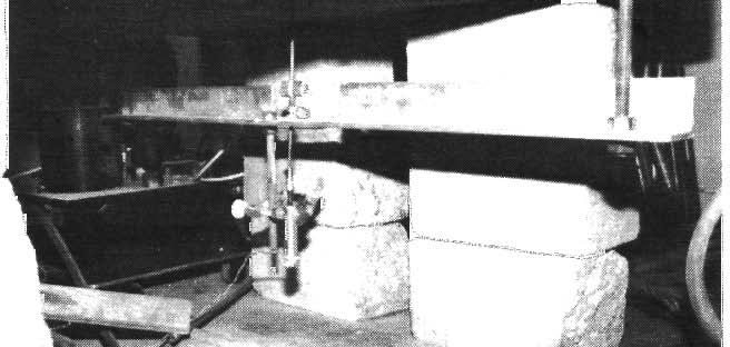
71 CHAPTER ntroduction TEST SETUP AND TEST PROCEDURE All tests were conducted on the testing floor of the Ferguson Structural Engineering Laboratory at the Balcones Research Center of The University of Texas at Austin. n this chapter, the loading system, instrumentation, data acquisition system, and testing procedure are discussed for each phase of the experimental program. 5.2 Test Setup Loading System. The loading system is shown in Figs. 5.1 and 5.2. Loads were applied to each anchor using a 100-ton capacity center-hole hydraulic ram and a reaction frame bearing on the concrete block. The reaction frame consisted of 2 structural steel channels (MC 6 x 18) placed back- to-hack on top of a steel ring. This ring, 27 in. across and 10 in. high, loaded the test specimen sufficiently far away from the anchor so that its anchor behavior was not significantly affected by local bearing stresses. The largest expected concrete cone pullout failure would fall within this ring. Load was applied to the anchor through a 1 in. diameter, 36 in. long high strength steel rod running through a load cell at the top of the ram, and connected to a hardened steel shoe at the anchor end (Fig. 5.2). The shoe, having a 3/4 in. hole in its base plate, was placed over the threaded portion (usually about 2 in.) of the anchor protruding from the surface of the concrete. A washer and a heavy hex nut on the anchor threads secured the shoe to the anchor. The hydraulic loading system is shown schematically in Fig Hydraulic fluid was delivered to the ram by a 3-gpm pump, a line tamer, and a servovalve. The servovalve was controlled by a Pegasus 5100 Series Mini Servocontroller Tension Tests. During the static tension tests, the servocontroller was operated manually and under load control. However, after a few tests, it was realized that anchor load-displacement behavior beyond ultimate load would be useful, and the system was changed to displacement control. 47


72 48 Figure 5.1 Loading System Fatigue Tests. Fatigue tests were run under load control. Sinusoidal fatigue loads were applied using the internal function generator in the Pegasus Servocontroller unit mpact Tests. mpact load tests were run under load control. Triangular pulses were input to the servocontroller by an Exact 336 Function Generator.
73 Load Cell 49 Hydraulic Ram Steel Plate ~ Back-to-Sack Channels Concrete Blo k Reaction Ring Loading Shoe Figure 5.2 Schematic Drawing of Loading System Hydraulic Pump Line Tamer Hydraulic Ram Figure 5.3 Schematic Drawing of Hydraulic System
74 nstrumentation Applied Load. Loads applied to the anchors were measured with a Strainsert 50 kip fatigue-rated load cell. The load cell was placed in compression between the top of the ram and the nut on the rod connected to the shoe and the anchor (Figs. 5.1 and 5.2) Displacement Measurements. Using 2-in.linear potentiometers, displacements were measured in three locations (Figs. 5.4 and 5.5): 1. the loaded end of the anchor shank 2. the concrete surface near the anchor shank 3. the anchor head Head Displacement. Anchor head displacement was determined by measuring the movement of a 1/8 in. diameter steel rod resting against the anchor head, and inserted from beneath the concrete specimen into the hole created for this purpose (see subsection 3.5.3). Two 3-in. aluminum channels were bolted on either side of the concrete specimen (Fig. 5.6), and a smaller aluminum channel was attached below the concrete specimen. The steel measurement rod passed through a small hole in the smaller channel and was held in compression against the head of the anchor by a spring (Fig. 5.4). Anchor slip caused upward movement of the linear potentiometer attached to the end of the steel rod. The rod was thick enough so that it would not buckle inside the hole under the spring compression. 5.4 Data Acquisition System Static and Fatigue Tests. The load and the three displacements were recorded by a Hewlett-Packard data acquisition system. They were converted to engineering units, stored, and plotted using a microcomputer mpact Tests. Two Hewlett-Packard 7090 Plotters recorded the load and three displacements. These data were transferred to a microcomputer and converted to engineering units using a spreadsheet program.


75 Figure 5.4 Location of Displacement Measurements 51
76 52 Applied Load Concrete Displacement Stiff Rod Head Displacement Figure 5.5 Schematic Drawing of Location of Displacement Measurements Load Time Figure 5.6 Aluminum Channels to Hold Displacement Measurement nstrumentation

 were stopped due to excessive slip in the anchor.")


77 Test Procedures Static Tests. Loads were applied in accordance with ASTM E Loading intervals of 2 kips were used until the load reached about 70% of its expected maximum value. After that point, 1 kip intervals were used until failure occurred. However, some tests (Tests 4b, 13, 18, 19, 21c, 22b through 22e, 27, 28b, 31, and 33a) were stopped due to excessive slip in the anchor. Load and displacement readings were taken at each load interval Fatigue Tests. For each anchor tested in fatigue, a static load test was performed as in subsection to a maximum load of 0.60/y A 5, corresponding to a service load level. The anchors were then loaded in fatigue for 1 million cycles at approximately 17 Hz, using a stress range of 7 ksi to a maximum stress of 0.60 /y, just below the endurance limit of the steel. This stress range was chosen to study behavior of the load transfer mechanisms to the concrete, not the anchor steel strength, under fatigue loading. After application of the fatigue load, a static load test to failure was performed. Load and displacement measurements were taken during each static load test at the intervals described in the previous subsection. Figure 5. 7 mpact Loading Function
78 mpact Tests. Loads were applied to the anchors using a triangular pulse approximately 0.25 seconds long (Fig. 5. 7). Three pulses were applied to the anchor at a load of 0.60/ 11 A. During ea.ch pulse, 1000 load-displacement measurements were recorded by the Hewlett-Packard 7090 Plotters. H the anchor behaved satisfactorily, 3 pulses at 0.80/ 11 A 11 and 3 pulses at yield (1.0 / 11 A.) were conducted, and load-displacement data were recorded during each pulse.
79 CHAPTER 6 TYPCAL RESULTS 6.1 ntroduction n this chapter, typical load-deflection results for the various anchors are presented. Results for static and fatigue tests are organized according to modes of behavior. Results for impact tests are organized according to stiffness characteristics. Results for anchors with similar load- deflection behavior are presented in tabular form within each typical result category. Results of tests related to the effects of orientation and hole cleaning technique for adhesive anchors are presented in tabular form according to modes of behavior. Load-deflection plots for all remaining tests are presented in Appendix 1. Organization of the results using these performance criteria allows for direct comparison between different anchor types under static, fatigue, and impact loads, and facilitates the description of behavior (Chapters 7 and 8) using generally applicable principles which are independent of anchor brand. Results of the tests presented in this thesis should be interpreted under the following conditions: a. Results are strictly valid only for the anchors tested in this study and the conditions under which they were studied. b. Results of these retrofit anchor tests could be modified as a result of changes in anchor specifications, concrete type, installation procedures, or testing environment. c. Results should not be interpreted as applying to all anchors of a given type. That is, results should not be construed to imply that all anchors of a given type are better than all anchors of another type. d. Results should not be construed as an endorsement of any particular anchor type or anchor brand. e. Results do not include the effects of environmental exposure. 55
: Yield and fracture of the anchor shank, without anchor slip (cast-in-place, adhesive, and grouted anchors) 2. Mode 2 Behavior (Figs. 6.3 and 6.")
: Failure of the bond between the adhesive and concrete (adhesive anchors) 5. Mode 5 Behavior (Fig. 6.7): Failure of the bond between the anchoring material and anchor steel (adhesive and grouted anchors) Figure 6.")
80 Static Tests General Observations. Anchors under static loads exhibited the following Modes of Behavior (Figs. 2.3 and 2. 7): 1. Mode 1 Behavior (Figs. 6.1 and 6.2): Yield and fracture of the anchor shank, without anchor slip (cast-in-place, adhesive, and grouted anchors) 2. Mode 2 Behavior (Figs. 6.3 and 6.4): Yield and fracture of the anchor shank, accompanied by anchor slip (expansion, undercut, and adhesive anchors) 3. Mode 3 Behavior (Fig. 6.5): Anchor pullout (expansion and undercut anchors) 4. Mode 4 Behavior (Fig. 6.6): Failure of the bond between the adhesive and concrete (adhesive anchors) 5. Mode 5 Behavior (Fig. 6.7): Failure of the bond between the anchoring material and anchor steel (adhesive and grouted anchors) Figure 6.1 Mode 1 Behavior (Shank Fracture, No Slip) for Cast- in-place Anchors

 for Adhesive")
81 Figure 6.2 Mode 1 Behavior (Shank Fracture, No Slip) for Adhesive and Grouted Anchors 57
")
")
82 58 res -;a3~ H-LT Figure 6.3 Mode 2 Behavior (Shank Fracture, Some Slip) for Expansion and Undercut Anchors Figure 6.4 Mode 2 Behavior (Shank Fracture, Some Slip) for Adhesive Anchors
 for")

83 59 Figure 6.5 Mode 3 Behavior (Pullout Failure) for Expansion and Undercut Anchors Figure 6.6 Mode 4 Behavior (Failure of the Bond Between the Adhesive and the Concrete) for Adhesive Anchors
 for Adhesive and Grouted Anchors Embedment depths were sufficient so that no anchor failed by the formation of a complete")

84 60 Figure 6.7 Mode 5 Behavior (Failure of the Bond Between the Adhesive Anchor Steel) for Adhesive and Grouted Anchors Embedment depths were sufficient so that no anchor failed by the formation of a complete concrete cone (Fig. 2.3). Before failure, some adhesive and grouted anchors exhibited spalling of the concrete around the anchor shank (Fig. 2.10). The depth of this spall depended on the anchor type and the mode of behavior and is discussed in Chapter 7. n this chapter and throughout this study, slip is defined as the displacement of the anchor head. Elongation is defined as increase in anchor length, calculated as the difference between the shank and head displacements Typical Test Results For Mode 1 Behavior: Shank Fracture, No Slip (Cast-in-Place, Adhesive, and Grouted Anchors). Anchors exhibiting shank fracture without slip are listed in Table 6.1, and typical load-deflection behavior is shown in Figs. 6.8 and 6.9. As described in subsection and shown in all load-deflection plots in this study, the following measurements were taken during testing: applied load, anchor shank displacement, concrete displacement near the anchor shank, and anchor head displacement.
85 61 Mode 1 Behavior: Table 6.1 Shank Fracture Without Anchor Slip A) Caat-ia-Place Aachon 'l'eilt Bolt Embedmeat Maximum Number Streagth 1 Leagth (kai) (a.) 1a b c a b c a b Load (ki.-) :.u.o B) Adhesive AachoN 'l'eilt Bolt Embedmeat Maximum Spall Number Streagth 1 Leagih Load Depth 2 (kai) (ia.) (ki.-) (ill.) 8a b a b a b a b lta Tb e a b Spall Diametr (ill.) Maximum Eloagatioa (ia.) C) Grouted AachoN 'l'eilt Bolt Embedmeat Maximum Spall Number Streagth 1 Leogih Load Depth (kai) (a.) (ki.-) (ia.) 4a a b Spall Diameter (io.) - - Maximum Eloogatioa (ill.) Note: 1 Mioimum specified ultimate teasile streagth 2 "-" iadicatea ao spall occurred
86 62 V 0... ~ < g 10 0 Figure 6.8 V 0... ~ < 9 Figure 6.9 ) J TEST 2a fu= 150 ksi /' CAST-N-PLACE BOLT le=7" FALURE MODE: STEEL 0 SHANK DSPLACEMENT 6 CONCRETE DSPLACEMENT 0 HEAD DSPLACEMENT DSPLACEMENTS. N. ~ ( 10 J 0 0 Typical Load-Deflection Behavior for Cast-in Place Headed Anchors Exhibiting Mode 1 Behavior (Shank Fracture, No Slip) TEST 17b SKADUR 32 fu=150 ksl le=8" FALURE MODE: STEEL, ' _a! 0 SHANK DSPLACEMENT 6 CONCRETE DSPLACEMENT 0 HEAD DSPLACEMENT - ~ i DSPLACEMENTS, N. Typical Load-Deflection Behavior for Adhesive and Grouted Anchors Exhibiting Mode 1 Behavior (Shank Fracture, No Slip) i - i.6 i
87 63 Since Test 2a (Fig. 6.8) and others (Tests 1 and 19) were conducted under load control, load-deflection behavior beyond ultimate was not obtained. A complete load-deflection plot (including yielding ofthe steel), obtained under deflection control is shown in Fig Characteristics of shank fracture and no slip include yielding and fracture of the anchor shank, no slip of the anchor head, and occasional slight spalling of the concrete around the anchor shank for adhesive anchors (Tests 15a, 15b, and 17a). The spall depths were less than 0.5 in. (Fig. 6.2). Any differences among load-deflection behaviors (for example, greater shank elongations) are due mainly to differences in steel properties Typical Test Results For Mode 2 Behavior: Shank Fracture, Anchor Slip (Adhesive, Expansion, and Undercut Anchors). Expansion and undercut anchors failing by steel fracture are listed in Table 6.2. As illustrated in the typical load-deflection plot of Fig. 6.10, the anchors had typically slipped about 0.14 in. when the shank fractured. Undercut anchors usually slipped less, with values ranging from 0.06 to 0.1 in. (Table 6.2). Slip began when the applied load equaled the anchor preload, about 11 kips for expansion anchors and about 19 kips for undercut anchors, as discussed in subsection Slip continued only with increased load, and stopped when the maximum load was reached. No spalling or cracking of the concrete was observed. Several adhesive anchors began to slip before fracture of the anchor shank (Table 6.2 and Fig. 6.11). For Tests 21a through 21f (Appendix 1), head displacement instrumentation did not operate properly. For Tests 21c through 21f, no head displacement data were taken. However, since the shank displacement was much greater than for adhesive anchors exhibiting Mode 1 Behavior and a concrete spall formed around the anchor shank, these tests are believed to have exhibited Mode 2 Behavior. As shown in Fig. 6.4, slip was accompanied by spalling to a depth of about 0.75 in., intermediate between those depths measured for Mode 1 and Mode 2 Behaviors Typical Test Results For Mode 3 Behavior: Anchor Pull out (Expansion and Undercut Anchors). A typical load-deflection plot for anchor pullout is shown in Fig Results of the other expansion and undercut anchor tests are listed in Table 6.3. Anchors failing in this manner typically reached and maintained
88 64 TEST 33c DRLLCO MB625 fu-150 ksl le-7.5" 0 SHANK DSPLACEMENT 6 CONCRETE DSPLACEMENT 0 HEAD DSPLACEMENT ~------~----~~ ~ O ~------r-----~ ~ 0.2..e.a 1.2 OSPLACE..CENTS, N. Figure 6.10 Typical Load-Defiection Behavior for Expansion and Undercut Anchors Exhibiting Mode 2 Behavior (Shank Fracture, Some Slip) TEST 21 e KELKEN-GOLD, NC. fu l<si le-7" FALURE MODE: STEEL (/') a. S2 ~ / 0 SHANK DSPLACEMENT 6 CONCRETE DSPLACE~NT i._.... '-...! ~! v l e.a 1.2 DSPLACEMENTS, N. Figure 6.11 Typical Load-Defiection Behavior for Adhesive Anchors Exhibiting Mode 2 Behavior (Shank Fracture, Some Slip) ~
89 65 Table 6.2 Mode 2 Behavior: Shank Fracture with Some Slip Al Expaoaion Anchon Test Doli Embed men\ Maximum Number Strength 1 Length Load (lati) (in.) (ldpa) 28a c d a b Maximum Maximum Elongation Slip (in.) (in.) B) U ndercui Anchon Tesi Doli Embed men\ Maximum Maximum Maximum Number Sirengih 1 Length Load Elongation Slip (kai) (in.) (ldpa) (in.) (in.) 32a b b c d C) Adheaive Anchon Teat Doli Embedment Maximum Spall Number Sirengih 1 Length Load Depth (bi) (in.) (kipa) (ln.) 18a b d e f Spall Elongtation 2 Diameter (in.) (in.) Slip (ln.) N/A N/A N/A Noies: 1 Minimum apecifted ulilmaie tenllile atrength 2 Elongaiioa of anchor ateel at ateel failure 3 'lbtal diaplacement including alip - no individual alip wu meuured
90 66 a maximum load of about 2/3 of the shank fracture load (22 kips, as observed in subsection 6.2.3). Typically, the anchor head then displaced the same as the anchor shank (Fig. 6.12). This slip was accompanied by a sharp "popping" noise. Tests were terminated when shank and head displacements increased with no increase in load. No spalling or cracking of the concrete around the anchor shank was observed. 40 fu==150 kai TEST 27b UNFAST ND. ie=9" FALURE t.aooe: BOLT SLP ~~------~ ~ ~D--s-H-~-K--D 11 s-p-la_c_e_me_n_t 1 [ ,~. l:j. CONCRETE DSPLACEMENT ~ ' 0 HEAD DSPLACEMENT , r- [ 10~----~----~~----~~ T----~ i.2.4.e.e 1.2 DSPLACEt.AENTS, N. Figure 6.12 Typical Load-Deflection Behavior for Expansion and Undercut Anchors Exhibiting Mode 3 Behavior (Anchor Pullout) Typical Test Results For Mode 4 Behavior: Adhesive-Concrete Bond Failure (Adhesive Anchors). As listed in Table 6.4, only adhesive anchors (both epoxy and polyester) failed in the bond between the adhesive and the concrete (Fig. 2. 7). Maximum loads before bond failure ranged from about 10 kips to about 31 kips: the latter corresponds to the shank fracture load (Figs and 6.14). Anchors apparently resisted the load up to a critical level of maximum bond stress. Beyond that load level, the anchor and adhesive began to slip out as a unit, as shown graphically by the equal slopes of the shank and head displacement curves
91 67 Table 6.3 Mode 3 Behavior: Anchor Pullout A) Expansion Anchors Test Bolt Embedment Maximum:~ Number Strength 1 Length Load (ksi) (in.) (kips) 27a b b a b c B) Undercut Anchors Test Bolt Embedment Maximuml Number Strength 1 Length Load (ksi) (in.) (kips) 33a Elongation;, (in.) Elongation 3 (in.) 0.02 Notes: 1 Minimum specified ultimate tensile strength 2 Maximum load obtained before test was terminated 3 Elongation of anchor steel at point of first slip 4 Anchor was improperly installed (Figs and 6.14). Little or no anchor slip was detected before bond failure. Af ter bond failure, residual anchor strength was due to mechanical interlock between the adhesive and the concrete. Spalls from 1 to 2 in. deep (considerably deeper than those accompanying shank fracture) usually formed around the anchor shank (Fig. 6.6) at bond failure Typical Test Results For Mode 5 Behavior: Anchoring Material - Steel Bond Failure (Adhesive and Grouted Anchors). n Table 6.5 are listed the adhesive and grouted anchors exhibiting the typicalload deflection behavior shown in Fig Maximum anchor tensile capacity was reached at sudden, audible
92 68 40 TEST 18b WL-COR AP990 fu=150 ksl le=8" FALURE MODE: EPOXY CORE JO+~ r------~ SHANK ::J Si?LACEMENT 6 CONCRETE DSPLACEMENT 0 HEAD DSPLACEMENT 1 '! to 0 vr "' _l J.4.5 DSPLACEMENTS. N..6 Figure 6.13 Typical Loa.d Deftection Behavior for Adhesive Anchors Exhibiting Mode 4 Behavior (Failure of the Adhesive.Concrete Bond) TEST 13b RESCON R626 fu= 150 ksl le-8" F AlLURE MODE: EPOXY CORE 40T ~----~,-----~ r r------, 0 SHANK DSPLACEMENT 6 CONCRETE DSPLACEMENT 0 HEAD DSPLACEMENT ~----~r-----~ r------~.1.2.J DSPLACEMENTS, N. Figure 6.14 Typical Loa.d Deftection Behavior for Adhesive Anchors Exhibiting Mode 4 Behavior (Failure of the Adhesive.Concrete Bond
93 69 Table 6.4 Adhesive Anchors Under Static Loads Failing in the Bond Between the Adhesive and the Concrete Test Bolt Embedment Maximum Spall Spall Number Strength 1 Length Load Depth Diameter (kai) (in.) (kips) (in.) (in.) 13a b & 18a 1& & b 1& o.& lla 1& &.8 0.1& 19b 1& & 19c 1& & lid 1& a &.0 1& c 5 1& & 24a 60 & b 60 & J & & 1 Elongation 1 (in.) & N/A NfA 0.06 Notes: 1 Minimum Specified Ultimate Tenaile Strength 2 Elongation of anchor ateel when t t wu atopped 3 Anchor improperly inatalled 4 Drill may have operated improperly 5 Hole drilled, not wire-bruahed (manufacturer' inatructiona) bond failure, not preceded by any anchor slip. Residual anchor strength was due to mechanical interlock between the steel and the anchoring material. Spalls formed around the anchor shank at bond failure. Their depths ranged from 2.5 in. at a in. embedment, to 1.0 in. at a 7.5-in. embedment Horizontal and Overhead Adhesive nstallations. Modes of behavior of the horizontal and overhead tests are listed in Table 6.6. Failure occurred either by shank fracture (subsection 6.2.2) or failure of the adhesive- concrete bond (subsection 6.2.5).
94 70 Mode 5 Behavior: Table 6.5 Adhesive-Steel Bond Failure A) Adhesive Anchors Test Boh Embedment Maximum Spall Spall Elongation:.: Number Strength 1 Length Load Depth Diameter (ksi) (in.) (kips) (in.) (in.) (in.) 22a b c d B) Grouted Anchors Test. Boli Embedment Maximum Spall Spall Elonga.tion 2 Number St.rength 1 Length Load Depth Diameter (ksi) (in.) (kips) (in.) (in.) (in.) 4b Notes: 1 Minimum specified ultimate tensile strength 2 Elongation of uchor steel a.t point or first Blip Effects of Brushed vs. Air-Blown Holes. The adhesive anchors listed in Table 6. 7 were installed with the same adhesive in holes cleaned by brushing and vacuuming, or by compressed air (discussed in subsection 4.3.3). Steel fracture with some slip (see Section 6.2.3) was the primary mode of behavior. Only one Specimen (2lc), installed in a brushed and vacuumed hole, failed in the bond between the adhesive and the concrete (see subsection 6.2.5). The implications of these results are discussed in Chapter Fatigue Tests General Observations. Anchors were loaded statically to about 0.6 /y A. before application of the high-cycle fatigue load (see subsection 5.5.2). After 1 million cycles, anchors were tested statically to failure, to assess their change in stiffness due to the fatigue loading. Because the fatigue and static loads were
95 71 TEST 4b U.S. GROUT NBEC fu= 150 ksl le=8" FALURE t.aode: GROUT-STEEL BONO 0 SHANK DSPLACEMENT 6 CONCRETE DSPLACEMENT 0 HEAD DSPLACEMENT o ~ 0.1 ~.J..5.6 DSPLACEt.4ENTS, N. Figure 6.15 Typical Load-De:ftection Behavior for Adhesive and Grouted Anchors Exhibiting Mode 5 Behavior (Failure of the Adhesive-Anchor Stel Bond) applied under load control, no descending-branch behavior could be observed (see subsection 6.2.2). n the load-de:ftection plots of this section and of Appendix 1, anchor behavior is compared under the static loads applied before and after the fatigue loading. No measurements were taken during fatigue loading. No anchor failure occurred during the first static loading, nor during the subsequent fatigue loading. As detailed in Table 6.8, a.ll failures occurred during the final static load test, and had the following characteristics: 1. Mode 6 Behavior: Shank fracture with no slip or loss of anchor stiffness (grouted and adhesive anchors) 2. Mode 7 Behavior: Shank fracture with no slip and some loss of anchor stiffness (cast-in-place anchors) 3. Mode 8 Behavior: Shank fracture with some slip (adhesive, expansion, and undercut anchors)
96 72 Table 6.6 Adhesive Anchors nstalled in Horizontal and Overhead Positions - A) Horizontal Test Anchor Embedment Mode of Behavior Number Strength Length (ksi) (in.) 12a :Shank Fracture 12b :Shank Fracture 18a :Adhesive-Concrete Bond 18b :Adhesive-Concrete Bond B) Overhead Test Anchor Embedment Mode of Behavior Number Strength Length (ksi) (in.) 13a :Adhesive-Concrete Bond 13b :Adhesive-Concrete Bond 15a :Shank Fracture 15b :Shank Fracture Table 6.7 Adhesive Anchor Tests nvolving the Effects of Brushed vs. Air-Blown Holes Test Anchor Embedment Type of Mode of Behavior Number Strength Length Cleaning (ksi) (in.) 21c Brushed 4:Adhesive-Concrete Bond 21d Air-Blown 4:Shank Fracture w /Slip 21e Air-Blown 2:Shank Fracture w /Slip 21f Brushed 2:Shank Fracture w /Slip
97 73 Table 6.8 Anchors Tested Under Fatigue Loads and Related Parameters Test Number 34a 34b 35a 35b 36a 36b 37a 37b 38a 38b 39a 39b Anchor Anchor Embedment Maximum Failure Type Strength 1 Length Load Mode 2 (ksi) (in.) (kips) CP :SF CP :SF Grouted :Grout-Steel Bond Grouted :SF Adhesive :SF w/slip Adhesive :SF w/slip Adhesive :SF Adhesive :SF Expansion :SF w/slip Expansion :SF w/slip Undercut :SF w/slip Undercut :SF w/slip Notes: 1 Minimum specified ultimate tensile strength 2 Failure during second static test of fatigue sequence; SF : Shank fracture 3 Cast-in-place bolt 4. Mode 9 Behavior: Failure of the grout-steel bond (occurred in only 1 grouted anchor) Typical Test Results for Mode 6 Behavior: Shank Fracture, No Slip, No Loss of Anchor Stiffness (Grouted and Adhesive Anchors). Shank fracture with no slip or loss of anchor stiffness, shown in Fig. 6.16, was observed only for some grouted and adhesive anchors (see Table 6.8). As shown in Fig. 6.16, anchor stiffness appears to he about the same before and after fatigue loading, with no measured anchor slip. No spalling occurred, hut slight cracks were observed in the
98 ~ ~ 10 ~ TEST 35b U.S. GROUT fu-150 kal le-8" FALURE r..ode: STEEL! n. (] SHANK DSPLACEMENT BEFORE FATGUE LOAD - ~ CONCRETE DSPLACEMENT BEFORE FATGUE LOAD ~ HEAD DSPLACEMENT BEFORE FATGUE LOAD SHANK DSPLACEMENT AFTER FATGUE LOAD ~ CONCRETE DSPLACEMENT AFTER FATGUE LOAD 4l HEAD DSPLACEMENT AFTER FATGUE LOAD s DSPLACEWENTS, N. Figure 6.16 Typical Load-Deflection Behavior for Adhesive and Grouted Anchors Exhibiting Mode 6 Behavior (Shank Fracture, No Slip, No Loss of Anchor Stiffness) concrete around the anchor shank at failure on some tests (Tests 35). Such spalling was evidenced by the measured concrete displacement illustrated in Fig Typical Test Results for Mode 7 Behavior: Shank Fracture, No Slip, Some Loss of Anchor Stiffness (Cast-in-Place Anchors). Cast-in-place anchor bolts (Table 6.8) lost some stiffness due to fatigue loading as illustrated by the shank displacements of Fig No anchor slip or concrete spalling was observed Typical Test Results for Mode 8 Behavior: Shank Fracture, Some Slip, Some Loss of Anchor Stiffness (Adhesive, Expansion, and Undercut Anchors). For adhesive anchors, a typical load-deflection plot for shank fracture with some anchor slip is shown in Fig Anchor stiffness is unaffected by fatigue loading below a steel stress range of 0.60/ 11, corresponding to a load of about 14.3 kips. Anchor slip began beyond this load level. However, the anchor then resisted more load, until the steel fractured. Spa.lls with depths between 1 inch and 1.5 inches formed in the concrete around the anchor shank.
99 75 ll Q. S2 TEST 34b CAST-N-PLACE BOLT fu-150 ksl le-7" FALURE MODE: STEEL ~ , r::::.._ j ---t ,1' SHANK DSPLACEMENT BEFORE FATGUE LOAD Sl ~ CONCRETE DSPLACEMENT BEFORE FATGUE LOAD q_. () HEAD DSPLACEMENT BEFORE FATGUE LOAD SHANK DSPLACEMENT AFTER FATGUE LOAD ~ CONCRETE DSPLACEMENT AFTER FATGUE LOAD 10 lf-+-,c...-.j-.- HEAD DSPLACEMENT AFTER FATGUE LOAD ~---~------~---~---~ 0 t s.e DSPLACEWENTS, N. _j Figure 6.17 Typical Load-Deflection Behavior for Cast-in-Place Headed Anchors Exhibiting Mode 7 Behavior (Shank Fracture, No Slip, Some Loss of Anchor Stiffness As illustrated in Fig. 6.19, expansion anchors were less stiff, as shown by the shank displacement curves, after than before fatigue loading. Anchor slip began near the preload value of about 11 kips. Slip ranged from about 0.18 to about 0.26 in. at failure, slightly greater than the values recorded during the original static tests (see subsection ). As shown in Fig. 6.20, undercut anchor stiffness was unaffected by fatigue loading. During the final static tests of the fatigue testing sequence, undercut anchors behaved as they had in the original static tests (see subsection 6.2.3). Slip at failure was about 0.1 in., and the concrete around the anchor shank did not spall Typical Test Results for Mode 9 Behavior: Failure of the Grout Steel Bond, Loss of Anchor Stiffness (Grouted Anchors). Grout-steel bond failure occurred in Test 35a only. t appears from the load-deflection plot shown in Fig that anchor stiffness slightly increased after fatigue loading. This apparent anomaly is probably due to small errors in displacement measurement, since the shank a.pd
100 76 TEST 36b KELKEN-GOLD, NC. fu=150 k l le-7" FALURE li.fooe: STEEL ~ ~ 52 J SHANK DSPLACEMENT BEFORE FATGUE LOAD 20 ifl il. CONCRETE DSPLACEMENT BEFORE FATGUE LOAD 0 Q HEAD DSPLACEMENT BEFORE FATGUE LOAD ~ SHANK DSPLACEMENT AFTER FATGUE LOAD - A CONCRETE DSPLACEMENT AFTER FATGUE LOAD 4l HEAD DSPLACEMENT AFTER FATGUE LOAD t--J 0.1 ~ ~ OSPLACE.fENTS, N. Figure 6.18 Typical Load-Deflection Behavior for Adhesive Anchors Exhibiting Mode 8 Behavior (Shank Fracture, Some Slip, Some Loss of Anchor Stiffness) the head displacements are both small. The stiffnesses are believed to be about equal (see subsection 6.3.2). The sudden failure of the bond between the grout and the steel was accompanied by a "popping" sound, similar to the behavior observed in the original static tests (see subsection 6.2.6). No slip of the anchor was detected before bond failure. A spall, 2 in. deep, formed in the concrete around the anchor shank. 6.4 mpact Tests General Observations. As discussed in subsection 5.5.3, impact loads were idealized by a symmetrical triangular pulse 0.25 seconds long. Maximum tensile loads were applied at three load levels, corresponding to steel stresses of 0.60/ 11, 0.80 f 11, or 1.0 f 11 Three pulses were conducted at each load level.
101 TEST 38a HLT HSL ANCHOR fu-100 kat le-6" falure.n ~ODE: STEEL ~ ' JO +----t-----f--- -r------'-----l 77 Figure 6.19 [J j SHANK DSPLACEMENT BEFORE FATGUE LOAD ~ CONCRETE DSPLACEMENT BEFORE FATGUE LOAD 10 i'irlr:f Q HEAD DSPLACEMENT BEFORE FATGUE LOAD j SHANK DSPLACEMENT AFTER FATGUE LOAD ~ CONCRETE DSPLACEMENT AFTER FATGUE LOAD 4l HEAD DSPLACEMENT AFTER FATGUE LOAD O L l :S.4.~. DSPLACE~ENTS, N. Typical Load-Deflection Behavior for Expansion Anchors Exhibiting Mode 8 Behavior (Shank Fracture, Some Slip, Some Loss of Anchor Stiffness) TEST 39b DRLLCO M8625 fu-150 k l le-7.5" falure ~ODE: STEEL ~!.1 l ~-- j_ t- ---r----i i. i [J jshank DSP~ACEMENT BE~ORE FATG~ LOAD ~ ~ CONCRETE DSPLACEMENT BEFORE FATGUE LOAD () HEAD DSPLACEMENT BEFORE FATGUE LOAD SHANK DSPLACEMENT AFTER FATGUE LOAD ~ CONCRETE DSPLACEMENT AFTER FATGUE LOAD 4l HEAD DSPLACEMENT AFTER FATGUE LOAD l Figure ! [.-l.4.1.a DSPLACEWENTS, N. Typical Load-Deflection Behavior for Undercut Anchors Exhibiting Mode 8 Behavior (Shank Fracture, Some Slip, Some Loss of Anchor Stiffness)
102 78 Figure 6.21 fu-150 ksl TEST 35a U.S. GROUT NBEC le=8" FALURE UODE: GROUT-STEEL BOND 40~------, ,------~ ~------~ JO SHANK DSPLACEMENT BEFORE FATGUE LOAD ~ CONCRETE DSPLACEMENT BEFORE FATGUE LOAD ~ Q HEAD DSPLACEMENT BEFORE FATGUE LOAD ~ SHANK DSPLACEMENT AFTER FATGUE LOAD i: HEAD DSPLACEMENT AFTER FATGUE LOAD ~ ~ c 10+--f:j]~- 0 ~ L ~ ~.4.5.1!1 DSPLACEUENTS, N. Typical Load-Deflection Behavior for Grouted Anchors Exhibiting Mode 9 Behavior (Failure of the Grout-Steel Bond) Anchor behavior is described according to the maximum load and secant stiffness (Fig. 6.22) at each pulse. As illustrated in Fig. 6.22, displacement measurement equipment was only sensitive to about in., while load measurement equipment was sensitive to within 0.1 kips. As a result, small changes in applied load often produced no apparent change in displacement, resulting in the jagged appearance of the load-deflection curves. Secant stiffness is represented by the slope of the line passing through the origin of the load-shank displacement curve to the maximum shank displacement (Fig. 6.22). Slip is defined as the measured displacement of the anchor head. All anchors (Table 6.9) resisted the three levels of impact load without exhibiting shank fracture or pullout. The following modes of behavior were observed under impact loads: 1. Mode 10 Behavior: No degradation of anchor stiffness, and no anchor slip (cast-in-place, adhesive, and grouted anchors) - ~
103 79 TEST 41 a CAST-N-PLACE BOLT fu-150 ksi le 7" 25T , 20 (/) 15 a. 52 SECANT STFFNESS DSPLACEMENTS. N..oe.01 Figure 6.22 Secant Anchor Stiffness for Anchors Under mpact Loads 2. Mode 11 Behavior: Degradation of anchor stiffness accompanied by anchor slip (adhesive, expansion, and undercut anchors) Typical Test Results for Mode 10 Behavior: No Degradation of An char Stiffness, No Anchor Slip (Cast in Place, Adhesive, and Grouted Anchors). Anchors that did not slip during impact testing are listed in Table 6.9. A typical plot of secant stiffnesses for this mode of behavior is shown in Fig Secant stiffness is plotted at the first and third pulses of each load level. Stiffnesses were about the same at all load levels. Maximum loads were the same at the first and third pulses at each load level. No cracking was observed in the concrete surrounding the anchor shank Typical Test Results for Mode 11 Behavior: Degradation of Anchor Stiffness, Some Anchor Slip (Adhesive, Expansion, and Undercut Anchors). As illus trated in Fig. 6.24, adhesive anchors with slip typically behaved like adhesive anchors with no slip (see subsection 6.4.2) during the first load level. Secant stiffnesses and maximum loads were the same at pulses "A" and "C." Slip typically began at the first pulse ofload level 2, corresponding to 0.80 A. / 11, or about 19 kips. Slip occurred
104 80 Table 6.9 Anchors Tested Under mpact Loads and Related Parameters Test Anchor Anchor Embedment Anchor Number Type Strength 1 Length Slip (bi) (in.) 4la Cut-in-Place No 42a Grouted No 42b Grouted No 43a Adhesive Yes 43b Adhesive Yes 44a Adhesive No 44b Adhesive No 47a Expansion Yes 47b Expansion Yes 48a Undercut Yes 48b Undercut Yes Note: 1 Minimum specified ultimate tensile strength mostly during the first pulse of loa.d levels 2 and 3. As shown in Fig. 6.24, secant stiffness was less at the first pulse than at the third pulse for loa.d levels 2 and 3. Maximum loads increased between the first and third pulses at loa.d levels 2 and 3. Concrete around the anchor shank cracked slightly when the anchor first slipped. Expansion anchors typically ha.d about the same secant stiffnesses (Fig. 6.25) and did not slip during loa.d level 1, a loa.d slightly greater than the anchor preload of about 11 kips. Slip began at the first pulse of loa.d level 2 (about 14.8 kips) and generally remained constant at each load level thereafter. Slip increased and the secant stiffness decreased between the third pulse of loa.d levels 1 and 2 and the first pulse of loa.d levels 2 and 3 (Fig. 6.25). The maximum loa.d remained constant for successive pulses at loa.d levels 2 and 3, and increased slightly for successive pulses at load level 3. Cracks did not form in the concrete around the anchor shank.
105 81 25 G, TEST 42b U.S. GROUT NBEC fu- 150 ksi le-8" G, 20 ~ 15 Si2 ~ g 10 D,F A: PULSE tl LOAD LEVEL tl A,C C: PULSE t3 LOAD LEVEL tl ~~---~M-~...: D: PULSE tl LOAD LEVEL t2 F: PULSE t3 LOAD LEVEL t2 G: PULSE tl LOAD LEVEL t3 : PULSE t3 LOAD LEVEL t3 Figure DSPLACE~ENTS, Typical Load-Deflection Behavior for Cast-in-Place, Adhesive, and Grouted Anchors Exhibiting Mode 10 Behavior (No Degradation of Anchor Stiffness, No Slip) N..oe.08 As illustrated in Fig. 6.26, undercut anchors typically did not slip and secant stiffnesses remained about the same at loads below the anchor preload of about 19 kips. Slip began at the first pulse of load level 3, corresponding to 1.0 A 8 / 11, or about 19.5 kips, and in excess of the anchor preload. Slip decreased and the secant stiffness increased between the first and third pulses at load level 3 (Fig. 6.26). Maximum loads increased slightly between the first and third pulses at load levels 2 and 3. No cracks formed at the surface of the concrete around the anchor shank.
106 82 TEST 43b KELKEN-GOLD. NC. fu-150 ksl le-7" 25~ ~ ~ a G F ad A ~ ts.----q~~~~--~~------r ;-----~'---~ ::.:: A: PULSE fl LOAD LEVEL tl +-...;.,~,c :>""~ C: PULSE t3 LOAD LEVEL t1 0: PULSE fl LOAD LEVEL t2 F: PULSE t3 LOAD LEVEL t2 G: PULSE tl LOAD LEVEL t3 : PULSE t3 LOAD LEVEL t DSPLACEMENTS, N..oe.oe Figure 6.24 Typical Load-Deflection Behavior for Adhesive Anchors Exhibiting Mode 11 Behavior (Degradation of Anchor Stiffness, Some Slip)
107 83 TEST 4 7 a HLT HSL ANCHOR fu-100 ksi le-6" 25~ , , ~ ~ ~ ~ ~ (ll 15 a.. Sii: A: PULSE 11 LOAD LEVEL 11 C: PULSE 13 LOAD LEVEL 11 ~f+-l~--~' D: PULSE 11 LOAD LEVEL 12 F: PULSE 13 LOAD LEVEL 12 G: PULSE 11 LOAD LEVEL 13 : PULSE 13 LOAD LEVEL DSPLACEMENTS, N..oe.oa Figure ci Typical Load-Deflection Behavior for Expansion Anchors Exhibiting Mode 11 Behavior (Degradation of Anchor Stiffness, Some Slip) TEST 48a DRLLCO MB625 fu-1 50 ksi le-7.5" 20 ~ 15 Sii: si g 10 C F r:d A,C +--lf--,j~~-~ MAXMUM SLP A: PULSE tl LOAD LEVEL tl C: PULSE 13 LOAD LEVEL tl D: PULSE 11 LOAD LEVEL 12 F: PULSE t 3 LOAD LEVEL t2 G: PULSE 11 LOAD LEVEL J---1 : PULSE 13 LOAD LEVEL 13 0~ ~ ~ ~ oe... DSPLACEMENTS, N. Figure 6.26 Typical Load-Deflection Behavior for Undercut Anchors Exhibiting Mode 11 Behavior (Degradation of Anchor Stiffness, Some Slip)
108
109 CHAPTER 7 DSCUSSON OF STATC TEST RESULTS 7.1 ntroduction n this chapter, the static load-deflection behavior presented in Chapter 6 is discussed. The discussion is organized according to the following modes of behavior: 1. Mode 1 Behavior: Yield and fracture of the anchor shank, without anchor slip (cast-in-place, adhesive, and grouted anchors) 2. Mode 2 Behavior: Yield and fracture of the anchor shank, accompanied by anchor slip (expansion, undercut, and adhesive anchors) 3. Mode 3 Behavior: Anchor pullout (expansion and undercut anchors) 4. Mode 4 Behavior: Failure of the bond between adhesive and concrete (adhesive anchors) 5. Mode 5 Behavior: Failure of the bond between the anchoring material and anchor steel (adhesive and grouted anchors) n this chapter, each mode of behavior is correlated with the basic characteristics of each anchor type, and with the behavior observed (audibly and visibly) during testing. Behavior and design of adhesive and grouted anchors are discussed based on the bond failure model presented in Appendix 5. Behavior of horizontal and overhead anchor installations, and the effect of brushed vs. air-blown holes for adhesive anchors, are also discussed. Slip is defined as the measured displacement of the anchor head. Anchor stiffness is defined by the initial linear slope of the shank displacement curve. 85
110 Discussion of Mode 1 Behavior: Shank Fracture, No Slip (Cast-in Place Anchors) Load-Deflection Behavior. Cast-in-place anchors failed by shank fracture, with no associated slip or cracking of the concrete around the anchor shank (Figs. 6.1 and 6.8). As discussed in subsection 6.2.2, cast-in- place anchor bolts were tested under load control, and the descending portion of the load-deflection plot was not obtained. As discussed in subsection 5.3.2, shank displacements were measured with a linear potentiometer located on the high-strength loading shoe (Fig. 5.4). The shank displacement therefore includes the deformation occurring in the threads of the bolted connection where the applied load is transferred from the nut to the anchor shank. Due to these deformations, the measured stiffnesses (P /6.) of the anchor shank shown in the load-deflection plots of this study are less than those calculated by conventional elastic theory (AE/L). Shank load-deflection plots of castin-place anchors were obtained from tension tests performed in a universal testing machine while measuring the displacement of the anchor shank by the movement of the loading head of the machine, rather than the elongation of a portion of the shank. The bolts were bolted into the machine. Therefore, the measured displacement did not include any slip of the bolt. Those curves have slopes similar to those obtained for the embedded anchors of this study (see Appendix 2). Because the shank elongations obtained from the tensile tests also include the deformation of the threads inside the bolted connection, they verify the measured displacements of this study. Therefore, the shank elongations shown in the load-deflection plots of this study should not be compared with (PL/ AE) calculations Failure Mode. Since the anchors did not slip at the headed end, the failure mode is the same as for a tensile test of the bolt itself Relation To Ancbor Type. H a cast-in-place anchor has a head equal to or greater in.size than that of a standard high-strength bolt of the same diameter, and if the anchor exhibits shank fracture without slip, then the anchor's load-deflection behavior depends on the embedment length. As discussed in Chapter 2, there is little or no bond between concrete and the anchor shank. Since anchors of the same diameter and steel grade show similar stress-strain characteristics, shank
111 deflection at ultimate increases with increasing shank length. Anchor stiffness decreases as embedment length increases Behavior vs. Design Assumptions. As discussed in subsection and calculated in Appendix 4, embedment lengths required by AC 349 Appendix B 3 were 7.0 and 4.75 in., respectively for high-strength (/ut=120 ksi) and low-strength (/ut=60 ksi) anchors. As intended, all cast-in-place anchors in this study failed in a ductile manner (Sec. 2.2), by fracture of the anchor shank. The ductile design criteria of AC 349 Appendix B appear to be valid for the cast-in-place anchors tested in this study Discussion of Mode 1 Behavior: Shank Fracture, No Slip (Adhesive and Grouted Anchors) Bond Failure Model For Adhesive and Grouted Anchors. A bond failure model for estimating pullout capacity for Mode 4 and Mode 5 Behaviors for adhesive and grouted anchors is presented in Appendix 5. The model is used in the discussion of this subsection to contrast Mode 1 Behavior versus Mode 4 or Mode 5 Behavior for adhesive and grouted anchors. As discussed in Appendix 5, the bond failure model assumes that bond failure and spalling of the concrete around the anchor shank occur simultaneously. The distribution of bond stress is assumed to be known. n this study, this distribution is assumed to be linear, starting at a maximum at the loaded end of the anchor and decreasing to zero at the anchor head. However, no tests were conducted to verify this distribution Load-Deflection Behavior. Load-deflection behavior for adhesive and grouted anchors with no associated anchor slip is similar to that described in subsection Since the test setup was changed to deflection control, the descending branch of the load-deflection plot was measured (Figs. 6.2 and 6.9) Failure Mode. The failure mode is similar to that described for cast-in-place anchors in subsection Other Observations. Concrete around the anchor shank cracked slightly on some adhesive tests (Tests 15a, 15b, and 17a). However, no spalling was
112 88 observed. These cracks are due to the transfer ofload from the anchor to the concrete along the entire embedment length (discussed in Chapter 2). The cracks formed at the surface of the concrete, that portion which is the weakest due to casting. The cracks did not affect anchor strength or performance: shank elongation (defined in Chapter 6) was typically about 0.3 in., the same as for other adhesive tests with the same failure mode and steel strengths (see Table 6.1) Relation to Anchor Type. Adhesive and grouted anchors failing by shank fracture without anchor slip were stiffer than cast-in-place anchors (see subsection 7.2.3) with Mode 1 Behavior. Since these adhesive and grouted anchors did not slip, the bond between the adhesive and the anchor or the concrete did not fail. Yielding and fracture therefore occurred only in the exposed portion of the anchor shank, between the surface of the concrete and the top of the base plate (Fig. 7.1), a distance of about 0.75 in. The anchor stiffness associated with shank fracture and no slip depended on the base plate thickness, with thinner base plates giving greater stiffness. loading Shoe Base Plate Thickness * Adheiive or Grouted Anchor Figure 7.1 Base Plate Thickness for Adhesive or Grouted Anchors
113 7.3.6 Analysis of Behavior. As discussed in subsection 7.3.1, the capacity of adhesive and grouted anchors is evaluated using the bond failure model of Appendix 5. The bond failure model can only be used in this subsection to estimate the bond strength at a load equal to the shank fracture load. Adhesive and grouted anchors with Mode 1 Behavior had at least this calculated bond strength. As presented in Table 6.1, shank fracture load for these adhesive and grouted anchors was typica.l.ly 31 kips for high-strength anchors Uue=150 ksi), and 21 kips for low-strength anchors (/ue=60 ksi). The following bond failure loads were calculated as shown in Appendix 5 using the bond failure model: where: High-strength anchors: Adhesive Anchors P 1 = 31.7 kips using fb = 3700 psi Low-strength anchors: P J = 21.3 kips using fb = 4300 psi Grouted Anchors High-strength anchors: P J = 32.2 kips using fb = 1300 psi 89 P J = Bond failure load f 0 = Maximum bond strength for linear bond stress distribution So that shank fracture would occur before bond failure, the maximum calculated bond strength had to be at least 3700 psi for high-strength adhesive anchors and at least 4300 psi for low-strength adhesive anchors (no understrength factor). For grouted anchors, the maximum bond strength had to be at least 1300 psi, sma.l.ler than for adhesive anchors since a larger surface area was created from the larger diameter hole for the grouted anchors.
114 Behavior vs. Design Assumptions. Adhesive and grouted anchors with Mode 1 Behavior exhibited ductile behavior as defined in Chapter 2 at embedment lengths of 8 in. for high-strength anchors, and 5 to 6 in. for low- strength anchors. As described in the previous subsection, the lowest value of the maximum bond strength was calculated using the bond failure model and the embedment lengths of these tests. t is suggested here that required embedment lengths for adhesive and grouted anchors for ductile behavior can be estimated with known maximum bond strengths as follows: where: A, = Tensile stress area of shank fut = Specified minimum ultimate steel tensile strength ~ = U nderstrength factor P1 = Bond failure load 7.4 Discussion of Mode 2 Behavior: Shank Fracture, Some Slip (Expansion and Undercut Anchors) Load-DeBection Behavior. As discussed in subsection 6.2.5, expansion and undercut anchors typically slipped before shank fracture (Figs. 6.3 and 6.10). Expansion anchors slipped from 0.13 to 0.17 in. for properly installed anchors, while undercut anchors slipped from 0.06 to 0.10 in. (Table 6.2). No spalling or cracking was observed in the concrete around the anchor shank Failure Mode. A typical load-deflection plot (Fig. 6.10) shows the load increasing, remaining stable, and then decreasing with increasing shank displacement. The load reached a maximum and began decreasing as the shank displacement increased and the head displacement stayed constant, indicating that the anchor shank yielded, necked, and finally fractured Relation To Anchor Type. As discussed in Chapter 2, expansion anchor strength is due to friction between the anchor sleeve and the concrete. The
115 anchor slips when the applied load is greater than the available frictional resisting force. Therefore, slip began when the applied load equaled the initial bolt preload (about 11 kips), as discussed in Chapter 2. As the applied load increased above the bolt preload, the expansion cone was forced deeper into the sleeve (Fig. 2.12) causing more expansion and increasing the frictional force. Further increases in applied load always caused the anchor to slip. However, sufficient frictional force was developed so that the shank fractured before the anchor pulled out. As discussed in Chapter 2, undercut anchor strength is due to friction between the anchor sleeve and the concrete, and to bearing of the anchor sleeve on the concrete. As with expansion anchors, slip began when the applied load equaled the bolt preload (about 19 kips) and increased until shank fracture. Undercut anchors did not slip as much as expansion anchors, due to the bearing of the anchor sleeve on the concrete Behavior vs. Design Assumptions. The embedment length for each anchor is presented in Table 7.1, along with the embedment length required by the criteria of AC 349 Appendix B for cast-in-place anchors (see Appendix 3 of this study). All anchors had shank fracture. Some had shallower embedments than required by AC 349 Appendix B, while others had deeper embedments than required. Based on these results, the criteria of AC 349 Appendix B (cast- in-place anchors) seem to be valid for expansion and undercut anchors as well Discussion of Mode 2 Behavior: Shank Fracture, Some Slip (Adhesive Anchors) Load-Deflection Behavior. Some adhesive anchors slipped slightly before shank fracture (Figs. 6.4 and 6.11). With increasing shank displacement, the load increased, remained constant, and then decreased, as for specimens with shank fracture and no slip (subsection 7.3.3). Spalls about 0.75 in. deep occurred when the anchors slipped Failure Mode. The failure mode was similar to that described in subsection 7.3.3, except the anchor began to slip before shank failure. As mentioned in subsection 7.3.5, movement of the anchor head indicates failure of the bond between the adhesive and the concrete or steel. n this case, the head began to move
116 92 Table 7.1 Actual and Required {by AC 349 Appendix B) Embedment Lengths for Expansion and Undercut Anchors with Mode 2 Behavior: Shank Fracture, Some Slip Test Anchor Embedment Required Embedment Number Strength 1 Length Length 2 (ksi) (in.) (in.) 28a c d a b a b b c d Notes: 1 Minimum specified tensile strength 2 Estimated using AC 349 Appendix 8 criteria. for ca.st-in-pla.ce anchors after the load reached about 28 kips, well above the minimum specified yield load of about 24 kips. The residual anchor strength (from mechanical interlock between the bonding surfaces after slip) was sufficient to allow subsequent yield and fracture of the anchor shank Other Observations. Spalling of the concrete around the anchor shank is discussed in the following subsection Analysis of Behavior. Bond failure load for adhesive and grouted anchors can be estimated using the bond failure model, but residual anchor strength after bond failure cannot be estimated. t is believed that bond failure did occur on the tests discussed in this section since the anchor head moved and spalling occurred around the anchor shank. Similar spa.lls were only observed on specimens exhibiting either Mode 4 or Mode 5 Behavior (bond failure). Maximum calculated
117 bond strength was about 3600 psi, slightly lower than the bond strength value of 3700 psi for cases involving shank fracture without slip, also suggesting bond failure Behavior vs. Design Assumptions. Compared with adhesive anchors exhibiting Mode 1 Behavior, adhesive anchors with shank fracture and some slip (Mode 2 Behavior) did not behave in a ductile manner as defined in Chapter 2. Movement of the anchor head and spalling of the concrete around the anchor shank suggest that the failure is similar to an adhesive bond failure, except with a significant residual anchor strength which is difficult to predict Discussion of Mode 3 Behavior: Anchor Pullout (Expansion and Undercut Anchors) Load-Dellection Behavior. Anchors failing by pullout (subsection 6.2.4) typically reached and maintained a maximum load of about 2/3 of the shank fracture load (Figs. 6.5 and 6.12). Slip was indicated by equal anchor head and anchor shank displacements, and began when the applied load equaled the bolt preload. No cracking of the concrete around the anchor shank was observed Failure Mode. The load-deflection behavior illustrated in Fig indicates pullout failure, since the load did not increase above about 2/3 of the shank fracture load, while both the head and the shank displacements increased. The anchor shank yielded only slightly Other Observations. Most anchors failing by pullout made sharp "popping" noises which began when the anchor started slipping, and occurred at each attempt to increase the applied load. The "popping" noise was probably caused by the anchor slipping inside the hole and wedging in a new position Relation To Anchor Mode. Expansion anchors slipped and pulled out because the applied load was greater than the available frictional resisting force (discussed in Chapter 2). The frictional force apparently did not increase as described in subsection 7.3.3, but remained almost constant. nsufficient frictional resisting force could have been due to improper anchor installation, improper expansion of the anchor sleeve, or inadequate anchor design.
118 94 Only one undercut anchor failed by pullout (Test 33a), due to improper installation using a low bolt preload. The anchor sleeve was not properly expanded, resulting in a low frictional force and low anchor strength Behavior vs. Design Assumptions. n the tests of this study, one undercut anchor, which had been improperly installed, failed by pullout. Expansion and undercut anchors failing by pullout, although sufficiently embedded according to the criteria of AC 349 Appendix B 3 for cast-in- place anchors, did not exhibit ductile behavior as defined in Chapter 2. Although adequate embedment must still be provided to prevent cone failure, pullout failure of these specimens was caused by inadequate frictional resisting force, not inadequate embedment length. Since this mode of behavior cannot be predicted before testing, static tensile tests must be conducted on representative expansion and undercut anchors installed in actual concrete under field conditions. 7.7 Discussion of Mode 4 Behavior: Adhesive-Concrete Bond Failure (Adhesive Anchors) Load-Deflection Behavior. As presented in subsection 6.2.5, adhesive anchors exhibiting bond failure between the adhesive and the concrete typically resisted tensile load up to a critical level of maximum bond stress (Figs. 6.6, 6.13 and 6.14). Beyond that load level, the anchor slipped and pulled out. Concrete spalled to a depth of 1 to 2 in. around the anchor shank when the bond failed Failure Mode. Maximum loads before bond failure ranged from about 10 to 31 kips, as discussed in subsection When bond stress reached its maximum value, the bond failed suddenly, as indicated by the sharp decrease in capacity with increasing shank and head displacements (Figs and 6.14). Bond failure apparently coincided with the first head movement. As the displacements increased after bond failure, load remained constant, indicating that the residual anchor strength was due to mechanical interlock between the previously bonded surfaces Other Observations. Spalling around the anchor shank at bond failure is discussed in the following subsection.
119 Analysis of Behavior. The bond failure model is used to predict the failure load for adhesive anchors with adhesive-concrete bond failure. Since different adhesives were tested using anchors with several different embedment lengths, maximum bond strengths are calculated for each specimen in this section and presented statistically in Fig Calculated maximum bond strengths appear to fall in two main groups, with most values either between 1000 and 2000 psi, or between 3000 and 4000 psi. These groups correspond to the range of observed maximum loads from about 10 kips to about 31 kips. 95 ADHESVE-CONCRETE BOND FALURE o ~~~~~--~~~+--'--._~~--~~ MAXMUM CALCULATED BONO STRENGTH, pal Figure 7.2 Distribution of Maximum Calculated Bond Strength for Adhesive Anchors Failing in the Bond Between the Adhesive and the Concrete The calculated spall depths are presented in Table 7.2 using the average maximum bond strength values presented in Fig The observed spall depths, from 0.5 to 2 in., vary somewhat from those calculated. However, the tensile strength of the concrete around the anchor shank, used in the calculation of the spall depth,
120 96 Table 7.2 Calculated Concrete Spall Depths for Adhesive Anchors Exhibiting Mode 4 Behavior for Different Embedment Lengths and Maximum Bond Strengths Average Maximum Embedment Calculated Spall Bond Strength Length Depth (psi) (in.) (in.) is difficult to determine and causes the differences between measured and calculated spa.ll depths Behavior vs. Design Assumptions. Adhesive anchors failing in bond between adhesive and concrete did not exhibit ductile behavior a.s defined in Chapter 2. According to the bond failure model, either the embedment length wa.s not sufficient at the calculated maximum bond strength, or the maximum bond strength wa.s too low at the tested embedment lengths to allow shank fracture. The maximum calculated bond strengths of these specimens were lower than those of specimens failing by shank fracture (subsection 7.3.6), due to improper hole preparation, improper installation, inadequate curing time, or inadequate adhesive strength (mixing or design error). 7.8 Discussion of Mode S Behavior: Anchoring Material-Steel Bond Failure {Adhesive and Grouted Anchors) Load-Deflection Behavior. Adhesive and grouted anchors failing in bond between the anchoring material and the steel behaved a.s described in subsection Bond failure was accompanied by aloud "popping" sound and spa.lls with depths of 1 to 2.5 in. (Figs and 6.15).
121 7.8.2 Failure Mode. Bond failure occurred suddenly, as described in subsection Other Observations. Spalling occurred around the anchor shank as discussed in subsection The loud "popping" sound was caused by bond failure. After bond failure, the adhesive (or grout) was attached to the anchor between the threads, suggesting that the edges of the threads had cut the anchoring material Analysis of Behavior. Similar to the analysis of the adhesive- concrete bond failure described in subsection 7.5.4, maximum bond strengths are calculated using the bond failure model and are presented statistically in Fig Since few anchors failed in bond between the anchoring material and the steel, few data points were available. Most calculated bond strengths lie between 4000 and 6000 psi, and are higher than those calculated for bond failure between the adhesive and the concrete (subsection 7.7.4). This is because bonding surface area is smaller for bond failure between adhesive or grout and steel. 97 ANCHORNG MATERAL-STEEL BOND FALURE ~ ~~~~~--+-~~--~~ ~AX~UM CALCULATED BONO STRENGTH, psi Figure 7.3 Distribution of Maximum Calculated Bond Strength for Adhesive and Grouted Anchors Failing in the Bond Between the Adhesive and the Concrete
122 98 The bond failure model predicts spalls with depths between 1.15 and 1.5 in. for the tests described in this section. Actual spalls were between 1.0 and 2.5 in. deep. As discussed in subsection 7.5.4, the depth of spall is hard to predict since the tensile strength of the top layer of concrete is difficult to determine and highly variable Behavior vs. Design Assumptions. Adhesive and grouted anchors failing in bond between the anchoring material and the steel did not exhibit ductile behavior as defined in Chapter 2. Since the threaded rods for all adhesive and grouted tests were cleaned with equal care, threaded rod preparation is not believed to have adversely affected anchor strength. The sharp edges of the anchor threads might have cut into the anchoring material and caused bond failure. 7.9 Discussion of Horizontal and Overhead Adhesive Test Results Failure Modes. Adhesive anchors installed in horizontal and overhead orientations (Table 6.6) exhibited either Mode 1 or Mode 4 Behavior. Four tests were conducted for each installation configuration. Two tests had Mode 1 Behavior and two had Mode 4 Behavior in each configuration Analysis of Behavior. The behavior of these specimens is similar to that described in Sections 7.3 and 7.7 for Mode 1 and Mode 4 Behaviors, respectively. The behaviors of the horizontal and overhead tests can be analyzed and described like the tests in Sections 7.3 and Discussion of The EfFects of Brushed vs. Air Blown Holes Failure Modes. As discussed in subsection 6.2.8, four anchors were placed with the same adhesive and embedment length in two brushed holes and two air-blown holes. The embedment length of 7 in. was suggested by the manufacturer. Three anchors exhibited Mode 2 Behavior and one anchor, installed in a brushed hole, exhibited Mode 4 Behavior Analysis of Behavior. The behavior of these anchors can be ana lyzed as described in Sections 7.5 and 7.7. As mentioned in subsection 7.5.4, anchors failing by shank fracture with anchor slip had an adhesive bond failure prior to shank
123 fracture. Residual anchor strength due to mechanical interlock between the bonding surfaces was greater for specimens exhibiting shank fracture than for specimens exhibiting bond failure between the adhesive and the concrete. Since this residual strength is difficult to predict, the two failure modes are believed to be similar and non-ductile. For the adhesive tested here, the different hole cleaning techniques used on these four anchors apparently had little effect on anchor performance. However, Luke 17 suggests that hole cleaning technique has a significant effect on anchor strength. Perhaps the reason for differences in the results of this study and Luke's is the type of adhesive used. The adhesive used in this study was of low viscosity, able to penetrate the concrete inside the holes regardless of cleaning technique. No generalizations can be made concerning the effects of hole cleaning techniques for all adhesives. 99
124
125 CHAPTER 8 DSCUSSON OF FATGUE AND MPACT TEST RESULTS 8.1 ntroduction n this chapter, the fatigue and impact load-deflection behavior presented in Chapter 6 is discussed. The following modes of behavior are identified and discussed in the following sections: Fati(Ue Tests 1. Mode 6 Behavior: Shank fracture with no slip or loss of anchor stiffness (grouted and adhesive anchors) 2. Mode 7 Behavior: Shank fracture with no slip and some loss of anchor stiffness (cast-in-place anchors) 3. Mode 8 Behavior: Shank fracture with some slip (adhesive, expansion, and undercut anchors) 4. Mode 9 Behavior: Failure of the bond between grout and anchor steel (grouted anchors) mpact Tests 1. Mode 10 Behavior: No degradation of anchor stiffness and no anchor slip (cast-in-place, adhesive, and grouted anchors) 2. Mode 11 Behavior: Degradation of anchor stiffness, accompanied by anchor slip (adhesive, expansion, and undercut anchors) Because some anchor fatigue behavior is similar to the static behavior already discussed in Chapter 7, reference is made to that chapter when appropriate. 101
126 Discussion of Mode 6 Behavior for Fatigue Loading: Shank Fracture, No Slip, No Loss of Stiffness (Adhesive and Grouted Anchors) Load-Deflection Behavior. Anchor stiffnesses for some adhesive and grouted anchors (Table 6.8) appeared about the same before and after fatigue loading (Fig. 6.16). Anchors failed by shank fracture during static loading to failure (see subsection 5.5.2). No anchor slip or spa.lling of the concrete around the anchor shank occurred. Slight cracks, however, were observed in the concrete around the anchor shank at failure on some tests Failure Mode. The failure mode was similar to that described for adhesive and grouted anchors exhibiting Mode 1 Behavior under static loading as described in subsection Before failure, no movement of the anchor head was detected, suggesting that no adhesive bond failure occurred Other Observations. The slight cracks observed in the concrete around the anchor shank, similar to those associated with Mode 1 Behavior and discussed in subsection 7.3.4, had no effect on anchor behavior Effect of Fatigue Loading on Behavior. High-cycle (17 Hz) fatigue loading, with a stress range of 7 ksi to a maximum stress of 0.60 /,, had no effect on the stiffness or strength of these adhesive and grouted anchors. Since the stress range of 7 ksi was below the steel endurance limit of about 10 ksi, the anchor shank was unaffected by the fatigue loading. Behavior was similar to Mode 1 Behavior for static loading. 8.3 Discussion of Mode 7 Behavior for Fatigue Loading: Shank Fracture, No Slip, Some Loss of Stiffness (Cast-in-Place Anchors) Load-Deflection Behavior. Cast-in-place anchors typically lost some stiffness after fatigue loading (Fig. 6.17). No anchor slip or concrete spa.lling was observed. Anchors failed by shank fracture during the static load test to failure Failure Mode. The failure mode for these cast-in-place anchors was similar to Mode 1 Behavior as discussed in subsection
127 8.3.3 Effect of Fatigue Loading on Behavior The high-cycle fatigue loading slightly reduced the stiffness of the cast-in-place anchors (Fig. 6.17). As discussed in subsection 7.2.3, some bond might occur between the concrete and the anchor steel. The slight reduction in stiffness suggests as the anchor stretched under the fatigue loading, the slight bond was broken, and the bonding surfaces were smoothed by movement of the shank against the concrete along the length of the bolt. Thus, friction between the concrete and the anchor steel was reduced during the static loading after the fatigue loading, causing a reduction in stiffness. However, the behavior is ductile and is consistent with the philosophy of AC 349 Appendix B, which assumes that no bond exists between the concrete and the anchor steel Discussion of Mode 8 Behavior for Fatigue Loading: Shank Fracture, Anchor Slip (Expansion Anchors) Load-Deflection Behavior. Expansion anchors were typically less stiff after fatigue loading (Fig. 6.19) than before fatigue loading. Shank fracture occurred during the second static loading phase, with slip beginning when the applied load equaled the bolt preload. Slip values at shank fracture ranged from about 0.18 to 0.26 in. No cracking or spa.lling of the concrete was observed around the anchor shank Failure Mode. The failure mode during the second static loading was similar to that described in subsection for expansion anchors under static load only Effect of Fatigue Loading on Behavior. The high-cycle fatigue loading had no effect on the mode of behavior for the expansion anchors, but caused the magnitude of maximum slip at failure to increase slightly as compared to the original static tests. As discussed in subsection 7.4.1, expansion anchors typically slipped a maximum of about 0.17 in. during the original static tests. The maximum fatigue load was about 10.2 kips, corresponding to a bolt stress of about 0.60 J,. This maximum load was about the value of the bolt preload and load corresponding to first slip. Fatigue loading caused the anchor to slip slightly, resulting in a slight deterioration of the concrete where the expanded sleeve makes contact with the concrete and a slight reduction of the frictional resisting force (discussed in Chapter 2). The lower
128 104 resulting frictional force caused these expansion anchors to slip more than those in the original static tests. However, the reduction of the frictional resisting force was not sufficient to cause anchor pullout failure. 8.5 Discussion of Mode 8 Behavior for Fatigue Loading: Shank Fracture, Anchor Slip {Undercut Anchors) Load Detlection Behavior. Undercut anchors behaved similarly to those described in subsection 7.4.1, with anchor stiffnesses being about the same before and after fatigue loading (Fig. 6.20). Maximum slip at failure was about 0.1 in. No spalling of the concrete around the anchor shank was observed Failure Mode. Undercut anchors failed by shank fracture during the second static testing phase similar to the undercut anchors described in subsection Effect of Fatigue Loading on Behavior. The high cycle fatigue load ing had no effect on undercut anchor behavior since no deterioration in stiffness was observed and slip at failure was of the same magnitude as measured in the original static tests (subsection 7.4.1). This agrees with the test results of Burdette. 24 Fatigue loads were to a maximum of about 14.3 kips, corresponding to a bolt stress of about 0.60/ 10 which was below the bolt preload and load of first slip (about 19 kips). The maximum fatigue load was not sufficient to cause deterioration of the concrete at the expansion sleeve bearing surface or more slip than was measured in the original static tests. 8.6 Discussion of Mode 8 Behavior for Fatigue Loading: Shank Fracture, Anchor Slip {Adhesive Anchors) Load Detlection Behavior. As discussed in subsection 6.3.4, anchor stiffnesses were about the same before and after fatigue loading (Fig. 6.18). However, these anchors typically began to slip during the second static load phase, a load larger than the maximum fatigue load of about 14.3 kips. Spalls formed in the concrete around the anchor shank at depths of 1 and 1.5 in.
129 Failure Mode. The failure mode is similar to Mode 2 failure for adhesive anchors as described in subsection Effect of Fatigue Loading on Behavior. High-cycle fatigue loading had no effect on behavior of these adhesive anchors since the stiffnesses before and after fatigue loading were about the same. Slip began at about the same load and spalls were about the same depth for these tests and the original static tests with the same adhesive and embedment length. The behavior and mode of failure are due to the insufficient adhesive-concrete bond strength at the 7-in. embedment Discussion of Mode 9 Behavior for Fatigue Loading: Failure of Grout-Steel Bond (Grouted Anchors) Load-Deflection Behavior. Load-deflection behavior (Fig. 6.21) for the one test with failure of the grout-steel bond is similar to the behavior described in subsection since the anchor stiffnesses were about the same before and after fatigue loading. A spall about 2 in. deep occurred in the concrete around the anchor shank Failure Mode. The failure mode was similar to that discussed in subsection for grouted anchors under static load only Effect of Fatigue Loading on Behavior. The fatigue loading had no effect on behavior of the grouted anchor. The stiffnesses did not change due to the fatigue loading. Slip and spalling of the concrete occurred at the sudden bond failure as analyzed in subsection Discussion of Mode 10 Behavior for mpact Loading: No Stiffness Degradation, No Slip (Cast-in-Place, Adhesive, and Grouted Anchors) Load-Deflection Behavior. As described in subsection and illustrated in Fig. 6.23, anchor stiffnesses were about the same for all pulses of all load levels. The same maximum loads were reached at all pulses for a particular load level. No anchor slip or cracking of the concrete around the anchor shank was observed.
130 Effect of mpact Loading on Behavior. These cast in place, adhesive, and grouted anchors were unaffected by impact loading to maximum loads of 0.60 A, /y, 0.80 A, /y, and 1.0 A, /y since anchor stiffnesses remained about the same. The adhesive (or grout) bonds did not fail since no anchor slip was detected and maximum loads were the same at successive pulses at the same load level. These anchors had embedment lengths estimated by AC 349 Appendix B criteria for cast in place anchors (see subsection 7.2.4) and analyzed by the bond failure model for adhesive and grouted anchors (see subsection 7.3.6). Those embedment lengths were sufficient to allow adequate anchor strength for impact loading. 8.9 Discussion of Mode 11 Behavior for mpact Loading: Anchor Stiffness Degradation, Anchor Slip (Adhesive Anchors) Load-Deflection Behavior. During tests to the first load level, these adhesive anchors typically behaved similar to the adhesive anchors described in the previous subsection (Fig. 6.24). Anchors began to slip at the first pulse of load level 2, with more slip occurring at the first pulse than at the third pulse at load levels 2 and 3. Stiffnesses and maximum loads increased between the first and third pulses at load levels 2 and 3. The concrete around the anchor shank cracked slightly when anchor slip began Effect of mpact Loading on Behavior. Slip began at a load of about 19 kips, similar to the load where slip began in the static (Tests 2ld, 2le, and 2lf) and fatigue tests (Tests 36a and 36b) with the same adhesive. As discussed in subsection 7.5.5, slip and cracking of the concrete around the anchor shank indicate that bond failure has occurred. This bond failure, as discussed in subsection 8.6.3, is due to insufficient adhesive bond strength at the 7 in. embedment. However, residual anchor strength due to mechanical interlock between the bonding surfaces (see subsection ) was sufficient to allow these anchors to absorb the impact loads of this study. Anchors typically slipped less and anchor stiffnesses were larger at the third pulse than at the first pulse for load levels 2 and 3. Beginning at the first pulse at load level 2, application of a higher load initiated slip, while mechanical interlock between the bonding surfaces reduced slip and increased anchor stiffness at successive pulses at the same load level.
131 8.10 Discussion of Mode 11 Behavior for mpact Loading: Anchor Stiffness Degradation, Anchor Slip (Expansion and Undercut Anchors) Load-Deflection Behavior. Expansion and undercut anchors typically did not slip and had no change in anchor stiffness (Figs and 6.26) at load levels below the bolt preload values (see subsection 6.4.3). Slip began at the first pulse at a load level above the bolt preload of about 11 kips for expansion anchors and about 19 kips for undercut anchors. Slip then increased and anchor stiffness decreased between the third pulse of a load level and the first pulse of the next higher load level. Slip and anchor stiffnesses remained about the same during successive pulses at a load level. Cracks did not form in the concrete around the anchor shank Effect of mpact Loading on Behavior. Expansion and undercut anchors subjected to impact loading behaved similar to expansion and undercut anchors with shank fracture under static loads (see Section 7.4). Slip began in the static tests when the applied load equaled the bolt preload and increased only with an increase in load. Similar behavior was observed for the impact tests. Under impact loading, expansion and undercut anchors typically did not slip at successive pulses at a load level because an increase in applied load is needed to overcome the frictional resisting force (discussed in subsection 7.4.3) and cause slip. mpact loading therefore had no effect on these expansion and undercut anchors as compared to their strength and behavior under static loading.
132
133 CHAPTER 9 SUMMARY, CONCLUSONS, AND RECOMMENDATONS 9.1 Summary The purpose of this study was to investigate the design and behavior of single cast-in-place and retrofit concrete anchors under static, fatigue, and impact tensile loads. The following types of anchors were tested: 1. Cast-in-place anchor bolts and embeds 2. Retrofit anchors a. Adhesive anchors (epoxy, polyester, and vinylester) b. Grouted anchors c. Expansion anchors (torque-controlled) d. Undercut anchors The study described in this report involved 178 tests. Most tests were conducted to determine load-deflection behavior under different types of tensile loads for the anchors listed above. A few tests were conducted to investigate how the behavior of some adhesive anchors was affected by variations in installation orientation (vertical, horizontal, and overhead) and in hole cleaning techniques. Both high-strength anchors (/ut = 100 to 150 ksi) and low-strength anchors (/ut = 60 ksi) were tested. Most anchors had a 5/8 in. nominal diameter. Anchors were placed in one type of concrete, meeting Texas State Department of Highways and Public Transportation's specifications for Class C concrete. Results of the tests presented in this thesis should be interpreted under the following conditions: a. Results are strictly valid only for the anchors tested in this study and the conditions under which they were studied. 109
134 110 b. Results of these retrofit anchor tests could be modified as a result of changes in anchor specifications, concrete type, installation procedures, or testing environment. c. Results should not be interpreted as applying to all anchors of a given type. That is, results should not be construed to imply that all anchors of a given type are better than all anchors of another type. d. Results should not be construed as an endorsement of any particular anchor type or anchor brand. e. Results do not include the effects of environmental exposure. Anchors were tested at the following embedment lengths: a. Cast-in-place anchors and embeds: High-strength anchors: 7 in. Low-strength anchors: in. b. Adhesive anchors: High-strength anchors: 7, 8, and 12 in. Low-strength anchors: 5, 5.625, 6.75, and 7.5 in. c. Grouted anchors: High-strength anchors: 8 in. d. Expansion anchors: High-strength anchors: 7.5 and 9 in. Low-strength anchors: 6 and 7 in. e. Undercut anchors: High-strength anchors: 7.5 in. Low-strength anchors: 6 in. Required embedment lengths for the cast-in-place anchors were estimated using the criteria of AC 349 Appendix B. 3 Embedment lengths for the embeds, expansion, undercut, and some adhesive anchors were determined by the individual anchor manufacturer, and some anchors were only available in fixed lengths. For grouted and the other adhesive anchors, embedment lengths were estimated using the results of a previous investigation on epoxied-in dowels. 17
135 111 The following modes of behavior were observed: Static Tests 1. Mode 1 Behavior: Yield and fracture of the anchor shank, without anchor slip (cast-in-place, adhesive, and grouted anchors) 2. Mode 2 Behavior: Yield and fracture of the anchor shank, accompanied by anchor slip (expansion, undercut, and adhesive anchors) 3. Mode 3 Behavior: Anchor pullout (expansion and undercut anchors) 4. Mode 4 Behavior: Failure of the bond between adhesive and concrete (adhesive anchors) 5. Mode 5 Behavior: Failure of the bond between the anchoring material and the anchor steel (adhesive and grouted anchors) Fatigue Tests 6. Mode 6 Behavior: Shank fracture with no slip or loss of anchor stiffness (grouted and adhesive anchors) 7. Mode 7 Behavior: Shank fracture with no slip and some loss of anchor stiffness (cast-in-place anchors) 8. Mode 8 Behavior: Shank fracture with some slip (adhesive, expansion, and undercut anchors) 9. Mode 9 Behavior: Failure of the grout-steel bond (occurred in only 1 grouted anchor) mpact Tests 10. Mode 10 Behavior: No degradation of anchor stiffness, and no anchor slip (cast-in-place, adhesive, and grouted anchors) 11. Mode 11 Behavior: Degradation of anchor stiffness accompanied by anchor slip (adhesive, expansion, and undercut anchors)
136 Conclusions Static Tests. Ductile failure (shank fracture) was observed for each type of anchor listed above. Brittle failure (bond failure or pullout failure) was observed on some adhesive, grouted, expansion, and undercut anchor tests. Based on test results reported herein and elsewhere, conclusions are as follows: 1. Cast~in-place anchor bolts, embeds, expansion anchors, and undercut an~ chors can be designed to behave in a ductile manner using the embedment length criteria of AC 349 Appendix B 3 for cast~ in-place anchors. 2. Expansion and undercut anchors exhibiting ductile behavior can be expected to exhibit head slip at failure of approximately 0.17 and 0.10 in., respectively. Cast-in-place anchors exhibit no head slip at failure. 3. Strength of expansion anchors (and to some extent for undercut anchors) depends on the frictional force created between the expansion sleeve and the concrete. Because this cannot be easily determined, expansion and undercut anchors with sufficient embedment lengths as required by AC 349 Appendix B for cast-in-place anchors may not behave in a ductile manner due to improper installation, improper expansion of the sleeve, or inferior anchor design. Expansion and undercut anchors should be installed according to manufacturer's recommendations. Performance of these anchors should be field tested using actual concrete and installation techniques. The number of anchors to be tested cannot be specified based on this research, and further study is needed in this area.. 4. Required embedment lengths for ductile behavior for adhesive and grouted anchors cannot be estimated using the criteria of AC 349 Appendix B for cast-in-place anchors due to differences in the load transfer mechanisms between the two types of anchors. 5. Adhesive and grouted anchors with insufficient embedment do not fail in the form of a cone radiating outward from the anchor head. nstead, a partial cone forms within the top 1 or 2 in. of concrete and bond failure occurs in the anchorage below the depth of the spall. Spa.lling at the
137 113 surface with a. depth greater tha.n 0.5 in. (for the anchors in this study) indicates tha.t a. bond failure has occurred. 6. For adhesive a.nd grouted anchors, spa.lling a.nd bond failure occur simultaneously. A bond failure model, based on these conclusions, is presented in this study for adhesive a.nd grouted anchors. Spa.ll depths and bond failure loa.d ca.n be predicted using the model and assuming a. linear variation of bond strength. Results from the model agree with test results obtained in this study. However, more work is needed to test the model. Embedment lengths for adhesive and grouted anchors should be estimated using manufacturer's recommendations or the model of this study. 7. Performance of adhesive and grouted anchors is critica.lly dependent on the quality of the bond between the adhesive and the concrete, and between the adhesive a.nd the anchor steel. The bond depends on the strength of the adhesive, the contact of the adhesive with the bonding surfaces, a.nd the extent to which the adhesive impregnates the concrete inside the drilled hole. Manufacturer's recommendations should be followed for installation and curing of adhesive and grouted anchors. 8. Based on this study, insta.lla.tion position (vertical, horizontal, or overhead) for paste-like adhesives has no effect on anchor behavior. Therefore, the contact of the adhesive with the bonding surfaces a.nd the impregnation of the adhesive into the concrete inside the drilled hole is not simply a. function of viscosity. 9. Based on available data, no generalizations about the effects of different hole cleaning techniques on adhesive anchor performance can be ma.de. Until further research is conducted, it is believed tha.t holes should be cleaned by brushing with a. stiff bottle brush and vacuuming the dust from the hole, a. technique developed in a. previous study Performance of adhesive and grouted anchors should be evaluated in the field using the actual concrete and insta.lla.tion techniques. The number to be tested is not recommended here.
138 Fatigue Tests. Anchors subjected to fatigue loads in this study were of the same types and had the same embedment lengths as the anchors exhibiting ductile behavior under static loads. No anchors failed during the fatigue loading. Anchors of each type exhibited ductile behavior during a static load test to failure after fatigue loading. Only one grouted anchor exhibited brittle behavior, with failure occurring in the bond between the grout and the anchor steel. Based on the results of tests with anchors subjected to the fatigue loading described in this study, conclusions are as follows: 11. High-cycle fatigue loading has no effect on anchor strength when anchors are embedded sufficiently to develop full tensile capacity of anchor steel under static loads. Required embedment lengths for all types of anchors in this study subjected to fatigue loads can be estimated using the same criteria for anchors under static loads. 12. Fully embedded cast-in-place anchors (those embedded sufficiently to develop the full tensile capacity of anchor steel under static loads) show a slight reduction in stiffness after fatigue loading due to deterioration of the slight bond between the concrete and anchor steel. This slight reduction in stiffness has no effect on anchor strength. 13. Fully embedded expansion anchors subjected to fatigue loading can be expected to slip slightly more at failure than expansion anchors subjected to static load only. This slight increase in maximum slip should have no effect on the strength of properly designed expansion anchors. 14. Fully embedded undercut, adhesive, and grouted anchors can be expected to have no reduction in stiffness, and undercut anchors, no increase in slip due to fatigue loading mpact Tests. Anchors subjected to impact loads were of the same types and had the same embedment lengths as the anchors exhibiting ductile behavior under static loads. Anchors did not fail when subjected to the impact loads of this study. Most anchors exhibited ductile behavior up to a maximum impact load corresponding to the anchor steel yield load. Loads were not increased above this yield load. Based on results of this study, conclusions are as follows:
139 mpact loading to yield has no effect on anchor strength when anchors are embedded sufficiently to develop full tensile capacity of anchor steel under static loads. Required embedment lengths for all types of anchors in this study subjected to impact loads can be estimated using the same criteria for anchors under static loads. 16. Fully embedded cast-in place, adhesive, and grouted anchors show no reduction in secant stiffness up to yield-level impact loads. 17. Fully embedded expansion and undercut anchors show a slight reduction in secant stiffness between impact loads of increasing magnitude due to an increase in slip. However, this slip is no greater during impact loads than during static loads to the same load level. The slight reduction in secant stiffness has no effect on anchor strength for properly designed undercut anchors. 9.3 Recommendations for Further Research Based on the results reported in this study, the following additional research is recommended: 1. nvestigate the design and behavior of cast-in- place and retrofit anchors with different anchor diameters and concrete strengths. 2. Test and verify the proposed bond failure model for adhesive anchors using different adhesives, embedment lengths, anchor diameters, and concrete strengths. 3. nvestigate the effects of different hole cleaning techniques using various anchor types, embedment lengths, and concrete strengths. 4. nvestigate the effects of environmental factors on anchor behavior. These factors might include effect of collection of water in the holes on behavior of expansion and undercut anchors, effect of ultraviolet light on behavior of polyester adhesives, and effect of freeze-thaw cycles (including exposure to salt) on behavior of all types of anchors. 5. nvestigate the effects on anchor behavior of fatigue loads with different stress ranges and load ratios.
140 nvestigate the effects of impact loads to failure on anchor performance. 7. nvestigate the minimum number of anchors which should be selected at random and field tested in order to obtain an indication of the strength of all similar anchors at a job site.
141 APPENDCES 117
142
143 APPENDX 1 Load-Deft.ection Curves Curves are arranged by test number. 119
144 120 TEST 1 a fu=60 ksi CAST-N-PLACE BOLT le=4.75" FALURE.ODE: STEEL o ~-----, ~ J OSPLACE.ENTS, N. TEST 1 b CAST-N-PlACE BOLT fu 60 ksl le-4.75" FALURE MODE: STEEL i 0 SHNK DSPLACEMENT /::;. CONCRETE DSPLACEMENT 0 HEAD DSPLACEMENT - ) ;r V DSPLACEWEHTS, H.
145 121 V a.. S2 20 ~ 10 v 0 TEST 1 c CAST-N-PLACE BOLT fu=60 ksl le... <4..75" F"ALURE liaode: STEEL _.-a- 0., DSPLACEMENTS, N. 0 SHANK DSPLACEMENT ~ CONCRETE DSPLACEMENT 0 HEAD DSPLACEMENT.s ~ TEST 2b CAST-N-PLACE BOLT fu-1 50 ksi le-7'' FALURE MODE: STEEL A! 0 SHANK DSPLACEMENT i /!o CONCRETE DSPLACEMENT 0 ;r HEAD DSPLACEMENT i ' j l 0., s DSPLACE~ENTS, N. -
146 122 TEST 2c fu-150 ksi CAST-N-PLACE BOLT le-7" FALURE MODE: STEEL 0 SHANK DSPLACEMENT ~~ 6 CONCRETE DSPLACEMENT 0 HEAD DSPLACEMENT -1 V) a. ~ -20+ ~---~--~----~ r ~ o ~ ~ ~-----~----~ 0.1 ~.3. J DSPLACEMENTS, N. 40 JO V) a.. S2-20 Cl ~...J 10 0 TEST 3a fu=60 ksl -- ( --~ RCHMOND SCREW ANCHOR CO. 1 =7" FALURE..-oDE: STEEL [J SHANK DSPLACEMENT 4 CONCRETE DSPLACEMENT 0 HEAD DSPLACEMENT ~ DSPl.ACEWENTS, N. -
147 123 TEST 3b RCHMOND SCREW ANCHOR CO. fu 60 ksi la-7'' FALURE MODE: STEEL 40~------, ~------, r~ , ~ 30+,------~ [] SHANK DSPLACEMENT 1::. CONCRETE DSPLACEMENT 0 HEAD DSPLACEMENT ~ s DSPLACEMENTS, N ' 30 ~r TEST 4a U.S. GROUT NBEC fu = 150 ksl ta-8" r AlLURE MODE: STEEL ~ [] SHANK DSPLACEMENT 1::. CONCRETE DSPLACEMENT 0 HEAD DSPLACEMENT - l q v.1.2.l.4.! DSPLACEMENTS, N. i.6
148 124 TEST Sc MASTERFLOW 928 fu= 150 ksl le-8" FALURE haode: STEEL 0 SHANK DSPLACEMEN7 A CONCRETE DSPLACEMEN7 0 HEAD D:SPLACEMENT ~------~------~----~~----~ DSPLACEMENTS, N. 40 JO V Q. i: ~20 g 10 TEST Sb MASTERFLOW 928 fu-150 k1l le-8" FALURE MODE: STEEL 0 SHANK DSPLACEMENT A CONCRETE DSPLACEMENT 0 HEAD DSPLACEMENT -T.~ l ! DSPLACEMENTS, N..6
149 !!:: "' ::.:: 20 0 < g 10 0 ~ 0 f ( TEST Sa CONCRESVE 1539 fu= 150 ksi le=s" FALURE MODE: STEEL ' 0 SHANK DSPLACEMENT 6 CONCRETE DSPLACEMENT 0 HEAD DSPLACEMENT ~! DSPLACEt.AENTS, N. i -.6 1l.. "' ~ < g 10 ~r t/ (~ TEST 8b CONCRESVE fu=150 ksi le==s" FALURE MODE: STEEL 0 SHANK DSPLACEMENT 6 CONCRETE DSPLACEMENT i 0 HEAD DSPLACEMENT ' DSPLACEt.AENTS, N..6
150 126 ~" TEST 9a RESCON R606 fu=60 ksl le-6.75" FALURE t.!ooe: STEEL 0 SHANK DSPLACEMENT ~ CONCRETE DSPLACEMENT 0 HEAD DSPLACEMENT c ~ ~...c 0...J 10+4~ ~ ~------~ o ~ ~------~ J.4.5 OSPLACEWENTS, N. (') ll.. i: 20 c..c TEST 9b RESCON R606 fu-60 ksi '' FALURE WOOE: STEEL 40~------~ r , , ~------; J 10 j 0 SHANK DSPLACEMENT ~ CONCRETE DSPLACEMENT 0 HEAD DSPLACEMENT [ -. r--s J.4.s.a DSPLACE"--ENTS, N.
151 127 TEST 1 2a RESCON R61 6 fu= 150 ksl le=b" F'ALURE.AODE: STEEL 40, , ~~ r------~ 0 SHANK DSPLACEMENT A CONCRETE DSPLACEMENT 0 HEAD DSPLACEMENT.1.2.J.4 DSPLACE.AENTS, N..6 ll Q., i2 5l 9 40 JO ~ ( 0 0 :) ( TEST 12b RESCON R61 6 fu = 150 ksl le=b" F' AlLURE.AODE: STEEL _.._ ~ 0 SHANK DSPLACEMENT A CONCRETE DSPLACEMENT 0 HEAD DSPLACEMENT s DSPLACE.AENTS, N. -!.S
152 128 TEST 13a RESCON R626 fu-1 SO ksl le=b'' FALURE MODE: EPOXY CORE 0 SHANK DSPLACEMENT 6 CONCRETE DSPLACEMENT 0 ><AD DtsnACEHENT ~ 10~ r------~ ~----~ o ~ ~ ~ ~ ~.4.5 DSPLACEMENTS, N. TEST 1 Sa SKAGEL fu-150 ksl le-8" FALURE MODE: STEEL 30 1' ( _a i ~ 0 SHANK DSPLACEMENT 6 CONCRETE DSPLACEMENT 0 HEAD DSPLACEMENT DSPLACEMENTS, N.
153 JO 10 0 ~ 0 ~ c TEST 1 5b SKAGEL fu= 150 ksl le=s" F'ALURE MODE: STEEL 0 SHANK DSPLACEMENT A CONCRETE DSPLACEMENT 0 HEAD DSPLACEMENT {/ ~ ---1 v i :.1.2.J.4.5 DSPLACEMENTS, N TEST 16a SKADUR 35 fu-150 ksl le-s" FALURE MODE: STEEL e--. v v... : r-s 0 SHANK DSPLACEMENT A CONCRETE DSPLACEMENT 0 HEAD DSPLACEMENT DSPLACEMENTS, N. l.1!1
154 130 V a.. :;;;: ~ g 40 JO At TEST 1 6b SKADUR 35 fu=-150 <S le=8" FALURE ~ODE: STEEL,..,Y \ ~,~ i / D! J 0 0! 0 SHANK DSPLACE~ENT A CONCRETE DSPLACEMENT 0 HEAD DSPLACEMENT.1.2.J.4.5 DSPLACEWENTS, N. i i i.6 V a.. 52 Si g 40 JO 20 10, ( 0 0 j c~ TEST 17a SKADUR 32 fu,..150 ksl le-8" FALURE WOOE: STEEL.. 0 HEAD DSPLACEMENT 0 SHANK DSPLACEMENT ~ CONCRETE DSPLACEMENT ~.1.2.J.4.5 DSPLACEWENTS, N. i -1 l l i.e
155 131 TEST 18a WL-COR AP990 fu= 150 ksl le=b" falure t.tode: EPOXY CORE ' 0 SH&~K DSPLACEMENT 6 CONCRETE DSPLACEMENT 0 HEAD DSPLACEMENT - ll ~ J "" 10,.,. 'j6 ---d ~..c ~ DSPLACEt.tENTS, N..e ll ~ J "" r ~ t TEST 19a WL-COR AP991 fu-1 50 lest le-7'' f AlLURE t.tode: EPOXY CORE! 0 SHANK DSPLACEMENT 6 CONCRETE DSPLACEMENT 0 HEAD DSPLACEMENT ~ DSPLACEt.tENTS, N..e
156 132 TEST 19b WL-COR AP991 fu=1so ksl le-7'' FALURE t.aode: EPOXY CORE 30 0 SHANK DSPLACEMENT ~ CONCRETE DSPLACEMENT 0 HEAD DSPLACEMENT ~! ~ ~------~ ~------~------~ ~ J.4.5 DSPLACEt.AENTS, N..8 JO TEST 1 9c WL-COR AP991 fu-150 kal le-7" FALURE WODE: EPOXY CORE 0 SHANK DSPLACEMENT 6 CONCRETE DSPLACEMENT 0 HEAD DSPLACEMENT - V a. ~ 20 ~ 9 - ~-,.,;: r -- A ""'"-- v DSPLACEWENTS, N. f'"' -
157 TEST 19d WL-COR AP991 fu-150 kat le-7" FALURE ~ODE: EPOXY CORE 0 SHANK DSPLACEMENT 4 CONCRETE DSPLACEMENT Q HEAD DSPLACEMENT v.a,_ ~ DSPLACEWENTS, N. ',., !0 ;- v TEST 21 a fu=60 ksl le==5" ~ i KELKEN-GOLD, NC. FALURE MODE: EPOXY CORE 0 SHANK DSPLACEMENT 4 CONCRETE DSPLACEMENT 0 HEAD DSPLACEMENT ~ DSPLACE~ENTS, N.! i J.a
158 134 0 SHANK DSPLACEMENT 6 CONCRETE DSPLACEMENT.2.4..a DSPLACEMENTS, N. 1.2 TEST 21 b KELKEN-GOLD, NC. fu-60 k l le S" FALURE MODE: STRPPED NUT 30~------~ SHANK DSPLACEMENT 6 CONCRETE DSPLACEMENT 0 HEAD DSPLACEMENT V L :i2-20~------~ ~------,_ ~ ~ ~~ ~------~ ~ ~.a DSPLACEWENTS, N.
159 JO en ~ / v 10 0 TEST 21 d fu 1 50 ksi v! ~ ' KELKEN-GOLD, NC. le=7" FALURE MODE: STEEL 0 SHANK DSPLACEMENT ~ CONCRETE DSPLACEMENT 1'-..., -, e.a 1.2 DSPLACEMENTS, N.! en ~...J 10 'J 0 TEST 21 f fu-150 ksi KELKEN-GOLD, NC. le 7" FALURE MODE: STEEL 0 SHANK DSPLACEMENT ~ CONCRETE DSPLACEMENT ' _...-! -- / v ""' l v 0.1 ~.J.4.5 DSPLACEMENTS, N. :
160 136 TEST 22a RAMSET EPCON SYSTEM fu 150 ksl le-5.625" f"alure MODE: EPOXY-STEEL BOND 40, r------, ~~----~~~~~ ~----~~ SHANK DSPLACEMENT 6 CONCRETE DSPLACEMENT 0 HEAD DSPLACEMENT ) a.. :;;;: ci20~r-~~~----~ ~------~----~ "" OSPLACEWENTS, N..e ) a.. :;;;: ~ TEST 22b RAMSET EPCON SYSTEM fu 150 kal le S 625" f"alure WODE: EPOXY..,..STEEL BOND 7 ~ A - j 0 SHANK DSPLACEMENT 6 CONCRETE DSPLACEMENT 0 HEAD DSPLACEMENT - 0.t DSfiLACEWENTS, N. l
161 TEST 22c RAM SET -EPCON SYSTEM fu=150 ksi le=5.625" FALURE t.aooe: EPOXY-STEEL BONO 0 SHANK DSPLACEMENT A CONCRETE DSPLACEMENT 0 HEAD DSPLACEMENT ' V a ~----r-----~ ~ ~ ~ ~.6 OSPLACEt.AENTS. N. 30 V a.. ;:. 20 c...: 9 10 TEST 22d RAMSET-EPCON SYSTEM le=7.5" FALURE t.aooe: EPOXY-STEEL BONO fu=150 ksl \( ----! SHANK DSPLACEMENT A CONCRETE DSPLACEMENT \ 0 HEAD DSPLACEMENT \......! ~ e.a 1.2 DSPLACEMENTS, N.
162 138 JO en 0.. i TEST 22e fu=150 kal RAMSET-EPCON SYSTEM le= 1 2" F AlLURE MODE: STEEL i 6 CONCRETE DSPLACEMENT c' ~r t ; 0 SHANK DSPLACEMENT 0 HEAD DSPLACEMENT ~~ i!!! i DSPLACEMENTS, N. ' i J.8 ~, TEST 24a fu=60 kat HLT C1 00 ADHESVE le=5" FALURE MODE: EPOXY CORE 0 SHANK DSPLACEMENT 6 CONCRETE DSPLACEMENT 0 HEAD DSPLACEMENT l '------~ ~----~ c g o ~----~r-----~ ~ t 1.2 DSPLACEMENTS, N.
163 139 TEST 24b HLT C 1 00 fu-60 ksl le-s" 40~----~ r----~~~~~~~~~~--~ JO, r SHANK DSPLACEMENT ~ CONCRETE DSPLACEMENT 0 HEAD DSPLACE~~NT ' a DSPLACEMENTS. N. 1.2 TEST 25a HLT HVA ADHESVE fu==60 kli le-s" FALURE t.40de: STEEL ~----~ SHANK DSPLACEMENT ~ CONCRETE DSPLACEMENT 0 HEAD DSPLACEMENT i o~------~----~~ ~ ~ l.4 DSPLACEWENTS. N
164 140 TEST 25b HLT HVA ADHESVE fu=60 ksl le=s" F'ALURE t.tode: STEEL ~------~ i 0 SHANK DSPLACEMENT 6 CONCRETE DSPLACEMENT 0 HEAD DSPLA~EMENT --j 1.2.J.4.5 DSPLACEMENTS, N..6 TEST 27a UNFAST ND. fu 150 kat le-9" F'ALURE t.tode: BOLT SUP 10 - p'"' l i! ' ~ 0 SHANK DSPLACEMENT A CONCRETE DSPLACEMENT 0 HEAD DSPLACEMENT ~ ' '... i J a OSPLACEWENTS, N. 1.2
165 141 TEST 28a HLT HSL ANCHOR fu= 100 ksl 1-6" F" AlLURE UODE: STEEL 0 SHANK DSPLACEMENT j' A CONCRETE DSPLACEMENT 0 HEAD DSPLACEMENT o ~----~ ~ ~ DSPLACEUENTS, N..e TEST 28b fu-100 kal HLT HSL ANCHOR te-6" FALURE UODE: BOLT SLP 0 SHANK DSPLACEMENT A CONCRETE DSPLACEMENT i 0 HEAD DSPLACEMENT ( Q. i2-20 ~ g v i ~ DSPLACEUENTS, N. i l.e
166 142 TEST 28c HLT HSL ANCHOR fu=1 00 ksl le=6" FALURE haode: STEEL 40~------~------~ ~~~~~~==;-----~ JO SHANK DSPLACEMENT ~ CONCRETE DSPLACEMENT 0 HEAD DSPLACEMENT ~~ ~ ~ OSPLACEWENTS, N. TEST 28d HLT HSL ANCHOR fu-1 00 ksl le-6" FALURE haode: STEEL ~,--- 0 SHANK DSPLACEMENT ~ CONCRETE DSPLACEMENT 0 HEAD DSPLACEMENT DSPLACEWENTS, N..5.6
167 143 TEST 30a RAMSET MEGA ANCHOR fu-11 0 ksl 1-7" FALURE ~ODE: STEEL +0~----~~~~~--~---, ,------, , 0 SHANK DSPLACEMENT 6 CONCRETE DSPLACEMENT 0 HEAD DSPLACEMENT! Jo ~q,--~--~--~===-~~------~----~ o+-----~------~ ~ ~ J.+.5 DSPLACE~ENTS. N..e V a. JO :;;;: 20 ~ 9 10 TEST 30b RAMSET MEGA ANCHOR fu=-11 0 ksl 1-7" FALURE ~ODE: STEEL 0 SHANK DSPLACEMENT 6 CONCRETE DSPLACEMENT v-, 0 HEAD DSPLACEMENT v--- ~t-- / / ~ v ( :s.4.s.e OSPLACE... ENTS, N.
168 144 TEST 31 a fu ksi RAMSET DF ANCHOR le-7.5" FALURE MODE: BOLT SLP a.. "' CJ SHANK DSPLACEMENT A CONCRETE DSPLACEMENT () HEAD DSPLACEMENT i: T-~~--~~ ~ , < ~ 0 1 ~ ~.. -~ DSPLACEMENTS, N..e TEST 31 b RAMSET DF ANCHOR fu-150 kat le 7.5" FALURE t.ode: BOLT SUP lj SHANK DSPLACEMENT A CONCRETE DSPLACEMENT () HEAD DSPLACEMENT ~ ~.e DSPLACEt.ENTS, N.
169 TEST 31 c fu-150 ksl RAMSET OF ANCHOR le 7.5" FALURE t.ode BOLT PUL.LOUT 0 SHANK DSPLACEMENT ~ CONCRE'E DSPLACEMENT 0 HEAD DSPLACEMENT -' 111 a. i2-20 ~ 9 d./ S.11 OSPLACEt.ENTS, N a. :;;: ~ 10 1 i....,._... ""'-!p- ' TEST 32a fu==150 kat RAMSET AUK ANCHOR le 6" FALURE AODE: STEEL! 0 SHANK DSPLACEMENT ' ~ CONCRETE DSPLACEMENT 0 HEAD DSPLACEMENT! \ i a "' l.4. 5 DSPLACEAENTS, N. j l
170 JO TEST 32b fu-1 SO ksl i i ~v+ (.-, RAMSET AUK ANCHOR le-6" FALURE t.ode: STEEL i i -/ DSPLACEENTS, N. 0 SHANK DSPLACEMENT A CONCRETE DSPLACEMENT 0 HEAD DSPLACEMENT "" ~ ' -.a TEST 33a fu-1 SO kat ORLLCO MB625 le 7.S" F'ALURE WODE: BOLT SUP 40~------~-----,------~ ,------, ~----~ SHANK DSPLACEMENT A CONCRETE DSPLACEMENT 0 HEAD DSPLACEMENT o~----~------~ ~ ~ o.2.4.e.a 1.2 DSPLACEWENTS, N.
171 147 TEST 33b DRLLCO M8625 fu-150 ksl le 7.5" FALURE t.aooe: STEEL 111 Q ~~~ ~------~------~----~ < 9 o !1 DSPLACEWENTS. N TEST 33d fu 150 kal \ rrr... DRLLCO M8625 le 7.5" FALURE WODE: STEEL 0 SHANK DSPLACEMENT 6 CONCRETE DSPLACEMENT 0 HEAD DSPLACEMENT -- T e.e DSPLACEWENTS, N.! i i l i 1.2
172 148 TEST 34a fu=150 kal CAST-N-PLACE BOLT le-7" FALURE WODE: STEEL Cll c.. i2 20 -r--,-----;>" SHANK DSPLACEMENT BEFORE FATGUE LOAD Cl ~ CONCRETE DSPLACEMENT BEFORE FATGUE LOAD...Ja.Q HEAD DSPLACEMENT BEFORE FATGUE LOAD SHANK DSPLACEMENT AFTER FATGUE LOAD A CONCRETE DSPLACEMENT AFTER FATGUE LOAD ll HEAD DSPLACEMENT AFTER FATGUE LOAD 10~--~--r---., DSPLACEWENTS, N..e 30 TEST 36a fu-150 kat... KELKEN-GOLD, NC. le 7" FALURE WOOE: STEEL Cll c.. i2 ~20 10 rr1 ~ 5eANK DSPU.C'""'T >EFO"' FATGOE LOAD ~ CONCRETE DSPLACEMENT BEFORE FATGUE LOAD - ii HEAD DSPLACEMENT BEFORE FATGUE LOAD SHANK DSPLACEMENT AFTER FATGUE LOAD ~c A CONCRETE DSPLACEMENT AFTER FATGUE LOAD ll HEAD DSPLACEMENT AFTER FATGUE LOAD 0 ~ 0., s DSPLACEWENTS, N.!
173 JO... -,( TEST 37o RESCON R61 6 fu-150 kal le-8" FALURE MODE: STEEL! 0 SHANK DSPLACEMENT BEFORE FATGUE LOAD L:t. CONCRETE DSPLACEMENT BEFORE FATGUE LOAD HEAD DSPLACEMENT BEFORE FATGUE LOAD i SHANK DSPLACEMENT AFTER FATGUE LOAD CONCRETE DSPLACEMENT AFTER FATGUE LOAD HEAD DSPLACEMENT AFTER FATGUE LOAD - _j DSPLACEMENTS, N..S JO - ( 10 c 0 0 TEST 37b RESCON R616 fu-150 kal le 8" FALURE MODE: STEEL \ 0 SHANK DSPLACEMENT BEFORE FATGUE LOAD L:t. CONCRETE DSPLACEMENT BEFORE FATGUE LOAD HEAD DSPLACEMENT BEFORE FATGUE LOAD i SHANK DSPLACEMENT AFTER FATGUE LOAD CONCRETE DSPLACEMENT AFTER FATGUE LOAD HEAD DSPLACEMENT AFTER FATGUE LOAD - i s DSPLACEWENTS, N. -
174 150 TEST 38b HLT HSL ANCHOR fu=100 kat a=&" FALURE ~ODE: STEEL ~------~~ ~------~ SHANK DSPLACEMENT BEFORE eatgue LOAD CONCRETE DSPLACEMENT BEFORE FATGUE LOAD HEAD DSPLACEMENT BEFORE FATGUE LOAD SHANK DSPLACEMENT AFTER FATGUE LOAD CONCRETE DSPLACEMENT AFTER FATGUE LOAD HEAD DSPLACEMENT AFTER FATGUE LOAD o~------~------~ ~ DSPLACE~ENTS, N. TEST 39a DRLLCO MB625 fu 150 kal le-7.5" FALURE ~ODE: STEEL 11'1 Q. 30 t--r-+----=::::::===-t-tll--... '----~,----1 i2 c:i r-- ~ 9 i ' i. :. [] SHANK DSPLACEMENT BEFORE FATGUE LOAD 1 ~ CONCRETE DSPLACEMENT BEFORE FATGUE LOAD 0 HEAD DSPLACEMENT BEFORE FATGUE LOAD SHANK DSPLACEMENT AFTER FATGUE LOAD ~ CONCRETE DSPLACEMENT AFTER FATGUE LOAD t HEAD DSPLACEMENT AFTER FATGUE LOAD ' i o ~r ~ e.a 1.2 DSPLACEWENTS, N.
175 151 TEST 41 a CAST-N-PLACE BOLT fu=150 ksi le=7" 25~ ~ ~ 20 HEAD DSPLACEMENT ~ "-/ := ~ 0 g 10 t-t t--,..j..---r"f--..,.~--- orss..~ment DSPLACEMENTS, N..06.oe TEST 41c CAST-N-PLACE BOLT fu= 1 SO ksl le=7" 25~ , , , ~ ~ ~ / HEAD DSPLACEMENT DSPLACEMENTS, N
176 152 TEST 41 d CAST-N-PLACE BOLT fu=150 ksl le=7" HEAD DSPLACEMENT SHANK DSPLACEMENT DSPLACEMENTS, N..06.as TEST 41 f CAST-N-PLACE BOLT fu=150 ksl le=7" 2~~ ~--~~~~~~~------~ , 20 ~ 1~ :;: HEAD DSPLACEMENT / SHANK DSPLACEMENT ~ c < 9 10l ~~~J= ~ ~ DSPLACE..,.ENTS, N..a a.oa
177 153 TEST 41 g CAST-N-PLACE BOLT fu=150 ksl le=7" , , HEAD DSPLACEMENT / DSPLACEMENTS. N ! TEST 41 i CAST-N-PLACE BOLT fu=150 ksl le=7" 25, , , ~ DSPLACEWENTS, N !
178 154 TEST a-42a U.S. GROUT NBEC fu== 1 SO ksl le=8" 25T ~ ~ ~ 20 HEAD DSPLACEMENT / SHANK DSPLACEMENT ~.04 DSPLACEMENTS, N..06.oe TEST a-42c U.S. GROUT NBEC fu= 1 SO ksl le=8" -~----1 :: ----l l HEAD DSPLACEMENT SHANK DSPLACEMENT ~ DSPLACEt.tENTS, N..oe.oe
179 155 TEST a-42d U.S. GROUT NBEC fu= 150 ksi le=b" 25~ , , , HEAD DSPLACEMENT SHANK ~ '.=~ DSPLACE ME NT ~ ~ c:i < g 10~~~ r ~ ~ DSPLA.CE~ENTS, N TEST a-42f U.S. GROUT NBEC fu=150 ksl le=b" , , , , + HEAD DSPLACEMENT V SHANK a ,:::1!!!!1..._---- DSPLACEMENT ~ c:i < g 10~-e~------~ ~ ~ DSPLA.CEMENTS, N
180 156 TEST a-42g U.S. GROUT fu= 1 SO ksl le=8'' 25 HEAD DSPLACEMENT NBEC ~ 15 ::;;::: SHANK DSPLACEMENT c::i -< g 10~~r t r ~ 0~= ~ DSPLACEMENTS, N..oa 25 TEST a-42i U.S. GROUT fu= 1 SO ksl 1 =8" HEAD DSPLACEMENT NBEC 20 ~ 15 ::;;::: ~ g 10fi-5r ~ DSPLACEWEHTS, N..08.oe
181 157 TEST b-42a U.S. GROUT NBEC fu= 150 lcsl le=s" 25, , , , , HEAD DSPLACEMENT / 20 ~ 15~ ~ ::.::: c < SHANK., DSPLACEMENT g 10~----~.-~ ~ DSPLACEMENTS, N..06.0!1 TEST b-42c U.S. GROUT fu= 150 l<sl le=s" NBEC , , ~ HEAD "t/dsplacement! ~ ~ ~ ::.::: c < SHANK g =~~~.,.. DSPLACEMENT ~.06.oa DSPLACEMENTS, N.
182 158 TEST b-42d U.S. GROUT fu-1 50 ksl le 8" NBEC OSPLACEt.ENTS, N TEST b-42f U.S. GROUT NBEC fu== 150 ksl le=8" 2~~ r , ~ 20 HEAD DSPLACEMENT DSPLACEt.ENTS, N..06.oe
183 / ~ 15 ~ o < g 10 TEST b-42g u.s. GROUT DSPLACEMENT HEAD SHANK fu=150 ksl le 8" DSPLACEMENT N8EC oe DSPLACEMENTS, N. TEST b-42i U.S. GROUT NBEC fu= 150 ksl le-8" 25 ~--~H~E~AD~--, , , DSPLACEMENT ~/ ~ ~~ r r i ~ ~ g ,~~ r r ; DSPL.ACEWENTS, N..oe.08
184 160 TEST a-43a KELKEN-GOLD, NC. fu=150 ksl le=7" 25~ ~ , , HEAD DSPLACEMENT ' "j/ ~ 15~ ~~ ~ i2 SHANK DSPLACEMENT DSPLACEMENTS, N..06.Oil TEST a-43c KELKEN-GOLD, NC. fu=1 SO ksl le-=7" 25~ , ~ ~ ~ DSPLACEMENTS, N
185 161 TEST a-43d KELKEN-GOLD, NC. fu= 150 ksl 1 =7" 25~------~~ ~ 20 ~15t-~r ~L-~~~ ~ :;;;: ci ~ SH~ l!-----t...,l----.:~~.,j."'ii----- DSPLACEMENT DSPLACEMENTS, N..06.OS TEST a-43f KELKEN-GOLD, NC. fu=150 ksi 1 =7" 25~ r ~ r HEAD DSPLACEMENT DSPLACEMENTS. N
186 162 TEST a-43g KELKEN-GOLD, NC. fu=1 SO ksi 1 =7" 25r--~======~~~--~ r ~ HEAD DSPLACEMENT SHANK DSPLACEMENT DSPLACEMENTS, N..06.oe TEST a-43i KELKEN-GOLD, NC. fu=150 ksl 1 =7" 25~ r , ~ ~ HEAD DSPLACEMENT / 20 SHANK ~ w j.--.,:..1._---l!l~.. ~--- DSPLACEMENT----- i2 ~ gtot-~r---~~r---~------~ ~ DSPLACEMENTS, N..oe.oe
187 ~ 15 ~ p 20 c:i < g 10 5 TEST b-43a KELKEN GOLD, NC. fu=150 ksl le=7" -.,.~ J: - _,... HEAD DSPLACEMENT SHANK DSPLACEMENT 1- li OSPLACElo4ENTS, N TEST b-43c KELKEN GOLD, NC. fu= 150 ksl le=7" HEAD DSPLACEMENT / ~ DSPLACEMENT oj~/ ~- J ~_,.J ~ 0.02.~ OSPLACEWENTS, N..oe.08
188 164 TEST b-43d KELKEN GOLD, NC. fu==150 ksl le=7" HEAD DSPLACEMENT DSPLACE~ENTS, N..06.Oil TEST b-43f KELKEN GOLD, NC. fu==150 ksf le=7" 25~ ~ ~ r HEAD DSPLACEMENT.02.a. DSPLACEMENTS, H
189 165 TEST b-43g KELKEN GOLD, NC. fu=150 ksl le=7" DSPLACEMENTS, N TEST b-43i KELKEN GOLD, NC. fu=150 ksl le=7" DSPLACEMENTS, N..oe.oe
190 :c ~ g 10 -/. TEST a-44a RESCON R616 fu=150 kal le=s" HEAD DSPLACEMENT SHANK DSPLACEMENT DSPLACEMENTS, N e-/ HEAD DSPLACEMENT TEST a-44c RESCON R616 fu= 150 kal le=s" ~ g 10 ~ j SHANK DSPLACEMENT DSPLACEMENTS, N..oe.oa
191 167 2!1 2C. t TEST o-44d RESCON R616 fu=150 ksl le=s" HEAD DSPLACEMENT ~ 1!1 :;;: ci < g 10 SHANK DSPLACEMENT DSPLACEMENTS. N ~.. ~~ r... TEST o-44f RESCON R61 6 fu 150 ksl le=s" 25~ ~ ~ ~ ~ HEAD DSPLACEMENT SHANK DSPLACEMENT DSPLACEMENTS, N..oe.oa
192 TEST a-44g RESCON R616 HEAD fu=150 ksl le=8" DSPLACEMENT! ~----~ ~ r ~ ~l5~~1r~ i: c < SHANK DSPLACEMENT g 10~--~ r ~ DSPLACE~ENTS, N..0&.01!1 25, HEAD TEST a-44i RESCON R61 6 DSPLACEMENT fu 150 ksl le 8" zot-----~----+' j T ~ ~ ~ DSPLACEWENTS, N !1
193 169 TEST b-44a RESCON R61 6 fu=150 ksl le=8" 25, , , , ~ HEAD DSPLACEMENT ~ ~ ~ ~ !1 DSPLACEWENTS. N. TEST b-44c RESCON R61 6 fu= 1 50 ksl le=8" h DSPLACEMENTS, N
194 170 TEST b-44d RESCON R61 6 fu= 150 ksl 1 =8" ~ HEAD DSPLACEMENT 20T ~ ~ ~ ~ 1S =t!!!!l Drs1>Hl'~ 1 ho ENT 2 g g,o+-----rr~~~ ~ DSPLACEt.CENTS, N S 20 ~ ~ 1S 2 ci < g 10 TEST b-44f RESCON R61 6 fu"" 150 ksl 1 =8" HEl\.0 DSPLACEMENT OSPLACEWENTS, N..01.oa
195 171 TEST b-44g RESCON R616 fu= 150 ksl ta-8" 25~ ~ ~ r , "/ SHANK HEAD DSPLACEMENT jc H DSPLACEMENT -f i 52 ~ ~---r r _, o~ ~------~ DSPLACEMENTS, N..06.oa TEST b-44i RESCON R61 6 fu=150 ksl la... B" 25r ~ , , 20/ HEAD DSPLACEMENT... SHANK a_: 1 l! ;oii;e!l DSPLACEMENT 52 c:i < ~~~~ ~ ~ ~ OSPLACEhiENTS, N
196 172 TEST a-47a HLT HSL ANCHOR fu=1 00 kal le 6" 20 ~ 15 i2 c:i ~ g 10 0!!!~ =~ J ::: ~ 0... HEAD DSPLACEMENT.02 SHANK DSPLACEMENT.04 DSPLACEWENTS, N TEST a-47e HLT HSL ANCHOR fu=100 kal le 6" 0 ~ ""~ ::r r- ~ r-~ 1= HEAD DSPLACEMENT.02 SHANK DSPLACEMENT.04 DSPLACEWENTS, N..oe
197 TEST a-47d HLT HSL ANCHOR fu=100 ksl le... 6" 20 r ~ i ~ 0 L ~ ~ J HEAD 1 DSPLACEMENT.02 SHANK DSPLACEMENT.04 DSPLACEMENTS, N..06.oa TEST a-47f HLT HSL ANCHOR fu= 100 kat le=6" DSPLACEMENTS, N..06.oa
198 174 TEST a-47g HLT HSL ANCHOR fu=100 ksl le=6" SHANK rsplacement J l ~ "--~.06.Oil DSPLACEMENTS, N. TEST a-47i HLT! HSL ANCHOR fu= 100 ksl le=6" 25~ ~ ~ ~ ~ HEAD DSPLACEMENT zo~/ ~ r ~~-----r--~ ~ S DSPLACEMENTS, N..oe.01
199 175 TEST a-4ba DRLLCO MB625 fu=150 ksi le:o7.5" 25~ r , , \ HEAD : ~ ~ DSPLACEMENTS, N..06.oe TEST a-4bc DRLLCO MB625 fucr150 ksl le-7.5" SHAN< DSPLACEMENT.04 DSPLACEMENTS, H..().08
200 176 TEST c-48d DRLLCO M8625 fu==150 ksl 1 ==7.5" 25T~ , r ~------~~ SHANK DSPLACEMENT DSPLACEt.tENTS, N..015.oa TEST c-48f DRLLCO M8625 fu 1!SO ksl 1 =7.5" 25~ ~~--~ r DSPLACEWENTS, N
201 177 TEST a-48g DRLLCO M8625 fu=tso ksl le=7.5" 25~ ~ ~ , ~ HEAD DSPLACEMENT ~ ~ ~~ ~ :;;;:: c ~ SHANK...J 10 t---~~ ~._r~,. DSPLACEMENT i DSPLACEt-4ENTS, N..06.oe TEST a-48i DRLLCO M8625 fu=-150 ksl le=7.5" 25~ ~ ~ ~ ~ ~ r-----~~----~~~--- :;;:: OSPL.ACEWENTS, N..oa.oe
202 178 TEST b-48a DRLLCO MB625 fu==l SO ksl le=7.5" 20 HEAD DSPLACEMENT / DSPLACEt.4ENTS, N..0&.01!1 TEST b-48c DRLLCO MB625 fu= 1 50 ksl le= 7.5" 2~~ ~~~ r , ~~ ~ ~ HEAD DSPLACEMENT / SHANK DSPLACEMENT o~~~_j------~------~----~ o m ~ ~ DSPLACEWENTS, N.
203 179 TEST b-48d fu= 150 ksl le=7.5" 20-; DSPLACEtwCENTS, N..06.oe TEST b-48f DRLLCO M8625 fu=150 ksl le=7.5" 2~~ ~ r ~ ~ HEAD DSPLACEMENT / ~1~ r =-F ~; s;c ci "'( SHANK g 10 T t-----r-.F ::;:11!1-... t---- DSPLACEMENT.04 DSPLACEtwCENTS, N..oe.01!1
204 180 TEST b-48g DRLLCO MB625 fu=1so ksl 1 =7.5" 2 ~r-~==========~-~h~e~ml--~ ~----~ DSPLACEMENT : ~1~ T~ ~~ , ~ ~ 0 i ~ SHANK :lr--tt------jir DSPLACEMENT.04.01!1 OSPLACEt.4ENTS, N TEST b-48i DRLLCO MB625 fu==150 ksl 1-7.5".oa DSPLACE~ENTS. N
205 APPENDX 2 Load-Deflection Curves for Cast-in-Place Anchors in a Universal Testing Machine 181
206 182 1 "', - - N>f 'OVOl 1---~-- ---
207 183 ~,.. r--: 1,. 1 ~ !, i ; i.l. -!- :--1 :! : :. ~ i --- -: ---r ---:--- '. : l ~-~. ~~ ~ ~ ~~-,-- -- ~< ' '_~ ' ~:j:_! ; _i i j ~: -, - -~. ~-~ ~~- --- :.+ : r-- -j--~--1 - ~- ---; : ~ :. ' : : : - i i '
208 184 BOLT ELONGATON, in.

209 =~::;: : :.:..L.. --=... :;=:;~'.... ====t= ~ ~~~:.-.:== r:c::::=-~: :c: : ::... : ;::.:- -~-,. :::... :-_.. : :.=::.;:. ::::::c 1::. :.:.=::..::t::: !::'::c::: --- :.: ==~- :::-:::..:.::.:::... - ::... SOL T ELONGATON. in.
CHEMICAL. Straight cut rod is provided in the materials listed below and includes nuts / washers.
 161 STRAIGHT CUT ROD Straight cut rod is provided in the materials listed below and includes nuts / washers. Straight Rod 22-1/2 Bent Rod A 307 THREADED ANCHOR ROD, ZINC PLATED (ASTM B633, CLEAR CHROMATE)
Mechanical Anchoring Systems HDA Undercut Anchor Product description. HDA-P Undercut Anchor Pre-Set Type
 Mechanical Anchoring Systems 3.3 3.3.1 HDA Undercut Anchor 3.3.1.1 Product description The Hilti HDA undercut anchor is a heavy-duty mechanical anchor with carbide-tipped undercut segments used to perform
CIA-EA Technical Data Sheet
 Description Our CIA-EA Epoxy Acrylate adhesive anchor system has been specially formulated as a high-performance, two component adhesive anchor system for threaded bars in uncracked concrete. Base Material
TZ WEDGE ANCHOR FOR CRACKED AND UNCRACKED CONCRETE
 www.ucanfast.com TECHNICAL MANUAL SECTION 2.2 PAGE 1 / 10 ä DESCRIPTION UCAN TZ torque controlled mechanical expansion wedge anchors have a Category 1 classification. They are used to resist static, wind
Research on Shear Test methods of bonded steel bolts
 Research on Shear Test methods of bonded steel bolts *Quan Xueyou 1), Li Xiongsong 2) and Luo Chujie 2) 1), 2) School of Civil Engineering, Chongqing University 1), 2) Key Laboratory of New Technology
BEHAVIOR OF ANCHORS IN UNCRACKED CONCRETE UNDER STATIC AND DYNAMIC TENSILE LOADING MILTON RODRIGUEZ, B.S.C.E. THESIS
 BEHAVIOR OF ANCHORS IN UNCRACKED CONCRETE UNDER STATIC AND DYNAMIC TENSILE LOADING by MILTON RODRIGUEZ, B.S.C.E. THESIS Presented to the Faculty of the Graduate School of The University of Texas at Austin
Hilti, Inc South 122 nd East Avenue Tulsa, OK
 Attached are page(s) from the 2014 Hilti North American Product Tech Guide. For complete details on this product, including data development, product specifications, general suitability, installation,
Submittal / Substitution Request
 Submittal / Substitution Request SUBMITTED TO: To: Firm: Project: Submitted Product: SIMPSON STRONG-TIE WEDGE-ALL WEDGE ANCHOR Specified Product: Section: Page: Detail/Sheet No.: Description of Application:
WEDGE-ALL Wedge Anchors
 WEDGE-ALL Wedge Anchors The Wedge-All wedge anchors are a non-bottom bearing, wedge-style expansion anchor for use in solid concrete or grout-fi lled masonry. A one-piece clip ensures uniform holding capacity
Significant Changes in the 2005 ACI Code, Including Changes Affecting Precast/Prestressed Concrete Part 2
 Significant Changes in the 2005 ACI Code, Including Changes Affecting Precast/Prestressed Concrete Part 2 S. K. Ghosh, Ph.D., FPCI President S. K. Ghosh Associates Inc. Palatine, Illinois Significant changes
The Use of BS 5400: Part 10: Code of Practice for Fatigue
 THE HIGHWAYS AGENCY THE SCOTTISH OFFICE DEVELOPMENT DEPARTMENT Amendment No. 1, dated November 1983 THE WELSH OFFICE Y SWYDDFA GYMREIG THE DEPARTMENT OF THE ENVIRONMENT FOR NORTHERN IRELAND The Use of
Drop-In Internally Threaded Anchor (DIAB) Mechanical Anchors. Key features. Material: Carbon steel. Coating: Zinc plated
 Mechanical Anchors. Key features. Material: Carbon steel. Coating: Zinc plated") Drop-In Internally Threaded Anchor (DIAB) Expansion shell anchors for use in solid base materials Simpson Strong-Tie introduces a new, redesigned Drop-In Anchor (DIAB) that provides easier installation
Drop-In Internally Threaded Anchor (DIAB) Expansion shell anchors for use in solid base materials Simpson Strong-Tie introduces a new, redesigned Drop-In Anchor (DIAB) that provides easier installation
TECHNICAL MANUAL. COPRA Anchoring Coupler. For Smart Bolted Connections
 TECHNICAL MANUAL Anchoring Coupler For Smart Bolted Connections Version: PEIKKO GROUP 03/2017 Anchoring Coupler For bolted connections Multi-purpose anchoring system for all bolted connections Simplifi
Static and Dynamic Behaviour of the VersaBolt. Presented by Denis Champaigne VP Technical Services MMTI
 Static and Dynamic Behaviour of the VersaBolt Presented by Denis Champaigne VP Technical Services MMTI General Description The VersaBolt is designed for ground support conditions that are subject to static
Introduction Introduction
 Introduction Maritime International is a leading manufacturer of marine bollards and cleats worldwide. Our range of bollards and cleats is unsurpassed by any other manufacturer or supplier. Maritime can
Also suitable for: Concrete C12/15. For fixing of: Steel constructions Railings Consoles Ladders Wooden constructions Cable trays Machines Staircases
 28 Highbond anchor FHB II Flexible installation and highest loads in the cracked tensile zone. OVERVIEW FHB II-A S (standard), zinc plated steel FHB II-A L (performance optimised), zinc-plated steel Resin
VSL MINING & TUNNELING SYSTEMS VSL. mining and tunneling
 VSL MINING & TUNNELING SYSTEMS VSL mining and tunneling VSL Mining & Tunneling Bolt systems VSL offers three type of bolting system for the mining & Tunnelling industry VSL-S Solid Threaded bolts. Continuous
Hilti, Inc South 122 nd East Avenue Tulsa, OK
 Attached are page(s) from the 2011 Hilti North American Product Tech Guide. For complete details on this product, including data development, product specifications, general suitability, installation,
fischer Epoxy Mortar FIS EB The basic epoxy mortar for applications in concrete
 fischer Epoxy Mortar FIS EB The basic epoxy mortar for applications in concrete For standard applications in concrete and rebar connections. Advantages at a glance Epoxy mortar for applications in concrete
Ancholt Bolt Design With Tension and Shear Using Anchor Reinforcement
 Page 1 of 8 ANCHOR BOLT DESIGN Combined Tension and Shear Result Summary Anchor Rod Embedment, Spacing and Edge Distance OK Min Rquired Anchor Reinft. Development Length ratio = 0.87 OK Overall ratio =
Analysis of Shear Lag in Steel Angle Connectors
 University of New Hampshire University of New Hampshire Scholars' Repository Honors Theses and Capstones Student Scholarship Spring 2013 Analysis of Shear Lag in Steel Angle Connectors Benjamin Sawyer
HIT-HY 200 Adhesive Anchor Technical Supplement. One giant leap. Hilti. Outperform. Outlast.
 HIT-HY 200 Adhesive Anchor Technical Supplement One giant leap. Hilti. Outperform. Outlast. HIT-HY 200 Safe Set Technology One giant leap. The new Hilti HIT-HY 200 Adhesive Anchoring System is out of this
1) INTRODUCTION 2) THE UNFAIR ADVANTAGE
 INTRODUCTION 2) THE UNFAIR ADVANTAGE") 1 1) INTRODUCTION 2) THE UNFAIR ADVANTAGE and Stingray earth anchors are driven tipping plate soil anchors for reaction of tensile loads. anchors have ultimate capacities up to 20 tons, and Stingray anchors
1 1) INTRODUCTION 2) THE UNFAIR ADVANTAGE and Stingray earth anchors are driven tipping plate soil anchors for reaction of tensile loads. anchors have ultimate capacities up to 20 tons, and Stingray anchors
TorqBolt Wedge Anchors Torque Controlled Expansion Anchor
 TorqBolt Wedge Anchors Torque Controlled Expansion Anchor Product Description The Torqbolt wedge anchor is a torque-controlled, wedge expansion anchor for heavy duty fastening applications where high pull
fischer Epoxy Mortar FIS EB
 fischer Epoxy Mortar FIS EB The basic epoxy mortar for applications in concrete ETA-15/0771 ETAG 001-5 Post-installed rebar connection (TR2 fischer Epoxy Mortar FIS EB: For standard applications in concrete
Injection mortar FIS VL
 Injection mortar FIS VL The solid injection mortar for standard applications in cracked concrete and masonry High-bay warehouses BUILDING MATERIALS Approved for anchorings in: Concrete C20/25 to C50/60,
SPECIFYING MOTIONLESS MIXERS
 SPECIFYING MOTIONLESS MIXERS The operating cost for the energy necessary to mix fluids with a motionless mixer is usually far lower than for any competitive mixing technique. An extruder which melts, mixes
l DESCRIPTION l FEATURES l LIMITATIONS l TYPICAL APPLICATIONS l MATERIAL SPECIFICATIONS TECHNICAL MANUAL SECTION 2.3 PAGE 1 / 6
 www.ucanfast.com TECHNICAL MANUAL SECTION 2.3 PAGE 1 / 6 l DESCRIPTION The UCAN WAG anchor is a fully threaded torque controlled expansion anchor assembled with a three segment expansion clip. All parts
KINETICS Seismic Design Manual
 KCAB Wedge Type Anchor Selection Guide For wedge type concrete anchors, the factor of safety is computed using the following equation. F.S. 1 = 1/[(T/T A ) (5/3) + (P/P A ) (5/3) ] (Eq. P1.3.1-1) Where:
Highbond anchor FHB II-A S
 Highbond anchor FHB II-A S The best performance in cracked concrete with the least installation effort VERSIONS APPROVALS zinc-plated steel stainless steel high corrosion-resistant steel ADVANTAGES BUILDING
Reinforced Soil Retaining Walls-Design and Construction
 Lecture 32 Reinforced Soil Retaining Walls-Design and Construction Prof. G L Sivakumar Babu Department of Civil Engineering Indian Institute of Science Bangalore 560012 Example calculation An 8 m high
Non-Linear Seismic Analysis of Multi-Storey Building
 Non-Linear Seismic Analysis of Multi-Storey Building Uzair Khan 1 1 M.Tech (Structural & Construction Engineering) Department of Civil Engineering, National Institute of Technology, Jalandhar. Hina Gupta
MAE 322 Machine Design Lecture 5 Fatigue - 2. Dr. Hodge Jenkins Mercer University
 MAE 322 Machine Design Lecture 5 Fatigue - 2 Dr. Hodge Jenkins Mercer University Returning to Stress-Life Fatigue Modeling Fatigue Stress-Life: S f -N Diagram for steels Stress levels below S e (Endurance
NASA AEROSPACE PRESSURE VESSEL SAFETY STANDARD
 NSS/HP-1740.1 This Standard was CANCELLED on Jul 30 2002 22 FEBRUARY 1974 NASA AEROSPACE PRESSURE VESSEL SAFETY STANDARD OFFICE OF SAFETY AND RELIABILITY AND QUALITY ASSURANCE NATIONAL AERONAUTICS AND
Vertical Uplift Capacity of a Group of Equally Spaced Helical Screw Anchors in Sand
 SECM/15/080 Vertical Uplift Capacity of a Group of Equally Spaced Helical Screw Anchors in Sand S. Mukherjee 1* and Dr. S. Mittal 2 1 Amity University, Noida, India 2 Indian Institute of Technology, Roorkee,
SAFETY JOURNAL FOR GIPFEL WEDGE ROCK ANCHOR BOLTS
 SAFETY JOURNAL FOR GIPFEL WEDGE ROCK ANCHOR BOLTS NOTE: Here we are only talking about the wedge type expansion bolts. How do rock anchors fail? A rock anchor assembly mainly comprises of a Hanger and
L-header Testing, Evaluation and Design Methodology
 Missouri University of Science and Technology Scholars' Mine International Specialty Conference on Cold- Formed Steel Structures (2000) - 15th International Specialty Conference on Cold-Formed Steel Structures
AWWA C504 COMPLIANT VALVES FROM 3 THRU 108
 AWWA C504 COMPLIANT VALVES FROM 3 THRU 108 PO Box 411 Berwick PA 18603 800-247-VALV www.crispinvalve.com 500 SERIES: Sizes 3-20 Available The K-Flo 500 Series is a heavy-duty resilient seated butterfly
SUPPORTING NOTES FOR THE EVALUATION OF UNBOUND ROAD BASE AND SUB-BASE AGGREGATES
 SUPPORTING NOTES FOR THE EVALUATION OF UNBOUND ROAD BASE AND SUB-BASE AGGREGATES (These notes are guidelines only and must not be included in the Contract Documents). 1. SCOPE These Notes are guidelines
The cost-efficient fixing for flexible use in non-cracked concrete VERSIONS. zinc-plated steel stainless steel hot-dip galvanised steel
 The cost-efficient fixing for flexible use in non-cracked concrete VERSIONS APPROVALS zinc-plated steel stainless steel hot-dip galvanised steel BUILDING MATERIALS Approved for: Concrete C20/25 to C50/60,
SURFACE CASING SELECTION FOR COLLAPSE, BURST AND AXIAL DESIGN FACTOR LOADS EXERCISE
 SURFACE CASING SELECTION FOR COLLAPSE, BURST AND AXIAL DESIGN FACTOR LOADS EXERCISE Instructions Use the example well data from this document or the powerpoint notes handout to complete the following graphs.
Displacement-based calculation method on soil-pile interaction of PHC pipe-piles
 Seattle, WA Displacement-based calculation method on soil-pile interaction of PHC pipe-piles Dr. Huang Fuyun Fuzhou University 31 st May, 217 Outline Background ing introduction ing results Simple calculation
PUSH PIER SYSTEMS STABILITY. SECURITY. INTEGRITY. Push Pier Systems PN #MBPPT
 PUSH PIER SYSTEMS STABILITY. SECURITY. INTEGRITY. PN #MBPPT Push Pier Systems About Foundation Supportworks is a network of the most experienced and knowledgeable foundation repair and new construction
Glass Steel, Inc. Fiberglass Composite Troughs
 Glass Steel, Inc. Fiberglass Composite Troughs El Mira, CA Flat Bottom Curved Troughs Glass Steel, Inc. FIBERGLASS COMPOSITE TROUGHS Glass-Steel, Inc. manufactures a proprietary system of composite effluent
Study to Establish Relations for the Relative Strength of API 650 Cone Roof Roof-to-Shell and Shell-to- Bottom Joints
 Thunderhead Engineering Consultants I N C O R P O R A T E D 1006 Poyntz Ave. Manhattan, KS 66502-5459 785-770-8511 www. thunderheadeng.com Study to Establish Relations for the Relative Strength of API
DVS Technical Codes an Bulletins
 DVS Technical Codes an Bulletins DVS 1904-1 (2010-02) Adhesive bonding of plastics in domestic installation Requirements on plants and personnel... 1 DVS 1904-2 (2010-02) Adhesive bonding of plastics in
Load-Displacement Behavior of Expansion Metal Anchors under Dynamic Loading in Cracked Concrete
 - 1 - Load-Displacement Behavior of Expansion Metal Anchors under Dynamic Loading in Cracked Concrete Daniel Schuler and Beat Erdin Bürkel Baumann Schuler, Ingenieure+Planer AG CH-8400 Winterthur, Switzerland
Notice for Pressure Special Equipment Manufacture Licensing
 AQSIQ Notice No.151 (2012) Notice for Pressure Special Equipment Manufacture Licensing To further enhance the implementation of the manufacture licensing system to imported pressure special equipment,
Item 404 Driving Piling
 Item Driving Piling 1. DESCRIPTION Drive piling. 2. EQUIPMENT 2.1. Driving Equipment. Use power hammers for driving piling with specified bearing resistance. Use power hammers that comply with Table 1.
THE USE OF SPIN FIN PILES IN MASSACHUSETTS
 THE USE OF SPIN FIN PILES IN MASSACHUSETTS Les R. Chernauskas, P.E., Geosciences Testing and Research, Inc., North Chelmsford, MA Leo J. Hart, Geosciences Testing and Research, Inc., North Chelmsford,
Effective Mixing Method for Stability of Air Content in Fresh Mortar of Self-Compacting Concrete in terms of Air Diameter
 ORIGINAL ARTICLE Effective Mixing Method for Stability of Air Content in Fresh Mortar of Self-Compacting Concrete in terms of Air Diameter Sovannsathya RATH*, Masahiro OUCHI** *Kochi University of Technology
HYDROGEN STANDARDIZATION INTERIM REPORT For
 STP/PT-003 Designator: Meta Bold 24/26 Revision Note: Meta Black 14/16 HYDROGEN STANDARDIZATION INTERIM REPORT For Tanks, Piping, and Pipelines Date of Issuance: June 6, 2005 This report was prepared as
Stress evaluation of a bicycle crank arm connection using BEM
 Stress evaluation of a bicycle crank arm connection using BEM C. J. Hoff, R. E. Dippery & 3. Knapp Department of Mechanical Engineering Kettering University, USA Abstract An interesting problem encountered
Made in U.S.A. Narrow-U Bike Rack Heavy Duty Submittal Sheet. Materials: Finishes: Mount Options: Setbacks:
 Submittal Sheet Materials: 2 Schedule 40 Steel Pipe (2.375 OD) Finishes: Galvanized An after fabrication hot dipped galvanized finish is available Powder Coat Our powder coat finish assures a high level
Anchor Component Material Standard Mechanical Properties
 SECTION 4.1 PAGE 1 / 5 l description The UCAN sleeve anchor is a light-medium duty anchor ideal for applications in concrete, hollow block and brick. It is a mechanical expansion anchor assembled with
REPORT GEO-TECHNICAL INVESTIGATION FOR THE PROPOSED BLOCK-7 SUB-STATION SY NO-225, NEAR RAYACHERLU VILLAGE
 REPORT ON GEO-TECHNICAL INVESTIGATION FOR THE PROPOSED BLOCK-7 SUB-STATION SY NO-225, NEAR RAYACHERLU VILLAGE CLIENT: KARNATAKA SOLAR POWER DEVELOPMENT CORPORATION BANGALORE 0 GEO-TECHNICAL INVESTIGATION
G238. G238 Family 3 & 4 Point Bend Fixtures Modular & Configurable. Features
 G238 G238 Family 3 & 4 Point Bend Fixtures Modular & Configurable The G238 features a unique modular design enabling it to expand to a variety of test scenarios from a standard 3 point bend test to 4 point
Moai Bike Rack Heavy Duty Submittal Sheet. Materials: 2.0 Schedule 40 Pipe (2.375 OD) Finishes: Capacity: Mount Options: Setbacks: 2 Bikes
 Finishes: Capacity: Mount Options: Setbacks: 2 Bikes") Submittal Sheet Materials: 2.0 Schedule 40 Pipe (2.375 OD) Finishes: Galvanized An after fabrication hot dipped galvanized finish is available. Powder Coat Our powder coat finish assures a high level of
Submittal Sheet Materials: 2.0 Schedule 40 Pipe (2.375 OD) Finishes: Galvanized An after fabrication hot dipped galvanized finish is available. Powder Coat Our powder coat finish assures a high level of
Long Term Strength And It s Consequences for PEX
 Figure 1 Figure 1 is a chart displaying Long Term strength of a polymer pipe. To find these curves you start a large number of pressure tests at different stress (inside pressure) levels. And you wait
Typical factors of safety for bearing capacity calculation in different situations
 Typical factors of safety for bearing capacity calculation in different situations Density of soil: In geotechnical engineering, one deals with several densities such as dry density, bulk density, saturated
ALCOA FASTENING SYSTEMS INDUSTRIAL FASTENER DIVISION TEST REPORT IDT # 175. Performance of 5/8 Huck 360 Fasteners,
 ALCOA FASTENING SYSTEMS INDUSTRIAL FASTENER DIVISION TEST REPORT IDT # 175 July 5 th, 2012 Performance of 5/8 Huck 360 Fasteners, and Comparison to Other Nuts and Bolts WRITTEN BY: Larry Mercer, Product
1 SafeClaw Anchorage Connectors
 Operations and Instruction Manual Model #4077 Portable Concrete Anchorage Connector ANSI Z359.1 10,000 lbs / 44kn OHSA 1910.66 & 1926.502 Effective: 01/2012 Expires: 01/2022 IM-0050 REVA 1 SafeClaw Anchorage
UNIT-I SOIL EXPLORATION
 SIDDHARTH GROUP OF INSTITUTIONS :: PUTTUR Siddharth Nagar, Narayanavanam Road 517583 QUESTION BANK (DESCRIPTIVE) Subject with Code : Geotechnical Engineering - II (16CE127) Year & Sem: III-B.Tech & II-Sem
A New Test Setup for Testing Polyethylene Tubes under Constant and Cyclic Internal Pressures
 A New Test Setup for Testing Polyethylene Tubes under Constant and Cyclic Internal Pressures S. Vahidi, E. Schruba, Y. Sun, M. McCarthy, and Y. G. Hsuan Drexel University, Philadelphia, PA, USA Abstract
Predicting Failure Modes of Snow Anchors
 Predicting Failure Modes of Snow Anchors ART FORTINI Sierra Madre Search & Rescue November 2005 International Technical Rescue Symposium Disclaimer The information contained in this document is based on
REPORT GEO-TECHNICAL INVESTIGATION FOR THE PROPOSED BLOCK-1 SUB-STATION SY NO-44, NEAR KYATAGANACHERLU VILLAGE
 REPORT ON GEO-TECHNICAL INVESTIGATION FOR THE PROPOSED BLOCK-1 SUB-STATION SY NO-44, NEAR KYATAGANACHERLU VILLAGE CLIENT: KARNATAKA SOLAR POWER DEVELOPMENT CORPORATION BANGALORE 0 GEO-TECHNICAL INVESTIGATION
SHEAR PERFORMANCE OF RC FOOTING BEAMS BY CAP-TIE SYSTEM USING WELDED STIRRUPS
 The 7th International Conference of Asian Concrete Federation SUSTAINABLE CONCRETE FOR NOW AND THE FUTURE 3 Oct 2 Nov, 216, Hanoi, Vietnam www.acf216.vn SHEAR PERFORMANCE OF RC FOOTING BEAMS BY CAP-TIE
CARES Technical Approval Report TA1-B & C 5059
 CARES Technical Approval Report TA1-B & C 5059 Issue 2 DEXTRA Griptec Anchors Assessment of the Griptec Anchors Product and Quality System for Production 5059 Product DEXTRA Griptec Anchors for reinforcing
AIR BEARINGS IN HIGH PRECISION SYSTEMS
 AIR BEARINGS IN HIGH PRECISION SYSTEMS I. Crăcăoanu 1 and F. Bremer 1 1 Royal Philips Electronics, Philips Innovation Services, Eindhoven, The Netherlands Abstract: In high precision system applications
Evaluating the Design Safety of Highway Structural Supports
 Evaluating the Design Safety of Highway Structural Supports by Fouad H. Fouad and Elizabeth A. Calvert Department of Civil and Environmental Engineering The University of Alabama at Birmingham Birmingham,
OPERATION AND INSTRUCTION MANUAL
 OPERATION AND INSTRUCTION MANUAL Swivel Anchor Model: SWS100N-316-CTS Patent US # 8,424,638 WARNING: ALL PERSONS USING THIS EQUIPMENT MUST READ AND UNDERSTAND ALL INSTRUCTIONS. FAILURE TO DO SO MAY RESULT
On the Use of Pickets and Flukes as Snow Anchors
 On the Use of Pickets and Flukes as Snow Anchors ART FORTINI Sierra Madre Search & Rescue International Technical Rescue Symposium Denver, CO November 2002 Pickets Placements Traditional vertical Horizontal
Autodesk Moldflow Communicator Process settings
 Autodesk Moldflow Communicator 212 Process settings Revision 1, 3 March 211. Contents Chapter 1 Process settings....................................... 1 Profiles.................................................
DURAL HS GEL High Strength Epoxy Gel for Anchoring and Doweling
 The Euclid Chemical Company DURAL HS GEL High Strength Epoxy Gel for Anchorg and Dowelg Description DURAL HS GEL is a two component, 1:1 mix ratio, structural epoxy system that offers exceptional strength
INSTALLATION, OPERATION AND MAINTENANCE GUIDE
 INSTALLATION, OPERATION AND Placement in Pipeline System When installing Process Development & Control s ElastoTITE Elastomer-Hinged Check Valves in a pipeline, a minimum of five pipe diameters should
OPERATION AND INSTRUCTION MANUAL Swivel Anchor Model: SWY100N
 OPERATION AND INSTRUCTION MANUAL Swivel Anchor Model: SWY100N IMPORTANT!!! ALL PERSONS USING THIS EQUIPMENT MUST READ AND UNDERSTAND ALL INSTRUCTIONS. FAILURE TO DO SO MAY RESULT IN SERIOUS INJURY OR DEATH.
BARRIER OFFSET 0" A 6" 6" A 12" 12" A 26" A 26" 3A OR 4A L OR S * ** L OR S L OR S
 ACCEPTABLE (TCB) TYPES AND ANCHORING DETAILS BASED ON UNDERLYING SURFACE TYPE AND BARRIER OFFSET FROM DROP-OFF BARRIER OFFSET UNDERLYING SURFACE 0" A 6" 6" A 12" 12" A 26" A 26" TCB TYPE DETAIL TCB TYPE
EXPERIMENTAL ANALYSIS OF MECHANICAL PROPERTIES OF SELECTED TAKRAW BALLS IN MALAYSIA
 Experimental Analysis Of Mechanical Properties Movement, Of Selected Health & Takraw Exercise, Balls 3, 57-63, In Malaysia 2014 EXPERIMENTAL ANALYSIS OF MECHANICAL PROPERTIES OF SELECTED TAKRAW BALLS IN
MULTI-MONTI Technical manual
 MUTI-MONTI Technical manual Version 01/2017 Technical manual MUTI-MONTI Content Instructions for fixing P. 3 Chapter 1: Admissible loads in as well as P. 4 anchor characteristics for MMS-6 to MMS-16 1.1
OPERATION AND INSTRUCTION MANUAL Swivel Anchor Model: HD26248
 OPERATION AND INSTRUCTION MANUAL Swivel Anchor Model: HD26248 IMPORTANT!!! ALL PERSONS USING THIS EQUIPMENT MUST READ AND UNDERSTAND ALL INSTRUCTIONS. FAILURE TO DO SO MAY RESULT IN SERIOUS INJURY OR DEATH.
STRESS ANALYSIS OF BICYCLE PADDLE AND OPTIMIZED BY FINITE ELEMENT METHOD. S. Abeygunasekara 1, T. M. M. Amarasekara 2
 - 96 - STRESS ANALYSIS OF BICYCLE PADDLE AND OPTIMIZED BY FINITE ELEMENT METHOD S. Abeygunasekara 1, T. M. M. Amarasekara 2 1 Faculty of Engineering & Technology, Colombo International Nautical Engineering
Made in the USA. For Fall Protection Only. SafeLok Part Description
 Operations and Instruction Manual SafeLok Anchorage - Model # 4011 IM-0051 REV A Portable Concrete and Steel Anchorage Connector ANSI Z359.1-07 5,000 lbs / 22kn Made in the USA The 3/4 Fall Protection
Bike-Shell Model 301P
 Bike-Shell Model 301P NEW design, one piece FRP Composite bike locker NO ASSEMBLY required Specify the 300 Series lockers for the highest customer satisfaction from the no-assembly ready-touse delivery
Floor Mount Socket. T: +44 (0) F: +44 (0)
 F: +44 (0)") G-Davit : Floor Mount Socket USER INSTRUCTION MANUAL A davit socket for installation bolted to a high strength flooring material. Suitable for both fall arrest use and lifting. EN795 Class B, PPE Anchor
G-Davit : Floor Mount Socket USER INSTRUCTION MANUAL A davit socket for installation bolted to a high strength flooring material. Suitable for both fall arrest use and lifting. EN795 Class B, PPE Anchor
CONE PENETRATION TESTS
 February 25, 2015 John Doe, P.E. Acme Engineering and Testing 1234 Test Avenue, Suite 204 Lake Wales, FL 33853 Re: Sample CPT Soundings Dear Mr. Doe, Direct Push Services, LLC (DPS) was retained by Acme
USER INSTRUCTION MANUAL CONCRETE BOLT ANCHORAGE CONNECTOR
 Instructions for the following series products: Concrete Bolt Connector Models: 2100041, 2100066, 2104560, 2104561, 2104562 USER INSTRUCTION MANUAL CONCRETE BOLT ANCHORAGE CONNECTOR This manual is intended
 TYPE: LSF - LIFTING STUD FOOT ANCHOR DESCRIPTION: The design of the anchor means no additional reinforcement is required as the forces are transferred into the concrete from the design of the foot of the
WHAT DETERMINES THE STRENGTH OF A SNOW ANCHOR? HOW STRONG DOES A SNOW ANCHOR SYSTEM HAVE TO BE?
 SUMMARY OF SNOW ANCHOR TESTING AS OF 2015 (HEILMAN) WHAT DETERMINES THE STRENGTH OF A SNOW ANCHOR? 1. Snow strength in compression and shear. 2. The strength, size and stiffness of the buried object. 3.
Brick & Concrete. Expandet ESI Xtreme Pro Injection Mortar ADVANTAGES. ACCESSORIES Wide range of accessories. INSTALLATION:
 Expandet ESI Xtreme Pro Injection Mortar Expandet ESI Xtreme Pro is the professional all round bonded anchor solution that provides expansion free, safe and fast anchorage of threaded rod, socket anchors
Figure 1 FSM 250 roof anchor system
 Report No.: 15111045 Date: 27.11.15 Engineers Report FSM 250 Roof Anchor Overview Methodology AS/NZS 1891.4:2009 Loading Anchorage Application Analysis Parameters Acceptance Criteria Results Conclusions
5. STRUCTURAL ANALYSIS
 5. STRUCTURAL ANALYSIS The skeletal structure of the experiment casing is constructed from UNISTRUT with all experiment equipment mounted by UNISTRUT provided fasteners. All maximum loads for nuts, bolts,
The Adequacy of Pushover Analysis to Evaluate Vulnerability of Masonry Infilled Steel Frames Subjected to Bi-Directional Earthquake Loading
 The Adequacy of Pushover Analysis to Evaluate Vulnerability of Masonry Infilled Steel Frames Subjected to Bi-Directional Earthquake Loading B.Beheshti Aval & M. Mohammadzadeh K.N.Toosi University of Technology,
PHOENIX, ARIZONA USA
 NEW PRODUCTS MODEL: US-AASS-80 DESCRIPTION: Cantilever Arm 80 MEETS OSHA & ANSI Z359.14 CLASS B 1-800-850-5914 PHOENIX, ARIZONA USA WWW.ULTRASAFEUSA.COM CANTILEVER ARM The Ultra-Safe cantilever arm has
Special Considerations for Structural design and Fabrication for. tankers or similar vessels with Large Size (150m or more in length) in.
 in.") Special Considerations for Structural design and Fabrication for tankers or similar vessels with Large Size (150m or more in length) in polar waters He. Guangwei Guangwei_ho@chinagsi.com Mai. Rongzhi MRZ@chinagsi.com
Special Considerations for Structural design and Fabrication for tankers or similar vessels with Large Size (150m or more in length) in polar waters He. Guangwei Guangwei_ho@chinagsi.com Mai. Rongzhi MRZ@chinagsi.com
2001 AASHTO Training Manual
 2001 AASHTO Training Manual December 2004 MSC4014 12/04 Table of Contents I. 2001 AASHTO General Overview 1 General Overview 2 II. Wind and Allowable Stress Design 3 Three Second Gust vs. Fastest Mile
Presented to the International Technical Rescue Symposium, November Abstract
 Presented to the International Technical Rescue Symposium, November 21 Presented by: Chuck Weber, PMI Quality Manager Abstract This paper presents the results of 162 individual drop tests performed at
Analysis of dilatometer test in calibration chamber
 Analysis of dilatometer test in calibration chamber Lech Bałachowski Gdańsk University of Technology, Poland Keywords: calibration chamber, DMT, quartz sand, FEM ABSTRACT: Because DMT in calibration test
Operations and Instruction Manual Might Swivel Model # Concrete and Steel Anchorage Connector ANSI Z ,000 lbs / 44kn
 Operations and Instruction Manual Might Swivel Model # 00238 Concrete and Steel Anchorage Connector ANSI Z359.1 10,000 lbs / 44kn Description: Zinc plated forged heat treated steel, Special design gives
2 FUSION FITTINGS FOR USE WITH POLYETHYLENE PRESSURE PIPES DESIGN FOR DYNAMIC STRESSES
 Industry Guidelines Part 2 FUSION FITTINGS FOR USE WITH POLYETHYLENE PRESSURE PIPES DESIGN FOR DYNAMIC STRESSES ISSUE 5.1 Ref: POP10B 15 MAR 2010 Disclaimer In formulating this guideline PIPA has relied
Time Pressure Dispensing
 Time Pressure Dispensing by Doug Dixon, GDM Product Manager What is time pressure dispensing? Time pressure is a method of dispensing liquid materials (surface mount adhesives and gasketing materials)