Safety System Installation Guide for ARE Wind Poles
|
|
|
- Dorothy Burns
- 6 years ago
- Views:
Transcription

1 Safety System Installation Guide for ARE Wind Poles V. 1 May 2011


2 ** Climbing pegs and ladder should be installed before the pole is erected.** A. Install climbing pegs Install climbing pegs (bolt set) to the climbing peg brackets which are welded on tower shaft (see photos below). Climbing Peg Climbing Peg Bracket Pole Climbing peg bracket Climbing Peg Installation Diagram of Climbing Peg Tower with installed climbing pegs
 Attach ladder to ladder bracket with U-style clamps and M12x50 bolts.")

3 B. Install climbing ladder (1) Bolt ladder bracket to ladder fixing bracket welded on tower shaft with M16x50 bolts. (2) Attach ladder to ladder bracket with U-style clamps and M12x50 bolts. (3) If safety cage is used, preassemble it and then attach it to the tower. Installation cross section and close-up view of ladder and safety cage Tower with ladder installed Tower with ladder and safety cage installed


4 C. Install the safety system The safety system is designed to run the whole length of the tower. It includes safety device assembly, bottom bracket, steel rope, cable guide, safety sleeve and safety belt. Safety belt Climbing device sleeve (top sleeve collet) Steel rope Cable guide Safety belt Safety sleeve Bottom bracket (cable frapping assembly) Structure and related components of safety climbing device Cable Guide Top Steel Collet and Safety Device Assembly Bottom Bracket
Assemble the steel rope and safety device assembly 1. Unfold steel rope coil in open area. 2.")


5 D. Install the safety device assembly (1)Bolt the safety device assembly to the bracket on the top of the tower as pictured: Safety device assembly (2)Assemble the steel rope and safety device assembly 1. Unfold steel rope coil in open area. 2. Feed the steel rope through the hole of the safety device assembly, including the outside casing, the rubber slip cover, and the top steel collet as pictured below. The length of the steel rope above the top steel collet should be about mm. 3. Pull down steel rope so that the steel rope is locked in steel collet. (Note: The steel rope will be locked once it passes through the top steel collet, so do this slowly and pay attention to the direction of the collet. The slack cannot be more than 40 mm.) 4. Then, install rub cover of outside casing. Rubber cover Rub sleeve Steel rope Top steel collet Outside casing Installation of steel rope and top steel collet


6 (3)Installation of Cable Guide Cable guide is used to prevent the steel rope from swinging during strong winds and to help climbers stay in position. Cable guide should be attached to the L-shape bracket welded on the tower shaft between the climbing pegs. The climbing device middle connection and bolts and steel rope should be straight from top to bottom after installing the cable guide. The distance between two cable guides is about 10m (almost 33 feet). Cable guide Middle connection Cable guide


7 (4) Installation of bottom bracket and cable frapping assembly The bottom bracket and cable frapping assembly aid climbers safety. Bottom bracket should be bolted to the terminal fixing bracket welded on the tower near the bottom of the step bolts. The bottom bracket and safety device assembly must be in a straight line after installation. The cable frapping assembly holds the steel rope in place. Bolt the steel rope to the steel rod of the cable frapping assembly, then attach them to the tower with the bottom bracket. Note: The recommended pre-tension torque force for the nuts of the retainer clip is 61N.m. Cable frapping assembly Bottom Bracket Terminal Fixing Bracket Steel collet Bottom bracket Terminal Fixing Bracket
8 (5) Recheck the installation after the steps above. Step 1: Check all fasteners to make sure they are properly tightened Step 2: Check steel rope to ensure it is straight Step 3: Ensure the steel rope does not have contact with tower Notes for Safety Climbing System Installation: Two or more people using the steel rope at the same time is not allowed. Operator must have the necessary protection during installation, including glasses, gloves, work shoes, and anti-falling device or other protection system. Installation should be far from power transmission lines or any facilities that may cause problems. Make sure the steel rope and cable guide are clean before installation; the cable guide may not work well if it or steel rope are dirty. The steel rope is very important for the system and must be inspected prior to installation to ensure it is not damaged. Protective equipment needed for steel rope installation includes gloves and protective glasses.
9
10 Slip-Joint Pole Assembly Guidelines 413 Wacouta Street Suite #440 St Paul, MN Ph: (651) Rev. XC
11 General Guidelines for Slip-Joint Pole Assembly This information cannot be comprehensive enough to cover all situations or the details of all structures. Therefore it is essential that the owner and contractor carefully plan all aspects of the installation process, not relying only on these guidelines to determine the steps to be followed. 1. Leveling nuts should be adjusted in the horizontal plane before installing the pole onto the anchor bolts (Detail B). 2. (For tilt-up poles only) hinged base section should be installed onto the foundation prior to assembling the upper tower sections (Figure 1). Upper pole sections can be installed as one complete unit on the ground and then assembled onto the horizontal upper base section or each pole section can be assembled in succession beginning at the hinged upper base section. 3. Where space near the foundation and lifting capabilities permit, it is preferable to assemble the complete structure on the ground and erect it as a single unit (Figure 2). 4. Tower section/s should be lifted or supported at its center of gravity during assembly. 5. The sections of the pole should be aligned on the ground and supported, typically with wood blocks (Figure 2), in such a manner that they will readily fit together. Care should be taken to prevent dirt, stones, etc. from getting trapped between the mating surfaces. Remove any burrs and galvanized coating buildup on the inside of the female end and the outside of the male end. 6. If the structure is assembled vertically, extra care may be needed to assure that all joints are properly assembled as indicated in the following paragraphs. 7. Proper alignment of pole sections is facilitated by one of three ways depending upon the structures design details. 1. Collinearly aligning the welded identification tags on each pole section. 2. Collinearly aligning the jacking nuts or other ancillary features such as climbing peg lugs or ladder brackets. 3. Collinearly aligning the longitudinal weld seams. 8. Using a tape measure to measure the pole ends, verify that the roundness does not deviate by more than 25mm. This can be done by taking multiple measurements and subtracting the smallest value from the largest value. If the pole is out of round by more than 25mm a bottle jack with wood block supports can be placed inside the pole, near the edge, to bring the pole back to round (Contact ARE for more details). 9. To facilitate the assembly, mating surfaces may be lubricated. Care should be taken not to use a lubricant that will later leak from the joint and stain the pole. Soapy water has been used successfully for this purpose. 10. Minimum slip distance is 1.5 times the diameter of the female end. This distance should be marked on the male end of the pole. Anywhere beyond minimum slip is considered an acceptable joint provided the joint is tight. A final check should be made to assure that the specified minimum overlap has been achieved. 11. A number of methods may be considered for applying the necessary force to achieve a tight joint (Figure 4). The method selected may depend upon the size of the pole sections, the type of pole design, and the equipment available to the contractor. The two most common methods use two ratchet chain hoists or similar devices on opposite sides of the pole tube. a. For pole sections without jacking nuts use cables or synthetic straps wrapped and secured to the pole sections with a choker type hitch. Make sure chokers do not interfere and prevent the minimum slip from being achieved. b. Jacking nuts welded to pole sections use M24 bolts to secure jacking bracket (Figure 3). Additional washers shall be used to prevent bolts from extending into pole ID. 12. Equal forces should be applied by the two hoists simultaneously. Forces should be applied at a slow and steady pull rate. 13. Joint tightening will be facilitated by oscillating the advancing section with the supporting crane or by striking the pole in the joint area with a hammer using a cushioning block of wood. The open end edge of the pole section can also be struck using a cushioning block of wood to protect the pole from successive hammer blows. These forces should be applied until the joint is tight with no more than small gaps (which can sometimes be caused by a slight mismatch in the shapes of the mating sections). 14. Prior to lifting the structure, any slipover joint below the crane attachment point should be securely lashed to prevent any possibility of separation during lifting. For additional safety, a hook capable of supporting the entire weight can be attached to the handhole opening and connected to the crane attachment point.
12 Lower Base Section Upper Base Section Tilt-Up (Hinged) Pole Detail B Male End Leveling Nut and Washer Female End Upper Pole Sections *Note: ARE offers many types of tilt-up poles using screw jacks, hydraulics and gin poles. Not all tilt up towers are shown. Figure 1. Fixed Pole Support Tower Sections with Wood Blocks Figure 2. # Description 1 Jacking Bracket 2 M24x3 x 45mm 3 Washer 762mm (30in) Pull Force Requirement Inner Flat to Flat Diameter of the Female End (mm) Minimum Pull Force "A" Per Side (kn) < "A" Welded Jacking Nut > Note: It is up to the installer to determine the appropriate device (i.e., ratchet chain hoist, ratchet binder, cable hoist, etc.) Figure 3. for achieving the minimum pull force requirement. Figure 4.
 2 forklifts with over 10T capacity (Note:")
13 Unloading towers from a dry (GP) container How Dry Containers are Loaded Required Equipment 1 strap with over 10T capacity 1 adjustable wrench to remove the bolt on the steel cable Wood pallets, plywood, or 2x4s to protect the towers from scratches when unloaded onto the ground (there will be some plywood in the container that may be used for this) 2 forklifts with over 10T capacity (Note: The necessary capacity for the forklift AND strap will be determined by the heaviest bundle of the tower.)
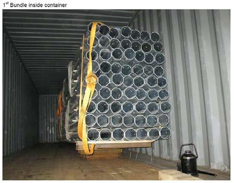
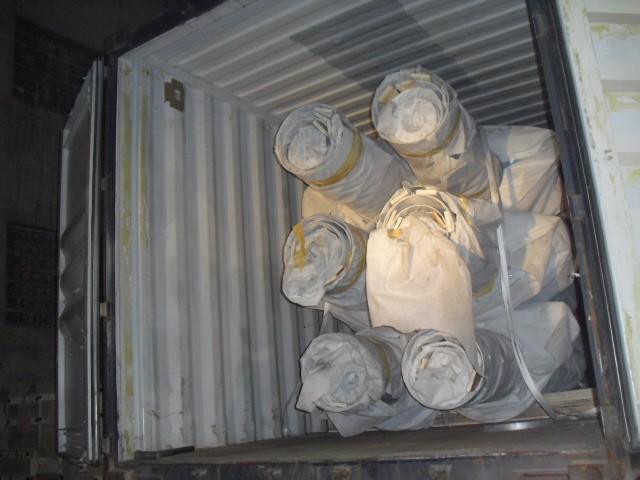
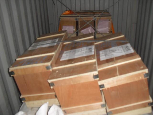
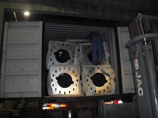
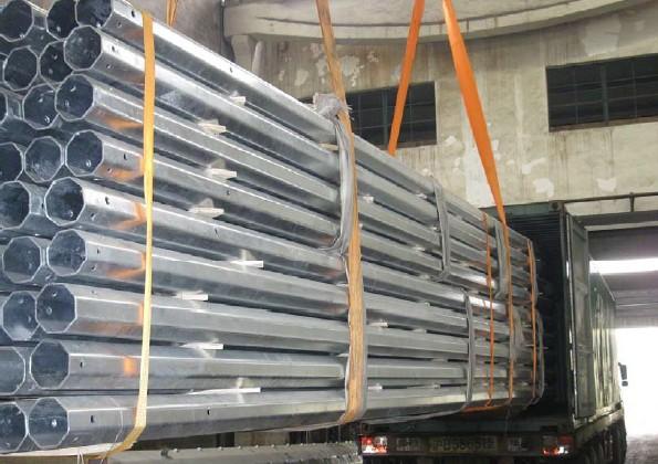
14 How dry containers are loaded Examples of loaded dry container contents

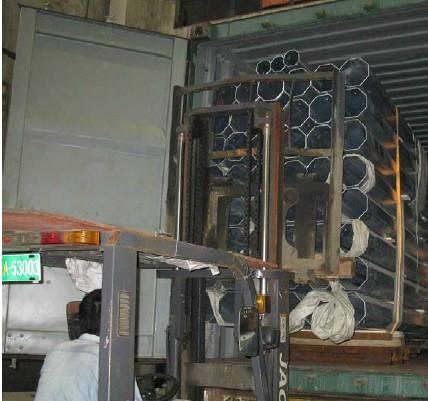
 Bind the 10T-capacity strap at the end of one bundle and tie up on the forklift frame Raise the bundle slightly with the forklift and then gently pull the bundle out.")
15 General Procedure for unloading a dry container Park the trailer on a hard, flat ground surface Open one of the container doors and inspect the appearance of each bundle of towers. If everything appears to be stable, then open the other container door. Have one person get to upper bundles and release by removing the fixing cables. Check for a set of rollers under one end of the towers. (Towers can be unloaded with or without rollers present.) Bind the 10T-capacity strap at the end of one bundle and tie up on the forklift frame Raise the bundle slightly with the forklift and then gently pull the bundle out. If there are rollers under the towers, pull the bundle until the roller moves close to the door limit Have the second forklift drive to the side of the bundle and raise the bundle slightly at the balance point. The first forklift should move away after the bundle is raised up by the second forklift. The second forklift should truck away the bundle. Repeat the same process for another bundle until the container unloading is finished.


16 Unloading Large Towers from an Open-Top (OT) Container The tower pictured above is 120 long and was shipped in sections that are nested together, one inside the other. Towers are not always nested; sometimes they are packaged in bundles or strapped flat to a pallet. The top and rear doors on the container are shown open. Each tower section is wrapped around the outside to prevent scratches and damage. Page 1 of 4

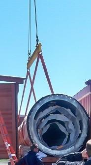
17 Attach straps to evenly distribute tower weight. Page 2 of 4


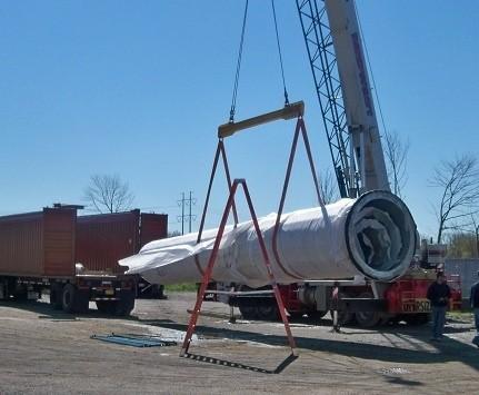
18 Lift the tower forward out of the container toward a protected solid flat surface where it can be set down. Page 3 of 4


19 Set the tower on stacked lumber or other material to keep it off the ground. If the tower is set directly on the ground, rocks and other material can puncture the protective wrapping and scratch the surface. This is especially important for powder coated towers. Page 4 of 4
Installation Instructions
 116-3027, 116-3017 X-Pando Adjustable Steel Protector Installation Instructions 1404 N. Marshall Ave. El Cajon CA. 92020 For technical support call us at (800) 368-3075 NB 6/28/10 607-0112 Step 1. Mounting
Boat Boat Loader Fitting Instructions
 Aerodynamic & Heavy Duty Roof Rack Systems Australian Made - Australian Owned www.rhinorack.com Boat Boat Loader Fitting Instructions CONTROLLED Balance point 3 Front eye nuts position 3 Transom eye nut
TOWER INSPECTION REPORT
 3010 S. Hwy 77, Suite 600 Waxahachie, Texas 75165 http://ctctower.com Office: 972/923-9504 Fax: 972/923-9619 TOWER INSPECTION REPORT PREPARED FOR MR. CUSTOMER 1,563 GUYED TOWER NEAR CITY, STATE JANUARY
PULLTARP INSTALLATION & OPERATORS MANUAL
 PULLTARP INSTALLATION & OPERATORS MANUAL Step 1. Mounting Positions Determine the mounting position for your truck Fig. 1 - Fig. 7. Fig. 1 Fig. 2 Fig. 3 A Mount Top Or Bottom Roll B Mount Top Or Bottom
Assembly Guide ST200 FUNCTIONAL TRAINER
 Assembly Guide ST200 FUNCTIONAL TRAINER Assembly Guide ST200 FUNCTIONAL TRAINER To avoid possible damage to this Functional Trainer, please follow these assembly steps in the correct order. Before proceeding,
Tripod Setup Guide (M-TPx)
") Items needed: 1/2 inch wrench, mast level (M-MLA), medium size wire cutters, crescent wrench, all-purpose grease, tape measure, tie wraps, redi-mix cement (optional), shovel (optional), sledge hammer (for
Items needed: 1/2 inch wrench, mast level (M-MLA), medium size wire cutters, crescent wrench, all-purpose grease, tape measure, tie wraps, redi-mix cement (optional), shovel (optional), sledge hammer (for
STATIONARY TRUCK INTERNAL HALYARD CAM CLEAT FLAGPOLES FOR QUICK AND PROFESSIONAL COMMERCIAL INSTALLATION READ ALL INSTRUCTIONS BEFORE PROCEEDING
 9390 South 300 West, Sandy, Utah 84070 801-562-0123 800-782-0500 ColonialFlag.com STATIONARY TRUCK INTERNAL HALYARD CAM CLEAT FLAGPOLES FOR QUICK AND PROFESSIONAL COMMERCIAL INSTALLATION READ ALL INSTRUCTIONS
Thank you for purchasing a WIKE BOX BIKE!
 Thank you for purchasing a WIKE BOX BIKE! Contents Safety.....3 Front wheel.4 Kickstand..5 Handle Bar & Box 6 Seat post and Saddle 7 Final pre-ride check 8 Tools needed to assemble Bike: -High table or
REPLACING THE AFT RUDDER CABLES
 REPLACING THE AFT RUDDER CABLES Note: You must have the assistance of a qualified Aircraft Mechanic to perform this procedure. A logbook entry with the mechanics signature is required. Please read these
BRONZE BUSHING REPLACEMENT PROCEDURE DN345 & NL450C
 1 BRONZE BUSHING REPLACEMENT PROCEDURE V.2 12/3/2014 DN345 & NL450C 2 Safety Instructions Removing Walking Beams 3 1. Position spreader on a flat concrete surface capable of supporting weight of spreader
1.0 - OPENING AND CLOSING THE DOOR
 The purpose of this manual is to provide the user with instructions on how to safely open and close, how to conduct routine maintenance, and how to install the PEI TWINLOCK Closure on a pressure vessel.
HoldUp Plus2. Safety Kit included: See additional instructions for installation. REAR WHEEL TRAY. BASE (1x) lock WASHER (1x) KEY (2x) SAFETY CLIP (1x)
 lock WASHER (1x) KEY (2x) SAFETY CLIP (1x)") HoldUp Plus2 InsTAll This product on 2" hitch version of the HoldUp Front WHEEL TRAY assembly (1x) REAR WHEEL TRAY assembly (1x) wrench (1x) BASE (1x) bolt (8X) Lock WASHER (8X) Washer (8x) KEY (2x) SAFETY
HoldUp Plus2 InsTAll This product on 2" hitch version of the HoldUp Front WHEEL TRAY assembly (1x) REAR WHEEL TRAY assembly (1x) wrench (1x) BASE (1x) bolt (8X) Lock WASHER (8X) Washer (8x) KEY (2x) SAFETY
STATIONARY TRUCK INTERNAL HALYARD V-CLEAT FLAGPOLES FOR QUICK AND PROFESSIONAL INSTALLATION READ ALL INSTRUCTIONS BEFORE PROCEEDING
 9390 South 300 West, Sandy, Utah 84070 801-562-0123 800-782-0500 ColonialFlag.com STATIONARY TRUCK INTERNAL HALYARD V-CLEAT FLAGPOLES FOR QUICK AND PROFESSIONAL INSTALLATION READ ALL INSTRUCTIONS BEFORE
Instructions. Follow All Instructions Before Assembling Or Using This Product
 Instructions Follow All Instructions Before Assembling Or Using This Product IMPORTANT DO NOT RETURN THIS PRODUCT TO THE RETAIL STORE WHERE PURCHASED. CALL TOLL FREE: (800) 492-9334 WARNING: Improper use
American Flagpole & Flag Co. 1(800)
") SENTRY CONCEALED HALYARD-REVOLVING TRUCK GROUND SET INSTALLATIONS INSTRUCTIONS 1. Dig foundation as detailed in SECTION A FOUNDATION SPECIFICATIONS, set sleeve in enter of hole with top 2 above grade.
SENTRY CONCEALED HALYARD-REVOLVING TRUCK GROUND SET INSTALLATIONS INSTRUCTIONS 1. Dig foundation as detailed in SECTION A FOUNDATION SPECIFICATIONS, set sleeve in enter of hole with top 2 above grade.
Installation and Training Manual
 AirForce1 Tower Kit Installation and Training Manual FuturEnergy Limited Ettington Park Business Centre Stratford upon Avon CV37 8BT +44 (0)1789 451070 Table of Contents Safety Notes... 3 Parts Supplied
LITERIDER 2&3 IMPORTANT WARNING. 2Bike (1x) Bolt (1x) Nut (1x) Small Hex Wrench (1x)
 Bolt (1x) Nut (1x) Small Hex Wrench (1x)") LITERIDER 2&3 3 Bike (1x) Bolt (1x) Flat Washer (2x) Nut (1x) Large Hex Wrench (1x) 2Bike (1x) wrench (1x) Small Hex Wrench (1x) keys (2x) Long Strap (1x) 2-Zip Strips (6x) 3-Zip Strips (9x) Wheel strap
LITERIDER 2&3 3 Bike (1x) Bolt (1x) Flat Washer (2x) Nut (1x) Large Hex Wrench (1x) 2Bike (1x) wrench (1x) Small Hex Wrench (1x) keys (2x) Long Strap (1x) 2-Zip Strips (6x) 3-Zip Strips (9x) Wheel strap
Chapter 2 Rigging. Cutting Wire Rope. Anchoring Wire Rope to Drum. Winding Wire Rope Onto Drum
 Chapter 2 Rigging Cutting Wire Rope The wire rope must be tightly seized on both sides of the point where the wire rope will be cut, as shown in Figure 2-1. Seize the wire rope with either seizing wire
KTM OM-2 SPLIT BODY FLOATING BALL VALVES INSTALLATION AND MAINTENANCE INSTRUCTIONS
 Before installation these instructions must be fully read and understood SECTION 1 - STORAGE 1.1 Preparation and preservation for storage All valves should be properly packed in order to protect the parts
Side-of-Pole Mount for 1 Module (SPM1) For Module Types A & B
 For Module Types A & B") Side-of-Pole Mount for 1 Module (SPM1) For Module Types A & B ASSEMBLY INSTRUCTIONS step-by-step assembly and installation Version 1, Rev A PCN 080311-2 SP3363-1 Side-of-Pole Mount for 1 Module (SPM1)
Side-of-Pole Mount for 1 Module (SPM1) For Module Types A & B ASSEMBLY INSTRUCTIONS step-by-step assembly and installation Version 1, Rev A PCN 080311-2 SP3363-1 Side-of-Pole Mount for 1 Module (SPM1)
Installation, Operating, Inspection and Maintenance Instructions Ladder Climber s Safety System. Warning
 OWNER'S MANUAL Installation, Operating, Inspection and Maintenance Instructions Ladder Climber s Safety System Model # s: 6000, 6001, 6010 Warning You must read and fully understand all instructions, or
MAGNETIC INDOOR CYCLING BIKE
 MAGNETIC INDOOR CYCLING BIKE SF-B1805 USER MANUAL IMPORTANT! Please retain owner s manual for maintenance and adjustment instructions. Your satisfaction is very important to us, PLEASE DO NOT RETURN UNTIL
Instructions. Follow All Instructions Before Assembling Or Using This Product
 Instructions Follow All Instructions Before Assembling Or Using This Product IMPORTANT DO NOT RETURN THIS PRODUCT TO THE RETAIL STORE WHERE PURCHASED. CALL TOLL FREE: (800) 492-9334 WARNING: Improper use
INSTALLATION COMMISSIONING, OPERATION & MAINTENANCE MANUAL
 WedgeRock RW Series Worm Gear Actuators INSTALLATION COMMISSIONING, OPERATION & MAINTENANCE MANUAL Revision 01 Date 4/3/17 Page 1 Table of Contents 1.0 INTRODUCTION... 4 1.1 PURPOSE... 4 1.2 AUDIENCE...
L.Ph. Bolander & Sons 1355 Evans Ave. 800/
 L.Ph. Bolander & Sons 1355 Evans Ave. 800/434-5611 San Francisco, Ca. 94124 Fax 415/648-0402 GOUNDSET ALUMINUM FLAGPOLE INSTALLATION INSTRUCTIONS STEP 1: DIG THE HOLE TO THE DIMENSIONS LISTED BELOW STEP
Parts: Included in the parts box: Inner Rear Tire Tray. Inner Front Tire Tray. Trail Doc Clamp. Pivot Assembly. Trail Doc Post.
 NV 2.0 2 Parts: Outer Front Tire Tray Inner Front Tire Tray Outer Rear Tire Tray Inner Rear Tire Tray Pivot Assembly Trail Doc Clamp Trail Doc Post Included in the parts box: 6mm Allen Wrench M6 Lock Washer
Wellhead Mast. Installation and Operation Guide. Nanometrics Inc. Kanata, Ontario Canada
 Installation and Operation Guide Nanometrics Inc. Kanata, Ontario Canada 2001 2005 Nanometrics Inc. All Rights Reserved. Installation and Operation Guide The information in this document has been carefully
BALL STOP INSTALLTION GUIDE
 BALL STOP INSTALLTION GUIDE GROUND SLEEVE INSTALLATION: 1. Locate the exact location of the ground sleeve. NOTE: Maximum recommended pole spacing is 20 feet on center. 2. Excavate the pole footing; refer
310 SERIES TILT-TO-LOAD ROTATOR. The Specialist In Drum Handling Equipment
 OPERATOR S MANUAL FOR MORSE TILT-TO-LOAD DRUM ROTATOR SAFETY INFORMATION: While Morse Manufacturing Co. drum handling equipment is engineered for safety and efficiency, a high degree of responsibility
MANUAL OF HANDLING, TRANSPORTATION AND STORAGE OF ELECTRICAL CABLE REELS
 MANUAL OF HANDLING, TRANSPORTATION AND STORAGE OF ELECTRICAL CABLE REELS OBJECTIVE Establish conditions for the proper handling, transportation and storage of electric cable reels, in order to keep the
8MAY15 US RACK, Inc Falcon Drive, Madera, CA
 8MAY15 US RACK, Inc. - 2850 Falcon Drive, Madera, CA 93637-559-661-3050 INSTRUCTIONS for Bedrail-mounted MOTORCYCLE RACK, Model 2001-4TRA WARNING: Do NOT attempt to install or use this rack without following
RATCHET RELEASE SHACKLE
 RATCHET RELEASE SHACKLE INNOVATIVE PILING EQUIPMENT HYDRAULIC PILING HAMMERS EURO RATCHET RELEASE SHACKLE FOR STEEL ERECTION OPERATORS INSTRUCTIONS & SPARE PARTS LIST EXCAVATOR MOUNTED VIBRATORS EXCAVATOR
MODEL SWH10 1,000 LB CAPACITY SWIVEL HOIST
 MODEL SWH10 1,000 LB CAPACITY SWIVEL HOIST PARTS BREAKDOWN AND OPERATING MANUAL Copyright 2007, Arcan Professional Tools Rev: 05/15/07 This operating manual contains important safety information. Read
80 SERIES MOBILE-KARRIERS. The Specialist In Drum Handling Equipment OPERATOR S MANUAL FOR MORSE 80 SERIES
 OPERATOR S MANUAL FOR MORSE Model 80A and 80A-M for 55 gallon standard steel drums (22½ diameter) Model 80C for steel or fiber drums (21-23 diameter) Model 80i for 55 gallon steel drum (22-½ diameter).
BEAMGUARD SAFETY POST TM INSTRUCTIONS
 BEAMGUARD SAFETY POST TM INSTRUCTIONS READ THESE WARNINGS BEFORE USING THE BEAMGUARD SAFETY POST! 1. Before use of this system, read and understand all instructions, warnings, cautions and notes marked
Troyer s Gourd Rack 8 unit F R H O P
 B E A D I M-N L Vertical Parts F R H O P Horizontal Parts C G J Updated 11/16 Parts List A: Top of Pole B: Bottom of Pole C: 48 Ground Stake D: Top Perch rods 48 long E: Hub F: Rope Winder w/ attached
Stand-N-Fish FULL DETAIL INSTALLATION INSTRUCTIONS
 1 Stand-N-Fish FULL DETAIL INSTALLATION INSTRUCTIONS Thank you for purchasing the incredible new Stand-N-Fish Kayak Fishing System. Once installed on your kayak the Stand-N-Fish will take your kayak fishing
600 / 600FC OWNER'S MANUAL
 PROGRESSION 600 / 600FC OWNER'S MANUAL Issue 2 / Version E - Dec. 10, 1997 Copyright 1997 GAMMA Sports - All Rights Reserved PROGRESSION 600 / 600FC OWNER'S MANUAL TABLE OF CONTENTS PAGE 1... WARRANTY
SALCO PRODUCTS, INC. PRESSURE RELIEF VALVE STORAGE, INSTALLATION, OPERATING, MAINTENANCE/TESTING, AND INSPECTION INSTRUCTIONS
 STORAGE INSTRUCTIONS Until it is time to install a new or reconditioned valve on the car, the valve must be kept in its original packaging in order to protect it from dirt and damage. INSTALLATION INSTRUCTIONS
MSA Latchways Ladder System
 Systems overview 1 of 13 Important information Individuals or organisations carrying out the installation of a MSA Latchways ladder fall protection system shall read, understand and follow these instructions
Operating instructions. Bolt-on Bar Joist Anchorage
 Reliance Industries, LLC Operating instructions for the Bolt-on Bar Joist Anchorage Model # 3072 Reliance Industries, LLC PO Box 140008 Denver, CO 80214 Ph. (800) 488-5751 Ph. (303) 424-8650 Fax (303)
7130 Lancer Rear Drive Magnetic Commercial Indoor Cycling Bike
 7130 Lancer Rear Drive Magnetic Commercial Indoor Cycling Bike Owner s Manual Made in Taiwan INDEX IMPORTANT SAFETY INFORMATION... 1 EXPLODED DRAWING... 2 PARTS LIST... 3 ASSEMBLY INSTRUCTION... 4-9 USER
by Master Halco ANCHOR GATE SYSTEMS Swing Gates Overhead Slide Gates Cantilever Slide Gates Vertical Lift Gates Fencing Without Boundaries.
 by Master Halco ANCHOR GATE SYSTEMS Swing Gates Overhead Slide Gates Cantilever Slide Gates Vertical Lift Gates Fencing Without Boundaries. The Better Way To Build Your Cantilever Slide Gates... The Principle
Charmborough Bells Risk Assessment and Method Statement
 Charmborough Bells Risk Assessment & Method Statement Charmborough Bells Risk Assessment and Method Statement Introduction This risk assessment and method statement has been prepared to outline the procedures
PRO1030 Bi-Directional Assembly Replacement
 PRO1030 Bi-Directional Assembly Replacement 1. Remove both side covers using the Crank and Cover Removal procedure. Fig. 1 2. Disconnect both brake cables (not shown) from the brake (S3611). (Fig. 1) 3.
Gurney Flap for WRX and STI w/low Profile Trunk Spoiler
 Gurney Flap for 2015+ WRX and STI w/low Profile Trunk Spoiler 2017-12-05 Thank you for purchasing this PERRIN product for your car! Installation of this product should only be performed by persons experienced
SANTANA STOWAWAY TANDEM WITH AIRLINER SAFECASE AND FTS FOAM TRAY SYSTEM ASSEMBLY AND DISASSEMBLY
 SANTANA STOWAWAY TANDEM WITH AIRLINER SAFECASE AND FTS FOAM TRAY SYSTEM ASSEMBLY AND DISASSEMBLY Congratulations! You are now the proud owner of the world s most travel-ready, performance tandem. The following
Work Standard CABLE PULLING OPERATIONS
 Page 1 of 19 ****This document supercedes BECo WMS 2.9-1.1**** 1.0 Purpose CABLE PULLING OPERATIONS 1.1 This Work Method Standard prescribes the preferred methods of removing and installing cables between
THOR 10 HAMMER CAGE INSTRUCTIONS
 75 " 7m 78 4" m 6" 8.8m 45 ".70m 4.9deg 6 4" 6m 44 4".67m 75 " 7m 9 4" 0m 44".m 497 4".64m The 70, Thor Hammer Cage, consists of four heavy duty aluminum net poles. The unique pole structure reduces the
Disassembling and assembling APP and APP 16-22
 MAKING MODERN LIVING POSSIBLE Instruction Disassembling and assembling APP 11-13 and APP 16-22 ro-solutions.com Table of Contents 1. Disassembling...3 2. Disassembling the pump...3 3. Assembling the pump....7
BELT DRIVE INDOOR CYCLING BIKE SF-B1712 USER MANUAL
 BELT DRIVE INDOOR CYCLING BIKE SF-B1712 USER MANUAL IMPORTANT! Please retain owner s manual for maintenance and adjustment instructions. Your satisfaction is very important to us, PLEASE DO NOT RETURN
APP pumps APP and APP Disassembling and assembling
 Service guide APP pumps APP 11-13 and APP 16-22 Disassembling and assembling hpp.danfoss.com Table of Contents Contents 1. Introduction... 2 2. Disassembling the pump... 3 3. Assembling the pump... 6 4.
Rocky Mountain Instinct / Pipeline Alloy Frame Assembly Guide. Date: April 7, 2017
 Rocky Mountain Instinct / Pipeline Alloy Frame Assembly Guide Date: April 7, 2017 1 Table of Contents Front Triangle Preparation... 4 Parts Needed... 4 Instructions... 4 Chain Stay Preparation... 6 Parts
I.H.S INSTALLATION INSTRUCTIONS
 I.H.S INSTALLATION INSTRUCTIONS TOOLS REQUIRED The following tools will be required for installation of your I.H.S. system. Item Qty Needed 9/16 Open End Wrench 2 3/4 Open End Wrench 1 1/2 Open End Wrench
CHAPTER 5 REWIND STARTERS
 GENERAL INFORMATION CHAPTER 5 REWIND S Rewind starters used on vertical shaft Tecumseh engines are top mount horizontal pull style or side mount vertical pull style. Horizontal shaft engines use side mounted
OPERATION and MAINTENANCE Guide
 Catalog No. AIR1000 Winch and Hoist OPERATION and MAINTENANCE Guide Cat. No. AIR1000 1250 Lb. Single Line Pull READ THIS BEFORE OPERATING UNIT INSTALLATION: Mount on clean, flat surface. Use 1/2" mounting
Xtender30. Home Batting Cage. Assembly Instructions
 Xtender30 Home Batting Cage Assembly Instructions IMPORTANT DO NOT RETURN THIS BATTING CAGE TO THE RETAIL STORE WHERE PURCHASED. CALL TOLL FREE: (800) 492-9334 IMPORTANT WARRANTY WARNING: DO NOT LEAVE
HOME ASSEMBLY INSTRUCTIONS
 HOME ASSEMBLY INSTRUCTIONS This Papillionaire Bicycle now belongs to you. It will take you to work, wait patiently outside your local cafe, and carry your groceries home. This is the start of your long-term
2,500/4,000 LB Easy Riser Vertical Cable Feighner Lift
 2,500/4,000 LB Easy Riser Vertical Cable Feighner Lift CAUTION - PUT SAFETY FIRST 1. Before attempting to install or operate this lift, study and fully understand the proper operating procedures and safety
INSTRUCTION MANUAL. January 23, 2003, Revision 0
 INSTRUCTION MANUAL Model 810A In-Vitro Test Apparatus for 310B Muscle Lever January 23, 2003, Revision 0 Copyright 2003 Aurora Scientific Inc. Aurora Scientific Inc. 360 Industrial Parkway S., Unit 4 Aurora,
OPERATIONS/PARTS MANUAL FOR PATTERSON'S WWP75H-10 HYDRAULIC WINCH.
 W. W. Patterson Company 3 Riversea Road Pittsburgh, PA 15233 Phone: 800-322-2018 FAX: 412-322-2785 OPERATIONS/PARTS MANUAL FOR PATTERSON'S WWP75H-10 HYDRAULIC WINCH. Please fill in the following blanks
CH Packaging Operations Manual
 DOE/WIPP 02-3184 Revision 0, January 2002 CH Packaging Operations Manual Processing and final preparation of this paper was performed by Westinghouse TRU Solutions, LLC, the WIPP management and operating
Proof load is the load applied in performance of a proof test. Proof test is a nondestructive tension test performed by the sling manufacturer or an
 1910.184 Slings (a) Scope. This section applies to slings used in conjunction with other material handling equipment for the movement of material by hoisting, in employments covered by this part. The types
Universal Elevator Mount Owners Manual Customer Service Center N53 W24700 South Corporate Circle Sussex, WI U.S.A.
 REQUIRED TOOLS AND MATERIALS: 2 Capable Adults Carpenter s Level 15 Tape Measure Pencil Universal Elevator Mount Owners Manual Customer Service Center N53 W2400 South Corporate Circle Sussex, WI 530 U.S.A.
Drive Belt Instructions
 Drive Belt Safety Do not roll, pry, twist, invert or bend the belt back on itself. Do not zip tie the belt. The acceptable temperature range for your belt drive is -53 C to 85 C. Do not lubricate the belt
INSTALLATION INSTRUCTIONS PUSH BAR PULLMAN PANIC BOLT DEVICE TO EN 1125 : 2008
 INSTALLATION INSTRUCTIONS PUSH BAR PULLMAN PANIC BOLT DEVICE TO EN 1125 : 2008 0376/448/00 ISSUE 01 EMERGENCY PUSH PAD PULLMAN BOLT DEVICE TO EN 179 : 2008 1000mm MAXIMUM CLEAR OPENING HEIGHT WITH PUSH
! CAUTION! ! WARNING! General Information
 Great Plains Mfg., Inc. Installation Instructions Used with: 2SF24, 24-Foot Two-Section Drill General Information Two-Section, Hydraulic Folding Marker 2SF30, 30-Foot Two-Section Drill 2SBM30, 30-Foot
CLIMBING STEEL POLES INSTRUCTOR GENERAL LESSON OUTLINE ONLINE/CLASSROOM SESSION
 INSTRUCTOR GENERAL LESSON OUTLINE ONLINE/CLASSROOM SESSION This lesson describes different steel pole steps and discusses strategies for climbing, descending, and positioning steel poles to reach work
S-60-TO : 1 ton tower system INSTRUCTION MANUAL
 S-60-TO : 1 ton tower system INSTRUCTION MANUAL LIVE SYSTEMS bvba Mandellaan 282 8800 B-Roeselare Tel: +32(0)51 69 38 14 Mobile : +32 (0) 495 24 24 67 e-mail: ricky@livesystems.be BTW : 0859.636.665 1
Side-of-Pole Mount for 1 Module (SPM1) For Module Type C
 For Module Type C") Module Type Width Length C 22-27 56-63 Side-of-Pole Mount for 1 Module (SPM1) For Module Type C ASSEMBLY INSTRUCTIONS step-by-step assembly and installation Version 1, Rev A PCN 022212-1 Side-of-Pole Mount
Module Type Width Length C 22-27 56-63 Side-of-Pole Mount for 1 Module (SPM1) For Module Type C ASSEMBLY INSTRUCTIONS step-by-step assembly and installation Version 1, Rev A PCN 022212-1 Side-of-Pole Mount
QUALITY ALUMINUM BOAT LIFTS, INC. INSTRUCTIONS. Dominator Lake Lift
 INSTRUCTIONS Dominator Lake Lift PHONE:251-986-3882 * FAX:251-986-3136 QABLDOMINATORINST.2014 P a g e 1 Quality Aluminum Boat Lifts, INC. Installation Instructions: Dominator Lake Lift Thank you for your
SECURITY AND CONFIDENCE AT HEIGHT
 Detachable Cable Sleeve SECURITY AND CONFIDENCE AT HEIGHT THE ULTIMATE IN FALL PROTECTION THE DANGERS OF WORKING AT HEIGHT Every day, workers around the world climb ladders to great heights to get their
INSTALLATION, OPERATION AND MAINTENANCE GUIDE
 INSTALLATION, OPERATION AND Placement in Pipeline System When installing Process Development & Control s ElastoTITE Elastomer-Hinged Check Valves in a pipeline, a minimum of five pipe diameters should
CRUZBIKE Quest 2.0 Assembly
 CRUZBIKE Quest 2.0 Assembly CRUZBIKE Quest 2.0 Assembly... 1 General notes on assembly... 2 Un box and evaluate the frame and major parts... 2 Unfold the rear swing arm and arrange the frame... 3 Rear
602 STRINGING MACHINE OWNER'S MANUAL
 PROGRESSION 602 STRINGING MACHINE OWNER'S MANUAL AL Issue 1- April 2000 Copyright 2000 GAMMA Sports - All Rights Reserved PROGRESSION 602 STRINGING MACHINE TABLE OF CONTENTS PAGE 1... WARRANTY PAGE 2...
STAND AID 1600/ ECONOSTAND
 MAKERS OF STAND AID, POWER TOILET AID AND FREEDOM CHAIR STAND AID 600/ ECONOSTAND INSTRUCTIONS AND WARRANTY FOR STAND AID 600 STAND AID SERIAL # PO BOX 386 Sheldon, IA 50 (800) 83-8580 (7) 34-53 Fax: (7)
Shoreline Cantilever Lift 2500lb Capacity Models: (108" inside width) - Part # (120" inside width) - Part #
 - Part # (120 inside width) - Part #") Shoreline Cantilever Lift 2500lb Capacity Models: 25108 (108" inside width) - Part # 1017402 25120 (120" inside width) - Part # 1017403 1. 2. 3. 4. 5. CAUTION - PUT SAFETY FIRST Before attempting to install
Shoreline Cantilever Lift 2500lb Capacity Models: 25108 (108" inside width) - Part # 1017402 25120 (120" inside width) - Part # 1017403 1. 2. 3. 4. 5. CAUTION - PUT SAFETY FIRST Before attempting to install
Lectric Cycles Mid-Drive Electric Motor Installation
 Lectric Cycles Mid-Drive Electric Motor Installation This write-up describes the installation of a Lectric Cycles electric motor. The model is the e-rad Mid-Drive 750 Watt conversion kit, installed on
BEAMGUARD SAFETY POST TM
 BEAMGUARD SAFETY POST TM INSTRUCTIONS-SAFETY FIRST! READ THESE WARNINGS BEFORE USING THE BEAMGUARDS! 1. Before use of this system, read and understand all instructions, warnings, cautions and notes marked
BUTTERFLY VALVES Series 800
 BUTTERFLY VALVES Series 800 WARNING Before proceeding read ALL instructions and become familiar with the equipment and associated drawings. Follow ALL applicable safety regulations and codes for pressurized
WINCH USER GUIDE WARN 3700 Utility Winch Part Number: 93700
 WINCH USER GUIDE WARN 3700 Utility Winch Part Number: 93700 Your safety, and the safety of others, is very important. To help you make informed decisions about safety, we have provided installation and
MAINTENANCE PROCEDURE FOR X 650
 MAINTENANCE PROCEDURE FOR X 650 X 650 25. juli 2005-1/6 MAINTENANCE PROCEDURE FOR X 650 2 ND STAGE WARNING: This maintenance procedure is only for appointed Scubapro technicians that completed a course
KERSPLASH POOL CLIMBING WALL INSTALLATION INSTRUCTIONS
 TOLL FREE: 1-800-476-7366 VOICE 651-665-9131 FAX 651-665-9130 EMAIL: INFO@POOLCLIMBINGWALLS.COM EVERLAST CLIMBING 1335 MENDOTA HEIGHTS ROAD MENDOTA HEIGHTS, MN 55120 2012 EVERACTIVE BRANDS Congratulations!
Columbia Taping Tools. Hydra Reach Handle. Manual
 Columbia Taping Tools Hydra Reach Handle Manual Table of contents Warning 2 Introduction 3 Before you start, identify your handle 4 What is your problem? 5 Reservoir Upgrade 5 Setting up the loading system
FRONT DERAILLEUR - CURRENT RANGE
 FRONT DERAILLEUR - CURRENT RANGE (since 2015) (since 2018) (since 2017) (since 2018) WARNING! This technical manual is intended for use by professional mechanics. Anyone who is not a qualified professional
ROTATING DISK VALVES INSTALLATION AND MAINTENANCE 1. SCOPE 3 2. INFORMATION ON USAGE 3 3. VALVE TYPES 3 4. OPERATORS 5 5. VALVE CONSTRUCTION 6
 Sub Section INDEX Page Number 1. SCOPE 3 2. INFORMATION ON USAGE 3 3. VALVE TYPES 3 4. OPERATORS 5 5. VALVE CONSTRUCTION 6 6. INSTALLATION AND OPERATION 6 7. MAINTENANCE 8 8. REPAIR 9 9. ASSEMBLY 10 10.
Reliance Industries, LLC. Installation, Operation, Inspection and Maintenance Instructions for the Skyline Horizontal Lifeline System
 Reliance Industries, LLC Installation, Operation, Inspection and Maintenance Instructions for the Skyline Horizontal Lifeline System 6300 Permanent Lifeline System using 3/8 7x19 Steel Wire Rope with the
KENNEDY VALVE OPERATION & MAINTENANCE MANUAL
 2 54 ROTATING DISC GATE VALVE OPERATION & MAINTENANCE MANUAL Rel. 5/27/16 1 TABLE OF CONTENTS 3 General 3 Receipt & Inspection 4 Gate Valve Storage & Handling 5 6 Installation 7 Operation 8 Field Testing
Rudder Kit Assembly Instructions for Quest 13
 Rudder Kit Assembly Instructions for Quest 13 Revised 4/2/2015 78501 Rudder System The Hobie Quest is designed for the addition of an optional rudder system. Rudder systems in boats like this allow you
Threaded Closures Installation, Operation & Maintenance
 Howard Street Bulletin TT Louisville, KY 0 USA Revised Jan 0 Phone 0--0 Fax 0--00 Threaded Closures Installation, Operation & Maintenance Caution: Operating a closure can be a hazardous activity and certain
INDOOR CYCLING BIKE SF-B1110 USER MANUAL
 INDOOR CYCLING BIKE SF-B1110 USER MANUAL IMPORTANT! Read all instructions carefully before using this product. Retain owner s manual for future reference. For customer service, please contact: support@sunnyhealthfitness.com
VERSA BIKE RACK INSTRUCTIONS
 VERSA BIKE RACK INSTRUCTIONS Models #8, 8 Important This rack is designed for use with a or. receiver hitch. The rack is designed to hold a maximum of two bicycles. Do not use it for anything other than
USE, ASSEMBLING AND MAINTEINANCE INSTRUCTIONS FOR CLIMBING LADDER
 www.palicampion.it use, assembling and maintenance istrucrions for climbing ladder. rev130616 Pag. 1 di 9 USE, ASSEMBLING AND MAINTEINANCE INSTRUCTIONS FOR CLIMBING LADDER IMPORTANT: This documents concerns
Paddle Bar Replacement
 This procedure is to help facilitate the replacement of the 23 Paddle Bar Assembly on the ANKOM Dietary Fiber Analyzer. Note: The following items will be sent in a replacement package as part of the 23
Deluxe Gourd Racks I D E G A. Parts List. Shown above are parts for the two-level, Deluxe Gourd Rack (DGR 12V)with 12 arms for vertically hung gourds.
with 12 arms for vertically hung gourds.") Deluxe Gourd Racks H F K I D E J C G A Shown above are parts for the two-level, Deluxe Gourd Rack (DGR V)with arms for vertically hung gourds. Parts List Code Quantity A B C D E F G H I J 6, or 4 6, or
Deluxe Gourd Racks H F K I D E J C G A Shown above are parts for the two-level, Deluxe Gourd Rack (DGR V)with arms for vertically hung gourds. Parts List Code Quantity A B C D E F G H I J 6, or 4 6, or
CAISSON SHAFT SYSTEM
 CAISSON SHAFT SYSTEM Installation Guide INSTALLATION GUIDE FOR DN2000 TO DN3660 UNITS PLATE JOINTING SYSTEM This guide is to be used for the Installation of CPM Group Ltd caisson shaft units which use
Ropework. Stopper knots. Overhand Knot ROPEWORK. Figure of Eight 3.
 Ropework 1 Ropework Stopper knots Stopper knots are used as a temporary method of stopping a rope from fraying or as a method of locking other knots which maybe prone to lossening. The knots are the Overhand
GV Standard X-Vent. Setup, Commissioning & Installation Guide
 GV Standard X-Vent Setup, Commissioning & Installation Guide Technical experts in the design, manufacture and supply of precision engineered, architectural rooflights for residential and commercial buildings.
ST Shimano Total Integration. Technical Service Instructions. General Safety Information SI-6CT0B
 Technical Service Instructions SI-6CT0B t ST-4400 Shimano Total Integration Shimano Total Integration Features The Shimano Total Integration TIAGRA series features a dual action control lever which actuates
Heavy Equipment & Rigging Specialist Training
 Heavy Equipment & Rigging Specialist Training Module 1 Unit 4: Intro to Rigging May08 1 Key Points Review of Exercise Goals Discuss Rigging Components Language of Crane Signals Review Anchor Installation