New edition 2017 / 08. Technical Brochure. verope special wire ropes
|
|
|
- Sara French
- 6 years ago
- Views:
Transcription


1 New edition 2017 / 08 Technical Brochure verope special wire ropes
2 Contents 1. Rope Technology Basics 1.1 All about wire Raw material Manufacturing process Wire surfaces Wire forms Wire tensile strength 1.2 All about the strand Lay length of a strand Lay direction of a strand Diameter of a strand Strand design Compacted round strands Fill factor of a strand 1.3 All about the rope Wire rope diameter Measuring Devices and their correct handling Types of measuring devices Lay direction of a wire rope Rope design Fill factor of a rope Lay types of wire ropes Low-tension wire ropes Types of rope cores (abbreviated designations according to EN ) Semi rotation-resistant wire ropes Rotation-resistant wire ropes Wire rope lubricant & Re-lubrication 2. Rope Characteristics 2.1 Breaking strength 2.2 Bending fatigue resistance 2.3 Flexibility 2.4 Efficiency factor 2.5 Wear resistance 2.6 Deformation Behavior Modulus of elasticity Radial stability Structural stability Diameter reduction of a special wire rope 3. Why special wire ropes? 3.1 Plastic Layer 3.2 Breaking Strengths Breaking strengths and Swivel 3.3 Bending fatigue and rope lifetime Bending fatigue when using steel or plastic sheaves Bending fatigue of ungalvanized and galvanized ropes Bending fatigue in dependence on the groove diameter Bending fatigue in dependence on the line pull Bending fatigue in dependence of the sheave diameter Page 4 Page 4 Page 4 Page 4 Page 4 Page 4 Page 4 Page 5 Page 5 Page 5 Page 6 Page 6 Page 8 Page 8 Page 10 Page 10 Page 10 Page 11 Page 12 Page 12 Page 12 Page 13 Page 14 Page 14 Page 14 Page 14 Page 16 Page 17 Page 17 Page 17 Page 17 Page 18 Page 18 Page 20 Page 20 Page 22 Page 22 Page 22 Page 23 Page 23 Page 24 Page 25 Page 25 Page 30 Page 30 Page 31 Page 32 Page 32 2
3 3.4 Deformation behavior Modulus of elasticity Elongation Diameter reduction Radial stability with and without load 3.5 Rotational Behavior 3.6 Flexibility 3.7 Efficiency Factor 4. Discard Criteria (ISO 4309) 5. Crane components 5.1 Drums 5.2 Sheaves 6. Choose the right rope for your application 6.1 Application view 6.2 Rope view Hoist Application Usage of a swivel on hoist ropes More crane applications 6.3 Application of ordinary (or regular) lay and lang s lay ropes Ordinary lay ropes Lang s lay ropes 7. Rope requirements from the crane view 8. Rope End-fittings 8.1 Points of reference to determine the rope length precisely 8.2 Efficiency factor K T of rope end-fittings 9. General Information 9.1 Handling and Storage of ropes Handling of reels Rope Storage 9.2 Installation of wire ropes Control of the new rope Inspection of sheave grooves Rope Installation Process Initial operation after installation process Rope installation with multi-layer spooling Importance of preliminary tension of ropes with multi-layer spooling 10. Safety Instructions 11. Use of metrical ropes on imperial cranes and of imperial ropes on metrical cranes 12. verope Service and R&D Center 13. Worldwide service and distribution Page 33 Page 34 Page 35 Page 36 Page 37 Page 39 Page 40 Page 40 Page 42 Page 44 Page 44 Page 44 Page 46 Page 46 Page 46 Page 46 Page 48 Page 50 Page 52 Page 52 Page 52 Page 54 Page 56 Page 56 Page 56 Page 58 Page 58 Page 58 Page 58 Page 59 Page 59 Page 60 Page 61 Page 62 Page 62 Page 63 Page 64 Page 66 Page 68 Page 70 3
4 1. Rope Technology Basics 1.1 All about wire Raw material Wires are usually made from specified carbon steel. The carbon content is between 0,4% and 1%, the manganese content between 0,3% and 1%, the silicon content between 0,1% and 0,3% and the contents of phosphorus and sulphur each under 0,45%. Wire forms A distinction is made between the wire shapes. A round wire is a wire with a round cross section. Every wire that has a non-round cross section is called a profiled wire. There are oval wires, flat wires, Z- and S-profiled wires, H-shaped wires, trapezoidal or wedge shaped wires and triangular wires. Profiled wires are produced by drawing or rolling processes. Manufacturing process Wire rod of 6 to 9mm diameter, the raw material, will be transformed to the desired strength, diameter or shape by rolling or drawing in a cold forming process. Wire surfaces Galvanized wires are zinc coated by going through a bath of liquid zinc. The wire is called finally galvanized if it does not get drawn further after this process. If the wire cross section is further reduced after this process, the wire is called drawn galvanized. Bright wires, uncoated, are indicated with the capital letter U, whereas zinc coated wires are divided into class A and class B, depending on the a zinc weigth coating Tensile strength N/mm 2 Wire tensile strength The tensile strength of a wire is defined as the maximum tensile force a wire can stand in longitudinal direction without breaking, divided by the cross section of the wire. The nominal tensile strength of a wire is a theoretical value, the actual tensile strength of the wire should not fall below the nominal tensile strength and should only exceed it in defined limits. Rope wires with the nominal tensile strengths of 1770 N/mm2, 1960 N/mm2 and 2160 N/mm2 are commonly used in modern wire ropes. Wire strength Wire grade 1770 N/mm N/mm N/mm2 4
.")


 the wires are rotated counterclockwise")
5 1.2 All about the strand A strand consists of one or multiple layers of wires, which are wound in a helical shape around an insert (figure 1). 2 nd Layer (Outer Wires) 1 st Layer Insert (Core Wire) Figure 1: Components of a strand Figure 2: left hand lay Figure 3: right hand lay Lay length of a strand The lay length of a strand is generally understood as the pitch of the helical lay of the wires, which means the lengths of a strand at which the wire circulates completely one time. By varying the lay length, the contact conditions of adjacent wires, the elastic properties and the breaking strength of a strand can be changed. Lay direction of a strand A distinction is made between right hand and left hand lay strands. The lay direction is left hand, when (moving away from the beholder) the wires are rotated counterclockwise (figure 2). The lay direction of a strand is right hand, when its wires (moving away from the beholder) are rotated clockwise (figure 3). The lay direction of a strand is often given by small s for the left hand lay strand and by a small z for the right hand lay strand. 5
6 Figure 4: Diameter of a strand Diameter of a strand Diameter of a strand The diameter of a strand is the diameter of the smallest, all wires enclosing enveloped circle. The strand diameter is usually measured with a micrometer caliper and is given accurate to 1/100mm (figure 4). Strand design One understands the formation law by the design of a strand according to which the wires are relatively to each other arranged. So all strands of the design Seale have for example the construction 1 - n - n with n=3, 4, 5, 6, 7, 8, 9.. wire layers, which get stranded parallel to each other in a single operation. According to EN these are connected by a minus - sign in the designation. 6


.")

 with a same")


")


7 Figure 5: Standard strand Figure 6: Parallel lay strand 1+N Seale The name of a Seale strand design Seale 17 is therefore 1-8-8, the designation of a strand design Seale 19 is S15 S17 S19 S21 The most important strand designs are one-, two and three layer standard strands (figure 5), as well as parallel lay strands of the strand designs Seale, Filler, Warrington and Warrington-Seale (figure 6 & 7). Warrington W13 W16 W19 W22 The two and three-layer standard strands show crossovers between the wires of the different wire layers (figure 5). Here the wire layers get stranded in separate operations in the same direction (designation N) with a same stranding angle but with different lay lengths. Filler F17 Warrington-Seale F21 F25 F29 The so called parallel lay strands (Seale, Filler, Warrington, Warrington-Seale) avoid crossovers and create line contact of the wires instead. This happens due to a stranding of all wire layers at once with different stranding angles but the same lay length (figure 6 & 7). WS26 WS31 Figure 7: Strand designs WS36 WS41 7
8 Compacted round strands A compacted round strand starts as a conventional torsion free round wire strand. The strands are compacted either during stranding or in a separate operation afterwards to form a smaller diameter by rolling or drawing. The originally round wires are heavily deformed by both the compacting tool and the adjacent wires (figure 8). Fill factor of a strand The fill factor of a strand is defined as the ratio of the metallic cross section (or as simplified calculation the sum of the single wire cross sections) related to the area of the smallest circle circumscribing the strand. The fill factor specifies the amount of space which the strand takes in the rope meaning the amount of steel. The fill factors of the most common strands are between 0,70 and 0,82. This means, that the amount of steel in the strand is about 70% to 82%. The fill factors of strands can be considerably increased by compacting. Usually the fill factor of a strand increases with an increasing number of wires. A Seale 15 strand (1-7-7) for example has a fill factor of about 0,77 and a Seale 19 strand (1-9-9) has a fill factor of about 0,79. Figure 8: Uncompacted and compacted round strands 8


9 Outer strand layer Wire Rope core Plastic layer Outer strand, here compacted and rotary swaged Figure 9: Composition of a rope (veropro 8 RS) 9
10 1.3 All about the rope Wire rope diameter A distinction is made between the nominal rope diameter and the effective rope diameter. The nominal wire rope diameter is an agreed theoretical value for the diameter of the smallest circle circumscribing the outer strands. The effective rope diameter, also called actual rope diameter, is the diameter of the smallest circle enclosing all outer strands, as measured on the rope itself. The tolerance range for the effective rope diameter is specified in related national and international standards. According to EN it is between -0% and +5% (for nominal rope diameters 8mm) This means that the effective rope diameter upon delivery must neither be smaller nor bigger than 5% than the nominal rope diameter. The tolerance range is often higher for smaller ropes like 3mm to 7mm nominal diameter. Measuring devices and their correct handling In order to define the correct effective rope diameter, the correct measuring device has to be used. The measurement should strictly be done over the round ends (circumscribed circle of the rope). If one measures in the strand valleys, the result will be inacurate. For ropes with an uneven number of outer strands, it is important that the measuring surface covers several strands (figure 10). WRONG In the Oil and Gas industry, which is firmly based on US regulations, a tolerance range from -1% to 4% is applied. The effective rope diameter changes depending on the load applied. Therefore the effective rope diameter should in critical cases be measured on a rope that is loaded with 5% of the calculated breaking strength. verope produces standard tolerances of +2% to +4% and special tolerances upon request. RIGHT Figure 10: Correct determination of the rope diameter 10


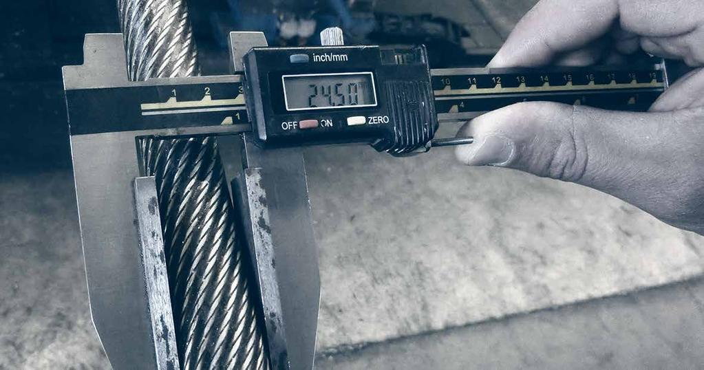
11 Types of measuring devices Figure 11: Micrometer with wide measuring surfaces Figure 12: Small caliper with wide measuring surfaces Figure 13: Big caliper with wide measuring surfaces 11
 are rotated counterclockwise (figure 14).")
12 Lay direction of a wire rope A distinction is made between right hand and left hand lay ropes. The lay direction is left hand, when the strands (moving away from the beholder) are rotated counterclockwise (figure 14). The lay direction of a rope is right hand, when its strands (moving away from the beholder) are rotated clockwise (figure 15). The lay direction of a rope is often given by a capital S for the left hand lay rope and by a capital Z for the right hand lay rope. Others often use RH for Right Hand and LH for Left Hand lay ropes. Rope design By the design of a wire rope, one understands the formation principle according to which the elements of the wire rope (the wires and the strands) are relatively arranged to each other. The designation of a fiber core is FC, for an independent steel wire rope core it is IWRC. As an example all round strand ropes of the 6x19 Warrington design with a fiber core have the construction 6 x [1-6-(6-6)] - FC. Fill factor of a rope The fill factor of a rope is defined as the ratio of the metallic cross section of the rope (or a simplified calculation of the sum of the single wire cross sections) related to the nominal rope diameter. The fill factor specifies which amount of space the wires and strands take in the rope (figure 16). The fill factors of the most common ropes are between 0,46 and 0,75. This means, that the amount of steel in the rope volume is about 46% to 75%. Wire ropes with a wire rope core have higher fill factors than ropes with a fiber core. A rope of the design 6x25 Filler-FC for example has a fill factor of 0,50 and a rope with a design 6x25 Filler-IWRC has a fill factor of 0,58. Figure 14: Left hand lay rope Figure 15: Right hand lay rope Usually fill factors of wire ropes with a fibre core (FC) decrease with an increasing number of outer strands. A rope of the design 6x25 Filler-FC has a fill factor of 0,50, a rope of the design 8x25 Filler-FC has only a fill factor of 0,
. Usually fill factors of wire ropes with a wire rope core increase with an increasing number of outer strands.")
 Figure 18: Regular lay right hand (sz) Wire ropes that are made of compacted strands have higher fill factors than ropes of uncompacted strands.")
 Figure 20: Lang s Lay right hand (zz) In regular lay ropes the lay direction of the wires in the strands is opposite to the lay direction of the strands in the")
13 Figure 16: The fill factor of the strand is the proportion of the metallic cross sections (white surfaces) at the metall cross section area of the minimum circumscribed circle (white and grey surfaces). Usually fill factors of wire ropes with a wire rope core increase with an increasing number of outer strands. A rope of the design 6x25 Filler-IWRC has a fill factor of 0,58 and a rope of the design 8x25 Filler-IWRC has a fill factor of 0,587. Figure 17: Regular lay left hand (zs) Figure 18: Regular lay right hand (sz) Wire ropes that are made of compacted strands have higher fill factors than ropes of uncompacted strands. By compacting and rotary swaging of the rope itself the fill factor can further be increased. Lay types of wire ropes Two lay types are to be considered: Regular or ordinary lay and lang s lay. Figure 19: Lang s Lay left hand (ss) Figure 20: Lang s Lay right hand (zz) In regular lay ropes the lay direction of the wires in the strands is opposite to the lay direction of the strands in the rope. We distinguish between regular lay left hand (right hand strand, left hand rope, zs) (figure 17) and regular lay right hand (left hand strand, right hand rope, sz) (figure 18). In lang s lay ropes the lay direction of the wires in the strands is equal to the strands in the rope. We distinguish between lang s lay left hand (left hand strand, left hand rope, ss) (figure 19) and lang s lay right hand (right hand strand, right hand rope, zz) (figure 20). The advantages of regular lay ropes are: Better structural stability Higher number of broken wires are allowed Easier identification of broken wires The advantages of lang s lay ropes are: Better contact in the groove of the sheaves Superior resistance to wear Longer lifetime in case of high dead loads Considerably better spooling behavior on a multi-layer drum 13
14 Low-tension wire ropes In the stranding process the initially straight wires are forced into a helical or double-helical form. Therefore the wires in a rope are always under tension even in an unloaded rope. Such a rope must be sealed very tightly left and right of the joint before cutting the rope because otherwise the free ends of the wires will spring open. By using a preforming tool the wires and strands can be deformed during the stranding strongly and plastically so they are laying nearly without tension in the rope, the rope now is preformed. The ropemakers consider such ropes to be dead. Preformed ropes can be cut much easier, also secured by seizings of course, than non-preformed ropes. Types of rope cores (abbreviated designations according to EN ) Usually wire ropes have either a fiber core (FC) or a steel/wire core. The steel/wire core can be a strand (WC) or a small rope, named as independent wire rope core (IWRC). The IWRC can be made in a separate operation or during the closing operation of the wire rope (PWRC). The wire core can also have a plastic coating (EPIWRC). Cores made of compacted strands have the additional designation (K). An independent wire core made of compacted strands is therefore called IWRC (K). A rope closed in a single operation and made out of compacted strands both in the core and the outer strands is called PWRC (K). Semi rotation-resistant wire ropes Wire ropes with a free rope end rotate to a greater or lesser extent around its longitudinal axis under the influence of tension. Wire ropes having a core lay direction opposite to the lay direction of the outer strands and 3- or 4-strand regular lay wire ropes rotate considerably less than wire ropes with the same lay direction of the wire core and the outer strands and wire ropes with fiber cores. According to VDI 2358, a wire rope is semi rotation-resistant when: the wire rope which turns around its longitudinal axis when subjected to unguided load and/or hardly transmits a torque to the attachment at the end in the event of guided rope ends. According to ISO and DIN EN : a rope is considered to be semi rotation resistant if it rotates at least once and at most four times around its axis at a length of 1000 x d under a load of 20 % of the minimum breaking force. For the twist angle, this implies: 360 < φ <1440. Rotation-resistant wire ropes According to the regulation of VDI 2358 a wire rope is rotation-resistant when: the wire rope, which hardly turns around its longitudinal axis when subjected to unguided load and/or hardly transmits a torque to the attachment at the end in the event of guided rope ends. 14
.")
15 According to ISO and DIN EN : a rope is considered to be rotation resistant if it rotates around its axis at most once at a length of 1000 x d under a load of 20 % of the minimum breaking force. The rotation can be exhibited here in rope closing or rope opening sense. For the twist angle, this implies : 360 < φ > 360 (figure 21). Figure 21: Rotation-resistant rope verotop P: the torques of the rope core and the layer of outer strands, generated under load, work in opposite directions. 15
16 Wire rope lubricant The wire rope lubricant has two major tasks: it should protect the rope from corrosion and it should minimize the friction between the rope elements themselves and between the rope and the sheave or the drum. A reduction of the friction reduces the actuating power and minimizes the wear of the rope, the sheaves and the drums. We differentiate between wax-based lubricants and oil-based lubricants. While wax-based lubricants offer a better handling of the ropes, the oil-based lubricants advantage is a better closing of the lubrication film due to the gravitational force of the oil. Re-lubrication Generally wire ropes are lubricated intensively during the production process. Nevertheless, this initial lubrication has to be renewed regularly during the whole rope s lifetime. A regular re-lubrication contributes to an increase in the rope s service life (figure 23). The lubricant used for re-lubrication needs to be compatible with the lubricant used during production. It is advised to follow the maintenance instructions in ISO The quality of the wire rope lubricant has a great impact on the fatigue resistance of a wire rope (figure 22) [%] [%] Dry rope Lubricant 1 Lubricant 2 Lubricant 3 Dry rope Basic lubrication Basic lubrication & re-lubrication Figure 22: Wire rope lubricant impact on the fatigue resistance of the wire rope Figure 23: Influence of the re-lubrication on the lifetime of a rope 16
17 2. Rope Characteristics 2.1 Breaking strength The calculated breaking strength of a steel wire rope is defined as the metallic cross section of a steel wire rope (the sum of the individual cross sections of all the wires making up the rope) multiplied by the nominal tensile strength of the steel wire rope. The minimum breaking strength of the steel wire rope is the calculated breaking strength of the rope multiplied by the spin factor. The actual breaking strength of a steel wire rope is the breaking strength of the rope as determined in a pull test. A new steel wire rope must achieve an actual breaking strength equal to or higher than the minimum breaking strength. The breaking strength of a steel wire rope can be increased by increasing the metallic area of the rope (e.g. by using strands with higher fill factors, by compacting the strands or by swaging the rope), by increasing the tensile strengths of the individual wires or by increasing the spin factor of the rope. This can also be achieved by improving the contact conditions between the rope elements by using a plastic infill. 2.2 Bending fatigue resistance The bending fatigue resistance of steel wire ropes is defined as the number of bending cycles a rope can achieve in a bending fatigue test under defined parameters (e.g. running over sheaves with a defined diameter and a predetermined line pull corresponding to the MBL of the steel wire rope). The bending fatigue resistance of the steel wire rope increases with increasing D/d ratio (= sheave diameter (D): nominal rope diameter (d)) and by reducing the line pull. The bending fatigue resistance of a steel wire rope can be increased by increasing the contact area between the steel wire rope and the sheave and by increasing the contact conditions between the rope elements, by adding a plastic layer between the IWRC and the outer strands. Due to the larger contact area between the ropes and the sheaves and due to the increased flexibility, 8- strand ropes are more resistant to bending fatigue than 6- strand ropes of a similar design. 2.3 Flexibility The flexibility of a steel wire rope typically increases with increasing a number of strands and wires in the rope. The flexibility is also influenced by the lay lengths of the strands, of the rope core and the rope as well as by the gaps between wires and strands. If a rope is not flexible enough, it will have to be forced to bend around a sheave of a given diameter, which will reduce the bending fatigue life of the rope. It will also be forced to bend around a drum of a given diameter. Spooling problems might be a consequence. 17


18 2.4 Efficiency Factor When running over a sheave a rope has to be converted from a straight condition into a bent condition at the point when the rope runs onto the sheave and has to be converted again from the bent into the straight condition when it runs off the sheave. Also the bearing has to be turned. In doing so, the friction forces in the rope as well as the friction forces in the bearing have to be overcome. This leads to a change of the rope force. One describes the relationship of the rope force on both sides of the sheave as the efficiency factor and accepts that this numerical value also takes into account the friction losses of the bearing. When measuring the efficiency factor of a rope the loss of the line pull while the rope is running over the sheave is measured. An efficiency factor of 0,98, or alternatively a strength loss of 2%, is generally assumed for wire ropes. Figure 24a: Comparison wear resistance ISO rope with conventional outer strands veropro 8 with compacted outer strands veropower 8 with compacted and rotary swaged outer strands 2.5 Wear resistance Figure 24b: contact area of strands Changes in line pull will cause changes in the rope length. Rope sections lying on a sheave or on the first wraps of a drum can only adapt to the changing line pull by sliding over the groove surface of the sheave or the drum when the length change occurs. This relative motion will cause abrasion (both in the grooves and on the special wire rope). Using less and therefore larger outer wires can increase the wear resistance of the rope. The pressure between the sheave and the rope can be minimized due to optimized contact areas; therefore also the wear of the rope can be minimized (figure 24a). The wear resistance can also be influenced by the metallurgy of the outer strands. 18


19 Wire drawing process Wire rod pickling & surface treatment 1st drawing patenting & galvanizing 2nd drawing Inspection Inspection Inspection Inspection Inspection Unique special wire ropes Uniquely by: high quality wire rod, state of the art design, experienced production & innovative rope tests unique design careful development due computerized wire rope sizing experience of specialists such as Roland Verreet manufactured by the world s largest wire product manufacturers using the latest machinery due to Kiswire s own wire drawing the raw material is of unsurpassed quality. 19
20 2.6 Deformation Behavior Modulus of elasticity The modulus of elasticity of a material is defined as the proportional factor between load and elongation. The modulus of elasticity is a material property. Load [kn] Besides the elastic properties of the wire material used, the modulus of elasticity of wire ropes is dependent on the rope geometry and the load history of the rope. Since this is not a material property, ISO recommends calling this factor the rope modulus. Elongation [mm] Figure 25: Load-elongation diagram of a wire Figure 25 shows a load-elongation diagram of a wire. Here the modulus of elasticity can be determined as the gradient of the curve in the linear area. Figure 26 shows a load-elongation diagram of a strand. As the strand consists of several wires of different lengths and different lay lengths or different lay angels, here the shorter and less elastic elements get loaded first. For this reason the curve is not linear in the lower area. The strand only gets linear, when all the wires in the strand bear the load together. Load [kn] Elongation [mm] Figure 26: Load-elongation diagram of a strand 20
21 Figure 27 shows the load-elongation diagram of a rope. Here you will also find a non-linear correlation in the lower area between load and elongation. Here again the nonlinearity explains itself by the overload of the shorter and the less elastic rope elements. The loadvv elongation diagram is linear in the area in which all elements share the load and do not yet flow. As a consequence of settling effects, the modulus of elasticity of wire ropes increases over the lifetime. The biggest part of this change happens with the first loading of the rope. Later the modulus of elasticity varies only very slightly. For this reason a new wire rope should always be loaded and relived multiple times before measuring the modulus of elasticity. The determination of the modulus of elasticity is described in ISO Load [kn] Elongation [mm] Figure 27: Load-elongation diagram of a rope 21
22 Radial stability The radial stability of a rope is a function of the rope geometry and the line pull. The radial stability of a steel wire rope will typically reduce with an increasing number of rope elements. It will also increase with increasing line pull. Ropes with insufficient radial stability are not suitable for multi-layer spooling. Structural stability It is essential that a rope maintains its structure during its working life. Adding a plastic layer between the IWRC and the outer strands can increase the stability of the rope structure. The plastic will fix the position of the rope elements relative to each other. Diameter reduction of a special wire rope With increasing line pull, a special wire rope will not only get longer, it will also reduce in diameter. A great part of that diameter reduction is reversible which means that the rope diameter will increase again after unloading. Part of the diameter reduction, however, is permanent. Diameter reduction [-] verotop 35x7 19x7 If the diameter reduction of a steel wire rope under load is too high, in multi-layer spooling the rope might pull into deeper layers of the drum. Therefore the diameter reduction of steel wire ropes must be considered when designing ropes for multi-layer applications (figure 28) Load [% breaking force] Figure 28: Diameter reduction under load 22
23 3. Why special wire ropes? Standard ropes often do not meet the high requirements of many applications of wire ropes. Higher demands for rope lifetime, breaking strengths, rotational stability, flexibility, structural stability and spooling behavior can only be fulfilled by special wire ropes. It is for these reasons that many engineers and end users resort to verope special wire ropes. The main advantages are: Prevents internal wire breaks Seals in rope lubricant Keeps out infiltration of water, dust, etc Reduces the internal stress Improves the form stability of the rope Absorbs dynamical energy Reduces the noise level 3.1 Plastic Layer Many verope products have a plastic layer between the steel core and the outer strands. This intermediate layer stabilizes the form stability of the rope like a flexible corset and increases the lifetime of a rope especially under difficult working conditions. The intermediate plastic layer avoids the infiltration of water and dirt, which helps avoiding corrosion in the steel core. This cushion avoids internal steel-to-steel cross over contacts and limits as such the damage caused by this phenomenon (figure 29). Figure 29: The Plastic Layer (shown in orange) 23
24 verope Special Wire Ropes are designed to achieve high breaking loads and better strength to weight ratios. High ductility wires drawn to controlled tolerances are stranded and closed into a rope constructed with optimized gap spacing between the individual rope elements. verope products achieve an increased fill factor by using compacted strands as well as rotary swaging in their method of rope construction. Parallel lay elements in the rope composition increase the metallic cross sectional area. Crane designers use the technical advantages provided by the rope manufacturers to reduce the drum and sheave dimensions in line with maintaining the recommended D/d ratios. The material cost and weight saving effect on the static design of the crane elements is substantial [%] [%] X 36 + FE X 36 + IWRC 18 x 7 35 x 7 verostar 8 vero 4 veropro 8 verosteel 8 verotop E veropro 10 verotop P veropro 8 RS verotop verotech 10 Figure 30: Breaking strengths of non-rotation resistant ropes verotop S veropower 8 verotop XP Figure 31: Breaking strengths of rotationresistant ropes 24
25 [%] 40 Breaking strengths and Swivel The minimum breaking strengths that is given in catalogs is valid for wire ropes whose ends are protected against twisting. The breaking strengths of non-rotation resistant ropes is reduced significantly by the usage of a swivel. Even if the rope would not immediately break under the nominal load, several now overloaded elements of the rope will disproportionally become fatigued. Also structural changes, like basket deformation could appear very fast. Therefore non-rotation resistant ropes should not be used with a swivel. 3.3 Bending fatigue and rope lifetime verope operates the first two bending fatigue machines world-wide built according to a revolutionary concept. The steel wire rope is installed in the test machine, put under tension, and then the rope travels back and forth over five test sheaves until it finally breaks in the middle. Only then the rope analysis starts: To the left and to the right of the broken section, which during the test has travelled back and forth over five sheaves, the machine has rope sections which only travel over four sheaves and don t make it to the fifth. Regardless of what the number of cycles to failure will be, these sections will always have made 80% of this number veropro 8 veropower 8 verotop Figure 32: Breaking strengths of a rope without and with using a swivel These sections, and the further sections which will have travelled over 3, 2, 1 and 0 sheaves only and which will represent the condition of the rope after 60%, 40, 20% and 0% of the rope life are cut out for analysis (figure 35). 25

26 One of the two sections of each condition is used to determine the number of external wire breaks and the changes in rope diameter and lay length. Then the section is taken apart in order to also determine the number of internal wire breaks on the underside of the outer strands, on the outside and inside of the IWRC and on individual strands as well as changes in the IWRC and strand diameters and lay lengths. This way the sections will tell you how the external wire breaks develop over the lifetime of the rope, how the internal wire breaks develop over time, how the plastic infill looks at different stages of the rope life and which elements start to deteriorate first. These results can help verope to improve the product design of a new rope after only a single test. The comparable 80%, 60%, 40%, 20% and 0% sections on the other side of the break are subjected to pull tests to destruction. This way verope can determine how the strength of this rope design, its modulus of elasticity and its elongation at break develops over the lifetime of the rope. A steel wire rope should have a breaking strength as high or higher than new until it reaches the discard number of wire breaks (figure 34). Relative breaking strength [%] Figure 33: Bending fatigue Machine Discard criteria Number of bending cycles [% of the breaking cycles until break] Figure 34: Rope breaking strength in % of the breaking strengths of a new rope dependent on the lifetime until break. A steel wire rope should have a breaking strength as high or higher than new until it reaches the discard number of wire breaks. Test lengths 0% 20% 40% 60% 80% 100% 80% 60% 40% 20% 0% Sample pieces for breaking tests Sample pieces for breaking tests Figure 35: Sampling/rope sample for analysis 26


![breaking cycles until break] Figure 42: Number of visible (pulled trough line) and](/docs-images/78/77486366/images/27-5.jpg "invisible wire breaks (sketched line) dependent on the rope lifetime.")

27 Figure 36: Condition at 0% of the bending cycle until breaking point Due to the detailed analysis of the several working sections, the development of external wire breaks over the lifetime can be evaluated very precise (figure 42). Figure 37: Condition at 20% of the bending cycle until breaking point 100 Figure 38: Condition at 40% of the bending cycle until breaking point Figure 39: Condition at 60% of the bending cycle until breaking point Number of wire breaks on 30xd [-] Figure 40: Condition at 80% of the bending cycle until breaking point break Number of bending cycles [% of the breaking cycles until break] Figure 42: Number of visible (pulled trough line) and invisible wire breaks (sketched line) dependent on the rope lifetime. After the ending of the bending fatigue test the analysis of the rope sections with the different fatigue numbers shows the marked numbers of wire breaks. Figure 41: Condition at 100% of the bending cycle until breaking point 27
28 On disassembling the rope pieces the internal wire breaks depending on the lifetime can be evaluated (figure 43). At the veropro 8 construction the number of visible wire breaks is higher than the number of internal (invisible) wire breaks. Number of wire breaks [-] Number of visible wire breaks on 30xd Number of invisible (internal) wire breaks on 30xd Rope lifetime [%] Figure 43: Development of the visible wire breaks on the wire rope surface and the wire breaks inside the rope that are visible from outside 0 0 Diameter modification [%] -0,5-1,0-1,5-2,0 Diameter modification [%] -0,5-1,0-1,5-2,0-2, final Rope lifetime [%] -2, final Rope lifetime [%] Figure 44: Diameter modification of the rope in the bending fatigue test Figure 45: Diameter modification of the steel rope core in the bending fatigue test 28
29 bending fatigue cycles [%] Bending fatigue tests are taken normally until the break of the rope or a strand. The exact point of discard can be determined by evaluating the single rope sections. This results in the so called rest-lifetime (lifetime between discard and break) (figure 46). Figure 47 shows a comparison of the numbers of bending cycles until discard (according to ISO 4309) and until break of non-rotation resistant ropes under the same test conditions. Figure 48 shows a comparison of the numbers of bending cycles until discard (according to ISO 4309) and until break of rotation-resistant ropes under the same test conditions X 36 + IWRC 8 X 36 + IWRC verostar 8 veropower 8 veropro 8 RS veropro 8 veropro % = bending fatigue cycles of a 6 x 36 + IWRC until the fully rope break verotech 10 bending fatigue cycles [%] bending fatigue cycles [%] x 7 Rest-lifetime (safety area) Lifetime until discard (working area) 6 X 36 + IWRC 35 x 7 vero 4 35 x 7 verotop E verotop veropro 8 100% = bending fatigue cycles of a 6 x 36 + IWRC until the fully rope break verotop S 100% = bending fatigue cycles of a 35 x7 until the fully rope break verotop XP verotop Figure 46: Number of bending cycles until discard and until break verotop P Figure 47: Number of bending cycles until discard and until break (non-rotation resistant ropes, equal load) Figure 48: Number of bending cycles until discard and until break (rotation-resistant ropes, equal load) 29
30 Bending fatigue when using steel or plastic sheaves The lifetime of a rope is significantly influenced by the sheave material. By the use of plastic sheaves the bending fatigue rises clearly in comparison to the use of steel sheaves. The remaining rest-lifetime of the rope after the achievement of the discard criteria until the break of the rope, is with regard of the bending cycles more or less the same, nevertheless it drops significantly in percentage. Therefore the rope inspection must be carried out especially carefully when using plastic sheaves. verope recommends plastic sheaves, hence, only in applications where the ropes are checked magnet-inductively or where the rope gets damaged primarily outside like in multi-layer spooling (figure 49). Bending fatigue of ungalvanized and galvanized ropes A comparison of the bending fatigue of ungalvanized and galvanized ropes until the achievement of the discard criteria according to ISO 4309 and until break of the rope shows, that galvanized ropes usually reach more bending cycles. The zinc coating offers better emergency operating features when the rope is not lubricated any more and protects the rope from friction corrosion (figure 50). surface hardness [%] 150 [%] ~400 HV Steel sheaves ~50 HV Figure 49: Influence of the sheave material onto the rope lifetime HV HB HRC 50 47, ,8 veropro 8 ungalvanized Plastic sheaves HV = Hardness Vickers HB = Hardness Brinell HRC = Hardness Rockwell veropro 8 galvanized Figure 50: Comparison of bending fatigue of ungalvanized and galvanized ropes 30
31 Bending fatigue in dependence on the groove diameter According to ISO the groove of a sheave should have a diameter, that is 5% to 10% bigger than the rope diameter. During the operating time, the rope diameter will decrease. With this decreased diameter the rope will dig itself in the sheave groove and will reduce the groove diameter. Therefore, with the installation of the rope it should be considered, that the groove diameter of the sheave is at least 1% bigger than the measured rope diameter. If the groove diameter is too big, the support of the rope is not very good anymore and the surface pressure increases. Consequently the lifetime of the rope decreases steadily with an increasing groove diameter. If the groove diameter is too small, the rope will be squeezed and the lifetime drops extremely Rope lifetime [%] ,850 0,900 0,950 1,000 1,050 1,100 1,150 1,200 1,250 1,300 Actual sheave groove diameter/actual rope diameter [-] Figure 51: Influence of the groove diameter onto the rope lifetime (see also page 60) 31
32 Bending fatigue in dependence on the line pull The appealing line pull has a considerable impact on the bending fatigue. While for example with a line pull of 2t, still bending cycles are reached, with a line pull of 4t only bending cycles are reached (figure 52). Number of bending cycles [-] ,2 2,4 2,6 2,8 3,0 3,2 3,4 3,6 3,8 4,0 Line pull [t] Figure 52: Influence of the line pull onto the rope lifetime Bending fatigue in dependence of the sheave diameter The applied diameters of the sheave as well as the diameters of the drums have a huge impact on the lifetime of a rope. In the shown example a rope running over a sheave with a diameter of 800mm still reaches more than bending cycles, the bending condition reduces by halving the diameter of the sheave to 400mm to bending cycles (figure 53). Number of bending cycles [-] D/d-ratio Figure 53: Influence of the sheave diameter onto the rope lifetime 32
, the elastic and plastic deformation as well as the diameter reductions of its products.")
33 3.4 Deformation behavior In many applications the exact knowledge of the deformation behavior of wire ropes is of great importance. verope has investigated in many work-intensive tests the modulus of elasticity (lengthwise and transverse), the elastic and plastic deformation as well as the diameter reductions of its products. Many technical parameters of the rope can be determined by the creation of a load-elongation diagram (figure 54). verope loads and relieves the ropes in steps and determines out of this the elongation under load as well as the remaining elongation after discharge. The elasticity modulus is determined from the gradient of the linear area of the load curves. At the same time the diameter reduction in dependence of the load is measured. In order to be able to determine also the breaking strength and the elongation at break, the ropes are loaded up to the break Load [kn] Elongation [mm] Figure 54: Load-elongation diagram of a verope special wire rope 33
34 Modulus of elasticity Within a rope construction the modulus of elasticity varies slightly in dependence of the rope diameter, the lay type (lang s lay or regular lay) and of the tensile strength of the wire (figure 55). As a rule, the modulus of elasticity of wire ropes increases over the lifetime of the rope E-Modulus [N/mm2] E-Modulus [N/mm2] 0 0 verotop P verotop verotop E verostar 8 veropro 8 RS veropro 10 verosteel 8 verotop XP verotop S vero 4 veropro 8 veropower 8 verotech 10 Figure 55: E-Modulus rotation resistant ropes E-Modulus non rotation resistant ropes 34
35 Elongation In particular with suspension ropes, but also with running ropes an exact knowledge of the elongation of the rope under load and the remaining rope lengthening after load is important. verope has measured these relevant values for all its products with high precision on long test lengths. You will find here measured values of typical verope rope constructions. We are pleased to provide you with the results of other verope rope construction for your interpretations. Elongation [%] 1,2 1,0 0,8 0,6 0,4 0,2 0 0 Elongation under load remaining lenghtening after load Load [% of the minimum breaking load] Figure 56: Elongation under load (upper graph) and remaining lenghtening after load (lower graph) depending on the line pull (veropro 8, ordinary lay, 1960 N/mm2) ,2 1,0 Elongation under load remaining lenghtening after load 1,2 1,0 Elongation under load remaining lenghtening after load Elongation [%] 0,8 0,6 0,4 Elongation [%] 0,8 0,6 0,4 0,2 0, Load [% of the minimum breaking load] Load [% of the minimum breaking load] 40 Figure 57: Elongation under load (upper graph) and remaining lenghtening after load (lower graph) depending on the line pull (verotop P, lang s lay, 1960 N/mm2) Figure 58: Elongation under load (upper graph) and remaining lenghtening after load (lower graph) depending on the line pull (verotop, lang s lay, 1960 N/mm2) 35
36 Diameter reduction A rope becomes longer and thinner under load. The diameter reduction can influence the rope behavior in multi-layer spooling strongly. verope has measured the diameter reduction of all its products and will be pleased to provide you with the measured values if required. veropro 8 verotop verotop P 0-0,2 Diameter modification [%] -0,4-0,6-0,8-1, Load [% of the minimum breaking load] Figure 59: Diameter modification depending on the line pull 36

37 Lateral stability with and without load In multi-layer spooling wire ropes are additionally to tensile and bending loads exposed to enormous transverse loads. In order to be able to withstand these loads and to avoid spooling problems, a high degree of radial stability is necessary. The radial stability of the rope also influences the deforming behavior of the drum. That s why it is important for the designer of the drum to know the radial stability in the form of the transverse modulus of elasticity of the ropes. Radial stability is defined as the resistance of a wire rope against transverse (radial) deformation (Ovalization). verope measures the radial stability of its products with (figure 62) and without load (figure 60 & 61). veropro 8 veropower 8 verotop verotop S verotop P Ovalization under 7,5 kn 1,5% 1,6% verotop 1,7% 1,7% verotop S verotop P 1,1% Ovalization under 120 kn 14% 11,9% 11,3% 12,4% 9,1% Figure 60: Measurement without load Figure 61: Testing device (source: TU Dresden) 37

.")


38 Measurement under load At the determination of the lateral modulus of elasticity under load the deformation behavior of the rope is measured under various tensile loads and different transverse loads (figure 62). verope has determined the lateral modulus of elasticity for all its products and will be pleased to provide them to designers when required. Figure 62: Testing principle of the measurement of the lateral stability under load (source: TU Clausthal) 38
39 3.5 Rotational Behavior To evaluate the rotational behavior of a wire rope the rope torque and the rotation angle are measured. For the measurement of the rotation angle a smooth swivel is fastened at the end of the rope. During the test the twist of the rope is measured in dependence of the load. The twist usually is given in degree per 1000 x rope diameter. To measure the rope torque both rope ends are protected against twisting. At one end of the rope the rope torque in dependence of the load is measured, with which the rope wants to twist the end-fitting. Rotation angle [ /1000xd] Rotation angle [ /1000xd] veropro 8 verotop -180 Load [% of the minimum breaking load] Figure 63: Typical rotation angle test of the rope construction verotop Load [% of the minimum breaking load] Figure 64: Rotation angle test veropro 8 and verotop 0,12 0,09 verotop verotop P verotop S veropro 8 verotop E 360 K-Factor [-] 0,06 0,03 0, Load [% of the minimum breaking load] Figure 65: Torque of different verope ropes Rotation angle [ /1000xd] verotop 50 verotop S 80 verotop E 154 verotop P Figure 66: Rotation angle under load of 20% of the minimum breaking load 39
40 3.6 Flexibility The flexibility of a rope is a measure of how easily a rope allows itself to bend around a given diameter. The flexibility of a rope is among other things dependent on the line pull. The flexibility of an unloaded rope can be measured by the sag of a rope under its own weight. Figure 67 shows the maximum sag of the rope for different free rope lengths (expressed as a multiple of the rope diameter). The flexibility of ropes under load is measured as the efficiency factor of the rope while running over a sheave. 3.7 Efficiency Factor Maximum sag Δh/d [-] xd 20xd 30xd 40xd 50xd 60xd Unflexible rope Average flexible rope Flexible rope Free test length L/d [-] Figure 67: Sag of rope Δh/d of different ropes depending on the free rope legth L/d as a degree for flexibility. More flexible ropes show a bigger sag. Figure 68 shows a typical diagram of a rope efficiency factor under line pull. In many specified standards one finds the reference, that for dimensioning a reeving system using roller bearings it should be calculated with an efficiency factor of 0.98, this value is marked in figure 68. However, the designer of a reeving system needs the efficiency factor under high line pulls (area B in the diagram, here the efficiency factor is higher than 0.98) for the calculation of the required drive power. In order to calculate the minimum weight of the unloaded bottom hook block the designer needs the efficiency factor under relatively low line pulls (area A in the diagram, here the efficiency factor is clearly lower than 0.98). To help the designer in his interpretation, verope measures the efficiency factor of its products in the low-load range and in the range of high loads with high accuracy (figure 69 & 70). Efficiency Factor [-] 1,00 0,98 0,96 0,94 0,92 0,90 0,88 0,86 0,84 Efficiency factor 0,98 = international standard Area B 0,82 Area A 0, Load [% of the minimum breaking load] Figure 68: Efficiency factor depending on the line pull 40
41 As the very first special wire rope manufacturer, verope has measured the efficiency factor of its products over the lifetime of the ropes. Typically the efficiency factor of the rope improves first over the lifetime and drops later to reach the initial value at discard. Figure 71 shows a typical example. Under higher loads the efficiency factor of verope special wire ropes with a D/d ratio of 20 or higher lies demonstrably above Therefore shall for example cranes that are certified by Germanischer Lloyd using various verope special wire ropes be interpreted with an efficiency factor of Please contact us for further details. Efficiency Factor [-] 1,00 GL certified value for different verope products 0,99 0,98 0,97 0,96 Base value according DIN and ISO 0,95 0 0,5 1,0 1,5 2,0 Line pull [% of the minimum breaking load] Figure 69: Efficiency factor measurement over the low load range until 2% of the minimum breaking load 1,00 1,00 Efficiency Factor [-] 0,99 0,98 0,97 GL certified value for different verope products International Standard Efficiency Factor [-] 0,99 0,98 0,97 GL certified value for different verope products International Standard Discard 0,96 0, Load [% of the minimum breaking load] Rope lifetime [%] Figure 70: Efficiency factor measurement over the load range until 20% of the minimum breaking load Figure 71: Efficiency factor measurement over the rope lifetime under load 41
42 4. Discard Criteria (ISO 4309) Correct allocation of our verope special wire ropes for determining the replacement state based on visible wire breaks according to ISO The International Standard ISO Cranes Wire ropes - Care and maintenance, inspection and discard, 4th edition 08/2010- provides comprehensive information. A frequent discard criterion, among many others discussed in detail by the standard, is the number of visible broken wires. Depending on the rope construction, categorized by the Rope Category Number RCN acc. to standard s annex G, the relevant crane classification M1 to M8 and given system such as a single- or multi-layer drum, the discard criteria can be determined by the number of visible broken wires. This means besides the rope construction it is also the relevant machine used its design and classification that detemines the discard criteria. Therefore it is no longer possible to give a general number of visible broken wires for a given rope construction, signaling discard. To give you the correct allocation of your verope special wire rope to this International Standard ISO 4309, please find below the respective classification of the Rope Category Number RCN. Please note that within a rope construction its RCN-number may change depending on rope s nominal diameter. With this information, you can now determine in compliance with the actual type of your application the number of visible broken wires, signaling discard of the rope. If you have any further questions regarding discard please don t hesitate to contact us. We are happy to assist you! 42
43 Rotation-resistant ropes Number of visible broken wires acc. ISO verope high performance wire rope construction Number of load-bearing wires in the outer strands Rope category number RCN acc. ISO 4309 Sections of rope, running over steel sheaves and/or spooled on a single layer drum (random distribution of wire breaks) 2 Sections of wire rope spooled onto a multilayer drum 3/4 over a length of over a length of 6 x d 5 30 x d 5 6 x d 5 30 x d 5 vero verotop XP verotop verotop S verotop E verotop P Non-rotation resistant ropes Number of visible broken wires acc. ISO verope high performance wire rope construction Nominal rope diameter d (mm) Number of load-bearing wires in the outer strands Rope category number RCN acc. ISO 4309 Sections of rope, running over steel sheaves and/or spooled on a single layer drum (random distribution of wire breaks) 2 Class M1 to M4 or class unknown 6 Sections of wire rope spooled onto a multilayer drum 3/4 All classes M1 to M8 Ordinary lay Lang lay Ordinary and Lang lay over a length of over a length of 6 x d 5 30 x d 5 6 x d 5 30 x d 5 6 x d 5 30 x d 5 verostar 8 veropro 8 veropro 8 RS verosteel 8 till to above till veropower 8 41 to above verotech 10 veropro 10 all diameters Note 1) Please note that a counted broken wire always has two ends. 2) Shall be applied exclusively to those sections of rope running only over steel sheaves and/or spooling on a single-layer drum. For single-layer spooling ordinary (regular) lay ropes have to be used. The wire breaks are randomly distributed. 3) Shall be applied exclusively to those sections of rope spooling on a multi-layer drum. 4) The values are valid only in conjunction with footnote 3 and apply to deterioration that occurs at the crossover zones and interference between wraps due to fleet angle effects. Note: These values do not apply to those sections of rope running only over sheaves but do not spool on the multi-layer drum! 5) d = nominal rope diameter 6) Twice the number of broken wires listed may be applied to ropes on mechanisms whose classification is known to be M5 to M8. 43
44 5. Crane components 5.1 Drums Drums are used to pull in and store steel wire ropes. The rope can be spooled in single-layer or in multi-layer spooling. Single-layer drums can be ungrooved or have a helical groove. The pitch of the drum will typically be nominal rope diameter + 10 %. Multi-layer drums can be helical or have a Lebus -type groove. While helical-type grooves have a constant pitch of the drum, the Lebus -type grooves show on 1/3 of the circumference of the drum a pitch of 0 (means they are parallel to the flange), followed by drum grooves which are inclined by 3 on about 1/6 of the circumference of the drum. The Lebus -type grooves typically have a pitch of about nominal rope diameter plus 4% or to plus 5 %. The flexibility and the radial stability of a steel wire rope and the D/d ratio of the drum are important influences for the quality of the spooling. In order to avoid twisting of the wire rope by the drum, the drum rule should be obeyed. A right hand drum should be operated with a left hand lay rope, a left hand drum should be operated with a right hand lay rope. In multi-layer drums, the direction of the drum changes with every layer. Here the direction of the lay of the steel wire rope should either be chosen to suit the direction of the reeving (a left hand reeving should have a right hand rope and a right hand reeving should have a left hand rope) or the lay direction of the steel wire rope should be chosen for the most used layer of the drum (see also page 52 & 53). 5.2 Sheaves Sheaves are used to change the direction of a steel wire rope. When entering a sheave, a steel wire rope will be bent and subjected to half a bending cycle. When leaving the sheave on the other side, the rope section will be straightened and thereby be subjected to another half a bending cycle. The diameter of a sheave is often measured as a multiple of a rope diameter, the D/d ratio. A D/d ratio of 20 means that the sheave diameter (measured from center rope to center rope, see figure 73) is 20 times the nominal rope diameter. The tread diameter here is 19 x d. The fatigue life of a steel wire rope will increase with increasing D/d ratio (see figure 53, page 32). ISO allows groove angles between 30 and 60 (figure 72). DIN15061 requires groove angles of minimum 45, British Standard 6570 specified groove angles of 52. If a rope travels over a sheave under a fleet angle, it will roll down the flanges and get twisted. Tests have shown that the amount of twist 44

.")
45 Groove angle 30 Groove angle 45 Groove angle 60 Figure 72: Different groove angles of sheaves brought into the rope is a function of the groove angle: The larger the groove angle, the less twisting will occur. A steel wire rope diameter can measure up to nominal rope diameter + 5 %. In order to accommodate a steel wire rope, according to ISO the groove diameter should therefore measure between nominal rope diameter +5 % to + 10 %, in the ideal case +6 %. verope offers groove gauges to measure the actual groove diameter (figure 74). Figure 73: Sheave diameter Figure 74: Groove gauge (shown in a too narrow groove) 45
46 6. Choose the right rope for your application Two views have to be matched to select the right rope: the application and the rope point of view! The universal rope that is suitable for all applications does not exist. Therefore there are a variety of different rope constructions that best meet the requirements for a given duty. With the following remarks we want to give some practical information to help choosing the right crane rope depending on the application. Needless to say that whenever you are in doubt the verope team is happy to assist. 6.1 Application view The main purpose of a crane is without any doubt to hoist something from place/level A to B, for which you need a Hoist rope. Besides the crucial Hoist application a wide variety of other functions, depending on the crane type itself, is needed to operate a crane, e.g. Luffing ropes to position the boom Trolley ropes to move the load on tower cranes or container cranes Pendant ropes to hold the boom or other crane structures Installation ropes to mount or dismantle the crane and others 6.2 Rope view Figure 75: Unguided loads (source VDI 2358) From the technical point of view there are two main categories, crane ropes can be divided into, when focusing on the rope application in cranes: rotation-resistant ropes - Sometimes colloquially also named as non-rotating ropes or multi-strand ropes Non-rotation resistant ropes Hoist Application As a basic guidance the following rule has proved one s worth: For all Hoist applications, either main or auxiliary hoists, rotation-resistant Ropes are used exclusively, when: the load is unguided (figure 75) and/or high lifting heights are required 46
47 Only rotation-resistant ropes provide load stability so the load has no or little tendency to rotate. Rotation-resistant ropes that are fixed to the crane construction transmit no or little torque to the attachment point. Therefore rotation-resistant verope special wire ropes guarantee safe operation. Ropes that are defined as rotation-resistant according to the specified standards vary regarding their resistance to rotation depending on the construction type. To show the difference regarding resistance to rotation different classes are formed.. For example EN nominates the rope class 35x7, which describes rotation-resistant ropes having three layers of strands and the rope class 18x7 which describes rotation-resistant ropes having only two layers of strands. The rotation resistance of both classes, as well as the production cost clearly differ and herewith the prices will also vary. In addition, as a further example, the ASTM A 1023 describes three rope categories, categorized by their resistance to rotation. Please find the two categories 1 and 2 that are widely used as hoist ropes in cranes: Category 1-rotation-resistant ropes have at least 15 outer strands and provide best resistance to rotation Category 2-rotation-resistant ropes have 10 or more outer strands As general guidance rotation-resistant ropes considered being 35x7 -class ropes provide comparable resistance to rotation as category 1-ropes according to ASTM A1023 whereas rotationresistant ropes considered being 18x7 -class ropes provide comparable resistance to rotation as category 2-ropes according to ASTM A1023. For demanding applications category1-rotationresistant ropes have to be used. Please Note: Ropes of the class 35x7 / category1 have to be replaced always by ropes of the same/comparable class and never by ropes of class 18x7 /category2. Whereas ropes of the class 18x7 /category2 can be replaced also by ropes of category1/ 35x7 from a technical point of view. Information: In addition to rotation-resistant ropes, which are manufactured according to national or international standards, there are many rotation-resistant ropes designed and manufactured besides the standard to meet even higher demands. These are real Special Wire Ropes, developed for highest demands regarding rotation resistance, for example highest lifting heights of modern cranes. To give customers general guidance about such special ropes the above mentioned standards are used as a reference to classify special ropes because the fundamental properties are comparable, although the performance is better. Important: When rotation-resistant ropes are required, they must never be replaced by non-rotation-resistant ropes. 47
48 Usage of a swivel on hoist ropes The usage of a swivel can be helpful to eliminate twist generated under certain circumstances within the rope drive, e.g. if fleet angles between the drum and the first sheave or between the sheaves are in some configurations above recommended limits. In multi-reeving applications the swivel can t compensate twist in all falls but the first falls from the swivel. The swivel reduces the risk of either hook cabling or rope damages like waviness or basket deformation that can lead to rope discard. With the exception of the 4-strand rope vero4 all our ropes are high performance category-1 rotation-resistant ropes, providing best resistance to rotation. All top -series crane ropes can be used either with or without a swivel. The vero4-product, a very robust rope, is designed for harshest working conditions with dynamic impact loads. Although the vero4 rope is part of the rotation-resistant group the vero4-product may not be used with a swivel. Please note that ropes considered being 35x7 - class ropes/category 1-ropes according to ASTM A1023 could be used with or without a swivel. EN and ISO give further information regarding the swivel usage. verope s product range of rotationresistant ropes verope s product range of rotation-resistant ropes contains the high-performance products that are part of the -top -series: verotop P verotop XP verotop verotop S verotop E and the 4-strand rope construction vero 4 48
49 Figure 77: Unguided load hoisted with right and left hand non-rotation resistant ropes 2. For Hoist application and unguided loads non-rotation resistant ropes can be used too, when the same rope construction ropes are used as a pair that consists of right and left hand ropes (figure 77). Figure 76: Guided load (VDI 2358) The basic rule for Hoist application is to use rotation-resistant ropes. Following that rule you can t fail but as with all rules there are exceptions under certain circumstances: 1. For Hoist application and guided loads non-rotation resistant ropes can be used too because the torque generated under load is held by the frame, guiding the load (figure 76). The second configuration also provides rotational stability so the load has no or little tendency to rotate because the amount of torque generated under load is equal but in opposite directions: the result torque equilibrium. Important: Rotation-resistant ropes are clearly inferior regarding the bending cycle performance in comparison to non-rotation-resistant ropes. Therefore non-rotation-resistant ropes should only be replaced by rotation-resistant ropes under utmost care and after consulting with rope experts. 49
50 More crane applications Non-rotation resistant ropes usually achieve more bending cycles than rotation-resistant ropes or semi-rotation resistant ropes. However, they exert a torque on the end fitting when under load. Therefore non-rotation resistant ropes can only be used, if the ends of the ropes are permanently protected against twisting. Note: With coupling of non-rotation resistant ropes, e.g. pendant ropes or grab ropes, only identical ropes of the same construction, meaning: the same diameter, the same lay type and lay direction have to be used (figure 78). Combining ropes with different lay directions would turn up the ropes and thus destroy them. Non-rotation resistant ropes are always the right choice, when the characteristic rotation-resistance, which only rotation-resistant ropes offer, is not required. This is the case for many rope applications, e.g. for luffing ropes, trolley ropes, pendant ropes or installation ropes. 50
51 F F M t M t Left hand lay rope Right hand lay rope WRONG The coupling turns, works like a swivel and therefore damages the rope RIGHT The coupling does not turn Right hand lay rope Right hand lay rope F F Figure 78: Coupling of ropes (VDI 2358) 51
52 6.3 Application of regular (or ordinary) and lang s lay ropes The choice of the lay type must consider the specific use of the rope, the rope construction, crane components and the expected wear factors in use, which determine the lifetime of the rope substantially. The aim of the rope choice is a high rope lifetime ensuring a high safety factor at the same time, which means the operator can recognize the secure operating condition of the rope reliably at any time, considering the discard criteria of the specific application. Therefore a general statement about the use of regular or lang s lay ropes is not possible or not useful without knowledge of the specific case/application. Ordinary (regular) lay ropes Ordinary lay ropes are widespread which are therefore presumably considered as universally applicable. Ordinary lay ropes have a very good structural stability due to the opposing stranding of the wires and strands which make them more resistant against external twist. The rope torque is lower than the one of lang s lay ropes. Ordinary lay ropes also offer a good wear-resistance. Construction wise the externally visible wire breaks appear earlier of ordinary ropes than of lang s lay ropes due to the higher pressure between wire and rope groove and a stronger wire bend within the strand, which makes it easier to recognize wire breaks and thus the rope state, making it easier to evaluate the discard criteria. Ordinary lay ropes are still no universal ropes for all applications under the abovementioned aims of the rope choice. Lang s lay ropes Lang s lay ropes are more demanding not only in the production process, but also with the application, beginning with the installation. The reason for this lies in the stranding of wires and strands in the same direction, which raises the rope torque and makes lang s lay ropes substantially more sensitively against every kind of external twist. Lang s lay ropes reach very high bending cycles until break because of the geometrically more favorable contact conditions between wire and rope groove which leads to the reduction of the pressure in the contact areas. This reduction of pressure is advantageous to the lifetime of the crane components and the rope itself. However, it must also to be mentioned that in comparison to ordinary lay ropes the development of the externally visible wire breaks occurs more slowly. Therefore the recognition of the discard criteria due to externally visible wire breaks can be complvicated. For this reason the numbers of wire breaks until discard are clearly lower for lang s lay ropes than for ordinary ropes with identical rope construction. Therefore also lang s lay ropes are no universal ropes for all application under the abovementioned criteria of rope choice. Important: As described in the Lang s Lay ropes paragraph, these ropes can have an increased amount of internal wire breaks, which are not visible on the outside. This is expecially the case with rotation-resistant ropes in Lang Lay under bending cycle usage. This should always be clarified with a rope expert. 52
53 Crane components and crane geometry Besides the rope itself crane components and crane geometry are important criteria for the right rope choice. The applied drum system and the crane geometry constructively selected fleet angles are to mentioned particularly. While on single-layer drums the rope gets stressed due to tensile load and substantially due to bend and lateral deflection and thus twists, dominates on multi-layer drums mechanical wear and lateral pressure stress between the touching ropes. The crane geometry constructively selected fleet angle is a very important characteristic for a reliable rope spooling and the degree of rope wear. For multi-layer spooling a maximum fleet angle of 1,5 is recommended, while single-layer drums can work with higher fleet angels like for example up to 4. Consequently the right rope choice is to be matched with these operating-/wear conditions. The following basic rules for the correct choice of rope lay types for ropes that spool on drums have proved themselves and therefore are also recommended by us: single-layer drums = ordinary lay ropes multi-layer drums = lang s lay ropes On single-layer drums the ordinary lay ropes have clear advantages, because it can usually compensate the bigger fleet angle. Also the easier recognition of externally visible wire breaks is an important argument for the use of ordinary lay ropes on single-layer drums where strong mechanical rope wear, which also leads to wire breaks, does not or not substantially exist. On multi-layer drums the bending fatigue resistance of the rope is not decisive for the rope lifetime but its resistance to mechanical impact is. Ordinary lay ropes are less suitable for multilayer drum spooling because the wires of the neighboring ropes can rub with each other. This leads to high mechanical wear. The touch of the neighboring ropes during the spooling process is also well audible. The results are premature wire breaks. Lang s lay ropes have proved themselves in the multi-layer spooling because neighboring ropes can not rub into each other, which raises the lifetime of the rope significantly. The use of ropes with compacted outer strands and/or rotary swaged rope constructions can clearly raise the rope lifetime due to the very smooth surface and the high resistance to abrasion. The abovementioned statements have proved themselves in practice. Customer desired, occasionally divergences should therefore be analyzed thoroughly with regard to: specific operating conditions of the rope the chosen rope construction the customer-sided rope supervision concerning discard criteria before a divergent decision can be made. 53
54 7. Rope requirements from the crane view When selecting a rope it should always be checked carefully, which operating and which rope demanding conditions dominate from the crane point of view. These demand relations differ clearly and justify the manufacturing of special wire ropes, meaning application-specific solutions, which can fulfill precisely these dominating demands in the best way possible. Of course there are ropes, which cover the essential demands of their construction class already pretty well. From our product range we can name here the veropro 8 for the non-rotation resistant application range or the verotop for the rotation-resistant application range. With the following representation, outgoing from the dominating demands for the ropes in the crane, which you have to determine first, we would like to provide you with instructions for the necessary rope qualities (based in the dominating demands) of the specialist under the verope special wire ropes. The representation, an imagery rope cross-section, should also make clear figuratively that there is no such rope that can fulfill all special standards equally and in the best way possible. With pleasure we support the selection of the best rope for your application! There are of course also the distinct specialists, ropes with special strengths on which you can rely with dominating demands like wear-resistance, radial stability or bending fatigue strength. 54
55 The magical rope Working conditions single-layer drum Many sheaves/bending cycles Reduced D/d-ratio reduced hook deadweight multi-reeving systems High working load small rope diameter High breaking force Required rope properties unmatched bending fatigue resistance extremely fllexible excellent resistance to abrasion severe wear at the contact points during spooling operation Multi-layer drum high hoisting heights Unguided load regarding its resistance superior balanced rope to rotation rope structure Very stable reduction when reduced diameter loaded to drum crushing superior resistance rope parts in lower layers high pressure onto unused Multi-layer drum Required rope properties e.g. reverse bendingincreased fleet angles Demanding reeving systems perfect spooling behavior Multi-layer drum Working conditions 55
56 8. Rope End-fittings 8.1 Points of reference to determine the rope length precisely 8.2 Efficiency factor K T of rope end-fittings For some rope applications, e.g. pendant ropes, the rope length is essential. The following terms are used to describe the points of reference that are important to determine the rope length precisely. Some typical examples are added. By using the terms we want to make sure that both of us avoid mistakes. Besides the points of reference also the force, the length is applied to, needs to be determined by you also. Without any information the force, the length is applied to, is agreed to be F=0kN. The minimum-breaking load given in the data sheet is specified value in kn, below which the measured breaking force (Fm) is not allowed to fall in a prescribed breaking force test... (according to DIN EN , ). In particular for the crane designer it is important to know which influence a chosen end-fitting has on the transferable breaking strength of the ropeend-fitting system. The minimum test strength that should be reached when examining a rope end-fitting in a pull test, is determined with regard to the minimum breaking strength and considering the efficiency factor K T. MB SP AP Open spelter socket: Metal or resin socketing End stop: Either metal-/resin socketing or swaged Closed spelter socket: Metal or resin socketing AP MB A SP MB D M Flemish eye ferrule-secured termination Threaded socket swaged Closed socket swaged AP MB MB Ferrule-secured thimble termination Open socket swaged Ferrule-secured solid thimble termination MB Ferrule-secured open thimble termination Abbreviation AP MB SP Point of reference Attachment point Mid bolt Support point 56
57 K T = 0,9 means, the test strength that has to be achieved must be at least 90% of the minimum breaking force of the rope. Unless otherwise indicated, the following basic rules apply: K T = 1,0 for casted rope end-fittings K T = 0,9 for pressed rope end-fittings MB MB - MB = mm (F = 32 kn) MB MB MB - SP = 3715 mm (F = 10 kn) SP MB MB - AP = mm AP AP AP - AP = 4320 mm AP AP AP - SP = 5725 mm SP SP SP - SP = mm (F = 25 kn) SP 57
58 9. General Information 9.1 Handling and storage of ropes Handling of reels The reels should be transported by using suitable lifting gear, like lifting ropes, slings, chains or crossbeams respectively fork lifts. For the transport of light rope rings, textiles lifting belts or slings are suitable. Please avoid touching the rope during the reel handling. This can already lead to mechanical damages of the rope. Rope storage Wire ropes are to be protected against dirt and humidity during storage. Ideally they are stored in suitable halls. During storage the reels are to be secured against rolling away. During storage outside, they are to be protected against humidity and other environmental factors in the best possible way. Please note that the cover of the reels should ensure that the rope under it is always ventilated enough in order to avoid corrosion due to condensation. Please put the rope also not directly on the ground, but better on a palette or squared timbers. Ungalvanized ropes should not be stored outside for a longer time. With unfavorable storage terms, like for example too high temperatures, it can be necessary that the ropes have to be re-lubricated before use. 58
59 9.2 Installation of wire ropes The installation of a rope should always be prepared in the best possible way. Control of the new rope The new rope is to be controlled with regard to the construction and the lay direction of the rope, moreover the effective rope diameter is to be measured. This information should also be compared with the delivery documents. The following graphic shows the correct allocation of the lay type of the rope, right hand or left hand lay, to the present drum, which winds the rope from above (overwind) or from underneath (underwind). Drums can be divided into right hand and left hand lay. The proven rule for the right rope choice says, that a right hand lay rope should be used on a left hand lay drum and vice versa. This is valid for all single-layer drums. We recommend following this rule also for multi-layer drums. Case A: uwinding direction is from right to left. Left hand lay drums require right hand lay ropes Case B: uwinding direction is from left to right. Right hand lay drums require a left hand lay ropes Case C: overwind: winding direction is from left to right. Left hand lay drums require right hand lay ropes Case D: overwind: winding direction is from right to left. Right hand lay drums require left hand lay ropes 59
60 Figure 79: How to use a sheave groove gauge Inspection of sheave grooves (visual and dimensionally) After the discard of the old rope, all dimensions of the grooves have to be inspected, the grooves of the sheaves as well as the grooves of the drums. The inspections of the dimensions can be done with suitable groove gauges. Damaged or sluggish sheaves should always be exchanged or reworked. Possible outcomes of the groove inspection Case A Case B Case C Case A: The groove is ok. Case B: The dimension of the groove is smaller than required by the standard. In this case the rope should not be installed because it would be clammed and therefore damaged in the groove. Unavoidable damages of the rope structure would be the consequence. Case C: Although too big sheave grooves reduce the lifetime of a rope, it is practically not that relevant, so first no action has to be taken. 60


61 Rope Installation Process The rope installation has to be done very carefully and always through well trained and experienced staff. Please ensure you observe the following points: 1. While ropes that are delivered on a ring are easily to be laid out, ropes that are wounded on drums have to go over suitable unwinding devices like a rotary table or a reeler. RIGHT 3. At some rope installations the insertion of the new rope takes place with the help of the old rope. In particular with the change of rotationresistant hoist ropes the connection between the two ropes should be chosen in such a way, that the twist that may be in the old rope couldn t be transferred in the new rope. This can be reached for example by connecting the two ropes over a swivel. 4. Note the winding direction! Please position the delivered reel in such a way, that the winding direction of the rope remains the same. Avoid opposing winding directions with reverse bending during the rope installation. by hand rotary table RIGHT 2. Never pull the rope off the ring or the reel. This introduces twist into the rope. WRONG WRONG 61
62 5. Please check the complete reeving area before starting the winding process in order to make sure that the rope was reeved correct during the installation process and is not let over any edges. 6. Wind and unwind the rope always in a controlled way. We recommend that a person should control the unwinding process of the delivered reel that has speech contact with the crane operator, in order to be able to stop the installation process in case of disturbances at any time. 7. Dismantling of the rope end from the delivered reel. Please interrupt the installation process, when on the delivered reel there are about 5 winds left on the first winding layer in order to dismantle the end fitting that may lay inside the reel respectively the end of the rope. Continue afterwards at a very low winding speed and stop shortly before the endpoint. Stop the installation process and dismantle the end fitting or the rope end. Initial operation after the installation process Once the installation process is completed, we recommend a complete reeving of the rope one time. The whole rope length should be moved under low load over all sheaves. This ensures that the rope elements settle within the rope structure. We ask you to repeat this process several times so that the rope is optimally prepared for the application. Rope installation with multi-layer spooling The installation of a rope on a multi-layer drum is particularly challenging! With very big rope length or with an initial installation the whole installation process should be planned thoroughly. This is also valid if the rope lengths are to be put on the crane drum, of which it is known, that after the rope installation an anew winding and unwinding is not possible because of the temporary crane configuration please see also initial operation. The delivered reel should always be braked if possible. The braking power is to chosen in such a way that the rope winding on the delivered reel will not be destroyed. The generated brake tension makes the winding onto the crane drum much easier. But it usually does not reach the preliminary tension for multi-layer spooling, which is considered necessary. Please see following explanation. If there are no tools to generate braking force available, the rope should be put on the crane with as little load as possible. The braking power may on no account be generated by clmaping the rope, because this can lead to heavy rope damages already within the installation process. With multi-layer spooling the rope is to be winded under preliminary tension, which is explained in the following. 62
63 Importance of preliminary tension of ropes with multi-layer spooling At multi-layer spooling the preliminary tension of the rope is the essential condition for a correct spooling behavior and the minimization of wear of the rope in the lower, by pressure strongly loaded, winding layers. Practical experiences have shown that a preliminary tension of the rope of about 10% of the nominal rope pull has a sustainable positive impact. If this preliminary rope tension is not possible due to the rope lengths and/or the crane configuration, then also a lower preliminary tension is also helpful, although not as effective as the 10%. In the multi-layer spooling special wire ropes work, especially rotation-resistant hoist ropes, most economically if the installed rope length on the crane is used regularly. Should certain rope areas not be used regularly because of the working job or the crane configuration, the application of an adapted rope length is recommended in order to avoid possible rope damages. Signs for insufficient or missing preliminary tension of the rope are winding disturbances which are caused by gap formation in the ropes which are moving under the winding layers due to the load pressure. If this condition is not corrected the cutting of the rope lines may occur and therefore heavily damaging the rope until reaching the discard criteria. Therefore please renew the preliminary rope tension regularly, at the latest when recognizable winding disturbances occur, over the whole rope length. Through this the rope lifetime is extended sustainably. 63
64 10. Safety Instructions Please note that wrong selection and use of wire ropes can be dangerous! With the following information, we would like to bring your attention to a few key points for proper selection, use and monitoring of wire ropes. In addition to general technical literature on wire ropes, national and international standards your verope team is happy to assist regarding all rope related questions you may have. Don t hesitate to contact us! 64
65 Wire ropes must be properly transported, stored, set up and maintained. Please refer to the relevant literature on these topics. Always inspect wire rope and wire rope termination for wear, damage or abuse before use! Never use wire rope or wire rope termination that is worn out, damaged or abused! Never overload or shock load a wire rope. Please note that very high or very low ambient temperatures may dramatically change the behavior of the wire rope as well as the wire rope termination. Please contact us if there is any doubt regarding the safe use in a certain environment. Please note that any termination assembled by verope must not be modified! Wire ropes and wire rope terminations are regarded as expendable products. For safe and proper use, maintenance and inspection are required. Wire ropes and wire rope terminations have to be discarded when the results of inspection indicate that a further use would be unsafe. Please refer to applicable international or national standards in their relevant version (e.g. ISO 4309, EN and EN 13411), other general technical literature or regulations concerning inspection, examination and discard criteria for both wire ropes and wire rope terminations. Our products are subject to modifications, this may change the specifications. Relevant is always our website. The cross-section on our data sheet shows a typical rope diameter and can vary within the range. Protect yourself and others failure of wire rope or wire rope termination may cause serious injury or death! 65
66 11. Use of metrical ropes on imperial cranes and of imperial ropes on metrical cranes When using mm-ropes on inch-cranes or vice versa, often the wrong rope diameter is selected. Here the following selection table is valid. The table is to be used in the following manner: Case 1: The crane has a sheave or drum that is dimensioned for imperial ropes (unit: inch) and a metrical rope (unit: mm) has to be installed. For the inch-diameter in the left column the nominal rope diameter can be chosen in mm from the right column if it is shown in the same color. Example: If the sheave or the drum was laid out for a nominal rope diameter of 11/4 inch, a rope can be used with the nominal rope diameter of 32mm. If the rope diameter in the right column is shown in a different color, the next smaller nominal rope diameter has to be chosen in mm, presumed the demands for minimum breaking strengths are fulfilled. Case 2: The crane has a sheave or drum that is dimensioned for metrical ropes (unit: mm) and an imperial rope has to be installed. For the mm diameter in the right column the nominal rope diameter can be chosen in inch from the left column if it is shown in the same color. Example: If the sheave or the drum was laid out for a 32mm rope, a 1-¼ inch rope can be used. If the rope diameter on the left side is shown in another color, the next smaller nominal rope diameter of the inch column has to be chosen, presumed the demands for minimum breaking strengths are fulfilled. Example: If the sheave or the drum was laid out for a rope of the nominal diameter of 26mm, an imperial rope of the nominal diameter of 1 inch has to be chosen. Example: If the sheaves or drums are laid out for a rope of the nominal diameter 1 inch, a metrical rope of the nominal rope diameter of 25mm has to be used. 66
67 Conversion Table Ø inch Ø mm 0, /4 6,350 0, /16 8 0, /8 9,525 0, / , /2 12,7 0, , , /8 15,875 0, , , /4 19 0, , /8 22 0, , , ,400 Ø inch Ø mm 1, , , /8 28,575 1, , , /4 32 1, , , , , /2 38 1, , /8 41,275 1, , /4 44,450 1, /8 47,625 1, , ,800 Length 1m 1000mm 39,37 inch 3,281feet 1mm 0,03937 inch 0,003281feet 1 feet 304,8 cm 0,3048 mm 1 inch 25,4mm 0,0254mm Force 1 kn 1000 N 101,972 kg 0, ton 224,8089 lbf 1 kg 9,80665 N 1 short ton, 2000 lb 907,185 kg 1 long ton, 2240 lb 1016,047 kg Mass/ Weight 1 ton 1000 kg 2204,623lbs 1,102 short ton, 2000 lb 0,9842 long ton, 2240 lb Approx. Weight 1 kg/m 0,672 lbs/ft Tensile Grade 1 N/mm² 0,10197 kp/mm2 67
68 12. verope Service and R&D Center verope rely on verope AG, founded in 2004 as a joint venture company of Pierre Verreet and Kiswire, stands for high quality special wire ropes on which you can rely. Together we will continue to focus on the development of high quality products the next generation of special wire ropes. verope Service Center Early in the new year 2011, verope started up its new Service and Logistics Center in Contwig close to Zweibrücken in Germany from where it serves the European customer base. Our aims are to improve the service offerings and to broaden the portfolio of the special wire ropes and customer oriented assemblies. At the Service and Logistics Center, the high quality ropes are stocked and will be assembled expertly to suit your requirements. The rope fabrication department is a core piece of the German location. Here we are now capable of expertly assembling all our ropes with the selected termination so the assembled rope meets precisely your machine demands. The verope Service Center Team is pleased to provide its customers quality services you can rely on at any time. Research and Development The verope AG has an innovative research and development center, which we consistently expand further. The new building which hosts now the R&D Department was opened in June 2014 and with it new innovative test machines are in operation. Motivated by your needs, supported by the latest testing technology, our R&D team develops innovative high performance products. Let us give you just one example: Our new philosophy of testing rope s bending fatigue performance, successfully implemented for the first time worldwide on two test machines up to 34mm, opens incredible and fascinating insights to the pattern of bending fatigue. The fact that, compared with conventional testing methods, the test speed is significantly increased allowing us to be a step ahead of others, speeding up our product development enabling us to offer balanced and proven special wire ropes to the market. Furthermore verope offers the following services: Aftersales support Technical consultancy Rope inspections Theoretical lifetime calculations All kinds of testing: - Bending fatigue, - Efficiency, - Dynamic load, - Tensile breaking tests It would be our pleasure to provide you with more details regarding our novel and innovative concept and the benefits it offers also to you as our valued customer. Please don t hesitate to contact us! 68

69 verope Service Center with R&D 69
70 13. Worldwide service and distribution 4 With our stock-keeping program at the different verope service centers, we are able to bridge the distance between our modern rope production facility and joint venture partner Kiswire in both South Korea and Malaysia and our customers day to day requirements locally. Our service and logistics centers in Contwig, Germany Shanghai, China Singapore Houston, USA Curitiba, Brazil Mumbai & New Delhi, India Dubai, UAE are able to turn on short notice any inquiries into action. 6 1) verope AG/Headquarters Zug, Switzerland 2) verope Service Center GmbH Contwig, Germany 3) verope Distribution Singapore Pte. Ltd. Singapore 4) verope USA Houston, USA 5) LTI Steel Wire Rope Co., Ltd. Shanghai, China 6) verope Brazil, Curitiba, PR Brazil 7) verope Steel Wire Ropes Private Limited Mumbai & New Delhi, India 8) verope Middle East Dubai, UAE 70
71 verope has a worldwide network of professional dealers who expertly select the correct high performance rope to suit your requirements regionally. 71
 41 72 80 880 Fax: +41 (0) 41 72 80 888 All rights reserved, copyright 2014 verope AG, reprint")
72 verope AG St. Antons-Gasse 4a CH-6300 Zug / Switzerland Tel: +41 (0) Fax: +41 (0) All rights reserved, copyright 2014 verope AG, reprint or reproduction of any material in part or in whole only with express written consent of the publisher. info@verope.com
Straddle Carrier RTG. Port Industry
 Harbor Mobile Crane Gantry / STS Crane Straddle Carrier RTG Port Industry Port Industry applications verope offers various ropes, rope end fittings and customized solutions for port industry applications.
Care, Use & Maintenance of Wire Ropes on Cranes
 Care, Use & Maintenance of Wire Ropes on Cranes Dr. Frank Jauch Global Product Manager Crane Ropes WireCoWorldGroup Kansas City/MO USA Our partner in Australia The company was founded in 1948 CASAR Ropes
Wire Rope Ordering Information
 Wire Rope Ordering Information Wire rope manufactured by Gustav Wolf Ordering governor and/or compensation ropes The ordering procedure is similar to hoist ropes but you may have to rely on the rope tag
Suspension Ropes. Suspension Rope
 Suspension Ropes IMechE CPD Certificate Course 23 Nov. 2016 Suspension Rope Standard Configuration Replacement Criteria Tension Measurement Traction Measurement Standard Nominal diameter at least 8mm BS302
steel wire rope for lifting machines
 steel wire rope for lifting machines 19x7+IWRC 18x7+FC made to EN12835 specifications lay-up of wires 1-6 SWR dia 19x7+IWRC Minimum breaking load 18x7+FC Minimum breaking load 1770 N/mm² 1960 N/mm² 2160
2008 / 06. rely on. handling and inspection
 2008 / 06 rely on handling and inspection verope special wire ropes Verope special wire ropes are high-quality products with a long useful life. The following instructions for handling and inspecting verope
End stops for mobile cranes & crawler cranes. verope Special Wire Ropes
 s for mobile cranes & crawler cranes verope Special Wire Ropes Construction Industry applications The construction industry has never been more complex, building projects constantly increase. This means
TECH TIPS: ROPE DEFECTS
 Hoist Ropes: Why must they be inspected? A hoist rope is not made to last forever. This is a useful fact, as the kinds of wear that appear on a rope can indicate areas of problems within an installation
Powerstrand Wire Rope
 PRO SLING & SAFETY INC. Lift with Experience All wire rope is manufactured with three basic components: Wires, Strands and a Core. The wire is the main component of the wire rope, and is produced by passing
Steel Wire Ropes for Cranes
 R. Verreet: Steel Wire Ropes for Cranes Problems and Solutions 1 Steel Wire Ropes for Cranes Problems and Solutions by Dipl.-Ing. Roland Verreet 1 The steel wire rope a multiple-redundant machine element
FOR MORE INFORMATION CONTACT OUR NEAREST BRANCH OFFICE
 1 SECTION 1 - Wire Rope WIRE ROPE General Information Terminology & Properties Terminology With precise, moving parts, designed and manufactured to bear definite relationship to one another, Wire Rope
ELEPHANT COMPACTED ROPE
 ELEPHANT COMPACTED ROPE With brilliant recent advancements in various industrial machines and facilities, ropes used in industrial facilities are required highly improved quality and performance. Responding
NEVER EXCEED WORKING LOAD LIMITS PAGE
 WIRE ROPE All wire rope is manufactured with three basic components: Wires, Strand and Core. Following is a description on the essential information required for ordering wire rope. DIAMETER Nominal Diameter
SPECIAL WIRE ROPES THE ADVANCED LINE
 SPECIAL WIRE ROPES THE ADVANCED LINE INTRODUCTION Quality Products, Outstanding Service and Comprehensive Technical Support It s what today s industries expect from their supplier partners. And that s
13a. TERMS AND DEFINITIONS
 Hoist Ropes: The most complex component in an installation More than static cables, a hoist rope can be thought of as a machine comprised of numerous moving parts that must work in harmony with each other,
AUSTRALIAN LIFTING CENTRE PTY LTD
 AUSTRALIAN LIFTING CENTRE PTY LTD 1300 100 120 WWW.AUSTLIFT.COM.AU LIFTING YOUR BUSINESS TO A HIGHER LEVEL Contents 1x19 Construction 153 7x7 Construction 154 7x19 Construction 154 PVC Coated 6x19 + FC
HARBOUR. High performance steel wire ropes
 EN HARBOUR High performance steel wire ropes TEUFELBERGER EXPERTISE FROM 225 YEARS OF EXPERIENCE What started back in 1790 with simple hemp ropes has since evolved into a globally successful group of enterprises
Hangt de baggerindustrie aan een (zijden) draadje
 draadje") Lloyd s Register: Business unit Marine Hangt de bagger industrie aan een (zijden) draadje Door: Cor Dekker Senior Specialist Marine Equipment & Lifting Components The Group at a glance 278 offices delivering
Lloyd s Register: Business unit Marine Hangt de bagger industrie aan een (zijden) draadje Door: Cor Dekker Senior Specialist Marine Equipment & Lifting Components The Group at a glance 278 offices delivering
Standard Specification for Stranded Carbon Steel Wire Ropes for General Purposes 1
 Designation: A 02/A 02M 0 Standard Specification for Stranded Carbon Steel Wire Ropes for General Purposes This standard is issued under the fixed designation A 02/A 02M; the number immediately following
HARBOUR SPECIAL STEEL WIRE ROPES
 HARBOUR SPECIAL STEEL WIRE ROPES TEUFELBERGER SEIL GES.M.B.H. 220 YEARS OF SUCCESS SPORTING ROPES SAFETY & RESCUE TREECARE ROPEWAY ROPES CRANE ROPES PAPER CARRIER ROPES COMMERCIAL MARINE INDUSTRIAL FIBER
ISO INTERNATIONAL STANDARD. Cranes and lifting appliances Selection of wire ropes Part 1: General
 INTERNATIONAL STANDARD ISO 4308-1 Third edition 2003-05-01 Cranes and lifting appliances Selection of wire ropes Part 1: General Grues et appareils de levage Choix des câbles Partie 1: Généralités Reference
Standard Specification for Stranded Carbon Steel Wire Ropes for General Purposes 1
 Designation: A02/A02M 0 Standard Specification for Stranded Carbon Steel Wire Ropes for General Purposes This standard is issued under the fixed designation A02/A02M; the number immediately following the
OIL AND GAS SPECIAL STEEL WIRE ROPES
 OIL AND GAS SPECIAL STEEL WIRE ROPES TEUFELBERGER SEIL GES.M.B.H. 220 YEARS OF SUCCESS CONTENT About TEUFELBERGER 4 Yachting Technical Fiber Composite Ropeway Crane High-Performance steel wire ropes 6
Drawing Showing the Component Parts of a Standard Steel Wire Rope
 Drawing Showing the Component Parts of a Standard Steel Wire Rope Core wire Rope wire Strand Steel wire rope Core of natural or synthetic fibre or steel * *) The strands are wrapped around a core of fibre
SECTION 1. Wire Rope. Making Quality and Safety Our Priority
 SECTION Wire Rope All the Coordinated Wire Rope companies supply the highest quality crane ropes made in the USA, Canada and Europe. We specialize in servicing the container cranes in the ports of Long
: : STANDARDIZATION ORGANIZATION FOR G.C.C (GSO) UAE.S GSO ISO :2007. Cranes and Lifting Appliances Selection of Wire Ropes Part 1 : General
 UAE.S GSO ISO :2007. Cranes and Lifting Appliances Selection of Wire Ropes Part 1 : General") STANDARDIZATION ORGANIZATION FOR G.C.C (GSO) UAE.S GSO ISO 4308-1:2007 ISO 4308-1:2003 : : Cranes and Lifting Appliances Selection of Wire Ropes Part 1 : General ICS : 53.020.30 Cranes and Lifting Appliances
STANDARDIZATION ORGANIZATION FOR G.C.C (GSO) UAE.S GSO ISO 4308-1:2007 ISO 4308-1:2003 : : Cranes and Lifting Appliances Selection of Wire Ropes Part 1 : General ICS : 53.020.30 Cranes and Lifting Appliances
Wire Rope and Accessories
 Wire Rope and Accessories 87 88 WIRE ROPE AND ACCESSORIES Technil information Crane Types and Rope Names Boom hoisting rope Staying rope Crab rope Staying rope Boom hoisting rope Balancing rope Jib staying
MoBiLe CrAnes. surelift. B y W i r e r o p e i n d u s t r i e s. tower CrAnes. port CrAnes
 MoBiLe CrAnes tower CrAnes overhead CrAnes port CrAnes 004-14-201-WR203-06/00 Printed in Canada on Recycled Paper performance series performance series ropes For MuLti-purpose AppLiCAtions Backed by over
Wire Rope. Section One. Section One
 DM Standen Ltd has been supplying and distributing wire rope since 1978. Apart from the distribution of wire rope, our personnel can supply guidance to users on the correct usage and selection of wire
September 27, DOE-RL-92-36, Hanford Site Hoisting and Rigging Manual. Wire Rope. Page 1 CONTENTS
 Page 1 CONTENTS 8.0 WIRE ROPE...2 8.1 SCOPE...2 8.2 GENERAL REQUIREMENTS...2 8.2.1 Design Factors For s... 2 8.2.2 Rotation-Resistant Rope...3 8.2.3 Requirement for Independent Core...3 8.3 INSPECTION
drilltech land drilling pipelining B y W i r e r o p e i n d u s t r i e s
 offshore production drilltech offshore drilling land drilling pipelining 004-14-201-WR203-06/00 Printed in Canada on Recycled Paper cushion 6 cushion 6 ropes For drilling applications The oil and gas industry
ELEVATOR STEEL WIRE ROPES for North America. Edition: July 2015
 ELEVATOR STEEL WIRE ROPES for North America Edition: July 2015 SUMMARY 4 5 6 7 8 9 10 TRACTION DRIVE AND COMPENSATING ROPES FOR CONVENTIONAL ELEVATORS IPH 819E TRACTION DRIVE AND COMPENSATING ROPES FOR
Heavy Equipment Technician Rigging
 1. What is SWL? a. Single weight of load b. Second weakest location c. Working load limit Heavy Equipment Technician IP Red Seal Practice Exam d. Abbreviation for swivel Heavy Equipment Technician Rigging
OIL AND GAS. Special steel wire ropes
 EN OIL AND GAS Special steel wire ropes TEUFELBERGER CONTENT EXPERTISE FROM 225 YEARS OF EXPERIENCE What started back in 1790 with simple hemp ropes has since evolved into a globally successful group of
April 22nd to 25th, 2012
 www.uni-stuttgart.de AWRF Meeting Spring 2012 Atlanta, Georgia April 22nd to 25th, 2012 04/22/12 1 www.uni-stuttgart.de IFT Rope Technology University of Stuttgart 04/22/12 2 www.uni-stuttgart.de IFT was
Davorin Matanović DRILLING LINE (ROPE) AND BLOCKS
 AND BLOCKS") Davorin Matanović DRILLING LINE (ROPE) AND BLOCKS DRILLING LINE (ROPE) AND BLOCKS The term drilling line pertain to the wire rope made from steel wires. It is spooled onto the drum of the draw works hoist,
Davorin Matanović DRILLING LINE (ROPE) AND BLOCKS DRILLING LINE (ROPE) AND BLOCKS The term drilling line pertain to the wire rope made from steel wires. It is spooled onto the drum of the draw works hoist,
WIRE ROPE USER MANUAL
 WIRE ROPE USER MANUAL ushamartin.com USHA MARTIN GROUP Usha Martin is one of the largest manufacturers of high quality wire ropes in the world. For more than 50 years, the group has been dedicated to excellence
high performance ropes for the ELEVATOR INDUSTRY A range of ropes specifically developed to satisfy the demands of the global Elevator Industry
 high performance ropes for the ELEVATOR INDUSTRY A range of ropes specifically developed to satisfy the demands of the global Elevator Industry high performance ropes for the ELEVATOR INDUSTRY Brunton
SPECIAL MINING WIRE ROPES. Open-pit and underground mines
 EN SPECIAL MINING WIRE ROPES Open-pit and underground mines CONTENT CONTENTS About TEUFELBERGER 4 High performance steel wire ropes 8 Ropes for underground mining 8 Ropes for open-pit mines 10 Drive ropes
Wire rope is a very complex machinery element which primary function is the transmission of tensile forces. Its basic constructional design allows rep
 01/2004 PYTHON HIGH PERFORMANCE WIRE ROPE 04 Selection Removal Criteria Constructions Specifications 1 02-896-5656 www.osc.co Wire rope is a very complex machinery element which primary function is the
cranes & industrial. High performance ropes for demanding applications
 cranes & industrial. High performance ropes for demanding applications Bridon-Bekaert Ropes Group is the world s premier supplier of mission-critical advanced cords, steel wire ropes, and synthetic fibre
Cost reduction for conveyor systems through self-adjusting chain wheel
 Cost reduction for conveyor systems through self-adjusting chain wheel Karl Herkenrath Current energy costs let expenses for the production and manufacturing of round link chains reach a very high level.
Basic Rigging And Wire Rope
 Basic Rigging And Wire Rope Presented By Master Builders of Iowa Basic Rigging and Wire Rope Topics Four Commandments of Rigging Sling Angles Types Of Hitches Types Of Slings Types Of Rigging Devices OSHA
3.1 T AND TKH FERRULES EUROPEAN STANDARD SYSTEM EN
 TURNBACK FERRULES T ferrule TKH ferrule 3.1 T AND TKH FERRULES EUROPEAN STANDARD SYSTEM EN 134113 GENERAL DESCRIPTION The aluminium ferrules, type T and type TKH correspond to the European standard for
Donaghys Winch Ropes. Handling & Installation Guide
 Donaghys Winch Ropes Handling & Installation Guide September 2015 Choosing the right rope for the job It is important to choose the right rope for the job. Donaghys specialise in custom designing ropes
Winchline n a box WINCH LINE SELECTION GUIDE. Wire Rope Winchlines are superior to most other winchlines found in the market place due to the
 Winchline n a box Wire Rope Winchlines are superior to most other winchlines found in the market place due to the eye) end terminations. Each eye is protected by a steel liner (thimble) to guard against
CORPORATE SAFETY MANUAL
 CORPORATE SAFETY MANUAL Procedure No. 32-0 Revision: Date: May 2005 Total Pages: 10 PURPOSE To provide general guidelines for the inspection of all ropes, chains, cables, slings, etc. used for personnel
CONSTRUCTION. High performance steel wire ropes
 EN CONSTRUCTION High performance steel wire ropes TEUFELBERGER CONTENTS EXPERTISE FROM 225 YEARS OF EXPERIENCE What started back in 1790 with simple hemp ropes has since evolved into a globally successful
How to optimize the rope force distribution in a capstan
 How to optimize the rope force distribution in a capstan How to optimize the rope force distribution in a capstan by Dipl.-Ing. Roland Verreet Content 1. Introduction...4 2. The first problem: Bending
Related Elevator Products
 37 SECTION 2 - Elevator Products Reeving Splices Related Elevator Products Reeving Splice Specifications PIN # Wire Rope Size Units per Carton Wt. per Carton (Lbs) Length (IN) Color Code 1119100012 3/8
Ropes for Subsea Cable Laying
 Ropes for Subsea Cable Laying SEAMASTER CABLE LAID BUOY & GRAPNEL ROPES [ BUOY & GRAPNEL ] Cable Laid combined (wire and natural fibre) ropes specially designed for Subsea Cable Laying duties Designed
TECH TIPS: ROPE SELECTION
 TECH TIPS: ROPE SELECTION Brugg Wire Rope, LLC Appropriate Applications For Various Hoist Rope Constructions High-rise Travel Height ft m 9-Strand PWRC (Parallel Wire Rope Core) Mid-rise 8-Strand 9-Strand
How long will your rope last? There is not a simple
 P ROPER R OPE U SE How to extend rope service life. How long will your rope last? There is not a simple answer but, rather, there are several factors involved, including: The manner in which you install
01 - WIRE ROPE & STRAND
 Wire Rope Characteristics Care & Maintenance Wire Rope Superflex Wire Rope Crane Rope Hi Performance Crane Rope Elevator Rope Galvanised Strand PVC Wire Rope Lubricant Corrosion Protection Cleaning 6-29
Tapered Roller Bearings in X-life quality Customer Information. Business Unit TRB Schweinfurt, 2013
 Tapered Roller Bearings in X-life quality Customer Information Business Unit TRB Schweinfurt, 2013 X-life roll-out BU TRB Agenda Tapered Roller Bearings in X-life quality 1 2 3 4 X-life what is it? X-life
woodlander B y w i r e r o p e i n d u s t r i e s
 processing woodlander Hi-lead logging skidder logging HandlinG 004-14-201-WR203-06/00 Printed in Canada on Recycled Paper power-pac power-pac ropes For logging applications Backed by over a century of
General Information WIRE ROPE. Description, Size & Construction. Construction. Composition of Wire Rope. Wire Rope Description.
 General Information Construction A. Noble & Son Ltd. has been stocking and distributing wire rope almost since the inception of the company in 1911. The main components of a wire rope are shown below.
The rotation characteristics of steel wire ropes
 The rotation characteristics of steel wire ropes The rotation characteristics of steel wire ropes by Dipl.- Ing. Roland Verreet 1 Introduction... 2 2 The moment of non-rotation-resistant ropes... 4 3 The
Product Selection. Drilling Operations. Handling Operations. Drilling Lines. Riser Tensioner Lines. Deck Handling
 Product Selection Drilling Operations Drilling Lines Drilling lines present a tough application for wire rope, repetitive high load bending over sheaves requiring a flexible solution with exceptional bend
Radial Pressure Damage Analysis of Wire Ropes Operating on Multi-layer Drum Winders
 Radial Pressure Damage Analysis of Wire Ropes Operating on Multi-layer Drum Winders Gerhard Rebel CASAR Drahtseilwerk Saar GmbH, Kirkel, Saarland, Germany Roland Verreet Wire Rope Technology Aachen, Aachen,
 www.brugglifting.com Recommended Hoist Rope Handling Procedures Transport Storage Show caution when transporting hoist ropes as they can be damaged on forklift forks. Try to eliminate direct physical contact
STEEL WIRE ROPES FOR SHAFT MINING
 STEEL WIRE ROPES FOR SHAFT MINING Background Manufacture of fibre rope dates back 5000 years. The oldest nonfibre rope was a 15 foot length of bronze rope found in the ruins of Pompei (destroyed 49AD).
Handling, Installation and Maintenance of Steel Wire Ropes
 Handling, Installation and Maintenance of Steel Wire Ropes Handling, Installation and Maintenance of Steel Wire Ropes by Dipl.-Ing. Roland Verreet Content 1. The handling of steel wire ropes...4 2. The
tbs TDC8(5630)P 3 Draft Tanzania Standard Textiles Ropes Specifications: Part 2. Ropes made from Man-made fibres (First edition)
P 3 Draft Tanzania Standard Textiles Ropes Specifications: Part 2. Ropes made from Man-made fibres (First edition)") tbs TDC8(5630)P 3 Draft Tanzania Standard Textiles Ropes Specifications: Part 2. Ropes made from Man-made fibres (First edition) TANZANIA BUREAU OF STANDARDS 0. FOREWORD 0.1 The range of man-made fibre
tbs TDC8(5630)P 3 Draft Tanzania Standard Textiles Ropes Specifications: Part 2. Ropes made from Man-made fibres (First edition) TANZANIA BUREAU OF STANDARDS 0. FOREWORD 0.1 The range of man-made fibre
The Global Leader in the Production of Steel Wire Ropes
 The Global Leader in the Production of Steel Wire Ropes Outstanding Quality for High Carbon Steel Wire Kiswire is the largest wire rope manufacturer in the world with 60 years special experience. Kiswire
High-quality steel wire ropes for surface mining applications Surface Mining
 Surface Mining ...make Bridon your preferred wire rope supplier. There s no room for compromise in Surface Mining, so make sure Bridon is your supplier of high-performance wire ropes. We have more than
Lift-All Wire Rope & Slings
 WIRE ROPE AND SLING BASICS Lift-All & Slings Two major and opposing characteristics of wire rope slings are flexibility and resistance to abrasion. To a great extent, these traits are a direct function
Courtesy of Loos & Co., Inc.
 INCH-POUND 22 December 2015 SUPERSEDING RR-W-410G 24 June 2010 FEDERAL SPECIFICATION WIRE ROPE AND STRAND The General Services Administration has authorized the use of this federal specification by all
ISO 4344 INTERNATIONAL STANDARD. Steel wire ropes for lifts Minimum requirements. Câbles en acier pour ascenseurs Exigences minimales
 INTERNATIONAL STANDARD ISO 4344 Second edition 2004-02-01 Steel wire ropes for lifts Minimum requirements Câbles en acier pour ascenseurs Exigences minimales Reference number ISO 2004 PDF disclaimer This
Care and inspection of wire rope
 Data Sheet 667 Reaf. 89 Rev. April 2016 Care and inspection of wire rope The applications of wire rope for crane hoists is an important tool and probably one of the least understood and most abused. 1.
DR.ING. CARLO AVANZINI PROFESSIONAL ENGINEER GRIP TEST REPORT NOVA SIRIA, ROLETTO, Premise
 GRIP TEST REPORT NOVA SIRIA, ROLETTO, 07.10.2013 1. Premise The present report covers the witnessing of the test conducted in the Nova Siria Factory in Roletto (Torino, Italy) to verify the behavior of
INFLUENCE OF VOLCANIC ASH ON FATIGUE LIFE OF STEEL WIRE ROPES
 INFLUENCE OF VOLCANIC ASH ON FATIGUE LIFE OF STEEL WIRE ROPES Authors: Matías Cersósimo / IPH, Buenos Aires, Argentina / mcersosimo@iph.com.ar Jorge López-Digon / INTI, Buenos Aires, Argentina / jdigon@inti.gob.ar
Degradation mechanisms of wire ropes operating on multi-layer crane and mine hoisting drums
 [ OIPEEC 2011 - REBEL DRAFT 3 of 2011-02-06 - Page 1 of 19 ] Degradation mechanisms of wire ropes operating on multi-layer crane and mine hoisting drums Gerhard Rebel CASAR Drahtseilwerk Saar GmbH, Kirkel,
A hose layline contains important information for specifying the replacement assembly: manufacturer, hose trade name, working pressure and hose ID.
 CONTENTS Introduction Pressure Pressure Drop Temperature Rating Bend Radius Conclusion Additional Information SIDEBAR: Understanding Hydraulic Hose Reinforcement INTRODUCTION Hydraulic hose has a finite
Elevator Products. for standard and special installations for mid- and high-rise for low D/d-ratios for compensation
 E L E V A T O R P r o d u c t s 09/205 Elevator Products for standard and special installations for mid- and high-rise for low D/d-ratios for compensation DRAHTSEILWERK GMBH & CO. KG RHEINSTRASSE 9 23
FEDERAL SPECIFICATION WIRE ROPE AND STRAND
 INCH-POUND 6 December 2007 SUPERSEDING RR-W-410E 7 February 2002 FEDERAL SPECIFICATION WIRE ROPE AND STRAND The General Services Administration has authorized the use of this federal specification by all
Elevator Products. for standard and special installations for mid- and high-rise for low D/d-ratios for compensation
 E L E V A T O R P r o d u c t s 09/2013 Elevator Products for standard and special installations for mid- and high-rise for low D/d-ratios for compensation PFEIFER DRAKO DRAHTSEILWERK GMBH & CO. KG RHEINSTRASSE
Hoisting Equipment Cable puller & Accessories
 Yale hoists and trolleys are not ed for Cable puller model Yaletrac Pulling force 800-3200 It has a light weight, compact, high tensile aluminium alloy housing with a large flat bottom surface for increased
Distribution. Experience Matters.
 Distribution Experience Matters. Steel Wire Rope Steel Wire Rope Slings The Partnership Usha Martin a leading manufacturer of a wide and diverse range of quality wire ropes suited for almost all applications.
LOAD CHARTS RT890E METRIC DIN / ISO / 75%
 LOAD CHARTS RT89E METRIC DIN / ISO / 75% 232729 SERIAL NUMBER RT89E - S/N 232729 1 RT89E - S/N 232729 2 TABLE OF CONTENTS GENERAL NOTES...4 WEIGHT REDUCTIONS / LINE PULLS & REEVING INFO / RIGGING CHART
WIRE ROPE PULLING MACHINE
 WIRE ROPE PULLING MACHINE Spare parts list and exploded view Specifications Dimensions Item No. 0.8T 1.6T 3.2T 5.4T Rated Capacity kg 800 1600 3200 Rated Forward Handpower N 343 441 441 Rated Forward Travel
UNIFIED FACILITIES GUIDE SPECIFICATIONS
 USACE / NAVFAC / AFCEC / NASA UFGS-35 01 70.13 (May 2014) Change 1-08/14 -------------------------- Preparing Activity: USACE Superseding UFGS-35 01 43 (April 2008) UNIFIED FACILITIES GUIDE SPECIFICATIONS
Ken Overton (Safety Engineering Services), CraneWorks Magazine (July-August 1994 Issue)
, CraneWorks Magazine (July-August 1994 Issue)") Wire Rope Inspection Ken Overton (Safety Engineering Services), CraneWorks Magazine (July-August 1994 Issue) From childhood, most of us have been taught to think of a machine as a device with gears, shafts,
Wire Rope Inspection Ken Overton (Safety Engineering Services), CraneWorks Magazine (July-August 1994 Issue) From childhood, most of us have been taught to think of a machine as a device with gears, shafts,
Worldwide Marine Service. Marine Division of PFEIFER SEIL- UND HEBETECHNIK GMBH SERVICE CENTER HAMBURG. Mühlenhagen 164
 08/2016 Marine Division of PFEIFER SEIL- UND HEBETECHNIK GMBH SERVICE CENTER HAMBURG Worldwide Marine Service Mühlenhagen 164 DE-20539 HAMBURG PHONE +49 (0)40-780463-0 FAX +49 (0)40-787013 E-MAIL psh-hamburg@pfeifer.de
Elevator Ropes PFEIFER DRAKO DRAHTSEILWERK GMBH & CO. KG
 E L E V A T O R P R O D U C T S 11/2007 DRAHTSEILWERK GMBH & CO. KG Elevator Ropes RHEINSTRASSE 19-23 D-45478 MUELHEIM AN DER RUHR PHONE +49 (0)208-42901-0 FAX +49 (0)208-42901-21 E-MAIL elevator_products@drako.de
Owned by Americans. Made by Americans.
 Wirerope Works, Inc. (WW) manufactures Bethlehem Wire Rope to meet the exacting demands of modern lifting practices. The key to the success of Bethlehem Wire Rope is the total commitment WW makes to the
Storage, Handling, Assembly, and Maintenance of WIRE ROPES.
 ROPES Reliability and perfection. Storage, Handling, Assembly, and Maintenance of WIRE ROPES. Teufelberger Seil GmbH Böhmerwaldstraße 20 A-4600 Wels, Austria www.teufelberger.com Phone 0043-7242-615-0
MECHANICAL ASPECTS OF SUBMARINE CABLE ARMOUR
 MECHANICAL ASPECTS OF SUBMARINE CABLE ARMOUR Ernesto Zaccone ARMORING OF SUBMARINE CABLES Submarine cables must be robust Mechanical aspects are at least as important as the electrical o nes Must withstand
INSTALLATION PROCEDURE FOR OPGW FIBER OPTIC CABLES
 Page 1 of 15 INSTALLATION PROCEDURE FOR OPGW FIBER OPTIC CABLES Page 2 of 15 1. PURPOSE 2. SCOPE 3. REFERENCES 4. GENERAL INDEX 5. PROCEDURES 5.1 Line survey 5.2 Transport, loading, unloading and storage
Warning CABLE REPLACEMENT INSTRUCTIONS. Questions? - Call Telpro Inc. Customer Service at or
 CABLE REPLACEMENT INSTRUCTIONS Warning Read and follow these warnings and the instructions that follow. Failure to do so could result in serious property damage and/or serious bodily injury. BEFORE operating
ISO INTERNATIONAL STANDARD. Steel wire ropes for the petroleum and natural gas industries Minimum requirements and terms of acceptance
 INTERNATIONAL STANDARD ISO 10425 First edition 2003-08-15 Steel wire ropes for the petroleum and natural gas industries Minimum requirements and terms of acceptance Câbles en acier pour les industries
Chapter 2 Rigging. Cutting Wire Rope. Anchoring Wire Rope to Drum. Winding Wire Rope Onto Drum
 Chapter 2 Rigging Cutting Wire Rope The wire rope must be tightly seized on both sides of the point where the wire rope will be cut, as shown in Figure 2-1. Seize the wire rope with either seizing wire
hour, there s nothing more expensive than inferior rope.
 Bridon International Ltd, Balby Carr Bank, Doncaster, DN4 5JQ, UK Phone: + 44 1302 565100 Fax: + 44 1302 565190 sales@bridon.com www.bridon.com 280 New Commerce Blvd., Wilkes Barre, PA 18706, USA Phone:
Design Guide MSW from M20 to M70. Original version of the design guide
 Page 1 of 11 Original version of the design guide For Series Components Spieth locknuts (precision locknuts) MSW 20.28 MSW 20.40 MSW 25.28 MSW 25.40 MSW 30.28 MSW 30.44 MSW 35.28 MSW 35.44 MSW 40.28 MSW
Draft Indian Standard WIRE ROPE SLINGS AND SLING LEGS- SPECIFICATION (Second Revision) ICS ;
 ICS ;") FOR BIS USE ONLY Doc:MED 10(0857)C Our ref: MED 10/T- 16 October 2007 Not to be reproduced without the permission of BIS or used as a STANDARD Last date for the receipt of comments is 15 January 2008 Draft
FOR BIS USE ONLY Doc:MED 10(0857)C Our ref: MED 10/T- 16 October 2007 Not to be reproduced without the permission of BIS or used as a STANDARD Last date for the receipt of comments is 15 January 2008 Draft
ROPE NDT AS MEANS TO RAISE SAFETY OF CRANE AND ELEVATOR USE
 ROPE NDT AS MEANS TO RAISE SAFETY OF CRANE AND ELEVATOR USE V. Kotelnikov 1, and V. Sukhorukov 2 1 Gosgortechnadzor, Moscow, Russia; 2 Intron Plus, Ltd., Moscow, Russia Abstract: Steel rope NDT by magnetic
SamsonRope.com. eguide Q&A ON THE BENEFITS OF K-100 SYNTHETIC CRANE HOIST LINE. Tel
 eguide Q&A ON THE BENEFITS OF K-100 SYNTHETIC CRANE HOIST LINE K-100 The hoist line that s ahead of its time but ready today. We ve talked to hundreds of crane owners and operators about the merits of
CRANE WITH WINCH USE AND MAINTENANCE MANUAL. Code Rev. Release MD /03
 CRANE WITH WINCH Code Rev. Release MD.0.097 0 06/03 USE AND MAINTENANCE MANUAL CONTENTS 1 FOREWORD page 3 1.1 Description of the crane with winch page 3 2 USE OF THE CRANE WITH WINCH page 3 2.1 General
CRANE WIRE ROPE. Installation and Inspection Guide. How to order How to install mobile crane ropes How to inspect 05/2014
 0/01 CRANE WIRE ROPE Brought to you in cooperation with Python America 1 Installation and Inspection Guide How to order How to install mobile crane ropes How to inspect Brought to you in cooperation with
AIR BEARINGS IN HIGH PRECISION SYSTEMS
 AIR BEARINGS IN HIGH PRECISION SYSTEMS I. Crăcăoanu 1 and F. Bremer 1 1 Royal Philips Electronics, Philips Innovation Services, Eindhoven, The Netherlands Abstract: In high precision system applications