Draft Indian Standard WIRE ROPE SLINGS AND SLING LEGS- SPECIFICATION (Second Revision) ICS ;
|
|
|
- Sylvia Perkins
- 5 years ago
- Views:
Transcription
1 FOR BIS USE ONLY Doc:MED 10(0857)C Our ref: MED 10/T- 16 October 2007 Not to be reproduced without the permission of BIS or used as a STANDARD Last date for the receipt of comments is 15 January 2008 Draft Indian Standard WIRE ROPE SLINGS AND SLING LEGS- SPECIFICATION (Second Revision) ICS ; FOREWORD Formal adoption clauses will be added later. This standard was first published in 1964 and revised in The experience gained in the implementation of the first revision and the prevailing practices in the industry necessitated the present revision. Safe working load at different methods of loading is given in Annex A. Guidelines for use of slings is given in Annex B. Discard criteria is given in Annex C. For the purpose of deciding whether a particular requirement of this standard is complied with, the final value, observed or calculated, expressing the result of a test or analysis, shall be rounded off in accordance with IS 2:1960 `Rules for rounding off numerical values (revised). The number of significant places retained in the rounded off value should be the same as that of the specified value in this standard. 1
2 1 SCOPE This standard specifies dimensions, construction, method of loading, testing, marking and certification of one, two, three and four leg slings of wire rope of nominal diameters from 6 mm to 60 mm of the following types with hand or mechanically spliced eye termination. a) Single part sling, b) Double part endless sling, c) Double part grommet sling. Note : The guide lines for use of slings and the discard criteria for slings have been included in Annex B and C respectively. 2 REFERENCES The following standards contain provisions, which through reference in this text constitute provision of this standard. At the time of publication, the editions indicated were valid. All standards are subject to revision, and parties to agreements based on this standard are encouraged to investigate the possibility of applying the most recent editions of the standards indicated below: IS No. Title 1875:1992 Carbon steel billets, blooms, slabs and bars for forging (fifth revision) 2266:2002 Steel wire ropes for general engineering purposes (fourth revision) 2315:1978 Specification for thimbles for wire ropes (first revision) 2758:1969 Mild steel point hooks for use with wire rope thimbles 2759: 1969 Higher tensile steel point hooks for use with wire rope thimbles 2760:1980 Specification for Steel chain slings (first revision). 5245(Part 1):1969 Methods for splicing of wire ropes, Part 1 Hand splicing of wire ropes 5245(Part 2):1971 Methods for splicing of wire ropes, Part 2 Wire rope sling with ferrulesecured eye terminals 10942:2000 Ferrules-Specification (first revision) IS/ISO 9001:2000 Quality management system-requirements 3 GENERAL REQUIREMENTS. 3.1 Type of Rope The type of rope to be used shall be a six stranded fibre or steel core or eight stranded steel core, ordinary lay, rope grade 1770 as specified in IS Use of higher rope grade is permitted but the safe working load shall be calculated on the basis of rope grade of 1770 only. Note : The safe working load of the sling used in special application, however can be calculated on the basis of actual rope grade and construction with the agreement between the manufacturer and the user.
3 FOR BIS USE ONLY Doc:MED 10(0857)C Our ref: MED 10/T- 16 October Formation of Eyes Eyes of sling legs shall be formed by using hand splicing or mechanical splicing using ferrules conforming to IS Such eyes shall be soft eyes or reinforced with thimbles as per the requirement. Note : Use of other types of ferrule is permitted as agreed to between the purchaser and the manufacturer Soft Eyes The length of the soft eye shall be minimum twelve times the rope diameter unless otherwise specified. The width of the eye shall be approximately half of its length. In order to protect the bearing surface of the soft eye, a stirrup may be fitted. The bearing point over which the soft eye used shall be more than twice the rope diameter for single part sling and four times the rope diameter in case of endless type sling Eyes Reinforced With Thimble These thimbles shall be of galvanized ordinary, reeving or solid type appropriate for the size of rope used, conforming to IS Hooks Eye hooks shall be of mild steel conforming to IS 2758 or of high tensile steel conforming to IS The safe working load of the hook shall not be less than that of the leg to which it is attached. 3.3 Master Links (Rings) Steel rings shall conform to IS Mild Steel Rings Mild steel rings shall be made from steel of Class 1A, Designation 20C8 of IS The rings may be either weld-less or welded. When welded, the mild steel ring shall be made by one of the following methods: a) Electrical resistance butt welding b) Flash-butt welding Suitable for sizes c) Atomic hydrogen welding above 50mm diameter d) Inert-gas shielded-arc welding e) Submerged arc welding f) Covered electrode welding 3
4 The rings shall be smoothly finished all round, and if they are welded, care shall be taken to avoid porosity and to ensure penetration and fusion throughout. When inspection by radiography is required by the purchaser, this shall be specified at the time of enquiry and order. The mild steel rings shall be normalized by heating uniformly in a furnace until the whole of the metal has attained a temperature between C and C. The rings shall then be withdrawn from the furnace and allowed to cool in still air. In all other respects, the mild steel rings shall High Tensile Steel Rings High tensile steel rings shall comply with IS The dimensions of master links (rings) can be calculated using formulae as given in Annex A The main and intermediate rings shall withstand the respective rated safe working load for the sling legs. 4 SINGLE PART SLING A sling that has been made with only one part of rope is called a single part sling. 4.1 Minimum Length To provide adequate flexibility and to allow splicing, the effective length of a single part sling shall not be less than 70 times the rope diameter. The actual length of a sling shall not differ from the nominal length by more than two rope diameters or 1 percent of the nominal length whichever is greater. The measurement shall be taken without applying any load Length of Matched Sets The difference in length of matched sets of mechanically spliced slings shall not exceed the rope diameter or 0.5 percent of the nominal length whichever is greater. The difference in length of matched sets of hand spliced slings shall not exceed twice the rope diameter or 1 percent of the nominal length whichever is greater. 4.2 Fabrication Hand Splicing Hand splicing shall be done as per IS 5245(Part 1). Each hand splice shall have at least five tucks-three tucks with full strand of the rope and two tucks with the strand after removing half the number of wires from the inner layer. The tucks shall be over and under against the lay of the rope. the splice shall be tightly drawn and made neatly. The approximate length of five tuck splice exclusive of the thimble is 20 times the diameter of the rope. The portion of the hand splicing which contains the wire ends shall be served neatly and effectively with spun yarn or seizing wire or strand to extend protection to injury during use. Alternatively, when required by the purchaser, the full length of the splice may be served.
5 FOR BIS USE ONLY Doc:MED 10(0857)C Our ref: MED 10/T- 16 October Mechanical Splicing The splicing may also be done by mechanical means or swaging as required by the purchaser. Mechanical splicing shall be done as per IS 5245 (Part 2). 4.3 Safe Working Load The safe working load of a single part sling for straight pull can be calculated as follows F o x K t SWL = x Zp F o :The minimum breaking force of the rope K t :Splicing efficiency factor (0.8 for hand splicing and 0.9 for mechanical splicing) : Constant for converting force unit (kn) to mass unit (tonnes) Zp : (5) Co efficient of utilization 5 DOUBLE PART ENDLESS SLING A sling that is made endless by splicing the ends and subsequently folded to form double part sling. 5.1 Minimum Length To provide adequate flexibility and to allow splicing, the effective length of a double part endless sling shall be not less than 70 times the diameter of the rope using ordinary thimble and 80 times the diameter of the rope using reeving thimble, The length of an endless sling shall be taken to be half the circumference of the circle formed on the centre line. The actual length of a sling shall not differ from the nominal length by more than two rope diameters or 1 percent of the nominal length whichever is greater. The measurement shall be taken without applying any load Length of Matched Sets The difference in length of matched sets of mechanically spliced slings shall not exceed the rope diameter or 0.5 percent of the nominal length whichever is greater. The difference in length of matched sets of hand spliced slings shall not exceed twice the rope diameter or 1 percent of the nominal length whichever is greater 5.2 Fabrication Hand Splicing The initial length of the straight rope shall be placed overlapping two ends. The ends shall then be spliced at each side with a five tuck splice, making the complete splice ten tucks 5
6 altogether. Hand splicing at each side shall have five tucks-three tucks with full strand of the rope and two tucks with the strand after removing half the number of wires from the inner layer. The tucks shall be over and under against the lay of the rope. The splice shall be tightly drawn and made neatly. The approximate length of a ten tuck splice is 40 times the diameter of the rope At those portions of the hand spliced endless rope which will seat in the thimble grooves, the single part of the rope shall be served with spun yarn to suit the grooves in the oversize thimble and to provide a foundation for the throat seizing. The length of each serving shall be such that in addition to the portion in contact with the thimble groove, it underlies and projects three rope diameters beyond the throat seizing Those portions of the splice which contain the wire ends shall be neatly and effectively served with spun yarn or seizing wire/strand to extend protection to injury during use. Alternatively, when required by the purchaser the full length of the taper splicing zone may be served The hand spliced endless rope shall have its two parts brought into parallel contact with the two served portions forming the bight at each end. A thimble shall be throat size close up to its point into each bight of the rope by means of a suitable annealed quality galvanized wire/strand. The overall length of each throat seizing shall not be less than six times the diameter of rope The seizing shall be tightly drawn and neatly made, free from projections liable to cause injury during use. When the sling leg exceeds 100 times the diameter of the rope, a central seizing equal to three times the diameter of rope shall be provided. In case of longer sling leg intermediate seizing of above length shall be provided at intervals not greater than 72 times the rope diameter. Note Unless specified otherwise,one end of the ten tuck served spliced point shall remain adjacent but clear of the thimble in the finished sling leg Mechanically Spliced The splicing may also be done by mechanical means or swaging as required by the purchaser 5.3 Safe Working Load The safe working load of a double part endless sling for straight pull can be calculated as follows: 2 x F o x K t SWL = x Zp F o K t : Minimum breaking force of the rope : Splicing efficiency factor (0.8 for hand splicing and 0.9 for mechanical splicing)
7 FOR BIS USE ONLY Doc:MED 10(0857)C Our ref: MED 10/T- 16 October : Constant for converting force unit (kn) into mass unit (tonne) used in lifting application Zp : (5) Co efficient of utilization 6 DOUBLE PART GROMMET SLING 6.1 Wire Rope Grommet Wire rope grommet is an endless wire rope made from one continuous length of strand formed to make a body composed of six strands around a strand core. The strand ends are tucked into the body forming the core with the tuck position diametrically opposite to the core butt position. 6.2 Minimum Length To provide adequate flexibility the effective length of a double part grommet sling shall not be less than 40 times the diameter of the rope when using ordinary thimbles and not less than 50 times the diameter of the rope when using reeving thimbles. The tolerance in length of the grommet shall be +0.5 percent of the nominal circumferential length or x d whichever is greater (d = diameter of the single part of the grommet). The measurement shall be taken without applying any load. 6.3 Fabrication Fabrication shall be done as per IS 5245 (Part 1) The strand used to produce a wire rope grommet shall be one of those required to form a six stranded rope of a construction as described in IS 2266 in right hand ordinary lay, fibre main core with wires of tensile designation of During production of grommet a temporary rigid circular core shall be used over which the strand shall be laid side by side using a method which ensures that the strand tensions are equalized and the finished product is free from visible waviness. The grommet lay factor shall not be more than 8 times the nominal diameter of the rope. The crossing of the tucks shall be placed adjacent to, but clear of, one thimble and under the throat seizing in the finished sling leg. Those portions of the grommet which will seat in the thimble grooves, the single part of the rope shall be served with spun yarn to suit the grooves in the oversize thimbles and to provide foundation to the throat seizing. The length of each serving shall be such that, in addition to the portion in contact with the thimble groove it underlines and projects three rope diameters beyond the throat seizing The finished grommet shall have its two parts brought into parallel contact with the two served portions forming the bight at each end. A thimble shall be throat seized close up to its point into each bight of the rope by means of annealed quality galvanized wire/strand. The overall length of each throat seizing shall not be less than six times the diameter of the rope. The seizing shall be tightly drawn and neatly made free from projections liable to cause injury during use. When the sling leg exceeds 100 times the diameter of the rope a central seizing equal to three times the diameter of the rope shall be provided. In case of longer sling 7
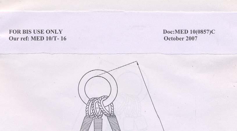
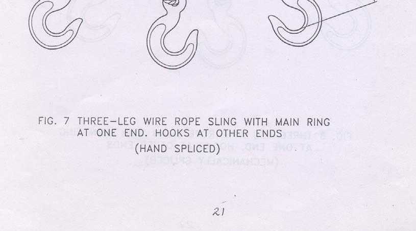
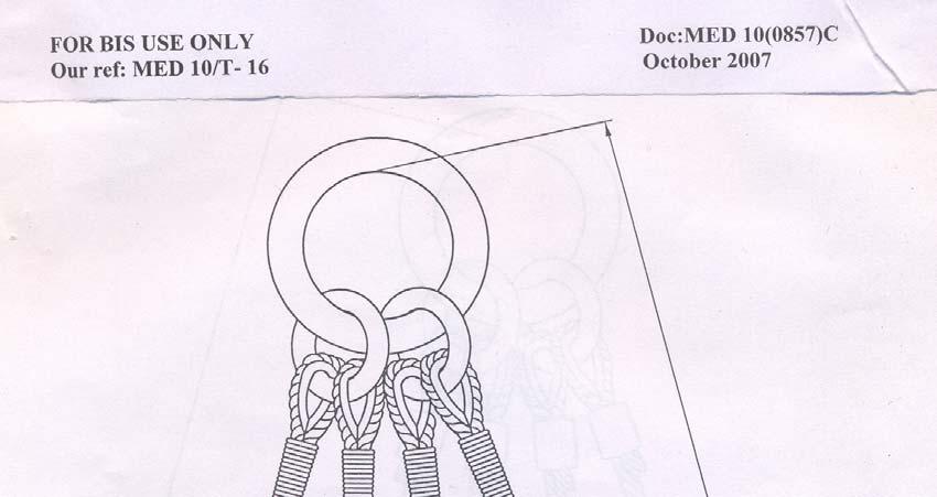
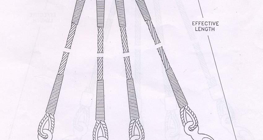
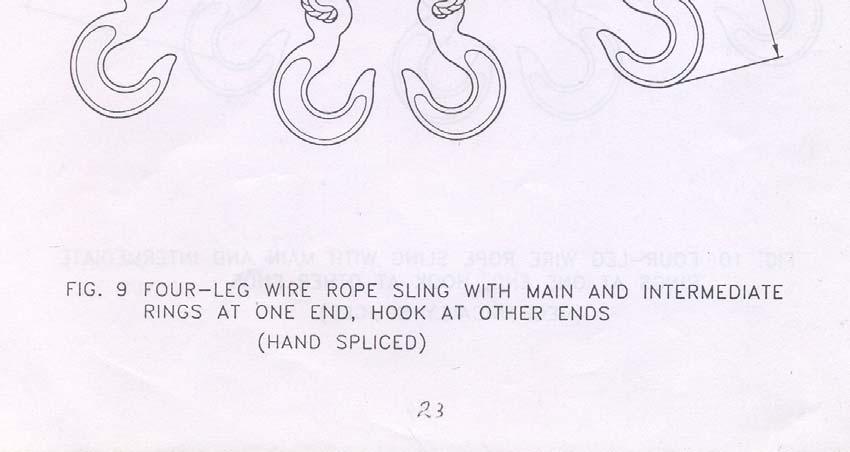
8 legs, intermediate seizing of above length shall be provided at intervals not greater than 72 times the diameter of the rope. 6.4 Safe Working Load The safe working load of a double part grommet sling for straight pull can be calculated as follows 2 x F o x K t SWL = x Zp F o : Minimum breaking force of the unit rope with fibre main core and wire tensile designation of 1770 whose strand is utilized in making the grommet K t : (0.80) Splicing efficiency factor : Constant for converting force unit (kn) into mass unit (tonne) used in lifting application Zp : (5) Co efficient of utilization 7 SLING ASSEMBLIES 7.1 The assembled slings shall be one of the forms shown in the figures 1 to 10. FIG 1 to Components Attachment The components for all slings shall be spliced or seized (as may be appropriate) directly to the sling leg, with the exception of four-leg slings, which shall comprise 2 two-leg assemblies complete with intermediate rings and a main ring. The welding and heat treatment of the rings shall be completed before the wire rope legs are attached.
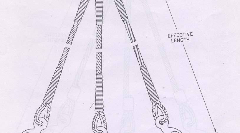
9 FOR BIS USE ONLY Doc:MED 10(0857)C Our ref: MED 10/T- 16 October Effective Length The effective length of all slings and sling legs shall be the length between the bearing points of their terminal components like thimble, ring or hook unless otherwise specified. The measurement shall be taken without applying any load. For multi leg slings the actual individual leg lengths shall not differ from the nominal length of the sling by more than two rope diameters or 1 percent of the nominal length whichever is greater. The difference in length between the individual legs of any multi leg sling shall not exceed 1.5 times rope diameter or 0.5 percent of the nominal length whichever is greater 8 TESTING Before assembly all rings and hooks shall be tested to a proof load which is equivalent to twice the safe working load. A sample of rope shall be tested according to IS After fabrication of sling, each sling leg shall be tested to a proof force which is equivalent to twice its safe working load 8.1 Extent of Manufacturing Proof Force Testing The manufacturing tests shall depend on whether the manufacturer has an applicable quality management system or not. The system shall comply with an internationally acceptable standard like IS/ISO 9001 and be certified by internationally accredited third party certification body. If such system is in place and operating, the test described in 7 shall be designated as type test and shall be carried out by the sling manufacturer as per their quality plan and shall be presented to the customer or his representative for verification whenever required. Every non-standard or oneoff sling assembly shall be tested in accordance with 7. 9 METHOD OF LOADING 9.1 The safe working load for slings as given in 4.3, 5.3 and 6.4 is for one sling under straight pull. Slings however can be utilized using different methods of loading as described in Annex A. The safe working load under each method of loading can be worked out using the appropriate factor given in Annex A. The safe working load and the proof load for the master ring may also be calculated under different conditions as given in 9.2 and After final heat treatment of the master ring and intermediate ring the slings with accessories shall be tested as an assembly. Multi leg wire rope slings shall, however, be tested in sections as given in Table 1. 9
10 Number of legs Angle of usage degrees Table 1 Safe Working Load (Clause 9.2) Safe Working Load Rope Master ring Intermediate ring Complete Assembly 1 0 W 1.0W - 1.0W 2 0 W 2.0W - 2.0W 90 W 1.4W - 1.4W 120 W 1.0W - 1.0W 2A W 2W cos A - 2W cos A 3 0 W 3.0W 1.0W 3.0W 90 W 2.1W 1.0W 2.1W 120 W 1.5W 1.0W 1.5W 2A W 3W cos A 1.0W 3W cos A A W W W W 4W 2.8W 2.0W 4Wcos A 1.0W 1.0W 1.0W 1.0W 4W 2.8W 2.0W 4Wcos A Remarks Critical Critical Critical A- Angle between any leg and the vertical line through the support point W- Safe working load 9.3 Proof Load Proof load for the rope, master ring, intermediate ring and the complete assembly shall be equal to double their respective safe working load for the angle of application, as given in MARKING 10.1 All slings shall be marked legibly on a) a durable metal label or a sleeve firmly attached to the sling, b) the body of the ferrule (without causing any damage) c) the master link (ring). with at least following information i) unique reference number identifying the sling with its test certificate, ii) the safe working load of the sling for single leg sling or the safe working load(s) to the leg angle(s) in case of multi leg sling. ii) month and year of manufacture related
11 FOR BIS USE ONLY Doc:MED 10(0857)C Our ref: MED 10/T- 16 October BIS certification Marking Each sling may also be marked with the Standard Mark The use of the Standard Mark is governed by the provisions of Bureau of Indian Standards Act, 1986 and the Rules and Regulations made there under. The details of conditions under which a license for the use of Standard Mark may be granted to the manufacturers or the producers may be obtained from the Bureau of Indian Standards 11 CERTIFICATE OF TEST AND EXAMINATION Every sling or batch of slings shall be provided with a test certificate issued by a competent person giving the following information: i) The name of the manufacturer/ supplier, ii) Full description of the sling, iii) The safe working load iv) Tested to proof load v) Date of test vi) Specification No : 11
12 Nominal rope diameter Single part (Single leg) Straight Choke pull hitch ANNEX A (Clause 9) SAFE WORKING LOAD AT DIFFERENT METHOD OF LOADING Double part endless and Two-leg Three-leg Four-leg Straight pull (1 No) grommet Choke hitch Straight pull (2 No.) 0 0 < α < α < α < α (mm) (t) (t) (t) (t) (t) (t) (t) (t) (t) (t) (t) (t) (t) Factor x Coefficient of utilization : 5 Angle subtended by the slings at the point of lifting : α Load (mass) for lifting : t (tonne)
13 April 2005 ANNEX B (Clause 1) GUIDELINES FOR USE OF SLINGS 1 Assess load to be lifted and its position of center of gravity. 2 Ensure that a proper sling is chosen for lifting the load. 3 Select the appropriate method of slinging. 4 The effective diameter are put should not be less than twice the diameter of rope. 5 While fitting eye termination particularly with thimble reinforcement to the lifting hook, ensure that it is seated properly without overcrowding. 6 Slings shall not be used for bending or strapping unless they are so designed for lifting purposes. 7 Avoid use of lang's lay rope for making sling. 8 Do not use hand spliced sling if it is likely to rotate during lifting the load. 9 Lift the load slowly avoiding jerk, shock etc. 10 Capacity of master link (ring) shall be at least equal to the capacity of the full sling. For intermediate link (ring) it shall be at least 1.4 times that of one sling leg. 11 For two or more leg sling, maximum permissible angle to the vertical for any sling leg shall not be more than 60 degrees. 12 Do not use sling beyond its permissible service temperature as given below : Type of splicing Mechanically spliced with A- ferrule Hand spliced Wire rope with Service temperature in 0 C Bearing capacity in percent Fibre core Steel core - 60 to Fibre core - 60 to to Steel core to
14 ANNEX C (Clause 1) DISCARD CRITERIA FOR SLINGS C-1 Presence of broken wires, excessive wear, mechanical and other damages due to heat, chemical reaction etc. are the main criteria for discarding a sling during use. Appearance of any of the following kinds of damage shall be a reason to withdraw a sling from the service: a) Broken strand b) Slackening under no load c) Crushing under no load d) Visible wire breakage at any point on a sling for a length of : 3 d four numbers 6 d six numbers 30 d sixteen numbers (where d = Diameter of rope) e) Crushing at the load bearing point of the eye along with four broken wires f) Kink formation g) Sign of corrosion h) Damage or undue wear at the eye termination

C")


15 FOR BIS USE ONLY Doc:MED 10(0857)C Our ref: MED 10/T- 16 October
16

C")


17 FOR BIS USE ONLY Doc:MED 10(0857)C Our ref: MED 10/T- 16 October
18

C")


19 FOR BIS USE ONLY Doc:MED 10(0857)C Our ref: MED 10/T- 16 October
20

C")


21 FOR BIS USE ONLY Doc:MED 10(0857)C Our ref: MED 10/T- 16 October
22

C")

23 FOR BIS USE ONLY Doc:MED 10(0857)C Our ref: MED 10/T- 16 October
24

C")


25 FOR BIS USE ONLY Doc:MED 10(0857)C Our ref: MED 10/T- 16 October
26

C")


27 FOR BIS USE ONLY Doc:MED 10(0857)C Our ref: MED 10/T- 16 October
28

C")


29 FOR BIS USE ONLY Doc:MED 10(0857)C Our ref: MED 10/T- 16 October
Guide to Documentation and Marking Part 5 Lifting Accessories, Slings
 Guide to Documentation and Marking Part 5 Lifting Accessories, Slings Document reference LEEA 059-5 version 1 dated 31.07.14 Introduction. This guide is aimed at manufacturers, distributors and users of
Proof load is the load applied in performance of a proof test. Proof test is a nondestructive tension test performed by the sling manufacturer or an
 1910.184 Slings (a) Scope. This section applies to slings used in conjunction with other material handling equipment for the movement of material by hoisting, in employments covered by this part. The types
GENERAL GUIDELINES FOR PROPER RIGGING PRACTICES AND INSPECTION & REMOVAL CRITERIA FOR SLINGS PER OSHA
 GENERAL GUIDELINES FOR PROPER RIGGING PRACTICES AND INSPECTION & REMOVAL CRITERIA FOR SLINGS PER OSHA 1910.184 SAFE OPERATING PRACTICES -.Whenever any sling is used, the following practices shall be observed:
3.1 T AND TKH FERRULES EUROPEAN STANDARD SYSTEM EN
 TURNBACK FERRULES T ferrule TKH ferrule 3.1 T AND TKH FERRULES EUROPEAN STANDARD SYSTEM EN 134113 GENERAL DESCRIPTION The aluminium ferrules, type T and type TKH correspond to the European standard for
Slings Steel Chain, Wire Rope and Metal Mesh
 Optional Information Name of School: Date of Inspection: Vocational Program/Course/Room: Signature of Inspector: Slings Steel Chain, Wire Rope and Metal Mesh Self Inspection Checklist Guidelines: This
Health & Safety Policy and Procedures Manual SECTION 25 RIGGING AND HOISTING EQUIPMENT
 SECTION 25 RIGGING AND HOISTING EQUIPMENT 1. RIGGING AND HOISTING: These rules apply to all Maul Electric, Inc. employees and subcontractors. Note: Maul Electric, Inc. employees will utilize mechanical
Lift-All Wire Rope & Slings
 WIRE ROPE AND SLING BASICS Lift-All & Slings Two major and opposing characteristics of wire rope slings are flexibility and resistance to abrasion. To a great extent, these traits are a direct function
Steel wire rope slings Safety
 BRITISH STANDARD BS EN 13414-3:2003 +A1:2008 Steel wire rope slings Safety Part 3: Grommets and cable-laid slings ICS 53.020.30 National foreword This British Standard was published under the authority
DEPARTMENT OF LICENSING AND REGULATORY AFFAIRS DIRECTOR'S OFFICE GENERAL INDUSTRY SAFETY STANDARDS PART 49. SLINGS
 DEPARTMENT OF LICENSING AND REGULATORY AFFAIRS DIRECTOR'S OFFICE GENERAL INDUSTRY SAFETY STANDARDS (By authority conferred on the director of the department of licensing and regulatory affairs by sections
Wire rope slings- and sling legs for general lifting purposes
 BS BS*KL290 83 lb24hbî 0339442. BS 1290: 1983 UDC 621.86.06 : 677.72 O British Standards nstitution. No part of this publication may be photocopied or otherwise reproduced without the prior permission
steel wire rope slings and fittings
 steel wire rope slings and fittings Steel Wire Rope Slings SNS7531 Working load limits using 6x19 or 6x36 IWR (1960mpa) SWR Ø nominal break load 1 Leg 2 Leg 3 and 4 Leg angle between the legs angle between
Visit: 27
 Visit: http://www.kwrs.com 7 SINGLE PART SLINGS Eyes are typically formed using a flemish eye splice. The ends are secured by pressing a metal sleeve over the ends of the strands of the splice. Pull follows
ISO INTERNATIONAL STANDARD. Cranes and lifting appliances Selection of wire ropes Part 1: General
 INTERNATIONAL STANDARD ISO 4308-1 Third edition 2003-05-01 Cranes and lifting appliances Selection of wire ropes Part 1: General Grues et appareils de levage Choix des câbles Partie 1: Généralités Reference
: : STANDARDIZATION ORGANIZATION FOR G.C.C (GSO) UAE.S GSO ISO :2007. Cranes and Lifting Appliances Selection of Wire Ropes Part 1 : General
 UAE.S GSO ISO :2007. Cranes and Lifting Appliances Selection of Wire Ropes Part 1 : General") STANDARDIZATION ORGANIZATION FOR G.C.C (GSO) UAE.S GSO ISO 4308-1:2007 ISO 4308-1:2003 : : Cranes and Lifting Appliances Selection of Wire Ropes Part 1 : General ICS : 53.020.30 Cranes and Lifting Appliances
STANDARDIZATION ORGANIZATION FOR G.C.C (GSO) UAE.S GSO ISO 4308-1:2007 ISO 4308-1:2003 : : Cranes and Lifting Appliances Selection of Wire Ropes Part 1 : General ICS : 53.020.30 Cranes and Lifting Appliances
Heavy Equipment Technician Rigging
 1. What is SWL? a. Single weight of load b. Second weakest location c. Working load limit Heavy Equipment Technician IP Red Seal Practice Exam d. Abbreviation for swivel Heavy Equipment Technician Rigging
tbs TDC8(5630)P 3 Draft Tanzania Standard Textiles Ropes Specifications: Part 2. Ropes made from Man-made fibres (First edition)
P 3 Draft Tanzania Standard Textiles Ropes Specifications: Part 2. Ropes made from Man-made fibres (First edition)") tbs TDC8(5630)P 3 Draft Tanzania Standard Textiles Ropes Specifications: Part 2. Ropes made from Man-made fibres (First edition) TANZANIA BUREAU OF STANDARDS 0. FOREWORD 0.1 The range of man-made fibre
tbs TDC8(5630)P 3 Draft Tanzania Standard Textiles Ropes Specifications: Part 2. Ropes made from Man-made fibres (First edition) TANZANIA BUREAU OF STANDARDS 0. FOREWORD 0.1 The range of man-made fibre
WIRE ROPE AND SLING BASICS. Total. of Wires WIRE ROPE SLINGS. Use of EIP, IWRC rope gives 15% greater capacity than IP, IWRC ropes.
 V WIRE ROPE AND SLING BASICS & Slings Two major and opposing characteristics of wire rope slings are flexibility and resistance to abrasion. To a great extent, these traits are a direct function of the
Ropes for Subsea Cable Laying
 Ropes for Subsea Cable Laying SEAMASTER CABLE LAID BUOY & GRAPNEL ROPES [ BUOY & GRAPNEL ] Cable Laid combined (wire and natural fibre) ropes specially designed for Subsea Cable Laying duties Designed
OMG Southeast & Southwest RIGGING SAFETY PROGRAM (29 CFR Part , , , , , & ANSI B30.5, ANSI B30.
 OMG Southeast & Southwest RIGGING SAFETY PROGRAM (29 CFR Part 1926.251, 1926.550, 1910.180, 1910.184, 1910.330, & ANSI B30.5, ANSI B30.8) Nearly every project is required to perform some type of rigging
Premium PowerPoint Presentation. Rigging Review
 Premium PowerPoint Presentation Rigging Review Chapter 1 Hoisting Safety Review: What about the CG Symmetrical vs. Asymmetrical Balanced and Unbalanced Lifting Lug Hooks Angle Deformation Safety Gates
1.0 Purpose: To provide guidelines for selection, usage, inspection and rejection of rigging equipment
 Orignal Issue Date : 28-10-10 Date of Revision: Page- - 1-1.0 Purpose: To provide guidelines for selection, usage, inspection and rejection of rigging equipment (Slings & Ropes) 2.0 Reference: 3.0 Associated
ISO INTERNATIONAL STANDARD. Steel wire ropes for the petroleum and natural gas industries Minimum requirements and terms of acceptance
 INTERNATIONAL STANDARD ISO 10425 First edition 2003-08-15 Steel wire ropes for the petroleum and natural gas industries Minimum requirements and terms of acceptance Câbles en acier pour les industries
Fall Protection Checklist. Guardrail System
 Fall Protection Checklist Location/Department: Date of Inspection: Inspectors: Corrective Actions: Work order/memos were issued: Yes No Date issued: In accordance with the MIOSHA and OSHA standards the
CORPORATE SAFETY MANUAL
 CORPORATE SAFETY MANUAL Procedure No. 32-0 Revision: Date: May 2005 Total Pages: 10 PURPOSE To provide general guidelines for the inspection of all ropes, chains, cables, slings, etc. used for personnel
ISO 4344 INTERNATIONAL STANDARD. Steel wire ropes for lifts Minimum requirements. Câbles en acier pour ascenseurs Exigences minimales
 INTERNATIONAL STANDARD ISO 4344 Second edition 2004-02-01 Steel wire ropes for lifts Minimum requirements Câbles en acier pour ascenseurs Exigences minimales Reference number ISO 2004 PDF disclaimer This
Standard Specification for Stranded Carbon Steel Wire Ropes for General Purposes 1
 Designation: A 02/A 02M 0 Standard Specification for Stranded Carbon Steel Wire Ropes for General Purposes This standard is issued under the fixed designation A 02/A 02M; the number immediately following
GENERAL INFORMATION WIRE ROPE SLINGS
 GENERAL INFORMATION NOMINAL SLING STRENGTH is based upon the nominal (catalog) rope strength of the wire rope used in the sling and other factors which affect the overall strength of the sling. These other
MATERIAL HANDLING - FIELD RIGGING SAFETY PROGRAM
 Title: Material Handling - Rigging Effective Date: 12/4/2014 Control Number: THG_0049 Revision Number: 1 Date: 10/23/2015 Annual Review Completed: 5/13/2015 MATERIAL HANDLING - FIELD RIGGING SAFETY PROGRAM
BANKSMAN / SLINGER. 1. What is the smallest size diameter of synthetic rope allowed for use as a hand held tagline?
 BANKSMAN / SLINGER 1. What is the smallest size diameter of synthetic rope allowed for use as a hand held tagline? A. 16mm B. 10mm C. 12mm 2. What is the maximum temperature that a webbing sling can be
NEVER EXCEED WORKING LOAD LIMITS PAGE
 WIRE ROPE All wire rope is manufactured with three basic components: Wires, Strand and Core. Following is a description on the essential information required for ordering wire rope. DIAMETER Nominal Diameter
Care, Use and Inspection
 Care, Use and Inspection of Synthetic Web Slings Safety is the paramount consideration involved in the use of any web sling. This standard does not purport to address all safety concerns, if any, associated
ISO INTERNATIONAL STANDARD. Personal protective equipment for protection against falls from a height Single-point anchor devices
 INTERNATIONAL STANDARD ISO 14567 First edition 1999-03-01 Personal protective equipment for protection against falls from a height Single-point anchor devices Équipements individuels de protection contre
Draft Indian Standard SAFES Part 2 Tests for Burglary Resistance (Fifth Revision)
") Draft For Comments Only Draft Indian Standard SAFES Part 2 Tests for Burglary Resistance (Fifth Revision) Not to be reproduced without the permission of Last date for receipt of BIS or used as a STANDARD
Draft For Comments Only Draft Indian Standard SAFES Part 2 Tests for Burglary Resistance (Fifth Revision) Not to be reproduced without the permission of Last date for receipt of BIS or used as a STANDARD
LiftAlloy TM Chain Slings
 LiftAlloy TM LiftAlloy CHAIN SLING BASICS Lift-All chain slings meet or exceed all OSHA, ASME B30.9 and NACM standards and regulations LiftAlloy chain slings, available in grade 00 for 7/32" through 3/4",
Standard Specification for Stranded Carbon Steel Wire Ropes for General Purposes 1
 Designation: A02/A02M 0 Standard Specification for Stranded Carbon Steel Wire Ropes for General Purposes This standard is issued under the fixed designation A02/A02M; the number immediately following the
AUSTRALIAN LIFTING CENTRE PTY LTD
 AUSTRALIAN LIFTING CENTRE PTY LTD 1300 100 120 WWW.AUSTLIFT.COM.AU LIFTING YOUR BUSINESS TO A HIGHER LEVEL Contents 1x19 Construction 153 7x7 Construction 154 7x19 Construction 154 PVC Coated 6x19 + FC
Drawing Showing the Component Parts of a Standard Steel Wire Rope
 Drawing Showing the Component Parts of a Standard Steel Wire Rope Core wire Rope wire Strand Steel wire rope Core of natural or synthetic fibre or steel * *) The strands are wrapped around a core of fibre
Draft Indian Standard CYCLE BICYCLE FOR GENERAL PURPOSE SPECIFICATION
 For comments only Draft Indian Standard CYCLE BICYCLE FOR GENERAL PURPOSE SPECIFICATION Not to be reproduced or used as a STANDARD without the permission of BIS Last Date for comments: 30 September 2011
INSTALLATION PROCEDURE FOR OPGW FIBER OPTIC CABLES
 Page 1 of 15 INSTALLATION PROCEDURE FOR OPGW FIBER OPTIC CABLES Page 2 of 15 1. PURPOSE 2. SCOPE 3. REFERENCES 4. GENERAL INDEX 5. PROCEDURES 5.1 Line survey 5.2 Transport, loading, unloading and storage
PURPOSE: The purpose of this Operating Policy/Procedure (OP) is to ensure that material handling devices are used correctly and safely.
 is to ensure that material handling devices are used correctly and safely.") [Date changed posted 10/3/17 (replaces 10/31/12 edition)] Operating Policy and Procedure : Material Handling Devices DATE: October 3, 2017 PURPOSE: The purpose of this Operating Policy/Procedure (OP) is
[Date changed posted 10/3/17 (replaces 10/31/12 edition)] Operating Policy and Procedure : Material Handling Devices DATE: October 3, 2017 PURPOSE: The purpose of this Operating Policy/Procedure (OP) is
WEB SLING BASICS AND HOW TO ORDER WEB SLINGS
 27 WEB SLING BASICS AND HOW TO ORDER WEB SLINGS TYPE I Web sling made with a triangle fitting on one end and a slotted triangle choker fitting on the other end. It can be used in a vertical, basket or
Roughneck TM Mesh Slings
 Roughneck TM Slings ROUGHNECK WIRE MESH SLINGS Widely used in metalworking shops and steel warehouses where loads are abrasive, hot or tend to cut web slings Features and Benefits Promotes Safety Steel
ISO INTERNATIONAL STANDARD. Pulps Determination of drainability Part 1: Schopper-Riegler method
 Provläsningsexemplar / Preview INTERNATIONAL STANDARD ISO 5267-1 Second edition 1999-03-01 Pulps Determination of drainability Part 1: Schopper-Riegler method Pâtes Détermination de l'égouttabilité Partie
Suspension Ropes. Suspension Rope
 Suspension Ropes IMechE CPD Certificate Course 23 Nov. 2016 Suspension Rope Standard Configuration Replacement Criteria Tension Measurement Traction Measurement Standard Nominal diameter at least 8mm BS302
"RIGGING SAFETY IN CONSTRUCTION ENVIRONMENTS"
 PRESENTER'S GUIDE "RIGGING SAFETY IN CONSTRUCTION ENVIRONMENTS" Part of the "CONSTRUCTION SAFETY KIT" Series Quality Safety and Health Products, for Today...and Tomorrow OUTLINE OF MAJOR PROGRAM POINTS
September 27, DOE-RL-92-36, Hanford Site Hoisting and Rigging Manual. Wire Rope. Page 1 CONTENTS
 Page 1 CONTENTS 8.0 WIRE ROPE...2 8.1 SCOPE...2 8.2 GENERAL REQUIREMENTS...2 8.2.1 Design Factors For s... 2 8.2.2 Rotation-Resistant Rope...3 8.2.3 Requirement for Independent Core...3 8.3 INSPECTION
MoBiLe CrAnes. surelift. B y W i r e r o p e i n d u s t r i e s. tower CrAnes. port CrAnes
 MoBiLe CrAnes tower CrAnes overhead CrAnes port CrAnes 004-14-201-WR203-06/00 Printed in Canada on Recycled Paper performance series performance series ropes For MuLti-purpose AppLiCAtions Backed by over
Straddle Carrier RTG. Port Industry
 Harbor Mobile Crane Gantry / STS Crane Straddle Carrier RTG Port Industry Port Industry applications verope offers various ropes, rope end fittings and customized solutions for port industry applications.
Basic Rigging And Wire Rope
 Basic Rigging And Wire Rope Presented By Master Builders of Iowa Basic Rigging and Wire Rope Topics Four Commandments of Rigging Sling Angles Types Of Hitches Types Of Slings Types Of Rigging Devices OSHA
FOR MORE INFORMATION CONTACT OUR NEAREST BRANCH OFFICE
 1 SECTION 1 - Wire Rope WIRE ROPE General Information Terminology & Properties Terminology With precise, moving parts, designed and manufactured to bear definite relationship to one another, Wire Rope
Care, Use & Maintenance of Wire Ropes on Cranes
 Care, Use & Maintenance of Wire Ropes on Cranes Dr. Frank Jauch Global Product Manager Crane Ropes WireCoWorldGroup Kansas City/MO USA Our partner in Australia The company was founded in 1948 CASAR Ropes
Courtesy of Loos & Co., Inc.
 INCH-POUND 22 December 2015 SUPERSEDING RR-W-410G 24 June 2010 FEDERAL SPECIFICATION WIRE ROPE AND STRAND The General Services Administration has authorized the use of this federal specification by all
ELEPHANT COMPACTED ROPE
 ELEPHANT COMPACTED ROPE With brilliant recent advancements in various industrial machines and facilities, ropes used in industrial facilities are required highly improved quality and performance. Responding
Chapter 2 Rigging. Cutting Wire Rope. Anchoring Wire Rope to Drum. Winding Wire Rope Onto Drum
 Chapter 2 Rigging Cutting Wire Rope The wire rope must be tightly seized on both sides of the point where the wire rope will be cut, as shown in Figure 2-1. Seize the wire rope with either seizing wire
Wire Rope. Section One. Section One
 DM Standen Ltd has been supplying and distributing wire rope since 1978. Apart from the distribution of wire rope, our personnel can supply guidance to users on the correct usage and selection of wire
Winchline n a box WINCH LINE SELECTION GUIDE. Wire Rope Winchlines are superior to most other winchlines found in the market place due to the
 Winchline n a box Wire Rope Winchlines are superior to most other winchlines found in the market place due to the eye) end terminations. Each eye is protected by a steel liner (thimble) to guard against
LiftAlloy Chain Slings
 CHAIN SLING BASICS Slings Lift-All chain slings meet or exceed all OSHA, ASME B30.9 and NACM standards and regulations. chain slings, available in 80 for 7/8"- /4" and 00 for 7/32"-3/4", are recommended
The team of professionals at ASAHI aims to provide our customers the best of the products and the highest level of services.
 One ropemultiple applications ASAHI ROPES PRIVATE LIMITED was established in Delhi way back in 986 by the people with a vast experience in the field of manufacturing and marketing of steel wire ropes and
Technical Briefing Note
 Technical Briefing Note Subject Date Issued Revision Glossary of Terms 14th Nov 2017 Rev 3 The purpose of this Technical Briefing Note is to provide a glossary of terms commonly used in fall injury prevention
SAMPLE PAGE. Section 2... Wire Rope
 Section 2...................................................... Wire Rope Never use any kind of clip to directly connect two straight lengths of wire rope to form a continuous piece. Do not make up slings
STANDARD SPECIFICATION FOR SPLIT TEES (HOT TAP MATERIAL)
") STANDARD SPECIFICATION FOR SPLIT TEES (HOT TAP MATERIAL) TEE (HOT TAPPING MATERIAL) S-04-02-040 Page 1 of 7 1.0 SCOPE This specification covers the basic requirements for the design, manufacture and supply
STANDARD SPECIFICATION FOR SPLIT TEES (HOT TAP MATERIAL) TEE (HOT TAPPING MATERIAL) S-04-02-040 Page 1 of 7 1.0 SCOPE This specification covers the basic requirements for the design, manufacture and supply
Detailed Instructions for the use of Wirelock
 Detailed Instructions for the use of Wirelock With Strand or General Purpose Wire Rope These instructions explain the proper use of WIRELOCK for socketing wire rope terminations. When reading and following
For Review Only No Copying No Saving No Lending No Posting Online
 The following copyrighted samples are provided as a service for your review only. Copying, saving, lending, posting online or any general use of these files other than for the purpose provided is unlawful
TECH TIPS: ROPE DEFECTS
 Hoist Ropes: Why must they be inspected? A hoist rope is not made to last forever. This is a useful fact, as the kinds of wear that appear on a rope can indicate areas of problems within an installation
FEDERAL SPECIFICATION WIRE ROPE AND STRAND
 INCH-POUND 6 December 2007 SUPERSEDING RR-W-410E 7 February 2002 FEDERAL SPECIFICATION WIRE ROPE AND STRAND The General Services Administration has authorized the use of this federal specification by all
SECTION 15 RIGGING. b. Defective rigging shall be removed from service.
 SECTION 15 RIGGING 15.A GENERAL 15.A.01 Inspection and use. a. Rigging equipment shall be inspected as specified by the manufacturer, by a Competent Person, before use on each shift and as necessary during
Height Safety Lifting Load Control
 01 Safety Height Safety Lifting Load Control Management SPECIALISED LANYARDS Technical Data Sheet SpanSet Australia Ltd 150 Old Bathurst Road Emu Plains NSW 2750 Australia Telephone +61 2 4735 3955 Fax
Liquefied gas cargo tanks and process pressure vessels
 .1 -.3 Liquefied gas cargo tanks and process pressure vessels.1 General.1.1 The present texts give the general principles which are applied by Classification Societies for approval and survey of the relevant
Pressure Equipment Directive PED 2014/68/EU Commission's Working Group "Pressure"
 I. MISCELLANEOUS Guideline I-01 Guideline related to: Article 4 paragraph 3 What is to be understood by "sound engineering practice"? Sound engineering practice means, without prejudice to Article 5, paragraph
IAPMO GUIDE CRITERIA FOR BALL VALVES IAPMO IGC PURPOSE
 INTERNATIONAL ASSOCIATION OF PLUMBING AND MECHANICAL OFFICIALS IAPMO GUIDE CRITERIA FOR BALL VALVES IAPMO IGC 157-20067 1 PURPOSE 1.1 The purpose of this standard is to establish an acceptable standard
Managing Mobile Crane Hazards. Paul Satti Construction Safety Council. Hazards of Working Around Cranes. Key Concepts:
 Managing Mobile Crane Hazards Paul Satti Construction Safety Council Hazards of Working Around Cranes Key Concepts: Electrocution Hazards Caught-In, Compressed or Crushing Hazards Struck-By Hazards Other
Splicing Instructions. Moran Tuck Splice
 Splicing Instructions Moran 5-4-3 Tuck Splice Introduction Moran 5-4-3 Tuck Splice This document describes the steps required to perform a Moran 5-4-3 Tuck Splice. The Moran 5-4-3 Tuck Splice is a Cortlandapproved
Technical Literature. Plasma. 12x12 Sling Inspection Guidelines
 Technical Literature Plasma 12x12 Sling Inspection Guidelines Plasma 12x12 Ropes Lifting Slings Made From Plasma 12x12 Ropes Plasma 12x12 ropes are excellent lightweight lifting tools providing reliable,
Fall Protection- Part 2
 Optional Information Name of School: Date of Inspection: Vocational Program/Course/Room: Signature of Inspector: Fall Protection- Part 2 Self Inspection Checklist Instructions: This checklist covers fall
Hangt de baggerindustrie aan een (zijden) draadje
 draadje") Lloyd s Register: Business unit Marine Hangt de bagger industrie aan een (zijden) draadje Door: Cor Dekker Senior Specialist Marine Equipment & Lifting Components The Group at a glance 278 offices delivering
Lloyd s Register: Business unit Marine Hangt de bagger industrie aan een (zijden) draadje Door: Cor Dekker Senior Specialist Marine Equipment & Lifting Components The Group at a glance 278 offices delivering
Overview (key points)
") Topic / Subject TYPE 1 FALL-ARREST DEVICES Time frame = mins Contact statement (gain student attention and create a readiness to learn) Overview (key points) Purpose -Fall-arrest devices are designed to
Topic / Subject TYPE 1 FALL-ARREST DEVICES Time frame = mins Contact statement (gain student attention and create a readiness to learn) Overview (key points) Purpose -Fall-arrest devices are designed to
LOAD HUGGER CARGO CONTROL
 Hugger BASICS Lift-All Hugger cargo control and load securement products are of the highest quality. They offer the van and flatbed operator a wide variety of options to meet Department of Transportation
KATRADIS MARINE ROPES INDUSTRY S.A.
 KATRADIS MARINE ROPES INDUSTRY S.A. USER S MANUAL MOORING TAILS -NIKA-Nylon -NIKA-Polyester -Mixed Polyester/Nikasteel REV 1.0 Page 1 USER S MANUAL The use of mooring tails is highly recommended with low
This document is a preview generated by EVS
 EESTI STANDARD EVS-EN 12385-6:2004 Steel wire ropes - Safety - Part 6: Stranded ropes for mine shafts Steel wire ropes - Safety - Part 6: Stranded ropes for mine shafts EESTI STANDARDIKESKUS EESTI STANDARDI
HOW TO PREPARE FOR THE LEVEL A CRANESAFE CERTIFICATION ASSESSMENT
 HOW TO PREPARE FOR THE LEVEL A CRANESAFE ASSESSMENT Prepare for your assessment! Our website contains all the information you need for a successful assessment. Our goal is to find you competent on the
Commercial Chain & Fittings
 Commercial Chain & Fittings 2 IWR Lifting PW Anchor Herc-Alloy 800 The most effective link from the factory floor to the farm esigned to solve almost any suspending, mooring or fencing challenge, PW Anchor
SLINGS, HOISTING & RIGGING
 GENERAL REQUIREMENTS These requirements apply regarding the hazards associated with hoisting and rigging. Pre-shift Visual Inspection of Cranes Cranes being used in steel erection activities will be visually
Crosby: There is No Equal
 Forged Clips The Market Leader: Yesterday, Today and Tomorrow G-450 G-429 Crosby: There is No Equal FORGED FOR CRITICAL APPLICATIONS The proper performance of forged clips depends on proper manufacturing
DOCUMENT DESPATCH ADVICE Ref: MED 16 :1/T- 6 Date:
 RAFT TANAR IN WIE IRUATION OUMENT EPATH AVIE Ref: ME 16 :1/T- 6 ate: 18-2-215 Gas ylinders, ectional ommittee, ME 16 TO: a) The interested members of Mechanical Engineering ivision ouncil, ME b) All members
Pressure Equipment Directive PED 2014/68/EU Commission's Working Group "Pressure"
 H. INTERPRETATION OF OTHER ESSENTIAL SAFETY REQUIREMENTS Guideline H-02 Guideline related to: Annex I Section 3.2.2 and 7.4 Final assessment (Annex I Section 3.2.2) of pressure equipment must include a
TECHNICAL CIRCULAR. Circular No: S-P 32/13 Revision: 1 Page: 1 of 7 Date:
 Circular No: S-P 32/13 Revision: 1 Page: 1 of 7 Date:22.05.2014 Related Requirement: UR S27 (Rev.6 June 2013) Subject: Retroactive Application for Strength Requirements for Fore Deck Fittings and Equipment
Crane & Rigging Brain Teasers
 Crane & Rigging Brain Teasers Host: Mike Parnell President/CEO, ITI ASME B30 Vice Chair (Cranes & Rigging) ASME P30 Chair (Lift Planning) The views expressed in this presentation are that of ITI and are
LIFTING RANGE WLL FEATURES CONTENTS. Height Safety Lifting Load Control Safety Management. BS EN (Web Sling) Roundslings
 Roundslings") CONTENTS FEATURES Roundslings pg BS (Web Sling) (E) Econolift roundsling (S) SupraPlus roundsling (MG) Magnum roundsling EN19- BS EN19- (Roundsling) Working load Limit (in metric tonnes) (MGX) Magnum X
CONTENTS FEATURES Roundslings pg BS (Web Sling) (E) Econolift roundsling (S) SupraPlus roundsling (MG) Magnum roundsling EN19- BS EN19- (Roundsling) Working load Limit (in metric tonnes) (MGX) Magnum X
Revisions to the Regulations for Agility Trials
 Revisions to the Regulations for Agility Trials Effective January 2, 2018 Equipment changes may be done prior to January 2, 2018, but must be completed by January 2, 2018 This insert is issued as a supplement
ISO INTERNATIONAL STANDARD. Personal fall-arrest systems Part 1: Full-body harnesses
 INTERNATIONAL STANDARD ISO 10333-1 First edition 2000-07-01 Personal fall-arrest systems Part 1: Full-body harnesses Systèmes individuels d'arrêt de chute Partie 1: Harnais complet Reference number ISO
steel wire rope for lifting machines
 steel wire rope for lifting machines 19x7+IWRC 18x7+FC made to EN12835 specifications lay-up of wires 1-6 SWR dia 19x7+IWRC Minimum breaking load 18x7+FC Minimum breaking load 1770 N/mm² 1960 N/mm² 2160
Moor, Tend Mooring And Unmoor Ship - Supervisor Level -
 Marine Terminal Operations Competency Standard Moor, Tend Mooring And Unmoor Ship - Supervisor Level - Industry : Oil, Chemical and Gas Industry Competency Category : 2.0 Moor, tend mooring and unmoor
Warning CABLE REPLACEMENT INSTRUCTIONS. Questions? - Call Telpro Inc. Customer Service at or
 CABLE REPLACEMENT INSTRUCTIONS Warning Read and follow these warnings and the instructions that follow. Failure to do so could result in serious property damage and/or serious bodily injury. BEFORE operating
Distribution. Experience Matters.
 Distribution Experience Matters. Steel Wire Rope Steel Wire Rope Slings The Partnership Usha Martin a leading manufacturer of a wide and diverse range of quality wire ropes suited for almost all applications.
GUNNEBO INDUSTRIES LIFTING SHACKLES
 GUNNEBO INDUSTRIES LIFTING SHACKLES USER S INSTRUCTIONS AND EC DECLARATION OF CONFORMITY Original instructions according to Directive 2006/42/EC on machinery, section 1.7.4 Instructions, and Annex II.1.A.
List of Material Rope Courses FLEXIBLE PFEIFER SEIL- UND HEBETECHNIK GMBH
 09/2014 R O T FLEXILE S U SEIL- UND HEETECHNIK GMH List of Material Rope Courses DR.-KARL-LENZ-STRASSE 66 D-87700 MEMMINGEN TELEPHONE +49 (0) 83 31-937-267 TELEFAX +49 (0) 83 31-937-341 E-MAIL wireropes@pfeifer.de
SPECIAL WIRE ROPES THE ADVANCED LINE
 SPECIAL WIRE ROPES THE ADVANCED LINE INTRODUCTION Quality Products, Outstanding Service and Comprehensive Technical Support It s what today s industries expect from their supplier partners. And that s
Related Elevator Products
 37 SECTION 2 - Elevator Products Reeving Splices Related Elevator Products Reeving Splice Specifications PIN # Wire Rope Size Units per Carton Wt. per Carton (Lbs) Length (IN) Color Code 1119100012 3/8
DLH online. Important factors in the selection of lifting slings
 DLH online 10 Important factors in the selection of lifting slings Tel: 0845 270 2919 - INT: 00 44 161 223 1990 - Email: sales@dale-lifting.co.uk - Web: www.dlhonline.co.uk 1 WHAT YOU NEED TO KNOW? Choosing
Rigging Safety. 1 Copyright 2014 by PEC Safety Management, Inc. PPT-SM-RIGGING 2014
 Rigging Safety 1 Copyright by PEC Safety Management, Inc. Rigger Role Assist the crane operator by properly attaching and detaching loads the crane Know how to safely connect and disconnect loads Discuss