Upgrade Increased Seaming Spindle Bushing Wear Life & Repair Suggestion
|
|
|
- Lynette Norton
- 5 years ago
- Views:
Transcription
1 10 Ascot Parkway Cuyahoga Falls, OH USA 330/ fax 330/ Upgrade Increased Seaming Spindle Bushing Wear Life & Repair Suggestion Bulletin: # December 15, 1995 Seamers Affected: 2003, 2004, 2006 Closers & Seamers Upgrade Description A material change has been made to the seaming spindle bushing which will increase the wear life of both the spindle and the bushing. The new bushing material will be more compatible with the stainless steel seaming spindle that has been used for several years now. this is especially true when there is a bushing failure due to loss of lubrication film sometimes experienced with manual lube systems. As a reminder, the maximum recommended grease interval for the spindle bearings is 8 hours. Shorter grease interval times can increase wear life of these bearings especially under severe conditions. Corrective Action: Replace old bushing part number with new part number as listed below. Old Part Number: Bushing-Spindle New Part Number: Bushing-Spindle NOTE: When replacing new bushings and especially if a new spindle is included, to avoid a time consuming run-in period, we suggest the initial greasing of the bushings to include a light mixture of grease and Time Saver (Yellow Label #60 medium grade). This is a one time application and not to be repeated after machine is placed in production
2 10 Ascot Parkway Cuyahoga Falls, OH USA 330/ fax 330/ Upgrade Increased Seaming Spindle Bushing Wear Life & Repair Suggestion Bulletin: # December 15, 1995 Seamers Affected: 2003, 2004, 2006 Closers & Seamers Upgrade Description A material change has been made to the seaming spindle bushing which will increase the wear life of both the spindle and the bushing. The new bushing material will be more compatible with the stainless steel seaming spindle that has been used for several years now. this is especially true when there is a bushing failure due to loss of lubrication film sometimes experienced with manual lube systems. As a reminder, the maximum recommended grease interval for the spindle bearings is 8 hours. Shorter grease interval times can increase wear life of these bearings especially under severe conditions. Corrective Action: Replace old bushing part number with new part number as listed below. Old Part Number: Bushing-Spindle New Part Number: Bushing-Spindle NOTE: When replacing new bushings and especially if a new spindle is included, to avoid a time consuming run-in period, we suggest the initial greasing of the bushings to include a light mixture of grease and Time Saver (Yellow Label #60 medium grade). This is a one time application and not to be repeated after machine is placed in production
3 10 Ascot Parkway Cuyahoga Falls, OH USA 330/ fax 330/ Upgrade Increased Seaming Spindle Bushing Wear Life & Repair Suggestion Bulletin: # December 15, 1995 Seamers Affected: 2003, 2004, 2006 Closers & Seamers Upgrade Description A material change has been made to the seaming spindle bushing which will increase the wear life of both the spindle and the bushing. The new bushing material will be more compatible with the stainless steel seaming spindle that has been used for several years now. this is especially true when there is a bushing failure due to loss of lubrication film sometimes experienced with manual lube systems. As a reminder, the maximum recommended grease interval for the spindle bearings is 8 hours. Shorter grease interval times can increase wear life of these bearings especially under severe conditions. Corrective Action: Replace old bushing part number with new part number as listed below. Old Part Number: Bushing-Spindle New Part Number: Bushing-Spindle NOTE: When replacing new bushings and especially if a new spindle is included, to avoid a time consuming run-in period, we suggest the initial greasing of the bushings to include a light mixture of grease and Time Saver (Yellow Label #60 medium grade). This is a one time application and not to be repeated after machine is placed in production
4 10 Ascot Parkway Cuyahoga Falls, OH USA 330/ fax 330/ Upgrade , , New Design of the Vertical Filler Drive Shaft Bulletin: # May 9, 1996 (Revised) Seamers Affected: 2100, 2010, 2150, 2200 Closers Upgrade Description A new Vertical Filler Drive Shaft has been designed due to difficulties encountered in removing the shaft upwards for field repairs. The new shaft design eliminates the need to remove the Chain Drive Housing which facilitates removal and installation of new gears. The lower end of the shaft has been shortened and the upper end has a relief cut in it for clearance for ease of removal. The lower retaining washer has also been modified due to the shortening of the shaft. Do not reuse the old retaining washer as severe damage will occur. A new bolt to hold the new retainer washer is also necessary as the old bolt will be too short. Corrective Action: Replace the old Shaft-Filler Drive Vertical and the Washer-Shaft Retaining part numbers with the new part numbers as listed below. Old Part Number: Vertical Filler Drive Shaft Washer-Shaft Retaining Bolt-Hex Hd. 1/2-13 x 1-1/4 New Part Number: Vertical Filler Drive Shaft Washer-Shaft Retaining Bolt-Hex Hd. 1/2-13 x 2-1/2 Seamers Affected: Group Assemblies: Seamers Affected: Group Assemblies: M M M M M M
5 10 Ascot Parkway Cuyahoga Falls, OH USA 330/ fax 330/ Upgrade , , New Design of the Vertical Filler Drive Shaft Bulletin: # May 9, 1996 (Revised) Seamers Affected: 2100, 2010, 2150, 2200 Closers Upgrade Description A new Vertical Filler Drive Shaft has been designed due to difficulties encountered in removing the shaft upwards for field repairs. The new shaft design eliminates the need to remove the Chain Drive Housing which facilitates removal and installation of new gears. The lower end of the shaft has been shortened and the upper end has a relief cut in it for clearance for ease of removal. The lower retaining washer has also been modified due to the shortening of the shaft. Do not reuse the old retaining washer as severe damage will occur. A new bolt to hold the new retainer washer is also necessary as the old bolt will be too short. Corrective Action: Replace the old Shaft-Filler Drive Vertical and the Washer-Shaft Retaining part numbers with the new part numbers as listed below. Old Part Number: Vertical Filler Drive Shaft Washer-Shaft Retaining Bolt-Hex Hd. 1/2-13 x 1-1/4 New Part Number: Vertical Filler Drive Shaft Washer-Shaft Retaining Bolt-Hex Hd. 1/2-13 x 2-1/2 Seamers Affected: Group Assemblies: Seamers Affected: Group Assemblies: M M M M M M
6 10 Ascot Parkway Cuyahoga Falls, OH USA 330/ fax 330/ Seaming Roll Shield Update (ECN ) Bulletin: Seamers Affected: # May 9, UHCM Closers Upgrade Description During the 204 conversions on the 3200 UHCM there were reports that there was roll to roll interference between the Seaming Roll Shields. We modified the existing shields on customer machines during the conversions and revised the parts we had in stock as per the drawing below. There is a possibility that Seaming Roll Shields that were in customer inventory may not have been modified. Corrective Action: Machine any Seaming Roll Shields (P/N ) that are in stock to the dimension show in the drawing.
7 10 Ascot Parkway Cuyahoga Falls, OH USA 330/ fax 330/ Seaming Roll Shield Update (ECN ) Bulletin: Seamers Affected: # May 9, UHCM Closers Upgrade Description During the 204 conversions on the 3200 UHCM there were reports that there was roll to roll interference between the Seaming Roll Shields. We modified the existing shields on customer machines during the conversions and revised the parts we had in stock as per the drawing below. There is a possibility that Seaming Roll Shields that were in customer inventory may not have been modified. Corrective Action: Machine any Seaming Roll Shields (P/N ) that are in stock to the dimension show in the drawing.
8 10 Ascot Parkway Cuyahoga Falls, OH USA 330/ fax 330/ Upgrade New Design of Cover Feed Screw Separator Bulletin: # October 10, 1996 Seamers Affected: 449, 450, 490, 2003, 2004, 2006 Closer & Seamers Upgrade Description A new Cover Feed Screw Separator was designed approximately three years ago which is designed to facilitate running the new light weighted ends that are currently bing used. The new part has a revised separation lead which is much better suited to running the new style ends. The duration of separation angle has been increased thereby eliminating the end curl damage that can occur with the old style Separator. Note in the figure below the increased separation angle on the new style Separator shown on the right. OPEN Old Style Separator Many customers have found this new Separator extremely helpful for running 75# and under ends. The new separator will also run the heavy base weight ends. the new Cover Feed Screw Separator supersedes the old part so the old part is no longer available. Corrective Action: Replace old Cover Feed Screw Separator part number with new part number as listed below. You can not run the old Separator with the new style Separator in the same Cover Feed Assembly. All Cover Feed Screw Assemblies must be updated at the same time or jamming of the Cover Feed is likely with possible damage occurring to the new Cover Feed Screw Separators. Old Part Number: Cover Feed Screw Separator New Part Number: Cover Feed Screw Separator New Style Separator NOTE: When replacing the Cover Feed Screw Separator on some old Cover Feed Screws you will encounter a dowel pin which must be removed. This pin can be either pulled out or ground off whichever is easier. The dowel pin serves no purpose since the counter sink of the screws align the assembly. The square hole that existed in the old Separators caused problems with flatness during heat treating and added unnecessary cost to the part.


9 10 Ascot Parkway Cuyahoga Falls, OH USA 330/ fax 330/ Upgrade New Design of Cover Feed Screw Separator Bulletin: # October 10, 1996 Seamers Affected: 449, 450, 490, 2003, 2004, 2006 Closer & Seamers Upgrade Description A new Cover Feed Screw Separator was designed approximately three years ago which is designed to facilitate running the new light weighted ends that are currently bing used. The new part has a revised separation lead which is much better suited to running the new style ends. The duration of separation angle has been increased thereby eliminating the end curl damage that can occur with the old style Separator. Note in the figure below the increased separation angle on the new style Separator shown on the right. OPEN Old Style Separator Many customers have found this new Separator extremely helpful for running 75# and under ends. The new separator will also run the heavy base weight ends. the new Cover Feed Screw Separator supersedes the old part so the old part is no longer available. Corrective Action: Replace old Cover Feed Screw Separator part number with new part number as listed below. You can not run the old Separator with the new style Separator in the same Cover Feed Assembly. All Cover Feed Screw Assemblies must be updated at the same time or jamming of the Cover Feed is likely with possible damage occurring to the new Cover Feed Screw Separators. Old Part Number: Cover Feed Screw Separator New Part Number: Cover Feed Screw Separator New Style Separator NOTE: When replacing the Cover Feed Screw Separator on some old Cover Feed Screws you will encounter a dowel pin which must be removed. This pin can be either pulled out or ground off whichever is easier. The dowel pin serves no purpose since the counter sink of the screws align the assembly. The square hole that existed in the old Separators caused problems with flatness during heat treating and added unnecessary cost to the part.
10 10 Ascot Parkway Cuyahoga Falls, OH USA 330/ fax 330/ Upgrade New Design of Cover Feed Screw Separator Bulletin: # October 10, 1996 Seamers Affected: 449, 450, 490, 2003, 2004, 2006 Closer & Seamers Upgrade Description A new Cover Feed Screw Separator was designed approximately three years ago which is designed to facilitate running the new light weighted ends that are currently bing used. The new part has a revised separation lead which is much better suited to running the new style ends. The duration of separation angle has been increased thereby eliminating the end curl damage that can occur with the old style Separator. Note in the figure below the increased separation angle on the new style Separator shown on the right. OPEN Old Style Separator Many customers have found this new Separator extremely helpful for running 75# and under ends. The new separator will also run the heavy base weight ends. the new Cover Feed Screw Separator supersedes the old part so the old part is no longer available. Corrective Action: Replace old Cover Feed Screw Separator part number with new part number as listed below. You can not run the old Separator with the new style Separator in the same Cover Feed Assembly. All Cover Feed Screw Assemblies must be updated at the same time or jamming of the Cover Feed is likely with possible damage occurring to the new Cover Feed Screw Separators. Old Part Number: Cover Feed Screw Separator New Part Number: Cover Feed Screw Separator New Style Separator NOTE: When replacing the Cover Feed Screw Separator on some old Cover Feed Screws you will encounter a dowel pin which must be removed. This pin can be either pulled out or ground off whichever is easier. The dowel pin serves no purpose since the counter sink of the screws align the assembly. The square hole that existed in the old Separators caused problems with flatness during heat treating and added unnecessary cost to the part.
11 10 Ascot Parkway Cuyahoga Falls, OH USA 330/ fax 330/ Upgrade D Can Slide Top Plate with Magnet Bulletin: # October 22, 1996 Seamers Affected: 78 VDS Seamer Upgrade Description A new can Slide Top Plate (knurled) offers a centered, insulated magnet to afford improved can stability at higher line speeds. As the clinched can is raised and lowered from the seaming chuck and while being indexed forward to the next position, the magnetic force on the can bottom reduces the tendency for tilting, bouncing and denting. the new insulated magnet is also available separately to update existing magnetic wear plates that are already in the field. The new construction is recommended for both first and second operation positions. Corrective Action: (For ordering new Top Plates complete.) If new Top Plates are going to be purchased complete then order the new part number listed below. This assembly is complete with the new style insulated magnet already installed in the Top Plate. The new Top Plate supersedes the old part so the old part is no longer available. Old Part Number Without Magnet: B Top Plate - Can Slide Old Part Number With Magnet: D Top Plate - Can Slide A A MARK: C D Press into place to.400 Dimension.000 φ New Part Number: D Top Plate - Can Slide Corrective Action: (For field repair of existing magnetic plates.) Remove existing magnet from wear plates. Machine wear plates as per drawing to accept the new style insulated magnets. Renumber parts to D. New Part Number: D Sleeved Magnet NOTE: The existing pilot on the top plate will be machined off when machining the plate to the.997 dimension to accept the new sleeved magnet. the sleeved magnet is designed for a.001 to.002 press fit into the plate. The sleeved magnet will become the new pilot for the Top Plate.
12 10 Ascot Parkway Cuyahoga Falls, OH USA 330/ fax 330/ Upgrade D Can Slide Top Plate with Magnet Bulletin: # October 22, 1996 Seamers Affected: 78 VDS Seamer Upgrade Description A new can Slide Top Plate (knurled) offers a centered, insulated magnet to afford improved can stability at higher line speeds. As the clinched can is raised and lowered from the seaming chuck and while being indexed forward to the next position, the magnetic force on the can bottom reduces the tendency for tilting, bouncing and denting. the new insulated magnet is also available separately to update existing magnetic wear plates that are already in the field. The new construction is recommended for both first and second operation positions. Corrective Action: (For ordering new Top Plates complete.) If new Top Plates are going to be purchased complete then order the new part number listed below. This assembly is complete with the new style insulated magnet already installed in the Top Plate. The new Top Plate supersedes the old part so the old part is no longer available. Old Part Number Without Magnet: B Top Plate - Can Slide Old Part Number With Magnet: D Top Plate - Can Slide A A MARK: C D Press into place to.400 Dimension.000 φ New Part Number: D Top Plate - Can Slide Corrective Action: (For field repair of existing magnetic plates.) Remove existing magnet from wear plates. Machine wear plates as per drawing to accept the new style insulated magnets. Renumber parts to D. New Part Number: D Sleeved Magnet NOTE: The existing pilot on the top plate will be machined off when machining the plate to the.997 dimension to accept the new sleeved magnet. the sleeved magnet is designed for a.001 to.002 press fit into the plate. The sleeved magnet will become the new pilot for the Top Plate.
13 10 Ascot Parkway Cuyahoga Falls, OH USA 330/ fax 330/ Upgrade M, M Discharge Stripper Guide Bulletin: # October 31, 1996 Seamers Affected: 649, 751, 2200 Seamers Upgrade Description A new Discharge Stripper Guide is now being recommended for the light weight 204/211 x 413 and 202/211 x 413 can bodies that are being run in both the beer and beverage markets currently. The new thin body wall can has a neck radius that is easily dented. The old discharge guide is prone to denting the neck radius since it was designed when the industry was running much shorter necked cans made of much thicker material. The new guide was originally designed for the triple necked in cans which had a much taller neck but is now applicable for the new thin walled body cans. The new Discharge Stripper Guide will lower the top contact point of the Upper Discharge Stripper Guide from 4.66 to 3.91 from the bottom of the can. By lowering this contact point it will eliminate abnormal wear of the discharge guide and possible denting of the neck radius on the cans. Old Stripper Guide Ass y M Discharge Corrective Action: Replace the old Discharge Stripper Guide Assembly with the new Discharge Stripper Guide. The Discharge Turret Assembly will also need to be changed since there is not enough clearance for the old Discharge Turret with the new Discharge Stripper Guide. New Stripper Guide Ass y M Discharge Idler Bracket Old Part Numbers: M Discharge Stripper Guide Assembly M Discharge Turret Assembly New Part Numbers: M Discharge Stripper Guide Assembly M Discharge Turret Assembly NOTE: You can verify which style of Discharge Stripper Guide you currently have on your seamer by measuring from the tin line to the top of the Upper Discharge Guide. The new Discharge Stripper Guide will have a height of 3.91 as the drawing above shows. If you have the old style guide you will also notice abnormal wear just below the Upper Discharge Guide that is caused by the neck of the can wearing into the Discharge Guide weldment.
14 10 Ascot Parkway Cuyahoga Falls, OH USA 330/ fax 330/ Upgrade M, M Discharge Stripper Guide Bulletin: # October 31, 1996 Seamers Affected: 649, 751, 2200 Seamers Upgrade Description A new Discharge Stripper Guide is now being recommended for the light weight 204/211 x 413 and 202/211 x 413 can bodies that are being run in both the beer and beverage markets currently. The new thin body wall can has a neck radius that is easily dented. The old discharge guide is prone to denting the neck radius since it was designed when the industry was running much shorter necked cans made of much thicker material. The new guide was originally designed for the triple necked in cans which had a much taller neck but is now applicable for the new thin walled body cans. The new Discharge Stripper Guide will lower the top contact point of the Upper Discharge Stripper Guide from 4.66 to 3.91 from the bottom of the can. By lowering this contact point it will eliminate abnormal wear of the discharge guide and possible denting of the neck radius on the cans. Old Stripper Guide Ass y M Discharge Corrective Action: Replace the old Discharge Stripper Guide Assembly with the new Discharge Stripper Guide. The Discharge Turret Assembly will also need to be changed since there is not enough clearance for the old Discharge Turret with the new Discharge Stripper Guide. New Stripper Guide Ass y M Discharge Idler Bracket Old Part Numbers: M Discharge Stripper Guide Assembly M Discharge Turret Assembly New Part Numbers: M Discharge Stripper Guide Assembly M Discharge Turret Assembly NOTE: You can verify which style of Discharge Stripper Guide you currently have on your seamer by measuring from the tin line to the top of the Upper Discharge Guide. The new Discharge Stripper Guide will have a height of 3.91 as the drawing above shows. If you have the old style guide you will also notice abnormal wear just below the Upper Discharge Guide that is caused by the neck of the can wearing into the Discharge Guide weldment.
15 10 Ascot Parkway Cuyahoga Falls, OH USA 330/ fax 330/ Upgrade Main Drive Speed Reducer Lower Seal Replacement Bulletin: # April 15, 1997 Seamers Affected: 2003, 2004, 2006, 2008 Closer & Seamers Upgrade Description A change has been made from an all molded seal made out of Nitrile to a seal consisting of a coated steel case with a Polyacrylate seal. the Polyacrylate seal has higher heat capabilities and is much more resistant to lubricants. The coated steel case will also hold the seal in the bore better than the molded plastic case used on the previous seal especially under higher heat applications. A wear ring sleeve will still be used with the new style seal. The old wear ring sleeve should always be replaced when installing the new style seal. The new seal and wear ring sleeve should also be used for the top seal when replacement of that seal becomes necessary. As a reminder, prior to installation the seal should always be prelubed with the lubricant being used in the speed reducer. Corrective Action: Replace old seal and wear ring sleeve part number with new part number as listed below. Old Part Numbers: Kit-Oil, Seal & Sleeve Kit New Part Numbers: Kit-Oil, Seal & Sleeve Kit NOTE: Never hammer directly on seal. Screwdrivers, drift pins or punches should not be used as installation tools.
16 10 Ascot Parkway Cuyahoga Falls, OH USA 330/ fax 330/ Upgrade Main Drive Speed Reducer Lower Seal Replacement Bulletin: # April 15, 1997 Seamers Affected: 2003, 2004, 2006, 2008 Closer & Seamers Upgrade Description A change has been made from an all molded seal made out of Nitrile to a seal consisting of a coated steel case with a Polyacrylate seal. the Polyacrylate seal has higher heat capabilities and is much more resistant to lubricants. The coated steel case will also hold the seal in the bore better than the molded plastic case used on the previous seal especially under higher heat applications. A wear ring sleeve will still be used with the new style seal. The old wear ring sleeve should always be replaced when installing the new style seal. The new seal and wear ring sleeve should also be used for the top seal when replacement of that seal becomes necessary. As a reminder, prior to installation the seal should always be prelubed with the lubricant being used in the speed reducer. Corrective Action: Replace old seal and wear ring sleeve part number with new part number as listed below. Old Part Numbers: Kit-Oil, Seal & Sleeve Kit New Part Numbers: Kit-Oil, Seal & Sleeve Kit NOTE: Never hammer directly on seal. Screwdrivers, drift pins or punches should not be used as installation tools.
17 10 Ascot Parkway Cuyahoga Falls, OH USA 330/ fax 330/ Upgrade Main Drive Speed Reducer Lower Seal Replacement Bulletin: # April 15, 1997 Seamers Affected: 2003, 2004, 2006, 2008 Closer & Seamers Upgrade Description A change has been made from an all molded seal made out of Nitrile to a seal consisting of a coated steel case with a Polyacrylate seal. the Polyacrylate seal has higher heat capabilities and is much more resistant to lubricants. The coated steel case will also hold the seal in the bore better than the molded plastic case used on the previous seal especially under higher heat applications. A wear ring sleeve will still be used with the new style seal. The old wear ring sleeve should always be replaced when installing the new style seal. The new seal and wear ring sleeve should also be used for the top seal when replacement of that seal becomes necessary. As a reminder, prior to installation the seal should always be prelubed with the lubricant being used in the speed reducer. Corrective Action: Replace old seal and wear ring sleeve part number with new part number as listed below. Old Part Numbers: Kit-Oil, Seal & Sleeve Kit New Part Numbers: Kit-Oil, Seal & Sleeve Kit NOTE: Never hammer directly on seal. Screwdrivers, drift pins or punches should not be used as installation tools.
18 10 Ascot Parkway Cuyahoga Falls, OH USA 330/ fax 330/ Information on Steaming Device Bulletin: Seamers Affected: # April 30, , 2004, 2006, 2008 Closer & Seamers Upgrade Description There have been some sporadic problems reported recently which can be associated with the operation of the 2000 series steaming device such as: Dead heading, slippage of seaming chucks on covers. Uncontrollable deep countersinks. Erratic vacuum levels including low vacuums and buckling. These complaints can be traced to two different situations; The first problem is missing steam restrictors on the steam control unit. As these units have been repaired/rebuilt over the years these restrictors have been removed. The second problem is caused by having the restrictors installed in the wrong lines or the steam lines connected to the wrong steaming components. This problem can result in low vacuums and excessive countersinks and ultimately excessive steam consumption due to turning the steam pressure up to compensate for the low vacuum condition. The diagram shows the location of the steam restrictors and the correct location of the steam lines. It also shows the function and importance of each of the steaming components. A B 2 3 Functional Description of Steaming Components 1. Provide Primary Headspace Flush 2. Provide Initial Headspace Flush 3. Provide Flush of Incoming Covers 4. Provide Secondary Headspace Flush Order of Functional Importance Item 1. Left Hand Rail 2. Top Chamber 3. Right Hand Rail 4. Inner Steam Rail Steam Restrictor Description A. To Elevate Gage Pressure on Feed Side B. To Restrict Flow For Cover Flush 1 4 Corrective Action: Check to make sure that the restrictors are installed and that all the steam lines are connected to the correct steaming components as per the diagram.
19 10 Ascot Parkway Cuyahoga Falls, OH USA 330/ fax 330/ Information on Steaming Device Bulletin: Seamers Affected: # April 30, , 2004, 2006, 2008 Closer & Seamers Upgrade Description There have been some sporadic problems reported recently which can be associated with the operation of the 2000 series steaming device such as: Dead heading, slippage of seaming chucks on covers. Uncontrollable deep countersinks. Erratic vacuum levels including low vacuums and buckling. These complaints can be traced to two different situations; The first problem is missing steam restrictors on the steam control unit. As these units have been repaired/rebuilt over the years these restrictors have been removed. The second problem is caused by having the restrictors installed in the wrong lines or the steam lines connected to the wrong steaming components. This problem can result in low vacuums and excessive countersinks and ultimately excessive steam consumption due to turning the steam pressure up to compensate for the low vacuum condition. The diagram shows the location of the steam restrictors and the correct location of the steam lines. It also shows the function and importance of each of the steaming components. A B 2 3 Functional Description of Steaming Components 1. Provide Primary Headspace Flush 2. Provide Initial Headspace Flush 3. Provide Flush of Incoming Covers 4. Provide Secondary Headspace Flush Order of Functional Importance Item 1. Left Hand Rail 2. Top Chamber 3. Right Hand Rail 4. Inner Steam Rail Steam Restrictor Description A. To Elevate Gage Pressure on Feed Side B. To Restrict Flow For Cover Flush 1 4 Corrective Action: Check to make sure that the restrictors are installed and that all the steam lines are connected to the correct steaming components as per the diagram.
20 10 Ascot Parkway Cuyahoga Falls, OH USA 330/ fax 330/ Information on Steaming Device Bulletin: Seamers Affected: # April 30, , 2004, 2006, 2008 Closer & Seamers Upgrade Description There have been some sporadic problems reported recently which can be associated with the operation of the 2000 series steaming device such as:! Dead heading, slippage of seaming chucks on covers.! Uncontrollable deep countersinks.! Erratic vacuum levels including low vacuums and buckling. These complaints can be traced to two different situations; The first problem is missing steam restrictors on the steam control unit. As these units have been repaired/rebuilt over the years these restrictors have been removed. The second problem is caused by having the restrictors installed in the wrong lines or the steam lines connected to the wrong steaming components. This problem can result in low vacuums and excessive countersinks and ultimately excessive steam consumption due to turning the steam pressure up to compensate for the low vacuum condition. The diagram shows the location of the steam restrictors and the correct location of the steam lines. It also shows the function and importance of each of the steaming components. A B 2 3 Functional Description of Steaming Components 1. Provide Primary Headspace Flush 2. Provide Initial Headspace Flush 3. Provide Flush of Incoming Covers 4. Provide Secondary Headspace Flush Order of Functional Importance Item 1. Left Hand Rail 2. Top Chamber 3. Right Hand Rail 4. Inner Steam Rail Steam Restrictor Description A. To Elevate Gage Pressure on Feed Side B. To Restrict Flow For Cover Flush 1 4 Corrective Action: Check to make sure that the restrictors are installed and that all the steam lines are connected to the correct steaming components as per the diagram.
21 10 Ascot Parkway Cuyahoga Falls, OH USA 330/ fax 330/ Instructions for Spring Pressure Gauge G-1849 Bulletin: # August 21, 1997 Seamers Affected: All Closers & Seamers with Adjustable Can Holding Chuck Springs Spring Pressure Gauge Description This Gauge is designed to assist in setting the force in the can holding chucks of a closing machine. The Gauge is designed to simplify adjusting the individual can holding chucks of seamers having multiple seaming stations, so that identical spring force is obtained in all can holding chucks. Prerequisites are: The Can Holding Chucks must be equipped with an adjustable feature to permit shortening or lengthening the working length of the spring. The individual springs on a multi-station seamer should have a uniform spring rate within +10%. The distance between the Seaming Chuck and the Can Holding Chucks (Pin Gauge) should be uniform with in (Max. allowable on machines in operation can be permitted to while corrective action is planned). The Gauge is easy to use, as described in the operating instructions to follow. The identification numbers (in brackets) refer to the gauge components shown on the illustration. 3 Plate - Chuck Adapter 2 Cap - Cylinder 7 Gauge - Pressure Cap - Cylinder Cap - Cylinder Piston - Adjust Sleeve - Adjust 1 Screw Pressure Adjust 5 Chuck - Seaming 3 Plate - Chuck Adapter 6 Spacer - Height Adapter 4 Chuck - Can Holding 12 Plug - Oil Fill 9 Indicator Dial 10 Stop - Movable 8 Pin Indicator 11 Outside Ring
22 Instructions for Spring Pressure Gauge G-1849 Operating Instructions The following instructions pertain to an accurately calibrated Spring Pressure Gauge G-1849 that has been bleed therefore eliminating any spongy re-action when adjusting the zero point. If you question the accuracy of your gauge of have spongy gauge see the following section on checking gauge accuracy and bleeding procedures. 1. Turn the Pressure Adjusting Screw (1) to the left (counter-clockwise) and press the Cylinder Cap (2) down to stop. 2. Place Chuck Adapter Plate (3) of a diameter corresponding to that of the Seaming Chuck (5) onto the Cap (5). 3. Center the Gauge on the Can Holding Chuck (4) and turning the Adjusting Screw (1) clockwise, until the adapter Plate (3) contacts the Seaming Chuck (5). Place a Spacer (6) in the resulting gap between the Gauge and Can Holding Chuck (4). Make sure that the gauge is centered on the Seaming Chuck (5). 4. Turn the Pressure Adjusting Screw (1) to the right (clockwise), until the pointer of the Pressure Gauge (7) indicates approximately 100 lbs. This is recommended to illustrate system play between the Seaming Spindle and the Can Holding Chuck when the measurement is taken. Following that, turn the Adjusting Screw (1) back until the pressure is released (zero position on the Pressure Gauge (7) ). 5. Turn the Adjusting Screw (1) again to the right (clockwise), until the pointer of the Pressure Gauge (7) starts to move. Press the Indicator Pin (8) of the Dial Indicator (9) against the Movable Stop (10), until the small pointer of the Dial Indicator (9) reaches a full scale reading. The Movable Stop (10) is held in position by a resilient pressure pad and will support the force of the Indicator Pin (8) return spring. The Outside Ring (11) of the Dial Indicator (9) can then be turned to provide a.000 starting point. 6. The desired deflection of the Can Holding Chuck is governed by the design of the closing machine and is identified by the Closing Machine Manufacturer. The Can Holding Chuck Spring force to be used for the different can be specifications will be recommended by the Can Manufacturer. With an assumed deflection of.035 inch proceed as follows: Turn the Adjusting Screw (1) to the right (clockwise), until the Indicator Pin (8) rises causing the large pointer of the Dial Indicator (9) to register.053 inch (1 turn = 0.02 inch). With this Dial Indicator pointer position, the Pressure Gauge (7) indicates the force of the Can Holding Chuck Spring. 7. After completion of the measurement, turn the Adjusting Screw (1) tot he left (counter-clockwise), until the pressure is released and the Screw has reached its outer position. 8. Depending upon the pressure indicated during the measurement it may be necessary to increase or reduce the preload of the Can Holding Chuck Spring. 9. If the preload of the Can Holding Chuck Spring is changed, measure again following steps 1 through Identical conditions on all Can Holding Chucks may be obtained by measurement and readjustment, as required. Note: Identical Can Holding Chuck Spring compression results from identical deflection. Pneumatic Scale Corporation ABARRY-WEHMILLER COMPANY sales@pneumaticscale.com 07/03 CR 10 Ascot Parkway Cuyahoga Falls, OH USA 330/ fax 330/
23 Instructions for Spring Pressure Gauge G-1849 Bleeding Procedure If any elasticity or spongy re-action is noted while adjusting the Gauge zero pressure starting point, the Gauge may not be completely vented of air. Any entrapped air should be removed as follows: 1. Position the Gauge body with the Oil Fill Plug (12) located topside. The Dial Indicator (9) is easily removed by loosening the clamp screw. This exposes the Oil Fill Plug (12) for wrench access. 2. Remove the Oil Fill Plug (12) and insert a plastic laboratory funnel into the threaded fill hole. 3. Fill the funnel partially with hydraulic oil such as: SHELL TELLUS 22 ESSO HUMALA 68 ENERGOL HLP Turn the Pressure Adjusting Screw (10) slowly to a full clockwise position. The slow horizontal movement of the Adjusting Piston and the Cylinder Piston will cause release of air through the funnel. 5. When all air has escaped (no rising air bubbles), the oil level in the funnel will be constant. Slowly turn the Adjusting Screw (1) counter-clockwise fully and the oil will return into the cylinder body without air. 6. Remove the funnel and replace the Oil Fill Plug (12) using a sealing medium. If any elasticity is detected when loading the unit, the Gage has not been completely vented. Repeat steps 1 through 6. Checking Gauge Accuracy An occasional loading of the Gauge with a known weight is recommended to assure accuracy of the Pressure Gauge (7). The following simple procedure can be followed: 1. Turn the Pressure Adjusting Screw (1) clockwise only enough to cause the Cylinder Cap (2) to begin to rise. 2. Set Gauge on a solid surface near a door way or in a position to allow a person having a known weight to stand on the Chuck Adapter Plate (3) without loss of balance. 3. With a person standing on the Gauge, have a 2nd person turn the Pressure Adjusting Screw (1) very slowly until the reading on the Pressure Gauge (7) stabilizes. The Gauge will show the weight in direct reading with NO correlation factor required. 4. If Pressure Gauge (7) does not register correct weight (+ 5 lbs. at approximately 200 lbs. load) the problem will usually be related to either air in the Gauge Unit or a damaged and inaccurate Pressure Gauge (7). First check for proper venting and having eliminated this possibility, if Gauge accuracy fails to meet suggested guideline, return Gauge Unit to supplier. Pneumatic Scale Corporation ABARRY-WEHMILLER COMPANY sales@pneumaticscale.com 07/03 CR 10 Ascot Parkway Cuyahoga Falls, OH USA 330/ fax 330/
24 10 Ascot Parkway Cuyahoga Falls, OH USA 330/ fax 330/ Instructions for Spring Pressure Gauge G-1849 Bulletin: # August 21, 1997 Seamers Affected: All Closers & Seamers with Adjustable Can Holding Chuck Springs Spring Pressure Gauge Description This Gauge is designed to assist in setting the force in the can holding chucks of a closing machine. The Gauge is designed to simplify adjusting the individual can holding chucks of seamers having multiple seaming stations, so that identical spring force is obtained in all can holding chucks. Prerequisites are: The Can Holding Chucks must be equipped with an adjustable feature to permit shortening or lengthening the working length of the spring. The individual springs on a multi-station seamer should have a uniform spring rate within +10%. The distance between the Seaming Chuck and the Can Holding Chucks (Pin Gauge) should be uniform with in (Max. allowable on machines in operation can be permitted to while corrective action is planned). The Gauge is easy to use, as described in the operating instructions to follow. The identification numbers (in brackets) refer to the gauge components shown on the illustration. 3 Plate - Chuck Adapter 2 Cap - Cylinder 7 Gauge - Pressure Cap - Cylinder Cap - Cylinder Piston - Adjust Sleeve - Adjust 1 Screw Pressure Adjust 5 Chuck - Seaming 3 Plate - Chuck Adapter 6 Spacer - Height Adapter 4 Chuck - Can Holding 12 Plug - Oil Fill 9 Indicator Dial 10 Stop - Movable 8 Pin Indicator 11 Outside Ring
25 Instructions for Spring Pressure Gauge G-1849 Operating Instructions The following instructions pertain to an accurately calibrated Spring Pressure Gauge G-1849 that has been bleed therefore eliminating any spongy re-action when adjusting the zero point. If you question the accuracy of your gauge of have spongy gauge see the following section on checking gauge accuracy and bleeding procedures. 1. Turn the Pressure Adjusting Screw (1) to the left (counter-clockwise) and press the Cylinder Cap (2) down to stop. 2. Place Chuck Adapter Plate (3) of a diameter corresponding to that of the Seaming Chuck (5) onto the Cap (5). 3. Center the Gauge on the Can Holding Chuck (4) and turning the Adjusting Screw (1) clockwise, until the adapter Plate (3) contacts the Seaming Chuck (5). Place a Spacer (6) in the resulting gap between the Gauge and Can Holding Chuck (4). Make sure that the gauge is centered on the Seaming Chuck (5). 4. Turn the Pressure Adjusting Screw (1) to the right (clockwise), until the pointer of the Pressure Gauge (7) indicates approximately 100 lbs. This is recommended to illustrate system play between the Seaming Spindle and the Can Holding Chuck when the measurement is taken. Following that, turn the Adjusting Screw (1) back until the pressure is released (zero position on the Pressure Gauge (7) ). 5. Turn the Adjusting Screw (1) again to the right (clockwise), until the pointer of the Pressure Gauge (7) starts to move. Press the Indicator Pin (8) of the Dial Indicator (9) against the Movable Stop (10), until the small pointer of the Dial Indicator (9) reaches a full scale reading. The Movable Stop (10) is held in position by a resilient pressure pad and will support the force of the Indicator Pin (8) return spring. The Outside Ring (11) of the Dial Indicator (9) can then be turned to provide a.000 starting point. 6. The desired deflection of the Can Holding Chuck is governed by the design of the closing machine and is identified by the Closing Machine Manufacturer. The Can Holding Chuck Spring force to be used for the different can be specifications will be recommended by the Can Manufacturer. With an assumed deflection of.035 inch proceed as follows: Turn the Adjusting Screw (1) to the right (clockwise), until the Indicator Pin (8) rises causing the large pointer of the Dial Indicator (9) to register.053 inch (1 turn = 0.02 inch). With this Dial Indicator pointer position, the Pressure Gauge (7) indicates the force of the Can Holding Chuck Spring. 7. After completion of the measurement, turn the Adjusting Screw (1) tot he left (counter-clockwise), until the pressure is released and the Screw has reached its outer position. 8. Depending upon the pressure indicated during the measurement it may be necessary to increase or reduce the preload of the Can Holding Chuck Spring. 9. If the preload of the Can Holding Chuck Spring is changed, measure again following steps 1 through Identical conditions on all Can Holding Chucks may be obtained by measurement and readjustment, as required. Note: Identical Can Holding Chuck Spring compression results from identical deflection. Pneumatic Scale Corporation ABARRY-WEHMILLER COMPANY sales@pneumaticscale.com 07/03 CR 10 Ascot Parkway Cuyahoga Falls, OH USA 330/ fax 330/
26 Instructions for Spring Pressure Gauge G-1849 Bleeding Procedure If any elasticity or spongy re-action is noted while adjusting the Gauge zero pressure starting point, the Gauge may not be completely vented of air. Any entrapped air should be removed as follows: 1. Position the Gauge body with the Oil Fill Plug (12) located topside. The Dial Indicator (9) is easily removed by loosening the clamp screw. This exposes the Oil Fill Plug (12) for wrench access. 2. Remove the Oil Fill Plug (12) and insert a plastic laboratory funnel into the threaded fill hole. 3. Fill the funnel partially with hydraulic oil such as: SHELL TELLUS 22 ESSO HUMALA 68 ENERGOL HLP Turn the Pressure Adjusting Screw (10) slowly to a full clockwise position. The slow horizontal movement of the Adjusting Piston and the Cylinder Piston will cause release of air through the funnel. 5. When all air has escaped (no rising air bubbles), the oil level in the funnel will be constant. Slowly turn the Adjusting Screw (1) counter-clockwise fully and the oil will return into the cylinder body without air. 6. Remove the funnel and replace the Oil Fill Plug (12) using a sealing medium. If any elasticity is detected when loading the unit, the Gage has not been completely vented. Repeat steps 1 through 6. Checking Gauge Accuracy An occasional loading of the Gauge with a known weight is recommended to assure accuracy of the Pressure Gauge (7). The following simple procedure can be followed: 1. Turn the Pressure Adjusting Screw (1) clockwise only enough to cause the Cylinder Cap (2) to begin to rise. 2. Set Gauge on a solid surface near a door way or in a position to allow a person having a known weight to stand on the Chuck Adapter Plate (3) without loss of balance. 3. With a person standing on the Gauge, have a 2nd person turn the Pressure Adjusting Screw (1) very slowly until the reading on the Pressure Gauge (7) stabilizes. The Gauge will show the weight in direct reading with NO correlation factor required. 4. If Pressure Gauge (7) does not register correct weight (+ 5 lbs. at approximately 200 lbs. load) the problem will usually be related to either air in the Gauge Unit or a damaged and inaccurate Pressure Gauge (7). First check for proper venting and having eliminated this possibility, if Gauge accuracy fails to meet suggested guideline, return Gauge Unit to supplier. Pneumatic Scale Corporation ABARRY-WEHMILLER COMPANY sales@pneumaticscale.com 07/03 CR 10 Ascot Parkway Cuyahoga Falls, OH USA 330/ fax 330/
27 10 Ascot Parkway Cuyahoga Falls, OH USA 330/ fax 330/ Instructions for Spring Pressure Gauge G-1849 Bulletin: # August 21, 1997 Seamers Affected: All Closers & Seamers with Adjustable Can Holding Chuck Springs Spring Pressure Gauge Description This Gauge is designed to assist in setting the force in the can holding chucks of a closing machine. The Gauge is designed to simplify adjusting the individual can holding chucks of seamers having multiple seaming stations, so that identical spring force is obtained in all can holding chucks. Prerequisites are: The Can Holding Chucks must be equipped with an adjustable feature to permit shortening or lengthening the working length of the spring. The individual springs on a multi-station seamer should have a uniform spring rate within +10%. The distance between the Seaming Chuck and the Can Holding Chucks (Pin Gauge) should be uniform with in (Max. allowable on machines in operation can be permitted to while corrective action is planned). The Gauge is easy to use, as described in the operating instructions to follow. The identification numbers (in brackets) refer to the gauge components shown on the illustration. 3 Plate - Chuck Adapter 2 Cap - Cylinder 7 Gauge - Pressure Cap - Cylinder Cap - Cylinder Piston - Adjust Sleeve - Adjust 1 Screw Pressure Adjust 5 Chuck - Seaming 3 Plate - Chuck Adapter 6 Spacer - Height Adapter 4 Chuck - Can Holding 12 Plug - Oil Fill 9 Indicator Dial 10 Stop - Movable 8 Pin Indicator 11 Outside Ring
28 Instructions for Spring Pressure Gauge G-1849 Operating Instructions The following instructions pertain to an accurately calibrated Spring Pressure Gauge G-1849 that has been bleed therefore eliminating any spongy re-action when adjusting the zero point. If you question the accuracy of your gauge of have spongy gauge see the following section on checking gauge accuracy and bleeding procedures. 1. Turn the Pressure Adjusting Screw (1) to the left (counter-clockwise) and press the Cylinder Cap (2) down to stop. 2. Place Chuck Adapter Plate (3) of a diameter corresponding to that of the Seaming Chuck (5) onto the Cap (5). 3. Center the Gauge on the Can Holding Chuck (4) and turning the Adjusting Screw (1) clockwise, until the adapter Plate (3) contacts the Seaming Chuck (5). Place a Spacer (6) in the resulting gap between the Gauge and Can Holding Chuck (4). Make sure that the gauge is centered on the Seaming Chuck (5). 4. Turn the Pressure Adjusting Screw (1) to the right (clockwise), until the pointer of the Pressure Gauge (7) indicates approximately 100 lbs. This is recommended to illustrate system play between the Seaming Spindle and the Can Holding Chuck when the measurement is taken. Following that, turn the Adjusting Screw (1) back until the pressure is released (zero position on the Pressure Gauge (7) ). 5. Turn the Adjusting Screw (1) again to the right (clockwise), until the pointer of the Pressure Gauge (7) starts to move. Press the Indicator Pin (8) of the Dial Indicator (9) against the Movable Stop (10), until the small pointer of the Dial Indicator (9) reaches a full scale reading. The Movable Stop (10) is held in position by a resilient pressure pad and will support the force of the Indicator Pin (8) return spring. The Outside Ring (11) of the Dial Indicator (9) can then be turned to provide a.000 starting point. 6. The desired deflection of the Can Holding Chuck is governed by the design of the closing machine and is identified by the Closing Machine Manufacturer. The Can Holding Chuck Spring force to be used for the different can be specifications will be recommended by the Can Manufacturer. With an assumed deflection of.035 inch proceed as follows: Turn the Adjusting Screw (1) to the right (clockwise), until the Indicator Pin (8) rises causing the large pointer of the Dial Indicator (9) to register.053 inch (1 turn = 0.02 inch). With this Dial Indicator pointer position, the Pressure Gauge (7) indicates the force of the Can Holding Chuck Spring. 7. After completion of the measurement, turn the Adjusting Screw (1) tot he left (counter-clockwise), until the pressure is released and the Screw has reached its outer position. 8. Depending upon the pressure indicated during the measurement it may be necessary to increase or reduce the preload of the Can Holding Chuck Spring. 9. If the preload of the Can Holding Chuck Spring is changed, measure again following steps 1 through Identical conditions on all Can Holding Chucks may be obtained by measurement and readjustment, as required. Note: Identical Can Holding Chuck Spring compression results from identical deflection. Pneumatic Scale Corporation ABARRY-WEHMILLER COMPANY sales@pneumaticscale.com 07/03 CR 10 Ascot Parkway Cuyahoga Falls, OH USA 330/ fax 330/
29 Instructions for Spring Pressure Gauge G-1849 Bleeding Procedure If any elasticity or spongy re-action is noted while adjusting the Gauge zero pressure starting point, the Gauge may not be completely vented of air. Any entrapped air should be removed as follows: 1. Position the Gauge body with the Oil Fill Plug (12) located topside. The Dial Indicator (9) is easily removed by loosening the clamp screw. This exposes the Oil Fill Plug (12) for wrench access. 2. Remove the Oil Fill Plug (12) and insert a plastic laboratory funnel into the threaded fill hole. 3. Fill the funnel partially with hydraulic oil such as: SHELL TELLUS 22 ESSO HUMALA 68 ENERGOL HLP Turn the Pressure Adjusting Screw (10) slowly to a full clockwise position. The slow horizontal movement of the Adjusting Piston and the Cylinder Piston will cause release of air through the funnel. 5. When all air has escaped (no rising air bubbles), the oil level in the funnel will be constant. Slowly turn the Adjusting Screw (1) counter-clockwise fully and the oil will return into the cylinder body without air. 6. Remove the funnel and replace the Oil Fill Plug (12) using a sealing medium. If any elasticity is detected when loading the unit, the Gage has not been completely vented. Repeat steps 1 through 6. Checking Gauge Accuracy An occasional loading of the Gauge with a known weight is recommended to assure accuracy of the Pressure Gauge (7). The following simple procedure can be followed: 1. Turn the Pressure Adjusting Screw (1) clockwise only enough to cause the Cylinder Cap (2) to begin to rise. 2. Set Gauge on a solid surface near a door way or in a position to allow a person having a known weight to stand on the Chuck Adapter Plate (3) without loss of balance. 3. With a person standing on the Gauge, have a 2nd person turn the Pressure Adjusting Screw (1) very slowly until the reading on the Pressure Gauge (7) stabilizes. The Gauge will show the weight in direct reading with NO correlation factor required. 4. If Pressure Gauge (7) does not register correct weight (+ 5 lbs. at approximately 200 lbs. load) the problem will usually be related to either air in the Gauge Unit or a damaged and inaccurate Pressure Gauge (7). First check for proper venting and having eliminated this possibility, if Gauge accuracy fails to meet suggested guideline, return Gauge Unit to supplier. Pneumatic Scale Corporation ABARRY-WEHMILLER COMPANY sales@pneumaticscale.com 07/03 CR 10 Ascot Parkway Cuyahoga Falls, OH USA 330/ fax 330/
30 10 Ascot Parkway Cuyahoga Falls, OH USA 330/ fax 330/ Seaming Chuck Wrenches Bulletin: Seamers Affected: #1009A - August 28, , 649, 751, 2200, 2150, 3200 & 2000 Series Upgrade Description Special Seaming Chuck Wrenches have been designed to eliminate damage during installation and removal of the Seaming Chucks. The Seaming Chucks should never be installed or removed using a punch and hammer as this will cause cracking of the chucks and or possible damage to the spindles. The Seaming Chuck Wrench has a threaded collar which assists in stabilizing the wrench when removing chucks that are difficult to remove. Listed below are the Seaming Chuck Wrenches hat are currently available. Wrench Threaded Collar Chuck Dia. Seamers Used On Part No. 206 & , 649, 751, 2200, 2150, 2000 Series M 204 (Low Hgt.) 449, 649, 751, 2200, 2150, 2000 Series M 206 & M , 649, 751, 2200, 2150, 2000 Series M M , 649, 751, 2200, 2150, 2000 Series M
31 10 Ascot Parkway Cuyahoga Falls, OH USA 330/ fax 330/ Seaming Chuck Wrenches Bulletin: Seamers Affected: #1009A - August 28, , 649, 751, 2200, 2150, 3200 & 2000 Series Upgrade Description Special Seaming Chuck Wrenches have been designed to eliminate damage during installation and removal of the Seaming Chucks. The Seaming Chucks should never be installed or removed using a punch and hammer as this will cause cracking of the chucks and or possible damage to the spindles. The Seaming Chuck Wrench has a threaded collar which assists in stabilizing the wrench when removing chucks that are difficult to remove. Listed below are the Seaming Chuck Wrenches hat are currently available. Wrench Threaded Collar Chuck Dia. Seamers Used On Part No. 206 & , 649, 751, 2200, 2150, 2000 Series M 204 (Low Hgt.) 449, 649, 751, 2200, 2150, 2000 Series M 206 & M , 649, 751, 2200, 2150, 2000 Series M M , 649, 751, 2200, 2150, 2000 Series M
32 10 Ascot Parkway Cuyahoga Falls, OH USA 330/ fax 330/ Upgrade Flange Guide Bulletin: # September 29, 1997 Seamers Affected: and 2100 Seamers Upgrade Description The Flange Guide is mounted to the Outer Extension guide which is part of the Cover Guide Assembly. The purpose of this part is to guide the can flange up to the end unit at make-up of the can and end. when this part becomes worn it will cause miss assemblies and possible knocked down flanges. this part should be checked periodically for wear and replaced when necessary. Two changes have been made to improve the Flange Guide. The first change is to make the part.026 thinner to allow additional clearance over the half mould turret. The second change was to redesign the part so that the back side of the Flange Guide is also machined. When the part begins to wear it can be turned over so that the back side of the part can be used which double the wear life of the part. Corrective Action: Replace worn Flange Guide part number with new part number as listed below. Old Part Numbers: Flange Guide New Part Numbers: Flange Guide Seamers Affected Group Assemblies Seamers Affected Group Assemblies M M M M M M
33 10 Ascot Parkway Cuyahoga Falls, OH USA 330/ fax 330/ Upgrade Flange Guide Bulletin: # September 29, 1997 Seamers Affected: and 2100 Seamers Upgrade Description The Flange Guide is mounted to the Outer Extension guide which is part of the Cover Guide Assembly. The purpose of this part is to guide the can flange up to the end unit at make-up of the can and end. when this part becomes worn it will cause miss assemblies and possible knocked down flanges. this part should be checked periodically for wear and replaced when necessary. Two changes have been made to improve the Flange Guide. The first change is to make the part.026 thinner to allow additional clearance over the half mould turret. The second change was to redesign the part so that the back side of the Flange Guide is also machined. When the part begins to wear it can be turned over so that the back side of the part can be used which double the wear life of the part. Corrective Action: Replace worn Flange Guide part number with new part number as listed below. Old Part Numbers: Flange Guide New Part Numbers: Flange Guide Seamers Affected Group Assemblies Seamers Affected Group Assemblies M M M M M M
34 10 Ascot Parkway Cuyahoga Falls, OH USA 330/ fax 330/ Bulletin: Seamers Affected: # September, Series and 450 Closer & Seamers Upgrade Description Special tools have been designed to eliminate damage that can occur during the rebuilding of the Can Holding Chuck Assembly. The Can Holding Chuck Assembly should never be held in a vise without using the special vise clamps to prevent possible damage to the different parts of the assembly. Special Tools Necessary to Rebuild Driven Can Holding Chucks The tool kit consists of two vise clamps that are necessary to hold the assembly and two wrenches that are necessary to remove the special nuts. The illustration shows the individual tools that are included in the special tool kit. Listed below are the part numbers for the special tools that are necessary to rebuild the Can Holding Chuck Assembly. Corrective Action: Purchase special tool kit listed below. Part No. Description M Complete Tool Kit If only specific tools are needed they can be purchased separately and are listed below. Part No. Description Vise Clamp-Plunger Spindle Nut Wrench Vice Clamp-Spindle Hub Nut Wrench Vise Clamp - Plunger Hub Nut Wrench Spindle Nut Wrench Vise Clamp - Spindle
35 10 Ascot Parkway Cuyahoga Falls, OH USA 330/ fax 330/ Bulletin: Seamers Affected: # September, Series and 450 Closer & Seamers Upgrade Description Special tools have been designed to eliminate damage that can occur during the rebuilding of the Can Holding Chuck Assembly. The Can Holding Chuck Assembly should never be held in a vise without using the special vise clamps to prevent possible damage to the different parts of the assembly. Special Tools Necessary to Rebuild Driven Can Holding Chucks The tool kit consists of two vise clamps that are necessary to hold the assembly and two wrenches that are necessary to remove the special nuts. The illustration shows the individual tools that are included in the special tool kit. Listed below are the part numbers for the special tools that are necessary to rebuild the Can Holding Chuck Assembly. Corrective Action: Purchase special tool kit listed below. Part No. Description M Complete Tool Kit If only specific tools are needed they can be purchased separately and are listed below. Part No. Description Vise Clamp-Plunger Spindle Nut Wrench Vice Clamp-Spindle Hub Nut Wrench Vise Clamp - Plunger Hub Nut Wrench Spindle Nut Wrench Vise Clamp - Spindle
36 10 Ascot Parkway Cuyahoga Falls, OH USA 330/ fax 330/ Bulletin: Seamers Affected: # September, Series and 450 Closer & Seamers Upgrade Description Special tools have been designed to eliminate damage that can occur during the rebuilding of the Can Holding Chuck Assembly. The Can Holding Chuck Assembly should never be held in a vise without using the special vise clamps to prevent possible damage to the different parts of the assembly. Special Tools Necessary to Rebuild Driven Can Holding Chucks The tool kit consists of two vise clamps that are necessary to hold the assembly and two wrenches that are necessary to remove the special nuts. The illustration shows the individual tools that are included in the special tool kit. Listed below are the part numbers for the special tools that are necessary to rebuild the Can Holding Chuck Assembly. Corrective Action: Purchase special tool kit listed below. Part No. Description M Complete Tool Kit If only specific tools are needed they can be purchased separately and are listed below. Part No. Description Vise Clamp-Plunger Spindle Nut Wrench Vice Clamp-Spindle Hub Nut Wrench Vise Clamp - Plunger Hub Nut Wrench Spindle Nut Wrench Vise Clamp - Spindle
37 10 Ascot Parkway Cuyahoga Falls, OH USA 330/ fax 330/ Bulletin: Seamers Affected: # September 30, , 2004, 2006 Series Closer & Seamers Upgrade Description There are three different designs of the seaming spindles that have been used on the 2000 series seamers. The three designs have used two different belleville washer setups. Refer to diagram for illustrations of the three seaming spindle designs. The original design allowed excessive travel of the seaming spindle due to the downward force of the K.O. Rod under certain conditions. The first condition causing excessive spindle travel was due to insufficient 2nd operation seaming roll pressure to enlarge the chuck wall diameter of the end thereby causing the end to stick to the seaming chuck. This condition is most common with composite cans. The second condition causing excessive seaming spindle travel is caused by foreign material buildup on the K.O. Rod bushing causing the K.O. rod to stick to the bushing. This condition can be aggravated by not having enough clearance between the K.O. Rod bushing and the K.O. Rod. This clearance must be between.006 and.012 on the diameter. With the original design spindles there are five belleville washers (p/n ) with the bottom two installed parallel to each other as shown in the diagram. To limit the seaming spindle travel, of seamers with the original design spindles, a Limit Stop Spacer (p/n ) was designed. The Limit Stop Spacer limits the total travel of the seaming spindle to.014 inch. The altered design of spindles uses four belleville washers (p/n ) which are installed parallel to each other as shown. Seaming Spindle Designs and Belleville Washer Orientation Original Design Belleville Washers Belleville Washers.014 Nom. Belleville Washers Altered Design Belleville Washers Clearance.006 to.012 on Dia. K.O. Rod Bushing New Design New seaming spindles are designed so that the limit stop is an integral part of the seaming spindle drive gear thereby eliminating the need for the separate Limit Stop Spacer. The new design also limits the total travel of the seaming spindle to.014 inch. As with the altered design, the new design of spindle uses four belleville washers (p/n ) which are installed parallel to each other as shown. Corrective Action: Original Design Convert to the altered design by adding the Limit Stop Spacer (p/n ) and replacing the Belleville washers (p/n ) as per illustration showing the altered design. Altered Design and New Design Determine that the Belleville washers (p/n ) are correctly installed and that the K.O. Rod clearance is correct..014 Nom.
38 10 Ascot Parkway Cuyahoga Falls, OH USA 330/ fax 330/ Bulletin: Seamers Affected: # September 30, , 2004, 2006 Series Closer & Seamers Upgrade Description There are three different designs of the seaming spindles that have been used on the 2000 series seamers. The three designs have used two different belleville washer setups. Refer to diagram for illustrations of the three seaming spindle designs. The original design allowed excessive travel of the seaming spindle due to the downward force of the K.O. Rod under certain conditions. The first condition causing excessive spindle travel was due to insufficient 2nd operation seaming roll pressure to enlarge the chuck wall diameter of the end thereby causing the end to stick to the seaming chuck. This condition is most common with composite cans. The second condition causing excessive seaming spindle travel is caused by foreign material buildup on the K.O. Rod bushing causing the K.O. rod to stick to the bushing. This condition can be aggravated by not having enough clearance between the K.O. Rod bushing and the K.O. Rod. This clearance must be between.006 and.012 on the diameter. With the original design spindles there are five belleville washers (p/n ) with the bottom two installed parallel to each other as shown in the diagram. To limit the seaming spindle travel, of seamers with the original design spindles, a Limit Stop Spacer (p/n ) was designed. The Limit Stop Spacer limits the total travel of the seaming spindle to.014 inch. The altered design of spindles uses four belleville washers (p/n ) which are installed parallel to each other as shown. Seaming Spindle Designs and Belleville Washer Orientation Original Design Belleville Washers Belleville Washers.014 Nom. Belleville Washers Altered Design Belleville Washers Clearance.006 to.012 on Dia. K.O. Rod Bushing New Design New seaming spindles are designed so that the limit stop is an integral part of the seaming spindle drive gear thereby eliminating the need for the separate Limit Stop Spacer. The new design also limits the total travel of the seaming spindle to.014 inch. As with the altered design, the new design of spindle uses four belleville washers (p/n ) which are installed parallel to each other as shown. Corrective Action: Original Design Convert to the altered design by adding the Limit Stop Spacer (p/n ) and replacing the Belleville washers (p/n ) as per illustration showing the altered design. Altered Design and New Design Determine that the Belleville washers (p/n ) are correctly installed and that the K.O. Rod clearance is correct..014 Nom.
39 10 Ascot Parkway Cuyahoga Falls, OH USA 330/ fax 330/ Bulletin: Seamers Affected: # September 30, , 2004, 2006 Series Closer & Seamers Upgrade Description There are three different designs of the seaming spindles that have been used on the 2000 series seamers. The three designs have used two different belleville washer setups. Refer to diagram for illustrations of the three seaming spindle designs. The original design allowed excessive travel of the seaming spindle due to the downward force of the K.O. Rod under certain conditions. The first condition causing excessive spindle travel was due to insufficient 2nd operation seaming roll pressure to enlarge the chuck wall diameter of the end thereby causing the end to stick to the seaming chuck. This condition is most common with composite cans. The second condition causing excessive seaming spindle travel is caused by foreign material buildup on the K.O. Rod bushing causing the K.O. rod to stick to the bushing. This condition can be aggravated by not having enough clearance between the K.O. Rod bushing and the K.O. Rod. This clearance must be between.006 and.012 on the diameter. With the original design spindles there are five belleville washers (p/n ) with the bottom two installed parallel to each other as shown in the diagram. To limit the seaming spindle travel, of seamers with the original design spindles, a Limit Stop Spacer (p/n ) was designed. The Limit Stop Spacer limits the total travel of the seaming spindle to.014 inch. The altered design of spindles uses four belleville washers (p/n ) which are installed parallel to each other as shown. Seaming Spindle Designs and Belleville Washer Orientation Original Design Belleville Washers Belleville Washers.014 Nom. Belleville Washers Altered Design Belleville Washers Clearance.006 to.012 on Dia. K.O. Rod Bushing New Design New seaming spindles are designed so that the limit stop is an integral part of the seaming spindle drive gear thereby eliminating the need for the separate Limit Stop Spacer. The new design also limits the total travel of the seaming spindle to.014 inch. As with the altered design, the new design of spindle uses four belleville washers (p/n ) which are installed parallel to each other as shown. Corrective Action: Original Design Convert to the altered design by adding the Limit Stop Spacer (p/n ) and replacing the Belleville washers (p/n ) as per illustration showing the altered design. Altered Design and New Design Determine that the Belleville washers (p/n ) are correctly installed and that the K.O. Rod clearance is correct..014 Nom.
40 10 Ascot Parkway Cuyahoga Falls, OH USA 330/ fax 330/ Upgrade MK Rebuild Kit for Air/Hydraulic Brake Cluster Bulletin: # March 4, 1998 Seamers Affected: 649, 751, 2100, 2010, 2150, 2200, 3200 Closers Upgrade Description Over time there have been sporadic problems with seals on the Air/Hydraulic Pressure Cluster unit when the wrong hydraulic brake fluid is used. These units are designed to use a mineral based hydraulic fluid. When the wrong type of fluid is used the seals will swell and eventually fail. Two brands of hydraulic brake fluid which are recommended fore these units are Wagner 21B and NAPA DOT3. Both brands of hydraulic brake fluid are readily available from local automotive supply stores. Even when the correct hydraulic brake fluid is used the seals can deteriorate over years of use. There is now a rebuild kit available for the Air/Hydraulic Pressure Cluster. This kit includes parts to rebuild the air chamber (new piston, rubber boot, retainer & large o-ring) and parts to rebuild the hydraulic chamber (new piston, primary cup seal, spring, and check valve). Corrective Action: Use recommended hydraulic brake fluid and rebuild damaged or worn Air/Hydraulic Pressure Cluster unit with the rebuild kit as listed below. New Part Numbers: MK Air/Hydraulic Pressure Cluster Rebuild Kit Seamer Affected Group Assemblies 649 HCM M 751 HCM M 2100 HCM M HCM M HCM M HCM M 3200 UHCM M 2150 HCM M, M, M
41 10 Ascot Parkway Cuyahoga Falls, OH USA 330/ fax 330/ Upgrade MK Rebuild Kit for Air/Hydraulic Brake Cluster Bulletin: # March 4, 1998 Seamers Affected: 649, 751, 2100, 2010, 2150, 2200, 3200 Closers Upgrade Description Over time there have been sporadic problems with seals on the Air/Hydraulic Pressure Cluster unit when the wrong hydraulic brake fluid is used. These units are designed to use a mineral based hydraulic fluid. When the wrong type of fluid is used the seals will swell and eventually fail. Two brands of hydraulic brake fluid which are recommended fore these units are Wagner 21B and NAPA DOT3. Both brands of hydraulic brake fluid are readily available from local automotive supply stores. Even when the correct hydraulic brake fluid is used the seals can deteriorate over years of use. There is now a rebuild kit available for the Air/Hydraulic Pressure Cluster. This kit includes parts to rebuild the air chamber (new piston, rubber boot, retainer & large o-ring) and parts to rebuild the hydraulic chamber (new piston, primary cup seal, spring, and check valve). Corrective Action: Use recommended hydraulic brake fluid and rebuild damaged or worn Air/Hydraulic Pressure Cluster unit with the rebuild kit as listed below. New Part Numbers: MK Air/Hydraulic Pressure Cluster Rebuild Kit Seamer Affected Group Assemblies 649 HCM M 751 HCM M 2100 HCM M HCM M HCM M HCM M 3200 UHCM M 2150 HCM M, M, M
42 10 Ascot Parkway Cuyahoga Falls, OH USA 330/ fax 330/ Retainers for Lever Height Adjustments Bulletin: # April 8, 1998 Seamers Affected: 649, 751, 2100, 2010, 2150, 2200 Closer Adjusting Nut Upgrade Description The retainer is designed to keep the height adjusting nut from turning after the proper lever height has been set. The retainer is not to be so tight that it binds the adjusting nut. There should be a small amount of play between the retainer and the adjusting nut. There have been reports that the retainer that locks the heights adjusting nut on the levers can possibly become worn after many years of use. The diagram shows the correct distance between the mounting face of the retainer and the locking point of the retainer. Your retainer should meet the dimensions shown on the drawing to assure satisfactory locking of the adjusting nut. Corrective Action: Inspect retainers for wear or damage on the locking point and measure any retainers that are suspect. if retainers do not meet drawing tolerances replace with new retainers. Also inspect adjusting nuts for worn serrations and replace if necessary Retainer B B Part No. Description Seamer Lower Adjusting Nut Retainer 449, 649, 751, 2100, 2010, 2150, Lower Adjusting Nut 449, 649, 751, 2100, 2010, 2150, Upper Adjusting Nut Retainer 449, 649, 751, 2100, Upper Adjusting Nut 449, 649, 751, 2100,
43 10 Ascot Parkway Cuyahoga Falls, OH USA 330/ fax 330/ Retainers for Lever Height Adjustments Bulletin: # April 8, 1998 Seamers Affected: 649, 751, 2100, 2010, 2150, 2200 Closer Adjusting Nut Upgrade Description The retainer is designed to keep the height adjusting nut from turning after the proper lever height has been set. The retainer is not to be so tight that it binds the adjusting nut. There should be a small amount of play between the retainer and the adjusting nut. There have been reports that the retainer that locks the heights adjusting nut on the levers can possibly become worn after many years of use. The diagram shows the correct distance between the mounting face of the retainer and the locking point of the retainer. Your retainer should meet the dimensions shown on the drawing to assure satisfactory locking of the adjusting nut. Corrective Action: Inspect retainers for wear or damage on the locking point and measure any retainers that are suspect. if retainers do not meet drawing tolerances replace with new retainers. Also inspect adjusting nuts for worn serrations and replace if necessary Retainer B B Part No. Description Seamer Lower Adjusting Nut Retainer 449, 649, 751, 2100, 2010, 2150, Lower Adjusting Nut 449, 649, 751, 2100, 2010, 2150, Upper Adjusting Nut Retainer 449, 649, 751, 2100, Upper Adjusting Nut 449, 649, 751, 2100,
44 10 Ascot Parkway Cuyahoga Falls, OH USA 330/ fax 330/ Retainers for Lever Height Adjustments Bulletin: Seamers Affected: # April 8, Closer Upgrade Description The retainer is designed to keep the height adjusting nut from turning after the proper lever height has been set. The retainer is not to be so tight that i binds the adjusting nut. There should be a small amount of play between the retainer and the adjusting nut. Adjusting Nut There have also been reports that the retainer that locks the height adjusting nut on the seaming levers can possibly become worn after many years of use allowing the lever height adjustment to change. This wear can be more detrimental due to the additional clearance that was designed into the retainer originally. There has been an engineering change to tighten the clearance between the mounting face of the retainer and the locking point of the retainer. You retainers should meet the dimensions shown on the drawing to assure satisfactory locking of the adjusting nut. Corrective Action: Inspect retainers for wear or damage on the locking point. If the retainers do not have worn locking points they can be machined to allow improved locking ability. Machine the mounting face of the retainer to obtain the dimension shown on the drawing. If retainers have worn locking points or do not meet drawing tolerances replace with new retainers. Also inspect adjusting nuts for worn sections and replace if necessary. Part No. Description Lower Adjusting Nut Retainer Lower Adjusting Nut Retainer B Machine this surface if necessary
45 10 Ascot Parkway Cuyahoga Falls, OH USA 330/ fax 330/ Retainers for Lever Height Adjustments Bulletin: Seamers Affected: # April 8, Closer Upgrade Description The retainer is designed to keep the height adjusting nut from turning after the proper lever height has been set. The retainer is not to be so tight that i binds the adjusting nut. There should be a small amount of play between the retainer and the adjusting nut. Adjusting Nut There have also been reports that the retainer that locks the height adjusting nut on the seaming levers can possibly become worn after many years of use allowing the lever height adjustment to change. This wear can be more detrimental due to the additional clearance that was designed into the retainer originally. There has been an engineering change to tighten the clearance between the mounting face of the retainer and the locking point of the retainer. You retainers should meet the dimensions shown on the drawing to assure satisfactory locking of the adjusting nut. Corrective Action: Inspect retainers for wear or damage on the locking point. If the retainers do not have worn locking points they can be machined to allow improved locking ability. Machine the mounting face of the retainer to obtain the dimension shown on the drawing. If retainers have worn locking points or do not meet drawing tolerances replace with new retainers. Also inspect adjusting nuts for worn sections and replace if necessary. Part No. Description Lower Adjusting Nut Retainer Lower Adjusting Nut Retainer B Machine this surface if necessary

46 10 Ascot Parkway Cuyahoga Falls, OH USA 330/ fax 330/ Retainers for Lever Height Adjustments Bulletin: # April 8, 1998 Upgrade Description The retainer is designed to keep the height adjusting nut from turning after the proper lever height has been set. The retainer is not to be so tight that i binds the adjusting nut. There should be a small amount of play between the retainer and the adjusting nut. There have also been reports that the retainer that locks the height adjusting nut on the seaming levers can possibly become worn after many years of use allowing the lever height adjustment to change. This wear can be more detrimental due to the additional clearance that was designed into the retainer originally. There has been an engineering change to tighten the clearance between the mounting face of the retainer and the locking point of the retainer. You retainers should meet the dimensions shown on the drawing to assure satisfactory locking of the adjusting nut. Corrective Action: Inspect retainers for wear or damage on the locking point. If the retainers do not have worn locking points they can be machined to allow improved locking ability. Machine the mounting face of the retainer to obtain the dimension shown on the drawing. If retainers have worn locking points or do not meet drawing tolerances replace with new retainers. Also inspect adjusting nuts for worn sections and replace if necessary. Seamers Affected: 3200 Closer Part No. Description Lower Adjusting Nut Retainer Lower Adjusting Nut
47 II T 10 Ascot Parkway Cuyahoga Falls, OH USA 330/ fax 330/ sales@pneumaticscale.com Seaming Head Sleeve Installation Instructions Bulletin: # May, 14, 1998 Seamers Affected: 649, 751, 2200, 2150 Closers Upgrade Description The seaming head drive sleeve must be fit to the can holding chuck table before final machining of the sleeve can be completed. It takes approximately eight hours of scraping to precision fit a splined seaming head drive sleeve to the can holding chuck table. It is advisable to have the sleeve fitting and final machining work done by Pneumatic Scale due to the difficulty and skill required to accomplish the procedures listed below. 1) Scrape inside splines of seaming head drive sleeve with a special scraper. The special scraper consists of a tool with a special carbide tip that is contour ground to match the curve of the internal splines. NOTE: Sleeve and table have match marks O that must be lined up during the fitting process. 2) When sleeve begins to start onto the splines on the table then apply blueing to external splines of the table. The blueing will show the location of areas on the sleeve that need additional scraping to allow sleeve to be fitted to table. WARNING: Do not remove too much material from internal splines. The sleeve is to have a slight press fit onto the table. When the sleeve is struck with a lead mallet it should move down on the table splines 1/4 to 1/2 inch maximum. 3) When sleeve is properly fit to the table then clamp the sleeve to the table. The sleeve and table assembly are now ready to be final machined to the print. Refer to print number for a larger copy of the machining print. φ φ A A
48 II T 10 Ascot Parkway Cuyahoga Falls, OH USA 330/ fax 330/ sales@pneumaticscale.com Seaming Head Sleeve Installation Instructions Bulletin: # May, 14, 1998 Seamers Affected: 649, 751, 2200, 2150 Closers Upgrade Description The seaming head drive sleeve must be fit to the can holding chuck table before final machining of the sleeve can be completed. It takes approximately eight hours of scraping to precision fit a splined seaming head drive sleeve to the can holding chuck table. It is advisable to have the sleeve fitting and final machining work done by Pneumatic Scale due to the difficulty and skill required to accomplish the procedures listed below. 1) Scrape inside splines of seaming head drive sleeve with a special scraper. The special scraper consists of a tool with a special carbide tip that is contour ground to match the curve of the internal splines. NOTE: Sleeve and table have match marks O that must be lined up during the fitting process. 2) When sleeve begins to start onto the splines on the table then apply blueing to external splines of the table. The blueing will show the location of areas on the sleeve that need additional scraping to allow sleeve to be fitted to table. WARNING: Do not remove too much material from internal splines. The sleeve is to have a slight press fit onto the table. When the sleeve is struck with a lead mallet it should move down on the table splines 1/4 to 1/2 inch maximum. 3) When sleeve is properly fit to the table then clamp the sleeve to the table. The sleeve and table assembly are now ready to be final machined to the print. Refer to print number for a larger copy of the machining print. φ φ A A
49 10 Ascot Parkway Cuyahoga Falls, OH USA 330/ fax 330/ Seaming Roll and Chuck Protective Flange and Throat Bulletin: # November 3, 1998 Seamers Affected: All Upgrade Description: The purpose of this technical bulletin is to explain the basic design principles of the seaming roll to seaming chuck relationship during double seaming. Since the beginning, Continental rotary seamers have used a torsional design principle for the seaming shanks. This is accomplished by calculating a shaft length and diameter that will assure torsional wind-up of the shaft under the expected second operation seaming loads. Torsional deflection of a steel shaft, below the limit of elasticity, is the most positive means of providing the fastest available spring force. The reason this is done is to provide the best finished seam tightness uniformity. The expected torsional wind-up plus the seaming shank system deflection results in an approximate total over travel of:.010 * for the 1 st operation.020 * for the 2 nd operation * Based on commercial experience with steel and aluminum container components at a 100% tight setting with steel causing a slightly higher deflection. Due to this designed over travel condition, it was necessary to provide a protective flange on the roll that would work in conjunction with a seaming chuck throat diameter to prevent the roll groove from crashing into the seaming chuck lip when there was no can and end present. The drawing shows the relationship of the seaming chuck protective throat to the seaming roll protective flange. 1st Operation Protective Flange Chuck Throat Figure 1 Insert wire to determine min. seam thickness 2nd Operation Protective Flange Figure 2 This tooling protection is accomplished using a constant dimension from the chuck lip sharp corner to the protective throat of the chuck and a constant diameter of the first and the second operation roll protective flange. The seaming roll groove is then located relative to the seaming roll protective flange such that a minimum of.003 clearance is provided when the protective surfaces contact. The clearance condition takes into account the expected height set-up of Non-Interlocking rolls to the chuck. For Interlocking rolls, this height relationship is predetermined.
50 Seaming Roll and Chuck Protective Flange and Throat The need for this discussion comes as a result of continued user concern stemming from a condition when the roll s protective flange touches the chuck throat when no can and end are present. This condition is usually, but not always, confined to the second operation roll. The cause for concern is most often expressed as: It will be impossible to tighten the seam any tighter! This is not true. The seam can be tightened until a point where the protective surfaces contact each other with a can and end in place. Perhaps the best verification of this over travel condition is to place a wire or drill rod between the chuck and roll groove in the high dwell of the cam. (See Figure 2.) Whatever the wire size measures is the seam thickness that could be achieved if the rolls were tightened accordingly. If the wire is larger than the seam thickness required you will need to check that the correct roll grooves are being used. if the correct roll grooves are being used then PSC Engineering should be consulted to determine what corrective action should be taken. It is too difficult to check roll height on the Non-Interlocking set up when the protective surfaces contact on the high dwell! True, but this difficulty can be solved by simply backing up the machine until the roll is free to turn and then proceed to check and adjust the height relationship. Permitting Roll and Chuck Flanges to bottom when no cans and ends are present will cause premature spindle bearing and seaming roll bearing failure! Not true, since the contact force is rarely greater than 50 lbs. and seaming loads of 200 lbs. (1st operation) and 700 lbs. (2nd operation) are expected. This contact force is well below the designed load of these bearing and occurs only during the high dwell section of the cam. Permitting Roll and Chuck protective flanges to bottom will cause excessive heat and early deterioration of flanges! Not true, as the contact only occurs during idling periods in the high dwell area of the cam. With continued idling, it is conceivable that wear of the flanges could occur and perhaps exceed the.003 designed protection of the groove and harp corner but this has never been defined as a problem. I have worked on seamers for 20+ years and never had the rolls hit the chuck! True, but then food producer never ran 65 lbs. steel either. Since beer and beverage producers have traditionally run thin gauge aluminum, they have seen the rolls hit the chuck for many years. Food producers have only recently started to use materials that approach if not surpass the thin materials used for beer and beverage markets. The new thin gauge materials do generally require that new grooves will be necessary to run these materials. If you try to run thin gauge materials with the wrong roll grooves you can encounter a multitude of problems. There are also situations that may dictate a redesign of existing grooves to accommodate these new materials. The primary benefit of using a torsional design of the seaming shanks is that any existing seaming run out condition that doesn t exceed the torsional wind-up will not effect the seam tightness uniformity. This makes the seamer less sensitive to any run out that may be presented in the seaming roll or seaming chuck. This is the primary reason that seam thickness is so much more consistent when compared to other competitor s seamers. A secondary feature of the seaming roll protective flange is to provided for rolling the flange down should a can enter the seaming head area without an end in place. This feature is in lieu of allowing the can flange to wrap around the seaming chuck requiring time for removal of the flange material. This means less down time for removal of scrap metal from the seaming chucks. Pneumatic Scale Corporation ABARRY-WEHMILLER COMPANY sales@pneumaticscale.com 07/03 CR 10 Ascot Parkway Cuyahoga Falls, OH USA 330/ fax 330/
51 10 Ascot Parkway Cuyahoga Falls, OH USA 330/ fax 330/ Seaming Roll and Chuck Protective Flange and Throat Bulletin: # November 3, 1998 Seamers Affected: All Upgrade Description: The purpose of this technical bulletin is to explain the basic design principles of the seaming roll to seaming chuck relationship during double seaming. Since the beginning, Continental rotary seamers have used a torsional design principle for the seaming shanks. This is accomplished by calculating a shaft length and diameter that will assure torsional wind-up of the shaft under the expected second operation seaming loads. Torsional deflection of a steel shaft, below the limit of elasticity, is the most positive means of providing the fastest available spring force. The reason this is done is to provide the best finished seam tightness uniformity. The expected torsional wind-up plus the seaming shank system deflection results in an approximate total over travel of:.010 * for the 1 st operation.020 * for the 2 nd operation * Based on commercial experience with steel and aluminum container components at a 100% tight setting with steel causing a slightly higher deflection. Due to this designed over travel condition, it was necessary to provide a protective flange on the roll that would work in conjunction with a seaming chuck throat diameter to prevent the roll groove from crashing into the seaming chuck lip when there was no can and end present. The drawing shows the relationship of the seaming chuck protective throat to the seaming roll protective flange. 1st Operation Protective Flange Chuck Throat Figure 1 Insert wire to determine min. seam thickness 2nd Operation Protective Flange Figure 2 This tooling protection is accomplished using a constant dimension from the chuck lip sharp corner to the protective throat of the chuck and a constant diameter of the first and the second operation roll protective flange. The seaming roll groove is then located relative to the seaming roll protective flange such that a minimum of.003 clearance is provided when the protective surfaces contact. The clearance condition takes into account the expected height set-up of Non-Interlocking rolls to the chuck. For Interlocking rolls, this height relationship is predetermined.
52 Seaming Roll and Chuck Protective Flange and Throat The need for this discussion comes as a result of continued user concern stemming from a condition when the roll s protective flange touches the chuck throat when no can and end are present. This condition is usually, but not always, confined to the second operation roll. The cause for concern is most often expressed as: It will be impossible to tighten the seam any tighter! This is not true. The seam can be tightened until a point where the protective surfaces contact each other with a can and end in place. Perhaps the best verification of this over travel condition is to place a wire or drill rod between the chuck and roll groove in the high dwell of the cam. (See Figure 2.) Whatever the wire size measures is the seam thickness that could be achieved if the rolls were tightened accordingly. If the wire is larger than the seam thickness required you will need to check that the correct roll grooves are being used. if the correct roll grooves are being used then PSC Engineering should be consulted to determine what corrective action should be taken. It is too difficult to check roll height on the Non-Interlocking set up when the protective surfaces contact on the high dwell! True, but this difficulty can be solved by simply backing up the machine until the roll is free to turn and then proceed to check and adjust the height relationship. Permitting Roll and Chuck Flanges to bottom when no cans and ends are present will cause premature spindle bearing and seaming roll bearing failure! Not true, since the contact force is rarely greater than 50 lbs. and seaming loads of 200 lbs. (1st operation) and 700 lbs. (2nd operation) are expected. This contact force is well below the designed load of these bearing and occurs only during the high dwell section of the cam. Permitting Roll and Chuck protective flanges to bottom will cause excessive heat and early deterioration of flanges! Not true, as the contact only occurs during idling periods in the high dwell area of the cam. With continued idling, it is conceivable that wear of the flanges could occur and perhaps exceed the.003 designed protection of the groove and harp corner but this has never been defined as a problem. I have worked on seamers for 20+ years and never had the rolls hit the chuck! True, but then food producer never ran 65 lbs. steel either. Since beer and beverage producers have traditionally run thin gauge aluminum, they have seen the rolls hit the chuck for many years. Food producers have only recently started to use materials that approach if not surpass the thin materials used for beer and beverage markets. The new thin gauge materials do generally require that new grooves will be necessary to run these materials. If you try to run thin gauge materials with the wrong roll grooves you can encounter a multitude of problems. There are also situations that may dictate a redesign of existing grooves to accommodate these new materials. The primary benefit of using a torsional design of the seaming shanks is that any existing seaming run out condition that doesn t exceed the torsional wind-up will not effect the seam tightness uniformity. This makes the seamer less sensitive to any run out that may be presented in the seaming roll or seaming chuck. This is the primary reason that seam thickness is so much more consistent when compared to other competitor s seamers. A secondary feature of the seaming roll protective flange is to provided for rolling the flange down should a can enter the seaming head area without an end in place. This feature is in lieu of allowing the can flange to wrap around the seaming chuck requiring time for removal of the flange material. This means less down time for removal of scrap metal from the seaming chucks. Pneumatic Scale Corporation ABARRY-WEHMILLER COMPANY sales@pneumaticscale.com 07/03 CR 10 Ascot Parkway Cuyahoga Falls, OH USA 330/ fax 330/
53 10 Ascot Parkway Cuyahoga Falls, OH USA 330/ fax 330/ Seaming Roll and Chuck Protective Flange and Throat Bulletin: # November 3, 1998 Seamers Affected: All Upgrade Description: The purpose of this technical bulletin is to explain the basic design principles of the seaming roll to seaming chuck relationship during double seaming. Since the beginning, Continental rotary seamers have used a torsional design principle for the seaming shanks. This is accomplished by calculating a shaft length and diameter that will assure torsional wind-up of the shaft under the expected second operation seaming loads. Torsional deflection of a steel shaft, below the limit of elasticity, is the most positive means of providing the fastest available spring force. The reason this is done is to provide the best finished seam tightness uniformity. The expected torsional wind-up plus the seaming shank system deflection results in an approximate total over travel of:!.010 * for the 1 st operation!.020 * for the 2 nd operation * Based on commercial experience with steel and aluminum container components at a 100% tight setting with steel causing a slightly higher deflection. Due to this designed over travel condition, it was necessary to provide a protective flange on the roll that would work in conjunction with a seaming chuck throat diameter to prevent the roll groove from crashing into the seaming chuck lip when there was no can and end present. The drawing shows the relationship of the seaming chuck protective throat to the seaming roll protective flange. 1st Operation Protective Flange Chuck Throat Figure 1 Insert wire to determine min. seam thickness 2nd Operation Protective Flange Figure 2 This tooling protection is accomplished using a constant dimension from the chuck lip sharp corner to the protective throat of the chuck and a constant diameter of the first and the second operation roll protective flange. The seaming roll groove is then located relative to the seaming roll protective flange such that a minimum of.003 clearance is provided when the protective surfaces contact. The clearance condition takes into account the expected height set-up of Non-Interlocking rolls to the chuck. For Interlocking rolls, this height relationship is predetermined.
54 Seaming Roll and Chuck Protective Flange and Throat The need for this discussion comes as a result of continued user concern stemming from a condition when the roll s protective flange touches the chuck throat when no can and end are present. This condition is usually, but not always, confined to the second operation roll. The cause for concern is most often expressed as:! It will be impossible to tighten the seam any tighter! This is not true. The seam can be tightened until a point where the protective surfaces contact each other with a can and end in place. Perhaps the best verification of this over travel condition is to place a wire or drill rod between the chuck and roll groove in the high dwell of the cam. (See Figure 2.) Whatever the wire size measures is the seam thickness that could be achieved if the rolls were tightened accordingly. If the wire is larger than the seam thickness required you will need to check that the correct roll grooves are being used. if the correct roll grooves are being used then PSC Engineering should be consulted to determine what corrective action should be taken.! It is too difficult to check roll height on the Non-Interlocking set up when the protective surfaces contact on the high dwell! True, but this difficulty can be solved by simply backing up the machine until the roll is free to turn and then proceed to check and adjust the height relationship.! Permitting Roll and Chuck Flanges to bottom when no cans and ends are present will cause premature spindle bearing and seaming roll bearing failure! Not true, since the contact force is rarely greater than 50 lbs. and seaming loads of 200 lbs. (1st operation) and 700 lbs. (2nd operation) are expected. This contact force is well below the designed load of these bearing and occurs only during the high dwell section of the cam.! Permitting Roll and Chuck protective flanges to bottom will cause excessive heat and early deterioration of flanges! Not true, as the contact only occurs during idling periods in the high dwell area of the cam. With continued idling, it is conceivable that wear of the flanges could occur and perhaps exceed the.003 designed protection of the groove and harp corner but this has never been defined as a problem.! I have worked on seamers for 20+ years and never had the rolls hit the chuck! True, but then food producer never ran 65 lbs. steel either. Since beer and beverage producers have traditionally run thin gauge aluminum, they have seen the rolls hit the chuck for many years. Food producers have only recently started to use materials that approach if not surpass the thin materials used for beer and beverage markets. The new thin gauge materials do generally require that new grooves will be necessary to run these materials. If you try to run thin gauge materials with the wrong roll grooves you can encounter a multitude of problems. There are also situations that may dictate a redesign of existing grooves to accommodate these new materials. The primary benefit of using a torsional design of the seaming shanks is that any existing seaming run out condition that doesn t exceed the torsional wind-up will not effect the seam tightness uniformity. This makes the seamer less sensitive to any run out that may be presented in the seaming roll or seaming chuck. This is the primary reason that seam thickness is so much more consistent when compared to other competitor s seamers. A secondary feature of the seaming roll protective flange is to provided for rolling the flange down should a can enter the seaming head area without an end in place. This feature is in lieu of allowing the can flange to wrap around the seaming chuck requiring time for removal of the flange material. This means less down time for removal of scrap metal from the seaming chucks. Pneumatic Scale Corporation ABARRY-WEHMILLER COMPANY sales@pneumaticscale.com 07/03 CR 10 Ascot Parkway Cuyahoga Falls, OH USA 330/ fax 330/
55 10 Ascot Parkway Cuyahoga Falls, OH USA 330/ fax 330/ Lifter Table Filler Plates Bulletin: Seamers Affected: # November 18, & 2004 Closers and Seamers Upgrade Description The spacing of the lifters on the 2003 and 2004 seamers is sufficient to allow damaged cans to fall between the lifters. This condition can cause severe lifter spindle damage as the lifter drops to the discharge turret. Filler plates can be mounted between the lifter spindles at an elevation just below the lifter wear plates when in the dwell area. The new filler plates will close this area and any damage cans will fall free or be swept out of the area by the discharge turret. Refer to the drawing showing the Filler Plate mounting position. Corrective Action: Order correct assembly number listed below and install Filler Plates between the lifters to prevent cans from getting under the lifters. Installation: The Filler Plates can be easily installed by removing the two existing screws from each lifter bushing. Using the longer screws supplied, secure the new Filler Plates to the top side of the bushing flange. An adjustable third support point is provided using a threaded screw and lock nut. Part Numbers: M 2003 RCM & RDS Non-Driven Lifters M 2003 RCM & RDS Driven Lifters M 2004 RCM & RDS Non-Driven Lifters M 2004 RCM & RDS Driven Lifters M 2003 HDS Driven Lifters
56 10 Ascot Parkway Cuyahoga Falls, OH USA 330/ fax 330/ Lifter Table Filler Plates Bulletin: Seamers Affected: # November 18, & 2004 Closers and Seamers Upgrade Description The spacing of the lifters on the 2003 and 2004 seamers is sufficient to allow damaged cans to fall between the lifters. This condition can cause severe lifter spindle damage as the lifter drops to the discharge turret. Filler plates can be mounted between the lifter spindles at an elevation just below the lifter wear plates when in the dwell area. The new filler plates will close this area and any damage cans will fall free or be swept out of the area by the discharge turret. Refer to the drawing showing the Filler Plate mounting position. Corrective Action: Order correct assembly number listed below and install Filler Plates between the lifters to prevent cans from getting under the lifters. Installation: The Filler Plates can be easily installed by removing the two existing screws from each lifter bushing. Using the longer screws supplied, secure the new Filler Plates to the top side of the bushing flange. An adjustable third support point is provided using a threaded screw and lock nut. Part Numbers: M 2003 RCM & RDS Non-Driven Lifters M 2003 RCM & RDS Driven Lifters M 2004 RCM & RDS Non-Driven Lifters M 2004 RCM & RDS Driven Lifters M 2003 HDS Driven Lifters
57 10 Ascot Parkway Cuyahoga Falls, OH USA 330/ fax 330/ Lifter Table Filler Plates Bulletin: Seamers Affected: # November 18, & 2004 Closers and Seamers Upgrade Description The spacing of the lifters on the 2003 and 2004 seamers is sufficient to allow damaged cans to fall between the lifters. This condition can cause severe lifter spindle damage as the lifter drops to the discharge turret. Filler plates can be mounted between the lifter spindles at an elevation just below the lifter wear plates when in the dwell area. The new filler plates will close this area and any damage cans will fall free or be swept out of the area by the discharge turret. Refer to the drawing showing the Filler Plate mounting position. Corrective Action: Order correct assembly number listed below and install Filler Plates between the lifters to prevent cans from getting under the lifters. Installation: The Filler Plates can be easily installed by removing the two existing screws from each lifter bushing. Using the longer screws supplied, secure the new Filler Plates to the top side of the bushing flange. An adjustable third support point is provided using a threaded screw and lock nut. Part Numbers: M 2003 RCM & RDS Non-Driven Lifters M 2003 RCM & RDS Driven Lifters M 2004 RCM & RDS Non-Driven Lifters M 2004 RCM & RDS Driven Lifters M 2003 HDS Driven Lifters
58 10 Ascot Parkway Cuyahoga Falls, OH USA 330/ fax 330/ Upgrade New O-Ring for Can Holding Chucks Bulletin: # December 16, 1998 Seamers Affected: All High-Speed Closer & Seamers Upgrade Description A new O-Ring has been designed for the Can Holding Chuck assemblies. The O-Ring is located under the Wear Plates and forms a seal between the Wear Plates and the Shield. See illustration. Our assembly department noticed that when they did final assembly and added the O-Ring and Shield the height would be too high. O-Ring We determined that the O-Ring was not deforming enough to allow the Wear Plate to seat down on the Spindle Plate properly. The problem can be more pronounced with certain Shields. A new O-Ring has been designed that has much lower durometer which allows the O-Ring to deform thereby allowing the Wear Plate to seat on the Spindle while at the same time forming a better seal. Corrective Action: Order new O-Rings using the new part number listed below and install between the Can Holding Chuck Wear Plates and the Shields. Old Part No O-Ring New Part No O-Ring Group Assembly Seamers Affected M 2200 UHCM, 2150 HCM, 2010 HCM, 751 HCM, 649 HCM M 2008 HCM M 2008 HDS M 2010 HCM M 2006 HCM M 2003 HDS, 2006 HDS M 3200 UHCM

59 10 Ascot Parkway Cuyahoga Falls, OH USA 330/ fax 330/ Upgrade New O-Ring for Can Holding Chucks Bulletin: # December 16, 1998 Seamers Affected: All High-Speed Closer & Seamers Upgrade Description A new O-Ring has been designed for the Can Holding Chuck assemblies. The O-Ring is located under the Wear Plates and forms a seal between the Wear Plates and the Shield. See illustration. Our assembly department noticed that when they did final assembly and added the O-Ring and Shield the height would be too high. O-Ring We determined that the O-Ring was not deforming enough to allow the Wear Plate to seat down on the Spindle Plate properly. The problem can be more pronounced with certain Shields. A new O-Ring has been designed that has much lower durometer which allows the O-Ring to deform thereby allowing the Wear Plate to seat on the Spindle while at the same time forming a better seal. Corrective Action: Order new O-Rings using the new part number listed below and install between the Can Holding Chuck Wear Plates and the Shields. Old Part No O-Ring New Part No O-Ring Group Assembly Seamers Affected M 2200 UHCM, 2150 HCM, 2010 HCM, 751 HCM, 649 HCM M 2008 HCM M 2008 HDS M 2010 HCM M 2006 HCM M 2003 HDS, 2006 HDS M 3200 UHCM
60 10 Ascot Parkway Cuyahoga Falls, OH USA 330/ fax 330/ Upgrade M Cover Feed Drive Shaft Conversion Kit Bulletin: Seamers Affected: # September 24, UHC, 2010 HC, 751 HCM, 649 HCM, 2100 HCM Seamers Upgrade Description A new conversion kit has been designed for the cover feeds on the high speed seamers. This kit makes removing and reinstalling the cover feed assemblies a much easier job. It also makes working on the cover feed a safer procedure since you don t have a long shaft to deal with during the removal and servicing of the cover feed. The conversion kit shortens the cover feed drive shaft that is protruding from the bottom of the cover from approximately 11.0 inches to 1.0 inches. The shorter shaft makes handling the cover feed much easier. To do the conversion the long drive shaft is removed form the cover feed and replaced with a stub shaft with a new coupling and a shaft extension. When you remove the cover feed, the coupling and the shaft extension remain in the seamer. Current Assembly Conversion Assembly Corrective Action: Remove existing Cover Feed Drive Shaft and replace with Cover Feed Drive Shaft Conversion Kit M. Old Part No Cover Feed Drive Shaft New Part No M Shaft Conversion Kit Group Assembly Can Diameter Seamers Affected M UHCM, 2010 HCM, 751 HCM, 649 HCM M UHCM, 2010 HCM, 751 HCM, 649 HCM M UHCM, 2010 HCM, 751 HCM, 649 HCM M UHCM, 2010 HCM, 751 HCM, 649 HCM
61 10 Ascot Parkway Cuyahoga Falls, OH USA 330/ fax 330/ Upgrade M Cover Feed Drive Shaft Conversion Kit Bulletin: Seamers Affected: # September 24, UHC, 2010 HC, 751 HCM, 649 HCM, 2100 HCM Seamers Upgrade Description A new conversion kit has been designed for the cover feeds on the high speed seamers. This kit makes removing and reinstalling the cover feed assemblies a much easier job. It also makes working on the cover feed a safer procedure since you don t have a long shaft to deal with during the removal and servicing of the cover feed. The conversion kit shortens the cover feed drive shaft that is protruding from the bottom of the cover from approximately 11.0 inches to 1.0 inches. The shorter shaft makes handling the cover feed much easier. To do the conversion the long drive shaft is removed form the cover feed and replaced with a stub shaft with a new coupling and a shaft extension. When you remove the cover feed, the coupling and the shaft extension remain in the seamer. Current Assembly Conversion Assembly Corrective Action: Remove existing Cover Feed Drive Shaft and replace with Cover Feed Drive Shaft Conversion Kit M. Old Part No Cover Feed Drive Shaft New Part No M Shaft Conversion Kit Group Assembly Can Diameter Seamers Affected M UHCM, 2010 HCM, 751 HCM, 649 HCM M UHCM, 2010 HCM, 751 HCM, 649 HCM M UHCM, 2010 HCM, 751 HCM, 649 HCM M UHCM, 2010 HCM, 751 HCM, 649 HCM
62 10 Ascot Parkway Cuyahoga Falls, OH USA 330/ fax 330/ Benefits of the Pneumatic Scale 78 VDS Rebuild Program Bulletin: Seamers Affected: # January 7, VDS -1, -2, -3 Vacuum Seamers We do not rebuild the 78 VDS to all the original 1940 s factory specifications. We update the equipment by modernizing the key components. We have replaced the components that were either problematic or consisted of obsolete parts or components that were difficult for maintenance to maintain. Modernizing these components makes for easier maintenance both in the short and long term. This improves operation and adds years of trouble free service to the equipment. Below is a list of improvements that are included in the 78 VDS rebuild/update program. Motor Drive System We begin this conversion be removing the old hand levers and obsolete clutch system, and replace with a modern frequency drive mounted to a new adjustable motor platform. This allows for controlled ramp up speeds when starting the line up and contributes to smooth can handling and prolonged life of the gears an indexing cams. It also allows a lower disengaging torque setting on the vale clutch, which provides increased protection of the valve mechanism. A new, compact and heavy duty bearing arrangement of the main drive shaft includes a hand wheel and a caliper-disc brake for controlled stopping and ease of maintenance. The new guard package includes interlocks for safe operation. Valve Retraction Assembly We also begin this conversion by removing an obsolete gear motor drive system that drives through a series of nine gears to rack a pinion system with a history of binding due to wear accumulating between all the gears and coffee build up under the valve mechanism. This complex system is replaced with a modern, heavy-duty hydraulic piston system and is designed for many years of trouble free operation. The new hydraulic system allow for the smooth and safe retraction and closing of the valve assembly. Automatic Oiling System This is an extremely important method assuring trouble free operation and longevity of the vacuum valve and the searing head on the modernized 78 VDS. The original oiling system consisted of manual oil cups for the searing section and a machine driven, difficult to adjust, rotating piston pump for the valve section. The old approach did not offer consistent metering of oil to the toggles and slides in searing head or to the vacuum valve components. The oil cups become contaminated with coffee dust further degrading their operation. The new, Lincoln, fully automatic oil injector system is completely sealed and allows easy adjustment of individual lube points. This is extremely important for the coffee industry since excess oil can be an ongoing maintenance issue and unnecessary exterior container contamination. With each lubrication point individually adjustable, you can meter the correct amount of oil to the location thereby using the minimum amount of oil and still get the correct lubrication at each point.
63 Benefits of the Pneumatic Scale 78 VDS Rebuild Program Semi Automatic Grease System This Lincoln Injector system is a tremendous time saver while promoting longevity of the equipment. Since it is a sealed system it prevents coffee dust from reaching lube points via individual grease fittings. The easily adjustable injectors meter the correct amount of grease assuring a minimal amount is used. This system not only saves times but also assures that the grease points will be lubed regularly. Seaming Roll Slides and Guide Materials searing Head maintenance of Roll Slides and Guides has been significantly improved with the adaptation of hardened steel slides and an Ampco bronze Guide Plate. This turn has provided less adjustment of Double Seam Setting and quality assurance monitoring. Can Infeed Spiral The 78-VDS can infeed was originally equipped with a lug chain to synchronize with either a 5-C or 83-C clincher and could not accept random can feeding. The rebuild program includes a new spiral can infeed with the same swing out feature for easy maintenance and conveyor hookup. A safety clutch in the spiral drive system protects this unit in the event of infeed container mishandling. Shipping and Installation Platform In the rebuild program, Pneumatic Scale recommends, a one-piece weldment that secures the Valve, Seamer and Drive Section in place on the platform. This is an extremely valuable alternative to avoid inplant connection and leveling of the three basic machine segments. The new container height at 45 inches is compatible with contemporary conveying systems. Electrical Controls All electrics, proximity switches, and interlocks are state-of-the-art components. The control cabinet is platform mounted for easy installation. All the new improvements are integrated into this new electrical system for ease of operation and maintenance. Pneumatic Scale Corporation ABARRY-WEHMILLER COMPANY sales@pneumaticscale.com 07/03 CR 10 Ascot Parkway Cuyahoga Falls, OH USA 330/ fax 330/
64 10 Ascot Parkway Cuyahoga Falls, OH USA 330/ fax 330/ Benefits of the Pneumatic Scale 78 VDS Rebuild Program Bulletin: Seamers Affected: # January 7, VDS -1, -2, -3 Vacuum Seamers We do not rebuild the 78 VDS to all the original 1940 s factory specifications. We update the equipment by modernizing the key components. We have replaced the components that were either problematic or consisted of obsolete parts or components that were difficult for maintenance to maintain. Modernizing these components makes for easier maintenance both in the short and long term. This improves operation and adds years of trouble free service to the equipment. Below is a list of improvements that are included in the 78 VDS rebuild/update program. Motor Drive System We begin this conversion be removing the old hand levers and obsolete clutch system, and replace with a modern frequency drive mounted to a new adjustable motor platform. This allows for controlled ramp up speeds when starting the line up and contributes to smooth can handling and prolonged life of the gears an indexing cams. It also allows a lower disengaging torque setting on the vale clutch, which provides increased protection of the valve mechanism. A new, compact and heavy duty bearing arrangement of the main drive shaft includes a hand wheel and a caliper-disc brake for controlled stopping and ease of maintenance. The new guard package includes interlocks for safe operation. Valve Retraction Assembly We also begin this conversion by removing an obsolete gear motor drive system that drives through a series of nine gears to rack a pinion system with a history of binding due to wear accumulating between all the gears and coffee build up under the valve mechanism. This complex system is replaced with a modern, heavy-duty hydraulic piston system and is designed for many years of trouble free operation. The new hydraulic system allow for the smooth and safe retraction and closing of the valve assembly. Automatic Oiling System This is an extremely important method assuring trouble free operation and longevity of the vacuum valve and the searing head on the modernized 78 VDS. The original oiling system consisted of manual oil cups for the searing section and a machine driven, difficult to adjust, rotating piston pump for the valve section. The old approach did not offer consistent metering of oil to the toggles and slides in searing head or to the vacuum valve components. The oil cups become contaminated with coffee dust further degrading their operation. The new, Lincoln, fully automatic oil injector system is completely sealed and allows easy adjustment of individual lube points. This is extremely important for the coffee industry since excess oil can be an ongoing maintenance issue and unnecessary exterior container contamination. With each lubrication point individually adjustable, you can meter the correct amount of oil to the location thereby using the minimum amount of oil and still get the correct lubrication at each point.
65 Benefits of the Pneumatic Scale 78 VDS Rebuild Program Semi Automatic Grease System This Lincoln Injector system is a tremendous time saver while promoting longevity of the equipment. Since it is a sealed system it prevents coffee dust from reaching lube points via individual grease fittings. The easily adjustable injectors meter the correct amount of grease assuring a minimal amount is used. This system not only saves times but also assures that the grease points will be lubed regularly. Seaming Roll Slides and Guide Materials searing Head maintenance of Roll Slides and Guides has been significantly improved with the adaptation of hardened steel slides and an Ampco bronze Guide Plate. This turn has provided less adjustment of Double Seam Setting and quality assurance monitoring. Can Infeed Spiral The 78-VDS can infeed was originally equipped with a lug chain to synchronize with either a 5-C or 83-C clincher and could not accept random can feeding. The rebuild program includes a new spiral can infeed with the same swing out feature for easy maintenance and conveyor hookup. A safety clutch in the spiral drive system protects this unit in the event of infeed container mishandling. Shipping and Installation Platform In the rebuild program, Pneumatic Scale recommends, a one-piece weldment that secures the Valve, Seamer and Drive Section in place on the platform. This is an extremely valuable alternative to avoid inplant connection and leveling of the three basic machine segments. The new container height at 45 inches is compatible with contemporary conveying systems. Electrical Controls All electrics, proximity switches, and interlocks are state-of-the-art components. The control cabinet is platform mounted for easy installation. All the new improvements are integrated into this new electrical system for ease of operation and maintenance. Pneumatic Scale Corporation ABARRY-WEHMILLER COMPANY sales@pneumaticscale.com 07/03 CR 10 Ascot Parkway Cuyahoga Falls, OH USA 330/ fax 330/
66 10 Ascot Parkway Cuyahoga Falls, OH USA 330/ fax 330/ Upgrade ME 1 st Operation Seam Setup Assembly Bulletin: # August 16, 2000 Seamers Affected: 2000 Series Seamers Upgrade Description A new conversion kit called the 1 st Operation Seam Setup Assembly has be designed for the family series seamers. This new kit greatly simplifies operation seam checks, which saves time and makes the job much easier. Previously on the Closetech / Continental seamers removal of the second operation cam follower was necessary in order to do a first operation seam check. This consisted of removing the bolt on top of the cam follower allowing removal of the retaining washer. The lever is then pried out to allow for removal of the cam follower. This can be an inconvenience especially on a hot seamer. It also allows the potential for contamination for the cam follower bearing. A new upper seaming lever system has been developed that greatly simplifies the first operation seam checks. With the new lever system, the bolt on the cam follower is loosened and the cam follower retaining washer is turned 180. This indexes the second operation cam follower away from the seaming cam so that first operation seam checks can be done. After the first operation seam checks have been made the bolt is loosened again and the retaining washer is rotated back to the run position. This new 1 st Operation Seaming Setup Assembly saves considerable time and effort when doing your first operation seam checks. Corrective Action: Remove existing 2 nd Operation Cam Lever and replace with 1 st Operation Seam Setup Assembly Conversion Kit ME Old Part Numbers: New Part Numbers: nd Operation Cam Lever ME 1 st Operation Seam Setup Assembly A A
67 10 Ascot Parkway Cuyahoga Falls, OH USA 330/ fax 330/ Upgrade ME 1 st Operation Seam Setup Assembly Bulletin: # August 16, 2000 Seamers Affected: 2000 Series Seamers Upgrade Description A new conversion kit called the 1 st Operation Seam Setup Assembly has be designed for the family series seamers. This new kit greatly simplifies operation seam checks, which saves time and makes the job much easier. Previously on the Closetech / Continental seamers removal of the second operation cam follower was necessary in order to do a first operation seam check. This consisted of removing the bolt on top of the cam follower allowing removal of the retaining washer. The lever is then pried out to allow for removal of the cam follower. This can be an inconvenience especially on a hot seamer. It also allows the potential for contamination for the cam follower bearing. A new upper seaming lever system has been developed that greatly simplifies the first operation seam checks. With the new lever system, the bolt on the cam follower is loosened and the cam follower retaining washer is turned 180. This indexes the second operation cam follower away from the seaming cam so that first operation seam checks can be done. After the first operation seam checks have been made the bolt is loosened again and the retaining washer is rotated back to the run position. This new 1 st Operation Seaming Setup Assembly saves considerable time and effort when doing your first operation seam checks. Corrective Action: Remove existing 2 nd Operation Cam Lever and replace with 1 st Operation Seam Setup Assembly Conversion Kit ME Old Part Numbers: New Part Numbers: nd Operation Cam Lever ME 1 st Operation Seam Setup Assembly A A
68 10 Ascot Parkway Cuyahoga Falls, OH USA 330/ fax 330/ Seaming Cam Redesign for Lightweight DR End Materials Bulletin: # August 16, 2000 Seamers Affected: CR & 220VDS (4) Station Closing Machines New Seaming Cam Sleeve Upgrade Description A new Cam Sleeve has been designed for use on existing CR and 220-VDS Seaming Roll Cam Gears. The old Cam lobes may be machined off and the new sleeve fitted to the remaining Gear Hub and Bushing. Object of Change 1. Improve 1st operation wrinkle frequency and amplitude on light weight, DR ends, 75# plate and under by increased seaming time (no change to existing gearing required) and use of Constant Rise profile rather than existing Eccentric Rise. The new Cams will offer especially significant improvement on the 220-VDS- Type 1 & 2 where the 1st operation stroke is adjusted for clinched end seaming. 2. Significant potential for reduction of 1st operation Dead Heading on 220-VDS-1&2 with seaming stroke matched for clinched ends and using all available turns for reduced bite. 3. Reduce potential for 1st and 2nd operation Dead Heading on CR and 220-VDS with Constant Rise and reduced bite per turn. 4. Improved 2nd Operation Seam Height and Overlap quality with Constant Rise and reduced bite per turn. 5. Reduced potential for K.D. and Lippers on CR s by revised stroke from Dwell to Seaming provideing more curl clearance with Seaming Roll Support Shelf. Corrective Action: Order new Cam Sleeves as shown and alter existing Cam Gear per Alteration Drawing. Note: Check Bushings in Cam Gear for acceptable wear. Existing Cam Gear With Seaming Lobes Removed Per Alteration Dwg. Description Old Part Numbers: New Part Numbers: Alteration: CR (All Except 304) D D M CR (Type 304) CR-9192-D M VDS-1&2 D D M VDS-3&4 G D M
69 10 Ascot Parkway Cuyahoga Falls, OH USA 330/ fax 330/ Seaming Cam Redesign for Lightweight DR End Materials Bulletin: # August 16, 2000 Seamers Affected: CR & 220VDS (4) Station Closing Machines New Seaming Cam Sleeve Upgrade Description A new Cam Sleeve has been designed for use on existing CR and 220-VDS Seaming Roll Cam Gears. The old Cam lobes may be machined off and the new sleeve fitted to the remaining Gear Hub and Bushing. Object of Change 1. Improve 1st operation wrinkle frequency and amplitude on light weight, DR ends, 75# plate and under by increased seaming time (no change to existing gearing required) and use of Constant Rise profile rather than existing Eccentric Rise. The new Cams will offer especially significant improvement on the 220-VDS- Type 1 & 2 where the 1st operation stroke is adjusted for clinched end seaming. 2. Significant potential for reduction of 1st operation Dead Heading on 220-VDS-1&2 with seaming stroke matched for clinched ends and using all available turns for reduced bite. 3. Reduce potential for 1st and 2nd operation Dead Heading on CR and 220-VDS with Constant Rise and reduced bite per turn. 4. Improved 2nd Operation Seam Height and Overlap quality with Constant Rise and reduced bite per turn. 5. Reduced potential for K.D. and Lippers on CR s by revised stroke from Dwell to Seaming provideing more curl clearance with Seaming Roll Support Shelf. Corrective Action: Order new Cam Sleeves as shown and alter existing Cam Gear per Alteration Drawing. Note: Check Bushings in Cam Gear for acceptable wear. Existing Cam Gear With Seaming Lobes Removed Per Alteration Dwg. Description Old Part Numbers: New Part Numbers: Alteration: CR (All Except 304) D D M CR (Type 304) CR-9192-D M VDS-1&2 D D M VDS-3&4 G D M
70 10 Ascot Parkway Cuyahoga Falls, OH USA 330/ fax 330/ Seaming Cam Redesign for Lightweight DR End Materials Bulletin: # August 16, 2000 Seamers Affected: CR & 220VDS (4) Station Closing Machines New Seaming Cam Sleeve Upgrade Description A new Cam Sleeve has been designed for use on existing CR and 220-VDS Seaming Roll Cam Gears. The old Cam lobes may be machined off and the new sleeve fitted to the remaining Gear Hub and Bushing. Object of Change 1. Improve 1st operation wrinkle frequency and amplitude on light weight, DR ends, 75# plate and under by increased seaming time (no change to existing gearing required) and use of Constant Rise profile rather than existing Eccentric Rise. The new Cams will offer especially significant improvement on the 220-VDS- Type 1 & 2 where the 1st operation stroke is adjusted for clinched end seaming. 2. Significant potential for reduction of 1st operation Dead Heading on 220-VDS-1&2 with seaming stroke matched for clinched ends and using all available turns for reduced bite. 3. Reduce potential for 1st and 2nd operation Dead Heading on CR and 220-VDS with Constant Rise and reduced bite per turn. 4. Improved 2nd Operation Seam Height and Overlap quality with Constant Rise and reduced bite per turn. 5. Reduced potential for K.D. and Lippers on CR s by revised stroke from Dwell to Seaming provideing more curl clearance with Seaming Roll Support Shelf. Corrective Action: Order new Cam Sleeves as shown and alter existing Cam Gear per Alteration Drawing. Note: Check Bushings in Cam Gear for acceptable wear. Existing Cam Gear With Seaming Lobes Removed Per Alteration Dwg. Description Old Part Numbers: New Part Numbers: Alteration: CR (All Except 304) D D M CR (Type 304) CR-9192-D M VDS-1&2 D D M VDS-3&4 G D M
71 10 Ascot Parkway Cuyahoga Falls, OH USA 330/ fax 330/ st Operation Seam Setup Assembly Bulletin: Seamers Affected: # January 9, Series Seamers Upgrade Description A new conversion kit called the 1 st Operation Seam Setup Assembly has been designed for the family series seamers. This new kit greatly simplifies first operation seam checks, which saves time and make the job much easier. Previously on the Closetech / Continental seamers removal of the second operation cam follower was necessary in order to do a first operation seam check. This consisted of removing the bolt on top of the cam follower allowing removal of the retaining washer. The lever is then pried out to allow for removal of the cam follower. This can be an inconvenience especially on a hot seamer. It also allows the potential for contamination of the cam follower bearing. A new upper seaming lever system has been developed that greatly simplifies the first operation seam checks. With the new lever system, the bolt on the cam follower is loosened and the cam follower retaining washer is turned 180. This indexes the second operation cam follower away from the seaming cam so that first operation seam checks can be done. After the first operation seam checks have been made the bolt is loosened again and the retaining washer is rotated back and to the run position. This new 1st Operation Seaming Setup Assembly saves considerable time and effort when doing you first operation seam checks. Corrective Action: Remove existing 2nd Operation Cam Lever and replace with 1st Operation Seam Setup Assembly Conversion Kit. Old Part Numbers: nd Operation Cam Lever New Part Numbers: ME 1st Operation Seam Setup Assembly 1 st A A
72 10 Ascot Parkway Cuyahoga Falls, OH USA 330/ fax 330/ st Operation Seam Setup Assembly Bulletin: Seamers Affected: # January 9, Series Seamers Upgrade Description A new conversion kit called the 1 st Operation Seam Setup Assembly has been designed for the family series seamers. This new kit greatly simplifies first operation seam checks, which saves time and make the job much easier. Previously on the Closetech / Continental seamers removal of the second operation cam follower was necessary in order to do a first operation seam check. This consisted of removing the bolt on top of the cam follower allowing removal of the retaining washer. The lever is then pried out to allow for removal of the cam follower. This can be an inconvenience especially on a hot seamer. It also allows the potential for contamination of the cam follower bearing. A new upper seaming lever system has been developed that greatly simplifies the first operation seam checks. With the new lever system, the bolt on the cam follower is loosened and the cam follower retaining washer is turned 180. This indexes the second operation cam follower away from the seaming cam so that first operation seam checks can be done. After the first operation seam checks have been made the bolt is loosened again and the retaining washer is rotated back and to the run position. This new 1st Operation Seaming Setup Assembly saves considerable time and effort when doing you first operation seam checks. Corrective Action: Remove existing 2nd Operation Cam Lever and replace with 1st Operation Seam Setup Assembly Conversion Kit. Old Part Numbers: nd Operation Cam Lever New Part Numbers: ME 1st Operation Seam Setup Assembly 1 st A A
73 10 Ascot Parkway Cuyahoga Falls, OH USA 330/ fax 330/ Low Inertia Lifter Kit Bulletin: # April 3, 2002 Seamers Affected: Angelus 60L Factory & Closing Machines Upgrade Description The 60-L Seamer for can shops has a long history of varied bearing applications to overcome a problem of Lifter Spindle high inertia. This Spindle condition causes unnecessary slippage (skidding) of the End unit of the Seaming Chuck during acceleration of the container up to Chuck RPM. This slippage may cause early failure to Seaming Chuck due to thermal stress and will be noted as cracked (checked) lip condition. the condition is aggravated by elevated seaming speeds. On closing machines this condition causes dead heading as well as premature chuck wear. Many users of 60-L Seamers have resorted to purchase and installation of Driven Lifter Kits offered by Angelus and Imeta to overcome the slippage problem. Pneumatic Scale now offers the Low Inertia Kit as a low cost alternative by providing the new parts required and a shop rebuild of the existing Lifter assembly. The revised design effects only existing rotary parts and offers the following advantages: Low Inertia with reduced chuck slippage to minimize Chuck lip thermal cracking. Making the Hub stationary and rotating the inner races of (2) new, non-preloaded bearings rather than the existing preloaded outer races significantly reduces mass acceleration and lube friction drag. Lower Inertia and free turning permits operating with lower spring force on light weight and fiber cans with reduced chuck slippage. Lifter parallelism to Seaming Chuck (an existing problem) is corrected by using a height fitting spacer to square the Stationary Hub to Stem rather than locking the existing Hub to Stem threads which may cause cocking and loss of parallel. Premature loss of bearing lube via the existing rotating Hub is avoided by the new stationary Hub and rotary labyrinth sealing effect. Corrective Action: Pneumatic Scale suggest that the entire Lifter assembly including Flange Support Plate be shipped assembled to our shop facility. If any of the parts not included in the Low Inertia Kit must be reworked or replaced to bring the completed assembly to commercial operating status, the customer will be provided with a revised quote. Having the complete assembly will make it possible to access overall Lifter height and provide a Fitting Spacer in the returned units that offers the correct assembly height. Note: Tag the units or Pneumatic Scale with direction of rotation of Seaming Spindles, i.e. counter clockwise (standard) or clockwise (special). Pneumatic Scale will also need to know if the lifters are for can hop use or for closing machine use.
74 10 Ascot Parkway Cuyahoga Falls, OH USA 330/ fax 330/ Low Inertia Lifter Kit Bulletin: # April 3, 2002 Seamers Affected: Angelus 60L Factory & Closing Machines Upgrade Description The 60-L Seamer for can shops has a long history of varied bearing applications to overcome a problem of Lifter Spindle high inertia. This Spindle condition causes unnecessary slippage (skidding) of the End unit of the Seaming Chuck during acceleration of the container up to Chuck RPM. This slippage may cause early failure to Seaming Chuck due to thermal stress and will be noted as cracked (checked) lip condition. the condition is aggravated by elevated seaming speeds. On closing machines this condition causes dead heading as well as premature chuck wear. Many users of 60-L Seamers have resorted to purchase and installation of Driven Lifter Kits offered by Angelus and Imeta to overcome the slippage problem. Pneumatic Scale now offers the Low Inertia Kit as a low cost alternative by providing the new parts required and a shop rebuild of the existing Lifter assembly. The revised design effects only existing rotary parts and offers the following advantages: Low Inertia with reduced chuck slippage to minimize Chuck lip thermal cracking. Making the Hub stationary and rotating the inner races of (2) new, non-preloaded bearings rather than the existing preloaded outer races significantly reduces mass acceleration and lube friction drag. Lower Inertia and free turning permits operating with lower spring force on light weight and fiber cans with reduced chuck slippage. Lifter parallelism to Seaming Chuck (an existing problem) is corrected by using a height fitting spacer to square the Stationary Hub to Stem rather than locking the existing Hub to Stem threads which may cause cocking and loss of parallel. Premature loss of bearing lube via the existing rotating Hub is avoided by the new stationary Hub and rotary labyrinth sealing effect. Corrective Action: Pneumatic Scale suggest that the entire Lifter assembly including Flange Support Plate be shipped assembled to our shop facility. If any of the parts not included in the Low Inertia Kit must be reworked or replaced to bring the completed assembly to commercial operating status, the customer will be provided with a revised quote. Having the complete assembly will make it possible to access overall Lifter height and provide a Fitting Spacer in the returned units that offers the correct assembly height. Note: Tag the units or Pneumatic Scale with direction of rotation of Seaming Spindles, i.e. counter clockwise (standard) or clockwise (special). Pneumatic Scale will also need to know if the lifters are for can hop use or for closing machine use.
75 10 Ascot Parkway Cuyahoga Falls, OH USA 330/ fax 330/ Seaming Cam Determination Bulletin: Seamers Affected: # April 3, Factory & Closing Machines Upgrade Description In recent years there has been an increased need to use the new design of seaming cams to improve the ability of the seamer to handle the light weight can and end materials that the canning industry has switched over to. Unfortunately it is not always possible to find the seaming cam part number. The part number is stamped or etched into on the top surface of the cam. If however you are unable to find the part number of the Seaming Cam then this bulletin will help to positively determine if the new light weight seaming cam profile is installed on the seamer. Instructions: To determine the type of the seaming cam that is currently on the seamer, the following procedure should be used: 1. Place calibrated tape ESG around Can Holding Chuck Table as per the illustrations 2 and Attach dial indicator ( M) to the Seaming Head so that the dial indicator contacts the cam follower of the 1st operation on a line from the centerline of the cam through the centerline of the cam follower as shown in illustration Turn the machine by hand until the scribed line on the Can Holding Chuck Table Guard is at the 180 degrees mark. Set the dial indicator to read Turn machine by hand backwards to the three degree marks listed (145, 140, 115) on the chart. 5. Compare the indicator marks with the chart to determine which version of seaming cam is installed on the seamer.
76 2006 Seaming Cam Determination C L Can Feed Turret C L Spindle & Chuck No. 1 at 0 Intake Top of Table Scribed Line on Can Holding Chuck Table Scribed Line on Can Holding Chuck Guard Guard Tape on Diameter Guard Door Figure 1 Indicator Dial Screw-Hex HD M6 x 1 x 16MM SST Screw-Hex HD M6 x 1 x 16MM SST Bracket- Indicator MTG Screw-Hex Screw-Shoulder Figure 2 Pneumatic Scale Corporation ABARRY-WEHMILLER COMPANY sales@pneumaticscale.com 07/03 CR 10 Ascot Parkway Cuyahoga Falls, OH USA 330/ fax 330/
77 2006 Seaming Cam Determination Set dial with can at Cam follower 1st operation Can at station #1 Figure 3 Dial Indicator Cam Follower 1st Operation 2nd Operation Seaming Head Indicator Mounting Assy M Old Seaming Cams New Cams for Light Weight Material Deg. INDICATED DIMENSION Pneumatic Scale Corporation ABARRY-WEHMILLER COMPANY sales@pneumaticscale.com 07/03 CR 10 Ascot Parkway Cuyahoga Falls, OH USA 330/ fax 330/
78 10 Ascot Parkway Cuyahoga Falls, OH USA 330/ fax 330/ Seaming Cam Determination Bulletin: Seamers Affected: # April 3, Factory & Closing Machines Upgrade Description In recent years there has been an increased need to use the new design of seaming cams to improve the ability of the seamer to handle the light weight can and end materials that the canning industry has switched over to. Unfortunately it is not always possible to find the seaming cam part number. The part number is stamped or etched into on the top surface of the cam. If however you are unable to find the part number of the Seaming Cam then this bulletin will help to positively determine if the new light weight seaming cam profile is installed on the seamer. Instructions: To determine the type of the seaming cam that is currently on the seamer, the following procedure should be used: 1. Place calibrated tape ESG around Can Holding Chuck Table as per the illustrations 2 and Attach dial indicator ( M) to the Seaming Head so that the dial indicator contacts the cam follower of the 1st operation on a line from the centerline of the cam through the centerline of the cam follower as shown in illustration Turn the machine by hand until the scribed line on the Can Holding Chuck Table Guard is at the 180 degrees mark. Set the dial indicator to read Turn machine by hand backwards to the three degree marks listed (145, 140, 115) on the chart. 5. Compare the indicator marks with the chart to determine which version of seaming cam is installed on the seamer.
79 2006 Seaming Cam Determination C L Can Feed Turret C L Spindle & Chuck No. 1 at 0 Intake Top of Table Scribed Line on Can Holding Chuck Table Scribed Line on Can Holding Chuck Guard Guard Tape on Diameter Guard Door Figure 1 Indicator Dial Screw-Hex HD M6 x 1 x 16MM SST Screw-Hex HD M6 x 1 x 16MM SST Bracket- Indicator MTG Screw-Hex Screw-Shoulder Figure 2 Pneumatic Scale Corporation ABARRY-WEHMILLER COMPANY sales@pneumaticscale.com 07/03 CR 10 Ascot Parkway Cuyahoga Falls, OH USA 330/ fax 330/
80 2006 Seaming Cam Determination Set dial with can at Cam follower 1st operation Can at station #1 Figure 3 Dial Indicator Cam Follower 1st Operation 2nd Operation Seaming Head Indicator Mounting Assy M Old Seaming Cams New Cams for Light Weight Material Deg. INDICATED DIMENSION Pneumatic Scale Corporation ABARRY-WEHMILLER COMPANY sales@pneumaticscale.com 07/03 CR 10 Ascot Parkway Cuyahoga Falls, OH USA 330/ fax 330/
81 10 Ascot Parkway Cuyahoga Falls, OH USA 330/ fax 330/ Seaming Cam Determination Bulletin: Seamers Affected: # April 3, Factory & Closing Machines Upgrade Description In recent years there has been an increased need to use the new design of seaming cams to improve the ability of the seamer to handle the light weight can and end materials that the canning industry has switched over to. Unfortunately it is not always possible to find the seaming cam part number. The part number is stamped or etched into on the top surface of the cam. If however you are unable to find the part number of the Seaming Cam then this bulletin will help to positively determine if the new light weight seaming cam profile is installed on the seamer. Instructions: To determine the type of the seaming cam that is currently on the seamer, the following procedure should be used: 1. Place calibrated tape ESG around Can Holding Chuck Table as per the illustrations 2 and Attach dial indicator ( M) to the Seaming Head so that the dial indicator contacts the cam follower of the 1st operation on a line from the centerline of the cam through the centerline of the cam follower as shown in illustration Turn the machine by hand until the scribed line on the Can Holding Chuck Table Guard is at the 180 degrees mark. Set the dial indicator to read Turn machine by hand backwards to the three degree marks listed (145, 140, 115) on the chart. 5. Compare the indicator marks with the chart to determine which version of seaming cam is installed on the seamer.
82 2006 Seaming Cam Determination C L Can Feed Turret C L Spindle & Chuck No. 1 at 0 Intake Top of Table Scribed Line on Can Holding Chuck Table Scribed Line on Can Holding Chuck Guard Guard Tape on Diameter Guard Door Figure 1 Indicator Dial Screw-Hex HD M6 x 1 x 16MM SST Screw-Hex HD M6 x 1 x 16MM SST Bracket- Indicator MTG Screw-Hex Screw-Shoulder Figure 2 Pneumatic Scale Corporation ABARRY-WEHMILLER COMPANY sales@pneumaticscale.com 07/03 CR 10 Ascot Parkway Cuyahoga Falls, OH USA 330/ fax 330/
83 2006 Seaming Cam Determination Set dial with can at Cam follower 1st operation Can at station #1 Figure 3 Dial Indicator Cam Follower 1st Operation 2nd Operation Seaming Head Indicator Mounting Assy M Old Seaming Cams New Cams for Light Weight Material Deg. INDICATED DIMENSION Pneumatic Scale Corporation ABARRY-WEHMILLER COMPANY sales@pneumaticscale.com 07/03 CR 10 Ascot Parkway Cuyahoga Falls, OH USA 330/ fax 330/
84 10 Ascot Parkway Cuyahoga Falls, OH USA 330/ fax 330/ Seaming Cam Determination Bulletin: Seamers Affected: # June 27, Factory & Closing Machines Upgrade Description In recent years there has been an increased need to use the new design of seaming cams to improve the ability of the seamer to handle the light weight can and end materials that the canning industry has switched over to. Unfortunately it is not always possible to fing the seaming cam part number. The part number is stamped or etched into the top surface of the cam. If however you are unable to find the part number of the seaming cam then this bulleting will help to positively determine if the new light weight seaming camprofile is installed on the seamer. Instructions: To determine the type of seaming cam that is currently on the seamer, the following procedure should be used: 1. Place calibrated tape ESG around Can Holding Chuck Table as per the illustration. 2. Attach dial idicator ( M) to the Seaming Head so that the dial indicator contacts the cam follower of the 1st operation on a line from the centerline of the cam throught the centerline of the cam follower as shown in the illustration. 3. Turn the machine by hand until the scribed line on the Can Holding Chuck Table Guard is at the 180 degreed mark. Set the dial indicator to read Turn machine by hand backwards to the three degree marks listed (115, 111, 80, 70, 60) on the chart. 5. Compare the indicator marks with the chart to determine which version of seaming cam is installed on the seamer.
85 2006 Seaming Cam Determination C L Can Feed Turret C L Spindle & Chuck No. 1 at 0 Intake Top of Table Scribed Line on Can Holding Chuck Table Scribed Line on Can Holding Chuck Guard Guard Tape on Diameter Guard Door Figure 1 Indicator Dial Screw-Hex HD M6 x 1 x 16MM SST Screw-Hex HD M6 x 1 x 16MM SST Bracket- Indicator MTG Screw-Hex Screw-Shoulder Figure 2 Pneumatic Scale Corporation ABARRY-WEHMILLER COMPANY sales@pneumaticscale.com 07/03 CR 10 Ascot Parkway Cuyahoga Falls, OH USA 330/ fax 330/
86 2006 Seaming Cam Determination Set dail with can at Cam follower 1st operation Can at station #1 Figure 3 Dial Indicator Cam Follower 1st Operation 2nd Operation Seaming Head Indicator Mounting Assy M Old Seaming Cams New Cams for Light Weight Material Deg. Indicated Dimension Pneumatic Scale Corporation ABARRY-WEHMILLER COMPANY sales@pneumaticscale.com 07/03 CR 10 Ascot Parkway Cuyahoga Falls, OH USA 330/ fax 330/
87 10 Ascot Parkway Cuyahoga Falls, OH USA 330/ fax 330/ Seaming Cam Determination Bulletin: Seamers Affected: # June 27, Factory & Closing Machines Upgrade Description In recent years there has been an increased need to use the new design of seaming cams to improve the ability of the seamer to handle the light weight can and end materials that the canning industry has switched over to. Unfortunately it is not always possible to fing the seaming cam part number. The part number is stamped or etched into the top surface of the cam. If however you are unable to find the part number of the seaming cam then this bulleting will help to positively determine if the new light weight seaming camprofile is installed on the seamer. Instructions: To determine the type of seaming cam that is currently on the seamer, the following procedure should be used: 1. Place calibrated tape ESG around Can Holding Chuck Table as per the illustration. 2. Attach dial idicator ( M) to the Seaming Head so that the dial indicator contacts the cam follower of the 1st operation on a line from the centerline of the cam throught the centerline of the cam follower as shown in the illustration. 3. Turn the machine by hand until the scribed line on the Can Holding Chuck Table Guard is at the 180 degreed mark. Set the dial indicator to read Turn machine by hand backwards to the three degree marks listed (115, 111, 80, 70, 60) on the chart. 5. Compare the indicator marks with the chart to determine which version of seaming cam is installed on the seamer.
88 2006 Seaming Cam Determination C L Can Feed Turret C L Spindle & Chuck No. 1 at 0 Intake Top of Table Scribed Line on Can Holding Chuck Table Scribed Line on Can Holding Chuck Guard Guard Tape on Diameter Guard Door Figure 1 Indicator Dial Screw-Hex HD M6 x 1 x 16MM SST Screw-Hex HD M6 x 1 x 16MM SST Bracket- Indicator MTG Screw-Hex Screw-Shoulder Figure 2 Pneumatic Scale Corporation ABARRY-WEHMILLER COMPANY sales@pneumaticscale.com 07/03 CR 10 Ascot Parkway Cuyahoga Falls, OH USA 330/ fax 330/
89 2006 Seaming Cam Determination Set dail with can at Cam follower 1st operation Can at station #1 Figure 3 Dial Indicator Cam Follower 1st Operation 2nd Operation Seaming Head Indicator Mounting Assy M Old Seaming Cams New Cams for Light Weight Material Deg. Indicated Dimension Pneumatic Scale Corporation ABARRY-WEHMILLER COMPANY sales@pneumaticscale.com 07/03 CR 10 Ascot Parkway Cuyahoga Falls, OH USA 330/ fax 330/
90 10 Ascot Parkway Cuyahoga Falls, OH USA 330/ fax 330/ Seaming Cam Determination Bulletin: Seamers Affected: # June 27, Factory & Closing Machines Upgrade Description In recent years there has been an increased need to use the new design of seaming cams to improve the ability of the seamer to handle the light weight can and end materials that the canning industry has switched over to. Unfortunately it is not always possible to fing the seaming cam part number. The part number is stamped or etched into the top surface of the cam. If however you are unable to find the part number of the seaming cam then this bulleting will help to positively determine if the new light weight seaming camprofile is installed on the seamer. Instructions: To determine the type of seaming cam that is currently on the seamer, the following procedure should be used: 1. Place calibrated tape ESG around Can Holding Chuck Table as per the illustration. 2. Attach dial idicator ( M) to the Seaming Head so that the dial indicator contacts the cam follower of the 1st operation on a line from the centerline of the cam throught the centerline of the cam follower as shown in the illustration. 3. Turn the machine by hand until the scribed line on the Can Holding Chuck Table Guard is at the 180 degreed mark. Set the dial indicator to read Turn machine by hand backwards to the three degree marks listed (115, 111, 80, 70, 60) on the chart. 5. Compare the indicator marks with the chart to determine which version of seaming cam is installed on the seamer.
91 2006 Seaming Cam Determination C L Can Feed Turret C L Spindle & Chuck No. 1 at 0 Intake Top of Table Scribed Line on Can Holding Chuck Table Scribed Line on Can Holding Chuck Guard Guard Tape on Diameter Guard Door Figure 1 Indicator Dial Screw-Hex HD M6 x 1 x 16MM SST Screw-Hex HD M6 x 1 x 16MM SST Bracket- Indicator MTG Screw-Hex Screw-Shoulder Figure 2 Pneumatic Scale Corporation ABARRY-WEHMILLER COMPANY sales@pneumaticscale.com 07/03 CR 10 Ascot Parkway Cuyahoga Falls, OH USA 330/ fax 330/
92 2006 Seaming Cam Determination Set dail with can at Cam follower 1st operation Can at station #1 Figure 3 Dial Indicator Cam Follower 1st Operation 2nd Operation Seaming Head Indicator Mounting Assy M Old Seaming Cams New Cams for Light Weight Material Deg. Indicated Dimension Pneumatic Scale Corporation ABARRY-WEHMILLER COMPANY sales@pneumaticscale.com 07/03 CR 10 Ascot Parkway Cuyahoga Falls, OH USA 330/ fax 330/
93 Bulletin: # April 16, 2010 Subject: Seaming Spindle Length Change Seamer Affected: Closing Machines Page: 1 CHANGE: All new or newly reworked Seaming Spindles, , have been shortened.040 on the Chuck mounting end of the spindle. The new overall length of the Spindle is now REASON FOR SEAMING SPINDLE LENGTH CHANGE: 202 Diameter Seaming Chucks have shortened length female threads which exposes approximately.040 of the end of the Seaming Spindle. The 4 post spanner wrench used in removing chucks damages the exposed threads. Chucks sometimes have to be destroyed to be removed. All other diameter Seaming Chucks do not have this issue, however, all new and reworked Spindles will be shortened regardless of Chuck size. RESULTANT ISSUES: The lower Knock-out Rod Bushing, , should be installed.040 closer to the end of the Spindle. The dimension from end of Spindle to front edge of bushing is now.725 to allow the needed room for correct installation of the U-Cup Seal. INSTRUCTIONS: For shops who rebuild the Seaming Spindle Assembly, M, if a fixture is used to locate the bushing in the Spindle, it should be shortened by.040. Check to make sure the bushing is installed.725 from the end of the spindle.
94 Bulletin: # April 16, 2010 Subject: Seaming Spindle Length Change Seamer Affected: Closing Machines
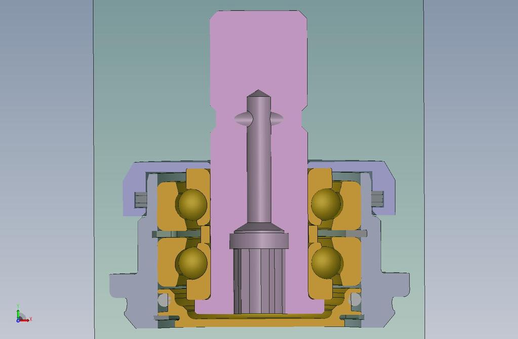
95
96
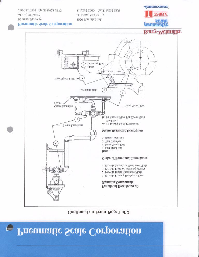
97
98
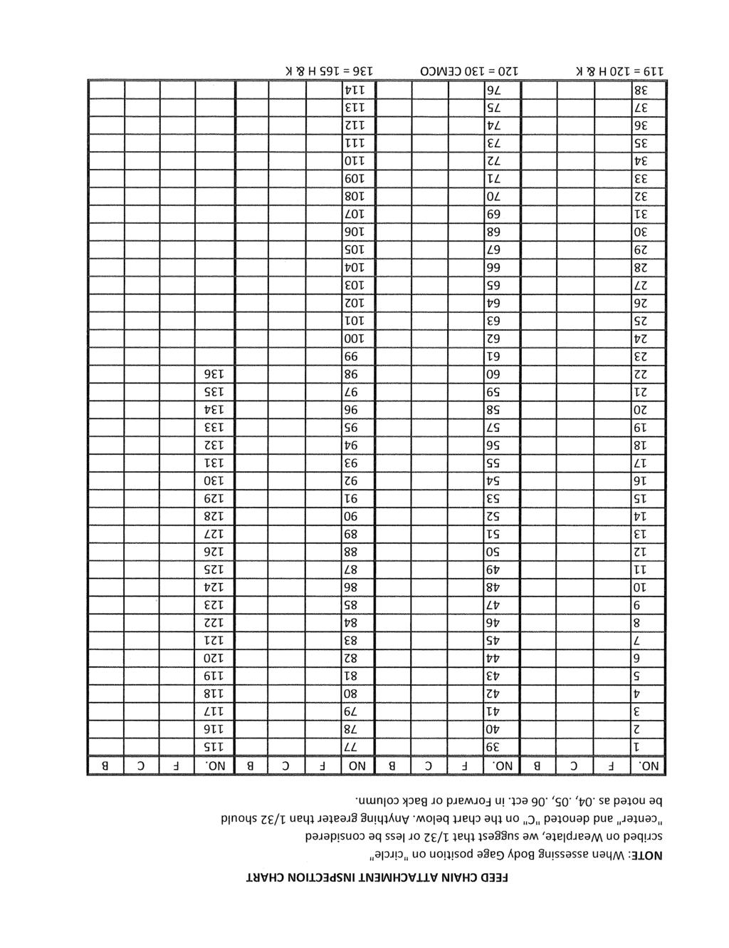
99
100 Seamer Food Grade Grease (Code P30) Food Grade Grease - NLGI 0-00 Table 7-22: Chemical/Physical Properties (Food Grade Grease) Penetration Range 60 Strokes Properties Class ASTM D Dropping Point F ASTM D Viscosity of Base Oil Pour Point, F ASTM D-97 0 Flash Point, F ASTM D Bomb Oxidation, PSI 100 hrs. ASTM D Ball Wear, 40 kg., 1200 rpm, 167 F scar diameter, mm ASTM D Water 175 F ASTM D-1264 <8% Value or Property Proprietary Description White, smooth, aluminum complex grease Table Suppliers (Lithium Base Grease) Fiske Brothers Supplier Product Name Lubriplate FGL-CCor FGL-0 LUBRICATION 2/12/
101 Bulletin: # April 3, 2003 Subject: 2006 Seaming Cam Determination Seamer Affected: 2006 Factory & Closing Machines Page: 1 of 5 REASON FOR SEAMING CAM DETERMINATION: In recent years there has been an increased need to use the new design of seaming cams to improve the ability of the seamer to handle the light weight can and end materials that the canning industry has switched over to. Unfortunately it is not always possible to find the seaming cam part number. The part number is stamped or etched into on the top surface of the cam. If however you are unable to find the part number of the Seaming Cam then this bulletin will help to positively determine if the new light weight seaming cam profile is installed on the seamer. INSTRUCTIONS: To determine the type of seaming cam that is currently on the seamer, the following procedure should be used: 1) Place calibrated tape ESG around Can Holding Chuck Table as per the illustration on page two and three of this bulletin. 2) Attach dial indicator ( M) to the Seaming Head so that the dial indictor contacts the cam follower of the 1 st operation on a line from the centerline of the cam through the centerline of the cam follower as shown in the illustration on page four of this bulletin. 3) Turn the machine by hand until the scribed line on the Can Holding Chuck Table Guard is at the 180 degreed mark. Set the dial indicator to read ) Turn machine by hand backwards to the three degreed marks listed (145, 140, 115) on the chart on page five of this bulletin. 5) Compare the indicator marks with the chart on page five of this bulletin to determine which version of seaming cam is installed on the seamer.
102 Bulletin: # April 3, 2003 Subject: 2006 Seaming Cam Determination Seamer Affected: 2006 Factory & Closing Machines Page: 2 of 5
103 Bulletin: # April 3, 2003 Subject: 2006 Seaming Cam Determination Seamer Affected: 2006 Factory & Closing Machines Page: 3 of 5
104 Bulletin: # April 3, 2003 Subject: 2006 Seaming Cam Determination Seamer Affected: 2006 Factory & Closing Machines Page: 4 of 5
105 Bulletin: # April 3, 2003 Subject: 2006 Seaming Cam Determination Seamer Affected: 2006 Factory & Closing Machines Page: 5 of 5
106 10 Ascot Parkway Cuyahoga Falls, OH USA 330/923/0491 fax 330/ Bulletin: # June 27, 2003 Subject: 2004 Seaming Cam Determination Seamer Affected: 2004 Factory & Closing Machines Page: 1 of 5 REASON FOR SEAMING CAM DETERMINATION: In recent years there has been an increased need to use the new design of seaming cams to improve the ability of the seamer to handle the light weight can and end materials that the canning industry has switched over to. Unfortunately it is not always possible to find the seaming cam part number. The part number is stamped or etched into on the top surface of the cam. If however you are unable to find the part number of the Seaming Cam then this bulletin will help to positively determine if the new lightweight seaming cam profile is installed on the seamer. INSTRUCTIONS: To determine the type of seaming cam that is currently on the seamer, the following procedure should be used: 1) Place calibrated tape ESG around Can Holding Chuck Table as per the illustration on page two and three of this bulletin. 2) Attach dial indicator ( M) to the Seaming Head so that the dial indictor contacts the cam follower of the 1 st operation on a line from the centerline of the cam through the centerline of the cam follower as shown in the illustration on page four of this bulletin. 3) Turn the machine by hand until the scribed line on the Can Holding Chuck Table Guard is at the 180 degreed mark. Set the dial indicator to read ) Turn machine by hand backwards to the three degreed marks listed (115, 111, 80, 70, 60) on the chart on page five of this bulletin. 5) Compare the indicator marks with the chart on page five of this bulletin to determine which version of seaming cam is installed on the seamer.
107 10 Ascot Parkway Cuyahoga Falls, OH USA 330/923/0491 fax 330/ Bulletin: # June 27, 2003 Subject: 2004 Seaming Cam Determination Seamer Affected: 2004 Factory & Closing Machines Page: 2 of 5
108 10 Ascot Parkway Cuyahoga Falls, OH USA 330/923/0491 fax 330/ Bulletin: # June 27, 2003 Subject: 2004 Seaming Cam Determination Seamer Affected: 2004 Factory & Closing Machines Page: 3 of 5
109 10 Ascot Parkway Cuyahoga Falls, OH USA 330/923/0491 fax 330/ Bulletin: # June 27, 2003 Subject: 2004 Seaming Cam Determination Seamer Affected: 2004 Factory & Closing Machines Page: 4 of 5
110 10 Ascot Parkway Cuyahoga Falls, OH USA 330/923/0491 fax 330/ Bulletin: # June 27, 2003 Subject: 2004 Seaming Cam Determination Seamer Affected: 2004 Factory & Closing Machines Page: 5 of 5 OLD SEAMING CAMS NEW CAMS FOR LIGHT WEIGHT MATERIALS DEG. INDICATED DIMENSION
111 10 Ascot Parkway Cuyahoga Falls, OH USA 330/923/0491 fax 330/ Bulletin: # June 27, 2003 Subject: 2004 Seaming Cam Determination Seamer Affected: 2004 Factory & Closing Machines Page: 1 of 1 REASON FOR SEAMING CAM DETERMINATION: In recent years there has been an increased need to use the new design of seaming cams to improve the ability of the seamer to handle the light weight can and end materials that the canning industry has switched over to. Unfortunately it is not always possible to find the seaming cam part number. The part number is stamped or etched into on the top surface of the cam. If however you are unable to find the part number of the Seaming Cam then this bulletin will help to positively determine if the new lightweight seaming cam profile is installed on the seamer. INSTRUCTIONS: To determine the type of seaming cam that is currently on the seamer, the following procedure should be used: 1) Place calibrated tape ESG around Can Holding Chuck Table as per the illustration on page two and three of this bulletin. 2) Attach dial indicator ( M) to the Seaming Head so that the dial indictor contacts the cam follower of the 1 st operation on a line from the centerline of the cam through the centerline of the cam follower as shown in the illustration on page four of this bulletin. 3) Turn the machine by hand until the scribed line on the Can Holding Chuck Table Guard is at the 180 degreed mark. Set the dial indicator to read ) Turn machine by hand backwards to the three degreed marks listed (115, 111, 80, 70, 60) on the chart on page five of this bulletin. 5) Compare the indicator marks with the chart on page five of this bulletin to determine which version of seaming cam is installed on the seamer.
112 10 Ascot Parkway Cuyahoga Falls, OH USA 330/923/0491 fax 330/ Bulletin: # June 27, 2003 Subject: 2004 Seaming Cam Determination Seamer Affected: 2004 Factory & Closing Machines Page: 2 of 2
113 10 Ascot Parkway Cuyahoga Falls, OH USA 330/923/0491 fax 330/ Bulletin: # June 27, 2003 Subject: 2004 Seaming Cam Determination Seamer Affected: 2004 Factory & Closing Machines Page: 3 of 3
114 10 Ascot Parkway Cuyahoga Falls, OH USA 330/923/0491 fax 330/ Bulletin: # June 27, 2003 Subject: 2004 Seaming Cam Determination Seamer Affected: 2004 Factory & Closing Machines Page: 4 of 4
115 10 Ascot Parkway Cuyahoga Falls, OH USA 330/923/0491 fax 330/ Bulletin: # June 27, 2003 Subject: 2004 Seaming Cam Determination Seamer Affected: 2004 Factory & Closing Machines Page: 5 of 5 OLD SEAMING CAMS NEW CAMS FOR LIGHT WEIGHT MATERIALS DEG. INDICATED DIMENSION
116 10 Ascot Parkway Cuyahoga Falls, OH USA Phone: (330) Fax: (330) Web Site: www. pneumaticscale.com Bulletin: # April 12, 2006 Subject: Adding an extra Bellville when using Eco-Seal Tooling Seamer Affected: Closing Machines Page: 1 of 1 REASON FOR CONVERSION When using CMB tooling with the Eco-Seal option it is recommended that an extra Belleville washer be used on the first and second operation shank assemblies. This is due to the dimension from the top of the seaming roll to the seaming roll groove increasing by approximately.031. This causes the shank assemblies to be adjusted higher to compensate for the additional height of the roll assembly. This condition then reduces the spring pressure that is necessary to hold the shanks in the correct relationship to the seaming chuck. CORRECTIVE ACTION Below is a sectional diagram showing the standard configuration for the Bellville washers: When using the Metal Box Eco-Seal seaming rolls one extra Bellville washer should be added to the bottom of the stack as shown in sectional diagram below:
117 10 Ascot Parkway Cuyahoga Falls, OH USA Phone: (330) Fax: (330) Web Site: www. pneumaticscale.com Bulletin: # August 11, 2006 Subject: Modified shanks for direct greasing of rolls. Seamer Affected: Closing Machines Page: 1 of 1 REASON FOR CONVERSION This modification is done to eliminate greasing the rolls through the seaming head grease ports. It consists of plugging the shank as shown in the drawing below and installing a zerk grease fitting for greasing the rolls at the bottom of the lever. CORRECTIVE ACTION Order the shank part numbers listed below: 1 st Operation Shank S 2 nd Operation Shank S
118 10 Ascot Parkway Cuyahoga Falls, OH USA Phone: (330) Fax: (330) Web Site: www. pneumaticscale.com Bulletin: # August 11, 2006 Subject: Modified shanks for direct greasing of rolls. Seamer Affected: Closing Machines at Miller Ft. Worth Page: 1 of 1 REASON FOR CONVERSION This modification is done to eliminate greasing the rolls through the seaming head grease ports. It consists of plugging the shank as shown in the drawing below and installing a zerk grease fitting for greasing the rolls at the bottom of the lever. CORRECTIVE ACTION Order the shank part numbers listed below: 1 st Operation Shank S 2 nd Operation Shank S
119 10 Ascot Parkway Cuyahoga Falls, OH USA Phone: (330) Fax: (330) Web Site: www. pneumaticscale.com Bulletin: # September 21, 2006 Subject: Procedure for Marking the Vertical Filler Drive Shaft Cap Seamer Affected: Closing Machines Page: 1 of 1 REASON FOR PROCEDURE The procedure outlined below will be necessary when installing the new SST vertical filler drive shaft cap. This is due to the scribed line being done on the cap at assembly for perfect alignment of the can feed turret and the seaming head. PROCEDURE The Can Feed Turret will need to be removed and then the CFT drive shaft will need to be moved back into the gassing valve bearing. The Half Mould Turret will also need to be removed. The Seaming Spindle gage will need to be installed on station one and then backed into the seamer to approximately centerline of can and end make-up. The scribe line on the CHC table will be lined up approximately in the center of the new Filler Drive Cap. A parallel bar will need to be held between the CFT drive shaft and the seaming head drive sleeve where the half mould turret mounts. A measurement with a depth micrometer will then be taken from the parallel bar to the seaming spindle gage. The parallel bar should then be moved to the opposite side of the CFT drive shaft and the seaming head drive sleeve. A measurement should be taken again from this side of the parallel bar to seaming spindle gage. The seaming head will need to be moved so that when switching the parallel bar to either side of the two shafts gives an equal measurement. At this point the seaming head is centered with the CFT. Locate the scribed line that is on the CHC table and then extend the scribed line onto the new filler drive cap.
120 10 Ascot Parkway Cuyahoga Falls, OH USA Phone: (330) Fax: (330) Web Site: www. pneumaticscale.com Bulletin: # October 23, 2006 (Rev.1) Subject: Information on the new Incline/Diverging Bubble Breakers Seamer Affected: Closing Machines Page: 1 of 4 INTRODUCTION There has been a considerable amount of confusion regarding bubble breakers and how to set them for maximum effectiveness. Also, some confusion came with the introduction of the "Creamer" and attempts to use it in place of a Bubble Breaker. This practice will compromise the potential air removal of your gassing system. In this bulletin we will review the gassing components with the focus on the Bubble Breaker. The first thing that must be considered is what are the main gassing components and how do they relate to one another. 1. BUBBLE BREAKER - A Co2 distribution Manifold with (2) vertical Orifice Plates having narrow slots to cause a pressure stream of Co2 over the filled cans coming from Filler. Depending on line speed and headspace conditions it may be beneficial to add a 2nd unit to break any remaining bubbles missed by 1st unit. 2. CREAMER - A Co2 distribution Manifold with a single, horizontal, Orifice Plate having 102 holes to flood headspace and cause a foaming effect lifting bubbles to can flange where they can be "floated" out of headspace by flow from the Top Rail Gasser and/or Nozzle Gasser. This alternative device is of benefit if "low fills" are an ongoing problem and should not be considered as a replacement for the Bubble Breaker. It is typically positioned on the Can Feed Table before the Cover Guide Plate with sufficient distance to assure that "low fill" headspace foaming will occur before can reaches the Top Rail Gassing Manifold (if used) or Nozzle Gasser. 3. TOP RAIL GASSING - A Co2 distribution Manifold insert on the bottom side of the Outer Cover Guide Extension having 91 holes in a pattern to flood the "center" of can headspace with Co2 flow causing foaming and allow bubbles to be floated out of either side of can prior to Nozzle Gassing. Key to successful use of this attachment is to carefully increase Co2 flow until some foam is pushed
121 over the can flange with care taken to minimize product loss. 4. COVER GASSING - A Co2 manifold Insert on the bottom side of the Inner Cover Guide extended over the flow zone of the Gassing Nozzles. The purpose being to provide an inert gas atmosphere in the clearance between the Inner Cover Guide and top of rotating Nozzles and reduce aspiration of air into the Nozzle Co2 stream. It is particularly effective on high-speed lines (above 1500 CPM) where elevated flow from the Nozzles causes a significant "aspiration" effect. 5. NOZZLE GASSING - The most effective approach to replacing headspace air with an inert gas just before the can and end are clamped with flow regulated to avoid excessive product loss. Below we have rated each of the gassing components in order of overall effect on "Headspace Air" removal: * NOZZLE GASSING * BUBBLE BREAKER * COVER GASSER (only on high speed lines) * TOP RAIL GASSING * CREAMER BUBBLE BREAKER TYPES Bubble breakers have evolved over the years and it is helpful to understand the different types that have been available and how to identify each type. * 1956 DESIGN - Bayonet with orifice plates having an effective slot length of 1/4" and a slot span of 3.9". * 1990 DESIGN - Bayonet with orifice plates having a reduced slot size, 1/2" slot length and a slot span of 2.8". The longer slot length permits higher pressure with sharper "knife" effect on bubbles and reduced product loss. The slot span was reduced minimizing Co2 usage since the wider span was no longer required for earlier can types up to 307 diameter. * 2006 DESIGN Incline/Diverging Wedge shaped bayonet with orifice plates having 1/2" slot length. One office plate has vertical slots and the other plate has diverging slots. BACKGROUND FOR INCLINE/DIVERGING 202 BB - With the reduced flange opening an increased possibility exists for bubbles "hiding" under the "necked in" can shoulder. The "bayonet" Manifold is made in the form of a wedge causing an "inclined" effect of the Co2 stream from the attached Orifice Plates.
122 As the can passes under the Manifold, the first or "lead" plate has vertical orifice slots and the inclined stream more effectively finds the bubbles collected under the forward can shoulder. As the can passes beneath the "trail" Plate, the inclined, diverging orifice slots "hunt" bubbles on the sides of can plus those hiding at the "trail" shoulder of can. Product loss from the "diverging" plate is reduced by mounting it as the "trail" plate or toward the seamer. The field evaluations have shown the benefits of the Incline/Diverging BB to be very promising with the results listed below: * TPO s are lowered. * Product loss is lowered and most likely will require a need to lower fill height from Filler Valves to retain "target" fills. This higher fill comes with reduced product loss from lowering Nozzle Gassing Flow and/or Rail Gassing flow if used. * Co2 usage is lowered with the effective "breaking" of bubbles and lesser need to float bubbles from headspace by higher Co2 flow from Nozzle Gassing and Rail Gassing if used. INSTALLATION - SUGGESTED GUIDELINES FOR INSTALLATION: 1. WHERE ON CAN FEED TABLE - Using a strobe, locate the point on Feed Table where the Bubbles in the Headspace seem to stabilize after the can transfer "shock". This is generally expected at a point 3' to 5' after Centerline of Can Filler and dependent on Line Speed. If a 2nd BB is used, again using a strobe, find the point on the Feed Table where remaining bubbles seem to stabilize after headspace disturbance from #1 BB. 2. HEIGHT ABOVE CAN FLANGE - The least clearance, the more effective the "knife" effect of Co2 stream. To avoid can tipping and jams resulting from a can "jumping" due to wear plate surface tension, it is suggested that minimum clearance be 1/4". Initial tests were made using 5/16" clearance. 3. ATTACHMENT OF PLATES: Depending on L.H. or R.H. mounting of the Manifold (Bayonet) it is recommended that the orifice plates be attached with the "Straight" Orifice Plate 1st contacting the headspace in the approaching can. The "Diverging " plate is mounted to have the last effect on the trailing flange of the can and is so marked to be installed on "Seamer side" of Manifold.

123 4. MOUNT THE MANIFOLD SUPPORT BRACKET so as to centralize the orifice slots over the can flange. 5. OPERATING PRESSURE - As noted when changing Bubble Breaker design from the 1/4" to 1/2" long orifice slots, the pressure can be raised on the new BB until a "visual judgment" suggests that product is being "washed" out of trailing edge of can. This is dependent on line speed and headspace disturbance. Initial tests were made at 23 lbs (gage at the manifold) and line speed of 1650 CPM using a single Bubble Breaker. On lines that are using two Bubble Breakers they are generally running 18 lbs on the #1 Bubble Breaker and 10 lbs on the #2 Bubble Breaker depending on the carbonation level of the product.
124 10 Ascot Parkway Cuyahoga Falls, OH USA Phone: (330) Fax: (330) Web Site: www. pneumaticscale.com Bulletin: # September 6, 2006 Subject: Spring and Support Spacer for Knockout Heads Seamer Affected: Closing Machines Page: 1 of 1 INTRODUCTION All beverage Closer Knockout Heads were originally equipped with a Spring and Support Spacer (P/N ) that offered an approximate 75# clamp force as the can and end were elevated to the Centerline Intake position and clamped to the rotating Lifter Wear plate. With close control of the can and end at Centerline Intake, a 75# force was found sufficient to keep the container clamped on pitch line as it is raised to the Seaming Chuck at speeds up to 2000 cpm. As line speeds increased above 2000 cpm it was found necessary to increase the clamping force up to 90# to keep the container on the pitch circle as it is raised to the Seaming Chuck. This was accomplished by designing a new Support Spacer ( ) that had the thickness increased from.125 to.268. A decision was then made to use only the.268 thick spacer with the 90# clamp force for all assemblies. With down gauging thickness of smaller diameter ends, any "off center" loading with the 90# force has been troublesome with resulting knock down flanges, curls and end creasing. Also, the smaller diameter bottom profile of the 202 can has lowered frictional clamp force and may allow the container to move off lifter wear plate pitch line. CORRECTIVE ACTION To accommodate both down gauging of end material and smaller diameter bottom profile, a new Support Spacer (P/N ) that is.187 thick is recommended. This new spacer provides approximately an 80# clamp force and will be supplied with all new and rebuilt Group Assemblies.


125 10 Ascot Parkway Cuyahoga Falls, OH USA Phone: (330) Fax: (330) Web Site: www. pneumaticscale.com Bulletin: # November 5, 2006 Subject: Information on Knockout Head Audit and Modification Seamer Affected: Closing Machines Page: 1 of 3 INTRODUCTION It is very important for lubrication to reach the knockout bushing. In order for this to be accomplished there are precision tolerances between the knockout head and the knockout bushing. If the clearances become too large then the lubrication will follow the path of least resistance causing lubrication starvation of the knockout head cam follower. Below are illustrations showing the knockout head and knockout bushing. The chart below the illustrations shows the allowable dimensions. Audit Check New Parts Field Rebuild Replace K.O. Head / Min Min. K.O. Bushing / Max Max. Max. Clearance The knockout head should also be checked to make sure that it has been updated to the latest grease passage size. A revision was made that increases the size of the grease passage from.136 to.159. This was done to reduce the grease restriction in the vertical supply route to the cam follower. The larger size holes provides a 27% increase in the

126 cross section of the grease passages and reduces the possibility of the lube to escape through the knockout head bushing clearance. The illustration below shows the increased drill passages. When auditing the knockout heads it is very important examine the condition of the keyway. The illustration below shows the knockout head and keyway.

127 When there is excessive clearance in the keyway it will allow the knockout head to twist relative to the cam path. The chart below shows the keyway specifications and the audit check for radial and axial movement of the knockout head in the bushing. Knockout Key /-.000 Knockout Head /-.000 Knockout Bushing / Indicator Position A R Audit Check Axial movement at cam follower due to head/bushing clearance. Radial movement at cam follower due to keyway looseness. Max. Expected Ind. Movement (New Parts) Suggested Overhaul Guideline

128 Bulletin: # August 12, 2008 Subject: Procedure for setting cover feed separator knives. Seamer Affected: All Closing Machines Page: 1 of 2 Introduction: Over the years, the Seaming Panel of ends has moved from a flat panel profile to a crowned panel due to end material downgaging and improvement in 1st operation wrinkle frequency and amplitude. With the crowned panel, the curl cut edge of the top end sits lower on the panel of the end below which creates a small overlap of curls and a unique situation for separation. This crowning effect causes a need to differentiate between "curl" height and optimum "separating" height. If the curl of (1) crowned panel end is measured and separator clearance is set accordingly, the separator will be shimmed to high and will cause a considerable amount of chips & shavings from the cut edge of the end being separated. These will be accumulated in the area of the cut off Fingers Operating Plate and on the Base of the Seamer below the stacks. The instructions below explain the best way to calculate "separating" height and achieve optimum shimming of Separator Knives. The "separating" height of a crowned panel end will always be less than the curl height measured on (1) end. Instructions: Hold a stack of five ends tightly together making sure they stay alighned. Take a measurement over the curls at three positions approximately 120 degrees apart as shown in the illustration below. 1
129 Record the three measurements below: Add the three measurements together and record below: Total Divide the total above by three to get the average height of the stack of five ends. Total divided by 3= (Average height of five ends) Take the average height measurement of the five ends and divide it by five to get the calculated average curl height of the individual ends. Average height of five ends 5= Average Curl Height Add to this measurement to get the maximum cover curl height setting for the cover feed screw separators. Average Curl Height +.003= Maximum Curl Height 2
130 10 Ascot Parkway Cuyahoga Falls, OH USA Phone: (330) Fax: (330) Web Site: www. pneumaticscale.com Bulletin: # March 9, 2007 Subject: Constant Radius Clinching Groove Guidelines Seamer Affected: All seamers used as Clinchers Page: 1 of 1 INTRODUCTION Below are some guidelines for choosing the correct constant radius clinching roll profile. GUIDELINES 1) End material, not body material, is considered since a good clinch setup makes no change to the can flange height or diameter. 2) End diameter is involved primarily due to the curl height and curl diameter. 3) Always consider what 1st operation Groove will be used and the entry of clinch into the first operation seaming roll groove. When choosing a clinching groove make sure that the clinching groove is sufficiently smaller (at least.008 shorter) than the first operation roll groove that you are going to be using. 4) For Vacuum/Gassing Box (TERLETT System) the.084 high is needed for 502/603 dia. to tighten clinch for vertical movement (looseness) and reduce loss of nitrogen between Gassing Box and Seamer. 5) The constant radius clinching groove should not be set any higher than over the chuck. This is necessary to prevent deep countersinks going into the first operation that could cause the end to be forced down off of the chuck as the first operation seam is formed thereby causing dead heading. Groove Groove Height End Mat l Weight End Diameter 81-DT /80 211/401 SRG /95 401/502 SRG / /603

131 10 Ascot Parkway Cuyahoga Falls, OH USA Phone: (330) Fax: (330) Web Site: www. pneumaticscale.com Bulletin: # March 12, 2007 Subject: Procedure for measuring spindles with Timken bearings. Seamer Affected: Closing Machines Page: 1 of 1 INTRODUCTION The procedure outlined below is for measuring the Timken seaming spindles. With Timken spindles it is not necessary to measure radial movement. We are more concerned with vertical endplay due the Timken bearing design. PROCEDURE An indicator should be mounted from the half mould turret as shown in the illustration below.
132 The indicator should have a flat style or slightly curved style contact tip to contact the chuck. It is too difficult to use a pointed indicator point on the small radius of the seaming chuck and it introduces the possibility of giving erroneous results. The indicator button should be centered on the edge of the chuck lip as shown. Pull chuck in downward position and set indicator to zero. Turn the seaming head back and forth a few degrees with the hand wheel and then push up on seaming chuck and record the reading in the chart below. Repeat this procedure for the remaining stations. If the vertical endplay reaches.003 then the spindles should be scheduled for a Timken bearing overhaul. Spindle 1 Spindle 2 Spindle 3 Spindle 4 Spindle 5 Spindle 6 Spindle 7 Spindle 8 Spindle 9 Spindle 10 Spindle 11 Spindle 12

133 10 Ascot Parkway Cuyahoga Falls, OH USA Phone: (330) Fax: (330) Web Site: www. pneumaticscale.com Bulletin: # May 23, 2007 Subject: Upgraded Can Feed Turret Flange Design Seamer Affected: Closing Machines Page: 1 of 2 INTRODUCTION A new can feed turret shaft has been designed that incorporates a stronger flange and clamp ring design. This has been shown to be especially beneficial when running the taller 24 & 30 oz. can sizes. This new flange can be used for running can sizes 413 and higher. This new flange and clamp ring design adds substantial strength to the can feed turret assembly and minimizes the run-out of the can feed turret. This will in turn help avoid the gulling of the can feed turret nozzles against the bottom of the cover guides. We will offer this upgraded design in two options. 1ST OPTION: The full conversion includes a new shaft with ceramic coating on the seal areas, a new flange machined to the shaft and a new clamp ring. The complete assembly is ready to install without any other machining. This option can be ordered using part number M.

134 2ND OPTION: The partial conversion includes the new flange and a new clamp ring along with an alteration print. With this option it is necessary to finish machining the flange true to the shaft as per the included alteration print. This option can be ordered using part number M.
135 10 Ascot Parkway Cuyahoga Falls, OH USA Phone: (330) Fax: (330) Web Site: www. pneumaticscale.com Bulletin: # June 5, 2007 Subject: Improved KO Rod Assembly Parts Seamer Affected: Closing Machines Page: 1 of 2 INTRODUCTION We have made some improvements to the KO rod section of the seaming spindle and KO assemblies. These changes were made to help the KO rod run truer to the knockout bearing. These changes include some new parts and also a special tool that can be used to facilitate the assembly of the KO rod bearings onto the KO rod. CORRECTION ACTION To make sure that there is no interference of the spacer to the KO rod a revision has been made to the KO rod. An undercut is machined into the KO rod as per the drawing below. All new KO rods will have this modification incorporated into them. Existing KO rods can be modified as per the drawing below.

 is being specified that is thicker with a smaller internal diameter to keep it centered and prevents it from distorting when the nut is torqued down on the")
136 We have tightened the tolerance on the KO rod spacer (Item 2) that offers a tighter internal clearance to make sure that it remains centered to the KO rod and the bearing. This new spacer part number is A new tool is available that holds the previous spacer on center during installation and tightening of the top nut. This tool is shown as item 5 and is part number If new spacers are purchased then this tool would not be necessary due to the tighter internal clearances on the new spacer. A new KO bearing top washer (Item 3) is being specified that is thicker with a smaller internal diameter to keep it centered and prevents it from distorting when the nut is torqued down on the bearing. This new washer is part number A new nut (Item 4) is also being specified that is a heavy nut with a top lock design and will be part number 35007KA. All the existing KO assemblies can be updated by ordering items 2, 3, and 4 listed below. Description Item Old Part No. New Part No. Spacer Washer Nut KA Tool 5 n/a

137 10 Ascot Parkway Cuyahoga Falls, OH USA Phone: (330) Fax: (330) Bulletin: # November 6, 2007 Subject: Improved In-Motion Timing Drive Shaft Seamer Affected: Closing Machines Page: 1 of 1 INTRODUCTION A new in-motion timing drive shaft has been designed. This new shaft incorporates hardened inserts that hold the locking dogs. In the past, some customers have added a type of hardened insert but they required unbolting the in-motion timing device and swinging it out to remove the inserts. This required a considerable amount of work and the possibility of misalignment if the surfaces of the in-motion timing device were not aligned correctly after the inserts were replaced. The new design incorporates the dogs, springs and insert into one removable unit that doesn t require removing the in-motion timing device. A new in-motion timing drive shaft is required to accept the new inserts. CORRECTIVE ACTION Remove existing shaft and replace with M which includes the inserts, mounting hardware, dogs, and springs as shown in the drawing below.
138 10 Ascot Parkway Cuyahoga Falls, OH USA Phone: (330) Fax: (330) Bulletin: # February 15, 2008 Subject: Procedure for converting to Food Grade Lube Seamer Affected: Closing Machines Page: 1 of 2 INTRODUCTION Below is the procedure for converting from Lubriplate 630-AAA to Lubriplate FGL-0 or FGL-CC. PROCEDURE 1) Remove the Spindles & KO Rods, Can Holding Chucks and Cover Feed assemblies from seamer. 2) Disassemble these components and remove old lube. Replace any bearing and seals that appear worn at this time. 3) Repack assemblies with new Lubriplate FGL-0 and set aside. 4) Open Chain Drive Gear Box and clean out excess grease. 5) Clean out lube pump reservoir and refill with Lubriplate FGL-0. 6) Remove set screw from center and right injector manifolds on the Main Base and cycle the lube pump until new lube can be seen then reinstall set screws. (If set screw is not removable then loosen bottom nut on last injector on the manifold.) 7) Remove set screw from injector manifold on the In-Motion or Static Timer manifold and cycle the lube pump until new lube can be seen then reinstall set screw. (If the set screw is not removable then loosen bottom nut on last injector on the manifold.) 8) Remove set screw from injector manifold on the Cover Feed manifolds and cycle the lube pump until new lube can be seen then reinstall set screw. (If the set screw is not removable then loosen bottom nut on last injector on the manifold.) 9) Remove set screw from injector manifold on the Top Housing manifold and cycle the lube pump until new lube can be seen then reinstall set screw. (If the set screw is not removable then loosen bottom nut on last injector on the manifold.) 10) Remove set screw from the end of the line injector manifold on the Can Holding Chuck Table and cycle the lube pump until new lube can be seen then reinstall set screw. (If the set screw is not removable then loosen bottom nut on last injector on the manifold.)
139 Bulletin: # February 15, 2008 Subject: Procedure for converting to Food Grade Lube Seamer Affected: Closing Machines Page: 2 of 2 11) Remove set screw from the end of the line injector manifold on the Seaming Head and cycle the lube pump until new lube can be seen then reinstall set screw. (If the set screw is not removable then loosen bottom nut on last injector on the manifold.) 12) Cycle grease pump until new grease can be seen in the spindle and can holding chuck bores. 13) Replace all assemblies that were removed in step 1. 14) Run seamer at half speed for one hour. 15) After one week check to make sure lube is sufficient in the Can Holding Chuck Lifter Pin. 2

140 10 Ascot Parkway Cuyahoga Falls, OH USA Phone: (330) Fax: (330) Bulletin: # June 6, 2008 Subject: Quick Change Bubble Breaker Seamer Affected: Closing Machines Page: 1 of 1 INTRODUCTION A new quick change bubble breaker has been designed that can be set up to run multiple height cans. This new quick change bubble breaker is currently configured to run two different can heights but it can be optioned to run three can heights. The initial setting of the bubble breaker requires the use of an allen wrench to set the limit stops. Once the initial can heights have been set, no tools are required to change between can heights. You simply loosen the locking handle, pull the limit stop pin out, set to the preset can height, and relock the handle. Once the bubble breaker is set there are no tools required to change between can sizes. CORRECTIVE ACTION This new bubble breaker can be ordered using part number M. It is currently designed to run can sizes between 308 to 604. It can be special ordered for taller can sizes if needed.
141 10 Ascot Parkway Cuyahoga Falls, OH USA Phone: (330) Fax: (330) Bulletin: # June 6, 2008 Subject: Cover Feed Trough Center Rod Seamer Affected: Closing Machines Page: 1 of 1 INTRODUCTION A new cover feed trough center rod has been designed for the new CDL, Super End, and LOF ends. It was discovered that these new end designs do not nest as well as the standard ends of the past did. These new ends tend to snake from one side of the trough to the other which makes it difficult to load the next sleeve of ends. The new design removes the long rod from the trough and replaces it with a very short rod (approx. 5 ). This allows the ends to stay centered in the trough since they are sitting lower in the trough. The new short rod is tapered to allow the ends to line up with the swivel. CORRECTIVE ACTION The standard 202 rods can be modified per the drawing below. It will require removing the current rod and cutting it down to five inches and then milling a taper to the end as shown on the drawing. The new short rods can also be purchased new by ordering part number

142 10 Ascot Parkway Cuyahoga Falls, OH USA Phone: (330) Fax: (330) Bulletin: # September 10, 2008 Subject: Seaming Chuck Torque Method for Timken Spindles Seamer Affected: Closing Machines Page: 1 of 1 INTRODUCTION The Timken Spindles require a standard torque setting to maintain the correct preload and endplay dimension. This torque value is 80 ft/lbs and is what is used when the spindle are built at our plant. We use a specially designed chuck that has a square hole in it to do the initial setup of spindle in our plant. We found that it is also necessary to duplicate the same torque value of the seaming chucks once the spindles are installed in the seamer. CORRECTIVE ACTION You will need to purchase a crowfoot wrench that will allow you to use a standard torque wrench with your existing chuck wrench as shown in the picture. This crowfoot wrench can be purchased from McMaster Carr using part number 5831A14 for a 1-1/8" Crowfoot wrench to be used with a ½ drive torque wrench. This crow foot wrench will have a 1-11/16 center to center distance. Taking into account the 1-11/16 offset from the crowfoot wrench the torque setting on the torque wrench should be set to 73 ft/lbs to abtain the 80 ft/lbs at the center of the seaming chuck. If a different center distance crowfoot wrench is used then a new torque value will need to be calculated to assure that the actual seaming chuck is being torqued to 80 ft/lbs.

143 10 Ascot Parkway Cuyahoga Falls, OH USA Phone: (330) Fax: (330) Bulletin: # October 22, 2008 Subject: Timken Spindle Setup Chuck Seamer Affected: Closing Machines Page: 1 of 1 INTRODUCTION The Timken Spindles require a standard torque setting to maintain the correct preload and endplay dimension. This torque value is 80 ft/lbs and is used when the Timken spindles are built at our plant. We use a specially designed setup chuck that has a square hole in it to do the initial setup and height inspection of spindle in our plant. It is also necessary to duplicate the same torque value of the seaming chucks once the spindles are installed in the seamer as per Bulletin #1044. CORRECTIVE ACTION To check the endplay and the setup height of a Timken spindle on the bench you will need to use a special setup chuck that is designed with inspection slots. This special setup chuck has a square hole in the center of it to allow a ½ inch drive torque wrench to be used with it. This chuck should be torqued to 80 ft/lbs. The slots allow an indicator needle to be inserted and the endplay and setup height can be then be checked. The setup height of the Timken spindle is / The Timken spindle setup chuck is shown below and can be ordered using part number
144 10 Ascot Parkway Cuyahoga Falls, OH USA Phone: (330) Fax: (330) Bulletin: # January 20, 2009 Subject: Retainer for Lever Height Adjustments Seamer Affected: 2003, 2004, and 2006 RCM & RDS Machines Page: 1 of 1 INTRODUCTION The adjusting nut retainer is designed to keep the height adjusting nut from turning after the proper lever height has been set. The retainer is not to be so tight that it binds the adjusting nut. There should be a small amount of play between the retainer and the adjusting nut. There have been reports that the adjusting nut retainer can become worn after many years of use allowing the lever height adjustment to change. There have also been some instances where someone finds some small play between the retainer and the adjusting nut and then machines the retainer and makes it too tight. This can lead to inconsistent seaming roll height adjustments. Your retainers should meet the dimensions shown on the drawing to assure satisfactory locking of the adjusting nut. CORRECTIVE ACTION Inspect the adjusting nut retainer p/n for wear or damage on the locking point and measure any retainers that are suspect. If the retainers do not meet the drawing tolerances shown on the drawing below then they should be replaced with new retainers. Also inspect the adjusting nuts for worn serrations and replace if necessary. Adjusting Nut Retainer

145 10 Ascot Parkway Cuyahoga Falls, OH USA Phone: (330) Fax: (330) Bulletin: # June 15, 2009 Subject: Electromagnetic Tooth Clutch Assembly with Static Timing Device Seamer Affected: 2200 UHCM Seamers Page: 1 of 1 INTRODUCTION PneumaticScaleAngelus offers a low maintenance seamer conversion to change the mechanical filler drive clutch or the air clutch drive to an electrical filler drive clutch. This single position face tooth clutch is engaged by energizing an electric armature. The electric clutch conversion offers improved performance and reliability. Additional features and benefits include: o o o o o o o o o o High starting torque with electronically set DC voltage and time interval control Adjustable holding voltage to match torque required by various models Improved performance over mechanical clutch Starting torque electronically adjustable Lower maintenance Easy filler engagement & disengagement Unit has its own standing oil reservoir Unit cannot be engaged under power thereby protecting seamer and filler gear trains Incorporates static timing device with fewer parts requiring less maintenance Innovative design for new high speed seamers This conversion can be configured to upgrade existing static timing devices or to completely convert existing dynamic timing devices.
146 10 Ascot Parkway Cuyahoga Falls, OH USA Phone: (330) Fax: (330) Bulletin: # July 13, 2009 Subject: 202 Seaming Cam Improvements Seamer Affected: 2150, 2200 UHCM Seamers Page: 1 of 1 INTRODUCTION The existing 202 Seaming Cam evolved from seaming needs established beginning in 1992 with industry agreement for the 202 SOT End, later becoming the type B64 End. More recent End developments include: o CMB Super End o A/B LOF o Ball CDL+ End material thickness has moved from.0092 to.0082 with curl variations and the corresponding changes to the 1 st and 2 nd operation thickness. Also troubling has been the loss of the seaming chuck "anvil" centering effect of the End for the new profiles. This reduces safety clearance of End curl as it passes by the 1 st operation roll groove support shelf as the Can & End rise to seat on the seaming chuck. CORRECTIVE ACTION A new seaming cam P/N has been designed that incorporates improvements needed to better run the new 202 End designs. Some of the improvements are outlined below. 1) Provided more clearance between End Curl and the 1st operation roll groove support shelf to minimize the possibility of hitting the seaming roll due to "off center" clamping which can create "knock down" curls and seam leakers. 2) Uses the current seaming spindle turns per can space (1.152 on 2150 /2200-HCM) while holding the effective 1 st operation reduction "bite" to.018 per turn. 3) Reduces effective 2nd operation reduction "bite" from.025 per turn down to.019 per turn to improve 2 nd operation seam formation and reduce 2 nd operation torsional loads. 4) Changed the 2nd operation reduction stroke to lower roll groove impact on the finished 1 st operation seam.
147 10 Ascot Parkway Cuyahoga Falls, OH USA Phone: (330) Fax: (330) Bulletin: # April 16, 2010 Subject: Seaming Spindle Length Change Seamer Affected: Closing Machines Page: 1 of 2 INTRODUCTION: All new or newly reworked Seaming Spindles, , have been shortened.040 on the Seaming Chuck mounting end of the spindle. The new overall length of the Spindle is now REASON FOR SEAMING SPINDLE LENGTH CHANGE: 202 Diameter Seaming Chucks have shortened length female threads which exposes approximately.040 of the end of the Seaming Spindle. The 4 post spanner wrench used in removing chucks damages the exposed threads. This created a situation where sometimes the Seaming Chucks have to be destroyed during removal. All other diameter Seaming Chucks do not have this issue, however, all new and reworked Spindles will be shortened regardless of Seaming Chuck diameter. CORRECTIVE ACTION: Since the Spindle has been shortened the lower KO Rod Bushing, , should be installed.040 closer to the end of the Spindle. If this is not done then the U-Cup Seal will be compressed and will not function correctly. The dimension from end of Spindle to the front edge of the Bushing is now.725 to allow the needed room for correct installation of the U-Cup Seal. INSTRUCTIONS: For shops who rebuild the Seaming Spindle Assembly, M, if an installation fixture is used to locate the bushing in the Spindle; it should be shortened by.040. Check to make sure the bushing is installed.725 from the end of the spindle as shown in the diagram on page 2.

148 Bulletin: # April 16, 2010 Subject: Seaming Spindle Length Change Seamer Affected: Closing Machines Page: 2 of 2 2

149 10 Ascot Parkway Cuyahoga Falls, OH USA Phone: (330) Fax: (330) Bulletin: # April 16, 2010 Subject: Seaming Spindle Length Change Seamer Affected: Closing Machines Page: 1 of 2 INTRODUCTION: All new or newly reworked Seaming Spindles, , have been shortened.040 on the Seaming Chuck mounting end of the spindle. The new overall length of the Spindle is now REASON FOR SEAMING SPINDLE LENGTH CHANGE: 202 Diameter Seaming Chucks have shortened length female threads which exposes approximately.040 of the end of the Seaming Spindle. The 4 post spanner wrench used in removing chucks damages the exposed threads. This created a situation where sometimes the Seaming Chucks have to be destroyed during removal. All other diameter Seaming Chucks do not have this issue, however, all new and reworked Spindles will be shortened regardless of Seaming Chuck diameter. CORRECTIVE ACTION: Since the Spindle has been shortened the lower KO Rod Bushing, , should be installed.040 closer to the end of the Spindle. If this is not done then the U-Cup Seal will be compressed and will not function correctly. The dimension from end of Spindle to the front edge of the Bushing is now.725 to allow the needed room for correct installation of the U-Cup Seal. INSTRUCTIONS: For shops who rebuild the Seaming Spindle Assembly, M, if an installation fixture is used to locate the bushing in the Spindle; it should be shortened by.040. Check to make sure the bushing is installed.725 from the end of the spindle as shown in the diagram on page 2.

150 Bulletin: # April 16, 2010 Subject: Seaming Spindle Length Change Seamer Affected: Closing Machines Page: 2 of 2 2
151 10 Ascot Parkway Cuyahoga Falls, OH USA Phone: (330) Fax: (330) Bulletin: #1050 October 5, 2010 Subject: KO Button Centralized Lube Assembly Kit Seamer Affected: 2003, 2004, & 2006 RCM & RDS Seamers Page: 1 of 1 INTRODUCTION: A new lubrication conversion kit has been developed for the 2000 series seamers that improve the lubrication of the KO Buttons and KO Cams thereby increasing the life of these components. It was determined that all of the lubrication points on the 2000 series seamers had grease fittings and most of the stationary lube points were all banked. This made it very easy to forget to grease the KO Buttons and contributed to wear on the KO Cams. The new KO Button lubrication conversion gives the operator a positive way to get grease to the KO Buttons and the KO Cams. CORRECTIVE ACTION: The new centralized lubrication conversion kit incorporates a lubrication brush into the kicker cam that coats the KO Buttons with a film of grease as shown in the drawing below. This kit includes the new kicker cam with a lubrication brush as well as the fittings and hardware to bank the lube fitting into the top housing. The new KO Button Centralized Lube assembly can be ordered using part number M

152 10 Ascot Parkway Cuyahoga Falls, OH USA Phone: (330) Fax: (330) Bulletin: #1050 October 5, 2010 Subject: KO Button Centralized Lube Assembly Kit Seamer Affected: 2003, 2004, & 2006 RCM & RDS Seamers Page: 1 of 1 INTRODUCTION: A new lubrication conversion kit has been developed for the 2000 series seamers that improve the lubrication of the KO Buttons and KO Cams thereby increasing the life of these components. It was determined that all of the lubrication points on the 2000 series seamers had grease fittings and most of the stationary lube points were all banked. This made it very easy to forget to grease the KO Buttons and contributed to wear on the KO Cams. The new KO Button lubrication conversion gives the operator a positive way to get grease to the KO Buttons and the KO Cams. CORRECTIVE ACTION: The new centralized lubrication conversion kit incorporates a lubrication brush into the kicker cam that coats the KO Buttons with a film of grease as shown in the drawing below. This kit includes the new kicker cam with a lubrication brush as well as the fittings and hardware to bank the lube fitting into the top housing. The new KO Button Centralized Lube assembly can be ordered using part number M
153 10 Ascot Parkway Cuyahoga Falls, OH USA Phone: (330) Fax: (330) Bulletin: #1051 October 5, 2010 Subject: Left Hand Steam Rail for 2000 Series Closers Seamer Affected: 2003, 2004, & 2006 RCM & HCM Seamers Page: 1 of 1 INTRODUCTION: Pneumatic Scale Angelus is offering newly designed Left Hand Steam Rails that are used on 2003, 2004 & 2006 RCM & HCM Closers. The old style Left Hand Steam Rail construction offered a screen for steam diffusion from the rail to exhaust the headspace air from the incoming product. The new style Left Hand Steam Rail assembly offers a series of (38) tapered holes to diffuse steam directly to the can flange at an elevation to offer optimum steam flow for headspace air removal. REASONS FOR CHANGE: 1) The old construction with screen is completely functional when the screen is clean. The problem is that many users find that product dries and clogs the screen creating a need to elevate the steam regulator pressures to maintain desired vacuum levels. 2) The increased steam regulator pressures affect the other two air removal parts referred to as the Top Chamber and the Inner Steam Rail. Higher steam pressure than needed at these two rails may cause product loss. 3) A third part that is affected by the increased steam pressure is the Right Hand Rail used to flush air from bottom surface of incoming Ends. Elevated steam flow on this rail may cause excessive heating of the Ends (especially the lighter base weight material) and cause associated seaming issues. The newly designed Left Hand Steam Rails have been used successfully in lowering the steam regulator pressure required and the need for continual cleaning of old style screen. This eliminates the problems associated with needing to raise the regulator pressures. This also means lower steam usage and less chance of seaming problems caused by excessive steam usage.

154 Bulletin: #1051 October 5, 2010 Subject: Left Hand Steam Rail for 2000Series Closers Seamer Affected: 2003, 2004, & 2006 RCM & HCM Seamers Page: 1 of 1 CORRECTIVE ACTION: The new Left Hand Steam Rail incorporates an insert which contains the tapered holes and can be rotated to offer the optimum elevation for steam diffusion required for standard lifter stroke or high lifter stroke cams. The design intent is for the hole elevation to be 1/3 below and 2/3 above the can flange. This elevation offers optimum head space air removal and avoids any "venturi effect" of pulling air from below the can flange and into the steam flow moving over the top of the can. The newly designed Left Hand Steam Rails are available for the applications listed below: Seamer Part No. Description 2004, M LH Steam Rail H.C. 2004, M LH Steam Rail H.C TBE LH Steam Rail H.C. 2

155 10 Ascot Parkway Cuyahoga Falls, OH USA Phone: (330) Fax: (330) Seamer Technical Bulletin Bulletin: #1052 April 15, 2011 Subject: Sealed Discharge Turret Conversion Seamer Affected: 80L/81L, 100L/101L & 120L/121L Seamers Page: 1 of 1 INTRODUCTION: A new sealed Discharge Turret Assembly conversion has been developed for the 120L & 121L seamers. It incorporates a sealed oil bath lubrication which increases the life of the internal components. It is also more hygienic due to the housing being constructed out of stainless steel as well as being sealed which keeps contaminates out of the housing. The new Discharge Turret Assembly is designed to use the existing change parts that are already on the seamer. This new Discharge Turret Assembly can be installed without removing the upper turret housing which greatly decreases the conversion time required. It utilizes a split column for increased ease of installation and improved seal replacement. CORRECTIVE ACTION: The new sealed Discharge Turret Assembly can be ordered which will include all of the new conversion parts necessary. The upper turret housing is then supported with a temporary brace which allows the old column to be cut and then removed along with the old discharge housing. The new column is then installed with the new stainless steel housing. The new gears and bushings are then installed along with the sealed hub incorporating a labyrinth seal design.
156 10 Ascot Parkway Cuyahoga Falls, OH USA Phone: (330) Fax: (330) Seamer Technical Bulletin Bulletin: #1053 October 15, 2011 Subject: Adjusting Worm & Shank Broken Teeth Seamer Affected: 2000 Series RCM, 2006 & 8 HCM, 2150 & HCM Page: 1 of 1 INTRODUCTION: The purpose of this technical bulletin is to review the seam adjusting procedure for the subject machines to avoid user concerns related to broken teeth on the Adjusting Worm & Shank. Broken teeth are often attributed to seaming load rather than the actual cause of not relieving the clamping force of the radial "split clamp" on Levers before turning the Adjusting Worm. This erroneous belief is often reinforced by knowing 2 nd operation seaming load is much higher and observing a greater number of broken teeth on 2 nd operation. Broken teeth are found on 1 st operation parts also but at a lower level because of less frequent adjustments being required. The actual cause of broken teeth stems from a maintenance practice carried forward from older seam adjusting designs using a vertical clamp rather than the "no slip" split and radial clamp system. The vertical clamp design could be forced with only minor damage to teeth if not completely loosened (snugged) but tight enough to permit moving the adjustment. The adjusted movement to the shank was thru a separate "adjusting dog" with sliding fit on the shank with teeth engaging the worm. If the vertical clamp was loosened, a "back-off" condition occurred. This situation could require as many as (3) or more trials to reach the desired setting. Hence the practice of "snugging" loose the vertical clamp was used. SUMMARY: The new design of Upper Lever/Shank "system adjustment" uses direct worm engagement of teeth on the shank. This feature, in combination with the positive radial split clamping on the lever, eliminates the "back-off condition" if the adjustment is always left in a tightening position. Changing the tightness setting always requires loosening the radial clamp before moving the adjusting worm. Broken teeth are only encountered by a partial loosening (snugging) of the radial clamp. Once the radial clamp is re-tightened, the seaming load is carried by the "clamping force" with no load transmitted to the teeth. Correct loosening and retightening of the split & radial clamp system should eliminate broken teeth on these components while still allowing for accurate seam adjustments.
157
158
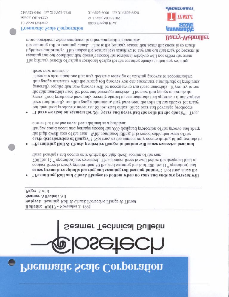
159
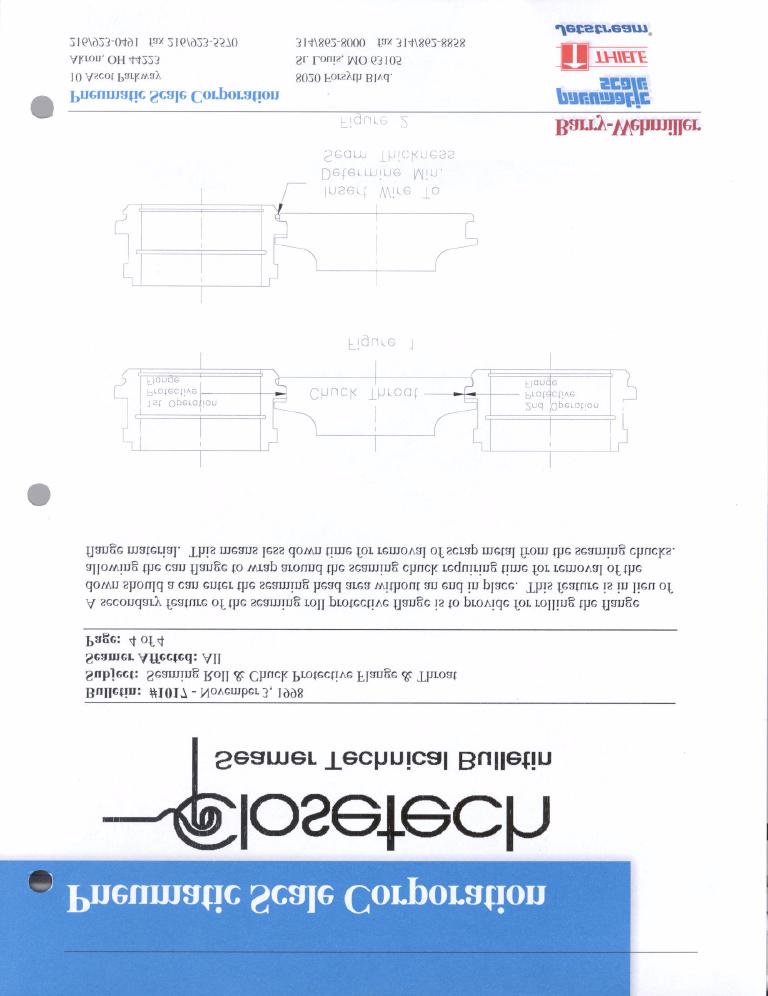
160
DIRECT DRIVE DIXIE DOUBLE SEAMER Model 25D
 OPERATOR'S MANUAL DIRECT DRIVE DIXIE DOUBLE SEAMER Model 25D LUBRICATE DAILY: A. Gears inside gear housing at chuck shaft (1) Oil B. Seam rolls and cam rolls (4) - Oil C. Seam roll levers through gear
DBML-60/80 Squeeze Tool
 DBML-60/80 Squeeze Tool OPERATORS MANUAL Description The Mustang Model DBML-60/80 Hydraulic squeeze tool has been manufactured since 1995. A Mustang 3 3/4 bore doubleacting cylinder producing 41,000 lbs
Model 23H Hand Crank Seamer
 OPERATOR'S MANUAL Model 23H Hand Crank Seamer If you are not experienced with your seamer, please read and understand this manual before operating the machine. If you have a question discuss it with your
MUELLER. Mega-Lite Drilling Machine. Reliable Connections. table of contents PAGE. Equipment 2. Operating Instructions 3-4. Parts Information 5
 operating Instructions manual MUELLER Mega-Lite Drilling Machine table of contents PAGE Equipment 2 Operating Instructions 3-4 Parts Information 5 Travel Charts 6-11! WARNING: 1. Read and follow instructions
Specifications Testing & Adjusting Disassembly & Assembly
 SB4191E00 Jul. 2005 Specifications Testing & Adjusting Supplement for Quad Lift Mast D20/25/30/32/33S-3 G/GC20/25/30/32P-3 G/GC20/25/30/32E-3 Important Safety Information Most accidents involving product
1.0 - OPENING AND CLOSING THE DOOR
 The purpose of this manual is to provide the user with instructions on how to safely open and close, how to conduct routine maintenance, and how to install the PEI TWINLOCK Closure on a pressure vessel.
Index Table. Model 794. Installation, Operating and Maintenance Instructions
 CLOCKWISE MANUAL MAKING INTO CCW TABLE Index Table Model 794 Installation, Operating and Maintenance Instructions Black & Webster Products Division 545 Hupp Ave. P.O. Box 831, Jackson, Michigan 49204 2009
APP pumps APP and APP Disassembling and assembling
 Service guide APP pumps APP 11-13 and APP 16-22 Disassembling and assembling hpp.danfoss.com Table of Contents Contents 1. Introduction... 2 2. Disassembling the pump... 3 3. Assembling the pump... 6 4.
Tex-914-K, Calibrating Motorized Gyratory-Shear Molding Asphalt Press
 Molding Asphalt Press Contents: Section 1 Overview...2 Section 2 Apparatus...3 Section 3 Procedure...4 Section 4 Adjusting Pressure Gauges...6 Section 5 Removing Air from the Hydraulic System...8 Section
OWNER S MANUAL READ THIS MANUAL BEFORE USING YOUR NEW AIRGUN
 OWNER S MANUAL READ THIS MANUAL BEFORE USING YOUR NEW AIRGUN FX SUPER SWIFT Table of Contents Warranty Specifications General Instructions Operating Instructions Trigger Adjustments Care & Maintenance
MASTER TRUING STAND TS-3. Optional Dial indicator set with brackets Dial indicator bracket set only
 MASTER TRUING STAND TS-3 3 2 1 3 8 9 4 10 7 6 5 12 13 Optional 1555-1 Dial indicator set with brackets 1556-1 Dial indicator bracket set only 49 11 16 14 15 48 32 31 37 38 20 19 17 18 34 39 21 36 22 33
Disassembling and assembling APP and APP 16-22
 MAKING MODERN LIVING POSSIBLE Instruction Disassembling and assembling APP 11-13 and APP 16-22 ro-solutions.com Table of Contents 1. Disassembling...3 2. Disassembling the pump...3 3. Assembling the pump....7
Paintball Marker. User s Manual. 530 South Springbrook Road Newberg, OR 97132
 Paintball Marker User s Manual 530 South Springbrook Road Newberg, OR 97132 Component Concepts, Inc., 530 South Springbrook Road, Newberg, OR 97132 Phone: (503) 554-8095 Fax: (503) 554-9370 www.phantomonline.com
Only. Gives You the TechLock. System Advantage ASSEMBLY, DISASSEMBLY AND TROUBLESHOOTING INSTRUCTIONS FOR 3000 SERIES FONTAINE
 April 00 Only Gives You the TechLock System Advantage ASSEMBLY, DISASSEMBLY AND TROUBLESHOOTING INSTRUCTIONS FOR 000 SERIES FONTAINE C o n n e c t y o u r b u s i n e s s w i t h F O N T A I N E April
TECHNICAL INFORMATION
 TECHNICAL INFORMATION Models No. TD0101, TD0101F Description Impact Driver L PRODUCT P 1/ 14 CONCEPT AND MAIN APPLICATIONS Models TD0101 and TD0101F are cost-competitive 100N.m-class impact driver developed
Fontaine Fifth Wheel Ultra LT Rebuild Procedures
 Fontaine Fifth Wheel Ultra LT Rebuild Procedures Disassembly Assembly Adjustments 800-874-9780 2010 LT-147 January 2010 Dissassembly Cover plate removed for clarity. Refer to exploded view of assembly
BRONZE BUSHING REPLACEMENT PROCEDURE DN345 & NL450C
 1 BRONZE BUSHING REPLACEMENT PROCEDURE V.2 12/3/2014 DN345 & NL450C 2 Safety Instructions Removing Walking Beams 3 1. Position spreader on a flat concrete surface capable of supporting weight of spreader
Welker Sampler. Model GSS-1. Installation, Operation, and Maintenance Manual
 Installation, Operation, and Maintenance Manual Welker Sampler Model GSS-1 The information in this manual has been carefully checked for accuracy and is intended to be used as a guide to operations. Correct
CLASS D - SENSITIVE LEAK TEST GAS AND BUBBLE METHOD. 1.1 To provide definitive requirements for PNEUMATIC pressure testing of piping systems.
 Page 1 of 7 CLASS D - SENSITIVE LEAK TEST GAS AND BUBBLE METHOD 1. SCOPE 1.1 To provide definitive requirements for PNEUMATIC pressure testing of piping systems. 1.2 The piping system as used herein is
P5513. Users Manual. Pneumatic Comparison Test Pump. Test Equipment Depot Washington Street Melrose, MA TestEquipmentDepot.
 Test Equipment Depot - 800.517.8431-99 Washington Street Melrose, MA 02176 TestEquipmentDepot.com P5513 Pneumatic Comparison Test Pump Users Manual PN 3963372 November 2010 2010 Fluke Corporation. All
Installation, Operation and Maintenance Manual for Back Pressure Regulator
 Installation, Operation and Maintenance Manual for Back Pressure Regulator Model 8860 2009 Groth Corporation IOM-8860 Rev. B 12541 Ref. ID: 95565 Page 2 of 13 Table of Contents I. INTRODUCTION 3 II. DESIGN
Summary of Accumulators These operating instructions apply to the accumulators listed in the table shown below.
 Page 1 of 15 Summary of Accumulators These operating instructions apply to the accumulators listed in the table shown below. Model Number A25-XXXX-3.6K Series A40-XXXX-3K Series A40X-XXXX-3.6K Series A60-XXXX-3K
Tripod Setup Guide (M-TPx)
") Items needed: 1/2 inch wrench, mast level (M-MLA), medium size wire cutters, crescent wrench, all-purpose grease, tape measure, tie wraps, redi-mix cement (optional), shovel (optional), sledge hammer (for
Items needed: 1/2 inch wrench, mast level (M-MLA), medium size wire cutters, crescent wrench, all-purpose grease, tape measure, tie wraps, redi-mix cement (optional), shovel (optional), sledge hammer (for
SERVICE BULLETIN. TOPIC: Cylinder NUMBER: SUPERSEDES: NEW DATE: May 15, Indexing Basic Cylinder Height On CFR F-1/F-2 Rating Units
 SERVICE BULLETIN TOPIC: Cylinder NUMBER: 4-013 SUPERSEDES: NEW DATE: May 15, 2004 MODELS APPLICABLE TO: TEST METHOD: ROUTE TO: F-1 Research D 2699 F-2 Motor D 2700 F-1/F-2 Combination D 2699, D 2700 F-4
MODEL 200 KNIFE GATE VALVES INSTALLATION & MAINTENANCE MANUAL
 MODEL 200 KNIFE GATE VALVES INSTALLATION & MAINTENANCE MANUAL Index 1. List of components / General arrangement 2. Description 3. Handling 4. Installation 5. Actuators / Operation 6. Maintenance a. Changing
Operation Manual Piston Sensed Gas Pressure Regulators
 687 Technology Way Napa, CA 94558 Phone: (707) 259-0102 FAX: (707) 259-0117 www.aptech-online.com Operation Manual Piston Sensed Gas Pressure Regulators (Models KT9, KT10, Welded KT10, KT12) Table of Contents:
RG1200 Service and Repair Manual
 Dive Rite RG 1200 Regulator Service and Repair Manual Page 1 Text and Photography by Pete Nawrocky Copyright ( ) 1999-2000, Lamartek, Inc., dba Dive Rite RG1200 Service and Repair Manual First Stage.........................................
Anti-flood device Model B-1
 December 4, 2009 Dry Systems 123a 1. DESCRIPTION The Anti-flood Device is required when Viking accelerators are installed on dry systems according to Viking Model E-1 Accelerator Trim Charts. In the SET
OPERATOR'S MANUAL DIRECT DRIVE DIXIE DOUBLE SEAMER Model 10D
 OPERATOR'S MANUAL DIRECT DRIVE DIXIE DOUBLE SEAMER Model 10D OIL DAILY: A. Gears inside gear housing through oil groove in gear housing at cut surface of chuck shaft. (Oil through #517 gear housing cover
Air Operated Hydraulic Pumping Systems to 50,000 psi
 High Pressure Equipment Air Operated Hydraulic Pumping Systems to 50,000 psi PS-10: 10,000 psi PS-20: 20,000 psi PS-30: 30,000 psi PS-40: 40,000 psi PS-50: 50,000 psi PS-90: 90,000 psi High Pressure air
OWNER'S MANUAL. Copyright 2003 GAMMA - All Rights Reserved
 OWNER'S MANUAL AL Issue 1 - December 2003 Copyright 2003 GAMMA - All Rights Reserved OWNER'S MANUAL TABLE OF CONTENTS PAGE 1... WARRANTY PAGE 2... ASSEMBLY INSTRUCTIONS PAGE 4... MOUNTING THE RACQUET PAGE
Copyright MAY, 2008 By Grizzly Industrial, Inc. Warning: No portion of this manual may be reproduced in any shape or form without the written
 MODEL G5791/G5792 17-PIECE 1 2" IMPACT WRENCH & RATCHET KIT INSTRUCTION MANUAL Copyright MAY, 2008 By Grizzly Industrial, Inc. Warning: No portion of this manual may be reproduced in any shape or form
Discontinued. Powers Controls. Technical Instructions Document No P25 RV Rev. 1, May, RV 201 Pressure Reducing Valves.
 Powers Controls RV 201 Pressure Reducing Valves Description Features Product Numbers Dual Pressure PRV Technical Instructions Document No. 155-049P25 RV 201-1 Single Pressure PRV The RV 201 Pressure Reducing
INSTRUCTION MANUAL CZ 630/631
 INSTRUCTION MANUAL CZ 630/631 Before handling the air rifle read this manual carefully and observe the following safety instructions. Improper and careless handling of the air rifle could result in unintentional
600 / 600FC OWNER'S MANUAL
 PROGRESSION 600 / 600FC OWNER'S MANUAL Issue 2 / Version E - Dec. 10, 1997 Copyright 1997 GAMMA Sports - All Rights Reserved PROGRESSION 600 / 600FC OWNER'S MANUAL TABLE OF CONTENTS PAGE 1... WARRANTY
Crosby style JCE Safety Valve Installation, Maintenance and Adjustment Instructions CROSBY
 CROSBY Table of contents 1. Installation 1 1.1. Drainage 1 1.2. Discharge pipework 1 1.3. Preparation for installation 1 2. Pressure adjustment 1 3. Maintenance 1 4. Dismantling 1 4.1. All valve types
OWNER'S MANUAL. Copyright 1999 ATS - All Rights Reserved
 OWNER'S MANUAL AL Issue 2 - August 19, 1999 Copyright 1999 ATS - All Rights Reserved OWNER'S MANUAL TABLE OF CONTENTS PAGE 1... WARRANTY PAGE 2... ASSEMBLY INSTRUCTIONS PAGE 4... MOUNTING THE RACQUET PAGE
MANUAL SEALLESS STEEL STRAPPING TOOL MODEL A
 OPERATION MANUAL / SPARE PARTS LIST MANUAL SEALLESS STEEL STRAPPING TOOL MODEL A337.0001 13.1912.01 13191201.en/MAS/ 10.02 INDEX PAGE 1 SAFETY INSTRUCTIONS 2 2 WARRANTY CONDITIONS AND LIABILITY 4 3 APPROPRIATE
U.S. Patent No. 7,922,246. Patents Pending
 U.S. Patent No. 7,922,246 Patents Pending 2 Table of Contents Page General Information... 3 Warnings and Cautions... 4 Tools... 6 SmartDock Parts... 6 Initial Set-Up and Adjustment... 7 Select Valve Retaining
Instruction Manual. PE-25/32/37 Tapping Machines. POLYTAPP Valves
 Instruction Manual PE-25/32/37 Tapping Machines & POLYTAPP Valves Nov 2016, Revision 2 Document Number 3000111 2 M.T. Deason Company, Inc. PO Box 101807 Birmingham, AL 35210 Phone: 205 956 2266 Fax: 205
Meter, PD Series H8-S1, S3, S5, S6, & S7 Parts List
 Meter, PD Series H8-S1, S3, S5, S6, & S7 Parts List Issue/Rev. 0.0 (1/14) Bulletin PO01010 S1 S3, S5, S6, S7 The Most Trusted Name In Measurement Inner Mechanism Page 2 PO01010 Issue/Rev. 0.0 (1/14) Item
Hydraulic Punch Drivers
 SERVICE MANUAL 7804SB / 7806SB Quick Draw 7704SB / 7706SB Quick Draw Flex Quick Draw Hydraulic Punch Drivers Serial Codes AHJ and YZ Read and understand all of the instructions and safety information in
Vickers. Flow Controls. Flow Controls FN, F(C)G, FRG. Released 6/94
G, FRG. Released 6/94") Vickers Flow Controls Flow Controls FN, F(C)G, FRG Released 6/94 685 Table of Contents FN03/06/10 Model Series Application Data...............................................................................
Vickers Flow Controls Flow Controls FN, F(C)G, FRG Released 6/94 685 Table of Contents FN03/06/10 Model Series Application Data...............................................................................
Operating & Maintenance MANUAL
 Operating & Maintenance MANUAL Thank You for purchasing the golf industry s state-of-the-art STEELCLUB Putter Angle Machine. You should find it simple to operate. Please follow the instructions in this
MUELLER GAS. No-Blo Operations Using D-5. Drilling Machine. Reliable Connections. General Information 2
 operating Instructions manual MUELLER GAS TAble of contents PAGE No-Blo Operations Using D-5 General Information 2 Installing No-Blo Service Tees, Service Stop Tees and Curb Stop Tees 3-8 Reconditioning
PNEUMATIC PRESSURE CONTROLLERS
 PNEUMATIC PRESSURE CONTROLLERS VARIABLE VOLUME PRESSURE CONTROLLER MODELS: V-1 R AND V-2R The 3D Variable Volume Pressure Controller is available for requirements of 0-1,000 psi and 0-6,000 psi in absolute
TECHNICAL DATA ANTI-FLOOD DEVICE MODEL B-1 1. DESCRIPTION
 Page 1 of 6 1. DESCRIPTION The Model B-1 Anti-flood Device is required when Viking accelerators are installed on dry systems according to Viking Model E-1 Accelerator Trim Charts. In the SET condition,
You have decided to buy an LP 10 E by STEYR SPORTWAFFEN the new dimension of match air pistols!
 Congratulations! You have decided to buy an LP 10 E by STEYR SPORTWAFFEN the new dimension of match air pistols! The world-beating air pistol with electronic trigger! The STEYR LP 10 probably is the most
TECHNICAL INFORMATION
 TECHNICAL INFORMATION Model No. Description RP2300FC, RP2301FC Router CONCEPT AND MAIN APPLICATIONS Models RP2300FC and RP2301FC are upgraded sister tools of our current plunge-type electronic router Model
RC 195 Receiver-Controller
 Document No. 129-082 RC 195 Receiver-Controller Product Description The POWERS RC 195 Receiver-Controller is a pneumatic instrument that receives one, two or three pneumatic inputs. It produces a pneumatic
Meter, PD Series, E3 S6, S7 All Parts List
 Issue/Rev. 0.0 (3/13) Meter, PD Series, E3 S6, S7 All Parts List Bulletin PO01005 32 68 29 17 68 16 14 19 15 68 20 54 22 18 24 58 23 10 59 41 31 56 55 57 47 52 25 27 34 34 26 40 67 44 39 The Most Trusted
Pressure Dump Valve Service Kit for Series 2300 Units
 Instruction Sheet Pressure Dump Valve Service Kit for Series 00 Units. Overview The Nordson pressure dump valve is used to relieve hydraulic pressure instantly in Series 00 applicator tanks when the unit
Anderson Greenwood Series 93 Positive Pressure POSRV Installation and Maintenance Instructions
 Before installation these instructions must be fully read and understood Installation and maintenance instructions for Series 93 Positive Pressure Pilot Operated Safety Relief Valves (POSRV). The intent
Operating Instructions
 Operating Instructions PRECISION AIR ENTRAINMENT METER Model: 34-3265 (CT-126A) TABLE OF CONTENTS I. GENERAL INFORMATION...1 II. RELATED USER DOCUMENTATION...2 FIGURE 1 -- AIR ENTRAINMENT METER...3 III.
G250/G250 HP Compatibility of Upgrade Kit
 Engineering Bulletin December 15, 1999 #266 G250/G250 HP Compatibility of Upgrade Kit Page 1 of 9 The SCUBAPRO G250 HP is a marked improvement on the proven G250 second stage design. So much so that issues
Replaces Lesco 300 & 500 Parts Cutting Unit
 Replaces Lesco 300 & 500 Parts 3A 11 10 10 11 17 3 1 15 2 13 1 20 1 20 1 21 2 2 22 1B 30 1A 10 14 31 25 23 24 10 4 27 23 25 26 14 24 10 13A 5 5A 4A 16 0 R&R Reels Available, Lifetime Guaranteed 1 R50271
Operating instruction for the quick-change tap holders type:
 type: HF 20 HF 30 Date of edition: 15.07.2008 Stage of alteration: 4 Please keep this for future use! Contents: 1 Application range, safety instructions and technical data... 3 1.1 Application range,
Installation Troubleshooting Maintenance Instructions Installation / Start-up
 Model ZW207 Installation Troubleshooting Maintenance Instructions Installation / Start-up NOTE: Flushing of all pipe lines is to be performed to remove all debris prior to installing valve. 1. For making
602 STRINGING MACHINE OWNER'S MANUAL
 PROGRESSION 602 STRINGING MACHINE OWNER'S MANUAL AL Issue 1- April 2000 Copyright 2000 GAMMA Sports - All Rights Reserved PROGRESSION 602 STRINGING MACHINE TABLE OF CONTENTS PAGE 1... WARRANTY PAGE 2...
INSTRUCTION GUIDE S-WORKS ROAD CARBON CRANKSET (Carbon and Alloy OSBB cups)
") INSTRUCTION GUIDE S-WORKS ROAD CARBON CRANKSET (Carbon and Alloy OSBB cups) THIS BRIEF INSTRUCTION GUIDE CONTAINS IMPORTANT INFORMATION. PLEASE READ CAREFULLY AND STORE IN A SAFE PLACE. Congratulations!
INSTRUCTION GUIDE S-WORKS ROAD CARBON CRANKSET (Carbon and Alloy OSBB cups) THIS BRIEF INSTRUCTION GUIDE CONTAINS IMPORTANT INFORMATION. PLEASE READ CAREFULLY AND STORE IN A SAFE PLACE. Congratulations!
Air Mask Low/High Pressure
 Air Mask Low/High Pressure USERS MAINTENANCE INSTRUCTIONS THIS MANUAL MUST BE CAREFULLY READ AND FOLLOWED BY ALL PERSONS WHO HAVE OR WILL HAVE THE RESPONSIBILITY FOR USING OR SERVICING THIS AIR MASK. This
DM-RARD (English) Dealer's Manual. ROAD MTB Trekking. City Touring/ Comfort Bike. Rear Derailleur DURA-ACE RD-R9100 ULTEGRA RD-R8000
 Dealer's Manual. ROAD MTB Trekking. City Touring/ Comfort Bike. Rear Derailleur DURA-ACE RD-R9100 ULTEGRA RD-R8000") (English) DM-RARD001-03 Dealer's Manual ROAD MTB Trekking City Touring/ Comfort Bike URBAN SPORT E-BIKE Rear Derailleur DURA-ACE RD-R9100 ULTEGRA RD-R8000 CONTENTS IMPORTANT NOTICE... 3 TO ENSURE SAFETY...
(English) DM-RARD001-03 Dealer's Manual ROAD MTB Trekking City Touring/ Comfort Bike URBAN SPORT E-BIKE Rear Derailleur DURA-ACE RD-R9100 ULTEGRA RD-R8000 CONTENTS IMPORTANT NOTICE... 3 TO ENSURE SAFETY...
REPAIR PART NUMBER NUMBER DESCRIPTION 0137 ELE 0136 ELE 12 VOLT SOLENOID
 PART REPAIR PART NUMBER NUMBER DESCRIPTION 0137 ELE 0136 ELE 12 VOLT SOLENOID 0203 WHL 0250 WHL WHEEL HUB 0251 WHL AXLE 0252 WHL DUST CAPS 0253 WHL TIRE - 210 SP 0204 WHL 0211 WHL TIRE & WHEEL - SP 0250
Attention: This operator s manual should be read carefully before using the air rifle. ENGLISH
 Attention: This operator s manual should be read carefully before using the air rifle. 05-2004 25 Important measures when using arms: TABLE OF CONTENTS All firearms can be dangerous; they should be used
MAINTANCE MANUAL CNC ROTARY TABLE MODEL: DMNC-5C YUASA INTERNATIONAL.
 MAINTANCE MANUAL CNC ROTARY TABLE MODEL: DMNC-5C YUASA INTERNATIONAL. INDEX DESCRIPTION PAGE (1)SPECIFICATION 2 (2)OUTSIDE DIMENSION LAYOUT 3 (3)INSPECTION REPORT 4 (4)PREPARATION FOR OPERATION 5 4-1.LUBRICATING
TBV OPERATION AND MAINTENANCE MANUAL SERIES 2800: FLANGED BALL VALVE. For technical questions, please contact the following:
 TBV OPERATION AND MAINTENANCE MANUAL SERIES 2800: FLANGED BALL VALVE For technical questions, please contact the following: Engineering Department 1537 Grafton Road Millbury, MA 01527 Phone: (508) 887-9400
Installation Instructions
 Installation Instructions Durametallic SLM-6000, SLM-6100 Self contained cartridge medium duty slurry seal Experience In Motion 1 Cartridge Installation Instructions The following instruction manual is
Hydraulic Piston Accumulators
 Ride Control Engineering Services PWCE Extendavator Paul Wever Construction Equipment Co., Inc. P.O. Box 85 401 Martin Drive Goodfield, IL 61742-0085 Phone (309) 965-2005 Fax (309) 965-2905 1-800-990-PWCE
RS(H)10,15 USER MANUAL. Read the complete manual before installing and using the regulator.
10,15 USER MANUAL. Read the complete manual before installing and using the regulator.") RS(H)10,15 USER MANUAL Read the complete manual before installing and using the regulator. WARNING INCORRECT OR IMPROPER USE OF THIS PRODUCT CAN CAUSE SERIOUS PERSONAL INJURY AND PROPERTY DAMAGE. Due to
RS(H)10,15 USER MANUAL Read the complete manual before installing and using the regulator. WARNING INCORRECT OR IMPROPER USE OF THIS PRODUCT CAN CAUSE SERIOUS PERSONAL INJURY AND PROPERTY DAMAGE. Due to
Model 7989T Steel Pipe Squeezer Sch. 40 & Sch. 80. Operations Manual
 10-12 Steel Pipe Squeezer Sch. 40 & Sch. 80 Operations Manual 1.0 Introduction This manual is issued as a basic operation manual covering the Regent Model 7989T, Pipe Squeezer and Pump as manufactured
Meter, PD Series, E3 A1, S1 and E4 S1 Prior to 2005 Parts List
 Issue/Rev. 0.0 (2/13) Meter, PD Series, E3 A1, S1 and E4 S1 Prior to 2005 Parts List Bulletin PO01001 33 Pre 1994 39 32 31 21 Pre 1994 45 18 48 44 30 78 57 46 Note: Angled housing not shown. The Most Trusted
USER S MANUAL QUESTIONS? CAUTION. Model No. FMEX Serial No. Write the serial number in the space above for reference. Serial Number Decal
 Model No. FMEX81110.0 Serial No. Write the serial number in the space above for reference. USER S MANUAL Serial Number Decal QUESTIONS? If you have questions, or if parts are damaged or missing, please
Test pumps. Pressure sources. Good reasons for proper and reliable calibration
 Test pumps Pressure is one of the most commonly measured quantities in engineering, which is why exact and reliable pressure measurement is especially important. However, the characteristics of the even
INSTRUCTION MANUAL. Slavia 630/631
 INSTRUCTION MANUAL Slavia 630/631 Before handling the air rifle read this manual carefully and observe the following safety instructions. Improper and careless handling of the air rifle could result in
OPERATOR'S MANUAL Model 23 or 24 Belt Drive Electric Seamer
 OPERATOR'S MANUAL Model 23 or 24 Belt Drive Electric Seamer Model 23-500 (shown) If you are not experienced with your seamer, please read and understand this manual before operating the machine. If you
K Page 1 of 48 Air Intake - Pg. 17
 K532-53168 Page 1 of 48 Air Intake - Pg. 17 Ref # Part Number Qty Description 24 25 041 06-S 1 Gasket, elbow 25 48 054 09 1 Elbow, air cleaner Discontinued not available at Kohler Co. 35 277116-S 1 Brace,
Copyright MAY, 2008 By Grizzly Industrial, Inc. Warning: No portion of this manual may be reproduced in any shape or form without the written
 MODEL G5789/G5790 13-PIECE 3 4" IMPACT WRENCH KIT INSTRUCTION MANUAL Copyright MAY, 2008 By Grizzly Industrial, Inc. Warning: No portion of this manual may be reproduced in any shape or form without the
TECHNICAL DATA Q = C. v P S. 2 Model G-2000 Dry valve. Page 1 of 13
 Page 1 of 13 1. Description The Viking 2 Model G-2000 Dry Valve Riser Assembly consists of a small profile, light weight, pilot operated valve that is used to separate the water supply from the dry sprinkler
TECHNICAL DATA. Pressure Regulation 531a. April 24, 2009
 April 24, 29 Pressure Regulation 531a 1. DESCRIPTION The Viking Regulating Valve is a direct-acting, single-seated, spring-loaded diaphragm valve. When installed as a pilot regulating valve on a Viking
TEST FOR STABILOMETER VALUE OF BITUMINOUS MIXTURES
 Test Procedure for TEST FOR STABILOMETER VALUE OF BITUMINOUS MIXTURES TxDOT Designation: Tex-208-F Effective Date: February 2005 1. SCOPE 1.1 Use this test method to determine the Hveem stability value
MUELLER. A Wall Type. Indicator Post. Reliable Connections. General Information 2. Technical Data/ Dimensions 3. Installation 4-5.
 Installation Instructions manual MUELLER table of contents PAGE A-20814 Wall Type General Information 2 Technical Data/ Dimensions Installation 4-5 Maintenance 6 Parts 7 Indicator Post! WARNING: 1. Read
Assembly Drawing: W-311B-A01, or as applicable Parts List: W-311B-A01-1, or as applicable Special Tools: , , &
 REDQ Regulators Model 411B Barstock Design Powreactor Dome Regulator OPERATION AND MAINTENANCE Contents Scope..............................1 Installation..........................1 General Description....................1
PNEUMATIC TENSIONER MODEL A
 OPERATION MANUAL / SPARE PARTS LIST PNEUMATIC TENSIONER MODEL A452.0001 13.4210.01 CE Declaration of conformity 13421001.en/MAS/ 05.06 We declare that the machine A452 is in conformity with the following
Front derailleur. Dealer's Manual FD-M9000 FD-M9020 FD-M9025 FD-M8000 FD-M8020 FD-M8025 FD-M612 FD-M617 FD-M618 FD-M672 FD-M677
 (English) DM-FD0003-05 Front derailleur Dealer's Manual FD-M9000 FD-M9020 FD-M9025 FD-M8000 FD-M8020 FD-M8025 FD-M612 FD-M617 FD-M618 FD-M672 FD-M677 CONTENTS IMPORTANT NOTICE... 4 TO ENSURE SAFETY...
DM-MBRD (English) Dealer's Manual. ROAD MTB Trekking. City Touring/ Comfort Bike. Rear Derailleur SLX RD-M7000 DEORE RD-M6000
 Dealer's Manual. ROAD MTB Trekking. City Touring/ Comfort Bike. Rear Derailleur SLX RD-M7000 DEORE RD-M6000") (English) DM-MBRD001-04 Dealer's Manual ROAD MTB Trekking City Touring/ Comfort Bike URBAN SPORT E-BIKE Rear Derailleur SLX RD-M7000 DEORE RD-M6000 CONTENTS IMPORTANT NOTICE... 3 TO ENSURE SAFETY... 4
(English) DM-MBRD001-04 Dealer's Manual ROAD MTB Trekking City Touring/ Comfort Bike URBAN SPORT E-BIKE Rear Derailleur SLX RD-M7000 DEORE RD-M6000 CONTENTS IMPORTANT NOTICE... 3 TO ENSURE SAFETY... 4
TECHNICAL DATA. Q = C v P S
 Page 1 of 13 1. DESCRIPTION The Viking 6 Model G-6000 Dry Valve Riser Assembly consists of a small profile, light weight, pilot operated valve that is used to separate the water supply from the dry sprinkler
Product Information News
 Product Information News MMR SECOND STAGE REGULATOR VALVE CORE MSA has changed its recommended rebuilding of the MMR Second Stage Regulator s bypass sleeve assembly during the annual inspection. Based
6146XX-X OPEN STYLE HOSE REELS
 OPERATOR S MANUAL INCLUDING: OPERATION, INSTALLATION & MAINTENANCE 6146XX-XXX OPEN STYLE HOSE REELS LOW, MEDIUM & HIGH PRESSURE (FOR AIR, WATER & PETROLEUM PRODUCTS) 6146XX-X RELEASED: 2-5-90 REVISED:
Gas Lines. Technical Manual. Sumitomo (SHI) Cryogenics of America, Inc Vultee Street Allentown, PA U.S.A.
 Cryogenics of America, Inc Vultee Street Allentown, PA U.S.A.") Gas Lines Technical Manual Sumitomo (SHI) Cryogenics of America, Inc. 1833 Vultee Street Allentown, PA 18103-4783 U.S.A. Revision F: April 2008 261320A TABLE OF CONTENTS Page DESCRIPTION...1 SPECIFICATIONS...2
Gas Lines Technical Manual Sumitomo (SHI) Cryogenics of America, Inc. 1833 Vultee Street Allentown, PA 18103-4783 U.S.A. Revision F: April 2008 261320A TABLE OF CONTENTS Page DESCRIPTION...1 SPECIFICATIONS...2
Meter, PD Series, E3 S1 and E4 S to Present Parts List
 Issue/Rev. 0.0 (2/13) Meter, PD Series, E3 S1 and E4 S1 2005 to Present Parts List Bulletin PO01002 9 35 3 39 53 55 57 56 52 54 26 32 37 25 68 48 38 The Most Trusted Name In Measurement 5 31 7 44 42 16
Attention: This operator's manual should be read carefully before using the pistol! ENGLISH
 Attention: This operator's manual should be read carefully before using the pistol! 03-2003 23 Important measures when using arms: TABLE OF CONTENTS All firearms are dangerous objects, they should be used
Model GPR Primary Pressure Regulating Valve. Instruction Manual
 Model GPR-2000 Primary Pressure Regulating Valve Instruction Manual Please read this instruction manual thoroughly before using the primary pressure regulating valve, so that you may do so correctly and
Regulators repair and maintenance. XS Compact 2nd stage. January 2014 Rev XSC /3 Ed. C /14 1
 XS Compact 2nd stage January 2014 Rev XSC /3 Ed. C /14 1 XS Compact 2nd stage WARNING! This manual is intended for use by expert technicians who have already received training in equipment repairs and
632 AccuPro Set-up & Operation
 632 AccuPro Set-up & Operation Always check: Reel & Roller bearings Bent or broken blades Make sure the reel spins freely in the frame Place the Reel Into the Machine There are three lifting options for
TECHNICAL DATA 3 MODEL G-3000 DRY VALVE RISER ASSEMBLY
 Page 1 of 13 1. DESCRIPTION The Viking 3 Model G-3000 Dry Valve Riser Assembly is equipped with a small profile, light weight, pilot operated valve that is used to separate the water supply from the dry
FLEXAIR PNEUMATIC CONTROL VALVES
 FLEXAIR PNEUMATIC CONTROL VALVES Service Information INTRODUCTION The FLEXAIR Valve is a highly versatile pressure control valve with many assembly combinations for a wide variety of control functions.
EASTERN ENERGY SERVICES PTE LTD. 60 Kaki Bukit Place #02-19 Eunos Tech Park Singapore, SG Singapore Telephone: Fax:
 2 Table Of Contents 1. Introduction 3 2. About this Manual 3 3. Contacting YZ Systems 3 4. Vessel Components 4 5. Specifications 5 6. Application 6 7. Theory of Operation 7 8. DuraSite Installation & Use
Model 130M Pneumatic Controller
 Instruction MI 017-450 May 1978 Model 130M Pneumatic Controller Installation and Operation Manual Control Unit Controller Model 130M Controller is a pneumatic, shelf-mounted instrument with a separate
Threaded Closures Installation, Operation & Maintenance
 Howard Street Bulletin TT Louisville, KY 0 USA Revised Jan 0 Phone 0--0 Fax 0--00 Threaded Closures Installation, Operation & Maintenance Caution: Operating a closure can be a hazardous activity and certain
Operating Instructions Models and Hydrostatic Test Pumps
 Operating Instructions Models 36454 and 364540 Hydrostatic Test Pumps 36454 DIMENSIONS: 24 (61cm) L x 19 (48cm) W x 19.5 (50cm) H WEIGHT: 135 lbs 61.5 kg PUMP: Twin piston: Positive displacement type Inlet