KEEYASK FISH PASSAGE IDENTIFICATION OF DESIGN CONCEPTS
|
|
|
- Andrew Ellis
- 5 years ago
- Views:
Transcription
1 KEEYASK FISH PASSAGE IDENTIFICATION OF DESIGN CONCEPTS NOVEMBER 29 TH, 2012
2 Executive Summary A Keeyask fish passage feasibility study was undertaken with the goal of developing and evaluating a suite of upstream and downstream fish passage alternatives for the proposed Keeyask Generating Station (GS), and providing a recommendation of which preferred options could be carried forward for further study, if required due to stakeholder or regulatory concerns. The initial scope of this study was to recommend a preferred fish passage design based on best available information 1. However, recent discussions with federal and provincial fisheries regulators have resulted in a decision to defer the final evaluation/selection and additional design development process until a greater understanding of fish behavior is gained through monitoring of site specific behavior, once the GS is in place. In addition, a physical provision and a commitment has been made to facilitate retrofitting a fishway at some future time, if required, through reserving land at several locations adjacent to the GS as potential sites for the installation of a fish passage facility and installing non-functional closed structures in locations where it would be difficult (i.e., inaccessible and/or technically challenging) to construct a structure after the project is in place such that these structures could be opened if required. This would provide an array of potential sites for installation of a fishway once the fish behavior information from post-project monitoring becomes available. This report provides a summary of the conceptual design of fish passage alternatives for Keeyask, undertaken as part of the original scope of the Keeyask fish passage feasibility study 1. The design concepts were developed by an interdisciplinary team of engineers and fisheries biologists lead by R2 Resource Consultants, Inc. (R2). A proven effective fish passage design for a GS of similar scale to Keeyask and for the fish species found in the Nelson River does not exist, particularly for lake sturgeon. Therefore a proven design cannot be duplicated from an existing GS, and a process for creating and evaluating new and innovative designs was required. The fish passage feasibility study was organized into three components: 1. Upstream fish collection; 2. Upstream passage; and 3. Downstream passage. Upstream fish collection is highlighted as the most important and challenging component of fish passage design in that if fish cannot find the fishway entrance, then fish passage will not be possible, regardless of the method. Upstream fish passage alternatives examined in the feasibility study were limited to methods that include some level of volitional fish movement, and do not include methods that would collect fish at locations remote from the GS. Removal of the volitional movement criteria would allow - 1 -
3 for alternative fish passage facilities/programs (e.g., collecting fish with nets, traps, angling, etc.). Design criteria for the development of conceptual alternatives of the three fish passage components are outlined for the Keeyask GS including the relative scale and location of specific features and facilities. Upstream fish passage alternatives include a formal trap and transport system, fish lock/lift, structural fishway and nature-like bypass. Examples of the key components of fish passage alternatives in use at other generating stations which may be appropriate for the Keeyask GS are included for reference. Downstream fish passage alternatives were examined and the recommended alternative was to allow unhindered fish passage through the powerhouse and spillway. This is because enhancement features built into the turbines to reduce fish injury/mortality and the absence of energy dissipation block on the spillway allow for very high survival rates for fish moving downstream
4 Contents List of Tables List of Drawings Introduction Project Data Relevant to Fish Passage Biological Criteria Fish Passage Alternatives Upstream Collection and Passage Upstream Collection Location and Configuration Alternatives Upstream Collection Configuration Upstream Collection Alternatives Definitions and Discussion Upstream Passage Alternatives Upstream Passage Alt UP-1 Trap-and-Transport from Fish Collection Facility Upstream Passage Alt UP-2 UP-1 with Fishway Challenge Section Upstream Passage Alt UP-3 Nature-Like Channel Upstream Passage Alt UP-4 Concrete Fish Ladder Upstream Passage Alt UP-5 Lift or Lock to Passage Channel Upstream Passage Alt UP-6 Lift or Lock to Passage Channel with Challenge Section of Fishway Downstream Collection and Passage Summary and Conclusions Biological Uncertainties Recommendations Phased Approach General Upstream Collection and Passage Facilities Downstream Passage References List of Tables Table 1: Nomenclature for Upstream Collection Alternatives Table 2: Nomenclature for Upstream Passage Alternatives
5 List of Drawings UPSTREAM COLLECTION ENTRANCE AND COLLECTOR LOCATIONS DWG 1 UPSTREAM COLLECTION FISH COLLECTION FACILITY DWG 2 UPSTREAM COLLECTION ALT UC 1 ENTRANCE LOCATION NO. 1 DWG 3 UPSTREAM COLLECTION ALT UC 2 ENTRANCE LOCATIONS NO. 1 & 2 DWG 4 UPSTREAM COLLECTION ALT UC 3 ENTRANCE LOCATIONS NO. 1 & 4 DWG 5 UPSTREAM COLLECTION ALT UC 4 ENTRANCE LOCATIONS NO. 1 & 5 DWG 6 UPSTREAM COLLECTION ALT UC 5 ENTRANCE LOCATIONS NO. 1 THROUGH 6 DWG 7 UPSTREAM PASSAGE ALT UP 1 TRAP & TRANSPORT FROM COLLECTOR DWG 8 UPSTREAM PASSAGE ALT UP 1 TRAP & TRANSPORT FROM COLLECTOR DWG 9 UPSTREAM PASSAGE ALT UP 2 TRAP & TRANSPORT WITH CHALLENGE DWG 10 UPSTREAM PASSAGE ALT UP 2 TRAP & TRANSPORT WITH CHALLENGE DWG 11 UPSTREAM PASSAGE ALT UP 2A TRAP & TRANSPORT, FUTURE PHASE CONFIG. DWG 12 UPSTREAM PASSAGE ALT UP 3 NATURE LIKE CHANNEL PLAN & DETAILS DWG 13 UPSTREAM PASSAGE ALT UP 4 CONCRETE FISHWAY PLAN & DETAILS DWG 14 UPSTREAM PASSAGE ALT UP 5 LIFT OR LOCK PLAN & DETAILS DWG 15 UPSTREAM PASSAGE ALT UP 6 LIFT OR LOCK WITH CHALLENGE PLAN DWG
6 1.0 Introduction The Keeyask Hydropower Limited Partnership (KHLP) is proposing to construct the 695 MW Keeyask Hydroelectric Generating Station (GS) on the Nelson River in Northern Manitoba. The project is currently being designed and developed by Manitoba Hydro (MH) in partnership with four First Nations, which form the KHLP. One consideration associated with this project is the effects to existing fish movements and the feasibility of effective developing upstream and downstream fish passage facilities at the Keeyask GS. A Keeyask fish passage feasibility study was undertaken to develop and evaluate a suite of upstream and downstream fish passage alternatives for the proposed Keeyask Generating Station (GS), and provide a recommendation of which preferred options could be carried forward for further study, if required. The initial scope of this study was to recommend a preferred fish passage design based on best available information 1. However, through recent discussions with federal and provincial fisheries regulators, a decision has been made to defer the final evaluation/selection and fish passage design development process until a greater understanding has been gained regarding fish behavior once the GS is in place. In addition, a physical provision and a commitment has been made to facilitate retrofitting a fishway at some future time, if required, through reserving land at several locations adjacent to the GS as potential sites for the installation of a fish passage facility and installing non-functional closed structures in locations where it would be difficult (i.e., inaccessible and/or technically challenging) to construct a structure after the project is in place such that these structures could be opened if required. This would provide an array of potential sites for installation of a fishway once the fish behavior information from post-project monitoring becomes available. A proven effective fish passage design for a generating station of similar scale to the Keeyask GS and for the fish species found in the Nelson River does not exist, particularly for lake sturgeon. Therefore a proven design cannot be duplicated from an existing generating station, and a process for creating and evaluating a new and innovative design is required. Manitoba Hydro retained a fish passage consulting team including R2 Resource Consultants, Inc. (R2), in association with Kozmo Inc., to investigate the feasibility of incorporating upstream and downstream fish passage facilities into the Keeyask project. The consultant team (R2 design team) is comprised of engineers and fisheries biologists who specialize in the development and design of fish passage facilities. It should be noted that the development of conceptual design of fish passage alternatives examined were limited to methods that include some level of volitional fish movement, 5
7 and do not include methods that would collect fish at locations remote from the GS. As such, the alternatives presented are similar to facilities designed for true migratory species such as salmonids which require passage in order to complete their life cycle. This type of true migratory species is not found at Keeyask. Removal of the volitional movement criteria would allow for the development of alternative fish passage facilities/programs (e.g., collecting fish with nets, traps, angling, etc.) than those developed for this study. The goals for the development of conceptual design of fish passage alternatives for Keeyask are summarized as follows: Review and summarize information necessary to develop fish passage concepts, including structural and operational parameters, fisheries information, and associated data. Define and document the methods and criteria used to develop the alternatives. Criteria were to include but not be limited to: o Biological criteria (i.e., suitability for target species); o Technical issues (i.e., constructability, compatibility with project design and construction schedules, ease of modification, ease of monitoring). Develop an inventory of suitable upstream and downstream fish passage alternatives for species known to be present in the Keeyask Project area, including lake sturgeon. These alternatives were to consider operation in an ice-affected climate, and must be compatible with regulatory requirements. 2.0 Project Data Relevant to Fish Passage The Keeyask GS will be a 695-megawatt (MW) hydroelectric generating project at Gull Rapids on the lower Nelson River, 31 km west of Gillam, Manitoba. Principal project structures consist of a powerhouse complex, spillway, dams and dykes (see DWG 1). The powerhouse, including a control building and service bay, will house the equipment required to produce electricity. The spillway, dams, and dykes are required to manage the water flows essential to producing hydroelectricity. A reservoir will be created upstream of the principal structures. Permanent infrastructure consists of roads, borrow sources, and boat docking and launching facilities. Additional project information pertaining to hydrology and hydraulics and the planned operation of Keeyask is available in other memos and the Keeyask EIS ( The Keeyask Project powerhouse will contain seven vertical shaft turbines and generators, each with an intake, scroll case, and draft tube. The intake for each turbine 6
8 unit will have three openings, each with a service gate. Intake channels and tailrace channels to direct flow into and away from the powerhouse will be excavated through overburden and bedrock. The powerhouse will be located within and adjacent to the north channel of the Nelson River at the site location. Three earthfill dams (the north dam, central dam, and south dam) will be constructed across Gull Rapids, creating a reservoir upstream of the powerhouse. The dams will be zoned earth fill embankments consisting of an impervious core with granular and crushed rock filters and outer rock shells. The north dam will have a maximum height of approximately 25 m and will be approximately 100 m in length. To the north, it will connect with the north dyke and to the south with the powerhouse. The central dam will have a maximum height of approximately 28 m and will be approximately 1,600 m in length. It will extend from the powerhouse to the spillway. The spillway will be located within the channel of Gull Rapids, approximately 1.6 km south of the powerhouse (see DWG 1). The spillway will be a seven-bay concrete overflow structure with individually-controlled gates. The south dam will have a maximum height of approximately 22 m and will be 565 m in length. It will be constructed across the south channel of the river, extending from the spillway to the south dyke. A series of discontinuous earthfill dykes will be located along both sides of the river to contain water in the reservoir and limit the extent of flooding. To facilitate inspection and maintenance, a roadway will be constructed on top of the dykes and on high ground between the sections of dykes. Including the roadway sections, these earth dykes will be 11.6 km on the north and 11.2 km on the south side of the river. The reservoir will extend approximately 42 km from the generating station to the outlet of Clark Lake. Initially, the reservoir area will be 93 km 2, consisting of approximately 48 km 2 of existing waterways and approximately 45 km 2 of newly inundated lands. The reservoir area will increase over time due to the erosion of some mineral shorelines and peatland disintegration for example, by approximately 7 to 8 km 2 during the first 30 years after the Project is constructed. Several aquatic resource enhancements are under consideration to reduce potential impacts of the Keeyask GS. These measures are still under development but if implemented the design and location of these measures could affect the efficacy of fish passage alternatives. Existing sturgeon spawning habitats in the Gull Rapids area will not be available following construction of the Keeyask GS. One measure being developed to compensate for this effect is the construction of a spawning shoal near the north bank downstream of the GS. 7
9 Adult sturgeon attracted to the spawning shoal may be inadvertently attracted to the entrance of any fish collector located in the vicinity. Depending on the type of collection and passage component, attracting gravid sturgeon from the spawning shoal into the fish passage system could be detrimental to the sturgeon population. Any fish passage facility operating in this location would need to be designed to minimize the risk of transporting adult sturgeon that would otherwise use the constructed spawning shoal using techniques such as grating to preclude large sturgeon or temporary closure of facilities during the spawning season. Aquatic habitat enhancements may be developed for the south side of the channel immediately downstream of the South Dam. Depending on the type of enhancement developed, there may be potential to incorporate these measures with fish passage facilities. 3.0 Biological Criteria The development of fish passage alternatives requires consideration of structural, hydraulic, operational, and biological factors. In a broad sense, biological information will define the overall success of any selected fish passage alternative. In a detailed sense, biological criteria are needed to guide the type, location and design of fish passage components. Based on monitoring studies completed to date the fish species present at the Keeyask site do not appear to be undertaking movement behaviors typical of migratory species, as a requirement of their life history. Fish can move up and down over the GS site, but movements appear to be more for foraging movements rather than activities such as spawning. However, it it recognized that there is some uncertainty in these results. Biological criteria to guide the design of passage facilities for non-anadromous fish and species present at the Keeyask Project are still considered experimental, or early in development, as compared to criteria for anadromous fish passage facilities. Given this uncertainty, defining concepts for fish passage alternatives for fish in the Keeyask area required assumptions regarding the species, life stages, and size classes targeted for passage. Fish passage components were also identified and evaluated for the opportunity to collect biological information to refine fish passage objectives and design features in subsequent stages of fish passage implementation. The introduction of this phased developmental approach to allow testing of concepts and collection of behavior and performance data has proven to be successful for anadromous salmonid species, and is important to examine and consider with the development of fish passage facilities for the Keeyask Project. For the purposes of this report, the potential biological risks or biological benefits of providing fish passage were not evaluated. Focus was placed on biological information 8
10 such as fish species, movement periodicity, fish size and abundance and swimming abilities that are pertinent to the type, location, design and potential success of fishway components. The timing or periodicty of fish movements is of particular importance and may affect the design, size, period of operation, and likelihood of success of fish passage alternatives. Fish may exhibit directed movements to spawning habitats, or when foraging, dispersing, or seeking refugia. The timing of fish movements can affect the evaluation of fish passage alternatives, especially if passage is incorporated into water control structures. For instance, the entrance of a potential upstream fish passage facility at the Keeyask GS must consider the timing and frequency of spill (south bank) or peaking operations (north bank). Additionally, the winter ice cover on the river in the Keeyask Project Area must be considered. 4.0 Fish Passage Alternatives As noted previously, fish passage design has been organized into the following three components: Upstream fish collection; Upstream passage; and Downstream passage. This section describes the various upstream and downstream fish passage concepts that could potentially be used in conjunction with collection locations developed for Keeyask. 4.1 Upstream Collection and Passage Two primary characteristics of upstream fish passage systems were identified for considerations at Keeyask: 1) upstream collection, and 2) upstream passage. These components are described as follows: Upstream Collection defines the ability to attract and collect fish from the Nelson River downstream of the dam. This characteristic includes the ability to behaviorally or hydraulically attract or guide the fish from the river into a fish collection chamber. Typical features of an upstream collection feature include a fishway entrance (weir, orifice, slot, etc.), attraction flow to draw fish into the entrance, and a collection pool that encourages fish to stay, or traps fish in the facility to prepare for transport past the dam. Upstream Passage defines the means to move fish from the collection pool to a release site upstream of the dam. Typical features of the upstream passage feature 9
11 include various styles of fish ladders, fish lifts, fish locks, or trap and transport programs. The Upstream Collection component is typically the most challenging feature to locate and design such that it would reliably draw fish from the river into the collection pool. This is because the collection component must accommodate all of the target species and interact well with the Generating Station design details, river hydrology, site hydraulics, and planned GS operations. The ability to design the entrance component for the desired collection performance typically varies more among hydroelectric facilities than any other fishway feature. As a result, fishway entrances are often modified after their initial construction to help improve their attraction performance. One advantage for designing a system at Keeyask is the fact that the facility has not yet been constructed; there are more opportunities, and it may be less expensive to accommodate plans for fish facilities in the original construction than would likely be possible with a retrofitted system. However, a disadvantage is that there is currently no near-field fish behavior data or hydraulic data that would help confirm the normal hypothesis on how fish may approach the generating station so there is a risk that fish collection facilities may not be constructed at the optimal location. Fish movements based on foraging may have very different behavioral cues than those associated with activities such as spawning. The development of a number of potential collection locations provides opportunities to deal with this uncertainty. All potential sites would then be available for selection once the near-field information from post-project monitoring becomes available. For those locations where a closed collection facility would be installed the best available data on fish behavior will be used to optimize the location, as discussed below Upstream Collection Location and Configuration Alternatives Given the uncertainties noted above, upstream collection alternatives were developed based on two primary assumptions: Location: upstream fish passage system entrances would be located to best collect fish that are motivated to move upstream, and Configuration: entrances would be configured to best attract all of the target fish species based on current understandings of fish behavior. Six (6) upstream collection locations were identified for further consideration in this study, designated as Upstream Collection (UC) Entrance Locations #1-6, as shown on Drawing 1. Descriptions of these locations are provided below, including pertinent discussions on their merits and potential concerns. One goal of this final list of 10
12 alternatives was to represent a full suite of alternative entrance locations along the dam that are all likely to attract fish. The locations described are not meant to be precise but can be selected more precisely based on further examination which may include: additional bathymetric surveys, hydraulic modeling, or fish behavior data. Entrance locations 1 through 4 are in places that may be more inaccessible and challenging to retrofit after the GS is constructed and these are being considered for installation prior to construction. Entrance locations 5 and 6 would be feasible for retrofit after GS construction UC Entrance Location #1 North Bank of Tailrace Downstream Site of Powerhouse This location, on the north bank of the tailrace, approximately 250 meters downstream of the powerhouse (see DWG 1), was selected because the plan is to operate Units 1 and 2 all the time during the sturgeon spawning season to create suitable hydraulic conditions over the spawning shoal. Advantages of this location include: This location is believed to be far enough downstream that the velocities from the Units 1 and 2 would have an opportunity to dissipate prior to reaching this point, such that sturgeon would be able to reach this entrance during low to high generation. An entrance in this location provides ready access to the north bank shore area in an otherwise uncongested area to facilitate phasing expansion of facilities to any of the passage alternatives described below. A deep entrance is envisioned here for sturgeon, with an attraction flow trajectory and hydraulic design of the transition between the entrance and the edge of the tailrace that would provide the best hydraulic signature for sturgeon to find. The entrance can be shielded somewhat by the bankline of the tailrace so it is not overwhelmed hydraulically by turbulence in the flow from the turbines. Issues to be addressed with this entrance location include: This location could attract fish off the spawning grounds that are not intending to move upstream. Means to address this concern include the possibility of placing a grate over the entrance during spawning season to preclude large spawning sturgeon from entering. The entrance could also be closed during spawning season, and passage could be discontinued during this time or other entrance(s) could remain open if more than one entrance is incorporated. Fish moving upstream that are not near the north bank of the tailrace would likely move up to the powerhouse and pass this location. It is understood that a spawning area is to be constructed within or adjacent to the powerhouse tailrace. The development of this feature in relation to a collection site location would need further assessment to confirm effectiveness. The 11
13 collector entrance would be at the depth of the tailrace; and coordination between this entrance location and the spawning area should be considered during future design phases UC Entrance Location #2 North Bank of Tailrace, Adjacent to Powerhouse This location is similar to Location #1, but located along the north edge of the tailrace immediately downstream of Unit 1 (see DWG 1). This represents the furthest location a fish moving upstream could reach prior to finding the powerhouse and draft tube exits. Fishway entrances in similar corner locations typically work well to attract fish if draft tube discharge velocities and levels of turbulence are within the allowable swimming capabilities of the target species. Advantages of this location include: Operation of Units 2 and 3 as the first-on units (assuming they created the desired conditions in the spawning area as well or better than operating Unit 1 does), could facilitate hydraulic conditions that would allow fish to find this entrance, as they may be likely to travel up the shear zone area between the edge of the Unit 2 discharge flow and the north bank of the tailrace. Fish that bypass entrances further downstream may search along the downstream face of the powerhouse, such that they find a corner entrance. Issues to be addressed with this entrance location include: This might not be an ideal location by itself if Unit 1 is going to consistently be the first-on unit, because fish may not be able to find or reach it in the high velocity flow along the north side of the tailrace. The velocity and turbulence immediately downstream of operating units could effectively block fish that are near the center of the tailrace from accessing the north bank and this entrance location UC Entrance Location #3 South Bank of Tailrace (on the Transmission Spur) Downstream of Powerhouse This is similar to UC Entrance Location #1, but on the south side of the tailrace (on the transmission spur) approximately 250 metres downstream of the powerhouse (see DWG 1). This alternative would have similar performance characteristics to UC Entrance Location #1, and may attract fish better when Units 5, 6, and 7 are operating to create attraction flow. Advantages of this location include: 12
14 This location would help to collect fish approaching from the south side of the tailrace channel, and would help to avoid the potential to draw fish from the spawning area on the north shore. This location appears to be a good entrance location when all seven units are running, as there will be a hydraulic shear zone along the flow peeling off the end of the transmission spur which may be the furthest upstream that a fish traveling up from the south side can easily swim during full flow powerhouse conditions. The following issue would need further consideration: The site at this location is more constrained, and not all fish passage options would be feasible here (specifically the nature-like fishway alternative, due to space limitations). Technical concerns regarding personnel safety and access near the transmission features would need to be addressed UC Entrance Location #4 South Bank of Tailrace, Adjacent to Powerhouse This is similar to UC Location #2, on south bank of the tailrace but in the corner between the south end of the powerhouse face, and the south bank of the tailrace (see DWG 1). Advantages of this location are similar to UC Entrance Location #2, but biased towards south powerhouse unit operation. The following issue would need further consideration, in addition to the issues noted for UC Entrance Location #1: Similar to UC Entrance Location #3, the site area is more limited, and would not accommodate a nature-like fishway. It also would need to address safety and access needs of the transmission features UC Entrance Location #5 At Spillway on South Side of Discharge Channel This location is on the south side of the spillway discharge channel, located near the face of the spillway (see DWG 1). This location could provide for collection of fish that may be attracted to the area during periods of low to mid spill flows, especially if the open spill gate(s) were limited to the south side spill bays. Advantages of this location include: It might be possible at this location to incorporate some of the functions of the entrance into other mitigation features in the vicinity of the spillway. An alternate entrance downstream of the location shown on Drawing 1 would be feasible, which could help to attract fish at a wider range of spill flows. 13
15 Site access is good to provide any fish passage system. Issues to be addressed with this entrance location include: A water supply pumped from the tailrace would be some distance away, such as at the opposite side of the spillway, to locate the pump station in an area with good sweeping flows for debris management. High velocity from the spill flow extends a considerable distance downstream and may make it difficult for fish to find these locations during spill periods. The majority of the flow would typically be near the powerhouse, which would also be operated with a minimum flow. Flow near the spillway would be intermittent, so there would be less attraction overall to the spillway area UC Entrance Location #6 On South Bank Where Spill Flow Enters Stephens Lake The goal of this entrance is to take advantage of the high-velocity spill flow along the south shore beyond the downstream edge of the spillway (see DWG 1), where the flow enters Stephens Lake. There may be a natural weir-like standing wave in this area along the outer bank, and fish may be attracted to this higher energy flow. Advantages of this location include: It might be possible at this location to incorporate some of the functions of the entrance into other mitigation features in the vicinity of the spillway. This entrance may attract more fish than an entrance located near the upstream end of the spillway at high flows. Site access allows coupling with any of the upstream passage alternatives. Issues to be addressed with this entrance location include: There is no clear precise location where fish are blocked and the location would change with different spill operations. Not being located where fish are blocked would allow fish to pass by the location and continue some distance upstream. A water supply pumped from the tailrace would be some distance away, to locate the pump station in an area with good sweeping flows for debris management Upstream Collection Configuration In addition to the entrance location, the configuration of the entrance is a key feature to attracting and retaining fish. Fishway entrance configurations are defined by an entrance 14
16 that fish are both physically able and behaviorally motivated to swim into. Key parameters of a fishway entrance include: A sufficient attraction flow, that fish can sense as they swim upstream, Flow introduced at a depth that fish would likely swim past for entrance discovery, and An appropriate shape and size such that fish are comfortable entering, to propagate the entrance flow jet into the river, and provide a favorable velocity to attract the desired species. Sturgeon are thought to favor a deep orifice type entrance, located in the areas of higher flow. Other species may be more successfully attracted with a vertical slot type entrance, or with a combination orifice/surface weir style entrance. The new construction of the Keeyask project requires anticipation of varying entrance performances for the different species and varying project flow and operating conditions. An approach that provides an adjustable entrance was identified that could be easily modified with respect to both attraction flow amount, and entrance shape. The Upstream Fish Collection Facility illustrated on Drawing 2 provides a schematic layout of an adjustable fishway entrance facility that would be feasible at all six entrance locations describe above. It is simply a concrete box sheltered in the bankline extending from the channel floor to above the bankline with a blockout towards the river into which a variety of slots, orifices, and weirs can be installed. It has a pumped water supply to provide flow. This entrance facility would be paired with various entrance locations to create full upstream collection systems, described in the proceeding section. Features identified for the adjustable entrance Fish Collection Facility (Drawing 2) could include: A base entrance structure, sized to consider the full range of attraction flows that can accommodate the following features. An orientation of the structure that would best introduce the attraction flow into the receiving channel or river section. The orientation shown on Drawings 2 and 8 would help to propagate the attraction flow into the tailrace channel, and create a hydraulic signature that would better attract fish. A wide blockout in the structure with guide slots to hold an adjustable entrance panel. The adjustable entrance panel which could be configured for an orifice, weir, slot, or combination of these entrance shapes. 15
17 A closure gate to allow removal and modification of the entrance panel, and to allow dewatering and access to the chamber for manual collection of fish and inspections/maintenance. A hoist system that would allow removal and modifications to the entrance panel. A water supply that can provide sufficient attraction flow to the entrance to test a wide variety of entrance shapes and flows. A fish collection chamber that is large enough to accommodate the attraction flow, to be introduced through wall diffusers. A means to collect fish from the chamber, or to connect this entrance to a variety of fish passage systems, which are described in the next section. The adjustable entrance panel could be fabricated from a steel frame assembly, with removable skin panels that could accommodate a wide variety of shapes and orifice elevations. The actual features of a collection facility at Keeyask could be fine-tuned based on the preference for either a manual, more labor intensive facility, a fully automated facility, or something in-between. Each approach should be accompanied with specific fish handling protocols that would assure fish safety and health. The water supply that provides the attraction flow is a key feature, and its capacity would need to be considered in advance. Given the scale of the tailrace and river channel downstream of the dam, a water supply capacity for each entrance of 5 to 25 m 3 /s is initially envisioned for the feasibility analysis, which is similar in scale to the entrances proven to collect white sturgeon on the Columbia River in the United States. If fish passage facilities are phased, an objective of the initial phases would be to define water supply capacities more precisely for any primary and additional entrances in later phases. The attraction water source could be provided from a pump station, dedicated turbine, or turbine pump integrated into the generating station. For costing purposes, it was assumed for concept development that a new pump station would be constructed along the tailrace channel, where high sweeping velocities would help keep pump intake screens clean from debris. The water supply source and location should be investigated further as the study progresses, and could be integrated into the Fish Collection Facility water supply noted on Drawing 2. This attraction water would be introduced through wall diffusers into a collection chamber, and would be called the Auxiliary Water Supply, or AWS system. Diffusers would be sized to limit the maximum velocity through the diffuser panel at 0.3 m/s or as further defined by early phases. Diffuser sumps would need to be sized large enough to avoid turbulence and surging at the diffuser panels. 16
18 An initial configuration utilizing a deep orifice, with its bottom flush with the bottom of the tailrace channel is shown on Drawing 2. The initial orifice size of 3 metres high by 2 metres wide would provide an entrance velocity of 1.67 m/s, with an attraction flow of 10 m 3 /s. This is simply for illustration purposes, and additional discussion is warranted on the initial configuration and flow amount to attract sturgeon from the tailrace at specific locations. In addition to the fish collection chamber, a relatively simple but complete fish collection and trap system that would allow capture and collection of these fish is illustrated on Drawing 2, with a definition of where the Trap Facility starts for this analysis. This system is described in the Upstream Fish Passage alternatives section Upstream Collection Alternatives Definitions and Discussion Five upstream collection alternatives were developed, by pairing the Entrance Chamber with a variety of individual or combinations of fishway entrance locations thought to be beneficial for analysis in this study. Table 1 summarizes these pairings, which are designated as UC-1 through UC-5, meaning Upstream Collection Alternatives #1 through #5. Table 1: Nomenclature for Upstream Collection Alternatives. Alternative Label Entrance Location # Reference Drawing # Alternative Description UC-1 #1 only Dwg #3 Entrance left bank 250 m below powerhouse UC-2 #1, #2 Dwg #4 Entrances left bank 250 m below powerhouse and at powerhouse UC-3 #1, #4 Dwg #5 Entrances left bank 250 m below powerhouse and right bank of powerhouse UC-4 #1, #5 Dwg #6 Entrances left bank at powerhouse and upstream end of spillway UC-5 #1 through #6 Dwg #7 Two entrances left bank, two right bank of powerhouse, two at spillway 4.2 Upstream Passage Alternatives For this report, Upstream Passage alternatives are defined as beginning at the Fish Collection Facility, and leading to a fish release site upstream of the dam. A clear defining line between the Upstream Collection and Upstream Passage facilities is provided on Drawings 2, 8 and 9. Similar to the process followed to identify the most promising Upstream Collection systems, five Upstream Passage (UP) alternatives were identified in meetings/workshops for additional development by the R2 design team. 17
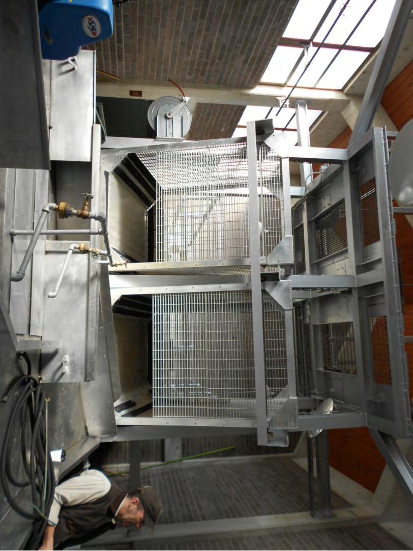
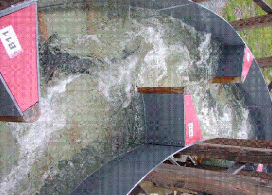
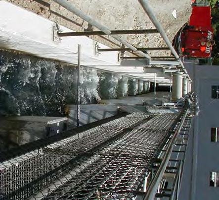
19 Table 2 provides a summary of these five Upstream Passage alternatives, which are described below and illustrated on Drawings 8 through 16. Table 2: Nomenclature for Upstream Passage Alternatives. Alternative Label Reference Drawing(s) Alternative Description UP-1 Dwgs #8, 9 Trap-and-Transport UP-2 Dwgs #10-12 UP1 (Trap and Transport) with Challenge UP-3 Dwg #13 Nature-Like Channel UP-4 Dwg #14 Concrete Fishway UP-5 Dwg #15 Lift or Lock UP-6 Dwg #16 UP5 (Lift or Lock) with Challenge All of these Upstream Passage alternatives are shown on the drawings paired with the Upstream Collection Facility located at Entrance Location #1, to illustrate how an entire collection and passage system could be developed for this one location. Working from this single entrance location also provides a common approach to developing the cost estimates for the various upstream passage alternatives. It would be feasible to combine each of the Upstream Passage alternatives with any Upstream Collection alternative, meaning any of the Passage alternatives should work with the Collection alternatives. The one exception to this observation is the Nature-Like Channel (UP Alt #3) that would not work with the Entrance Locations #3, 4, and 5. The Nature-Like Channel alternative would not be amenable to those entrance locations in the Central Dam (between the powerhouse and the spillways), as there is generally not sufficient room to build the channel in these locations (without a conveyance tunnel through the powerhouse or spillway facilities). All of these Upstream Passage alternatives are amenable to a phased approach that would allow construction of an initial Fish Collection Facility (for example Alt UP-1), which would provide for initial fish sampling and fish transport facilities, and accommodate future expansion or modification as more fish collection data became available for this specific site Upstream Passage Alt UP-1 Trap-and-Transport from Fish Collection Facility Alternative UP-1 shown on Drawings 8 and 9 illustrates a schematic layout for a Trapand-Transport facility, coupled with the Fish Collection Facility described on Drawing 2. The goals of this facility include: 18
20 Allow reliable collection of fish, while the Fish Collection Facility continues to operate and collect fish. Accommodate all of the design species, with an initial bias towards lake sturgeon. It may also be desirable for the facility to trap fish, so that once they enter the trap it is difficult for them to get back out. Devices such as a finger weir or a V-trap are common features included in traps for migratory Pacific salmon; however, given the uncertain motivation for sturgeon to move upstream, it was judged to be more desirable to allow a volitional exit from the trap to accommodate fish that may enter the trap but ultimately decide to move out and go back downstream. Accommodations to retrofit such trap devices can be provided in case future research indicates they may be useful for some species. Provide a relatively low-tech means to sample, tag and observe the fish that enter the trap, in order to collect biological data (such as species composition, fish size, fish sex, fish condition, scale or other bio-samples, run timing, time of entry to the trap, etc.). Lift the fish from the deep collection pools designed to collect sturgeon from the bottom of the tailrace, to a safe location for sampling and transport to desired locations. Hold fish to observe their condition after sampling Safely and efficiently transport fish upstream (or to other desired locations) using a Fish Truck transport system. Return fish to the tailrace if desired, through a fish return pipe. Provide design and space flexibility for future modifications and facility expansion based on fish study data. The trap-and-transport facilities illustrated on Drawings 8 and 9 are described below, in the order that fish would flow through the system. Photographs shown on Drawing 8 provide examples of working facilities for some of these key features. As noted above, this is intended to be a schematic design that identifies and describes all components, and provides a reasonable sense of scale. Additional design development will be required to refine exact trap features, dimensions, details, alignment and integration into the project site, etc. moving forward if this design is to be implemented. After entering the Collection Chamber, fish would swim through an entrance to an Intermediate Pool. The Intermediate Pool provides a means to separate the collection chamber from the trap, which is a mechanism to allow continued collection of fish in the Collection Chamber and continuous operation of the trap. In future design phases, additional Intermediate Pools should be considered to facilitate steps to accommodate facility expansion. Additionally, this Intermediate Pool would function as an entry challenge section of the trap entrance that motivated fish must enter to move into the 19
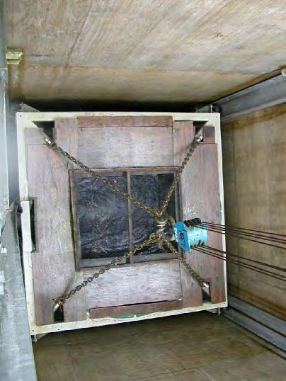
21 trap. The challenge terminology is intended to communicate a means to determine if fish are truly motivated to move upstream. The Intermediate Pool would have a bulkhead wall, with an entrance configuration determined to be the best for the target species. Drawing 9 illustrates an orifice configuration with a closure gate that would allow dewatering the pools on either side of the bulkhead, and personnel access to inspect and if necessary manually lift fish from either pool. Following the Intermediate Pool(s), fish would pass through another orifice (or other entrance shape), and enter the Trap Pool. The orifice leading into the trap pool would be fitted with picket gate fabricated of exclusionary bars or screen material to prevent the smallest design fish from exiting the chamber, but still allow flow into the pool below. The Trap Pool would contain a fish lift, designed to lift fish trapped in this pool to the surface for sampling, and transport. Considering that the trap pool would need to be about 10 metres deep along the tailrace location shown, it was felt that it would be too labor intensive to dewater and provide personnel access to the bottom of the Trap Pool to handle fish. The Trap Pool shown on Drawings 8 and 9 illustrates a Hopper style fish lift with an overhead hoist that would operate as follows: Close the picket gate. Water would still enter the Trap Pool through a wall or floor diffuser, and supply the Intermediate Pool(s) downstream. Lift the hopper up to the sampling station level. Tilt the hopper to transfer the fish into the sampling facilities. Lower the hopper back into the fish loading position. Open the picket gate, to allow fish entry to the Trap Pool. Repeat cycle above. The frequency of the Fish Lift operation would be a function of the number and size of fish entering the system, and the desired frequency of transport. For example, many Pacific salmon facilities are operated at a minimum once every 24 hours to avoid migration delay, or when the pool is full. The operational frequency would also be dependent on many logistical issues, such as the availability of qualified staff to operate the trap, availability of a fish transport truck, etc. It should be noted that there are many styles and sizes of fish lifts and components designed to move fish from the lift into a sorting area. The concept shown is sized as a 6 metre wide by 6 metre long trap; which is reasonable to accommodate the numbers and 20
22 sizes of lake sturgeon expected. Additional refinement and detailing of the Trap Pool and the Fish Lift is recommended in future advancement of the design. The Fish Lift would transfer fish in the Fish Sampling area. The exact features of a fish sampling are typically determined based on the biological goals and protocols for handling the fish. An anesthesia station is often provided to reduce the handling stress on fish, and to facilitate handling the fish without injuring them. Anesthesia methods include the use of carbon dioxide gas, different chemical anesthetics, and electroanesthesia systems. These all have their own pros and cons which are outside the scope of this report; however, they all have a common feature of an anesthesia bath or tank. After a period in the anesthetic tank, a basket lifts fish onto a sampling table where they can be examined and then slid to tubes leading to a transport tank, or a series of transport tanks if sorting is desired. The sorting table would be misted with water to minimize the stress on fish when out of water, and to maintain a slick surface to slide the fish to its next destination. Drawing 9 shows a transfer tube leading from the sorting table to a fish holding/transport tank adjacent to the facility. A single tank, used to transport all fish to the same destination, is currently assumed to be sufficient. As a fish passage program is further defined, provisions to add additional tanks could be considered. After sampling, fish could be immediately transported to their desired destination, or could be held for a period to monitor survival and injury rates from the sampling process. The fish Holding/Transfer Tank shown is large enough to hold one full fish truck s capacity. Fish truck tank sizes used for Pacific Salmon range from 200 gal tanks for small loads of fish (5 or less), to about 2,000 gallons that can hold about 200 (+/- 50) salmon depending on their size. Given the size of sturgeon, it was estimated that a 1,500 to 2,000 gallon Fish Truck would be appropriate, although final sizing would be determined through further study if this alternative were carried forward. The Truck Loading facility shown on Drawing 9 uses a drive through design, where the tank is elevated over the truck loading station. This provides for ease of positioning the fish trucks and extra tank volume for fish holding between trips. Fish are transferred into the truck using a water-to-water transfer system, where the fish are always held in water, resulting in low stress and extremely high survival rates (>99%). It would also be feasible to design a loading facility that uses a hopper such that fish are lifted directly from the collection sump to the truck. Given the cold weather conditions at Keeyask, the sampling area shown would need to be enclosed in a building to shelter the operators. Additional site needs for a Truck-and- Transfer facility would include an access road, parking area, general site improvements for access, and space reserved for possible future expansion. 21
23 4.2.2 Upstream Passage Alt UP-2 UP-1 with Fishway Challenge Section Alt UP-2 shown on Drawings 10 and 11 illustrates a schematic layout for the same Trapand-Transport facility described with Alt UP-1, with a Fishway Challenge Section (Challenge Section) added between the Collection Facility and the Fish Lift/Sampling Area. The goals of this facility are focused on differentiating between fish that may have casually or inadvertently entered the Collection Facility, from those with a strong desire to move upstream. Just because a fish entered the entrance collector does not necessarily mean it has a strong urge to move upstream. The concept proposed to help differentiate the fish that are strongly motivated to move upstream from other fish is to provide a short section of a fishway that fish would have to ascend for a certain distance, in order to prove they want to move upstream past the dam. This fishway would be a fully volitional facility, where fish that do not want to move upstream could enter, turn around, and exit the fishway back to the river below the dam. The schematic concept shown on Drawings 10 and 11 to accommodate a Challenge Section of fishway provides for a large, concrete Research Box adjacent to the Fish Collection Facility. This box would intercept the fish trap described in Alt UP-1 at the Intermediate Pool(s), and provide room for a 10 to 15 step fishway towards the east of the facility, that could double back and reconnect to the Intermediate Pool(s). The recommended size of the Research Box would need further study; and should be based on further development of this Challenge Section hypothesis, and development of a study plan to determine what types of tests, and what types of fishways would be most appropriate to test. Goals considered at this time include testing different types of fishways, different slopes, and potentially testing two fishway styles side-by-side. Drawing 11 shows several ideas for such testing, including: Configuration #1 10 step half-ice Harbor style fishway, with a pool and orifice configuration and 23 cm steps at a 6.25% slope. Configuration #2 Baffled flume style fishway at a 5% slope Configuration #3 Dual test Research Box, to concurrently test both configurations listed above. One physical constraint of the orifice entrance provided by the Collection Facility is the deep elevation to match the tailrace bottom. This results in a relative deep Collection Chamber, with a water surface that tracks the tailrace. Adding a Challenge Section that is hydraulically connected to this facility would result in a ~10 metre deep fishway, which would have very low velocities to attract fish to the next pool. There are two means to address this concern: 1) lift the fish up to a shallower channel (see Drawing 10), or 2) 22
24 hydraulically disconnect the Challenge Section from the tailrace with a closure gate, locate the bottom of the channel to be flush with the bottom of the tailrace, and batch feed the fish into this channel (like a fish lock). Both of these alternatives have the disadvantage of forcing the fish to enter the first few pools (with lift or the lock feature), and then letting them ascend the challenge section. A volitional exit with a return sluice to the tailrace could be provided to allow a free exit without reverse travel through the lift section. This option is feasible, and would be very amenable as a phased Upstream Passage feature with any of the entrance locations along the north and south shores. For example, the expansion opportunities shown on Drawing 12 include addition of the Challenge Section, a second entrance at UC Entrance Location 2, or both of these features. Adding a Challenge Section near the entrances on the Transmission Spur is feasible, but would require more design changes to the project. This concept would need additional design development to best fit the site, and refine the means to address the volitional nature of the entrance, and minimize or eliminate the need to trap or lift fish near the entrance. For example, a sloped, natural excavation may be more feasible than constructing a concrete research box. This alternative would also be easier to accommodate at a shallower entrance, possibly near UC # Upstream Passage Alt UP-3 Nature-Like Channel Alternative UP-3, called a Nature-Like Channel, would be a volitional passage channel all the way to Gull Lake to allow fish to swim on their own upstream, as shown on Drawing 13. The goal of this concept is to provide a constructed channel designed to mimic a natural stream, allowing fish a variety of hydraulic conditions as they swim through it. The Nature-Like Channel alternative would be composed of three key features: A Fish Collection Entrance, similar to the Collection Chamber defined above. The Nature-Like Channel that would ascend the dam from a low tailwater elevation of metres to the full service pool elevation of metres (total ascent of 20.5 metres). An Exit Structure leading into Gull Lake that can accommodate the 1.0 metre water level fluctuation. There is limited data in the industry for Nature-Like Channels of this height that are intended for these species. Most of these type channels are designed for lower head dams. There is also some concern about the motivation lake sturgeon would demonstrate to ascend such a long and high channel. 23
25 Manitoba Hydro has previously studied this concept, defined as a Nature-Like Channel, and provided the R2 design team with a conceptual design study completed in and This concept resulted in a Nature-Like Channel conceptual alternative that is summarized on Drawing 13. The R2 design team utilized this previously developed layout to demonstrate the overall Nature-Like Channel concept, which is sufficient to communicate the concept, and evaluate the alternative. The concept illustrated in the conceptual design study has the following characteristics: The concept shown is about 5,300 metres long, and is composed of four distinct channel sections as shown on Drawing 13. The channel sections range in slope from 1.5 to 5.9%. The design flow is recommended at 6 to 12 m3s. Based on the review and research into criteria to develop a Nature-Like Channel for Keeyask, the following observations are presented: There is limited data currently available to evaluate the potential success of this style fishway at Keeyask. The 5.9% slope in Channel Section A (see Drawing 12), may be higher than desired and further research into this issue is recommended. A channel entrance transition to the tailrace needs further development; however, the Collection Chamber concept illustrated on Drawing 2 could be utilized and connected to a channel entrance. A channel exit structure would be necessary to accommodate the 1.0 metre reservoir fluctuation, and maintain constant (or a defined variable range) flow into the channel. This concept may work better for species other than lake sturgeon, and would require further research. Research is ongoing in the hydropower industry, and more data should be available on this topic every year. Flows ranging from 6 to 12 m3/s seem reasonable for such a channel; however, lake sturgeon typically are found in larger flows so it is difficult to predict if they would ascend the entire channel. The 5,300 metre length (which would be longer if the slope in Section A is reduced), may be too long for lake sturgeon to successfully pass. If year-round use is desired, the channel may freeze over in the winter months. If year-round use is not desired, the channel would need to be dewatered each year, and fish stranding would be an operational risk, as it would be difficult to remove all fish in such a long channel with a diverse substrate. 24
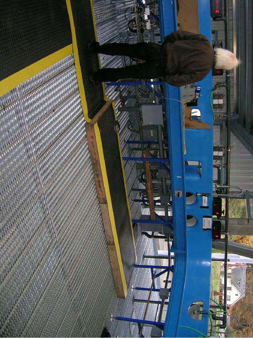
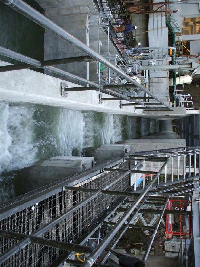
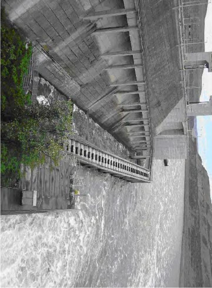
26 Additional research and additional design is recommended if this alternative is carried forward, yet the concept is understood well enough to perform the ranking relative to the other alternatives Upstream Passage Alt UP-4 Concrete Fish Ladder Alt UP-4 provides a Concrete Fish Ladder alternative as another style of volitional passage fishway that would allow fish to freely swim past the dam, or turn around and exit the fish ladder. The goal of this alternative is similar to that for the Nature-Like Channel; however, this concept utilizes an engineered structure that can be steeper and shorter than the channel alternative. Concrete fish ladders are common fish passage features at dams with proven success depending on the design species, the ladder style, height of the dam, length of the ladder, water quality, and other issues such as proper maintenance, avian and aquatic predators in or near the ladder, etc. While certain ladder designs are proven to be very successful for Pacific salmon, the certainty of passage for sturgeon is less clear. The same concern for lake sturgeon to be motivated to ascend the Concrete Ladder must be considered, as described above. Research done by the R2 design team identified aspects of fish ladders appropriate for sturgeon. R2 also developed initial guidelines to configure a concrete ladder for Keeyask based on the Ice Harbor style ladder known to pass large white sturgeon at The Dalles Dam in the US. The half- Ice Harbor style ladder shown on Drawing 14 includes baffles with an overflow weirs and a bottom orifice. This concept has the following characteristics: 90 steps at 23 cm height each, resulting in a total elevation gain of 20.7 metres. The Concrete Ladder would need to be at least 320 metres long, just to accommodate the number of pools necessary to ascend the 20.7 metre height. The concept illustrated on Drawing 14 is drawn at about 500 metres long to accommodate turning pools, and entrance/exit features. The alignment shown is simply to illustrate the necessary fish ladder length. Additional work to fit a concrete ladder alternative into the site and current design of the dam features would be required during future design phases. Special care must be taken to preserve access to the powerhouse via the north access road and the access door leading into the north side of the powerhouse. The slope of each ladder section is set at 6.25%. Overall slope may be less depending on how the ladder is fit into the site. The ladder design flow is 1.5 m3/s, calculated based on the orifice size and weir length shown with the 23 cm step height. 25
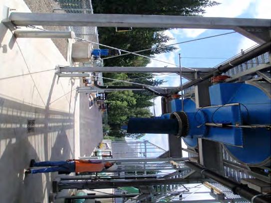
27 The Fish Collection Facility shown on Drawing 2 would be coupled to the ladder entrance, to lift fish from the bottom of the tailrace up to the tailrace water level (about 10 m). This is not a truly volitional feature; therefore, an alternate configuration with an entrance transition section could be added instead of the trap. This should be explored during future design phases, if this alternative is carried forward. A channel exit structure would be necessary to accommodate the 1.0 metre reservoir fluctuation, and maintain constant flow into the channel based on the pool and orifice step design, which needs a constant flow. This structure would require five pools with adjustable overflow gates, as shown on Drawing 14. If year-round use is desired, the flows in the ladder may not be sufficient to avoid freezing over in the winter months. A cover over the ladder or additional flow could be required to address freezing concerns. If year-round use is not desired, the Concrete Ladder would be more feasible to dewater and salvage fish than the Nature-Like Channel alternative. Sample photographs are provided on Drawing 14 to help illustrate the ladder concept, pool details, control gates at the exit, and how the ladder could traverse the dam. Like the Nature-Like Channel Alternative, additional research and design development is recommended if this alternative is carried forward Upstream Passage Alt UP-5 Lift or Lock to Passage Channel Alt UP-5 provides one concept for a Fish Lift or Lock, connected to the Fish Collection Facility shown at Entrance #1. The advantage of a lock or a lift style passage facility is typically a reduction in fish handling, and elimination of a truck transport as described with Alt UP-1. For example, fish could enter the Collection Facility, and be lifted through a fish lift or lock directly over the dam. The disadvantage of a dedicated trap is the fixed location associated with the trap, as a truck could release the fish at any point in the reservoir. However, the lock facility illustrated on Drawing 14 demonstrates the need to transport fish from the Collection Facility to the Lock Facility shown near the dam, which eliminates some of these advantages, as least for Entrance Locations #1 and #3 (see Drawing 1). Facilities shown on Drawing 14 include: The Collection Facility with an adjustable entrance and AWS, as described earlier. A transport channel where the fish could swim, or be crowded towards a lock/lift facility. Note that this transport channel could be configured to act as one style of a Challenge Section for this alternative. 26
28 A fish crowder is shown to help force fish into the fish lock. The Lock facility, shown as a circular style lock that would operate as follows: Fish would be crowded into an open gate, leading into the lock. The lock door would close, and screened water provided from the reservoir and controlled by valves would fill the lock up to the lake level. A brail (similar to a basket made of perforated plate material) would follow the water surface up as it rises, maintaining a relative depth of about 2.5 metres so the fish would remain at the same atmospheric pressure for the lift cycle. When full, release gate would be opened near the surface, and fish could swim, be crowded, or sluiced into Gull Lake through the release channel. The lock could then be drained in the reverse cycle, and the lift cycle repeated. A Release Channel would need further investigation to determine the safest and most reliable means to release the fish back into the forebay. For this site, a lift or lock alternative would be more amenable to the entrances located near the dam (UC Entrance Location 1 or 4, Drawing 1); however, the concept shown on Drawing 14 is sufficient to define the concept for evaluation. An alternative trap concept is shown in dashed lines on Drawing 14, which would provide more of a surface style, hopper/cart type fish lift. This concept would provide a cart on rails that could load fish directly from the Fish Sampling facility. Rather than using a truck for transport, the cart could be moved along the rails towards the dam, and then hoisted up inclined rails where it would park in a release structure and release the fish into the forebay. For Location UC #1, that style would likely be less costly, and would be feasible at this site. A tram style lift could also be feasible at this site. All of these style of lifts would be amenable to a phased approach, possibly starting with a trapand-transport facility with provisions to add a lock or trap feature in the future Upstream Passage Alt UP-6 Lift or Lock to Passage Channel with Challenge Section of Fishway Alt UP-6 is shown schematically on Drawing 16, with two potential locations for a Challenge Section. The Challenge Section shown to the east of the Fish Collection Facility is illustrated on Drawings 10 and 11. A similar challenge section could be provided in the Transport Channel leading from the Fish Collection Facility to the Fish Lock. This concept could be similarly added to a Lift or Lock concept at any of the entrance locations, and would also be more amenable to the north side of the tailrace entrances, or the south bank fishway entrance locations. 27
29 4.3 Downstream Collection and Passage Downstream fish passage considerations differ from upstream passage because even if no additional facilities are added to the project there will still be downstream passage through the turbines or spillway (when it is open). In fact, even with the addition of facilities to enhance downstream fish passage, fish will still pass downstream via the turbines. As such, the turbines have been designed with features to reduce injury and mortality of fish. When assessing impacts of fish passage through turbines and potential mitigation alternatives there are several factors that need to be considered: the size, speed, and design parameters of the turbines and the design of the trashracks at the turbine intakes. The Keeyask GS turbines have integrated consideration of a number of variables affecting fish passage survival in the selection and development processes. Although there are many variables to consider beyond those specifically relevant for fish survival (particularly efficiency and cost), a general objective for the Keeyask GS turbine selection and development is to achieve a minimum survival rate of 90% for fish as large as 500 mm. The turbines for the Keeyask GS are large-diameter, fixed-blade, propeller turbines operating at a low rotational speed. These features will enhance fish survival during passage. Details regarding specific design parameters are available within the Keeyask EIS. At smaller hydroelectric projects it is sometimes possible to screen all fish away from the turbines and divert them through a safe downstream bypass facility under all but flood flow conditions. This is accomplished through the use of full exclusionary screens, which screen all of the flow entering the turbines based on well established fish screening criteria designed to allow fish to maintain swimming control and orientation, so they may swim away from the screens and enter bypass systems. However, on larger rivers full exclusionary screening is typically not practical because screens sized to meet safe design standards for juvenile fish would need to be so large they would be nearly impossible to operate and maintain due to debris and ice loads, and would likely cause greater injury and mortality to small fish than passage through the turbines. This is especially true when fisheries features are integrated into the design of turbines, such as those planned for the Keeyask GS. For example full exclusionary screens designed to industry accepted criteria at Keeyask GS would require a screen area over 3.5 hectares (8.6 acres, based on National Marine Fisheries Service (NMFS)4 criteria of 0.4 feet per second approach velocity on an exclusionary screen with active screen cleaners), with multiple bypass systems and automated screen cleaners. This would be an extremely difficult screening system to operate and maintain, and screening systems of this size simply do not exist in the industry as they are considered infeasible. 28
30 Various other structural downstream passage alternatives were developed and examined as part of the feasibiliy study1. However, due to uncertainty regarding their likelihood of success and the immature state of technology for the downstream passage of the target species no alternatives were found which offered a viable option preferable to turbine passage. Because of this reality, the most suitable alternative for downstream passage is simply allowing fish to pass downstream in the turbine flow, taking advantage of the high survival rates afforded by the Keeyask turbine design. Subsequent stages of study may examine opportunities to add exclusionary techniques aimed at reducing the entrainment of larger fish at greater risk of injury or mortality due to turbine passage. 5.0 Summary and Conclusions This report summarizes the preliminary conceptual designs for opportunities to develop effective and practicable strategies that provide safe fish movement at the Keeyask GS site. The report provides context for the issues associated with fish passage facilities and identifies potential fish passage facilities with supporting technical information for future discussion and analysis as the design, construction and operation of the project moves forward. The remainder of this section includes a summary of the biological uncertainties associated with fish passage facilities at the Keeyask GS and recommendations for further consideration. 5.1 Biological Uncertainties While upstream and downstream fish passage facilities are an obvious consideration when protecting obligate anadromous fish populations such as Pacific salmon that must migrate between fresh and salt water to complete their life history, the benefit is not as clear when considering fish movements between freshwater habitats, such as the case at Keeyask GS. General ecological guidelines suggest that maintaining river connectivity enhances the viability of fish populations by providing access to critical habitats, reducing extinction risks, maintaining genetic diversity, or increasing the potential for recolonization after local extirpation. While these guidelines are well-supported in the scientific literature, they are neither site nor species-specific and should be considered in light of potential negative concerns associated with upstream passage. Concerns may include but are not limited to target species lacking migratory motivation, the passage of fish into marginal upstream habitats, and exposing fish to cumulative dam passage risks. Some fish may exhibit movements between freshwater habitats as part of foraging, spawning, or dispersal behavior, may exhibit movements while seeking temperature or other refugia, or may exhibit movements that appear random. Other fish may exhibit limited movements and complete their entire life cycle within a single reach or tributary. 29
31 The life stage, species and number of fish exhibiting directed upstream or downstream movements will affect the perception of fish passage facility success regardless of the size, design or operational characteristics of the facility. As indicated, based on monitoring studies completed to date the fish species present at the Keeyask site do not appear to be undertaking movement behaviors typical of migratory species, as a requirement of their life history. Fish can move up and down over the GS site, but movements appear to be more for foraging movements rather than activities such as spawning. However, uncertainty exists regarding the degree to which directed upstream and downstream movements are exhibited by each species and life stage in the Keeyask Study Area. Ideally, these and other relevant biological factors would be clearly understood and used in guiding subsequent engineering efforts to develop appropriate fish passage facility alternatives. However, given remaining biological uncertainties, an iterative approach is prudent in which uncertainties are resolved and passage facility alternatives are refined accordingly. 5.2 Recommendations Providing fish passage opportunities and facilities at the Keeyask project is a complex subject. The following observations and initial recommendations are provided on how to advance this subject Phased Approach General There are several uncertainties with fish behavior at the Keeyask site, especially with how they will behave following construction of the project. A common approach in the development of fish passage facilities is to prioritize these uncertainties relative to their importance to achieving project success. Based on these biological uncertainties, the development of a biological fish passage study plan to reduce uncertainties is recommended. It is also recommended that any Keeyask GS fish passage facility provisions to retrofit any sort of long term fish passage option such as those described herein, be designed with expansion and adaptability in mind, such that future studies could build on and use any base passage provisions. In addition, it is recommended that an iterative approach is used to refine the fish movement strategy that complements other aquatic resource measures Upstream Collection and Passage Facilities Based on the phased approach concept described above, it is recommended that a phased development of facilities be considered by providing provisions to: a) retrofit an initial fish collection facility; and b) for potential retrofit of upstream fish passage facility alternatives. As indicated, these provisions have been made through reserving land at 30
32 several locations adjacent to the GS as potential sites for the installation of a fish passage facility and installing non-functional closed structures in locations where it would be difficult (i.e., inaccessible and/or technically challenging) to construct a structure after the project is in place such that these structures could be opened if required. All potential sites would then be available for selection once the near-field information from postproject monitoring becomes available. The specific location and engineering details of any selected collection and upstream passage facilities and subsequent provisions for their retrofit would need to be refined through subsequent phases of the design process. It is recommended that a biological fish passage study plan be implemented that addresses the current unknowns and concern regarding upstream collection and passage of these freshwater species. The Keeyask Aquatic Effects Monitoring Plan will describe initial studies designed to collect data on movements for the key species as they approach the GS. Through recent discussions with regulators a commitment has been made to undertake a collaborative process to develop an experimental program to investigate near field fish behavior, including that of fish caught below the GS and moved to upstream locations. This will assist in optimizing the best location to retrofit an upstream fish collection facility or upstream passage facility at the Keeyask GS, once constructed, if it is determined that it is necessary to support the fish populations associated with the new ecosystem created by the project Downstream Passage The turbine and spillway passage routes noted are expected to deal appropriately with downstream fish passage. Due to uncertainty regarding their likelihood of success and the immature state of technology for the downstream passage of the target species, no alternatives were found which offered a viable option preferable to turbine passage. Because of this reality, the most suitable alternative for downstream passage is simply allowing fish to pass downstream in the turbine flow, taking advantage of the high survival rates afforded by the Keeyask turbine design. 31
33 References 1. R2 Resource Consultants, Inc Keeyask Fish Passage Draft Phase 1 Report Feasibility Study. Prepared by R2 Resource Consultants, Inc., in association with Kozmo Inc. November Peake, S Feasibility, conceptual design, and likelihood of success associated with engineering and natural structures for upstream and downstream passage of lake sturgeon at new hydroelectric facilities in Manitoba. A report prepared for Manitoba Hydro. 3. Peake, S Information on the effectiveness of existing nature-like bypass channels in providing upstream and downstream passage, and productive habitat, for fish species. A report prepared for Manitoba Hydro. 4. National Marine Fisheries Service (NMFS) Anadromous Salmonid Passage Facility Design. NMFS, Northwest Region. Information available on line at: July
34 Design Concept Drawings
35
36
37
38
39
40
41
42
43
44
45
46
47
48
Annex C Temporary Fish Passage Plan
 Annex C Temporary Fish Passage Plan Table C1 Figure C1 Figure C2 Figure C3 Figure C4 Figure C5 Figure C6 Figure C7 Figure C8 Figure C9 Figure C10 Figure C11 Figure C12 Figure C13 Options Considered in
NUMERICAL AND PHYSICAL MODELING
 POINTE DU BOIS GENERATING STATION SPILLWAY REPLACEMENT PROJECT NUMERICAL AND PHYSICAL MODELING Kara Hurtig, Northwest Hydraulic Consultants, North Vancouver, BC, Canada David S. Brown, KGS Group, Winnipeg,
Packwood Lake Intake Screen Velocity Test Report for Energy Northwest's Packwood Lake Hydroelectric Project FERC No Lewis County, Washington
 for Energy Northwest's Packwood Lake Hydroelectric Project FERC No. 2244 Lewis County, Washington Submitted to P.O. Box 968 Richland, Washington 99352-0968 Submitted by EES Consulting 1155 North State
Upstream Passage Assessment of American Shad Using 3D Acoustic Telemetry
 Upstream Passage Assessment of American Shad Using 3D Acoustic Telemetry Timothy Hogan, Alden Research Laboratory Corey Wright, Blue Leaf Environmental Skip Medford, Enel Green Power North America Abstract
Applying Engineering Solutions to the Science of Protection and Enhancement of Aquatic Environments. Bill Holman, P.E. Stanley Consultants
 Applying Engineering Solutions to the Science of Protection and Enhancement of Aquatic Environments Bill Holman, P.E. Stanley Consultants Project Development PHASE STAGE TASKS PURPOSE I II III Investigation
Session C9: Priest Rapids Fish Bypass: A Case Study from Start to Finish
 University of Massachusetts - Amherst ScholarWorks@UMass Amherst International Conference on Engineering and Ecohydrology for Fish Passage International Conference on Engineering and Ecohydrology for Fish
Applying Engineering Solutions to the Science of Invasive Aquatic Species Control Asian Carp and Sea Lamprey. Bill Holman, P.E. Stanley Consultants
 Applying Engineering Solutions to the Science of Invasive Aquatic Species Control Asian Carp and Sea Lamprey Bill Holman, P.E. Stanley Consultants Sea Lamprey: Great Lakes Invader Lake Superior Sea Lamprey
BULL TROUT OPERATIONAL PLAN
 BULL TROUT OPERATIONAL PLAN ROCKY REACH HYDROELECTRIC PROJECT FERC Project No. 2145 April 10, 2001 Public Utility District No. 1 of Chelan County Wenatchee, Washington BULL TROUT OPERATIONAL PLAN This
APPENDIX 2.1 Lake Sturgeon - Mitigation and Enhancement
 APPENDIX 2.1 Lake Sturgeon - Mitigation and This page is intentionally left blank. Lake Sturgeon Mitigation and As a provincial crown corporation providing electric energy and natural gas service, Manitoba
Guidance Note. Hydropower Guidance Note: HGN 8 Fish Passage. When do you need to install a fish pass?
 Guidance Note Hydropower Guidance Note: This guidance note is not intended as a statement of law. It should be read in combination with, and in the context of, the relevant enactments and EU obligations.
ADULT FISHWAY INSPECTIONS ON THE COLUMBIA AND SNAKE RIVERS 2012 ANNUAL REPORT
 ADULT FISHWAY INSPECTIONS ON THE COLUMBIA AND SNAKE RIVERS 2012 ANNUAL REPORT David A. Benner, Field Operations Coordinator Fish Passage Center A Collaborative Program of United States Fish and Wildlife
USING A LABYRINTH WEIR TO INCREASE HYDRAULIC CAPACITY. Dustin Mortensen, P.E. 1 Jake Eckersley, P.E. 1
 USING A LABYRINTH WEIR TO INCREASE HYDRAULIC CAPACITY Dustin Mortensen, P.E. 1 Jake Eckersley, P.E. 1 Plum Creek Floodwater Retarding Structure No. 6 is located in an area of Kyle, Texas, that is currently
TECHNICAL MEMORANDUM 002 EMORANNO. 001
 TECHNICAL MEMORANDUM 002 EMORANNO. 001 To: Jack Synder, P.E. EES Consulting From: Mort McMillen, P.E. Paul Larson, SE Date: October 13, 2010 Project: Cc: Taylor Bowen Subject: Technical Memorandum (TM)
Project Award Presentation
 University of Massachusetts Amherst ScholarWorks@UMass Amherst International Conference on Engineering and Ecohydrology for Fish Passage International Conference on Engineering and Ecohydrology for Fish
Downstream Fish Passage Reports from the Field
 Downstream Fish Passage Reports from the Field Northwest Hydroelectric Association Fall Workshop Two World Trade Center, Portland, OR October 17, 2013 TODAY S PANEL MEMBERS Steve Fischer, PE, Tacoma Power
Attached as Exhibit B-2 is BC Hydro's presentation from the Stave Falls Spillway Gates Project Workshop held on January 18, 2010.
 BChydro CD FOR GEf\lE IONS B-2 Joanna Sofield Chief Regulatory Officer Phone: (604) 623-4046 Fax: (604) 623-4407 bchydroregulatorygroup@bchydro.com January 19, 2010 Ms. Erica M. Hamilton Commission Secretary
FINAL Caples Lake Fisheries Management Plan. Version 4.0
 FINAL Caples Lake Fisheries Management Plan Version 4.0 August 15, 2008 Purpose The Caples Lake Fisheries Management Plan (Plan) outlines the stocking plan to reestablish a sport fishery in Caples Lake
Existing vs. Purpose-built Barriers for Sea Lamprey Control
 Existing vs. Purpose-built Barriers for Sea Lamprey Control Existing Structures were originally built for purposes other than blocking sea lamprey and are important to sea lamprey control and are more
ENTRANCES USED AND PASSAGE THROUGH FISHWAYS FOR ADULT CHINOOK SALMON AND STEELHEAD
 ENTRANCES USED AND PASSAGE THROUGH FISHWAYS FOR ADULT CHINOOK SALMON AND STEELHEAD Part III of Final Report for MIGRATION OF ADULT CHINOOK SALMON AND STEELHEAD PAST DAMS AND THROUGH RESERVOIRS IN THE LOWER
Savannah River, Georgia and South Carolina
 Scope of Work for Use of the Fish Bypass at New Savannah Bluff Lock and Dam for the Savannah Harbor Expansion Project Monitoring and Adaptive Management Program Savannah River, Georgia and South Carolina
Final Fish Salvage & Temporary Tailrace Barrier Report for the Wallowa Falls Hydroelectric Project Tailrace. (FERC No. P-308) December 18, 2017
 December 18, 2017") Final for the Wallowa Falls Hydroelectric Project Tailrace (FERC No. P-308) December 18, 2017 Prepared by: Jeremiah Doyle PacifiCorp 825 NE Multnomah Street Portland, OR 97232 December 18, 2017 Page 1
Final for the Wallowa Falls Hydroelectric Project Tailrace (FERC No. P-308) December 18, 2017 Prepared by: Jeremiah Doyle PacifiCorp 825 NE Multnomah Street Portland, OR 97232 December 18, 2017 Page 1
Spilling Water at Hydroelectric Projects in the Columbia and Snake Rivers How Does It Benefit Salmon?
 Spilling Water at Hydroelectric Projects in the Columbia and Snake Rivers How Does It Benefit Salmon? Hydropower development in the Columbia and Snake rivers has left its mark on salmonid populations,
STRUCTURAL STABILITY ASSESSMENT
 STRUCTURAL STABILITY ASSESSMENT CFR 257.73(d) Fly Ash Reservoir II Cardinal Plant Brilliant, Ohio October, 2016 Prepared for: Cardinal Operating Company Cardinal Plant Brilliant, Ohio Prepared by: Geotechnical
Final Fish Salvage & Temporary Tailrace Barrier Report for the Wallowa Falls Hydroelectric Project Tailrace. (FERC No. P-308) December 20, 2018
 December 20, 2018") Final Fish Salvage & Temporary Tailrace Barrier Report for the Wallowa Falls Hydroelectric Project Tailrace (FERC No. P-308) December 20, 2018 Prepared by: Jeremiah Doyle PacifiCorp 825 NE Multnomah Street
Final Fish Salvage & Temporary Tailrace Barrier Report for the Wallowa Falls Hydroelectric Project Tailrace (FERC No. P-308) December 20, 2018 Prepared by: Jeremiah Doyle PacifiCorp 825 NE Multnomah Street
Within Phase I, researchers have identified four tasks that they think are essential for designing the most informative study.
 Revised Study Plan June 30, 2005 I. Introduction The Merwin upstream fish passage facility was originally completed with construction of the Merwin Dam. This trapping facility historically operated with
2016 Annual Work Plan
 Rocky Reach Hydroelectric Project FERC No. 2145 2016 Annual Work Plan 2015 Progress Report d per Rocky Reach Settlement Agreement, Sections 15.1.1 & 15.6.5 Reports provided by Chelan PUD Leads: Ray Heit
Steve Hemstrom Sr. Fisheries Biologist Chelan PUD Natural Resources Desk: Cell:
 From: To: Cc: Subject: Date: Attachments: Hemstrom, Steven "Lewis, Stephen" Sokolowski, Rosana 2014 Rocky Reach Bull Trout Report Wednesday, June 18, 2014 3:01:07 PM Final 2014 Rocky Reach Bull Trout Observations
ADULT FISHWAY INSPECTIONS ON THE COLUMBIA AND SNAKE RIVERS 2016 ANNUAL REPORT
 ADULT FISHWAY INSPECTIONS ON THE COLUMBIA AND SNAKE RIVERS 2016 ANNUAL REPORT David A. Benner, Field Operations Coordinator FISH PASSAGE CENTER A Collaborative Program of United States Fish and Wildlife
107 FERC 61,282 UNITED STATES OF AMERICA FEDERAL ENERGY REGULATORY COMMISSION
 107 FERC 61,282 UNITED STATES OF AMERICA FEDERAL ENERGY REGULATORY COMMISSION Before Commissioners: Pat Wood, III, Chairman; Nora Mead Brownell, and Joseph T. Kelliher. Public Utility District No. 1 of
Packwood Hydroelectric Project Barrier Analysis December 12, 2006
 Packwood Hydroelectric Project Barrier Analysis December 12, 2006 Study Area Natural barriers to upstream fish passage on Lake Creek at RM 1.03 and RM 1.95 Snyder Creek culvert under the Project tailrace
Ermenek Dam and HEPP: Spillway Test & 3D Numeric-Hydraulic Analysis of Jet Collision
 Ermenek Dam and HEPP: Spillway Test & 3D Numeric-Hydraulic Analysis of Jet Collision J.Linortner & R.Faber Pöyry Energy GmbH, Turkey-Austria E.Üzücek & T.Dinçergök General Directorate of State Hydraulic
4.6 LAKE STURGEON SPAWNING HABITAT DOWNSTREAM OF POWERHOUSE
 Sand Blanket Material Shields curves related to sand particle size and depth-averaged velocities in the post-project reservoir environment obtained from MIKE21 modeling were used to model the erosion potential
SPILLWAY REPLACEMENT PROJECT NUMERICAL AND PHYSICAL MODELING. Kara Hurtig, Water Resources Engineer, Northwest Hydraulic Consultants, BC, Canada
 POINTE DU BOIS GENERATING STATION SPILLWAY REPLACEMENT PROJECT NUMERICAL AND PHYSICAL MODELING Kara Hurtig, Water Resources Engineer, Northwest Hydraulic Consultants, BC, Canada David S. Brown, Senior
Greenup Lock Filling and Emptying System Study
 Fourth LACCEI International Latin American and Caribbean Conference for Engineering and Technology (LACCET 2006) Breaking Frontiers and Barriers in Engineering: Education, Research and Practice 21-23 June
Plate 21: Vertical slot fishway retrofitted to a small power plant.
 34 Vertical slot fishways The basic design of a vertical slot fishway is a rectangular channel partitioned by baffles into resting pools. When the water is flowing the fish swim from pool to pool through
FISH PASSAGE CENTER 847 NE 19 th Avenue, #250, Portland, OR Phone: (503) Fax: (503) us at
 Fax: (503) us at") FISH PASSAGE CENTER 847 NE 19 th Avenue, #250, Portland, OR 97232 Phone: (503) 833-3900 Fax: (503) 232-1259 www.fpc.org/ e-mail us at fpcstaff@fpc.org MEMORANDUM TO: FROM: FPAC David A. Benner DATE: October
FISH PASSAGE CENTER 847 NE 19 th Avenue, #250, Portland, OR 97232 Phone: (503) 833-3900 Fax: (503) 232-1259 www.fpc.org/ e-mail us at fpcstaff@fpc.org MEMORANDUM TO: FROM: FPAC David A. Benner DATE: October
STRUCTURE S-65 PURPOSE SPILLWAY OPERATION
 STRUCTURE S-65 This structure is a reinforced concrete, gated spillway with discharge controlled by three cable operated, vertical lift gates, and a reinforced concrete lock structure with two pairs of
ADULT FISHWAY INSPECTIONS ON THE COLUMBIA AND SNAKE RIVERS 2013 ANNUAL REPORT
 ADULT FISHWAY INSPECTIONS ON THE COLUMBIA AND SNAKE RIVERS 2013 ANNUAL REPORT David A. Benner, Field Operations Coordinator Fish Passage Center A Collaborative Program of United States Fish and Wildlife
Trout Unlimited Comments on the Scope of Environmental Impact Statement for the Constitution Pipeline Project, Docket No. PF12-9
 October 9, 2012 Kimberly D. Bose, Secretary Federal Energy Regulatory Commission 888 First Street, NE, Room 1A Washington, DC 20426 RE: Trout Unlimited Comments on the Scope of Environmental Impact Statement
APPENDIX J HYDROLOGY AND WATER QUALITY
 APPENDIX J HYDROLOGY AND WATER QUALITY J-1 Technical Report on Airport Drainage, Northern Sector Airport and Ordinance Creek Watershed / Preliminary Creek Constructed Natural Channel Culvert J-2 Preliminary
Technical Report 99-4 EFFECTS OF A SHAD FISHERY ON PASSAGE OF ADULT CHINOOK SALMON THROUGH THE OREGON-SHORE FISHWAY LADDER AT THE DALLES DAM
 Technical Report 99-4 EFFECTS OF A SHAD FISHERY ON PASSAGE OF ADULT CHINOOK SALMON THROUGH THE OREGON-SHORE FISHWAY LADDER AT THE DALLES DAM - 1996 A report for Project MPE-P-95-1 by C.A. Peery, T.C. Bjornn,
SUMMARY OF OPERATIONS AT THE SAFE HARBOR FISH PASSAGE FACILITY SPRING 2017
 SUMMARY OF OPERATIONS AT THE SAFE HARBOR FISH PASSAGE FACILITY SPRING 2017 November 2017 SUMMARY OF OPERATIONS AT THE SAFE HARBOR FISH PASSAGE FACILITY SPRING 2017 Prepared for SAFE HARBOR WATER POWER
Lewis River Fish Passage Program 2014 Annual Report (30-day review Draft)
") Lewis River Fish Passage Program 2014 Annual Report (30-day review Draft) FERC Project Nos. 935, 2071, 2111, 2213 Merwin Fish Collection Facility Adult Holding Tank 2014 Photo by Chris Karchesky PacifiCorp
Lewis River Fish Passage Program 2014 Annual Report (30-day review Draft) FERC Project Nos. 935, 2071, 2111, 2213 Merwin Fish Collection Facility Adult Holding Tank 2014 Photo by Chris Karchesky PacifiCorp
Susitna-Watana Hydroelectric Project (FERC No ) Salmon Escapement Study Study Plan Section 9.7
 Salmon Escapement Study Study Plan Section 9.7") (FERC No. 14241) Salmon Escapement Study Study Plan Section 9.7 Part D: Supplemental Information to June 2014 Initial Study Report Prepared for Prepared by LGL Alaska Research Associates, Inc. & Alaska
(FERC No. 14241) Salmon Escapement Study Study Plan Section 9.7 Part D: Supplemental Information to June 2014 Initial Study Report Prepared for Prepared by LGL Alaska Research Associates, Inc. & Alaska
California Conference of Directors of Environmental Health Recreational Health Technical Advisory Committee September 17, 2003
 California Conference of Directors of Environmental Health Recreational Health Technical Advisory Committee September 17, 2003 RECREATIONAL WATER PARKS GUIDELINES Definitions. ACTIVITY POOL means a pool
Migration Behavior of Adult Pacific Lamprey in the Lower Columbia River and Evaluation of Bonneville Dam Modifications to Improve Passage, 2002.
 Migration Behavior of Adult Pacific Lamprey in the Lower Columbia River and Evaluation of Bonneville Dam Modifications to Improve Passage, 2002. Mary L. Moser Fish Ecology Division, Northwest Fisheries
Big Spring Creek Habitat Enhancement and Fishery Management Plans
 Big Spring Creek Habitat Enhancement and Fishery Management Plans November 5, 2012 Big Spring Events and Activities Center Newville, PA Charlie McGarrell Regional Habitat Biologist Pennsylvania Fish and
FINAL REPORT. Yonkers Creek Migration Barrier Removal Project Wonderstump Road Del Norte County. Submitted By:
 FINAL REPORT Yonkers Creek Migration Barrier Removal Project Wonderstump Road Del Norte County Submitted By: Del Norte County Community Development Department Yonkers Creek Migration Barrier Removal Project
Proposed Study Plan 1100 ft Whooshh Fish Transport System. June 2016
 Proposed Study Plan 1100 ft Whooshh Fish Transport System June 2016 Purpose To conduct a feasibility/viability study to evaluate the efficacy of employing a Whooshh Fish Transport System (WFTS) to safely
MANERI DAM D/S VIEW. Er. SANDEEP SINGHAL Director (Projects) UJVN Limited, Dehradun, (UK)
 UJVN Limited, Dehradun, (UK)") COMPREHENSIVE REHABILITATION / REPAIR OF MANERI DAM IN DIST. UTTARKASHI MANERI DAM D/S VIEW Er. SANDEEP SINGHAL Director (Projects) UJVN Limited, Dehradun, (UK) sandysinghal14@hotmail.com ABSTRACT Severe
COMPREHENSIVE REHABILITATION / REPAIR OF MANERI DAM IN DIST. UTTARKASHI MANERI DAM D/S VIEW Er. SANDEEP SINGHAL Director (Projects) UJVN Limited, Dehradun, (UK) sandysinghal14@hotmail.com ABSTRACT Severe
DAIVÕES DAM SPILLWAY: A NOVEL SOLUTION FOR THE STILLING BASIN
 DAIVÕES DAM SPILLWAY: A NOVEL SOLUTION FOR THE STILLING BASIN Elsa Alves *, Felix Hernando and Rafael Chacón * Laboratório Nacional de Engenharia Civil (LNEC) Av. do Brasil, 101, 1700-066 Lisboa, Portugal
Lake Sturgeon Stewardship and Enhancement Program
 Lake Sturgeon Stewardship and Enhancement Program Report # 11-05 Construction of Shoals to Enhance Lake Sturgeon Spawning Habitat in the Winnipeg River at Pointe du Bois: 2011 Monitoring Program Report
MEMORANDUM. DATE: June 15, RE: Fishway Inspections May 2001
 FISH PASSAGE CENTER 2501 SW First Avenue, Suite 230, Portland, OR 97201-4752 Phone: (503) 230-4099 Fax: (503) 230-7559 http://www.fpc.org/ e-mail us at fpcstaff@fpc.org MEMORANDUM TO: FROM: Salmon Managers
Operation and Maintenance Manual. First Defense and First Defense High Capacity. Vortex Separator for Stormwater Treatment
 Operation and Maintenance Manual First Defense and First Defense High Capacity Vortex Separator for Stormwater Treatment Page 2 Page 3 Table of Contents I. First Defense by Hydro International 3 First
Discussion on the Selection of the Recommended Fish Passage Design Discharge
 Discussion on the Selection of the Recommended Fish Passage Design Discharge Introduction The provision of fish passage is a requirement for most proposed culvert and bridge installations in Alberta, depending
Date: 25 September Introduction
 To: David Clugston, USACE Portland District From: Matt Keefer, Eric Johnson, Tami Clabough, Mike Jepson, Chris Caudill, Mary Moser RE: Preliminary evaluation of radiotelemetry and half-duplex PIT tag data
Micro Hydropower and Fish.
 Micro Hydropower and Fish. Garry O Neill. Senior Fisheries Officer. Inland Fisheries Branch. 1. Value of Fisheries. 2. Life cycle of the Salmon. 3. Potential impacts of Hydro s on Fish. 4. Fisheries Legislation.
Juvenile salmon survivals in 2017 and river conditions
 FISH PASSAGE CENTER 847 NE 19 th Ave., Suite 250, Portland, OR 97213 Phone: (503) 833-3900 Fax: (503) 232-1259 http://www.fpc.org/ e-mail us at fpcstaff@fpc.org MEMORANDUM TO: FROM: Ed Bowles (ODFW) FPC
Prospect No. 3 Hydroelectric Project FERC Project No. P Fish Passage Facilities Study Report: Biological Evaluation
 Prospect No. 3 Hydroelectric Project FERC Project No. P-2337 Fish Passage Facilities Study Report: Biological Evaluation Study Objectives Determine if Project fish passage facilities are biologically functional
Monitoring of Downstream Fish Passage at Cougar Dam in the South Fork McKenzie River, Oregon February 8, By Greg A.
 Monitoring of Downstream Fish Passage at Cougar Dam in the South Fork McKenzie River, Oregon 1998- February 8, 2 By Greg A. Taylor Oregon Dept. of Fish & Wildlife 315 E. Main Street Springfield, OR 97478
JAP Additional Information Sheet
 JAP Additional Information Sheet Block 15: Purpose and Need The USACE purpose of the project is to provide a safe and reliable whitewater park for the recreational public in a city park, which will provide
Columbia Lake Dam Removal Project
 Columbia Lake Dam Removal Project The Columbia Lake dam located 1/4 mile upstream of the Paulins Kill River's confluence with the Delaware River in Knowlton Township, Warren County has been proposed for
ADULT FISHWAY INSPECTIONS ON THE COLUMBIA AND SNAKE RIVERS 2000 ANNUAL REPORT. Larry R. Basham, Field Operations Coordinator
 ADULT FISHWAY INSPECTIONS ON THE COLUMBIA AND SNAKE RIVERS 2000 ANNUAL REPORT Larry R. Basham, Field Operations Coordinator FISH PASSAGE CENTER 2501 SW First Ave., Suite 230 Portland, OR 97201-4752 of
FSOC Upstream Fish Passage Guidance Document
 FSOC Upstream Fish Passage Guidance Document STEP 1: Identify species and life stages in need of fish passage STEP 2: Identify fishway options and species applicability STEP 3 Fish passage criteria review
U.S. ARMY CORPS OF ENGINEERS WALLA WALLA DISTRICT FISH FACILITIES WEEKLY REPORT # Turbine Operation
 U.S. ARMY CORPS OF ENGINEERS WALLA WALLA DISTRICT FISH FACILITIES WEEKLY REPORT #32-2018 Project: McNary Biologist: Bobby Johnson and Denise Griffith Dates: October 5 to 11, 2018 Turbine Operation Yes
From: Michael A. Jepson, Tami C. Clabough, and Christopher C. Caudill
 To: Derek Fryer, USACE Walla Walla District From: Michael A. Jepson, Tami C. Clabough, and Christopher C. Caudill RE: Evaluation of Radio-tagged Adult Chinook Salmon Behavior in Response to Nighttime Flow
Stream Crossings I: Engineering and Design Approaches to Provide Fish Passage at Culvert Slipline Projects in Connecticut
 University of Massachusetts - Amherst ScholarWorks@UMass Amherst International Conference on Engineering and Ecohydrology for Fish Passage International Conference on Engineering and Ecohydrology for Fish
Aquatic Facilities Water Spray/Play Ground Application, Design & Operating Requirements Environmental Health Guide
 Aquatic Facilities Water Spray/Play Ground Application, Design & Operating Requirements Environmental Health Guide Water Play/Spray Grounds are aquatic facilities where patrons (primarily children) become
Five Counties Salmonid Conservation Program - Fish Passage Design Workshop. February 2013
 Program - Aquatic Organisms and Stream Crossings Ecological Connectivity A watershed is a network of channels that drain a common boundary. Channel characteristics formed by interaction of precipitation,
Development and Investigation of Downstream Passage Alternatives for Cougar Dam, South Fork McKenzie River, OR
 Development and Investigation of Downstream Passage Alternatives for Cougar Dam, South Fork McKenzie River, OR Mike Langeslay Supervisory Fish Biologist Portland District March 18 th, 2014 US Army Corps
U.S. ARMY CORPS OF ENGINEERS WALLA WALLA DISTRICT FISH FACILITIES WEEKLY REPORT # Turbine Operation
 Project: McNary Biologist: Bobby Johnson and Denise Griffith Dates: October 12 to 18, 2018 U.S. ARMY CORPS OF ENGINEERS WALLA WALLA DISTRICT FISH FACILITIES WEEKLY REPORT #33-2018 Turbine Operation Yes
Can we attract lake sturgeon to a fishway?
 University of Massachusetts - Amherst ScholarWorks@UMass Amherst International Conference on Engineering and Ecohydrology for Fish Passage International Conference on Engineering and Ecohydrology for Fish
Assessing Fish Condition After Passage Through Conventional and Fish-Friendly Turbines Using a Release Recapture Technique
 Assessing Fish Condition After Passage Through Conventional and Fish-Friendly Turbines Using a Release Recapture Technique Paul Heisey, Chris Avalos, and Joanne Fulmer Normandeau Associates, Inc. Drumore,
Lecture 10 : Sewer Appurtenances
 1 P age Module 8 : Sewer Appurtenances Lecture 10 : Sewer Appurtenances 2 P age The structures, which are constructed at suitable intervals along the sewerage system to help its efficient operation and
February Lower Granite Dam
 Lower Granite Dam 1. Fish Passage Information. The locations of fish passage facilities at Lower Granite Lock and Dam are shown in Figure LWG-1. Dates of project operations for fish purposes and special
Session B7 - Santee-Cooper: A Lock on Fish Passage Success
 University of Massachusetts - Amherst ScholarWorks@UMass Amherst International Conference on Engineering and Ecohydrology for Fish Passage International Conference on Engineering and Ecohydrology for Fish
Union Pacific Railroad
 Input Questions: 404/401 Pre Application Meeting, December 18, 2013, Portland, Oregon 1. What is the project purpose and need? The purpose of the project is to improve the efficiency and average velocity
OKANAGAN RIVER RESTORATION INITIATIVE - FAQ
 OKANAGAN RIVER RESTORATION INITIATIVE - FAQ Initiative background: The health of the q awsitk w (Okanagan River) has been severely impacted by the channelization works that occurred in the mid-1950 s.
FISH PASSAGE CENTER 847 NE 19 th Avenue, #250, Portland, OR Phone: (503) Fax: (503) us at
 Fax: (503) us at") FISH PASSAGE CENTER 847 NE 19 th Avenue, #250, Portland, OR 97232 Phone: (503) 833-3900 Fax: (503) 232-1259 www.fpc.org/ e-mail us at fpcstaff@fpc.org MEMORANDUM TO: FROM: FPAC David A. Benner DATE: June
FISH PASSAGE CENTER 847 NE 19 th Avenue, #250, Portland, OR 97232 Phone: (503) 833-3900 Fax: (503) 232-1259 www.fpc.org/ e-mail us at fpcstaff@fpc.org MEMORANDUM TO: FROM: FPAC David A. Benner DATE: June
Upstream Fish Passage Technologies for Managed Species
 Atlantic States Marine Fisheries Commission Fish Passage Working Group Upstream Fish Passage Technologies for Managed Species September 2010 The Atlantic States Marine Fisheries Commission (ASMFC) manages
Annex P Water Well Modification Plan
 Annex P Water Well Modification Plan Table P1 Table P2 Summary of data Concerning Wells Sampled Summary of New Pump Characteristics H:\WP\1346\Appendices\FEIS\D - Drawdown\CamRdy\App_D.doc Annex P: Water
BACK PRESSURE / SUSTAINING
 In many liquid piping systems, it is vital that line pressure is maintained within relatively narrow limits. This is the function of the 108 Pressure Relief / Back Pressure Series of the OCV control valves.
ADULT FISHWAY INSPECTIONS 2001 ANNUAL REPORT
 ADULT FISHWAY INSPECTIONS 2001 ANNUAL REPORT By LARRY R. BASHAM FISH PASSAGE CENTER of the COLUMBIA BASIN FISH & WILDLIFE AUTHORITY Bonneville: WA Shore Powerhouse Bonneville: WA Shore Fish Ladder Exit
Final Bull Trout Redd Monitoring Report for the Wallowa Falls Hydroelectric Project
 Final for the Wallowa Falls Hydroelectric Project East Fork Wallowa River barrier to upstream fish migration, photo courtesy of Kendrick Moholt (FERC No. P-308) December 18, 2017 Prepared by: Jeremiah
FISH PROTECTION STRUCTURES AND FISH PASSAGE FACILITIES. Toshio Hirose The honorary member of the Japan Society of Civil Engineers, Japan UNESCO EOLSS
 FISH PROTECTION STRUCTURES AND FISH PASSAGE FACILITIES Kyohei Baba University of Tokyo, Japan Toshio Hirose The honorary member of the Japan Society of Civil Engineers, Japan Keywords: specific fish population,
STRUCTURE 65-B PURPOSE SPILLWAY OPERATION
 STRUCTURE 65-B This structure is a reinforced concrete, gated spillway with discharge controlled by three cable operated vertical lift gates and a reinforced concrete lock structure with two pairs of sector
Final Bull Trout Genetics Monitoring Plan for the Wallowa Falls Hydroelectric Project. (FERC No. P-308) June 2017
 June 2017") Final for the Wallowa Falls Hydroelectric Project (FERC No. P-308) June 2017 Prepared by: Jeremiah Doyle PacifiCorp 825 NE Multnomah Street Portland, OR 97232 June, 2017 Page 1 of 8 Table of Contents 1.0
Final for the Wallowa Falls Hydroelectric Project (FERC No. P-308) June 2017 Prepared by: Jeremiah Doyle PacifiCorp 825 NE Multnomah Street Portland, OR 97232 June, 2017 Page 1 of 8 Table of Contents 1.0
Kootenai River Habitat Restoration Program. Kootenai Tribe of Idaho - January 27, 2014 Presentation for Kootenai Valley Resource Initiative
 Kootenai River Habitat Restoration Program Kootenai Tribe of Idaho - January 27, 2014 Presentation for Kootenai Valley Resource Initiative Decline of native species Kootenai River White Sturgeon ENDANGERED
Fremont Weir Fish Passage Proof of Concept. Final Engineering Report
 Department of Water Resources FloodSAFE Environmental Stewardship and Statewide Resources Office Fish Passage Improvement Program Fremont Weir Fish Passage Proof of Concept Final Engineering Report This
BACK PRESSURE / SUSTAINING
 SPECIFICATIONS DIMENSIONS In many liquid piping systems, it is vital that line pressure is maintained within relatively narrow limits. This is the function of the 108 Pressure Relief / Back Pressure Series
Hydraulic Modeling of Stream Enhancement Methods
 Hydraulic Modeling of Stream Enhancement Methods Matthew J. Curry John J. Levitsky Abstract Development within watersheds increases the amounts of runoff causing stream erosion and degradation of stream
Evaluation of Volitional Entry and Passage of Adult Pacific Salmonids through a Novel Fish Passage Technology
 Evaluation of Volitional Entry and Passage of Adult Pacific Salmonids through a Novel Fish Passage Technology BRIAN J. BELLGRAPH, ALISON H. COLOTELO, TIM J. LINLEY, LYSEL J. GARAVELLI, BRIANA M. RHODE,
Technical Report Culvert A Hydraulic Analysis
 DATE: November 3, 2011 Technical Report Culvert A Hydraulic Analysis TO: FROM: RE: Jim Reiser, P.E. Project Manager Parsons Brinckerhoff, Inc. Kurt Killian, P.E., CFM Parsons Brinckerhoff, Inc. Design
Endangered Species Act and FERC Hydroelectric Projects. Jeff Murphy & Julie Crocker NHA New England Meeting November 16, 2010
 Endangered Species Act and FERC Hydroelectric Projects Jeff Murphy & Julie Crocker NHA New England Meeting November 16, 2010 Shortnose Sturgeon Federally listed as endangered in 1967 Listed under the sole
COLUMBIA LAKE DAM REMOVAL PROJECT
 COLUMBIA LAKE DAM REMOVAL PROJECT Major Goals of the Columbia Lake Dam Removal: Reconnect 10 miles of the Paulins Kill River to the Delaware River, restoring natural flow regime and sediment transport.
7.0 FISH PASSAGE PLANNING AND EVALUATION
 7.0 FISH PASSAGE PLANNING AND EVALUATION One of the study elements contained in this section is the Anadromous Fish Passage Modeling. The Habitat Modeling Group, established to guide this study element,
145 FERC 62,070 UNITED STATES OF AMERICA FEDERAL ENERGY REGULATORY COMMISSION
 145 FERC 62,070 UNITED STATES OF AMERICA FEDERAL ENERGY REGULATORY COMMISSION Public Utility District No. 1 of Douglas County, Washington Project No. 2149-163 ORDER APPROVING BULL TROUT STRANDING, ENTRAPMENT,
Designing Labyrinth Spillways for Less than Ideal Conditions Real World Application of Laboratory Design Methods
 Designing Labyrinth Spillways for Less than Ideal Conditions Real World Application of Laboratory Design Methods Gregory Richards, P.E., CFM, Gannett Fleming, Inc. Blake Tullis, Ph.D., Utah Water Research
P U B L I C U T I L I T Y D I S T R I C T N O.
 P U B L I C U T I L I T Y D I S T R I C T N O. 1 o f C H E L A N C O U N T Y P.O. Box 1231, Wenatchee, WA 98807-1231 327 N. Wenatchee Ave., Wenatchee, WA 98801 (509) 663-8121 Toll free 1-888-663-8121 www.chelanpud.org
GUARDIAN EQUIPMENT Emergency Eye Wash and Shower Equipment. ANSI Z358.1 Compliance Checklist
 GUARDIAN EQUIPMENT Emergency Eye Wash and Shower Equipment ANSI Z358.1 Compliance Checklist Compliance Checklist Introduction The selection of emergency eye wash and shower equipment is often a complicated