To Purchase This Item, Visit BMI Gaming (800)
|
|
|
- Avice Jackson
- 5 years ago
- Views:
Transcription

1
2
3

4

5
6
7 How to play the game How to play the game The object of the game is to reach the Game Goal before your opponent. HOW TO START: - A coin toss decides who starts the game. The winner of the coin toss also decides if the game will start from the left or the right. - The first weight (Blue) is slid from the front of the table towards the back, so that it bounces from the back bumper onto the other side of the playing surface. - The opponent then slides his/her weight (Red) so that it bounces from the back bumper to try to bump off the blue weight or to place his/her weight beyond the Blue. -The players continue to take turns until all the 8 weights are played. - At this point, the players determine which team scores and add the score from this round to the game score. - The game then continues from the other side, with the player who scored last starting the play in the next round. - Play continues by alternating sides until the total game score of one of the opponents reaches or exceeds the Game Goal. 4 -
8 How to play the game SCORING OF POINTS: Snap-Back Shuffleboard is normally played to a Game Goal of 15 points or 21 points, depending upon mutual consent of the contestants. - When a weight comes to rest on a scoring (Black) line, that weight scores the smaller number. The weight must clear the first line completely to score. - If a weight comes to rest before entering the scoring surface area, it must be removed from the playing surface before the opponent plays the next weight. - If a weight is overhanging the front of the playing surface (4 points area), that weight has a score of 5 points. - Only one player can score points in a round. - Point total for a round is the sum of the points for each weight that is closer to the front end of the playing surface than any of the opponent s weights. Example A: If, after throwing all 8 weights, there is a Blue weight and a Red weight in the 4 point section, but the Red weight is ahead of the Blue, only the Red scores points. Example B: If there are 2 Blue weights ahead of the Red weights, the 2 Blue weights score points, and the Red weights do not score. 5 -
9 STRATEGY: How to play the game An effective strategy would be to slide your weights into scoring position, then to shield those weights from your opponent by using later turns to block them from being knocked out of scoring position. 6 -


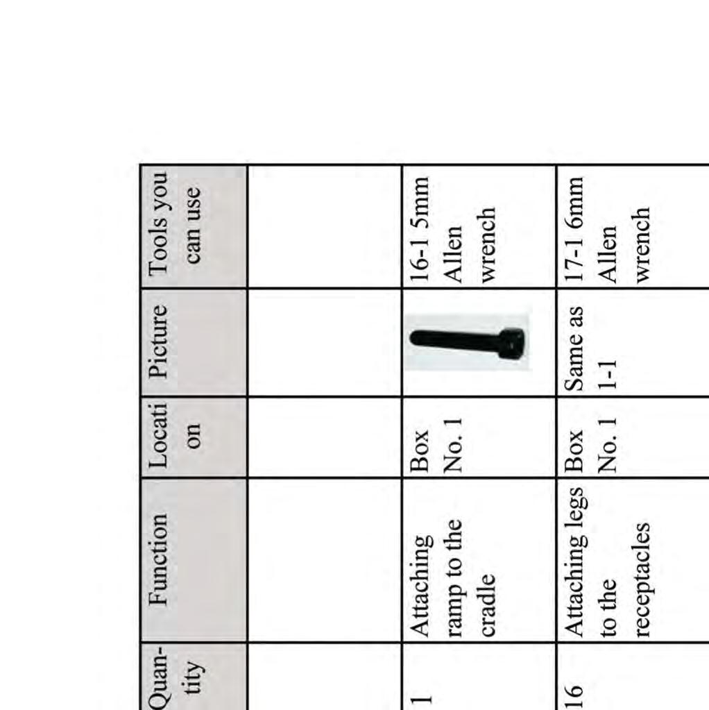
10 1-2 24mm 2 Adjusting the Open playing surface end wrench Box No. 2

11


12
13
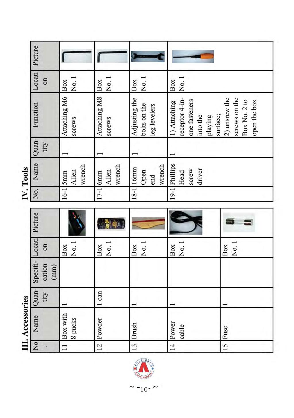
14 How to Install Parts/Screws/Bolts/Accessories/Tools List.


15 How to Install No. 6), leaving about a half inch of thread exposed to enable leveling adjustment of the table later. 2. Turn the cradle upside down on the floor and leave the back side up. Be sure to cushion the cradle with carpet or a piece of cardboard to prevent scratching the finished wood surface. 3. Screw off the two boxes near the back side of the cradle with the Phillips Screw Driver. The wire connection of the switch is illustrated in the following photo. 4. Install the 4 legs on the underside of the cradle and tighten the leg bolts. Make sure the three holes on each leg for the shelf face inside. Each leg (Part No. 6) fits into a square receptacle, and then the leg bolts (Part No. 6-1) are inserted through each side of the receptacle into the threaded insert in the legs. Snug the bolts with the Allen Wrench but do not tighten them yet. 12
 shelf (Part 8) between the other two legs with the shelf bolts (Part No. 7-1).")

16 How to Install 5. Install the front (longer) shelf (Part 7) between two of the legs by using the shelf bolts (Part No. 7-1) to attach the shelf. Install the back (shorter) shelf (Part 8) between the other two legs with the shelf bolts (Part No. 7-1). At this time, snug the bolts but do not tighten them yet. Once the shelves are installed, tighten the leg bolts with the Allen Wrench. After the leg bolts are tightened, be sure to tighten the shelf bolts with the Allen Wrench. Insert the hole plugs to hide the bolts. 6. Cover the two boxes near the back side of the cradle. And fasten them. Please make sure the cables will go through it. 13

17 How to Install 7. Now, turn the table right side up, be careful not to scratch the wood, and stand the table on its legs. 8. Open the wooden box. First take off the wrench and the screw package, and then take out the playing surface. Now you can get off the air bubble film, install the playing surface onto the cradle. The playing surface is quite heavy and it can be damaged if it is dropped down to the floor or the cradle. So be very careful with this step. Two people should carefully lift the playing surface, placing it on top of the cradle. The climatic adjusters protrude under the playing surface, and they must pass through the cut-outs in the surface of the cradle. 9. Attach the playing surface to the cradle between the two 14


18 How to Install ramps. Use 4 bolts to fasten the playing surface to the cradle from the bottom of the cradle. You will see 4 holes in the cradle, which align with 4 threaded holes in the playing surface. The attaching bolts must be placed in these holes and tightened. 10. Mount the scoreboard (Part No. 1) on the rear (small side) of the cradle. Connect the female 9-pin connector on the cradle to the male 9-pin connector on the scoreboard. Then mount the scoreboard to the cradle. Female 9-pin connector Male 9-pin connector 11. Put the small V-shaped ramp (Part No. 4) in its position and fasten the mounting screws by inserting them from the bottom of the cradle. 15
19 How to Install 12. Plug the power cable into the side of the cradle. Plug it into an electrical outlet. 13. Turn on power switch on the back side of front of the cradle. The lights in the scoreboard should now be on. When ready to play the game, stand in front of the table and reset the score to zero. The score can be reset to zero by holding down any of the red or blue score buttons for 2 seconds. The score advances by pressing the button closest to the scoreboard, and it decreases by pressing the button closest to the front of the cradle. 14. Before attempting to play, be sure to sprinkle some shuffleboard powder onto the playing surface. A light dusting, spread uniformly, should be fine. 15. You are ready to play! 16


20 How to use the climatic adjusters How to use the climatic adjusters We suggest making small adjustments, and then letting them sit for a day or two. The front adjuster: it will control the front area of the playing surface. The inside nut The outside nut To make the font part of the playing surface Convex: loosen the inside nut and then tighten the outside nut. In this way, these two nuts will move closer to the fixed nuts in other side of the rod. The nuts will move in and the playing surface will be Convex To make the front part of the playing surface Concave: loosen the outside nut and then tighten the inside nut. In this way, the nuts will move apart from the nuts in the other side of the rod. The nuts will move out and the playing surface will be Concave Use a level and sheet of paper to check the playing surface: if you can insert the paper in the middle part of the level, like the photo shows and both the outer edges of the playing surface are in contact with the level, so the playing surface is Concave. The middle adjuster: it will control the middle area of the playing surface. Please refer to the front adjuster for the adjustment.


21 How to use the climatic adjusters The back adjusters: it will control the back area of the playing surface. 1. Before you adjust the back side of the playing surface, please loosen these six nuts. The nuts are loosened 2. Adjust this part of the nuts. Please refer to the front adjuster for the adjustment. And check your adjustment 3. Adjust this part of the nuts, make sure there is no gap between the level and the V shape area of the playing surface The V shape area 4. Adjust this part of the nuts. Please refer to the front adjuster for the adjustment. And then check your adjustment This is a photo of a slight concave playing surface

22

23
Assembly Instructions
 CS-B-FM Assembly Instructions Thank you for purchasing a Shelti product. All of us at Shelti want you to be completely satisfied with your Pro Foos game, so feel free to contact us for help with the assembly
VERSA BIKE RACK INSTRUCTIONS
 VERSA BIKE RACK INSTRUCTIONS Models #8, 8 Important This rack is designed for use with a or. receiver hitch. The rack is designed to hold a maximum of two bicycles. Do not use it for anything other than
Foos 300 Assembly Instructions
 Foos 300 Assembly Instructions Thank you for purchasing a Shelti product. All of us at Shelti want you to be completely satisfied with your Foos game, so feel free to contact us for help with the assembly
8MAY15 US RACK, Inc Falcon Drive, Madera, CA
 8MAY15 US RACK, Inc. - 2850 Falcon Drive, Madera, CA 93637-559-661-3050 INSTRUCTIONS for Bedrail-mounted MOTORCYCLE RACK, Model 2001-4TRA WARNING: Do NOT attempt to install or use this rack without following
Parts: Included in the parts box: Inner Rear Tire Tray. Inner Front Tire Tray. Trail Doc Clamp. Pivot Assembly. Trail Doc Post.
 NV 2.0 2 Parts: Outer Front Tire Tray Inner Front Tire Tray Outer Rear Tire Tray Inner Rear Tire Tray Pivot Assembly Trail Doc Clamp Trail Doc Post Included in the parts box: 6mm Allen Wrench M6 Lock Washer
WEIGHT STACK ATTACHMENT. Assembly Manual (888) FOR YOUR SAFETY READ ALL INSTRUCTIONS CAREFULLY
 FOR YOUR SAFETY READ ALL INSTRUCTIONS CAREFULLY") WEIGHT STACK ATTACHMENT Assembly Manual DF835 (888) 258-0533 FOR YOUR SAFETY READ ALL INSTRUCTIONS CAREFULLY *NOTE IF YOU ARE MISSING HARDWARE OR HAVE ANY FIT UP PROBLEMS PLEASE CONTACT DELTECH FITNESS
WEIGHT STACK ATTACHMENT Assembly Manual DF835 (888) 258-0533 FOR YOUR SAFETY READ ALL INSTRUCTIONS CAREFULLY *NOTE IF YOU ARE MISSING HARDWARE OR HAVE ANY FIT UP PROBLEMS PLEASE CONTACT DELTECH FITNESS
HOME ASSEMBLY INSTRUCTIONS
 HOME ASSEMBLY INSTRUCTIONS This Papillionaire Bicycle now belongs to you. It will take you to work, wait patiently outside your local cafe, and carry your groceries home. This is the start of your long-term
INFERNO 20-IN-1 MULTI-GAME TABLE ASSEMBLY INSTRUCTIONS
 INFERNO 20-IN-1 MULTI-GAME TABLE ASSEMBLY INSTRUCTIONS NG1017M3 THANK YOU! Thank you for purchasing this product. We work around the clock and around the globe to ensure that our products maintain the
INSTALLATION INSTRUCTIONS
 KIT CONTENTS: INSTALLATION INSTRUCTIONS PART NUMBER: DESCRIPTION: E361SXA302 roof MOUNT BICycle CARRIER SINGLE Short Carriage Bolt 1x Long Carriage Bolt 3x Over-Molded Wrench 1x Button Head Screw 2x Washer
222 Schwinn Recumbent Exercise Bike Parts List Full Size Hardware Chart Product Illustration Assembly Instructions
 222 Schwinn Recumbent Exercise Bike Parts List Full Size Hardware Chart Product Illustration Assembly Instructions FITNESS SAFEGUARDS AND WARNINGS Before starting any exercise program, consult with your
Final Assembly Instructions Bikes with 16 Wheel Size
 Final Assembly Instructions Bikes with 16 Wheel Size Thank you for buying your new bicycle from L.L.Bean. Read these instructions carefully before beginning the final assembly. Prior to shipping, our expert
Assembly Instructions. -Cantilever Boat Lifts
 Assembly Instructions -Cantilever Boat Lifts Winch Instruction Page Safety Information 1. The winch is built for the multipurpose of hauling and lifting operations. It is not to be used as a hoist for
Retrofitting Green SkiErg Handles
 Materials Needed 1 replacement cord* 1 Bulldog clip Measuring tape or ruler Scissors *Contains lanolin Procedure Overview Remove the SkiErg from the wall or floor stand Remove cover plates Remove old cord
INSTALLATION INSTRUCTIONS
 INSTALLATION INSTRUCTIONS KIT CONTENTS: PART NUMBER: DESCRIPTION: E361SXA300 ROOF MOUNT BICYCLE CARRIER B9 TRIBECA Short Carriage Bolt Long Carriage Bolt 3x Over-Molded Wrench Button Head Screw 2x Washer
Konza District Pinewood Derby Track Parts And Assembly Instructions
 Konza District Pinewood Derby Track Parts And Assembly Instructions - 1 - Pinewood Derby Track Parts List: Box 1 of 3 2 each - Race Track Flat Sections 1 each - Race Track Finish Line Section 1 each -
QUALITY ALUMINUM BOAT LIFTS, INC. INSTRUCTIONS. Dominator Lake Lift
 INSTRUCTIONS Dominator Lake Lift PHONE:251-986-3882 * FAX:251-986-3136 QABLDOMINATORINST.2014 P a g e 1 Quality Aluminum Boat Lifts, INC. Installation Instructions: Dominator Lake Lift Thank you for your
A A A
 Mossberg 0 GA Talon T Rear Pistol Grip with Scorpion Recoil System A.5.0.6 A.5.0.6 A.5.0.6 Extended Scorpion Material to Reduce and Discomfort to the Shooter's Hand and Thumb Sure-Grip Texture 70.0.0 Mossberg
Model 6810A Dual Lane Scoreboard Owner s Manual Rev B
 RACEAMERICA T i m i n g S y s t e m s Model 6810A Dual Lane Scoreboard Owner s Manual Rev B RACEAMERICA, Inc. P.O. Box 3469 Santa Clara, CA 95055-3469 (408) 988-6188 http://www.raceamerica.com info@raceamerica.com
ASSEMBLY INSTRUCTIONS
 ASSEMBLY INSTRUCTIONS Ballpark Classics Baseball Game MLB Edition Figure B Read the instructions completely before beginning g assembly. You will need a Phillips screwdriver. 1. Remove the game from the
Nautique Triton Clamping Board Rack V2
 w w w.ro swe l l marine.co m Nautique Triton Clamping Board Rack V2 Installation & Usage Instructions Part # C917-180045 Information: info@roswellmarine.com If you have any questions please call : 1-21-68-11
Final Assembly Instructions Bikes with Quill Stems
 Final Assembly Instructions Bikes with Quill Stems Thank you for buying your new bicycle from L.L.Bean. Read these instructions carefully before beginning the final assembly. Prior to shipping, our expert
Installation Procedure for your Disco Double Kit, by Airgun Lab, LLC.
 Disco Double Installation Instructions Copyright Airgun Lab LLC Rev D January 2016 page 1 of 6 Installation Procedure for your Disco Double Kit, by Airgun Lab, LLC. Step 1, gather tools. Tools required
PART NUMBER: E361SXA200 DESCRIPTION: KAYAK CARRIER
 A KIT CONTENTS: : Plug 16x Long Carriage Bolt 4x Hex Key 4x Button Head Screw 4x Pad Strap BASE Over-Molded Wrench 1x SnapAround 4x 1/5 : Important Notes: Minimum crossbar spread of 24". If spread is less
Read Before Operating!
 Read Before Operating! IMPORTANT OPERATING INSTRUCTIONS THE DEUCE PITCHING MACHINE THROWS REAL REGULATION BALLS; HOWEVER, THE ACCURACY OF THE DEUCE DEPENDS ON THE QUALITY, HARDNESS AND TYPE OF BALLS YOU
FT500GF Dat e Code: 2 - FT500GF - - MW Purchase Date: PLEASE RETAIN THIS INSTRUCTION MANUAL FOR FUTURE REFERENCE. All Rights Reserved
 We strive to ensure that our products are of the highest quality and free of manufacturing defects or missing parts. However, if you have any problems with your new product, D O NOT RETURN IT TO THE STORE,
Paddle Bar Replacement
 This procedure is to help facilitate the replacement of the 23 Paddle Bar Assembly on the ANKOM Dietary Fiber Analyzer. Note: The following items will be sent in a replacement package as part of the 23
PRO1030 Bi-Directional Assembly Replacement
 PRO1030 Bi-Directional Assembly Replacement 1. Remove both side covers using the Crank and Cover Removal procedure. Fig. 1 2. Disconnect both brake cables (not shown) from the brake (S3611). (Fig. 1) 3.
Disassembling and assembling APP and APP 16-22
 MAKING MODERN LIVING POSSIBLE Instruction Disassembling and assembling APP 11-13 and APP 16-22 ro-solutions.com Table of Contents 1. Disassembling...3 2. Disassembling the pump...3 3. Assembling the pump....7
Technical Service and Warranty Manual
 Technical Service and Warranty Manual T hank you for selecting a Champion Bow. We feel confident you will be pleased with the performance and durability we build into each and every bow we manufacture.
Marine 6-Boat Free-Standing Racks SKU: Updated November 2011
 Marine 6-Boat Free-Standing Racks SKU: 30-061 Updated November 011 Contains: Marine -Boat Free-Standing Racks (SKU 1-003) Marine 3 rd Boat Expansion Racks (SKU 1-0303) Marine Back Legs (SKU -001) 3 Sets
ATOC Meteorological Tower (6 meter-4 level) Guide
 Guide") ATOC Meteorological Tower (6 meter-4 level) Guide SETUP Outline 1. Siting 2. Components 3. Transportation 4. The Tower 5. The Cables and Data Logger Siting Selecting an appropriate site for the weather
ATOC Meteorological Tower (6 meter-4 level) Guide SETUP Outline 1. Siting 2. Components 3. Transportation 4. The Tower 5. The Cables and Data Logger Siting Selecting an appropriate site for the weather
TECHNICAL DATA BROCHURE - ZTR 428 & 429
 TECHNICAL DATA BROCHURE - ZTR 428 & 429 DATE 8/89 (Rev.) MPORTANT -- READ OPERATOR S MANUAL BEFORE OPERATING OR MAKING ADJUSTMENTS. Deluxe Seat Adjustment Easy hand lever action allows forward and backward
A A A
 Winchester SXP Talon T Rear Pistol Grip with Scorpion Recoil Grip A.5.0.65 A.5.0.65 A.5.0.65 Extended Scorpion Material to Reduce and Discomfort to the Shooter's Hand and Thumb Sure-Grip Texture Triton
Gerber Sabre 404 and 408 Installation Instructions
 1 TITLE: Gerber FastFact # Supplied by: Last Modified: Summary: Gerber Sabre 404 and 408 Installation Instructions 5002 Gerber Service November 13, 2001 This document provides the installation and set-up
Stand-N-Fish FULL DETAIL INSTALLATION INSTRUCTIONS
 1 Stand-N-Fish FULL DETAIL INSTALLATION INSTRUCTIONS Thank you for purchasing the incredible new Stand-N-Fish Kayak Fishing System. Once installed on your kayak the Stand-N-Fish will take your kayak fishing
Dual Electronic Basketball System Owners Manual
 Dual Electronic Basketball System Owners Manual Customer Service Center N53 W24700 South Corporate Circle Sussex, WI 53089 U.S.A. WARNING! READ AND UNDERSTAND OPERATOR'S MANUAL BEFORE USING THIS UNIT.
Installation Guide, MPower Echelon Console
 Installation Guide, MPower Echelon Console AC Performance, AC Sport and AC Performance Plus Schwinn Echelon Console (External Routing) 1. Install batteries to console. Mount the console to the bike. 2.
Drive Belt Instructions
 Drive Belt Safety Do not roll, pry, twist, invert or bend the belt back on itself. Do not zip tie the belt. The acceptable temperature range for your belt drive is -53 C to 85 C. Do not lubricate the belt
Beach Dolly with cradle & keel pad Assembly Instructions
 Beach Dolly with cradle & keel pad Assembly Instructions H G B A D C I J L F PART NAME QTY A. AXLE... 1 with tongue bracket and cradle supports attached B. CRADLE SUPPORT BAR... 2 C. TONGUE... 1 D. TONGUE
GV Standard X-Vent. Setup, Commissioning & Installation Guide
 GV Standard X-Vent Setup, Commissioning & Installation Guide Technical experts in the design, manufacture and supply of precision engineered, architectural rooflights for residential and commercial buildings.
User Instruction Manual
 User Instruction Manual 4500 psi Air Compressor Ver 2, 1.18 Contents Parts Included...3 Assembly Instructions...3-5 Operation Instructions...6-7 Oil Change Intervals...8 Air Filter Replacement...9 Setting
DM-MARD (English) Dealer's Manual. ROAD MTB Trekking. City Touring/ Comfort Bike REAR DERAILLEUR XTR RD-M9100 RD-M9120
 Dealer's Manual. ROAD MTB Trekking. City Touring/ Comfort Bike REAR DERAILLEUR XTR RD-M9100 RD-M9120") (English) DM-MARD001-00 Dealer's Manual ROAD MTB Trekking City Touring/ Comfort Bike URBAN SPORT E-BIKE REAR DERAILLEUR XTR RD-M9100 RD-M9120 CONTENTS CONTENTS...2 IMPORTANT NOTICE...3 TO ENSURE SAFETY...4
(English) DM-MARD001-00 Dealer's Manual ROAD MTB Trekking City Touring/ Comfort Bike URBAN SPORT E-BIKE REAR DERAILLEUR XTR RD-M9100 RD-M9120 CONTENTS CONTENTS...2 IMPORTANT NOTICE...3 TO ENSURE SAFETY...4
1500 Follow Spot Yoke
 1500 Follow Spot Yoke Rev 1.1 2004 City Theatrical, Inc. Getting Started with the City Theatrical Follow Spot Yoke Congratulations on the purchase of your City Theatrical Follow Spot Yoke. The City Theatrical
Model 400ML Audible Information Device
 909 Grace St. Elgin, IL 60120 (847) 931-2455 Model 400ML Audible Information Device Congratulations you have just purchased an A.D.A. Audible Motion Detected Pedestrian Information Devise for the visually
PR4 Installation, Operation & Maintenance Instructions (DOT Certification Included)
") PR4 Installation, Operation & Maintenance Instructions (DOT Certification Included) March 2006 Form FVC 054 Rev. 6 KEEP THIS DOCUMENT WITH THE PRODUCT UNTIL IT REACHES THE END USER. The Passive - R4 device
PR4 Installation, Operation & Maintenance Instructions (DOT Certification Included) March 2006 Form FVC 054 Rev. 6 KEEP THIS DOCUMENT WITH THE PRODUCT UNTIL IT REACHES THE END USER. The Passive - R4 device
Dinghy Racers Parts List
 Parts List Thank you for your purchase of our Dinghy Racer whirligig set. Please check this list before assembly of your new Dinghy Racer set to make sure that you have all of the parts listed. 1-Yellow
Read Before Operating!
 Read Before Operating! IMPORTANT OPERATING INSTRUCTIONS THE DEUCE PITCHING MACHINE THROWS REAL REGULATION BALLS; HOWEVER, THE ACCURACY OF THE DEUCE DEPENDS ON THE QUALITY, HARDNESS AND TYPE OF BALLS YOU
Assembly Guide ST200 FUNCTIONAL TRAINER
 Assembly Guide ST200 FUNCTIONAL TRAINER Assembly Guide ST200 FUNCTIONAL TRAINER To avoid possible damage to this Functional Trainer, please follow these assembly steps in the correct order. Before proceeding,
SI-F971A. 9-speed super narrow chain such as CN-7700 / CN-HG92 8- / 7- / 6-speed narrow chain such as CN-HG50 / CN-IG51
 SERVICE INSTRUCTIONS SI-F971A Front Drive System Before use, read these instructions carefully, and follow them for correct use. WARNING Use neutral detergent to clean the chain. Do not use alkali-based
Item # in1 Rotating Table. Inch BILLIARDS AIR HOCKEY TABLE TENNIS
 Item # 45-6066 3-in1 Rotating Table 3 BILLIARDS AIR HOCKEY TABLE TENNIS 84 Inch ! WARNING: Rotating game should be done under adult supervision. Rotating table may cause a pinching hazard for young children
SERIES 2 RAMP OWNER S MANUAL TOOLS REQUIRED: BEFORE YOU BEGIN... Read and understand these instructions before beginning a ramp setup.
 SERIES 2 RAMP OWNER S MANUAL BEFORE YOU BEGIN... Read and understand these instructions before beginning a ramp setup. Use caution and care for your back when lifting, pushing, pulling, folding or unfolding
ETL listed for installations within 5 ft. (1.5M) of outer edge of water
 of outer edge of water") Color Light Streams Lighted Super Bubbler Kit Gunite CLSSBK SAVE THESE INSTRUCTIONS! SR Smith Color Light Streams Lighted Super Bubbler is a very simple device to provide lighted water for small fountains
Color Light Streams Lighted Super Bubbler Kit Gunite CLSSBK SAVE THESE INSTRUCTIONS! SR Smith Color Light Streams Lighted Super Bubbler is a very simple device to provide lighted water for small fountains
Lectric Cycles Mid-Drive Electric Motor Installation
 Lectric Cycles Mid-Drive Electric Motor Installation This write-up describes the installation of a Lectric Cycles electric motor. The model is the e-rad Mid-Drive 750 Watt conversion kit, installed on
Trike-Bike Assembly Manual
 Be sure to check our website for more instruction details, videos and photographs as well as a complete listing of each Nut and Bolt for the Trike Bike. www.trike-bike.com.au Go to the page marked ASSEMBLY
FIRST TEAM SPORTS, INC Storm Portable Series Assembly Instructions
 FIRST TEAM SPORTS, INC Storm Portable Series Assembly Instructions WARNING! WARNING! WARNING! THIS BASKETBALL SYSTEM IS SPRING LOADED AND SHIPPED UNDER TENSION. ATTEMPTING TO ASSEMBLE OR DISASSEMBLE ANY
Santa Fe Cycles Assembly Guide Introduction
 Santa Fe Cycles Assembly Guide Introduction Congratulations on your purchase of your new Santa Fe bicycle. You have purchased a bicycle that has many features and qualities. Please take a few minutes and
Final Assembly Instructions Bikes with Threaded Headsets
 Final Assembly Instructions Bikes with Threaded Headsets Thank you for buying your new bicycle from L.L.Bean. Read these instructions carefully before beginning the final assembly. Prior to shipping, our
INSTALLATION INSTRUCTIONS
 EDGEMERE CENTERSET LAVATORY FAUCET INSTALLATION INSTRUCTIONS 708.0 Thank you for selecting American Standard... the benchmark of fine quality for over 00 years. To ensure that your installation proceeds
Congratulations, once again, on buying an E RIDER Model 18!!!!
 Congratulations, once again, on buying an E RIDER Model 18!!!! USER MANUAL We are sure you will be excited by the delivery of your brand new bike and you will be eager to start using your E RIDER as soon
X-PRESS STAGE SYSTEM OWNER S MANUAL. TOOLS REQUIRED Allen Wrench (provided)
") X-PRESS STAGE SYSTEM BEFORE YOU BEGIN... Read and understand these instructions before operating. Use caution and care for your back when lifting, pushing, pulling, or folding and unfolding these units.
X-PRESS STAGE SYSTEM BEFORE YOU BEGIN... Read and understand these instructions before operating. Use caution and care for your back when lifting, pushing, pulling, or folding and unfolding these units.
TOYOTA TACOMA 2005 TOW HITCH Preparation. Part Number: PT
 Preparation Part Number: PT791 04050 Kit Contents 1 1 Hitch Center Section 2 1 LH Frame bracket 1 RH Frame Bracket 4 2 Auxiliary Bracket Hardware Bag Contents 1 6 Hex Head Bolt, M12 x 1.2 (black) 2 6 Nut,
DeskCycle USER S MANUAL. Ellipse QUESTIONS / PROBLEMS. Order# Support and Contact: See the support link at DeskCycle.com
 DeskCycle Ellipse USER S MANUAL Visit us at www.deskcycle.com for: Usage Tips Calorie Calculator Accessories And More QUESTIONS / PROBLEMS Order# Support and Contact: See the support link at DeskCycle.com
SS650 HELMET USER MANUAL
 SS650 HELMET USER MANUAL READ BEFORE USING YOUR SPEED AND STRENGTH HELMET Congratulations on the purchase of your new Speed and Strength motorcycle helmet. At Speed and Strength, we take great pride in
INSTRUCTIONS FOR THE 7FT REVOLVER 3-IN-1 MULTIGAMES TABLE
 INSTRUCTIONS FOR THE 7FT REVOLVER 3-IN-1 MULTIGAMES TABLE Please keep these instructions for future reference. Adult assembly required. This table is not a toy & is intended for use by or under the supervision
HoldUp Plus2. Safety Kit included: See additional instructions for installation. REAR WHEEL TRAY. BASE (1x) lock WASHER (1x) KEY (2x) SAFETY CLIP (1x)
 lock WASHER (1x) KEY (2x) SAFETY CLIP (1x)") HoldUp Plus2 InsTAll This product on 2" hitch version of the HoldUp Front WHEEL TRAY assembly (1x) REAR WHEEL TRAY assembly (1x) wrench (1x) BASE (1x) bolt (8X) Lock WASHER (8X) Washer (8x) KEY (2x) SAFETY
HoldUp Plus2 InsTAll This product on 2" hitch version of the HoldUp Front WHEEL TRAY assembly (1x) REAR WHEEL TRAY assembly (1x) wrench (1x) BASE (1x) bolt (8X) Lock WASHER (8X) Washer (8x) KEY (2x) SAFETY
INSTALLATION INSTRUCTIONS: SCTB1600
 INSTALLATION INSTRUCTIONS: SCTB1600 DESCRIPTION: BOLLARD, 1600 DWG: INSTALL_SCTB1600 REV: M01 BASE TYPE B1 DIRECT BURIAL - PG. 6: BOLLARD IS PERMANENT, IT IS DIRECTLY BURIED INTO CONCRETE BASE TYPE B2
Assembly, Installation, & Use Instructions
 Assembly, Installation, & Use Instructions The information in this document is subject to change without notice. Copyright Springfree Trampoline Inc. 2005, 2015. All rights reserved. 706304 WARNING Read
CamRT Sun Top Bimini Installation Instructions
 CamRT Sun Top Bimini Installation Instructions C910-07 & C910-08 Rev. 16-Jun-15 Information: info@roswellglobal.com Warranty: warranty@roswellglobal.com Questions? Please call us at (31) 638-1331 Setup:
Falcon 3 145, 170, 195 and Tandem Owner / Service Manual
 Falcon 3 145, 170, 195 and Tandem Owner / Service Manual January 2007 - Second Edition Removing The Sail From The Airframe And Short Packing The Glider Many maintenance and repair procedures will require
ORNAMENTAL CANTILEVER GATE INSTRUCTIONS
 U.S.A. Patent Number 5,36,83 ORNAMENTAL CANTILEVER GATE INSTRUCTIONS *NOTICE: Ornamental Cantilever Gates are supplied with rolls of 2 mesh safety screening in sufficient quantities to cover the entire
Installation Instructions
 Installation Instructions COLONY SOFT 7.0 Centerset Lavatory Faucet 7.0 with Speed Connect Drain Congratulations on purchasing your American Standard faucet with the Speed Connect drain, a features found
I.H.S INSTALLATION INSTRUCTIONS
 I.H.S INSTALLATION INSTRUCTIONS TOOLS REQUIRED The following tools will be required for installation of your I.H.S. system. Item Qty Needed 9/16 Open End Wrench 2 3/4 Open End Wrench 1 1/2 Open End Wrench
Installation Instructions - Steel 4 Spring Arm Kits , , , ,
 Installation Instructions - Steel Spring Arm Kits 50-0709, 50-079, 50-0750, 50-075, 50-078 GR 8// 07-00 0 N. Marshall Ave. El Cajon CA. 900 For technical support call us at (800) 8-075 Step. Determining
APP pumps APP and APP Disassembling and assembling
 Service guide APP pumps APP 11-13 and APP 16-22 Disassembling and assembling hpp.danfoss.com Table of Contents Contents 1. Introduction... 2 2. Disassembling the pump... 3 3. Assembling the pump... 6 4.
HQ Gallery2 Frame Sidearm Upgrade Kit
 HQ Gallery2 Frame Sidearm Upgrade Kit #QF12402 Assembly Instructions #QF12402-700 Table of Contents Parts List.... page 2 Step 1: Preparing the Frame for Upgrade.... page 3 Step 2: Front Sidearm Assembly
2011 RowWing ASSEMBLY INSTRUCTIONS. Congratulations on your purchase of a RowWing!
 2011 RowWing ASSEMBLY INSTRUCTIONS Congratulations on your purchase of a RowWing! STERN BOW 1. Monorail 2. Rigger Wing 3. Port Oarlock 4. Port Stern Stay 5. Stern Stay Tower 6. Piantedosi Decal 7. Port
Final Assembly Instructions Bikes with Threaded Headsets
 Final Assembly Instructions Bikes with Threaded Headsets Thank you for buying your new bicycle from L.L.Bean. Read these instructions carefully before beginning the final assembly. Prior to shipping, our
EZ-Mount 4 Spring Enclosed System to 22 (Low & High Mount Applications) Installation Instructions
 Installation Instructions") 501-1768 (With Wire) 501-1769 (No Wire) 501-1766 (With Wire) 501-1767 (No Wire) 607-015 WLH 06/20/18 TABLE OF CONTENTS ***Assembly*** ***Parts*** Pivot Points and Mounting Locations (Low Mount)... 1 High
501-1768 (With Wire) 501-1769 (No Wire) 501-1766 (With Wire) 501-1767 (No Wire) 607-015 WLH 06/20/18 TABLE OF CONTENTS ***Assembly*** ***Parts*** Pivot Points and Mounting Locations (Low Mount)... 1 High
NAVIGATOR PROP BUILDING INSTRUCTIONS & PHOTOS
 NAVIGATOR PROP BUILDING INSTRUCTIONS & PHOTOS Science under the ice Ice sheet At regional competitions the ice is simulated by 8 ft x 4 ft ½-inch foam sheeting (Home Depot part #703990 [in store only],
Installation Instructions for Tavan Models TAV-XX-XX
 Installation Instructions for Tavan Page 1 of 12 round version square version Instruction page index: Tavan stand-alone installation Tavan joiner installation Tavan L, T or X connector installation Wiring
Magnetic Bike. Model No: AENERGISER BODY WORX. Retain this owner s manual for future reference Read and follow all instructions in this owner s manual
 BODY WORX Magnetic Bike Model No: AENERGISER Retain this owner s manual for future reference Read and follow all instructions in this owner s manual Version A 1 EXPLODE DRAWING -02- PARTS LIST AND TOOLS
Chapter 9 Accessories for the Kirby Morgan BandMasks
 Chapter 9 Accessories for the Kirby Morgan BandMasks 9.1 Introduction This section provides the manufacturer s advice on how to install KMDSI accessories including the hot water shroud, low pressure inflator
Under Basin Storage Unit
 Under Basin Storage Unit Assembly Instructions- please keep for future reference ML235 Dimensions Width - 48cm Depth - 30cm Height - 60cm Important Please read these instructions fully before starting
GENUINE CARGO NET INSTALLATION AND USER S INSTRUCTIONS
 GENUINE CARGO NET INSTALLATION AND USER S INSTRUCTIONS Thank you for purchasing a genuine Mazda accessory. Before removal and installation, be sure to thoroughly read these instructions. Please read the
MUELLER. A Wall Type. Indicator Post. Reliable Connections. General Information 2. Technical Data/ Dimensions 3. Installation 4-5.
 Installation Instructions manual MUELLER table of contents PAGE A-20814 Wall Type General Information 2 Technical Data/ Dimensions Installation 4-5 Maintenance 6 Parts 7 Indicator Post! WARNING: 1. Read
INSTALLATION INSTRUCTIONS PUSH BAR PULLMAN PANIC BOLT DEVICE TO EN 1125 : 2008
 INSTALLATION INSTRUCTIONS PUSH BAR PULLMAN PANIC BOLT DEVICE TO EN 1125 : 2008 0376/448/00 ISSUE 01 EMERGENCY PUSH PAD PULLMAN BOLT DEVICE TO EN 179 : 2008 1000mm MAXIMUM CLEAR OPENING HEIGHT WITH PUSH
Sunrise Fountain Water Wonders Assembly & Mounting Instructions
 Welcome to the Water Wonders family. A few simple steps will ensure that your Sunrise Fountain remains a soothing, enjoyable fountain that brings the sights and sounds of nature to you. Two important considerations
UNITY 2. Uni-DAAMS Manual. Version 1.3 (Changes to Section 1.1) March 2010
 March 2010") UNITY 2 Uni-DAAMS Manual Version 1.3 (Changes to Section 1.1) March 2010 1. Introduction...2 1.1. Installing the DAAMS tube ovens...2 1.2. Swapping between tube types...5 1.3. Changing tube oven o-rings...6
UNITY 2 Uni-DAAMS Manual Version 1.3 (Changes to Section 1.1) March 2010 1. Introduction...2 1.1. Installing the DAAMS tube ovens...2 1.2. Swapping between tube types...5 1.3. Changing tube oven o-rings...6
4-in-1 Rotating Table
 Item # 45-6065 4-in-1 Rotating Table Air Powered Hockey, Billiards, Table Tennis, Football If you have any problems with your new product, DO NOT RETURN IT TO THE STORE! Please contact us at 1-866-815-4173,
INSTRUCTION MANUAL. January 23, 2003, Revision 0
 INSTRUCTION MANUAL Model 810A In-Vitro Test Apparatus for 310B Muscle Lever January 23, 2003, Revision 0 Copyright 2003 Aurora Scientific Inc. Aurora Scientific Inc. 360 Industrial Parkway S., Unit 4 Aurora,
42 inch Mower for TimeCutter Z Riding Mowers. Note: Determine the left and right sides of the machine from the normal operating position.
 Recycler Form No. -7 Kit inch Mower for TimeCutter Z Riding Mowers Model No. 798 Note: Determine the left and right sides of the machine from the normal operating position. Loose Parts Note: Use the chart
Bollard Light Installation Guidelines
 Bollard Light Installation Guidelines The following is provided as an overview and is not intended to be a comprehensive guide. All installations must be completed by a licensed contractor or electrician
MUELLER. A A Adjustable. Vertical Indicator Posts. Reliable Connections. General Information 2. Technical Data 3.
 Installation Instructions manual MUELLER table of contents PAGE A-20806 A-20807 Adjustable General Information 2 Technical Data 3 Dimensions 4 Installation 5-6 Parts 7 Maintenance 8 Vertical Indicator
MODEL: FIXIE / TRACK
 STEP BY STEP BUILD GUIDE MODEL: FIXIE / TRACK TABLE O F CON TENTS TOOLS 1 LET S GET STARTED 2 INSTALLING THE HANDLEBAR 3 INSTALLING THE FRONT WHEEL 4 ALIGNING THE STEM 5 INSTALLING THE SEATPOST 6 OPTIMIZING
Misaligned Folds Paper Feed Problems Double Feeds Won t Feed FLYER Won t Run iii
 Operator s Manual Table of Contents Operator Safety... 1 Introduction... 2 Unpacking and Setup... 3 Unpacking... 3 Setup... 4 FLYER Overview... 5 FLYER Diagram... 5 Capabilities... 5 Control Panel... 6
Universal Anchoring Adapter For Mercedes
 Universal Anchoring Adapter For Mercedes Anchoring Pin & Tube Set (For Most Mercedes Models) Users Manual 006 Chief Automotive Technologies, Inc. Chief s Limited One-Year Warranty & Liability CHIEF'S
M16 R / M1600 R USER S MANUAL WARNING: READ THE INSTRUCTIONS AND SAFETY PRECAUTIONS IN THIS MANUAL CAREFULLY BEFORE USING THIS FIREARM.
 ARMSCOR M16 R / M1600 R USER S MANUAL WARNING: READ THE INSTRUCTIONS AND SAFETY PRECAUTIONS IN THIS MANUAL CAREFULLY BEFORE USING THIS FIREARM. DISCHARGING FIREARMS IN POOLY VENTILATED AREAS, CLEANING
Pressure Dump Valve Service Kit for Series 3000 Units
 Instruction Sheet Pressure Dump Valve Service Kit for Series 000 Units. Overview The Nordson pressure dump valve is used to relieve hydraulic pressure instantly in Series 00, 400, 500, and 700 applicator
MUELLER A A Non-Adjustable. Vertical Indicator Posts. Reliable Connections. General Information 2. Technical Data 3.
 Installation Instructions manual MUELLER table of contents PAGE A-20808 General Information 2 Technical Data 3 Dimensions 4 A-20809 Non-Adjustable Installation 5-6 Parts 7 Maintenance 8 Vertical Indicator
Cleaning rod: spring steel, stainless steel or carbon fibre cleaning rod - only use a one-piece rod. Avoid using snakes.
 Telemark Biathlon Where performance and precision come together http://telemarkbiathlon.com Rifle Cleaning Date : July 19, 2013 Anschutz Rifle Manual - Click Here Izhmash 7-3 Rifle Manual - still looking