OWNER'S MANUAL For Models 2040, 1040, & 540 NEWGY TABLE TENNIS ROBOT IMPORTANT: READ OPERATING INSTRUCTIONS CAREFULLY QUICK SET-UP,
|
|
|
- Maud Griffith
- 6 years ago
- Views:
Transcription

1 IMPORTANT: READ OPERATING INSTRUCTIONS CAREFULLY QUICK SET-UP, QUICK SET-UP, QUICK SET-UP, OPERATION...6 ROBOT POSITIONS...12 MISC. ADJUSTMENTS...13 IMPORTANT NOTICES...15 TAKE-DOWN, ACCESSORIES...18 MAINTENANCE...20 TROUBLESHOOTING...21 EXPLODED VIEWS...24 PARTS LIST...26 WARRANTY & REPAIR..28 NEWGY INDUSTRIES, INC. P. O. BOX TEAL DRIVE GALLATIN, TN USA PHONE FAX WEB NEWGY TABLE TENNIS ROBOT OWNER'S MANUAL For Models 2040, 1040, & 540 Manufactured under one or more of the following U.S. patents: 4,844,458; 4,854,588; 4,917,380; 5,009,421; 5,335,905; 5,383,658; 5,485,995; and 6,406,386. Also covered by multiple foreign patents/patents pending. Robo-Pong, Pong-Master, Robo-Balls, and Newgy are trademarks of Newgy Industries, Inc., P. O. Box 959, 805 Teal Drive, Gallatin, TN USA. August, 2002


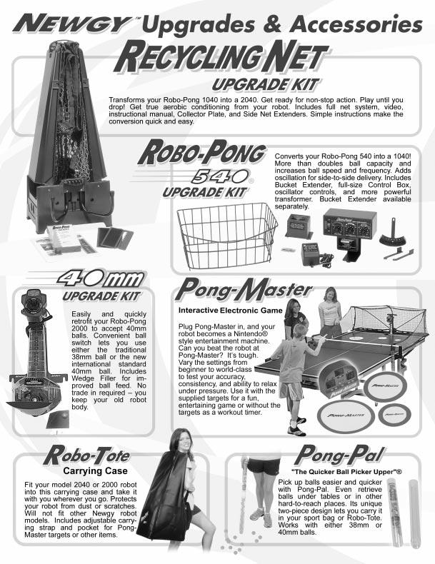
2 NEWGY TABLE TENNIS ROBOT SYSTEM The Newgy Table Tennis Robot System includes Robo- Pong models 540, 1040, and Upgrade kits are incorporated into the system to enable a customer to retain their investment in their robot and to add features and capabilities as needed. These upgrades consist of the Robo- Pong 540 Upgrade Kit to convert a 540 into a 1040 and the Recycling Net Upgrade Kit to transform a 1040 into a See page 18 for more information on these upgrades. Robo-Pong robots require no assembly or tools. They are pre-assembled and factory tested before being packed and shipped. They only require a brief set-up before they re ready for play! The following quick set-up steps will assist you in properly setting up your robot. If you purchased a 2040, a videotape is included which also explains set-up and operation. Additionally, the tape includes some simple table tennis techniques for returning the different spins your robot can deliver (also see page 8). We suggest you view the videotape first if you have a Video Cassette Recorder (VCR). For maximum enjoyment of and benefit from your Robo-Pong, it's best to follow the simple set-up steps as outlined below or as shown in the videotape. Later GENERAL INSTRUCTIONS QUICK SET-UP FOR ROBO-PONG 540 chapters of this OWNER'S MANUAL will discuss in detail robot operation, complete disassembly, maintenance, troubleshooting, accessories, parts replacement, service, and warranty. In general, instructions will apply to all models except when clearly designated by a caption, heading, or the following footnotes: 1 Robo-Pong 1040 only, 2Robo-Pong 2040 only, or 5 Robo-Pong 540 only. The ROBO-PONG PLAYER'S INSTRUCTIONAL MANUAL in your robot package (for 2040 models bought in the U.S.) explains in detail table tennis strokes, spins, serves, footwork, and other techniques. It also tells how to use your robot for fitness training and as fun entertainment for kids and adults. In addition, there is a wealth of coaching articles and other information on our website at Your robot comes with a supply of Newgy 40mm Robo-Balls (for robots bought in the U.S.). Robo-Balls are specially selected for the best robot performance possible. To order additonal balls, the instructional manual, videotape, upgrade kits, or any other robot accessory or part, please contact Newgy Customer Service. Contact info is given on the front cover of this manual. Control Box Balls (U.S. Only) Robot Body Ball Bucket Connector Cable Cable Clip Transformer VERIFY ALL PARTS 1 Unpack all the parts and check that all parts are present. If unable to identify a part, look for a small silver label with the name of the part. If any part is missing, please contact Newgy immediately. You may want to keep your box and styrofoam pieces in case you ever need to ship your robot. WASH BALLS, THEN PLACE IN BUCKET 2 Open the bag(s) of balls and wash them in lukewarm, soapy water. Then rinse in clear water and dry. Place the washed balls in the Ball Bucket. Other new balls you use should be washed and dried before placing them in the bucket. You may also include used balls with worn surfaces. All balls must be the same size (38 or 40mm). 2 VERIFY BALL SIZE SWITCHES 3 Make sure the Ball Size Switches are set to the size of the ball you are using. There are two switches, one on each side of the robot s head. If the ball is 40mm, it will have a 40 stamped on the ball; otherwise, it is a 38mm ball. If you need to adjust the Ball Size Switches, see page 10. Do not mix ball sizes. ADJUST HEAD ANGLE 4 Loosen the Brass Knob on the right side of the robot (as you re facing it), and angle the head down as far as possible and then retighten. Verify that the word topspin is at the top of the ball discharge hole. (See Figures 4, 5, & 7 on pages 7 and 8 for more info.) CONNECT CABLE TO ROBOT 5 Plug one end of the Connector Cable into the 5-Pin Connector on the back of the robot as shown. (Also see Figure 17, page 13.)
.")


3 POSITION ROBOT ON TABLE 6 Position the robot in the center of the table close to the endline as shown. The robot s head should be in line with the centerline of the table (Robot position 1, Figure 15, page 12). ATTACH CABLE CLIP TO TABLE Bring the free end of Connector Cable to 7 the player s end of the table. Remove the protective backing from the bottom of the Cable Clip. Press it onto the side of the table about 12 Cable Clip inches from the end in a horizontal position. If you re righthanded, place it on the left side of the table. If you re lefthanded, place it on the right side of the table. Open the clip and place the Connector Cable and the Transformer s cord inside the clip so approximately 12 inches of cable are free. Close the clip. Plug the Transformer into a suitable electric power source as printed on top of the Transformer. (See Chart B, page 20.) CONNECT CABLES TO CONTROL BOX 8 Plug the Connector Cable into the 5-pin socket on the rear of the Control Box. Then insert the Transformer s pin into the adjacent Power Jack (see Figure 2B, page 6). Position the Control Box at the corner of the table (See Figure 15, page 12). GET READY TO PLAY! 9 With your paddle in your playing hand, turn the Ball Speed knob to 2 3 and the Ball Frequency knob to 4 5. It takes about 30 seconds for the balls to load up before the first one is delivered. To become more familiar with the controls and adjustments for your machine, read the OPERATION section of this manual starting on page 6. QUICK SET-UP FOR ROBO-PONG 1040 Balls (U.S. Only) Bucket Extender Transformer Robot Body Ball Bucket Control Box Connector Cable ATTACH BUCKET EXTENDER Slide the Bucket 3 Extender onto the top of the bucket so that the hooks on the bottom of the Extender capture the top lip of the Bucket. Stop when the hook on the front of the Extender grabs the front lip of the Bucket. It may be necessary to lift the rear of the Locating Tab Extender over the Locating Tab protruding above the rear lip of the Bucket. Reattach the Robot Body to the Bucket by reversing step 2. VERIFY ALL PARTS 1 Unpack all the parts and check that all are present. If unable to identify a part, look for a small silver label with the part name. If any part is missing, please contact Newgy immediately. You may want to keep your box and styrofoam pieces in case you ever need to ship your robot. DETACH ROBOT BODY 2 Loosen the two Wing Nuts holding your robot body onto the Ball Bucket. Rotate the black, rectangular Clip Washers 180. Pull the Robot Body off the bucket. 3 4 FOLLOW STEPS 2 6 OF 540 SET-UP Follow Steps 2 6 of the set-up instructions for Robo-Pong 540 above and on the opposite page. SET CONTROL LEVERS TO 3 & 4 5 Verify that the Oscillator Control Levers are in the 3 & 4 positions. If not, pick up slightly on the lever and swing it or the lever guard into the correct position. More info on oscillator adjustment is on page 9.
.")
 Plug the Transformer into any suitable electric power source.")

4 CONNECT CABLES TO CONTROL BOX Bring the free end of Connector Cable 6 to the player s end of the table. Plug the Connector Cable into the 5-pin socket on the bottom of the Control Box. Then insert the Transformer s pin into the Power Jack of the Control Box (see Figure 1B, page 6). ATTACH CONTROL BOX TO TABLE 7 Place the Control Box on the side of the table about one foot from the end. If you're righthanded, place it on the left side of the table. If you're lefthanded, place it on the right side. (See Figure 15, page 12 for more detail.) Plug the Transformer into any suitable electric power source. Transformer specifications are printed on top of the Transformer. (See Chart A, page 20.) GET READY TO PLAY! 8 Turn Oscillator Speed on and when the head aligns with the centerline of the table, turn Oscillator Speed off. Pick up your paddle, turn the Ball Speed knob to 2 3 and the Ball Frequency knob to 4 5. Turn the Power switch to on and get ready to return the ball. It takes about 30 seconds for the balls to load up before the first one is delivered. When you re ready for random delivery, turn the Oscillator Speed on and the balls will be randomly delivered across the entire table. To become more familiar with the controls and adjustments for your machine, read the OPERATION section of this manual starting on page 6. QUICK SET-UP FOR ROBO-PONG 2040 Balls (U.S. Only) Rubber Tips Videotape Control Box Instructional Manual (U.S. Only) Robot Body & Net Assembly Side Net Extender Connector Cable Transformer PULL DOWN SUPPORT LEGS 2 Place the robot on the table with the open front side facing you. Pull the curved black metal support legs toward you. 3 Support Legs SPREAD SUPPORT LEGS APART Spread out the support legs to their fully open position. VERIFY ALL PARTS 1 Unpack all the parts and check that all are present. If unable to identify a part, look for a small silver label with the part name. If a part is missing, please contact Newgy. You may want to keep your box and styrofoam pieces in case you need to ship your robot. If you purchased Pong- Master, check the photo below to verify all of its parts. In your Owner s Packet is a separate OWNER S MANUAL for Pong- Master. That manual will tell you how to set up and operate Pong- Master. To help you separate robot parts from Pong-Master parts, the silver labels have RP before the part names for the robot and a PM before the part names for Pong-Master. 4 JOIN NET SUPPORT TUBES 4 Turn the robot around 180 so the Net Support Tubes are now facing you. Grasp the second tube from the right and pull up, removing it from its storage hole. Place the bottom of this tube into the top of the first tube on the right as shown. Repeat on the left side. Joining Net Support Tubes


 SET CONTROL LEVERS TO 3 & 4 9 Walk around to the rear of the robot, open the slot in the back of the net by pulling the velcro apart and verify that the Oscillator Control Levers are in the 3 & 4")
5 LOWER BALL TRAYS 5 Grasp one of the Ball Return Trays, lift straight up to unlock it, grasp the adjacent Net Support Tube, and slowly lower them into position. Be careful not to let the tray or support tube slam down. Repeat on the other side. ATTACH SIDE NETS 8 Attach a Side Net to your table tennis net by slipping the slot in the Side Net Extender over the table s net and pressing down. Be sure Side Net follows and is directly above the sideline of the table. Repeat on the other side. (See page 14 for more details.) ATTACH ROBOT TO TABLE 6 Pick up the robot by the bottom of the Center Trough and secure it to the table by angling it downward and pushing it onto the end of the table. The Support Legs go underneath the table and the Front Support Plate sits on top of the table. The center of the Front Support Plate aligns with the centerline of the table. The robot will be held by its own weight. (See Figure 10, page 9 for more detail.) SET CONTROL LEVERS TO 3 & 4 9 Walk around to the rear of the robot, open the slot in the back of the net by pulling the velcro apart and verify that the Oscillator Control Levers are in the 3 & 4 positions. If not, pick up slightly on a lever and swing the lever or lever guard into the correct position. (See page 9 for more details.) 10 FOLLOW STEPS 6 8 OF 1040 SET-UP Follow Steps 6 to 8 of the set-up instructions for Robo-Pong 1040 on the opposite page. 7 FOLLOW STEPS 2 5 OF 540 SET-UP Follow steps 2 5 of the set-up instructions for Robo-Pong 540 on page 2, except after washing the balls, place them in the robot s Ball Return Trays instead of the Ball Bucket. 5
6 Your robot is extremely versatile and fully adjustable to suit a wide variety of playing abilities and styles. Ball speed, frequency, spin, trajectory, and placement can all be adjusted, as well as oscillator speed and range. The following section will explain the various controls and adjustments of your robot. CONTROL BOX (ALL MODELS) The robot s motors are controlled electronically by the Control Box. Figures 1A and 1B illustrate the functions and controls for the 1040 & 2040 models. Figures 2A and 2B illustrate the functions and controls for the POWER Used to turn the robot ON or OFF. 2. BALL SPEED Regulates the ball speed and spin. Higher settings increase the amount of spin and forward speed on the ball. On the 540, this control also functions as the on/off switch. See also Ball Trajectory on page BALL FREQUENCY Regulates the time between shots. Lower settings increase the time between shots. OPERATION OF YOUR ROBOT Higher settings decrease time between shots. Lowest setting at which balls will come out is approximately 2 (13 to 26 balls per minute). At a setting of 10, the robot delivers approximately 90 balls per minute for the 1040 & 2040 models and 60 balls per minute for the OSCILLATOR SPEED Regulates the speed at which the robot head sweeps side to side. Higher settings make the head sweep faster. This control is also used to position the head in the desired direction when you want balls to be delivered to one spot. First set the control levers on the rear of the robot to positions 3 & 4 (see page 9). Turn Oscillator Speed on, and when the head reaches the desired position, turn it off. See also Figures 3A & 3B below. WARNING: Use the Oscillator Speed control to make the robot head move sideways. DO NOT attempt to move the robot head sideways by hand. Doing so will likely result in broken parts and may void your warranty. If you open Control Box, remove ONLY these 4 screws Pin of Transformer plugs in here Connector Cable from robot plugs in here FIGURE 1A CONTROL BOX FOR 1040/2040 TOP VIEW FIGURE 1B Linking Cable from Pong-Master Scoreboard (optional) plugs in here CONTROL BOX FOR 1040/2040 BOTTOM VIEW Connector Cable from robot plugs in here Pin of Transformer plugs in here FIGURE 2A CONTROL BOX FOR 540 TOP VIEW FIGURE 2B CONTROL BOX FOR 540 REAR VIEW FIGURE 3A INCORRECT OSCILLATOR SPEED (1040/2040 ONLY) Because oscillator speed has not been set correctly, the second ball is placed too closely to the first ball. This results in not having to move the feet very much. FIGURE 3B CORRECT OSCILLATOR SPEED (1040/2040 ONLY) 2 1 Oscillator speed has been adjusted so the second ball lands well away from the first ball. This makes the player move the feet a greater distance, resulting in better footwork and more exercise
7 BALL TRAJECTORY (ALL MODELS) The trajectory of a ball is regulated by adjusting the angle of the robot head. The angle can be changed from low to high. At its lowest setting, the ball will be delivered so it first strikes the robot's side of the table, bounces over the net, and lands on the player's side of the table (just like a serve). At its highest setting, the ball will be delivered in a high arc over the net (like a lob return). The trajectory is adjusted by loosening the Brass Knob on the right side of the robot head, tilting the head to the desired angle and then re-tightening the Brass Knob (see Figure 4). For reference, there are head angle indicators next to the Brass Knob (see Figure 5). WARNING: DO NOT adjust the head angle when the head is moving side to side. Failure to follow these instructions will likely result in broken parts and may void your warranty. The ball trajectory setting is directly related to the Ball Speed setting. When the head is set so the ball first strikes the robot's side of the table (robot serving see Figures 6C & 6D), maximum Ball Speed is 3 5. As the Ball Speed is turned up, the head must be angled up to deliver the ball so it first strikes the player's side of the table (robot returning see Figures 6A & 6B). As the Ball Speed is turned up even more, adjust the head angle down to prevent the ball from being thrown off the end of the table. 70 Angle Pointer } Loosen Brass Knob Head Angle (66) To Adjust Angle Indicators Of Head Up Or Down. DO NOT FORCE! 66 Brass Knob FIGURE 4 ADJUSTING HEAD ANGLE FIGURE 5 HEAD ANGLE INDICATORS Robot Head FIGURE 6A INCORRECT ROBOT HEAD ANGLE, ROBOT RETURNING Robot head is tilted too high, resulting in ball being thrown off the end of the table. Robot Head FIGURE 6B Robot Head FIGURE 6C Robot Head FIGURE 6D CORRECT ROBOT HEAD ANGLE, ROBOT RETURNING INCORRECT ROBOT HEAD ANGLE, ROBOT SERVING CORRECT ROBOT HEAD ANGLE, ROBOT SERVING 7 Same ball speed as Figure 6A, but now robot head is tilted down so the ball lands on the table. When robot is set to serve onto its side of table first, and the head angle is too severe, the ball will rebound abnormally high. Same ball speed as Figure 6C, but head angle has been raised slightly so ball stays low to the net. With robot serving, maximum ball speed is limited to 3 5 before ball is thrown off the end of table.
8 BALL SPIN (ALL MODELS) Robo-Pong robots are capable of putting any type of spin on the ball. Topspin, backspin, sidespin, and even combination spins can easily be selected. To change the spin, simply rotate the head of the robot until the desired spin is at the top of the Ball Discharge Hole (see Figure 7). For combination spins, move the head until one of the rotational arrows is at the top of the Ball Discharge Hole. For instance, if the arrow between Topspin and Sidespin is selected, the robot will deliver a ball containing both topspin and sidespin. Likewise, if the arrow between Backspin and Sidespin is selected, the robot will deliver a combination backspin/sidespin ball. Before discussing how to return spins, it's important to know that your robot simulates the play of a modern table tennis professional using inverted sponge rubber. With Robo-Pong robots, there is always some kind of spin on the ball. To learn how to produce your own spin and return an opponent s (or the robot s) spin, it is important to use the correct equipment a quality inverted or pips out sponge rubber racket. Using old-style paddles such as hard rubber or sandpaper will make it more difficult to control spin. Each spin has a different effect on the ball and how the ball reacts when you strike it with your paddle. Following are some brief pointers to help you return the different spins. More detail is available in Chapter 7 of the PLAYER'S INSTRUCTIONAL MANUAL which is included with your Robo- Pong 2040 if bought in the U.S., or available separately. The secret to returning spin is to angle your paddle correctly when contacting the ball. Any spin can easily be returned if you angle your paddle properly. Set your paddle angle at the beginning of your stroke and maintain the same angle until your stroke ends. Avoid changing your paddle angle during your stroke. (See Figure 8.) Topspin causes the ball to dip downward as it travels through the air. When you strike the ball with your paddle, it has a tendency to pop up high in the air. To compensate for topspin, angle your paddle face down as you stroke through the ball in a forward and upward direction. Contact the top surface of the ball. (See Figure 8A.) Backspin causes the ball to rise upward and float as it travels through the air. When you strike the ball with your paddle, it has a tendency to go straight down into the table. To compensate for backspin, angle your paddle face upward as you push your paddle straight forward. Contact the bottom surface of the ball. (See Figure 8B.) Sidespin makes the ball curve sideways through the air. Left sidespin makes the ball rebound off your paddle to your right; right sidespin to the left. To compensate for left sidespin, angle the paddle face to the left and contact the right side of the ball. To compensate for right sidespin, angle your paddle face to the right and contact the left surface of the ball. (See Figures 8C &8D.) Combination spins take on the characteristics of both spins, although to a lesser degree than the pure spins. To compensate for topspin/right sidespin, you must angle your paddle face down and to the right and contact the top left surface of the ball. Likewise, a backspin/left sidespin ball is best returned by angling your paddle face up and to the left and contacting the ball on its bottom right surface. Spins are increased by turning up the Ball Speed knob on the Control Box. You increase both the speed and spin on the ball every time you turn up the Ball Speed knob. It is not possible to adjust Robo-Pong robots to deliver a slow ball with lots of spin, for instance. It is also impossible for Robo-Pong robots to deliver a no-spin ball. Additionally, since backspin causes the ball to rise, the maximum setting for Ball Speed when the robot is set on Backspin is approximately 4 5. Rotate Head So Desired Spin Is Listed In Upright Position CAUTION: Do Not Twist Power Cord Around Head. Rotate No More Than 180 In Either Direction From Position Shown A RETURN SHOT TOPSPIN SIDE VIEW RETURN SHOT PADDLE B RETURN SHOT BACKSPIN SIDE VIEW RETURN SHOT PADDLE FIGURE 7 SPIN SELECTION 8 C PADDLE LEFT SIDESPIN TOP VIEW FIGURE 8 D PADDLE RIGHT SIDESPIN TOP VIEW PADDLE ANGLE ADJUSTMENTS FOR VARIOUS SPINS

. Models 1040 and 2040 have 8 selectable ranges (or zones) in which the robot head will sweep, delivering balls randomly within that zone.")
9 OSCILLATION RANGE (1040/2040 ONLY) Oscillation is the sweeping motion of the robot s head, enabling the robot to deliver consecutive balls to different spots on the table. Since Robo-Pong 540 has no oscillation controls, the information on this page does not apply to the 540. Furthermore, the oscillator ranges given on this page will apply to the 1040 and 2040 only when these models are positioned so the robot head is aligned with the centerline of the table (Position 1 or 5, Figure 15, page 12). Models 1040 and 2040 have 8 selectable ranges (or zones) in which the robot head will sweep, delivering balls randomly within that zone. These zones are regulated by the Control Levers at the back of the robot (see Figure 9). Ranges are identified on a label at the top of the robot (see Figure 10). Figure 10A further clarifies these ranges. Zones are selected by moving a Control Lever into the desired position as indicated by the number that appears through the hole in the Control Lever (see Figure 9). The Right Control Lever is restricted to positions 1, 2, & 3; the left to positions 4, 5, & 6. (Left and right designations for the robot are given as if you are facing the robot.) To move a lever, lift it up with your finger, move it to the desired position, and then release it. If the lever will not move easily, pick up the lever and move the Control Lever Adapter instead. To access the Control Levers on the 2040, open the slot in the back of the net by pulling the velcro apart and reach with your fingers through the slot to touch the Control Levers (see Step 9 on page 5). WARNING: DO NOT adjust the Control Levers while the head is moving. Also do not move both levers at the same time. Move one, then the other. Failure to follow these instructions will likely result in broken parts and may void your warranty. Following is an explanation of each zone that can be selected as shown in Figures 10 and 10A: 3,4 Robot delivers balls across the entire table, from corner to corner (whole table). 3,5 Robot delivers balls from player s left corner to middle of right court ( 3 /4 table). 2,4 Robot delivers balls from player s right corner to middle of left court ( 3 /4 table). 1,4 Robot delivers balls from player s right corner to centerline. ( 1 /2 table). 3,6 Robot delivers balls from player s left corner to centerline ( 1 /2 table). 2,5 Robot delivers balls from middle of player s right court to middle of left court ( 1 /2 table). 1,5 Robot delivers balls from middle of player s right court to centerline ( 1 /4 table). 2,6 Robot delivers balls from middle of player s left court to centerline ( 1 /4 table). 1,6 No oscillation. Place Control Levers in these positions whenever you transport or ship your robot, to prevent damage to the oscillator mechanism. If you want stationary delivery, adjust the Control Levers to 3,4 and turn oscillator speed on. When the robot head points to the desired landing spot on the table, turn Oscillator Speed off. Failure to set the levers to 3,4 may result in head drift, which causes the landing spot to change even though the oscillator is turned off. 82 Control Lever, R FIGURE 9 FIGURE 10 SWEEP CONTROL ADJUSTMENT OSCILLATOR CONTROL LEVERS TOP VIEW (1040/2040 ONLY) SWEEP CONTROL ADJUSTMENT CAUTION: Do Not Move Robot Head By Hand; Use Oscillator Speed Knob On Control Box Numbered Oscillator Positions 80 Control Lever Adapter 81 Control Lever, L SWEEP ADJUSTMENT LABEL (1040/2040 ONLY) FIGURE 10A OSCILLATOR RANGES OF ROBOT WITH CONTROL LEVERS IN VARIOUS POSITIONS AND ROBOT ALIGNED WITH CENTERLINE OF TABLE (1040/2040 ONLY) 9


10 BALL SIZE SWITCHES (ALL MODELS) In October, 2000, the International Table Tennis Federation (ITTF) changed the size of the ball used in sanctioned tournaments from 38mm to 40mm in diameter. The traditional 38mm ball has been used since the early 1900 s and is still readily available in many countries, including the U.S.. The ITTF requires that all 40mm balls be stamped with a 40 or 40mm so they can be readily distinguished from 38mm balls. If you bought your robot in the U.S., it came with a supply of 40mm balls. Robo-Pong models 540, 1040, and 2040 are all capable of using either the 38mm or 40mm ball. You must tell the robot what size ball you are using by setting the Ball Size Switches located on the robot s head. There is a switch on both sides of the head and it is extremely important that both switches be set correctly. Steps 1 and 2 below show how to set the switches and Steps 3 to 9 show what to do when changing from one ball size to the other. 1 SETTING SWITCH FOR 38MM BALLS To set the switches for 38mm balls, hold the head steady with one hand while pulling the switch forward with your other hand until the switch snaps into the 38 position. Repeat on the other side of the head. SETTING SWITCH FOR 40MM BALLS 2 To set the switches for 40mm balls, turn power off and rotate the robot head so that Topspin is at the top of the discharge hole. Insert your thumb into the hole and press down on the rubber Friction Block just inside the opening. With your other hand, press the Ball Size Switch backward to 40 while continuing to depress the Friction Block. Repeat on the other side. WARNING: DO NOT use undue force to move the switch to the 40 position. The Friction Block MUST be depressed before the switch can be moved easily. 3 REMOVE BALLS FROM TRAY OR BUCKET The following steps are necessary whenever changing from one ball size to the other. First, remove all balls from the Bucket (540 or 1040) or Trays (2040) and place them in a box where they will not get mixed in with balls of the other size. Then disconnect the Connector Cable from the back of the robot. 10 LOOSEN WING NUTS 4 Loosen the two Wing Nuts that hold your robot body onto the Ball Bucket or Center Trough. Rotate the black, rectangular Clip Washers 180. Clip Washer 5 REMOVE ROBOT BODY Pull straight up on the robot body to remove it from the Ball Bucket or Center Trough. 6 REMOVE CLEAR FRONT COVER Place the robot body on your table. Pull the Clear Front Cover off by squeezing on the circular fingerholds on the sides of the cover with your thumb and forefinger, and then pulling up while squeezing. Pull the cover loose first at the top and then at the bottom. (See also Figure 23, page 15.) 7 REMOVE BALLS FROM INSIDE ROBOT Remove all balls from inside the robot and place in the box with the other balls of the same size. Also gather up any balls that are on the floor or lying around loose in the playing area and place them inside the box too. 8 REATTACH ROBOT BODY Reattach the Clear Front Cover (reverse of Step 6). Reattach the robot body, making sure that it fits fully down on the locating tab of the Center Trough or Ball Bucket. (See Figure 17, page 13.) Finally, re-tighten the Wing Nuts (reverse of Step 4). FINAL PROCEDURES 9 Place balls of the other size in the Ball Bucket or Ball Trays. (Be sure to wash and dry new balls before using them for the first time.) Select the proper setting for both Ball Size Switches (see Step 1 or 2, depending on ball size being used). Reconnect the Connector Cable (see Figure 17, page 13). Turn power back on and you re ready to play.


 BALL DAMS (2040 ONLY) Robo-Pong 2040 comes with a pair of")
11 WARNINGS 1. You must use all 38mm balls or all 40mm balls at one time. Do not mix ball sizes. 2. Be sure BOTH switches are set to the same size. 3. When swapping out ball sizes, remove all balls from the robot, including the ones inside the machine and those lying around the playing area, before re-loading the other-sized balls. 4. Immediately after adjusting the switch, depress and then release the Friction Block 2 3 times so it re-seats itself properly. 5. Be sure to wash and dry new balls before using them with the robot. New balls can cause multiple problems until they become slick. (See Note 4, page 15.) 6. When switched to "40", if a 38mm ball gets mixed in with the 40mm balls, the 38mm ball will be ejected with very little forward speed. 7. When switched to "38", if a 40mm ball gets mixed in with the 38mm balls, the 40mm ball will either jam inside the robot's head or be ejected with an irregular trajectory. Damage may result. 1 Center Trough FIGURE Ball Dam Ball Dam Storage Slot Ball Dam Retainer Slot Ball Checker Holes BALL DAM & CENTER TROUGH (2040 ONLY) BALL DAMS (2040 ONLY) Robo-Pong 2040 comes with a pair of Ball Dams. They serve three functions: (1) they keep balls inside the Center Trough when the robot is folded up, (2) they keep balls from entering the Center Trough when you want to remove the robot body, and (3) they serve as a ball gauge for determining if a ball is the proper size and whether it should be used in the robot. The Ball Dams, when used for functions 1 or 2, fit into two retaining slots at the top of the Center Trough. When not in use, the Ball Dams fit into their storage slots on the side of the Center Trough (see Figure 11). To use the Ball Dams when preparing the robot for storage or transport, remove the Ball Dams from their storage slots by pulling slightly up on the trays to reveal the storage slots (see Figure 13). Then push all the balls into the Center Trough and insert the Ball Dams into their retaining slots (see Figure 12). To use the Ball Dams for function #2, push the balls up into one of the Ball Return Trays and quickly insert the Ball Dam into its retaining slot before the balls can roll down into the Center Trough. The balls will be out of the way and you can easily loosen the two wing nuts and two clip washers, then pull up on the robot body to remove it (see Steps 4 & 5, opposite page). The holes in a Ball Dam serve as a handy ball checking feature. One hole is 40mm in diameter and the other one is 38mm. The holes are marked with a 38 or 40 accordingly. These holes are used to test the roundness and size of balls you use in the robot. If you suspect a ball is out of round or too large, as indicated by balls jamming within the robot, insert the suspected ball into the ball checker hole. With your fingers, rotate it around inside the hole to check all possible diameters of the ball. The ball should have equal clearance through the hole on all diameters. The ball should barely fit through the hole without binding. It is also possible that a ball is too small. In this case, you will notice a considerable gap between the ball and the edge of the hole. 11 FIGURE 12 FIGURE 13 FIGURE 14 INSERTING BALL DAM (2040 ONLY) REMOVING BALL DAM (2040 ONLY) Rotate Ball Inside Hole To Check All Diameters Of The Ball. Ball Should Pass Easily Through Hole On All Diameters. CHECKING BALL WITH BALL DAM (2040 ONLY)
12 POSITIONING YOUR ROBOT AND CONTROLS (ALL MODELS) Robo-Pong robots are versatile in how they are positioned in relation to the table. The 540 and 1040 normally sit on top of the table as shown in robot positions 1 4 in Figure 15. They can also be mounted in the optional Robo-Caddy (see page 19) and placed behind the table like positions 5 & 6. The 2040 is typically mounted to the end of the table at position 5, but can alternatively be mounted in the Robo- Caddy just like the 540 and Some positions offer certain advantages while other positions compromise some of the robot s functions. By placing the robot in various positions you can achieve a variety of angles and trajectories to simulate almost any type of shot you would encounter in a regular game. The following paragraphs explain this further. Position 1 Robot positioned square to the table where the centerline and endline of the table meet. This is the only on the table position in which the 1040 s oscillator ranges will be accurate (see OSCILLATION RANGE, page 9). Also this is the desired starting position when first setting up either the 540 or the In this position, the 540 will shoot straight down the centerline of the table. Position 2 Robot positioned at the far left corner and angled cross-court. This position will skew the 1040 s oscillator range toward the player s right side of the table. The 540 in this position would deliver the ball towards the player s right corner. This position would be the preferred direction when simulating typical right-handers forehand to forehand rallies. Position 3 Robot positioned at the far right corner and angled cross-court. Setting the robot in this position will skew the 1040 s oscillator range toward the player s left side of the table. A 540 placed in this position would direct its shots to the player s left corner. Typical backhand to backhand play for right-handers would be ideally simulated with the robot in this position. Position 4 A robot placed in this position has the advantage of offering slower and faster ball speeds because it is closer to the landing spot of the ball. At a Ball Speed setting of 0, the ball is very slow and with light spin, but is delivered deep on the player s end. At a Ball Speed setting of 10, the ball speed is very fast and simulates the angle from which a typical kill shot would be hit. However, the 1040 s oscillator ranges are narrower than if the robot had been positioned at the endline like Positions 1 3. Position 5 This is the normal position of the 2040 when it is attached to the end of the table, and its net system would function normally. The 1040 and 540 would have to be mounted in the Robo-Caddy to be in this position. Positioned here, the 2040 s and 1040 s oscillator ranges would be accurate. Position 6 Mounted in a Robo-Caddy, all three models can be freely moved around in back of the table. The Robo-Caddy also permits lowering or raising the height of the robot. This is great for simulating deep shots such as chops, lobs and loops. However, the oscillator ranges for the 1040 and 2040 are not accurate and the 2040 s net system is usually not effective at capturing balls when in this position. Additionally, you need to purchase 12 a Connector Extension Cable (part# ) to extend the length of the Connector Cable from 10 to 20 feet. This permits the Control Box to stay within reach of the player. These positions are only a few of the ones possible, but they will give you a good idea of the pluses and minuses of placing the robot in a particular position. IMPORTANT NOTE: Even though the oscillator ranges may not be accurate as described on page 9 when the robot is in certain positions, you should be able, with experimentation, to find the correct settings for the Control Levers to permit ball delivery over any particular part of the table. Figure 15 also illustrates the ideal positions for the Control Box. If you re right-handed, Position A is the preferred location for the controls. If you re left-handed, Position B is preferred. Locating the controls in these suggested positions permits the controls to stay within easy reach of the player s free hand. Since a player has a longer reach on the forehand side, it is suggested that you position your body as shown. The overwhelming majority of tournament level players use their backhand to cover about one-third of the table and their forehand to cover the other two-thirds of the table. FIGURE 15 Robot 6 Robot 2 Right Hand Player Robot 5 Robot 1 Robot 3 Robot /2040 Control Box 540 Control Box A A B B Left Hand Player ROBOT AND CONTROL BOX POSITIONS
13 MISCELLANEOUS ADJUSTMENTS (2040 ONLY) LEVELING ADJUSTMENT (2040 ONLY) Robo-Pong 2040 is designed to sit level when attached to the table. In proper position (Figure 16), the CT Support Legs fit underneath the table and the CT Front Support Plate sits on top of the table. If the robot does not sit level, balls will not feed properly. If this condition occurs, it is necessary to make some leveling adjustments. The first adjustment is to level the table top by placing shims under the table legs until the table top is level. If this does not cause the robot to sit level, then it will be necessary to make adjustments to the robot itself. The Support Legs come with 3 sizes of Rubber Tips and 4 rubber spacer-washers to accommodate different table top thicknesses, and cause the Center Trough to sit level. The Rubber Tips are marked on their top with the table thickness they are used with. The longest is used for 1 /2 tops. The mid-size one is used on 3 /4 tops and comes preinstalled. The shortest tip is used for 1 tops. In addition to these different sized tips, there are 4 rubber spacer-washers which are used with the Rubber Tips for finer adjustments. Either one or two of these spacer-washers (depending on how much adjustment you need) are placed inside the Rubber Tips before the tips are placed on the end of the Support Legs. Another reason why your robot may not sit level is that it is not properly seated on the locating tab. When seated correctly, the Support Flange of the Back Panel sits flush on the Locating Tab that protrudes from the top of the Center Trough (see Figure 17). Your robot serial number is located on top of this Support Flange. Tip: If it is possible to adjust the level of the robot s half of the table independently from the player s half, you may choose to purposely give a slight slope to the robot s half so balls that end up on the table roll into the robot s trays. If you make the table unlevel, make sure the robot sits level by adjusting the Rubber Tips as described above. In this case, it may be necessary to use the Rubber Tip one size larger than normal to level the robot. Table Tennis Table 10,11,12 CT Support Leg Rubber Tip Come In 3 Sizes So Center Trough Will Sit Level. FIGURE 16 Serial # Located Here FIGURE 17 5 CT Front Support Plate 8,9 CT Support Legs Robot CENTER TROUGH ATTACHMENT (2040 ONLY) Support Flange Of Robot Sits Fully Down On Locating Tab Of Center Trough 32 Wing Nut 1 Center Trough (Should Be Level) Back Of Robot 15 Ball Dam In Storage Position To Control Box 94 Connector Cable SUPPORT FLANGE ALIGNMENT & SERIAL # (2040 ONLY) ADJUSTING NET TENSION (2040 ONLY) The Ball Return Trays should sit level with or just below the level of your table top. If the tension of the Main Net is too tight, the trays will be pulled up into a slight V shape with the top edge of the trays above the level of the table top. To correct this situation, you can loosen the adjustment straps shown in Figure 18 until the trays sit level. If this adjustment is insufficient, stretch the net by grabbing it with two hands and pull gently apart. The Trap Net (the black net with large holes) slows down your returns so more of them are captured. The size of the holes is slightly smaller than the diameter of a ball. Hard hit shots force the ball through the net and the ball becomes trapped between the Trap Net and the Main Net. When slowly hit balls contact the Trap Net, they do not have enough force to go through the net, so they immediately drop down into the trays. The Trap Net is normally hung loosely so as to increase its energy-absorbing capability. If you are practicing hard 13 Velcro Straps FIGURE 18 FIGURE 19 ADJUSTING MAIN NET TENSION (2040 ONLY) Velcro Straps ADJUSTING TRAP NET TENSION (2040 ONLY)
.")


14 hit shots like smashes or fast loops, you may find that a tighter Trap Net captures more of your shots. The tension of the Trap Net is adjusted by tightening or loosening the velcro straps at the sides of the Trap Net (see Figure 19). Attach the Side Nets to the table s net by slipping the slot in the Side Net Extender over the table net and press down until it stops (see Figure 20A). Remove the Extender by pressing the Extender forward with one hand while simultaneously pressing the table net backward with your other hand. Make sure that the entire height of the table net is pressed against the smooth edge of the Extender s slot (see Figure 20B). Otherwise, the toothed edge of the slot will grab the net and make removal more difficult. Side Net Extenders come in pairs and mate with the Velcro Straps sewn to the ends of the Side Nets. The Extenders are not interchangable due to how the Velcro is fastened to the Extender. One Extender will mate correctly to the Velcro sewn to the end of the right Side Net and the other Extender will mate correctly to the left Side Net. By adjusting how a Side Net attaches to a Side Net Extender, you can tighten or loosen a Side Net. When properly tensioned and positioned, the Side Nets should slightly pull the table net to produce enough tension that the Side Net remains upright with little net sag. The Side Net should hang directly above the sideline of the table with very little or no gap between the bottom of the Side Net and the table surface (as shown in Figure 22B). Figure 21 shows how to adjust Side Net Tension: 21A This is the loosest setting. The Side Net s velcro is fastened to the first half inch of the Extender s velcro. 21B This setting pulls the Side Net forward approximately 2 inches from the 21A setting. The front edge of the Side Net s velcro is even or slightly forward of the smooth edge of the Extender s slot. 21C This setting pulls the net forward about 2 inches from the 21B setting. The Extenders have been switched so the left Extender is used on the right and right Extender is used on the left. The Side Net s velcro has been turned 180 so that what was the back edge is now the front edge. 21D This setting is almost the same as 21C, but instead of the net being on the outside of the velcro, it has been turned inward so it is captured between the Side Net s velcro and the Extender s velcro. This setting pulls the net forward another 1 /2 or so from the 21C setting. 21B, C, and D represent the tightest settings possible with the Side Net s velcro in a certain position. Of course, you may loosen the net from any of these three positions by moving the Side Net further back on the Extender. When first used, the netting material is taut. The material will relax over time by itself. If the net adjustments given in Figure 21 do not fix a problem, it may be necessary to manually relax the net. Figure 22A illustrates this problem. Even though the length of the Side Net has been adjusted correctly, the bottom of the Side Net is too high, allowing a ball to roll underneath it. To correct, gently stretch the netting material directly above the problem area until it relaxes enough to where the bottom edge of the net is just above the table surface (see Figure 22B). A FIGURE 20 A L O O S E C T I G H T E R FIGURE 21 A FIGURE 22 B B D ATTACHING AND DETACHING THE SIDE NET (2040 ONLY) T I G H T T I G H T E S T ADJUSTING SIDE NET TENSION (2040 ONLY) B IMPROPER/PROPER GAP FOR SIDE NET (2040 ONLY) 14
15 IMPORTANT NOTICES (ALL MODELS) WARNING: These points are vital for proper use and care. Failure to heed these points may cause damage to the robot. 1. Robo-Pong 2040, 1040, and 540 robots can use either the traditional 38mm ball or the newer 40mm ball. You must change BOTH Ball Size Switches on the robot s head to match the size of the ball you are using. Do not mix ball sizes. (See BALL SIZE SWITCHES, page 10 for more info.) 2. Before connecting your robot to power, be sure the transformer matches the power source in your area. Transformer specifications are printed on top of the transformer. (See Chart A or B on page 20.) and 1040 robots are equipped with a special safety feature to warn you when ball jams occur. Your Control Box emits a high-pitched squealing noise and shuts off the ball feed when it detects a ball jam! Don t worry your machine is operating the way it was designed to. This shut-off feature prevents damage to the ball feed gears and motor. Normally the solution is very simple. Turn off your Control Box, then agitate the balls where they feed into the machine. In particular, look for balls that have become stuck around the Ball Feed pickup mechanism. If agitating the balls doesn t fix the problem, then the problem is inside the robot. To inspect inside the robot, remove the balls from the Bucket or the Trays and then remove the robot body by following Steps 3 to 6 on page 10. After removing the Clear Front Cover (see Figure 23), look for balls that are cracked, dented, too large, or out-of-round. To test for ball roundness and correct size, read the last paragraph on page 11 and refer to Figure 14. Discard any bad balls. 4. Many ball jams are caused by new balls. Before using new balls, including the ones that came with your robot (if applicable), be sure to wash them in lukewarm, soapy water. After washing, dry all balls with a clean, dry cloth before putting them in the Ball Bucket 1,5 or Ball Trays 2. This will remove the powder that is on the surface of the balls. This powder causes excess friction, making the robot run erratically until the powder is removed. After putting them in the Ball Bucket or Ball Trays, run the balls through the machine at high frequency by setting the Ball Frequency to 10, the Ball Speed to 3, the spin to backspin, and aim the head at the middle of the table net. The balls will hit the table net, rebound, and automatically return into the net system (for robots with net systems). For robots mounted in Ball Buckets, catch these balls by hand or in a tray or box, and return them to the Ball Bucket. This procedure will further rub the balls down. Continue this rub down procedure for at least 5 minutes, then return to normal operation. 5. Use 3-Star balls or Newgy Robo-Balls for best performance. Most other brands of approved 1-Star, 2-Star, or 3-Star balls will also work. Avoid inexpensive Remove Clear Front Cover By Squeezing Fingerholds Next To The Locking Tabs. Loosen Top First, Then Bottom. FIGURE 23 Locking Tabs On Front Cover Snap Into Slots On Back Panel 40 Collector Plate (2040 Only) REMOVING CLEAR FRONT COVER ungraded and unapproved balls, especially those with rough seams. Well worn balls work best. 6. When moving the 2040, always support it under the Center Trough. Do not carry it by the Tray Strap. The strap may loosen, causing you to drop your robot. If you want to carry it by the strap, replace the Rubber Strap with our optional Carrying Strap (see page 19). 7. Store unit indoors only. Do not leave the robot or Control Box outdoors. Avoid leaving unit in a hot car or trunk. Plastic parts can warp, crack, or melt if exposed to extreme temperatures. Do not use robot around sand. Sand will abrade plastic surfaces. 8. When lowering the trays on the 2040, don t let the trays fall down into place. Lower them gently. (See Step 5, page 5.) 9. Do not use sandpaper paddles with your robot. Sand can loosen from the paddle and end up inside the robot where it can cause numerous problems. 15


16 TAKE DOWN, STORAGE, & TRANSPORT (2040 ONLY) Robo-Pong 2040 can be easily taken down in less than 5 minutes. Your robot folds very compactly with all parts inside the robot. This model is also lightweight and very portable. Follow these steps to be sure all parts fold up correctly. PLACE SIDE NETS IN TRAYS 1 First, unplug the Connector Cable from the back of the robot. Then detach the Side Nets and place them in the trays. PLACE CORDS IN CENTER TROUGH 5 Unplug the Transformer and Connector Cable from the Control Box and unplug the Transformer from the wall outlet. Coil both cords and place on top of the balls in the Center Trough. Place the Side Net Extenders on top of the balls. If you have Pong- Master, you may place its scoreboard and all of its cords on top of the balls as well. PLACE ROBOT ON CORNER OF TABLE 2 Remove the robot from the table and set it down on the corner of the table so you can easily access both the front and back of the robot. REMOVE BALL DAMS 3 From the front of the robot, raise each tray slightly and remove the Ball Dams from their storage positions. Don t raise too much or the balls will fall out! (See Figures 11 & 13 on page 11 for more detail.) INSERT BALL DAMS 4 Push the balls into the Center Trough and place the Ball Dams in their retaining slots. (See Figures 11 & 12 on page 11 for more detail.) Removing Ball Dam From Storage Slot ADJUST HEAD ANGLE 6 Loosen the Brass Knob on the right side of the robot head and adjust the head angle to its highest position. Retighten the Brass Knob. (See Figure 4, page 7 for more details.) 7 Brass Knob PUT CONTROL BOX ON STORAGE POST Hold the Control Box by its metal support bracket with knobs up. Raise the support leg assembly halfway and slide the Control Box onto its storage post between the Support Legs. Keep assembly raised to prevent Control Box from falling off the post. FOLD BACK SUPPORT ASSEMBLY 8 Swing the Support Legs inward and fold the whole support leg assembly, with the Control Box attached, into the robot as shown. You may need to hold up the Trap Net while folding the assembly so it does not interfere with the folding process. Storage Post For Attaching Control Box Inserting Ball Dam Into Retainer Slot 16 Control Box In Storage Position


, your Robo- Pong 2040 will now fit inside the case.")
17 FOLD TRAYS UP 9 Fold the Ball Return Trays closed by lifting until they lock into their vertical position. PLACE NET TUBES IN STORAGE HOLES 10 From the back of the robot, detach the left and right Curved Net Support Tubes from their associated Straight Net Support Tubes. Place the curved tubes into their storage holes (2nd & 4th holes) on top of the Net Support Plate. Separating The Upper And Lower Net Support Tubes 11 Net Support Plate ROBOT PROPERLY FOLDED When the robot is fully folded and with its components in their proper storage positions, all parts fit within the confines of the Center Trough and the Ball Return Trays. SECURE TRAY STRAP 12 Pull the tops of the Ball Return Trays together by attaching the free end of the Tray Strap to the top hole of the opposite tray. Should the anchored end of the Tray Strap ever come loose, it should be reattached to the bottom hole. It may be necessary to wet it before it will fit back in the hole. WARNING: Do not carry the robot by its rubbertray Strap. Theis strap is not designed to support the weight of the robot. Replace the Tray Strap with the optional Carrying Strap (see page 19) if you intend to carry your robot by the strap. PLACE ROBOT IN ROBO-TOTE 13 If you purchased the optional Robo- Tote carrying case (see page 18), your Robo- Pong 2040 will now fit inside the case. The carrying case protects the exterior of the robot during movement or storage and it comes with a backstrap for easy transport. The exterior pocket is used to store the Pong-Master targets (if you purchased that accessory). When inserting the targets into the pocket, target wires should Pong-Master be furthest down in the Targets pocket to prevent the weight of the wires from bending the edges of the targets. READY FOR STORAGE OR TRANSPORT 14 With your Robo-Pong 2040 inside its carrying case, it s ready to go anywhere you go. Carry it on your back, store it in a closet, or take it in your car to your friend s house! Your robot will be shielded from dust and all parts will be in one place when you re ready to set it up again. 17
18 18

19 19 ACCESSORY Recycling Net Upgrade I RP 540 Upgrade Kit I I Ball Catch Net Robo-Tote Pong-Master Robo-Caddy Pong-Pal Robo-Balls Carrying Strap Tray Liners I =Included
 and a cloth.")


20 MAINTENANCE STEPS & TRANSFORMER SPECS (ALL MODELS) Robo-Pong robots are easy to maintain. The only maintenance that our robots require is an occasional cleaning. The Ball Discharge Wheel and Friction Block are especially prone to dirt build-up. Periodically inspect these parts and clean with Rubber Drive Cleaner (see page 19) and a cloth. One indicator that these parts are dirty is erratic delivery balls are occasionally ejected sideways, down into the net, or popped up. It s possible to clean these parts without disassembling the robot head. The following steps show how it is done using the Rubber Drive Cleaner and a cloth. This cleaner is terrific for removing dirt from rubber surfaces and restores the natural grip to these parts. If your fingers are too large to clean these parts through the discharge hole, you will need to dissassemble the robot head. See Figures D & E on page 24 for disassembly instructions. To reduce the amount of dirt that enters your machine, keep the table, balls, and playing area clean. Dust, pet hairs, carpet fibers, and other fibrous material can wrap around the drive pin and literally strangle the Ball Speed Motor to stop it from functioning. When wiping off the outside of your robot, use a damp cloth. Do not use any solvent based cleaner. Be careful not to get water on the motors, Control Box, or the 5 Pin Connector. REMOVE ROBOT BODY 1 First, remove the robot body from the Center Trough (2040) or Ball Bucket (540/1040). (See Steps 3, 4, & 5 on page 10.) Then lay it on a flat work surface. CLEAN FRICTION BLOCK 2 Make sure the word Topspin is at the top of the discharge hole. Wet your cloth with a small amount of Rubber Drive Cleaner. Insert the wet cloth into the discharge hole with your index finger and rub it forcefully over the curved rubber surface of the Friction Block (Key #77, Figure E, page 24). Using a dry section of the cloth, wipe the Friction Block lightly to remove any remaining dirt and dry it off. CLEAN DISCHARGE WHEEL Rotate the head so the 3 word Backspin is at the top of the discharge hole. To clean the Discharge Wheel, you must insert two fingers into the discharge hole. Wet a clean section of the cloth with the cleaner. Insert one finger into the hole to hold the side of the wheel and keep it from turning. Now, insert the wet cloth with your other finger and forcefully rub the rubber surface of the wheel. After you clean the initial exposed section of the wheel, rotate the wheel a little with your first finger to expose the next section of wheel for cleaning. Keep cleaning a small section of wheel at a time until you ve cleaned the entire wheel. Then use a dry section of cloth to lightly dry off the wheel. Lastly reattach the robot body by reversing Step 1. Country Input Output Pin & Part # Specs Specs Shape USA 120VAC, 12VAC Hz 1200mA 12VAC Europe 230VAC 1600mA Hz 19.2 VA * Japan 100VAC 12VAC Hz 1250mA China 220VAC 15VAC Hz 1.25A Thailand 220VAC 13VAC Hz 1250mA Australia 240VAC 12VAC Hz 1.25A *Additional adapter ( ) required for UK and other British Commonwealth countries. 1040/2040 TRANSFORMER CHART A SPECIFICATIONS 20 Country Input Output Pin & Part # Specs Specs Shape USA 120VAC, 12VDC Hz 600mA Europe 230VAC 12VDC * Hz 600mA ** Japan 100VAC 12VDC Hz 600mA China 220VAC 12VDC Hz 600mA *Additional adapter ( ) required for UK and other British Commonwealth countries. **Additional adapter ( ) required for Australia and other South Pacific countries. 540 TRANSFORMER CHART B SPECIFICATIONS
S4W PRO ROBOT. User Manual. paddlepalace.com
 S4W PRO ROBOT paddlepalace.com 800-547-5891 503-777-2266 S4W Pro Taking Robot Technology to the Next Level The Paddle Palace S4W Pro takes robot technology to the next level. This innovative robot has
A32W PRO ROBOT. User Manual. paddlepalace.com P P
 A32W PRO ROBOT paddlepalace.com P 1-800-547-5891 P 503-777-2266 Paddle Palace A32W Pro P Two throw wheels, for multiple spin options P Multiple Oscillation Options P Very durable, made with high quality
G2W PRO ROBOT. User Manual. paddlepalace.com
 G2W PRO ROBOT paddlepalace.com 1-800-547-5891 503-777-2266 Putting Robot Technology to Work for You The Paddle Palace G2W Pro robot is everything you need in a robot! This robot has two throw wheels with
OWNER S MANUAL. 1
 OWNER S MANUAL www.newgy.com TABLE OF CONTENTS Welcome... Page Quick Start of Your Robo-Pong 050XL... Page 4 Operating Your Robot... Page 6 Drill Descriptions... Page 6 Quick Take-Down, Storage & Transport...
ASTER ELECTRONIC INTERACTIVE TABLE TENNIS GAME
 CAUTION: READ OPERATING INSTRUCTIONS CAREFULLY P ONG-M ASTER ELECTRONIC INTERACTIVE TABLE TENNIS GAME FOR FUN, EXERCISE, AND IMPROVING YOUR PING PONG GAME COMPONENTS...2 CONTROLS...2 SET-UP...3 PLAYING
OWNER S MANUAL.
 OWNER S MANUAL www.newgy.com 1 TABLE OF CONTENTS Welcome... Page 3 Quick Start of Your Robo-Pong 3050XL... Page 4 Operating Your Robot... Page 6 Drill Descriptions... Page 16 Quick Take-Down, Storage &
Instruction and Practice Manual
 Instruction and Practice Manual Axiom Sports Manufacturing A Division of Fitec International 3525 Ridge Meadow Parkway Memphis, TN 38175 (901) 366-9144 www.axiomsports.com 1 Thank you for purchasing the
Thank you for purchasing your new Empire Reloader B Sound-Activated 3-Speed Paintball Hopper!
 Thank you for purchasing your new Empire Reloader B Sound-Activated 3-Speed Paintball Hopper! Should you require any technical assistance on the use of this product, or if your product needs servicing,
FOLD AND ROLL PLAYBACK TABLE TENNIS TABLE
 OWNER'S MANUAL FOLD AND ROLL PLAYBACK TABLE TENNIS TABLE MODEL NOs. T8269 T8169 Thank you for buying our product. We try hard to ensure that our products are of high quality and free of problems, such
Chapter 2 Rigging. Cutting Wire Rope. Anchoring Wire Rope to Drum. Winding Wire Rope Onto Drum
 Chapter 2 Rigging Cutting Wire Rope The wire rope must be tightly seized on both sides of the point where the wire rope will be cut, as shown in Figure 2-1. Seize the wire rope with either seizing wire
Model 23H Hand Crank Seamer
 OPERATOR'S MANUAL Model 23H Hand Crank Seamer If you are not experienced with your seamer, please read and understand this manual before operating the machine. If you have a question discuss it with your
FOLD AND ROLL PLAYBACK TABLE TENNIS TABLE
 OWNER'S MANUAL FOLD AND ROLL PLAYBACK TABLE TENNIS TABLE MODEL NOs. T8268 T8168 Thank you for buying our product. We try hard to ensure that our products are of high quality and free of problems, such
User Manual GRI- 1500Li
 User Manual GRI- 1500Li Your Cart Tek caddy cart was thoroughly quality control checked and road tested before being shipped to your address. We do everything possible to assure that your caddy is in perfect
600 / 600FC OWNER'S MANUAL
 PROGRESSION 600 / 600FC OWNER'S MANUAL Issue 2 / Version E - Dec. 10, 1997 Copyright 1997 GAMMA Sports - All Rights Reserved PROGRESSION 600 / 600FC OWNER'S MANUAL TABLE OF CONTENTS PAGE 1... WARRANTY
Misaligned Folds Paper Feed Problems Double Feeds Won t Feed FLYER Won t Run iii
 Operator s Manual Table of Contents Operator Safety... 1 Introduction... 2 Unpacking and Setup... 3 Unpacking... 3 Setup... 4 FLYER Overview... 5 FLYER Diagram... 5 Capabilities... 5 Control Panel... 6
On the Go Swing System Instruction Manual
 On the Go Swing System Instruction Manual WARNING READ ENTIRE MANUAL BEFORE USE. THIS SWING IS NOT A TOY. THIS SWING IS ONLY TO BE USED BY TRAINED PERSONNEL, SUCH AS AN OCCUPATIONAL THERAPIST, PHYSICAL
Amicus 3000 Plus U s e r s M a n u a l
 Amicus 3000 Plus U s e r s M a n u a l Amicus 3000 Plus Users Manual G E N E R A L I N F O R M A T I O N The Amicus 3000 Plus table tennis robot should only be used in closed, dry rooms! Do not touch rotating
LITERIDER 2&3 IMPORTANT WARNING. 2Bike (1x) Bolt (1x) Nut (1x) Small Hex Wrench (1x)
 Bolt (1x) Nut (1x) Small Hex Wrench (1x)") LITERIDER 2&3 3 Bike (1x) Bolt (1x) Flat Washer (2x) Nut (1x) Large Hex Wrench (1x) 2Bike (1x) wrench (1x) Small Hex Wrench (1x) keys (2x) Long Strap (1x) 2-Zip Strips (6x) 3-Zip Strips (9x) Wheel strap
LITERIDER 2&3 3 Bike (1x) Bolt (1x) Flat Washer (2x) Nut (1x) Large Hex Wrench (1x) 2Bike (1x) wrench (1x) Small Hex Wrench (1x) keys (2x) Long Strap (1x) 2-Zip Strips (6x) 3-Zip Strips (9x) Wheel strap
EZee Glider Manual. Tools needed for Assembly: Wrench (included) Philips Screwdriver (not included) Assembly Instructions
 Philips Screwdriver (not included) Assembly Instructions") EZee Glider Manual Congratulations on your purchase of the EZee Glider! Your glider is designed for years of nearly carefree use by your child. These instructions include how to set up your glider and
EZee Glider Manual Congratulations on your purchase of the EZee Glider! Your glider is designed for years of nearly carefree use by your child. These instructions include how to set up your glider and
On the Go Swing System Instruction Manual
 On the Go Swing System Instruction Manual WARNING READ ENTIRE MANUAL BEFORE USE. THIS SWING IS NOT A TOY. THIS SWING IS ONLY TO BE USED UNDER ADULT SUPERVISION. CONSULT WITH A CHILD S THERAPIST ON HOW
DIRECT DRIVE DIXIE DOUBLE SEAMER Model 25D
 OPERATOR'S MANUAL DIRECT DRIVE DIXIE DOUBLE SEAMER Model 25D LUBRICATE DAILY: A. Gears inside gear housing at chuck shaft (1) Oil B. Seam rolls and cam rolls (4) - Oil C. Seam roll levers through gear
IMPORTANT: Please read instructions carefully prior to use!
 TABLE TENNIS ROBOT AMICUS ADVANCE OPERATION MANUAL IMPORTANT: Please read instructions carefully prior to use! 1. Assembly p.2 2. Control Panel (Quick Reference Guide) p.3 3. Operation p.4 3.1 Starting
icreasepro Creaser Operators Manual
 6-2013 Version 3.0 icreasepro Creaser Operators Manual WWW.MBMCORP.COM 800-223-2508 TABLE OF CONTENTS SPECIFICATIONS.1a SAFETY PROCEDURES/CARE & MAINTENANCE..1b COMPONENT IDENTIFICATION 2 TOUCH SCREEN
RAVE SUP STAND UP PADDLE BOARD User Guide/Owner s Manual
 RAVE SUP STAND UP PADDLE BOARD User Guide/Owner s Manual ! W A R N I N G This product is not a lifesaving device. Always wear a nationally approved personal floatation device when using this product. Not
INSTRUCTION MANUAL. January 23, 2003, Revision 0
 INSTRUCTION MANUAL Model 810A In-Vitro Test Apparatus for 310B Muscle Lever January 23, 2003, Revision 0 Copyright 2003 Aurora Scientific Inc. Aurora Scientific Inc. 360 Industrial Parkway S., Unit 4 Aurora,
Final Assembly Instructions Bikes with Threaded Headsets
 Final Assembly Instructions Bikes with Threaded Headsets Thank you for buying your new bicycle from L.L.Bean. Read these instructions carefully before beginning the final assembly. Prior to shipping, our
OPERATOR'S MANUAL DIRECT DRIVE DIXIE DOUBLE SEAMER Model 10D
 OPERATOR'S MANUAL DIRECT DRIVE DIXIE DOUBLE SEAMER Model 10D OIL DAILY: A. Gears inside gear housing through oil groove in gear housing at cut surface of chuck shaft. (Oil through #517 gear housing cover
Thanks for shopping with Improvements! 20 Reel Mower with Catcher Item #
 Thanks for shopping with Improvements! 20 Reel Mower with Catcher Item # 411837 To order, call 1-800-642-2112 West Chester, OH 45069 0313 If you have any questions regarding this product, call 1-800-642-2112
Mini Glider Manual. Your Glider comes partially assembled. The front wheel and the handlebars require assembly.
 Mini Glider Manual Congratulations on your purchase of the Mini Glider! Your glider is designed for years of nearly carefree use by your child. These instructions include how to set up your glider and
VERSA BIKE RACK INSTRUCTIONS
 VERSA BIKE RACK INSTRUCTIONS Models #8, 8 Important This rack is designed for use with a or. receiver hitch. The rack is designed to hold a maximum of two bicycles. Do not use it for anything other than
SERIES 2 RAMP OWNER S MANUAL TOOLS REQUIRED: BEFORE YOU BEGIN... Read and understand these instructions before beginning a ramp setup.
 SERIES 2 RAMP OWNER S MANUAL BEFORE YOU BEGIN... Read and understand these instructions before beginning a ramp setup. Use caution and care for your back when lifting, pushing, pulling, folding or unfolding
Drive Belt Instructions
 Drive Belt Safety Do not roll, pry, twist, invert or bend the belt back on itself. Do not zip tie the belt. The acceptable temperature range for your belt drive is -53 C to 85 C. Do not lubricate the belt
E-trike Li Assembly Guide
 PREPARATION 1. Read this assembly manual BEFORE commencing assembly. 2. Carefully remove all the components and packaged hardware from the shipping boxes. 3. Unpack the contents of the large double box
Final Assembly Instructions Bikes with Quill Stems
 Final Assembly Instructions Bikes with Quill Stems Thank you for buying your new bicycle from L.L.Bean. Read these instructions carefully before beginning the final assembly. Prior to shipping, our expert
Owner's manual. For Models 2050 & Read Operating. Carefully. Quick Set-Up, Speed Calib. Target Maintenance...
 Important: Read Operating Instructions Carefully Quick Set-Up, 1050...3 Quick Set-Up, 2050...5 Operation...6 Robot Positions...18 Misc. Adjustments...19 Drill Diagrams...21 Speed Calib. Target...27 Robo-Soft...28
7130 Lancer Rear Drive Magnetic Commercial Indoor Cycling Bike
 7130 Lancer Rear Drive Magnetic Commercial Indoor Cycling Bike Owner s Manual Made in Taiwan INDEX IMPORTANT SAFETY INFORMATION... 1 EXPLODED DRAWING... 2 PARTS LIST... 3 ASSEMBLY INSTRUCTION... 4-9 USER
IMPORTANT: Please read instructions carefully prior to use!
 TABLE TENNIS ROBOT AMICUS PROFESSIONAL OPERATION MANUAL IMPORTANT: Please read instructions carefully prior to use! 1. Assembly p.2 2. Control Panel (Quick Reference Guide) p.3 3. Operation p.4 3.1 Starting
IMPORTANT: Please read instructions carefully prior to use!
 TABLE TENNIS ROBOT AMICUS PROFESSIONAL OPERATION MANUAL IMPORTANT: Please read instructions carefully prior to use! 1. Assembly p.2 2. Control Panel (Quick Reference Guide) p.3 3. Operation p.4 3.1 Starting
FIRST TEAM SPORTS, INC Storm Portable Series Assembly Instructions
 FIRST TEAM SPORTS, INC Storm Portable Series Assembly Instructions WARNING! WARNING! WARNING! THIS BASKETBALL SYSTEM IS SPRING LOADED AND SHIPPED UNDER TENSION. ATTEMPTING TO ASSEMBLE OR DISASSEMBLE ANY
Falcon 3 145, 170, 195 and Tandem Owner / Service Manual
 Falcon 3 145, 170, 195 and Tandem Owner / Service Manual January 2007 - Second Edition Removing The Sail From The Airframe And Short Packing The Glider Many maintenance and repair procedures will require
Final Assembly Instructions Bikes with Threaded Headsets
 Final Assembly Instructions Bikes with Threaded Headsets Thank you for buying your new bicycle from L.L.Bean. Read these instructions carefully before beginning the final assembly. Prior to shipping, our
602 STRINGING MACHINE OWNER'S MANUAL
 PROGRESSION 602 STRINGING MACHINE OWNER'S MANUAL AL Issue 1- April 2000 Copyright 2000 GAMMA Sports - All Rights Reserved PROGRESSION 602 STRINGING MACHINE TABLE OF CONTENTS PAGE 1... WARRANTY PAGE 2...
Parts List. 7. Handlebars 8. Grips 9. Handlebar Stem 10. Front Brake 11. Front Wheel 12. Crank 13. Chain
 Woodworm Cruise Parts List 1. Free Wheel with Rear Hub 2. Fenders 3. Fender Stay 4. Quick Release 5. Saddle 6. Seat Post 7. Handlebars 8. Grips 9. Handlebar Stem 10. Front Brake 11. Front Wheel 12. Crank
BICYCLE ASSEMBLY INSTRUCTIONS. dutchcycles.com.au. Distribution Centre
 BICYCLE ASSEMBLY INSTRUCTIONS dutchcycles.com.au Distribution Centre Shed 68, 400-422 Somerville Road, Tottenham, VIC 3012 email: service@dutchcycles.com.au BICYCLE COMPONENTS KEY INTRODUCTION CONGRATULATIONS
HoldUp Plus2. Safety Kit included: See additional instructions for installation. REAR WHEEL TRAY. BASE (1x) lock WASHER (1x) KEY (2x) SAFETY CLIP (1x)
 lock WASHER (1x) KEY (2x) SAFETY CLIP (1x)") HoldUp Plus2 InsTAll This product on 2" hitch version of the HoldUp Front WHEEL TRAY assembly (1x) REAR WHEEL TRAY assembly (1x) wrench (1x) BASE (1x) bolt (8X) Lock WASHER (8X) Washer (8x) KEY (2x) SAFETY
HoldUp Plus2 InsTAll This product on 2" hitch version of the HoldUp Front WHEEL TRAY assembly (1x) REAR WHEEL TRAY assembly (1x) wrench (1x) BASE (1x) bolt (8X) Lock WASHER (8X) Washer (8x) KEY (2x) SAFETY
User Manual GRX- 1250Li
 User Manual GRX- 1250Li Your Cart Tek caddy cart was thoroughly quality control checked and road tested before being shipped to your address. We do everything possible to assure that your caddy is in perfect
Pressure Dump Valve Service Kit for Series 3000 Units
 Instruction Sheet Pressure Dump Valve Service Kit for Series 000 Units. Overview The Nordson pressure dump valve is used to relieve hydraulic pressure instantly in Series 00, 400, 500, and 700 applicator
Robo-Pong 2055 and Robo-Pong 1055 OWNER'S MANUAL
 2055 Quick Start... 2 1055 Quick Start... 4 Operation...6 Robot Positions... 18 Misc. Adjustments... 19 Drill Diagrams...21 Speed Calib. Target...27 RP.2.PC... 28 Important Notices... 34 Take-Down, 2055...35
walk with independence
 walk with independence Lightweight www.novamedicalproducts.com WARNING Failure to follow any or all safety instructions may result in serious injury or death. adjustment and usage yourself or ambulate
Paddle Bar Replacement
 This procedure is to help facilitate the replacement of the 23 Paddle Bar Assembly on the ANKOM Dietary Fiber Analyzer. Note: The following items will be sent in a replacement package as part of the 23
Pro Line Two Wheel Pitching Machine
 Pro Line Two Wheel Pitching Machine Owner's Manual CAUTIONS This machine is not a toy! Use under adult supervision only. Machine will throw balls and strikes- batters must stay alert and always wear a
L-23 Super Blanik Rigging (assembly/disassembly) Guide Maj Carl Kerns
 Guide Maj Carl Kerns") L-23 Super Blanik Rigging (assembly/disassembly) Guide Maj Carl Kerns The L-23 Blanik is a difficult Sailplane to rig (assemble). The wings are heavy and are secured via a single
L-23 Super Blanik Rigging (assembly/disassembly) Guide Maj Carl Kerns The L-23 Blanik is a difficult Sailplane to rig (assemble). The wings are heavy and are secured via a single
Read Instructions carefully before use. Rollator is designed for indoor & outdoor use. Do NOT use as a wheelchair or as a transport chair.
 Charcoal Red Seat Height 500-10191 500-10195 19 500-10211 500-10215 21 500-10241 500-10245 24 User Manual Read Instructions carefully before use. Rollator is designed for indoor & outdoor use. Do NOT use
SETTING THE HANDLE HEIGHT ON THE ROLLATOR
 Model No: Maximum User Weight: 10910C (Lightweight) 10928C (Heavy duty) 125kg (20st) (Lightweight) 170kg (27st) (Heavy duty) Height of handles: 780-915mm (30.5-36 ) (Lightweight) 790-930mm (31-36.5 ) (Heavy
USER MANUAL
 C Cimarron Sports 1-888-816-6517 www.cimarronsports.com Combo Pitching Machine USER MANUAL TABLE OF CONTENTS Thank you for purchasing the Cimarron Combo Pitching Machine. The Cimarron Combo Pitching Machine
Lectric Cycles Mid-Drive Electric Motor Installation
 Lectric Cycles Mid-Drive Electric Motor Installation This write-up describes the installation of a Lectric Cycles electric motor. The model is the e-rad Mid-Drive 750 Watt conversion kit, installed on
AR STYLE FIREARMS OWNER'S MANUAL: OPERATION, HANDLING, DISASSEMBLY / REASSEMBLY & SAFETY INSTRUCTIONS
 AR STYLE FIREARMS OWNER'S MANUAL: OPERATION, HANDLING, DISASSEMBLY / REASSEMBLY & SAFETY INSTRUCTIONS - DO NOT DISCARD THIS MANUAL - READ THIS MANUAL CAREFULLY, PAYING CLOSE ATTENTION TO THE INSTRUCTIONS
Before you start! Is iwalk 2.0 right for you?
 Before you start! Is iwalk 2.0 right for you? Physical Abilities Requirements 1. Stair Test Before your injury, could you easily walk up and down stairs at normal speed, without using the hand rail? 2.
Marine 6-Boat Free-Standing Racks SKU: Updated November 2011
 Marine 6-Boat Free-Standing Racks SKU: 30-061 Updated November 011 Contains: Marine -Boat Free-Standing Racks (SKU 1-003) Marine 3 rd Boat Expansion Racks (SKU 1-0303) Marine Back Legs (SKU -001) 3 Sets
Stand-N-Fish FULL DETAIL INSTALLATION INSTRUCTIONS
 1 Stand-N-Fish FULL DETAIL INSTALLATION INSTRUCTIONS Thank you for purchasing the incredible new Stand-N-Fish Kayak Fishing System. Once installed on your kayak the Stand-N-Fish will take your kayak fishing
ASSEMBLY INSTRUCTIONS
 ASSEMBLY INSTRUCTIONS Ballpark Classics Baseball Game MLB Edition Figure B Read the instructions completely before beginning g assembly. You will need a Phillips screwdriver. 1. Remove the game from the
Pectoral Machine. User manual E S S E N T I A L S T R E N G T H
 E L E M E N T and the cable E S S E N T I A L S T R E N G T H User manual 1 and the cable and The identification plate of and manufacturer, affixed on the back panel of the weight stack, gives the following
USER S MANUAL QUESTIONS? CAUTION. Model No. FMEX Serial No. Write the serial number in the space above for reference. Serial Number Decal
 Model No. FMEX81110.0 Serial No. Write the serial number in the space above for reference. USER S MANUAL Serial Number Decal QUESTIONS? If you have questions, or if parts are damaged or missing, please
U.S. Patent No. 7,922,246. Patents Pending
 U.S. Patent No. 7,922,246 Patents Pending 2 Table of Contents Page General Information... 3 Warnings and Cautions... 4 Tools... 6 SmartDock Parts... 6 Initial Set-Up and Adjustment... 7 Select Valve Retaining
GRI-1300/1350Li. User Manual
 User Manual GRI-1300/1350Li Your Cart Tek caddy cart was thoroughly quality control checked and road tested before being shipped to your address. We do everything possible to assure that your caddy is
Flat Fold Highchair INSTRUCTION MANUAL. Designed and manufactured to BS EN 14988: 2012 IMPORTANT:
 Flat Fold Highchair INSTRUCTION MANUAL Designed and manufactured to BS EN 14988: 2012 IMPORTANT: Thank you for choosing our product. Please read and understand these instructions before using this flat
Gerber Sabre 404 and 408 Installation Instructions
 1 TITLE: Gerber FastFact # Supplied by: Last Modified: Summary: Gerber Sabre 404 and 408 Installation Instructions 5002 Gerber Service November 13, 2001 This document provides the installation and set-up
Congratulations! You own an R9 Cobra! A compact, fast handling and powerful crossbow for your serious shooting enjoyment!
 COBRA SYSTEM R9 COBRA SYSTEM R9 CROSSBOW INSTRUCTION MANUAL Congratulations! You own an R9 Cobra! A compact, fast handling and powerful crossbow for your serious shooting enjoyment! The limb set comes
Wing assemblyfinal Master 4/29/04 11:20 PM Page 1. Issued January 1, Sabre Aircraft. Assembly Manual. Sabre 16ss Wing
 Wing assemblyfinal Master 4/29/04 11:20 PM Page 1 Issued January 1, 2002 Sabre Aircraft Assembly Manual Sabre 16ss Wing Wing assemblyfinal Master 4/29/04 11:20 PM Page 2 1. 2. 1. Unzip the cover and remove
B1-Curveball. Pitching Machine Owner s Operating Manual TABLE OF CONTENTS PARTS OF THE MACHINE. 2 REMOVING CONTENTS FROM PACKAGE.
 B1-Curveball Pitching Machine Owner s Operating Manual TABLE OF CONTENTS PARTS OF THE MACHINE. 2 REMOVING CONTENTS FROM PACKAGE. 3 SAFETY INSTRUCTIONS. 4 GAP SELECTION. 5 CHANGING FROM BASEBALL TO SOFTBALL..
QUALITY ALUMINUM BOAT LIFTS, INC. INSTRUCTIONS. Dominator Lake Lift
 INSTRUCTIONS Dominator Lake Lift PHONE:251-986-3882 * FAX:251-986-3136 QABLDOMINATORINST.2014 P a g e 1 Quality Aluminum Boat Lifts, INC. Installation Instructions: Dominator Lake Lift Thank you for your
Konza District Pinewood Derby Track Parts And Assembly Instructions
 Konza District Pinewood Derby Track Parts And Assembly Instructions - 1 - Pinewood Derby Track Parts List: Box 1 of 3 2 each - Race Track Flat Sections 1 each - Race Track Finish Line Section 1 each -
Tru Trak Sulky Proline Mid Size Mower Attachment
 Form No. -7 Tru Trak Sulky Proline Mid Size Mower Attachment Model No. 00 000000 and Up Operator s Manual Domestic English (EN) Contents Page Introduction................................ Safety.....................................
44in Side Discharge Mower for Wheel Horse XL 440H Lawn Tractors Model No Serial No and Up
 Form No. 5-8 in Side Discharge Mower for Wheel Horse XL 0H Lawn Tractors Model No. 790 Serial No. 5000000 and Up Operator s Manual Register your product at www.toro.com Original Instructions (EN) Contents
C - SERIES. Height Adjustable Portable Goal Supports. Installation & Owner s Instructions C1000 C2000. Made in the USA
 C - SERIES Height Adjustable Portable Goal Supports C1000 C2000 Installation & Owner s Instructions Made in the USA This manual explains the proper installation, operation, and maintenance of your Schutt
DM-MARD (English) Dealer's Manual. ROAD MTB Trekking. City Touring/ Comfort Bike REAR DERAILLEUR XTR RD-M9100 RD-M9120
 Dealer's Manual. ROAD MTB Trekking. City Touring/ Comfort Bike REAR DERAILLEUR XTR RD-M9100 RD-M9120") (English) DM-MARD001-00 Dealer's Manual ROAD MTB Trekking City Touring/ Comfort Bike URBAN SPORT E-BIKE REAR DERAILLEUR XTR RD-M9100 RD-M9120 CONTENTS CONTENTS...2 IMPORTANT NOTICE...3 TO ENSURE SAFETY...4
(English) DM-MARD001-00 Dealer's Manual ROAD MTB Trekking City Touring/ Comfort Bike URBAN SPORT E-BIKE REAR DERAILLEUR XTR RD-M9100 RD-M9120 CONTENTS CONTENTS...2 IMPORTANT NOTICE...3 TO ENSURE SAFETY...4
RS Important Notes. Contact. Bicycle Maintenance Stand instructions manual. Warranty Period : 1 year (from the date of your purchase)
") Warranty Period : 1 year (from the date of your purchase) RS-1700 Bicycle Maintenance Stand instructions manual (ver.1.2 2016/12) For more details, read the attached "Minoura Limited Warranty Policy" card.
Warranty Period : 1 year (from the date of your purchase) RS-1700 Bicycle Maintenance Stand instructions manual (ver.1.2 2016/12) For more details, read the attached "Minoura Limited Warranty Policy" card.
MAGNETIC INDOOR CYCLING BIKE
 MAGNETIC INDOOR CYCLING BIKE SF-B1805 USER MANUAL IMPORTANT! Please retain owner s manual for maintenance and adjustment instructions. Your satisfaction is very important to us, PLEASE DO NOT RETURN UNTIL
Combination Breathing Apparatus
 and Combination Breathing Apparatus ULTRAVUE FACEPIECE TAL 502 (L) Rev. 0 MSA 2005 Prnt. Spec. 10000005389 (I) Mat. 10064385 Doc. 10064385 ULTRAVUE FACEPIECE COMPONENTS Item Part No. Description 800509
Model 130M Pneumatic Controller
 Instruction MI 017-450 May 1978 Model 130M Pneumatic Controller Installation and Operation Manual Control Unit Controller Model 130M Controller is a pneumatic, shelf-mounted instrument with a separate
UNITY 2. Uni-DAAMS Manual. Version 1.3 (Changes to Section 1.1) March 2010
 March 2010") UNITY 2 Uni-DAAMS Manual Version 1.3 (Changes to Section 1.1) March 2010 1. Introduction...2 1.1. Installing the DAAMS tube ovens...2 1.2. Swapping between tube types...5 1.3. Changing tube oven o-rings...6
UNITY 2 Uni-DAAMS Manual Version 1.3 (Changes to Section 1.1) March 2010 1. Introduction...2 1.1. Installing the DAAMS tube ovens...2 1.2. Swapping between tube types...5 1.3. Changing tube oven o-rings...6
BMW Motorrad. Installation Instructions. BMW Motorrad Communications System for Schuberth C3
 BMW Motorrad Installation Instructions BMW Motorrad Communications System for Schuberth C3 Order No. 01 29 2 219 831 BMW Motorrad 05/2011 Be sure to read these instructions carefully and completely before
Columbia Taping Tools. Hydra Reach Handle. Manual
 Columbia Taping Tools Hydra Reach Handle Manual Table of contents Warning 2 Introduction 3 Before you start, identify your handle 4 What is your problem? 5 Reservoir Upgrade 5 Setting up the loading system
Read Before Operating!
 Read Before Operating! IMPORTANT OPERATING INSTRUCTIONS THE DEUCE PITCHING MACHINE THROWS REAL REGULATION BALLS; HOWEVER, THE ACCURACY OF THE DEUCE DEPENDS ON THE QUALITY, HARDNESS AND TYPE OF BALLS YOU
Model: 7200 Collegiate Volleyball System
 Model: 7200 Collegiate Volleyball System Installation, Operation and Maintenance Instructions Please read all instructions before attempting installation or operation of these units SAVE THESE INSTRUCTIONS
OPERATOR'S MANUAL Model 23 or 24 Belt Drive Electric Seamer
 OPERATOR'S MANUAL Model 23 or 24 Belt Drive Electric Seamer Model 23-500 (shown) If you are not experienced with your seamer, please read and understand this manual before operating the machine. If you
AYLESBURY 'KB' TYPE FLOAT VALVES
 PRE-INSTALLATION CHECKS AYLESBURY Valves are unlike any other float operated valve, ballcock or ball valve. Please read these instructions and refer to attached drawings before installation. Installation
X-PRESS STAGE SYSTEM OWNER S MANUAL. TOOLS REQUIRED Allen Wrench (provided)
") X-PRESS STAGE SYSTEM BEFORE YOU BEGIN... Read and understand these instructions before operating. Use caution and care for your back when lifting, pushing, pulling, or folding and unfolding these units.
X-PRESS STAGE SYSTEM BEFORE YOU BEGIN... Read and understand these instructions before operating. Use caution and care for your back when lifting, pushing, pulling, or folding and unfolding these units.
BELT DRIVE INDOOR CYCLING BIKE SF-B1712 USER MANUAL
 BELT DRIVE INDOOR CYCLING BIKE SF-B1712 USER MANUAL IMPORTANT! Please retain owner s manual for maintenance and adjustment instructions. Your satisfaction is very important to us, PLEASE DO NOT RETURN
Fit Testing. C50 APR New Equipment Training Module March 2010 Rev01
 Fit Testing Once all three steps are complete, the mask must be fit tested. This is done using the TSI Portacount Test System Before either of the tests begin, the mask must be set up properly. Fit and
DM-MBRD (English) Dealer's Manual. ROAD MTB Trekking. City Touring/ Comfort Bike. Rear Derailleur SLX RD-M7000 DEORE RD-M6000
 Dealer's Manual. ROAD MTB Trekking. City Touring/ Comfort Bike. Rear Derailleur SLX RD-M7000 DEORE RD-M6000") (English) DM-MBRD001-04 Dealer's Manual ROAD MTB Trekking City Touring/ Comfort Bike URBAN SPORT E-BIKE Rear Derailleur SLX RD-M7000 DEORE RD-M6000 CONTENTS IMPORTANT NOTICE... 3 TO ENSURE SAFETY... 4
(English) DM-MBRD001-04 Dealer's Manual ROAD MTB Trekking City Touring/ Comfort Bike URBAN SPORT E-BIKE Rear Derailleur SLX RD-M7000 DEORE RD-M6000 CONTENTS IMPORTANT NOTICE... 3 TO ENSURE SAFETY... 4
USER GUIDE ROLLING WALKERS INSTRUCTIONS FOR USE JANUARY, Maximum User Weight: 170kg (Do not exceed this weight)
") USER GUIDE ROLLING WALKERS INSTRUCTIONS FOR USE JANUARY, 2013 Model Nos: BE07889T Maximum User Weight: 170kg (Do not exceed this weight) Model Nos: BE07890TB Maximum User Weight: 227kg (Do not exceed this
USER GUIDE ROLLING WALKERS INSTRUCTIONS FOR USE JANUARY, 2013 Model Nos: BE07889T Maximum User Weight: 170kg (Do not exceed this weight) Model Nos: BE07890TB Maximum User Weight: 227kg (Do not exceed this
U STAND INSTALLATION INSTRUCTIONS
 U STAND INSTALLATION INSTRUCTIONS Thank you for purchasing the incredible new U STAND by Stand N Fish. Once installed on your kayak the U STAND will enhance your kayak fishing enjoyment to a whole new
Important Note: Tighten lock nuts so the support tubes still swing freely see figure 2. There must be 1 2 threads of bolt past end of lock nuts.
 Kit Contents: DESCRIPTION QTY. DESCRIPTION QTY. 2 Shank Assembly 1 Support Tube Assembly 1 Side Tube - Short 2 1-1/4 Shank 1 Center Tube - Long 1 3/8-16 x 2.0 Carriage Bolt 2 5/16-18 x 2.25 Carriage Bolt
222 Schwinn Recumbent Exercise Bike Parts List Full Size Hardware Chart Product Illustration Assembly Instructions
 222 Schwinn Recumbent Exercise Bike Parts List Full Size Hardware Chart Product Illustration Assembly Instructions FITNESS SAFEGUARDS AND WARNINGS Before starting any exercise program, consult with your
2,500/4,000 LB Easy Riser Vertical Cable Feighner Lift
 2,500/4,000 LB Easy Riser Vertical Cable Feighner Lift CAUTION - PUT SAFETY FIRST 1. Before attempting to install or operate this lift, study and fully understand the proper operating procedures and safety
Table Tennis. Physical Education. Name: History
 Table Tennis Physical Education Name: History The game originated in England as an after-dinner amusement for upper-class Victorians in the 1880s. Mimicking the game of tennis in an indoor environment,
Installation of Your SprayMaster System
 Installation of Your SprayMaster System 1. At the installation site, remove all equipment from the corrugated box and the polyethylene drum and replace the drum lid. Check the picture to identify each
#59114 Rola 2-Bike Rack Carrier (Shown Assembled) (A) (C) (B)
 (A) (C) (B)") Use for Parts: #59114 Rola -Bike Rack System #59115 Rola 1-Bike Add-On TOOLS REQUIRED 10mm or 13/3 Socket & Wrench #59114 Rola -Bike Rack Carrier (Shown Assembled) Tray Attachment Hardware: (3) Plastic
Use for Parts: #59114 Rola -Bike Rack System #59115 Rola 1-Bike Add-On TOOLS REQUIRED 10mm or 13/3 Socket & Wrench #59114 Rola -Bike Rack Carrier (Shown Assembled) Tray Attachment Hardware: (3) Plastic
CLASS CYCLE P8000 OWNER'S MANUAL JOHNSON HEALTH TECH. CO., LTD.
 CLASS CYCLE P8000 JOHNSON HEALTH TECH. CO., LTD. No.26, Ching Chuan Rd., Taya Hsiang, Taichung Hsien 428, Taiwan, R.O.C. TEL: +886-4-2566700 FAX: +886-4-2560087 E-mail: sales@johnsonfitness.com http://www.johnsonfitness.com