Introduction to Evolutionary Hoof Care s New Hoof Care Work Stations TM and Evo Hoof Stands TM Also see Video Instructions at
|
|
|
- Neal Montgomery
- 5 years ago
- Views:
Transcription


1 Introduction to Evolutionary Hoof Care s New Hoof Care Work Stations TM and Evo Hoof Stands TM Also see Video Instructions at This new generation of hoof support devices will significantly improve the speed, ease, and accuracy of your work. The core aspect of these new designs is the Evo Hoof Stand. With the addition of the new design Tool Caddy, the Evo Hoof Stand becomes the Complete Hoof Care Work Station. Because the Work Station is built around the Hoof Stand, directions for both have been combined. Even if you have purchased the Work Station, seeing how to position and brace the Evo Stand without the Tool Caddy attached to it will help you better understand the overall functions of the Work Station. Remember that if you have purchased an Evo Hoof Stand you can add the Tool Caddy to it later, converting it to a Work Station. Though the Evo Hoof Stand has a seemingly simple profile, it has functions not available on other hoof stands. It will take time and experimentation to learn all its uses. These directions will get you started. The Complete Work Station adds another layer of functions for you to become familiar with. We want you to get the full benefits that these designs have to offer, so please review these directions both before and after you have used your new piece of equipment for a while. For the most complete orientation, be sure to view the full-length video instructions on our website. Caution: Always remember that working on horse s hooves involves risk: put safety first! Learn to use your Evo Stand or Work Station in ways that protect you and the horse from injury. Avoid working in positions that are awkward or unstable. Proper positioning of the stand and horse s leg, along with secure bracing of both, are essential. Do not use your stand or Work Station on horses that you do not trust to cooperate. Be aware that the most secure and comfortable placement of the stand can vary from one horse to another. Do not use these tools if you are not competent in their applications. Parts and Functions of the Evo Hoof Stands: HS-1 Standard HS-2 Shorty Standard Parts: 1. Hoof Cradle / Flip-up Handle 2. Grip Head 3.! Square Inner Shaft 4. Push / Pull Height Adjuster 5. Hoof Cradle Storage Spot 6. 1 Spring-loaded Outer Shaft 7. Round Stand Base 8. Legs 9. Grip Head Socket Pin Extra Shorty Parts 11. Hoof Cradle Extension Magnet 12. Hoof Cradle Extension As shown above, the HS-2 Shorty has the same parts as the HS-1 Standard but also includes a Hoof Cradle Extension Insert that is used for keeping small hooves in place on the Cradle. This addition enables you to use two hands on your hoof nippers. A powerful magnet is supplied to hold the Cradle Extension in its storage place when you are not using it. Caution: This magnet is not a toy! Keep it away from children. Parts and Functions of the Complete Hoof Care Work Stations: The parts of the Work Stations are mostly the same for both the WS-1 Standard and WS-2 Shorty versions, but the parts are not all in the same locations on the two. Take your time learning about these features and the benefits they offer you. Work Station Parts: 1. Flip-up Hoof Cradle and Handle 2. Grip Head 3. Inner Stand Shaft 4. Push-Pull Height Adjustment Selector 5. Storage hook for Hoof Cradle 6. Outer Stand Shaft 7. Knife Tube 8. Radius Rasp Magnet Plate 9. Nipper Tube 10. Hoof Buffer & other tools tube 11. Sole Rasp tube 12. Rasp tube 13. Size reducing insert for # Hoof Cradle Extension Insert and its Mounting Magnet Work Station-1 Standard Work Station-2 Shorty


 enough to hold the legs in place.")
2 Work Station and Evo Hoof Stand Instructions p. 2 Assembling Evo Stands and Work Stations Inserting the inner shaft on Standard size HS-1 and WS-1 Insert the! Inner Shaft into the top of the 1 Outer Shaft so that the holes in it align with the Height Selector Pin. Be sure the shaft elevation spring remains inside the outer shaft! When releasing the Height Selector at low heights, keep one hand over the top of the Inner Shaft. WARNING: Your Standard Size Evo Stand or Work Station is now Spring-Loaded!!! The Inner Shaft of your new stand is spring-loaded. Once inserted into the Outer Shaft and compressed to a low height, the Inner Shaft can elevate rapidly when the Height Selector is disengaged. At the lowest height the Inner Shaft can eject out of the Outer Shaft. Always keep your face away from the top of the Inner Stand Shaft! Place one hand over the top of it when disengaging the Height Selector at lower heights. Using hoof stands has inherent risks: Be careful!!! Be sure to read complete written directions and view instruction videos for these tools online at Work Smart: Know Your Job and Your Tools! Attaching the Legs: Both sizes of Evo Stands and Work Stations have the same low profile, three-leg design. However, the legs for the Standard sizes HS-1 and WS-1 are longer and made from heavier steel channel than the legs on the Shorty models. Do not use the shorter, lighter weight legs from the Shorty HS-2 and WS-2 on the larger standard models. These legs are not designed to support the greater weights exerted on the larger stands. All legs have a small hole in the bent end. This hole has no function so you can ignore it. To mount the legs, loosen the bolt (Part A below) that secures the 3-arm Leg Stay (Part B below) to the bottom of the round stand base. Unscrew the bolt until you can slide the bent ends of the legs between the arms of the Leg Stay and the round stand base. Make sure the legs are inserted until their ends touch each other. Then tighten the bolt (A below) enough to hold the legs in place. Hole in leg Insert bent ends of legs between Leg Stay arms (B) & stand base Tighten bolt slightly Aligning the Grip Head with One Leg: Once the legs are in place you can rotate them to adjust their position relative to the 1 square stand shaft. For standard alignment, position one leg in line with one side of the square shaft and so that the slope of Grip Head is toward that leg. With this alignment, when you place the sole of a horse s hoof on the Grip Head, with its toe pointing away from the Hoof Cradle, one leg of the stand will extend directly forward of the horse s leg. This is called the Standard Leg Position. Grip Head slant & hoof position Align 1 leg with Grip Head so hoof points toward it Tighten bolt FIRMLY!


.")


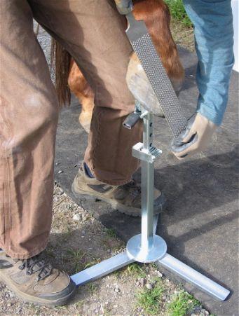
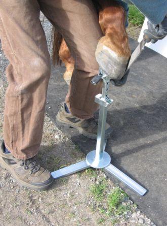
3 Work Station and Evo Hoof Stand Instructions p. 3 Once you have one leg aligned with the downward slope of the Grip Head, lay the stand on its side with two legs against the ground to brace it. Next use a wrench to very firmly tighten the Leg Stay Bolt. This bolt must always be kept tight to protect the legs from becoming loose. Check it after you have used the stand a while to make sure it remains tight. In this Standard Position, a hoof on Grip Head points toward one leg. Begin using your stand in this position. Later you can rotate the Grip Head to try different leg positions. Operating the Height Adjustment Selector To adjust the height of the stand, you simply push or pull on one end of the Height Adjustment Selector frame. This disengages its locking pin, allowing the inner shaft to move. If the height of the stand is low, the spring inside the stand shaft will elevate the inner shaft. If the height of the stand is already high, you simply push it down to the desired lower height and release the Height Selector frame. To disengage the Height Selector Pin by pushing, press your thumb on the flat end of the frame (not the 3/8 Plunger Rod that extends through the frame). To disengage by pulling, grasp the ends of the " rod that passes through the opposite, angled end of the frame. WARNING: Never use the stand without the white plastic stop inserted in the Height Selector frame, as this piece is essential to maintain the stability of the Height Selector Frame! Without the stop the stand height is not stable. And remember: at low heights the Inner Shaft can eject from the Outer Shaft when the Height Selector is disengaged! Keep one hand over it when you release the Selector at low height. Plastic Stop Push & Pull to disengage selector pin Changing height 1 handed & w/ hoof on Grip Head You can change height during use, with the hoof on the Grip Head or the Cradle, by lifting hoof and Grip Head or Cradle together while you disengage the Height Selector with your other hand. Bracing Evo Stands and Work Stations Positioning the Stand Under the Horse s Leg: For optimum stand stability, the horse s front leg is positioned so that its weight pushes directly downward onto the Grip Head. This position differs from one horse to another. When placing the leg on the Grip Head, lift it and pull it forward, feeling for the height and position in which the hoof tends to descend vertically downward. Position the stand under the hoof at that position. When placing the hoof on the Hoof Cradle, bend the leg and pull it backward to find the position in which the hoof tends to descend vertically onto the Hoof Cradle. Some horses will relax more if you stretch the leg forward and backward before placing the hoof on the stand. WARNING: Avoid having your fingers between the hoof and the Grip Head! Hold the hoof by the outer edges. Stand too close to horse Stand too far out Position stand so hoof drops directly down on Grip Head Placing Hoof on Grip Head: NOTE: These demonstrations done without an apron to show leg positions. Place to toward lower side of Grip Head Hold hoof by edges NOTE: Don t do this at home!


4 Work Station and Evo Hoof Stand Instructions p. 4 Basic Leg and Foot Bracing Positions: In many positions, the stand can be stabilized with one knee or the lower thigh against the hoof, or one foot on one leg of the stand. For increased stability, these two ways of bracing are combined. This is done with either the knee and foot of the same leg or knee and foot of your opposite legs. You can also use the heel of your shoe rather the toe on the ends of the stand legs. Occasionally, for maximum stability, you can use both feet on the stand legs or bring both knees together against the hoof. But this is rarely needed if you place the stand in the best position under the horse s leg. Proper bracing will usually allow you to work both sides of the hoof without changing your stance under the horse. There are multiple positions for your feet, both on and off the stand legs. Use these to position your legs so you can stabilize the top of the stand and the hoof on it with your knee or thigh. Think of creating a triangle or pyramid shape with the hoof or leg at its point. When a horse pulls its hoof off the Grip Head or Cradle, catch the hoof with your thigh or hand, hold it until the horse relaxes, then put it back on again. Triangulating your Bracing Toe & heel placement on Stand Legs Bracing front hooves on the Grip Head: 1 knee only bracing 1 foot only bracing 1 knee & 1 foot same leg 2 feet on 2 stand legs 1 knee & 1 foot of opposite legs 1 knee & both feet using heel & toe of boot Controlling tipping with front hooves on the Grip Head: Stand tipping backward Prevent w/ 1 foot on front leg or knee to hoof w/ Grip Head in reverse position


5 Work Station and Evo Hoof Stand Instructions p. 5 Bracing hind hooves on the Grip Head: 1 knee & 1 foot bracing Controlling Tipping 2 feet on 2 stand legs 2 feet & 1 Knee Bracing front hooves on the Hoof Cradle: Bracing the Hoof Cradle is similar to using the Grip Head. But with the Hoof Cradle, you often use your thigh against the pastern or your knee against the fetlock. You can also use one hand to stabilize the hoof as you work it. Place Cradle where hoof drops down onto it, with Grip Head toward hairline of hoof, so it does not interfere with tool use. Grip Head to hair line Hoof drops on Knee brace--your leg inside of horse leg Your leg outside horse s Bracing hind hooves on the Hoof Cradle: Stretching the horse s leg forward, up, and down, before putting it on the Cradle, can help relax it. Some horses need to retract the leg briefly after being on the Cradle for a couple minutes. Allow the retraction by holding the hoof as the leg moves forward, wait a moment, then replace the hoof on the Cradle. Stiff-legged horses might need to put the leg all the way down for a moment and then up again. Set the Cradle at the height that suits you best. If the horse is uncomfortable, adjust height. You can shift placement of the stand forward and backward, as well as inward or outward, to find the spot in which a horse is most comfortable, or to vary your position as you work. Use your upper arm to brace the inside of the hock of the leg. Change the positions of your legs and feet to gain the best access for your tools. Place slightly behind horse Bracing w/ 1 foot 1 foot & one Knee 2 feet 2 feet & one knee Thigh to fetlock Upper arm to hock, 1 knee & 1 foot Arm, 2 knees, 2 feet Allow brief leg retraction


6 Work Station and Evo Hoof Stand Instructions p. 6 Heel of foot on stand leg 1 knee to fetlock on Shorty stand Bracing mini horse hoof with front of your leg Hand bracing of hoof on Cradle of Grip Head: It is also effective to use one hand to brace the hoof against both the Hoof Cradle and the Grip Head as you work Hoof Cradle / Handle Positioning The Hoof Cradle rotates around a " rod mounted on the stand s Grip Head. When the rubber-covered arc of the Cradle is rotated upward, it drops into position for use. When it is lifted it becomes a handle to carry the stand. When rotated downward, it allows you to use the Grip Head. The cradle can also be removed from the Grip Head and hooked on the " rod attached to the frame of the Height Selector. To do this, put the cradle in the down position on the Grip Head, lift it slightly and pull it away from the Grip Head. The cradle will unhook from the Grip Head. Now hook the cradle on the Height Selector rod. Use this storage place if the Cradle interferes with your bracing of the hoof or stand. Down position Lift up or down Up position Handle grip Detach Stow position The fit of the Cradle on its bracket can be made tighter or looser by twisting the hose coverings. Adjust Cradle fit on bracket by twisting the Hose Removing and replacing Cradle Hose: Using the Hoof Cradle Positioning the Hoof on the Cradle: This Hoof Cradle is designed to support the hoof securely yet give you full access to it with your tools. Moving the hoof forward or backward across the Cradle alters areas of support. This changes both the angle of the bottom of the hoof and effects access to the hoof outer wall of the hoof. When working the front half of the hoof it is usually best to position the Cradle near the toe. When working the rear half of the hoof, heels, frog, and bars, it can be helpful to shift the Cradle nearer to the hairline.


7 Work Station and Evo Hoof Stand Instructions p. 7 How hoof position on Cradle changes your access to the outer wall & the angle of support for working the bottom of it To position Hoof Cradle at lowest height, remove Inner Stand Shaft and place Cradle in top of 1 Outer Shaft: Using the Hoof Cradle Extension on Shorty stands: This device enables you to get both hands on your nippers when trimming very small hooves. Pull Cradle Extension from magnet, insert in end of Cradle, place stand with Extension next to horse Brace horse s knee with your leg. See our video on trimming miniature horse hooves for more detail. Tool Use on the Hoof Cradle: The Evo Stands and Work Stations give you special advantages when using your regular tools hoof knife, nippers, and flat rasp. Some of these positions will be new, so take your time learning to use them. Front Hooves: Nippers and rasp w/ open stance Rasping in all directions, 2 and 1 handed, push and pull Hind Hooves: Rasping both directions on Cradle Rasping all of outer hoof wall on Grip Head Using the solid support of the Cradle for hoof knife work can increase your control and leverage.


8 Work Station and Evo Hoof Stand Instructions p. 8 Knife work on Cradle, front Hoof, pulling and pushing, Knife work on Cradle hind hoof Using other Evolutionary Hoof Care tools with your Evo Stand or Work Station The Evo Hoof Stands and Complete Hoof Care Work Stations are designed to facilitate your use of all hoof care tools including the new Radius Rasps, Hoof Buffers, and Sole Rasps. The Grip Head and Hoof Cradle provide solid support so you can apply your tools to greater effect with less effort. It will take you some time to discover all the ways you can use these stands to facilitate your trimming work. Be sure to shift the hoof around on both the Grip Head and Hoof Cradle to get the best access and positions for applying all your tools. Experiment with one handed grips that steady the hoof against the Cradle. Also remember to adjust your stance so you move around the stand to get into the best positions for using each tool on each part of the hoof. Be sure to view our videos on how to use our new tools with the Evo Stands and Work Stations. Hoof Buffers on Grip Head and Hoof Cradle Radius Rasps on Evo HS-1 Sole Rasp on Shorty Cradle Hoof Cradle as Stand Handle Function To use the Hoof Cradle as a handle for carrying the stand, lift the Cradle from its up position on the Grip Head and slide two fingers on either side of the Cradle shank. This allows you to carry the stand easily in one hand. You can grasp the arc of the Cradle from either side. When you slide your fingers under the Cradle from the Grip Head side, you can hook your middle finger under the opposite end of the rasp section of the Grip Head and gain an additional grip on the stand. Handle Lift and grips Handle carry Varying Grip Head Orientation Relative to Legs The Grip Head has a Standard Position in which it slants downward toward one stand leg. It is recommended that you use your Evo Stand or Work Station with the Grip Head in this position until you are familiar with how to brace it. But the Grip Head can be removed and rotated to 3 other positions. These different positions change how the stand legs are placed under the horse when you are using either the Grip Head or the Hoof Cradle. This offers you different placements for your feet on the stand legs. But when you change the position of the Grip Head you must also change


 B. Hoof Buffer (or Nippers etc.) C.")


9 Work Station and Evo Hoof Stand Instructions p. 9 your bracing of the stand. Changing Grip Head orientation also alters its alignment with the Height Selector frame. When the Grip Head and Frame are parallel, access to the Height Selector can be more difficult. It is easiest to remove the Grip Head by pushing its mounting pin out with your thumb, rather than pulling on the ring. Push pin with thumb, then pull out Rotating Grip Head changes alignment with Height Selector 4 directions of orientation for slant of Grip Head relative to legs: Standard Position Reverse Standard 90 degrees to Standard Position Photos below show stand with Cradle up, as it would be next to you, under the horse, with the sole of the hoof facing the top of the photo & the horse s leg in the direction of the green arrow. Stand leg positions change relative to orientation of the Grip Head on top of the Inner Stand Shaft. Note the different possible placements of your feet on the stand legs. Grip Head in Standard Position Reverse Standard 90 degrees to Standard #1 90 degrees to Standard #2 Using the WS-1 Standard Work Station Tool Caddy The WS-1 Standard Caddy is designed to carry a full set of hoof care tools. You can use the tubes as suites you best. Below are the recommended uses: Large Standard Caddy parts: CT: Center Tube fits over 1 Outer Shaft A. Hoof Nippers (or Hoof Buffer) B. Hoof Buffer (or Nippers etc.) C. Flat Hoof Rasp D. Flat Hoof Rasp E. Hoof Knife F. Sole Rasp G. Hole Rasp H. Radius Rasp Magnet Mounting Plate Insert your hoof nippers in tube A with the handles pointing downward. It is easiest to grasp them by the nipper head. Insert your flat hoof rasps into tubes C and D with the handles pointing upwards. Use the handles of the rasps to steer the Caddy around the central stand shaft to position your tools where these are easiest to reach while you are working on the hoof. Insert your Sole Rasps into tubes F and G with the central arc of the rasp against the sides of the larger


10 Work Station and Evo Hoof Stand Instructions p. 10 tubes, A and B. This position keeps them from sticking outward and getting in your way. Tube E is for your hoof knife. Mount your Radius Rasps on the two sides of the Magnet Mounting Plate s point, part H above. Insert your Hoof Buffer or other tools in tube B. Be sure to watch our videos on how to use your new model Tool Caddy. Standard Caddy w/ trim tools Trim and shoe tools Trim & shoe tools in Caddy Cleaning Caddy When using only one rasp, you have the choice of putting it in either rasp tube, C or D. Remember to use the rasp handles to steer the Caddy around the central shaft so that your tools are where you want them under the horse. You can also reposition the Caddy with the toe of your boot as you work, or push on the tops of your nippers. Nipper pull Rasp steer turning Caddy Tool access under horse Using the Sizing Insert Tube to adjust tool angle and Radius Rasp Magnet Mounting Plate The On-Board Mini Wire Brush that comes with your Caddy has many uses: Wire Brush in Caddy Wire brush pull Wire brush used to clean Hoof Buffer belt, Grip Head, Sole Rasp


11 Work Station and Evo Hoof Stand Instructions p. 11 Using the WS-2 Shorty Work Station Tool Caddy This version of the Tool Caddy is a more compact version made especially to fit the Shorty Evo Hoof Stand. You can use the tubes as suites you best. Below are the recommended uses: Shorty Caddy Parts: CT: Center Tube fits over 1 Stand Shaft A. Hoof Nippers B. Hoof Buffer (or other tools) C. Flat Hoof Rasp E. Hoof Knife F. Sole Rasp H. Radius Rasp and Hoof Cradle Extension Magnet Mounting Plate I: Position for Hoof Cradle Extension Magnet Insert your hoof nippers in tube A with the handles pointing downward. It is easiest to grasp them by the nipper head. Insert your flat hoof rasp into tube C with the handle pointing upwards. Use the handle of the rasp to steer the Caddy around the central stand shaft to position your tools where these are easiest to reach while you are working on the hoof. Insert your Sole Rasp tang down into tube F with the central arc of the rasp against the sides of the larger tube A. This position keeps it from sticking outward and getting in your way. Mount your Radius Rasps on the two sides of the Magnet Mounting Plate, part H above. Keep the flat Hoof Cradle Extension magnet positioned to one side of the bend in the Radius Rasp Mounting Plate and secure the Cradle Extension to it so it conforms to the bend of the Radius Rasp Magnet Plate. Caution: Remember that this powerful magnet is not a toy! Keep it away from children. Shorty Caddy tool array Trim tools in Caddy Radius Rasps on Mounting Plate w/ Hoof Cradle Extension between Using the Sizing Insert Tube to raise the angle of your tools Cleaning Caddy by turning it upside down Sole Rasp & Hoof Buffer Position in Shorty Caddy: Because of the Shorty Caddy s lower height, the Sole Rasp can sometimes catch on the stand legs and interfere with Caddy rotation. Be sure to insert the Sole Rasp in its tube pointed end first and at an angle, as shown below. If you encounter interference between your Hoof Buffer and the Height Adjustment Selector, you can use the Sizing Insert Tube to alter the position of the Hoof Buffer.


12 Work Station and Evo Hoof Stand Instructions p. 12 Correct Sole Rasp Position & Incorrect Hoof Buffer position change using Sizing Tube Mounting the Tool Caddy on Evo Hoof Stands The Work Stations come with Tool Caddies mounted on the 1 square outer stand shaft. However, if you purchase a Tool Caddy separately to convert your Evo Hoof Stand to a Complete Work Station, this is easily done. First you must remove the Push / Pull Height Adjustment Selector from the 1 stand shaft. To remove the Height Selector frame, push the white plastic stop up from the bottom and pull out from the top. Remove the! Inner Stand Shaft. Then grasp the 3/8 Plunger Rod and pull it to outward to compress the spring around it inside of the frame. Fully compress the spring so you can disengage the selector pin and lift the frame up off of the 1 Outer Stand Shaft. Keep track of all 4 parts do not lose the spring! See video of this process on our website. Push Stop up from bottom to remove Remove Inner Shaft Use pliers to hold spring back & lift frame off Before you install the Caddy, be sure to position the green plastic Base Buffer over the 1 Outer Stand Shaft. This part protects both the bottom of the Caddy and makes it rotate more smoothly. Place Base Buffer over Shaft Slide Caddy over Stand Shaft Replace Height Selector push Stop in firmly! If you are installing a Shorty Caddy, transfer the Cradle Extension Magnet from the Outer Shaft of your Evo Stand to the right side of the bend in the Radius Rasp Mounting Plate:


13 Work Station and Evo Hoof Stand Instructions p. 13 Take Care of you New Evo Hoof Stand or Work Station! We have done our best to make a sturdy, reliable tool for you. The steel parts have all been electrically plated with zinc to resist rust and corrosion. However, the zinc coating itself will oxidize and deteriorate if it is not kept clean and dry. Moisture and corrosive liquids are the enemy of steel and zinc. Your stand comes with a coating of light rust inhibiting oil. To keep it shiny you must occasionally clean and dry it, then apply a coat of rust inhibitor such as WD 40 to all its parts. Spray the oil on and wipe with a clean cloth. Be sure to oil the legs and stand base, as these are most exposed to dirt, friction, and moisture. Also oil all parts of the Height Selector, the Hoof Cradle, and the Grip Head including the inside of the 1 square socket on the Grip Head. Occasionally remove the legs and oil the surfaces that are bolted tight against the round base of the stand. Your Tool Caddy is made of solid aluminum tubing, thus it will not rust. It has been painted with a heavy-duty layer of powder coat paint. With use this paint will wear or chip. If you want to keep the paint in good condition you can order a bottle of touch up paint from us. With proper care your stand will remain bright for years to come. Remove plastic stop Lightly oil surfaces Wipe off excess oil Occasionally disassemble parts --- oil thoroughly and wipe off excess oil with a clean cloth There are even more details to learn about using your new hoof support device. So be sure to see the full video instructions for Evo Hoof Stands and Hoof Care Workstations Online at Evolve Your Hoof Care With tools from Evolutionary Hoof Care
Troyer s Gourd Rack 8 unit F R H O P
 B E A D I M-N L Vertical Parts F R H O P Horizontal Parts C G J Updated 11/16 Parts List A: Top of Pole B: Bottom of Pole C: 48 Ground Stake D: Top Perch rods 48 long E: Hub F: Rope Winder w/ attached
Stand-N-Fish FULL DETAIL INSTALLATION INSTRUCTIONS
 1 Stand-N-Fish FULL DETAIL INSTALLATION INSTRUCTIONS Thank you for purchasing the incredible new Stand-N-Fish Kayak Fishing System. Once installed on your kayak the Stand-N-Fish will take your kayak fishing
BELT DRIVE INDOOR CYCLING BIKE SF-B1712 USER MANUAL
 BELT DRIVE INDOOR CYCLING BIKE SF-B1712 USER MANUAL IMPORTANT! Please retain owner s manual for maintenance and adjustment instructions. Your satisfaction is very important to us, PLEASE DO NOT RETURN
Final Assembly Instructions Bikes with Quill Stems
 Final Assembly Instructions Bikes with Quill Stems Thank you for buying your new bicycle from L.L.Bean. Read these instructions carefully before beginning the final assembly. Prior to shipping, our expert
MAGNETIC INDOOR CYCLING BIKE
 MAGNETIC INDOOR CYCLING BIKE SF-B1805 USER MANUAL IMPORTANT! Please retain owner s manual for maintenance and adjustment instructions. Your satisfaction is very important to us, PLEASE DO NOT RETURN UNTIL
INSTRUCTION MANUAL. January 23, 2003, Revision 0
 INSTRUCTION MANUAL Model 810A In-Vitro Test Apparatus for 310B Muscle Lever January 23, 2003, Revision 0 Copyright 2003 Aurora Scientific Inc. Aurora Scientific Inc. 360 Industrial Parkway S., Unit 4 Aurora,
Barrel Assembly. Field Stripping
 WARNINGS: Carry out safety check before handling the weapon. The weapon is heavily oiled for shipping. Clean and lubricate before firing. These procedures given apply only to the US Ordnance QCB version.
User Guide. Tripod. flowtech 75 / 100 Tripod. Part No. S S
 User Guide flowtech 75 / 100 Tripod Tripod Part No. S2051-0001 S2052-0001 EN www.sachtler.com TM Copyright 2018 All rights reserved. Original Instructions: English All rights reserved throughout the world.
SERIES 2 RAMP OWNER S MANUAL TOOLS REQUIRED: BEFORE YOU BEGIN... Read and understand these instructions before beginning a ramp setup.
 SERIES 2 RAMP OWNER S MANUAL BEFORE YOU BEGIN... Read and understand these instructions before beginning a ramp setup. Use caution and care for your back when lifting, pushing, pulling, folding or unfolding
CHAPTER 2 MAINTENANCE
 CHAPTER 2 MAINTENANCE This chapter addresses the proper care of the machine gun to ensure its overall effectiveness and efficient functioning. The information includes the gunner's knowledge in disassembly
Lectric Cycles Mid-Drive Electric Motor Installation
 Lectric Cycles Mid-Drive Electric Motor Installation This write-up describes the installation of a Lectric Cycles electric motor. The model is the e-rad Mid-Drive 750 Watt conversion kit, installed on
DM-RD (English) Dealer s Manual. ROAD Rear Derailleur RD-9000 RD-6800 RD-5800 RD-4700
 Dealer s Manual. ROAD Rear Derailleur RD-9000 RD-6800 RD-5800 RD-4700") (English) DM-RD0003-09 ROAD Rear Derailleur Dealer s Manual RD-9000 RD-6800 RD-5800 RD-4700 CONTENTS IMPORTANT NOTICE...3 TO ENSURE SAFETY...4 LIST OF TOOLS TO BE USED...6 INSTALLATION...8 Chain length...
(English) DM-RD0003-09 ROAD Rear Derailleur Dealer s Manual RD-9000 RD-6800 RD-5800 RD-4700 CONTENTS IMPORTANT NOTICE...3 TO ENSURE SAFETY...4 LIST OF TOOLS TO BE USED...6 INSTALLATION...8 Chain length...
BELT DRIVE PREMIUM INDOOR CYCLING BIKE SF-B1509 USER MANUAL
 BELT DRIVE PREMIUM INDOOR CYCLING BIKE SF-B1509 USER MANUAL IMPORTANT! Please retain owner s manual for maintenance and adjustment instructions. Your satisfaction is very important to us, PLEASE DO NOT
Telescoping Attic Stair Operating Instructions
 Telescoping Attic Stair Operating Instructions 1. Opening the stairs: a. The provided pull cord and pull rod will be used to open and close the attic stair. If your stair has a pull cord, pull on the cord
Final Assembly Instructions Bikes with Threaded Headsets
 Final Assembly Instructions Bikes with Threaded Headsets Thank you for buying your new bicycle from L.L.Bean. Read these instructions carefully before beginning the final assembly. Prior to shipping, our
FIRST TEAM SPORTS, INC Storm Portable Series Assembly Instructions
 FIRST TEAM SPORTS, INC Storm Portable Series Assembly Instructions WARNING! WARNING! WARNING! THIS BASKETBALL SYSTEM IS SPRING LOADED AND SHIPPED UNDER TENSION. ATTEMPTING TO ASSEMBLE OR DISASSEMBLE ANY
SAFETY RULES WARNING: READ THESE SAFETY RULES & OPERATORS MANUAL BEFORE HANDLING YOUR FIREARM
 SAFETY RULES WARNING: READ THESE SAFETY RULES & OPERATORS MANUAL BEFORE HANDLING YOUR FIREARM Never point a firearm at anyone and always keep the muzzle pointed in a safe direction. Always treat all firearms
Boat Boat Loader Fitting Instructions
 Aerodynamic & Heavy Duty Roof Rack Systems Australian Made - Australian Owned www.rhinorack.com Boat Boat Loader Fitting Instructions CONTROLLED Balance point 3 Front eye nuts position 3 Transom eye nut
PARTNER With all partner stretches: communicate with partner and use caution!!
 - warm up prior to stretching - isolate the muscle group to be stretched - move slowly and smoothly into stretch - use proper mechanics and correct alignment - breathe normal - slowly come out of stretch
Before you start! Is iwalk 2.0 right for you?
 Before you start! Is iwalk 2.0 right for you? Physical Abilities Requirements 1. Stair Test Before your injury, could you easily walk up and down stairs at normal speed, without using the hand rail? 2.
USER S MANUAL QUESTIONS? CAUTION. Model No. FMEX Serial No. Write the serial number in the space above for reference. Serial Number Decal
 Model No. FMEX81110.0 Serial No. Write the serial number in the space above for reference. USER S MANUAL Serial Number Decal QUESTIONS? If you have questions, or if parts are damaged or missing, please
Cleaning rod: spring steel, stainless steel or carbon fibre cleaning rod - only use a one-piece rod. Avoid using snakes.
 Telemark Biathlon Where performance and precision come together http://telemarkbiathlon.com Rifle Cleaning Date : July 19, 2013 Anschutz Rifle Manual - Click Here Izhmash 7-3 Rifle Manual - still looking
HOME ASSEMBLY INSTRUCTIONS
 HOME ASSEMBLY INSTRUCTIONS This Papillionaire Bicycle now belongs to you. It will take you to work, wait patiently outside your local cafe, and carry your groceries home. This is the start of your long-term
COLT AUTOMATIC PISTOL
 COLT AUTOMATIC PISTOL CALIBER.22 INSTRUCTIONS FOR ASSEMBLY - DISASSEMBLY CLEANING COLT AIUTOMATIC PISTOL IN 6 INCH OR 4}~2 INCH BARREL.22 Long Rifle, rim fire Cartridge Capacity of Magazine, 10 Shots Description
600 / 600FC OWNER'S MANUAL
 PROGRESSION 600 / 600FC OWNER'S MANUAL Issue 2 / Version E - Dec. 10, 1997 Copyright 1997 GAMMA Sports - All Rights Reserved PROGRESSION 600 / 600FC OWNER'S MANUAL TABLE OF CONTENTS PAGE 1... WARRANTY
Final Assembly Instructions Bikes with Threaded Headsets
 Final Assembly Instructions Bikes with Threaded Headsets Thank you for buying your new bicycle from L.L.Bean. Read these instructions carefully before beginning the final assembly. Prior to shipping, our
RIFLE DRILL. 1. General. Before commencing instruction in rifle drill, it is important that the cadets receive instruction in the parts of the rifle.
 RIFLE DRILL 1. General. Before commencing instruction in rifle drill, it is important that the cadets receive instruction in the parts of the rifle. 2. Rifle Movements. Unless stated otherwise, cadets
8MAY15 US RACK, Inc Falcon Drive, Madera, CA
 8MAY15 US RACK, Inc. - 2850 Falcon Drive, Madera, CA 93637-559-661-3050 INSTRUCTIONS for Bedrail-mounted MOTORCYCLE RACK, Model 2001-4TRA WARNING: Do NOT attempt to install or use this rack without following
A. TO PREPARE THE MACHINE FOR USE.
 INSTRUCTION MANUAL FOR THE ML120 STRINGING MACHINE. CONTENTS: A. TO PREPARE THE MACHINE FOR USE. 1. The assembly of frame with console and tooltray. 2. Fixing the lever of the tension unit. 3. Putting
Universal Elevator Mount Owners Manual Customer Service Center N53 W24700 South Corporate Circle Sussex, WI U.S.A.
 REQUIRED TOOLS AND MATERIALS: 2 Capable Adults Carpenter s Level 15 Tape Measure Pencil Universal Elevator Mount Owners Manual Customer Service Center N53 W2400 South Corporate Circle Sussex, WI 530 U.S.A.
OWNER'S MANUAL. Copyright 1999 ATS - All Rights Reserved
 OWNER'S MANUAL AL Issue 2 - August 19, 1999 Copyright 1999 ATS - All Rights Reserved OWNER'S MANUAL TABLE OF CONTENTS PAGE 1... WARRANTY PAGE 2... ASSEMBLY INSTRUCTIONS PAGE 4... MOUNTING THE RACQUET PAGE
2990 Lorne Scots Royal Canadian Army Cadet Corps Rifle Drill
 2990 Lorne Scots Royal Canadian Army Cadet Corps Rifle Drill Page 1 of 27 TABLE OF CONTENTS PARA ITEM PAGE Section 1 BASIC RIFLE DRILL 1.1 INTRODUCTION 3 1.2 ATTENTION 5 1.3 STAND AT EASE FROM ATTENTION
Shot Technical Model
 Shot Technical Model Progression related to Multi-Events Development (aged 8/9-12 years) can be referenced to Athletics 365. Further technical information can be found HERE Linear Shot - Whole Sequence
Side-of-Pole Mount for 1 Module (SPM1) For Module Types A & B
 For Module Types A & B") Side-of-Pole Mount for 1 Module (SPM1) For Module Types A & B ASSEMBLY INSTRUCTIONS step-by-step assembly and installation Version 1, Rev A PCN 080311-2 SP3363-1 Side-of-Pole Mount for 1 Module (SPM1)
Side-of-Pole Mount for 1 Module (SPM1) For Module Types A & B ASSEMBLY INSTRUCTIONS step-by-step assembly and installation Version 1, Rev A PCN 080311-2 SP3363-1 Side-of-Pole Mount for 1 Module (SPM1)
Final Assembly Instructions Bikes with 16 Wheel Size
 Final Assembly Instructions Bikes with 16 Wheel Size Thank you for buying your new bicycle from L.L.Bean. Read these instructions carefully before beginning the final assembly. Prior to shipping, our expert
BOTTOM BRACKET BEARINGS
 BOTTOM BRACKET BEARINGS This basic tutorial will demonstrate the workings of a typical 3 piece bottom bracket, showing the removal and installation of the various components that make up the bearing system.
LESSON 7: THE PRONE POSITION
 LESSON 7: THE PRONE POSITION PURPOSE This lesson introduces you to the correct technique for firing in the prone position. INTRODUCTION prone sling The prone position has the lowest center of gravity and
Assembly, Fitting, Care & Maintenance
 Assembly, Fitting, Care & Maintenance Assembly 1.1 Remove All Parts and Tools from Packaging 1.2 Part and Tools required for assembly 1.3 Check Foot & Leg Assembly 1.4 Adjust Upper-Leg-Support (ULS) Height
Santa Fe Cycles Assembly Guide Introduction
 Santa Fe Cycles Assembly Guide Introduction Congratulations on your purchase of your new Santa Fe bicycle. You have purchased a bicycle that has many features and qualities. Please take a few minutes and
DM-MARD (English) Dealer's Manual. ROAD MTB Trekking. City Touring/ Comfort Bike REAR DERAILLEUR XTR RD-M9100 RD-M9120
 Dealer's Manual. ROAD MTB Trekking. City Touring/ Comfort Bike REAR DERAILLEUR XTR RD-M9100 RD-M9120") (English) DM-MARD001-00 Dealer's Manual ROAD MTB Trekking City Touring/ Comfort Bike URBAN SPORT E-BIKE REAR DERAILLEUR XTR RD-M9100 RD-M9120 CONTENTS CONTENTS...2 IMPORTANT NOTICE...3 TO ENSURE SAFETY...4
(English) DM-MARD001-00 Dealer's Manual ROAD MTB Trekking City Touring/ Comfort Bike URBAN SPORT E-BIKE REAR DERAILLEUR XTR RD-M9100 RD-M9120 CONTENTS CONTENTS...2 IMPORTANT NOTICE...3 TO ENSURE SAFETY...4
OWNER'S MANUAL. Copyright 2003 GAMMA - All Rights Reserved
 OWNER'S MANUAL AL Issue 1 - December 2003 Copyright 2003 GAMMA - All Rights Reserved OWNER'S MANUAL TABLE OF CONTENTS PAGE 1... WARRANTY PAGE 2... ASSEMBLY INSTRUCTIONS PAGE 4... MOUNTING THE RACQUET PAGE
Trampoline & Enclosure Assembly Instructions
 Trampoline & Enclosure Assembly Instructions Safe user weight 330 lbs (150 kg) Version 718702 The information in this document is subject to change without notice. Copyright Springfree Trampoline Inc.
BELT DRIVE PREMIUM INDOOR CYCLING BIKE SF-B1509 USER MANUAL
 BELT DRIVE PREMIUM INDOOR CYCLING BIKE SF-B1509 USER MANUAL IMPORTANT! Read all instructions carefully before using this product. Retain owner s manual for future reference. For customer service, please
RS Important Notes. Contact. Bicycle Maintenance Stand instructions manual. Warranty Period : 1 year (from the date of your purchase)
") Warranty Period : 1 year (from the date of your purchase) RS-1700 Bicycle Maintenance Stand instructions manual (ver.1.2 2016/12) For more details, read the attached "Minoura Limited Warranty Policy" card.
Warranty Period : 1 year (from the date of your purchase) RS-1700 Bicycle Maintenance Stand instructions manual (ver.1.2 2016/12) For more details, read the attached "Minoura Limited Warranty Policy" card.
2-1. CLEARING PROCEDURES
 CHAPTER 2 MAINTENANCE Proper maintenance contributes to weapon effectiveness as well as unit readiness. This chapter discusses the maintenance aspects of the M249 AR to include inspection; cleaning and
INDOOR CYCLING BIKE SF-B1110 USER MANUAL
 INDOOR CYCLING BIKE SF-B1110 USER MANUAL IMPORTANT! Read all instructions carefully before using this product. Retain owner s manual for future reference. For customer service, please contact: support@sunnyhealthfitness.com
Installation. Striping Kit for 42in and 50in Mowers Model No Installation Instructions. Removing the Mower Deck.
 Striping Kit for 42in and 50in Mowers Model No. 120 7905 Form No. 3368-794 Rev B Installation Instructions Installation Loose Parts Use the chart below to verify that all parts have been shipped. Procedure
Fitting Instructions. Tailor the fit of your iwalkfree. Wearing for the first time. Set the Knee platform height
 Fitting Instructions Tailor the fit of your iwalkfree Now we will cover how to tailor the fit of your iwalkfree. Adjustments are quick and easy and require no tools just be sure that you have ordered the
Front derailleur. Dealer's Manual SORA FD-R3000 FD-R3030 CLARIS FD-R2000 FD-R2030. ROAD MTB Trekking. City Touring/ Comfort Bike DM-RBFD001-01
 (English) DM-RBFD001-01 Dealer's Manual ROAD MTB Trekking City Touring/ Comfort Bike URBAN SPORT E-BIKE Front derailleur SORA FD-R3000 FD-R3030 CLARIS FD-R2000 FD-R2030 CONTENTS IMPORTANT NOTICE... 3 TO
#59114 Rola 2-Bike Rack Carrier (Shown Assembled) (A) (C) (B)
 (A) (C) (B)") Use for Parts: #59114 Rola -Bike Rack System #59115 Rola 1-Bike Add-On TOOLS REQUIRED 10mm or 13/3 Socket & Wrench #59114 Rola -Bike Rack Carrier (Shown Assembled) Tray Attachment Hardware: (3) Plastic
Use for Parts: #59114 Rola -Bike Rack System #59115 Rola 1-Bike Add-On TOOLS REQUIRED 10mm or 13/3 Socket & Wrench #59114 Rola -Bike Rack Carrier (Shown Assembled) Tray Attachment Hardware: (3) Plastic
Road Chain Catcher Installation Instructions (K13-001, K13-006, K SL1, K SL2)
") Road Chain Catcher Installation Instructions (K13-001, K13-006, K13-001-SL1, K13-001-SL2) Description: The K-Edge Road Chain Catcher series is designed to eliminate chain drop on the lowest chainring due
Road Chain Catcher Installation Instructions (K13-001, K13-006, K13-001-SL1, K13-001-SL2) Description: The K-Edge Road Chain Catcher series is designed to eliminate chain drop on the lowest chainring due
AR STYLE FIREARMS OWNER'S MANUAL: OPERATION, HANDLING, DISASSEMBLY / REASSEMBLY & SAFETY INSTRUCTIONS
 AR STYLE FIREARMS OWNER'S MANUAL: OPERATION, HANDLING, DISASSEMBLY / REASSEMBLY & SAFETY INSTRUCTIONS - DO NOT DISCARD THIS MANUAL - READ THIS MANUAL CAREFULLY, PAYING CLOSE ATTENTION TO THE INSTRUCTIONS
QUALITY ALUMINUM BOAT LIFTS, INC. INSTRUCTIONS. Dominator Lake Lift
 INSTRUCTIONS Dominator Lake Lift PHONE:251-986-3882 * FAX:251-986-3136 QABLDOMINATORINST.2014 P a g e 1 Quality Aluminum Boat Lifts, INC. Installation Instructions: Dominator Lake Lift Thank you for your
VERSA BIKE RACK INSTRUCTIONS
 VERSA BIKE RACK INSTRUCTIONS Models #8, 8 Important This rack is designed for use with a or. receiver hitch. The rack is designed to hold a maximum of two bicycles. Do not use it for anything other than
Javelin Technical Model
 Javelin Technical Model Progression related to Multi-Events Development (aged 8/9-12 years) can be referenced to Athletics 365. Further technical information can be found HERE Whole Sequence The javelin
Assembly Instructions. -Cantilever Boat Lifts
 Assembly Instructions -Cantilever Boat Lifts Winch Instruction Page Safety Information 1. The winch is built for the multipurpose of hauling and lifting operations. It is not to be used as a hoist for
BELT DRIVE INDOOR CYCLING BIKE SF-B1712
 BELT DRIVE INDOOR CYCLING BIKE SF-B1712 USER MANUAL IMPORTANT! Read all instructions carefully before using this product. Retain owner s manual for future reference. For customer service, please contact:
DM-RARD (English) Dealer's Manual. ROAD MTB Trekking. City Touring/ Comfort Bike. Rear Derailleur DURA-ACE RD-R9100 ULTEGRA RD-R8000
 Dealer's Manual. ROAD MTB Trekking. City Touring/ Comfort Bike. Rear Derailleur DURA-ACE RD-R9100 ULTEGRA RD-R8000") (English) DM-RARD001-03 Dealer's Manual ROAD MTB Trekking City Touring/ Comfort Bike URBAN SPORT E-BIKE Rear Derailleur DURA-ACE RD-R9100 ULTEGRA RD-R8000 CONTENTS IMPORTANT NOTICE... 3 TO ENSURE SAFETY...
(English) DM-RARD001-03 Dealer's Manual ROAD MTB Trekking City Touring/ Comfort Bike URBAN SPORT E-BIKE Rear Derailleur DURA-ACE RD-R9100 ULTEGRA RD-R8000 CONTENTS IMPORTANT NOTICE... 3 TO ENSURE SAFETY...
SKYBIRD TRAP OWNER S / OPERATOR S MANUAL PARTS AND ASSEMBLY INSTRUCTIONS
 SKYBIRD TRAP PART NO. 40903 OWNER S / OPERATOR S MANUAL PARTS AND ASSEMBLY INSTRUCTIONS WARNING: THIS MACHINE CAN CAUSE SERIOUS INJURY OR DEATH! THOROUGHLY READ INSTRUCTIONS AND SAFETY INFORMATION BEFORE
602 STRINGING MACHINE OWNER'S MANUAL
 PROGRESSION 602 STRINGING MACHINE OWNER'S MANUAL AL Issue 1- April 2000 Copyright 2000 GAMMA Sports - All Rights Reserved PROGRESSION 602 STRINGING MACHINE TABLE OF CONTENTS PAGE 1... WARRANTY PAGE 2...
Trampoline & Enclosure Assembly Instructions
 Trampoline & Enclosure Assembly Instructions Safe user weight 250 lbs (115 kg) Version 718602 The information in this document is subject to change without notice. Copyright Springfree Trampoline Inc.
M16 R / M1600 R USER S MANUAL WARNING: READ THE INSTRUCTIONS AND SAFETY PRECAUTIONS IN THIS MANUAL CAREFULLY BEFORE USING THIS FIREARM.
 ARMSCOR M16 R / M1600 R USER S MANUAL WARNING: READ THE INSTRUCTIONS AND SAFETY PRECAUTIONS IN THIS MANUAL CAREFULLY BEFORE USING THIS FIREARM. DISCHARGING FIREARMS IN POOLY VENTILATED AREAS, CLEANING
Tadasana Variation 7. Thighs back, buttocks in (with two helpers)
") Tadasana Variation 7 Pro ps 2 ropes or belts, Thighs back, buttocks in (with two helpers) 2 helpers This variation produces a similar effect to the previous one but with a different method. Stand in Tadasana
Tadasana Variation 7 Pro ps 2 ropes or belts, Thighs back, buttocks in (with two helpers) 2 helpers This variation produces a similar effect to the previous one but with a different method. Stand in Tadasana
HoldUp Plus2. Safety Kit included: See additional instructions for installation. REAR WHEEL TRAY. BASE (1x) lock WASHER (1x) KEY (2x) SAFETY CLIP (1x)
 lock WASHER (1x) KEY (2x) SAFETY CLIP (1x)") HoldUp Plus2 InsTAll This product on 2" hitch version of the HoldUp Front WHEEL TRAY assembly (1x) REAR WHEEL TRAY assembly (1x) wrench (1x) BASE (1x) bolt (8X) Lock WASHER (8X) Washer (8x) KEY (2x) SAFETY
HoldUp Plus2 InsTAll This product on 2" hitch version of the HoldUp Front WHEEL TRAY assembly (1x) REAR WHEEL TRAY assembly (1x) wrench (1x) BASE (1x) bolt (8X) Lock WASHER (8X) Washer (8x) KEY (2x) SAFETY
RIDE Inc. Rigscape Service Rig Procedures
 2016 RIDE Inc. Rigscape Service Rig Procedures Special Instructions/Conditions of Use Reading user procedure manual prior to use is essential Only persons that have been deemed competent in the operation
CHAPTER 4 ADVANCED GROUND-FIGHTING TECHNIQUES
 (FM 21-150) CHAPTER 4 ADVANCED GROUND-FIGHTING TECHNIQUES After achieving an understanding of the basics of ground fighting, other elements of fighting on the ground are added. These techniques, however,
Drive Belt Instructions
 Drive Belt Safety Do not roll, pry, twist, invert or bend the belt back on itself. Do not zip tie the belt. The acceptable temperature range for your belt drive is -53 C to 85 C. Do not lubricate the belt
Falcon 3 145, 170, 195 and Tandem Owner / Service Manual
 Falcon 3 145, 170, 195 and Tandem Owner / Service Manual January 2007 - Second Edition Removing The Sail From The Airframe And Short Packing The Glider Many maintenance and repair procedures will require
Key Terms. balance barrel bolt butt hand guard muzzle port arms sling stacking swivel stock trail arms trigger guard
 Lesson 7 Stationary Movements with the M-1 Rifle Chapter 5 Key Terms balance barrel bolt butt hand guard muzzle port arms sling stacking swivel stock trail arms trigger guard What You Will Learn to Do
CHAPTER 5 REWIND STARTERS
 GENERAL INFORMATION CHAPTER 5 REWIND S Rewind starters used on vertical shaft Tecumseh engines are top mount horizontal pull style or side mount vertical pull style. Horizontal shaft engines use side mounted
X-6 STRINGING MACHINE OWNER'S MANUAL. Issue 1 - May Copyright 2004 GAMMA Sports - All Rights Reserved
 X-6 STRINGING MACHINE OWNER'S MANUAL Issue 1 - May 2004 Copyright 2004 GAMMA Sports - All Rights Reserved OWNER'S MANUAL GAMMA X-6 TABLE OF CONTENTS PAGE 1... WARRANTY PAGE 2... FEATURES PAGE 3...ASSEMBLY
Front derailleur. Dealer's Manual DURA-ACE FD-R9100 ULTEGRA FD-R FD ROAD MTB Trekking. City Touring/ Comfort Bike DM-RAFD001-03
 (English) DM-RAFD001-03 Dealer's Manual ROAD MTB Trekking City Touring/ Comfort Bike URBAN SPORT E-BIKE Front derailleur DURA-ACE FD-R9100 ULTEGRA FD-R8000 105 FD-5801 Procedures for cable tension adjustment
L810. Owner s Operating and. Maintenance Manual. For Standard Wheelchairs
 L810 Owner s Operating and Maintenance Manual For Standard Wheelchairs Introduction Standard wheelchairs are the result of extensive engineering research, and rigid quality assurance testing. Every new
U STAND INSTALLATION INSTRUCTIONS
 U STAND INSTALLATION INSTRUCTIONS Thank you for purchasing the incredible new U STAND by Stand N Fish. Once installed on your kayak the U STAND will enhance your kayak fishing enjoyment to a whole new
SAFETY FIRST. Inspection Proper Set Up Proper Climbing & Use Proper Storage & Carrying Operating Instructions
 SAFETY FIRST Inspection Proper Set Up Proper Climbing & Use Proper Storage & Carrying Operating Instructions Max weight on the 18 inch platforms 500 pounds SWL Certified at 2,000 pounds. Qualified under
Figure 2-1. SAFE ( S ) position.
 position.") CHAPTER 2 OPERATION AND FUNCTION This chapter includes clearing, disassembly and assembly, loading, operating precautions, and cycle of operation. 2-1. CLEARING Clear the MK 19 differently in a firing
CHAPTER 2 OPERATION AND FUNCTION This chapter includes clearing, disassembly and assembly, loading, operating precautions, and cycle of operation. 2-1. CLEARING Clear the MK 19 differently in a firing
Important Note: Tighten lock nuts so the support tubes still swing freely see figure 2. There must be 1 2 threads of bolt past end of lock nuts.
 Kit Contents: DESCRIPTION QTY. DESCRIPTION QTY. 2 Shank Assembly 1 Support Tube Assembly 1 Side Tube - Short 2 1-1/4 Shank 1 Center Tube - Long 1 3/8-16 x 2.0 Carriage Bolt 2 5/16-18 x 2.25 Carriage Bolt
CRUZBIKE Quest 2.0 Assembly
 CRUZBIKE Quest 2.0 Assembly CRUZBIKE Quest 2.0 Assembly... 1 General notes on assembly... 2 Un box and evaluate the frame and major parts... 2 Unfold the rear swing arm and arrange the frame... 3 Rear
PUN M Manual Finger Punch Safety and Operation Manual
 PUN M Manual Finger Punch 300-600 - 900 Safety and Operation Manual For punching thermoplastic belting materials only. WARNING IMPROPER OR UNSAFE use of this tool can result in serious bodily injury! This
Parts: Included in the parts box: Inner Rear Tire Tray. Inner Front Tire Tray. Trail Doc Clamp. Pivot Assembly. Trail Doc Post.
 NV 2.0 2 Parts: Outer Front Tire Tray Inner Front Tire Tray Outer Rear Tire Tray Inner Rear Tire Tray Pivot Assembly Trail Doc Clamp Trail Doc Post Included in the parts box: 6mm Allen Wrench M6 Lock Washer
DIRECT DRIVE DIXIE DOUBLE SEAMER Model 25D
 OPERATOR'S MANUAL DIRECT DRIVE DIXIE DOUBLE SEAMER Model 25D LUBRICATE DAILY: A. Gears inside gear housing at chuck shaft (1) Oil B. Seam rolls and cam rolls (4) - Oil C. Seam roll levers through gear
DM-MBRD (English) Dealer's Manual. ROAD MTB Trekking. City Touring/ Comfort Bike. Rear Derailleur SLX RD-M7000 DEORE RD-M6000
 Dealer's Manual. ROAD MTB Trekking. City Touring/ Comfort Bike. Rear Derailleur SLX RD-M7000 DEORE RD-M6000") (English) DM-MBRD001-04 Dealer's Manual ROAD MTB Trekking City Touring/ Comfort Bike URBAN SPORT E-BIKE Rear Derailleur SLX RD-M7000 DEORE RD-M6000 CONTENTS IMPORTANT NOTICE... 3 TO ENSURE SAFETY... 4
(English) DM-MBRD001-04 Dealer's Manual ROAD MTB Trekking City Touring/ Comfort Bike URBAN SPORT E-BIKE Rear Derailleur SLX RD-M7000 DEORE RD-M6000 CONTENTS IMPORTANT NOTICE... 3 TO ENSURE SAFETY... 4
RB70 Automatic Diluent Valve Maintenance Manual. Version 1.1 November 2006 Written by Tino de Rijk. Page 1 of 23
 RB70 Automatic Diluent Valve Maintenance Manual Version 1.1 November 2006 Written by Tino de Rijk Page 1 of 23 Table of Contents 1. Introduction... 3 2. ADV diagram and parts list (Pre June 2006)... 4
Product Overview: Key Features:
 APGL4 Model Tripod Product Overview: The Ravelli APGL4 is a Professional Quality Tripod providing a solid base for high-end photographic equipment. This model is all pressure treated aluminum alloy construction
7130 Lancer Rear Drive Magnetic Commercial Indoor Cycling Bike
 7130 Lancer Rear Drive Magnetic Commercial Indoor Cycling Bike Owner s Manual Made in Taiwan INDEX IMPORTANT SAFETY INFORMATION... 1 EXPLODED DRAWING... 2 PARTS LIST... 3 ASSEMBLY INSTRUCTION... 4-9 USER
E. Test, and if needed, adjust tips of antenna. 1. Mark will test antennas with meter at ground end of feedline bundle. Will take 10 minutes.
 Project Steps Overview: A. Prepare: B. Raise up small antenna. C. Raise up large antenna. D. Connect to new bundle of 4-feedlines pulled up from ground. E. Test, and if needed, adjust tips of large antenna.
 WALKING / K-WALKER 149K Strovolou Avenue, Strovolos, Nicosia, 2048, Cyprus T: +357 22250115, F: +357 22250116, M: +357 70008830 www.abletools.com.cy info@abletools.com.cy B SERIES KAYE POSTURE CONTROL
Front derailleur. Dealer's Manual FD-M9000 FD-M9020 FD-M9025 FD-M8000 FD-M8020 FD-M8025 FD-M612 FD-M617 FD-M618 FD-M672 FD-M677
 (English) DM-FD0003-05 Front derailleur Dealer's Manual FD-M9000 FD-M9020 FD-M9025 FD-M8000 FD-M8020 FD-M8025 FD-M612 FD-M617 FD-M618 FD-M672 FD-M677 CONTENTS IMPORTANT NOTICE... 4 TO ENSURE SAFETY...
ANTARES. User Manual ANTARES OVAL DRY GLOVE SYSTEM BY SI TECH. Photo: Jonas Andersson, Lysekil
 ANTARES User Manual Photo: Jonas Andersson, Lysekil ANTARES OVAL DRY GLOVE SYSTEM BY SI TECH ANTARES - User manual We want to congratulate you on your purchase of the ANTARES, a Dry Glove System developed
Aviation Rescue Swimmer School
 Aviation Rescue Swimmer School Releases and Escapes LT 3.2 JANUARY 2004 1 Enabling Objectives List procedural steps for rescue swimmer head hold releases and escapes in accordance with NWP 3-50.13 series.
E-trike Li Assembly Guide
 PREPARATION 1. Read this assembly manual BEFORE commencing assembly. 2. Carefully remove all the components and packaged hardware from the shipping boxes. 3. Unpack the contents of the large double box
L-23 Super Blanik Rigging (assembly/disassembly) Guide Maj Carl Kerns
 Guide Maj Carl Kerns") L-23 Super Blanik Rigging (assembly/disassembly) Guide Maj Carl Kerns The L-23 Blanik is a difficult Sailplane to rig (assemble). The wings are heavy and are secured via a single
L-23 Super Blanik Rigging (assembly/disassembly) Guide Maj Carl Kerns The L-23 Blanik is a difficult Sailplane to rig (assemble). The wings are heavy and are secured via a single
MUSKET MANUAL OF ARMS FOR THE
 MANUAL OF ARMS FOR THE MUSKET 414. This manual differs in so many respects from that of the rifle and rifle musket that it becomes necessary to specify it for the use of infantry troops armed with the
Player Development. Pitching 1
 Pitching Player Development Pitching 1 Delivery Mechanics Checklist: 1. Feet slightly spread on throwing arm side of rubber 2. Body weight positioned over stride leg 3. Torso upright 4. Hips and shoulders
LESSON 12: STATIONARY MOVEMENTS WITH THE M-1903 RIFLE
 LESSON 12: STATIONARY MOVEMENTS WITH THE M-1903 RIFLE PURPOSE balance barrel bolt port arms sight sling sling swivel stacking swivel This lesson introduces the procedures for executing the manual of arms
Deluxe Gourd Racks I D E G A. Parts List. Shown above are parts for the two-level, Deluxe Gourd Rack (DGR 12V)with 12 arms for vertically hung gourds.
with 12 arms for vertically hung gourds.") Deluxe Gourd Racks H F K I D E J C G A Shown above are parts for the two-level, Deluxe Gourd Rack (DGR V)with arms for vertically hung gourds. Parts List Code Quantity A B C D E F G H I J 6, or 4 6, or
Deluxe Gourd Racks H F K I D E J C G A Shown above are parts for the two-level, Deluxe Gourd Rack (DGR V)with arms for vertically hung gourds. Parts List Code Quantity A B C D E F G H I J 6, or 4 6, or
Mini Mr.Bulletfeeder by Double-Alpha
 Mini Mr.Bulletfeeder by Double-Alpha User Manual Thank you for choosing the Mini Mr.Bulletfeeder by Double-Alpha! This newly designed product will give you years of reliable service. It will make your
Bladerider X8 Assembly Help Notes
 2.1 Remove All Parts & Have Some Tools Handy Remove all items from the box and identify each part as per the packing sheet and check that nothing is missing. If there is something missing, please email
II-28 STOKES BASKET OPERATIONS
 1 II-28 STOKES BASKET OPERATIONS Anchor Slings- (2) high strength nylon webbing straps with D-rings on both ends used to set an anchor. Max working load of 10,000 lbs. Bight- Element of knot formed by
F-1279-R UPPER RIGHT SKIN F-1280-R RIGHT SIDE SKIN F-1281-R LOWER RIGHT SKIN F-1208-R FUSELAGE FRAME
 F-1282-R BOTTOM RIGHT SKIN F-1283C J-STIFFENER F-1278 TOP SKIN F-00009-L ADAHRS BRACKET F-00009-R ADAHRS BRACKET F-1279-R UPPER RIGHT SKIN F-1280-R RIGHT SIDE SKIN SECTION 10: TAILCONE F-1279-L UPPER LEFT