Baying and lifting. Whitepaper
|
|
|
- Millicent Paul
- 6 years ago
- Views:
Transcription

1 Baying and lifting Whitepaper

2 Table of contents Introduction... 4 Enclosures baying... 6 Floor standing enclosures... 8 Side to side baying... 8 Internal baying brackets CCI External baying brackets CCE Corner baying kit CCM Internal separation Separation plate SPD Continuous mounting Filler plate MPF Wide mounting plate MPW Back to back baying Depth baying kit CJDN Internal separation Mounting plate MP Partial mounting plate MPP Corner baying Depth baying kit CJDS Internal separation Separation plate SPD Side mounting plate MPS Wall mounted enclosures Side to side baying Wall mounted combining kit CK Top to bottom baying Gland plate combining gaskets AGC Enclosures lifting Floor standing enclosures Stand alone enclosures Lifting eye bolts LE9304(SS) Lifting kit MCUK Side to side enclosures Lifting eye bolts LE9304 (SS) Lifting device LC Back to back bayed enclosures Cornered bayed enclosures Wall mounted enclosures Single enclosure Lifting eyes AL Eldon White Paper - BAYING AND LIFTING 3

3 INTRODUCTION This white paper has been prepared and created by Eldon to support customers with information on how to lift and bay enclosures. Eldon also want to support customers in being able to make the best baying and lifting choices for enclosures based on their requirements as well as site limitations. Eldon s wall mounted and floor standing enclosures are continuously changing to meet demanding requirements customers and the engineering industry desire, which includes installation in a wide range of environments, accessory compatibility, ease of installation and to limit damage where possible. Eldon not only supply high quality enclosures to meet stringent industrial requirements but also offer a wide range in supporting documentation such as this white paper, to provide the technical information needed for supporting customers and to make their job as easy as possible. Eldon ensure that its enclosures are tested to the strictest of standards by highly recognised independent testing laboratories. Certifications are published on Eldon s websites which provides confidence to customers when using enclosures, peripherals and accessories. General notes This white paper and all technical descriptions regarding Eldon s enclosures do not represent warranted qualities and therefore Eldon are unable to accept liability with regard to deviations. Eldon reserves the right to extend or modify this technical documentation at any time. All of the technical information contained within this white paper is applicable to Eldon s enclosures only. For any questions or suggestions with regards to this technical white paper please do not hesitate to contact your local sales representative or partner. The internationally recognised IEC EN standard stipulates all of the requirements that need to be met with regards to enclosures that are used in low-voltage switchgear and controlgear assemblies. In compliance to the standard Eldon have provided a series of white papers to make all necessary information easily available and interpretable by its direct and in-direct customers. Eldon s wall mounted and floor standing enclosures are tested for loading and lifting capabilities in accordance with IEC EN Within this test the enclosures are loaded to a specific weight, lifted and moved several times to ensure that the enclosures are still functional and in good quality. Enclosure installations are deemed to be as difficult as the installation site permits. Due to the pressures of the industrial market, it is paramount that installations are carried out in an efficient and effective way meaning the installation time is as low as possible while ensuring health and safety is always taken into consideration. Measurements are displayed in millimetres (mm) and loads are given in Newton s (N) as a display of force. The formula to work out a force is shown below along with a conversion to the kilogram (Kg). Force (N) = mass (Kg) x acceleration (m/s 2 ) Acceleration due to gravity is measured at 9.8m/s 2 and occurs when an object is falling to the earth. 1 N is a force of 1 with acceleration due to gravity with means from the above formula that the below applies when converting from Force (N) to mass (Kg). 1N = 1Kg x 9.8(m/s 2 ) = 9.8Kg Therefore, one newton equals 9.8 kilograms. 4 Eldon White Paper - BAYING AND LIFTING Eldon White Paper - BAYING AND LIFTING 5


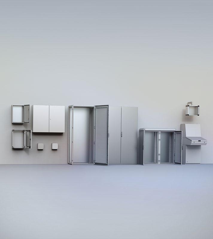
4 ENCLOSURES BAYING Eldon s enclosures can be bayed together to create larger enclosure configurations. Eldon s floor standing enclosures support baying in all directions as well as in two axes for wall mounted enclosures. This is thanks to the innovative profile system. Common configurations FLOOR STANDING ENCLOSURES Bayed enclosure configurations are perfect systems where there is a requirement for multiple operations that require segregation due to ingress protection (i.e. power distribution) or due to the enclosures having both inputs and outputs (i.e. field signals and automation). Eldon complements all baying configurations with an array of accessories. The required accessories depend on how the enclosures are bayed together, the enclosure s material and the installation environment. Baying accessories should be used to enhance the enclosure s strength, rigidity and to not deteriorate the enclosure s ingress and impact protection ratings. Side to side baying Conventional baying solution that is deemed very popular in the automotive and processing industries. This configuration is used both for automation and for power distribution. The number of enclosures bayed side to side can be infinite depending on customers requirements. Back to back baying Accessible configuration to ensure operators have access to both doors on the enclosures. As the enclosures are useable from both sides, this configuration is very useful when enclosures are mounted in the centre of its environment (i.e. data centres and control rooms). Perfect solution for confined spaces. Corner baying When there is limited installation space, corner baying configurations are ideal. These configurations are often used in mechanical engineering plants. WALL MOUNTED ENCLOSURES Side to side baying Top to bottom baying Conventional baying solution that is deemed very popular in the automotive and processing industries. This configuration is used both for automation and for power distribution. The number of enclosures bayed side to side can be infinite depending on customers requirements. When there is limited installation space, corner baying configurations are ideal. These configurations are often used in mechanical engineering plants. 6 Eldon White Paper - BAYING AND LIFTING Eldon White Paper - BAYING AND LIFTING 7


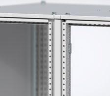
5 SIDE TO SIDE BAYING Internal baying brackets CCI06 Description: Internal baying brackets provide a rigid reinforcement of the enclosure assembly. The correct spacing between the enclosures is assured. Internal baying brackets are installed using click-in fixation points dramatically reducing the required installation time. To remove the click-in baying brackets a quarter turn from a cross head screwdriver is required. Mounting instructions MOUNTING Enclosure compatibility: Floor standing combinable enclosures: MCS, MCD, MCSS, MCDS, ECOM Installation: Eldon s standard side to side enclosure configurations are bayed using six internal baying brackets, three individually spaced down each vertical profile along with an internal corner baying kit. Limitations: Internal baying brackets cannot be used if a separation plate, SPD, is required. DEMOUNTING 8 Eldon White Paper - BAYING AND LIFTING Eldon White Paper - BAYING AND LIFTING 9

6 SIDE TO SIDE BAYING Application Baying brackets should be used when an enclosure needs to be bayed next to another to extend the internal space for the installation of components, switchgear and other electrical devices. As explained, Eldon provides three different types of baying brackets/kits for baying enclosures side to side: internal baying brackets CCI, external baying brackets CCE, and internal corner baying brackets. The internal baying brackets should be used to bay enclosures side to side to maintain a degree of ingress protection. 10 Eldon White Paper - BAYING AND LIFTING Eldon White Paper - BAYING AND LIFTING 11


 are available when small partial doors and/or")


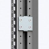
7 SIDE TO SIDE BAYING External baying brackets CCE06 Description: Mounting instructions External baying brackets are mounted on the outside hole pattern of the frame ensuring strong 3-dimensional alignment of the bayed enclosures with an auto spacer function. This method of baying enclosures also has an advantage due to its direct earthing connection between the enclosure frames. Short external baying brackets (CCEH06) are available when small partial doors and/or panels are used. Enclosure compatibility: Floor standing combinable enclosures MCS, MCD Installation: Eldon s standard side to side enclosure configurations can be bayed using six external baying brackets, three individually spaced down each vertical profile. Limitations: External baying brackets cannot be installed on stainless steel enclosures. 12 Eldon White Paper - BAYING AND LIFTING Eldon White Paper - BAYING AND LIFTING 13

8 SIDE TO SIDE BAYING Application Baying brackets should be used when an enclosure needs to be bayed next to another to extend the internal space for the installation of components, switchgear and other electrical devices. As explained, Eldon provides three different types of baying brackets/kits for baying enclosures side to side: internal baying brackets CCI, external baying brackets CCE, and internal corner baying brackets External baying brackets will be used when it is not possible to use internal baying brackets, i.e., when a separation plate is installed between bayed enclosures or between small partial doors/panels. 14 Eldon White Paper - BAYING AND LIFTING Eldon White Paper - BAYING AND LIFTING 15


9 Enclosures baying Floor standing SIDE TO SIDE BAYING Corner baying kit CCM04 Description: Internal corner baying brackets provide extra support when bayed enclosures are fully equipped and require lifting. The internal corner baying kit fixes to enclosures using the existing profile hole pattern with snap-lines. Can be installed together with the separation plate, SPD. Mounting instructions MOUNTING Enclosure compatibility: Floor standing combinable enclosures MCS, MCD, MCSS, MCDS, ECOM Installation: Eldon s standard side to side enclosure configurations are bayed using four internal corner baying brackets, one installed in each corner of the bayed enclosures along with internal baying brackets. Limitations: When the separation plate, SPD, is installed installation access is limited. It is best practice to install the corner baying brackets first. DEMOUNTING 16 Eldon White Paper - BAYING AND LIFTING Eldon White Paper - BAYING AND LIFTING 17

 External baying brackets will be used when it is not possible to use internal baying brackets, i.e., when a separation plate is installed between bayed enclosures or between small partial doors/panels.")
10 SIDE TO SIDE BAYING Application Baying brackets should be used when an enclosure needs to be bayed next to another to extend the internal space for the installation of components, switchgear and other electrical devices. As explained, Eldon provides three different types of baying brackets/kits for baying enclosures side to side: (why colon?) External baying brackets will be used when it is not possible to use internal baying brackets, i.e., when a separation plate is installed between bayed enclosures or between small partial doors/panels. 18 Eldon White Paper - BAYING AND LIFTING Eldon White Paper - BAYING AND LIFTING 19


11 SIDE TO SIDE BAYING 20 Eldon White Paper - BAYING AND LIFTING Eldon White Paper - BAYING AND LIFTING 21

 Limitations: Cannot be used in conjunction with Eldon s internal baying brackets (CCI).")
12 SIDE TO SIDE BAYING Internal separation Separation plate SPD Description: The internal space of the side to side combined enclosures can be divided using Eldon s internal separation panel, gasket and brackets. Required accessories: Separation plate brackets, CCJ12 Separation plate gasket, SPDG01 (To be used if IP43 is required) Separation plate EMI gasket, SPDEG01 (To be used if EMC shielding is required in place of SPDG01) Limitations: Cannot be used in conjunction with Eldon s internal baying brackets (CCI). External baying brackets (CCE) and/or a corner baying kit (CCM) should be used instead. 22 Eldon White Paper - BAYING AND LIFTING Eldon White Paper - BAYING AND LIFTING 23


13 SIDE TO SIDE BAYING Continuous mounting Filler plate MPF Continous mounting Wide mounting plate MPW Description: Required accessories: To maximise the amount of available mounting space on the enclosure s mounting plate when combinable enclosures are bayed, additional and alternative accessories can be used. Required accessories: Transversal sliding profile, MTS. Limitations: Mounting plates cannot be installed in the enclosure s rearmost position. N / A Limitations: Mounting plates cannot be installed in the enclosure s rearmost position. 24 Eldon White Paper - BAYING AND LIFTING Eldon White Paper - BAYING AND LIFTING 25


 Installation: Eldon s standard back to back enclosure")


 are installed (side panels are not supplied in")
14 BACK TO BACK BAYING Depth baying kit CJDN Description: Mounting instructions Depth baying kits allow combinable floor standing enclosures to be bayed back to back. The enclosures rear profiles provide the correct spacing between the enclosures. The spacing is covered by a plate provided in the baying kit. The baying kit allows for deep components to be installed along with access from both sides. Depth baying kits are delivered with a gasket as well as mounting accessories that maintain an ingress protection rating of 55. Enclosure compatibility: Floor standing combinable enclosures: MCS, MCD (MCSS, MCDS available on request) Installation: Eldon s standard back to back enclosure configurations are bayed using eight internal baying brackets, three individually spaced down each vertical profile and one in the middle of the bottom/top profiles. A gasket is placed between both enclosures to guarantee the IP rating and the configuration is finished with blanking plates to ensure a continuous smooth surface when side panels (SPM) are installed (side panels are not supplied in the depth baying kit. Limitations: Standard depth baying kit cannot be installed on stainless steel enclosures. 26 Eldon White Paper - BAYING AND LIFTING Eldon White Paper - BAYING AND LIFTING 27


15 BACK TO BACK BAYING Application Depth baying kits should be used when an enclosure needs to be bayed back to back to another to extend the depth for the installation of components, switchgear and other electrical devices. The depth baying kit can also be used if access to both sides of the enclosure solution is required. Enclosure configurations should not be transported or lifted using the depth baying kit. To transport or lift enclosures bayed back to back it is essential that they are separated first and transported as individual enclosures 28 Eldon White Paper - BAYING AND LIFTING Eldon White Paper - BAYING AND LIFTING 29


16 BACK TO BACK BAYING Internal separation Mounting plate MP Internal separation Partial mounting plate MPP Description: Required accessories: If enclosure segregation is required then a full height mounting plate, MP, with brackets can be used. Partial height mounting plates, MPP, can be installed if segregation is only required in sections of the bayed enclosures. This allows for the combination of installed deep components as well as segregation. Required accessories: Mounting plate brackets, MPA06 Click-in profile, CLPK (If heavy equipment will be assembled in the partial mounting plate) Limitations: The ingress protection rating when using Eldon s floor standing partial mounting plate to separate sections of back to back bayed enclosures has not been defined. Limitations: The ingress protection rating when using Eldon s floor standing mounting plate to separate back to back combined enclosures has not been defined. 30 Eldon White Paper - BAYING AND LIFTING Eldon White Paper - BAYING AND LIFTING 31


17 BACK TO BACK BAYING 32 Eldon White Paper - BAYING AND LIFTING Eldon White Paper - BAYING AND LIFTING 33


 Installation: An extra")


18 CORNER BAYING Depth baying kit CJDS12 Description: Mounting instructions Bayed enclosures can fit into a corner using Eldon s corner baying kit. This kind of enclosure configuration uses minimal floor space but offers maximum installation space inside the enclosures. The enclosures can be bayed together side to front or side to side. Enclosure compatibility: Floor standing combinable enclosures: MCS, MCD (MCSS, MCDS available on request) Installation: An extra enclosure is required to be placed in the corner that must have dimensions corresponding to the depths of the adjacent enclosures. Twelve internal baying brackets are needed to bay the corner enclosure to its adjacent enclosures. Profiles and gaskets are provided to ensure the ingress protection rating is maintained. Limitations: Door hinges must be facing each other on the adjacent enclosures when the corner baying kit is installed. The standard corner baying kit cannot be installed on stainless steel enclosures. 34 Eldon White Paper - BAYING AND LIFTING Eldon White Paper - BAYING AND LIFTING 35


19 CORNER BAYING Application Corner baying kits provide the perfect solution when enclosures are to be installed in environments with tight parameters and limited space. Corner baying solutions provide a lot of installation space with great accessibility, requiring less floor space than standard configurations. Corner enclosure configurations should not be transported or lifted using the depth baying kit. To lift and transport on site, it is recommended to split the enclosure configuration up into only side to side bayed enclosures. These individual enclosure configurations can then be transported normally. The enclosures can be lifted only if internal corner baying brackets (CCM) are installed. 36 Eldon White Paper - BAYING AND LIFTING Eldon White Paper - BAYING AND LIFTING 37


20 CORNER BAYING Internal separation Separation plate SPD Internal separation Side mounting plate MPS Description: Description: If enclosure segregation is required then a full height mounting plate, MP, with brackets can be used. Partial height mounting plates, MPP, can be installed if segregation is only required in sections of the bayed enclosures. This allows for the combination of installed deep components as well as segregation. Required accessories: To maximise the amount of available mounting space on the enclosure s mounting plates when combinable enclosures are bayed, additional and alternative accessories can be used. In corner enclosure configurations the way to optimise the available mounting space is to use a full height mounting place installed in the rearmost position in combination with a side mounting plate. Separation plate brackets, CCJ12 Required accessories: Separation plate gasket, SPDG01 (To be used if IP43 is required) Separation plate EMI gasket, SPDEG01 (To be used if EMC shielding is required in place of SPDG01) N / A Limitations: N / A Limitations: Cannot be used in conjunction with Eldon s internal baying brackets (CCI). External baying brackets (CCE) and/or a corner baying kit (CCM) should be used instead. 38 Eldon White Paper - BAYING AND LIFTING Eldon White Paper - BAYING AND LIFTING 39


21 CORNER BAYING 40 Eldon White Paper - BAYING AND LIFTING Eldon White Paper - BAYING AND LIFTING 41

22 42 Eldon White Paper - BAYING AND LIFTING Eldon White Paper - BAYING AND LIFTING 43


.")
23 Enclosures baying Wall mounted SIDE TO SIDE BAYING Wall mounted combining kit CK01 Description: Mounting instructions A wall mounted combining kit is to be used for baying two or more wall mounted enclosures together, side by side. This enables customers to create many more enclosure configurations than are available within Eldon s standard offering. As the combining kit is delivered in a puzzle(ok?) form, the same kit can be used on wall mounted enclosures as small as 300Hx150D up to 1200Hx400D. The combining kit maintains the enclosure s ingress protection rating. Enclosure compatibility: Wall mounted enclosures: MAS, MAD, MAP, ASR, ADR Installation: Machining will initially be required to cut the side out of the enclosure to the required size before installing the combining kit. Four bolts will be installed in each corner of the cutout (two additional bolts will be required for larger enclosures). The gasket should be removed from its adhesive backing and placed on the side of the enclosure to be bayed. The enclosures should be placed together and the bolts tightened to compress the gasket. Limitations: Combining gasket should not be used to combine multiple stainless steel enclosures with integrated rainhoods together. 44 Eldon White Paper - BAYING AND LIFTING Eldon White Paper - BAYING AND LIFTING 45

24 Enclosures baying Wall mounted SIDE TO SIDE BAYING Application Wall mounted combining kits should be used to extend the internal space in width, in wall mounted enclosures for the installation of components, switchgear and other electrical devices. This also allows for components to be segregated permitting different levels of access while they maintain communication with each other. It is the perfect solution if a high ingress protection rating is required that is over and above Eldon s double door wall mounted enclosures. Wall mounted side to side combined enclosures can be transported without the need for additional accessories. To lift the combined enclosures, Eldon s wall mounted lifting eyes need to be installed, two per enclosure (AL9301). 46 Eldon White Paper - BAYING AND LIFTING Eldon White Paper - BAYING AND LIFTING 47


25 Enclosures baying Wall mounted SIDE TO SIDE BAYING 48 Eldon White Paper - BAYING AND LIFTING Eldon White Paper - BAYING AND LIFTING 49

 that ensure a robust enclosure combination.")

26 Enclosures baying Wall mounted TOP TO BOTTOM BAYING Gland plate combining gaskets AGC Description: Mounting instructions To be used when a vertical wall mounted enclosure combination is required. Combining gaskets are to be used to bay gland plate openings together. Gland plate combining gaskets consist of a polyethylene gasket foam that is sized for the wall mounted enclosure that requires combining. This maintains an ingress protection rating equivalent to that of the enclosure. The kit consists of two gaskets and mounting materials (i.e., screws, washers and nuts) that ensure a robust enclosure combination. Enclosure compatibility: Wall mounted enclosures: MAS, MAD, MAP, Installation: Rotate the enclosure that will be installed on the bottom 180 degrees (not applicable for MAP). Install the gasket between the two enclosures to be combined, ensuring both of the gland plates are aligned. To secure the enclosures together install the supplied bolts, washers, nuts and protective gaps. Wall mounted enclosures come with different sized gland plates depending on the dimensions of the enclosure. Ensure the gland plate sizes of the two enclosures match before combining. Limitations: Gland plate combining gasket can only be used with mild steel wall mounted enclosures. 50 Eldon White Paper - BAYING AND LIFTING Eldon White Paper - BAYING AND LIFTING 51

27 Enclosures baying Wall mounted TOP TO BOTTOM BAYING Application Wall mounted gland plate combining kits should be used to extend the internal space, in height, of wall mounted enclosures for the installation of components, switchgear and other electrical devices. The gland plate combining gasket is the perfect solution if components need to be separated, e.g., power and control equipment. Segregating components means that access is gained through different enclosure doors and hence different access rights can be applied while the components maintain internal communication. Wall mounted top to bottom combined enclosures can be transported without the need for additional accessories. To lift the bayed enclosures, Eldon s wall mounted lifting eyes will be required (AL9301). 52 Eldon White Paper - BAYING AND LIFTING Eldon White Paper - BAYING AND LIFTING 53


28 Enclosures baying Wall mounted TOP TO BOTTOM BAYING 54 Eldon White Paper - BAYING AND LIFTING Eldon White Paper - BAYING AND LIFTING 55

29 Enclosures baying Wall mounted 56 Eldon White Paper - BAYING AND LIFTING Eldon White Paper - BAYING AND LIFTING 57


30 ENCLOSURES LIFTING This section of the white paper covers all the ways to lift an Eldon enclosure, which accessories should be used, the effects different enclosure configurations can have, and the permissible loads allowed in Eldon s enclosures during these safety critical transportation operations. Crane lifting angles Following the correct methods when transporting enclosures is critical to ensure that the enclosure s integrity is maintained and that the components installed inside are safe, secure and protected from the installation environment. Lifting operations can be performed by a crane, forklift truck or people (depending on the load). This section covers which accessories should be used to carry out lifting operations, how the accessories should be installed and how these factors impact different enclosure configurations. 60 o angle A crane can lift floor standing enclosures by attaching to the lifting eye bolts, creating an angle of 60 degrees to the enclosure s roof plate. The enclosure lifting methods explained within this technical document will be suitable for cranage only. 90 o angle A crane can lift floor standing enclosures by attaching to the lifting eye bolts, creating an angle of 90 degrees to the enclosure s roof plate. Cable angles of 90 o to the enclosure s roof plate will support the largest loads when lifted. 90 o angle A crane can lift enclosures by attaching to the lifting eye bolts, creating an angle of 90 degrees to the enclosure s toop. 58 Eldon White Paper - BAYING AND LIFTING Eldon White Paper - BAYING AND LIFTING 59
 Description: Mounting instructions Install Eldon s lifting eyes")


31 Enclosures lifting Floor standing STAND ALONE ENCLOSURES Lifting eye bolts LE9304(SS) Description: Mounting instructions Install Eldon s lifting eyes on floor standing enclosures if crane transportation is required. Individually transported enclosures will require four lifting eyes to be fitted, one in each corner. Lifting eyes come with M12 threads and comply with DIN 580 lifting requirements. Enclosure compatibility: Floor standing combinable enclosures: MCS, MCD, MCSS, MCDS, MKS, MKD, EKS, EKD, EKSS, EKDS For stainless steel enclosures use lifting eyes with the suffix SS Installation: To install Eldon s lifting eyes remove the caps or bolts from each corner of the enclosure s roof plate and thread the lifting eyes into the threaded frame or blind rivet nuts that are already installed. Limitations: N / A. 60 Eldon White Paper - BAYING AND LIFTING Eldon White Paper - BAYING AND LIFTING 61

32 Enclosures lifting Floor standing STAND ALONE ENCLOSURES Lifting capacity Individual floor standing enclosures can be transported by crane safely using the enclosure s lifting eyes. The load installed inside the enclosure is systematically distributed allowing for a smooth transit. Cable lifting angle (o) Permissible load (N) Eldon White Paper - BAYING AND LIFTING Eldon White Paper - BAYING AND LIFTING 63


33 Enclosures lifting Floor standing STAND ALONE ENCLOSURES Lifting kit MCUK04 Description: Mounting instructions Eldon s lifting kit is to be installed and used on enclosures that are fitted with top cabling frames. The lifting kit fits directly into the enclosure s frame, therefore during lifting operations no stress is applied to the cabling frame, it is directed straight into the enclosure Enclosure compatibility: Floor standing combinable enclosures: MCS, MCD, Installation: To install Eldon s lifting kit ensure there are no bolts or caps installed on the top of the cable frame. Install the lifting kit spindles through each hole of the cable frame and thread into the enclosure s blind rivet nuts. Limitations: Once installed the lifting kit can only be lifted at an angle of 90o from the enclosure s roof plate. The lifting kit is only suitable for cabling frames that are 200mm high. 64 Eldon White Paper - BAYING AND LIFTING Eldon White Paper - BAYING AND LIFTING 65

34 Enclosures lifting Floor standing STAND ALONE ENCLOSURES Lifting capacity Individual floor standing enclosures with a top cabling frame installed can be transported by crane safely using the enclosure s lifting kit. The load installed inside the enclosure is systematically distributed allowing for smooth transit. Cable lifting angle (o) Permissible load (N) Eldon White Paper - BAYING AND LIFTING Eldon White Paper - BAYING AND LIFTING 67

35 Enclosures lifting Floor standing SIDE TO SIDE ENCLOSURES Lifting eye bolts LE9304 (SS) Description: Mounting instructions Install Eldon s lifting eyes on floor standing enclosures if crane transportation is required. Two side to side bayed enclosures will require four lifting eyes to be fitted, one in each corner of the combined unit. Lifting eyes come with M12 threads and comply with DIN 580 lifting requirements. Enclosure compatibility: Floor standing combinable enclosures: MCS, MCD, MCSS, MCDS, For stainless steel enclosures use lifting eyes with the suffix SS Installation: To install Eldon s lifting eyes remove the caps or bolts from each corner of the enclosure s roof plate and thread the lifting eyes into the threaded frame or blind rivet nuts that are already installed. The corner baying kit, CCM04, will be required for side to side bayed enclosures during transportation and lifting operations. Limitations: N / A. 68 Eldon White Paper - BAYING AND LIFTING Eldon White Paper - BAYING AND LIFTING 69

 Permissible load (N) 60 3200 in each enclosure 90 5100 in each enclosure 70 Eldon White Paper - BAYING AND")
36 Enclosures lifting Floor standing SIDE TO SIDE ENCLOSURES Lifting capacity If required, Eldon s lifting eyes can also be installed to lift side to side bayed enclosures for transportation purposes and to ensure that the enclosures can be installed regardless of the location. Lifting eyes can be lifted at an angle of either 60 or 90 degrees from the horizontal. Cable lifting angle (o) Permissible load (N) in each enclosure in each enclosure 70 Eldon White Paper - BAYING AND LIFTING Eldon White Paper - BAYING AND LIFTING 71


37 Enclosures lifting Floor standing SIDE TO SIDE ENCLOSURES Lifting device LC Description: Mounting instructions Install Eldon s lifting device on floor standing enclosures for optimal weight distribution when lifting bayed enclosures. The lifting device only needs to be installed on the sides where the enclosures are bayed. Enclosure compatibility: Floor standing combinable enclosures: MCS, MCD (MCSS, MCDS available on request) Installation: To install Eldon s lifting device ensure there are no bolts or caps already fitted on the enclosure s roof plate. Bay the floor standing enclosures together using Eldon s baying brackets. Install a lifting device on either side of the two or more enclosures that will be bayed and secure using the M12 bolts supplied. The corner baying kit, CCM04, will be required for side to side bayed enclosures during transportation and lifting operations. Limitations: The lifting device is made from zinc plated steel and if mounted on stainless steel enclosures it must be removed and replaced with bolts or caps afterwards. 72 Eldon White Paper - BAYING AND LIFTING Eldon White Paper - BAYING AND LIFTING 73


38 Enclosures lifting Floor standing SIDE TO SIDE ENCLOSURES Lifting capacity Lifting capacity Two floor standing enclosures bayed side by side can be transported by crane safely using the applicable lifting accessories. The load installed inside the enclosure is systematically distributed allowing for smooth transit. The lifting accessory required for side to side bayed enclosures is Eldon s lifting device. It is also possible to lift three enclosures bayed side to side using Eldon s lifting device. The lifting device ensures that the weight installed inside the enclosures is equally distributed resulting in smooth transit. The permissible load for each enclosure will depend on the enclosure s position within the configuration. Cable lifting angle (o) Permissible load (N) Enclosure position Permissible load (N) Eldon White Paper - BAYING AND LIFTING Eldon White Paper - BAYING AND LIFTING 75


39 Enclosures lifting Floor standing BACK TO BACK BAYED ENCLOSURES Back to back bayed enclosures should be separated before being transported and/or lifted. The required accessories and permissible loads are covered under the standalone enclosure section. 76 Eldon White Paper - BAYING AND LIFTING Eldon White Paper - BAYING AND LIFTING 77


40 Enclosures lifting Floor standing CORNERED BAYED ENCLOSURES Corner bayed enclosures should be separated before being transported and/or lifted. The required accessories and permissible loads are covered under the standalone and side to side installation sections. 78 Eldon White Paper - BAYING AND LIFTING Eldon White Paper - BAYING AND LIFTING 79


41 Enclosures lifting Wall mounted SINGLE ENCLOSURE Lifting eyes AL9301 Description: Mounting instructions Install Eldon s lifting eyes on wall mounted enclosures if crane transportation is required. Wall mounted enclosures will only require two lifting eyes and should be installed as per Eldon s mounting instructions. Enclosure compatibility: Wall mounted enclosures: MAS, MAD, ASR, ADR Installation: To install Eldon s lifting eyes, machine two holes in the rear two corners as per the mounting instructions. Insert the lifting eyes through the machined holes and secure using the reinforcement brackets, washers and nuts provided. Reinforcement brackets are supplied to ensure that the enclosure is supported adequately when lifted Limitations: The lifting eyes are made from zinc plated steel and if mounted on stainless steel enclosures they must be removed afterwards and replaced with bolts or caps. 80 Eldon White Paper - BAYING AND LIFTING Eldon White Paper - BAYING AND LIFTING 81

 Permissible load (N) 45 2400 60 3200 90 4000 82 Eldon White Paper - BAYING AND")
42 Enclosures lifting Wall mounted SINGLE ENCLOSURE Lifting capacity Individual wall mounted enclosures can be transported by crane safely using the enclosure s lifting eyes. The load that is installed inside the enclosure is systematically distributed allowing for smooth transit. Cable lifting angle (o) Permissible load (N) Eldon White Paper - BAYING AND LIFTING Eldon White Paper - BAYING AND LIFTING 83
43 Baying and lifting white papers Version 1.0 EN, Eldon Holding AB. All rights reserved.
enclosures to ATEX and enclosures for special custom design (EEx p and NEMA cabinets)
") enclosures to ATEX and enclosures for special custom design (EEx p and NEMA cabinets) Stainless steel and plastic enclosures for use in potentially explosive environments R Rittal system partners Perfect
enclosures to ATEX and enclosures for special custom design (EEx p and NEMA cabinets) Stainless steel and plastic enclosures for use in potentially explosive environments R Rittal system partners Perfect
enclosures to ATEX and enclosures for special custom design (EEx p and NEMA cabinets)
") lri030784900.eps lri031083400.eps enclosures to ATEX and enclosures for special custom design (EEx p and NEMA cabinets) fri040466500.eps Stainless steel and plastic enclosures for use in potentially explosive
lri030784900.eps lri031083400.eps enclosures to ATEX and enclosures for special custom design (EEx p and NEMA cabinets) fri040466500.eps Stainless steel and plastic enclosures for use in potentially explosive
ARCA cabinet NEW. High performance polycarbonate cabinet. Protection in demanding environments
 ARCA cabinet NEW High performance polycarbonate cabinet Protection in demanding environments NEW Fibox ARCA Fibox ARCA non corrosive electrical cabinets for use in extremely harsh and demanding environments
IECEx Certificate of Conformity Annexe
 for Certificate No.: IECEx TSA 09.004X Issue No.: 1 Equipment description pertaining to Issue 0 of this Certificate: A range of electrical power distribution, control, protection and monitoring equipment
XTS-Impact. XTS-Terminal (hold)
") XTS-Impact The XTS-Impact is used to support the XTS-Linked system, as a standalone anchorage point and as an anchorage point in horizontal temporary lifeline systems. The anchorage point is tested according
XTS-Impact The XTS-Impact is used to support the XTS-Linked system, as a standalone anchorage point and as an anchorage point in horizontal temporary lifeline systems. The anchorage point is tested according
CFSW. Hinges with built-in safety multiple switch
 CFSW. Hinges with built-in safety multiple switch ELESA Original design Elesa Standards Main dimensions Fitting Weight Code Description L B f ±0.2 f 1 ±0.2 H h 1 h 2 d 3 d 4 C [Nm]# g 426601 CFSW.110-6-2NO+2NC-C-A
INSTALLATION INSTRUCTIONS PUSH BAR PULLMAN PANIC BOLT DEVICE TO EN 1125 : 2008
 INSTALLATION INSTRUCTIONS PUSH BAR PULLMAN PANIC BOLT DEVICE TO EN 1125 : 2008 0376/448/00 ISSUE 01 EMERGENCY PUSH PAD PULLMAN BOLT DEVICE TO EN 179 : 2008 1000mm MAXIMUM CLEAR OPENING HEIGHT WITH PUSH
High-performance submersible pressure transmitter For level measurement Model LH-10
 Electronic pressure measurement High-performance submersible pressure transmitter For level measurement Model LH-10 WIKA data sheet PE 81.09 Applications Level measurement in rivers and lakes Deep well
Technical information for hinges
 451 452 Technical information for hinges In the tables on the following pages are listed a large range of hinge variations. Many more variations are possible if hinges with guide tabs are required i.e.
Extension Platform. Base Platform. Crossover. Exit railing. Exit Railing
 Base Platform Galvanized With metal grate and two brackets Railing on the long side and a face side Extension Platform Galvanized With metal grate and one bracket Railing on the long side with rail connection
Pneumatic spool valve islands
 Pneumatic spool valve islands P7.GB.R MEGA SPOOL VALVE ISLANDS MEGA pneumatic spool valve islands offer maximum performance along with flexibility, easy installation and simple operation. Due to their
DM01. Please visit our website: Battery Powered Precision Digital Gauge. Stainless Steel Sensor. class 0.05
 DM0 Battery Powered Stainless Steel Sensor class 0.05 Nominal pressure from 0 00 mbar up to 0... 00 bar Special characteristics modular sensor concept data logger graphic display stainless steel housing
February Cable glands For general industry and hazardous areas
 February 2017 Cable glands For general industry and hazardous areas Introduction When safety matters, there is only one choice The Nicote and Kopex range of cable glands come to ABB through the acquisition
IDL01. Battery Powered Precision Digital Gauge for Leak Testing. Stainless Steel Sensor. class 0.05
 IDL0 Battery Powered Precision Digital Gauge for Leak Testing Stainless Steel Sensor class 0.05 Nominal pressure from 0 00 mbar up to 0... 00 bar Special characteristics modular sensor concept data logger
steel wire cable tray system accessories
 accessories Marco Cable Management has further enhanced its reputation, by the continued growth in innovative products and supportive accessories. Marco has also invested heavily in new state of the art
F13.11 PARALLEL HINGES F13 PROJECT-OUT WINDOWS AND TOP HUNG WINDOWS
 F13 PROJECT-OUT WINDOWS AND TOP HUNG WINDOWS F13.11 01.06.2018 Waregemstraat 5-9870 Zulte - Belgium - T. +32 9 388 88 81 - F. +32 9 388 88 21 - commercial@sobinco.com - www.sobinco.com CONTENTS 1. General...F13.11.03
High-performance submersible pressure transmitter For level measurement Model LH-10
 Electronic pressure measurement High-performance submersible pressure transmitter For level measurement Model LH-10 WIKA data sheet PE 81.09 Applications Level measurement in rivers and lakes Deep well
Advantage Lockers & Bike
 Advantage Lockers & Bike Advantage Bike Racks & Lockers Inc. is the #1 supplier of Storage Lockers and Bike Racks to the Lower Mainland s residential construction industry. With 25+ years of experience
2-1- Shipping Receiving Lifting Location on Site Installation Stages 6
 NEUTRAL GROUNDING RESISTORS INSTALLATION, OPERATION & MAINTENANCE MANUAL Contents 1- SAFETY INSTRUCTIONS... 3 1-1- Compliance with Instructions in this Manual. 3 1-2- Guidance Notes Installation.... 3
Data sheet Pressure switch type CS December 2001 DKACT.PD.P10.A B1119
 Pressure switch type CS December 2001 DKACT.PD.P10.A2.02 520B1119 Introduction Pressure switch type CS is part of the Danfoss pressure control range. All CS pressure switches have a built-in pressure-operated,
CFSW. Hinges with built-in safety multiple switch
 CFSW. Hinges with built-in safety multiple switch ELESA Original design technical informations Material - Hinge body: self-extinguish high-rigidity SUPER-technopolymer, black colour. Resistant to solvents,
Medium Voltage Switchgear. Installation Manual for Pressure Relief Ducts
 Uniswitch Medium Voltage Switchgear Installation Manual for Pressure Relief Ducts TABLE OF CONTENTS 1 Summary... 1 2 Transportation and storage... 2 2.1 Condition on delivery... 2 2.2 Unpacking at installation
Installation Instructions MODEL VSTI-A020 Tank Indicator Installation Model: VSTI-A020, Stainless Reverse Read System Versa Steel Inc. Guide Cables No
 Tank Indicator Installation Model: VSTI-A020, Stainless Reverse Read System Guide Cables No Guide Cables 1 August 4, 2011 Assembly Instructions: (Shown with a 2 board, 12 ft kit) ITEM NO. PART NUMBER DESCRIPTION
Datasheet liniled Handrail 48.3 V1017 IK10 IP68. F RoHS IP40/IP65 FROST CLEANING AGENTS RESISTANT UV RESISTANT
 Datasheet liniled Handrail 4 V1017 F RoHS IP40/IP65 IP68 IK10 AISI 316 UV RESISTANT FROST CLEANING AGENTS RESISTANT Handrail 4 Product information Technical specifications Product specifcations Required
3M InCa Individual Cross-Connection Cabinets
 3M InCa Individual Cross-Connection Cabinets InCa 7/14 InCa 7/12 InCa 7/10 InCa 7/8 InCa 8/14 InCa 8/12 InCa 8/10 InCa 8/8 InCa 10/14 InCa 10/12 InCa 10/10 InCa 10/8 Series 7 Series 8 Series 10 87 The
DM01. Battery Powered Precision Digital Gauge. Stainless Steel Sensor. class 0.05
 Battery Powered Stainless Steel Sensor class 0.05 Nominal pressure from 0 00 mbar up to 0... 00 bar Special characteristics modular sensor concept data logger graphic display stainless steel housing Ø
ETd 04. Battery Powered Precision Digital Gauge. Stainless Steel Sensor. Type: ETd 04. class 0.05
 Battery Powered Stainless Steel Sensor class 0.05 Nominal pressure from 0 100 mbar up to 0... 400 bar Special characteristics modular sensor concept data logger graphic display stainless steel housing
MSA Latchways Ladder System
 Systems overview 1 of 13 Important information Individuals or organisations carrying out the installation of a MSA Latchways ladder fall protection system shall read, understand and follow these instructions
SET OF EUROLEAGUE BACKSTOP UNITS (Reference PK120)
") SET OF EUROLEAGUE BACKSTOP UNITS (Reference PK120) DESCRIPTION The EUROLEAGUE backstop unit is mainly designed for multi-sports pavilions and installations where the highest-level basketball competitions
SET OF EUROLEAGUE BACKSTOP UNITS (Reference PK120) DESCRIPTION The EUROLEAGUE backstop unit is mainly designed for multi-sports pavilions and installations where the highest-level basketball competitions
ORNAMENTAL CANTILEVER GATE INSTRUCTIONS
 U.S.A. Patent Number 5,36,83 ORNAMENTAL CANTILEVER GATE INSTRUCTIONS *NOTICE: Ornamental Cantilever Gates are supplied with rolls of 2 mesh safety screening in sufficient quantities to cover the entire
Shifting Lever. RAPIDFIRE Plus 11-speed
 (English) DM-SL0005-04 Shifting Lever Dealer's Manual RAPIDFIRE Plus 11-speed MTB XTR SL-M9000 DEORE XT SL-M8000 CONTENTS IMPORTANT NOTICE... 3 TO ENSURE SAFETY... 4 LIST OF TOOLS TO BE USED... 7 INSTALLATION...
Further technical information is available on
 1 of 5 Manufacture address : Bartec Technor AS Dusavikveien 39 4007 Stavanger Norway Further technical information is available on www.bartec-technor.no Note on instructions When working in hazardous areas,
steel wire cable tray system accessories
 Marco Cable Management has further enhanced its reputation, by the continued growth in innovative products and supportive. Marco has also invested heavily in new state of the art equipment to enhance its
AVK SERIES 601, 602, 603 & 605 UNIVERSAL COUPLINGS, ADAPTORS & END CAPS INSTALLATION, OPERATION & MAINTENANCE MANUAL
 Instruction for use Thank you for selecting an AVK product. With correct use, the product is guaranteed to deliver a long and reliable service. This manual has been prepared to assist you with the installation,
Pressure switch Type BCP
 Data sheet Pressure switch Type BCP The BCP type is a series of dedicated switches for safety and monitoring of steam and hot water boilers. The BCP incorporates a single-pole changeover microswitch where
8MAY15 US RACK, Inc Falcon Drive, Madera, CA
 8MAY15 US RACK, Inc. - 2850 Falcon Drive, Madera, CA 93637-559-661-3050 INSTRUCTIONS for Bedrail-mounted MOTORCYCLE RACK, Model 2001-4TRA WARNING: Do NOT attempt to install or use this rack without following
ABTQ-110 rev 00 (Last review: 28 Aug 12) INSTALLATION, OPERATION & MAINTENANCE INSTRUCTIONS FOR ABTECH S RANGE ENCLOSURES IECEx SIR U SERIAL No
 INSTALLATION, OPERATION & MAINTENANCE INSTRUCTIONS FOR ABTECH S RANGE ENCLOSURES IECEx SIR U SERIAL No") ABTQ-110 rev 00 (Last review: 28 Aug 12) INSTALLATION, OPERATION & MAINTENANCE INSTRUCTIONS FOR ABTECH S RANGE ENCLOSURES IECEx SIR 05.0046U SERIAL No 20 TYPE SX Ex e II C Gb Ex tb IIIC Db IP6* IECEx SIR
ABTQ-110 rev 00 (Last review: 28 Aug 12) INSTALLATION, OPERATION & MAINTENANCE INSTRUCTIONS FOR ABTECH S RANGE ENCLOSURES IECEx SIR 05.0046U SERIAL No 20 TYPE SX Ex e II C Gb Ex tb IIIC Db IP6* IECEx SIR
RATCHET RELEASE SHACKLE
 RATCHET RELEASE SHACKLE INNOVATIVE PILING EQUIPMENT HYDRAULIC PILING HAMMERS EURO RATCHET RELEASE SHACKLE FOR STEEL ERECTION OPERATORS INSTRUCTIONS & SPARE PARTS LIST EXCAVATOR MOUNTED VIBRATORS EXCAVATOR
ROLLER SLIDE BALL BEARING
 ROLLER SLIDE BALL BEARING ROLLER SLIDE SYSTEM BALL BEARING SLIDE SYSTEM Standard slides and ball bearing slides offering a variety of top quality movement systems. www.grassusa.com Roller slides: Tried-and-tested
Conductor Bushings Series 8174
 > Current lead-in for Ex d enclosures > 1 to 72 conductors combined in one current lead-in > Series screw-in plug-in > For voltages up to max. 1 V > For size conductor up to 7 mm 2 www.stahl.de 3163E The
User Manual. User Manual
 Thank you Thank you for buying RGK We hope the product and service you have received has met your expectations. Please take time to read the instructions contained within, to familiarise yourself with
AREA VALVE SERVICE UNITS
 AREA VALVE SERVICE UNITS. Unit 8, McKenzie Industrial Park, Tel No.: 44 (0) 161 428 7200 Bird Hall Lane, Fax No.: 44 (0) 161 428 7010 Stockport, Email: info@p3-phoenix.com U.K., SK3 0SB www.p3-phoenix.com
Datasheet liniled Handrail 42.4 V1017 IK10. F RoHS FROST CLEANING AGENTS RESISTANT UV RESISTANT
 Datasheet liniled Handrail 42.4 V1017 F RoHS IP40 IP68 IK10 AISI 316 UV RESISTANT FROST CLEANING AGENTS RESISTANT Handrail 42.4 Product information Technical specifications Product specifcations Required
Floor Mount Socket. T: +44 (0) F: +44 (0)
 F: +44 (0)") G-Davit : Floor Mount Socket USER INSTRUCTION MANUAL A davit socket for installation bolted to a high strength flooring material. Suitable for both fall arrest use and lifting. EN795 Class B, PPE Anchor
G-Davit : Floor Mount Socket USER INSTRUCTION MANUAL A davit socket for installation bolted to a high strength flooring material. Suitable for both fall arrest use and lifting. EN795 Class B, PPE Anchor
SERIES 2 RAMP OWNER S MANUAL TOOLS REQUIRED: BEFORE YOU BEGIN... Read and understand these instructions before beginning a ramp setup.
 SERIES 2 RAMP OWNER S MANUAL BEFORE YOU BEGIN... Read and understand these instructions before beginning a ramp setup. Use caution and care for your back when lifting, pushing, pulling, folding or unfolding
Model 6810A Dual Lane Scoreboard Owner s Manual Rev B
 RACEAMERICA T i m i n g S y s t e m s Model 6810A Dual Lane Scoreboard Owner s Manual Rev B RACEAMERICA, Inc. P.O. Box 3469 Santa Clara, CA 95055-3469 (408) 988-6188 http://www.raceamerica.com info@raceamerica.com
Pressure Dump Valve Service Kit for Series 3000 Units
 Instruction Sheet Pressure Dump Valve Service Kit for Series 000 Units. Overview The Nordson pressure dump valve is used to relieve hydraulic pressure instantly in Series 00, 400, 500, and 700 applicator
Installation and Training Manual
 AirForce1 Tower Kit Installation and Training Manual FuturEnergy Limited Ettington Park Business Centre Stratford upon Avon CV37 8BT +44 (0)1789 451070 Table of Contents Safety Notes... 3 Parts Supplied
Pressure switches for air and water CS
 Data sheet Pressure switches for air and water CS CS pressure switches have a built-in pressure operated, three-pole switch. The contact position of which depends on the pressure in the connector and the
Components for air preparation and pressure adjustment. OUT port position ( ) connected Rear side. of IN port. Air tank. directly.
 connected Rear side. of IN port. Air tank. directly.") Components preparation and pressure adjustment ABP Overview ABP is a component that enables boosting by s only up to twice primary pressure (.0MPa max.) in combination with using air tank but not using
Components preparation and pressure adjustment ABP Overview ABP is a component that enables boosting by s only up to twice primary pressure (.0MPa max.) in combination with using air tank but not using
Sensor for Air Bubble Detection at Liquid Filled Tubes. SONOCHECK Type ABD06.xx. Operating Manual
 Sensor for Air Bubble Detection at Liquid Filled Tubes SONOCHECK Type ABD06.xx Operating Manual Manufacturer: Model: Type: SONOTEC Ultraschallsensorik Halle GmbH Air Bubble Detector ABD06.xx SONOTEC Ultraschallsensorik
PRESSURE COMPARATOR 10000PSI 700bar. Operator Instructions CRYSTAL. engineering corporation
 PRESSURE COMPARATOR GauGeCaLXP 10000PSI 700bar Operator Instructions Page 2 GaugeCalXP Operator Instructions PRESSURE is Our BUSINESS Introduction Thank you for purchasing a GaugeCalXP Pressure tor from
ASSEMBLY INSTRUCTIONS S O L O N STANDARD MODULES
 ASSEMBLY INSTRUCTIONS S O L O N STANDARD MODULES SOLON Blue 230/07 SOLON Black 230/07 (01, 02) SOLON Blue 220/03 (01, 07) SOLON Black 280/10 SOLON Black 300/10 SOLON P220/6+/07 SOLON M230/6+/07 (01) SOLON
A soft sealed atmospheric safety valve with large flow capacity and soft seat tightness for steam condenser and turbine applications
 SAPAG A soft sealed atmospheric safety valve with large flow capacity and soft seat tightness for steam condenser and turbine applications Features The Sapag Series 1100 steam safety valve is used for
1 Overview. Pressure Measurement Single-range transmitters for general applications. 1/22 Siemens FI
 Siemens AG 06 SITRANS LH00 Transmitter for hydrostatic level Overview Function U const. p U I EM The pressure transmitter SITRANS LH00 is a submersible sensor for hydrostatic level measurement. The pressure
SPM INDOOR TRAINING CYCLE ASSEMBLY MANUAL MODEL: SPM
 SPM INDOOR TRAINING CYCLE ASSEMBLY MANUAL MODEL: SPM Questions? As a quality exercise equipment supplier we are committed to your complete satisfaction. If you have questions, or find missing or damaged
MSA Confined Space Entry Equipment
 MSA Confined Space Entry Equipment Because every life has a purpose... MSA Confined Space Entry Equipment MSA XTIRPA Manhole Guard System Use for confined space vertical entry and fall protection when
Mounting and Operating Instructions EB 8546 EN. Supply Pressure Regulator Type Fig. 1 Supply pressure regulators
 Supply Pressure Regulator Type 4708 Type 4708-5352 on Type 3730 Positioner Type 4708-52 with filter receptacle Type 4708-6252 on Type 3372 ctuator Fig. Supply pressure regulators Mounting and Operating
Data Distribution Cabinets. Exclusive CD edition March 2006
 Exclusive CD edition March 2006 Introduction: The development of distribution cabinets is the practical reply from KRONE to the ever increasing demands on the data, telephone, and network technology. Cost-effective,
Metham Aviation Design Limited, Station Approach, Four Marks, Alton. Hants. GU34 5HN Tel +44 (0) Fax +44 (0)
 Fax +44 (0)") Contents Page General Information 1 Items Supplied 1 Variants 1 Compatibility with other products 1 Fitting a Housing 2 Mounting a Bowler 3 Safety Precautions 4 Control Connections 5 Setting up a Bowler
Contents Page General Information 1 Items Supplied 1 Variants 1 Compatibility with other products 1 Fitting a Housing 2 Mounting a Bowler 3 Safety Precautions 4 Control Connections 5 Setting up a Bowler
Rocky Mountain Instinct / Pipeline Alloy Frame Assembly Guide. Date: April 7, 2017
 Rocky Mountain Instinct / Pipeline Alloy Frame Assembly Guide Date: April 7, 2017 1 Table of Contents Front Triangle Preparation... 4 Parts Needed... 4 Instructions... 4 Chain Stay Preparation... 6 Parts
TRAVSMART permanent single-cable horizontal lifeline system
 The Travsmart single-line system provides a smooth travel. It allows the traveler to move freely over the intermediate anchors, minimizing wear and eliminating user assistance. The user s hands remain
Mounting and Operating Instructions EB 3007 EN. Self-operated Pressure Regulators. Differential Pressure Regulators (opening) Type Type 42-25
 Type Type 42-25") Self-operated Pressure Regulators Differential Pressure Regulators (opening) Type 42-20 Type 42-25 Type 42-20 Differential Pressure Regulator Type 42-25 Differential Pressure Regulator Mounting and Operating
Self-operated Pressure Regulators Differential Pressure Regulators (opening) Type 42-20 Type 42-25 Type 42-20 Differential Pressure Regulator Type 42-25 Differential Pressure Regulator Mounting and Operating
Agilent 1220 Infinity II LC Mobile Upgrade Kit
 Agilent 1220 Infinity II LC Mobile Upgrade Kit Note 1220 Infinity II LC Mobile Upgrade Kit This note describes the procedures to install an Mobile Upgrade kit to an existing Agilent 1220 Infinity II LC.
Vibration isolation system 1VIS10W. User manual
 Vibration isolation system 1VIS10W User manual Standa 2014 Table of contents 1. General information 3 1.1. Introduction 3 1.1.1. Safety 5 1.2. Location of the table 5 1.3. Air supply requirements 5 2.
LMP 307. Stainless Steel Probe. Stainless Steel Sensor. accuracy according to IEC 60770: standard: 0.35 % FSO option: 0.25 % / 0.
 LMP 07 Stainless Steel Sensor accuracy according to IEC 60770: standard: 0.5 % FSO option: 0.5 % / 0. % FSO Nominal pressure from 0... mho up to 0... 50 mho Output signals -wire: 4... 0 ma -wire: 0...
Specialists in HTM Medical Gas Pipeline Equipment AVSU/Module Operating and Maintenance Instructions
 The Area Value Service Units and Module format (AVSU) provide a local gas isolation facility for use during normal installation and maintenance or in the event of an emergency. They are built in accordance
Tern Rapid Transit Rack
 Tern Rapid Transit Rack Rapid Transit Rack Specifications Cargo load capacity: 25kg (55.1 lb) Compatibility Fits most Tern Link, Verge and Vektron models. Trolley Handle not compatible with certain models.
ST Shimano Total Integration. Technical Service Instructions. General Safety Information SI-6CT0B
 Technical Service Instructions SI-6CT0B t ST-4400 Shimano Total Integration Shimano Total Integration Features The Shimano Total Integration TIAGRA series features a dual action control lever which actuates
1 Overview. Pressure Measurement Single-range transmitters for general applications. 1/22 Siemens FI US Edition
 Siemens AG 07 SITRANS LH00 Transmitter for hydrostatic level Overview Function U const. p U I EM The pressure transmitter SITRANS LH00 is a submersible sensor for hydrostatic level measurement. The pressure
1 Overview. Pressure Measurement Transmitters for basic requirements. 1/16 Siemens FI SITRANS P220 for gauge pressure
 Siemens AG 204 Overview The pressure transmitter SITRANS P220 measures the gauge pressure of liquids, gases and vapors. Stainless steel measuring cell, fully welded Measuring ranges 2.5 to 600 bar (36.3
PCB accessories. PCB handle C. PCB retainer C. Order Information. Note. Order Information
 PCB accessories PCB handle C PCB accessoriesmain CataloguePart number in bold face type: ready for despatch within 2 working dayspart number in normal type: ready for despatch within 0 working days For
MDM Accessories
 Accessories General Hardwares are the screwlock assemblies or the brackets used for the mounting of connectors on panels or PC, or for the fixing of plugs and receptacles. They are not fixed on the connectors
VERSA BIKE RACK INSTRUCTIONS
 VERSA BIKE RACK INSTRUCTIONS Models #8, 8 Important This rack is designed for use with a or. receiver hitch. The rack is designed to hold a maximum of two bicycles. Do not use it for anything other than
MPG-plus. Application example. Pneumatic 2-Finger Parallel Gripper Gripper for small components. Gripping force 38 N 175 N. Sizes
 MPG-plus Sizes 25 40 Weight 0.06 kg 0.24 kg Gripping force 38 N 175 N Stroke per finger 3 mm 6 mm Workpiece weight 0.19 kg 0.7 kg Application example Pneumatically driven, dual-axis pick-and-place machine
The evolution of the Ex-proof flame path
 April 2017 The evolution of the Ex-proof flame path As written in previous dissertation, the most critical part of a flameproof enclosure 'Ex d' is the flame path. Although the Standards are divided into
World Area Differences Technical Information
 World Area Differences Technical Information DMISC2047X02 This document is to give more information about the following: Porting & Threads Cleaning Procedures Conversion Tables PORTING & THREADS NPT (National
Pressure Measurement Single-range transmitters for general applications
 Siemens AG 07 Overview Function U const. p U I EM Sensor Connection for auxiliary power supply Vent pipe with humidity filter Protective conductor connection/ Equipotential bonding Diaphragm The pressure
DICTATOR "DIREKT" Gate Closer
 DICTATOR "DIREKT" Gate Closer For Access Gates in Boundary Fences The DICTATOR gate closer DIREKT is the economic solution for the reliable and controlled closing of outside gates, such as admission gates
XCE: Explosionproof Control Enclosures
 XCE SERIES XCE: Explosionproof Control Enclosures FEATURES 64 standard sizes available Pre-drilled for hinges (hinges optional) Pre-drilled for sub-panel (sub-panel optional) One-piece, NEMA 4 water-tight
Expert Hydrostatic Level Transmitters
 Expert Hydrostatic s General Features MJK Expert hydrostatic level transmitters are designed for level measurement by submerging the transmitter in open channels, drains and tanks. Expert hydrostatic level
Junction Boxes Series 8118
 > Enclosure in glass fibre reinforced polyester resin > 3 different sizes available with 4, 5 or as a junction box with integrated miniature fuse: 3 terminals and 1 miniature fuse 7 terminals and 1 miniature
Operating instructions Safety Rope Emergency Stop Switches ZB0052 / ZB0053 ZB0072 / ZB0073
 Operating instructions Safety Rope Emergency Stop Switches UK ZB0052 / ZB0053 ZB0072 / ZB0073 7390878 / 02 03 / 2011 Contents 1 Safety instructions...3 2 Installation / set-up...4 2.1 Applications...4
INSTRUCTION MANUAL Pressure Relief Device LPT
 INSTRUCTION MANUAL Pressure Relief Device LPT 5COV475800 LPT REV00 CONTENT: 1 SAFETY 1.1 Safety instructions 2 1.2 Specified applications 2 1.3 Safety notes on the equipment operation 2 2 PRESSURE RELIEF
Pneumatic valve islands
 Pneumatic valve islands The MEGA solenoid air operated spool valve JOUCOMATIC offers a concept of solenoid air operated spool valves which can be fitted together to form islands. Due to its new patented
REVIEW ALL INSTALLATION NOTES PRIOR TO INSTALLATION!
 Page 1 of 7 HD NON-PENETRATING ROOF MOUNT ASSEMBLY INSTRUCTIONS REVIEW ALL INSTALLATION NOTES PRIOR TO INSTALLATION! INSTALLATION NOTES General 1) These general structural notes are intended to augment
U.S. Patent No. 7,922,246. Patents Pending
 U.S. Patent No. 7,922,246 Patents Pending 2 Table of Contents Page General Information... 3 Warnings and Cautions... 4 Tools... 6 SmartDock Parts... 6 Initial Set-Up and Adjustment... 7 Select Valve Retaining
Pressure Dump Valve Service Kit for Series 2300 Units
 Instruction Sheet Pressure Dump Valve Service Kit for Series 00 Units. Overview The Nordson pressure dump valve is used to relieve hydraulic pressure instantly in Series 00 applicator tanks when the unit
Operating Instructions
 Operating Instructions Light-metal Ex d enclosures / flameproof enclosure > 8265/0 Empty enclosure > 8265/4 Control panel, integrated in Ex e enclosure > 8265/5 Control panel Table of Contents 1 Table
Precision Rotary Ball Screw
 57E Precision Rotary Ball Screw Models DIR and BLR Outer ring Ball screw nut Deflector Section A Screw shaft Spacer Seal Collar Ball End cap Retainer End cap Ball Screw shaft Outer ring Structure of Standard-Lead
High Pressure Equipment Pressure Vessels and Reactors Index
 Pressure Vessels and Reacrs High Pressure Equipment Company designs and manufactures a broad range of pressure vessels and reacrs for both bench-scale and pilot plant applications. We have over 0 standard
GO BEYOND! If you have had enough of bulky, inefficient equipment, try the Helio C2 HD!
 GO BEYOND! Why limit yourself with heavy equipment when you don t have to? At Motion Composites, we have taken the heavy out of heavy duty! The Ultralight C2 HD has an increased weight capacity of 350
Name of product: Gripper for vertical façade FTV panels Types: PVF (60, 80, 100, 120, 133, 150, 172, 200 and 240 mm) INSTRUCTIONS FOR USE
 INSTRUCTIONS FOR USE") Name of product: Gripper for vertical façade FTV panels Types: PVF (60, 80, 100, 120, 133, 150, 172, 200 and 240 mm) INSTRUCTIONS FOR USE CONTENTS INTRODUCTION - GENERAL INFORMATION 3 Purpose of instructions
Name of product: Gripper for vertical façade FTV panels Types: PVF (60, 80, 100, 120, 133, 150, 172, 200 and 240 mm) INSTRUCTIONS FOR USE CONTENTS INTRODUCTION - GENERAL INFORMATION 3 Purpose of instructions
COASTAL IN-BOOM FURLING SYSTEM. Installation Manual
 COASTAL IN-BOOM FURLING SYSTEM Installation Manual 1 TABLE OF CONTENTS Page Number 3. Disclaimer 4. Components packing list & required tools 5. Gooseneck bracket location 6. Installation sail track 7.
Infrared Linescanners
 Thermal Imaging and Temperature Profiles for Continuous Process Monitoring and Quality Control HD Infrared Linescanners PROCESS & ANALYTICAL INSTRUMENTS Mountings and Accessories LSPHD Mountings and Accessories
INSTALLATION INSTRUCTIONS
 INSTALLATION INSTRUCTIONS Accessory (ROOF) P/N 08L07-E09-100 Application 6 PILOT Publications No. Issue Date JUN 5 PARTS LIST 6 Washers Bicycle attachment 2 Brackets Hex wrench 4 Knobs 2 Keys 1 Rear Bracket
Variable Area Flow Meters
 Variable Area Flow Meters Over sixty years of variable area meter expertise Brooks started designing and manufacturing variable area (VA) meters, also referred to as rotameters, in 1946. Now, with more
FRAME FEATURES TABLE OF CONTENTS INTRODUCTION. A guide to your Cervélo C Series frame.
 C SERIES MANUAL TABLE OF CONTENTS Introduction...1 Frame Features...2 Fork Preparation...3 Small Parts...5 Frame Preparation...6 Brake Housing Installation...7 Mechanical Cable Routing...9 Electric Cable
Manual winch MANISTOR 100 and 200
 Manual wall winch Manual winch MANISTOR 100 and 200 Instruction manual UK 173-192.10-3 PRODUCT DEVELOPED AND MANUFACTURED ACCORDING TO NF EN 13157 STANDARD REGISTERED DESIGN To ensure the constant improvement
BSA6T and BSA64T Stainless Steel Bellows Sealed Stop Valves Installation and Maintenance Instructions
 1843950/3 IM-P184-03 ST Issue 3 BSA6T and BSA64T Stainless Steel Bellows Sealed Stop Valves Installation and Maintenance Instructions 1. General safety information 2. General product information 3. Installation