AN Wireless Tower Assembly Instructions
|
|
|
- Hilary Carroll
- 6 years ago
- Views:
Transcription
1 N Wireless Tower ssembly Instructions RED THOROUGHLY EFORE SSEMLY ND ERETION Thank you for your purchase of an N Wireless Self Supporting Tower. N Wireless Towers are designed and fabricated to be high-strength, high-quality and well designed pieces of infrastructure equipment, intended to offer many decades of service life. N Wireless Towers are designed and produced in accordance with National Standard NSI/TI- 222-G. Handling, rigging and erecting towers of this type must be assigned to qualified and experienced personnel. It is the full responsibility of the customer / erector to properly assemble and erect N Wireless Towers. ll models of N Wireless Towers utilize a different stacking configuration with the twelve (2) available tapered sections to achieve the required height (20 ft. maximum). Tower sections are numbered from thru 2, with section being the widest section available, and section 2 being the narrowest section available. llowable Design Loading & Foundation Plans Refer to our website to download the llowable Design Loading and required Foundation Drawings for a specific tower at the following URL: If you are unsure how to interpret these tables, drawings or information, or if you require further site-specific design data, contact us for assistance. Fastener Torque IS does not provide torque specifications as a means to indicate bolt preload. The reason is because the relationship varies greatly depending on bolt length, thread roughness, bolt coating and lubricity. The below estimated torque calculations are only offered as a guide. Due to many variables that affect the torque-tension relationship such as human error, surface texture and lubrication, the only way to determine the correct torque is through experimentation under actual joint and assembly conditions. The recommended torque values are based on factory condition. N Wireless Tower bolts are used in shear, so the concern is that the bolts to not loosen over time. periodic inspection of all bolted connections is recommended. Tightening torque suggested starting values: /8 x race olt, 6 TPI 6 ft. lbs. /2" x -/2 Leg olt, TPI ft. lbs.
2 5 oncrete ase Section ssembly ) Identify the Upper races (shortest length), Lower races (middle length) and Diagonal braces (longest length). Three () of each length are included, and all braces are /8 x -/2 angle. 2) Locate the brace mounting holes as marked on the 5 long oncrete ase Section legs. ) olt the Upper races () and Lower braces () in place with the supplied /2" fasteners. These (6) braces mount to the OUTSIDE of the 5 ase Section legs. Keep the fasteners loose for now. 4) olt the Diagonal races () in place with the supplied /2" fasteners. These () braces mount to the INSIDE of the 5 oncrete ase Section legs, and share the same /2 fasteners used for the Upper races and Lower races. Keep all fasteners loose for now. 5) Ensure the UPPER oncrete ase Section leg face width of each of the () 5 oncrete ase Section legs is within + or - /6 of the bottom face width of the tower section that will mount directly above the 5 oncrete ase Section. These measurements must be taken from the outside leg apex to outside leg apex on all () section faces on both adjoining sections. The LOWER oncrete ase Section leg face width is not critical. 6) Fully tighten all fasteners. 7) With the oncrete ase Section placed in the foundation hole, plumb each 5 oncrete ase Section leg for equal vertical straightness, taking into consideration the taper of the oncrete ase Section legs. djust as necessary. Provide temporary guying or support if necessary. 8) Pour concrete down through the middle of the oncrete ase Section to ensure minimal disturbance of the oncrete ase Section or rebar. 9) The final concrete level must be 9 from the top of each of the 5 oncrete ase Section legs. In other words, 9 of the oncrete ase Section legs must remain exposed above concrete. IF LOTION OF UNDERGROUND UTILITIES IS UNKNOWN, LL EFORE YOU DIG!
3 Section ssembly & Tower Erection ) Locate all SETION braces for each individual 0 section and group the braces by length. There are three () SETION braces of equal length per section, and eighteen (8) total SETION braces per section. SETION braces are identifiable by a round hole on each end. SETION braces are /8 x -/2 angle. 2) Locate all INTERSETIONL braces for each individual 0 section and group the braces by length. There are three () INTERSETIONL braces of equal length per section. The INTERSETIONL braces cross between two sections to maintain continuity in the overall tower bracing. INTERSETIONL braces are identifiable by an elongated hole on each end. INTERSETIONL braces are /8 x -/2 angle. ) Locate all 0 section legs for each individual section and group these legs by the correct orientation (Top / ottom). There will be three () by legs of equal size & hole pattern per section. The tower legs each have multiple bolt hole patterns consisting 5/8 holes for splice plate connections, /2" holes for braces and 5/8" holes for (optional) step bolts. 4) It is imperative that the installation of the SETION braces and INTERSETIONL braces is done using the proper pattern (inside section / outside section) per the ssembly Drawings. The correct location for the INTERSETIONL braces on all available tower sections is: 5 ase Section Inside of Section Section Section 2 Section 2 Section Section Section 4 Section 4 Section 5 Section 5 Section 6 Section 6 Section 7 Section 7 Section 8 Section 8 Section 9 Section 9 Section 0 Section 0 Section Section Section 2 Outside of Section Inside of Section Outside of Section Inside of Section Outside of Section Inside of Section Outside of Section Inside of Section Outside of Section Inside of Section Outside of Section Note: ll LD Series towers substitute the next-lowest 0 section for the 5 oncrete ase Section.
4 5) egin installing SETION braces using the supplied /8 bolts, nuts and lock washers. races are installed with two braces sharing one bolt used in single-shear. round file may be useful to clean out holes from excess zinc, though this is a rare occurrence. Keep all bolt heads on the outside of the section, and threads on the inside. Use the ssembly Drawings as a guide for correct SETION brace location and inside / outside orientation. Sections, as well as the entire tower, must be assembled on a level surface to ensure proper section alignment, and to avoid building a bow or arch into the length of the tower. The flat, notched side of the SETION braces must face up towards the top of the tower. Keep all connections finger-tight. 6) Once the SETION braces have been installed on all () faces of the entire tower, begin installing the INTERSETIONL braces using the supplied /8 bolts, nuts and lock washers. round file may be useful to clean out holes from excess zinc, though this is a rare occurrence. Keep all bolt heads on the outside of the section, and threads on the inside. Use the ssembly Drawings as a guide for correct INTERSETIONL brace location and inside / outside orientation. The INTERSETIONL braces share the same fasteners used for the SETION braces. The flat, notched side of the INTERSETIONL braces must face up towards the top of the tower. Keep all connections finger-tight. 7) Use the ssembly Drawings as a guide to achieve the correct section face measurements for the top and bottom of each section. These measurements must be taken from the outside leg apex to outside leg apex on all () section faces on the top and bottom of all sections. fter all SETION and INTERSETIONL bracing has been installed and the top & bottom of each section is checked for the correct face width matching the ssembly Drawings, tighten only the /8 SETION brace bolts, section by section, leaving the INTERSETIONL brace bolts finger-tight. 8) Join the 0 sections using the supplied hardware. Twelve (2) Splice Plates are used at each section joint (4 per leg), with twenty-four (24) /2 x -/2 bolts, nuts and lock washers (8 per leg). Two different widths of Splice Plates are used in our complete 20 ft. tower design. Refer to the ssembly Drawings for correct Splice Plate width and location based on the tower sections used. The Splice Plates mount on both the inside and outside of each tower leg. The 2 wide Splice Plates must be used between the following sections: 5 ase Section Section (or 5 ase) Section 2 Section 2 (or 5 ase) Section Section (or 5 ase) Section 4 The -/4 wide Splice Plates must be used between the following sections: Section 4 (or 5 ase) Section 5 Section 5 (or 5 ase) Section 6 Section 6 (or 5 ase) Section 7 Section 7 (or 5 ase) Section 8 Section 8 (or 5 ase) Section 9 Section 9 (or 5 ase) Section 0 Section 0 (or 5 ase) Section Section (or 5 ase) Section 2
5 9) Maintain consistent gap between each of the three () legs in each section joint. Shim sections as necessary. 0) fter it has been determined the sections are all straight and the assembled tower is plumb, tighten all of the /8 INTERSETIONL fasteners and all of the /2 leg / Splice Plate fasteners. ) When installing the tower with a crane, avoid using the very top of the tower as a lift point. ssuming an empty tower, generally a good lift point is 2/ of the way up the tower.
6 Optional Tower ccessories Step olts This option includes /2 diameter stainless steel Step olts for the purpose of ascending and descending the tower more safely. The /2 Step olts are installed in the 5/8" holes provided in each tower leg (6 per leg) on alternating sides of the leg. nother Step olt is installed in one of the Splice Plate holes. Select the correct Splice Plate hole to continue the alternating left / right pattern of the Step olts. ll Step olts use two (2) nuts and (2) lock washers. Fixed-Mount Mast Plates / Rotator Plates / Thrust earing Plates This option includes the selected triangular mounting plate with three () welded plate mounts. The () plate mounts are each bolted into the inside apex of the appropriate tower leg to provide a solid mount for the mounting plate. The mounting plate then bolts to the top of all () plate mounts using the supplied /2 bolts, nuts and lock washers. This plate mounting design offers a maximum open surface area available for use on the plate surface, while allowing the plate to easily enter the section from the outside. In the case of Rotator and Thrust earing plates, a small locating hole is provided in the center of each plate. nti-limb Panels This option includes three () sheets of pre-sheared expanded metal and three () expanded metal corner covers. The expanded sheet is sheared to match the taper of the bottom tower section and cover it on all sides to restrict climbing. Once the three () expanded panels are placed against the tower section, the three () corner covers may then be installed on the outside at each corner and secured in place using the supplied /2" bolts, nuts and lockwashers. Eight (8) fasteners per corner are used to secure the assembly. Wear gloves to protect against sharp edges. Rock / Rooftop Mounts This option includes a set of three () mounts that replace our 5 oncrete ase Section. ecause this is a very custom and site-specific option, no rock anchors or other basemounting hardware is included as standard. Use the supplied /2" bolts, nuts, lock washers and splice plates to fasten the Rock / Rooftop Mounts to the tower legs. Tower Grounding Kit This option includes a set of three () 5/8 ground rods, solid copper wire, lugs, clamps and hardware for connection to each of the tower legs. Use the stainless steel hardware provided to attach the copper ground lugs to the tower legs at the lowest INTERSETIONL brace hole position.

7
8 NO. SHEET TITLE REVISION DTE HD-20-K HD20 SSEMLY KEY NW-S NW-S2 NW-S NW-S4 HD-20 REQUIRED DRWINGS SETION SSEMLY SETION 2 SSEMLY SETION SSEMLY SETION 4 SSEMLY '-0" T/TOWER. 2. NW-S5 NW-S6 NW-S7 NW-S8 NW-S9 NW-S0 NW-S NW-S2 HEIGHT (FT.) SETION 5 SSEMLY SETION 6 SSEMLY SETION 7 SSEMLY SETION 8 SSEMLY SETION 9 SSEMLY TOWER DESIGN LODING 90-MPH -SEOND GUST (EXPOSURE, STRUTURE LSS I, TOPOGRPHI TEGORY ) PER NSI/TI-222-G , SE/SEI 7-05 ND THE 2009 INTERNTIONL UILDING ODE. 20 SETION 0 SSEMLY SETION SSEMLY SETION 2 SSEMLY NTENN TYPE LINE TYPE aa = 5 sq. ft. NOTES FOR LIMING FILITIES REFER TO N WIRELESS. FOR PPURTENNE INSTLLTION REFER TO N WIRELESS () /2"Ø coax SETION SETION 2 SETION SETION 4 SETION 5 SETION 6 SETION 7 SETION 8 SETION 9 SETION 0 SETION SETION 2 0'-0" (REF) HD20 SSEMLY KEY TD TD, TD XXXXX (X OUNTY) HD-20-K /SETION TOWER ELEVTION
9 KKN-L 0'-0" 4'- 9/2 " OLT SSEMLY. (TYP) SEE MTERIL LIST THIS SHEET PIEE MRK MTERIL LIST QTY. DESRIPTION KKN-DH SPLIE PLTE SEE MTERIL LIST (TYP) SETION KKN-L KKN-D KKN-D KKN-D KKN-DD P L 7" x /4" x 0'-0" L -/2" x -/2" x /8" x 55-/6" L -/2" x -/2" x /8" x 55-5/6" L -/2" x -/2" x /8" x 54-/6" L -/2" x -/2" x /8" x 54-5/6" HORIZONTL RE NEEDED IF SETION IS THE TOP OF TOWER KKN-DF /8 " GP KKN-DE KKN-DF L -/2" x -/2" x /8" x 5-/6" L -/2" x -/2" x /8" x 5-5/6" KKN-DG L -/2" x -/2" x /8" x 54-/4" KKN-DH L -/2 " x -/2" x /8" x 49-/6" KKN-L SE SETION RE OLT OLT SPLIE PLTE /8" Ø x " OLT SSEMLY /2" Ø x /2" OLT SSEMLY P L 2" x /6" x 0'- 7 /8" SETION (TYP) KKN-DE KKN-DD SETION - SETION NOTES FOR SETION LOTION ND ORIENTTION SEE SSEMLY KEY. LOKWSHERS TO E INSTLLED T LL OLTED ONNETIONS. DESIGN ND FRITION IN ORDNE WITH THE NSI/IS STNDRD. DIGONL RE OLT SSEMLY.(TYP) SEE MTERIL LIST THIS SHEET PPROXIMTE THEORETIL SETION WEIGHT EFORE GLVNIZING = # END RDIUS FOR = /2 " KKN-D 6. STEEL GRDES :S STM 572 GR. 50 :RES STM 6 : OLTS STM 25, TYPE X :RE OLTS SE GRDE 5 :SPLIE PLTES STM 6 7. LL MTERILS SHLL E HOT-DIP GLVNIZED PER STM 2 ND 5 KKN-D DIGONL D-RING REVISED PER LIENT ONSTRUTION (TEP# ) TOWER MNUFTURER : TOWER DESIGNER : KKN-D SETION - KKN-DG SEL: 50 Kuhn Fording Road East erlin, P 76 Office: (77) Mobile: (77) Tryon Road Raleigh, N 2760 Office: (99) Fax: (99) JO NO.: 6489_40585 DRWN Y: LS HEKED Y: REG SHEET TITLE : 4'-7 /6 " SETION SSEMLY SETION ELEVTION SHEET NUMER : REVISION: December 2, 205 NW-S
10 KKN-L2 0'-0" 4'-0" OLT SSEMLY. (TYP) SEE MTERIL LIST THIS SHEET SETION 2 PIEE MRK MTERIL LIST QTY. DESRIPTION HORIZONTL RE NEEDED IF SETION 2 IS THE TOP OF TOWER KKN-D2H KKN-D2F SPLIE PLTE SEE MTERIL LIST (TYP) /8 " GP KKN-L2 KKN-D2 KKN-D2 KKN-D2 KKN-D2D KKN-D2E KKN-D2F P L 6 /4" x /4" x 0'-0" L -/2" x -/2" x /8" x 52-7/6" L -/2" x -/2" x /8" x 5-5/6" L -/2" x -/2" x /8" x 5-7/6" L -/2" x -/2" x /8" x 50-5/6" L -/2" x -/2" x /8" x 50-7/6" L -/2" x -/2" x /8" x 49-5/6" KKN-D2G L -/2" x -/2" x /8" x 5-/4" KKN-D2H L -/2" x -/2" x /8" x 46-/6" SETION (TYP) KKN-L2 KKN-D2E KKN-D2D SETION - SETION SETION RE OLT OLT SPLIE PLTE /8" Ø x " OLT SSEMLY /2" Ø x /2" OLT SSEMLY P L 2" x /6" x 0'- 7 /8" NOTES FOR SETION LOTION ND ORIENTTION SEE SSEMLY KEY. LOKWSHERS TO E INSTLLED T LL OLTED ONNETIONS. DESIGN ND FRITION IN ORDNE WITH THE NSI/IS STNDRD. DIGONL RE OLT SSEMLY.(TYP) SEE MTERIL LIST THIS SHEET PPROXIMTE THEORETIL SETION WEIGHT EFORE GLVNIZING = 284# END RDIUS FOR = /2 " KKN-D2 6. STEEL GRDES :S STM 572 GR. 50 :RES STM 6 : OLTS STM 25, TYPE X :RE OLTS SE GRDE 5 :SPLIE PLTES STM 6 7. LL MTERILS SHLL E HOT-DIP GLVNIZED PER STM 2 ND 5 DIGONL D-RING KKN-D REVISED PER LIENT ONSTRUTION (TEP# ) TOWER MNUFTURER : TOWER DESIGNER : KKN-D2 SETION - KKN-D2G SEL: 50 Kuhn Fording Road East erlin, P 76 Office: (77) Mobile: (77) Tryon Road Raleigh, N 2760 Office: (99) Fax: (99) JO NO.: 6489_40585 DRWN Y: LS HEKED Y: REG SHEET TITLE : 4'- 9/2 " SETION 2 SSEMLY SETION 2 ELEVTION SHEET NUMER : REVISION: December 2, 205 NW-S2
11 KKN-L 0'-0" '-8 2" OLT SSEMLY. (TYP) SEE MTERIL LIST THIS SHEET PIEE MRK MTERIL LIST QTY. DESRIPTION KKN-DH SPLIE PLTE SEE MTERIL LIST (TYP) SETION KKN-L KKN-D KKN-D KKN-D KKN-DD P L 5-/2" x /4" x 0'-0" L -/2" x -/2" x /8" x 49-/6" L -/2" x -/2" x /8" x 48-9/6" L -/2" x -/2" x /8" x 48-/6" L -/2" x -/2" x /8" x 47-9/6" HORIZONTL RE NEEDED IF SETION IS THE TOP OF TOWER KKN-DF /8 " GP KKN-DE KKN-DF KKN-DG L -/2" x -/2" x /8" x 47-/6" L -/2" x -/2" x /8" x 46-9/6" L -/2" x -/2" x /8" x 47-7/8" KKN-DH L -/2" x -/2" x /8" x 42-9/6" KKN-L SETION 2 RE OLT OLT SPLIE PLTE /8" Ø x " OLT SSEMLY /2" Ø x /2" OLT SSEMLY P L 2" x /6" x 0'- 7 /8" SETION (TYP) KKN-DE SETION - SETION NOTES FOR SETION LOTION ND ORIENTTION SEE SSEMLY KEY. LOKWSHERS TO E INSTLLED T LL OLTED ONNETIONS. KKN-DD. DESIGN ND FRITION IN ORDNE WITH THE NSI/IS STNDRD. DIGONL RE OLT SSEMLY.(TYP) SEE MTERIL LIST THIS SHEET PPROXIMTE THEORETIL SETION WEIGHT EFORE GLVNIZING = 256# END RDIUS FOR = /2 " KKN-D 6. STEEL GRDES :S STM 572 GR. 50 :RES STM 6 : OLTS STM 25, TYPE X :RE OLTS SE GRDE 5 :SPLIE PLTES STM 6 7. LL MTERILS SHLL E HOT-DIP GLVNIZED PER STM 2 ND 5 DIGONL D-RING KKN-D REVISED PER LIENT ONSTRUTION (TEP# ) TOWER MNUFTURER : TOWER DESIGNER : KKN-D SETION - KKN-DG SEL: 50 Kuhn Fording Road East erlin, P 76 Office: (77) Mobile: (77) Tryon Road Raleigh, N 2760 Office: (99) Fax: (99) JO NO.: 6489_40585 DRWN Y: LS HEKED Y: REG 4'-0" SHEET TITLE : SETION SSEMLY SETION ELEVTION SHEET NUMER : REVISION: December 2, 205 NW-S
12 KKN-L4 0'-0" OLT SSEMLY. (TYP) SEE MTERIL LIST THIS SHEET MTERIL LIST '-4 6" SPLIE PLTE SEE MTERIL LIST (TYP) SETION 4 PIEE MRK KKN-L4 KKN-D4 KKN-D4 KKN-D4 QTY. DESRIPTION P L 5" x /4" x 0'-0" L -/2" x -/2" x /8" x 46" L -/2" x -/2" x /8" x 45-/2" L -/2" x -/2" x /8" x 44-5/6" HORIZONTL RE NEEDED IF SETION 4 IS THE TOP OF TOWER KKN-D4H KKN-D4F SETION /8 " GP KKN-D4D KKN-D4E KKN-D4F KKN-D4G RE OLT OLT 2 24 L -/2" x -/2" x /8" x 44-/2" L -/2" x -/2" x /8" x 44" L -/2" x -/2" x /8" x 4-/2" L -/2" x -/2" x /8" x 44-/8" KKN-D4H L -/2" x -/2" x /8" x 8-5/6" /8" Ø x " OLT SSEMLY /2" Ø x /2" OLT SSEMLY SETION (TYP) KKN-D4E SPLIE PLTE 2 P L 2" x /6" x 0'-7 /8" NOTES SETION - SETION FOR SETION LOTION ND ORIENTTION SEE SSEMLY KEY. LOKWSHERS TO E INSTLLED T LL OLTED ONNETIONS. KKN-D4D DIGONL RE OLT SSEMLY.(TYP) SEE MTERIL LIST THIS SHEET DESIGN ND FRITION IN ORDNE WITH THE NSI/IS STNDRD. PPROXIMTE THEORETIL SETION WEIGHT EFORE GLVNIZING = 25# END RDIUS FOR = /2 " KKN-L4 6. STEEL GRDES :S STM 572 GR. 50 :RES STM 6 : OLTS STM 25, TYPE X :RE OLTS SE GRDE 5 :SPLIE PLTES STM 6 KKN-D4 7. LL MTERILS SHLL E HOT-DIP GLVNIZED PER STM 2 ND 5 DIGONL D-RING KKN-D REVISED PER LIENT ONSTRUTION (TEP# ) TOWER MNUFTURER : TOWER DESIGNER : SETION - KKN-D4 KKN-D4G SEL: JO NO.: 50 Kuhn Fording Road East erlin, P 76 Office: (77) Mobile: (77) _40585 DRWN Y: LS 26 Tryon Road Raleigh, N 2760 Office: (99) Fax: (99) HEKED Y: REG SHEET TITLE : '-8 2" SETION 4 SSEMLY SETION 4 ELEVTION SHEET NUMER : REVISION: December 2, 205 NW-S4
13 KKN-L5 0'-0" OLT SSEMLY. (TYP) SEE MTERIL LIST THIS SHEET PIEE MRK MTERIL LIST QTY. DESRIPTION '- 6" SPLIE PLTE SEE MTERIL LIST (TYP) SETION 5 KKN-L5 KKN-D5 KKN-D5 KKN-D5 P L 5" x /4" x 0'-0" L -/2" x -/2" x /8" x 42-/4" L -/2" x -/2" x /8" x 42-5/6" L -/2" x -/2" x /8" x 4-/6" KKN-D5H /8 " GP KKN-D5D KKN-D5E KKN-D5F L -/2" x -/2" x /8" x 4-/8" L -/2" x -/2" x /8" x 40-7/8" L -/2" x -/2" x /8" x 40-/8" HORIZONTL RE NEEDED IF SETION 5 IS THE TOP OF TOWER KKN-D5F SETION 4 KKN-D5G L -/2" x -/2" x /8" x 4" KKN-D5H L -/2" x -/2" x /8" x 5-/6" RE OLT 2 /8" Ø x " OLT SSEMLY OLT 24 /2" Ø x /2" OLT SSEMLY SPLIE PLTE 2 P L /4" x /6" x 0'-7 /8" SETION (TYP) KKN-D5E SETION - SETION NOTES FOR SETION LOTION ND ORIENTTION SEE SSEMLY KEY. LOKWSHERS TO E INSTLLED T LL OLTED ONNETIONS. KKN-D5D DIGONL RE OLT SSEMLY.(TYP) SEE MTERIL LIST THIS SHEET DESIGN ND FRITION IN ORDNE WITH THE NSI/IS STNDRD. PPROXIMTE THEORETIL SETION WEIGHT EFORE GLVNIZING = 227# END RDIUS FOR = /2 " KKN-L5 KKN-D STEEL GRDES :S STM 572 GR. 50 :RES STM 6 : OLTS STM 25, TYPE X :RE OLTS SE GRDE 5 :SPLIE PLTES STM 6 LL MTERILS SHLL E HOT-DIP GLVNIZED PER STM 2 ND 5 DIGONL D-RING KKN-D REVISED PER LIENT ONSTRUTION (TEP# ) TOWER MNUFTURER : TOWER DESIGNER : SETION - KKN-D5 SEL: 50 Kuhn Fording Road East erlin, P 76 Office: (77) Mobile: (77) Tryon Road Raleigh, N 2760 Office: (99) Fax: (99) KKN-D5G JO NO.: 6489_40585 DRWN Y: LS HEKED Y: REG SHEET TITLE : '-4 6" SETION 5 SSEMLY SETION 5 ELEVTION SHEET NUMER : REVISION: December 2, 205 NW-S5
14 KKN-L6 0'-0" 2'-9 9 2" OLT SSEMLY. (TYP) SEE MTERIL LIST THIS SHEET SPLIE PLTE SEE MTERIL LIST (TYP) SETION 6 /8 " GP PIEE MRK KKN-L6 KKN-D6 KKN-D6 KKN-D6 MTERIL LIST QTY. DESRIPTION P L 5" x /4" x 0'-0" L -/2" x -/2" x /8" x 9-9/6" L -/2" x -/2" x /8" x 9-/4" L -/2" x -/2" x /8" x 8-/6" KKN-D6H KKN-D6D KKN-D6E L -/2" x -/2" x /8" x 8-/6" L -/2" x -/2" x /8" x 7-/6" HORIZONTL RE NEEDED IF SETION 6 IS THE TOP OF TOWER KKN-D6F KKN-D6F KKN-D6G L -/2" x -/2" x /8" x 7-/4" KKN-D6H L -/2" x -/2" x /8" x 2-/8" RE OLT 2 L -/2" x -/2" x /8" x 7-/4" /8" Ø x " OLT SSEMLY SETION (TYP) KKN-D6E SETION 5 OLT SPLIE PLTE 24 2 /2" Ø x /2" OLT SSEMLY P L /4" x /6" x 0'-7 /8" NOTES SETION - SETION FOR SETION LOTION ND ORIENTTION SEE SSEMLY KEY. LOKWSHERS TO E INSTLLED T LL OLTED ONNETIONS. KKN-D6D DIGONL RE OLT SSEMLY.(TYP) SEE MTERIL LIST THIS SHEET DESIGN ND FRITION IN ORDNE WITH THE NSI/IS STNDRD. PPROXIMTE THEORETIL SETION WEIGHT EFORE GLVNIZING = 220# END RDIUS FOR = /2 " KKN-L6 KKN-D6 6. STEEL GRDES :S STM 572 GR. 50 :RES STM 6 : OLTS STM 25, TYPE X :RE OLTS SE GRDE 5 :SPLIE PLTES STM 6 7. LL MTERILS SHLL E HOT-DIP GLVNIZED PER STM 2 ND 5 DIGONL D-RING KKN-D REVISED PER LIENT ONSTRUTION (TEP# ) TOWER MNUFTURER : TOWER DESIGNER : SETION - KKN-D6 KKN-D6G SEL: JO NO.: 50 Kuhn Fording Road East erlin, P 76 Office: (77) Mobile: (77) _40585 DRWN Y: LS 26 Tryon Road Raleigh, N 2760 Office: (99) Fax: (99) HEKED Y: REG SHEET TITLE : '- 6" SETION 6 SSEMLY SETION 6 ELEVTION SHEET NUMER : REVISION: December 2, 205 NW-S6
15 0'-0" OLT SSEMLY. (TYP) SEE MTERIL LIST THIS SHEET PIEE MRK MTERIL LIST QTY. DESRIPTION 2'-6" SPLIE PLTE SEE MTERIL LIST (TYP) SETION 7 KKN-L7 KKN-D7 KKN-D7 KKN-D7 KKN-D7D P L 5" x /6" x 0'-0" L -/2" x -/2" x /8" x 6-/2" L -/2" x -/2" x /8" x 6-/6" L -/2" x -/2" x /8" x 5-9/6" L -/2" x -/2" x /8" x 5-/8" KKN-D7H KKN-D7E L -/2" x -/2" x /8" x 4-5/8" KKN-D7F L -/2" x -/2" x /8" x 4-/4" HORIZONTL RE NEEDED IF SETION 7 IS THE TOP OF TOWER KKN-D7F SETION 6 /8 " GP KKN-D7G L -/2" x -/2" x /8" x 4-/4" KKN-D7H L -/2" x -/2" x /8" x 28-/4" RE OLT 2 /8" Ø x " OLT SSEMLY OLT 24 /2" Ø x -/2" OLT SSEMLY SPLIE PLTE 2 P L /4" x /6" x 0'-7 /8" SETION (TYP) KKN-D7E SETION - SETION NOTES FOR SETION LOTION ND ORIENTTION SEE SSEMLY KEY. LOKWSHERS TO E INSTLLED T LL OLTED ONNETIONS. KKN-L7 KKN-D7D KKN-D7 KKN-L7 DIGONL RE OLT SSEMLY.(TYP) SEE MTERIL LIST THIS SHEET DESIGN ND FRITION IN ORDNE WITH THE NSI/IS STNDRD. PPROXIMTE THEORETIL SETION WEIGHT EFORE GLVNIZING = 80# END RDIUS FOR = /2 " STEEL GRDES :S STM 572 GR. 50 :RES STM 6 : OLTS STM 25, TYPE X :RE OLTS SE GRDE 5 :SPLIE PLTES STM 6 LL MTERILS SHLL E HOT-DIP GLVNIZED PER STM 2 ND 5 DIGONL D-RING KKN-D REVISED PER LIENT ONSTRUTION (TEP# ) TOWER MNUFTURER : TOWER DESIGNER : SETION - KKN-D7 KKN-D7G SEL: JO NO.: 50 Kuhn Fording Road East erlin, P 76 Office: (77) Mobile: (77) _40585 DRWN Y: LS 26 Tryon Road Raleigh, N 2760 Office: (99) Fax: (99) HEKED Y: REG SHEET TITLE : 2'-9 9 2" SETION 7 SSEMLY SETION 7 ELEVTION SHEET NUMER : REVISION: December 2, 205 NW-S7
16 KKN-L8 0'-0" OLT SSEMLY. (TYP) SEE MTERIL LIST THIS SHEET PIEE MRK MTERIL LIST QTY. DESRIPTION 2'-2 2" KKN-D8H SPLIE PLTE SEE MTERIL LIST (TYP) SETION 8 /8 " GP KKN-L8 KKN-D8 KKN-D8 KKN-D8 KKN-D8D KKN-D8E P L 5" x /6" x 0'-0" L -/2" x -/2" x /8" x -7/6" L -/2" x -/2" x /8" x -/6" L -/2" x -/2" x /8" x 2-9/6" L -/2" x -/2" x /8" x 2-/8" L -/2" x -/2" x /8" x -/4" HORIZONTL RE NEEDED IF SETION 8 IS THE TOP OF TOWER KKN-D8F SETION 7 KKN-D8F KKN-D8G L -/2" x -/2" x /8" x " KKN-D8H L -/2" x -/2" x /8" x 24-5/6" RE OLT 2 L -/2" x -/2" x /8" x -5/6" /8" Ø x " OLT SSEMLY OLT 24 /2" Ø x /2" OLT SSEMLY SETION (TYP) KKN-D8E SPLIE PLTE 2 P L /4" x /6" x 0'-7 /8" NOTES SETION - SETION FOR SETION LOTION ND ORIENTTION SEE SSEMLY KEY. LOKWSHERS TO E INSTLLED T LL OLTED ONNETIONS. KKN-L8 KKN-D8D DIGONL RE OLT SSEMLY.(TYP) SEE MTERIL LIST THIS SHEET DESIGN ND FRITION IN ORDNE WITH THE NSI/IS STNDRD. PPROXIMTE THEORETIL SETION WEIGHT EFORE GLVNIZING = 72# END RDIUS FOR = /2 " STEEL GRDES :S STM 572 GR. 50 :RES STM 6 : OLTS STM 25, TYPE X :RE OLTS SE GRDE 5 :SPLIE PLTES STM 6 KKN-D8 7. LL MTERILS SHLL E HOT-DIP GLVNIZED PER STM 2 ND 5 DIGONL D-RING KKN-D REVISED PER LIENT ONSTRUTION (TEP# ) TOWER MNUFTURER : TOWER DESIGNER : SETION - KKN-D8 KKN-D8G SEL: JO NO.: 50 Kuhn Fording Road East erlin, P 76 Office: (77) Mobile: (77) _40585 DRWN Y: LS 26 Tryon Road Raleigh, N 2760 Office: (99) Fax: (99) HEKED Y: REG SHEET TITLE : 2'-6" SETION 8 SSEMLY SETION 8 ELEVTION SHEET NUMER : REVISION: December 2, 205 NW-S8
17 KKN-L9 0'-0" OLT SSEMLY. (TYP) SEE MTERIL LIST THIS SHEET MTERIL LIST '-0 6" SPLIE PLTE SEE MTERIL LIST (TYP) SETION 9 PIEE MRK KKN-L9 KKN-D9 KKN-D9 KKN-D9 QTY. DESRIPTION P L 5" x /6" x 0'-0" L -/2" x -/2" x /8" x 0-9/6" L -/2" x -/2" x /8" x 0-/8" L -/2" x -/2" x /8" x 29-7/8" KKN-D9H /8 " GP KKN-D9D KKN-D9E KKN-D9F L -/2" x -/2" x /8" x 29-5/6" L -/2" x -/2" x /8" x 28-5/6" L -/2" x -/2" x /8" x 28-/2" KKN-D9F KKN-D9G L -/2" x -/2" x /8" x 27-7/8" HORIZONTL RE NEEDED IF SETION 9 IS THE TOP OF TOWER SETION 8 KKN-D9H L -/2" x -/2" x /8" x 2-5/6" RE OLT 2 /8" Ø x " OLT SSEMLY OLT 24 /2" Ø x /2" OLT SSEMLY SPLIE PLTE 2 P L /4" x /6" x 0'-7 /8" SETION (TYP) KKN-D9E SETION - SETION NOTES FOR SETION LOTION ND ORIENTTION SEE SSEMLY KEY. LOKWSHERS TO E INSTLLED T LL OLTED ONNETIONS.. DESIGN ND FRITION IN ORDNE WITH THE NSI/IS STNDRD. KKN-D9D DIGONL RE OLT SSEMLY.(TYP) SEE MTERIL LIST THIS SHEET PPROXIMTE THEORETIL SETION WEIGHT EFORE GLVNIZING = 65# END RDIUS FOR = /2 " KKN-L9 KKN-D STEEL GRDES :S STM 572 GR. 50 :RES STM 6 : OLTS STM 25, TYPE X :RE OLTS SE GRDE 5 :SPLIE PLTES STM 6 LL MTERILS SHLL E HOT-DIP GLVNIZED PER STM 2 ND 5 DIGONL D-RING KKN-D REVISED PER LIENT ONSTRUTION (TEP# ) TOWER MNUFTURER : TOWER DESIGNER : KKN-D9 KKN-D9G SETION - SEL: 50 Kuhn Fording Road East erlin, P 76 Office: (77) Mobile: (77) Tryon Road Raleigh, N 2760 Office: (99) Fax: (99) JO NO.: 6489_40585 DRWN Y: LS HEKED Y: REG SHEET TITLE : 2'-2 2" SETION 9 SSEMLY SETION 9 ELEVTION SHEET NUMER : REVISION: December 2, 205 NW-S9
18 0'-0" '-7 6" OLT SSEMLY. (TYP) SEE MTERIL LIST THIS SHEET SETION 0 PIEE MRK MTERIL LIST QTY. DESRIPTION KKN-D0H SPLIE PLTE SEE MTERIL LIST (TYP) KKN-L0 KKN-D0 KKN-D0 KKN-D0 KKN-D0D KKN-D0E RE OLT OLT SPLIE PLTE P L 5" x /6" x 0'-0" KKN-D0F L -/2" x -/2" x /8" x 26" HORIZONTL RE NEEDED IF SETION 0 KKN-D0G L -/2" x -/2" x /8" x 24-/4" IS THE TOP OF TOWER KKN-D0H L -/2" x -/2" x /8" x 7-/6" SETION 9 /8 " GP L -/2" x -/2" x /8" x 27-/6" L -/2" x -/2" x /8" x 27-/2" L -/2" x -/2" x /8" x 27-/8" L -/2" x -/2" x /8" x 26-/6" L -/2" x -/2" x /8" x 26-/8" /8" Ø x " OLT SSEMLY /2" Ø x /2" OLT SSEMLY P L /4" x /6" x 0'-7 /8" SETION (TYP) SETION - SETION NOTES FOR SETION LOTION ND ORIENTTION SEE SSEMLY KEY. LOKWSHERS TO E INSTLLED T LL OLTED ONNETIONS. KKN-L0 KKN-D0D KKN-D0 KKN-L0 DIGONL RE OLT SSEMLY.(TYP) SEE MTERIL LIST THIS SHEET DESIGN ND FRITION IN ORDNE WITH THE NSI/IS STNDRD. PPROXIMTE THEORETIL SETION WEIGHT EFORE GLVNIZING = 58# END RDIUS FOR = /2 " STEEL GRDES :S STM 572 GR. 50 :RES STM 6 : OLTS STM 25, TYPE X :RE OLTS SE GRDE 5 :SPLIE PLTES STM 6 7. LL MTERILS SHLL E HOT-DIP GLVNIZED PER STM 2 ND 5 DIGONL D-RING KKN-D REVISED PER LIENT ONSTRUTION (TEP# ) TOWER MNUFTURER : TOWER DESIGNER : SETION - KKN-D0 KKN-D0G SEL: JO NO.: 50 Kuhn Fording Road East erlin, P 76 Office: (77) Mobile: (77) _40585 DRWN Y: LS 26 Tryon Road Raleigh, N 2760 Office: (99) Fax: (99) HEKED Y: REG SHEET TITLE : '-0 6" SETION 0 SSEMLY SETION 0 ELEVTION SHEET NUMER : REVISION: December 2, 205 NW-S0
19 0'-0" OLT SSEMLY. (TYP) SEE MTERIL LIST THIS SHEET MTERIL LIST '- 9 2" KKN-DH SPLIE PLTE SEE MTERIL LIST (TYP) SETION PIEE MRK KKN-L KKN-D KKN-D KKN-D KKN-DD QTY. DESRIPTION P L 5" x /6" x 0'-0" L -/2" x -/2" x /8" x 25-/8" L -/2" x -/2" x /8" x 25-/6" L -/2" x -/2" x /8" x 24-/4" L -/2" x -/2" x /8" x 24-/8" /8 " GP KKN-DE KKN-DF L -/2" x -/2" x /8" x 24-/6" L -/2" x -/2" x /8" x 2-/4" HORIZONTL RE NEEDED IF SETION IS THE TOP OF TOWER KKN-DF SETION 0 KKN-DG KKN-DH L -/2" x -/2" x /8" x 2-5/8" L -/2" x -/2" x /8" x 4-/6" RE OLT OLT 2 24 /8" Ø x " OLT SSEMLY /2" Ø x /2" OLT SSEMLY SPLIE PLTE 2 P L /4" x /6" x 0'-7 /8" SETION (TYP) KKN-DE SETION - SETION NOTES FOR SETION LOTION ND ORIENTTION SEE SSEMLY KEY. LOKWSHERS TO E INSTLLED T LL OLTED ONNETIONS. KKN-DD. DESIGN ND FRITION IN ORDNE WITH THE NSI/IS STNDRD. DIGONL RE OLT SSEMLY.(TYP) SEE MTERIL LIST THIS SHEET PPROXIMTE THEORETIL SETION WEIGHT EFORE GLVNIZING = 52# END RDIUS FOR = /2 " KKN-D STEEL GRDES :S STM 572 GR. 50 :RES STM 6 : OLTS STM 25, TYPE X :RE OLTS SE GRDE 5 :SPLIE PLTES STM 6 LL MTERILS SHLL E HOT-DIP GLVNIZED PER STM 2 ND 5 KKN-L KKN-D KKN-L REVISED PER LIENT DIGONL D-RING ONSTRUTION (TEP# ) TOWER MNUFTURER : TOWER DESIGNER : SETION - KKN-D KKN-DG SEL: 50 Kuhn Fording Road East erlin, P 76 Office: (77) Mobile: (77) Tryon Road Raleigh, N 2760 Office: (99) Fax: (99) JO NO.: 6489_40585 DRWN Y: LS HEKED Y: REG SHEET TITLE : '-7 6" SETION SSEMLY SETION ELEVTION SHEET NUMER : REVISION: December 2, 205 NW-S
20 0'-0" KKN-D2H '-0" OLT SSEMLY. (TYP) SEE MTERIL LIST THIS SHEET SPLIE PLTE SEE MTERIL LIST (TYP) SETION 2 /8 " GP PIEE MRK KKN-L2 KKN-D2 KKN-D2 KKN-D2 MTERIL LIST QTY. DESRIPTION P L 5" x /6" x 0'-0" L -/2" x -/2" x /8" x 2-/6" L -/2" x -/2" x /8" x 22-5/6" L -/2" x -/2" x /8" x 22-5/8" KKN-D2D L -/2" x -/2" x /8" x 22-/8" KKN-D2E L -/2" x -/2" x /8" x 22-/8" KKN-D2F KKN-D2F KKN-D2G RE OLT 24 L -/2" x -/2" x /8" x 2-7/8" L -/2" x -/2" x /8" x 8-7/8" KKN-D2H L -/2" x -/2" x /8" x 0-/2" /8" Ø x " OLT SSEMLY SETION OLT SPLIE PLTE 24 2 /2" Ø x -/2" OLT SSEMLY P L -/4" x /6" x 0'-7 /8" SETION (TYP) KKN-L2 KKN-D2E KKN-D2D KKN-D2 KKN-L2 SETION - DIGONL RE OLT SSEMLY.(TYP) SEE MTERIL LIST THIS SHEET. SETION NOTES FOR SETION LOTION ND ORIENTTION SEE SSEMLY KEY. LOKWSHERS TO E INSTLLED T LL OLTED ONNETIONS. DESIGN ND FRITION IN ORDNE WITH THE NSI/IS STNDRD. PPROXIMTE THEORETIL SETION WEIGHT EFORE GLVNIZING = 46# END RDIUS FOR = /2 " STEEL GRDES :S STM 572 GR. 50 :RES STM 6 : OLTS STM 25, TYPE X :RE OLTS SE GRDE 5 :SPLIE PLTES STM 6 7. LL MTERILS SHLL E HOT-DIP GLVNIZED PER STM 2 ND 5 DIGONL D-RING KKN-D REVISED PER LIENT ONSTRUTION (TEP# ) TOWER MNUFTURER : TOWER DESIGNER : SETION - KKN-D2 KKN-D2G SEL: 50 Kuhn Fording Road East erlin, P 76 Office: (77) Mobile: (77) Tryon Road Raleigh, N 2760 Office: (99) Fax: (99) JO NO.: 6489_40585 DRWN Y: LS HEKED Y: REG SHEET TITLE : '- 9 2" SETION 2 SSEMLY SETION 2 ELEVTION SHEET NUMER : REVISION: December 2, 205 NW-S2

21 oncrete ase Section

22 oncrete ase Section

23 oncrete ase Section

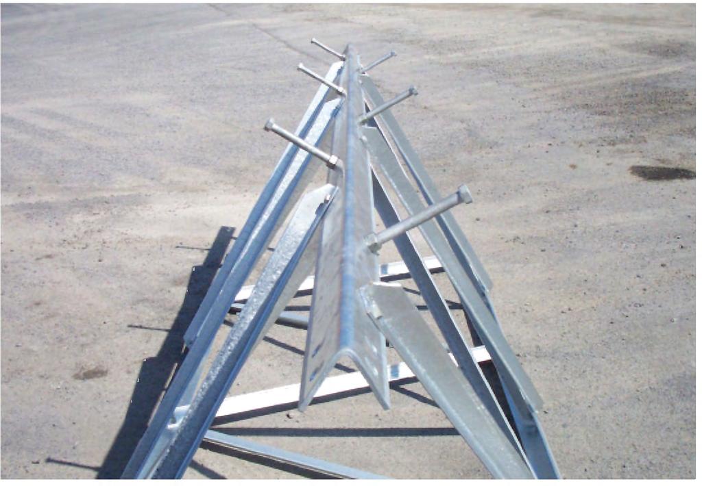
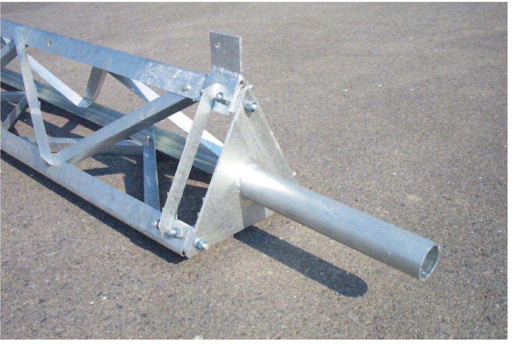
24 Section ssembly

25 Section ssembly

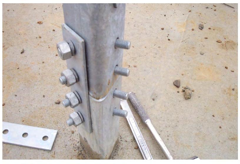
26 Splice Plate Leg onnection
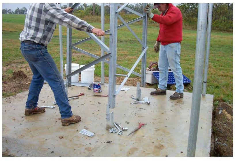
27 Tower Installation
28 Tower Installation
29 Step olts
")
30 Plate Mounts ()
31 Fixed-Mount Mast Plate

32 Thrust earing Plate

33 Rotator / Thrust earing Plates

34 Rotator / Thrust earing Plates

35 nti-limb Panels


36 Rock / Rooftop Mounts

37 Tower Grounding Kit
TOWER INSPECTION REPORT
 3010 S. Hwy 77, Suite 600 Waxahachie, Texas 75165 http://ctctower.com Office: 972/923-9504 Fax: 972/923-9619 TOWER INSPECTION REPORT PREPARED FOR MR. CUSTOMER 1,563 GUYED TOWER NEAR CITY, STATE JANUARY
Page 1 of 1 04/19/13 SBR
 Office of Roadway Engineering - Plan Insert Sheets Number Title Date Number Title Date Number Title Date 201015 Extension of Anchor Bolts 07/20/12 207000 Bikeway Pavement Marking Details 01/18/13 202010
Soma Wind Generators
 Soma Wind Generators 13M WINH TOWER INSTALLATION MANUAL ERTIFIED to AS4100 Steel Structures ode AS3995 (1994) Design of Steel Lattice Towers and Masts AS1170.2 (1989) SAA Wind Loading Manufactured by SOMA
Tripod Setup Guide (M-TPx)
") Items needed: 1/2 inch wrench, mast level (M-MLA), medium size wire cutters, crescent wrench, all-purpose grease, tape measure, tie wraps, redi-mix cement (optional), shovel (optional), sledge hammer (for
Items needed: 1/2 inch wrench, mast level (M-MLA), medium size wire cutters, crescent wrench, all-purpose grease, tape measure, tie wraps, redi-mix cement (optional), shovel (optional), sledge hammer (for
Side-of-Pole Mount for 1 Module (SPM1) For Module Type C
 For Module Type C") Module Type Width Length C 22-27 56-63 Side-of-Pole Mount for 1 Module (SPM1) For Module Type C ASSEMBLY INSTRUCTIONS step-by-step assembly and installation Version 1, Rev A PCN 022212-1 Side-of-Pole Mount
Module Type Width Length C 22-27 56-63 Side-of-Pole Mount for 1 Module (SPM1) For Module Type C ASSEMBLY INSTRUCTIONS step-by-step assembly and installation Version 1, Rev A PCN 022212-1 Side-of-Pole Mount
RSL TOWER KITS RSLL-01-A1 RSL GENERAL NOTES
 SECTION P/N R10H R9H R8H R7 R6 R5 R4 R3 R R1 LENGTH RSLL-1 RSLL- RSLL-3 RSLL-4 RSLL-5 RSLL-6 RSLL-7 RSLL-8 U 3/4" X 1/4" (U 70 X 6.4 mm) RSLL-9 U 3/4" X 1/4" (U 70 X 6.4 mm) RSLL-10 U 3/4" X 1/4" (U 70
Side-of-Pole Mount for 1 Module (SPM1) For Module Types A & B
 For Module Types A & B") Side-of-Pole Mount for 1 Module (SPM1) For Module Types A & B ASSEMBLY INSTRUCTIONS step-by-step assembly and installation Version 1, Rev A PCN 080311-2 SP3363-1 Side-of-Pole Mount for 1 Module (SPM1)
Side-of-Pole Mount for 1 Module (SPM1) For Module Types A & B ASSEMBLY INSTRUCTIONS step-by-step assembly and installation Version 1, Rev A PCN 080311-2 SP3363-1 Side-of-Pole Mount for 1 Module (SPM1)
TorqBolt Wedge Anchors Torque Controlled Expansion Anchor
 TorqBolt Wedge Anchors Torque Controlled Expansion Anchor Product Description The Torqbolt wedge anchor is a torque-controlled, wedge expansion anchor for heavy duty fastening applications where high pull
3/8" Safety Cable Systems
 3/8" Safety Cable Systems Ladder-Mount 3/8" Cable System (No Slider) Kits include appropriate length of aircraft cable, top and bottom support brackets, 12" tensioning turnbuckle, tension spring, and all
TRAVSMART permanent single-cable horizontal lifeline system
 The Travsmart single-line system provides a smooth travel. It allows the traveler to move freely over the intermediate anchors, minimizing wear and eliminating user assistance. The user s hands remain
Installation Instructions MODEL VSTI-A020 Tank Indicator Installation Model: VSTI-A020, Stainless Reverse Read System Versa Steel Inc. Guide Cables No
 Tank Indicator Installation Model: VSTI-A020, Stainless Reverse Read System Guide Cables No Guide Cables 1 August 4, 2011 Assembly Instructions: (Shown with a 2 board, 12 ft kit) ITEM NO. PART NUMBER DESCRIPTION
GP100 SERIES ENDURANCE PLAYGROUND SYSTEMS. Installation and Assembly Instructions. Gared Holdings, LLC 9200 E. 146th St. Noblesville, IN 46060
 GP100 SERIES 1 OF 16 401754712 B Table of Contents Section Page No. Introduction 2 Cautions and Warnings 3 Parts Checklist 4 Post & Extension Arm Installation 7 Acrylic, Glass, and Perforated Steel Backboard
Tower Accessories & Hardware
 Safety-Climb Cable System for Climbing Ladder These Safety-Climb Cable products clamp to climbing ladder rungs up to 1-1/4" (32 mm) in diameter. The products meet or exceed OSH requirements for climbing
BRONZE BUSHING REPLACEMENT PROCEDURE DN345 & NL450C
 1 BRONZE BUSHING REPLACEMENT PROCEDURE V.2 12/3/2014 DN345 & NL450C 2 Safety Instructions Removing Walking Beams 3 1. Position spreader on a flat concrete surface capable of supporting weight of spreader
Sub-Base Assembly For Type-ML 32 & VR-1 Step Voltage Regulator Single-Phase Liquid-Filled Part # GEK 35171
 Transformer Business Department Regulator & Inductive Products Sub-Base Assembly For Type-ML 32 & VR-1 Step Voltage Regulator Single-Phase Liquid-Filled Part # GEK 35171 Last Update 11-19-2013 Tom Dauzat,
Shade Sails - Installation Tips
 Shade Sails - Installation Tips Shade Sails Installation Suggestions Design and Layout: Shade Sails can be mounted in a variety of ways. Sails can be mounted flat or with high and low points. A flat sail
Installation and Training Manual
 AirForce1 Tower Kit Installation and Training Manual FuturEnergy Limited Ettington Park Business Centre Stratford upon Avon CV37 8BT +44 (0)1789 451070 Table of Contents Safety Notes... 3 Parts Supplied
FALLTECH FALL PROTECTION ANCHOR BRACKETS MODEL 7432, Dual Truss/ Ridge Line Roof Anchor Bracket
 FALLTECH FALL PROTECTION ANCHOR BRACKETS MODEL 7432, Dual Truss/ Ridge Line Roof Anchor Bracket WARNING! YOU MUST READ AND FULLY UNDERSTAND OR HAVE THESE INSTRUCTIONS EXPLAINED TO YOU BEFORE USING THIS
WHISPER 42 FOOT (13 Meter) TOWER KIT for SKYSTREAM 3.7 AND WHISPER 500 WIND TURBINE
 TOWER KIT for SKYSTREAM 3.7 AND WHISPER 500 WIND TURBINE") WHISPER 42 FOOT (13 Meter) TOWER KIT for SKYSTREAM 3.7 AND WHISPER 500 WIND TURBINE Made in the USA by: SOUTHWEST WINDPOWER, INC. 1801 Route 66 Flagstaff, AZ 86001 (928) 779-9463 SOUTHWEST WINDPOWER Page
WHISPER 42 FOOT (13 Meter) TOWER KIT for SKYSTREAM 3.7 AND WHISPER 500 WIND TURBINE Made in the USA by: SOUTHWEST WINDPOWER, INC. 1801 Route 66 Flagstaff, AZ 86001 (928) 779-9463 SOUTHWEST WINDPOWER Page
Side-of-Pole Mount for 1 Modules (SPM1) For Module Types E, F, G, & H ASSEMBLY INSTRUCTIONS. step-by-step assembly and installation
 For Module Types E, F, G, & H ASSEMBLY INSTRUCTIONS. step-by-step assembly and installation") Side-of-Pole Mount for 1 Modules (SPM1) For Module Types E, F, G, & H ASSEMBLY INSTRUCTIONS step-by-step assembly and installation Version 1, Rev A SP3348-1 PCN 022212-2 Side-of-Pole Mount for 1 Module
Side-of-Pole Mount for 1 Modules (SPM1) For Module Types E, F, G, & H ASSEMBLY INSTRUCTIONS step-by-step assembly and installation Version 1, Rev A SP3348-1 PCN 022212-2 Side-of-Pole Mount for 1 Module
8MAY15 US RACK, Inc Falcon Drive, Madera, CA
 8MAY15 US RACK, Inc. - 2850 Falcon Drive, Madera, CA 93637-559-661-3050 INSTRUCTIONS for Bedrail-mounted MOTORCYCLE RACK, Model 2001-4TRA WARNING: Do NOT attempt to install or use this rack without following
THOR 10 HAMMER CAGE INSTRUCTIONS
 75 " 7m 78 4" m 6" 8.8m 45 ".70m 4.9deg 6 4" 6m 44 4".67m 75 " 7m 9 4" 0m 44".m 497 4".64m The 70, Thor Hammer Cage, consists of four heavy duty aluminum net poles. The unique pole structure reduces the
QUALITY ALUMINUM BOAT LIFTS, INC. INSTRUCTIONS. Dominator Lake Lift
 INSTRUCTIONS Dominator Lake Lift PHONE:251-986-3882 * FAX:251-986-3136 QABLDOMINATORINST.2014 P a g e 1 Quality Aluminum Boat Lifts, INC. Installation Instructions: Dominator Lake Lift Thank you for your
Thank you for purchasing a Porta-Dock product! *Please read and follow these instructions step by step*
 PG 1 OF 9 PORTA-DOCK, INC. 74A ABL/APW 1056 & 44A FLB APW 1056 PORTA-LIFT Thank you for purchasing a Porta-Dock product! *Please read and follow these instructions step by step* STEP 1. Separate and group
Guyed 70 Foot Tower Kit for Skystream 3.7 Owner s Manual
 Guyed 70 Foot Tower Kit for Skystream 3.7 Owner s Manual 3-CMLT-1028-03 REV F Installation Operation 2013 XZERES Corp All Rights Reserved Please read this manual thoroughly before beginning assembly. If
3 AND 6 SIDE ARMS, STRAIGHT/TAPERED TOWER SECTIONS
 A GENERAL TOWER & SITE ACCESSORIES 3 AND 6 SIDE ARMS, STRAIGHT/TAPERED TOWER SECTIONS 3 6 Tower Leg 2.38 O.D. x 5 Long Mounting Tube Tower Leg 2.38 O.D. x 5 Long Mounting Tube 3 Side Arm 6 Side Arm UNIVERSAL
Troyer s Gourd Rack 8 unit F R H O P
 B E A D I M-N L Vertical Parts F R H O P Horizontal Parts C G J Updated 11/16 Parts List A: Top of Pole B: Bottom of Pole C: 48 Ground Stake D: Top Perch rods 48 long E: Hub F: Rope Winder w/ attached
Reproduction. Not for. Installation Instructions. Installation Instructions. Part No Installation. 32/36 Bagger 32/36 Kit WARNING
 Installation Instructions Installation Instructions 32/36 agger 32/36 Kit Part No. 5600268 its 32/36 Mowers Kit ontents Part No. Qty. escription Part No. Qty. escription 5404389 1 Weld, agger Mount, 32/36
Low Wind High Yields Series
 Low Wind High Yields Series Wind Turbines USER S MANUAL Introduction Low Wind High Yields Series rotor blades apply the latest advanced thermoplastic engineering and are manufactured by precision injection
Utility Anchor System
 Utility Anchor System The Dayton Superior Utility Anchor System is designed to economically simplify the lifting and handling of precast concrete elements. Its economics, ease of use and versatility will
Wellhead Mast. Installation and Operation Guide. Nanometrics Inc. Kanata, Ontario Canada
 Installation and Operation Guide Nanometrics Inc. Kanata, Ontario Canada 2001 2005 Nanometrics Inc. All Rights Reserved. Installation and Operation Guide The information in this document has been carefully
FIRST TEAM SPORTS, INC Storm Portable Series Assembly Instructions
 FIRST TEAM SPORTS, INC Storm Portable Series Assembly Instructions WARNING! WARNING! WARNING! THIS BASKETBALL SYSTEM IS SPRING LOADED AND SHIPPED UNDER TENSION. ATTEMPTING TO ASSEMBLE OR DISASSEMBLE ANY
Safety System Installation Guide for ARE Wind Poles
 Safety System Installation Guide for ARE Wind Poles V. 1 May 2011 ** Climbing pegs and ladder should be installed before the pole is erected.** A. Install climbing pegs Install climbing pegs (bolt set)
VL 2K LIFT D-L WINCH INSTRUCTIONS (Applies to P/Ns , , , , , )
") VL 2K LIFT D-L WINCH INSTRUCTIONS (Applies to P/Ns 3714022, 3714028, 3714034, 3714040, 3714043, 3714046) REIMANN & GEORGER CORPORATION MARINE PRODUCTS BUFFALO, NY P/N 6112103 04/09/18 1 SAFETY 1.1 INTRODUCTION
VL 2K LIFT D-L WINCH INSTRUCTIONS (Applies to P/Ns 3714022, 3714028, 3714034, 3714040, 3714043, 3714046) REIMANN & GEORGER CORPORATION MARINE PRODUCTS BUFFALO, NY P/N 6112103 04/09/18 1 SAFETY 1.1 INTRODUCTION
Installation and Service Manual
 An Actuant Company Installation and Service Manual Heavy Duty Hydraulic Stabilization Legs CONTENTS Part # 3010003129 REV 0D Section Page 1.0 Receiving Instructions 2 2.0 Safety Issues 2 3.0 Hydraulic
CAUTION - PUT SAFETY FIRST
 www.shoremaster.com DVS Vertical Lift (Double V Side): Frame ssembly Instructions. Models: 500DVS - 0ft Wide, 5000lb Capacity - Part #: 0079 600DVS - 0ft Wide, 6000lb Capacity - Part #: 0033.. 3.. 5. CUTION
REVIEW ALL INSTALLATION NOTES PRIOR TO INSTALLATION!
 Page 1 of 7 HD NON-PENETRATING ROOF MOUNT ASSEMBLY INSTRUCTIONS REVIEW ALL INSTALLATION NOTES PRIOR TO INSTALLATION! INSTALLATION NOTES General 1) These general structural notes are intended to augment
20', 15', AND 12' BALL STOPS ASSEMBLY INSTRUCTIONS
 20'-0" 15'-0" 1 739020 739020A 20' BALL STOP; STRAIGHT POLE 739015 739015A 15' BALL STOP; STRAIGHT POLE 739012 739012A 12' BALL STOP; STRAIGHT POLE Read all of the instructions before beginning. Make sure
LEGACY II TM STARTING PLATFORMS
 LEGACY II TM STARTING PLATFORMS INSTALLATION INSTRUCTIONS CORPORATE HEADQUARTERS WESTERN SALES AND MANUFACTURING PLANT P.O. Box 400 1017 SW Berg Parkway Canby, Oregon 97013 (503) 266-2231 Fax (503) 266-4334
S Surge Arresters
 Surge Arresters UltraSIL Polymer-Housed VariSTAR Type US, UH, and UX Station-Class Surge Arresters Installation and Maintenance Instructions Service Information S235-88-1 Contents Product Information...........................1
ROCKSOLID SINGLE POST ANCHOR
 ROCKSOLID SINGLE POST ANCHOR INSTALLATION INSTRUCTIONS YOU MUST USE THE ANCHOR SET TOOL (PART #27-109) TO INSURE PROPER INSTALLATION SRS AUSTRALIA, PTY LTD 12 Enterprise St Richlands QLD 4077 Australia
Instant Garage 16' x 12' 3" x 8' 6"
 Instant Garage 16' x 12' 3" x 8' 6" Assembly Instructions Door Height 1.8M A B DESRIPTION MODEL # A B IG 1216 Instant Garage 4.9 x 3.7 x 2.6 M - Grey 3503500 16' x 12' 3" x 8' 6" REOMMENDED TOOLS OR Please
STATIONARY TRUCK INTERNAL HALYARD V-CLEAT FLAGPOLES FOR QUICK AND PROFESSIONAL INSTALLATION READ ALL INSTRUCTIONS BEFORE PROCEEDING
 9390 South 300 West, Sandy, Utah 84070 801-562-0123 800-782-0500 ColonialFlag.com STATIONARY TRUCK INTERNAL HALYARD V-CLEAT FLAGPOLES FOR QUICK AND PROFESSIONAL INSTALLATION READ ALL INSTRUCTIONS BEFORE
Backboard and Rim Owners Manual
 REQUIRED TOOLS AND MATERIALS: Two (2) Capable Adults Tape Measure Backboard and Rim Owners Manual Customer Service Center N53 W24700 South Corporate Circle Sussex, WI 53089 U.S.A. Step Ladder - 8ft. (2.4
Assembly Guide ST200 FUNCTIONAL TRAINER
 Assembly Guide ST200 FUNCTIONAL TRAINER Assembly Guide ST200 FUNCTIONAL TRAINER To avoid possible damage to this Functional Trainer, please follow these assembly steps in the correct order. Before proceeding,
Advantage Lockers & Bike
 Advantage Lockers & Bike Advantage Bike Racks & Lockers Inc. is the #1 supplier of Storage Lockers and Bike Racks to the Lower Mainland s residential construction industry. With 25+ years of experience
Vertical Lift: Frame Assembly Instructions. Model: ft Wide 7000lb Capacity - Part #:
 www.shoremaster.com 70068 Vertical Lift: Frame ssembly Instructions. Model: 70068-0ft Wide 7000lb apacity - Part #: 0070. 2. 3.. 5. UTION - PUT SFETY FIRST Before attempting to install or operate this
Reliance Industries, LLC Operating instructions for the / Bolt-on D-Ring Anchorage. Model # 3071
 Reliance Industries, LLC Operating instructions for the 3071-1 / 3071-2 Bolt-on D-Ring Anchorage Model # 3071 Reliance Industries, LLC PO Box 140008 Denver, CO 80214 Ph. (800) 488-5751 Ph. (303) 424-8650
POP UP ANCHOR. Part Number Spectrum Lane ~ Missoula MT ~
 POP UP ANCHOR Part Number 153169 7100 Spectrum Lane ~ Missoula MT 59808 800.791.8056 ~ www.spectrumproducts.com You have purchased a Spectrum Products Pop Up Lane Rope Anchor. Providing the unit is installed
WHEATLEY Series 500 Swing Check Valve
 Document Number: TC003001-13 Revision: 02 WHEATLEY Series 500 Swing Check Valve Installation, Operation, and Maintenance Manual TABLE OF CONTENTS BILL OF MATERIALS...3 SCOPE...5 INSTALLATION AND OPERATION
Parts List. Description. Additional Considerations. Installation Instructions. Dual/Elite Hydraulic Treadmill Kit (supplied by EPI)
") Page 1 of 9 Parts List Dual/Elite Hydraulic Treadmill Kit (supplied by EPI) Qty Description Treadmill Body 1 Treadmill Power Unit (per Treadmill Body) 2 Treadmill Decks (per Treadmill Body) 1 Treadmill
Page 1 of 9 Parts List Dual/Elite Hydraulic Treadmill Kit (supplied by EPI) Qty Description Treadmill Body 1 Treadmill Power Unit (per Treadmill Body) 2 Treadmill Decks (per Treadmill Body) 1 Treadmill
Specifications Testing & Adjusting Disassembly & Assembly
 SB4191E00 Jul. 2005 Specifications Testing & Adjusting Supplement for Quad Lift Mast D20/25/30/32/33S-3 G/GC20/25/30/32P-3 G/GC20/25/30/32E-3 Important Safety Information Most accidents involving product
BALL STOP INSTALLTION GUIDE
 BALL STOP INSTALLTION GUIDE GROUND SLEEVE INSTALLATION: 1. Locate the exact location of the ground sleeve. NOTE: Maximum recommended pole spacing is 20 feet on center. 2. Excavate the pole footing; refer
Marine 6-Boat Free-Standing Racks SKU: Updated November 2011
 Marine 6-Boat Free-Standing Racks SKU: 30-061 Updated November 011 Contains: Marine -Boat Free-Standing Racks (SKU 1-003) Marine 3 rd Boat Expansion Racks (SKU 1-0303) Marine Back Legs (SKU -001) 3 Sets
Import Bike Rack OEM INSTALLATION MANUAL
 Import ike Rack OEM INSTLLTION MNUL TLE OF ONTENTS System Information 2 Safety Information 2 Resources Required 3 Preparation 3 Under umper ttachment 3 Over umper ttachment 3 Installation 3 Under umper
User Manual 1792 Standing Seam Metal Roof Retractable Swivel Anchor
 1 User Manual 1792 Standing Seam Metal Roof Retractable Swivel Anchor This manual is intended to meet the Manufacturer Instructions as required by ANSI Z359.1 and should be used as part of an employee
CAISSON SHAFT SYSTEM
 CAISSON SHAFT SYSTEM Installation Guide INSTALLATION GUIDE FOR DN2000 TO DN3660 UNITS PLATE JOINTING SYSTEM This guide is to be used for the Installation of CPM Group Ltd caisson shaft units which use
Torque Specifications
 SENR3130-10 Torque Specifications All Caterpillar Products S/N From the library of Barrington Diesel Club CONTENT General Information 01/07/2005 Introduction to Torque 01/07/2005 Torque-Turn 01/07/2005
Explain that this is how I did my tower, it does not necessarily represent the state of the art, nor even the right way to do any particular aspect
 Explain that this is how I did my tower, it does not necessarily represent the state of the art, nor even the right way to do any particular aspect of the tower. I invite those more experience to make
IBS, INCORPORATED Index Washers W A S H E R S. Washers, Lock Alloy C-8 External Tooth C-10. Internal Tooth C-10
 IB, INCOPOTD Index ashers ssortments Flat asher Copper C-11 Fender asher C-9 eavy Duty C-5 Lock asher Internal & xternal tar asher C-10 ur-lock Vibration-esistant ashers C-7 Back-Up ashers luminum ound
STATIONARY TRUCK INTERNAL HALYARD CAM CLEAT FLAGPOLES FOR QUICK AND PROFESSIONAL COMMERCIAL INSTALLATION READ ALL INSTRUCTIONS BEFORE PROCEEDING
 9390 South 300 West, Sandy, Utah 84070 801-562-0123 800-782-0500 ColonialFlag.com STATIONARY TRUCK INTERNAL HALYARD CAM CLEAT FLAGPOLES FOR QUICK AND PROFESSIONAL COMMERCIAL INSTALLATION READ ALL INSTRUCTIONS
SAMPLE PAGE. Section 2... Wire Rope
 Section 2...................................................... Wire Rope Never use any kind of clip to directly connect two straight lengths of wire rope to form a continuous piece. Do not make up slings
For Review Only No Copying No Saving No Lending No Posting Online
 The following copyrighted samples are provided as a service for your review only. Copying, saving, lending, posting online or any general use of these files other than for the purpose provided is unlawful
PORTABLE LIGHTNING MAST PROTECTION PLP SERIES INSTRUCTION MANUAL
 PORTABLE LIGHTNING MAST PROTECTION PLP SERIES INSTRUCTION MANUAL LBA Technology, Inc. Greenville, NC May 20, 2014 Rev 061515 NOTICE This Instruction Manual is prepared by LBA Technology, Inc. specifically
VK/VP SERIES : Sealless Vertical Pump. Assembling Instructions 2010
 VK/VP SERIES : Sealless Vertical Pump Assembling Instructions 2010 20610 Manhattan Place Suite 116 Torrance, CA 90501 Phone: 310-328-9114 Fax: 310-328-9441 1. Motor Shaft and Pump Base (1) (2) Place a
CLEANROOM GEL GRID CEILING SYSTEM PRODUCT DATA Division
 5023 HAZEL JONES ROAD, BOSSIER CITY, LA 71111 888.315.1561 800.877.8746 FAX SALES@GORDONCLEANROOM.COM GORDONCLEANROOM.COM AN EMPLOYEE OWNED COMPANY CLEANROOM GEL GRID CEILING SYSTEM PRODUCT DATA Division
MICHIGAN DEPARTMENT OF TRANSPORTATION 6" X 8" (NOMINAL POST) 3-1/2" DIA. 2 HOLES TAPERED HARD WOOD WEDGES (HARDWOOD WEDGE
 3-1/2 DIA. 2 HOLES TAPERED HARD WOOD WEDGES (HARDWOOD WEDGE") X (NOMINAL POST) 1-1/ DIA. 2 HOLES X 8" (NOMINAL POST) 3-1/ DIA. 2 HOLES TAPERED HARD WOOD WEDGES (HARDWOOD WEDGE TO BE OAK, MAPLE OR OTHER APPROVED DENSE HARDWOODS) TO HOLD POST IN A STABLE POSITION AFTER
X (NOMINAL POST) 1-1/ DIA. 2 HOLES X 8" (NOMINAL POST) 3-1/ DIA. 2 HOLES TAPERED HARD WOOD WEDGES (HARDWOOD WEDGE TO BE OAK, MAPLE OR OTHER APPROVED DENSE HARDWOODS) TO HOLD POST IN A STABLE POSITION AFTER
OWNER'S MANUAL. Turnbuckle. Stanchions. Warning
 GEMTOR, INC....when your life is on the line One Johnson Avenue Matawan, NJ 07747 732-583-6200 800-405-9048 Fax 732-290-9391 OWNER'S MANUAL Installation, Operating, Inspection and Maintenance Instructions
M2 Antenna Systems, Inc. Model No: VLP16
 M2 Antenna Systems, Inc. Model No: 100-600VLP16 SPECIFICATIONS: Model... 100-600VLP16 Frequency Range... 100-600 MHz Cont. *Gain... 9.64 dbi Front to back... 12 db Typical Beamwidth... E=64 / H=70 Feed
MSA Confined Space Entry Equipment
 MSA Confined Space Entry Equipment Because every life has a purpose... MSA Confined Space Entry Equipment MSA XTIRPA Manhole Guard System Use for confined space vertical entry and fall protection when
Assembly Instructions. -Cantilever Boat Lifts
 Assembly Instructions -Cantilever Boat Lifts Winch Instruction Page Safety Information 1. The winch is built for the multipurpose of hauling and lifting operations. It is not to be used as a hoist for
Stand-N-Fish FULL DETAIL INSTALLATION INSTRUCTIONS
 1 Stand-N-Fish FULL DETAIL INSTALLATION INSTRUCTIONS Thank you for purchasing the incredible new Stand-N-Fish Kayak Fishing System. Once installed on your kayak the Stand-N-Fish will take your kayak fishing
Installation, Operation & Maintenance Manual
 Original Instructions Installation, Operation & Maintenance Manual Sentry VREL Control Valve Pressure Conditioning S-SW-IOM-00277-15 1-17 Table of Contents Safety Information... 3 General Safety Precautions...
User Instructions 1789 Parapet Wall Anchor
 User Instructions 1789 Parapet Wall Anchor This manual is intended to meet the Manufacturer Instructions as required by ANSI Z359.1 and should be used as part of an employee training program as required
Only. Gives You the TechLock. System Advantage ASSEMBLY, DISASSEMBLY AND TROUBLESHOOTING INSTRUCTIONS FOR 3000 SERIES FONTAINE
 April 00 Only Gives You the TechLock System Advantage ASSEMBLY, DISASSEMBLY AND TROUBLESHOOTING INSTRUCTIONS FOR 000 SERIES FONTAINE C o n n e c t y o u r b u s i n e s s w i t h F O N T A I N E April
Airwalker. Installation and Safety Information. Stretch Products for Dance, Therapy, Education, and Fitness
 Airwalker Installation and Safety Information Stretch Products for Dance, Therapy, Education, and Fitness www.dyenamicmovement.com Airwalker is a Registered Trademark of Dye namic Movement Products, Inc.
ROOF ANCHOR / D-RING ANCHOR PLATE
 RIGGERS SAFETY Riggers Safety LLC. 267 Winfield Cr. Corona, CA 92880. 951 371 8586. www.riggerssafety.com Use and Safety Manual ROOF ANCHOR / D-RING ANCHOR PLATE Table of Contents WARNINGS 3 Definitions
WHEATLEY WHEATLEY SERIES 500 SWING CHECK VALVE. Installation, Operation and Maintenance Manual
 WHEATLEY SERIES 500 SWING CHECK VALVE STANDARD INTEGRAL SEAT & OPTIONAL REMOVABLE SEAT 2" FP - 6" FP 150# - 1500# 8" FP - 12" FP 150# - 900# API 6D and B16.34 2" FP - 4" FP 5000# DRILLING PRODUCTION VALVE
Parts & Installation Instructions SV & SV 2 8.5, 9.5 & 10.5 and SVLD 7.5 Snow Plow
 Form -0 R September 0 Parts & Installation Instructions SV & SV.,. &. and SVLD. Snow Plow Item Part No. Part No. Part No. Part No. Part No. Part No. Qty. Description SVLD. SV. SV. SV. SV. SV. Moldboard
USER / ARMORER MANUAL
 USER / ARMORER MANUAL FOR ALL DANIEL DEFENSE DD WAVE SUPPRESSORS & MUZZLE ADAPTERS 1 TABLE OF CONTENTS 1. DANIEL DEFENSE SUPPRESSOR SYSTEMS...3 2. ACME THREAD QUICK-CLAMPING SYSTEM QUICK REFERENCE...4
GUARDIAN FALL PROTECTION
 2015 V2 GUARDIAN FALL PROTECTION Product Mini Catalog 2015 For more information, go to www.guardianfall.com or call 800.466.6385 OUR VISION TO ALWAYS BE THE MARKET S FIRST CHOICE FOR FALL PROTECTION AND
Instruction Manual for ZY-021 Height adjustable Acrylic Backboard with Chain net
 Instruction Manual for ZY-021 Height adjustable Acrylic Backboard with Chain net WARNING: IMPROPER INSTALLATION OR SWINGING ON THE RING MAY CAUSE SERIOUS INJURY OR DEATH Notice to assemblers: All basketball
GENERAL GUIDELINES FOR PROPER RIGGING PRACTICES AND INSPECTION & REMOVAL CRITERIA FOR SLINGS PER OSHA
 GENERAL GUIDELINES FOR PROPER RIGGING PRACTICES AND INSPECTION & REMOVAL CRITERIA FOR SLINGS PER OSHA 1910.184 SAFE OPERATING PRACTICES -.Whenever any sling is used, the following practices shall be observed:
Instant Garage 20' x 12' 3" x 8' 3"
 Instant Garage 20' x 12' 3" x 8' 3" Assembly Instructions Description Model # Instant Garage 20' x 12' 3" x 8' 3" - Grey CIG 1220 3503502 Recommended Tools OR THIS IS A TEMPORARY STRUCTURE AND NOT RECOMMENDED
Tread Brake Assembly Instructions
 reated: 9/06/202, Revision: 2/20/204 Tread rake ssembly Instructions Table of ontents: Lower rake omponents..2-4 able rake ssembly: rake Handle omponents..5-7 able ssembly....8 Tee Handle rake ssembly...9-0
310 SERIES TILT-TO-LOAD ROTATOR. The Specialist In Drum Handling Equipment
 OPERATOR S MANUAL FOR MORSE TILT-TO-LOAD DRUM ROTATOR SAFETY INFORMATION: While Morse Manufacturing Co. drum handling equipment is engineered for safety and efficiency, a high degree of responsibility
S110 Steel Level Panel Installation Instructions
 S110 Steel Level Panel Installation Instructions NOTE: Fairway Architectural Railing Solutions will not be held liable for incorrect or unsafe installations by installer. It is the installer s resposibility
sarens
 sarens group www.sarens.com Sarens Climbing Tower SCT The SARENS CLIMBING TOWER is designed for lifting heavy loads in the construction, petrochemical and offshore industries. The system is suited to using
ORNAMENTAL CANTILEVER GATE INSTRUCTIONS
 U.S.A. Patent Number 5,36,83 ORNAMENTAL CANTILEVER GATE INSTRUCTIONS *NOTICE: Ornamental Cantilever Gates are supplied with rolls of 2 mesh safety screening in sufficient quantities to cover the entire
Soccer Goal. Model: SG20 Series. Installation, Operation and Maintenance Instructions
 Soccer Goal Model: SG20 Series Installation, Operation and Maintenance Instructions Please read all instructions before attempting installation or operation of these units SAVE THESE INSTRUCTIONS FOR FUTURE
#59114 Rola 2-Bike Rack Carrier (Shown Assembled) (A) (C) (B)
 (A) (C) (B)") Use for Parts: #59114 Rola -Bike Rack System #59115 Rola 1-Bike Add-On TOOLS REQUIRED 10mm or 13/3 Socket & Wrench #59114 Rola -Bike Rack Carrier (Shown Assembled) Tray Attachment Hardware: (3) Plastic
Use for Parts: #59114 Rola -Bike Rack System #59115 Rola 1-Bike Add-On TOOLS REQUIRED 10mm or 13/3 Socket & Wrench #59114 Rola -Bike Rack Carrier (Shown Assembled) Tray Attachment Hardware: (3) Plastic
5. STRUCTURAL ANALYSIS
 5. STRUCTURAL ANALYSIS The skeletal structure of the experiment casing is constructed from UNISTRUT with all experiment equipment mounted by UNISTRUT provided fasteners. All maximum loads for nuts, bolts,
BC Shackle. Made in the China. Alloy Steel Anchor Shackle. Instructions for handling and use - Please read in full before using this device
 BC Shackle Made in the China Alloy Steel Anchor Shackle Instructions for handling and use - Please read in full before using this device Index 1.) Introduction 2.) Warnings / General Use Guidelines 3.)
SERIES 2 RAMP OWNER S MANUAL TOOLS REQUIRED: BEFORE YOU BEGIN... Read and understand these instructions before beginning a ramp setup.
 SERIES 2 RAMP OWNER S MANUAL BEFORE YOU BEGIN... Read and understand these instructions before beginning a ramp setup. Use caution and care for your back when lifting, pushing, pulling, folding or unfolding
CENTER-STRUT HEIGHT ADJUSTMENT UNITS MANUAL OPERATION
 ASSEMBLY, INSTALLATION &MAINTENANCE INSTRUCTIONS CENTER-STRUT HEIGHT ADJUSTMENT UNITS MANUAL OPERATION No. 00900-211 and 00900-506 Nylon spacer (2) located between fan backboard support and backboard FAN
OUTDOOR BACKSTOP WITH 5'-0" EXTENSION
 INSTALLATION INSTRUCTIONS OUTDOOR BACKSTOP WITH 5'-0" EXTENSION NoUU. 00175- _ READ ALL INSTRUCTIONS THOROUGHLY BEFORE ATTEMPTING TO INSTALL THIS EQUIPMENT. INSTALLATION / ASSEMBLY OF THIS EQUIPMENT MUST
BARRIER OFFSET 0" A 6" 6" A 12" 12" A 26" A 26" 3A OR 4A L OR S * ** L OR S L OR S
 ACCEPTABLE (TCB) TYPES AND ANCHORING DETAILS BASED ON UNDERLYING SURFACE TYPE AND BARRIER OFFSET FROM DROP-OFF BARRIER OFFSET UNDERLYING SURFACE 0" A 6" 6" A 12" 12" A 26" A 26" TCB TYPE DETAIL TCB TYPE
Nautique Triton Clamping Board Rack V2
 w w w.ro swe l l marine.co m Nautique Triton Clamping Board Rack V2 Installation & Usage Instructions Part # C917-180045 Information: info@roswellmarine.com If you have any questions please call : 1-21-68-11
Installation Instructions
 116-3027, 116-3017 X-Pando Adjustable Steel Protector Installation Instructions 1404 N. Marshall Ave. El Cajon CA. 92020 For technical support call us at (800) 368-3075 NB 6/28/10 607-0112 Step 1. Mounting
Standard Hangers and Adapters
 Standard s and Adapters Cable Gripping Tabs Prevent cable slippage without the need for a permanently installed hoisting grip. Pre-Assembled and Captivated Hardware Eliminates the need for field assembly.