Control and Automation
|
|
|
- Noah Baldwin
- 5 years ago
- Views:
Transcription

1 GE Consumer & Industrial Power Protection Control and Automation Electronic relays GE imagination at work
2 Electronic relays Order codes F.3 Series DM Single voltage electronic timers. 22.5mm module F.4 Series NMV Multivoltage electronic timers. 22.5mm module F.6 Series D Single voltage electronic timers. 45mm module F.7 F.8 Liquid level detectors relay Earth leakage relays Plug-in relays and Auxiliary contactors A F.9 F.10 Protection relays Detection relays Motor protection devices B F.11 F.11 Control and protection relays Auxiliary function Contactors and Thermal overload relays C F.12 Standard suplpy voltages Technical data Motorstarters D F.14 F.16 Series DM Series NMV Control and signalling units E F.24 Series D Electronic relays F F.40 Dimensions Series DM, NMV, D Limit switches G Speed drive units H Main switches I under control Numerical index X F.1

3 Series DM, NMV, D Series DM Single voltage 22.5mm module Series NMV Multivoltage 22.5mm module Series D Single voltage 45mm module Electronic relays A Range overview Series DM Single voltage Standards VDE 0106 VDE 0110 EN EN mm module CSA C 22.2 Nr.14 UL 94 UL 508 IEC Series NMV Multivoltage UNE IEC/EN IEC/EN mm module Series D Single voltage B C D E F G H I X Delay Delayed ON ON delay with auxiliary contact ON delay + instantaneous contact OFF delay OFF delay with auxiliary contact ON + OFF with auxiliary contact Star-delta starter Multifunction Impulse Delayed ON ON delay with auxiliary contact OFF delay with auxiliary contact ON + OFF with auxiliary contact Intermittence Symmetric intermittence Asymmetric intermittence Control Motor re-start control relay Detectors Liquid level detector relay Voltage detector relay Current detector relay Current detector relay with delay Relay Differential earth leakage Thermistor relay Adjustable thermistor relay Frequency control relay Protection (three-phase lines) Integral protection relay for 3-ph. lines Unbalance and phase failure Phase failure, unbalance and 3-ph min. voltage Phase sequence Phase sequence and phase failure Maximum and minimum voltage Protection (single-phase lines) Maximum and minimum voltage Pg. MRD F.3 MET F.3 Pg. MTC F.3 Pg. Pg. Pg. Pg. NMTCV F.4 NMTCSV F.4 NMMFV F.5 MMFV F.5 NMTCIV F.4 NMRDV F.5 NMTDV F.5 NMMFV F.5 NMMFV F.5 NMETV F.4 NMMFV F.5 NMICV F.4 NMMFV F.5 NMMFV F.5 NMMFV F.5 NMMFV F.5 NMIFV F.5 NMIVV F.5 NMIVVL F.5 Pg. RET50 F.6 RCR1 F.7 DINIL F.7 RDT F.10 RDI F.10 RDIT F.10 RDHT/A F.8 RS01N F.11 RSR F.11 RCF F.11 RDFF1 F.9 RPDF F.9 RDMT1 F.9 RSF F.9 RSFF F.9 RTMM F.9 RMM F.9 F.2
4 Series DM Single voltage electronic timers. 22.5mm module Supply Voltage Time Available Cat. no (1) Ref. no. Pack voltage (V) range contacts Delayed ON relay Direct sec 1 changeover MTCAN sec sec sec. Technical data: see F.14 Star-delta starter relay Direct 2-50 sec. 2 changeover METAN With transformer (2) 2-50 sec. 2 changeover MET t AN Technical data: see F.15 Delayed OFF relay Direct sec. 1 changeover MRD-5AN sec. MRD-10AN sec. MRD-50AN sec. MRD-100AN sec. MRD-700AN Technical data: see F.15 Electronic relays of 22.5 mm A B C D E F G H I X Standard supply voltages! pg. F.12 Technical data! pg. F.14 Dimensions! pg. F.40 F.3
5 Series NMV Multivoltage electronic timers. 22.5mm module Delayed ON relay Supply Time Available Cat. no (1) Ref. no. Pack voltage range contacts Direct 0.06 sec h. 1 changeover NMTCV V AC/DC 0.06 sec h. 2 changeover NMTCV With transformer (2) 0.06 sec h. 1 changeover NMTCV t see bottom 1 Technical data: see F.16 Electronic relays A Delayed ON with instantaneous contact Delayed ON with thyristor output timer (3) Direct 0.06 sec h. 1 timed contact NMTCIV V AC/DC 0.06 sec h. + 1 instant contact Technical data: see F.17 Direct sec. Thyristor output NMTCSV sec sec sec. Technical data: see F.18 B C Impulse ON timer Direct 0.06 sec h. 1 changeover NMICV V AC/DC Technical data: see F.18 D E F G H Star-delta starter Direct 1-10 sec. 1 changeover NMETV V AC/DC 6-60 sec. With transformer (2) 1-10 sec. 1 changeover NMETV t see bottom sec. Technical data: see F.19 (1) To complete the catalogue number, replace the symbol by the code corresponding to the voltage and the frequency of the control circuit, according to the tables on F.12 and F.13 (2) Transformator inside the timerhousing (3) Not UL approved I X Standard supply voltages! pg. F.12 Technical data! pg. F.16 Dimensions! pg. F.40 For reference numbers, see chapter X, pg. X.14 F.4
6 Series NMV Multivoltage electronic timers. 22.5mm module (continued) Supply Time Available Cat. no (1) Ref. no. Pack voltage range contacts Delayed OFF timer Direct sec. 1 changeover NMRDV V AC/DC 5-60 sec. 1 changeover NMRDV sec. 1 changeover NMRDV sec. 2 changeover NMRDV sec. 2 changeover NMRDV sec. 2 changeover NMRDV With transformer (2) sec. 1 changeover NMRDV t-6 see bottom sec. 1 changeover NMRDV t-60 see bottom sec. 1 changeover NMRDV t-600 see bottom 1 Technical data: see F.19 Delayed OFF through contact timer Symmetric intermittence Direct 0.06 sec h 1 changeover NMTDV V AC/DC Technical data: see F.20 Direct 0.06 sec h 1 changeover NMIFV V AC/DC Technical data: see F.20 Electronic relays of 22.5 mm A B Asymmetric intermittence, started by connection or pause (choice) Direct 0.06 sec h 1 changeover NMIVV V AC/DC Technical data: see F.21 C D Multifunction - Delayed ON timer - Delayed ON through contact timer - Delayed OFF through contact timer - Delayed ON and OFF through contact timer - Impulse ON timer - Impulse ON through contact timer - Impulse OFF through contact timer - Impulse ON and OFF through contact timer Module 22,5mm Direct 0.6 sec h 1 changeover NMMFV V AC/DC Module 45mm Direct 0.6 sec h V AC/DC With transformer 0.6 sec h 2 changeover NMMFV t 2 see bottom 1 E F G H I (1) To complete the catalogue number, replace the symbol by the code corresponding to the voltage and the frequency of the control circuit, according to the tables on F.12 and F.13 (2) Transformator inside the timerhousing X For reference numbers, see chapter X, pg. X.14 F.5
7 Series D Single voltage electronic timers. 45mm module Star-delta starter relay Supply Voltage Available Time Cat. no (1) Ref. no. Pack voltage (V) contacts range Direct and with RET sec. RET 50ENU transformer (3) changeover Technical data: see F.23 Electronic relays Motor re-start control relay Direct and with RCR sec. RCR 1 see bottom 1 transformer (2) 1 changeover (memory time) RCR 1EN RCR 1AJ Technical data: see F.24 Motor re-start control relay (plug in) Direct and with RCRT sec. RCRT 6-60 see bottom 1 transformer (2) 1 changeover (memory time) sec. (delayed time) Technical data: see F.24 A B (1) To complete the catalogue number, replace the symbol by the code corresponding to the voltage and the frequency of the control circuit, according to the tables on F.12 and F.13 (2) Possibility of fitting a remote potentiometer. (3) Transformator inside the timerhousing C D E F G H I X Standard supply voltages! pg. F.12 Technical data! pg. F.23 Dimensions! pg. F.40 For reference numbers, see chapter X, pg. X.14 F.6
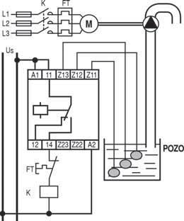
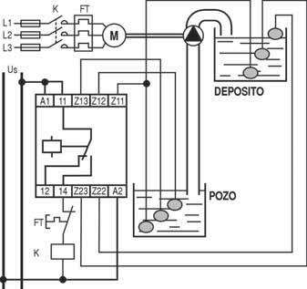
8 Series D Liquid level detector relay Supply Contacts No. of Cat. no. (1) Ref. no. Pack voltage circuits With transformer (2) DINIL... 2 DINIL 02 see bottom 1 1 changeover 1 DINIL 03 see bottom 1 DINIL...E 2 DINIL 02E ENU (plug in) 1 DINIL 03E ENU changeover 11 pins socket for DINIL-02E, -03E. PRCZ for panel fixing. Front terminals Technical data: see F.24 F.25 (DINIL 02) F.26 (DINIL 02E) F.27 (DINIL 03) F.28 (DINIL 03E) Probes Cable union and probe encapsulated and 5 meters SON protected by thermoplastic housing. 10 meters SON Stainless steel probe. Without cable. Waterproof and protected with a SON thermoplastic housing. Stainless steel probe. (1) To complete the catalogue number, replace the symbol by the code corresponding to the voltage and the frequency of the control circuit, according to the tables on F.12 and F.13 (2) Transformator inside the timerhousing Electronic relays of 45 mm A B C D E F G H I X For reference numbers, see chapter X, pg. X.14 F.7
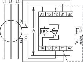
9 Series D Electronic relays A B Differential earth leakage relay with hand reset (with test) Differential earth leakage relay with automatic reset (with test) Earth leakage relays. 45 mm module Supply Contacts Sensiv. Ø voltage (A) (mm) Differential transformers Earth leakage relays Cat. no (1) Ref. no. Pack Cat. no (1) Ref. no. Pack see bottom RDHT WKAT 35-1,2A/2V RDHT 1-1,2 1 With test 70 WKAT 70-1,2A/2V changeover 105 WKAT 105-1,2A/2V WKAT 140-1,2A/2V WKAT 210-1,2A/2V WKAT 35-10A/2V RDHT WKAT 70-10A/2V WKAT A/2V WKAT A/2V WKAT A/2V Technical data: see F.29 Direct and with RDHA WKAT 35-1,2A/2V RDHA 1-1,2 1 transformer (2) With test 70 WKAT 70-1,2A/2V changeover 105 WKAT 105-1,2A/2V WKAT 140-1,2A/2V WKAT 210-1,2A/2V WKAT 35-10A/2V RDHA WKAT 70-10A/2V WKAT A/2V WKAT A/2V WKAT A/2V Technical data: see F.29 (1) To complete the catalogue number, replace the symbol by the code corresponding to the voltage and the frequency of the control circuit, according to the tables on F.12 and F.13 (2) Transformator inside the timerhousing C D E F G H I X Standard supply voltages! pg. F.12 Technical data! pg. F.29 Dimensions! pg. F.40 For reference numbers, see chapter X, pg. X.14 F.8
10 Series D Protection relays Integral protection relay for three-phase lines Supply Contacts Operating range Unbalance Mains Cat. no (1) Ref. no. Pack voltage contact Umin. Umax. frequency see bottom With RDFF % 5-15% % 50 Hz RDFF transformer (2) 1 changeover 60 Hz RDFF Technical data: see F.30 Unbalance and phase failure protection relay for three-phase lines Unbalance, phase failure and minimum voltage protection relay for three-phase lines Direct and with RPDF transformer (2) 2 changeover Technical data: see F.31 With RDMT transformer (2) 1 changeover Technical data: see F % 50 Hz RPDF Hz RPDF Voltage 0-20% 2-10% 220V 50 Hz RDMT1-50AN V RDMT1-50AU Electronic relays of 45 mm A Phase sequence and phase failure protection relay for three-phase lines With RSFF transformer (2) 1 changeover Technical data: see F Hz RSFF Hz RSFF B C Phase sequence protection relay for three-phase lines With RSF transformer (2) 1 changeover Technical data: see F Hz RSF Hz RSF D E Maximum and minimum voltage protection relay for three-phase lines With RTMM transformer (2) 2 changeover Technical data: see F % 5-15% - RTMM 2 1 F G Maximum and minimum voltage protection relay for a single-phase lines With RMM transformer (2) 2 changeover Technical data: see F % 5-15% - RMM 2 1 H I (1) To complete the catalogue number, replace the symbol by the code corresponding to the voltage and the frequency of the control circuit, according to the tables on F.12 and F.13 (2) Transformator inside the timerhousing X For reference numbers, see chapter X, pg. X.14 F.9
11 Series D Detection relays Electronic relays A Supply Contacts Operating Voltage Input Max. input Cat. no (1) (2) Ref. no. Pack voltage range drop impedance voltage see bottom Voltage detector relay Direct and with RDT V - 10 kohms 40V RDT...1V 1 transformer (3) 2 changeover 0.5-5V - 10 kohms 60V RDT...-5V V - 20 kohms 75V RDT...-10V V - 60 kohms 110V RDT...-30V V kohms 300V RDT V V kohms 600V RDT V 1 Direct RDTA V - 10 kohms 40V RDTA...1V 1 24V DC 2 changeover 0.5-5V - 10 kohms 60V RDTA...-5V V - 20 kohms 75V RDTA...-10V V - 60 kohms 110V RDTA...-30V V kohms 300V RDTA V V kohms 600V RDTA V 1 Technical data: see F.35 Current detector relay Direct and with RDI transformer (3) 2 changeover Direct RDIA V DC 2 changeover Technical data: see F A 0.33V 0.033Ohms 12A RDI...10A A 0.25V 0.05Ohms 10A RDI...-5A A 0.5V 0.5 Ohms 3A RDI...-1A mA 0.44V 2.2 Ohms 1A RDI...-0,2A mV 1 KOhms 15V RDI...-0,2V A 0.33V 0.033Ohms 12A RDIA...10A A 0.25V 0.05Ohms 10A RDIA...-5A A 0.5V 0.5 Ohms 3A RDIA...-1A mA 0.44V 2.2 Ohms 1A RDIA...-0,2A mV 1 kohms 15V RDIA...-0,2V 1 B C D E F Current detector with delay ( sec.) Direct and with RDIT transformer (3) 2 changeover Direct RDITA V DC. 2 changeover Technical data: see F A 0.33V 0.033Ohms 12A RDIT...10A A 0.25V 0.05Ohms 10A RDIT...-5A A 0.5V 0.5 Ohms 3A RDIT...-1A mA 0.44V 2.2 Ohms 1A RDIT...-0,2A mV 1 kohms 15V RDIT...-0,2V A 0.33V 0.033Ohms 12A RDITA...10A A 0.25V 0.05Ohms 10A RDITA...-5A A 0.5V 0.5 Ohms 3A RDITA...-1A mA 0.44V 2.2 Ohms 1A RDITA...-0,2A mV 1 kohms 15V RDITA...-0,2V 1 (1) To complete the catalogue number, replace the symbol by the code corresponding to the voltage and the frequency of the control circuit, according to the tables on F.12 and F.13 (2) Versions in 24V DC only with internal galvanic insulation: RDTA..., RDIA..., RDITA... (3) Transformator inside the timerhousing G H I X Standard supply voltages! pg. F.12 Technical data! pg. F.35 Dimensions! pg. F.40 For reference numbers, see chapter X, pg. X.14 F.10
12 Series D Control and protection relays Supply Contacts Thermal probe (2) Cat. no (1) Ref. no. Pack voltage When cold - When hot see bottom Thermistor relay Direct and with RS01N 1.5 kohms kohms RS01N 1 transformer (3) 1 changeover Technical data: see F.38 Thermistor relay (adjustable) Frequency control relay Supply Contacts Thermal range Cat. no (1) Pack voltage with PT100 probe Direct and with RSR transformer (3) 1 changeover Technical data: see F ºC RSR ºC RSR ºC RSR ºC RSR ºC RSR Supply Contacts Jumper Setting Cat. no (1) Ref. no. Pack voltage terminals range see bottom With RCF Without 5-15Hz RCF-1 1 transformer (3) 1 changeover Y1 - Y Hz Y1 - Y Hz Technical data: see F.39 Electronic relays of 45 mm A Auxiliary function Supply Contacts Cat. no (1) Ref. no. Pack Instant auxiliary relay voltage see bottom Direct 2 MRI 2 1 changeover Technical data: see F.39 (1) To complete the catalogue number, replace the symbol by the code corresponding to the voltage and the frequency of the control circuit, according to the tables on F.12 and F.13 (2) Thermal probe resistance not included (3) Transformator inside the timerhousing B C D E F G H I X For reference numbers, see chapter X, pg. X.14 F.11
13 Series DM, NMV, D Standard supply voltages - Direct supply Current DC DC / AC AC (50/60Hz) CODES CD CD CG AJ AN Voltages (V) MET MRD MRI2 MTC RCR1 Electronic relays RDI RDIA RDIT RDITA RDT RDTA RMM RS01N RSR1 A B C D E F G H I X F.12
14 Series DM Standard supply voltages - Supply with transformer Current. AC (50/60Hz) AC (50Hz) AC (60Hz) CODES Voltages (V) AD AG AJ AJ AK AM AN EN AU AP AR EU AU AV AX AY ENU AN AR AU AX AY AN AR AU AX AY DINIL-02 DINIL-02E DINIL-03 DINIL-03E MET t NMETV t NMICV t NMIFV t NMMFV t2 NMTCV t RCF 1 RCR 1 RCRT6-60 Electronic relays RDFF1-50 RDFF1-60 RDH1 A RDHA1 RDHT1 RDI B RDIT RDMT1-50 RDT C RET50 RIC RMM D RPDF RPDF RSF1-50 E RSF1-60 RSFF1-50 RSFF1-60 F RS01N RSR1 RTMM G H I X F.13
15
16
17
18
19
20
21
22
23
24
25
26
27
28
29
30
31
32
33
34
35
36
37
38
39
40
41
42
43 GE Consumer & Industrial Power Protection Power Protection (formerly GE Power Controls), a division of GE Consumer & Industrial, is a first class European supplier of low-voltage products including wiring devices, residential and industrial electrical distribution components, automation products, enclosures and switchboards. Demand for the company s products comes from, wholesalers, installers, panel-board builders, contractors, OEMs and utilities worldwide. GE imagination at work For more information, please contact: MAJESTIC GLOBAL LTD Ref. C/4506/E/EX 16.0 Ed. 07/05 Copyright GE Power Controls 2005
Miniature controls. Contactors. Overload relays. Starters. Control relays
 Contactors Overload relays Starters Control relays Description General features Wiring terminations available include plugon connectors, wire pins for PC board mounting and solder connections Low power
CONDUCTIVITY POINT/S LEVEL SWITCH JAYCEEAQUA 4000 SERIES
 I N S T R U C T I O N - M A N U A L CONDUCTIVITY POINT/S LEVEL SWITCH JAYCEEAQUA 4000 SERIES FUNCTION: Conductivity level limit switches are based on the principle of measuring level through the electrical
Differential pressure controls, Type MP 54, 55 and 55A
 MAKING MODERN LIVING POSSIBLE Technical brochure Differential pressure controls, Type MP 54, 55 and 55A MP 54 and oil pressure controls are used as safety switches to protect refrigeration compressors
TeSys protection components
 Presentation, description -pole thermal overload relays TeSys D Presentation TeSys D thermal overload relays are designed to protect a.c. circuits and motors against: b overloads, b phase failure, b excessively
References 6 k thermal overload relays, adjustable from 0.11 to 16 A
 s 6 k thermal overload relays, adjustable from 0.11 to 16 A 3-pole relays with screw clamp terminals These overload relays are designed for the protection of motors. They are compensated and phase failure
Differential Pressure Control Types MP 54, MP 55 and MP 55A
 MAKING MODERN LIVING POSSIBLE Data sheet Differential Pressure Control Types MP 54, MP 55 and MP 55A MP 54 and MP 55 oil differential pressure controls are used as safety switches to protect refrigeration
Automatic Valve Proving Control
 ISO 9001 Automatic Valve Proving Control 7 696 LDU11 UL recognized FM approved Features Performs leak test of the gas shut-off valves before start-up and/or immediately after burner shut-down No inlet
VLT 2000 Series. How to size your VLT
 Selection of frequency converter Usually the size of frequency converter is chosen on the basis of the shaft output, as this may be the only value known. However, if the data are known for both the application,
Prewired position switches FA series
 Prewired position switches Technical data Housing Made of metal, coated with baked epoxy powder 2 m wired cable with 5x0,5 mm 2 wires marked SEV and IMQ Protection degree: IP6 General data Ambient temperature:
Gas density monitor With integrated transmitter Model GDM-100-TI
 SF 6 gas solutions Gas density monitor With integrated transmitter Model GDM-100-TI grid Products WIKA data sheet SP 60.05 for further approvals see page 5 Applications Gas density monitoring of closed
Differential pressure switch MP 54, MP 55 and MP 55A
 Data sheet Differential pressure switch MP 54, MP 55 and MP 55A MP 54 and MP 55 oil differential pressure switches are used as safety switches to protect refrigeration compressors against low lubricating
Watts. xppower.com. Input. General. Environmental. Output. EMC & Safety. Output Voltages from 2.5 V to 48 V. Non-standard Outputs Available
 -0 Watts AEH Series s from. V to 8 V xppower.com Non-standard s Available Universal Input Single & Multiple Versions 0 C to +60 C Operating Temperature Efficiency up to 80% Non-standard Connectors Available
Data sheet Pressure switch type CS December 2001 DKACT.PD.P10.A B1119
 Pressure switch type CS December 2001 DKACT.PD.P10.A2.02 520B1119 Introduction Pressure switch type CS is part of the Danfoss pressure control range. All CS pressure switches have a built-in pressure-operated,
SonoMeter 30 Energy Meters
 Data Sheet SonoMeter 30 Energy Meters Description The Danfoss SonoMeter 30 is a range of ultrasonic, compact energy meters intended for measuring energy consumption in heating and cooling applications
Pressure switches for air and water CS
 Data sheet Pressure switches for air and water CS CS pressure switches have a built-in pressure operated, three-pole switch. The contact position of which depends on the pressure in the connector and the
GRUNDFOS DATA BOOKLET. Hydro Solo-E. Complete pressure boosting systems 50/60 Hz
 GRUNDFOS DATA BOOKLET Complete pressure boosting systems 5/6 z Contents Product data Performance range 3 Operating conditions Inlet pressure Type key Product range 5 Construction 5 Installation 5 Mechanical
Guidelines to the standard IEC60601
 EUROPEAN POWER SUPPLY MANUFACTURERS ASSOCIATION (Visit the EPSMA website at www.epsma.org) Medical Approvals for Power Supplies Guidelines to the standard IEC60601 Revision Date: 2009-09-12 This document
Operating instructions Safety Rope Emergency Stop Switches ZB0052 / ZB0053 ZB0072 / ZB0073
 Operating instructions Safety Rope Emergency Stop Switches UK ZB0052 / ZB0053 ZB0072 / ZB0073 7390878 / 02 03 / 2011 Contents 1 Safety instructions...3 2 Installation / set-up...4 2.1 Applications...4
Pressure switch Type BCP
 Data sheet Pressure switch Type BCP The BCP type is a series of dedicated switches for safety and monitoring of steam and hot water boilers. The BCP incorporates a single-pole changeover microswitch where
Limit switches OsiSense XC Special For material handling applications, type XC1 AC
 Presentation For material handling applications, type XC C b XC C with slow break contacts v With head for linear movement () 00_ 00_ 000_ Page / 00_ 00_ XCC XCC Page / XCC XCC / General characteristics
NEW. Mallia TM modular. These products are part of Power Line Carrier technology system > See p
 Mallia TM modular power line carrier (PLC) and infrared (IR) technologies NEW 2818 01 + 2819 00 2818 32 + 2819 05 2818 03 + 2819 00 2818 05 + 2819 00 2818 36 + 2819 05 Technical information (p. 443) Particularly
Certificate of compliance
 Bureau Veritas Consumer Products Services Germany GmbH Businesspark A96 86842 Türkheim Germany + 49 (0) 40 740 41 0 cps-tuerkheim@de.bureauveritas.com Certification body of BV CPS GmbH Accredited according
CONTENTS TABLE OF MAIDA S HISTORY TERMINOLOGY & GENERAL SPECIFICATIONS. iii. LEAD CODES and TAPE & REEL STANDARD SERIES 1 HC SERIES 17
 TABLE OF CONTENTS MAIDA S HISTORY TERMINOLOGY & GENERAL LEAD CODES and TAPE & REEL i ii iii STANDARD SERIES 1 HC SERIES 17 LOW PROFILE SERIES 33 THERMALLY PROTECTED SERIES 39 HIGH ENERGY SERIES LEAD CODES
Prewired position switches FA series
 2 Prewired position switches FA series Selection diagram 01 08 10 11 1 15 1 02 external rubber gasket external rubber gasket 1 51 52 54 55 56 5 ACTUATORS adjustable lever safety adjustable lever 41 45
2/2-Way Solenoid Control Valve
 2/2-Way Solenoid Control Valve Excellent range (1:200) Very good response Compact valve design Orifice sizes 0.05... 2.0 mm Port connection 1/8 or sub-base Type 2871 can be combined with Type 8605 Digital
Position switches FP series
 A Position switches FP series Selection diagram 0 08 8 9 0 0 0 Ø 8 mm Ø, mm external rubber stainless steel stainless steel fiber glass rod gasket sphere sphere adjustable lever safety adjustable lever
Rigel 601 CHECKBOX. Instruction Manual. 348A551 Issue 2.0. April Seaward Electronic Ltd. Issue 2.0
 Rigel 601 CHECKBOX Instruction Manual 348A551 Issue 2.0 April 2006 2006 Seaward Electronic Ltd. Issue 2.0 Limited Warranty & Limitation of Liability Rigel Medical guarantees this product for a period of
Electrical Shore Connections
 RULES FOR CLASSIFICATION OF Ships / High Speed, Light Craft and Naval Surface Craft PART 6 CHAPTER 29 NEWBUILDINGS SPECIAL EQUIPMENT AND SYSTEMS ADDITIONAL CLASS Electrical Shore Connections JULY 2014
TURQUOISE SWITCHES ABJ (BJ) SWITCHES
 SWITCHES") Ultra-miniature Size Sealed Switches TURQUOISE SWITCHES ABJ (BJ) SWITCHES Terminal type Mounting hole 2.3 mm type FEATURES Ultra-miniature size, High sealing performance sealed switches Elastomer double
Ultra-miniature Size Sealed Switches TURQUOISE SWITCHES ABJ (BJ) SWITCHES Terminal type Mounting hole 2.3 mm type FEATURES Ultra-miniature size, High sealing performance sealed switches Elastomer double
Differential pressure switch / Lube oil protection control MP 54 and MP 55
 Data sheet Differential pressure switch / Lube oil protection control MP 54 and MP 55 MP 54 and MP 55 oil differential pressure switches are used as safety switches to protect refrigeration compressors
Meta-MEC Manual Motor Starters
 www.lsis.biz Meta-MEC Manual Motor Starters LS Meta-MEC Manual Motor Starters provide completed ranges up to 100A 45 mm 55 mm 32AF 2 45 mm 70 mm 63AF 100AF 3 LS Meta-MEC Manual Motor Starters deliver more
TANDEM MODULATOR FOR OUTLET GAS FLOW: STEPPED (836 TANDEM) - CONTINUOUS (837 TANDEM) SERVO-CONTROLLED PRESSURE REGULATOR
 - CONTINUOUS (837 TANDEM) SERVO-CONTROLLED PRESSURE REGULATOR") SIT Group 836-837 TANDEM MULTIFUNCTIONAL GAS CONTROL MODULATOR FOR OUTLET GAS FLOW: STEPPED (836 TANDEM) - CONTINUOUS (837 TANDEM) SERVO-CONTROLLED PRESSURE REGULATOR ALL ADJUSTMENTS ACCESSIBLE FROM ABOVE
SIT Group 836-837 TANDEM MULTIFUNCTIONAL GAS CONTROL MODULATOR FOR OUTLET GAS FLOW: STEPPED (836 TANDEM) - CONTINUOUS (837 TANDEM) SERVO-CONTROLLED PRESSURE REGULATOR ALL ADJUSTMENTS ACCESSIBLE FROM ABOVE
JUMO dtrans p30 Pressure Transmitter
 609 Fulda, Germany Postal address: 605 Fulda, Germany Phone: +49 661 600-0 Fax: +49 661 600-607 Phone: +44 179 6 55 Data Sheet 40466 Page 1/6 JUMO dtrans p0 Pressure Transmitter General application Pressure
MaxSB - Low Voltage Switchboard
 BU 3101 Low Voltage Systems, March 2009 Low Voltage Systems MaxSB - Low Voltage Switchboard May 5, 2009 Slide 1 MaxSB Product Overview Description Value Rated Main bus current 1600A, 2000A, 3000A, 3200A,
Tightness controls TC 1 3 and TC 4
 Tightness controls TC 1 3 and TC 4 Test of both safety valves Short test period thanks to logical decision-making in the program sequence Adjustable test period which can be adapted to different systems
better measurement Simply a question of
 Simply a question of better measurement SCHMIDT Flow Sensor SS 20.600 The powerful industrial professional for demanding applications involving air and gases. Industrial processes Pneumatic technology
Types and approvals. Page 1/6. Data Sheet
 Page 1/6 Panel-mounting Thermostats EM Series as: Protection temperature monitor STW (STB) Protection temperature limiter STB tested to DIN 3440 and Pressure Equipment Directive 97/23/EC Brief description
Differential pressure controls/ Lube oil protection controls MP 54 and MP 55 REFRIGERATION AND AIR CONDITIONING. Technical leafl et
 Differential pressure controls/ Lube oil protection controls MP 54 and MP 55 REFRIGERATION AND AIR CONDITIONING Technical leafl et Contents Page Introduction... 3 Features... 3 Approvals... 3 Materials
COMPRESSOR PACK SUCTION CONTROLLER TYPE: LP41x
 Electrical Installation Requirements Care should be taken to separate the power and signal cables to prevent electrical interference and possible damage due to inadvertent connection. SUPPLY E L N LN2
Electromechanical pressure switches
 Presentation Electromechanical pressure switches OsiSense XM For power circuits, type XMP Presentation Pressure switches type XMP are switches for power circuits (direct switching), with an adjustable
DX 3 RCDs. Technical data Nature and consequences of electrical risks Direct and indirect contact. Direct contacts
 RCDs Nature and consequences of electrical risks Direct and indirect contact All electrical risks for people are the result of direct or indirect contact. What are these contacts? And how can we protect
Zelio Relays RSL Slim Interface Plug-In Relays
 Zelio Relays RSL Slim Interface Plug-In Relays Catalog 8501CT0901 2009 Class 8501 CONTENTS Description............................................. Page Introduction.................................................3
Copeland Discus with CoreSense Diagnostics January 2011
 Copeland Discus with CoreSense Diagnostics January 2011 Slide 1 1/27/2011 5:48 PM Discus with CoreSense Diagnostics Case Studies Supermarket In Columbus, Ohio Saves $4,500 With Discus with CoreSense Diagnostics
TH-1800-T TRX-700-CNG Converter
 TH-1800-T TRX-700-CNG Converter low detector The CNG fuel gas flowmeter is so accurate as to meet a demand of measuring the CNG directly by making the most use of our well-established mini-thermal flowmeter
OEM Manual MODEL 2305 ECONOMICAL DIGITAL SINGLE CYLINDER SCALE
 OEM Manual MODEL 2305 ECONOMICAL DIGITAL SINGLE CYLINDER SCALE 1 These instructions generally describe the installation, operation, and maintenance of subject equipment. The manufacturer reserves the right
AE R1 February 2015
 February 2015 CoreSense Diagnostics for Copeland Scroll UltraTech Air Conditioning Compressors TABLE OF CONTENTS Safety Safety Instructions... 2 Safety Icon Explanation... 2 Instructions Pertaining to
Series CL. Contactors. Intro J/X. Three and four pole contactors 9 to 105A (AC3) 25 to 140A (AC1) Standard voltages. Standards. Approvals A.52.
 25 to 140A (AC1) Standard voltages. Standards. Approvals A.52.") Three and four pole contactors 9 to 105 (3) 25 to 140 (1) ontrol circuit: lternating up to 690V irect up to 440V Terminal numbering in accordance with N 50005 and N 50012 ixing by clipping onto 35mm N
Three and four pole contactors 9 to 105 (3) 25 to 140 (1) ontrol circuit: lternating up to 690V irect up to 440V Terminal numbering in accordance with N 50005 and N 50012 ixing by clipping onto 35mm N
e2c 20 - easy to connect
 closer contacts Fieldbus Communications e2c 20 - easy to connect e2c 20 / IP 20 Distributed I/O System for Switch Cabinets Switch cabinets and distribution boxes continue to rely on wiring systems that
Pneumatic pressure switch 20DD
 Sensor system: stainless steel 0,2 to 6 bar Microswitch with gold plated contacts (suitable for intrinsically safe operation) High accuracy (max. scattering < 1,5%) Excellent sealing properties (better
Electrical operating instructions
 en Electrical operating instructions Door control panel TS 980 (Design and functions subject to change) 51171150 - b 07.2007 OPERATING AND INSTALLATION INSTRUCTIONS PAGE SAFETY DIRECTIONS...4 ENCLOSURE
1 LS unloading (control valve, orifice, none) 2 LS max pressure relief. 3 Spool type
 2 LS max pressure relief. 3 Spool type") Flow Control Valve Series LVM.. high flow rates (8 l/min) flow rates are unaffected by temperature change or when the higher load pressure alternates between the outlet ports proportional flow-sharing
Flow Control Valve Series LVM.. high flow rates (8 l/min) flow rates are unaffected by temperature change or when the higher load pressure alternates between the outlet ports proportional flow-sharing
Alhambra Arabic design, British engineering
 Alhambra Arabic design, British engineering A UNIQUE STYLE FOR ANY ENVIRONMENT / 036 / /// Unique inspiration and expertise Inspired by the original decorations of the Alhambra Palace in Granada, Spain,
TABLE OF CONTENTS 2 TALAS DRYER 4 TALAS MEASURER 7 TALAS PORTABLE DRYER 9 TALAS LEAKER 11 TALAS STARTER 14 TALAS AUXILIARY 17 APPENDICES
 TABLE OF CONTENTS 2 TALAS DRYER 4 TALAS MEASURER 7 TALAS PORTABLE DRYER 9 TALAS LEAKER 11 TALAS STARTER 14 TALAS AUXILIARY 17 APPENDICES ALL PICTURES SHOWN ARE FOR REFERENCE ONLY ACTUAL PRODUCT MAY VARY
Installation, operating and maintenance Instructions for Seemag bypass level indicator
 Issue: S Date: 05-09-14 Type G35 General information The Seetru bypass magnetic level indicator, abbreviate SEEMAG, serves to show the filling level of fluids in tanks, basins, tubes etc. The Seemag operates
Pneumatic spool valve islands
 Pneumatic spool valve islands P7.GB.R MEGA SPOOL VALVE ISLANDS MEGA pneumatic spool valve islands offer maximum performance along with flexibility, easy installation and simple operation. Due to their
Gas Network Craftsperson
 Gas Network Craftsperson Unit EIAU016 Carrying out Fault Diagnosis on Electrical Equipment and Circuits This assessment specification has been developed as part of the network maintenance craftsperson
Installation, use and maintenance instructions. Gas burner (5)
") Installation, use and maintenance instructions Gas burner MODEL GAS 4 TYPE 516 T80 291 (5) TECHNICAL FEATURES Thermal output 180-470 kw 154.800-404.200 kcal/h Fuel Natural gas Pci 8-10 kwh/m 3 = 7000-8600
Installation, use and maintenance instructions Gas burner MODEL GAS 4 TYPE 516 T80 291 (5) TECHNICAL FEATURES Thermal output 180-470 kw 154.800-404.200 kcal/h Fuel Natural gas Pci 8-10 kwh/m 3 = 7000-8600
Flamco Flexcon M-P Pump automat
 Flexcon M-P Pump automat 0664 Flex MP-eps GB Installation and operating instructions 1999, Flamco 2 Installation and operating instructions Flexcon M-P pump automat Dear customer, GB With the purchase
Pressure independent control valve (PICV) FLOWMATIC
 FLOWMATIC") Pressure independent control valve (PICV) FLOWMATIC 145 series FM 21654 003 01262/19 GB replaces dp 01262/17 GB Function The pressure independent control valve is a device composed of an automatic flow
Pressure independent control valve (PICV) FLOWMATIC 145 series FM 21654 003 01262/19 GB replaces dp 01262/17 GB Function The pressure independent control valve is a device composed of an automatic flow
Leakage Current Testing Is it right for your application?
 Leakage Current Testing Is it right for your application? Introduction The Leakage Current test (LCT for short) is most often specified to be performed as a type test in a design or engineering laboratory
Circuit breakers PR 60
 Circuit breakers PR series are mechanical switching devices able to switch, conduct and switch-off the current under normal conditions and able to switch, conduct and automatically switch-off the current
Meta-MEC Manual Motor Starters
 Leader in Electrics & Automation Meta-MEC Manual Motor Starters Electric Equipment LG Meta-MEC Manual Motor Starters provide completed ranges up to 100A 45 mm 55 mm 32AF 2 45 mm 70 mm 63AF 100AF 3 LG Meta-MEC
SCAM T.P.E. WATER TREATMENT SYSTEM SWT- AP AUTOMATIC PURGE
 SCAM T.P.E. WATER TREATMENT SYSTEM SWT- AP AUTOMATIC PURGE 1 TABLE OF CONTENTS 1. PURPOSE OF SUPPLY... 3 2. SYSTEM FUNCTIONING... 3 3. SYSTEM COMPONENTS... 4 4. BATTERY LIMITATIONS... 6 5. DOCUMENTATION...
SPECIFICATIONS ATTENTION
 VPS 504 S06 Installation Manual - P/N 80122 - Ed. 01/09 VPS 504 S06 and S05 Valve Proving System Installation Instructions VPS 1 6 Gases Natural gas, air and other inert gases. NOT suitable for butane
Pressure Measurement Single-range transmitters for general applications
 Siemens A 207 Overview Application The SITRANS P Compact pressure transmitter is designed for the special requirements of the food, pharmaceutical and biotechnology industries. The use of high-grade materials
Electromechanical pressure switches
 References : pages / and / page /5 Presentation Functions Pressure switches type XMX and XMA are switches for control circuits, with an adjustable differential. They are used to control the pressure of
Pressure switch KP-E. Data sheet
 Data sheet Pressure switch KP-E KP-E pressure switches for use in refrigeration and air conditioning systems are equipped with SPDT gold plated contacts and stainless steel bellows. The high pressure switches
Flamco Flamco-Fill STA Flamco-Fill STM
 STA STM Typ STA 5936 Typ STM 5937 GB Installation and operating instructions 1999, 2 Contents GB UK Limited P.O. Box 9, Washway Lane, St. Helens, Merseyside WA10 6FE United Kingdom Telephone: 01744 744744
PLEASE READ CAREFULLY BEFORE INSTALLING OR USING MEGA POOL SAVER MPS 1100
 MPS-1100 User Manual Mega Pool Saver Ltd PLEASE READ CAREFULLY BEFORE INSTALLING OR USING MEGA POOL SAVER MPS 1100 For further up to date instructions on how to install Mega Pool Saver MPS 1100, please
PRICE LIST Effective From January LV SWITCHGEAR. Be Switch. The Real Switchgear 230 V. SwitchTM INDUSTRIAL PIONEER VALUE CREATOR
 PRICE LIST Effective From January - 0 LV SWITCHGEAR SwitchTM Be 0 V INDUSTRIAL PIONEER VALUE CREATOR TM BeC BeC BeC Be S w i t c h BeC - BeC AC POLE POWER CONTACTOR 0 AC Duty Ampere BeC - 00 / 00 AMP.
better measurement Simply a question of SCHMIDT Flow Sensor SS The cost-effective alternative in pressurised systems up to 10 bars.
 Simply a question of better measurement SCHMIDT Flow Sensor SS 20.261 The cost-effective alternative in pressurised systems up to 10 bars. Compressed air technology Industrial processes A cost analysis
1 Overview. Pressure Measurement Transmitters for basic requirements. 1/16 Siemens FI SITRANS P220 for gauge pressure
 Siemens AG 204 Overview The pressure transmitter SITRANS P220 measures the gauge pressure of liquids, gases and vapors. Stainless steel measuring cell, fully welded Measuring ranges 2.5 to 600 bar (36.3
1 Overview. Pressure Measurement Single-range transmitters for general applications. 1/16 Siemens FI US Edition
 Siemens AG 206 Overview Design Device structure without explosion protection The pressure transmitter consists of a piezoresistive measuring cell with a diaphragm installed in a stainless steel enclosure.
Technical Data Sheet MF010-O-LC
 Technical Data Sheet MF010-O-LC - 1 - 1. Properties The oxygen measuring system MF010-O-LC determines the oxygen content in gas mixtures up to a temperature of 250 C. It is particularly suitable for the
TECHNICAL DESCRIPTION
 TECHNICAL DESCRIPTION Exhaust Hose Reel ser. 865, electric motor driven No. 981118101 Description Limit switches, for hose coiling and uncoiling integrated in drive unit. Motor turns drum via a planetary
Electrical operating instructions
 Electrical operating instructions GB Door Control Panel TS 980 only for SE 6.70 FU (Design and functions subject to change) 51171178 / 10.2002 OPERATING AND INSTALLATION INSTRUCTIONS PAGE SAFETY DIRECTIONS...4
Valve Proving System VDK 200 A S06*
 Valve Proving System VDK 200 A S06* Valve proving system with the following approvals. UL Recognized File # MH17004 CSA Certified File # 1637485 CSA Requirement No. 4-01 (USA) Technical Information Letter
Tightness control TC. Product brochure GB 3 Edition AGA
 Tightness control TC Product brochure GB 3 Edition 07.14 AGA Test of two safety valves Short test period thanks to logical decision-making in the program sequence Adjustable test period which can be adapted
speed monitor swe-compact
 speed monitor swe-compact opto-electronic leaflet no. Kiepe 114 general The electronic rotational speed monitor SWE-compact comprises constructively the opto-electronic pulse transducer, the speed analysing
Valve Proving System VDK 200 A S02
 Valve Proving System VDK 200 A S02 Valve proving system with the following approvals. UL Recognized File # MH17004 CSA Certified File # 1637485 CSA Requirement No. 4-01 (USA) Technical Information Letter
MULTIPOL - VDMA. PNEUMATIC SPOOL VALVE ISLANDS VDMA ISO 02 - ISO 01 (G1/8 - G1/4) designed for connection to a PLC by multiwire cable
 designed for connection to a PLC by multiwire cable") P8.G.R PEUATIC SPOOL VALVE ISLADS VDA - ISO - ISO (G/8 - G/) designed for connection to a PLC by multiwire cable ULTIPOL - VDA IPUT IPUT OUTPUT OUTPUT OUTPUT IPUT IPUT ULTIPOL - VDA Pneumatic spool valve
P8.G.R PEUATIC SPOOL VALVE ISLADS VDA - ISO - ISO (G/8 - G/) designed for connection to a PLC by multiwire cable ULTIPOL - VDA IPUT IPUT OUTPUT OUTPUT OUTPUT IPUT IPUT ULTIPOL - VDA Pneumatic spool valve
Protection of motor circuits
 Protection of motor circuits Circuit breaker/contactor coordination A circuit supplying a motor may include one, two, three or four switchgear or When a number of devices are used, they must be coordinated
CMC Series Moulded Case Circuit Breaker Cielo Electric
 Model name CMC: Series 225: mpere frame size Line side terminal In: Rated current Ue: Rated operational voltage Icu: Rated ultimate short-circuit breaking capacity Ta: mbient temperature In: 225 Icu: 55k@415V
Auxiliary valve QDS6 Sequence valve, 3-way. Catalogue (GB) (US) October 1998
 (US) October 1998") Auxiliary valve Sequence valve, 3-way Catalogue 9129 8542-02 (GB) 9129 8542-06 (US) October 1998 Sequence valve, 3-way Applications The sequence valve is designed to open or close a hydraulic pilot signal
Auxiliary valve Sequence valve, 3-way Catalogue 9129 8542-02 (GB) 9129 8542-06 (US) October 1998 Sequence valve, 3-way Applications The sequence valve is designed to open or close a hydraulic pilot signal
Current transformers Measurement devices from 5 to 5000 A
 Metering, monitoring & power quality trafo_108_a_1_cat Current transformers Three-phase CT trafo_012_a_1_cat The solution for > ndustry. > Service sector. Strong points trafo_077_b_1_cat trafo_010_a_1_cat
enclosed product catalogue 2010 isolating switches main/emergency off switches changeover switches insulated stainless steel mild steel
 enclosed product catalogue 2010 isolating switches main/emergency off switches changeover switches insulated stainless steel mild steel kraus & Naimer enclosed switch catalogue Contents This catalogue
PRODUCT SPECIFICATION
 MINI-FIT SR. SERIES 1.0 SCOPE This specification covers the 10.00 mm / (.394 in.) centerline tin and gold plated connector series, single and dual row versions in wire to wire and wire to printed circuit
P900. P900, Datenblatt Seite 1 DESCRIPTION
 , Datenblatt Seite 1 Field proven rugged construction High overpressure capability High reliability for demanding environments Application specific customization Excellent media compatibility Shock and
Products for Cryogenic Applications
 Products for Cryogenic Applications Cryogenic valves, self-operated regulators, differential pressure meters SMART IN FLOW CONTROL. Designed for cryogenic service Industry, medicine, supply engineering
SAPCON. User Manual. Capacitance Continuous Level Indicator. . Introduction. . General Description. . Principle of Operation. .
 User Manual Capacitance Continuous Level Indicator Comprehensive User s Manual. Introduction. General Description. Principle of Operation. Specifications. Connection Diagrams. Quick Calibration Chart.
kēlo LED Light Installation Instructions
 kēlo LED Light 4005496 ETL LISTED Conforms to UL STD 676; Certified to CSA STD C22.2 #89 Installation Instructions Read all instructions before attempting to perform installation work Installation information
ABB MEASUREMENT & ANALYTICS DATA SHEET. WaterMaster FEW530 Electromagnetic water meter
 ABB MEASUREMENT & ANALYTICS DATA SHEET WaterMaster FEW530 Electromagnetic water meter 2 WATE RMASTE R F E W 530 ELECT ROMAGNE TIC WATE R ME TE R DS/FE W530/FE T3 -E N RE V. A Measurement made easy Cost
Note: the lock-out circuit must be in accordance with Section 8.7 of DIN/VDE Twin thermostats ATH.-SW-2020 ATH.-SW-2070 ATH.
 M. K. JUCHHEIM GmbH & Co Delivery address:mackenrodtstraße 14, 36039 Fulda, Germany Postal address: 3603 Fulda, Germany Phone: +49 661 6003-0 Fax: +49 661 6003-60 E-mail: mail@jumo.net Internet: www.jumo.net
Pressure Measurement Single-range transmitters for general applications
 Siemens AG 206 Overview Design Device structure without explosion protection The pressure transmitter consists of a piezoresistive measuring cell with a diaphragm installed in a stainless steel enclosure.
BUBBLER CONTROL SYSTEM
 BUBBLER CONTROL SYSTEM Description: The HDBCS is a fully automatic bubbler system, which does liquid level measurements in water and wastewater applications. It is a dual air compressor system with, air
Pressure Switch for gas and air GGAO-A4
 Pressure Switch for gas and air GGAO-A4 CSA Certified CSA C22.2 No. LR 53222 Certification file # 201527 Commonwealth of Massachusetts Approved Product Approval code G3-0106-191 Gas pressure switch Codes
PIKO IQ 4.2, Plenticore plus 4.2 Rating: 10,0kW 8,5kW 7,0kW 5,5kW 4,2kW Rated voltage: PIKO IQ 8.5, Plenticore plus 8.5
 Applicant: Product: Certificate of conformity Generating unit, NS-protection KOSTAL Solar Electric GmbH Hanferstraße 6 79108 Freiburg i. Br. Germany Photovoltaic Inverter with integrated NS-protection
CONTROL LOGIC DESCRIPTION DOCUMENT IC-410ND
 Configuration # : 41G20F0 CONTROL LOGIC DESCRIPTION DOCUMENT IC-410ND Input/output table: Inputs Qty Outputs Qty Inside Temperature Probe 3 Inflatable Balloon 8 Chimney Temperature Probe 1 Chimney Activator
GATE 2 Part No
 PAGE 1 GATE 2 Part No. 23001125 SWING GATE CTROLLER INSTALLATI GUIDE Page 2 GATE 2 Code No. 23001125 Electronic Control Board for use with SEA Hydraulic or Electro-mechanical swing gate operators (without
1. PARTS INTRODUCTION ELECTRICAL NOTES INSTALLATION 5/6. 5. START UP 6/7. 6. MAINTENANCE 7/8/9. 7. PRESSURE SWITCH ADJUSTMENTS 9/10.
 CONTENTS 1. PARTS 3. 2. INTRODUCTION 4. 3. ELECTRICAL NOTES 5. 4. INSTALLATION 5/6. 5. START UP 6/7. 6. MAINTENANCE 7/8/9. 7. PRESSURE SWITCH ADJUSTMENTS 9/10. 8. ELECTRICAL CONNECTIONS 10/11. 9. SPECIFICATIONS