1 Electronic Wiring. Felt IA Owner s Manual. CalPac / AeroPac Installation... Pg Note:
|
|
|
- Godfrey Golden
- 5 years ago
- Views:
Transcription

1

2 Felt IA Owner s Manual Introduction Pg. 3 Fit Chart Pg. 4 Electronic Wiring Pg Mechanical Cabling Pg Fork Installation Pg Stem Installation Pg Aerobar Installation Pg Brakes Installation Pg Seatpost Installation Pg CalPac / AeroPac Installation Pg Note: This manual is not intended as a comprehensive use, service, repair or maintenance manual. Please see your dealer for all service, repairs or maintenance. Your dealer may also be able to refer you to classes, clinics or books on bicycle use, service, repair or maintenance. 1 Electronic Wiring -2-


3 Introduction Thank you for buying the fastest triathlon bike available, the Felt IA. Jim Felt has been utilizing the wind tunnel since 1991 and is a pioneer in the advancement of aerodynamic frame design. Using Computational Fluid Dynamics (CFD), Jim Felt and Felt engineers have designed the IA to be the fastest bike possible. As a result of this research, wind tunnel testing, and feedback from Felt athletes, the IA has been ridden to victory in the world and national championships, as well as the Kona IRONMAN. Please familiarize yourself with the following instructions so you can keep your IA operating at maximum efficiency. This owner s manual is a resource for the IA and will instruct you on proper set-up of the frame, fork, seatpost, brakes, internal routing in addition to how to optimize the seat and stack height. Additionally, this manual illustrates the features, benefits and technical specifications of the many components which includes the aerodynamic VR seatpost with its 3T DiffLock seat clamp and the CalPac, a storage area for energy supplements. If you need any additional questions answered, visit the nearest authorized Felt Bicycles dealer. Supporting material and a list of authorized Felt Bicycles dealers is available at Introduction -3-
4 Fit Chart The larger footprint (lighter color) indicates the maximum reach and stack for each frame size. Colored, bold numbers show the minimum and maximum rise for each frame size. Stack Envelope Reach Envelope 645 The smaller, darker shaded box indicates the Felt Bicycles recommenced stack and reach envelope. A detailed scale indicates reach envelope near the bottom of each colored box. The frame size is indicated along the x-axis at the bottom of the chart Frame Size Fit -4-
5 Section 1: Electronic Wiring 1 Electronic Wiring -5-


6 Electronic Wiring Road Map Battery to Junction B Front Derailleur Cable to Junction B Rear Derailleur Cable to Junction B Downtube Cable to Junction B Color Code Index The wires in the diagram are colorcoded for your convenience. These wires are all identically black, but for the purpose of clarity, we have colored them periodically thoughout this manual. 1 Electronic Wiring -6-
 1 Electronic Wiring 5. Shimano Di2 Junction B 6. Shimano Di2 Battery 7.")
7 Electronic Wiring Parts BatPac 2. Front Derailleur Wire Grommet (3mm) 3. Rear Derailleur Grommet (3mm) 4. Shimano Di2 Wires (various lengths) 1 Electronic Wiring 5. Shimano Di2 Junction B 6. Shimano Di2 Battery 7. Cable Tie (x2) -7-
.")

8 Step 1 Di2 Routing a. Route a length of Brake Cable through the Cable Entry Point, through the DownTube and out the BatPac opening (located between chainstays). Tape the end of the Di2 Wire to the end of the Brake Cable and pull end of brake cable (exiting BatPac opening) until both ends of the Di2 wire are visible outside of the frame. The Tape n Pull Method Tip: to make routing easier, tape the end of the wire to the end of a piece of brake cable (as a steel cable is easier to route than a wire or housing). Once cable is visible through the exit hole, pull through and remove tape. 1 Electronic Wiring -8-


9 Step 2 a. Using the same Tape n Pull Method, route the rear derailleur wire through the right dropout hole, chainstay and out the BatPac Opening. Front Derailleur Cable to Junction B Rear Derailleur Cable to Junction B Downtube Cable to Junction B b. Route the Front Derailleur Di2 Wire through the Front Derailleur Frame Hole and out the BatPac Opening. a. c. Make sure the Downtube Cable is also exiting the BatPac Opening. b. 1 Electronic Wiring c. -9-


10 Step 3 a. Plug the following Di2 Wires into Shimano Di2 Junction B: Front Derailleur Rear Derailleur Junction A 1 Electronic Wiring -10-

 b.")


11 Step 4 Mount Battery a. Locate parts: (fig. a) b. Thread Cable Ties through Di2 battery mount as pictured. (fig. b) c. Tighten Cable Ties around Shimano Di2 Battery, affixing it to the battery mount as shown. Trim excess Cable Tie. (fig. c) fig. a fig. b fig. c 1 Electronic Wiring -11-


 fig.")
12 Step 5 a. Plug the Di2 Battery Wire into the Shimano Di2 Battery shown below. Battery to Junction B b. Insert the Di2 BatPac Assembly into the IA frame. (fig. a) fig. a 1 Electronic Wiring -12-


,")

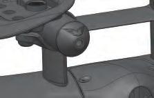
13 Step 6 a. Continue inserting the Di2 BatPac Assembly into the IA frame as shown below. b. Once BatPac Assembly is in place as shown (fig a), fasten shut with provided M3 x 10mm bolts. fig. a 1 Electronic Wiring -13-

14 Step 7 Install front and rear derailleurs and plug Shimano Di2 Wires firmly into the respective derailleurs as shown. 1 Electronic Wiring -14-


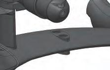
15 Step 8 Wire Grommets a. Press in any remaining grommets. Refer to below images for placement. b. If not already done, connect wires to derailleurs and Junction B. A B A B 1 Electronic Wiring Rear Derailleur Grommet Front Derailleur Grommet -15-
16 Section 2: Mechanical Cabling 2 Mechanical Cabling -16-


17 Mechanical Cabling Road Map Rear Derailleur Cable to Shifter Front Derailleur Cable to Shifter Rear Brake Cable to Brake Lever 2 Mechanical Cabling -17-
 2 Mechanical Cabling 4. Derailleur Cable Housing 5. Derailleur Cables 6.")
18 Mechanical Cabling Parts BatPac/ Front Derailleur Housing Stop 2. Front Derailleur Frame Grommet 3. Rear Dropout Cable Grommet (5mm) 2 Mechanical Cabling 4. Derailleur Cable Housing 5. Derailleur Cables 6. BatPac Bolt (x2) M3 x 10mm -18-


19 Step 1 Mechanical Cabling Begin by routing a length of Derailleur Cable Housing through the Cable Routing Insertion Area, into the downtube. Mechanical Cable Tip: to make routing easier, tape the end of the cable to the end of a second brake cable. Once the first cable is visible through the exit hole, pull through and remove tape. Both ends of the second cable should be visible exiting the frame. 2 Mechanical Cabling -19-
 (fig. a) c.")
20 Step 2 a. Route a length of Derailleur Cable into the head tube, through the downtube, under the bottom bracket and out the rear brake hole. (fig. a) b. Route the Derailleur Cable through the right dropout hole, right chainstay, and out the rear brake hole. (fig. b) (fig. a) c. Bring end of Derailleur Cable Housing and the Derailleur Cable (both of which which just exited the rear brake hole), and by inserting the cable into the Rear Derailleur Cable Housing, advance the cable housing through the frame until it is visible through top tube exit port. (fig. b) 2 Mechanical Cabling -20-

 b. Route the Front Derailleur Cable")


21 Step 3 a. The Rear Derailleur Cable Housing installation is shown below. (fig. a) b. Route the Front Derailleur Cable Housing through the Routing Insertion Area, down the downtube and out the rear brake hole. (fig. b) c. Then route the end of the Front Derailleur Cable out of the hole between the chainstays as illustrated below. (fig. c) (fig. a) (fig. c (fig. b 2 Mechanical Cabling -21-


22 Step 4 Install Cable Stop a. Feed a ferrule over the Derailleur Cable and press onto the Derailleur Housing. a. Feed the exposed Front Derailleur Cable throught the Front Derailleur Cable Stop as pictured. Be sure the end of the Front Derailleur Cable Housing fits snugly into the hole of the Cable Stop. 2 Mechanical Cabling -22-


 c. Install front")

23 Step 5 a. Fit Front Derailleur Cable Housing Stop into the frame as pictued. Fasten securely with provided M3 bolts. Tighten to 2Nm. b. Install Front Derailleur r Frame Grommet. (fig. a) c. Install front derailleur and attach Front Derailleur eur Cable. (fig. b) fig. a fig. b 2 Mechanical Cabling -23-


 b. Install rear")


24 Step 6 a. Fit Rear Dropout Cable Grommet as shown. (5mm conical)be sure to press securely into frame. (fig. a) b. Install rear derailleur and plug Rear Derailleur Cable Housing into derailleur. (fig. b) fig. b fig. a 2 Mechanical Cabling -24-
25 Section 3: Fork Installation 3 Fork Assembly -25-

26 Fork Installation Instructions IA Fork 2. Lower Headset Bearing 3. Upper Headset Bearing 3 Fork Assembly 4. Upper Headset Race 5. Carbon Compression Plug -26-

27 Fork & Headset Installation Step 1 a. Install the Carbon Compression Plug into the fork steerer tube and tighten to 5Nm. b. Slide the lower headset bearing over the fork steerer tube and push down onto the fork crown. 3 Fork Assembly Note: The fork has an integrated crown race. -27-


28 Step 2 a. Slide fork steerer tube through frame s head tube as shown. 3 Fork Assembly -28-

29 Step 3 a. Install upper headset bearing and Headset Race as shown below. 3 Fork Assembly -29-
30 Section 4: Stem Installation 4 Stem -30-
 7. 15mm Stem Spacer (Used with 40mm Bolt) 8. Handlebar Bolt - 55mm M6 (x4) 9. 30mm Stem Spacer (Used with 55mm Bolt) -31-")
31 Stem Installation Parts Stem 1. Headset Preload Bolt 2. Fit Washer (x4) 3. Stem Top Cap 4. Handlebar Bolt - 25mm M6 (x4) 5. Stem 6. Handlebar Bolt - 40mm M6 (x4) 7. 15mm Stem Spacer (Used with 40mm Bolt) 8. Handlebar Bolt - 55mm M6 (x4) 9. 30mm Stem Spacer (Used with 55mm Bolt) -31-


 b.")

32 fig. a Step 1 Stem Installation a. Once Fork is installed, slide the Stem onto steerer tube, then place the Top Cap and tighten the Preload Bolt as needed to eliminate play in the headset. (fig. a & fig. b) b. Tighten pinch bolts to 6Nm. (fig. c) fig. c fig. b 4 Stem -32-
33 Section 5: Aerobar Installation 5 Aero Bar -33-
 2. Basebar Plate 3. Basebar -34-")
34 Section 5 Pt. 1: Basebar Routing Instructions Aero Bar 1. Basebar Plate Bolt (M3 x 10mm) 2. Basebar Plate 3. Basebar -34-


 Once cable is visible")


35 Step 1 Route Di2 Wire Route Rear Shimano Di2 Shifter Wire through the Aero Basebar as shown. Electronic Wire Tip: to make routing easier, tape the end of the wire to the end of a material that is easier to route than a wire or housing. (we used a blue plastic tubing for this example) Once cable is visible through exit hole, pull through and remove tape. Step 9 Insert end of Shimano Di2 Wire into appropriate hole in Basebar as shown and pull back out through main grip opening. 5 Aero Bar -35-

 b.")


36 Step 2 Pull Di2 Wire Through Bar a. As previously mentioned, tape end of Shimano Di2 wire to tube or brake cable. (fig. a) b. Carefully pull through the bar until the taped end exits the basebar. (Remove tape and tube or cable used to route with.) fig. a 5 Aero Bar -36-


37 Step 3 Route Brake Housing In similar fashion to the way we previously routed the Di2 wire, we will use a brake cable to assist in routing the Brake Cable Housing. a. Route the end of a brake cable through the hole where the basebar mounts to the stem and out the right handle. (fig. a) b. Slide Brake Housing over exposed end of brake cable (which just exited the right handle) and advance it through the basebar. (fig. b) fig. a fig. b 5 Aero Bar -37-


38 Step 4 After Brake Cable Housing is routed, remove the cable which was used to route the Brake Cable Housing as pictured. Step 5 a. Plug handlebar end of Brake Cable Housing into Brake Lever and install Brake Lever into handlebar. b. Repeat the previous 4 steps to finish Brake Cable Housing and Di2 Wire for left side of basebar. 5 Aero Bar -38-


39 Step 6 Basebar Routed Both Di2 Wires and Brake Cable Housing are shown routed through the Basebar properly. To Rear Brake To Front Brake * Note: Front Brake Cable Housing exposed length will vary. Trim after verifying necessary length required to reach front brake when basebar is properly mounted. 5 Aero Bar -39-

 into")

 c.")

40 Step 7 Barrel Adjuster Installation a. Insert the rear brake housing (which exits the basebar) into the large opening of Barrel Adjuster. b. Insert Stepdown Ferrule into Barrel Adjuster as shown. (fig. a.) c. Insert Rear Brake Housing (rear brake bound into Stepdown Ferrule. fig. a To Rear Brake To Rear Brake Lever 5 Aero Bar -40-


41 Step 8 Plug Wires Into Junction A a. The following Di2 wires plug into the Shimano Di2 Junction A: - Front Brake Lever - Front Derailleur Shifter - Rear Brake Lever - Rear Derailleur Shifter - Junction B 5 Aero Bar -41-

42 Step 9 Basebar Plate Place Aerobar Basebar Plate onto the basebar and tighten bolts as shown to 2Nm. 5 Aero Bar -42-
43 Section 5 Pt. 2: Aerobar Assembly Parts List QTY. SIZE - PART NAME PART 4 M6 x 55mm - Bolt 4 M6 x 50mm - Bolt 4 M6 x 45mm - Bolt 4 M6 x 40mm - Bolt 4 M6 x 35mm - Bolt 8 M6 x 30mm - Bolt 4 M6 x 25mm - Bolt 4 M6 x 20mm - Bolt 2 M6 x 15mm - Bolt 5 Aero Bar 4 2 M5 x 12mm - Bolt M3 x 10mm - Bolt -43-
44 QTY. SIZE - PART NAME PART 1 Basebar 2 Extension 2 Extension Plug 2 Extension Bracket 2 Armrest Bracket 1 Narrow Fixed Bridge 1 Wide Fixed Bridge 5 Aero Bar 2 Armrest -44-

45 QTY. SIZE - PART NAME PART QTY. SIZE - PART NAME PART 40 Fit Washer 2 Bracket Spacer 1 Basebar Plate 2 Armrest Washer 2 Threaded Lower Nut QTY SIZE 40mm 30mm 20mm 10mm 5mm PART Threaded Spacer Threaded Spacer Threaded Spacer Non-Threaded Spacer Non-Threaded Spacer 5 Aero Bar -45-


46 Adjustability The below reference highlights the five main areas of adjustment that can be manipulated to achieve the desired configuration. 5 Aero Bar 1. Armpad position & angle 2. Armpad fore & aft 3. Armpad width 4. Extension width & angle 5. Extension fore & aft 6. Stack height -46-


47 For riders who prefer a narrower position, further adjustment can be achieved by flipping the extension brackets 180 degrees to position the extensions closer together. See the two images below for demonstration. See details below for additional clarity. 5 Aero Bar -47-


48 Shown below is an example of a high-stack configuration with a narrow armpad and extension position which utilizes a narrow fixed bridge for stability. Narrow Fixed Bridge 5 Aero Bar -48-
49 tt Section 5: Pt. 3 Aerobar Configuration Chart If you know the dimensions that you require while riding a TRI bicycle, the chart below will help you quickly identify the hardware required to achieve your desired stack height. Use only the specific parts listed for your desired stack height. Using any combination of parts other than those specified can result in suboptimal performance, including causing the bracket or the aerobar to come loose or even break. 5 Aero If Bar you do not know the dimensions you require, Felt recommends getting fitted by a qualified fit specialist. Outer Stack Height (c-c) Inner Stack Height (c-c) Threaded Spacer Non-threaded config. Fit Washers Top Bolts (mm) Bottom Bolts (mm) X 5mm 4 45 X X 10mm 4 50 X X 5mm + 10mm 6 55 X X mm Fixed Bridge X Fixed Bridge + 5mm Fixed Bridge Fixed Bridge + 5mm Fixed Bridge Fixed Bridge + 5mm Fixed Bridge + 10mm Fixed Bridge + 10mm + 5mm Threaded lower nut Notes: When calculating stack height measurement: As the IA uses an integrated stem, the center of the stem is equivalent to that of conventional 70mm X -7 degree stem. An assembly with stack height of 53mm will be used as an example in the following instructions. -49-
 Threaded Spacer")
 Threaded")


50 Stack Height & Riser Assembly Option A Inner Stack Height (c-c) Threaded Spacer Non-threaded Config. Fit Washers Top Bolts (mm) Threaded Lower Nut Bottom Bolts (mm) 36 X 5mm +10mm 4 55 X 1 - One extension - Two top bolts (55mm) - One extension bracket - One bracket spacer* - Stack height spacers (5mm + 10mm) - Fit washers (6)** - One threaded lower nut Option A. The diagram to the left is a low-stack configuration and does NOT require the narrow fixed bridge. Use this example to assist in building low-stack assemblies. Tighten the 2 bolts to 6Nm. 5 Aero Bar -50-
 Bottom Bolts (mm) Threaded Lower Nut 56 30 Fixed Bridge 6")
** - Threaded spacers (30mm) - Bottom")


51 Option B Inner Stack Height (c-c) Threaded Spacer Non-threaded Config. Fit Washers Top Bolts (mm) Bottom Bolts (mm) Threaded Lower Nut Fixed Bridge One Extension - Two top bolts (30mm) - One bracket spacer * - One extension bracket - Narrow fixed bridge - Fit washers (6)** - Threaded spacers (30mm) - Bottom bolts X 5 Aero Bar Option B. The diagram to the left is a high-stack configuration and does require the narrow fixed bridge and a total of 4 bolts. The of the bolts enter the underside of the basebar and thread into the threaded spacer, and 2 top bolts enter the extension bracket and thread into the threaded spacer. Tighten all 4 bolts to 6Nm. -51-


52 Important! *BRACKET SPACER Insert the bracket spacer into the slot located on the extension bracket, making sure to align the holes and leave the long, curved edge flush with the edge of the extenion bracket slot as shown in the illustration to the right. **FIT WASHERS Begin with pressing the fit washers into the recessed holes. Sandwich the fit washer between the bolt, spacer/bridge and a threaded spacer. Tighten the bolt until the fit washer is pressed in. Unthread the bolt and assemble. Threaded spacer Threaded lower nut 5 Aero Bar -52-


53 Arm Rest Assembly To complete the arm rest assembly, you will need the following: - Two 12mm Arm Rest Bolts - One Arm Rest Washer - One Arm Rest - One Arm Rest Bracket - One 15mm Bolt Begin by taking an arm rest bracket and thread a 15mm bolt into the underside and finger-tighten to keep in place. Place the arm rest washer and use two arm rest bolts to fasten in desired position. Finally, slip the arm rest assembly over the extension and tighten the 15mm bolt to 7Nm. DO NOT OVERTIGHTEN, as this can affect the structural integrity of the assembly and the aerobar. See diagram on following page for the four acceptable configurations. Possible armrest configurations 5 Aero Bar -53-

.")
54 Notice that the diameters of the six holes in the arm rest are each larger than the diameter of the bolt shaft. This allows for fine-tuning to achieve desired arm pad angle. See below for illustrations. The image below shows the stack assembly and arm rest assembly properly mounted on an extension (actual placement of assemblies in relation to the extension will vary). Counter-Clockwise Rotation Clockwise Rotation 5 Aero Bar -54-

55 Section 6: Felt Aero Brake System 6 Brake Installation -55-
 8. 30mm Brake Mounting Screw 9. Backing Plate 10. Brake Pad & Brake Pad Holder (x2) 11. Left Brake Arm 12.")
56 Felt Aero Brake System Parts Right Brake Arm 2. Return Spring 3. Front Plate Mounting Screw (x2) 4. Carriage Assembly 5. Brake Mounting Bolt 6. Front Plate 6 Brake Installation 7. Brake Arm IGUS Pivot Bushing (x4) 8. 30mm Brake Mounting Screw 9. Backing Plate 10. Brake Pad & Brake Pad Holder (x2) 11. Left Brake Arm 12. Brake Pad Spherical Washer (x2) 13. 1mm Thick Pad Spacer Washer (x2) 14. Brake Shoe Fixing Washer (x2) 15. Brake Shoe Fixing Screw (x2) 16. Track Mounting Screw (x2) 17. Track 18. Cable Noodle 19. Cable Barrel Adjuster -56-


57 Felt Aero Brake System Torque Values No a 3b 4a 5 Part Description Front Plate Mounting Screw Track Mounting Screw Front Brake Mounting Screw Front Brake Mounting Nut Rear Brake Mounting Screw Cable Clamping Screw Thread M4 x 0.7 M3 x 0.5 M6 x 1.0 M6 x 1.0 M6 x 1.0 M4 x 0.7 Allen Key Size 3mm 2mm 4mm 5mm 4mm 2mm Recommended Torque 2 Nm 1Nm 6-8Nm 6-8Nm 6-8Nm 1Nm 5 3b 2 1 3a & 4a 6 Brake Installation -57-


58 Felt Aero Brake System Disassembly Step 1: Begin by removing Cable Barrel Adjuster, Noodle, Brake Pad Assemblies and Mounting Screw. 6 Brake Installation Step 2: After Removal of initial parts, the remaining brake should look as the sample above does. Step 3: Remove Front Plate and Mounting Screws. -58-


59 Step 4: Remove Carriage Assembly. Step 5: Remove Brake Arms, Mounting Bolt and Spring. Step 6: Remove Track from Backing Plate. 6 Brake Installation -59-


60 Felt Aero Brake System Cleaning and Inspection Cam Surface Step 1: Clean and Inspect Brake Carriage Assembly Rollers and T-Slot 6 Brake Installation Step 2: Clean and Inspect Brake Arm Cam Surfaces and Spring Pocket Step 3: Clean and Inspect Brake Arm Bushings. -60-

61 Cleaners: The Brake Pivots and Cam Follower Rollers incorporate IGUS lubrication-free polymer bushings, which DO NOT require any form of lubricant to function properly. It should be noted that if these bushings are exposed to harsh chemical cleaners, aerosol cleaners, solvents, or lubricants, they may experience a chemical reaction causing the bushings to swell up and bind and/or eventually break down. (Notes: WD-40 is particularly harmful to these bushings. Petroleum-based prouducts are okay to use. Typically, aerosol cleaners are not acceptable.) It Is recommended that the brake be cleaned with a mild degreaser or soap and water. Lubricants: As previously noted, the Brake Pivots and Cam Follower Roller Bushings are lubricant-free, and DO NOT require any form of lubricant to function properly. Step 4:Clean and Inspect Spring 6 Brake Installation Step 5: Clean Brake Arm Pivots A Light Waterproof Grease may be applied to the Brake Arm Cam Track and to the Carriage Track if desired. -61-


62 Felt Aero Brake System Reassembly Cam Surface Step 1: Remount Track and apply film of light, waterproof grease. Tighten bolts to 1Nm. 6 Brake Installation Step 2: Apply a thin film of light waterproof grease to Brake Arm Cam surfaces. Step 3: Apply thin film of light waterproof grease to spring arms. -62-


63 Step 4: Preassemble Brake Arms and Spring. 6 Brake Installation Step 5: Add Bushings to Brake Arms. Slip Brake Arm and Spring Preassembly onto Brake Posts. Add Brake Mount Bolt Step 6: Install Carriage Assembly followed by installing the Front Plate and tighten screws to 2Nm. -63-


64 Section 6 Pt. 1: Felt Aero Brake Front Assembly Step 1 Install Front Brake Fasten the Front Brake to the fork using the Brake Mouting Bolt and the 30mm Brake Mouting Nut and Serrated Nut as shown. 6 Brake Installation -64-

65 Step 2 Tighten Brake Bolts Using a 4mm and 5mm Hex Wrench, tighten the Brake Mouting Nut and Bolt to 6Nm. 6 Brake Installation -65-

66 Step 3 Thread the Front Brake Cable through the Front Brake Cable Housing, through the Barrel Adjuster and into the Front Brake as shown. 6 Brake Installation -66-


 fig.")
67 Step 4 Secure Brake Cable Apply tension on the front brake cable and tighten the Cable Clamping Screw as shown. (fig. a) fig. a 6 Brake Installation -67-

68 Section 6 Pt. 2: Front Brake Cover Installation Brake Installation 1. Lower Front Brake Cover 2. Brake Cover Bolt 3. Upper Front Brake Cover -68-

 fig. b b.")
69 fig. a Step 1 Add Lower Cover a. In order to make Di2 Wires easier to manage, it is recommended that a cable tie be used to affix wires to Junction A as pictured. (fig. a) fig. b b. Place Lower Front Brake Cover. (fig. b) 6 Brake Installation -69-

70 Step 2 Add Upper Cover a. Place the Upper Front Brake Cover as shown. b. Secure both Lower and Upper Brake Cover with M3 bolts tightened to 2Nm. 6 Brake Installation -70-


 b.")

71 Section 6 Pt. 3: Felt Aero Brake Rear Assembly Step 1 Rear Brake Installation a. Locate the Rear Brake Cable Housing currently exiting the hole under the bottom bracket. (fig. a) b. Insert a flexible guide noodle onto Rear Brake Cable Housing and install Rear Brake Cable. fig. a fig. b 6 Brake Installation -71-


72 Step 2 Install Brake a. Thread the Rear Brake Cable Into the Rear Brake as shown. (fig. a) b. Mount the rear brake by tightening M 6 bolt to 6Nm. (fig. b) fig. b fig. a 6 Brake Installation -72-


73 Step 3 a. Trim Excess brake cable and install a cable crimp as shown. 6 Brake Installation -73-

74 Step 4 Install Brake Cover a. Orient the brake cover as shown and tighten included M3 bolts to 2Nm. 6 Brake Installation -74-
75 Section 7: Seatpost Installation 7 Seatpost Assembly -75-

76 VR Seatpost Parts Seatpost 1. VR Seatpost 2. 3T Difflock End-Cap 3. 3T DiffLock M5 Bolts/star washers (x2) 4. 3T Difflock Inner Spline Suppport Assembly 5. 3T Difflock Outer Spline 6. InternaLoc Seatpost Wedge 7. Compression Spring 8. Seatpost Seals 9. Internaloc Seatpost Bolts -76-


 c.")

 7 Seatpost fig.")
77 Step 1 Internaloc Seatpost Wedge Assembly a. Place Compression Spring between Internaloc Seatpost Wedges. (fig. a) b. Place Internaloc Seatpost Wedge on top of other wedge, sandwiching the Compression Spring. (fig. b) c. Make sure spring is alined with seatpost wedges. (fig. c) 7 Seatpost fig. a fig. b fig. c Assembly -77-

 e.")


78 Step 2 d. After the Compression Spring is installed in the two halves of the InternaLoc Seatpost Wedge, orient the seatpost so the bottom edge will slant downward toward the ground at the front of the bike. (fig. d) e. Apply a thin coat of carbon friction paste on the surface of aluminum InternaLoc Seatpost Wedge that will contact the carbon fiber surface of seatpost to prevent slipping or noise. (fig.e) fig. e f. Slide the assembly up into the seatpost until the guides on each side of the internal seatpost wedge snap into the slots on each side of the seatpost. Be sure to keep the assembly at the bottom of the seatpost for now. (fig. f) fig. d click! 7 Seatpost Assembly fig. f -78-


 c.")
 fig. b d.")
79 fig. a Step 2 a. Insert the 3T Difflock Outer Spline into VR seatpost seat clamp area. (fig. a) b. Insert the 3T Difflock Inner Spline Support into the 3T Difflock Outer Spline. (fig. b) c. Insert 3T Difflock End-Cap and M5 Bolt. (fig. c) fig. b d. Partially tighten with 4mm Allen Wrench. (fig. d) fig. c 7 Seatpost Assembly fig. d -79-


 b.")


 d. After determining")


 e.")
80 fig. a fig. b 7 Seatpost Step 2 a. If not done yet, press-fit the Seatpost Seals into the VR Seatpost Slot. (fig. a) b. Apply a thin coat of carbon friction paste on the surface of Seatpost to insertion point and inside seat tube to prevent slipping or noise. (fig. a) Assembly c. Insert seatpost into frame, thread seatpost binder bolts, but do not tighten completly. (fig. b) d. After determining appropriate seatpost insertion, trim silicone slot cover so exposed seatpost slot is entirely covered by slot cover. (fig. b) e. After making sure slot cover is entirely covered, tighten seatpost binder bolts to 7Nm. -80-
81 Section 8: CalPac / AeroPac Installation 8 Calpac -81-

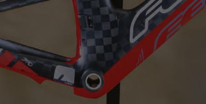
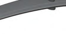
82 Step 1 Install CalPac Cover Once the protrusions of the Calpac are aligned with the cavities located on the underside of the AeroPac, press the AeroPac firmly into place. 8 Calpac -82-

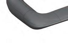
83 Step 2 AeroPac Properly Installed Be sure the CalPac is properly installed. There should be no significant gap between the CalPac and AeroPac cover. Once installed, it should appear as pictured. (fig. a) fig. a 8 Calpac -83-

84 Complete The IA is shown with CalPac, Fork, Headset, Stem, Aerobars, Brakes, Brake Covers Installed and all Brake Cables and Shimano Di2 Wires Routed. Should you ever need further clarification, or do not feel entirely confident performing manintenance on your IA, please contact your local Felt Dealer for help. Thank you for your support and ride safely! -84-
85
SECTION 1 UNPACKING INSTRUCTIONS
 ANDEAN USER GUIDE SECTION 1 UNPACKING INSTRUCTIONS 2 REMOVE PART BOX, ACCESSORY BOX AND SADDLE AND SEATPOST. SET ACCESORIES AND SEAT ASIDE FOR FINAL. PARTS BOX ACCESORY BOX 3 UNSTRAP WHEEL BLOCKS AND HANDLEBAR
ROAD DISC TECHNICAL MANUAL
 ROAD DISC TECHNICAL MANUAL INTRODUCTION Congratulations on purchasing a Felt disc brake equipped road bike. As with all of our bikes and components, our aim is to provide the rider with the best product
TABLE OF CONTENTS FRAME FEATURES INTRODUCTION
 S3 DISC MANUAL TABLE OF CONTENTS Introduction...1 Frame Features...2 Fork Preparation...3 Small Parts...5 Frame Preparation...6 Brake Housing Installation...7 Mechanical Cable Routing...9 Electric Cable
2019 MADONE ASSEMBLY MANUAL
 2019 MADONE ASSEMBLY MANUAL 2019 MADONE Rim brakes and Di2 drivetrain Rim brakes and mechanical drivetrain Disc brakes and Di2 drivetrain Disc brakes and mechanical drivetrain TABLE OF CONTENTS Common
2019 MADONE ASSEMBLY MANUAL
 2019 MADONE ASSEMBLY MANUAL 2019 MADONE Rim brakes and Di2 drivetrain Disc brakes and Di2 drivetrain Rim brakes and mechanical drivetrain Disc brakes and mechanical drivetrain TABLE OF CONTENTS Common
E-118 Assembly Guide
 E-118 Assembly Guide Table of Contents Overview of the assembly.... 2 1. Fork installation.... 3-4 2. Cable housing installation.... 5 3. Handlebar installation... 6 4. Front brake installation.... 7-8
Shimano Di2 Installation on S5
 Installing Shimano Dura Ace Di2 Shifting Systems Note these instructions and pictures are for assembling the Shimano Dura Ace Di2 system (Internal Spec) on the Cervélo S5 frame. The Shimano Ultegra Di2
GALLIUM PRO: ASSEMBLY GUIDE
 GALLIUM PRO: ASSEMBLY GUIDE Revision 2.0-04-08-2016 GALLIUM PRO : Table of contents Assembly overview..........................2-3 1. Frame inspection........................4 2. Headset installation.......................5
GALLIUM: ASSEMBLY GUIDE
 GALLIUM: ASSEMBLY GUIDE Revision 2.0-04-08-206 GALLIUM: Table of contents Assembly overview..........................2. Frame inspection........................3 2. Headset installation.......................4
FRAME FEATURES TABLE OF CONTENTS INTRODUCTION
 R3 MANUAL TABLE OF CONTENTS Introduction...1 Frame Features...2 Fork Preparation...3 Small Parts...5 Frame Preparation...6 Mechanical Cable Routing...7 Electric Cable Routing...9 Seatpost Assembly & Installation...11
E-116 Assembly Guide
 E-116 Assembly Guide Table of Contents Overview of the assembly.... 2 1. Cable housing installation.... 3 2. Front brake installation.... 4 3. Rear brake installation... 5-6 4. Seatpost installation....
TABLE OF CONTENTS INTRODUCTION
 R3 DISC MANUAL TABLE OF CONTENTS Introduction... 1 Frame Features... 2 Fork Preparation... 3 Small Parts... 5 Frame Preparation... 6 Brake Housing Installation... 7 Mechanical Cable Routing... 9 Electric
NITROGEN DISC 286A: ASSEMBLY GUIDE
 NITROGEN DISC 286A: ASSEMBLY GUIDE Valid for MY2019 Nitrogen Disc 286A Revision 1.0-07-26-2018 NITROGEN DISC 286A: Table of Contents 1. Tools Needed and First Aid Kit...3 2. Frameset inspection...4 3.
KRYPTON X ROAD : ASSEMBLY GUIDE
 KRYPTON X ROAD : ASSEMBLY GUIDE Revision 3.0-06-01-2016 KRYPTON X ROAD : Table of contents Assembly overview.........................2 1. Frame inspection........................3 2. Headset installation.......................4
R5 RIM MANUAL EN. Version 1 I
 R5 RIM MANUAL EN Version 1 I 28.04.2017 TABLE OF CONTENTS Introduction...1 Frame Features...2 Fork Preparation...3 Small Parts...5 Frame Preparation...6 Mechanical Cable Routing...7 Electric Cable Routing...9
R3 RIM MANUAL EN. Version 1 I
 R3 RIM MANUAL EN Version 1 I 07.02.2017 TABLE OF CONTENTS Introduction...1 Frame Features...2 Fork Preparation...3 Small Parts...5 Frame Preparation...6 Mechanical Cable Routing...7 Electric Cable Routing...9
R5 DISC MANUAL EN. Version 1 I
 R5 DISC MANUAL EN Version 1 I 30.04.2017 TABLE OF CONTENTS Introduction...1 Frame Features...2 Fork Preparation...3 Small Parts...5 Frame Preparation...6 Brake Housing Installation...7 Mechanical Cable
Final Assembly Instructions Bikes with Threaded Headsets
 Final Assembly Instructions Bikes with Threaded Headsets Thank you for buying your new bicycle from L.L.Bean. Read these instructions carefully before beginning the final assembly. Prior to shipping, our
E-trike Li Assembly Guide
 PREPARATION 1. Read this assembly manual BEFORE commencing assembly. 2. Carefully remove all the components and packaged hardware from the shipping boxes. 3. Unpack the contents of the large double box
GALLIUM CS 281A: ASSEMBLY GUIDE. Revision Valid for MY2019 Gallium CS
 GALLIUM CS 281A: ASSEMBLY GUIDE Revision 0.0-2018-05-04 - Valid for MY2019 Gallium CS GALLIUM CS 281B: ASSEMBLY GUIDE Revision 0.0-2018-05-04 - Valid for MY2019 Gallium CS GALLIUM CS 281A / 281B: Table
FRAME FEATURES TABLE OF CONTENTS INTRODUCTION. A guide to your Cervélo C Series frame.
 C SERIES MANUAL TABLE OF CONTENTS Introduction...1 Frame Features...2 Fork Preparation...3 Small Parts...5 Frame Preparation...6 Brake Housing Installation...7 Mechanical Cable Routing...9 Electric Cable
Final Assembly Instructions Bikes with Quill Stems
 Final Assembly Instructions Bikes with Quill Stems Thank you for buying your new bicycle from L.L.Bean. Read these instructions carefully before beginning the final assembly. Prior to shipping, our expert
ELECTRON PRO 245A: ASSEMBLY GUIDE. Revision Valid for MY2017 Electron Pro
 ELECTRON PRO 245A: ASSEMBLY GUIDE Revision 2.0 04-19-2017 Valid for MY2017 Electron Pro ELECTRON PRO 245A: Table of Contents 1. Tools Needed and First Aid Kit...3 2. Specifications...4 3. Configurations...5
GALLIUM PRO 210A: ASSEMBLY GUIDE
 GALLIUM PRO 210A: ASSEMBLY GUIDE Revision 5.0-05-23-2017 GALLIUM PRO 210A: Table of contents Assembly overview...2-3 1. Frame inspection...4 2. Headset installation...5 3. Cables & housing installation...6-9
Final Assembly Instructions Bikes with 16 Wheel Size
 Final Assembly Instructions Bikes with 16 Wheel Size Thank you for buying your new bicycle from L.L.Bean. Read these instructions carefully before beginning the final assembly. Prior to shipping, our expert
INSTRUCTION GUIDE TRANSITION CARBON (ALL MODELS)
") INSTRUCTION GUIDE TRANSITION CARBON (ALL MODELS) THIS INSTRUCTION GUIDE CONTAINS IMPORTANT INFORMATION. PLEASE READ CAREFULLY AND STORE IN A SAFE PLACE. Congratulations! The Specialized bicycle you have
INSTRUCTION GUIDE TRANSITION CARBON (ALL MODELS) THIS INSTRUCTION GUIDE CONTAINS IMPORTANT INFORMATION. PLEASE READ CAREFULLY AND STORE IN A SAFE PLACE. Congratulations! The Specialized bicycle you have
E-117 TRI: ASSEMBLY GUIDE
 E-117 TRI: ASSEMBLY GUIDE Valid for MY2016 E-117 Tri Revision 8.0-07-08-2016 E-117 TRI: Table of Contents 1. Tools Needed & First Ait Kit..........................2 2. Fitting / Stack & Reach.....................3
1. General Safety Information. Silvio V2.2 Assembly Instructions Assembly. Adjust to the rider.
 Silvio V. Assembly Instructions support@cruzbike.com. General Safety Information WARNING to avoid serious injuries:. If you are unsure about fitting, testing and adjusting brakes or gearing on a bicycle,
Final Assembly Instructions Bikes with Threaded Headsets
 Final Assembly Instructions Bikes with Threaded Headsets Thank you for buying your new bicycle from L.L.Bean. Read these instructions carefully before beginning the final assembly. Prior to shipping, our
Rocky Mountain Element Technical Manual. Rev B
 Rocky Mountain Element Technical Manual Rev B 1 Table of Contents Materials Required... 3 Suspension Pivot Torque Guide... 4 Small Parts Torque Guide... 5 Assembly Instructions... 6 1) Bearing Installation...
KRYPTON X ROAD : ASSEMBLY GUIDE
 KRYPTON X ROAD : ASSEMBLY GUIDE KRYPTON X ROAD : Table of contents Assembly overview.........................2 1. Frame inspection........................3 2. Headset installation.......................4
NITROGEN: ASSEMBLY GUIDE
 NITROGEN: ASSEMBLY GUIDE Valid for MY2016 Nitrogen Revision 3.0-04-01-2016 NITROGEN: Table of contents Overview of the assembly..........................2-3 1. Frame inspection........................4
Assembly Tools. Assembly will take about an hour
 Assembly Guide Assembly Tools Included in your parts box: Pedals Toolkit (4+5mm combo Allen wrench, 13+15mm combo open-end wrench) Touch-up paint Spare fuses (for battery) Assembly will take about an hour
Santa Fe Cycles Assembly Guide Introduction
 Santa Fe Cycles Assembly Guide Introduction Congratulations on your purchase of your new Santa Fe bicycle. You have purchased a bicycle that has many features and qualities. Please take a few minutes and
ST Shimano Total Integration. Technical Service Instructions. General Safety Information SI-6CT0B
 Technical Service Instructions SI-6CT0B t ST-4400 Shimano Total Integration Shimano Total Integration Features The Shimano Total Integration TIAGRA series features a dual action control lever which actuates
TIMEMACHINE. Assembly Manual
 TIMEMACHINE Assembly Manual TIMEMACHINE Assembly Instruction Manual The new Timemachine 01 represents the pinnacle of functional integration, aerodynamic form and rider-focused fit. By patiently following
ELECTRON PRO: ASSEMBLY GUIDE. Revision Valid for MY2017 Electron Pro
 ELECTRON PRO: ASSEMBLY GUIDE Revision 1.0 10-20-2016 Valid for MY2017 Electron Pro ELECTRON PRO: Table of Contents 1. Tools Needed and First Aid Kit...3 2. Specifications...4 3. Configurations...5 4. Geometry...7
VR SERIES TECHNICAL MANUAL
 VR SERIES TECHNICAL MANUAL INTRODUCTION CONTENTS VR SERIES Congratulations on purchasing a VR Series. As with all of our bikes and components, our aim is to provide the rider with the best product and
GALLIUM PRO : ASSEMBLY GUIDE
 GALLIUM PRO : ASSEMBLY GUIDE GALLIUM PRO : Table of contents Assembly overview..........................2-3 1. Frame inspection........................4 2. Headset installation.......................5
RADON 237A: ASSEMBLY GUIDE. Revision Valid for MY2017 Radon
 RADON 237A: ASSEMBLY GUIDE Revision 3.0-05-29-2017 - Valid for MY2017 Radon RADON 237A: Table of Contents 1. Tools Needed and First Aid Kit... 3 2. Sizing Chart... 4 3. Seat Post Collar Assembly... 5 4.
E-119 TRI: ASSEMBLY GUIDE
 E-119 TRI: ASSEMBLY GUIDE Valid for MY2016 E-119 Tri Revision 12.0-07-08-2016 E-119 TRI: Table of Contents 1. Tools Needed & First Ait Kit..........................2 2. Fitting / Stack & Reach.....................3
UNPACKING AND ASSEMBLING YOUR DIAMONDBACK ROAD BIKE
 EMAIL SIGNUP BIKE REG SEARCH BIKES THE RIDE HEALTH FITNESS SKILLS SHOP MAINTENANCE CYCLING 101 RIDERS LIKE YOU TEAMS SUPPORT UNPACKING AND ASSEMBLING YOUR DIAMONDBACK ROAD BIKE 1. Begin by carefully cutting
Assembly Tools. Assembly will take 1-2 hours
 Assembly Tools Included in your parts box: Pedals Quick release skewer Reflectors (if not already installed) Toolkit (4+5mm combo Allen wrench, 13+15mm combo open-end wrench) Helpful Tools: Scissors (for
DM-FD (English) Dealer's Manual. Front derailleur FD-M9000 FD-M9020 FD-M9025 FD-M8000 FD-M8020 FD-M8025 FD-M612 FD-M617 FD-M618 FD-M672
 Dealer's Manual. Front derailleur FD-M9000 FD-M9020 FD-M9025 FD-M8000 FD-M8020 FD-M8025 FD-M612 FD-M617 FD-M618 FD-M672") (English) DM-FD0003-04 Front derailleur Dealer's Manual FD-M9000 FD-M9020 FD-M9025 FD-M8000 FD-M8020 FD-M8025 FD-M612 FD-M617 FD-M618 FD-M672 FD-M677 CONTENTS IMPORTANT NOTICE... 3 TO ENSURE SAFETY...
(English) DM-FD0003-04 Front derailleur Dealer's Manual FD-M9000 FD-M9020 FD-M9025 FD-M8000 FD-M8020 FD-M8025 FD-M612 FD-M617 FD-M618 FD-M672 FD-M677 CONTENTS IMPORTANT NOTICE... 3 TO ENSURE SAFETY...
DM-MARD (English) Dealer's Manual. ROAD MTB Trekking. City Touring/ Comfort Bike REAR DERAILLEUR XTR RD-M9100 RD-M9120
 Dealer's Manual. ROAD MTB Trekking. City Touring/ Comfort Bike REAR DERAILLEUR XTR RD-M9100 RD-M9120") (English) DM-MARD001-00 Dealer's Manual ROAD MTB Trekking City Touring/ Comfort Bike URBAN SPORT E-BIKE REAR DERAILLEUR XTR RD-M9100 RD-M9120 CONTENTS CONTENTS...2 IMPORTANT NOTICE...3 TO ENSURE SAFETY...4
(English) DM-MARD001-00 Dealer's Manual ROAD MTB Trekking City Touring/ Comfort Bike URBAN SPORT E-BIKE REAR DERAILLEUR XTR RD-M9100 RD-M9120 CONTENTS CONTENTS...2 IMPORTANT NOTICE...3 TO ENSURE SAFETY...4
Rocky Mountain Instinct / Pipeline Frame Assembly Guide. Date: March 31, 2017
 Rocky Mountain Instinct / Pipeline Frame Assembly Guide Date: March 31, 2017 1 Table of Contents Front Triangle Preparation... 4 Parts Needed... 4 Instructions... 4 Chain Stay Preparation... 6 Parts Needed...
Front derailleur. Dealer's Manual SORA FD-R3000 FD-R3030 CLARIS FD-R2000 FD-R2030. ROAD MTB Trekking. City Touring/ Comfort Bike DM-RBFD001-01
 (English) DM-RBFD001-01 Dealer's Manual ROAD MTB Trekking City Touring/ Comfort Bike URBAN SPORT E-BIKE Front derailleur SORA FD-R3000 FD-R3030 CLARIS FD-R2000 FD-R2030 CONTENTS IMPORTANT NOTICE... 3 TO
Parts List. 7. Handlebars 8. Grips 9. Handlebar Stem 10. Front Brake 11. Front Wheel 12. Crank 13. Chain
 Woodworm Cruise Parts List 1. Free Wheel with Rear Hub 2. Fenders 3. Fender Stay 4. Quick Release 5. Saddle 6. Seat Post 7. Handlebars 8. Grips 9. Handlebar Stem 10. Front Brake 11. Front Wheel 12. Crank
Have questions? Chat with us live at raleighusa.com or call us at , 8am 5pm PST
 1 2 Have questions? Chat with us live at raleighusa.com or call us at 1-800-251-8435, 8am 5pm PST The bicycle you have purchased is a complex piece of equipment that must be properly assembled and maintained
DM-MBRD (English) Dealer's Manual. ROAD MTB Trekking. City Touring/ Comfort Bike. Rear Derailleur SLX RD-M7000 DEORE RD-M6000
 Dealer's Manual. ROAD MTB Trekking. City Touring/ Comfort Bike. Rear Derailleur SLX RD-M7000 DEORE RD-M6000") (English) DM-MBRD001-04 Dealer's Manual ROAD MTB Trekking City Touring/ Comfort Bike URBAN SPORT E-BIKE Rear Derailleur SLX RD-M7000 DEORE RD-M6000 CONTENTS IMPORTANT NOTICE... 3 TO ENSURE SAFETY... 4
(English) DM-MBRD001-04 Dealer's Manual ROAD MTB Trekking City Touring/ Comfort Bike URBAN SPORT E-BIKE Rear Derailleur SLX RD-M7000 DEORE RD-M6000 CONTENTS IMPORTANT NOTICE... 3 TO ENSURE SAFETY... 4
Front derailleur. Dealer's Manual FD-M9000 FD-M9020 FD-M9025 FD-M8000 FD-M8020 FD-M8025 FD-M612 FD-M617 FD-M618 FD-M672 FD-M677
 (English) DM-FD0003-05 Front derailleur Dealer's Manual FD-M9000 FD-M9020 FD-M9025 FD-M8000 FD-M8020 FD-M8025 FD-M612 FD-M617 FD-M618 FD-M672 FD-M677 CONTENTS IMPORTANT NOTICE... 4 TO ENSURE SAFETY...
Rock. ky Altit. ude. Rev B
 Rock ky Mountain Altit ude Technical Manual Date: August 17 th, 2016 Rev B 1 Table of Contents Materials Required... 3 Suspension Pivot Torque Guide... 4 Small Parts Torque Guide... 5 Assembly Instructions...
E-80 : ASSEMBLY GUIDE
 E-80 : ASSEMBLY GUIDE E-80 : Table of contents Assembly overview..........................2 1. Frame inspection........................3 2. Cable housing installation.......................4-7 3. Brakes
CRUZBIKE Quest 2.0 Assembly
 CRUZBIKE Quest 2.0 Assembly CRUZBIKE Quest 2.0 Assembly... 1 General notes on assembly... 2 Un box and evaluate the frame and major parts... 2 Unfold the rear swing arm and arrange the frame... 3 Rear
PRECAUTION INTENDED USE OF THIS MANUAL INTRODUCTION AKING CARE OF
 Table of Contents 1 INTRODUCTION INTDED USE OF THIS MANUAL PRECAUTION TAKING CARE OF YOUR COMPOSITE BICYCLE 5 6 OVERDRIVE HEADSET INSTRUCTION COMPOSITE FRONT FORK 5 7 SPEEDCONTROL BRAKES 6 8 9 10 11 1
FACTORBIKES.COM. Assembly Manual V2.20
 FACTORBIKES.COM V2.20 Introduction I Limited Lifetime Warranty On Bicycles And Framesets I Necessary Tools 01 Instructions 01 1 Seatpost 01 2 Di2 Cable Routing 03 3 Fork - Headset Barstem 05 4 Cutting
Cantilever Brake. Dealer's Manual. ROAD MTB Trekking. City Touring/ Comfort Bike
 (English) DM-RCBR001-00 Dealer's Manual ROAD MTB Trekking City Touring/ Comfort Bike URBAN SPORT E-BIKE Cantilever Brake BR-CX70 BR-CX50 BL-4700 BL-4600 BL-R780 BL-R3000 ST-7900 ST-6700 ST-5700 ST-4600
Shifting Lever. RAPIDFIRE Plus 11-speed
 (English) DM-SL0005-04 Shifting Lever Dealer's Manual RAPIDFIRE Plus 11-speed MTB XTR SL-M9000 DEORE XT SL-M8000 CONTENTS IMPORTANT NOTICE... 3 TO ENSURE SAFETY... 4 LIST OF TOOLS TO BE USED... 7 INSTALLATION...
GALLIUM PRO 259A & 259B: ASSEMBLY GUIDE
 GALLIUM PRO 259A & 259B: ASSEMBLY GUIDE GALLIUM PRO 259A & 259B: Table of Contents 1. Tools Needed and First Aid Kit... 3 2. Sizing Chart... 4 3. Trouble-shooting / Tips... 5 4. Seat Post Collar Assembly...
Front derailleur. Dealer's Manual XTR FD-M9000 FD-M9020 FD-M9025 DEORE XT FD-M8000 FD-M8020 FD-M8025 DEORE FD-M612 FD-M617 FD-M618 SLX FD-M672 FD-M677
 (English) DM-FD0003-06 Dealer's Manual ROAD MTB Trekking City Touring/ Comfort Bike URBAN SPORT E-BIKE Front derailleur XTR FD-M9000 FD-M9020 FD-M9025 DEORE XT FD-M8000 FD-M8020 FD-M8025 DEORE FD-M612
SI-F971A. 9-speed super narrow chain such as CN-7700 / CN-HG92 8- / 7- / 6-speed narrow chain such as CN-HG50 / CN-IG51
 SERVICE INSTRUCTIONS SI-F971A Front Drive System Before use, read these instructions carefully, and follow them for correct use. WARNING Use neutral detergent to clean the chain. Do not use alkali-based
Shifting Lever. Dealer's Manual. RAPIDFIRE Plus SL-M2000 SL-M3010 SL-M4010. Thumb Shifter SL-TZ500. ROAD MTB Trekking. City Touring/ Comfort Bike
 (English) DM-MDSL001-01 Dealer's Manual ROAD MTB Trekking City Touring/ Comfort Bike URBAN SPORT E-BIKE Shifting Lever RAPIDFIRE Plus SL-M2000 SL-M3010 SL-M4010 Thumb Shifter SL-TZ500 CONTENTS IMPORTANT
Dealer's Manual ROAD MTB Trekking City Touring/ URBAN SPORT E-BIKE Comfort Bike Front derailleur ALIVIO Non-Series
 (English) DM-MDFD001-02 Dealer's Manual ROAD MTB Trekking City Touring/ Comfort Bike URBAN SPORT E-BIKE Front derailleur ALIVIO FD-M4000 FD-M4020 Non-Series FD-MT400 CONTENTS IMPORTANT NOTICE... 3 TO ENSURE
Service Information. Speed Concept Note about performing mechanical work on bicycles:
 Service Information Speed Concept 2011 The Trek Speed Concept bike is the fastest frameset we have ever made. To accomplish this, we have used shaped tubes, hidden front and rear brakes, and very thin-walled
SANTANA STOWAWAY TANDEM WITH AIRLINER SAFECASE AND FTS FOAM TRAY SYSTEM ASSEMBLY AND DISASSEMBLY
 SANTANA STOWAWAY TANDEM WITH AIRLINER SAFECASE AND FTS FOAM TRAY SYSTEM ASSEMBLY AND DISASSEMBLY Congratulations! You are now the proud owner of the world s most travel-ready, performance tandem. The following
Have questions? Chat with us live at raleighusa.com or call us at , 8am 5pm PST
 1 2 Have questions? Chat with us live at raleighusa.com or call us at 1-800-251-8435, 8am 5pm PST The bicycle you have purchased is a complex piece of equipment that must be properly assembled and maintained
FACTORBIKES.COM. Assembly Manual DISC V1.05
 FACTORBIKES.COM V1.05 Introduction I Limited Lifetime Warranty On Bicycles And Framesets I Necessary Tools 01 Instructions 01 1 Seatpost 01 2 Cut the cable housing to the correct length 03 3 Di2 Cable
HOME ASSEMBLY INSTRUCTIONS
 HOME ASSEMBLY INSTRUCTIONS This Papillionaire Bicycle now belongs to you. It will take you to work, wait patiently outside your local cafe, and carry your groceries home. This is the start of your long-term
Front derailleur. Dealer's Manual DURA-ACE FD-R9100 ULTEGRA FD-R FD ROAD MTB Trekking. City Touring/ Comfort Bike DM-RAFD001-03
 (English) DM-RAFD001-03 Dealer's Manual ROAD MTB Trekking City Touring/ Comfort Bike URBAN SPORT E-BIKE Front derailleur DURA-ACE FD-R9100 ULTEGRA FD-R8000 105 FD-5801 Procedures for cable tension adjustment
SG-7R46 SG-7R45 BR-IM41-R CJ-7S40 WARNING CAUTION SERVICE INSTRUCTIONS. Inter-7 Hub. Inter-M Brake Cassette joint NOTE:
 t WARNING It is important to completely understand the operation of your bicycle's brake system. Improper use of your bicycle's brake system may result in a loss of control or an accident, which could
E-119 TRI+ 284A: ASSEMBLY GUIDE
 E-119 TRI+ 284A: ASSEMBLY GUIDE Valid for MY2019 E-119 Tri+ Revision 1.0-07-18-2018 E-119 TRI+ 284A: Table of Contents 1. Tools Needed & First Ait Kit..........................2 2. Fitting / Stack & Reach.....................3
Rocky Mountain Instinct / Pipeline Alloy Frame Assembly Guide. Date: April 7, 2017
 Rocky Mountain Instinct / Pipeline Alloy Frame Assembly Guide Date: April 7, 2017 1 Table of Contents Front Triangle Preparation... 4 Parts Needed... 4 Instructions... 4 Chain Stay Preparation... 6 Parts
Lectric Cycles Mid-Drive Electric Motor Installation
 Lectric Cycles Mid-Drive Electric Motor Installation This write-up describes the installation of a Lectric Cycles electric motor. The model is the e-rad Mid-Drive 750 Watt conversion kit, installed on
Rear Drive System SERVICE INSTRUCTION. Specifications SI-R670B
 - SERVICE INSTRUCTION SI-R670B t Rear Drive System Before use, read these instructions carefully, and follow them for correct use. In order to realize the best performance, we recommend that the following
Have questions? Chat with us live at raleighusa.com or call us at , 8am 5pm PST
 1 2 Have questions? Chat with us live at raleighusa.com or call us at 1-800-251-8435, 8am 5pm PST The bicycle you have purchased is a complex piece of equipment that must be properly assembled and maintained
ASSEMBLY GUIDE: Izip & Ezip Electric Bicycles with Rack-Top Mounted Batteries ( RTMB Bicycles )
") ASSEMBLY GUIDE: Izip & Ezip Electric Bicycles with Rack-Top Mounted Batteries ( RTMB Bicycles ) Please Refer to your Owner s Manual for Detailed Setup Instructions Technical & Customer Service: 1-800-377-4532
ASSEMBLY GUIDE: Izip & Ezip Electric Bicycles with Rack-Top Mounted Batteries ( RTMB Bicycles ) Please Refer to your Owner s Manual for Detailed Setup Instructions Technical & Customer Service: 1-800-377-4532
NOAH FAST. frame passport
 frame passport Type: 7DC last update: /08/05 INDEX 0. UPDATES... 3. GENERAL... 3.. Description... 3.. Part codes... 3. MATERIAL... 3 3. WEIGHT... 3 3.. Frame... 3 3.. Fork... 3 4. GEOMETRY... 4 5. CABLE
2019 S5 RETAILER ASSEMBLY MANUAL
 2019 S5 RETAILER ASSEMBLY MANUAL TABLE OF CONTENTS Important Information... 1 List of Tools & Supplies... 2 2019 S5 Parts List... 3 Frame Features... 4 Handlebar & Stem Components... 5 Handlebar Components
2019 S5 DISC RETAILER ASSEMBLY MANUAL
 2019 S5 DISC RETAILER ASSEMBLY MANUAL S5_Disc_manual_v5.5.indd 1 TABLE OF CONTENTS Important Information... 1 List of Tools & Supplies... 2 2019 S5 Disc Parts List... 3 Frame Features... 4 Handlebar &
Thank you for purchasing a WIKE BOX BIKE!
 Thank you for purchasing a WIKE BOX BIKE! Contents Safety.....3 Front wheel.4 Kickstand..5 Handle Bar & Box 6 Seat post and Saddle 7 Final pre-ride check 8 Tools needed to assemble Bike: -High table or
SANTA CRUZ BICYCLES Cable Routing Procedure MY17
 SANTA CRUZ BICYCLES Cable Routing Procedure MY17 Copyright Santa Cruz Bicycles 2017 TABLE OF CONTENTS SAFETY INSTRUCTIONS... 3 CABLE ROUTING... 3 INTRODUCTION...3 TOOLS AND SUPPLIES...3 REAR DERAILLEUR
Thumb Shifter Plus Thumb Shifter
 (English) DM-SL0004-01 Dealer's Manual Thumb Shifter Plus Thumb Shifter Thumb Shifter Plus SL-FT55 SL-TX50 SL-TX30 Thumb Shifter SL-TZ20 IMPORTANT NOTICE This dealer's manual is intended primarily for
BackCountry ebikes 2019 MULE Assembly
 BackCountry ebikes 2019 MULE Assembly Required Tools: Cutting Pliers (to cut box poly strapping and heavy bike banding) Scissors (to remove bubble wrap) Allen wrenches (3mm, 4mm, 5mm, 6mm) Wrenches (10mm,
Rear Drive System SERVICE INSTRUCTIONS SI-R920A WARNING. Note Always be sure to use the sprocket set bearing the same group
 - SERVICE INSTRUCTIONS SI-R90A t Rear Drive System Before use, read these instructions carefully, and follow them for correct use. WARNING Use neutral detergent to clean the chain. Do not use alkali-based
FLAT BAR ERGOPOWER 1 - TECHNICAL SPECIFICATIONS 2 - COMPATIBILITY WARNING! COMPATIBILITY
 ERGOPOWER FLT R 1 - TECHNICL SPECIFICTIONS 2 - COMPTIILITY WRNING! COMPTIILITY These controls were conceived, sized and created solely for use on roads. They are therefore not suited to other purposes
Special instruction of installation for SAINT FH-M800/RD-M800 and FH-M805/RD-M805
 Technical Service Instructions SI-5VB0E t RD-M805 / RD-M800 Rear derailleur Special instruction of installation for SAINT FH-M800/RD-M800 and FH-M805/RD-M805 A hub axle is an essential component for the
SUPERIOR X-ROAD CRB BF-RB03/BF-F05 SERVICE MANUAL
 SUPERIOR X-ROAD CRB BF-RB03/BF-F05 SERVICE MANUAL Superior would like to congratulate you on the purchase of your new bicycle. We place a great emphasis on the choice of materials and their processing
MACH 6 TECH SCHEMATIC
 MACH 6 TECH SCHEMATIC 13 2 1 4 3 5 6 12 11 Item no. Qty 1 4 2 4 3 1 4 1 5 2 6 2 7 4 8 4 9 1 10 1 11 1 12 1 13 1 7 8 Description Mach Rocker V3 Upper Bolt Grey DW Link V2 Fwd Bearing Pivot rear der hanger
Electronic Drivetrain Cabling Guide R1.0
 Electronic Drivetrain Cabling Guide R1.0 Congratulations on the purchase of your new PARLEE Altum! The Altum is our most advanced model to date, delivering race ready performance with our signature PARLEE
DM-RD (English) Dealer s Manual. ROAD Rear Derailleur RD-9000 RD-6800 RD-5800 RD-4700
 Dealer s Manual. ROAD Rear Derailleur RD-9000 RD-6800 RD-5800 RD-4700") (English) DM-RD0003-09 ROAD Rear Derailleur Dealer s Manual RD-9000 RD-6800 RD-5800 RD-4700 CONTENTS IMPORTANT NOTICE...3 TO ENSURE SAFETY...4 LIST OF TOOLS TO BE USED...6 INSTALLATION...8 Chain length...
(English) DM-RD0003-09 ROAD Rear Derailleur Dealer s Manual RD-9000 RD-6800 RD-5800 RD-4700 CONTENTS IMPORTANT NOTICE...3 TO ENSURE SAFETY...4 LIST OF TOOLS TO BE USED...6 INSTALLATION...8 Chain length...
Ladies Shopper Bike Assembly Manual 28C03
 Ladies Shopper Bike Assembly Manual 28C03 Ecosmo Ltd 1 Know your bike 1. Wheel 2. Rear Derailleur 3. Chain 4. Crank Set 5. Pedal 6. Seat Quick Lock 7. Saddle and Post 8. Frame 9. Front Light 10. Front
7130 Lancer Rear Drive Magnetic Commercial Indoor Cycling Bike
 7130 Lancer Rear Drive Magnetic Commercial Indoor Cycling Bike Owner s Manual Made in Taiwan INDEX IMPORTANT SAFETY INFORMATION... 1 EXPLODED DRAWING... 2 PARTS LIST... 3 ASSEMBLY INSTRUCTION... 4-9 USER
DM-RBRD (English) Dealer's Manual. ROAD MTB Trekking. City Touring/ Comfort Bike. Rear Derailleur
 Dealer's Manual. ROAD MTB Trekking. City Touring/ Comfort Bike. Rear Derailleur") (English) DM-RBRD001-00 Dealer's Manual ROAD MTB Trekking City Touring/ Comfort Bike URBAN SPORT E-BIKE Rear Derailleur CLARIS RD-R2000 CONTENTS IMPORTANT NOTICE... 3 TO ENSURE SAFETY... 4 LIST OF TOOLS
(English) DM-RBRD001-00 Dealer's Manual ROAD MTB Trekking City Touring/ Comfort Bike URBAN SPORT E-BIKE Rear Derailleur CLARIS RD-R2000 CONTENTS IMPORTANT NOTICE... 3 TO ENSURE SAFETY... 4 LIST OF TOOLS
INSTRUCTION GUIDE S-WORKS ROAD CARBON CRANKSET (Carbon and Alloy OSBB cups)
") INSTRUCTION GUIDE S-WORKS ROAD CARBON CRANKSET (Carbon and Alloy OSBB cups) THIS BRIEF INSTRUCTION GUIDE CONTAINS IMPORTANT INFORMATION. PLEASE READ CAREFULLY AND STORE IN A SAFE PLACE. Congratulations!
INSTRUCTION GUIDE S-WORKS ROAD CARBON CRANKSET (Carbon and Alloy OSBB cups) THIS BRIEF INSTRUCTION GUIDE CONTAINS IMPORTANT INFORMATION. PLEASE READ CAREFULLY AND STORE IN A SAFE PLACE. Congratulations!
3. Fit. 1 Owner s manual
 3. Fit NOTE: Correct fit is an essential element of bicycling safety, performance and comfort. Making the adjustments to your bicycle which result in correct fit for your body and riding conditions requires
DM-RARD (English) Dealer's Manual. ROAD MTB Trekking. City Touring/ Comfort Bike. Rear Derailleur DURA-ACE RD-R9100 ULTEGRA RD-R8000
 Dealer's Manual. ROAD MTB Trekking. City Touring/ Comfort Bike. Rear Derailleur DURA-ACE RD-R9100 ULTEGRA RD-R8000") (English) DM-RARD001-03 Dealer's Manual ROAD MTB Trekking City Touring/ Comfort Bike URBAN SPORT E-BIKE Rear Derailleur DURA-ACE RD-R9100 ULTEGRA RD-R8000 CONTENTS IMPORTANT NOTICE... 3 TO ENSURE SAFETY...
(English) DM-RARD001-03 Dealer's Manual ROAD MTB Trekking City Touring/ Comfort Bike URBAN SPORT E-BIKE Rear Derailleur DURA-ACE RD-R9100 ULTEGRA RD-R8000 CONTENTS IMPORTANT NOTICE... 3 TO ENSURE SAFETY...
TECHNICAL SUPPORT DOCUMENT 2018 CARBON MODELS 650B / 29 WARRANTY SMALL PARTS FRAME SPEC/SERVICING
 2018 CARBON MODELS 650B / 29 WARRANTY SMALL PARTS FRAME SPEC/SERVICING 2018 CARBON MODELS 650B / 29 PG.i NORCO BICYCLES NEW PURCHASE CONSUMER WARRANTY PROGRAM - EFFECTIVE ON ALL 2017 MODEL YEAR BICYCLES
Bicycle Noise Diagnosis
 Bicycle Noise Diagnosis Bottom bracket noise is a common complaint but most times the noise could be coming from another area on the bicycle. Noises that are telegraphing through the frame often sound
Mini Glider Manual. Your Glider comes partially assembled. The front wheel and the handlebars require assembly.
 Mini Glider Manual Congratulations on your purchase of the Mini Glider! Your glider is designed for years of nearly carefree use by your child. These instructions include how to set up your glider and
Course outlineimportant: As personnel i
 Bike SA Inc Advanced Bike Maintenence Course Course outlineimportant: As personnel i nvolved in this program it is your responsibility to familiarise yourself with this document Please familiarise yourself