Serving. Petrochemicals Power Semiconductor Waste Treatment Oil & Gas Transmission Lines Bulk Gas Plants
|
|
|
- Della Craig
- 5 years ago
- Views:
Transcription
1
2

3 Serving Petrochemicals Power Semiconductor Waste Treatment Oil & Gas Transmission Lines ulk Gas Plants Mining & Metals Pharmaceuticals Pulp & Paper Mills Sugar Mills Nuclear Desalinization Plants
4 NOTES:
5 Table of Contents 1. Introduction About DST Page 1 ackground Page 2 DST Product Solutions Page 3 Compared to Helical Springs Page 4 2. Applications DST Parallel Support Set-up Page 5 Pumps & Pipe Racks Page 6 Plate & Frame Heat Exchangers Page 7 Piggyback Heat Exchangers Page 8 Vessel Nozzles Page 9 DST Installment & Scale Page Spring Support Selection Tables How to Select a Hanger Using the Tables Page 11 Carbon Steel Spring Support Selection Table Page 17 Stainless Steel Spring Support Selection Table Page Spring Support Selection Graphs Carbon Steel Spring Support Selection Graph Page 21 Stainless Steel Spring Support Selection Graph Page Spring Support Types, Figures & Sizes Carbon Steel (Fig 125) Page 30 Carbon Steel (Fig 250) Page 36 Carbon Steel (Fig 375) Page 41 Carbon Steel (Fig 500) Page 46 Carbon Steel (Fig 750) Page 51 Stainless Steel (Fig 125) Page 56 Stainless Steel (Fig 250) Page 62 Stainless Steel (Fig 375) Page 67 Stainless Steel (Fig 500) Page 72 Stainless Steel (Fig750) Page DST Quality and Testing Quality Policy Page 82 Quality Statement Page 82 Quality Program Page 82 Independent Lab Testing Page 82 Test Results For Carbon Steel Disc Spring Page 83 Test Results For Stainless Steel Disc Spring Page 84 Test Stand Photographs Page Quote Request Form Conical Disc Spring Data Sheet Page Disclaimers Terms and Conditions Page Specifications and Technical Data Terms and Conditions Page 88
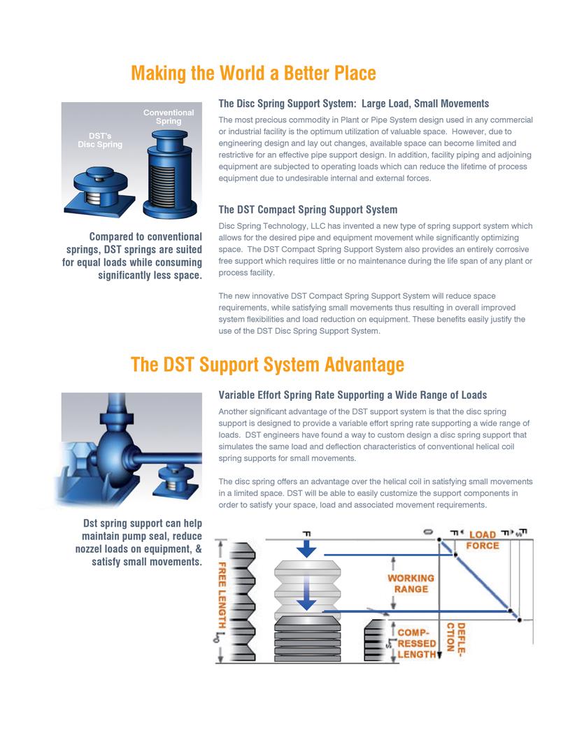
6 WHY USE DST SPRING SUPPORTS? AOUT DST DST has developed an innovative spring support system satisfying small movements in limited space. These features are not offered by conventional helical coil spring supports. Through careful manipulation of the conical spring washer s dimensional and mechanical characteristics, DST has developed a series of spring supports, which matches and exceeds the performance of helical coil spring supports in instances that require limited space. DST supports are based on the use of custom engineered conical (elleville) springs, which allows DST to offer a full range of patented spring supports that suite the need for large loads and small movements. This catalog provides conical spring support sizes that will support loads from 50 to 50,000 lbs and movements from 0 to 3/4". The working range for DST springs is between 45% to 85% maximum compression. However, for safety and durability, DST springs are designed for 100% compression without being overstressed. All the items shown in this catalog are Range Machines. They are made to be applied to a range of loads and movements. Custom made applications for a specific load and/or movements are offered upon request. DST Spring Supports have several added features that set them apart from helical coil spring supports. DST offers springs in carbon and stainless steel alloys. DST offers the entire spring support (spring and housing) made in corrosion resistant stainless steel or other suitable alloys making it ideal to combat aggressive corrosive environments like seawater, marine air, or corrosive chemicals. All DST supports are provided using guided load columns. DST recommends installation from ambient temperatures up to 225 degrees F. 1 Patent , All Rights Reserved.
7 ACKGROUND Why use spring supports? Spring supports are utilized to meet allowable loads required by equipment manufacturers on load sensitive equipment and vessel nozzles. Thermal pipe movements can range from thousands of an inch to several inches during a thermal cycle. Thermal movements of thousands of an inch can produce loads on equipment nozzles beyond their manufacturer s specified allowable loads. For these reasons, the need to satisfy thermal and gravitational loads on sensitive equipment in a piping system is just as important for movements measured in thousands of an inch as it is for large movements of several inches. In contrast, static supports are the principle means for supporting pipe systems but do not transfer loads off equipment nozzles. Rod hangers, base elbow or base line supports can cause more damage to equipment if they are not properly installed. An object lifted off its support is independent of the displacement. Particular to rotating equipment, the result of using a static support is often evident in seal damage, casing distortion and coupling misalignment. In conjunction, static supports can lead to over loading conditions and result in expensive equipment failure, down time and even injuries. The cost of down time is usually more expensive than the equipment itself. Simply stated, spring supports are insurance against down time and expensive repairs. Currently, helical coil springs are used to allow for thermal expansion within piping systems and to meet code requirements but there are many limitations related to their use. Design engineers are reluctant to use a helical coil spring support where movements are relatively small (i.e. 1/16"). Space limitations are often controlling factors near sensitive equipment. The helical coil spring support is too large an apparatus to typically install under piping or equipment in many instances. Corrosive, air-born materials including salt air in marine environments can attack carbon steel helical coil spring supports as well. In order to address these corrosion issues, spring manufacturers recommend the use of neoprene treated springs. It is also common practice to paint and galvanize carbon steel spring supports. However, there is no guarantee that the inner working parts are corrosion free while the spring support is assembled or remain corrosion free while it is in service. Patent , All Rights Reserved. 2
8 DST PRODUCT SOLUTIONS: Disc springs offer an advantage over helical coil springs in satisfying small displacements in limited space. y stacking conical springs and compressing them to a predetermined load, the DST Spring Support can effectively maintain support through an operating displacement in a minimum amount of space. y using conical springs, the height of a typical spring support can be reduced by 30% to 50% for displacements from 0 to 1/2. Further, due to a shorter profile, the DST Spring Support is suitable for placement under equipment such as pumps, turbines, compressor base plates, heat exchangers and equipment skids where a helical coil spring is impractical. To summarize the advantages of the DST Spring Support, the following features apply to its design: 1. The DST Spring Support satisfies small displacements of 0 to 3/4 within a minimum amount of space while effectively maintaining support of pipe or equipment within the piping system. 2. The entire DST Spring Support can be made with corrosion free materials by using stainless steel (conical) springs, which require no maintenance during the life of the support. This offers a safer and more reliable support for the lifetime of the system. 3. The DST Spring Support is designed to maintain the 25% variability requirements of MSS-SP58 ASME standard. 4. Leaks at pipe joints and equipment flange connections are reduced. 5. Excessive forces and moments on connected equipment such as pumps and turbines are minimized meeting nozzle load requirements set by the equipment s manufacturer. Excessive stresses on adjacent supporting and restraining elements are also minimized. 6. Extend equipment life by reducing costly equipment down time and maintenance. 7. Deflection and load characteristics can be changed in the spring support by stacking disc springs in series, parallel, or combinations of series and parallel. Various multiple stacking arrangements with different thicknesses can be made depending on the load requirements. This is ideal for unique situations where loads and movement requirements demand a stiffer or softer spring than is normally offered. 3 Patent , All Rights Reserved
9 Compared to Helical Springs: The geometry of the equipment nozzle on many different pieces of equipment demands the use of a compact spring support. The DST spring will support the same load through the same range of movement up to 3/4 as the helical coil spring support in a substantially smaller space. DST supports can be made for custom applications by changing the number of disc spring washers to meet the specified movement making it as short and inexpensive as possible. Helical coil spring supports do not offer this benefit particularly at smaller displacements as their lengths can not be cut to specific movements. This cost benefit can be considerably appreciable when stainless steel is concerned in conjunction with large loads. To illustrate the difference between helical coil springs and conical washers, the minimum height of a helical coil spring could be limited to the distance of one times the pitch of the helical coil plus one coil rod diameter. This height would be greater than the height of one conical washer. The helical coil spring would have less load carrying capability than a conical washer having less height. The helical coil spring force would be weak as its spring constant is dependent on its length or the amount it can compress. One can not obtain the high load settings required for small displacements simply by making the spring shorter. Its spring constant, by definition, is pounds per inch of compression, which means the spring constant for a helical coil spring is linear. Its working range could not encompass the 25% variability requirement of the MSS- SP58 standard practice; which is a requirement set by the ASME code for pressure piping. In contrast, the conical washer s load deflection characteristics are variable throughout its load range. ecause of its conical shape and design, the conical washer has a variable load deflection that is stiff in the pre-loaded position but acts similar to the helical coil spring s linear spring constant as it moves through its working range. oth deflection characteristics can be observed from the graphs presented in section 4. The following is one example of a situation that requires the need of a compact spring support; Plate and frame heat exchangers as described in the API 662 standard emphasizes the requirement of nozzle loading being kept to a minimum. Nozzles on load sensitive equipment are often located, by design, close to grade elevation and are obscured by obstructions such as platforms and other equipment. See Illustration on page 7. Typically on a plate and frame exchanger, 4 nozzles exist 2 inlet nozzles and 2 outlet nozzles. The 2 nozzles at the bottom are typically one pipe diameter (at the bottom of the pipe) in distance above the top of the exchanger s foundation. The allowable load for an eight-inch inlet nozzle or outlet nozzle of an API 662 standard service nozzle is 246 lbs. of force with a 911 lb-ft moment. Piping systems usually contain reducers connecting to the heat exchanger making the piping larger than the nozzle size of the exchanger. The weight alone of this piping and its fluid is almost always greater than the allowable load capacity that is specified by the code. A spring support is, obviously, required. The room for the spring support makes installation a challenge due to restricted space. A DST Spring is more suitable for direct installation in the limited space provided under the heat exchanger s lower nozzles. Patent , All Rights Reserved 4
10
11
12
13
14
15
16 SPRING SUPPORT SELECTION TALES Pages 16 and 17 include the Carbon Steel Selection Table while pages 18 and 19 include the Stainless Steel Selection Table. Describing the selection tables, the size is listed across the top row of each table. The movement for each size is shown in the columns at the left of the tables. (Note that there are five separate movement (or deflection) categories; each deflection category corresponds to the specific Figure Number: 1) Figure Supports that will satisfy movements up to (1/8 ), 2) Figure Supports that will satisfy movements up to (1/4 ), 3) Figure Supports that will satisfy movements up to (3/8 ), 4) Figure Supports that will satisfy movements up to (1/2 ), 5) Figure Supports that will satisfy movements up to (3/4 ). The corresponding operating and installed loads are listed from the top left to the lower right of each table within the columns for each size. The Effective Spring Rate Formula and Variability Rate Formula are provided below the spring selection table. Effective Spring Rate = Operating Load (lbs.) - Installed Load (lbs.) / Movement (in.) The % Variability = 100 (Operating Load - Installed Load) /Operating Load HOW TO SELECT A HANGER USING THE TALE The movement (displacement magnitude and direction up or down) from installed load (cold load) to operating load (hot load) must be known. The operating load (the actual weight of the piping) which the spring is to support must also be known. The Installed load (cold load), Figure Number, and size need to be selected. The conical washer spring rate is very close to linear, but it is not completely linear as indicated in the included graphs. The factors A,, C, D, E, & F are provided for each spring s size. The factors A,, & C are independent of the Figure Number. These are used to calculate loads for each Figure Number. The factors D, E, & F are based on Figure Number 250. These factors are used for calculating travel. The calculated travel must be divided by the Figure Number s Travel Factor. The Travel Factor for Figure Number 125 is 0.5. The Travel Factors for Figure Numbers 125, 250, 375, 500 & 750 are 0.5, 1, 1.5, 2 & 3 respectively. These factors, along with the equations provided, are used to calculate Y (the installed load) for any movement determining the support Figure Number and size. No interpolation is required. Find the operating load in the working range shown in the Spring Selection Table. If the operating load is outside the working range of the hanger selected, choose the operating load in the next larger size. 11 Patent , All Rights Reserved. Patent , All Rights Reserved.
17 To determine the installed load, read the spring scale, up or down, for the expected movement. The spring selection table is read in the opposite direction from the expected movement. The load arrived is the installed load. Selection is complete when the operating load and installed load are both within the working range of the selected size. The Spring Selection Table shows only loads within the working range. If a hanger is not available for the requirements within that working range, select a Figure Number with a wider range. The check for MSS SP-58 25% variability is then required. See complete numeric examples below. The Takeout, indicated in the Spring Support Figures & Types section drawings as Min. and Max., starts at the beginning of the spring s working range for 0 deflection. The amount of adjustment to bring the spring support to its installed Takeout will be demonstrated in the following examples. To simplify this process, an automatic selection program is available for selecting both stainless and carbon steel supports at Example 1: Carbon Steel Material Given: Operating load = 276 lbs. movement = up installed to operating Find the operating load using the selection table or graphs. 1. The first figure number that can envelope a movement = is a Figure Number 250 with a travel factor of The operating load of 276 Lbs. is first available in size 3CS. 3. The factors for that spring size 3CS are given as: A = , = , C = 23.68, D = 1.70 x 10⁻⁶, E = 9.24 x 10⁻⁴, F = 7.95 x Spring size 3CS is initially compressed to ( 0 ) = to begin its working range at (Y 0 ) = 211 lbs. initial load. 5. The operating load of Y = 276 lbs. load is found to be compressed to ( P ) = (using = (DY 2 + EY + F) with the factors D, E, & F for that Spring Size 3CS). 6. The movement from the installed load to the operating load is up. 7. The total movement ( I ) = (0.188 divided by a travel factor of 2.0) = The installed load for the total movement ( I ) = is found to be (Y I ) = lbs. (using Y = (A 2 + +C) with the factors A,, & C for that Spring Size 3CS.) 9. The Figure Number 250 can envelope that working range of lbs. installed load to 276 lbs. operating movement = up installed to operating. 10. The % Variability = 100 x (operating load - installed load) / operating load. The % Variability = 100 x (276 Lbs lbs.) / 276 lbs. = 17.54% < 25% Selection complete (MSS SP-58 satisfied). 11. Effective Spring Rate = (operating load - installed load) / movement Effective Spring Rate = (276 lbs lbs.) /.188 in. = lbs./in. 12. The adjustment for the installed Takeout is found to be = using (DY I 2 + EY I + F) + ( 0 ) with the factors D, E, F, & 0 for that spring size. 12 Patent , All Rights Reserved.
18 Example 2: Carbon Steel Material Given: Operating load = 400 lbs. movement = 0.22 up installed to operating Find the operating load using the selection table or graphs. 1. The first figure number that can envelope a movement =0.22 is a Figure Number 250 with a travel factor of The operating load of 400 lbs. is first available in size 4CS. 3. The factors for that Spring Size 4CS are given as: A , = , C = 30.78, D = 1.01x10⁻⁶, E = 7.14 x 10⁻⁴, F = 7.99 x Spring Size 4CS is initially compressed to ( 0 ) = to begin its working range at (Y 0 ) = 275 lbs. initial load. 5. The operating load of Y = 400 Lbs. Load is found to be compressed to ( P ) = (using = (DY 2 + EY + F) with the factors D, E, & F for that Spring Size 4CS). 6. The movement from the installed load to the operating load is 0.22 up. 7. The total movement ( I ) = (0.22 divided by a travel factor of 2.0) = The installed load for the total movement ( I ) =.5649 is found to be (Y I ) = lbs. (using Y = (A C) with the factors A,, & C for that Spring Size 4CS). 9. The Figure Number 250 can NOT envelope that working range of lbs. installed load to 400 lbs. operating movement = 0.22 up installed to operating. 10. Go to a next larger size spring as the operating load of 400 Lbs. is also available in size 5CS. As already stated, Figure Number 250 with a travel factor of 2.0 can envelope the movement. 11. The factors for that Spring Size 5CS are given as: A , = , C = 39.99, D = 5.88 x 10⁻⁷, E = 5.41 x 10⁻⁴, F = 7.86 x Spring Size 5CS is initially compressed to ( 0 ) = to begin its working range at (Y 0 ) = 357 lbs. initial load. 13. The operating load of Y = 400 lbs. load is found to be compressed to ( P ) = (using = (DY 2 + EY + F) with the factors D, E, & F for that Spring Size 4CS). 14. The movement from the installed load to the operating load is 0.22 up. 15. The total movement ( I ) = (0.22 divided by a travel factor of 2.0) = The installed load for the total movement ( I ) = is found to be (Y I ) = lbs. (using Y = (A C) with the factors A,, & C for that Spring Size 4CS). 13 Patent , All Rights Reserved.
19 17. The Figure Number 250 can envelope that working range of lbs. installed load to 400 lbs. operating movement = 0.22 up installed to operating. 18. The % Variability = 100 x (operating load - installed load) / operating load The % Variability = 100 x (400 lbs lbs.) / 400 lbs. = 25.75% > 25% Selection incomplete (MSS SP-58 not satisfied). 19. The next figure number that can envelope a movement = 0.22 is a Figure Number 375 with a travel factor of The operating load of 400 lbs. is first available in size 4CS. 21. The factors for that Spring Size 4CS are given as: A , = , C = 30.78, D = 1.01 x 10⁻⁶, E = 7.14 x 10⁻⁴, F = 7.99 x Spring Size 4CS is initially compressed to ( 0 ) = to begin its working range at (Y 0 ) = 275 Lbs. initial load. 23. The operating load of Y = 400 lbs. load is found to be compressed to ( P ) = (using = (DY 2 + EY + F) with the factors D, E, & F for that Spring Size 4CS). 24. The movement from the installed load to the operating load is 0.22 up. 25. The total movement ( I ) = (0.22 divided by a travel factor of 3.0) = The installed load for the total movement ( I ) = is found to be (Y I ) = lbs. (using Y = (A C) with the factors A,, & C for that Spring Size 4CS). 27. The Figure Number 375 that can envelope that working range of lbs., installed load to 400 lbs., operating movement = 0.22 up installed to operating. 28. The % Variability = 100 x (operating load - installed load) / operating load The % Variability = 100 x (400 lbs lbs.) / 400 lbs. = 11.73% < 25% Selection complete (MSS SP-58 satisfied). 29. Effective Spring Rate = (operating load - installed load) / movement Effective Spring Rate = (400 lbs lbs.) / 0.22 in. = lbs./in. 30. The adjustment for the installed Takeout is found to be = using (DY I 2 +EY I +F)+ ( 0 ) with the factors D, E, F, & 0 for that spring size. Patent , All Rights Reserved. 14 Patent , All Rights Reserved.
20 Example 3a: Carbon Steel Material Given: Operating load = 9763 lbs. movement = down installed to operating Find the operating load using the selection table or graphs. 1. The first figure number that can envelope a movement = is a Figure Number 250 with a travel factor of The operating load of 9763 Lbs. is first available in size 16CS. 3. The factors for that Spring Size 16CS are given as: 4. A = , = , C = , D = 1.56 x 10⁻⁹, E = 3.00 x 10⁻⁵, F = x Spring Size 16CS is initially compressed to ( 0 ) = to begin its working range at (Y 0 ) = 7596 lbs. initial load. 6. The operating load of Y = 9763 lbs. load is found to be compressed to ( P ) = (using = (DY 2 + EY + F) with the factors D, E, & F for that Spring Size 16CS). 7. The movement from the installed load to the operating load is down. 8. The total movement ( I ) = ( divided by a travel factor of 2.0.) = The installed load for the total movement ( I ) = is found to be (Y I ) = lbs. (using Y = (A C) with the factors A,, & C for that Spring Size 16CS). 10. The Figure Number 250 can envelope that working range of lbs. installed load to 9763 lbs. operating movement = down installed to operating. 11. The % Variability = 100 x (operating load - installed load) / operating load. The % Variability = 100 x (9763 lbs lbs.) / 9763 lbs. = 12.49% < 25% Selection complete (MSS SP-58 satisfied). 12. Effective Spring Rate = (operating load - installed load) / movement Effective Spring Rate = (9763 lbs lbs.) / in. = lbs./in. 13. The adjustment for the installed Takeout is found to be = using (DY I 2 + EY I + F)+ ( 0 ) with the factors D, E, F, & 0 for that spring size. 15 Patent , All Rights Reserved.
21 Example 3b: Carbon Steel Material The purpose of this example is to show how a special purpose support can be made out of a range support to save space. The requirements of this example are the same as Example 3a. 1. As shown in Example 3a, the first figure number that can envelope a movement = is a Figure Number 250 with a travel factor of 2.0. This is the starting point for a special purpose support. The special purpose support will be between a Figure Number 250 and a Figure Number 125. The Figure Number 250, size 16CS has 6 disc springs and the Figure Number 125, size 16CS has 3 disc springs. This is an example with 4 springs. The Figure Number 250 travel factor of 2.0 is adjusted by that ratio of 4 divided by 6 (=0.667). The Travel Factor of is now applied to Example 3a 2. Same as Example 3a. 3. Same as Example 3a 4. Same as Example 3a 5. Same as Example 3a 6. Same as Example 3a 7. Same as Example 3a 8. The total movement ( I ) = ( divided by a travel factor of ) = The installed load for the total movement ( I ) = is found to be (Y I ) = lbs. (using Y = (A C) with the factors A,, & C for that Spring Size 16CS). 10. The Figure Number 250 with a travel factor of can envelope that working range of lbs. installed load to 9763 lbs. operating movement = down installed to operating. 11. The % Variability = 100 x (operating load - installed load) / operating load The % Variability = 100 x (9763 lbs lbs.) / 9763 lbs. = 18.55% < 25% Selection complete (MSS SP-58 satisfied). 12. Effective Spring Rate = (operating load - installed load) / movement Effective Spring Rate = (9763 lbs lbs.) / in. = lbs./in. 13. Note that this spring support is shorter than the support with 6 springs as described in Example 3a above for Figure Number 250 size 16CS. (Any movement can be accommodated upon special request.) Patent , All Rights Reserved. 16
22 Working Range Deflection (inch) CARON STEEL SPRING SIZES / LOADS (lbs) FIG 750 Travel Factor=6 FIG 500 Travel Factor=4 FIG 375 Travel Factor=3 FIG 250 Travel Factor=2 FIG 125 Travel Factor=1 1CS 2CS 3CS 4CS 5CS 6CS 7CS 8CS 9CS /64 1/32 3/128 1/64 1/ /32 1/16 3/64 1/32 1/ /16 1/8 3/32 1/16 1/ /32 3/16 9/64 3/32 3/ /8 1/4 3/16 1/8 1/ /32 5/16 15/64 5/32 5/ , ,030 9/16 3/8 9/32 3/16 3/ , ,065 21/32 7/16 21/64 7/32 7/ , ,099 3/4 1/2 3/8 1/4 1/ , ,132 27/32 9/16 27/64 9/32 9/ , ,166 15/16 5/8 15/32 5/16 5/ , , /32 11/16 33/64 11/32 11/ , , /8 3/4 9/16 3/8 3/ , , /32 13/16 39/64 13/32 13/ , , /16 7/8 21/32 7/16 7/ , , /32 15/16 45/64 15/32 15/ ,001 1, ,011 1, /2 1 3/4 1/2 1/ ,022 1, , /32 1 1/16 51/64 17/32 17/ /16 1 1/8 27/32 9/16 9/ /32 1 3/16 57/64 19/32 19/ /8 1 1/4 15/16 5/8 5/ /32 1 5/16 63/64 21/32 21/ /16 1 3/8 1 1/32 11/16 11/ /32 1 7/16 1 5/64 23/32 23/ /4 1 1/2 1 1/8 3/4 3/ /64 1/32 3/128 1/64 1/128 GRADUATION FOR EACH ROW SHOWN AOVE VARIAILITY = AS. VALUE(OPERATING LOAD - INSTALLED LOAD)/OPERATING LOAD Y I = ( 2 *A+*+C) Load Lbs. INITIAL MOVEMENT P = (Y 2 *D+Y*E+F) Mvmt. Inches 17 Constants Constants A C O D 7.49E E E E E E E E E-07 E 1.94E E E E E E E E E-04 F 7.92E E E E E E E E E-03
23 CARON STEEL SPRING SIZES / LOADS (lbs) 10CS 11CS 12CS 13CS 14CS 15CS 16CS 17CS 18CS 19CS 20CS 21CS 22CS Preload 1,094 1,432 1,882 2,477 3,260 4,332 5,762 7,596 10,099 13,214 17,091 22,636 30,990 1,118 1,463 1,919 2,523 3,330 4,408 5,891 7,737 10,266 13,505 17,425 23,023 31,437 1,143 1,493 1,957 2,568 3,400 4,484 6,018 7,878 10,432 13,793 17,758 23,409 31,881 1,168 1,523 1,993 2,614 3,470 4,560 6,145 8,018 10,597 14,080 18,089 23,793 32,324 1,192 1,553 2,030 2,659 3,539 4,635 6,271 8,158 10,761 14,365 18,418 24,174 32,765 1,216 1,583 2,067 2,704 3,608 4,709 6,395 8,296 10,924 14,648 18,745 24,554 33,204 1,240 1,612 2,103 2,749 3,676 4,784 6,519 8,434 11,086 14,929 19,069 24,932 33,641 1,264 1,641 2,139 2,793 3,744 4,858 6,642 8,571 11,248 15,208 19,392 25,307 34,076 1,288 1,671 2,175 2,837 3,811 4,931 6,765 8,707 11,409 15,485 19,713 25,681 34,509 1,311 1,699 2,211 2,881 3,878 5,004 6,886 8,842 11,569 15,760 20,031 26,052 34,940 1,335 1,728 2,246 2,925 3,945 5,077 7,006 8,976 11,728 16,033 20,348 26,422 35,369 1,358 1,757 2,281 2,968 4,011 5,149 7,126 9,110 11,886 16,304 20,663 26,789 35,796 1,381 1,785 2,316 3,011 4,076 5,221 7,245 9,243 12,043 16,573 20,975 27,154 36,221 1,404 1,813 2,351 3,054 4,141 5,292 7,363 9,375 12,200 16,840 21,286 27,518 36,644 1,426 1,841 2,385 3,097 4,205 5,363 7,480 9,506 12,355 17,106 21,595 27,879 37,065 1,449 1,869 2,419 3,139 4,269 5,434 7,596 9,636 12,510 17,369 21,901 28,238 37,484 1,471 1,896 2,453 3,181 4,333 5,504 7,711 9,766 12,664 17,630 22,206 28,595 37,901 1,493 1,923 2,487 3,223 4,396 5,574 7,825 9,895 12,817 17,889 22,509 28,951 38,316 1,515 1,950 2,521 3,264 4,459 5,643 7,939 10,023 12,970 18,147 22,809 29,304 38,730 1,537 1,977 2,554 3,306 4,521 5,712 8,051 10,150 13,121 18,402 23,108 29,655 39,141 1,558 2,004 2,587 3,347 4,583 5,780 8,163 10,276 13,272 18,655 23,404 30,004 39,550 1,580 2,031 2,620 3,387 4,644 5,848 8,274 10,401 13,421 18,907 23,699 30,351 39,957 1,601 2,057 2,653 3,428 4,705 5,916 8,384 10,526 13,570 19,156 23,991 30,696 40,363 1,622 2,083 2,685 3,468 4,765 5,983 8,493 10,650 13,718 19,404 24,282 31,039 40,766 1,643 2,109 2,717 3,508 4,825 6,050 8,601 10,773 13,866 19,649 24,570 31,380 41,167 1,664 2,135 2,749 3,548 4,884 6,117 8,708 10,895 14,012 19,893 24,857 31,719 41,567 1,684 2,160 2,781 3,587 4,943 6,183 8,814 11,017 14,158 20,135 25,141 32,055 41,964 1,705 2,185 2,812 3,627 5,001 6,248 8,920 11,137 14,302 20,374 25,424 32,390 42,360 1,725 2,211 2,843 3,665 5,059 6,313 9,025 11,257 14,446 20,612 25,704 32,723 42,753 1,745 2,235 2,874 3,704 5,117 6,378 9,128 11,376 14,589 20,848 25,983 33,054 43,145 1,765 2,260 2,905 3,742 5,174 6,443 9,231 11,494 14,731 21,082 26,259 33,382 43,534 1,784 2,285 2,936 3,781 5,230 6,507 9,333 11,612 14,873 21,313 26,534 33,709 43,922 1,804 2,309 2,966 3,818 5,286 6,570 9,434 11,728 15,013 21,543 26,806 34,034 44, ,333 2,996 3, ,633 9,535 11,844 15,153 21,771 27,076 34,356 44, ,026 3, ,696 9,634 11,959 15,292 21,997 27,345 34,677 45, ,056 3, ,758 9,733 12,073 15,429 22,221 27,611 34,995 45, , ,820 9,830 12,187 15,567 22,443 27,875 35,312 45, , ,882 9,927 12,299 15,703 22, ,626 46, ,943 10, ,838 22, ,939 46, ,003 10, ,973 23, , ,064 10, ,107 23, , , ,240 23, , , ,372 23, , , , , , , , , , , , ,208 SPRING WORKING RANGE EFFECTIVE SPRING RATE = ASOLUTE VALUE (OPERATING LOAD-INSTALLED LOAD) / MOVEMENT E E E E E E E E E E E E E E E E E E E E E E E E E E E E E E E E E E E-02 18
24 Working Range Deflection (inch) STAINLESS STEEL SPRING SIZES / LOADS (lbs) FIG 750 Travel Factor=6 FIG 500 Travel Factor=4 FIG 375 Travel Factor=3 FIG 250 Travel Factor=2 FIG 125 Travel Factor=1 1SS 2SS 3SS 4SS 5SS 6SS 7SS 8SS 9SS 10SS /64 1/32 3/128 1/64 1/ /32 1/16 3/64 1/32 1/ /16 1/8 3/32 1/16 1/ /32 3/16 9/64 3/32 3/ /8 1/4 3/16 1/8 1/ /32 5/16 15/64 5/32 5/ /16 3/8 9/32 3/16 3/ /32 7/16 21/64 7/32 7/ /4 1/2 3/8 1/4 1/ /32 9/16 27/64 9/32 9/ /16 5/8 15/32 5/16 5/ /32 11/16 33/64 11/32 11/ /8 3/4 9/16 3/8 3/ /32 13/16 39/64 13/32 13/ /16 7/8 21/32 7/16 7/ /32 15/16 45/64 15/32 15/ /2 1 3/4 1/2 1/ /32 1 1/16 51/64 17/32 17/ /16 1 1/8 27/32 9/16 9/ /32 1 3/16 57/64 19/32 19/ /8 1 1/4 15/16 5/8 5/ /32 1 5/16 63/64 21/32 21/ /16 1 3/8 1 1/32 11/16 11/ /32 1 7/16 1 5/64 23/32 23/ /4 1 1/2 1 1/8 3/4 3/ /64 1/32 3/128 1/64 1/128 GRADUATION FOR EACH ROW SHOWN AOVE VARIAILITY = AS. VALUE(OPERATING LOAD - INSTALLED LOAD)/OPERATING LOAD Y I = ( 2 *A+*+C) Load Lbs. INITIAL MOVEMENT P = (Y 2 *D+Y*E+F) Mvmt. Inches 19 Constants Constants A C O D 1.50E E E E E E E E E E-07 E 1.83E E E E E E E E E E-04 F 2.63E E E E E E E E E E-03
25 STAINLESS STEEL SPRING SIZES / LOADS (lbs) 11SS 12SS 13SS 14SS 15SS 16SS 17SS 18SS 19SS 20SS 21SS 22SS 23SS Preload SPRING WORKING RANGE EFFECTIVE SPRING RATE = ASOLUTE VALUE (OPERATING LOAD - INSTALLED LOAD) / MOVEMENT E E E E E E E E E E E E E E E E E E E E E E E E E E E E E E E E E E E E E E E-02 20
26 SPRING SUPPORT SELCTION GRAPHS As an illustrative tool, we have also provided a series of graphs to show the load vs. deflection (movement) range per support. The graphs are separated into two materials: carbon steel and stainless steel. The spring sizes are separated into five figure numbers (125, 250, 375, 500 and 750) similar to the spring support selection tables. The working range is indicated by the blue region in each graph. In order to simplify the number of graphs, we have only supplied the Figure 125 movement class of each material. Since the load range (x-axis) for each support figure is equal for the five figure classes, all that is needed to locate the size equal to the support chosen in the selection tables is to multiply the movement (y-axis) by the scalar quantity of the movement (figure) that is desired. For example, if the known load range is between 600 lbs and 725 lbs and the desired movement is 3/8, a Figure 375 support is needed to produce a movement of The movement for this load range is read on the y-axis as a movement between 0.34 and To find the movement with the same load range for a Figure 375 carbon steel support, multiply the 0.34 and 0.45 by 3 yielding 1.02 and 1.35, respectfully (and a displacement of 0.33 ). To find the movement of the same load range for a 1/2 movement (or a Figure 500 carbon steel support), multiply the 0.34 and 0.45 by 4 yielding 1.36 and 1.80, respectfully (or a displacement of 0.44 ). 21 Patent , All Rights Reserved.
27 CARON STEEL Carbon Steel (Figure 125 CS) Carbon Steel Sizes: 1 CS 2 CS 3CS 4 CS 5 CS 0.70 Movement (Inch) Pre-Loaded Range Spring Working Range Mid Range Load (Lbs) Carbon Steel (Figure 125 CS) 0.70 Carbon Steel Sizes: 6 CS 7 CS 8 CS Movement (Inch) Spring Working Range Mid Range Load (Lbs) 22
28 CARON STEEL Carbon Steel (Figure 125 CS) 0.65 Carbon Steel Sizes: 9 CS 10 CS Movement (Inch) Spring Working Range Mid Range Load (Lbs) Carbon Steel (Figure 125 CS) Movement (Inch) Spring Working Range 870 Carbon Steel Sizes: 11 CS 12 CS Mid Range Load (Lbs) 23
29 CARON STEEL Movement (Inch) Spring Working Range Carbon Steel (Figure 125 CS) CS 14 CS 15 CS 3934 Carbon Steel Sizes: Mid Range Load (Lbs) 7963 Movement (Inch) Spring Working Range Carbon Steel (Figure 125 CS) Carbon Steel Sizes: 16 CS 17 CS 18 CS Load (Lbs) Mid Range
30 CARON STEEL Carbon Steel (Figure 125 CS) Movement (Inch) Carbon Steel Sizes: 19 CS 20 CS Spring Working Range Mid Range Load (Lbs) Movement (Inch) Carbon Steel (Figure 125 CS) Carbon Steel Sizes: 21 CS 22 CS Spring Working Range Load (Lbs) Mid Range
31 STAINLESS STEEL Stainless Steel (Figure125 SS) Movement (Inch) Stainless Steel Sizes: 1SS 2SS 3SS 4SS Spring Working Range: % to 85% Compression Mid Range Load (Lbs) Stainless Steel (Figure 125 SS) Movement (Inch) Stainless Steel Sizes: 5SS 6SS 7SS 8SS Spring Working Range: % to 85% Compression Mid Range Load (Lbs) 26
32 STAINLESS STEEL Stainless Steel (Figure 125 SS) Movement (Inch) Spring Working Range: % to 85% Compression Mid Range Stainless Steel Sizes: 9SS 10SS 11SS 12SS Load (Lbs) Movement (Inch) Stainless Steel (Figure 125 SS) Spring Working Range: % to 85% Compression Mid Range Stainless Steel Sizes: 13SS 14SS 15SS Load (Lbs) 27
33 STAINLESS STEEL Movement (Inch) Spring Working Range: 45% to 85% Compression Stainless Steel (FIgure 125 SS) 16SS 17SS 18SS 19SS Stainless Steel Sizes: Load (Lbs) Mid Range Stainless Steel (Figure 125 SS) Stainless Steel Sizes: Movement (Inch) Spring Working Range: % to 85% Compression Mid Range SS 21SS Load (Lbs) 28
34 STAINLESS STEEL Movement (Inch) Spring Working Range: 45% to 85% Compression Stainless Steel (TYPE 125 SS) Stainless Steel Sizes: 22SS Mid Range Load (Lbs) 23SS 29
35 DST CARON STEEL SPRING SUPPORT TYPES, FIGURES AND SIZES The overall dimensions of each figure type are provided in this section. DST Carbon Steel Spring Supports are divided into five displacement categories: 1) Figure Supports that will satisfy movements up to (1/8 ), 2) Figure Supports that will satisfy movements up to (1/4 ), 3) Figure Supports that will satisfy movements up to (3/8 ), 4) Figure Supports that will satisfy movements up to (1/2 ), 5) Figure Supports that will satisfy movements up to (3/4 ). Patent , Patent , All Rights All Rights Reserved. 30
36 Item SIZE C Cover Plate D ase Plate Square E ottom olt Circle ase Plate olt ase Plate Thk. Min Max Load Col. Load Load Thk. Wgt lbs. (est.) 1CS 2 2 3/8 4 3/8 4 3/8 3 1/2 3/8 3/16 3 1/2 3 7/ /16 4 2CS 2 2 3/8 4 3/8 4 3/8 3 1/2 3/8 3/16 3 9/ / /8 3/16 4 3CS 2 2 7/8 4 7/8 4 7/8 4 3/8 3/16 3 9/ / /8 3/16 5 4CS 2 2 3/8 4 3/8 4 3/8 3 1/2 3/8 3/16 3 9/ / /8 3/16 4 5CS 2 4 1/2 6 1/2 6 1/2 5 5/8 3/8 3/16 3 9/ / /8 3/ CS 2 1/8 2 7/8 4 7/8 4 7/8 4 3/8 1/4 3 3/4 4 3/ /8 3/16 6 7CS 2 5/16 4 1/2 6 1/2 6 1/2 5 5/8 3/8 3/ / /8 1/4 12 8CS 2 9/16 6 5/8 8 5/8 8 5/8 7 3/4 1/2 3/8 4 3/8 4 15/16 3 1/2 3 7/8 3/8 22 9CS 2 5/8 6 5/8 8 5/8 8 5/8 7 3/4 1/2 1/2 4 3/8 4 15/16 2 7/8 3 7/8 1/ CS 2 11/16 8 5/8 10 3/4 10 3/4 9 7/8 1/2 1/2 4 9/16 5 3/16 4 1/2 5 3/4 3/ CS 2 7/8 8 5/ /2 5/8 4 13/16 5 7/16 4 1/2 6 3/8 3/ CS 3 8 5/ /4 5/ /8 4 1/2 6 3/8 3/ CS 3 7/16 8 5/ /2 3/4 3/4 5 5/8 6 3/8 4 1/2 6 3/8 1/ CS 3 7/8 8 5/ /2 3/4 3/4 6 1/8 6 13/16 4 1/2 8 3/8 1/ CS 4 3/ /4 14 3/8 14 3/8 12 7/8 3/4 3/4 6 9/16 7 1/2 4 1/2 8 3/8 5/ CS 3 15/ /4 14 1/2 14 1/2 13 3/4 3/4 6 5/ /16 8 3/8 5/ CS 4 3/ /4 17 3/8 17 3/8 15 7/16 1 3/4 6 7/8 7 3/4 5 9/16 8 3/8 3/ CS 5 1/ /8 9 1/8 5 9/16 8 3/ CS 5 1/ /16 8 3/4 6 5/8 12 1/ CS 5 1/ /16 8 5/8 12 1/2 1 1/ CS 6 5/ /4 11 1/4 8 5/8 12 1/2 1 1/ CS 7 1/ / / /4 12 1/2 1 5/8 787
37 Item SIZE C D ottom Square E ottom olt Circle ase Plate olt ottom Thk. Min Max Load Col. Load Load Thk. Wgt lbs. (est.) 1CS 2 2 3/8 4 3/8 4 3/8 3 1/2 3/8 3/16 3 1/2 3 11/ /16 4 2CS 2 2 3/8 4 3/8 4 3/8 3 1/2 3/8 3/16 3 9/16 3 3/ /8 3/16 4 3CS 2 2 7/8 4 7/8 4 7/8 4 3/8 3/16 3 9/16 3 3/ /8 3/16 5 4CS 2 2 3/8 4 3/8 4 3/8 3 1/2 3/8 3/16 3 9/16 3 3/ /8 3/16 4 5CS 2 4 1/2 6 1/2 6 1/2 5 5/8 3/8 3/16 3 9/16 3 3/ /8 3/ CS 2 1/8 2 7/8 4 7/8 4 7/8 4 3/8 1/4 3 3/ /8 3/16 6 7CS 2 5/16 4 1/2 6 1/2 6 1/2 5 5/8 3/8 3/ / /8 1/4 12 8CS 2 9/16 6 5/8 8 5/8 8 5/8 7 3/4 1/2 3/8 4 3/8 4 3/4 3 1/2 3 7/8 3/8 22 9CS 2 5/8 6 5/8 8 5/8 8 5/8 7 3/4 1/2 1/2 4 3/8 4 3/4 2 7/8 3 7/8 1/ CS 2 11/16 8 5/8 10 3/4 10 3/4 9 7/8 1/2 1/2 4 1/2 4 7/8 4 1/2 5 3/4 3/ CS 2 7/8 8 5/ /2 5/8 4 3/4 5 1/8 4 1/2 6 3/8 3/ CS 3 8 5/ /4 5/ /8 4 1/2 6 3/8 3/ CS 3 7/16 8 5/ /2 3/4 3/4 5 5/8 6 1/8 4 1/2 6 3/8 1/ CS 3 7/8 8 5/ /2 3/4 3/4 6 5/16 7 1/16 4 1/2 8 3/8 1/ CS 4 3/ /4 14 3/8 14 3/8 12 7/8 3/4 3/4 6 5/8 7 3/8 4 1/2 8 3/8 5/ CS 3 15/ /4 14 1/2 14 1/2 13 3/4 3/4 6 7/16 7 3/16 5 9/16 8 3/8 5/ CS 4 3/ /4 17 3/8 17 3/8 15 7/16 1 3/4 7 1/ /16 5 9/16 8 3/8 3/ CS 5 1/ /16 9 7/16 5 9/16 8 3/ CS 5 1/ / /16 6 5/8 12 1/ CS 5 1/ /8 11 1/8 8 5/8 12 1/2 1 1/ CS 6 5/ /8 12 7/8 8 5/8 12 1/2 1 1/ CS 7 1/ / / /4 12 1/2 1 5/8 793
38 Ite m SIZE Rod Dia m. A Le ngth Dia m. C Diam. E Min Le ngth Max W gt lbs. (e st.) 1CS 1/ /8 4 3/8 3 1/2 3 11/16 4 2CS 1/ /8 4 3/8 3 9/16 3 3/4 4 3CS 1/ /8 4 7/8 3 9/16 3 3/4 5 4CS 1/ /8 4 3/8 3 9/16 3 3/4 4 5CS 1/ /2 6 1/2 3 9/16 3 3/4 10 6CS 1/2 2 1/16 2 7/8 4 7/8 3 11/ /16 5 7CS 1/2 2 3/16 4 1/2 6 1/2 3 7/8 4 1/8 11 8CS 1/2 2 5/8 6 5/8 8 5/8 4 1/2 4 7/8 22 9CS 3/4 2 9/16 6 5/8 8 5/8 4 1/2 4 7/ CS 3/4 2 11/16 8 5/8 10 3/4 4 5/ CS 3/4 2 7/8 8 5/ /8 5 1/ CS / /4 5 5/ CS 1 3 9/16 8 5/ / CS 1 1/4 4 1/4 8 5/ /16 7 9/ CS 1 1/2 4 11/ /4 14 3/8 7 5/8 8 3/ CS 1 1/2 4 11/ /4 14 1/2 7 11/16 8 7/ CS 1 3/4 5 3/8 12 3/4 17 3/8 8 11/16 9 7/ CS 2 6 3/ / / CS 2 1/4 7 1/ / / CS 2 3/4 7 1/ /8 12 7/ CS 2 3/4 8 15/ /8 15 1/ CS / / /
39 Item SIZE Rod A D E Min Max Lug Thk. T Lug radius R Pin height H Lug Hole Diameter F Wgt lbs. (est.) 1CS 1/ /8 4 3/8 3 1/2 3 11/16 1/4 1 1/4 1 1/2 11/16 4 2CS 1/ /8 4 3/8 3 9/16 3 3/4 1/4 1 1/4 1 1/2 11/16 4 3CS 1/ /8 4 7/8 3 9/16 3 3/4 1/4 1 1/4 1 1/2 11/16 5 4CS 1/ /8 4 3/8 3 9/16 3 3/4 1/4 1 1/4 1 1/2 11/16 4 5CS 1/ /2 6 1/2 3 9/16 3 3/4 1/4 1 1/4 1 1/2 11/ CS 1/2 2 1/16 2 7/8 4 7/8 3 11/ /16 1/4 1 1/4 1 1/2 11/16 5 7CS 1/2 2 3/16 4 1/2 6 1/2 3 7/8 4 1/8 1/4 1 1/4 1 1/2 13/ CS 1/2 2 5/8 6 5/8 8 5/8 4 1/2 4 7/8 1/4 1 1/4 1 1/2 13/ CS 3/4 2 9/16 6 5/8 8 5/8 4 1/2 4 7/8 3/8 1 1/4 1 1/2 15/ CS 3/4 2 11/16 8 5/8 10 3/4 4 5/8 5 3/8 1 1/4 1 1/2 15/ CS 3/4 2 7/8 8 5/ /8 5 1/2 3/8 1 1/4 1 1/2 15/ CS / /4 5 5/8 1/2 1 1/ / CS 1 3 9/16 8 5/ /2 1/2 1 1/ / CS 1 1/4 4 1/4 8 5/ /16 7 9/16 5/ / CS 1 1/2 4 11/ /4 14 3/8 7 5/8 8 3/8 5/ / CS 1 1/2 4 11/ /4 14 1/2 7 11/16 8 7/16 3/4 2 1/ / CS 1 3/4 5 3/8 12 3/4 17 3/8 8 11/16 9 7/16 3/4 2 1/ CS 2 6 3/ / /16 3/ / CS 2 1/4 7 1/ / /16 3/ /2 2 5/ CS 2 3/4 7 1/ /8 12 7/ /2 3 1/ CS 2 3/4 8 15/ /8 15 1/ /2 3 1/ CS / / / /8 1147
40 Item SIZE Rod A C D Min Max Lug Thk. T clevis opening S Lug radius R Pin height H Lug Hole Diameter F Wgt lbs. (est.) 1CS 1/ /8 4 3/8 3 1/2 3 11/16 1/4 7/8 1 1/4 1 1/2 11/16 4 2CS 1/ /8 4 3/8 3 9/16 3 3/4 1/4 7/8 1 1/4 1 1/2 11/16 4 3CS 1/ /8 4 7/8 3 9/16 3 3/4 1/4 7/8 1 1/4 1 1/2 11/16 5 4CS 1/ /8 4 3/8 3 9/16 3 3/4 1/4 7/8 1 1/4 1 1/2 11/16 4 5CS 1/ /2 6 1/2 3 9/16 3 3/4 1/4 7/8 1 1/4 1 1/2 11/ CS 1/2 2 1/16 2 7/8 4 7/8 3 11/ /16 1/4 1 1/16 1 1/4 1 1/2 11/16 5 7CS 1/2 2 3/16 4 1/2 6 1/2 3 7/8 4 1/8 1/4 1 1/16 1 1/4 1 1/2 13/ CS 1/2 2 5/8 6 5/8 8 5/8 4 1/2 4 7/8 1/4 1 1/16 1 1/4 1 1/2 13/ CS 3/4 2 9/16 6 5/8 8 5/8 4 1/2 4 7/8 3/8 1 1/4 1 1/4 1 1/2 15/ CS 3/4 2 11/16 8 5/8 10 3/4 4 5/8 5 3/8 1 1/4 1 1/4 1 1/2 15/ CS 3/4 2 7/8 8 5/ /8 5 1/2 3/8 1 1/4 1 1/4 1 1/2 15/ CS / /4 5 5/8 1/2 1 5/8 1 1/ / CS 1 3 9/16 8 5/ /2 1/2 1 5/8 1 1/ / CS 1 1/4 4 1/4 8 5/ /16 7 9/16 5/ / CS 1 1/2 4 11/ /4 14 3/8 7 5/8 8 3/8 5/ / CS 1 1/2 4 11/ /4 14 1/2 7 11/16 8 7/16 3/4 2 3/8 2 1/ / CS 1 3/4 5 3/8 12 3/4 17 3/8 8 11/16 9 7/16 3/4 2 5/8 2 1/ CS 2 6 3/ / /16 3/4 2 7/ / CS 2 1/4 7 1/ / /16 3/4 3 1/ /2 2 5/ CS 2 3/4 7 1/ /8 12 7/ / /2 3 1/ CS 2 3/4 8 15/ /8 15 1/ / /2 3 1/ CS / / / / /8 1147
41 Item SIZE C Cover Plate D ase Plate Square E ottom olt Circle ase Plate olt ase Plate Thk. Min Max Load Col. Load Load Thk. Wgt lbs. (est.) 1CS 3 3/16 2 3/8 4 3/8 4 3/8 3 1/2 3/8 3/16 5 1/16 5 7/ /16 5 2CS 3 1/4 2 3/8 4 3/8 4 3/8 3 1/2 3/8 3/16 5 3/16 5 9/ /8 3/16 5 3CS 3 2 7/8 4 7/8 4 7/8 4 3/8 3/16 5 3/16 5 9/ /8 3/16 7 4CS 3 3/16 2 3/8 4 3/8 4 3/8 3 1/2 3/8 3/16 5 1/8 5 1/ /8 3/16 6 5CS 3 3/16 4 1/2 6 1/2 6 1/2 5 5/8 3/8 3/16 5 1/8 5 1/ /8 3/ CS 3 3/8 2 7/8 4 7/8 4 7/8 4 3/8 1/4 5 5/16 5 3/ /8 3/16 7 7CS 3 5/8 4 1/2 6 1/2 6 1/2 5 5/8 3/8 3/8 5 5/8 6 1/ /8 1/4 16 8CS 3 13/16 6 5/8 8 5/8 8 5/8 7 3/4 1/2 3/ /16 3 1/2 3 7/8 3/8 28 9CS 3 13/16 6 5/8 8 5/8 8 5/8 7 3/4 1/2 1/2 5 15/16 6 1/2 2 7/8 3 7/8 1/ CS 3 7/8 8 5/8 10 3/4 10 3/4 9 7/8 1/2 1/2 6 1/8 6 3/4 4 1/2 5 3/4 3/ CS 4 3/16 8 5/ /2 5/8 6 7/16 7 1/16 4 1/2 6 3/8 3/ CS 4 3/8 8 5/ /4 5/8 6 3/4 7 3/8 4 1/2 6 3/8 3/ CS 4 15/16 8 5/ /2 3/4 3/4 7 1/2 8 1/4 4 1/2 6 3/8 1/ CS 5 1/8 8 5/ /2 3/4 3/4 7 11/ /16 4 1/2 8 3/8 1/ CS 5 11/ /4 14 3/8 14 3/8 12 7/8 3/4 3/4 8 9/ /16 4 1/2 8 3/8 5/ CS 5 3/ /4 14 1/2 14 1/2 13 3/4 3/4 7 7/8 9 1/8 5 9/16 8 3/8 5/ CS 5 11/ /4 17 3/8 17 3/8 15 7/16 1 3/4 8 11/ /16 5 9/16 8 3/8 3/ CS 6 13/ / /16 5 9/16 8 3/ CS 6 7/ /8 11 1/4 6 5/8 12 1/ CS 6 7/ / /8 8 5/8 12 1/2 1 1/ CS 7 15/ / /8 8 5/8 12 1/2 1 1/ CS / / /4 12 1/2 1 5/8 915
42 Item SIZE C D ottom Square E ottom olt Circle ase Plate olt ottom Thk. Min Max Load Col. Load Load Thk. Wgt lbs. (est.) 1CS 3 3/16 2 3/8 4 3/8 4 3/8 3 1/2 3/8 3/16 5 1/16 5 1/ /16 5 2CS 3 1/4 2 3/8 4 3/8 4 3/8 3 1/2 3/8 3/16 5 3/16 5 3/ /8 3/16 5 3CS 3 2 7/8 4 7/8 4 7/8 4 3/8 3/16 5 3/16 5 3/ /8 3/16 7 4CS 3 3/16 2 3/8 4 3/8 4 3/8 3 1/2 3/8 3/16 5 1/8 5 5/ /8 3/16 6 5CS 3 3/16 4 1/2 6 1/2 6 1/2 5 5/8 3/8 3/16 5 1/8 5 5/ /8 3/ CS 3 3/8 2 7/8 4 7/8 4 7/8 4 3/8 1/4 5 5/16 5 9/ /8 3/16 7 7CS 3 5/8 4 1/2 6 1/2 6 1/2 5 5/8 3/8 3/8 5 5/8 5 7/ /8 1/4 16 8CS 3 13/16 6 5/8 8 5/8 8 5/8 7 3/4 1/2 3/ /8 3 1/2 3 7/8 3/8 28 9CS 3 13/16 6 5/8 8 5/8 8 5/8 7 3/4 1/2 1/2 5 15/16 6 5/16 2 7/8 3 7/8 1/ CS 3 7/8 8 5/8 10 3/4 10 3/4 9 7/8 1/2 1/2 6 1/16 6 7/16 4 1/2 5 3/4 3/ CS 4 3/16 8 5/ /2 5/8 6 3/8 6 3/4 4 1/2 6 3/8 3/ CS 4 3/8 8 5/ /4 5/8 6 3/4 7 1/8 4 1/2 6 3/8 3/ CS 4 15/16 8 5/ /2 3/4 3/4 7 1/ /2 6 3/8 1/ CS 5 1/8 8 5/ /2 3/4 3/4 7 11/16 8 7/16 4 1/2 8 3/8 1/ CS 5 11/ /4 14 3/8 14 3/8 12 7/8 3/4 3/4 8 9/16 9 5/16 4 1/2 8 3/8 5/ CS 5 3/ /4 14 1/2 14 1/2 13 3/4 3/4 7 3/4 8 1/2 5 9/16 8 3/8 5/ CS 5 11/ /4 17 3/8 17 3/8 15 7/16 1 3/4 8 11/16 9 7/16 5 9/16 8 3/8 3/ CS 6 13/ / /16 5 9/16 8 3/ CS 6 7/ /8 10 7/8 6 5/8 12 1/ CS 6 7/ / /16 8 5/8 12 1/2 1 1/ CS 7 15/ / /16 8 5/8 12 1/2 1 1/ CS / / /4 12 1/2 1 5/8 912
43 Item SIZE Rod A C E Min Max Wgt lbs. (est.) 1CS 1/2 3 3/16 2 3/8 4 3/8 5 1/16 5 1/4 5 2CS 1/2 3 1/4 2 3/8 4 3/8 5 3/16 5 3/8 5 3CS 1/ /8 4 7/8 5 3/16 5 3/8 7 4CS 1/2 3 3/16 2 3/8 4 3/8 5 1/8 5 5/16 6 5CS 1/2 3 3/16 4 1/2 6 1/2 5 1/8 5 5/ CS 1/2 3 5/16 2 7/8 4 7/8 5 1/4 5 1/2 7 7CS 1/2 3 1/2 4 1/2 6 1/2 5 1/2 5 3/4 14 8CS 1/2 3 7/8 6 5/8 8 5/8 6 1/8 6 1/2 28 9CS 3/4 3 3/4 6 5/8 8 5/8 6 1/16 6 7/ CS 3/4 3 7/8 8 5/8 10 3/4 6 3/16 6 9/ CS 3/4 4 3/16 8 5/ /4 7 1/ CS 1 4 3/8 8 5/ / CS 1 5 1/16 8 5/ /8 8 3/ CS 1 1/4 5 1/4 8 5/ / / CS 1 1/2 6 3/ /4 14 3/8 9 9/ / CS 1 1/2 5 11/ /4 14 1/ / CS 1 3/4 6 11/ /4 17 3/8 10 5/ / CS 2 7 9/ / / CS 2 1/4 7 7/ /8 12 7/ CS 2 3/ / / CS 2 3/4 9 7/ / / CS / /
44 Item SIZE Rod A D E Min Max Lug Thk. T Lug radius R Pin height H Lug Hole Diameter F Wgt lbs. (est.) 1CS 1/2 3 3/16 2 3/8 4 3/8 5 1/16 5 1/4 1/4 1 1/4 1 1/2 11/16 5 2CS 1/2 3 1/4 2 3/8 4 3/8 5 3/16 5 3/8 1/4 1 1/4 1 1/2 11/16 5 3CS 1/ /8 4 7/8 5 3/16 5 3/8 1/4 1 1/4 1 1/2 11/16 7 4CS 1/2 3 3/16 2 3/8 4 3/8 5 1/8 5 5/16 1/4 1 1/4 1 1/2 11/16 6 5CS 1/2 3 3/16 4 1/2 6 1/2 5 1/8 5 5/16 1/4 1 1/4 1 1/2 11/ CS 1/2 3 5/16 2 7/8 4 7/8 5 1/4 5 1/2 1/4 1 1/4 1 1/2 11/16 7 7CS 1/2 3 1/2 4 1/2 6 1/2 5 1/2 5 3/4 1/4 1 1/4 1 1/2 13/ CS 1/2 3 7/8 6 5/8 8 5/8 6 1/8 6 1/2 1/4 1 1/4 1 1/2 13/ CS 3/4 3 3/4 6 5/8 8 5/8 6 1/16 6 7/16 3/8 1 1/4 1 1/2 15/ CS 3/4 3 7/8 8 5/8 10 3/4 6 3/16 6 9/16 3/8 1 1/4 1 1/2 15/ CS 3/4 4 3/16 8 5/ /4 7 1/8 3/8 1 1/4 1 1/2 15/ CS 1 4 3/8 8 5/ /8 1/2 1 1/ / CS 1 5 1/16 8 5/ /8 8 3/8 1/2 1 1/ / CS 1 1/4 5 1/4 8 5/ / /16 5/ / CS 1 1/2 6 3/ /4 14 3/8 9 9/ /16 5/ / CS 1 1/2 5 11/ /4 14 1/ /4 3/4 2 1/ / CS 1 3/4 6 11/ /4 17 3/8 10 5/ /16 3/4 2 1/ CS 2 7 9/ / /16 3/ / CS 2 1/4 7 7/ /8 12 7/8 3/ /2 2 5/ CS 2 3/ / / /2 3 1/ CS 2 3/4 9 7/ / / /2 3 1/ CS / / /8 1266
45 Item SIZE Rod A C D Min Max Lug Thk. T clevis opening S Lug radius R Pin height H Lug Hole Diameter F Wgt lbs. (est.) 1CS 1/2 3 3/16 2 3/8 4 3/8 5 1/16 5 1/4 1/4 7/8 1 1/4 1 1/2 11/16 5 2CS 1/2 3 1/4 2 3/8 4 3/8 5 3/16 5 3/8 1/4 7/8 1 1/4 1 1/2 11/16 5 3CS 1/ /8 4 7/8 5 3/16 5 3/8 1/4 7/8 1 1/4 1 1/2 11/16 7 4CS 1/2 3 3/16 2 3/8 4 3/8 5 1/8 5 5/16 1/4 7/8 1 1/4 1 1/2 11/16 6 5CS 1/2 3 3/16 4 1/2 6 1/2 5 1/8 5 5/16 1/4 7/8 1 1/4 1 1/2 11/ CS 1/2 3 5/16 2 7/8 4 7/8 5 1/4 5 1/2 1/4 1 1/16 1 1/4 1 1/2 11/16 7 7CS 1/2 3 1/2 4 1/2 6 1/2 5 1/2 5 3/4 1/4 1 1/16 1 1/4 1 1/2 13/ CS 1/2 3 7/8 6 5/8 8 5/8 6 1/8 6 1/2 1/4 1 1/16 1 1/4 1 1/2 13/ CS 3/4 3 3/4 6 5/8 8 5/8 6 1/16 6 7/16 3/8 1 1/4 1 1/4 1 1/2 15/ CS 3/4 3 7/8 8 5/8 10 3/4 6 3/16 6 9/16 3/8 1 1/4 1 1/4 1 1/2 15/ CS 3/4 4 3/16 8 5/ /4 7 1/8 3/8 1 1/4 1 1/4 1 1/2 15/ CS 1 4 3/8 8 5/ /8 1/2 1 5/8 1 1/ / CS 1 5 1/16 8 5/ /8 8 3/8 1/2 1 5/8 1 1/ / CS 1 1/4 5 1/4 8 5/ / /16 5/ / CS 1 1/2 6 3/ /4 14 3/8 9 9/ /16 5/ / CS 1 1/2 5 11/ /4 14 1/ /4 3/4 2 3/8 2 1/ / CS 1 3/4 6 11/ /4 17 3/8 10 5/ /16 3/4 2 5/8 2 1/ CS 2 7 9/ / /16 3/4 2 7/ / CS 2 1/4 7 7/ /8 12 7/8 3/4 3 1/ /2 2 5/ CS 2 3/ / / / /2 3 1/ CS 2 3/4 9 7/ / / / /2 3 1/ CS / / / /8 1266
46 Item SIZE C Cover Plate D ase Plate Square E ottom olt Circle ase Plate olt ase Plate Thk. Min Max Load Col. Load Load Thk. Wgt lbs. (est.) 1CS 4 7/16 2 3/8 4 3/8 4 3/8 3 1/2 3/8 3/16 6 5/ /16 6 2CS 4 1/2 2 3/8 4 3/8 4 3/8 3 1/2 3/8 3/16 6 3/4 7 1/ /8 3/16 6 3CS 5 2 7/8 4 7/8 4 7/8 4 3/8 3/16 6 3/4 7 1/ /8 3/16 8 4CS 4 7/16 2 3/8 4 3/8 4 3/8 3 1/2 3/8 3/ /16 7 1/ /8 3/16 7 5CS 4 7/16 4 1/2 6 1/2 6 1/2 5 5/8 3/8 3/16 6 3/4 7 1/ /8 3/ CS 4 9/16 2 7/8 4 7/8 4 7/8 4 3/8 1/4 6 13/16 7 1/ /8 3/16 9 7CS 4 7/8 4 1/2 6 1/2 6 1/2 5 5/8 3/8 3/8 7 1/4 7 11/ /8 1/4 19 8CS 5 1/16 6 5/8 8 5/8 8 5/8 7 3/4 1/2 3/8 7 9/16 8 1/8 3 1/2 3 7/8 3/8 34 9CS 5 6 5/8 8 5/8 8 5/8 7 3/4 1/2 1/2 7 7/ /8 3 7/8 1/ CS 5 1/16 8 5/8 10 3/4 10 3/4 9 7/8 1/2 1/2 7 5/8 8 1/4 4 1/2 5 3/4 3/ CS 5 7/16 8 5/ /2 5/8 8 1/ /16 4 1/2 6 3/8 3/ CS 5 11/16 8 5/ /4 5/8 8 1/2 9 1/8 4 1/2 6 3/8 3/ CS 6 3/8 8 5/ /2 3/4 3/4 9 3/8 10 1/8 4 1/2 6 3/8 1/ CS 6 3/8 8 5/ /2 3/4 3/4 9 5/ /16 4 1/2 8 3/8 1/ CS 7 1/4 10 3/4 14 3/8 14 3/8 12 7/8 3/4 3/4 10 1/2 11 5/8 4 1/2 8 3/8 5/ CS 6 3/8 10 3/4 14 1/2 14 1/2 13 3/4 3/4 9 7/ /16 5 9/16 8 3/8 5/ CS 7 1/8 12 3/4 17 3/8 17 3/8 15 7/16 1 3/4 10 9/ /16 5 9/16 8 3/8 3/ CS 8 7/ / /16 5 9/16 8 3/ CS 7 11/ / /8 12 1/ CS 8 1/ / /16 8 5/8 12 1/2 1 1/ CS 9 1/ / /16 8 5/8 12 1/2 1 1/ CS 10 7/ /8 18 5/8 10 3/4 12 1/2 1 5/8 1044
47 Item SIZE C D ottom Square E ottom olt Circle ase Plate olt ottom Thk. Min Max Load Col. Load Load Thk. Wgt lbs. (est.) 1CS 4 7/16 2 3/8 4 3/8 4 3/8 3 1/2 3/8 3/16 6 5/8 6 13/ /16 6 2CS 4 1/2 2 3/8 4 3/8 4 3/8 3 1/2 3/8 3/16 6 3/4 6 15/ /8 3/16 6 3CS 5 2 7/8 4 7/8 4 7/8 4 3/8 3/16 6 3/4 6 15/ /8 3/16 8 4CS 4 7/16 2 3/8 4 3/8 4 3/8 3 1/2 3/8 3/ /16 6 7/ /8 3/16 7 5CS 4 7/16 4 1/2 6 1/2 6 1/2 5 5/8 3/8 3/16 6 3/4 6 15/ /8 3/ CS 4 9/16 2 7/8 4 7/8 4 7/8 4 3/8 1/4 6 13/16 7 1/ /8 3/16 9 7CS 4 7/8 4 1/2 6 1/2 6 1/2 5 5/8 3/8 3/8 7 1/4 7 1/ /8 1/4 19 8CS 5 1/16 6 5/8 8 5/8 8 5/8 7 3/4 1/2 3/8 7 9/ /16 3 1/2 3 7/8 3/8 34 9CS 5 6 5/8 8 5/8 8 5/8 7 3/4 1/2 1/2 7 7/ /16 2 7/8 3 7/8 1/ CS 5 1/16 8 5/8 10 3/4 10 3/4 9 7/8 1/2 1/2 7 9/ /16 4 1/2 5 3/4 3/ CS 5 7/16 8 5/ /2 5/ /8 4 1/2 6 3/8 3/ CS 5 11/16 8 5/ /4 5/8 8 1/2 8 7/8 4 1/2 6 3/8 3/ CS 6 3/8 8 5/ /2 3/4 3/4 9 3/8 9 7/8 4 1/2 6 3/8 1/ CS 6 3/8 8 5/ /2 3/4 3/4 9 5/ /16 4 1/2 8 3/8 1/ CS 7 1/4 10 3/4 14 3/8 14 3/8 12 7/8 3/4 3/4 10 1/2 11 1/4 4 1/2 8 3/8 5/ CS 6 3/8 10 3/4 14 1/2 14 1/2 13 3/4 3/4 9 5/ /16 5 9/16 8 3/8 5/ CS 7 1/8 12 3/4 17 3/8 17 3/8 15 7/16 1 3/4 10 9/ /16 5 9/16 8 3/8 3/ CS 8 7/ / /16 5 9/16 8 3/ CS 7 11/ /4 12 1/2 6 5/8 12 1/ CS 8 1/ / /16 8 5/8 12 1/2 1 1/ CS 9 1/ / /16 8 5/8 12 1/2 1 1/ CS 10 7/ /8 17 7/8 10 3/4 12 1/2 1 5/8 1041
48 Item SIZE Rod A C E Min Max Wgt lbs. (est.) 1CS 1/2 4 7/16 2 3/8 4 3/8 6 5/8 6 13/16 6 2CS 1/2 4 1/2 2 3/8 4 3/8 6 3/4 6 15/16 6 3CS 1/ /8 4 7/8 6 3/4 6 15/16 8 4CS 1/2 4 7/16 2 3/8 4 3/8 6 11/16 6 7/8 7 5CS 1/2 4 7/16 4 1/2 6 1/2 6 3/4 6 15/ CS 1/2 4 1/2 2 7/8 4 7/8 6 3/ CS 1/2 4 3/4 4 1/2 6 1/2 7 1/8 7 3/8 17 8CS 1/2 5 1/8 6 5/8 8 5/8 7 11/16 8 1/ CS 3/4 4 15/16 6 5/8 8 5/8 7 9/ / CS 3/4 5 1/16 8 5/8 10 3/4 7 11/16 8 1/ CS 3/4 5 7/16 8 5/ /8 8 3/ CS /16 8 5/ /4 9 1/ CS 1 6 1/2 8 5/ /4 10 1/ CS 1 1/4 6 1/2 8 5/ / / CS 1 1/2 7 3/4 10 3/4 14 3/8 11 1/2 12 1/ CS 1 1/2 6 7/8 10 3/4 14 1/2 10 9/ / CS 1 3/4 8 1/8 12 3/4 17 3/8 12 3/ / CS 2 9 3/ / / CS 2 1/4 8 11/ /4 14 1/ CS 2 3/4 9 3/ / / CS 2 3/ / / CS / /8 21 1/8 1394
49 Item SIZE Rod A D E Min Max Lug Thk. T Lug radius R Pin height H Lug Hole Diameter F Wgt lbs. (est.) 1CS 1/2 4 7/16 2 3/8 4 3/8 6 5/8 6 13/16 1/4 1 1/4 1 1/2 11/16 6 2CS 1/2 4 1/2 2 3/8 4 3/8 6 3/4 6 15/16 1/4 1 1/4 1 1/2 11/16 6 3CS 1/ /8 4 7/8 6 3/4 6 15/16 1/4 1 1/4 1 1/2 11/16 8 4CS 1/2 4 7/16 2 3/8 4 3/8 6 11/16 6 7/8 1/4 1 1/4 1 1/2 11/16 7 5CS 1/2 4 7/16 4 1/2 6 1/2 6 3/4 6 15/16 1/4 1 1/4 1 1/2 11/ CS 1/2 4 1/2 2 7/8 4 7/8 6 3/4 7 1/4 1 1/4 1 1/2 11/16 8 7CS 1/2 4 3/4 4 1/2 6 1/2 7 1/8 7 3/8 1/4 1 1/4 1 1/2 13/ CS 1/2 5 1/8 6 5/8 8 5/8 7 11/16 8 1/16 1/4 1 1/4 1 1/2 13/ CS 3/4 4 15/16 6 5/8 8 5/8 7 9/ /16 3/8 1 1/4 1 1/2 15/ CS 3/4 5 1/16 8 5/8 10 3/4 7 11/16 8 1/16 3/8 1 1/4 1 1/2 15/ CS 3/4 5 7/16 8 5/ /8 8 3/4 3/8 1 1/4 1 1/2 15/ CS /16 8 5/ /4 9 1/8 1/2 1 1/ / CS 1 6 1/2 8 5/ /4 10 1/4 1/2 1 1/ / CS 1 1/4 6 1/2 8 5/ / /16 5/ / CS 1 1/2 7 3/4 10 3/4 14 3/8 11 1/2 12 1/4 5/ / CS 1 1/2 6 7/8 10 3/4 14 1/2 10 9/ /16 3/4 2 1/ / CS 1 3/4 8 1/8 12 3/4 17 3/8 12 3/ /16 3/4 2 1/ CS 2 9 3/ / /16 3/ / CS 2 1/4 8 11/ /4 14 1/2 3/ /2 2 5/ CS 2 3/4 9 3/ / / /2 3 1/ CS 2 3/ / / /2 3 1/ CS / /8 21 1/ /8 1394
50 Item SIZE Rod A C D Min Max Lug Thk. T clevis opening S Lug radius R Pin height H Lug Hole Diameter F Wgt lbs. (est.) 1CS 1/2 4 7/16 2 3/8 4 3/8 6 5/8 6 13/16 1/4 7/8 1 1/4 1 1/2 11/16 6 2CS 1/2 4 1/2 2 3/8 4 3/8 6 3/4 6 15/16 1/4 7/8 1 1/4 1 1/2 11/16 6 3CS 1/ /8 4 7/8 6 3/4 6 15/16 1/4 7/8 1 1/4 1 1/2 11/16 8 4CS 1/2 4 7/16 2 3/8 4 3/8 6 11/16 6 7/8 1/4 7/8 1 1/4 1 1/2 11/16 7 5CS 1/2 4 7/16 4 1/2 6 1/2 6 3/4 6 15/16 1/4 7/8 1 1/4 1 1/2 11/ CS 1/2 4 1/2 2 7/8 4 7/8 6 3/4 7 1/4 1 1/16 1 1/4 1 1/2 11/16 8 7CS 1/2 4 3/4 4 1/2 6 1/2 7 1/8 7 3/8 1/4 1 1/16 1 1/4 1 1/2 13/ CS 1/2 5 1/8 6 5/8 8 5/8 7 11/16 8 1/16 1/4 1 1/16 1 1/4 1 1/2 13/ CS 3/4 4 15/16 6 5/8 8 5/8 7 9/ /16 3/8 1 1/4 1 1/4 1 1/2 15/ CS 3/4 5 1/16 8 5/8 10 3/4 7 11/16 8 1/16 3/8 1 1/4 1 1/4 1 1/2 15/ CS 3/4 5 7/16 8 5/ /8 8 3/4 3/8 1 1/4 1 1/4 1 1/2 15/ CS /16 8 5/ /4 9 1/8 1/2 1 5/8 1 1/ / CS 1 6 1/2 8 5/ /4 10 1/4 1/2 1 5/8 1 1/ / CS 1 1/4 6 1/2 8 5/ / /16 5/ / CS 1 1/2 7 3/4 10 3/4 14 3/8 11 1/2 12 1/4 5/ / CS 1 1/2 6 7/8 10 3/4 14 1/2 10 9/ /16 3/4 2 3/8 2 1/ / CS 1 3/4 8 1/8 12 3/4 17 3/8 12 3/ /16 3/4 2 5/8 2 1/ CS 2 9 3/ / /16 3/4 2 7/ / CS 2 1/4 8 11/ /4 14 1/2 3/4 3 1/ /2 2 5/ CS 2 3/4 9 3/ / / / /2 3 1/ CS 2 3/ / / / /2 3 1/ CS / /8 21 1/ / /8 1394
51 Item SIZE C Cover Plate D ase Plate Square E ottom olt Circle ase Plate olt ase Plate Thk. Min Max Load Col. Load Load Thk. Wgt lbs. (est.) 1CS 5 5/8 2 3/8 4 3/8 4 3/8 3 1/2 3/8 3/16 8 3/16 8 9/ /16 7 2CS 5 3/4 2 3/8 4 3/8 4 3/8 3 1/2 3/8 3/16 8 3/8 8 3/ /8 3/16 7 3CS 6 2 7/8 4 7/8 4 7/8 4 3/8 3/16 8 3/8 8 3/ /8 3/ CS 5 5/8 2 3/8 4 3/8 4 3/8 3 1/2 3/8 3/16 8 1/4 8 5/ /8 3/16 8 5CS 5 11/16 4 1/2 6 1/2 6 1/2 5 5/8 3/8 3/16 8 5/ / /8 3/ CS 5 13/16 2 7/8 4 7/8 4 7/8 4 3/8 1/4 8 3/8 8 13/ /8 3/ CS 6 1/8 4 1/2 6 1/2 6 1/2 5 5/8 3/8 3/8 8 7/8 9 5/ /8 1/4 23 8CS 6 3/8 6 5/8 8 5/8 8 5/8 7 3/4 1/2 3/8 9 3/16 9 3/4 3 1/2 3 7/8 3/8 40 9CS 6 1/4 6 5/8 8 5/8 8 5/8 7 3/4 1/2 1/ /16 2 7/8 3 7/8 1/ CS 6 1/4 8 5/8 10 3/4 10 3/4 9 7/8 1/2 1/2 9 1/8 9 3/4 4 1/2 5 3/4 3/ CS 6 3/4 8 5/ /2 5/8 9 11/ /16 4 1/2 6 3/8 3/ CS 7 1/16 8 5/ /4 5/8 10 1/4 10 7/8 4 1/2 6 3/8 3/ CS 7 7/8 8 5/ /2 3/4 3/4 11 1/ /2 6 3/8 1/ CS 7 5/8 8 5/ /2 3/4 3/4 10 7/ /2 8 3/8 1/ CS 8 13/ /4 14 3/8 14 3/8 12 7/8 3/4 3/4 12 1/2 13 5/8 4 1/2 8 3/8 5/ CS 7 5/8 10 3/4 14 1/2 14 1/2 13 3/4 3/ /4 5 9/16 8 3/8 5/ CS 8 9/ /4 17 3/8 17 3/8 15 7/16 1 3/4 12 7/ /16 5 9/16 8 3/8 3/ CS 10 1/ / /16 5 9/16 8 3/ CS 8 15/ / /16 6 5/8 12 1/ CS 9 11/ / /16 8 5/8 12 1/2 1 1/ CS 11 1/ /8 18 5/8 8 5/8 12 1/2 1 1/ CS 12 13/ / /4 12 1/2 1 5/8 1172
52 Item SIZE C D ottom Square E ottom olt Circle ase Plate olt ottom Thk. Min Max Load Col. Load Load Thk. Wgt lbs. (est.) 1CS 5 5/8 2 3/8 4 3/8 4 3/8 3 1/2 3/8 3/16 8 3/16 8 3/ /16 7 2CS 5 3/4 2 3/8 4 3/8 4 3/8 3 1/2 3/8 3/16 8 3/8 8 9/ /8 3/16 7 3CS 6 2 7/8 4 7/8 4 7/8 4 3/8 3/16 8 3/8 8 9/ /8 3/ CS 5 5/8 2 3/8 4 3/8 4 3/8 3 1/2 3/8 3/16 8 1/4 8 7/ /8 3/16 8 5CS 5 11/16 4 1/2 6 1/2 6 1/2 5 5/8 3/8 3/16 8 5/16 8 1/ /8 3/ CS 5 13/16 2 7/8 4 7/8 4 7/8 4 3/8 1/4 8 3/8 8 5/ /8 3/ CS 6 1/8 4 1/2 6 1/2 6 1/2 5 5/8 3/8 3/8 8 7/8 9 1/ /8 1/4 22 8CS 6 3/8 6 5/8 8 5/8 8 5/8 7 3/4 1/2 3/8 9 3/16 9 9/16 3 1/2 3 7/8 3/8 40 9CS 6 1/4 6 5/8 8 5/8 8 5/8 7 3/4 1/2 1/ /8 2 7/8 3 7/8 1/ CS 6 1/4 8 5/8 10 3/4 10 3/4 9 7/8 1/2 1/2 9 1/16 9 7/16 4 1/2 5 3/4 3/ CS 6 3/4 8 5/ /2 5/8 9 5/ /2 6 3/8 3/ CS 7 1/16 8 5/ /4 5/8 10 1/4 10 5/8 4 1/2 6 3/8 3/ CS 7 7/8 8 5/ /2 3/4 3/4 11 1/4 11 3/4 4 1/2 6 3/8 1/ CS 7 5/8 8 5/ /2 3/4 3/4 10 7/8 11 5/8 4 1/2 8 3/8 1/ CS 8 13/ /4 14 3/8 14 3/8 12 7/8 3/4 3/4 12 1/2 13 1/4 4 1/2 8 3/8 5/ CS 7 5/8 10 3/4 14 1/2 14 1/2 13 3/4 3/4 10 7/8 11 5/8 5 9/16 8 3/8 5/ CS 8 9/ /4 17 3/8 17 3/8 15 7/16 1 3/4 12 7/ /16 5 9/16 8 3/8 3/ CS 10 1/ / /16 5 9/16 8 3/ CS 8 15/ / /16 6 5/8 12 1/ CS 9 11/ / /16 8 5/8 12 1/2 1 1/ CS 11 1/ /8 17 7/8 8 5/8 12 1/2 1 1/ CS 12 13/ /2 20 1/4 10 3/4 12 1/2 1 5/8 1169
53 Item SIZE Rod A C E Min Max Wgt lbs. (est.) 1CS 1/2 5 5/8 2 3/8 4 3/8 8 3/16 8 3/8 7 2CS 1/2 5 3/4 2 3/8 4 3/8 8 3/8 8 9/16 7 3CS 1/ /8 4 7/8 8 3/8 8 9/ CS 1/2 5 5/8 2 3/8 4 3/8 8 1/4 8 7/16 8 5CS 1/2 5 11/16 4 1/2 6 1/2 8 5/16 8 1/2 19 6CS 1/2 5 3/4 2 7/8 4 7/8 8 5/16 8 9/ CS 1/ /2 6 1/2 8 3/ CS 1/2 6 7/16 6 5/8 8 5/8 9 5/ / CS 3/4 6 3/16 6 5/8 8 5/8 9 1/8 9 1/ CS 3/4 6 1/4 8 5/8 10 3/4 9 3/16 9 9/ CS 3/4 6 3/4 8 5/ / CS 1 7 1/16 8 5/ /2 10 7/ CS / /8 12 1/ CS 1 1/4 7 3/4 8 5/ /8 12 1/ CS 1 1/2 9 5/ /4 14 3/8 13 1/2 14 1/ CS 1 1/2 8 1/8 10 3/4 14 1/2 12 1/8 12 7/ CS 1 3/4 9 9/ /4 17 3/8 14 1/ / CS / / / CS 2 1/4 9 15/ / / CS 2 3/ / / / CS 2 3/4 12 9/ /8 20 1/ CS / /4 23 1/2 1523
54 Item SIZE Rod A D E Min Max Lug Thk. T Lug radius R Pin height H Lug Hole Diameter F Wgt lbs. (est.) 1CS 1/2 5 5/8 2 3/8 4 3/8 8 3/16 8 3/8 1/4 1 1/4 1 1/2 11/16 7 2CS 1/2 5 3/4 2 3/8 4 3/8 8 3/8 8 9/16 1/4 1 1/4 1 1/2 11/16 7 3CS 1/ /8 4 7/8 8 3/8 8 9/16 1/4 1 1/4 1 1/2 11/ CS 1/2 5 5/8 2 3/8 4 3/8 8 1/4 8 7/16 1/4 1 1/4 1 1/2 11/16 8 5CS 1/2 5 11/16 4 1/2 6 1/2 8 5/16 8 1/2 1/4 1 1/4 1 1/2 11/ CS 1/2 5 3/4 2 7/8 4 7/8 8 5/16 8 9/16 1/4 1 1/4 1 1/2 11/ CS 1/ /2 6 1/2 8 3/4 9 1/4 1 1/4 1 1/2 13/ CS 1/2 6 7/16 6 5/8 8 5/8 9 5/ /16 1/4 1 1/4 1 1/2 13/ CS 3/4 6 3/16 6 5/8 8 5/8 9 1/8 9 1/2 3/8 1 1/4 1 1/2 15/ CS 3/4 6 1/4 8 5/8 10 3/4 9 3/16 9 9/16 3/8 1 1/4 1 1/2 15/ CS 3/4 6 3/4 8 5/ /8 3/8 1 1/4 1 1/2 15/ CS 1 7 1/16 8 5/ /2 10 7/8 1/2 1 1/ / CS / /8 12 1/8 1/2 1 1/ / CS 1 1/4 7 3/4 8 5/ /8 12 1/8 5/ / CS 1 1/2 9 5/ /4 14 3/8 13 1/2 14 1/4 5/ / CS 1 1/2 8 1/8 10 3/4 14 1/2 12 1/8 12 7/8 3/4 2 1/ / CS 1 3/4 9 9/ /4 17 3/8 14 1/ /16 3/4 2 1/ CS / / /16 3/ / CS 2 1/4 9 15/ / /16 3/ /2 2 5/ CS 2 3/ / / / /2 3 1/ CS 2 3/4 12 9/ /8 20 1/ /2 3 1/ CS / /4 23 1/ /8 1523
55 Item SIZE Rod A C D Min Max Lug Thk. T clevis opening S Lug radius R Pin height H Lug Hole Diameter F Wgt lbs. (est.) 1CS 1/2 5 5/8 2 3/8 4 3/8 8 3/16 8 3/8 1/4 7/8 1 1/4 1 1/2 11/16 7 2CS 1/2 5 3/4 2 3/8 4 3/8 8 3/8 8 9/16 1/4 7/8 1 1/4 1 1/2 11/16 7 3CS 1/ /8 4 7/8 8 3/8 8 9/16 1/4 7/8 1 1/4 1 1/2 11/ CS 1/2 5 5/8 2 3/8 4 3/8 8 1/4 8 7/16 1/4 7/8 1 1/4 1 1/2 11/16 8 5CS 1/2 5 11/16 4 1/2 6 1/2 8 5/16 8 1/2 1/4 7/8 1 1/4 1 1/2 11/ CS 1/2 5 3/4 2 7/8 4 7/8 8 5/16 8 9/16 1/4 1 1/16 1 1/4 1 1/2 11/ CS 1/ /2 6 1/2 8 3/4 9 1/4 1 1/16 1 1/4 1 1/2 13/ CS 1/2 6 7/16 6 5/8 8 5/8 9 5/ /16 1/4 1 1/16 1 1/4 1 1/2 13/ CS 3/4 6 3/16 6 5/8 8 5/8 9 1/8 9 1/2 3/8 1 1/4 1 1/4 1 1/2 15/ CS 3/4 6 1/4 8 5/8 10 3/4 9 3/16 9 9/16 3/8 1 1/4 1 1/4 1 1/2 15/ CS 3/4 6 3/4 8 5/ /8 3/8 1 1/4 1 1/4 1 1/2 15/ CS 1 7 1/16 8 5/ /2 10 7/8 1/2 1 5/8 1 1/ / CS / /8 12 1/8 1/2 1 5/8 1 1/ / CS 1 1/4 7 3/4 8 5/ /8 12 1/8 5/ / CS 1 1/2 9 5/ /4 14 3/8 13 1/2 14 1/4 5/ / CS 1 1/2 8 1/8 10 3/4 14 1/2 12 1/8 12 7/8 3/4 2 3/8 2 1/ / CS 1 3/4 9 9/ /4 17 3/8 14 1/ /16 3/4 2 5/8 2 1/ CS / / /16 3/4 2 7/ / CS 2 1/4 9 15/ / /16 3/4 3 1/ /2 2 5/ CS 2 3/ / / / / /2 3 1/ CS 2 3/4 12 9/ /8 20 1/ / /2 3 1/8 986
56 Item SIZE C Cover Plate D ase Plate Square E ottom olt Circle ase Plate olt ase Plate Thk. Min Max Load Col. Load Load Thk. Wgt lbs. (est.) 1CS 8 1/16 2 3/8 4 3/8 4 3/8 3 1/2 3/8 3/ / / /16 9 2CS 8 1/4 2 3/8 4 3/8 4 3/8 3 1/2 3/8 3/ / / /8 3/16 9 3CS 8 2 7/8 4 7/8 4 7/8 4 3/8 3/ /2 11 7/ /8 3/ CS 8 1/8 2 3/8 4 3/8 4 3/8 3 1/2 3/8 3/ /8 11 3/ /8 3/ CS 8 1/8 4 1/2 6 1/2 6 1/2 5 5/8 3/8 3/ / / /8 3/ CS 8 3/16 2 7/8 4 7/8 4 7/8 4 3/8 1/4 11 1/ / /8 3/ CS 8 11/16 4 1/2 6 1/2 6 1/2 5 5/8 3/8 3/8 12 1/8 12 9/ /8 1/4 29 8CS 8 7/8 6 5/8 8 5/8 8 5/8 7 3/4 1/2 3/8 12 7/ /2 3 7/8 3/8 52 9CS 8 5/8 6 5/8 8 5/8 8 5/8 7 3/4 1/2 1/2 12 1/ /8 2 7/8 3 7/8 1/ CS 8 5/8 8 5/8 10 3/4 10 3/4 9 7/8 1/2 1/2 12 3/ /16 4 1/2 5 3/4 3/ CS 9 1/4 8 5/ /2 5/ / /16 4 1/2 6 3/8 3/ CS 9 13/16 8 5/ /4 5/ / /16 4 1/2 6 3/8 3/ CS 10 3/4 8 5/ /2 3/4 3/ / /16 4 1/2 6 3/8 1/ CS 10 1/8 8 5/ /2 3/4 3/4 14 1/8 15 1/4 4 1/2 8 3/8 1/ CS 11 7/8 10 3/4 14 3/8 14 3/8 12 7/8 3/4 3/4 16 7/ /16 4 1/2 8 3/8 5/ CS 10 1/ /4 14 1/2 14 1/2 13 3/4 3/4 14 1/ /16 5 9/16 8 3/8 5/ CS 11 1/2 12 3/4 17 3/8 17 3/8 15 7/16 1 3/4 16 1/8 17 3/8 5 9/16 8 3/8 3/ CS 13 3/ /8 20 1/8 5 9/16 8 3/ CS 11 3/ / /16 6 5/8 12 1/ CS 12 7/ /8 19 3/4 8 5/8 12 1/2 1 1/ CS 14 1/ /8 22 5/8 8 5/8 12 1/2 1 1/ CS 16 9/ / / /4 12 1/2 1 5/8 1429
57 Item SIZE C D ottom Square E ottom olt Circle ase Plate olt ottom Thk. Min Max Load Col. Load Load Thk. Wgt lbs. (est.) 1CS 8 1/16 2 3/8 4 3/8 4 3/8 3 1/2 3/8 3/ / / /16 9 2CS 8 1/4 2 3/8 4 3/8 4 3/8 3 1/2 3/8 3/ / / /8 3/16 9 3CS 8 2 7/8 4 7/8 4 7/8 4 3/8 3/ / / /8 3/ CS 8 1/8 2 3/8 4 3/8 4 3/8 3 1/2 3/8 3/ /8 11 9/ /8 3/ CS 8 1/8 4 1/2 6 1/2 6 1/2 5 5/8 3/8 3/ / / /8 3/ CS 8 3/16 2 7/8 4 7/8 4 7/8 4 3/8 1/4 11 1/2 11 3/ /8 3/ CS 8 11/16 4 1/2 6 1/2 6 1/2 5 5/8 3/8 3/8 12 1/8 12 3/ /8 1/4 29 8CS 8 7/8 6 5/8 8 5/8 8 5/8 7 3/4 1/2 3/8 12 7/ /16 3 1/2 3 7/8 3/8 52 9CS 8 5/8 6 5/8 8 5/8 8 5/8 7 3/4 1/2 1/2 12 1/ /16 2 7/8 3 7/8 1/ CS 8 5/8 8 5/8 10 3/4 10 3/4 9 7/8 1/2 1/2 12 1/8 12 1/2 4 1/2 5 3/4 3/ CS 9 1/4 8 5/ /2 5/8 12 7/8 13 1/4 4 1/2 6 3/8 3/ CS 9 13/16 8 5/ /4 5/ / /16 4 1/2 6 3/8 3/ CS 10 3/4 8 5/ /2 3/4 3/ / /16 4 1/2 6 3/8 1/ CS 10 1/8 8 5/ /2 3/4 3/4 14 1/8 14 7/8 4 1/2 8 3/8 1/ CS 11 7/8 10 3/4 14 3/8 14 3/8 12 7/8 3/4 3/4 16 7/ /16 4 1/2 8 3/8 5/ CS 10 1/ /4 14 1/2 14 1/2 13 3/4 3/ / /16 5 9/16 8 3/8 5/ CS 11 1/2 12 3/4 17 3/8 17 3/8 15 7/16 1 3/4 16 1/8 16 7/8 5 9/16 8 3/8 3/ CS 13 3/ /8 19 5/8 5 9/16 8 3/ CS 11 3/ / /16 6 5/8 12 1/ CS 12 7/ /8 19 1/8 8 5/8 12 1/2 1 1/ CS 14 1/ /8 21 7/8 8 5/8 12 1/2 1 1/ CS 16 9/ / / /4 12 1/2 1 5/8 1426
58 Item SIZE Rod A C E Min Max Wgt lbs. (est.) 1CS 1/2 8 1/16 2 3/8 4 3/8 11 5/ /2 9 2CS 1/2 8 1/4 2 3/8 4 3/8 11 9/ /4 9 3CS 1/ /8 4 7/8 11 1/ / CS 1/2 8 1/8 2 3/8 4 3/8 11 3/8 11 9/ CS 1/2 8 1/8 4 1/2 6 1/2 11 7/ /8 26 6CS 1/2 8 1/8 2 7/8 4 7/8 11 7/ / CS 1/2 8 9/16 4 1/2 6 1/ /4 27 8CS 1/2 8 15/16 6 5/8 8 5/8 12 9/ / CS 3/4 8 9/16 6 5/8 8 5/8 12 3/ / CS 3/4 8 5/8 8 5/8 10 3/4 12 1/4 12 5/ CS 3/4 9 1/4 8 5/ /4 13 5/ CS /16 8 5/ / / CS /8 8 5/ / / CS 1 1/4 10 1/4 8 5/ /8 15 3/ CS 1 1/2 12 3/8 10 3/4 14 3/8 17 7/ / CS 1 1/2 10 9/ /4 14 1/2 15 3/ / CS 1 3/4 12 1/2 12 3/4 17 3/8 17 3/4 18 1/ CS / /8 20 7/ CS 2 1/4 12 3/ / / CS 2 3/4 13 9/ /8 20 7/ CS 2 3/4 15 3/ /8 24 1/ CS / / /
59 Item SIZE Rod A D E Min Max Lug Thk. T Lug radius R Pin height H Lug Hole Diameter F Wgt lbs. (est.) 1CS 1/2 8 1/16 2 3/8 4 3/8 11 5/ /2 1/4 1 1/4 1 1/2 11/16 9 2CS 1/2 8 1/4 2 3/8 4 3/8 11 9/ /4 1/4 1 1/4 1 1/2 11/16 9 3CS 1/ /8 4 7/8 11 1/ /16 1/4 1 1/4 1 1/2 11/ CS 1/2 8 1/8 2 3/8 4 3/8 11 3/8 11 9/16 1/4 1 1/4 1 1/2 11/ CS 1/2 8 1/8 4 1/2 6 1/2 11 7/ /8 1/4 1 1/4 1 1/2 11/ CS 1/2 8 1/8 2 7/8 4 7/8 11 7/ /16 1/4 1 1/4 1 1/2 11/ CS 1/2 8 9/16 4 1/2 6 1/ /4 1/4 1 1/4 1 1/2 13/ CS 1/2 8 15/16 6 5/8 8 5/8 12 9/ /16 1/4 1 1/4 1 1/2 13/ CS 3/4 8 9/16 6 5/8 8 5/8 12 3/ /16 3/8 1 1/4 1 1/2 15/ CS 3/4 8 5/8 8 5/8 10 3/4 12 1/4 12 5/8 3/8 1 1/4 1 1/2 15/ CS 3/4 9 1/4 8 5/ /4 13 5/8 3/8 1 1/4 1 1/2 15/ CS /16 8 5/ / /16 1/2 1 1/ / CS /8 8 5/ / /16 1/2 1 1/ / CS 1 1/4 10 1/4 8 5/ /8 15 3/8 5/ / CS 1 1/2 12 3/8 10 3/4 14 3/8 17 7/ /16 5/ / CS 1 1/2 10 9/ /4 14 1/2 15 3/ /16 3/4 2 1/ / CS 1 3/4 12 1/2 12 3/4 17 3/8 17 3/4 18 1/2 3/4 2 1/ CS / /8 20 7/8 3/ / CS 2 1/4 12 3/ / /16 3/ /2 2 5/ CS 2 3/4 13 9/ /8 20 7/ /2 3 1/ CS 2 3/4 15 3/ /8 24 1/ /2 3 1/ CS / / / /8 1780
60 Item SIZE Rod A C D Min Max Lug Thk. T clevis opening S Lug radius R Pin height H Lug Hole Diameter F Wgt lbs. (est.) 1CS 1/2 8 1/16 2 3/8 4 3/8 11 5/ /2 1/4 7/8 1 1/4 1 1/2 11/16 9 2CS 1/2 8 1/4 2 3/8 4 3/8 11 9/ /4 1/4 7/8 1 1/4 1 1/2 11/16 9 3CS 1/ /8 4 7/8 11 1/ /16 1/4 7/8 1 1/4 1 1/2 11/ CS 1/2 8 1/8 2 3/8 4 3/8 11 3/8 11 9/16 1/4 7/8 1 1/4 1 1/2 11/ CS 1/2 8 1/8 4 1/2 6 1/2 11 7/ /8 1/4 7/8 1 1/4 1 1/2 11/ CS 1/2 8 1/8 2 7/8 4 7/8 11 7/ /16 1/4 1 1/16 1 1/4 1 1/2 11/ CS 1/2 8 9/16 4 1/2 6 1/ /4 1/4 1 1/16 1 1/4 1 1/2 13/ CS 1/2 8 15/16 6 5/8 8 5/8 12 9/ /16 1/4 1 1/16 1 1/4 1 1/2 13/ CS 3/4 8 9/16 6 5/8 8 5/8 12 3/ /16 3/8 1 1/4 1 1/4 1 1/2 15/ CS 3/4 8 5/8 8 5/8 10 3/4 12 1/4 12 5/8 3/8 1 1/4 1 1/4 1 1/2 15/ CS 3/4 9 1/4 8 5/ /4 13 5/8 3/8 1 1/4 1 1/4 1 1/2 15/ CS /16 8 5/ / /16 1/2 1 5/8 1 1/ / CS /8 8 5/ / /16 1/2 1 5/8 1 1/ / CS 1 1/4 10 1/4 8 5/ /8 15 3/8 5/ / CS 1 1/2 12 3/8 10 3/4 14 3/8 17 7/ /16 5/ / CS 1 1/2 10 9/ /4 14 1/2 15 3/ /16 3/4 2 3/8 2 1/ / CS 1 3/4 12 1/2 12 3/4 17 3/8 17 3/4 18 1/2 3/4 2 5/8 2 1/ CS / /8 20 7/8 3/4 2 7/ / CS 2 1/4 12 3/ / /16 3/4 3 1/ /2 2 5/ CS 2 3/4 13 9/ /8 20 7/ / /2 3 1/ CS 2 3/4 15 3/ /8 24 1/ / /2 3 1/ CS / / / / /8 1780
61 DST STAINLESS STEEL SPRING SUPPORT TYPES, FIGURES AND SIZES The overall dimensions of each figure type are provided in this section. DST Stainless Steel Spring Supports are divided into five displacement categories: 1) Figure Supports that will satisfy movements up to (1/8 ), 2) Figure Supports that will satisfy movements up to (1/4 ), 3) Figure Supports that will satisfy movements up to (3/8 ), 4) Figure Supports that will satisfy movements up to (1/2 ), 5) Figure Supports that will satisfy movements up to (3/4 ). Patent , All Rights Reserved. 56
62 Ite m S IZE C a sin g C a sin g C C o ve r P la te D a se P la te S q u a re E o tto m o lt C irc le a se P la te o lt a se P la te T h k. M in M a x L o a d C o l. L o a d L o a d T h k. W g t lb s. (e st.) 1S S 1 15/16 1 7/8 3 7/8 3 7/8 3 3/8 3/16 3 3/8 3 3/ / S S 2 1/16 2 3/8 4 3/8 4 3/8 3 1/2 3/8 3/16 3 1/2 3 7/ /8 3/ S S 2 1/16 2 3/8 4 3/8 4 3/8 3 1/2 3/8 3/16 3 7/ / /8 3/ S S 2 1/16 2 3/8 4 3/8 4 3/8 3 1/2 3/8 3/16 3 7/ / /8 3/ S S 2 2 3/8 4 3/8 4 3/8 3 1/2 3/8 3/16 3 5/ /8 3/ S S 2 1/16 3 1/2 5 1/2 5 1/2 4 5/8 3/8 3/ /16 4 1/ /8 3/ S S 2 3 1/2 5 1/2 5 1/2 4 5/8 3/8 3/16 3 5/ /8 3/ S S 2 3/16 3 1/2 5 1/2 5 1/2 4 5/8 3/8 1/4 3 13/16 4 1/ /8 3/ S S 2 3/16 4 1/2 6 1/2 6 1/2 5 5/8 3/8 1/4 3 15/16 4 3/ /8 3/ S S 2 5/16 4 1/ /16 1/2 1/4 4 1/16 4 9/16 2 3/8 5 3/4 3/ S S 2 9/16 6 5/ /2 1/4 4 5/ /16 3 1/2 6 3/8 1/ S S 2 3/4 6 5/ /2 3/8 4 3/4 5 3/8 3 1/2 6 3/8 3/ S S 3 1/16 8 5/ /2 3/4 1/2 5 1/ /2 6 3/8 3/ S S 3 1/8 8 5/ /2 3/4 1/2 5 5/16 6 1/16 4 1/2 8 3/8 3/ S S 3 7/ /4 14 1/2 14 1/2 13 3/4 1/2 5 5/8 6 7/16 4 1/2 8 3/8 3/ S S 3 9/ /4 14 1/2 14 1/2 13 3/4 1/2 5 3/4 6 11/16 5 9/16 8 3/8 3/ S S 3 1/2 12 3/4 16 1/2 16 1/2 15 3/4 5/8 5 13/16 6 5/8 5 9/16 8 3/8 3/ S S 4 5/ /4 5/8 6 3/4 7 11/16 5 9/16 8 3/8 3/ S S 4 5/ /4 3/4 7 1/8 8 1/4 6 5/8 12 1/2 3/ S S 4 5/ /4 7 1/ /16 8 5/8 12 1/2 3/ S S 4 1/ /4 7 5/8 8 9/16 8 5/8 12 1/2 3/ S S 5 5/ /4 8 9/ / /4 12 1/2 3/ S S 5 7/ /4 8 3/4 9 15/ /4 12 1/2 3/4 742
63 Ite m S IZE C a sin g C a sin g C D o tto m S q u a re E o tto m o lt C ircle a se P la te o lt o tto m T h k. M in M a x L o a d C o l. L o a d L o a d T h k. W g t lb s. (e st.) 1S S 1 15/16 1 7/8 3 7/8 3 7/8 3 3/8 3/16 3 3/8 3 9/ /16 3 2S S 2 1/16 2 3/8 4 3/8 4 3/8 3 1/2 3/8 3/16 3 1/2 3 11/ /8 3/16 5 3S S 2 1/16 2 3/8 4 3/8 4 3/8 3 1/2 3/8 3/16 3 7/16 3 5/ /8 3/16 5 4S S 2 1/16 2 3/8 4 3/8 4 3/8 3 1/2 3/8 3/16 3 7/16 3 5/ /8 3/16 5 5S S 2 2 3/8 4 3/8 4 3/8 3 1/2 3/8 3/16 3 5/8 3 13/ /8 3/16 5 6S S 2 1/16 3 1/2 5 1/2 5 1/2 4 5/8 3/8 3/ /16 3 7/ /8 3/16 8 7S S 2 3 1/2 5 1/2 5 1/2 4 5/8 3/8 3/16 3 5/8 3 13/ /8 3/16 8 8S S 2 3/16 3 1/2 5 1/2 5 1/2 4 5/8 3/8 1/4 3 13/16 4 1/ /8 3/16 8 9S S 2 3/16 4 1/2 6 1/2 6 1/2 5 5/8 3/8 1/4 3 15/16 4 3/ /8 3/ S S 2 5/16 4 1/ /16 1/2 1/ /4 2 3/8 5 3/4 3/ S S 2 9/16 6 5/ /2 1/4 4 1/4 4 5/8 3 1/2 6 3/8 1/ S S 2 3/4 6 5/ /2 3/8 4 3/4 5 1/8 3 1/2 6 3/8 3/ S S 3 1/16 8 5/ /2 3/4 1/2 5 1/4 5 5/8 3 1/2 6 3/8 3/ S S 3 1/8 8 5/ /2 3/4 1/2 5 5/ /16 4 1/2 8 3/8 3/ S S 3 7/ /4 14 1/2 14 1/2 13 3/4 1/2 5 1/ /2 8 3/8 3/ S S 3 9/ /4 14 1/2 14 1/2 13 3/4 1/2 5 5/8 6 1/8 5 9/16 8 3/8 3/ S S 3 1/2 12 3/4 16 1/2 16 1/2 15 3/4 5/8 5 13/16 6 5/16 5 9/16 8 3/8 3/ S S 4 5/ /4 5/ /4 5 9/16 8 3/8 3/ S S 4 5/ /4 3/4 7 1/ /8 12 1/2 3/ S S 4 5/ /4 7 5/8 8 3/8 8 5/8 12 1/2 3/ S S 4 1/ /4 8 1/ /16 8 5/8 12 1/2 3/ S S 5 5/ / /4 12 1/2 3/ S S 5 7/ /4 9 1/ / /4 12 1/2 3/4 744
64 I te m S I Z E R o d D i a m. A C a si n g C a si n g D i a m. C F l a n g e D i a m. E M i n M a x W g t l b s. (e st. ) 1 S S 1 / / / / / / S S 1 / / / / / / S S 1 / / / / / / S S 1 / / / / / / S S 1 / / / / / S S 1 / / / / / S S 5 / / / / / / S S 5 / / / / / / S S 3 / / / / / / S S 3 / / / / / S S 3 / / / / / S S / / / S S / / / / S S 1 1 / / / / / S S 1 1 / / / / / S S 1 1 / / / / / / S S 1 1 / / / / / / S S / / / S S 2 1 / / / / S S 2 3 / / / S S 2 3 / / / / S S / / / S S / / /
65 Ite m S IZE R o d A C a sin g C a sin g D E M in M a x L u g T h k. T L u g ra d iu s R P in h e ig h t H L u g H o le D ia m e te r F W g t lb s. (e st.) 1S S 1/2 1 15/16 1 7/8 3 7/8 3 3/8 3 9/16 1/4 1 1/4 1 1/2 11/16 3 2S S 1/2 2 1/16 2 3/8 4 3/8 3 1/2 3 11/16 1/4 1 1/4 1 1/2 11/16 5 3S S 1/2 2 1/16 2 3/8 4 3/8 3 7/16 3 5/8 1/4 1 1/4 1 1/2 11/16 5 4S S 1/2 2 1/16 2 3/8 4 3/8 3 7/16 3 5/8 1/4 1 1/4 1 1/2 11/16 5 5S S 1/ /8 4 3/8 3 5/8 3 13/16 1/4 1 1/4 1 1/2 11/16 5 6S S 1/2 2 1/8 3 1/2 5 1/2 3 13/16 4 1/4 1 1/4 1 1/2 11/16 7 7S S 5/8 2 1/16 3 1/2 5 1/2 3 3/4 3 15/16 1/4 1 1/4 1 1/2 13/16 7 8S S 5/8 2 1/4 3 1/2 5 1/2 3 15/16 4 3/16 1/4 1 1/4 1 1/2 13/16 8 9S S 3/4 2 3/8 4 1/2 6 1/2 4 5/16 4 9/16 3/8 1 1/4 1 1/2 15/ S S 3/4 2 9/16 4 1/ /2 4 3/4 3/8 1 1/4 1 1/2 15/ S S 3/4 2 15/16 6 5/ /8 5 1/2 3/8 1 1/4 1 1/2 15/ S S / /8 5 3/4 1/2 1 1/ / S S 1 3 5/16 8 5/ /8 6 1/4 1/2 1 1/ / S S 1 1/4 3 1/2 8 5/ /16 6 7/16 5/ / S S 1 1/4 3 13/ /4 14 1/2 6 1/2 7 5/ / S S 1 1/4 4 5/ /4 14 1/2 7 1/4 7 3/4 5/ / S S 1 1/2 4 3/8 12 3/4 16 1/2 7 7/ /16 3/4 2 1/ / S S 2 5 9/ /8 9 5/8 3/ / S S 2 1/4 5 7/ /8 10 5/8 3/ /2 2 5/ S S 2 3/4 6 3/ / /2 3 1/ S S 2 3/4 6 7/ / / /2 3 1/ S S 3 7 5/ /4 13 3/ / S S 3 8 1/ / / /8 1213
66 Ite m S IZE R o d A C a sin g C a sin g C D M in M a x L u g T h k. T cle v is o p e n in g S L u g ra d iu s R P in h e ig h t H L u g H o le D ia m e te r F W g t lb s. (e st.) 1 S S 1/ / /8 3 7 /8 3 3/8 3 9 /1 6 1 /4 7 /8 1 1 /4 1 1/2 1 1/ S S 1/2 2 1 / /8 4 3 /8 3 1/ /1 6 1 /4 7 /8 1 1 /4 1 1/2 1 1/ S S 1/2 2 1 / /8 4 3 /8 3 7/ /8 1 /4 7 /8 1 1 /4 1 1/2 1 1/ S S 1/2 2 1 / /8 4 3 /8 3 7/ /8 1 /4 7 /8 1 1 /4 1 1/2 1 1/ S S 1/ /8 4 3 /8 3 5/ /1 6 1 /4 7 /8 1 1 /4 1 1/2 1 1/ S S 1/2 2 1 /8 3 1 /2 5 1 / / /4 1 1/ /4 1 1/2 1 1/ S S 5/8 2 1 / /2 5 1 /2 3 3/ /1 6 1 /4 1 1/ /4 1 1/2 1 3/ S S 5/8 2 1 /4 3 1 /2 5 1 / / /1 6 1 /4 1 1/ /4 1 1/2 1 3/ S S 3/4 2 3 /8 4 1 /2 6 1 /2 4 5/ /1 6 3 /8 1 1/4 1 1 /4 1 1/2 1 5/ S S 3/4 2 9 / / /2 4 3 /4 3 /8 1 1/4 1 1 /4 1 1/2 1 5/ S S 3/ / / /8 5 1 /2 3 /8 1 1/4 1 1 /4 1 1/2 1 5/ S S / /8 5 3 /4 1 /2 1 5/8 1 1 / / S S / / /8 6 1 /4 1 /2 1 5/8 1 1 / / S S 1 1 /4 3 1 /2 8 5 / / /1 6 5 / / S S 1 1 / / / /2 6 1/2 7 5 / / S S 1 1 /4 4 5 / / /2 7 1/4 7 3 /4 3 /4 2 3/8 2 1 / / S S 1 1 /2 4 3 / / /2 7 7/ /1 6 3 /4 2 5/8 2 1 / S S / /8 9 5 /8 3 /4 2 7/ / S S 2 1 /4 5 7 / / /8 3 /4 3 1/ /2 2 5/ S S 2 3 /4 6 3 / / / /2 3 1/ S S 2 3 /4 6 7 / / / / /2 3 1/ S S / / / / / S S / / / / /
67 Ite m S IZE C a sin g C a sin g C C o v e r P la te D a se P la te S q u a re E o tto m o lt C irc le a se P la te o lt a se P la te T h k. M in M a x L o a d C o l. L o a d L o a d T h k. W g t lb s. (e st.) 1 S S 3 1/8 1 7 /8 3 7 /8 3 7/8 3 3 /8 3 / /8 5 1 / / S S 3 5/ /8 4 3 /8 4 3/8 3 1 /2 3 /8 3 / /8 5 1 / /8 3 / S S 3 5/ /8 4 3 /8 4 3/8 3 1 /2 3 /8 3 / /8 5 1 / /8 3 / S S 3 5/ /8 4 3 /8 4 3/8 3 1 /2 3 /8 3 / /8 5 1 / /8 3 / S S 3 1/4 2 3 /8 4 3 /8 4 3/8 3 1 /2 3 /8 3 / / / /8 3 / S S 3 3/8 3 1 /2 5 1 /2 5 1/2 4 5 /8 3 /8 3 / /8 5 3 / /8 3 / S S 3 5/ /2 5 1 /2 5 1/2 4 5 /8 3 /8 3 / /4 5 5 / /8 3 / S S 3 1/2 3 1 /2 5 1 /2 5 1/2 4 5 /8 3 /8 1 /4 5 7 / / /8 3 / S S 3 7/ /2 6 1 /2 6 1/2 5 5 /8 3 /8 1 /4 5 9 / /8 3 / S S 3 5/8 4 1 / /1 6 1 /2 1 / / / /8 5 3 /4 3 / S S 3 1 3/ / /2 1 / /8 3 1 /2 6 3 /8 1 / S S 4 1/8 6 5 / /2 3 /8 6 1 /2 7 1 /8 3 1 /2 6 3 /8 3 / S S 4 9/ / /2 3 /4 1 /2 7 1 /8 7 7 /8 3 1 /2 6 3 /8 3 / S S 4 1 1/ / /2 3 /4 1 /2 7 1 / /2 8 3 /8 3 / S S 4 7/ / / / /4 1 /2 7 1 /2 8 1 /2 4 1 /2 8 3 /8 3 / S S 5 1/ / / / /4 1 / / / / /8 3 / S S 4 1 5/ / / / /4 5 /8 7 9 / / / /8 3 / S S 5 7/ /4 5 /8 8 3 / /8 5 9 / /8 3 / S S 6 7/ /4 3 /4 9 3 / /4 6 5 / /2 3 / S S 5 5/ /4 8 3 / /4 8 5 / /2 3 / S S /4 9 9 / / / /2 3 / S S 7 1/ / / /8 10 3/ /2 3 / S S 7 3/ / / / / /2 3 /4 90 7
68 Ite m S IZE C a sin g C a sin g C D o tto m S q u a re E o tto m o lt C ircle a se P la te o lt o tto m T h k. M in M a x L o a d C o l. L o a d L o a d T h k. W g t lb s. (e st.) 1S S 3 1/8 1 7 /8 3 7/8 3 7/8 3 3/8 3/ /8 5 1/ /16 4 2S S 3 5/ /8 4 3/8 4 3/8 3 1/2 3 /8 3/ /8 5 5/ /8 3/16 6 3S S 3 5/ /8 4 3/8 4 3/8 3 1/2 3 /8 3/ /8 5 5/ /8 3/16 6 4S S 3 5/ /8 4 3/8 4 3/8 3 1/2 3 /8 3/ /8 5 5/ /8 3/16 6 5S S 3 1/4 2 3 /8 4 3/8 4 3/8 3 1/2 3 /8 3/ /16 5 3/ /8 3/16 6 6S S 3 3/8 3 1 /2 5 1/2 5 1/2 4 5/8 3 /8 3/ /8 5 9/ /8 3/ S S 3 5/ /2 5 1/2 5 1/2 4 5/8 3 /8 3/ /4 5 7/ /8 3/ S S 3 1/2 3 1 /2 5 1/2 5 1/2 4 5/8 3 /8 1/4 5 7/ / /8 3/ S S 3 7/ /2 6 1/2 6 1/2 5 5/8 3 /8 1/4 5 9/ / /8 3/ S S 3 5/8 4 1 / /1 6 1 /2 1/4 5 5/8 5 7/8 2 3/8 5 3 /4 3/ S S 3 13/ / /2 1/4 5 15/16 6 5/ /2 6 3 /8 1/ S S 4 1/8 6 5 / /2 3/8 6 1/2 6 7/8 3 1/2 6 3 /8 3/ S S 4 9/ / /2 3 /4 1/2 7 1/8 7 1/2 3 1/2 6 3 /8 3/ S S 4 11/ / /2 3/4 1/2 7 1/4 7 5/8 4 1/2 8 3 /8 3/ S S 4 7/8 10 3/4 14 1/ / /4 1/2 7 3/8 7 7/8 4 1/2 8 3 /8 3/ S S 5 1/8 10 3/4 14 1/ / /4 1/2 7 9/16 8 1/ / /8 3/ S S 4 15/ /4 16 1/ / /4 5/8 7 9/16 8 1/ / /8 3/ S S 5 7/ /4 5/8 8 3/4 9 1/2 5 9/ /8 3/ S S 6 7/ /4 3/4 9 3/8 10 1/8 6 5/8 12 1/2 3/ S S 5 5/ /4 8 3/4 9 1/2 8 5/8 12 1/2 3/ S S /4 9 9/ /16 8 5/8 12 1/2 3/ S S 7 1/ /4 10 7/ /8 10 3/4 12 1/2 3/ S S 7 3/ /4 11 3/ / /4 12 1/2 3/4 904
69 Ite m S IZE Rod Dia m. A Ca sing Le ngth Ca sing Dia m. C Fla nge Dia m. E Le ngth M in Le ngth M a x W gt lbs. (e st.) 1S S 1/2 3 1/8 1 7/8 3 7/8 4 7/8 5 1/16 4 2S S 1/2 3 5/16 2 3/8 4 3/8 5 1/8 5 5/16 6 3S S 1/2 3 5/16 2 3/8 4 3/8 5 1/8 5 5/16 6 4S S 1/2 3 5/16 2 3/8 4 3/8 5 1/8 5 5/16 6 5S S 1/2 3 1/4 2 3/8 4 3/8 5 3/16 5 3/8 6 6S S 1/2 3 7/16 3 1/2 5 1/2 5 1/2 5 11/ S S 5/8 3 3/8 3 1/2 5 1/2 5 3/8 5 9/ S S 5/8 3 9/16 3 1/2 5 1/2 5 9/ / S S 3/4 3 5/8 4 1/2 6 1/2 5 15/16 6 3/ S S 3/4 3 7/8 4 1/ /8 6 3/ S S 3/4 4 3/16 6 5/ /16 7 3/ S S 1 4 3/8 6 5/ /8 7 1/ S S /16 8 5/ /4 8 1/ S S 1 1/4 5 1/16 8 5/ / S S 1 1/4 5 1/4 10 3/4 14 1/2 8 3/8 8 7/ S S 1 1/4 5 7/8 10 3/4 14 1/2 9 3/ / S S 1 1/2 5 13/ /4 16 1/2 9 3/ / S S 2 6 7/ /8 11 3/ S S 2 1/4 7 9/ / S S 2 3/4 7 1/ /8 12 7/ S S 2 3/4 7 1/ / / S S /8 15 5/ S S 3 9 5/ / /
70 Ite m S IZE R o d A C a sin g C a sin g D E M in M a x L u g T h k. T L u g ra d iu s R P in h e ig h t H L u g H o le D ia m e te r F W g t lb s. (e st.) 1 S S 1 /2 3 1 /8 1 7 /8 3 7 /8 4 7 /8 5 1 /1 6 1 /4 1 1 /4 1 1 /2 1 1 / S S 1 /2 3 5 / /8 4 3 /8 5 1 /8 5 5 /1 6 1 /4 1 1 /4 1 1 /2 1 1 / S S 1 /2 3 5 / /8 4 3 /8 5 1 /8 5 5 /1 6 1 /4 1 1 /4 1 1 /2 1 1 / S S 1 /2 3 5 / /8 4 3 /8 5 1 /8 5 5 /1 6 1 /4 1 1 /4 1 1 /2 1 1 / S S 1 /2 3 1 /4 2 3 /8 4 3 /8 5 3 / /8 1 /4 1 1 /4 1 1 /2 1 1 / S S 1 /2 3 7 / /2 5 1 /2 5 1 / /1 6 1 /4 1 1 /4 1 1 /2 1 1 / S S 5 /8 3 3 /8 3 1 /2 5 1 /2 5 3 /8 5 9 /1 6 1 /4 1 1 /4 1 1 /2 1 3 / S S 5 /8 3 9 / /2 5 1 /2 5 9 / /1 6 1 /4 1 1 /4 1 1 /2 1 3 / S S 3 /4 3 5 /8 4 1 /2 6 1 / / /1 6 3 /8 1 1 /4 1 1 /2 1 5 / S S 3 /4 3 7 /8 4 1 / /8 6 3 /8 3 /8 1 1 /4 1 1 /2 1 5 / S S 3 /4 4 3 / / / /1 6 3 /8 1 1 /4 1 1 /2 1 5 / S S /8 6 5 / /8 7 1 /2 1 /2 1 1 / / S S / / /4 8 1 /8 1 /2 1 1 / / S S 1 1 /4 5 1 / / /8 5 / / S S 1 1 /4 5 1 / / /2 8 3 /8 8 7 /8 5 / / S S 1 1 /4 5 7 / / /2 9 3 / /1 6 5 / / S S 1 1 / / / /2 9 3 / /1 6 3 /4 2 1 / / S S / / /8 3 / / S S 2 1 /4 7 9 / /4 3 / /2 2 5 / S S 2 3 /4 7 1 / / / /2 3 1 / S S 2 3 /4 7 1 / / / /2 3 1 / S S / / / S S / / / /
71 Ite m S IZE R o d A C a sin g C a sin g C D M in M a x L u g T h k. T cle vis o p e n in g S L u g ra d iu s R P in h e ig h t H L u g H o le D ia m e te r F W g t lb s. (e st.) 1S S 1/2 3 1/8 1 7/8 3 7/8 4 7/8 5 1/16 1/4 7/8 1 1/4 1 1/2 11/16 4 2S S 1/2 3 5/16 2 3/8 4 3/8 5 1/8 5 5/16 1/4 7/8 1 1/4 1 1/2 11/16 6 3S S 1/2 3 5/16 2 3/8 4 3/8 5 1/8 5 5/16 1/4 7/8 1 1/4 1 1/2 11/16 6 4S S 1/2 3 5/16 2 3/8 4 3/8 5 1/8 5 5/16 1/4 7/8 1 1/4 1 1/2 11/16 6 5S S 1/2 3 1/4 2 3/8 4 3/8 5 3/16 5 3/8 1/4 7/8 1 1/4 1 1/2 11/16 6 6S S 1/2 3 7/16 3 1/2 5 1/2 5 1/2 5 11/16 1/4 1 1/16 1 1/4 1 1/2 11/ S S 5/8 3 3/8 3 1/2 5 1/2 5 3/8 5 9/16 1/4 1 1/16 1 1/4 1 1/2 13/ S S 5/8 3 9/16 3 1/2 5 1/2 5 9/ /16 1/4 1 1/16 1 1/4 1 1/2 13/ S S 3/4 3 5/8 4 1/2 6 1/2 5 15/16 6 3/16 3/8 1 1/4 1 1/4 1 1/2 15/ S S 3/4 3 7/8 4 1/ /8 6 3/8 3/8 1 1/4 1 1/4 1 1/2 15/ S S 3/4 4 3/16 6 5/ /16 7 3/16 3/8 1 1/4 1 1/4 1 1/2 15/ S S 1 4 3/8 6 5/ /8 7 1/2 1/2 1 5/8 1 1/ / S S /16 8 5/ /4 8 1/8 1/2 1 5/8 1 1/ / S S 1 1/4 5 1/16 8 5/ /8 5/ / S S 1 1/4 5 1/4 10 3/4 14 1/2 8 3/8 8 7/8 5/ / S S 1 1/4 5 7/8 10 3/4 14 1/2 9 3/ /16 3/4 2 3/8 2 1/ / S S 1 1/2 5 13/ /4 16 1/2 9 3/ /16 3/4 2 5/8 2 1/ S S 2 6 7/ /8 11 3/8 3/4 2 7/ / S S 2 1/4 7 9/ /4 3/4 3 1/ /2 2 5/ S S 2 3/4 7 1/ /8 12 7/ / /2 3 1/ S S 2 3/4 7 1/ / / / /2 3 1/ S S /8 15 5/ / / S S 3 9 5/ / / / /8 1355
72 Ite m S IZE C a sin g C a sin g C C o ve r P la te D a se P la te S q u a re E o tto m o lt C ircle a se P la te o lt a se P la te T h k. M in M a x L o a d C o l. L o a d L o a d T h k. W g t lb s. (e st.) 1S S 4 5/16 1 7/8 3 7/8 3 7/8 3 3/8 3/16 6 7/ / /16 5 2S S 4 5/8 2 3/8 4 3/8 4 3/8 3 1/2 3/8 3/ /16 7 3/ /8 3/16 7 3S S 4 5/8 2 3/8 4 3/8 4 3/8 3 1/2 3/8 3/16 6 3/4 7 1/ /8 3/16 7 4S S 4 5/8 2 3/8 4 3/8 4 3/8 3 1/2 3/8 3/16 6 3/4 7 1/ /8 3/16 7 5S S 4 1/2 2 3/8 4 3/8 4 3/8 3 1/2 3/8 3/ /16 7 3/ /8 3/16 7 6S S 4 11/16 3 1/2 5 1/2 5 1/2 4 5/8 3/8 3/16 7 1/16 7 7/ /8 3/ S S 4 9/16 3 1/2 5 1/2 5 1/2 4 5/8 3/8 3/ /16 7 5/ /8 3/ S S 4 3/4 3 1/2 5 1/2 5 1/2 4 5/8 3/8 1/4 7 1/16 7 1/ /8 3/ S S 4 3/4 4 1/2 6 1/2 6 1/2 5 5/8 3/8 1/4 7 1/8 7 9/ /8 3/ S S 4 15/16 4 1/ /16 1/2 1/4 7 3/8 7 7/8 2 3/8 5 3/4 3/ S S 5 1/8 6 5/ /2 1/4 7 5/8 8 1/4 3 1/2 6 3/8 1/ S S 5 1/2 6 5/ /2 3/8 8 5/ /16 3 1/2 6 3/8 3/ S S 6 8 5/ /2 3/4 1/ /4 3 1/2 6 3/8 3/ S S 6 3/16 8 5/ /2 3/4 1/2 9 3/ /16 4 1/2 8 3/8 3/ S S 6 3/8 10 3/4 14 1/2 14 1/2 13 3/4 1/2 9 3/8 10 3/8 4 1/2 8 3/8 3/ S S 6 5/8 10 3/4 14 1/2 14 1/2 13 3/4 1/2 9 11/ /16 5 9/16 8 3/8 3/ S S 6 5/ /4 16 1/2 16 1/2 15 3/4 5/8 9 3/8 10 3/8 5 9/16 8 3/8 3/ S S 7 7/ /4 5/ / /16 5 9/16 8 3/8 3/ S S 8 3/ /4 3/4 11 5/ /8 12 1/2 3/ S S 6 15/ /4 10 7/ /16 8 5/8 12 1/2 3/ S S 7 1/ /4 11 7/ /16 8 5/8 12 1/2 3/ S S 8 7/ /4 13 1/8 14 7/8 10 3/4 12 1/2 3/ S S 9 5/ / / / /4 12 1/2 3/4 1072
73 Ite m S IZE C a sin g C a sin g C D o tto m S q u a re E o tto m o lt C ircle a se P la te o lt o tto m T h k. M in M a x L o a d C o l. L o a d L o a d T h k. W g t lb s. (e st.) 1S S 4 5/16 1 7/8 3 7/8 3 7/8 3 3/8 3/16 6 7/16 6 5/ /16 5 2S S 4 5/8 2 3/8 4 3/8 4 3/8 3 1/2 3/8 3/ / /8 3/16 7 3S S 4 5/8 2 3/8 4 3/8 4 3/8 3 1/2 3/8 3/16 6 3/4 6 15/ /8 3/16 7 4S S 4 5/8 2 3/8 4 3/8 4 3/8 3 1/2 3/8 3/16 6 3/4 6 15/ /8 3/16 7 5S S 4 1/2 2 3/8 4 3/8 4 3/8 3 1/2 3/8 3/ / /8 3/16 7 6S S 4 11/16 3 1/2 5 1/2 5 1/2 4 5/8 3/8 3/16 7 1/16 7 1/ /8 3/ S S 4 9/16 3 1/2 5 1/2 5 1/2 4 5/8 3/8 3/ /16 7 1/ /8 3/ S S 4 3/4 3 1/2 5 1/2 5 1/2 4 5/8 3/8 1/4 7 1/16 7 5/ /8 3/ S S 4 3/4 4 1/2 6 1/2 6 1/2 5 5/8 3/8 1/4 7 1/8 7 3/ /8 3/ S S 4 15/16 4 1/ /16 1/2 1/4 7 5/16 7 9/16 2 3/8 5 3/4 3/ S S 5 1/8 6 5/ /2 1/4 7 9/ /16 3 1/2 6 3/8 1/ S S 5 1/2 6 5/ /2 3/8 8 5/ /16 3 1/2 6 3/8 3/ S S 6 8 5/ /2 3/4 1/ /8 3 1/2 6 3/8 3/ S S 6 3/16 8 5/ /2 3/4 1/2 9 3/16 9 9/16 4 1/2 8 3/8 3/ S S 6 3/8 10 3/4 14 1/2 14 1/2 13 3/4 1/2 9 1/4 9 3/4 4 1/2 8 3/8 3/ S S 6 5/8 10 3/4 14 1/2 14 1/2 13 3/4 1/2 9 9/ /16 5 9/16 8 3/8 3/ S S 6 5/ /4 16 1/2 16 1/2 15 3/4 5/8 9 3/8 9 7/8 5 9/16 8 3/8 3/ S S 7 7/ /4 5/ / /16 5 9/16 8 3/8 3/ S S 8 3/ /4 3/4 11 5/8 12 3/8 6 5/8 12 1/2 3/ S S 6 15/ /4 10 7/ /16 8 5/8 12 1/2 3/ S S 7 1/ /4 11 7/ /16 8 5/8 12 1/2 3/ S S 8 7/ /4 13 1/8 14 1/8 10 3/4 12 1/2 3/ S S 9 5/ / / / /4 12 1/2 3/4 1069
74 Ite m S IZE Rod Dia m. A Ca sing Le ngth Ca sing Dia m. C Fla nge Dia m. E Le ngth M in Le ngth M a x W gt lbs. (e st.) 1S S 1/2 4 5/16 1 7/8 3 7/8 6 7/16 6 5/8 5 2S S 1/2 4 5/8 2 3/8 4 3/8 6 13/ S S 1/2 4 5/8 2 3/8 4 3/8 6 3/4 6 15/16 7 4S S 1/2 4 5/8 2 3/8 4 3/8 6 3/4 6 15/16 7 5S S 1/2 4 1/2 2 3/8 4 3/8 6 13/ S S 1/2 4 3/4 3 1/2 5 1/2 7 3/16 7 3/8 12 7S S 5/8 4 5/8 3 1/2 5 1/2 7 1/16 7 1/4 12 8S S 5/8 4 13/16 3 1/2 5 1/2 7 3/16 7 7/ S S 3/4 4 15/16 4 1/2 6 1/2 7 1/2 7 3/ S S 3/4 5 3/16 4 1/ /16 8 1/ S S 3/4 5 1/2 6 5/ / / S S 1 5 3/4 6 5/ /16 9 5/ S S 1 6 1/4 8 5/ / S S 1 1/4 6 9/16 8 5/ / / S S 1 1/4 6 3/4 10 3/4 14 1/2 10 1/4 10 3/ S S 1 1/4 7 3/8 10 3/4 14 1/2 11 3/ / S S 1 1/2 7 3/ /4 16 1/ / S S 2 8 7/ / / S S 2 1/4 9 5/ / S S 2 3/4 8 7/ / / S S 2 3/ / / S S / /8 17 7/ S S / / /
75 Ite m S IZE R o d A C a sin g C a sin g D E M in M a x L u g T h k. T L u g ra d iu s R P in h e ig h t H L u g H o le D ia m e te r F W g t lb s. (e st.) 1S S 1/2 4 5/16 1 7/8 3 7/8 6 7/16 6 5/8 1/4 1 1/4 1 1/2 11/16 5 2S S 1/2 4 5/8 2 3/8 4 3/8 6 13/16 7 1/4 1 1/4 1 1/2 11/16 7 3S S 1/2 4 5/8 2 3/8 4 3/8 6 3/4 6 15/16 1/4 1 1/4 1 1/2 11/16 7 4S S 1/2 4 5/8 2 3/8 4 3/8 6 3/4 6 15/16 1/4 1 1/4 1 1/2 11/16 7 5S S 1/2 4 1/2 2 3/8 4 3/8 6 13/16 7 1/4 1 1/4 1 1/2 11/16 7 6S S 1/2 4 3/4 3 1/2 5 1/2 7 3/16 7 3/8 1/4 1 1/4 1 1/2 11/ S S 5/8 4 5/8 3 1/2 5 1/2 7 1/16 7 1/4 1/4 1 1/4 1 1/2 13/ S S 5/8 4 13/16 3 1/2 5 1/2 7 3/16 7 7/16 1/4 1 1/4 1 1/2 13/ S S 3/4 4 15/16 4 1/2 6 1/2 7 1/2 7 3/4 3/8 1 1/4 1 1/2 15/ S S 3/4 5 3/16 4 1/ /16 8 1/16 3/8 1 1/4 1 1/2 15/ S S 3/4 5 1/2 6 5/ / /16 3/8 1 1/4 1 1/2 15/ S S 1 5 3/4 6 5/ /16 9 5/16 1/2 1 1/ / S S 1 6 1/4 8 5/ /8 10 1/2 1 1/ / S S 1 1/4 6 9/16 8 5/ / /16 5/ / S S 1 1/4 6 3/4 10 3/4 14 1/2 10 1/4 10 3/4 5/ / S S 1 1/4 7 3/8 10 3/4 14 1/2 11 3/ /16 5/ / S S 1 1/2 7 3/ /4 16 1/ /2 3/4 2 1/ / S S 2 8 7/ / /16 3/ / S S 2 1/4 9 5/ /4 15 3/ /2 2 5/ S S 2 3/4 8 7/ / / /2 3 1/ S S 2 3/ / / /2 3 1/ S S / /8 17 7/ / S S / / / /8 1501
76 Ite m S IZE R o d A C a sin g C a sin g C D M in M a x L u g T h k. T cle vis o p e n in g S L u g ra d iu s R P in h e ig h t H L u g H o le D ia m e te r F W g t lb s. (e st.) 1S S 1/ 2 4 5/16 1 7/8 3 7/8 6 7/16 6 5/8 1/ 4 7/ 8 1 1/ 4 1 1/2 11/16 5 2S S 1/ 2 4 5/8 2 3/8 4 3/8 6 13/16 7 1/ 4 7/ 8 1 1/ 4 1 1/2 11/16 7 3S S 1/ 2 4 5/8 2 3/8 4 3/8 6 3/4 6 15/16 1/ 4 7/ 8 1 1/ 4 1 1/2 11/16 7 4S S 1/ 2 4 5/8 2 3/8 4 3/8 6 3/4 6 15/16 1/ 4 7/ 8 1 1/ 4 1 1/2 11/16 7 5S S 1/ 2 4 1/2 2 3/8 4 3/8 6 13/16 7 1/ 4 7/ 8 1 1/ 4 1 1/2 11/16 7 6S S 1/ 2 4 3/4 3 1/2 5 1/2 7 3/16 7 3/8 1/ 4 1 1/16 1 1/ 4 1 1/2 11/ S S 5/ 8 4 5/8 3 1/2 5 1/2 7 1/16 7 1/4 1/ 4 1 1/16 1 1/ 4 1 1/2 13/ S S 5/ /16 3 1/2 5 1/2 7 3/16 7 7/16 1/ 4 1 1/16 1 1/ 4 1 1/2 13/ S S 3/ /16 4 1/2 6 1/2 7 1/2 7 3/4 3/ 8 1 1/4 1 1/ 4 1 1/2 15/ S S 3/ 4 5 3/16 4 1/ /16 8 1/16 3/ 8 1 1/4 1 1/ 4 1 1/2 1 5/ S S 3/ 4 5 1/2 6 5/ / /16 3/ 8 1 1/4 1 1/ 4 1 1/2 15/ S S 1 5 3/4 6 5/ /16 9 5/16 1/ 2 1 5/8 1 1/ / S S 1 6 1/4 8 5/ /8 10 1/ 2 1 5/8 1 1/ / S S 1 1/ 4 6 9/16 8 5/ / / 16 5/ / S S 1 1/4 6 3/4 10 3/4 14 1/2 10 1/4 10 3/4 5/ / S S 1 1/4 7 3/8 10 3/4 14 1/2 11 3/ /16 3/4 2 3/8 2 1/ / S S 1 1/2 7 3/ /4 16 1/ /2 3/4 2 5/8 2 1/ S S 2 8 7/ / / 16 3/ 4 2 7/ / S S 2 1/4 9 5/ /4 15 3/4 3 1/ /2 2 5/ S S 2 3/4 8 7/ / / / /2 3 1/ S S 2 3/ / / / /2 3 1/ S S / / / / / S S / / / / /
77 Ite m S IZE C a sin g C a sin g C C o ve r P la te D a se P la te S q u a re E o tto m o lt C ircle a se P la te o lt a se P la te T h k. M in M a x L o a d C o l. L o a d L o a d T h k. W g t lb s. (e st.) 1S S 5 1/2 1 7/8 3 7/8 3 7/8 3 3/8 3/ /16 8 5/ /16 5 2S S 5 15/16 2 3/8 4 3/8 4 3/8 3 1/2 3/8 3/16 8 7/ / /8 3/16 9 3S S 5 15/16 2 3/8 4 3/8 4 3/8 3 1/2 3/8 3/16 8 7/ / /8 3/16 9 4S S 5 7/8 2 3/8 4 3/8 4 3/8 3 1/2 3/8 3/16 8 3/8 8 3/ /8 3/16 9 5S S 5 3/4 2 3/8 4 3/8 4 3/8 3 1/2 3/8 3/16 8 7/ / /8 3/16 8 6S S 6 3 1/2 5 1/2 5 1/2 4 5/8 3/8 3/ /16 9 1/ /8 3/ S S 5 7/8 3 1/2 5 1/2 5 1/2 4 5/8 3/8 3/16 8 9/ / /8 3/ S S 6 3 1/2 5 1/2 5 1/2 4 5/8 3/8 1/4 8 11/16 9 1/ /8 3/ S S 6 4 1/2 6 1/2 6 1/2 5 5/8 3/8 1/4 8 3/4 9 3/ /8 3/ S S 6 1/4 4 1/ /16 1/2 1/4 9 1/16 9 9/16 2 3/8 5 3/4 3/ S S 6 3/8 6 5/ /2 1/4 9 1/4 9 7/8 3 1/2 6 3/8 1/ S S 6 7/8 6 5/ /2 3/8 10 1/ /16 3 1/2 6 3/8 3/ S S 7 1/2 8 5/ /2 3/4 1/2 10 7/8 11 5/8 3 1/2 6 3/8 3/ S S 7 3/4 8 5/ /2 3/4 1/2 11 3/ /16 4 1/2 8 3/8 3/ S S 7 13/ /4 14 1/2 14 1/2 13 3/4 1/2 11 1/4 12 1/4 4 1/2 8 3/8 3/ S S 8 3/ /4 14 1/2 14 1/2 13 3/4 1/ / /16 5 9/16 8 3/8 3/ S S 7 3/4 12 3/4 16 1/2 16 1/2 15 3/4 5/8 11 3/ /16 5 9/16 8 3/8 3/ S S 8 15/ /4 5/ / /16 5 9/16 8 3/8 3/ S S 9 15/ /4 3/4 13 7/8 15 1/4 6 5/8 12 1/2 3/ S S 8 5/ /4 12 1/8 13 5/8 8 5/8 12 1/2 3/ S S 8 15/ /4 13 3/8 14 7/8 8 5/8 12 1/2 3/ S S 10 11/ /4 15 7/ / /4 12 1/2 3/ S S 11 1/ /4 16 1/8 17 7/8 10 3/4 12 1/2 3/4 1238
78 Ite m S IZE C a sin g C a sin g Dia m. C D o tto m S q u a re E o tto m o lt C ircle a se P la te o lt o tto m T h k. M in M a x L o a d C o l. Dia m. L o a d Dia m. L o a d T h k. W g t lb s. (e st.) 1S S 5 1/2 1 7/ 8 3 7/8 3 7/ 8 3 3/8 3/ / / /16 5 2S S 5 15/16 2 3/ 8 4 3/8 4 3/ 8 3 1/ 2 3/8 3/16 8 7/ / /8 3/16 9 3S S 5 15/16 2 3/ 8 4 3/8 4 3/ 8 3 1/ 2 3/8 3/16 8 7/ / /8 3/16 9 4S S 5 7/8 2 3/ 8 4 3/8 4 3/ 8 3 1/ 2 3/8 3/16 8 3/ 8 8 9/ /8 3/16 9 5S S 5 3/4 2 3/ 8 4 3/8 4 3/ 8 3 1/ 2 3/8 3/16 8 7/ / /8 3/16 8 6S S 6 3 1/ 2 5 1/2 5 1/ 2 4 5/ 8 3/8 3/ / / /8 3/ S S 5 7/8 3 1/ 2 5 1/2 5 1/ 2 4 5/ 8 3/8 3/16 8 9/ / /8 3/ S S 6 3 1/ 2 5 1/2 5 1/ 2 4 5/ 8 3/8 1/4 8 11/ / /8 3/ S S 6 4 1/ 2 6 1/2 6 1/ 2 5 5/ 8 3/8 1/4 8 3/ /8 3/ S S 6 1/4 4 1/ / 16 1/2 1/ /4 2 3/8 5 3/4 3/ S S 6 3/8 6 5/ /2 1/4 9 3/ /16 3 1/2 6 3/8 1/ S S 6 7/8 6 5/ /2 3/8 10 1/ / /2 6 3/8 3/ S S 7 1/2 8 5/ /2 3/4 1/2 10 7/8 11 1/ 4 3 1/2 6 3/8 3/ S S 7 3/4 8 5/ /2 3/4 1/2 11 3/ / /2 8 3/8 3/ S S 7 13/ / /2 14 1/ /4 1/2 11 1/8 11 5/ 8 4 1/2 8 3/8 3/ S S 8 3/ / /2 14 1/ /4 1/2 11 9/ / /16 8 3/8 3/ S S 7 3/4 12 3/ /2 16 1/ /4 5/8 11 3/ / /16 8 3/8 3/ S S 8 15/ /4 5/ / / /16 8 3/8 3/ S S 9 15/ /4 3/4 13 7/8 14 5/ 8 6 5/8 12 1/2 3/ S S 8 5/ /4 12 1/8 12 7/ 8 8 5/8 12 1/2 3/ S S 8 15/ /4 13 3/8 14 1/ 8 8 5/8 12 1/2 3/ S S 10 11/ /4 15 7/ / / /2 3/ S S 11 1/ /4 16 1/8 17 1/ / /2 3/4 1235
79 Ite m S IZE Rod Dia m. A Ca sing Le ngth Ca sing Dia m. C Fla nge Dia m. E Le ngth M in Le ngth M a x W gt lbs. (e st.) 1S S 1/2 5 1/2 1 7/8 3 7/8 7 15/16 8 1/8 5 2S S 1/2 5 15/16 2 3/8 4 3/8 8 7/16 8 5/8 8 3S S 1/2 5 15/16 2 3/8 4 3/8 8 7/16 8 5/8 8 4S S 1/2 5 7/8 2 3/8 4 3/8 8 3/8 8 9/16 8 5S S 1/2 5 3/4 2 3/8 4 3/8 8 7/16 8 5/8 8 6S S 1/2 6 1/16 3 1/2 5 1/2 8 13/ S S 5/8 5 15/16 3 1/2 5 1/2 8 11/16 8 7/8 14 8S S 5/8 6 1/16 3 1/2 5 1/2 8 13/16 9 1/ S S 3/4 6 3/16 4 1/2 6 1/2 9 1/8 9 3/ S S 3/4 6 1/2 4 1/ /2 9 3/ S S 3/4 6 3/4 6 5/ / / S S 1 7 1/8 6 5/ / / S S 1 7 3/4 8 5/ /2 11 7/ S S 1 1/4 8 1/8 8 5/ / / S S 1 1/4 8 3/ /4 14 1/2 12 1/8 12 5/ S S 1 1/4 8 15/ /4 14 1/2 13 3/ / S S 1 1/2 8 5/8 12 3/4 16 1/ / / S S / / / S S 2 1/4 11 1/ /2 17 1/ S S 2 3/4 9 13/ /2 16 1/ S S 2 3/4 10 7/ /2 17 1/ S S / / / S S / /2 21 1/2 1647
80 Ite m S IZE R o d A C a sin g C a sin g D E M in M a x L u g T h k. T L u g ra d iu s R P in h e ig h t H L u g H o le D ia m e te r F W g t lb s. (e st.) 1S S 1/2 5 1/2 1 7/8 3 7/8 7 15/16 8 1/8 1/4 1 1/4 1 1/2 11/16 5 2S S 1/2 5 15/16 2 3/8 4 3/8 8 7/16 8 5/8 1/4 1 1/4 1 1/2 11/16 8 3S S 1/2 5 15/16 2 3/8 4 3/8 8 7/16 8 5/8 1/4 1 1/4 1 1/2 11/16 8 4S S 1/2 5 7/8 2 3/8 4 3/8 8 3/8 8 9/16 1/4 1 1/4 1 1/2 11/16 8 5S S 1/2 5 3/4 2 3/8 4 3/8 8 7/16 8 5/8 1/4 1 1/4 1 1/2 11/16 8 6S S 1/2 6 1/16 3 1/2 5 1/2 8 13/16 9 1/4 1 1/4 1 1/2 11/ S S 5/8 5 15/16 3 1/2 5 1/2 8 11/16 8 7/8 1/4 1 1/4 1 1/2 13/ S S 5/8 6 1/16 3 1/2 5 1/2 8 13/16 9 1/16 1/4 1 1/4 1 1/2 13/ S S 3/4 6 3/16 4 1/2 6 1/2 9 1/8 9 3/8 3/8 1 1/4 1 1/2 15/ S S 3/4 6 1/2 4 1/ /2 9 3/4 3/8 1 1/4 1 1/2 15/ S S 3/4 6 3/4 6 5/ / /16 3/8 1 1/4 1 1/2 15/ S S 1 7 1/8 6 5/ / /16 1/2 1 1/ / S S 1 7 3/4 8 5/ /2 11 7/8 1/2 1 1/ / S S 1 1/4 8 1/8 8 5/ / /16 5/ / S S 1 1/4 8 3/ /4 14 1/2 12 1/8 12 5/8 5/ / S S 1 1/4 8 15/ /4 14 1/2 13 3/ /16 5/ / S S 1 1/2 8 5/8 12 3/4 16 1/ / /16 3/4 2 1/ / S S / / /16 3/ / S S 2 1/4 11 1/ /2 17 1/4 3/ /2 2 5/ S S 2 3/4 9 13/ /2 16 1/ /2 3 1/ S S 2 3/4 10 7/ /2 17 1/ /2 3 1/ S S / / / / S S / /2 21 1/ /8 1647
81 Ite m S IZE R o d A C a sin g C a sin g C D M in M a x L u g T h k. T cle vis o p e n in g S L u g ra d iu s R P in h e ig h t H L u g H o le D ia m e te r F W g t lb s. (e st.) 1S S 1/ 2 5 1/2 1 7/8 3 7/8 7 15/16 8 1/8 1/ 4 7/ 8 1 1/ 4 1 1/2 11/16 5 2S S 1/ /16 2 3/8 4 3/8 8 7/16 8 5/8 1/ 4 7/ 8 1 1/ 4 1 1/2 1 1/16 8 3S S 1/ /16 2 3/8 4 3/8 8 7/16 8 5/8 1/ 4 7/ 8 1 1/ 4 1 1/2 1 1/16 8 4S S 1/ 2 5 7/8 2 3/8 4 3/8 8 3/8 8 9/16 1/ 4 7/ 8 1 1/ 4 1 1/2 11/16 8 5S S 1/ 2 5 3/4 2 3/8 4 3/8 8 7/16 8 5/8 1/ 4 7/ 8 1 1/ 4 1 1/2 11/16 8 6S S 1/ 2 6 1/16 3 1/2 5 1/2 8 13/16 9 1/ 4 1 1/16 1 1/ 4 1 1/2 11/ S S 5/ /16 3 1/2 5 1/2 8 11/16 8 7/8 1/ 4 1 1/16 1 1/ 4 1 1/2 13/ S S 5/ 8 6 1/16 3 1/2 5 1/2 8 13/16 9 1/16 1/ 4 1 1/16 1 1/ 4 1 1/2 13/ S S 3/ 4 6 3/16 4 1/2 6 1/2 9 1/8 9 3/8 3/ 8 1 1/4 1 1/ 4 1 1/2 1 5/ S S 3/ 4 6 1/2 4 1/ /2 9 3/4 3/ 8 1 1/4 1 1/ 4 1 1/2 15/ S S 3/4 6 3/4 6 5/ / /16 3/8 1 1/4 1 1/4 1 1/2 15/ S S 1 7 1/8 6 5/ / /16 1/2 1 5/8 1 1/ / S S 1 7 3/4 8 5/ /2 11 7/8 1/2 1 5/8 1 1/ / S S 1 1/4 8 1/8 8 5/ / /16 5/ / S S 1 1/4 8 3/ /4 14 1/2 12 1/8 12 5/8 5/ / S S 1 1/4 8 15/ /4 14 1/2 13 3/ /16 3/4 2 3/8 2 1/ / S S 1 1/2 8 5/8 12 3/4 16 1/ / /16 3/4 2 5/8 2 1/ S S / / / 16 3/ 4 2 7/ / S S 2 1/4 11 1/ /2 17 1/4 3/4 3 1/ /2 2 5/ S S 2 3/4 9 13/ /2 16 1/ / /2 3 1/ S S 2 3/4 10 7/ /2 17 1/ / /2 3 1/ S S / / / / / S S / / / / /
82 Ite m S IZE C a sin g C a sin g C C o ve r P la te D a se P la te S q u a re E o tto m o lt C ircle a se P la te o lt a se P la te T h k. M in M a x L o a d C o l. L o a d L o a d T h k. W g t lb s. (e st.) 1S S 7 7/8 1 7/8 3 7/8 3 7/8 3 3/8 3/ / /16 7 2S S 8 1/2 2 3/8 4 3/8 4 3/8 3 1/2 3/8 3/ /4 12 1/ /8 3/ S S 8 1/2 2 3/8 4 3/8 4 3/8 3 1/2 3/8 3/ /4 12 1/ /8 3/ S S 8 7/16 2 3/8 4 3/8 4 3/8 3 1/2 3/8 3/ / / /8 3/ S S 8 5/16 2 3/8 4 3/8 4 3/8 3 1/2 3/8 3/ / /8 3/ S S 8 5/8 3 1/2 5 1/2 5 1/2 4 5/8 3/8 3/ / / /8 3/ S S 8 7/16 3 1/2 5 1/2 5 1/2 4 5/8 3/8 3/ / / /8 3/ S S 8 9/16 3 1/2 5 1/2 5 1/2 4 5/8 3/8 1/4 11 7/8 12 5/ /8 3/ S S 8 1/2 4 1/2 6 1/2 6 1/2 5 5/8 3/8 1/ / /8 3/ S S 8 7/8 4 1/ /16 1/2 1/4 12 3/8 12 7/8 2 3/8 5 3/4 3/ S S 9 6 5/ /2 1/4 12 9/ /16 3 1/2 6 3/8 1/ S S 9 5/8 6 5/ /2 3/8 13 9/ /16 3 1/2 6 3/8 3/ S S 10 7/16 8 5/ /2 3/4 1/2 14 5/8 15 3/8 3 1/2 6 3/8 3/ S S 10 3/4 8 5/ /2 3/4 1/2 15 1/ /16 4 1/2 8 3/8 3/ S S 10 11/ /4 14 1/2 14 1/2 13 3/4 1/ /2 8 3/8 3/ S S 11 5/ /4 14 1/2 14 1/2 13 3/4 1/2 15 5/8 16 5/8 5 9/16 8 3/8 3/ S S 10 9/ /4 16 1/2 16 1/2 15 3/4 5/8 14 3/4 15 3/4 5 9/16 8 3/8 3/ S S 12 1/ /4 5/ / /16 5 9/16 8 3/8 3/ S S 13 1/ /4 3/4 18 7/ /16 6 5/8 12 1/2 3/ S S 10 15/ /4 15 1/ /8 12 1/2 3/ S S 11 15/ /4 17 3/ /16 8 5/8 12 1/2 3/ S S 14 5/ /4 20 1/ / /4 12 1/2 3/ S S 15 1/ /4 21 1/ / /4 12 1/2 3/4 1569
83 Ite m S IZE C a sin g C a sin g C D o tto m S q u a re E o tto m o lt C ircle a se P la te o lt o tto m T h k. M in M a x L o a d C o l. L o a d Dia m. L o a d T h k. W g t lb s. (e st.) 1S S 7 7/8 1 7/ 8 3 7/ 8 3 7/8 3 3/ 8 3/ / /16 7 2S S 8 1/2 2 3/ 8 4 3/ 8 4 3/8 3 1/ 2 3/ 8 3/ / / / 8 3/ S S 8 1/2 2 3/ 8 4 3/ 8 4 3/8 3 1/ 2 3/ 8 3/ / / / 8 3/ S S 8 7/16 2 3/ 8 4 3/ 8 4 3/8 3 1/ 2 3/ 8 3/ / / / 8 3/ S S 8 5/16 2 3/ 8 4 3/ 8 4 3/8 3 1/ 2 3/ 8 3/ / / / 8 3/ S S 8 5/8 3 1/ 2 5 1/ 2 5 1/2 4 5/ 8 3/ 8 3/ / / / 8 3/ S S 8 7/16 3 1/ 2 5 1/ 2 5 1/2 4 5/ 8 3/ 8 3/ / / 8 3/ S S 8 9/16 3 1/ 2 5 1/ 2 5 1/2 4 5/ 8 3/ 8 1/4 11 7/8 12 1/ / 8 3/ S S 8 1/2 4 1/ 2 6 1/ 2 6 1/2 5 5/ 8 3/ 8 1/ / / 8 3/ S S 8 7/8 4 1/ / 16 1/ 2 1/4 12 5/ / / 8 5 3/ 4 3/ S S 9 6 5/ / 2 1/4 12 1/2 12 7/ 8 3 1/ 2 6 3/ 8 1/ S S 9 5/8 6 5/ / 2 3/8 13 9/ / / 2 6 3/ 8 3/ S S 10 7/ / / 2 3/ 4 1/2 14 5/ / 2 6 3/ 8 3/ S S 10 3/ 4 8 5/ / 2 3/ 4 1/2 15 1/ / / 2 8 3/ 8 3/ S S 10 11/ / /2 14 1/ / 4 1/2 14 7/8 15 3/ 8 4 1/ 2 8 3/ 8 3/ S S 11 5/ / /2 14 1/ / 4 1/2 15 1/ / / 8 3/ S S 10 9/ / /2 16 1/ / 4 5/8 14 3/4 15 1/ 4 5 9/ / 8 3/ S S 12 1/ / 4 5/ / / / / 8 3/ S S 13 1/ / 4 3/4 18 7/ / / / 2 3/ S S 10 15/ /4 15 1/2 16 1/ 4 8 5/ / 2 3/ S S 11 15/ /4 17 3/ / / / 2 3/ S S 14 5/ /4 20 1/ / / / 2 3/ S S 15 1/ /4 21 1/ / / / 2 3/4 1565
84 Ite m SIZE Rod Dia m. A Ca sing Le ngth Ca sing Dia m. C Fla nge Dia m. E Le ngth M in Le ngth M a x W gt lbs. (e st.) 1SS 1/2 7 7/8 1 7/8 3 7/ /16 7 2SS 1/2 8 1/2 2 3/8 4 3/8 11 3/ / SS 1/2 8 1/2 2 3/8 4 3/8 11 3/ / SS 1/2 8 7/16 2 3/8 4 3/ / /8 11 5SS 1/2 8 5/16 2 3/8 4 3/8 11 5/ / SS 1/2 8 11/16 3 1/2 5 1/2 12 3/ /8 19 7SS 5/8 8 1/2 3 1/2 5 1/ / /8 19 8SS 5/8 8 5/8 3 1/2 5 1/ /4 19 9SS 3/4 8 11/16 4 1/2 6 1/2 12 3/8 12 5/ S S 3/4 9 1/8 4 1/ / / S S 3/4 9 3/8 6 5/ /8 13 3/ S S 1 9 7/8 6 5/ / / S S /16 8 5/ /4 15 5/ S S 1 1/4 11 1/8 8 5/ / / S S 1 1/4 11 1/ /4 14 1/2 15 7/8 16 3/ S S 1 1/4 12 1/ /4 14 1/2 17 1/8 17 5/ S S 1 1/2 11 7/ /4 16 1/2 16 3/8 16 7/ S S / / / S S 2 1/4 14 5/ / / S S 2 3/4 12 7/ /8 19 5/ S S 2 3/4 13 7/ / / S S / / / S S / / /
85 Ite m S IZE R o d A C a sin g C a sin g D E M in M a x L u g T h k. T L u g ra d iu s R P in h e ig h t H L u g H o le D ia m e te r F W g t lb s. (e st.) 1S S 1/2 7 7/8 1 7/8 3 7/ /16 1/4 1 1/4 1 1/2 11/16 7 2S S 1/2 8 1/2 2 3/8 4 3/8 11 3/ /16 1/4 1 1/4 1 1/2 11/ S S 1/2 8 1/2 2 3/8 4 3/8 11 3/ /16 1/4 1 1/4 1 1/2 11/ S S 1/2 8 7/16 2 3/8 4 3/ / /8 1/4 1 1/4 1 1/2 11/ S S 1/2 8 5/16 2 3/8 4 3/8 11 5/ /16 1/4 1 1/4 1 1/2 11/ S S 1/2 8 11/16 3 1/2 5 1/2 12 3/ /8 1/4 1 1/4 1 1/2 11/ S S 5/8 8 1/2 3 1/2 5 1/ / /8 1/4 1 1/4 1 1/2 13/ S S 5/8 8 5/8 3 1/2 5 1/ /4 1/4 1 1/4 1 1/2 13/ S S 3/4 8 11/16 4 1/2 6 1/2 12 3/8 12 5/8 3/8 1 1/4 1 1/2 15/ S S 3/4 9 1/8 4 1/ / /16 3/8 1 1/4 1 1/2 15/ S S 3/4 9 3/8 6 5/ /8 13 3/4 3/8 1 1/4 1 1/2 15/ S S 1 9 7/8 6 5/ / /16 1/2 1 1/ / S S /16 8 5/ /4 15 5/8 1/2 1 1/ / S S 1 1/4 11 1/8 8 5/ / /16 5/ / S S 1 1/4 11 1/ /4 14 1/2 15 7/8 16 3/8 5/ / S S 1 1/4 12 1/ /4 14 1/2 17 1/8 17 5/8 5/ / S S 1 1/2 11 7/ /4 16 1/2 16 3/8 16 7/8 3/4 2 1/ / S S / / /16 3/ / S S 2 1/4 14 5/ / /16 3/ /2 2 5/ S S 2 3/4 12 7/ /8 19 5/ /2 3 1/ S S 2 3/4 13 7/ / / /2 3 1/ S S / / / / S S / / / /8 1939
86 Ite m S IZE R o d A C a sin g C a sin g C D M in M a x L u g T h k. T cle vis o p e n in g S L u g ra d iu s R P in h e ig h t H L u g H o le D ia m e te r F W g t lb s. (e st.) 1S S 1/2 7 7/8 1 7/8 3 7 / /16 1/4 7/8 1 1/4 1 1/2 11/16 7 2S S 1/2 8 1/2 2 3/8 4 3 /8 11 3/ /1 6 1/4 7/8 1 1/4 1 1/2 11/ S S 1/2 8 1/2 2 3/8 4 3 /8 11 3/ /1 6 1/4 7/8 1 1/4 1 1/2 11/ S S 1/2 8 7/ /8 4 3 / / /8 1/4 7/8 1 1/4 1 1/2 11/ S S 1/2 8 5/ /8 4 3 /8 11 5/ /1 6 1/4 7/8 1 1/4 1 1/2 11/ S S 1/2 8 11/ /2 5 1 /2 12 3/ /8 1/4 1 1/16 1 1/4 1 1/2 11/ S S 5/8 8 1/2 3 1/2 5 1 / / /8 1/4 1 1/16 1 1/4 1 1/2 13/ S S 5/8 8 5/8 3 1/2 5 1 / /4 1/4 1 1/16 1 1/4 1 1/2 13/ S S 3/4 8 11/ /2 6 1 /2 12 3/8 12 5/8 3/8 1 1/4 1 1/4 1 1/2 15/ S S 3/4 9 1/8 4 1/ / /16 3/8 1 1/4 1 1/4 1 1/2 15/ S S 3/4 9 3/8 6 5/ /8 13 3/4 3/8 1 1/4 1 1/4 1 1/2 15/ S S 1 9 7/8 6 5/ / /16 1/2 1 5/8 1 1/ / S S /16 8 5/ /4 15 5/8 1/2 1 5/8 1 1/ / S S 1 1/4 11 1/8 8 5/ / /16 5/ / S S 1 1/4 11 1/ /4 14 1/2 15 7/8 16 3/8 5/ / S S 1 1/4 12 1/ /4 14 1/2 17 1/8 17 5/8 3/4 2 3/8 2 1/ / S S 1 1/2 11 7/ /4 16 1/2 16 3/8 16 7/8 3/4 2 5/8 2 1/ S S / / /16 3/4 2 7/ / S S 2 1/4 14 5/ / /1 6 3/4 3 1/ /2 2 5/ S S 2 3/4 12 7/ /8 19 5/ / /2 3 1/ S S 2 3/4 13 7/ / / / /2 3 1/ S S / / / / / S S / / / / /8 1939
87 DST QUALITY & TESTING QUALITY POLICY Our Quality Policy is to develop, produce, and deliver on time, products and services that meet or exceed customer expectations. In order to do this, we have implemented quality systems and processes that are continually being improved to satisfy our customers changing needs. QUALITY STATEMENT DST and their product manufacturer, elleville International, are focused in the Engineering support and sales of industrial spring support systems. DST priorities are to maintain customer relationships built on mutual expectations and trust. We strive to supply the highest quality products to the customer on-time and as competitive as possible. Through teamwork, planning and a constant effort to upgrade our quality system, we will continue to be a leader in the spring support marketplace. We believe partnership is what we have to offer our customers, and with the highest integrity. We realize that quality will benefit our customer needs, and continued longterm relationships. QUALITY PROGRAM All of the DST product manufacturing activities are performed by elleville International, LLC. The DST fabricator has developed and maintains a quality program, which meets the requirements defined in the ISO Q Quality Standard. elleville International utilizes a quality management system covering all activities and processes required to meet customer expectations for world-class products and services. INDEPENDENT LA TESTING There were a total of eight tests performed to obtain the force (load) versus deflection readings. The springs tested were sizes 3 ¾ OD. x 1 ½ ID. CS and SS having the same dimensions (e.g. ID., OD. and thickness). Each material was tested separately in a series stack. The deflection reading was taken at every 25 lb force graduations. Each test was performed up to 100% spring load capacity, meaning up to flat spring position or no further deflection. The test was performed using calibrated instrumentation traceable to NIST standards at the Columbia asin College Material Science Engineering Laboratory located in the Pasco, WA. The variation in the test results was kept within +/- 5%. The photograph of the test setup can be seen on page 85. The results of the carbon and stainless steel spring test are shown on the following pages. The applied loading rate for the first two tests was in/sec, which was doubled for the next two subsequent tests. 82
88 TEST RESULTS FOR CARON STEEL DISC SPRINGS: CS SPRINGS Disc Spring Y Test 5K-1 Load vs. Displacement Max Load 185 Lb. Max Displacement in in/sec loading rate = Displacement (inch) Y = Load (Lbs) /Y Chart V 0.5 CS SPRINGS Disc Spring Y Test 5K-2 Load vs. Displacement Max Load 189 Lb. Max Displacement in in/sec loading rate = Displacement (inch) Y = Load (Lbs) /Y Chart V 0.5 CS SPRINGS Disc Spring Y Test 5K-3 Load vs. Displacement Max Load 190 Lb. Max Displacement in in/sec loading rate = Displacement (inch) Y = Load (Lbs) /Y Chart V 0.5 CS SPRINGS Disc Spring Y Test 5K-4 Load vs. Displacement Max Load 191 Lb. Max Displacement in in/sec loading rate = Displacement (inch) Y = Load (Lbs) /Y Chart V
89 TEST RESULTS FOR STAINLESS STEEL DISC SPRINGS: SS SPRINGS Disc Spring Y Test 5K-1 Load vs. Displacement Max Load 173 Lb. Max Displacement in in/sec loading rate = Displacement (inch) Y = Load (Lbs) /Y Chart V SS SPRINGS Disc Spring Y Test 5K-2 Load vs. Displacement Max Load 171 Lb. Max Displacement in in/sec loading rate = Displacement (inch) Y = Load (Lbs) /Y Chart V SS SPRINGS Disc Spring Y Test 5K-3 Load vs. Displacement Max Load 175 Lb. Max Displacement in in/sec loading rate = Displacement (inch) Y = Load (Lbs) /Y Chart V 0.5 SS SPRINGS Disc Spring Y Test 5K-4 Load vs. Displacement Max Load 172 Lb. Max Displacement in in/sec loading rate = Displacement (inch) Y = Load (Lbs) /Y Chart V


90 Picture#1 - DST Pipe Support System 125 SS Type F Picture #2 DST Pipe Support System 125 SS Type F during Load Testing at Columbia asin College, Pasco, WA 85

 Inch 0.1 0.000\" Corrosion Protection: (Paint / Galvanize / SS) N.A. - All Parts Stainless Steel Pipe Shoe Insulated Yes --- Pipe Shoe Guide: (Needed or Not Needed / Guide Gap) Needed 0.")
91 Conical Disc Spring Data Sheet Customer: Engineering Consulting Company: Project: Crude FCC Item No: Pipe Sup't: 102 Contact Name Phone: (509) Contact Fax: Extention: -324 Contact Quotation No: Date: 10/27/06 asic Information Example Fill In Info. Client Drawing No./ Support No. FCC-100-PP-2011 PSU-102 Client Isometric Dwg. No./Line No. FCC CS16"-Sch. 40 Disc Material: (CS / SS / Special Alloys) 17/7 PH Stainless Steel Housing Material: (CS / SS / Special Alloys) 304 Stainless Steel Temperature: Ambient / Design F Corosion Allowance: (Housing / Disc) Inch " Corrosion Protection: (Paint / Galvanize / SS) N.A. - All Parts Stainless Steel Pipe Shoe Insulated Yes --- Pipe Shoe Guide: (Needed or Not Needed / Guide Gap) Needed 0.25" Application: (Static or Dynamic / Inside or Outside) Static / Outside Required Delivery Date: Sept Disc Spring Spport Specification Fig. No. 250SS Example Fill In Info. Needed Spring Support Design Information Load Deflection Load Deflection Cold Load Lbs Hot Load Lbs Total Movement Inch MSS-SP-58 (Yes or No / Percent Variation) Yes 25% Max id Price & Delivery Information (Example) Spring: CS w/accessories Total Price Delivery $ $1,135 Each F.O.. $ 10 x1,135 = $11,350 F.O.. 90 Days after client approval of sppring support dwgs Field Support $ $95 / Hr. Plus Travel Cost iif needed NQA-1 / CGD NQA-1 Exception None Payment Terms & Delivery Negotiable Shipping Instruction Include Support Dwg, Installation Procedure, Spare Part List, Certificate Approx. Shipping Weight 3,300 Lbs Cancellation Charge 30% after P.O. until dgs approval, 70% afterward Accessories: Need one SS Hanger 1" Dia.x 66" long Rod, two Turn uckles Spring Stack Detail Remarks Making the world a better place. L Small Movements Large Load Phone No.: (509) Richland, Wa. DST offers spring supports for corrosive environments DST Engineer: VM, Chkr: JOT 86
92 Terms and Conditions Guarantee: We guarantee for one year from date of delivery our manufactured products to the extent that we replace those having manufacturing defect when used for the purpose which we recommended Claims: 1) Any use of DST products in a manner, which is not intended, will result in voidance of above guarantee. 2) No claims for shortages allowed unless made in writing within ten days of receipt of goods. 3) All rights are reserved by DST; unauthorized use of any information contained in this catalog is strictly prohibited. Disclaimer: 1) DST reserves the rights to change and/or improve the spring support design, specification, and drawings without any notification. Every effort has been made to assure the accuracy of information contained in this catalog. DST does not accept any responsibility or liability due to inaccuracies resulting from undetected errors and omissions. 2) All materials sent out will be carefully examined, counted and packed. Claims for goods damaged or lost in transit should be made on the carrier, as our responsibility ceases on delivery to the carrier. Returns: DST cannot accept the return of any spring support products unless an authorized DST person has given written agreement in which case it will be credited subject to the following: 1) Any returned materials to our plant must be found in its original first class condition. If not, DST reserves the rights to deduct a reasonable, fare value from the purchase order price. 2) A minimum of 25% charge will be applied to reduce the purchase order price. 3) Transportation charges, if not prepaid, will be deducted from the purchase order price. Special Orders: Orders covering special or non-standard goods are not subject to cancellation except on such terms as we may specify on application. Taxes: To the prices and terms quoted, there will be any sales tax payable on the transaction. Freight Allowance: All prices are F.O.. factory or point of shipment with no freight allowed. 87
93 DST Spring Supports Help Meet Following Codes & Standards: ASME Vessel Codes: &PV Section VIII, Div. 1 & Div.2 ASME Piping Codes: 31.1, 31.3 & 31.8 API Standards: API 610, APT 617, API 661 API 662, API 620, API 650 & API 653 NEMA : SM-23 Applications Vessel Nozzles Turbine Nozzles Piggy ack Heat Exchangers Pump & Condensate Skids Fan Nozzles Pump Nozzles Compressor Nozzles Plate & Frame Heat Exchangers HVAC Duct Supports Close Couple Piping DST Spring Supports are Suitable For: Large Loads, Small Movements Limited Piping Layout Space Marine Applications Corrosive Environments Cryogenics High Temperature Environments

94
Serving. Petrochemicals Power Semiconductor Waste Treatment Oil & Gas Transmission Lines Bulk Gas Plants
 Serving Petrochemicals Power Semiconductor Waste Treatment Oil & Gas Transmission Lines ulk Gas Plants Mining & Metals Pharmaceuticals Pulp & Paper Mills Sugar Mills Nuclear Desalinization Plants NOTES:
A A A T E C H N O L O G Y
 A A A T E C H N O L O G Y & SPECIALTIES CO., INC. C O N S T A N T E F F O R T S U P P O R T S TOTAL SOLUTION SERVICE For the Industrial Piping Marketplace 2012 www.aaatech.com 4 1 Y E A R S S E R V I N
Series 8500 Expansion Compensators. Catalog 674H
 Series 8500 Expansion Compensators Catalog 674H 500 Laminated Bellows Expansion J Series 8500 on Joints Expansion Compensators Sizes 3/4" through 4" Threaded, welded, flanged and grooved steel pipe joints
OPENINGS AND REINFORCEMENTS 26
 ASME BPVC.VIII.1-2015 UG-35.2 UG-36 (4) It is recognized that it is impractical to write requirements to cover the multiplicity of devices used for quick access, or to prevent negligent operation or the
INTRODUCTION TABLE OF CONTENTS
 2 INTRODUCTION Thank you for choosing Servometer to design and manufacture your unique, new electrodeposited bellows for your particular application. The definitions, formulas and design parameters inside
Design. Pompetravaini-NSB API SB Liquid Ring Compressor for Gas Processing. Working Principle
 SB Pompetravaini-NSB API SB Liquid Ring Compressor for Gas Processing A family of API liquid ring compressors has been developed and has been in the market for nearly a decade, they are specifically made
Air Operated Hydraulic Pumping Systems to 50,000 psi
 High Pressure Equipment Air Operated Hydraulic Pumping Systems to 50,000 psi PS-10: 10,000 psi PS-20: 20,000 psi PS-30: 30,000 psi PS-40: 40,000 psi PS-50: 50,000 psi PS-90: 90,000 psi High Pressure air
Pressure Reducing Valves Pressure Reducing with. Broady Flow Control. C Series Range. Pressure Reducing Valves. Broady Flow Control
 Pressure Reducing Valves 00 Pressure Reducing with Broady Flow Control C Series Range Pressure Reducing Valves Broady Flow Control The Company Broady Flow Control is an Independent Valve Manufacturer,
THE IMPACT ON ENERGY CONSUMPTION CAUSED BY PRESSURE DROP IN A COMPRESSED AIR SYSTEM
 THE IMPACT ON ENERGY CONSUMPTION CAUSED BY PRESSURE DROP IN A COMPRESSED AIR SYSTEM What is pressure drop in a compressed air utility? Pressure drop is a term used to characterize the reduction in air
INTERLOCKED METAL HOSE
 INTERLOCKED METAL HOSE HOSE FUNDAMENTALS Penflex interlocked metal hoses are made for a variety of specialized industrial applications and are available in a wide range of metals, styles and sizes. Interlocked
Flange Bolt Torquing. for Resistoflex Plastic-Lined Piping Products. Torquing. Retorquing. Hydrotesting. Annual retorquing
 Flange Bolt Torquing for Resistoflex Plastic-Lined Piping Products Torquing When assembling flange connections, always use a full complement of clean, new high strength A193-B7 bolting. If using stainless
The Shand & Jurs Model Vapor Guard Tank Blanketing Valve
 Lower maintenance due to fewer parts Occupies less space, less stress to tank Teflon is inert to most chemicals; extends service life Simplifies and lowers maintenance cost Optimizes flow of blanketing
Pressure on Demand. Air Pressure Amplifiers
 Pressure on Demand Air Pressure Amplifiers Introduction Haskel air pressure amplifiers offer the most comprehensive range in the industry combining simple principles of operation with rugged construction
VBS-9263 Series. Application. Features. Applicable Literature
 TAC 1354 Clifford Avenue P. O. Box 2940 Loves Park, IL 61132-2940 www.tac.com VBS-9263 Series 1/2" and 3/4" Screwed NPT 316 Stainless Steel Stem Up Closed, Two-Way Valves General Instructions Application
Unit 1, Fullerton Road Rotherham S60 1DJ. Tele: Fax:
 Unit 1, Fullerton Road Rotherham S60 1DJ Tele: 0845 601 333 6 Fax: 0845 601 333 7 info@fabricatedproducts.co.uk www.fabricatedproducts.co.uk Data Sheet 6.0 Rubber Pump Flexes All rubber bellows are suitable
94270 Vapor Guard Tank Blanketing Valve Vapor Guard Tank Blanketing Valve What is Tank Blanketing? Features How does it work?
 94270 What is Tank Blanketing? blanketing systems are used to prevent the escape of liquid vapors into the atmosphere or to prevent moisture from entering a tank and contaminating its contents. A tank
Pressure Reducing Valves Pressure Reducing with. Broady Flow Control. D Series Range. Pressure Reducing Valves. Broady Flow Control
 Pressure Reducing Valves 00 Pressure Reducing with Broady Flow Control D Series Range Pressure Reducing Valves Broady Flow Control The Company Broady Flow Control is an Independent Valve Manufacturer,
WEDGE-ALL Wedge Anchors
 WEDGE-ALL Wedge Anchors The Wedge-All wedge anchors are a non-bottom bearing, wedge-style expansion anchor for use in solid concrete or grout-fi lled masonry. A one-piece clip ensures uniform holding capacity
Берг АБ Тел. (495) , факс (495) Turning Ideas Into Engineered Solutions KAYDON RING & SEAL, INC.
 , факс (495) Turning Ideas Into Engineered Solutions KAYDON RING & SEAL, INC.") Turning Ideas Into Engineered Solutions RING & SEAL, INC. K-CBS Series Circumferential Barrier Seals Kaydon s high performance circumferential barrier seals back up DGS systems with performance & economy.
Turning Ideas Into Engineered Solutions RING & SEAL, INC. K-CBS Series Circumferential Barrier Seals Kaydon s high performance circumferential barrier seals back up DGS systems with performance & economy.
Item 404 Driving Piling
 Item Driving Piling 1. DESCRIPTION Drive piling. 2. EQUIPMENT 2.1. Driving Equipment. Use power hammers for driving piling with specified bearing resistance. Use power hammers that comply with Table 1.
Air Amplifiers & SYSTEMS
 Air Amplifiers & SYSTEMS We Accept VISA, MasterCard and American Express Air Amplifiers Point-of-Use Air Solutions Maximator air amplifiers are designed to boost plant air pressure or increase the supply
Standard Operating and Maintenance Instructions for Pumping System Model PS-150
 Standard Operating and Maintenance Instructions for Pumping System Model PS-150 High Pressure Equipment Company, LLC 2955 West 17th Street, Suite 6 PO Box 8248 Erie, PA 16505 USA 814-838-2028 (phone) 814-838-6075
VB-7263 Series. Application. Features. Applicable Literature
 TAC 1354 Clifford Avenue P. O. Box 2940 Loves Park, IL 61132-2940 www.tac.com VB-7263 Series 1/2" to 2" Screwed NPT Stainless Steel Trim with Teflon Disc Stem Up Closed, Two-Way Valves General Instructions
High Pressure Equipment Pressure Vessels and Reactors Index
 Pressure Vessels and Reacrs High Pressure Equipment Company designs and manufactures a broad range of pressure vessels and reacrs for both bench-scale and pilot plant applications. We have over 0 standard
PX800 M E T A L PX800 PERFORMANCE WIL T-08
 PX800 M E T A L PX800 PERFORMANCE WIL-11220-T-08 Section 5B Pro-Flo X TM Operating Principal The Pro-Flo X air distribution system with the revolutionary Efficiency Management System (EMS) offers flexibility
Horizontal Bladder Tanks
 DATA SHEET Horizontal Bladder Tanks Features UL Listed and FM Approved for use with various ANSUL proportioners and foam concentrates 175 psi (12.1 bar) maximum allowable working pressure (design pressure)
PRO-ROD TM COILED ROD. Reduce Maintenance Increase Production Enhance Profit
 PRO-ROD TM COILED ROD Reduce Maintenance Increase Production Enhance Profit DOVER ARTIFICIAL LIFT Elevating the Potential of Artificial Lift Production. Dover Artificial Lift, part of Dover Energy, offers
Vertical Bladder Tanks
 DATA SHEET Vertical Bladder Tanks Features UL Listed and FM Approved for use with various ANSUL proportioners and foam concentrates 175 psi (12.1 bar) maximum allowable working pressure (design pressure)
PTF4 Pivotrol Pump (patented) version Dual Mechanism - Pressure Powered Pump
 version Dual Mechanism - Pressure Powered Pump") Local regulations may restrict the use of this product to below the conditions quoted. In the interests of development and improvement of the product, we reserve the right to change the specification without
Local regulations may restrict the use of this product to below the conditions quoted. In the interests of development and improvement of the product, we reserve the right to change the specification without
Tank Blanketing Pressure Regulators RHPS Series
 www.swagelok.com Tank Blanketing Pressure Regulators RHPS Series Types: pressure reducing and vapor recovery 16L stainless steel construction 1/2, 1, and 2 in. end connections Working pressures up to 22
VB-7323 Series. Application. Features. Applicable Literature. 1/2 to 2 Screwed NPT Three-Way Diverting Valves General Instructions
 VB-7323 Series 1/2 to 2 Screwed NPT Three-Way Diverting Valves General Instructions Application VB-7323 series three-way diverting valves control hot or chilled water in heating or air conditioning systems.
Installation Operation Maintenance
 682 Seal Cooler New generation seal cooler to meet and exceed the seal cooler requirements stated in the 4th Edition of API Standard 682 Installation Operation Maintenance Experience In Motion Description
Compressors. Basic Classification and design overview
 Compressors Basic Classification and design overview What are compressors? Compressors are mechanical devices that compresses gases. It is widely used in industries and has various applications How they
VB-7273 Series. Application. Features. Applicable Literature
 VB-7273 Series 1/2" to 2" Screwed NPT Stainless Steel Trim Stem Up Open, Two-Way Valves General Instructions Application VB-7273 series single seat, stem down to close, two-way valves control water from
Flexible Metal Hose Products
 Flexible Metal Hose Products Specialty Flexible Hose Solutions of Stainless Steel The AEROCOM Advantage Aerocom offers engineered solutions that address specific flexible piping challenges such as vibration,
Air Eliminators and Combination Air Eliminators Strainers
 Description Air Eliminators and Combination Air Eliminator Strainers are designed to provide separation, elimination and prevention of air in piping systems for a variety of installations and conditions.
Model PRS-07i. Stainless Steel Low Pressure, In-Line Pressure Regulator (Reducing Valve)
") Phone (toll-free): (888) 380-9660 Phone (local): (973) 340-9955 Fax: (973) 340-9933 Web: www.straval.com 21 Columbus Avenue Garfield, NJ 07026 Model PRS-07i Stainless Steel Low Pressure, In-Line Pressure
Phone (toll-free): (888) 380-9660 Phone (local): (973) 340-9955 Fax: (973) 340-9933 Web: www.straval.com 21 Columbus Avenue Garfield, NJ 07026 Model PRS-07i Stainless Steel Low Pressure, In-Line Pressure
Pressure & Flame Protection
 Pressure & Flame Protection Safety & Regulating Valves Safety & Regulating Valves Pressure Reducing Valves - These valves are installed where there is a requirement to reduce the pressure from one level
FUNDAMENTALS OF PRESSURE REGULATORS ROBERT BENNETT MANAGER OF TRAINING ELSTER AMERICAN METER
 FUNDAMENTALS OF PRESSURE REGULATORS ROBERT BENNETT MANAGER OF TRAINING ELSTER AMERICAN METER SUPPLY = DEMAND FUNCTION OF A REGULATOR A regulator may be defined as a "mechanism for controlling or governing
Safety devices for overpressure protection. Rupture discs: applications, sizing, and types
 Safety devices for overpressure protection. Rupture discs: applications, sizing, and types Milano, 18 Aprile 2018 Auditorio TECNIMONT Cristian Barbi and Mario Modena DonadonSDD Summary Devices for overpressure
Orifice plate, model FLC-OP Orifice flange, model FLC-FL Annular chamber, model FLC-AC
 Flow measurement Orifice plate, model FLC-OP Orifice flange, model FLC-FL Annular chamber, model FLC-AC WIKA data sheet FL 10.01 Applications Power generation Oil production and refining Water treatment
STANDARD SPECIFICATION FOR SPLIT TEES (HOT TAP MATERIAL)
") STANDARD SPECIFICATION FOR SPLIT TEES (HOT TAP MATERIAL) TEE (HOT TAPPING MATERIAL) S-04-02-040 Page 1 of 7 1.0 SCOPE This specification covers the basic requirements for the design, manufacture and supply
STANDARD SPECIFICATION FOR SPLIT TEES (HOT TAP MATERIAL) TEE (HOT TAPPING MATERIAL) S-04-02-040 Page 1 of 7 1.0 SCOPE This specification covers the basic requirements for the design, manufacture and supply
Gerald D. Anderson. Education Technical Specialist
 Gerald D. Anderson Education Technical Specialist The factors which influence selection of equipment for a liquid level control loop interact significantly. Analyses of these factors and their interactions
MAKING MODERN LIVING POSSIBLE. Pilot operated internal safety valves type POV REFRIGERATION AND AIR CONDITIONING DIVISION.
 MAKING MODERN LIVING POSSIBLE Pilot operated internal safety valves type POV REFRIGERATION AND AIR CONDITIONING DIVISION Technical leaflet Contents Page Introduction...3 Features...3 Design...4 Technical
EVOLUTION OF RUPTURE DISC MANUFACTURING TECHNOLOGY AND PERFORMANCE
 EVOLUTION OF RUPTURE DISC MANUFACTURING TECHNOLOGY AND PERFORMANCE Mario Modena, Antonio Donadon, Cristian Barbi Summary Rupture disc properties and application parameters Evolution of rupture disc models
Materials : Dichromate zinc plated steel flanges or AISI 316
 Size : Ends : Min Temperature : Max Temperature : DN 25 to 300 Flanges PN10/16-35 C + 90 C Max Pressure : 16 Bars (10 bars at 90 C) Specifications : Absorb vibrations and noise Linear and angular compansion
Vibration and Pulsation Analysis and Solutions
 1 Vibration and Pulsation Analysis and Solutions Brian Howes, M.Sc., P.Eng. Beta Machinery Analysis Ltd. Problems created by excessive vibration in machinery can have serious economic impact. Frequently
COMMITTEE DRAFT. API 520 Part I 10 th Edition Ballot Item 2.1. This ballot covers the following item:
 This ballot covers the following item: API 520 Part I 10 th Edition Ballot Item 2.1 2008 12 Modify guidance to PRV datasheets (Line 17) to assist user s with determining the temperature to use for selecting
Materials : Dichromate zinc plated steel flanges
 Size : Ends : Min Temperature : Max Temperature : DN 25 to 300 Flanges PN10/16-35 C + 130 C Max Pressure : 16 Bars up to DN150, 10 bars over Specifications : Absorb vibrations and noise Linear and angular
VB-7213 Series. Application. Features. Applicable Literature. 1/2" to 2" Screwed NPT Stem Up Open, Two-Way Valves General Instructions
 VB-7213 Series 1/2" to 2" Screwed NPT Stem Up Open, Two-Way Valves General Instructions Application VB-7213 series single seat, stem up open, two-way valves control water from 20 to 281 F (-7 to 138 C)
Model MTB-ASME Vertical Bladder Tanks
 DATA SHEET Model MTB-ASME Vertical Bladder Tanks Features n UL Listed for use with various proportioners and foam concentrates n 175 psi (12.1 bar) maximum allowable working pressure (design pressure)
TECHNICAL BENEFITS OF CJS / RAISE HSP. Technical Advantages
 TECHNICAL BENEFITS OF CJS / RAISE HSP Technical Advantages The HSP is designed for low- to mid- volume applications at flow rates of 1 cubic meter to 30 c. m per day. The benefits are in the details. The
ACFM vs. SCFM vs. ICFM Series of Technical White Papers from Squire-Cogswell
 ACFM vs. SCFM vs. ICFM Series of Technical White Papers from Squire-Cogswell Squire Cogswell / Aeros Instruments, Inc. 1111 Lakeside Drive Gurnee, IL 60031 Phone: (800) 448-0770 Fax: (847) 855-6304 info@squire-cogswell.com
High Pressure Equipment Taper Seal Valves, Fittings and Tubing
 igh quipment Taper Seal Valves, ittings and Tubing 0,000 and,000 psi service igh quipment Company has developed the Taper Seal line of products to assure safe and easy plumbing through,000 psi. These needle
THE PROCESS OF JOINT INTEGRITY
 BOLTED JOINTS A.333 THE PROCESS OF JOINT INTEGRITY To assist in managing a process, ask yourself the following questions: why, what, who, and how? Why do we need a Flange Joint Integrity program? This
Fluid Dispensing Systems H O S E R E E L S H O S E S HOSE REELS
 Fluid Dispensing Systems H O S E R E E L S H O S E S HOSE REELS HOSE REELS SIGNATURE SERIES H O S E S R E E L S FEATURES & BENEFITS Eight position locking precision die cast latch mechanism, with secure
Model MTB-ASME Vertical Bladder Tanks
 DATA SHEET Model MTB-ASME Vertical Bladder Tanks Features n UL Listed for use with various proportioners and foam concentrates n 175 psi (12.1 bar) maximum allowable working pressure (design pressure)
Model MTB-ASME Horizontal Bladder Tanks
 DATA SHEET Model MTB-ASME Horizontal Bladder Tanks Features n UL Listed and FM Approved for use with various proportioners and foam concentrates n 175 psi (12.1 bar) maximum allowable working pressure
F13.11 PARALLEL HINGES F13 PROJECT-OUT WINDOWS AND TOP HUNG WINDOWS
 F13 PROJECT-OUT WINDOWS AND TOP HUNG WINDOWS F13.11 01.06.2018 Waregemstraat 5-9870 Zulte - Belgium - T. +32 9 388 88 81 - F. +32 9 388 88 21 - commercial@sobinco.com - www.sobinco.com CONTENTS 1. General...F13.11.03
VB-7211 Series. Application. Features. Applicable Literature. 1/2" to 1-1/4" Union End NPT Stem Up Open, Two-Way Valves General Instructions
 TAC 1354 Clifford Avenue P. O. Box 2940 Loves Park, IL 61132-2940 www.tac.com VB-7211 Series 1/2" to 1-1/4" Union End NPT Stem Up Open, Two-Way Valves General Instructions Application VB-7211 series stem
Installation, Operation and Maintenance Instructions for Pacific PA Non-Storage Heat Exchanger
 OM008 Installation, Operation and Maintenance Instructions for Pacific PA Non-Storage Heat Exchanger The operating and maintenance instructions contained within this package are for Pacific water/water
VB-7212 Series. Application. Features. Applicable Literature. 5/8" O.D., 45 SAE Flared Stem Up Open, Two-Way Valves General Instructions
 VB-7212 Series 5/8" O.D., 45 SAE Flared Stem Up Open, Two-Way Valves General Instructions Application VB-7212 series single seat, stem up open, two-way valves control water from 20 to 281 F (-7 to 138
GUKO FDA. einfach. gut. beraten.
 GUKO FDA Size : Ends : Min Temperature : Max Temperature : DN 25 to 300 Flanges PN10/16-25 C + 90 C Max Pressure : 16 Bars Specifications : Absorb vibrations and noise Linear and angular compansion Inner
SABERINDO PACIF SABERINDO PACIFIC CIFIC SABERINDO PA. A Tyco International Company
 CIF A Tyco International Company 1 Foam Concentrate CIF 3% AFFF -UL Listed -UL Canada Listed 6% AFFF 6 parts AFFF concentrate to 94 parts water -UL Listed- Foam Liquid -UL Canada Listed 3% FLUOROPROTEIN
Design of Pressure vessel for the Hydrocarbon release from the Vent Header Lines
 Design of Pressure vessel for the Hydrocarbon release from the Vent Header Lines Bhargav Mangesh Joshi 1 1Student, Department of mechanical engineering, Modern college of engineering, Pune-5 ---------------------------------------------------------------------***---------------------------------------------------------------------
Simplicity in VRU by using a Beam Gas Compressor
 Simplicity in VRU by using a Beam Gas Compressor By Charlie D. McCoy and Mark Lancaster Abstract: Vapor Recovery Units are often expensive, complicated to operate and unable to deal with High H2S and liquids.
Water Pressure Reducing Valves
 Water Pressure Reducing Valves Controlling Water Pressure in Residential, Commercial, and OEM Applications Watts.com The One-stop Shop for Pressure Regulators Watts is the manufacturer of choice for Water
TYPE ECS SEAL METAL BELLOWS DRY-RUNNING SECONDARY CONTAINMENT Technical Specification
 Low Temperature Design A Spacer Ring B Compression Ring C Retaining Ring D Wave Spring E O-ring F ent/drain Connection G Seat/Mating Ring H Insert I Bellows Assembly J Housing A K Spacer B F G H I C D
Materials : Galvanized steel flanges
 Size : Ends : Min Temperature : Max Temperature : DN 32 to 200 Flanges PN10/16-10 C + 80 C Max Pressure : 16 Bars Specifications : Absorb vibrations and noises Linear and angular compansion Single NBR
Oil-Lubricated Compressors for Regenerative Cryocoolers Using an Elastic Membrane
 Oil-Lubricated Compressors for Regenerative Cryocoolers Using an Elastic Membrane E.C. Luo, Z.H. Wu, G.Y. Yu, J.Y. Hu, and W. Dai Technical Institute of Physics and Chemistry Chinese Academy of Sciences
PNEUMATIC PRESSURE CONTROLLERS
 PNEUMATIC PRESSURE CONTROLLERS VARIABLE VOLUME PRESSURE CONTROLLER MODELS: V-1 R AND V-2R The 3D Variable Volume Pressure Controller is available for requirements of 0-1,000 psi and 0-6,000 psi in absolute
Process Dynamics, Operations, and Control Lecture Notes - 20
 Lesson 0. Control valves 0.0 Context Controller output is a signal that varies between 0 and 100%. Putting this signal to use requires a final control element, a device that responds to the controller
Pulsed Eddy Current (PEC) Inspection through Insulation
 Inspection through Insulation") Pulsed Eddy Current (PEC) Inspection through Insulation Inspection through insulation opens unexpected opportunities Shell Global Solutions in Amsterdam has developed over the past few years an inspection
Pulsed Eddy Current (PEC) Inspection through Insulation Inspection through insulation opens unexpected opportunities Shell Global Solutions in Amsterdam has developed over the past few years an inspection
Chlorinator MODEL MK-I
 Chlorinator MODEL MK-I The New model MK- I is semi automatic gas type. Vacuum operated Solution feed Chlorinator designed to provide a continues & measured quantity of gas while in operation. It is suitable
Materials : Electro galvanized steel flanges
 Size : Ends : Min Temperature : Max Temperature : DN 32 to 600 Flanges PN10/16-10 C + 100 C for EPDM and + 80 C for NBR Max Pressure : 16 Bars up to DN 300 Specifications : Absorb vibrations and noises
Is Lime Souring Your Valve Operation?
 Is Lime Souring Your Valve Operation? Valves and related equipment in lime slurry service need to be selected carefully to prevent freeze-ups and other process disruptions Todd Loudin July 15, 2010 Lime
Liquefied gas cargo tanks and process pressure vessels
 .1 -.3 Liquefied gas cargo tanks and process pressure vessels.1 General.1.1 The present texts give the general principles which are applied by Classification Societies for approval and survey of the relevant
SIZING THE WELL-X-TROL
 West Warwick, Rhode Island 02893 SIZING THE WELL-X-TROL POTABLE WATER WELL TANK Table 1. Series 420 & 447 Pressure Switch This handbook will discuss the basic sizing used for our larger Well-X-Trols such
Plant, components and devices for very high and high pressures (7000 bar and over)
") Plant, components and devices for very high and high pressures (7000 bar and over) HIGH PRESSURE GAS BOOSTER INTRODUCTION Multi-coupling system gas booster operate on the simple but efficient principle
Plant, components and devices for very high and high pressures (7000 bar and over) HIGH PRESSURE GAS BOOSTER INTRODUCTION Multi-coupling system gas booster operate on the simple but efficient principle
Casing Spacer Technology Leaders
 Casing Spacer Technology Leaders Benefit today. Save down the line. www.racispacers.com NORTH AMERICA Why Raci Raci has been the global leader in casing spacer technology since 1952. Our uniquely designed,
Instruction Manual SB02, SB03, SB04 All metal flow limiter
 Instruction Manual SB02, SB03, SB04 All metal flow limiter PKP Prozessmesstechnik GmbH Borsigstraße 24 D-65205 Wiesbaden-Nordenstadt Tel.: ++49-(0)6122-7055-0 Fax: ++49-(0)6122-7055-50 Email: info@pkp.de
Agpro. Flush Valves TECHNICAL DATA / SPECIFICATIONS / APPLICATION GUIDE
 TECHNICAL DATA / SPECIFICATIONS / APPLICATION GUIDE www.agprousa.com Over 20 types to satisfy all your flushing needs. Agpro Flush Valves are fully operational units designed for one purpose, flushing
IAPMO GUIDE CRITERIA FOR BALL VALVES IAPMO IGC PURPOSE
 INTERNATIONAL ASSOCIATION OF PLUMBING AND MECHANICAL OFFICIALS IAPMO GUIDE CRITERIA FOR BALL VALVES IAPMO IGC 157-20067 1 PURPOSE 1.1 The purpose of this standard is to establish an acceptable standard
PRELIMINARY PIPE STRESS ANALYSIS OF HIGH PRESSURE, HIGH TEMPERATURE EXPERIMENTAL HELIUM COOLING SYSTEM
 A.K. VERMA, B.K. YADAV, A. GANDHI, A. SARASWAT, S. VERMA, E.R. KUMAR PRELIMINARY PIPE STRESS ANALYSIS OF HIGH PRESSURE, HIGH TEMPERATURE EXPERIMENTAL HELIUM COOLING SYSTEM A.K.VERMA Institute for Plasma
Outlet Structures T-12
 Description This section provides guidance and details for outlet structures for use primarily with BMPs utilizing sedimentation, (i.e., extended detention basins (EDBs), retention ponds, and constructed
Osborne Engineering Limited. OEJ Equalised thrust bearing internals
 Osborne Engineering Limited OEJ Equalised thrust bearing internals General Description The Osborne Equalised J style thrust bearing assembly operates by generating and maintaining a substantial oil film
EASTERN ENERGY SERVICES PTE LTD. 60 Kaki Bukit Place #02-19 Eunos Tech Park Singapore, SG Singapore Telephone: Fax:
 2 Table Of Contents 1. Introduction 3 2. About this Manual 3 3. Contacting YZ Systems 3 4. Vessel Components 4 5. Specifications 5 6. Application 6 7. Theory of Operation 7 8. DuraSite Installation & Use
Engineered Air Nozzles reduce noise levels and air costs.
 Air Nozzles Engineered Air Nozzles reduce noise levels and air costs. " Go Green" by upgrading your blowoff, cooling, and drying operation to the award winning Super Air Nozzles! What Are Air Nozzles?
Corrugated Hose Loop Calculations
 Corrugated Hose Loop Calculations The loop installation is one of the most common application for metal hoses. It allows the flexible hose assembly to work properly. Care must always be exercised to ensure
CHECK-VALVES Automatically Position Themselves by the Natural Forces of the Conveying Air. A PNEUMATIC CONVEYING SYSTEM PATENT #: 5,160,222
 PATENT #: 5,160,222 PHONE: (913)677-5777 FAX: (913)677-067 E-Mail : techair@techairinc.com www.techairinc.com CHECK-KLEEN DIVERTER A PNEUMATIC CONVEYING SYSTEM FLAP-CHECKS exposed to product air stream
Validation of Custody Transfer Metering Skid at Site After Laboratory Proving
 flotek.g 2017- Innovative Solutions in Flow Measurement and Control - Oil, Water and Gas August 28-30, 2017, FCRI, Palakkad, Kerala, India Validation of Custody Transfer Metering Skid at Site After Laboratory
for Stainless Steel Lines of Pressure Vessels, Hot Water Boilers, Heat Exchangers, Secondary Side of Pressure Reducing Valves etc.
 ( LIFT TYPE for Stainless Steel Lines of Pressure Vessels, Hot Water Boilers, Heat Exchangers, Secondary Side of Pressure Reducing Valves etc. Safety relief valve is a category of valves with functions
Expansion Tank Design (Chilled Water)
") Expansion Tank Design (Chilled Water) Table of Contents 1.0 Introduction... 2 1.1 Units... 2 2.0 Disclaimer... 2 3.0 Expansion Tank Types... 2 3.1 Open Tank... 2 3.2 Closed Tank with No Bladder... 3 3.3
Expansion Tank Design (Chilled Water) Table of Contents 1.0 Introduction... 2 1.1 Units... 2 2.0 Disclaimer... 2 3.0 Expansion Tank Types... 2 3.1 Open Tank... 2 3.2 Closed Tank with No Bladder... 3 3.3
TECHNOLOGIES. M Series. Positive return metering pumps [API675]
![TECHNOLOGIES. M Series. Positive return metering pumps [API675]](/thumbs/90/101415964.jpg "TECHNOLOGIES. M Series. Positive return metering pumps [API675]") M Series Positive return metering pumps [API675] Hydraulic double diaphragm metering pump in AISI 316L stainless steel A line of plunger and hydraulic double diaphragm metering pumps designed according
M Series Positive return metering pumps [API675] Hydraulic double diaphragm metering pump in AISI 316L stainless steel A line of plunger and hydraulic double diaphragm metering pumps designed according
Manufacturing Processes and Products of Steel Pipes and Tubes in JFE Steel
 JFE TECHNICAL REPORT No. 7 (Jan. 2006) Manufacturing Processes and Products of Steel Pipes and Tubes in JFE Steel MASAMURA Katsumi *1 NAGAHAMA Yutaka *2 Abstract: JFE Steel operates manufacturing facilities
ONSITE PROVING OF GAS METERS. Daniel J. Rudroff WFMS Inc West Bellfort Sugar Land, Texas. Introduction
 ONSITE PROVING OF GAS METERS Daniel J. Rudroff WFMS Inc. 13901 West Bellfort Sugar Land, Texas Introduction With the increased use of Natural Gas as a fuel, and higher natural gas prices buyers and sellers
SIZING AND CAPACITIES OF GAS PIPING
 APPENDIX A (IFGS) SIZING AND CAPACITIES OF GAS PIPING (This appendix is adopted as part of the code.) A.1 General. To determine the size of piping used in a gas piping system, the following factors must
Hatch cover securing and tightness
 (1986) (Rev 1 1996) (Corr.1 June 2000) (Rev.2 July 2005) (Corr.1 Oct 2005) Hatch cover securing and tightness 1. Application 1.1 The following recommendations apply to steel hatch covers that are fitted
Safety Selector Valves Dual Pressure Relief Device System
 ANDERSON GREENWOOD Features and enefits Provides a safe, efficient method of switching from an active pressure relief device to a standby, maintaining system overpressure protection regardless of Safety
TECHNICAL DATA. Q = C v P S
 Page 1 of 13 1. DESCRIPTION The Viking 6 Model G-6000 Dry Valve Riser Assembly consists of a small profile, light weight, pilot operated valve that is used to separate the water supply from the dry sprinkler