A A A T E C H N O L O G Y
|
|
|
- Georgia Spencer
- 5 years ago
- Views:
Transcription


1 A A A T E C H N O L O G Y & SPECIALTIES CO., INC. C O N S T A N T E F F O R T S U P P O R T S TOTAL SOLUTION SERVICE For the Industrial Piping Marketplace Y E A R S S E R V I N G I N D U S T R Y
2 TABLE OF CONTENTS Introduction & Specifications 2 Application Examples 6-7 Hanger Selection Tables 8-11 S Type Single Suspension D Type Double Suspension B Type Horizontal Base 19 V Type Vertical VB Type Vertical Base VBS Type Vertical Base Stanchion U Type Upthrust 26-27

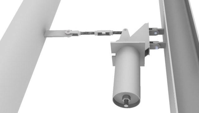
3 AAA Technology & Specialties Co., Inc. 2Page 2 An EQUALBALANCE Hanger is a reliable counter-balance with the counterbalance force imposed by a spring coil. By using varying lever arms and spring coil load variation, an accurate constant supporting force is obtained. EQUALBALANCE Hangers provide constant support forces for piping systems which move vertically due to thermal expansion or contraction and where the transfer of support load to adjacent hangers and/or equipment is not acceptable. These hangers have been thoroughly time-tested as evidenced by years of successful operation in a large number of steam generating stations, oil refineries and chemical plants throughout the world. EQUALBALANCE hangers are available in seven different types and a broad variety of sizes to accommodate a wide range of loads, movements and hanger arrangements. HOLE FOR REMOVABLE TOP PIN SPRING COIL LOW FRICTION BEARING SPRING ROD CONSTRUCTION All EQUALBALANCE Hangers are manufactured in conformance SPRING CASING with government regulations and industry codes where applicable. Among these are the American Society of Mechanical Engineers - Codes for Pressure Piping (ASME B31.1 Code for Power Piping and ASME B31.3 Code for Chemical Plant and Petroleum Refinery Piping), the Manufacturers Standardization Society Standards SP - 58 and SP - 69 and the U.S. Government Federal Specification WWW - H for pipe hangers and supports. Materials and workmanship of the High Quality along with conservative designs are used to improve the operating life of the EQUALBALANCE Hangers in severe service applications. Spring coils of a conservative design are used to guard against any relaxation while in use. All pivot points including lower load rod pivot, are equipped with lifetime, low-friction bearings mounted in accurately constructed and machined frames and assemblies. TRAVEL STOPS Each EQUALBALANCE Hanger has built-in upper and lower stops to limit the travel a minimum of 12 1/2% beyond the specified actual travel range. Further, the hanger is pinned at the preset position (initial travel position) for the purpose of facilitating installation at a specified position and making it a rigid hanger for the purposes of hydrostatic testing. Please be aware that the EQUALBALANCE Hanger will only function properly when the temporary stop has been removed and the hanger load rod is adjusted properly to enable the unit to operate within the specified range of travel. An movement indicator arrow, attached to the movable pivot arm, indicates the travel position at all times. HYDROSTATIC TEST LOADS Each EQUALBALANCE Hanger is capable of supporting hydrostatic test loads equal to 1.5 times the largest tabulated load for that hanger size range. LOAD ADJUSTMENT LOAD ROD Each EQUALBALANCE Hanger is supplied with a load adjusting nut which permits up to a 10 percent increase or decrease in load-carrying capacity. However, since each EQUALBALANCE Hanger is tested on a hydraulic press in our plant and pre-set to a specified load and tested over the range of movement specified by our customer, it is recommended that no field load adjustment be made until it is determined by stress analysis or load cell that a change is necessary. In the event that changes are made, the balance of loads and pipe stresses may be altered. Please remember that turnbuckle adjustments only change the position of the load arm and do not affect the supporting force of the EQUALBALANCE Hanger.

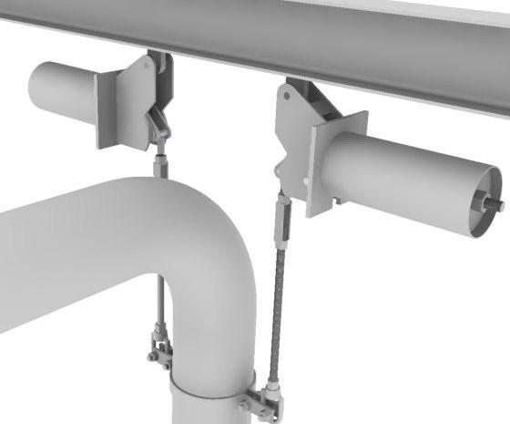
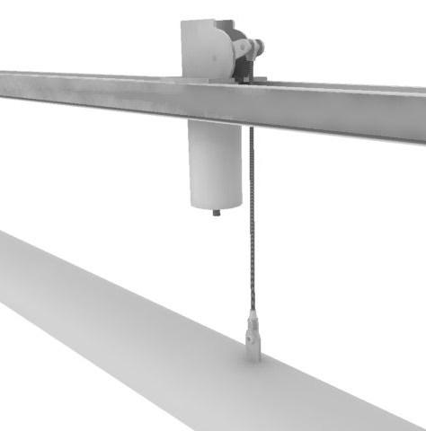
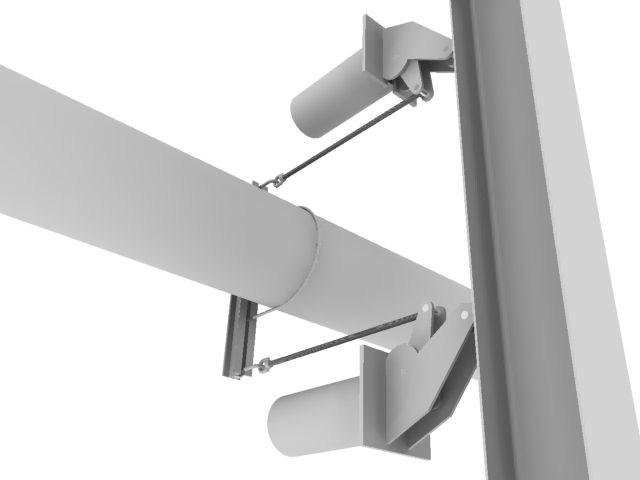
4 Page info@aaatech.com STANDARD HANGERS The dimensions shown on the following pages are for convenience in selecting the proper type and size EQUALBALANCE hangers for your specific requirement. Depending upon the customers special requirements, the dimensions of the hanger manufactured may be slightly different than the dimensions provided in the catalog. Load to be carried as well as actual travel and direction of travel influence the physical design features of the final hanger. Since the load supporting capacity of all sizes of EQUALBALANCE hangers is inversely proportional to the travel magnitude, specifying more travel than necessary will result in a larger and more expensive hanger than actually required. SPECIAL HANGERS The drawings and tabulated data on the following pages depict the hanger designs which cover a large percentage of installations. In addition, a number of typical industrial constant spring hanger applications are shown on pages 4 and 5. If constant designs other than those illustrated in this catalog are required, our staff will be pleased to develop custom designs for your review and approval. In addition to the types and sizes of EQUALBALANCE hangers shown in detail in this catalog, the following can also be furnished upon request: A. Hangers to handle loads and/or travels beyond the standard ranges shown on pages B. EQUALBALANCE hangers with Neoprene-coated coils and galvanized exposed surfaces can be provided for use in corrosive environments. C. Custom top connections. D. Extra long lower load rods. E. Custom gap turnbuckles. F. Nonstandard materials. G. Custom load rod connections. INSTALLATION and SETTING EQUALBALANCE hangers can be installed by an average field worker with little to no difficulty. Placing the hangers in position and adjusting them to carry the desired load at the desired position is easily accomplished. All suspension style EQUALBALANCE hangers are designed so that the top connection can be removed in the field and can be bolted or welded separately to the supporting structure or suspended from rods. The hanger frame and casing can then be easily attached by reinserting the removable pin or pins. All EQUALBALANCE hangers have upper and lower stops to limit travel. Hangers with downward travel (pipe moves downward from installed to operating) will be locked (pinned) in the installed position in order to handle the hydrostatic test loading. Hangers with upward travel (pipe moves upward from installed to operating) will be locked (pinned) in the installed position which eliminates the necessity of pulling the hanger to the bottom of the travel when connecting the load rod in the field. All hydrostatic tests should be performed with the constant locked in the installed position. If desired, EQUALBALANCE hangers can be supplied locked at any desired point in the total travel range. Just specified the desire locking location when ordering. In all cases, the lock pin can easily be removed by hand by adjusting the turnbuckle on the load carrying rod until the pin is loose. This lock must be removed at the final adjustment or the hanger will not function. After the hydrostatic test is performed, the final adjustment should consist of turning the turnbuckle so that the hanger is not resting on the travel stop in the installed position. An inspection should be made after the system is in service to insure that the travel indicator is located at the operating position on the travel scale.


 and travel indicator plate (illustrated below) mounted on the hanger frame indicate the position of travel.")
5 AAA Technology & Specialties Co., Inc. Page 4 When the supported piping system is required to be re-hydrotested after start-up, all EQUALBALANCE hangers should be repinned in the installed position. All hangers should be adjusted, by the turnbuckle, until the pin holes are aligned and the pin can be re-inserted. In a piping system where cold spring must be utilized to align a piping system or to pre-stress it, planning ahead is encouraged so that the line can be supported before, during and after the cold spring exercise by adjusting the turnbuckle within its limits. Larger opening turnbuckles are available upon request. EQUALBALANCE hangers are supplied with 6 turnbuckles, unless the customer requests a longer opening. TRAVEL INDICATION The indicator arrow (mounted on the pivot arm) and travel indicator plate (illustrated below) mounted on the hanger frame indicate the position of travel. The arrow should point to a point on the travel indicator plate under all operating conditions. For hangers with downward travel as the pipe moves from installed to operating, the indicator arrow must be near the top of the range when the load rod is properly adjusted for the installed position. For hangers with upward travel as the pipe moves from installed to operating, the indicator arrow must be near the bottom of the range when the load rod is properly adjusted for the installed position.

6 Page info@aaatech.com FIELD LOAD ADJUSTMENT The support load on each EQUALBALANCE hanger is set on a hydraulic press and calibrated with a load cell before shipment. Adjustment of the hanger load will modify the load supported by the hanger and may invalidate the design engineer s stress calculations. However, in order to provide for cases where the load to be supported is different from the specified load or where a change in hanger location becomes necessary, the EQUALBALANCE hanger is provided with a load adjustment mechanism on the tail of the spring rod. Field adjustment can increase or decrease the specified load by as much as 10 percent. As a result, an EQUALBALANCE hanger carrying 2,000 lbs can be field adjusted to carry loads from 1,800 to 2,200 lbs. To adjust the load, loosen the jam nut to which the load sleeve is attached. Turn the main spring rod nut clockwise to increase the load and counter clockwise to decrease the load. When the jam nut is returned to its original position against the main nut, the amount of load adjustment can be read from the position of the indicator on the load scale. When adjustment is completed the jam nut must again be tightened snuggly. The extreme end of the spring rod is equipped with a permanent stop to prevent the complete removal of both the jam nut and sleeve, and the main spring rod nut. Under no circumstances should an attempt be made to remove these nuts from the end of the spring rod.


7 AAA Technology & Specialties Co., Inc. Page 6 S-TYPE D-TYPE B-TYPE
8 Page info@aaatech.com V-TYPE VB-TYPE VBS-TYPE U-TYPE
9 AAA Technology & Specialties Co., Inc. Page 8 EQUALBALANCE Hanger Selection Table Hanger Size Selection Instructions: Find the desired total travel on the top data row of the table below. From the desired total travel, move down the load column to the first load equal to or larger than the required load. The correct hanger size will be found in the 'size' column horizontally across to the far left from this load. Although each EQUALBALANCE hanger will accommodate a small amount of travel beyond its rated total travel, it is good design to select a hanger that provides a larger travel than expected. In cases where travel cannot be accurately calculated, a more generous total travel should be used to size the hanger. TOTAL TRAVEL (Inches) 1 1/ / / / / / / / / /
10 Page info@aaatech.com EQUALBALANCE Hanger Selection Table Hanger Size Selection Instructions: Find the desired total travel on the top data row of the table below. From the desired total travel, move down the load column to the first load equal to or larger than the required load. The correct hanger size will be found in the 'size' column horizontally across to the far left from this load. Although each EQUALBALANCE hanger will accommodate a small amount of travel beyond its rated total travel, it is good design to select a hanger that provides a larger travel than expected. In cases where travel cannot be accurately calculated, a more generous total travel should be used to size the hanger. TOTAL TRAVEL (Inches) / / / / / / / / /
11 AAA Technology & Specialties Co., Inc. Page 10 EQUALBALANCE Hanger Selection Table Hanger Size Selection Instructions: Find the desired total travel on the top data row of the table below. From the desired total travel, move down the load column to the first load equal to or larger than the required load. The correct hanger size will be found in the 'size' column horizontally across to the far left from this load. Although each EQUALBALANCE hanger will accommodate a small amount of travel beyond its rated total travel, it is good design to select a hanger that provides a larger travel than expected. In cases where travel cannot be accurately calculated, a more generous total travel should be used to size the hanger. Total Travel (Inches) 2 1/ / / / / / / / /
12 Page EQUALBALANCE Hanger Selection Table Hanger Size Selection Instructions: Find the desired total travel on the top data row of the table below. From the desired total travel, move down the load column to the first load equal to or larger than the required load. The correct hanger size will be found in the 'size' column horizontally across to the far left from this load. Although each EQUALBALANCE hanger will accommodate a small amount of travel beyond its rated total travel, it is good design to select a hanger that provides a larger travel than expected. In cases where travel cannot be accurately calculated, a more generous total travel should be used to size the hanger. Total Travel (Inches) 11 1/ / / / / / / / /

13 AAA Technology & Specialties Co., Inc. Page 12 S TYPE SINGLE SUSPENSION The Type S EQUALBALANCE single suspension point hanger is designed for use with a single rod or welding lug top connection. When the S- type EQUALBALANCE hanger is suspended by a single rod, the entire hanger can be rotated 360º to avoid interference. When headroom is limited, an alternate top connection, a lug, can be furnished which attaches directly to the building structure. The Type S EQUALBALANCE hanger is available for support loads from 19 lbs. through 20,117 lbs. and for total travels from 1 ½ through 20 inches. TOTAL TRAVEL STD. ROD DIA. B E F G K P Q APPROX. UNIT WEIGHT (LBS.) /2-20 1/2 & 5/8 5 9/ / /16 2 7/8 2 5/8 9/16 7/ /2-20 1/2-1 1/4 9 5/8 15 1/2 4 1/4 4 1/8 3 3/8 7/8 1 1/ /8-1 1/4 11 3/4 16 9/16 4 5/8 4 5/8 3 5/ / /2-20 3/4-1 1/4 12 3/4 17 9/16 5 1/16 4 5/8 4 1/8 1 3/16 1 1/ /2-20 3/ /8 6 1/8 6 1/4 5 5/8 1 7/ / /8 6 1/2 6 1/2 5 5/8 1 9/
14 Page S TYPE SINGLE SUSPENSION DIMENSIONS "H" AND "L" ROD DIAMETER DIM. 1/2 5/8 3/ /4 1 1/2 1 3/ /4 2 1/2 2 3/4 H 3/4 1 1/8 1 1/4 1 1/ /4 2 3/ L 4 3/8 4 5/8 4 7/8 5 1/2 6 1/4 6 3/4 7 1/ / /8 Dimension "L" to be e=incased by 3" for 12" gap turnbuckle. DIMENSION "A" 1 1/ / /8 6 5/ / /8 3 11/16 3 9/16 3 9/16 3 9/16 3 9/16 3 9/16 3 9/16 3 9/16 3 9/ /16 8 1/8 7 3/4 7 7/ /16 6 3/16 5 1/2 4 7/8 4 3/8 4 3/8 4 3/8 4 3/8 4 3/8 4 3/8 4 3/ /4 10 7/ /16 9 7/ /16 8 3/16 7 1/2 6 7/8 6 1/4 5 9/ / /4 11 5/ /8 9 11/16 9 1/16 8 7/16 7 3/4 7 1/8 6 1/2 5 13/ / / /2 12 7/8 12 1/4 11 9/ / /16 9 5/ /8 7 3/4 7 1/16 6 7/ / / / / / /4 10 1/8 9 1/2 8 13/16 8 3/16 7 9/16 *Dimension "A" is for down travel (cold to hot). For up travel, Increase dimension by length of total travel DIMENSION "N" 1 1/ / /16 1 1/16 1 9/ / / /16 4 9/16 5 7/16 6 5/16 7 1/ / / / / / /4 1 5/ / /8 4 3/8 5 1/8 5 3/4 6 1/2 7 1/8 7 7/8 8 1/2 9 1/4 9 7/ / /16 2 3/ /16 3 9/16 4 3/ /16 5 9/16 6 3/ /16 7 9/ / /16 9 9/ /16 2 3/ /16 3 9/16 4 5/16 5 1/ /16 6 7/16 7 1/ /16 8 7/16 9 3/ / /2 1 7/8 2 1/2 3 1/8 3 3/4 4 3/ /8 6 1/4 6 7/8 7 1/2 8 1/8 8 3/ /8 3 3/ /8 5 1/ /8 7 1/4 7 7/8 8 5/8 9 1/4 DIMENSION "D" (MAXIMUM) 1 1/ / / / / / / / / / / / / / / / / /8 21 3/ /4 23 3/8 24 1/8 24 7/8 25 1/2 26 1/4 26 7/8 27 5/8 28 1/ / / / /4 25 3/ /4 27 3/ /4 29 7/ / / / / / / / / / / / / / / /4 32 5/8 33 1/4 33 7/8 34 1/2 35 1/8 35 3/4 36 3/ /8 38 1/4 38 7/8 39 1/ / /4 39 3/ /8 41 3/ /8 43 1/ /8 DIMENSION "C" 1 1/ / /16 1 9/16 1 9/16 1 9/16 1 9/16 1 9/16 1 9/ /16 3 5/ /16 4 5/8 5 1/4 5 7/8 6 5/ /16 1 9/16 1 1/2 1 1/2 1 1/2 1 1/2 1 1/2 1 1/2 1 5/8 2 5/ /16 3 9/16 4 1/4 4 7/8 5 1/ /16 2 7/16 2 7/16 2 7/16 2 7/16 2 1/2 2 7/16 2 7/16 2 3/16 2 7/16 2 1/2 3 1/8 3 3/4 4 3/ /2 3 1/2 3 1/2 3 1/2 3 1/2 3 1/2 3 1/2 3 1/2 3 1/2 3 1/2 3 1/2 3 1/ / / / / / / / / / / / / / /16 4 5/16 4 5/16 4 5/16 4 5/16 4 5/16 4 5/16 4 5/16 4 5/16 4 5/16 4 5/16 4 5/16

15 AAA Technology & Specialties Co., Inc. Page 14 D TYPE S 1-66 DOUBLE SUSPENSION The Type D EQUALBALANCE double suspension point hanger is designed to be able to support the heaviest support loads and the longest actual travels. This D-type EQUALBALANCE is furnished with two lugs welded on the top of the frame plate. The lugs can be oriented either along the axis of the hanger casing or perpendicular to the axis of the hanger casing. Mating attachments can be provided with rods and clevises and beam brackets. The Type D EQUALBALANCE double suspension point hanger is available for support loads from 19 lbs through 56,252 lbs and for total travels from 1 ½ through 20 inches. TOTAL TRAV- EL STD. ROD DIA. B C E F G H N P W X Y /2-10 1/2 & 5/8 5 9/16 1/2 12 3/ /16 2 7/ /16 9/ /2 1/2 35 APPROX. UNIT WEIGHT (LBS.) /2-3 7/8 5/8-1 1/4 3/4 4 5/8 1 1/2 4 3/4 3/4 8 5/8 15 1/2 4 1/4 4 1/8 5 1/2 7/ /8-3/4 3/4 4 7/ /2 1/ /8 5/8-1 1/4 3/4 5 7/16 1 1/2 5 3/4 3/4 11 3/4 16 9/16 4 5/8 4 5/ /2-11 5/8-3/4 3/4 5 11/ /2 1/2 2 1/2-7 7/8 3/4-1 1/4 3/4 8 3/16 1 1/2 8 3/4 3/4 12 3/4 17 9/16 5 1/16 4 5/ / /8-3/4 3/4 8 7/ /2 1/2 2 1/2-7 7/8 3/ /4 8 3/4 2 1/4 9 3/ /8 6 1/8 6 1/4 9 1/4 1 7/ / /4 1 1/2 9 3/4 3/ / /4 1 1/4 9 1/4 2 1/4 10 3/ /8 6 1/2 6 1/2 10 3/4 1 5/ /4-1 1/ /4 1 1/2 10 3/4 3/ /8 1 1/4-2 1/2 1 1/2 9 1/16 2 3/4 9 1/2 3/ / /8 1 5/ /2 1 1/4 9 1/16 1 3/4 10 1/2 3/ /8 1 1/2-2 1/4 1 1/2 9 13/16 2 3/4 10 1/2 3/ /16 7 1/4 8 3/4 11 3/ /4-1 1/2 1 1/4 9 13/16 1 3/4 11 1/2 3/ /8 1 1/2-2 1/2 1 3/4 11 1/8 2 3/4 12 3/ /8 7 7/8 8 3/4 11 3/ /4-1 3/4 1 1/2 11 1/8 2 1/4 12 1/2 3/ /8 1 3/4-2 3/4 1 3/4 10 7/8 2 3/4 12 3/ /8 8 3/ /4 2 1/ / /4 10 7/8 2 1/4 12 1/2 3/ / / /16 3 1/ /16 8 3/ / /2-2 1/ /16 2 3/4 13 3/
16 Page D TYPE S 1-66 (Continued) DOUBLE SUSPENSION (For Sizes 1 through 66) DIMENSION "L" DIM. ROD DIAMETER 1/2 5/8 3/ /4 1 1/2 1 3/ /4 2 1/2 2 3/4 3 L 4 3/8 4 5/8 4 7/8 5 1/2 6 1/4 6 3/4 7 1/ / /8 10 1/2 Dimensions "L" to be increased by 3" for 12" gap turnbuckle. DIMENSION "A" 1 1/ / /8 6 13/16 6 7/16 6 1/8 5 1/2 4 13/16 4 3/16 3 9/ /16 2 5/16 1 5/ /8 2 11/16 3 1/16 3 7/16 3 3/4 4 1/8 4 1/2 4 7/8 5 1/ /16 7 5/8 7 1/4 6 15/16 6 5/16 5 5/ /8 3 3/4 3 1/8 2 7/ / /16 3 1/2 3 7/8 4 1/4 4 5/8 4 15/16 5 5/ / /4 8 15/16 8 9/ /16 7 5/ / /8 4 3/4 4 1/16 3 7/ /16 4 1/8 4 1/2 4 7/8 5 1/4 5 9/ /16 6 5/16 6 5/ /8 10 3/4 10 1/8 9 1/2 8 13/16 8 3/16 7 9/ /16 6 1/4 5 5/ /8 3 11/16 4 1/16 4 3/8 4 3/4 5 1/8 5 1/2 5 13/ / /8 10 3/4 10 1/16 9 7/ /16 8 3/16 7 1/2 6 7/8 6 1/4 5 9/ /16 5 5/ / /8 6 3/4 7 1/ / / / / /16 9 3/4 9 1/8 8 1/2 7 7/8 7 1/4 6 9/ /16 5 1/4 5 11/16 6 1/16 6 7/16 6 3/ / /2 12 7/ /4 11 9/ / /4 9 5/ /8 7 3/4 7 1/16 6 7/16 5 3/4 6 3/16 6 9/ /16 7 1/ / / / /8 11 3/4 11 1/ / /16 9 3/16 8 1/2 7 7/8 7 1/4 7 9// /16 8 5/16 8 5/ / / / /4 13 5/ / / / /8 9 3/4 9 1/8 8 1/2 8 13/16 9 3/16 9 9/16 9 7/ / / /8 15 1/2 14 7/8 14 1/4 13 9/ / / / /8 9 3/4 9 1/16 8 7/ /16 9 1/ / / /8 16 1/2 15 7/8 15 1/4 14 9/ / / / /8 10 3/4 10 1/16 9 7/ / /8 *Dimension "A" is for down travel (cold to hot). For up travel, Increase dimension by length of total travel DIMENSION "D" (MAXIMUM) 1 1/ / / / / / / /4 20 1/2 21 1/ /4 23 9/ / / / /8 27 3/8 28 1/8 28 7/ / / / / / / / / / /8 25 1/8 25 7/8 26 5/8 27 7/ / / / /2 31 1/ /4 33 9/ / / /4 23 1/8 23 1/2 24 1/ /4 26 9/ / / / /8 30 3/8 31 3/ / / / / /4 36 1/ / / / /2 27 1/ /4 29 1/2 30 5/ / / / /8 34 1/8 34 7/8 35 5/8 36 7/ / / /8 33 1/ / / /8 36 1/8 36 7/8 37 5/8 38 7/ / / /4 41 1/2 42 1/ /4 44 9/ / / / / /4 41 1/2 42 1/4 43 1/ / / /8 46 1/8 46 7/8 47 5/8 48 3/8 49 3/ / / / / / / / / /4 45 1/2 46 1/ / / / / /8 51 5/8 52 3/ / / / / / /4 48 1/2 49 1/ / / / / /8 54 5/8 55 3/ / /2 47 1/ /4 49 1/2 50 5/ / / / /8 54 1/8 54 7/8 55 3/4 56 9/ / / / / /8 49 5/8 50 3/8 51 3/ / / / / /4 56 1/2 57 1/4 58 1/ / / /4 53 1/2 54 1/4 55 1/ / / / /8 58 7/8 59 5/8 60 7/ / / / /2 64 1/4 65
 67 6-20 1 3/4-3 22 46 1/4 9 1/2 10 7/16 2 1/8 3/4 2 1/4 2 1/2 1 3/4 7 2475 68 6-20 1 3/4-3 22 47 9 1/2 10 7/16 2 1/8 3/4 2 1/4 2 1/2 1 3/4 7 2500 69 6-20 1 3/4-3 1/4 22 50 9 1/2 10 7/16 2 1/8 3/4 2")
17 AAA Technology & Specialties Co., Inc. Page 16 D TYPE S DOUBLE SUSPENSION TOTAL TRAVEL STD. ROD DIA. B E F G C J P Q U W APPROX. UNIT WT (LBS.) / /4 9 1/2 10 7/16 2 1/8 3/4 2 1/4 2 1/2 1 3/ / /2 10 7/16 2 1/8 3/4 2 1/4 2 1/2 1 3/ /4-3 1/ /2 10 7/16 2 1/8 3/4 2 1/4 2 1/2 1 3/ / /8 9 1/2 10 7/16 2 1/8 3/4 2 1/4 2 1/2 1 3/ / /8 9 7/8 12 9/16 2 3/ / /4 8 7/ / /4 9 7/8 12 9/16 2 3/ / /4 8 7/ / /8 10 5/8 12 9/16 2 5/ / /4 8 7/ / /8 10 5/8 12 9/16 2 5/ / /4 8 7/ DIMENSION "L" ROD DIA. DIM. 1 1/4 1 1/2 1 3/ /4 2 1/2 2 3/ /4 3 1/2 3 3/4 4 L 6 1/4 6 3/4 7 1/ / /8 10 1/2 11 1/2 11 3/4 12 1/2 13 1/4 Dimensions "L" to be increased by 3" for 12" gap turnbuckle. Rod Take-out = L + A* DIMENSION "A" /8 18 3/4 18 1/8 17 1/ / / / /8 14 1/4 13 5/ / / / / / /8 18 3/4 18 1/ / /4 16 1/8 15 1/2 14 7/8 14 1/4 13 9/ / / /4 21 1/8 20 1/ / / / / /4 16 5/ / / / / /4 Dimensions "A" is for down travel (cold to hot). For up travel, increase dimension by length of total travel. DIMENSION "C" DIMENSION "I" AND "N" DIM I 14 7/8 15 7/8 16 7/8 17 7/8 18 7/8 19 7/ /8 15 3/8 16 3/8 17 3/8 18 3/8 19 3/8 N 13 15/ / / / / /16 I 14 7/8 15 7/8 16 7/8 17 7/8 18 7/8 19 7/ /8 16 3/8 17 3/8 18 3/8 19 3/8 20 3/8 N 14 3/ / / / / /16 I 14 7/8 15 7/8 16 7/8 17 7/8 18 7/8 19 7/ /8 17 3/8 18 3/8 19 3/8 20 3/8 21 3/8 N 14 13/ / / / / /16
18 Page D TYPE S (Continued) DOUBLE SUSPENSION DIMENSION "D" (MAXIMUM) /8 61 1/8 61 7/8 62 5/8 63 7/ / / / /2 67 1/ /4 69 1/2 70 5/ / /8 61 7/8 62 5/8 63 3/8 64 3/ / / /2 67 1/ /4 69 1/2 70 5/ / / /8 64 7/8 65 5/8 66 3/8 67 3/ / / /2 70 1/ /4 72 1/2 73 5/ / / / /4 67 1/2 68 5/ / / / /8 72 1/8 72 7/8 73 5/8 74 7/ / / / /8 71 1/8 71 7/ / / / / /4 76 1/2 77 1/ /4 79 9/ / / /2 74 1/ /4 76 9/ / / / / /8 81 1/8 81 7/ / / / /8 70 1/8 70 7/8 71 5/8 72 7/ / / / /2 76 1/ /4 78 9/ / /8 70 5/8 71 3/8 72 1/ / / / / /4 77 1/2 78 1/4 79 1/ / /16 D TYPE S DOUBLE SUSPENSION Rod Take-out = A* - K TOTAL TRAVEL STD. ROD DIA. B E F G C J K M Q U Z / / / /8 1 1/ / /4-4 1/4 2 3/4-4 1/ / / /8 55 1/8 9 1/2 9 7/ /8 3 5/8 1 1/4 1 1/4 3 x Rod Dia. (Min.) /4 2 3/ / / /4 9 7/ /8 1 1/ / APPROX. UNIT WT (LBS.) / /2-4 1/ / / /8 1 1/ / /4-4 1/ / /8 10 5/ /8 1 1/ / /4-4 1/ / /8 10 5/ /8 1 1/ /
19 AAA Technology & Specialties Co., Inc. Page 18 D TYPE S (Continued) DOUBLE SUSPENSION DIMENSION "Y" DIMENSION "C" ROD DIA. 2 1/2 2 3/ /4 3 1/2 3 3/ / /2 8 1/2 9 1/2 9 1/ MIN. TO 15 TOTAL TRAVEL /8 18 7/8 19 7/8 20 7/8 21 7/8 22 7/ /8 19 7/8 20 7/8 21 7/8 22 7/8 23 7/8 DIMENSION "I" AND "N" DIM. MIN. TO 15 TOTAL TRAVEL I 14 7/8 15 7/8 16 7/8 17 7/8 18 7/8 19 7/8 N 13 7/8 14 7/8 15 7/8 16 7/8 17 7/8 18 7/8 I 14 7/8 15 7/8 16 7/8 17 7/8 18 7/8 19 7/8 N 13 5/8 14 5/8 15 5/8 16 5/8 17 5/8 18 5/8 I 14 7/8 15 7/8 16 7/8 17 7/8 18 7/8 19 7/ /8 20 7/8 21 7/8 22 7/8 23 7/8 24 7/8 N 13 5/8 14 5/8 15 5/8 16 5/8 17 5/8 18 5/8 For travels over 15", dimensions "I" & "N" are approximate. These dimensions will vary to match the top connections DIMENSION "A" /4 27 1/4 26 1/ /4 24 3/ /4 22 1/4 22 9/ / /4 24 1/ /4 26 3/4 26 1/2 25 1/2 25 1/4 24 3/ /4 22 1/4 22 9/ / /4 23 5/ /4 26 3/ /2 24 3/4 24 3/ /4 20 3/4 22 9/ / /4 23 5/ /4 30 3/4 30 1/ /4 28 1/4 27 1/2 25 1/4 24 3/4 25 1/ / /4 26 1/ / /4 27 3/4 27 1/2 25 3/4 24 1/4 25 1/ / /4 26 1/ /2 30 1/4 29 3/ /4 27 1/4 27 9/ / /4 27 5/ /2 29 3/4 29 1/ /4 26 3/4 27 9/ / /4 27 5/8 Dimension "A" is for down travel (cold to hot). For up travel, increase dimension by length of total travel /8 62 5/8 63 3/8 64 3/ / / / / /4 69 1/2 70 5/ / / /8 65 5/8 66 3/8 67 3/ // / / / /4 72 1/2 73 5/ / / /4 67 1/2 68 5/ / / / /8 72 1/8 72 7/8 73 5/ / / / /8 71 7/8 72 5/8 73 7/ / / /4 76 1/2 77 1/ / / / /4 76 9/ / / / /8 80 3/8 81 1/8 81 7/8 82 5/8 83 7/ /8 72 7/ / / /4 75 1/2 76 1/ /4 78 9/ / / / / /4 77 1/2 78 1/4 79 1/ / /16

20 Page B TYPE HORIZONTAL BASE The horizontal base type EQUALBALANCE hanger is designed for use in limited headroom applications where available structural support members are above and close to the pipe. The B-type EQUALBALANCE may be mounted on top of the supporting steel or inverted beneath the support steel in a trapeze arrangement. The load rod connection is a bushing or a spherical bearing if desired to permit the support rod to swing in both directions. The EQUALBALANCE type B hanger is available for support loads from 26 lbs through 90,627 lbs and for total travels TOTAL TRAVEL J STD. ROD DIA. B C E F G H O M N X APPROX. UNIT WEIGHT (LBS.) /2-20 1/2 & 5/8 5 9/16 4 5/8 12 3/ /16 2 7/8 9/16 4 1/ /16 1/ / / /2 4 1/4 4 1/8 9/16 5 3/ /8 3/ / /4 7 1/2 16 9/16 4 5/8 4 5/8 9/16 6 1/4 2 1/2 1 13/16 3/ /8-1 1/4 12 3/4 8 3/8 17 9/16 5 1/16 4 5/8 13/ /2 2 1/16 3/ /8-1 1/ /2 24 5/8 6 1/8 6 1/4 13/16 8 1/ /2 1/ /4-1 3/ /8 6 1/2 6 1/2 13/16 8 3/ / /8 30 1/ /16 9 1/ /16 5/ / / /16 7 1/4 8 7/8 1 1/ / /16 3/ /4-2 1/ /8 34 7/8 7 7/8 8 7/8 1 1/ /2 4 1/2 3 5/8 3/ /2-2 1/ /8 35 7/8 8 3/ / /2 4 1/2 3 7/ /2-2 3/ / /16 8 3/ / / / /4 9 1/2 10 1/2 1 1/ / / / /2 10 1/2 1 1/ / / / /2 10 1/2 1 1/ / / /4-3 1/ /8 9 1/2 10 1/2 1 1/ / / /4-3 1/ /8 9 7/8 12 1/2 1 3/8 16 3/ /4 1 1/ /2-3 1/ /4 9 7/8 12 1/2 1 3/8 16 3/ /4 1 1/ / /8 10 5/8 12 9/16 1 3/8 16 3/ /8 1 1/ /4-4 1/ /2 54 5/8 10 5/8 12 9/16 1 3/8 16 3/ /8 1 1/4 4500

21 AAA Technology & Specialties Co., Inc. Page 20 V TYPE VERTICAL The Type V EQUALBALANCE single suspension point hanger is designed for use with a single rod or welding lug top connection and can be used when space limitations restrict the use of a model with a horizontal spring casing.. When the V-type EQUALBALANCE hanger is suspended by a single rod, the entire hanger can be rotated 360º to avoid interference. When headroom is limited, an alternate top connection, a lug, can be furnished which attaches directly to the building structure. The Type V EQUALBALANCE hanger is available for loads from 10 lbs through lbs and for travels from 1 ½ through 20 inches. TOTAL TRAVEL STD. ROD DIA. A* B E F G K P Q APPROX. UNIT WEIGHT (LBS.) /2-2 3/8 1/2-5/8 2 1/2-20 1/ /8 5/ /8-3/ /8 5/8-1 1/ /8-3/ /8 5/8 1 1/ / / /4 6 1/2-20 5/8-1 1/ /8 1 1/4-1 3/ / /8 1 1/ / /4-1 1/ /8 1 1/ / /4-1 1/ /8 1 3/4-2 1/ /4-1 3/ /8 1 3/4-2 1/ /4-1 3/ / / /2-2 1/ /8 2 1/4-3 1/ /4-3 1/ /8 2 1/2-3 3/ / /8 2 3/ / /16 5 9/ /8 3 11/ /16 2 5/8 9/16 7/ /8 9 5/6 13 7/8 4 1/4 4 3/16 3 3/8 7/8 1 1/ /4 14 3/4 4 5/8 4 5/8 3 5/ / / /4 15 1/2 5 1/16 4 5/8 4 1/8 1 3/16 1 1/ / /8 6 1/8 6 1/4 5 5/8 1 7/ / /2 6 1/2 5 5/8 1 9/ / / /2 1 9/16 2 1/ / /8 7 3/8 8 7/8 5 1/ / / /4 7 7/8 8 7/8 6 1/ / / / /4 2 1/4 2 3/ / /8 8 3/ /8 2 1/ / /4 9 1/2 10 1/2 7 3/4 2 1/4 3 1/ / /2 9 7/8 12 1/2 8 3/8 2 1/ / /2 10 5/8 12 1/2 8 5/8 2 5/8 4 1/4 4475
22 Page V TYPE VERTICAL DIMENSION "H" AND "L" ROD DIA. DIM. 1/2 5/8 3/ /4 1 1/2 1 3/ /4 2 1/2 2 3/ /4 3 1/2 3 3/4 4 H 3/4 1 1/8 1 1/4 1 1/ /4 2 3/ /2 N/A N/A N/A N/A L 4 3/8 4 5/8 4 7/8 5 1/2 6 1/4 6 3/4 7 1/ / /8 10 1/2 11 1/2 11 3/4 12 1/2 13 1/4 Dimensions "L" to be increased by 3" for 12" gap turnbuckle. DIMENSION "N" 1 1/ /16 6 1/8 4 13/16 5 9/16 6 5/16 7 1/16 7 7/8 8 5/8 9 3/8 10 3/ / / / / /4 15 1/2 16 5/ / / /16 7 3/8 5 9/16 6 5/16 7 1/16 7 7/8 8 5/8 9 3/8 10 3/ / / / / /4 15 1/2 16 5/ / / /8 11 1/8 12 3/4 7 1/16 7 7/8 8 5/8 9 3/8 10 3/ / / / / /4 15 1/2 16 5/ / / /8 11 1/8 12 3/4 14 3/8 7 7/8 8 5/8 9 3/8 10 3/ / / / / /4 15 1/2 16 5/ / / / / /4 8 5/8 9 3/8 10 1/8 10 7/ / / / /4 15 1/2 16 5/ / / / / / /4 15 5/8 9 3/8 10 1/8 10 7/ / / / /4 15 1/2 16 5/ / / / / /8 14 7/ / / / / / /8 15 5/8 16 3/8 17 3/ / / / /8 14 7/ / / / / / / /8 15 5/8 16 3/8 17 3/ / / / / / / /8 11 7/ / / / / /4 16 1/2 17 1/ / / / / / / /8 19 1/4 13 7/ / / /4 16 1/2 17 1/ / / / / /4 16 7/ /8 14 3/ / /4 16 1/2 17 1/ /4 19 1/2 20 5/ / / / / /4 21 1/ / / /8 18 1/8 18 7/8 19 5/8 20 7/ / / / /8 19 1/4 20 3/8 21 1/2 22 9/ / /8 18 1/8 18 7/8 19 5/8 20 7/ / / / /8 19 1/4 20 3/8 21 1/2 22 9/ / /8 18 1/8 18 7/8 19 5/8 20 7/ / /16 DIMENSION "D" (MAXIMUM) SHORT TRAVEL STANDARD TRAVEL 1 1/ / / /8 22 1/ / / / / /2 26 1/8 26 3/4 27 7/ / / / /8 31 1/ / /8 25 7/8 25 9/ / /8 27 1/2 28 1/8 28 3/4 29 7/ / /4 31 3/ /8 33 5/ / / / / /8 30 1/ / /8 29 9/ / / / / / / / / /8 37 1/ / / /8 33 3/4 35 7/ / /8 32 3/4 33 7/ / / / /8 37 1/ / / / / / / /8 42 3/ /2 40 1/4 40 7/8 41 9/ / / / /8 44 3/4 45 3/8 46 1/ / / / / / /4 49 9/ / / / / / / /8 51 5/ / / / / /4 48 3/8 49 9/ / / / /8 51 1/ / / / /8 54 1/2 55 1/8 55 3/4 56 7/ /4 52 7/8 54 1/ / / /8 54 1/4 54 3/4 55 7/ / / /2 58 1/8 58 3/4 59 3/ / / / / / / / / /8 59 1/4 59 7/8 60 9/ / / /2 63 1/ / / / /4 59 7/ / /4 61 3/ / / / /8 65 1/ / / / / / / / /4 67 7/8 68 1/2 69 3/ / / / / / / /2 78 3/8 79 1/4 80 1/2 78 3/ /8 80 1/4 80 7/8 81 9/ / / / / / /8 87 3/4 88 5/8 89 1/2 87 1/2 88 1/8 88 3/4 89 3/8 90 1/ / / / /8 83 5/ / /8 86 3/4 85 7/8 86 1/4 86 7/8 87 1/2 88 5/ / /2 90 1/8 SHORT TRAVEL STANDARD TRAVEL SHORT TRAVEL W a (deg) TRAV. ARC (deg) b STANDARD TRAVEL TOTAL TRAVEL (in) W a (deg) b (deg) /2-2 3/ x T /2-10 T / x T T / x T T / x T T / x T /2-14 T / x T T / x T /2-14 T / x T /2-14 T / x T T / x T T / x T T / x T T / x T T / x T T These dimensions may be interpolated, except across short and standard travel separation line.

23 AAA Technology & Specialties Co., Inc. Page 22 VB TYPE VERTICAL BASE The vertical VB-type EQUALBALANCE base-type hanger is designed for use when dimensional limitations restrict the use of a horizontal type hanger. The VB-type EQUALBALANCE hanger may be mounted on top of the supporting steel or two units may be inverted and used in a trapeze configuration, as shown on the applications page. Attachment to the structure may be made by either bolting or welding. The VB-type EQUALBALANCE is available for loads from 10 lbs through 37,501 lbs and for total travels from 1 1/2 through 20 inches. TOTAL TRAVEL STD. ROD DIA. B C E F G H J K M Q X Y Z APPROX UNIT WEIGHT (LBS.) /2 & 5/8 5 9/ / / /16 9/16 3 1/4 6 1/2 3/4 9 1/4 10 1/ /8 1/2-3/ /2-3/4 9 5/8 13 3/ /4 4 3/16 9/16 4 1/4 8 1/2 3/4 12 1/2 13 1/ / /4-20 1/2-3/4 11 3/ /2 4 5/8 4 5/8 11/16 5 1/ /2 3/4 17 1/2 1 1/ /2-8 1/8 3/4-1 1/4 8 1/4-20 1/ /4 14 3/4 16 1/4 5 1/16 4 5/8 11/16 6 1/4 12 1/ /2 3/4 19 1/2 1 1/ /2-7 1/ /2 7 1/4-20 5/8-1 1/ /8 16 1/4 6 1/8 6 3/16 15/16 6 1/4 12 1/2 1 3/8 17 5/ /8 1 1/ /8 1 1/4-1 3/4 8 3/ / /2 6 1/2 6 1/4 15/16 6 3/4 13 1/2 1 1/ / /8 1 1/ / / /8 19 1/ /16 7 1/ /2 22 1/ /4 1 1/ /8 1 1/ /4-1 1/ /8 21 3/4 7 1/4 8 7/8 1 1/ / /4 28 1/ /8 1 3/4-2 1/ /4-1 3/ /8 8 7/8 1 1/ /4 25 1/4 1 1/4 28 3/ /8 1 3/4-2 1/ /4-1 3/ / / /4 8 1/ /8 28 1/8 1 1/4 31 7/8 2 1/ /8 1 3/4-2 3/ / / / /8 9 1/ / /2 2400
24 Page VB TYPE VERTICAL BASE DIMENSION "A" /16 4 5/ /8 6 1/4 6 15/16 7 1/2 8 3/ /16 9 1/2 10 1/8 10 3/4 11 3/8 12 1/ / / / /16 6 1/16 5 5/ /8 7 1/4 7 15/16 8 9/16 9 3/ / /2 11 1/8 11 3/4 12 3/8 13 1/ / / /16 9 1/8 10 3/4 12 3/8 7 9/16 8 3/16 8 7/8 9 1/2 10 1/8 10 3/4 11 7/ / / / /8 15 5/ /8 9 7/ /8 12 3/4 14 3/8 16 1/16 9 1/8 9 3/4 10 3/8 11 1/ / / / / /4 14 7/8 15 9/ / /16 8 5/ /4 12 9/16 8 5/8 9 5/ / / /4 11 7/8 12 1/2 13 1/ / / / /4 16 3/ / /4 12 9/ /16 9 3/4 10 7/ / /4 12 3/ /8 14 1/ / / /4 16 7/ /2 10 5/8 11 3/4 12 7/8 10 1/2 11 1/8 11 3/4 12 7/ / / / /8 16 1/4 16 7/8 17 9/ / /8 14 5/ /8 12 1/ / / / / /2 16 1/8 16 3/4 17 7/ / / / / / / / / /4 14 3/ / / / / / / / / / /8 15 9/ /2 13 5/8 14 1/4 14 7/8 15 9/ / / /2 18 1/ /2 11 5/ / / / / /8 14 1/4 14 7/8 15 9/ / / /2 18 1/8 *Dimension "A" is for down travel (cold to hot). For up travel, Increase dimension by length of total travel SHORT TRAVEL DIMENSION "N" (ARM IN UP POSITION) STANDARD TRAVEL /16 5 9/16 6 5/16 7 1/16 7 7/8 8 5/8 9 3/8 10 3/ / / / / /4 15 1/2 16 5/ / / /16 8 9/16 6 5/16 7 1/16 7 7/8 8 5/8 9 3/8 10 3/ / / / / /4 15 1/2 16 5/ / / / /8 12 3/4 14 3/8 7 7/8 8 5/8 9 3/8 10 3/ / / / / /4 15 1/2 16 5/ / / / /8 12 3/4 14 3/ / /16 9 3/8 10 3/ / / / / /4 15 1/2 16 5/ / / / / / /8 9 3/8 10 1/8 10 7/ / / / /4 15 1/2 16 1/4 17 1/ / / / / / /8 17 1/ /8 10 7/ / / / /4 15 1/2 16 1/4 17 1/ / / /8 14 7/ / / / / / /8 15 5/8 16 3/8 17 3/ / / / / / / / / / / /8 15 5/8 16 3/8 17 3/ / / / / / /8 11 7/ / / / / /4 16 1/2 17 1/ / / / /8 15 3/ / /8 19 1/4 20 7/ / / /4 16 1/2 17 1/ / / / /8 15 3/4 16 7/ /8 20 1/ / /4 16 1/2 17 1/ /4 19 1/2 20 5/ /16 DIMENSION "W" SHORT TRAVEL SHORT TRAVEL W a (deg) TRAV. ARC (deg) b STANDARD TRAVEL STANDARD TRAVEL W a (deg) T / x T T x T /4-11 T /2-8 1/ x T /4-14 T /2-7 1/ x T /4-14 T / x T /4-14 T / x T /4-14 T / x T T / x T T / x T T / x T T DIMENSION "L" TRAV. ARC (deg) b ROD 1/2 5/8 3/ /4 1 1/2 1 3/ /4 2 1/2 2 3/ / / /4 11 1/2 12 1/ / / / / / / / / / / / / / / / / / / / / / / / / / / /4 19 3/4 20 1/ / /2 21 1/4 21 3/4 22 1/ / /2 23 1/4 23 1/2 24 3/8 Dimension "L" to be increased by 3" for 12" gap turnbuckle /16

25 AAA Technology & Specialties Co., Inc. Page 24 VBS TYPE VERTICAL BASE STANCHION The Type VBS EQUALBALANCE vertical base stanchion is designed for use when the footprint of the hanger must be small and the pipe must be supported from below with a strut or from above the supporting structure. The Type VBS EQUALBALANCE support may be attached to the supporting structure, either by bolting or welding. The Type VBS EQUALBALANCE support is available for loads from 19 lbs through 37,501 lbs and travels from 1 ½ through 20 inches. TOTAL TRAVEL B C E F G H J K M P S X Y APPROX. UNIT WEIGHT (LBS.) / /8 7 3/4 3 11/ /16 9/ /2 5/8 9 3/4 1/2 1/4 16 5/ /8 13 7/8 9 3/4 4 1/4 4 3/16 9/ /2 5/8 12 3/4 7/8 1/2 20 1/ / / /8 4 5/8 11/ / /2 1 1/8 3/4 20 3/ / /4 15 1/2 14 1/2 5 1/16 4 5/8 11/ /4 12 1/ /4 1 3/8 3/4 22 1/ / /8 15 1/4 6 1/8 6 1/4 15/ /2 1 3/8 20 1/4 1 3/ / / /2 6 1/2 6 1/2 15/ /2 1 1/ / / / /2 25 1/ / /8 19 1/2 7 1/4 8 7/8 1 1/ / / /2 1 1/4 38 3/ /8 19 1/2 7 7/8 8 7/8 1 1/ / / /2 1 1/4 40 3/ / /4 8 3/ /4 33 1/ /8 29 3/4 2 3/4 1 1/4 41 5/ / / / /4 1 1/2 47 1/8 2715
26 Page VBS TYPE VERTICAL BASE STANCHION DIMENSION "A" /16 4 1/ /16 5 3/ /8 7 5/ / /2 4 3/ /16 5 1/2 6 1/8 6 3/4 7 7/16 8 1/ /16 8 5/ / /16 7 7/16 8 1/8 8 3/4 9 3/ / / / / /16 8 3/ /8 10 1/ / / /16 7 5/8 8 15/ / /8 8 5/ /16 9 9/ / /8 11 1/ /8 8 15/ /4 11 5/8 8 1/8 8 13/16 9 7/ / / / /2 9 5/8 10 3/ /16 9 1/2 10 1/8 10 3/4 11 3/8 12 1/ / /8 10 3/ / / /8 12 5/ / / / / / / / / /2 13 1/ /8 10 9/ /2 12 7/ /8 11 1/ / / /8 14 1/ / / / / / / / / / / /8 14 1/ / /16 *Dimension "A" is for down travel (cold to hot). For up travel, Increase dimension by length of total travel SHORT TRAVEL STANDARD TRAVEL DIMENSION "D" /8 19 1/ / / / /8 22 1/ /8 22 5/ / /8 24 1/4 24 7/8 25 9/ / /8 29 5/ /2 26 1/8 26 3/4 27 7/ / / /8 29 1/ / / /8 28 1/ / / / / /2 32 1/ / /8 37 3/ /2 35 1/4 35 7/8 36 9/ / / / /8 39 3/ / / / /8 40 9/ /4 41 7/8 42 1/2 43 1/ / / /8 43 1/2 44 5/ / / /8 45 1/ / / /4 47 3/8 48 9/ / /8 48 1/ / / / / / / / / / /2 52 1/ / / / /8 53 9/ /4 51 7/8 52 9/ / / / /8 55 3/ /4 54 5/8 52 1/2 56 3/8 57 1/4 55 5/8 56 1/ / / / / /2 60 1/8 DIMENSION "N" (ARM IN UP POSITION) SHORT TRAVEL STANDARD TRAVEL /16 5 9/16 6 5/16 7 1/16 7 7/8 8 5/8 9 3/8 10 3/ /16 5 9/16 6 5/16 7 1/16 7 7/8 8 5/8 9 3/8 10 3/ / /8 12 3/4 7 1/16 7 7/8 8 5/8 9 3/8 10 3/ / /8 11 1/8 12 3/4 14 3/8 7 7/8 8 5/8 9 3/8 10 3/ / / / / /4 11 7/ / /16 8 5/8 9 3/8 10 1/8 10 7/ / / / / / / /8 9 3/8 10 1/8 10 7/ / / / /8 14 7/ / / / / / / / / / / / / / / / / /8 11 7/ / / / / / /8 15 3/ / /8 19 1/4 13 7/ / / /4 16 1/2 17 1/ / /8 15 3/4 16 7/ /8 14 3/ / /4 16 1/2 17 1/ /4 19 1/2 SHORT TRAVEL STANDARD TRAVEL DIMENSION "W" SHORT TRAVEL STANDARD TRAVEL TRAV. ARC W a (deg) TRAV. ARC (deg) b W a (deg) (deg) b T / x T T / x T T /2-6 7/ x T T /2-6 3/ x T /2-14 T / x T T / x T /2-14 T / x T /2-14 T / x T T / x T T / x T T These dimensions may be interpolated, except across short and standard travel separation line. Dimension "A" is for down travel (cold to hot), For up travel, decrease dimension by length of total travel. For 3 1/2" total travel.

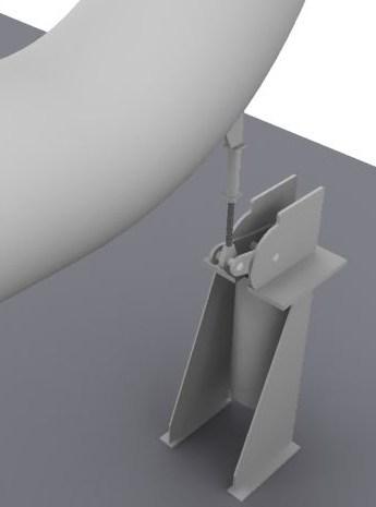
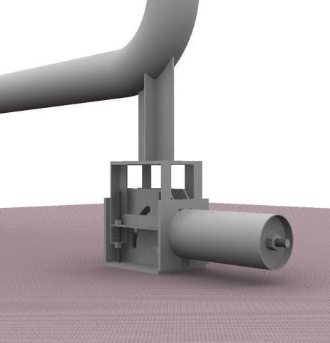
27 AAA Technology & Specialties Co., Inc. Page 26 U TYPE UPTHRUST The Upthrust support is designed for use when the pipe must be supported from below and when there is room to extend the casing horizontally. The Type U EQUALBALANCE Upthrust support may be attached to the supporting structure or foundation, by either bolting or welding. Generally, a low friction slide bearing is supplied on the top of the load table so that the member being supported by the Upthrust support can move laterally with minimal resistance. Vertical alignment of the load table is maintained by PTFE slide bearings during support movement. The Type U EQUALBALANCE Upthrust support is available for loads from 34 lbs through 20,117 lbs and total travels from 1 ½ through 12 inches. TOTAL TRAVEL B MAX. D E F G H J K / / / /4 3 11/16 8 9/ / /2 4 1/4 10 9/ / /4 33 3/8 16 1/2 4 5/ / / / /4 35 1/ /2 5 1/ / /8 24 5/8 6 1/ / / / / / / /8 30 1/ /2 1 1/ / /16 7 3/8 19 7/8 1 1/8 15 1/ / /8 34 7/8 7 7/8 20 1/4 1 1/ /2 L M N P Q X Y APPROX. WEIGHT NET /8 2 3/8 1 3/8 13/16 3/8 1/4 1/ /4 1 5/8 1 7/16 1/2 3/ /4 4 1/4 1 13/16 1 1/2 3/4 5/8 3/ /2 4 1/2 2 1/16 1 1/2 3/4 3/4 3/ /8 4 5/8 2 1/2 1 1/8 1 3/16 3/ / / /2 1 13/16 3 3/16 2 1/ /4 1 1/ /2 3 9/16 3 7/16 2 1/4 1 1/4 1 1/4 1 1/ /2 3 3/8 3 5/8 2 1/4 1 1/4 1 1/4 1 1/4 1560
OWNER'S MANUAL. Copyright 2003 GAMMA - All Rights Reserved
 OWNER'S MANUAL AL Issue 1 - December 2003 Copyright 2003 GAMMA - All Rights Reserved OWNER'S MANUAL TABLE OF CONTENTS PAGE 1... WARRANTY PAGE 2... ASSEMBLY INSTRUCTIONS PAGE 4... MOUNTING THE RACQUET PAGE
600 / 600FC OWNER'S MANUAL
 PROGRESSION 600 / 600FC OWNER'S MANUAL Issue 2 / Version E - Dec. 10, 1997 Copyright 1997 GAMMA Sports - All Rights Reserved PROGRESSION 600 / 600FC OWNER'S MANUAL TABLE OF CONTENTS PAGE 1... WARRANTY
OWNER'S MANUAL. Copyright 1999 ATS - All Rights Reserved
 OWNER'S MANUAL AL Issue 2 - August 19, 1999 Copyright 1999 ATS - All Rights Reserved OWNER'S MANUAL TABLE OF CONTENTS PAGE 1... WARRANTY PAGE 2... ASSEMBLY INSTRUCTIONS PAGE 4... MOUNTING THE RACQUET PAGE
Installation, Operating, Inspection and Maintenance Instructions Ladder Climber s Safety System. Warning
 OWNER'S MANUAL Installation, Operating, Inspection and Maintenance Instructions Ladder Climber s Safety System Model # s: 6000, 6001, 6010 Warning You must read and fully understand all instructions, or
602 STRINGING MACHINE OWNER'S MANUAL
 PROGRESSION 602 STRINGING MACHINE OWNER'S MANUAL AL Issue 1- April 2000 Copyright 2000 GAMMA Sports - All Rights Reserved PROGRESSION 602 STRINGING MACHINE TABLE OF CONTENTS PAGE 1... WARRANTY PAGE 2...
OPERATIONS/PARTS MANUAL FOR PATTERSON'S WWP40M-12 and all WIDE DRUM variations of this HAND OPERATED WINCH.
 W. W. Patterson Company 3 Riversea Road Pittsburgh, PA 15233 Phone: 800-322-2018 FAX: 412-322-2785 OPERATIONS/PARTS MANUAL FOR PATTERSON'S WWP40M-12 and all WIDE DRUM variations of this HAND OPERATED WINCH.
1.0 - OPENING AND CLOSING THE DOOR
 The purpose of this manual is to provide the user with instructions on how to safely open and close, how to conduct routine maintenance, and how to install the PEI TWINLOCK Closure on a pressure vessel.
310 SERIES TILT-TO-LOAD ROTATOR. The Specialist In Drum Handling Equipment
 OPERATOR S MANUAL FOR MORSE TILT-TO-LOAD DRUM ROTATOR SAFETY INFORMATION: While Morse Manufacturing Co. drum handling equipment is engineered for safety and efficiency, a high degree of responsibility
Index Table. Model 794. Installation, Operating and Maintenance Instructions
 CLOCKWISE MANUAL MAKING INTO CCW TABLE Index Table Model 794 Installation, Operating and Maintenance Instructions Black & Webster Products Division 545 Hupp Ave. P.O. Box 831, Jackson, Michigan 49204 2009
O P E R ATING INSTRUCTIONS FOR MODEL SPR-45 Automatic Screen and Stencil Printer
 O P E R ATING INSTRUCTIONS FOR MODEL SPR-45 Automatic Screen and Stencil Printer TABLE OF CONTENTS I. SPECIFICATIONS...3. II. SAFETY INSTRUCTIONS...4. III. INSTALLATION...5. IV. SET-UP...6. V. SYSTEM OPERATION...9.
Series 8500 Expansion Compensators. Catalog 674H
 Series 8500 Expansion Compensators Catalog 674H 500 Laminated Bellows Expansion J Series 8500 on Joints Expansion Compensators Sizes 3/4" through 4" Threaded, welded, flanged and grooved steel pipe joints
FRONT BOLT ACTION ASSAULT SHOTGUN
 SPECIFICATIONS: CATEGORY........... IMPROVISED; NOTE: CAN BE MANUFACTURED COMMERCIALLY CALIBRE............ 410 TO 12 GAUGE; ADAPTABLE CAPACITY............... 8 TO 10 ROUNDS,.410 CAL. OPERATION..........
OPERATIONS/PARTS MANUAL FOR PATTERSON'S MODEL # WWP40M-LPS-6 LOW-PROFILE BARGE CONNECTOR WINCH
 W. W. Patterson Company 3 Riversea Road Pittsburgh, PA 15233 Phone: 800-322-2018 FAX: 412-322-2785 OPERATIONS/PARTS MANUAL FOR PATTERSON'S MODEL # WWP40M-LPS-6 LOW-PROFILE BARGE CONNECTOR WINCH Please
Marine 6-Boat Free-Standing Racks SKU: Updated November 2011
 Marine 6-Boat Free-Standing Racks SKU: 30-061 Updated November 011 Contains: Marine -Boat Free-Standing Racks (SKU 1-003) Marine 3 rd Boat Expansion Racks (SKU 1-0303) Marine Back Legs (SKU -001) 3 Sets
OP CHECKLIST FOR 1D CONSOLIDATION LABORATORY TEST
 Page 1 of 5 WORK INSTRUCTIONS FOR ENGINEERS NHB Compiled by : LSS Checked by : GSS Approved by : OP-3-31. CHECKLIST FOR 1D CONSOLIDATION LABORATORY TEST Page 2 of 5 31.0 CHECKLIST ITEMS *(refer to respective
CLEANROOM GEL GRID CEILING SYSTEM PRODUCT DATA Division
 5023 HAZEL JONES ROAD, BOSSIER CITY, LA 71111 888.315.1561 800.877.8746 FAX SALES@GORDONCLEANROOM.COM GORDONCLEANROOM.COM AN EMPLOYEE OWNED COMPANY CLEANROOM GEL GRID CEILING SYSTEM PRODUCT DATA Division
Horizontal Bladder Tanks
 DATA SHEET Horizontal Bladder Tanks Features UL Listed and FM Approved for use with various ANSUL proportioners and foam concentrates 175 psi (12.1 bar) maximum allowable working pressure (design pressure)
MASTER TRUING STAND TS-3. Optional Dial indicator set with brackets Dial indicator bracket set only
 MASTER TRUING STAND TS-3 3 2 1 3 8 9 4 10 7 6 5 12 13 Optional 1555-1 Dial indicator set with brackets 1556-1 Dial indicator bracket set only 49 11 16 14 15 48 32 31 37 38 20 19 17 18 34 39 21 36 22 33
BRONZE BUSHING REPLACEMENT PROCEDURE DN345 & NL450C
 1 BRONZE BUSHING REPLACEMENT PROCEDURE V.2 12/3/2014 DN345 & NL450C 2 Safety Instructions Removing Walking Beams 3 1. Position spreader on a flat concrete surface capable of supporting weight of spreader
IMPORTANT: RECEIVING INSTRUCTIONS:
 Instruction Sheet Sidewinder Mechanical Bender IMPORTANT: RECEIVING INSTRUCTIONS: Visually inspect all components for shipping damage. If any shipping damage is found, notify carrier at once.shipping damage
MODEL 200 KNIFE GATE VALVES INSTALLATION & MAINTENANCE MANUAL
 MODEL 200 KNIFE GATE VALVES INSTALLATION & MAINTENANCE MANUAL Index 1. List of components / General arrangement 2. Description 3. Handling 4. Installation 5. Actuators / Operation 6. Maintenance a. Changing
Vertical Bladder Tanks
 DATA SHEET Vertical Bladder Tanks Features UL Listed and FM Approved for use with various ANSUL proportioners and foam concentrates 175 psi (12.1 bar) maximum allowable working pressure (design pressure)
Sprocket Selection Guidelines
 Sprocket Selection Guidelines Table 1 Information Necessary to Order Sprockets 1. Chain Size Number, type, or drawing number of the chain to be used on the sprocket. (The suitability of a sprocket depends
Serving. Petrochemicals Power Semiconductor Waste Treatment Oil & Gas Transmission Lines Bulk Gas Plants
 Serving Petrochemicals Power Semiconductor Waste Treatment Oil & Gas Transmission Lines ulk Gas Plants Mining & Metals Pharmaceuticals Pulp & Paper Mills Sugar Mills Nuclear Desalinization Plants NOTES:
200 STRINGING MACHINE
 200 STRINGING MACHINE OWNER S MANUAL Issue 1 - July 2010 Provided by www.gssalliance.com 200 OWNER S MANUAL TABLE OF CONTENTS WARRANTY...PAGE 2 FEATURES...PAGE 3 ASSEMBLY INSTRUCTIONS...PAGE 4 MOUNTING
Threaded Closures Installation, Operation & Maintenance
 Howard Street Bulletin TT Louisville, KY 0 USA Revised Jan 0 Phone 0--0 Fax 0--00 Threaded Closures Installation, Operation & Maintenance Caution: Operating a closure can be a hazardous activity and certain
WHEATLEY Series 500 Swing Check Valve
 Document Number: TC003001-13 Revision: 02 WHEATLEY Series 500 Swing Check Valve Installation, Operation, and Maintenance Manual TABLE OF CONTENTS BILL OF MATERIALS...3 SCOPE...5 INSTALLATION AND OPERATION
Typical Piping Layouts for PREMIX Blower Mixer Systems
 PREMIX Blower s Page 3103 Block & Bleed system is frequently required by insurance authorities. Typical Piping Layouts for PREMIX Blower Systems Maxon assumes no responsibility for the use or misuse of
WHEATLEY WHEATLEY SERIES 500 SWING CHECK VALVE. Installation, Operation and Maintenance Manual
 WHEATLEY SERIES 500 SWING CHECK VALVE STANDARD INTEGRAL SEAT & OPTIONAL REMOVABLE SEAT 2" FP - 6" FP 150# - 1500# 8" FP - 12" FP 150# - 900# API 6D and B16.34 2" FP - 4" FP 5000# DRILLING PRODUCTION VALVE
Certified Accuracy. Ring Force Gauge. Models and Capacities Available. Design and Principle of Operation
 Certified Accuracy Ring Force Gauge The accurate measurement of mechanical forces is required in hundreds of applications from a simple weighing procedure to the calibration of testing machines and load
DM-RARD (English) Dealer's Manual. ROAD MTB Trekking. City Touring/ Comfort Bike. Rear Derailleur DURA-ACE RD-R9100 ULTEGRA RD-R8000
 Dealer's Manual. ROAD MTB Trekking. City Touring/ Comfort Bike. Rear Derailleur DURA-ACE RD-R9100 ULTEGRA RD-R8000") (English) DM-RARD001-03 Dealer's Manual ROAD MTB Trekking City Touring/ Comfort Bike URBAN SPORT E-BIKE Rear Derailleur DURA-ACE RD-R9100 ULTEGRA RD-R8000 CONTENTS IMPORTANT NOTICE... 3 TO ENSURE SAFETY...
(English) DM-RARD001-03 Dealer's Manual ROAD MTB Trekking City Touring/ Comfort Bike URBAN SPORT E-BIKE Rear Derailleur DURA-ACE RD-R9100 ULTEGRA RD-R8000 CONTENTS IMPORTANT NOTICE... 3 TO ENSURE SAFETY...
FIRST TEAM SPORTS, INC Storm Portable Series Assembly Instructions
 FIRST TEAM SPORTS, INC Storm Portable Series Assembly Instructions WARNING! WARNING! WARNING! THIS BASKETBALL SYSTEM IS SPRING LOADED AND SHIPPED UNDER TENSION. ATTEMPTING TO ASSEMBLE OR DISASSEMBLE ANY
Model MTB-ASME Vertical Bladder Tanks
 DATA SHEET Model MTB-ASME Vertical Bladder Tanks Features n UL Listed for use with various proportioners and foam concentrates n 175 psi (12.1 bar) maximum allowable working pressure (design pressure)
Model MTB-ASME Horizontal Bladder Tanks
 DATA SHEET Model MTB-ASME Horizontal Bladder Tanks Features n UL Listed and FM Approved for use with various proportioners and foam concentrates n 175 psi (12.1 bar) maximum allowable working pressure
KTM OM-2 SPLIT BODY FLOATING BALL VALVES INSTALLATION AND MAINTENANCE INSTRUCTIONS
 Before installation these instructions must be fully read and understood SECTION 1 - STORAGE 1.1 Preparation and preservation for storage All valves should be properly packed in order to protect the parts
PUSH PIER SYSTEMS STABILITY. SECURITY. INTEGRITY. Push Pier Systems PN #MBPPT
 PUSH PIER SYSTEMS STABILITY. SECURITY. INTEGRITY. PN #MBPPT Push Pier Systems About Foundation Supportworks is a network of the most experienced and knowledgeable foundation repair and new construction
DM-MBRD (English) Dealer's Manual. ROAD MTB Trekking. City Touring/ Comfort Bike. Rear Derailleur SLX RD-M7000 DEORE RD-M6000
 Dealer's Manual. ROAD MTB Trekking. City Touring/ Comfort Bike. Rear Derailleur SLX RD-M7000 DEORE RD-M6000") (English) DM-MBRD001-04 Dealer's Manual ROAD MTB Trekking City Touring/ Comfort Bike URBAN SPORT E-BIKE Rear Derailleur SLX RD-M7000 DEORE RD-M6000 CONTENTS IMPORTANT NOTICE... 3 TO ENSURE SAFETY... 4
(English) DM-MBRD001-04 Dealer's Manual ROAD MTB Trekking City Touring/ Comfort Bike URBAN SPORT E-BIKE Rear Derailleur SLX RD-M7000 DEORE RD-M6000 CONTENTS IMPORTANT NOTICE... 3 TO ENSURE SAFETY... 4
Model MTB-ASME Vertical Bladder Tanks
 DATA SHEET Model MTB-ASME Vertical Bladder Tanks Features n UL Listed for use with various proportioners and foam concentrates n 175 psi (12.1 bar) maximum allowable working pressure (design pressure)
Only. Gives You the TechLock. System Advantage ASSEMBLY, DISASSEMBLY AND TROUBLESHOOTING INSTRUCTIONS FOR 3000 SERIES FONTAINE
 April 00 Only Gives You the TechLock System Advantage ASSEMBLY, DISASSEMBLY AND TROUBLESHOOTING INSTRUCTIONS FOR 000 SERIES FONTAINE C o n n e c t y o u r b u s i n e s s w i t h F O N T A I N E April
INSTRUCTIONS 360 Y-DROP HAGIE STS 2015
 INSTRUCTIONS 60 Y-DROP HAGIE STS 05 INSTRUCTIONS 60 Y-DROP HAGIE STS 05 INTRODUCTION Before beginning, it s important to know where each mounting bracket fits relative to the row spacing involved. The
! WARNING. Model PFC-1-G (direct acting) PFC-1-GR (reverse acting) Modulating Pneumatic Liquid Level Controls INSTRUCTION MANUAL MM-110B
 PFC-1-GR (reverse acting) Modulating Pneumatic Liquid Level Controls INSTRUCTION MANUAL MM-110B") INSTRUCTION MANUAL MM-110B Model PFC-1-G (direct acting) PFC-1-GR (reverse acting) Modulating Pneumatic Liquid Level Controls APPLICATIONS: Use with other pneumatic devices, for liquid level sensing in
INSTRUCTION MANUAL MM-110B Model PFC-1-G (direct acting) PFC-1-GR (reverse acting) Modulating Pneumatic Liquid Level Controls APPLICATIONS: Use with other pneumatic devices, for liquid level sensing in
VERSA BIKE RACK INSTRUCTIONS
 VERSA BIKE RACK INSTRUCTIONS Models #8, 8 Important This rack is designed for use with a or. receiver hitch. The rack is designed to hold a maximum of two bicycles. Do not use it for anything other than
MODEL WEIGH MODULE
 MODEL 65082 WEIGH MODULE INSTALLATION & OPERATING MANUAL P.O. Box 775 - Farmington, NH 03835 Tel: 603-755-3885 email: cands_nh@msn.com www.candscontrols.com Model 65023 Cantilever Beam Transducer Nickel-Plated
Window Replacement Hardware
 Casement and Awning Tracks Hand 750-1361414 Shown 750-1361415 Opposite 38-53 Steel 38-53CG CoastGard 38-55 Steel 38-55SS Stainless Steel 38-59 Steel 38-65 Steel 38-54 Aluminum Dorchester 38-51ST Dorchester
OPERATIONS/PARTS MANUAL FOR PATTERSON'S WWP50-H-14 HYDRAULIC WINCH.
 W. W. Patterson Company 3 Riversea Road Pittsburgh, PA 15233 Phone: 800-322-2018 FAX: 412-322-2785 OPERATIONS/PARTS MANUAL FOR PATTERSON'S WWP50-H-14 HYDRAULIC WINCH. Please fill in the following blanks
BEAMGUARD SAFETY POST TM INSTRUCTIONS
 BEAMGUARD SAFETY POST TM INSTRUCTIONS READ THESE WARNINGS BEFORE USING THE BEAMGUARD SAFETY POST! 1. Before use of this system, read and understand all instructions, warnings, cautions and notes marked
Vertical and Horizontal Bladder Tanks
 DATA SHEET Vertical and Horizontal Tanks Application The ANSUL bladder tank is one component in a balanced pressure proportioning system. Its operation requires no external power other than a pressurized
Fairlane & Meteor Instruction Package RC-114K. Rear Coilover Suspension Kit NOTE...
 ROD & CUSTOM Motorsports INCORPORATED 1962-1965 Fairlane & Meteor Instruction Package RC-114K Rear Coilover Suspension Kit NOTE... PLEASE READ ALL INSTRUCTIONS INCLUDED WITHIN THIS PACKAGE. IF AFTER READING
Air Operated Hydraulic Pumping Systems to 50,000 psi
 High Pressure Equipment Air Operated Hydraulic Pumping Systems to 50,000 psi PS-10: 10,000 psi PS-20: 20,000 psi PS-30: 30,000 psi PS-40: 40,000 psi PS-50: 50,000 psi PS-90: 90,000 psi High Pressure air
ACCUMULATOR OPERATING & MAINTENANCE INSTRUCTIONS
 ACCUMULATOR OPERATING & MAINTENANCE INSTRUCTIONS READ ALL INSTRUCTIONS PRIOR TO INSTALLATION AND OPERATION TO AVOID POSSIBLE INJURY Warning: Always consider any accumulator to contain pressure until proven
Model Copyright 2012 by General Machine Products (KT), LLC
, LLC") LIGHTWEIGHT CAPSTAN WINCH OPERATION & MAINTENANCE MANUAL Model 70627 Copyright 2012 by All rights reserved. No part of this publication may be copied, reproduced or transmitted in any form whatsoever without
LIGHTWEIGHT CAPSTAN WINCH OPERATION & MAINTENANCE MANUAL Model 70627 Copyright 2012 by All rights reserved. No part of this publication may be copied, reproduced or transmitted in any form whatsoever without
OPERATIONS/PARTS MANUAL FOR PATTERSON'S WWP75H-10 HYDRAULIC WINCH.
 W. W. Patterson Company 3 Riversea Road Pittsburgh, PA 15233 Phone: 800-322-2018 FAX: 412-322-2785 OPERATIONS/PARTS MANUAL FOR PATTERSON'S WWP75H-10 HYDRAULIC WINCH. Please fill in the following blanks
SECTION BUTTERFLY VALVES
 SECTION 15112 BUTTERFLY VALVES PART 1 GENERAL 1.01 SUMMARY A. All butterfly valves shall be of the tight closing, rubber seated type and fully comply with the latest revision of AWWA Standard C504, Class
BARRIER OFFSET 0" A 6" 6" A 12" 12" A 26" A 26" 3A OR 4A L OR S * ** L OR S L OR S
 ACCEPTABLE (TCB) TYPES AND ANCHORING DETAILS BASED ON UNDERLYING SURFACE TYPE AND BARRIER OFFSET FROM DROP-OFF BARRIER OFFSET UNDERLYING SURFACE 0" A 6" 6" A 12" 12" A 26" A 26" TCB TYPE DETAIL TCB TYPE
IMPORTANT: If you have questions on the use, care, or suitability of this equipment for your application, contact DBI/SALA.
 User Instruction Manual Precast Concrete Beam Horizontal Lifeline System This manual is provided as the Manufacturer s Instructions, and should be used as part of an employee training program as required
OWNERS MANUAL. Model Shown with optional Primary Mooring Cleats. Portable Mooring System SAFETY OPERATION MAINTENANCE PARTS
 OWNERS MANUAL Model 2400 Shown with optional Primary Mooring Cleats. Portable Mooring System SAFETY OPERATION MAINTENANCE PARTS CAUTION: Before using your new Pier Tender, read rules for Safety, Operation,
Safety System Installation Guide for ARE Wind Poles
 Safety System Installation Guide for ARE Wind Poles V. 1 May 2011 ** Climbing pegs and ladder should be installed before the pole is erected.** A. Install climbing pegs Install climbing pegs (bolt set)
CLASS CYCLE P8000 OWNER'S MANUAL JOHNSON HEALTH TECH. CO., LTD.
 CLASS CYCLE P8000 JOHNSON HEALTH TECH. CO., LTD. No.26, Ching Chuan Rd., Taya Hsiang, Taichung Hsien 428, Taiwan, R.O.C. TEL: +886-4-2566700 FAX: +886-4-2560087 E-mail: sales@johnsonfitness.com http://www.johnsonfitness.com
Method of Test for Flat & Elongated Particles
 Method of Test for Flat & Elongated Particles 1. Scope: This test is for determining the percentage by weight of coarse aggregate that have a maximum to minimum dimension greater than the specified ratio
Installation Instructions for the AlphaDeck Staging System
 Installation Instructions for the AlphaDeck Staging System Step 1 - Preparation A. Before setting up this system, determine the location of the stages and all the parts you will need. B. Read through the
BUTTERFLY VALVES Series 800
 BUTTERFLY VALVES Series 800 WARNING Before proceeding read ALL instructions and become familiar with the equipment and associated drawings. Follow ALL applicable safety regulations and codes for pressurized
X-6FC STRINGING MACHINE OWNER'S MANUAL. Issue 1 - May Copyright 2004 GAMMA Sports - All Rights Reserved
 X-6FC STRINGING MACHINE OWNER'S MANUAL Issue 1 - May 2004 Copyright 2004 GAMMA Sports - All Rights Reserved OWNER'S MANUAL GAMMA X-6FC TABLE OF CONTENTS PAGE 1... WARRANTY PAGE 2... FEATURES PAGE 3...
Structural Design of Tank Weighing Systems
 Structural Design of Tank Weighing Systems 1. Initial observations Some essential rules must be followed when installing load cells in tanks. For example, tanks are frequently subject to weather conditions
Torque Specifications
 SENR3130-10 Torque Specifications All Caterpillar Products S/N From the library of Barrington Diesel Club CONTENT General Information 01/07/2005 Introduction to Torque 01/07/2005 Torque-Turn 01/07/2005
AWWA C504 COMPLIANT VALVES FROM 3 THRU 108
 AWWA C504 COMPLIANT VALVES FROM 3 THRU 108 PO Box 411 Berwick PA 18603 800-247-VALV www.crispinvalve.com 500 SERIES: Sizes 3-20 Available The K-Flo 500 Series is a heavy-duty resilient seated butterfly
Banyan Air Service November 18, 2011 AVE Aviation and Commerce Center Building 1 Miami, FL
 SECTION 10801 - TOILET AND BATH ACCESSORIES PART 1 - GENERAL 1.1 RELATED DOCUMENTS A. Drawings and general provisions of the Contract, including General and Supplementary Conditions apply to this Section.
Parts & Installation Instructions SV & SV 2 8.5, 9.5 & 10.5 and SVLD 7.5 Snow Plow
 Form -0 R September 0 Parts & Installation Instructions SV & SV.,. &. and SVLD. Snow Plow Item Part No. Part No. Part No. Part No. Part No. Part No. Qty. Description SVLD. SV. SV. SV. SV. SV. Moldboard
WINSAFE Corp. Operating Instructions For Outrigger Davit. Winsafe Part # WSOR208
 WINSAFE Corp. Operating Instructions For Outrigger Davit Winsafe Part # WSOR208 These instructions must be read and understood by anyone installing or suspending equipment from Winsafe modular beams and
BC Shackle. Made in the China. Alloy Steel Anchor Shackle. Instructions for handling and use - Please read in full before using this device
 BC Shackle Made in the China Alloy Steel Anchor Shackle Instructions for handling and use - Please read in full before using this device Index 1.) Introduction 2.) Warnings / General Use Guidelines 3.)
MAGNETIC INDOOR CYCLING BIKE
 MAGNETIC INDOOR CYCLING BIKE SF-B1805 USER MANUAL IMPORTANT! Please retain owner s manual for maintenance and adjustment instructions. Your satisfaction is very important to us, PLEASE DO NOT RETURN UNTIL
DIRECT DRIVE DIXIE DOUBLE SEAMER Model 25D
 OPERATOR'S MANUAL DIRECT DRIVE DIXIE DOUBLE SEAMER Model 25D LUBRICATE DAILY: A. Gears inside gear housing at chuck shaft (1) Oil B. Seam rolls and cam rolls (4) - Oil C. Seam roll levers through gear
Ford Service Saddles and Tapping Sleeves
 Section AA 5/2001 Ford Service Saddles and Tapping Sleeves The Ford Meter Box Co., Inc. 775 Manchester Avenue, P.O. Box 443, Wabash, Indiana, USA 46992-0443 Telephone: 219/563-3171 FAX: 1-800-826-3487
Operating Procedures for GripTight 15.5 SDR & IPS Test Plugs
 EST Group DC2518 08/01 REV 3 12/12 Page 1 of 6 Operating Procedures for GripTight SDR & IPS Test Plugs WARNING For proper operation, GripTight plugs must be assembled as shown in Figure 1. Pressure testing
OPERATIONS/PARTS MANUAL FOR PATTERSON'S HAND OPERATED WINCH
 DOC # 5071-A W. W. Patterson Company 3 Riversea Road Pittsburgh, PA 15233 Phone: 800-322-2018 FAX: 412-322-2785 OPERATIONS/PARTS MANUAL FOR PATTERSON'S HAND OPERATED WINCH Please fill in the following
HEAVY DUTY PNEUMATIC
 HEAVY DUTY PNEUMATIC Series A4 MEDIUM DUTY HYDRAULIC Series H4 PERMANENTLY LUBRICATED HEAVY DUTY PNEUMATIC Series L4 586.778.7680 SERIES A4/L4/H4 39 A4/L4/H4 FEATURES 1 1 9 9 12 8 7 5 12 3 13 4 10 2 11
USER S INSTRUCTION MANUAL FOR THE INSTALLATION, OPERATION & MAINTENANCE OF THE GUARDIAN TEMPORARY HORIZONTAL LIFELINE SYSTEM
 USER S INSTRUCTION MANUAL FOR THE INSTALLATION, OPERATION & MAINTENANCE OF THE GUARDIAN 04630 TEMPORARY HORIZONTAL LIFELINE SYSTEM 1 WARNING This is a design compatible component for a comprehensive Guardian
Figure 1 - Parts Identification
 Instructions for the following series products: Zorbit Energy Absorber Kits (See back page for specific model numbers.) User Instruction Manual Zorbit Energy Absorber Kits for Horizontal Lifeline Systems
DM-MARD (English) Dealer's Manual. ROAD MTB Trekking. City Touring/ Comfort Bike REAR DERAILLEUR XTR RD-M9100 RD-M9120
 Dealer's Manual. ROAD MTB Trekking. City Touring/ Comfort Bike REAR DERAILLEUR XTR RD-M9100 RD-M9120") (English) DM-MARD001-00 Dealer's Manual ROAD MTB Trekking City Touring/ Comfort Bike URBAN SPORT E-BIKE REAR DERAILLEUR XTR RD-M9100 RD-M9120 CONTENTS CONTENTS...2 IMPORTANT NOTICE...3 TO ENSURE SAFETY...4
(English) DM-MARD001-00 Dealer's Manual ROAD MTB Trekking City Touring/ Comfort Bike URBAN SPORT E-BIKE REAR DERAILLEUR XTR RD-M9100 RD-M9120 CONTENTS CONTENTS...2 IMPORTANT NOTICE...3 TO ENSURE SAFETY...4
807 E. Parkridge Ave. Corona, CA ACCU Fax:
 807 E. Parkridge Ave. Corona, CA 92879 1-888-ACCU-372 951-479-0909 Fax: 951-479-0305 www.accuratefishing.com O WNER S WNER S M ANUAL CONTENTS Features 1 Getting Acquainted 2 Operation 3 2-Speed Function
Fontaine Fifth Wheel Ultra LT Rebuild Procedures
 Fontaine Fifth Wheel Ultra LT Rebuild Procedures Disassembly Assembly Adjustments 800-874-9780 2010 LT-147 January 2010 Dissassembly Cover plate removed for clarity. Refer to exploded view of assembly
BELT DRIVE INDOOR CYCLING BIKE SF-B1712 USER MANUAL
 BELT DRIVE INDOOR CYCLING BIKE SF-B1712 USER MANUAL IMPORTANT! Please retain owner s manual for maintenance and adjustment instructions. Your satisfaction is very important to us, PLEASE DO NOT RETURN
X-6 STRINGING MACHINE OWNER'S MANUAL. Issue 1 - May Copyright 2004 GAMMA Sports - All Rights Reserved
 X-6 STRINGING MACHINE OWNER'S MANUAL Issue 1 - May 2004 Copyright 2004 GAMMA Sports - All Rights Reserved OWNER'S MANUAL GAMMA X-6 TABLE OF CONTENTS PAGE 1... WARRANTY PAGE 2... FEATURES PAGE 3...ASSEMBLY
OWNER S MANUAL. This manual contains; IMPORTANT SAFETY INFORMATION INSTALLATION INSTRUCTIONS MAINTENANCE FACTORY SERVICE REPAIR PARTS WARRANTY
 OWNER S MANUAL This manual contains; IMPORTANT SAFETY INFORMATION INSTALLATION INSTRUCTIONS MAINTENANCE FACTORY SERVICE REPAIR PARTS WARRANTY Models covered; PA506 EL506 Ergonomic Tool Arms, LLC PO Box
ROTATING DISK VALVES INSTALLATION AND MAINTENANCE 1. SCOPE 3 2. INFORMATION ON USAGE 3 3. VALVE TYPES 3 4. OPERATORS 5 5. VALVE CONSTRUCTION 6
 Sub Section INDEX Page Number 1. SCOPE 3 2. INFORMATION ON USAGE 3 3. VALVE TYPES 3 4. OPERATORS 5 5. VALVE CONSTRUCTION 6 6. INSTALLATION AND OPERATION 6 7. MAINTENANCE 8 8. REPAIR 9 9. ASSEMBLY 10 10.
PUNE TECHTROL PVT LTD. Instruction and Maintenance Manual for Float and Tape Gauge FTG
 PUNE TECHTROL PVT LTD Instruction and Maintenance Manual for and Tape Gauge FTG INSTALLATION, OPERATION AND MAINTENANCE MANUAL FOR FLOAT AND TAPE GAUGE FTG 1 Introduction : It is used to measure and indicate
Ground Release Shackle
 Operator Manual Subhead Advantages: In the process of installing Slide Rail, the shackle connecting the top of posts, panels, and sheeting must be removed manually. This is normally done by climbing on
NOVALYNX CORPORATION MODEL RAIN GAUGE CALIBRATOR INSTRUCTION MANUAL
 NOVALYNX CORPORATION MODEL 260-2595 RAIN GAUGE CALIBRATOR INSTRUCTION MANUAL REVISION DATE: August 2018 Receiving and Unpacking Carefully unpack all components and compare to the packing list. Notify NovaLynx
FLANGED TWO-PIECE BALL VALVES
 INTRODUCTION This instruction manual includes installation, operation, and maintenance information for FNW flanged split-body ball valves. This manual addresses lever operated ball valves only. Please
VL 2K LIFT D-L WINCH INSTRUCTIONS (Applies to P/Ns , , , , , )
") VL 2K LIFT D-L WINCH INSTRUCTIONS (Applies to P/Ns 3714022, 3714028, 3714034, 3714040, 3714043, 3714046) REIMANN & GEORGER CORPORATION MARINE PRODUCTS BUFFALO, NY P/N 6112103 04/09/18 1 SAFETY 1.1 INTRODUCTION
VL 2K LIFT D-L WINCH INSTRUCTIONS (Applies to P/Ns 3714022, 3714028, 3714034, 3714040, 3714043, 3714046) REIMANN & GEORGER CORPORATION MARINE PRODUCTS BUFFALO, NY P/N 6112103 04/09/18 1 SAFETY 1.1 INTRODUCTION
Repair instructions. Pivot bushing replacement. XL-AS10001RM-en-DE Rev B
 Repair instructions Pivot bushing replacement XL-AS10001RM-en-DE Rev B Table of contents Table of contents 1 General information... 3 1.1 Safety information...3 1.2 Legal information...4 1.3 Order and
OWNER'S MANUAL. Turnbuckle. Stanchions. Warning
 GEMTOR, INC....when your life is on the line One Johnson Avenue Matawan, NJ 07747 732-583-6200 800-405-9048 Fax 732-290-9391 OWNER'S MANUAL Installation, Operating, Inspection and Maintenance Instructions
Powers Controls D Day-Night Thermostats
 Powers Controls D Day-Night Thermostats Technical Instructions Document No. 155-073P25 TH 832-2 Description The D Day-Night or Two Temperature Thermostat is available as a room-type instrument. It is essentially
Model: 5100 OmniSteel Volleyball System
 Model: 5100 OmniSteel Volleyball System Installation, Operation and Maintenance Instructions Please read all instructions before attempting installation or operation of these units SAVE THESE INSTRUCTIONS
TOWER INSPECTION REPORT
 3010 S. Hwy 77, Suite 600 Waxahachie, Texas 75165 http://ctctower.com Office: 972/923-9504 Fax: 972/923-9619 TOWER INSPECTION REPORT PREPARED FOR MR. CUSTOMER 1,563 GUYED TOWER NEAR CITY, STATE JANUARY
DBML-60/80 Squeeze Tool
 DBML-60/80 Squeeze Tool OPERATORS MANUAL Description The Mustang Model DBML-60/80 Hydraulic squeeze tool has been manufactured since 1995. A Mustang 3 3/4 bore doubleacting cylinder producing 41,000 lbs
DM-RD (English) Dealer s Manual. ROAD Rear Derailleur RD-9000 RD-6800 RD-5800 RD-4700
 Dealer s Manual. ROAD Rear Derailleur RD-9000 RD-6800 RD-5800 RD-4700") (English) DM-RD0003-09 ROAD Rear Derailleur Dealer s Manual RD-9000 RD-6800 RD-5800 RD-4700 CONTENTS IMPORTANT NOTICE...3 TO ENSURE SAFETY...4 LIST OF TOOLS TO BE USED...6 INSTALLATION...8 Chain length...
(English) DM-RD0003-09 ROAD Rear Derailleur Dealer s Manual RD-9000 RD-6800 RD-5800 RD-4700 CONTENTS IMPORTANT NOTICE...3 TO ENSURE SAFETY...4 LIST OF TOOLS TO BE USED...6 INSTALLATION...8 Chain length...
Installation, Operation & Maintenance Manual
 Original Instructions Installation, Operation & Maintenance Manual Sentry VREL Control Valve Pressure Conditioning S-SW-IOM-00277-15 1-17 Table of Contents Safety Information... 3 General Safety Precautions...
North American 7337A/B/C-4 High Pressure Gas Regulators
 Combustion North American A/B/C-4 High Pressure Gas Regulators Bulletin A/B/C-4 A-4, B-4 and C-4 Regulators reduce high gas supply pressures to practical use levels. Since capacities will vary with the
Accu Max Limited Warranty
 Form #460 Rev B Phone: 69-789-6700 Fax: 69-78-840 E-mail: sales@marshallexcelsior.com www.marshallexcelsior.com NOTE: Before installing, inspect float gauge assembly for shipping damage that may affect