DETAIL SPECIFICATION CARBINE, 5.56 MILLIMETER: M4. Inactive for new design after 27 February 1997
|
|
|
- Hector Ramsey
- 5 years ago
- Views:
Transcription
1 INCH-POUND MIL DTL 70599B 15 June 2015 SUPERSEDING w/amendment 3 20 July 2012 DETAIL SPECIFICATION CARBINE, 5.56 MILLIMETER: M4 Inactive for new design after 27 February 1997 This specification is approved for use by all Departments and Agencies of the Department of Defense. 1. SCOPE 1.1 Scope. This detail specification prescribes the requirements and identifies the verification procedures for the lightweight, air-cooled, gas operated, magazine-fed, 5.56 millimeter (mm) weapon designed for either three shot automatic burst or semi-automatic fire, hereafter referred to simply as the weapon. 2. APPLICABLE DOCUMENTS 2.1 General. The documents listed in this section are specified in sections 3 and 4 of this specification. This section does not include documents cited in other sections of this specification or recommended for additional information or as examples. While every effort has been made to ensure the completeness of this list, document users are cautioned that they must meet all specified requirements of documents cited in sections 3 and 4 of this specification, whether or not they are listed. Comments, suggestions, or questions on this document should be addressed to Commander ARDEC, ATTN: RDAR-, Picatinny Arsenal, NJ or ed to ardecstdzn@conus.army.mil. Since contact information can change, you may want to verify the currency of this address information using the ASSIST Online database at AMSC N/A FSC 1005 DISTRIBUTION STATEMENT A. Approved for public release, distribution is unlimited.
2 2.2 Government documents Specifications, standards and handbooks. The following specifications, standards, and handbooks form a part of this document to the extent specified herein. Unless otherwise specified, the issues of these documents are those cited in the solicitation or contract. DEPARTMENT OF DEFENSE SPECIFICATIONS MIL-PRF Cleaning Compound Solvent (for Bore of Small Arms and Automatic Aircraft Weapons) MIL-PRF Lubricant, Cleaner and Preservative for Weapons and Weapons Systems MIL-W Weapons: Small Arms and Aircraft Armament Systems, General Specification for MIL-W Weapons and Support Material, Standard Quality Assurance Provisions for DEPARTMENT OF DEFENSE STANDARDS MIL-STD DOD Preferred Methods for Acceptance of Product (Copies of these documents are available online at or from the Standardization Documents Order Desk, 700 Robbins Avenue, Bldg 4D, Philadelphia, PA ) Other government documents, drawings and publications. The following other Government documents, drawings and publications form a part of this document to the extent specified herein. Unless otherwise specified, the issues of these documents are those cited in the solicitation or contract. ARMY TECHNICAL MANUALS TM Operator s Manual for Carbine, 5.56MM, M4 W/E ( ) (EIC:4FJ) (These TMs may be viewed and printed at U.S. ARMY ARMAMENT RESEARCH, DEVELOPMENT AND ENGINEERING CENTER (ARDEC) DRAWINGS Carbine, 5.56 MM, M Cartridge, 5.56MM, Ball, M Gage, Trigger Pull-Field Service Gage, Indicator Gage, Plug 2
3 Gage, Plug Cylinder, Pressure Computer, Rate of Fire Gage, Headspace (Min) Gage, Headspace (Max) Gage, Bore Straightness Bolt Barrel and Barrel Extension Assembly Marking, Lower Receiver Model M Cartridge, 5.56MM, Test, High Pressure, M Targeting and Accuracy Test Firing Fixture Barrel & Bolt Proof Testing Fixture Function Firing Test Stand Bolt Carrier Assembly (Copies of these drawings maybe requested online at or from US Army ARDEC, ATTN: RDAR-EIS-PE, Picatinny Arsenal, NJ ) 2.3 Non-government publications. The following documents form a part of this document to the extent specified herein. Unless otherwise specified, the issues of these documents are those cited in the solicitation or contract. AMERICAN SOCIETY FOR TESTING AND MATERIALS INTERNATIONAL (ASTM International) ASTM E Standard Practice for Magnetic Particle Examination (Copies of ASTM standards may be ordered online at or from the ASTM International, 100 Barr Harbor Drive, Conshohocken, PA ) SPORTING ARMS AND AMMUNITION MANUFACTURERS INSTITUTE STANDARD (SAAMI) ANSI/SAAMI-Z Voluntary Industry Performance Standards for Pressure and Velocity of Centerfire Rifle Sporting Ammunition for the Use of Commercial Manufacturers (Copies of SAAMI standards may be ordered online at Order of precedence. Unless otherwise noted herein or in contract, in the event of a conflict between the text of this document and the references cited herein, the text of this document takes precedence. Nothing in this document, however, supersedes applicable laws and regulations unless a specific exemption has been obtained. 3
4 3. REQUIREMENTS 3.1 First article inspection. When specified a sample (see 6.2) of the weapon shall be subjected to first article inspection in accordance with Table II and Conformance inspection. Unless otherwise specified, all weapons shall be subjected to conformance inspection in accordance with Table II and Upper receiver and lower receiver assemblies Upper receiver and lower receiver assembly retention. When the upper receiver assembly and lower receiver assembly are attached and the takedown and pivot pins are pushed to their extreme in positions, the upper receiver assembly and lower receiver assembly shall be held securely in the closed position Opening of the upper receiver and lower assembly. When the takedown pin is withdrawn to its extreme out position, the upper receiver assembly and lower receiver assembly shall not be held securely in the closed position Detachment of the upper receiver assembly from the lower receiver assembly. The upper receiver assembly shall detach from the lower receiver assembly when the pivot and takedown pins are in their extreme out positions. 3.4 Lower receiver assembly Hammer. When the hammer is released from the cocked position, it shall pivot forward to the stop position under spring action without binding (see ) Automatic sear Automatic sear motion. When the selector is placed in the BURST position, the fire control selector shall rotate the automatic sear from its neutral position to its active position (able to engage the hammer). When the selector is removed from the BURST position, the sector shall rotate the automatic sear to its neutral position (unable to engage the hammer) without binding Automatic sear action. When the fire control selector is in the "BURST" position and the hammer has been cocked by backward motion of the bolt carrier, the automatic sear shall engage and restrain the hammer until the sear is tripped by the forward motion of the bolt carrier Fire control selector Fire control selector positions. The fire control selector shall have three positions; safe, semi-automatic and burst. On the weapon, these positions shall be labeled as SAFE, SEMI, and BURST. 4
5 Fire control selector motion. When the hammer is cocked, the fire control selector shall rotate manually from one position to another without binding Fire control selector position retention. The fire control selector shall remain in place in each position by a perceptible spring detent load until manually reset. The load shall be evidenced by a tactile (see ) resistance as the selector is arriving and leaving the position. In addition an audible click shall be heard when the detent engages Fire control selector in SAFE position functioning. With the hammer cocked and the fire control selector in the SAFE position, the hammer shall not be released when the trigger is pulled. As a result the weapon shall be incapable of being fired Fire control selector in SEMI position functioning. When the selector is placed in the "SEMI" position, the selector shall allow the semi disconnect to engage the hammer, so that the weapon is capable of semi-automatic firing only (single shot with each pull of the trigger) Fire control selector in BURST position functioning. When the selector is placed in the "BURST" position, the automatic sear shall engage the hammer, so that the weapon is capable of burst firing. One, two, or three continuous shots the first time the trigger is pulled and held back. Three continuous shots on the second and each successive time the trigger is pulled and held back. One, two or three shots if the trigger is released before completion of the three shot cycle or all cartridges are expended before completion of the three shot cycle. screw Ancillary lever retention. The ancillary lever shall be securely retained by the Bolt catch Bolt catch motion. The bolt catch shall move from its recessed position, out of the bolt carrier s way, to its raised position, a position where it can retain the bolt. Movement from the raised to recessed position shall be under spring action Bolt catch retention. The bolt catch shall be securely retained on the lower receiver by the bolt catch spring pin Bolt catch passive action. When positioned manually, the bolt catch shall remain engaged and shall hold the bolt carrier in the open position. When positioned by action of the magazine follower, the bolt catch shall remain engaged and shall hold the bolt carrier in the open position Bolt catch release. When the bolt catch release is depressed (held in the "down" position by the bolt catch plunger and spring), the bolt catch shall recess and allow a retained bolt carrier to return to the battery position (see ) Magazine catch. 5
6 Magazine catch action. The magazine catch, under spring action, shall securely retain the magazine in the magazine well. An audible click shall be heard when the catch engages Magazine catch tension adjustment. The spring tension of the magazine catch shall be adjustable by depressing the magazine release button and rotating the magazine catch clockwise to tighten; counterclockwise to loosen. Spring tension shall be measured by the tactile resistance observed as the magazine overcomes the magazine catch Magazine release button Magazine release button action. When the magazine release button is depressed, it shall disengage the magazine catch from the magazine and permit removal of the magazine Magazine release button and bolt catch interaction. When the bolt is held open (rearward) by the bolt catch, and the magazine release button is depressed, the empty magazine shall be ejected by the spring tension in the magazine follower spring Disconnects Semi-disconnect Semi-disconnect motion. When the fire control selector is placed in the SEMI position, the fire control selector shall rotate the semi-disconnect from its neutral position (not engaging the hammer) to its active position (engaging the hammer). When the selector is removed from the SEMI position, the selector shall rotate the semi-disconnect back to its neutral position Semi-disconnect action. When the selector is in the SEMI position and the trigger is held back, the semi-disconnect shall engage and restrain the hammer in the cocked position until the trigger is released. When the trigger is released, the semi-disconnect shall allow the hammer to return to the normal cocked position (when the hammer is held back by only the trigger). The transfer from the semi-disconnect to the normal cocked position shall cause an audible click as the trigger engages the hammer Burst disconnect Burst disconnect motion. When the fire control selector is placed in the BURST position, the fire control selector shall rotate the burst disconnect from its neutral position (not engaging the hammer or the burst cam) to its active position (engaging in the deepest notch of the burst cam). When the selector is removed from the BURST position, the selector shall rotate the burst disconnect back to its neutral position Burst disconnect action. When the selector is in the BURST position and the trigger is held back, the burst disconnect shall engage on the burst cam. When the burst cam rotates such that the burst disconnect engages in the deepest notch of the burst cam, the burst 6
7 disconnect shall restrain the hammer in the cocked position until the trigger is released. When the trigger is released, the burst disconnect shall allow the hammer to return to the normal cocked position (when the hammer is held back by only the trigger). The transfer from the burst disconnect to the normal cocked position shall cause an audible click as the trigger engages the hammer Trigger Trigger hammer cocked position. The trigger shall hold the hammer in the cocked position until the trigger is pulled Trigger normal position upon full trigger pull. After a full trigger pull (see ), the trigger shall return to its normal forward position under spring action Trigger normal position upon partial pull. After a partial trigger pull (see ), the trigger shall return to its normal forward position under spring action Trigger guard Trigger guard motion. The trigger guard shall move from its closed position to its fully open position (resting against the pistol grip) and back without binding Trigger guard open retention. The trigger guard shall be securely retained in the open position against the pistol grip by the trigger guard spring pin Trigger guard closed retention. The trigger guard shall be securely retained in the closed position by the trigger guard spring loaded detent Pivot pin Pivot pin motion. The pivot pin shall move between its extreme in and extreme out positions without binding Pivot pin retention in extreme in position. The pivot pin shall be securely retained in the extreme in position by spring action of the detent Pivot pin retention in extreme out position. The pivot pin shall be securely retained in the extreme out position by spring action of the detent Takedown pin Takedown pin motion. The takedown pin shall move between its extreme in and extreme out positions without binding Takedown pin retention in extreme in position. The takedown pivot pin shall be securely retained in the extreme in position by spring action of the detent. 7
8 Takedown pin retention in extreme out position. The takedown pin shall be securely retained in the extreme out position by spring action of the detent Pistol grip Pistol grip retention. The pistol grip shall be securely retained on the lower receiver Pistol grip position. The pistol grip shall not interfere with operation of the selector lever Buttstock assembly Buttstock assembly retention. The release lever shall be securely retained on the buttstock assembly and subjected to continuous pressure from the locking spring. The buttstock assembly shall not rotate on the lower receiver extension. No forward or rearward motion of the buttstock relative to the lower receiver extension shall be allowed in the extended and retracted positions Buttstock assembly motion. Pressure on the release lever (rear end) towards the buttstock shall withdraw the lock pin allowing movement from one position to the other. Release of the lever when the buttstock is positioned in the extended and retracted positions shall allow the lock pin to secure the buttstock in position Buttstock assembly removal. Pulling the rear end of the release lever away from the buttstock shall allow the buttstock to slide rearward off of the lower receiver extension Buffer assembly Buffer assembly motion. The buffer assembly shall move between its retained position and its fully compressed position without binding. Movement from compressed to retained shall be under spring action Buffer assembly retention. The buffer assembly shall be securely retained in the lower receiver assembly by the spring loaded buffer retainer Buffer assembly disassembly removal. The buffer assembly shall be capable of being disassembled from the lower receiver assembly when the spring loaded buffer retainer is manually depressed. 3.5 Upper receiver assembly Barrel assembly Barrel assembly straightness. The barrel assembly shall be straight to the extent 8
9 that a cylindrical plug with a diameter of inches, and six (6) inches in length shall drop through the barrel bore, both directions, of its own weight Gas tube Gas tube retention. The gas tube shall be securely retained to the front sight assembly by the gas tube spring pin Gas tube alignment. The gas tube shall be positioned for proper alignment with the bolt carrier key. Proper alignment shall allow for the gas tube to freely move in and out of the bolt carrier key without binding Rail cover Rail cover mounting. The rail covers shall be capable of being disassembled from and assembled to the rail adapter system by applying thumb pressure to the retaining clip and sliding rail covers onto the rail adapter system until the retaining clip automatically engages. The retaining clips shall only engage with the two end recoil slots Rail cover retention. The rail covers shall be securely retained on the rail adapter system by the retaining clip Vertical pistol grip Vertical pistol grip motion. When the lock assembly is unlocked, the vertical pistol grip shall move freely along the rail adapter system without binding Vertical pistol grip retention. The vertical pistol grip shall be securely retained on the rail adapter system by the lock assembly Front sight assembly Front sight assembly retention. The front sight assembly shall be securely retained on the barrel assembly by two taper pins Front sight post retention. The front sight post shall be held in position by the spring loaded front sight detent Front sight post adjustment. The detent, when depressed, shall disengage the front sight post and allow vertical adjustment of the post. Clockwise rotation of the front sight post, as indicated by the arrow on the top of the front sight, shall lower the front sight post. When the weapon is zeroed, there shall be at least 16 additional clicks of adjustment available in a downward direction Back-up iron sight. 9
10 Back-up iron sight retention. The back-up iron sight shall be securely retained in the rearmost slot on the upper receiver using the recoil screw and the locking bar Back-up iron sight motion. The rear sight shall pivot to full vertical position under spring action when at the extreme left and extreme right windage positions Back-up iron sight windage knob position retention. The windage knob shall be held in position by the spring loaded detent Back-up iron sight windage knob motion. The windage knob shall be capable of rotating seven complete revolutions moving the rear sight from the extreme left to the extreme right without binding Back-up iron sight trajectory compensation. The rear sight shall be capable of elevating, by means of the sight cam, to compensate for trajectory for ranges from 200 meters to 600 meters Ejection port Ejection port cover motion. The ejection port cover shall operate between its closed position and its open position (resting on the lower receiver) without binding. Movement from the open to closed position shall be under spring action Ejection port cover action. The ejection port cover shall open under spring action when the bolt carrier is moved from the locked position rearward, or from the open position forward Ejection port cover retention. The cover shall be securely retained in the closed position by the cover detent Forward assist assembly Forward assist assembly motion. When depressed, the forward assist assembly shall move from its fully outward position (where the pawl is completely disengaged from the bolt carrier) to a position where the pawl engages the bolt carrier, in battery position. When released, the forward assist assembly shall return under spring action to its fully outward position Forward assist assembly action. Depressing and releasing the forward assist shall cause progressive movement of the bolt carrier assembly into the battery position Compensator alignment. The third (middle) slot shall be straight up at top dead center (TDC). TDC is defined by the front sight post. The alignment may vary as much as one half the width of the slot either direction. 10
11 Front sling swivel Front sling swivel motion. The front sling swivel shall move between its forward position, touching the barrel, to its rear position, touching the rail adapter system, without binding Front sling swivel retention. The front sling swivel shall not disassemble from the weapon because it is securely retained to the front sight assembly by the rivet Bolt carrier assembly Key and bolt carrier assembly lock. The bolt carrier and key assembly shall move through its full range of travel without binding in the upper receiver Firing pin Firing pin motion. The firing pin shall move from a recessed position, a position below the bolt face, to a maximum protrusion of inches without binding Firing pin retention. The firing pin shall be securely retained in the bolt carrier assembly by the firing pin retaining pin Firing pin protrusion. The firing pin protrusion shall be a maximum of inches and a minimum inches Firing pin plating workmanship. The chromium plating of the firing pin shall be free of nodules, flaking, stripping, anode burns and evidence of etched base steel, except as specified on the applicable drawing Charging handle retention. When the charging handle is placed in the forward position it shall engage and lock securely in the upper receiver by the charging handle release Bolt assembly Bolt assembly motion. The bolt assembly shall move through its full range of travel and lock in the battery position Bolt assembly retention. The bolt assembly shall be securely retained in the bolt carrier by the bolt cam pin Extractor Extractor motion. The extractor shall move between its rest position (no cartridge present) and its active position (cartridge present) without binding in the bolt Extractor action. The extractor shall be capable of engaging and extracting 11
12 cartridge cases from the barrel chamber when the weapon is function fired or manually operated Extractor retention. The extractor shall be securely retained in the bolt by the extractor pin Ejector Ejector motion. The ejector shall move between its raised position (no cartridge present) and its recessed position (cartridge present) without binding. Ejector movement from its recessed position to its raised position shall be under spring action Ejector action. The ejector shall eject cartridge cases completely out of the weapon when the weapon is function fired or manually operated Ejector retention. The ejector shall be securely retained in the bolt by the ejector pin Cam pin Cam pin motion. The cam pin shall move through its full range of travel in the bolt carrier without binding Cam pin retention. The cam pin shall be securely retained in the bolt assembly by the firing pin Cam pin disassembly. The cam pin shall be capable of being removed from the bolt carrier without removal of the bolt carrier key assembly Cam pin symmetry. The cam pin shall be capable of being disassembled from the bolt and bolt carrier assembly and reassembled about its vertical axis from its original position without causing binding in the assembly. 3.6 Functional characteristics Firing pin indents Firing pin indent. The weapon shall meet the requirement of the bolt action indent, muzzle down position indent and firing pin indent position Bolt action indent. When the bolt is closed and the firing mechanism is released, the firing pin indent shall not be less than inches Muzzle down position indent. When in a muzzle down position, the bolt carrier assembly shall be released from the full recoil position and the firing mechanism shall not be actuated, the firing pin indent shall not be greater than inches. 12
13 Firing pin indent location. The firing pin indent shall not be off-center more than one half the maximum diameter of the indent Firing pin protrusion. The firing pin protrusion shall not be greater than inches and shall not be less than inches Trigger pull Minimum trigger pull. The minimum trigger pull shall not be less than 5.5 pounds when checked with the burst disconnect in a deep notch of the burst cam Maximum trigger pull. The maximum trigger pull shall not be greater than 9.5 pounds when checked with the burst disconnect in a deep notch of the burst cam Creep. The M4 trigger shall be free of perceptible rough movement between the time the trigger slack is taken up and the hammer is released High pressure resistance High pressure resistance test. The barrel assembly in accordance with drawing and bolt in accordance with drawing shall withstand the firing of one M197, 5.56mm high pressure test cartridge in accordance with drawing or commercial equivalent conforming to SAAMI-Z299.4 specifications. Unless otherwise specified, the barrel assembly and bolt shall be tested concurrently Headspace. After the high pressure resistance test, each weapon shall be gaged to meet headspace requirement after proof firing Minimum headspace. After the high pressure resistance test, the headspace shall not be less than inches when measured to the inches datum diameter on the first shoulder of the chamber Maximum headspace. After the high pressure resistance test, the headspace shall not be greater than inches when measured to the inches datum diameter on the first shoulder of the chamber Barrel assembly integrity. After the high pressure resistance test, the barrel assembly shall be free of cracks, seams, or other defects Bolt assembly integrity. After the high pressure resistance test, the bolt assembly shall be free of cracks, seams, or other defects High pressure test cartridge integrity. After the high pressure resistance test, the cartridge cases shall be examined for bulges, splits, rings and other defects caused by defective chambers of the barrel assembly. 13
14 3.6.4 Function firing Function firing semi-automatic. The weapon shall operate without malfunctions or unserviceable parts (see ), as defined by Table I, during one 30-round cycle in semiautomatic mode. Rounds number 5 thru 15 shall be used for the target and accuracy verification in support of Function firing burst. The weapon shall operate without malfunctions or unserviceable parts, as defined by Table I, during one 30-round cycle in burst mode. The first trigger pull shall fire one, two or three rounds. Each successive trigger pull shall fire three (3) rounds as long as the trigger is held fully rearward during the entire three (3) round burst. The last trigger pull when the magazine is emptied shall be a one, two or three round burst. The fourth or fifth trigger pull shall be used for the cyclic rate of fire verification in support of cyclic rate of fire (see 3.6.5) Cyclic rate of fire. The cyclic rate of fire for three (3) round burst firing using a 30 round magazine shall be within 700 to 970 rounds per minute when firing M855, 5.56mm ball cartridges, in accordance with drawing The cyclic rate of fire measurement shall be taken on a three round burst, occurring on the fourth or fifth trigger pull of the function firing burst ( ) verification Targeting and accuracy. Ten (10) rounds shall be fired from each weapon at a target, the heavy outline specified in Figure 1, located at 100 yards. The extreme spread shall be in accordance with Figure 1. The M855, 5.56mm ball cartridges shall be in accordance with drawing and shall have an average vertical and horizontal standard deviation between 3.4 inches and 4.0 inches at 600 yards. For each weapon, the target and accuracy measurement shall be taken using rounds number 5 thru 15 of the function firing semi-automatic (see ) verification. 14
15 FIGURE 1. Targeting and accuracy diagram Endurance Endurance functioning. The weapon shall fire 6,000 rounds of M855, 5.56mm ball cartridge in accordance with drawing There shall be no more than the number of malfunctions and unserviceable parts allowed in Table I. 15
16 Malfunctions 1/ TABLE I. Malfunctions and unserviceable components Single Weapon (number permitted in 6000 rounds) 7/ Four Weapons (number permitted in 6000 rounds) 7/ Failure of bolt to lock 2/ 2 4 Failure to fire 2 4 Failure to feed (from magazine) 5 10 Failure to eject 3 5 Failure to chamber 3 6 Failure to extract 1 2 Bolts fails/hold rear 2 4 All other malfunctions 4/ 1 2 Total Above malfunctions combined 9 22 Unserviceable Parts 1/ Minimum Life 5/ Rounds Ejector spring 3,000 2 Extractor spring 3,600 4 Bolt ring 1,200 2 Other parts 3/ 3,000 2 Total unserviceable parts - (above unserviceable parts combined) Notes: Four Weapons 6/ Combined 1/ All malfunctions and unserviceable parts occurring during the test shall be recorded and properly identified regardless of whether they are chargeable to the weapon. Malfunctions that are traceable to components determined unserviceable after meeting minimum life round requirements may be replaced and charged against the weapon. Once verified that previously recorded malfunctions are attributable to the unserviceable part, they shall not be counted against the weapon provided they occurred within the previous 200 rounds of firing. Malfunctions determined not to be chargeable to the weapon as a result of failure analysis shall be verified and shall not be counted (see 6.4). 2/ In the event of any failure of bolt to lock malfunction, the forward assist assembly shall be operated. Failure of the forward assist assembly to remain engaged with the bolt carrier assembly during manual attempt to lock bolt shall be considered an additional malfunction in the category of "other malfunctions". 3/ Other parts shall be limited to trigger spring, disconnect springs, hammer spring, extractor pin and extractor. 5 TABLE I. Malfunctions and unserviceable components Continued 16
17 4/ Other malfunctions include, but are not limited to: occurrence of doubling (two shots fired with a single trigger pull) during semi-automatic firings; failure to immediately stop firing when the trigger is released (uncontrolled fire) during burst firing; failure to fire three (3) shots on a complete trigger pull in burst mode other than in the first trigger pull (when fresh magazine is inserted or when selector is switched to "BURST") or last trigger pull (when magazine is emptied); failure of forward bolt assist assembly to remain engaged with bolt carrier assembly during manual attempt to lock the bolt, and loosening of the screw securing the back-up iron sight (BUIS) to the upper receiver, etc (see 6.4). 5/ Minimum life rounds is defined as the minimum service life of an individual part, whether it is the original part or a replacement part, expressed in the number of weapon rounds fired with the part assembled in the weapon. For example, an extractor spring failing prior to firing 3,600 rounds on a new weapon, has not met the minimum life rounds. The failure shall be recorded and shall be cause for test failure. 6/ The allowable number of serviceable parts shown for 4 weapons combined applies only to parts failing after the minimum life rounds have been fired on the weapon. For example, ejector springs failing at 3,500 rounds on one weapon, and 4,100 rounds on a second weapon, fall within the allowable limits of 2 unserviceable parts on 4 weapons combined however, failure of an ejector spring on a third weapon after firing 3,000 rounds which exceeds the allowance, shall be cause for test failure. 7/ Each individual weapon tested shall not exceed the allowable number for each malfunction in the list or the test shall have failed. When the weapon meets the individual allowable malfunctions and exceeds the cumulative total allowable malfunctions for a weapon, the test shall have failed. The combined four weapons tested shall not exceed the allowable number for each malfunction in the list or the test shall have failed. When the weapons meet the combined four weapons allowable malfunctions in the list and exceed the cumulative total allowable malfunctions for four weapons, the test shall have failed Endurance firing cycle rate. During the endurance functioning test (see ), the cyclic rate of fire of the each weapon shall be obtained. The cyclic rate of fire of not more than one reading on a single weapon or not more than two readings on four weapons combined shall fall outside of 700 to 1025 rounds per minute. The cyclic rate of fire measurement shall be taken on a three round burst, occurring on the fourth or fifth trigger pull. Ammunition used shall be Government standard M855, 5.56mm ball cartridges shall be in accordance with drawing Endurance target and accuracy. After completion of the endurance functioning test, each weapon shall be retested for accuracy and shall meet a seven (7) inch extreme spread requirement for a series of 10 rounds fired. Ammunition shall be Government standard M855, 5.56mm ball cartridges in accordance with drawing , and shall have a vertical and horizontal standard deviation at 600 yards between 3.4 inches and 4.0 inches. 17
18 Endurance barrel assembly integrity. After completion of the endurance functioning test, the barrel of each weapon shall be free of cracks, seams and other injurious defects, and the bore and chamber shall be free of pockets, rings, bulges and other deformations. The chromium plating in the chamber and bore shall be free of nodules, flaking, pits, stripping, anode burns and evidence of etched base steel. Burrs and sharp edges shall be removed from chamber edges, and barrel locking lugs. Scratches or marks occurring in a chamber which otherwise meets the surface roughness requirements, shall be permitted Endurance bolt assembly integrity. After completion of the endurance functioning test, the bolt of each weapon shall be free of cracks, seams and other injurious defects. Burrs and sharp edges shall be removed from chamber edges, and bolt locking lugs Endurance headspace measurement. Headspace for weapons being fired with 30 round magazines shall be measured and recorded at the beginning of the test and at the completion of the 50th cycle. After the 50th cycle, the headspace shall not be more than.0028 inch greater than the initial measurement and shall not exceed.0024 inch over maximum ( inches when measured to the inches datum diameter on the first shoulder of the chamber) Endurance bolt action indent. After completion of the endurance functioning test, the bolt action indent shall be measured. The bolt is closed and the firing mechanism is released, the firing pin indent shall not be less than inches Endurance muzzle down position indent. After completion of the endurance functioning test, the muzzle down position indent shall be measured. When in a muzzle down position, the bolt carrier assembly shall be released from the full recoil position and the firing mechanism shall not be actuated, the firing pin indent shall not be greater than inches Endurance firing pin indent location. After completion of the endurance functioning test, the firing pin indent location shall be measured. The firing pin indent shall not be off-center more than one half the maximum diameter of the indent Endurance firing pin protrusion. After completion of the endurance functioning test, the firing pin protrusion shall be measured. The firing pin protrusion shall not be greater than inches and shall not be less than inches Interchangeability. All weapon parts shall be interchangeable, unless otherwise specified, and shall comply with the requirements for headspace, firing pin indent, trigger pull, function firing, cyclic rate of fire, and target and accuracy tests before and after interchange of parts Unique Identification (UID). A UID label shall be firmly affixed to the lower receiver assembly in accordance with drawing Each weapon shall be identified by a serial number which shall appear on both the side plate of the receiver assembly and on the UID label. The UID label shall not negatively affect the receiver s protective finish and shall withstand all requirements. 18
19 Workmanship. Workmanship shall be in accordance with the workmanship requirements of MIL-W and MIL-W Finished items and parts shall not exhibit poor material and processing such as seams, laps, laminations, cracks, visible steps, sharp edges, nicks, scratches, burrs, deformations and missing operations which may affect serviceability, functioning, operation, appearance or safety. Fins and other extraneous metal shall be removed from cast or forged parts. 4. VERIFICATION TABLE II. Requirement/verification cross-reference matrix Method of Verification Classes of Verification 1 - Analysis 2 - Demonstration 3 - Examination 4 - Test A - First article inspection B - Conformance lot inspection Section 3 Requirement Verification Methods Verification Class/Qty. Section 4 Method A B 3.1 First article inspection Conformance inspection Upper receiver and lower receiver assembly retention - - x - 100% 1/ 100% 1/ Table IV Opening of the upper receiver and lower assembly - - x - 100% 1/ 100% 1/ Table IV Detachment of the upper receiver assembly from the - - x - 100% 1/ 100% 1/ Table IV lower receiver assembly Hammer - - x - 100% 1/ 100% 1/ Table IV Automatic sear motion - - x - 100% 1/ 100% 1/ Table IV Automatic sear action - - x - 100% 1/ 100% 1/ Table IV Fire control selector positions % 1/ 100% 1/ Fire control selector motion - - x - 100% 1/ 100% 1/ Table IV Fire control selector position retention - - x - 100% 1/ 100% 1/ Table IV Fire control selector in SAFE position functioning - - x - 100% 1/ 100% 1/ Table IV Fire control selector in SEMI position functioning - - x - 100% 1/ 100% 1/ Table IV Fire control selector in BURST position functioning - - x - 100% 1/ 100% 1/ Table IV Ancillary lever retention - - x - 100% 1/ 100% 1/ Table IV Bolt catch motion - - x - 100% 1/ 100% 1/ Table IV 19
20 TABLE II. Requirement/verification cross-reference matrix Continued Section 3 Requirement Verification Verification Section 4 Methods Class/Qty. Method A B Bolt catch retention - - x - 100% 1/ 100% 1/ Table IV Bolt catch passive action - - x - 100% 1/ 100% 1/ Table IV Bolt catch release - - x - 100% 1/ 100% 1/ Table IV Magazine catch action - - x - 100% 1/ 100% 1/ Table IV Magazine catch tension adjustment - - x - 100% 1/ 100% 1/ Table IV Magazine release button action - - x - 100% 1/ 100% 1/ Table IV Magazine release button and bolt catch interaction - - x - 100% 1/ 100% 1/ Table IV Semi-disconnect motion - - x - 100% 1/ 100% 1/ Table IV Semi-disconnect action - - x - 100% 1/ 100% 1/ Table IV Burst disconnect motion - - x - 100% 1/ 100% 1/ Table IV Burst disconnect action - - x - 100% 1/ 100% 1/ Table IV Trigger hammer cocked position - - x - 100% 1/ 100% 1/ Table IV Trigger normal position upon full trigger pull - - x - 100% 1/ 100% 1/ Table IV Trigger normal position upon partial pull - - x - 100% 1/ 100% 1/ Table IV Trigger guard motion - - x - 100% 1/ 100% 1/ Trigger guard open retention - - x - 100% 1/ 100% 1/ Table IV Trigger guard closed retention - - x - 100% 1/ 100% 1/ Table IV Pivot pin motion - - x - 100% 1/ 100% 1/ Table IV Pivot pin retention in extreme in position - - x - 100% 1/ 100% 1/ Table IV Pivot pin retention in extreme out position - - x - 100% 1/ 100% 1/ Table IV Takedown pin motion - - x - 100% 1/ 100% 1/ Table IV Takedown pin retention in extreme in position - - x - 100% 1/ 100% 1/ Table IV Takedown pin retention in extreme out position - - x - 100% 1/ 100% 1/ Table IV Pistol grip retention - - x - 100% 1/ 100% 1/ Table IV Pistol grip position - - x - 100% 1/ 100% 1/ Table IV Buttstock assembly retention - - x - 100% 1/ 100% 1/ Table IV Buttstock assembly movement - - x - 100% 1/ 100% 1/ Table IV Buttstock assembly removal - - x - 100% 1/ 100% 1/ Table IV 20
21 TABLE II. Requirement/verification cross-reference matrix Continued Section 3 Requirement Verification Verification Section 4 Methods Class/Qty. Method A B Buffer assembly motion - - x - 100% 1/ 100% 1/ Table IV Buffer assembly retention - - x - 100% 1/ 100% 1/ Table IV Buffer assembly disassembly from lower receiver - - x - 100% 1/ 100% 1/ Table IV Barrel assembly straightness - - x - 100% 1/ 100% 1/ Table IV Gas tube retention - - x - 100% 1/ 100% 1/ Table IV Gas tube alignment - - x - 100% 1/ 100% 1/ Table IV Rail cover mounting - - x - 100% 1/ 100% 1/ Table IV Rail cover retention - - x - 100% 1/ 100% 1/ Table IV Vertical pistol grip motion - - x - 100% 1/ 100% 1/ Table IV Vertical pistol grip retention - - x - 100% 1/ 100% 1/ Table IV Front sight assembly retention - - x - 100% 1/ 100% 1/ Table IV Front sight post retention - - x - 100% 1/ 100% 1/ Table IV Front sight post adjustment - - x - 100% 1/ 100% 1/ Table IV Back-up iron sight retention - - x - 100% 1/ 100% 1/ Table IV Back-up iron sight motion - - x - 100% 1/ 100% 1/ Table IV Back-up iron sight windage knob position retention - - x - 100% 1/ 100% 1/ Table IV Back-up iron sight windage knob motion - - x - 100% 1/ 100% 1/ Table IV Back-up iron sight trajectory compensation - - x - 100% 1/ 100% 1/ Table IV Ejection port cover motion - - x - 100% 1/ 100% 1/ Table IV Ejection port cover action - - x - 100% 1/ 100% 1/ Table IV Ejection port cover retention - - x - 100% 1/ 100% 1/ Table IV Forward assist assembly motion - - x - 100% 1/ 100% 1/ Table IV Forward assist assembly action - - x - 100% 1/ 100% 1/ Table IV Compensator alignment - - x - 100% 1/ 100% 1/ Table IV Front sling swivel motion - - x - 100% 1/ 100% 1/ Table IV Front sling swivel retention - - x - 100% 1/ 100% 1/ Table IV Key and bolt carrier assembly lock - - x - 100% 1/ 100% 1/ Table IV Firing pin motion - - x - 100% 1/ 100% 1/ Table IV Firing pin retention - - x - 100% 1/ 100% 1/ Table IV 21
22 TABLE II. Requirement/verification cross-reference matrix Continued Section 3 Requirement Verification Verification Section 4 Methods Class/Qty. Method A B Firing pin protrusion - - x - 100% 1/ 100% 1/ Table IV Firing pin plating workmanship - - x - 100% 1/ 100% 1/ Table IV Charging handle retention - - x - 100% 1/ 100% 1/ Table IV Bolt assembly motion - - x - 100% 1/ 100% 1/ Table IV Bolt assembly retention - - x - 100% 1/ 100% 1/ Table IV Extractor motion - - x - 100% 1/ 100% 1/ Table IV Extractor action - - x - 100% 1/ 100% 1/ Table IV Extractor retention - - x - 100% 1/ 100% 1/ Table IV Ejector motion - - x - 100% 1/ 100% 1/ Table IV Ejector action - - x - 100% 1/ 100% 1/ Table IV Ejector retention - - x - 100% 1/ 100% 1/ Table IV Cam pin motion - - x - 100% 1/ 100% 1/ Table IV Cam pin retention - - x - 100% 1/ 100% 1/ Table IV Cam pin disassembly - - x - 100% 1/ 100% 1/ Table IV Cam pin symmetry - - x - 100% 1/ 100% 1/ Table IV Firing pin indent x 100% 10 /2, / Bolt action indent x 100% 10 /2, / Muzzle down position indent x 100% 10 /2, / Firing pin indent location x 100% 10 /2, / Firing pin protrusion x 100% 10 /2, / Minimum trigger pull x 100% 100% Maximum trigger pull x 100% 100% Creep x 100% 100% High pressure resistance test x 100% 100% Minimum headspace - - x - 100% 100% Maximum headspace - - x - 100% 100% Barrel assembly integrity x 100% 100% Bolt assembly integrity x 100% 100% High pressure test cartridge integrity x 100% 100% Function firing semiautomatic x 100% 100% Function firing burst x 100% 100% Cyclic rate of fire x 100% 190 4/ Targeting and accuracy x 100% 100% Endurance functioning x 4 5/ 4 5/ Endurance firing cycle rate x 0 6/ 0 6/
23 TABLE II. Requirement/verification cross-reference matrix Continued Section 3 Requirement Verification Verification Section 4 Methods Class/Qty. Method A B Endurance target and accuracy x 0 6/ 0 6/ Endurance barrel assembly integrity x 0 6/ 0 6/ Endurance bolt assembly integrity x 0 6/ 0 6/ Endurance headspace measurement x 0 6/ 0 6/ Endurance bolt action indent x 0 6/ 0 6/ Endurance muzzle down position indent x 0 6/ 0 6/ Endurance firing pin indent location x 0 6/ 0 6/ Endurance firing pin protrusion x 0 6/ 0 6/ Interchangeability x 10 2/ 10 2/ Unique Identification (UID) x 100% 100% Workmanship x 100% 100% Notes: 1/ Per 4.2 and 4.3 the results of verification 4.7 shall be used to provide supporting information for this requirement. 2/ Test ten (10) - Accept with zero (0) failures - Reject with one (1) failure. Not applicable for 100% inspections. 3/ If the allocated sample is rejected, double sampling shall be allowed with: Test double sample (2X) - Accept one (1) failure - Reject with two (2) failures. X is defined as the original allocated sample quantity. Not applicable for 100% inspections. 4/ The cyclic rate of fire shall be tested on each weapon, until 190 consecutive weapons meet the requirement. If the consecutive weapons meet the requirement, then the cyclic rate of fire shall be tested on every 10 th weapon (i.e., sampling shall apply). If a weapon fails to meet the requirement during sampling, then the other 9 weapons shall be tested. If the other 9 weapons meet the requirement, then sampling shall continue. However, if any of the other 9 weapons fails to meet the requirement, then testing of 190 consecutive weapons shall be reinstated before returning to sampling. 5/ Two (2) weapons which have been through the interchange tests and two (2) weapons which have not been through the interchange tests shall be used for this verification. 6/ Weapons from the endurance functioning test shall be used for this test. 23
24 4.1 Classification of inspections. The inspection requirements specified herein are classified as follows: a. First article inspection (see 4.2). b. Conformance inspection (see 4.3). 4.2 First article inspection. When specified, a sample of the weapon shall be subjected to all tests in the order specified in Table II. For requirements through , Table IV provides rejection criteria and verification First article sample. The first article sample shall be representative of the manufacturing methods and processes to be used for quantity production. The first articles shall consist of the quantities specified in Table III unless otherwise specified. TABLE III. First article sample lot size NOMENCLATURE DRAWING QUANTITY M4 Carbine First article rejection. If any weapon fails to comply with any of the first article requirements or any drawing requirements, the first article sample shall be rejected First article rejection examination. Any non-conforming weapon shall be inspected by performing a dimensional, physical, and visual examination, as required, of the weapon and magazine component that are suspected to be the cause of the test failure. 4.3 Conformance inspection. Unless otherwise specified, all weapons shall be subjected to all tests in the order specified in Table II. For requirements through , Table IV provides rejection criteria and verification Lot size. Unless otherwise specified, an inspection lot shall initially consist of 1,000 weapons or a single month s production, whichever is smaller (see 6.7 and 6.8) Inspection lot formation. The formation and presentation of inspection lots shall be in accordance with MIL-STD Lot identification. Each inspection lot shall be identified with a lot number. When a rejected inspection lot is resubmitted after reconditioning, it shall be identified as such Conformance procedures. Conformance inspections and tests are specified in the requirement/verification cross-reference matrix, Table II Conformance lot inspection rejection. If any weapon fails to comply with any of the conformance lot inspection requirements or any drawing requirements, the inspection lot shall be rejected Conformance lot inspection rejection examination. Any non-conforming weapon 24
25 shall be inspected by performing a dimensional, physical, and visual examination, as required, of the weapon and magazine component that are suspected to be the cause of the test failure. 25
26 TABLE IV. Classification of defects Section Requirement Rejection Verification The sample shall be rejected if the lower Upper receiver and lower steps 1, 2, and 3 of receiver and lower receiver disassemble from receiver assembly retention 4.4 each other Hammer Opening of the upper receiver and lower assembly Detachment of the upper receiver assembly from the lower receiver assembly Automatic sear motion Automatic sear action Fire control selector positions Fire control selector motion Fire control selector position retention Fire control selector in SAFE position functioning. The sample shall be rejected if the lower receiver does not rotate about the pivot pin and away from the upper receiver. The sample shall be rejected if the upper receiver does not disassemble from the lower receiver. The sample shall be rejected if the hammer does not move from its normal cocked position to the stop position (under spring action) without binding. The sample shall be rejected if the automatic sear does not rotate between its neutral and active positions. The sample fails if the hammer falls before the sear is tripped. The sample shall be rejected if the weapon fails to present the safe, semi and burst positions. The sample shall be rejected if the selector fails to move from one position to the other without binding. The sample shall be rejected if the tactile resistances and audible clicks are not observed. The sample shall be rejected if the hammer falls. step 33 of 4.4 step 34 of 4.4 step 11 of 4.4 steps 43 and 44 of 4.4 step 43 of 4.4 step 4 of 4.4 step 8 of 4.4 step 8 of 4.4 step 9 of 4.4
27 TABLE IV. Classification of defects Continued 27 Section Requirement Rejection Verification Fire control selector in SEMI position functioning. The sample fails if the hammer does not fall. step 11 of Fire control selector in BURST The sample shall be rejected if the hammer position functioning. does not fall each time the weapon is charged. step 18 of Ancillary lever retention The sample shall be rejected if the ancillary lever is not retained by the screw. step 8 of Bolt catch motion The sample shall be rejected if the bolt catch does not move between its recessed position steps 25 and 27 of 4.4 and its fully raised position Bolt catch retention The sample shall be rejected if the bolt catch is not retained on the lower receiver. step 37 of Bolt catch passive action The sample shall be rejected if the bolt catch fails to rise and does not retain the bolt carrier step 25 of 4.4 in the open position Bolt catch release The sample shall be rejected if the bolt catch does not recess and allow the bolt carrier to step 27 of 4.4 return to the battery position Magazine catch action The sample shall be rejected if the magazine is released or an audible click is not observed. step 22 of The sample shall be rejected if the tactile Magazine catch tension resistance does not increase. step 29 of 4.4 adjustment The sample shall be rejected if the tactile resistance does not decrease. step 31 of Magazine release button action The sample shall be rejected if the magazine is not released. step 28 of Magazine release button and bolt The sample shall be rejected if the empty catch interaction magazine is not ejected. step 26 of 4.4
28 TABLE IV. Classification of defects Continued 28 Section Requirement Rejection Verification Semi-disconnect motion The sample shall be rejected if the semidisconnect does not rotate between its neutral step 41 of 4.4 and active positions Semi-disconnect action The sample shall be rejected if the hammer falls. step 13 of Burst disconnect motion The sample shall be rejected if the burst disconnect does not rotate between its neutral step 46 of 4.4 and active positions Burst disconnect action The sample shall be rejected if the hammer falls. step 19 of Trigger hammer cocked position The sample shall be rejected if the hammer falls. steps 13 and 17 of Trigger normal position upon full The sample shall be rejected if the trigger does trigger pull not return to its normal forward position. step 14 of Trigger normal position upon The sample shall be rejected if the trigger does partial pull not return to the normal forward position. step 15 of 4.4 The sample shall be rejected if the trigger Trigger guard motion guard does not move between it closed and steps 38 and 40 of 4.4 fully open position or binding occurs Trigger guard open retention The sample shall be rejected if the trigger guard moves. step 39 of Trigger guard closed retention The sample shall be rejected if the trigger steps 1, 2, and 3 of guard opens. 4.4 The sample shall be rejected if the pivot pin Pivot pin motion fails to move between the two positions or binding occurs. step 35 of Pivot pin retention in extreme in The sample shall be rejected if the pivot pin position moves. step 2 of 4.4
29 TABLE IV. Classification of defects Continued 29 Section Requirement Rejection Verification Pivot pin retention in extreme out The sample shall be rejected if the pivot pin position moves. step 37 of 4.4 The sample shall be rejected if the takedown Takedown pin motion pin fails to move between the two positions or binding occurs. step 36 of Takedown pin retention in The sample shall be rejected if the takedown extreme in position pin moves. step 2 of Takedown pin retention in The sample shall be rejected if the takedown extreme out position pin moves. step 37 of Pistol grip retention The sample shall be rejected if the pistol grip steps 1, 2, and 3 of detaches from the lower receiver Pistol grip position The sample shall be rejected if the pistol grip interferes with the fire control selector motion. step 8 of 4.4 The sample shall be rejected if the release lever is not securely retained on the buttstock assembly and subjected to continuous pressure from the locking spring. step 51 of Buttstock assembly retention The sample shall be rejected if the buttstock step 55 of 4.4 rotates about the lower receiver extension. The sample shall be rejected if forward or rearward movement is detected beyond the steps 52 and 53 of 4.4 extended and retracted positions Buttstock assembly motion The sample shall be rejected if the buttstock assembly fails to move between its retracted step 51 of 4.4 and extended positions Buttstock assembly removal The sample shall be rejected if the buttstock assembly fails to disassemble from the lower receiver extension step 54 of 4.4
30 TABLE IV. Classification of defects Continued 30 Section Requirement Rejection Verification Buffer assembly motion The sample shall be rejected if the buffer assembly fails to move between the retained and the fully compressed positions or binding occurs. The sample shall fail if movement step 48 of 4.4 from compressed to retained is not caused by spring action Buffer assembly retention The sample shall be rejected if the buffer assembly detaches from the lower receiver. step 48 of Buffer assembly disassembly The sample shall fail if the buffer assembly from lower receiver fails to disassemble from the lower receiver. step 49 of 4.4 The sample shall be rejected if the bore straightness gage does not pass freely through step 91 of 4.4 Barrel assembly straightness the bore, when dropped from the muzzle end. The sample shall be rejected if the bore straightness gage does not pass freely through step 91 of 4.4 the bore, when dropped from the chamber end Gas tube retention The sample shall be rejected if the gas tube is not retained in the front sight assembly. step 1 of 4.4 The sample shall be rejected if the gas tube hits Gas tube alignment the bolt carrier key, or if the gas tube binds in step 72 of 4.4 the bolt carrier key Rail cover mounting The sample shall be rejected if the rail covers do not slide on and off the rail adaptor system when the retaining clips are depressed. step 65 of 4.4
31 TABLE IV. Classification of defects Continued 31 Section Requirement Rejection Verification Rail cover retention The sample shall be rejected if the rail covers steps 1, 2, and 3 of disassemble from the rail adaptor system. 4.4 The sample shall be rejected if the vertical Vertical pistol grip motion pistol grip does not move from one end to the step 63 of 4.4 other of the rail cover or binding occurs Vertical pistol grip retention The sample shall be rejected if the vertical steps 1, 2, and 3 of pistol grip disassembles from the rail adaptor 4.4 system Front sight assembly retention Front sight post retention Front sight post adjustment Back-up iron sight retention Back-up iron sight motion Back-up iron sight windage knob position retention Back-up iron sight windage knob motion The sample shall be rejected if the front sight assembly disassembles from the barrel. The sample shall be rejected if the front sight post disassembles from the front sight assembly. The sample shall be rejected if the front sight post does not lower or less than 16 clicks are observed. The sample shall be rejected if the back-up iron sight disassembles from the upper receiver. The sample shall be rejected if the rear sight does not pivot to a full vertical position. The sample shall be rejected if the windage knob changes position. The sample shall be rejected if the back-up iron sight does not move from extreme left to extreme right (after 7 complete revolutions) or binding occurs. steps 1, 2, and 3 of 4.4 steps 1, 2, and 3 of 4.4 step 62 of 4.4 steps 1, 2, and 3 of 4.4 step 67 of 4.4 steps 1, 2, and 3 of 4.4 step 68 of 4.4
32 TABLE IV. Classification of defects Continued 32 Section Requirement Rejection Verification Back-up iron sight trajectory The sample shall be rejected if the rear sight compensation does not elevate. step 69 of 4.4 The sample shall be rejected if the ejection Ejection port cover motion port cover fails to move between the closed and open positions or binding occurs. step 6 of Ejection port cover action The sample shall fail if the ejection port cover fails to open (Rearward) step 5 of 4.4 The sample shall fail if the ejection port cover fails to open (Forward) step 7 of Ejection port cover retention The sample shall be rejected if the ejection steps 1, 2, and 3 of port cover fails to stay closed. 4.4 The sample shall be rejected if the forward Forward assist assembly motion assist assembly fails to engage the bolt carrier or fails to return, under spring action, to its step 58 of 4.4 fully outward position Forward assist assembly action The sample shall be rejected if the bolt carrier fails to reach the battery position. step 59 of Compensator alignment The sample shall be rejected if no portion of the middle slot coincides with TDC line. step 60 of Front sling swivel motion The sample shall be rejected if the front swivel does not move from between its forward position and rear position or binding occurs. step 61 of Front sling swivel retention The sample shall be rejected if the front swivel steps 1, 2, and 3 of disassembles from the front sight assembly Key and bolt carrier assembly The sample shall be rejected if the key and bolt lock assembly does not lock. step 71 of 4.4
33 TABLE IV. Classification of defects Continued 33 Section Requirement Rejection Verification Firing pin motion The sample shall be rejected if the firing pin does not move from its recessed position to its step 75 of 4.4 protruding position Firing pin retention The sample shall be rejected if the firing pin disassembles from the bolt assembly. step 74 of Firing pin protrusion The sample shall fail if the firing pin protrusion is greater than in or less than step 76 of in Firing pin plating workmanship The sample shall be rejected if the plating shows evidence of nodules, flaking, stripping, anode burns and evidence of etched base steel, step 83 of 4.4 except as specified on the applicable drawing Charging handle retention The sample shall be rejected if the charging handle moves without pressing the charging step 3 of 4.4 handle release Bolt assembly motion The sample shall be rejected if the key and bolt assembly does not lock. steps 71 and 72 of Bolt assembly retention The sample shall be rejected if the bolt assembly detaches from the bolt carrier step 80 of 4.4 assembly Extractor motion The sample shall be rejected if the extractor fails to move between its rest and active step 24 of 4.4 positions or binding occurs Extractor action The sample shall be rejected if the dummy round is not extracted from the chamber. step 24 of Extractor retention The sample shall be rejected if the extractor disassembles from the bolt carrier assembly step 87 of 4.4
34 TABLE IV. Classification of defects Continued 34 Section Requirement Rejection Verification Ejector motion The sample shall be rejected if the ejector fails to move between its recessed and raised step 24 of 4.4 positions or binding occurs Ejector action The sample shall be rejected if the dummy round is not ejected from the weapon. step 24 of Ejector retention The sample shall be rejected if the ejector disassembles from the bolt assembly. step 86 of Cam pin motion The sample shall be rejected if the cam pin fails to move through the cam pin area causing steps 77 and 79 of 4.4 the bolt carrier assembly to lock Cam pin retention The sample shall be rejected if the cam pin disassembles from the bolt carrier assembly. step 78 of Cam pin disassembly The sample shall be rejected if the cam pin does not disassemble from the bolt carrier step 84 of 4.4 assembly without removing the key Cam pin symmetry The sample shall be rejected if the bolt carrier does not lock. step 90 of 4.4
35 4.4 Weapon sequential verification procedure. a. Setup: Weapon shall be fully assembled with rail covers, vertical pistol grip and backup iron sight securely retained. Ejection port cover shall be in the closed position. No magazine shall be installed. Bolt assembly shall be in the battery position (see ). Hammer shall be in the cocked position. The fire control selector shall be at the SAFE position. The weapon shall be clear of ammunition. Weapon shall be zeroed per the Operator s Manual b. Verification shall be performed as follows: 1. Hold the weapon in the muzzle up position with its ejection port perpendicular to the floor. No components shall disassemble from the weapon during this step. No restrained components shall move from their restrained position during this step. Pay special attention that the gas tube has not been released. 2. Hold the weapon with its ejection port parallel to and facing the floor. No components shall disassemble from the weapon during this step. No restrained components shall move from their restrained position during this step. 3. Hold the weapon in the muzzle down position with its ejection port perpendicular to the floor. No components shall disassemble from the weapon during this step. No restrained components shall move from their restrained position during this step. 4. Visually examine the lower receiver for the presence of a fire control selector with three positions; SAFE, SEMI and BURST. 5. Pull charging handle assembly to the rear and hold. The ejection port cover shall open. (Ejection port cover action rearward) 6. Once released, the ejection port cover shall come to rest against the lower receiver under spring action. There shall be no binding. (Ejection port cover motion) Manually rotate the ejection port cover to the closed position. There shall be no binding. (Ejection port cover motion) 7. Release the charging handle. The ejection port cover shall open. (Ejection port cover action forward) 8. Using either the main lever or the ancillary lever, once each, manually rotate the fire control selector from SAFE, to SEMI, to BURST, to SEMI, and then to the SAFE position. There shall be no binding. A tactile resistance and an audible click shall be observed when arriving and achieving each position, respectively. (Fire control selector motion and position retention) Ensure that the pistol grip does not interfere with the fire control selector motion. (Pistol grip position retention.) The ancillary lever shall be securely retained by the screw. (Ancillary lever retention.) 35
36 9. Pull the trigger. The hammer shall not fall (see ). (Fire control selector in SAFE position functioning) 10. Place the fire control selector in the SEMI position. Charge (see ) the weapon. The hammer shall not fall. 11. Pull the trigger and hold to the rear. The hammer shall fall (see ). (Fire control selector in SEMI position functioning, hammer) 12. Charge the weapon. 13. The hammer shall not fall. (Semi-disconnect action) Slowly (¼ to ½ the rate of normal trigger release) release the trigger until the trigger is fully forward. An audible click shall be heard as the hammer transfers from the semi-disconnect to the trigger. The hammer shall not fall. (Trigger hammer cocked position) 14. Pull the trigger and hold to the rear. Charge the weapon then release the trigger. The trigger shall return to its normal position. (Trigger normal position upon full trigger pull) 15. Partially pull the trigger and release. The trigger shall return to its normal position. (Trigger normal position upon partial trigger pull) 16. Place the fire control selector in the "BURST" position, pull the trigger and hold it to the rear, and then charge the weapon three times. 17. Release the trigger. The hammer shall not fall. (Trigger hammer cocked position) 18. Pull the trigger and hold to the rear again. The hammer shall fall. Charge the weapon two times. The hammer shall fall each time the weapon is charged. (Fire control selector in BURST position functioning) 19. Charge the weapon. The hammer shall not fall. (Burst disconnect action) 20. Release the trigger. 21. Place the fire control selector in the "SEMI" position. 22. Insert a magazine with one dummy round into the weapon until an audible click is heard. Once the click is heard, apply downward pressure on the magazine. The magazine shall not be released. (Magazine catch action) 23. Charge the weapon. The dummy round shall be stripped from the magazine. 24. Pull the charging handle to the rear and hold to the rear. The dummy round shall be 36
37 extracted and then ejected. (Extractor action, extractor motion, ejector action, ejector motion) 25. The bolt catch shall rise as the now empty magazine s magazine follower engages and raises the bolt catch. Release the charging handle. The bolt catch shall retain the bolt carrier assembly. (Bolt catch passive action, bolt catch motion raised) 26. Press and hold the magazine release button. The magazine shall be ejected. (Magazine release and bolt catch interaction) 27. Press the bolt catch release. The bolt catch shall move to its receded position. The bolt shall return to the battery position. (Bolt catch release, bolt catch motion recessed) 28. Insert an empty magazine into the weapon and observe the tactile resistance that is felt when overcoming the magazine catch (instrumentation may be used to measure this). Press the magazine release. The magazine shall be released. (Magazine release button action). 29. Press in on the magazine catch button until the left side of the magazine catch button sticks out beyond the receiver. Rotate the magazine catch clockwise. Release the magazine catch button. Re-insert the empty magazine into the weapon and observe the tactile resistance that is felt when overcoming the magazine catch. The tactile resistance shall be harder to overcome than before (instrumentation may be used to measure this). (Magazine catch tension adjustment increase) 30. Press the magazine release. The magazine shall be released. 31. Press in on the magazine catch button until the left side of the magazine catch button sticks out beyond the receiver. Rotate the magazine catch counter clockwise. Release the magazine catch button. Re-insert the empty magazine into the weapon and observe the tactile resistance that is felt when overcoming the magazine catch. The tactile resistance shall be easier to overcome than before (instrumentation may be used to measure this). (Magazine catch tension adjustment decrease) 32. Press the magazine release. The magazine shall be released. 33. The takedown pin shall be moved to its extreme out position. While holding the upper receiver, apply a downward pressure to the pistol grip. The lower receiver shall rotate about the pivot pin opening the upper and lower receiver assembly. (Opening of the upper receiver and lower receiver assembly) 34. The pivot pin shall be moved to its extreme out position. Pull the lower receiver assembly away from the upper receiver assembly. The receivers shall detach from each other. (Detachment of the upper receiver assembly from the lower receiver assembly) 37
38 35. Move the pivot pin from its extreme out position to its extreme in position. There shall be no binding. Move the pivot pin from its extreme in position to its extreme out position. There shall be no binding. (Pivot pin motion) 36. Move the takedown pin from its extreme out position to its extreme in position. There shall be no binding. Move the takedown pin from its extreme in position to its extreme out position. There shall be no binding. (Takedown pin motion) 37. Hold the lower receiver parallel to the floor with the bolt catch facing the floor. The pivot pin shall not move from its extreme out position. (Pivot pin retention in extreme out position). The takedown pin shall not move from its extreme out position. (Takedown pin retention in extreme out position) (Bolt catch retention) 38. Depress the trigger guard plunger and open the trigger guard until it is fully open and resting on the pistol grip. There shall be no binding (Trigger guard motion opening) 39. For 15 seconds, hold the lower receiver buttstock up. The trigger guard shall not move from its fully open position. (Trigger guard open retention) 40. Depress the trigger guard plunger and manually rotate the trigger guard back to its fully closed position. There shall be no binding. (Trigger guard motion closing) 41. Compress the hammer and hold. Visually inspect that the semi-disconnect does not engage the hammer. (Semi-disconnect motion neutral). Pull trigger and hold. Release the hammer. The hammer shall be restrained by the semi disconnect. (Semidisconnect motion active) 42. Release the trigger. Place the fire control selector in the BURST position. 43. Compress the hammer and release. There shall be no binding. The hammer shall be restrained by the automatic sear. The hammer shall not fall. (Automatic sear action, automatic sear active) 44. Compress the hammer and hold. Push the automatic sear forward and hold. Release the hammer. The automatic sear shall not engage the hammer. (Automatic sear neutral). 45. Pull the trigger and hold. 46. Repeatedly, fully compress and release the hammer until the burst disconnect moves to its active position and engages the hammer. Release the trigger. The burst disconnect shall move to its neutral position and release the hammer. (Burst disconnect motion). 38
39 47. Release the automatic sear. Place the fire selector in the SAFE position. 48. Depress the buffer assembly until it contacts the rear of the lower receiver extension and release. Repeat this five times. The buffer shall return to its initial retained position. (Buffer assembly motion) Each time the buffer assembly is released from its compressed position and returns to its retained position, it shall not detach from the lower receiver. (Buffer assembly retention) 49. Compress the buffer assembly 1 inch and hold in place. Manually depress the spring loaded buffer retainer and hold it down. Slowly release the compressed buffer assembly until it overcomes the spring loaded buffer retainer position and disassembles from the lower receiver. (Buffer assembly disassembly) 50. Manually depress the spring loaded buffer retainer and hold it down. Slowly insert the buffer assembly until it overcomes the spring loaded buffer retainer position. Release the spring loaded buffer retainer. Release the buffer assembly. It shall be retained. 51. Ensure that the release lever is securely retained on the buttstock assembly and subjected to continuous pressure from the lock pin. When the buttstock release lever is depressed, the buttstock assembly shall be free to slide on the lower receiver extension between the extended and retracted positions. Depress the buttstock release lever and slide the buttstock assembly to its retracted position and back to its extended position. There shall be no binding. (Buttstock assembly retention/motion) 52. Manually attempt to push the buttstock towards the lower receiver (hold firmly in place) in the extended and retracted positions. There shall be no forward movement of the buttstock assembly. (Buttstock assembly retention forward) 53. Manually attempt to pull the buttstock away from the lower receiver. There shall be no rearward movement of the buttstock assembly in the extended and retracted positions. (Buttstock assembly retention rearward) 54. Manually attempt to rotate the buttstock around the lower receiver extension. (Buttstock assembly retention rotation) 55. Depress the buttstock release lever and pull the buttstock rearward off of the lower receiver extension. (Buttstock assembly removal) Install the buttstock to the weapon. 56. Ensure that the bolt carrier assembly is in the battery position. Depress the forward assist assembly until the pawl engages the bolt carrier. Release the forward assist assembly. The forward assist shall return, under spring action, to its fully outward position. The pawl shall now be disengaged from the bolt carrier. (Forward assist assembly motion) 57. Using the charging handle assembly, retract the bolt carrier assembly about one- 39
40 fourth of an inch, as determined from the front of the bolt carrier to the front of the receiver ejection port. Repeatedly depress and release the forward assist assembly until the bolt carrier progresses to the battery position. (Forward assist assembly action) 58. Visually inspect that some portion of the compensator s third slot (middle slot) aligns with the Top Dead Center (TDC). (Compensator alignment) 59. Manually rotate the front swivel between its forward position to its rear position and back. There shall be no binding. (Front sling swivel motion) 60. Depress the front sight detent and turn the front sight post clockwise. The front sight post shall lower. The detent shall pop into the next front sight post slot. Repeat the previous step 15 more times. Each time the front sight post is turned the front sight post shall lower. (Front sight post adjustment). Return the front sight post to its original position. 61. Unlock the vertical pistol grip from the rail adaptor system. Slide the vertical pistol grip all the way forward and all the way back on the rail. There shall be no binding. (Vertical pistol grip motion) 62. Remove the vertical pistol grip from the weapon. 63. For each rail cover, depress its retaining clip and slide it off the rail adaptor system. For each rail cover, depress its retaining clip and slide it onto the appropriate rail until the retaining clip automatically engages, locking the rail cover in place. (Rail cover mounting) 64. Install the vertical pistol grip to the weapon. 65. Rotate the windage knob to move the rear sight to the extreme left. The rear sight shall pivot to the full vertical position under spring action. Rotate the windage knob to move the rear sight to the extreme right. The rear sight shall pivot to the full vertical position under spring action. (Back-up iron sight motion) 66. Rotate the windage knob seven complete revolutions, moving the rear sight from the extreme left to the extreme right without binding. (Back-up iron sight windage knob motion) 67. Elevate the rear sight by means of the sight cam, to compensate for trajectory for ranges from 200 meters to 600 meters. (Back-up iron sight trajectory compensation) 68. Hold the upper receiver muzzle down. Pull the charging handle to the rear. Hold the bolt carrier assembly to the rear and push charging handle forward. 69. Release the bolt carrier assembly into the upper receiver. The bolt carrier assembly 40
41 shall lock into the chamber. (Key and bolt carrier assembly lock, bolt assembly motion) 70. Slide the bolt carrier assembly back and forth in the upper receiver to ensure that the gas tube is aligned with the key. There shall be no binding. (Bolt assembly motion, gas tube alignment) 71. Pull charging handle to the rear. Remove bolt carrier assembly. 72. Orient the bolt carrier assembly vertical, so that the locking lugs are skyward. The firing shall not drop out of the bolt assembly. (Firing pin retention) 73. Orient the bolt assembly vertical with the bolt face, facing skyward. Verify that the firing pin is recessed. (Firing pin motion) 74. Measure the firing pin protrusion using approved SM&TE with the firing pin in the fired position as specified in accordance with drawing (Firing pin protrusion) 75. Push in (rearward) on the bolt assembly until it is in the locked position. The cam pin shall move with the bolt assembly without binding. (Cam pin motion rearward) 76. Attempt to remove the cam pin from the bolt carrier assembly. The cam pin shall not disassemble due to the firing pin being in place. (Cam pin retention) 77. Move bolt assembly forward to the unlocked position and remove the firing pin retaining pin. The cam pin shall move with the bolt assembly without binding. (Cam pin motion forward) 78. Orient the bolt carrier assembly vertical, so that the locking lugs are downward. The bolt assembly shall not disassemble from the bolt carrier assembly due to the cam pin being in place. (Bolt assembly retention) 79. Push in (rearward) on the bolt assembly until it is in the locked position. 80. Orient the bolt carrier assembly vertical, so that the locking lugs are skyward. Catch the firing pin as it drops out of the rear of the bolt carrier assembly. 81. Visually inspect the firing pin chromium plating for any nodules, flaking, stripping, anode burns or evidence of etched base steel. (Firing pin plating workmanship) 82. Verify that bolt assembly is in locked position. Note which face of the cam pin is perpendicular to the firing pin and facing towards the locking lugs. Turn the cam pin 90 degrees and then pull it out of the bolt carrier assembly. (Cam pin disassembly) 83. Remove the bolt assembly from the bolt carrier assembly. 41
42 84. Hold the bolt assembly perpendicular to the floor with the ejector face downward. No components shall disassemble from the bolt during this step. (Ejector retention) 85. Hold the bolt assembly parallel to the floor with the extractor facing downward. No components shall disassemble from the bolt during this step. (Extractor retention) 86. Reassemble the bolt carrier assembly with the cam pin inverted with respect to default position (see step 84). 87. Hold the upper receiver muzzle down. Pull the charging handle to the rear. Insert the bolt carrier assembly into the upper receiver and hold to the rear. 88. Release the bolt carrier assembly into the upper receiver. The bolt carrier assembly shall lock into the chamber. (Cam pin symmetry) Pull the charging handle to the rear and remove bolt carrier assembly. 89. Check barrel straightness with gage by dropping the gage from the muzzle end and then the chamber end of the barrel. The gage shall pass freely through the barrel from both directions. (Barrel assembly straightness) 4.5 Functional characteristics Firing pin indents Firing pin indent. The firing pin indent shall be measured utilizing gage indicator in accordance with drawing , plug gage in accordance with drawing , plug gage in accordance with drawing , and copper compression cylinders in accordance with drawing for insertion in the barrel chamber Bolt action indent. The bolt shall be retracted to the open rearward position and held open. A zero indicator reading shall be made on the height of the copper compression cylinder before insertion into the chamber adapter. The chamber adapter containing the copper compression cylinder shall then be inserted in the barrel chamber. The bolt shall be manually returned to the battery position, the trigger shall be pulled to release the hammer and indent the copper compressions cylinder. The chamber adapter shall be removed from the barrel chamber and the depth of the indent on the copper compression cylinder computed by measuring the distance from the original zero indicator reading to the bottom of the firing pin impression Muzzle down position indent. The weapon shall be held in a muzzle down position with the muzzle end supported. The bolt shall be retracted to the rearward position and held open. A zero indicator reading shall be made on the height of the copper pressure cylinder before insertion into the chamber adapter. The chamber adapter containing the copper compression cylinder shall then be inserted into the barrel chamber. The bolt shall be returned to the battery position under spring action. The trigger shall not be pulled. The chamber adapter shall be removed from the barrel chamber and the depth of the indent in the copper compression 42
43 cylinder computed by measuring the distance from the original zero indicator reading to the bottom of the firing pin impression. The indent impression shall be visually examined to determine if the concentricity requirement has been met Firing pin indent location. The firing pin indent position on pressure cylinder shall be measured using approved Standard Measuring & Testing Equipment (SM&TE) Firing pin protrusion. The firing pin protrusion shall be tested using approved SM&TE with the firing pin in the fired position as specified in accordance with drawing Trigger pull Minimum trigger pull. a. Clear the weapon. Place selector to BURST. Pull the trigger and hold it to the rear. Pull the charging handle to the rear and return to the bolt closed position three times. (This will place the BURST disconnect in the deep notch of the BURST cam.) b. Release the trigger. Place the selector to SEMI. Hold the weapon in the vertical position. Using trigger pull measuring fixture, , gradually add 5.5 lbs (2.49 kg) to the center of the trigger and exerted in line parallel to the axis of the barrel bore. To be acceptable, the hammer shall not release Maximum trigger pull. a. Clear the weapon. Place selector to BURST. Pull the trigger and hold it to the rear. Pull the charging handle to the rear and return to the bolt closed position three times. (This will place the BURST disconnect in the deep notch of the BURST cam.) b. Release the trigger. Place the selector to SEMI. Hold the weapon in the vertical position. Using trigger pull measuring fixture, , gradually add 9.5 lbs (4.31 kg) to the center of the trigger and exerted in line parallel to the axis of the barrel bore. To be acceptable, the hammer shall release Creep. The weapon shall also be manually tested to assure that the trigger pull is free of creep (see ) and that the trigger returns under spring action to its normal forward position after partial or complete trigger pull High pressure resistance High pressure resistance test. One M197, 5.56mm high pressure test cartridge in accordance with drawing or commercial equivalent conforming to SAAMI-Z299.4 shall be fired in each bolt in accordance with drawing and barrel assembly in accordance with drawing This test shall be performed using either the fixture in accordance with drawing or a Government-approved equivalent fixture. 43
44 Headspace Minimum headspace. After the high pressure resistance test (see ), the bolt shall be moved rearward to the open position. The gage in accordance with drawing shall be inserted in the chamber and the bolt shall be returned to the battery position. Only finger pressure shall be applied to close the bolt. To be acceptable the bolt shall fully close Maximum headspace. After the high pressure resistance test (see ), the bolt shall then be retracted to the open position. The gage in accordance with drawing shall be inserted in the chamber and the bolt returned to the battery position. Only finger pressure shall be used to close the bolt. To be acceptable the bolt shall not fully close Barrel assembly integrity. After the high pressure resistance test (see ), the barrel assembly shall be magnetic particle inspected in accordance with ASTM E1444 utilizing a current of 400 to 500 amperes for circular continuous magnetization. The barrel assembly shall be examined for evidence of cracks, seams and other injurious defects Bolt assembly integrity. After the high pressure resistance test (see ), the bolt shall be magnetic particle inspected in accordance with ASTM E1444 utilizing standard five turn magnetizing coil with a current of 200 to 300 amperes. Both circular and longitudinal continuous magnetization with wet fluorescent solution shall be used. The bolts shall be examined for evidence of cracks, seams and other injurious defects High pressure test cartridge integrity. Visually examine the test cartridge for presence of bulges, splits, rings and other defects Proof marking. After the high pressure resistance test (see ), visually examine bolt and barrel assemblies that have passed high pressure resistance test for the presence of proof markings and magnetic particle inspection markings Function firing Function firing semi-automatic. Each weapon shall be fired in accordance with the Operator s Manual and shall be held in either the fixture in accordance with drawing or a Government-approved equivalent using ammunition M855, 5.56mm ball cartridges in accordance with drawing Function firing burst. Each weapon shall be fired in accordance with the Operator s Manual and shall be held in either the stand in accordance with drawing or a Government-approved equivalent stand using ammunition M855, 5.56mm ball cartridges in accordance with drawing The selector lever shall be set on "BURST" for burst firing. The M4 shall be fired using a fully loaded 30 round magazine by pulling the trigger and holding rearward until it stops firing Cyclic rate of fire. The cyclic rate of fire measurement shall be taken during the 44
45 function firing burst test (see ), on a three round burst, occurring on the fourth or fifth trigger pull when using a 30 round magazine, while the selector lever is set on "BURST". The cyclic rate of fire shall be measured using test equipment in accordance with drawing and shall be recorded Targeting and accuracy. Target and accuracy measurements shall be taken during rounds 5 thru 15 of the function firing and semi-automatic test see ( ) Preparation for firing. The front and rear sights shall be set as specified in accordance with the Operator s Manual Warm-up shots. No more than five warm-up shots, off the test target, shall be allowed before the weapons are tested for targeting and accuracy Firing procedure. The selector lever shall be set on "SEMI" and the firing sights shall be aligned on the point of aim specified in Figure 1. The allocated number of rounds shall be fired and then the target shall be checked to determine that the targeting and accuracy requirements have been met (see and Figure 1). Targets with evidence of a flyer (see ) or keyholing (see ) shall be cause to repeat the test by firing a ten round complement Sight setting. The optimum sight setting shall be established during the targeting and accuracy test shall be maintained on accepted weapons being prepared for shipment Endurance Endurance functioning. Each weapon shall be fired in accordance with the Operator s Manual and shall be held in either the stand in accordance with drawing or a Government-approved equivalent stand using ammunition M855, 5.56mm ball cartridges in accordance with drawing Firing procedure. Firing shall be accomplished in 50 cycles using 30 round magazines. One (1) firing cycle shall be as specified in Table V. Cooling of the barrel shall be to the point that it is capable of being held by the bare hand. Supplemental cooling is permissible in the hand guard area. TABLE V. Firing cycle MAGAZINE REMARKS 30 rounds Burst- one complete trigger pull (3 round burst) every 5 to 8 seconds. 30 rounds Burst - one complete trigger pull (3 round burst) every 2 to 5 seconds. 30 rounds Semi-Automatic - rate of 10 to 30 rounds per minute. 30 rounds Semi-Automatic - rate of 10 to 30 rounds per 45
46 Total : 120 rounds per cycle minute. a. Cleaning and lubrication. Weapons shall be cleaned and lubricated at the beginning of the test and at the end of every 10 cycles. Weapons shall be lubricated after the fifth cycle and at every 10 cycle increment. No other cleaning and lubrication shall be performed during this test. At the close of each day's firing, the weapon shall be protected against corrosion. i. Lubrication. Weapons shall have been lubricated using lubricant in accordance with MIL-PRF Apply a light coat of oil to all surfaces of the bolt carrier group. (Do not apply excessive oil in the bolt firing pin recess.) Apply a moderate coat of oil on all firing mechanism components in lower receiver. ii. Cleaning. Weapons shall be cleaned with a cleaning solvent in accordance with MIL-PRF-372 and the following procedures: 1. Barrel. Brush bore thoroughly with a brush soaked in cleaning solvent. Brush the bore from the chamber to the muzzle using straight through strokes. Do not reverse direction of brush until it extends beyond the muzzle. Continue brushing until the bore is covered with solvent. Dry the bore by pushing clean dry swabs through the bore. Continue until the swab comes out clean and dry. Clean dry compressed air may be used for preliminary drying. 2. Barrel chamber. Insert the cleaning rod section and chamber brush that has been dipped in cleaning solvent into the chamber and use reciprocating plunge strokes and rotational motions. Dry chamber with cleaning swabs. 3. Barrel extension. Using a small bristle brush that has been dipped in cleaning solvent, clean the locking lugs in the barrel extension. Remove excess cleaning solvent. 4. Bolt carrier group. With the exception of the bolt carrier key, bolt rings, extractor spring and the ejector, disassemble all parts, wash these parts in cleaning solvent and remove all carbon deposits. Particular attention shall be given to the areas under the face of the extractor and behind the three rings on the bolt. Clean the bolt carrier key hole with a worn bore brush that has been dipped in cleaning solvent by rotating the brush clockwise (repeat several times until clean). Remove excess solvent and dry. 5. Upper receiver. Clean with cleaning solvent and remove all powder fouling. Clean the protruding gas tube using a bore 46
47 brush attached to a section of the cleaning rod. Saturate the brush with cleaning solvent. (Do not use any type of abrasive material to clean the gas tube. Remove excess cleaning solvent.) 6. Lower receiver. Remove all carbon residue from lower receiver group assembly using cleaning solvent. Drain excess solvent from lower receiver cavity and dry. 7. Magazine. The twenty (20) 30 round magazines used in each weapon shall be numbered and used in rotation during this test. Magazines ( ) for endurance testing Magazines shall be fully loaded for each use. Each magazine used during this test shall be cleaned at the specified cleaning interval for the weapon with a cleaning solvent in accordance with MIL-PRF- 372 and blown dry with prepared compressed air. b. Unrestrained firing. During the 18th and 36th firing cycle, the semiautomatic firing shall be conducted outside the firing stand by firing the weapon held in the hands not touching the shoulder and without restraining the normal recoil of the weapon. The first 30-round (3 round burst) magazine immediately following each lubrication cycle (i.e. cycles 11, 21, 31, and 41) shall be fired from the shoulder. c. Failure to lock. In the event of a failure of the bolt to lock, the forward assist assembly shall be operated. d. Replacement of parts. No parts shall be altered during the test. Broken parts that affect function and those parts that are worn to the extent they are unserviceable (see ) shall be replaced. e. Analysis. When either a malfunction occurs or a weapon fails to meet a test requirement, a failure analysis shall be performed to determine the causes. The failure analysis shall include dimensional and physical tests. Components shall not be disassembled from the weapon for inspection and test unless determined necessary Endurance firing cycle rate. The cyclic rate of fire for weapons being fired shall be measured and recorded during the second magazine (BURST) of the first cycle and the second magazine (BURST) of every ninth cycle thereafter. Cycle rate of fire shall be measured during the fourth or fifth burst from the magazine Endurance target and accuracy Endurance preparation for firing. The front and rear sights shall be set as specified in accordance with the Operator s Manual
48 Endurance warm-up shots. No more than five warm-up shots, off the test target, shall be allowed before the weapons are tested for targeting and accuracy Endurance firing procedure. The selector lever shall be set on "SEMI" and the firing sights shall be aligned on the point of aim specified in Figure 1. The allocated number of rounds shall be fired and then the target shall be checked to determine that the targeting and accuracy requirements have been met (see and Figure 1). Targets with evidence of a flyer (see ) or keyholing (see ) shall be cause to repeat the test by firing a ten round complement Endurance sight setting. The optimum sight setting obtained during the targeting and accuracy test shall be maintained on accepted weapons being prepared for shipment Endurance barrel assembly integrity. Upon completion of 2,400 and 6,000 rounds, the barrel assembly shall be magnetic particle inspected in accordance with ASTM E1444 utilizing a current of 400 to 500 amperes for circular continuous magnetization. The barrel assembly shall be examined for evidence of cracks, seams and other injurious defects Endurance bolt assembly integrity. Upon completion of 2,400 and 6,000 rounds, the bolt shall be magnetic particle inspected in accordance with ASTM E1444 utilizing standard five turn magnetizing coil with a current of 200 to 300 amperes. Both circular and longitudinal continuous magnetization with wet fluorescent solution shall be used. The bolts shall be examined for evidence of cracks, seams and other injurious defects Endurance headspace measurement. Headspace for weapons shall be measured and recorded at the beginning of the test and at the completion of the 50th cycle in accordance with If after the 50th cycle, the headspace is more than.0028 inches greater than the initial measurement the sample shall be rejected. If after the 50th cycle, the headspace exceeds inches the sample shall be rejected Endurance bolt action indent. The bolt shall be retracted to the open rearward position and held open. A zero indicator reading shall be made on the height of the copper compression cylinder before insertion into the chamber adapter. The chamber adapter containing the copper compression cylinder shall then be inserted in the barrel chamber. The bolt shall be manually returned to the battery position, the trigger shall be pulled to release the hammer and indent the copper compressions cylinder. The chamber adapter shall be removed from the barrel chamber and the depth of the indent on the copper compression cylinder computed by measuring the distance from the original zero indicator reading to the bottom of the firing pin impression Endurance muzzle down position indent. The weapon shall be held in a muzzle down position with the muzzle end supported. The bolt shall be retracted to the rearward position and held open. A zero indicator reading shall be made on the height of the copper pressure cylinder before insertion into the chamber adapter. The chamber adapter containing the copper compression cylinder shall then be inserted into the barrel chamber. The bolt shall be 48
49 returned to the battery position under spring action. The trigger shall not be pulled. The chamber adapter shall be removed from the barrel chamber and the depth of the indent in the copper compression cylinder computed by measuring the distance from the original zero indicator reading to the bottom of the firing pin impression. The indent impression shall be visually examined to determine if the concentricity requirement has been met Endurance firing pin indent location. The firing pin indent position on pressure cylinder shall be measured using approved Standard Measuring & Testing Equipment (SM&TE) Endurance firing pin protrusion. The firing pin protrusion shall be tested using approved SM&TE with the firing pin in the fired position as specified in accordance with drawing Interchangeability. The allocated weapons shall be tested for interchangeability by disassembling and then reassembling parts using the parts and the prearranged system provided herein. Interchange of parts shall be accomplished by dividing the parts of each weapon into ten (10) groups of non-mating parts as shown Table IV (as applicable), and distributing the groups into 10 different trays until each tray contains parts for a complete weapon. Groups of parts from the first weapon shall be taken in order and placed in trays one (1) through ten (10) in that sequential order; groups of parts from the second weapon shall be taken in order and placed starting at tray two (2) through tray ten (10) and finishing in tray one (1); groups of parts from the third weapon shall be taken in order and placed starting in tray three (3) through tray ten (10) and finishing in tray two (2); and so on. Commercial parts such as screws, spring pins, etc., shall be placed in the same tray as their mating or associated part. Any commercial part rendered unserviceable by disassembly shall be replaced without penalty to the interchangeability test. The weapons shall be reassembled using only those parts which are in the same tray. 49
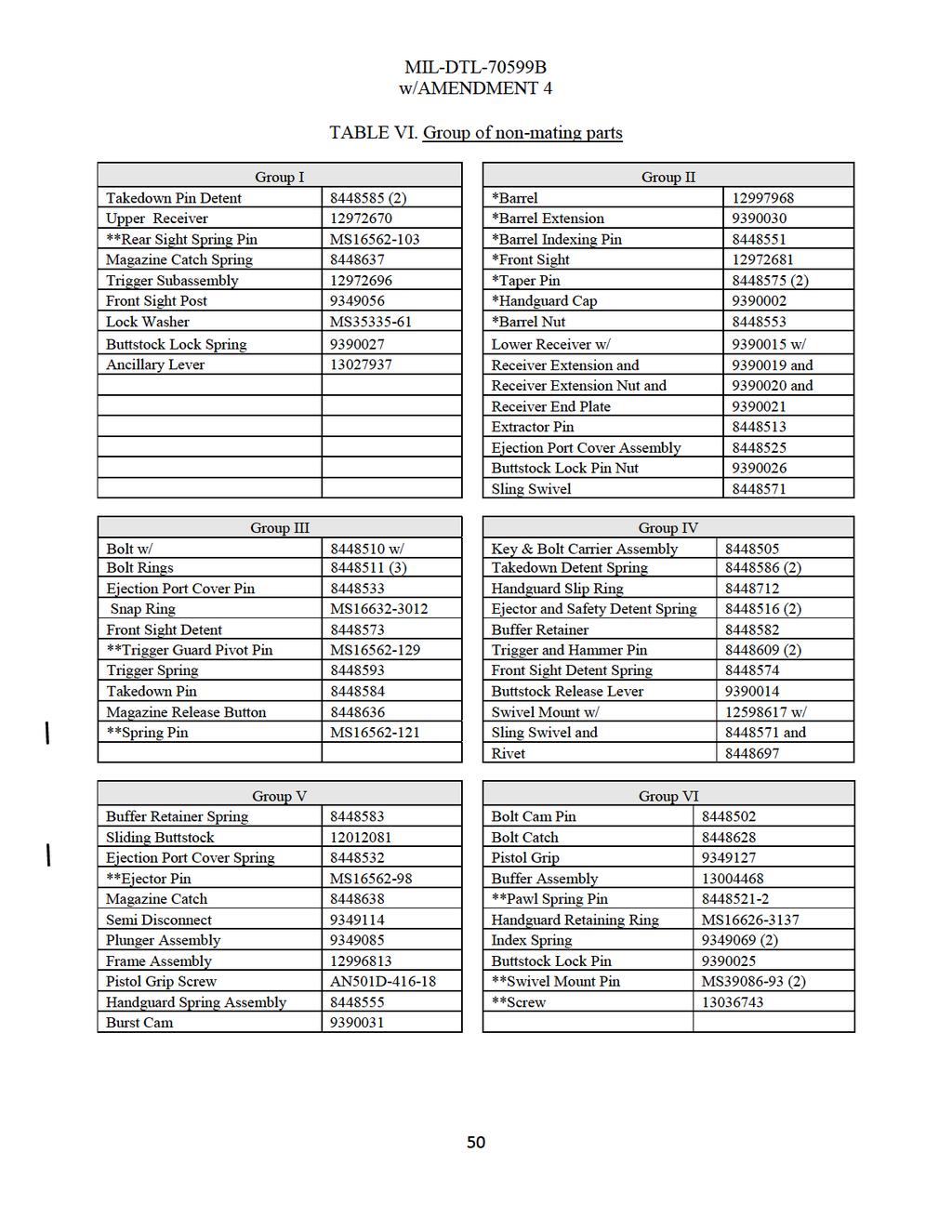
50
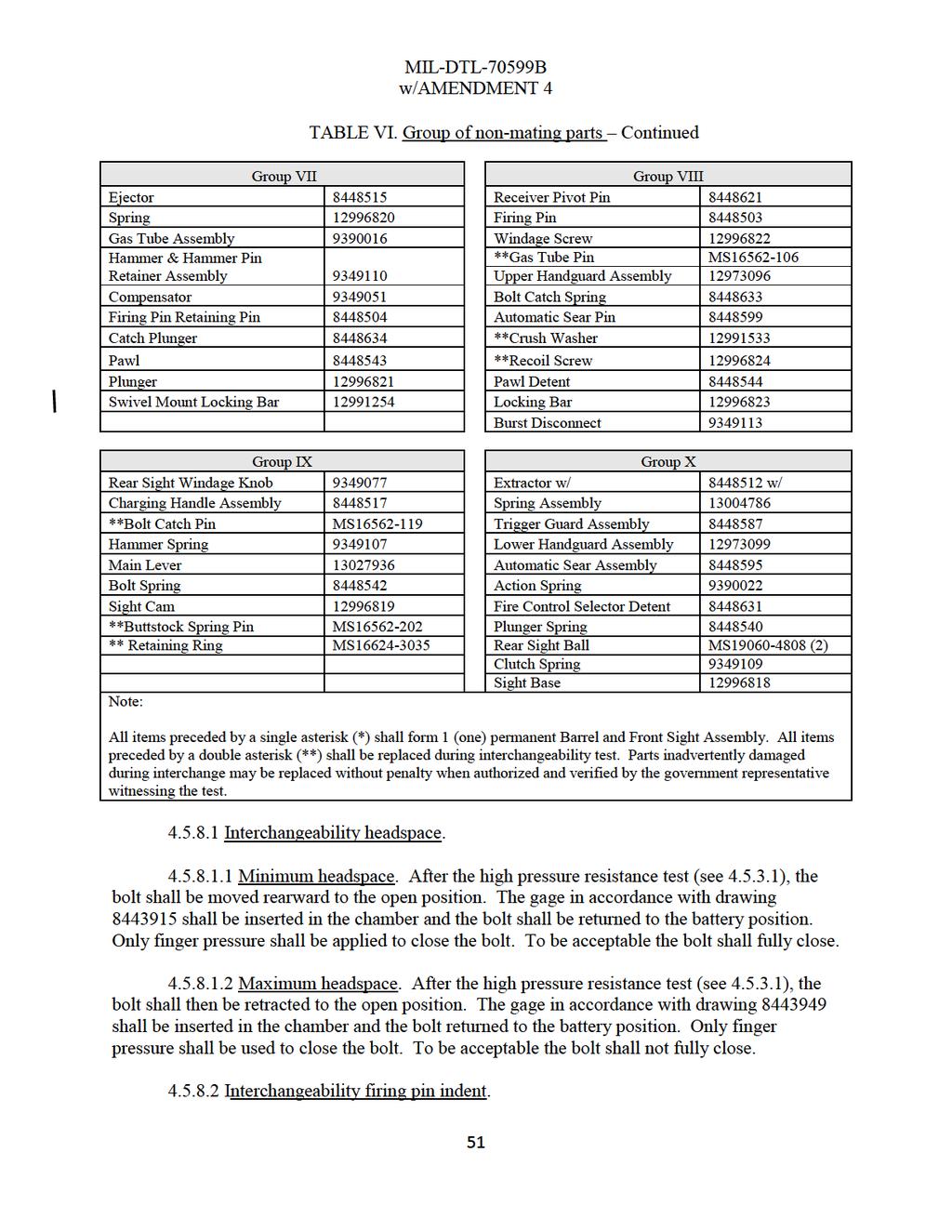
51
OPERATION AND FUNCTION
 CHAPTER 3 OPERATION AND FUNCTION This chapter discusses the operation of the M249 automatic rifle. This includes loading, unloading, cycle of functioning, adjusting the sight, and using the bipod. 3-1.
DETAIL SPECIFICATION GUN, MACHINE; CALIBER.50, BROWNING, M2, HEAVY BARREL
 INCH-POUND MIL-DTL-001298D (AR) w/ AMENDMENT 1 24 March 2008 MIL-DTL-001298D (AR) 25 October 2007 DETAIL SPECIFICATION GUN, MACHINE; CALIBER.50, BROWNING, M2, HEAVY BARREL This specification is approved
REC7 DI OPERATOR S MANUAL
 EC7 D REC7 DI OPERATOR S MANUAL TABLE OF CONTENTS 2 2 4 5 6 6 6 8 8 10 11 12 12 13 13 15 18 20 22 USE OF THIS MANUAL SAFETY GUIDELINES WARRANTY AND SERVICE NOTES FUNCTIONS AND FEATURES BREAK IN PROCEDURE
ARAK-21 OPERATOR SAFETY AND INSTRUCTION MANUAL
 ARAK-21 OPERATOR SAFETY AND INSTRUCTION MANUAL NOTICE: The ARAK-21 Upper Assembly itself is not considered a Firearm under federal law or the National Firearms Act. The ARAK-21 Upper Assembly mounted on
2-1. CLEARING PROCEDURES
 CHAPTER 2 MAINTENANCE Proper maintenance contributes to weapon effectiveness as well as unit readiness. This chapter discusses the maintenance aspects of the M249 AR to include inspection; cleaning and
TM WARNING SUMMARY
 TM 9-005-239-0 WARNING SUMMARY Treat every firearm as if it were loaded. Never accept or take over a firearm from another until you have checked personally to see that it is unloaded or in a completely
M16 R / M1600 R USER S MANUAL WARNING: READ THE INSTRUCTIONS AND SAFETY PRECAUTIONS IN THIS MANUAL CAREFULLY BEFORE USING THIS FIREARM.
 ARMSCOR M16 R / M1600 R USER S MANUAL WARNING: READ THE INSTRUCTIONS AND SAFETY PRECAUTIONS IN THIS MANUAL CAREFULLY BEFORE USING THIS FIREARM. DISCHARGING FIREARMS IN POOLY VENTILATED AREAS, CLEANING
OPERATION AND FUNCTIONING
 C1, FM 23-65 * CHAPTER 3 OPERATION AND FUNCTIONING This chapter explains the operation of the MG. It discusses the loading, unloading, and clearing procedures, and the cycle of functioning of the weapon.
Armed Officer's Training Manual Nomenclature and Inspection
 Armed Officer's Training Manual Section 8: Nomenclature and Inspection Learning Goal: The student will know the components and understand the operation of the service revolver and semi-automatic pistol.
M mm Semiautomatic Rifle
 M4-5.56 mm Semiautomatic Rifle What is the FM concerning the M4 Rifle? FM 3-22.9 What is the first thing you should do when you handle a weapon? Make sure you clear it Name the five phases in Basic Rifle
AR STYLE FIREARMS OWNER'S MANUAL: OPERATION, HANDLING, DISASSEMBLY / REASSEMBLY & SAFETY INSTRUCTIONS
 AR STYLE FIREARMS OWNER'S MANUAL: OPERATION, HANDLING, DISASSEMBLY / REASSEMBLY & SAFETY INSTRUCTIONS - DO NOT DISCARD THIS MANUAL - READ THIS MANUAL CAREFULLY, PAYING CLOSE ATTENTION TO THE INSTRUCTIONS
CHAPTER 1 US ARMY HANDGUNS
 CHAPTER 1 US ARMY HANDGUNS 1-1. PISTOL, SEMIAUTOMATIC, 9-MM, M9 The M9 pistol is a 9-mm semiautomatic, magazinefed, recoil-operated, double-action weapon chambered for the 9-mm cartridge. The magazine
-
 Operator s manual SM-95202 Brügger & Thomet AG P.O. Box 42 3608 Thun Switzerland Fon +41 33 334 67 00 Fax +41 33 334 67 01 info@brugger-thomet.ch www.brugger-thomet.ch TABLE OF CONTENTS SAFETY instructions
FRONT BOLT ACTION ASSAULT SHOTGUN
 SPECIFICATIONS: CATEGORY........... IMPROVISED; NOTE: CAN BE MANUFACTURED COMMERCIALLY CALIBRE............ 410 TO 12 GAUGE; ADAPTABLE CAPACITY............... 8 TO 10 ROUNDS,.410 CAL. OPERATION..........
CHECK OUT OUR WEBSITE SOME TIME FOR PLENTY OF ARTICES ABOUT SELF DEFENSE, SURVIVAL, FIREARMS AND MILITARY MANUALS.
 CHECK OUT OUR WEBSITE SOME TIME FOR PLENTY OF ARTICES ABOUT SELF DEFENSE, SURVIVAL, FIREARMS AND MILITARY MANUALS. http://www.survivalebooks.com/ Thank you for purchasing our ebook package. *TB 9-1000-237-12
Chapter 11 Small Arms Weapons
 Review Questions Chapter 11 Small Arms Weapons 1. On an M16 rifle, where is the magazine release button located? 1. Right side of the weapon, top front of the trigger guard 2. Right side of the weapon,
P9S Automatic Pistol Caliber.45 ACP
 P9S AUTOMATIC PISTOL Caliber.45 ACP P9S Automatic Pistol Caliber.45 ACP Instruction Manual HECKLER & KOCH, INC. 2148 Pacific Boulevard Sterling, Virginia 20166-8903 U.S.A. TEL. (703) 450-1900 TELEFAX (703)
AR /.223, 300 BLK, 22 Nosler,.224 Valkyrie. Covers. and. rifle models INSTRUCTION MANUAL
 AR-15 5.56/.223, 300 BLK, 22 Nosler,.224 Valkyrie Covers TM, TM and, TM rifle models INSTRUCTION MANUAL WARNING: BEFORE USING THIS FIREARM, READ AND FOLLOW THESE INSTRUCTIONS Safety First Thank you for
Be sure the cam pin is installed in the bolt group. If it isn t, your rifle can still fire and will explode causing injury.
 Responsibility This manual provides instructions on the operation and maintenance of the Barrett model M468 rifle. Read and understand it carefully before you try to use your rifle. Your safety, and that
ODEL 95 OPERATOR S MANUAL
 ODEL 95 MODEL 95 OPERATOR S MANUAL TABLE OF CONTENTS 2 2 3 5 6 6 6 7 7 8 8 11 11 12 12 19 20 22 24 26 MANUFACTURER S DISCLAIMER USE OF THE MANUAL SAFETY GUIDELINES WARRANTY AND SERVICE DESCRIPTION OF FIREARM
INNOVATIVE REFINEMENTS TO THE TACTICAL CARBINE
 INNOVATIVE REFINEMENTS TO THE TACTICAL CARBINE www.usamade-ar15parts.com USER MANUAL AR15 STYLE RIFLES Barnes Precision Machine A2-Style muzzle device. Reduces muzzle blast and felt recoil, complete with
AR-15 Rifle Operator Maintenance
 AR-15 Rifle Operator Maintenance These procedures cover how to Clean, Inspect and Lubricate the AR15 Rifle NOTICE: This is not a replacement for the manufacturer s manual. If you do not have the owners
COLT AUTOMATIC PISTOL
 COLT AUTOMATIC PISTOL CALIBER.22 INSTRUCTIONS FOR ASSEMBLY - DISASSEMBLY CLEANING COLT AIUTOMATIC PISTOL IN 6 INCH OR 4}~2 INCH BARREL.22 Long Rifle, rim fire Cartridge Capacity of Magazine, 10 Shots Description
Figure 2-1. SAFE ( S ) position.
 position.") CHAPTER 2 OPERATION AND FUNCTION This chapter includes clearing, disassembly and assembly, loading, operating precautions, and cycle of operation. 2-1. CLEARING Clear the MK 19 differently in a firing
CHAPTER 2 OPERATION AND FUNCTION This chapter includes clearing, disassembly and assembly, loading, operating precautions, and cycle of operation. 2-1. CLEARING Clear the MK 19 differently in a firing
OWNER S MANUAL. Read the instructions and warnings in this manual carefully before using this firearm; do not discard this manual.
 OWNER S MANUAL SDP compact Read the instructions and warnings in this manual carefully before using this firearm; do not discard this manual. This instruction manual should always accompany this firearm
SAR-15 RIFLE OWNERS MANUAL
 SAR-15 RIFLE OWNERS MANUAL SIONICS WEAPON SYSTEMS Our mission is to manufacture quality firearms made with pride in the USA. We are able to do accomplish this by using only the best American made parts.
Model 82A1 OPERATOR S MANUAL
 82A1 Model 82A1 OPERATOR S MANUAL TABLE OF CONTENTS 2 2 3 3 5 6 7 7 7 8 8 10 14 17 18 19 20 21 23 24 28 32 MANUFACTURER S DISCLAIMER WARRANTY AND SERVICE USE OF THIS MANUAL SAFETY GUIDELINES DESCRIPTION
MILITARY SPECIFICATION. CARTRIDGE 5.56mm, BALL, M855. MIL-C-63989C was inactivated after 15 September 1996 For New Design.
 INCH-POUND MIL-C-63989C (AR) 30 January 2001 SUPERSEDING AMENDMENT 3 15 October 1999 MILITARY SPECIFICATION CARTRIDGE 5.56mm, BALL, M855 MIL-C-63989C was inactivated after 15 September 1996 For New Design.
PISTOL CALIBER AR STYLE FIREARMS
 PISTOL CALIBER AR STYLE FIREARMS OWNER'S MANUAL: OPERATION, HANDLING, DISASSEMBLY / REASSEMBLY & SAFETY INSTRUCTIONS - DO NOT DISCARD THIS MANUAL - READ THIS MANUAL CAREFULLY, PAYING CLOSE ATTENTION TO
MECH-TECH SYSTEMS CCU MODEL FOR GLOCK PISTOLS
 MECH-TECH SYSTEMS CCU MODEL FOR GLOCK PISTOLS Operation & Maintenance Manual Read and understand this manual before attempting to use this product. If you have any questions call: 1-866-433-2122 www.mechtechsys.com
Colt Advanced Law Enforcement Carbines
 OPERATOR S MANUAL FOR: Colt Advanced Law Enforcement Carbines LE6940 LE6944 LE6943 LE6945CQB & LE6946CQB COPYRIGHT 2010 COLT DEFENSE LLC ALL RIGHTS RESERVED Information contained in this publication is
 (Mechanical Malfunctions) STOP SHOOTING IMMEDIATELY AND UNLOAD YOUR FIREARM if your firearm develops: a mechanical malfunction; binding or stoppage; spitting powder/gas; a punctured cartridge primer; a
Military Assault Rifle Operator Manual
 Military Assault Rifle Operator Manual 22 WARNINGS - Never Point any weapon, loaded or unloaded, at anything you do not intend to shoot. - Load and Unload with the muzzle pointed in a safe direction. -
INTRODUCTION TO THE SERVICE RIFLE AND MAINTENANCE
 INTRODUCTION TO THE SERVICE RIFLE AND MAINTENANCE 1 OVERVIEW DISASSEMBLY MAINTENANCE ASSEMBLY 2 TERMINAL LEARNING OBJECTIVE Given a service rifle, Common Combat Sling, and cleaning gear maintain a service
CZ52 Detail Strip, Disassembly, and Assembly Instructions Lonestar Fabrication & Design
 CZ52 Detail Strip, Disassembly, and Assembly Instructions 2008 Lonestar Fabrication & Design These instructions may be freely distributed and copied providing this page is included, and providing they
MARINE CORPS INSTITUTE INSPECTION AND REPAIR OF THE M9 PISTOL
 MARINE CORPS INSTITUTE INSPECTION AND REPAIR OF THE M9 PISTOL MARINE BARRACKS WASHINGTON, DC Table of Contents Page Contents... Navigation Instructions... i iii Chapter 1 Disassembly and Assembly of the
OWNER S MANUAL FOR OA SERIES FIREARMS
 OWNER S MANUAL FOR OA SERIES FIREARMS 620-626 Old Pacific Hwy SE Olympia, WA 98513 (360) 459-7940 WARNING To avoid accidental firing, BE SURE WEAPON IS CLEAR. Failure to do so could result in serious injury
WORLD CHAMPION. SMALL BORE RIFLE.22 l.r. MANUAL. Technical Innovations
 SMALL BORE RIFLE.22 l.r. MANUAL Technical Innovations Technical Innovations -General information Page 2 -Bedding Page 3 -Three locking lugs Page 4 -Safety / dry fire switch Page 4 -Firing pin Page 4 -Firing
SPECIFICATION LAUNCHER, GRENADE, 40MM: DETACHABLE, M203
 MILITARY SPECIFICATION LAUNCHER, GRENADE, 40MM: DETACHABLE, M203 5 September 1974 SUPERSEDING MIL-L-45935 24 September 1971 (see Section 6) This specification is approved for use by all Departments and
SAAMI. Semi-Automatic Assault Shotgun Owner s Manual. Tel. : Fax
 Head Quarter Beyşehir Organize Sanayi Bölgesi Bayavşar Mah. 4959 Sk. No.24-42700 Beyşehir - Konya / TURKEY Tel. : +90 332 524 60 32-34 - Fax +90 332 524 62 4 - info@deryaarms.com SAAMI SPORTING ARMS AND
STRIBOG GRAND POWER. The INSTRUCTIONS FOR USE, MAINTENANCE AND SAFETY. 1
 instructions The for use, maintenance STRIBOG and safety hestribog GRAND POWER INSTRUCTIONS FOR USE, MAINTENANCE AND SAFETY www.grandpower.eu 1 The STRIBOG Dear Customer, Thank you for purchasing a semi-automatic
MODEL 1400 E USER S MANUAL WARNING: READ THE INSTRUCTIONS AND SAFETY PRECAUTIONS IN THIS MANUAL CAREFULLY BEFORE USING THIS FIREARM.
 ARMSCOR MODEL 1400 E USER S MANUAL WARNING: READ THE INSTRUCTIONS AND SAFETY PRECAUTIONS IN THIS MANUAL CAREFULLY BEFORE USING THIS FIREARM. DISCHARGING FIREARMS IN POORLY VENTILATED AREAS, CLEANING FIREARMS
UNITED STATES MARINE CORPS WEAPONS TRAINING BATTALION MARINE CORPS COMBAT DEVELOPMENT COMMAND QUANTICO, VIRGINIA INSTRUCTOR GUIDE
 UNITED STATES MARINE CORPS WEAPONS TRAINING BATTALION MARINE CORPS COMBAT DEVELOPMENT COMMAND QUANTICO, VIRGINIA 22134-5040 INSTRUCTOR GUIDE CORRECTIVE ACTION WITH A SERVICE RIFLE 0300-M16-1003 0300-M16-1017
CETME. SPECIAL PURPOSE ASSAULT MACHINEGUN 5.56x45 DESCRIPTIVE HANDBOOK
 , CETME SPECIAL PURPOSE ASSAULT MACHINEGUN 5.56x45 DESCRIPTIVE HANDBOOK , SPECIAL PURPOSE ASSAULT MACHINEGUN 5.56x45 DESCRIPTIVE HANDBOOK Patent Pending ,. SPAM 5.56x45 INDEX I. Technical characteristics................................
CONTENTS INTRODUCTION. WARNING: This manual contains important warnings that must be understood before using this firearm.
 CONTENTS Safety Rules...............................Page 2 Operation................................Page 5 Major Components.........................Page 6 Assembly.................................Page
INSTRUCTION MANUAL FOR. Models featured include: LF556, LF300, LF308, and LF6.5.
 INSTRUCTION MANUAL FOR Models featured include: LF556, LF300, LF308, and LF6.5. READ THIS MANUAL THOROUGHLY, PARTICULARLY THE WARNINGS, BEFORE USING THIS FIREARM Copyright 2016 Live Free Armory. All rights
SHF R50 SHF S50 Safety Harbor Firearms, Inc. PO Box 563 Safety Harbor, FL Ph: Fax:
 SHF R50 SHF S50 Safety Harbor Firearms, Inc. PO Box 563 Safety Harbor, FL 34695-0563 Ph: 727-726-2500 Fax: 727-797-6134 www.safetyharborfirearms.com 1 ^ WARNING Risk of serious injury or death. Failure
SAFETY RULES WARNING: READ THESE SAFETY RULES & OPERATORS MANUAL BEFORE HANDLING YOUR FIREARM
 SAFETY RULES WARNING: READ THESE SAFETY RULES & OPERATORS MANUAL BEFORE HANDLING YOUR FIREARM Never point a firearm at anyone and always keep the muzzle pointed in a safe direction. Always treat all firearms
Owner s Manual Addendum (36310, 36311)
") FN15 DMR Owner s Manual Addendum (36310, 36311) We are pleased that you have chosen an FNH USA FN 15 Designated Marksman Rifle (DMR). The FN 15 DMR shares the same reliability, durability, quality and
FN15 DMR Owner s Manual Addendum (36310, 36311) We are pleased that you have chosen an FNH USA FN 15 Designated Marksman Rifle (DMR). The FN 15 DMR shares the same reliability, durability, quality and
Smallbore rifle CZ99 PRECISION..22 Long Rifle.22 Win. Mag. R.F..17 Hornnady Mag. R.F.
 Smallbore rifle CZ99 PRECISION.22 Long Rifle.22 Win. Mag. R.F..17 Hornnady Mag. R.F. Fig. 1 22. Long Rifle, Model CZ 99 PRECISION 22 Long Rifle 22 Long Rifle for Sound Moderator 22 Win. Mag. R. F. 17
VR1 Owner s Manual. Vigilance Rifles, Inc Plum Lane Redlands, CA P F
 VR1 Owner s Manual Vigilance Rifles, Inc. 1653 Plum Lane Redlands, CA 92374 P 909.307.8877 F 909.307.8866 www.vigilancerifles.com INTRODUCTION: Vigilance Rifles offers a new line of Semi-Automatic Rifles
ZEV// SINGLE STAGE RIFLE TRIGGER (SSR)
") NON FACTORY INSTALLATION INSTRUCTIONS WARNING Zero liability is expressed or implied for damage, injury, or death resulting from the improper installation or use/misuse of this product. It is strongly
NON FACTORY INSTALLATION INSTRUCTIONS WARNING Zero liability is expressed or implied for damage, injury, or death resulting from the improper installation or use/misuse of this product. It is strongly
Kentucky Long Rifle.50 BMG Model: BA M-N-M Tactical. Users Guide
 Kentucky Long Rifle.50 BMG Model: BA M-N-M Tactical Users Guide Metals-N-More Bowling Green, KY 42101 Telephone 270-781-3642 Fax 270-781-3766 Email Info@Kentucky50.Com www.kentucky50.com INTRODUCTION Congratulations
40-MM GRENADE LAUNCHER, M79
 APPENDIX A 40-MM GRENADE LAUNCHER, M79 This appendix provides guidance for US Army units to conduct training with the M79 grenade launcher. The weapon s characteristics, disassembly and assembly procedures,
Introduction 4-5 Ten commandments of safety 6-12 Important Parts & Mechanism Loading and Firing Unloading 24 Cleaning Complete
 www.utasarms.com www.utasarms.com www.utasarms.com Introduction 4-5 Ten commandments of safety 6-12 Important Parts & Mechanism 13-15 Loading and Firing 16-23 Unloading 24 Cleaning 25-28 Complete Disassembly
Before handling the firearm read this manual carefully and observe the following safety instructions. CONTENTS
 Before handling the firearm read this manual carefully and observe the following safety instructions. Improper and careless handling of the firearm could result in accidental discharge and cause injury,
SIG SAUER ENHANCED AUTO MIL SPEC TRIGGER KIT INSTALLATION INSTRUCTIONS
 SIG SAUER ENHANCED AUTO MIL SPEC TRIGGER KIT INSTALLATION INSTRUCTIONS 1.0 Warnings 2 www.sigsauer.com This SIG SAUER Enhanced Mil-Spec Auto Trigger Kit comes complete with all parts and detailed installation
XM8 US M4 System Comparison
 XM8 US M4 System Comparison HECKLER & KOCH DEFENSE Inc. System Weight: Overall Length: XM8 Lightweight Modular Weapon System (includes integrated sight with IR laser & illuminator, red dot reflex sight,
22-17 Partner. Owner s Manual. 624 Old Pacific Hwy SE Olympia, WA Tel (800) Fax (360) Available Rifle Kit
 Fax (360) Available Rifle Kit") Available Rifle Kit Complete Upper Receiver Kit 624 Old Pacific Hwy SE Olympia, WA 98513 Tel (800) 228-3471 Fax (360) 491-3447 Owner s Manual 22-17 Partner Warnings & Operation Do not attempt to fire the
Available Rifle Kit Complete Upper Receiver Kit 624 Old Pacific Hwy SE Olympia, WA 98513 Tel (800) 228-3471 Fax (360) 491-3447 Owner s Manual 22-17 Partner Warnings & Operation Do not attempt to fire the
Barrel Assembly. Field Stripping
 WARNINGS: Carry out safety check before handling the weapon. The weapon is heavily oiled for shipping. Clean and lubricate before firing. These procedures given apply only to the US Ordnance QCB version.
ENR Enterprises, LLC. ENR 15 Manual
 ENR Enterprises, LLC ENR 15 Manual Table of Contents Disclaimer of Liability 2 Warnings: Dangerous Procedures 3 General Safety Warnings 4 Main Features and Overview 6 Rifle Clearing Before Use 7 Safety
SIGM400 OWNERS MANUAL: HANDLING & SAFETY INSTRUCTIONS
 SIGM400 OWNERS MANUAL: HANDLING & SAFETY INSTRUCTIONS READ THE INSTRUCTIONS AND WARNINGS IN THIS MANUAL CAREFULLY BEFORE USING THIS FIREARM; DO NOT DISCARD THIS MANUAL. This instruction manual should always
KEL-TEC PLR-16 Pistol
 KEL-TEC PLR-16 Pistol SAFETY, INSTRUCTION & PARTS MANUAL STATEMENT OF LIABILITY This pistol may be classified as a dangerous weapon and is surrendered by KEL-TEC CNC INDUSTRIES INC. with the understanding
Manual Provided by emilitary Manuals-
 WAR DEPARTMENT TECHNICAL MANUAL TM 9-1276 This manual supersedes TM 9-1276, Ordnance Maintenance, Carbines, Cal..80, Ml and M1A1, 5 June 1943; TB 9-1276-1,15 January 1945; TB ORD 9, 10 January 1944; and
AR15/ BCA 10 RIFLE OWNER S MANUAL
 AR15/ BCA 10 RIFLE OWNER S MANUAL THIS IS NOT A SAFETY MANUAL. IF YOU NEED ASSISTANCE WITH THE SAFE HANDLING OF THIS, OR ANY FIREARM, PLEASE CONTACT A CERTIFIED FIREARMS INSTRUCTOR OR SCHOOL. Fundamental
INSTRUCTION MANUAL CZ 75 TS
 INSTRUCTION MANUAL CZ 75 TS CZ 75 TS - INSTRUCTION MANUAL Before handling the pistol read this manual carefully and observe the following safety instructions. Improper and careless handling of the pistol
MRAD. Operator s Manual. (Multi-Role Adaptive Design) PO Box 1077 Murfreesboro, TN USA / / FAX /
 PO Box 1077 Murfreesboro, TN USA / / FAX /") MRAD (Multi-Role Adaptive Design) Operator s Manual PO Box 1077 Murfreesboro, TN 37133 USA / 615.8962938 / 615.896.7313 FAX / mail@barrett.net 03-23-11 P# 12925 Use of this manual Before you handle the
MRAD (Multi-Role Adaptive Design) Operator s Manual PO Box 1077 Murfreesboro, TN 37133 USA / 615.8962938 / 615.896.7313 FAX / mail@barrett.net 03-23-11 P# 12925 Use of this manual Before you handle the
MR762A1 LRP LONG RIFLE PACKAGE OPERATOR S MANUAL
 MR762A1 LRP LONG RIFLE PACKAGE OPERATOR S MANUAL Covering MR762A1 7.62 x 51 mm and Long Rifle Package variant SAFETY PRECAUTIONS CAUTION: Read these safety rules before handling the firearm! Read this
OPERATOR S MANUAL FOR AR-24 SERIES PISTOLS
 OPERATOR S MANUAL FOR AR-24 SERIES PISTOLS ArmaLite Incorporated Box 299 Geneseo Illinois U.S.A. 61254 309-944-6939 ArmaLite.com 2006 ArmaLite Inc. This book provides instructions on the operation and
OWNER S MANUAL. Read the instructions and warnings in this manual carefully before using this firearm; do not discard this manual.
 OWNER S MANUAL VECTOR GEN II SDP SBR CRB Read the instructions and warnings in this manual carefully before using this firearm; do not discard this manual. This instruction manual should always accompany
USER MANUAL Z-SERIES. RIFLE 7.62x51 mm. Zenith Firearms V.01
 Firearms Z x51 Zenith Firea 41 Rifle 7.6 2 x51 Zenith Fir Rifle MKEK R Zenith Firearms x51 Z-41 Rif Z-SERIES RIFLE 7.62x51 mm USER MANUAL V.01 INDEX Z-41 RIFLE... 2 Z-41 RIFLE TECHNICAL SPECIFICATIONS...
A. Safety Information and Warnings... 2 B. Overview Description... 4 Nomenclature... 4 Specifications... 4 Ammunition... 5 Sling Mounting...
 TABLE OF CONTENTS A. Safety Information and Warnings... 2 B. Overview Description... 4 Nomenclature... 4 Specifications... 4 Ammunition... 5 Sling Mounting... 5 C. Operating Instructions Safety... 6 Loading
YES CORRECT WRONG. KSG-TACTICAL Specifications Operating System Pump Action Capacity (Dual Magazines)
") YES CORRECT NO WRONG KSG-TACTICAL Specifications Operating System Pump Action Capacity (Dual Magazines) 4+4+1, 3 shells 5+5+1, 2.75 shells Chamber 12-gauge 3.00 (76 mm) Barrel Length 13.7 (410 mm) Length
YES CORRECT NO WRONG KSG-TACTICAL Specifications Operating System Pump Action Capacity (Dual Magazines) 4+4+1, 3 shells 5+5+1, 2.75 shells Chamber 12-gauge 3.00 (76 mm) Barrel Length 13.7 (410 mm) Length
M1 Garand Operation and Maintenance Guide for Veteran and Civilian Service Organizations, Law Enforcement, and National Cemeteries
 M1 Garand Operation and Maintenance Guide for Veteran and Civilian Service Organizations, Law Enforcement, and National Cemeteries 12 December 2012 Prepared by Armament Research, Development, and Engineering
Owner s Manual FIREARMS SAFETY IS THE SOLE RESPONSIBILITY OF THE SHOOTER. ALWAYS TREAT ALL FIREARMS AS IF THEY WERE LOADED AT ALL TIMES!
 CENTURION 39 SPORTER RIFLE Owner s Manual Cal. 7.6x39MM 00% American Made! Congratulations on your purchase of the Centurion 39 Sporter Rifle. With proper care and handling, it will give you long, reliable
MR762A1 OPERATOR S MANUAL
 MR762A1 OPERATOR S MANUAL Covering MR762A1 7.62 x 51 mm Rifle (all configurations) SAFETY PRECAUTIONS CAUTION: Read these safety rules before handling the firearm! Read this operators manual before handling
Automatgevär m/ 42 B Manual
 Automatgevär m/ 42 B Manual A translation from the 1969 Swedish Army Manual (SoldI Mtrl) Translated by Anders & Petter. Anders website: http://www.geocities.com/pentagon/quarters/1106 Petter s website:
SASS M110 Repair Parts
 HOURLY REPAIR RATE $ CONTRACTOR REPAIR/REPLACEMENT 25362 2-Stage Match Trigger, 4.5 lbs. N/A 25362 94354 Trigger N/A 25362 94031 Spring, Sear N/A 25362 25361 Match Front Hook, (Sear) (6-40 Threaded) N/A
PERFORMANCE SPECIFICATION
 INCH-POUND 26 September 2007 SUPERSEDING MIL-PRF-83867C (USAF) 10 August 1998 PERFORMANCE SPECIFICATION CONNECTOR, OXYGEN MASK HOSE, NON-EJECTION TYPE This specification is approved for use by the Department
CHAPTER 2 MAINTENANCE
 CHAPTER 2 MAINTENANCE This chapter addresses the proper care of the machine gun to ensure its overall effectiveness and efficient functioning. The information includes the gunner's knowledge in disassembly
FX IMPACT OWNER S MANUAL
 made in sweden FX IMPACT OWNER S MANUAL Warranty Information All FX Airguns carry a One Year Warranty against faulty workmanship and defective materials. If it becomes necessary, first contact the dealer
Before handling the pistol read this manual carefully and observe the following safety instructions. CONTENTS
 Before handling the pistol read this manual carefully and observe the following safety instructions. Improper and careless handling of the pistol could result in unintentional discharge and could cause
INSTRUCTION MANUAL CZ 75 Champion
 INSTRUCTION MANUAL CZ 75 Champion CZ 75 CHAMPION - INSTRUCTION MANUAL Before handling the pistol read this manual carefully and observe the following safety instructions. Improper and careless handling
1911 Pistol. owner s Manual
 1911 Pistol owner s Manual IMPORTANT! This manual contains operating, care, and maintenance instructions. To assure safe operation, any user of this firearm must read and understand this manual before
Division Of ARMALITE, INC OWNER S MANUAL FOR AR-10 RIFLES AND CARBINES
 Division Of ARMALITE, INC OWNER S MANUAL FOR AR-10 RIFLES AND CARBINES READ THIS MANUAL THOROUGHLY, PARTICULARLY THE WARNINGS, BEFORE USING THIS FIREARM! IT S IMPORTANT! Copyright ArmaLite, Inc. ArmaLite
MR556A1 OPERATOR S MANUAL
 MR556A1 OPERATOR S MANUAL Covering MR556A1 5.56 x 45 mm Rifle & MR556A1 Upper Receiver Kit SAFETY PRECAUTIONS CAUTION: Read these safety rules before handling the firearm! Read this operators manual before
TABLE OF CONTENTS READ FIRST
 TABLE OF CONTENTS READ FIRST PAGE INTRODUCTION............................. 1 NOTICES.................................. 1 WARNINGS................................ 2 PRECAUTIONS WHEN USING THIS FIREARM......
KEL-TEC PLR-22 Pistol and SU-22 Rifle
 KEL-TEC PLR-22 Pistol and SU-22 Rifle SAFETY, INSTRUCTION & PARTS MANUAL STATEMENT OF LIABILITY This firearm may be classified as a dangerous weapon and is surrendered by KEL-TEC CNC INDUSTRIES INC. with
USC OPERATOR S MANUAL
 USC OPERATOR S MANUAL Covering all models of the Universal Self-loading Carbine.45 ACP SAFETY PRECAUTIONS CAUTION: Read these safety rules before handling the carbine! Read this operators manual before
OPERATOR S MANUAL. FOR ALL ARMALITE M15 and AR-10 RIFLES. ArmaLite P.O Box 299 Geneseo, Illinois (309) Copyright ArmaLite April, 2004
 Copyright ArmaLite April, 2004") OPERATOR S MANUAL FOR ALL ARMALITE M5 and AR-0 RIFLES READ THIS MANUAL FIRST! Almost all customer problems are caused by failure to read and understand the information in this manual. It s Important! Copyright
OPERATOR S MANUAL FOR ALL ARMALITE M5 and AR-0 RIFLES READ THIS MANUAL FIRST! Almost all customer problems are caused by failure to read and understand the information in this manual. It s Important! Copyright
HATFIELD. Continuing the Tradition SEMI-AUTOMATIC SHOTGUN INSTRUCTION MANUAL
 HATFIELD Continuing the Tradition SEMI-AUTOMATIC SHOTGUN INSTRUCTION MANUAL READ THE INSTRUCTIONS AND WARNINGS IN THIS MANUAL CAREFULLY BEFORE USING THIS FIREARM SAFETY HANDLING RULES 1.Always keep the
Warranty TYPE-A MRD/18 LONG RIFLE OPERATOR S MANUAL TYPE-A RIFLE CO. - MRD/18-300BLK
 TYPE-A MRD/18 LONG RIFLE Warranty TYPE-A Rifle Co. LLC will replace all items that are considered unserviceable under general use. Warranty does not apply to any issues or failures that came about from
WARNING. Paintball Pistol. Paintball Pistol
 This lightweight assault paintball pistol is custom milled from high grade aluminum for superb balance and precision. The compact construction of this competition paintball pistol will give you a mobile
STEYR evo 10 E STEYR evo 10 E Compact
 TM STEYR evo 10 E STEYR evo 10 E Compact MATCH Bedienungsanleitung Operator's manual Mode d'emploi Instrucciones de funcionamiento STEYR evo 10 E STANDARD STEYR evo 10 E COMPACT ATTENTION This operator
Paintball Marker. User s Manual. 530 South Springbrook Road Newberg, OR 97132
 Paintball Marker User s Manual 530 South Springbrook Road Newberg, OR 97132 Component Concepts, Inc., 530 South Springbrook Road, Newberg, OR 97132 Phone: (503) 554-8095 Fax: (503) 554-9370 www.phantomonline.com
Disassembly, Assembly, and Cleaning of M16A4/M4
 Table of Contents iii Disassembly, Assembly, and Cleaning of M16A4/M4 By: George Carter Chris Talbott Jeremy Tinker Table of Contents Introduction... vii Disassembly... 3 Clearing the Magazine... 3 Retaining
Defender Series Owner s Manual
 4904 Hwy 98/PO Box 67 Comer, GA 30629 (866) 803-0000 Fax (706-783-5800) Defender Series Owner s Manual MPA1SST & MPA20SST/DMG Carbines MPA10T & MPA10SST Pistols MPA30T & MPA30SST/DMG Pistols When you purchased
INSTRUCTION MANUAL CZ 92
 INSTRUCTION MANUAL CZ 92 Before handling the pistol read this manual carefully and observe the following safety instructions. Improper and careless handling of the pistol could result in unintentional
OD1503 MAINTENANCE OF THE M2 MACHINEGUN
 SUBCOURSE OD1503 EDITION A MAINTENANCE OF THE M2 MACHINEGUN US ARMY TANK TURRET REPAIRER MOS/SKILL LEVEL: 45K30 MAINTENANCE OF THE M2 MACHINEGUN SUBCOURSE NO. OD1503 US Army Correspondence Course Program
Pistol Marksmanship. U.S. Marine Corps MCRP 3-01B DISTRIBUTION STATEMENT A: Approved for public release; distribution is unlimited.
 MCRP 3-01B Pistol Marksmanship U.S. Marine Corps DISTRIBUTION STATEMENT A: Approved for public release; distribution is unlimited. To Readers Unless otherwise stated, whenever the masculine gender is used,