TM LAUNCHER, ROCKET: 66MM, 4-TUBE, M202A1 (NSN ) TECHNICAL MANUAL
|
|
|
- Eugene Blair
- 5 years ago
- Views:
Transcription
1 TM TECHNICAL MANUAL OPERATOR S AND ORGANIZATIONAL MAINTENANCE MANUAL (INCLUDING REPAIR PARTS AND SPECIAL TOOLS LIST) LAUNCHER, ROCKET: 66MM, 4-TUBE, M202A1 (NSN ) This copy is a reprint which includes current pages from Changes 1 through 4. T H E H E A D Q U A R T E R S, D E P A R T M E N T O F T H E A R M Y MARCH 1975
2
3 TM WARNINGS Do NOT use an M74 Rocket Clip when the barrier bag or molded foam overpack is damp or wet. Use of these clips may cause rocket motor blow-up and serious injury or DEATH. Do NOT use rocket clips that are rusted or corroded. Use of these clips may cause rocket motor blow-up and serious injury or DEATH. Do not use an M74 Rocket Clip if any of the following conditions exist; dispose of in accordance with local SOP s: An M74 Rocket Clip shows any evidence of misuse and mishandling. An M74 Rocket Warhead which has leaked TPA agent fill. This condition can be noted by a built-up mound of greyish white colored residue on the warhead surface. Do not dispose of a LEAKING rocket by submerging in water. Thickened pyrophoric agent (TPA) reacts violently upon contact with water. The M202A1 launcher may be unsafe to load and fire. This unsafe condition can exist if the firing pin mechanism assembly has been fully extended without a clip when the trigger handle assembly is in the stowed and locked position. This condition can cause a round to fire upon release of the trigger handle assembly from its stowed position. This weapon generates a potentially hazardous noise level of 170 decibels. When firing the launcher, the gunner and others in the immediate area will wear earplugs which have been fitted by medical personnel. Any launcher with serial numbers 7800 through 9700 and B through B must have a DA Form 2409 which states that *MWO AMC has been applied to prevent serious injury to personnel. The rocket warhead TPA agent fill ignites spontaneously when exposed to air. If an M74 rocket clip is leaking and burning, immediately evacuate the area and take cover. *Limited distribution, no copies available. Change 4 a (b blank)
4
5 TM T ECHNICAL M ANUAL HEADQUARTERS DEPARTMENT OF THE ARMY No W ASHINGTON, DC, 14 March 1975 OPERATOR'S AND ORGANIZATIONAL MAINTENANCE MANUAL (INCLUDING REPAIR PARTS AND SPECIAL TOOLS LIST) LAUNCHER, ROCKET: 66MM, 4-TUBE, M202A1 (NSN C HAPTER 1. Section I. II. C HAPTER 2. Section I. II. III. C HAPTER 3. Section I. II. III. C HAPTER 4. Section I. II. III. IV. V. C HAPTER 5. Section I. II. III. IV. V. VI. VII. VIII. IX. X. C HAPTER A PPENDIX A. B. INDEX C. Paragraph Page A-1 B-1 C-1 Index 1 LIST OF ILLUSTRATIONS Number Title 1-1 M202A1 rocket launcher - closed position. 1-2 M202A1 rocket launcher - open position. 1-3 M202Al rocket launcher with rocket clip - firing position. 1-4 M202Al rocket launcher. 1-5 Firing-pin-mechanism assembly. 1-6 Reflecting-sight assembly. 1-7 Sight reticle patterns and indications. 1-8 Sling assembly. 1-9 M202Al rocket launcher identification and instruction labels Packing and marking M202A1 rocket launcher. 2-1 Trigger-handle assembly. 2-2 M202Al rocket launcher - carrying position. Page Change 4 i
6 TM Number B-1 B-2 B-3 Title M202A1 rocket launcher loading position. Rear danger-zone-area diagram. Prone position left hand on front cover handle. Prone position left hand on base of trigger handle. Sitting position left hand on front cover handle. Sitting position left hand on base of trigger handle. Sitting position left arm extended. Kneeling position left hand on front cover handle. Kneeling position left hand on base of trigger handle. Standing position left hand on front cover handle. Standing position left hand on base of trigger handle. Position on ground of misfire launcher resting on front and rear covers. Removing misfire clip from launcher tubes. Position of removed misfire clip. Special tools. Installation of reflecting-sight assembly. Boresighting launcher. M74 rocket clip. Typical overpack (M74 rocket clip shown). Carrying amunition. Overpacks installed on backpack. M74 rocket. Packing and marking rocket clips. Reflection-sight assembly. Sling assembly. Special tools. Page B-3 B-4 B-5 ii Change 4
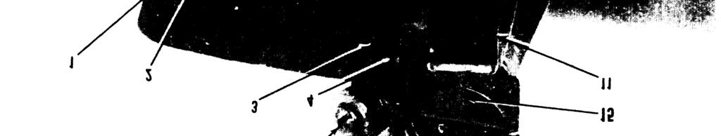
7 TM CHAPTER 1 INTRODUCTION Section I. GENERAL 1-1. Scope These instructions are for use by the operator and organizational maintenance personnel. They apply to the Launcher, Rocket: 66mm, 4-Tube, M202A Record and Report Forms a. Report accidents involving injury to personnel or damage to equipment (other than those involving ammunition) as specified in AR b. Report accidents or malfunctions involving ammunition, which occur in combat or training, as specified in AR c. Complete applicable Department of the Army record and report forms as prescribed in TM d. The reporting of errors, omissions, and recommendations for improving this manual by the individual user is encouraged. Reports should be submitted on DA Form 2028 (Recommended Changes to Publications and Blank Forms) and forwarded directly to Commander, Edgewood Arsenal, Attn: SAREA DE-ET, Aberdeen Proving Ground, Md e. Administrative Storage. Refer to T M for administrative storage instructions Description a. General. The M202A1 rocket launcher (fig. 1-1, 1-2, and 1-3) is a lightweight, shoulder-fired, four-tube launcher equipped with front and rear hinged protective covers. A folding sight and trigger handle assembly provide compact carrying and storage capabilities. An adjustable sling is used to carry the launcher over the shoulder. NOTE All references to right, left, front, rear, top, or bottom indicate the side or end of the launcher as viewed in its firing position. b. Capabilities. The rocket launcher is aim fired from the right shoulder from either the standing, kneeling, sitting, or prone position. Ammunition for the launcher is supplied in rocket clips (fig. 5 1). Each clip is issued preloaded with four rockets that slip-fit into the four launcher tubes, The launcher can fire from one to four rockets semiautomatically at a rate of one per second, and can be reloaded with a new rocket clip. c. Use. The launcher fires the following ammunition: Type Section Il. DESCRIPTION AND DATA Intended use N174 incendiary, thickened An incendiary system pyrophoric agent (TPA) capable of delivering a pyrophoric payload on point or area targets, d. Major Components. (1) Tube assembly. The tube assembly (3, fig. 1 4) consists of four fiberglass launcher tubes. The- tubes are secured to bulkheads and inclosed by closure strips (4). A clip lock button (9) secures the rocket clip in the firing position. (2) Front cover. The front cover (16) protects the muzzle end of the launcher and forms part of the front cover trigger handle interlock (para 2 2e). The cover is hinged to the bottom of the forward bulkhead. The front cover latch (2) secures the cover in the closed position. The handle latch (17) engages with an interlock to secure the cover in the locked (open) position, When the cover is in the down and interlock position, the front cover handle (1) can serve as a forward support to steady the launcher when firing. (3) Rear cover. The rear cover (11) is hinged to the bottom of the rear bulkhead. The rear cover latch (5) secures the rear cover in the closed position. When the cover is in the open (down) position, it becomes a shoulder support to position the launcher. A spare clip latch (10) is stored in the cover. (4) Trigger-handle assembly. The triggerhandle assembly (14) consists of the trigger handle, trigger (15), trigger safety button (13), and linkage drive to the firing mechanism. The handle is extended by opening the front cover to the fully open (down) position, to disengage the 1-1
8 TM Figure 1-1. M202A1 rocket launcher closed position. interlock, and extending the trigger-handle assembly to the locked position. The handle is released by pressing the spring-loaded triggerhandle release button (12). The trigger safety button (13) is moved forward to the safe position or rearward to the fire position to safe or arm the trigger, The linkage drive between the handle assembly and the firing-pin-mechanism assembly (6) is a cable driven ratchet assembly. Each trigger pull rotates the ratchet 90 degrees, which rotates the cam-shaft assembly and releases one firing-pin assembly. (5) Firing-pin-mechanism assembly. (a) Clip attachment slot. A clip attachment slot (3, fig. 1 5) allows the rocket clip (fig. 5-1) to be secured to the firing-pinmechanism assembly by the clip latch (6). (b) Firing-pin housing. The firing-pin housing (4, fig. 1-5) encloses the four firing-pin assemblies each containing a firing pin (2), and a camshaft assembly. Each 90-degree rotation of the camshaft assembly safes the previously fired firing-pin and cocks and releases the next firingpin. (c) Alinement Pin. The align pin (1) alines the four round rocket clips with the firing pin mechanism assembly. (6) Reflecting-sight assembly. The reflecting-sight assembly (fig. 1-6) consists of the reflecting sight (9) and sight lock (11) mounted on an aluminum mounting plate (1). (a) Reflecting sight. The reflecting sight provides the optical line of sight by which the launcher is aimed in azimuth and elevation. The sight has a ladder-type reticle pattern (A, fig. 1-7) with curved stadia lines located on both sides of the vertical centerline. The stadia lines are used to obtain approximate range to targets of predetermined dimensions. The sight reticle has horizontal range lines graduated in 100-meter increments. (b) Sight lock. The sight lock (11, fig. 1-6) is a spring-loaded arm. It positions the reflecting sight in the stored- or firing-position notches of the elevation adjustment plate (2) (c) Mounting plate. The mounting plate (1) contains an elevation adjustment plate (2). The adjustment plate has notches, which are used 1-2
9 TM Figure 1-2. M202A1 rocket launcher open position. Figure 1-3. M202A1 rocket launcher with rocket clip firing position. 1-3

10 TM Figure 1-4. M202A1 rocket launcher. 1-4
11 TM Figure 1-5. Firing-pin-mechanism assembly. to place the reflecting sight in the stored (forward notch) or firing position (rear notch). The adjustment plate allows for elevation adjustments of the sight. At the factory the launcher is boresighted; the mounting plate and adjustment plate are scribed with alinement marks (13) accordingly. (7) Sling assembly. The sling assembly (fig. 1 8) consists of the pad (2) which has two springloaded buckles (1), and two webbed straps (3) which pass through the two pad buckles. Each strap has a snaphook (4) which attaches the sling assembly to the two rings on the right side of the launcher. The web straps are adjustable. e. Rocket Clips. See paragraph 5 2. f. Accessories. Boresight disks, and a wrenchscrewdriver combination tool are packed with the rocket launcher. The boresight disks are used by organizational maintenance personnel during boresighting procedures (para 4-9). The wrenchscrewdriver combination tool is used during maintenance Identification and Instruction Label Figure 1-9 shows the location of launcher identification and instruction labels. 1-5


12 TM Figure 1-6. Reflecting-sight assembly. 1 6
13 TM Figure1-7. Sight reticle patterns and indications Tabulated Data a. M202Al Rocket Launcher. Overall length, closed (approx.) _ 27 in. Overall length, firing position (approx.) _ 35 in. Weight (unloaded) 11.5 lb. Operating temperature limits -27 F. to F. b. Ammunition. See paragraph Packing and Marking a. Packing. One rocket launcher and accessories are packed in a water-vaporproof barrier bag. The bag is packed in a hinged wood box (fig. 1-10) containing cushioning material. The wood box is approximately 33 by 12 by 14 inches and weighs approximately 40 pounds. Cubical displacement is approximately 3.2 cubic feet. b. Marking. The unpainted wood packing box is marked in black with the following information: (1) Lot number. (2) Federal stock number. (3) Gross weight. (4) Cubical displacement. (5) Nomenclature. (6) Quantity and unit of issue. (7) Level of protection and date packed. (8) Contract number or purchase order number. (9) Name and address of contractor. (10) Serial number Expendable Items a. Table 1 1 lists the expendable items required Change 1 1-7
14 TM Figure 1-8. S!ing assembly. to properly maintain and operate the M202A1 rocket launcher. b. The items listed are authorized in accordance with provisions of CTA on expendable items. Item No. Table 1-1. Expedable Items Nomenclature 1 Lusterless OD paint, 2 Antifogging Kit, Ml NSN 1 gal can Change 1

15 TM Figure 1-9. M202A1 rocket launcher identification and instruction labels. 1-9
16 TM Figure Packing and marking M202A1 rocket launcher. 1-10
 Location. The trigger (2, fig. 2-1) is located on the trigger-handle assembly of the launcher. (2) Purpose.")
17 TM CHAPTER 2 OPERATING INSTRUCTIONS Section I. CONTROLS 2-1. General This section describes, locates, and illustrates controls and instruments of the launcher Controls a. Trigger-Handle Assembly. (1) Location. The trigger (2, fig. 2-1) is located on the trigger-handle assembly of the launcher. (2) Purpose. Each complete trigger pull cocks and releases one firing pin which strikes a rocket motor primer. AND INSTRUMENTS b. Trigger Safety Button. (1) Location. The trigger safety button (4) is located on the left side of the trigger-handle assembly. (2) Purpose. The trigger safety button safes or arms the trigger. The button has two positions: (a) Safe (S) position. When the button is pushed forward it is in the safe position and the letter S is visible. (b) Fire (F) position. When the button is Figure 2-1. Trigger-handle assembly. 2-1
18 TM pulled rearward it is in the fire position and the letter F is visible. c. Trigger-Handk Release Button. (1) Location The trigger-handle release button (5) is located at the rear of the trigger-handle assembly base. (2) Purpose. The trigger-handle release button releases the trigger handle assembly from the locked extended position. d. Clip Lock Button. (1) Location. The clip lock button (9, fig. 1-4) is located on the left side of the launcher. (2) Purpose. The clip lock button actuates a detent which holds the rocket clip in the extended firing position. e. Front Cover Trigger Handle Interlock. (1) Location. The trigger handle interlock is located on the bottom of the front cover handle. The interlock retains the front cover in the fully open position when the trigger handle is released from its stowed position. (2) Purpose. This positive safety interlock between the two assemblies assures the cover is fully open before the weapon can be fired. f. Safety Guide. (1) Location. The safety guide is located within the launcher. (2) Purpose. It insures that the firing-pin will retract to a safe position when firing mechanism is fully retracted. Therefore, the firing-pins cannot strike the rocket motor primers when the clip is inserted in the launcher tubes Instrument The reflecting-sight assembly (fig. 1-6) is the only instrument on the M202Al rocket launcher. a. Location. The reflecting sight is located on the left side of the launcher. b. Purpose. The sight is used to aim the launcher. The sight has two positions: (1) Stowed position. The sight lock (11) is positioned in the forward detent and the sight folded against the launcher. (2) Firing position. The sight is folded out from the launcher and the sight lock positioned in the rear detent. The lens cover is opened to view the target. c. Reticle Markings. The sight reticle (a, fig l-7) is graduated in meters. The horizontal range lines of the reticle are graduated in 100-meter increments marked from 0 to 5. The verticle marks on zero azimuth represent 50 meter increments. The length of a horizontal dash and the distance between the dashes each represents 5 mils. Both the dashes and the distances between them are used to obtain estimated lead for targets in motion. The curved stadia lines are used to obtain an approximate range to l0-foot or 20-foot objects. For 20- foot targets, the elevation and azimuth of the launcher are adjusted until the ends of the target image just fit within the bounds of both stadia lines (B). For 10-foot targets, the launcher should be adjusted so that the edges of the target are superimposed between the bounds of the vertical centerline and one of the stadia lines (C) to determine approximate range. After obtaining the range, a stationary target must be centered; a moving target must be placed on the point or sector of the appropriate horizontal range line that will give the required lead. d. Sight adjustment for temperature extremes. Normal sighting of the M202A1 Launcher when firing the M74 rocket will be done as outlined in para 2-3c. However, since the sight on the M202A1 Launcher cannot be adjusted for temperature extremes, the following aiming adjustments should be made for the temperatures and ranges listed below: (1) In a temperature between 0 F and -25 F, with a target range of 250 meters or more, sight 50 meters beyond the estimated target range. (2) In a temperature of 100 F and adove with a target range of 450 meters or more, sight 50 meters less than the estimated target range. Section Il. OPERATION UNDER USUAL CONDITIONS 2-4. General (1) Dented tubes. This section contains instructions for operating the launcher under conditions of moderate temperatures (2) Cracked tubes. and humidity Before-Mission Services a. Remove spent clip or foam pad from launcher. Inspect launcher for damaged, loose/missing parts. Return launcher to organizational maintenance if loose/missing parts or damage is noted. b. Inspect launcher tubes. The launcher will be considered unsafe for firing and returned to organizational maintenance if a visual inspection reveals any of the following conditions. 2-2 Change 3 (3) Unraveled, frayed, or loose fiberglass in any tube. (4) Visible signs of burns on inside of any tube. NOTE The launcher tubes are made of translucent material and are painted. If the paint is chipped off the tubes, light will penetrate them. This is not considered an unsafe condition. c. Perform following procedures for putting launcher in safe mode.
19 TM WARNING The M202A1 launcher may be unsafe to load and fire. This unsafe condition can exist if the firing pin mechanism assembly has been fully extended without a clip when the trigger handle assembly is in the stowed and locked position. This condition can cause a round to fire upon release of the trigger handle assembly from its stowed position. (1) Grasp the front cover handle and rotate it forward until it stops. Be sure the latch is clean. (2) Release latch on top of the launcher to release the front cover. (3) Rotate the cover down below the launcher tubes and lock it in the open position. (4) Trigger handle should rotate freely without force, down to the locked (firing) position. If it does the launcher can be safely operated. If it does not move freely to the locked (firing) position, perform steps 5,6, and 7 below. (5) Open rear cover. Remove empty clip, or foam pad. While applying pressure against the trigger handle in its stowed position, pull out the firing pin mechanism assembly to the fully extended position. This fully extended position must be maintained while performing the next step. (6) While holding the firing pin mechanism in this fully extended position: a. Lock the front door cover in the open position. b. Rotate the trigger handle assembly into the firing position. (7) Retract the firing pin mechanism assembly into the launcher. The launcher can now be safely operated. (8) Make sure trigger safety button is in the forward (safe) position. Press trigger release button and rotate trigger handle assembly to unlock the front cover. Install empty clip or foam pad. Close front and rear covers. d. Check operation of front cover trigger handle interlock. If the front cover interlock does not operate as outlined in (1) through (5) below the launcher is unsafe for use and will be returned to organizational maintenance. (1) Release latch on top of launcher to release front cover. (2) Grasp front cover handle and rotate it forward until it stops. Be sure latch (17, fig. 1-4) is clean. (3) Rotate cover down below launcher tubes and lock it in open position. Use sufficient pressure to release trigger handle from stowed position. (4) Return trigger handle to stowed position to release f rent cover from locked open position. (5) Rotate front cover up and latch it in closed position. e. Check operation of trigger, trigger safety, and firing mechanism. If the trigger, trigger safety and firing pin mechanism do not operate as outlined in (1) through (20) below the launcher is unsafe for use and will be returned to organizational maintenance. (1) Release latch on top of launcher to release front cover. (2) Be sure that latch (17, fig. 1-4) is clean. Grasp front cover handle and rotate it forward until it stops. (3) Rotate cover down below launcher tubes and lock it in open position. Use sufficient pressure to release trigger handle from retracted position. (4) Rotate trigger handle to the locked firing position. (5) Place trigger safety button in forward (safe) position and pull trigger. Trigger should not function. (6) Release latch on top of launcher to release rear cover. (7) Rotate rear cover down and beneath launcher tubes. (8) Grasp firing pin mechanism and fully extend mechanism from launcher keeping it in the same position it was when fully retracted in the launcher. Improper alignment of firing pin mechanism will prevent the trigger from functioning. Hold mechanism firmly while performing operations 9-12 below. (9) Place trigger safety in rear (fire) position. (10) Pull trigger four times to see that each springloaded firing pin releases. If firing pins do not release, slightly rotate firing-pin mechanism to align it (see 8 above) and repeat operation. NOTE The last firing pin released should be in its extended fired position. (11) Place trigger safety in forward (safe) position. (12) Pull trigger. Trigger will operate half of its travel and retract the last fired firing pin from its extended fired position, but should not release (fire) any firing pin. (13) Repeat steps 9 through 11 above. (14) Retract firing pin mechanism into launcher (see fig. 1-2). (15) Check that all firing pins are retracted from their fired position. If any firing pin remains in its extended fired position, the launcher is unsafe for use. Do not load weapon. (16) Place trigger safety in rear (fire) position. Pull trigger. Trigger will operate half of its travel, but should not release (fire) any firing pings. (17) Place trigger safety in forward (safe) position. (18) Install foam pad in launcher; or install spent clip. (19) Close and latch rear cover. (20) Press trigger release button and rotate trigger handle to unlock front cover. Close and latch front cover. f. Perform the following checks. If any defect is Change
20 TM noted return launcher to organizational maintenance. (2) Check that sight alinement marks (13, fig. 1-6) (1) Check reflecting sight for correct operation and are lined up. defects such as bent, loose, or missing parts. Inspect (3) Check sling for damage and adjust for operator. condition of optics to insure clear target definition Change 3
21 TM Loading Weapon a. Procedures for Putting Launcher in Safe Mode Before Loading. WARNING The M202A1 launcher may be unsafe to load and fire. This unsafe condition can exist if the firing pin mechanism assembly has been fully extended without a clip when the trigger handle assembly is in the stowed and locked position. This condition can cause a round to fire upon release of the trigger handle assembly from its stowed position. The following procedures will correct the unsafe conditions described in the above Warning. Additional clips may be loaded and fired without performing the following procedures as long as the operator is positive that the firing pin mechanism assembly has not been extended with the clip removed and the trigger handle assembly in the stowed and locked position. (1) Grasp the front cover handle and rotate it forward until it stops. Be sure the latch is clean. (2) Release latch on top of the launcher to release the front cover. (3) Rotate the cover down below the launcher tubes and lock it in the open position. (4) Trigger handle should rotate freely without force, down to the locked (firing) position. If it does the launcher can be safely operated. If it does not move freely to the locked (firing) position, perform steps 5, 6, and 7 below. (5) Open rear cover. Remove empty clip or foam pad. While applying pressure against the trigger handle in its stowed position, pull out the firing pin mechanism assembly to the fully extended position. This fully extended position must be maintained while performing the next step. (6) While holding the firing pin mechanism in this fully extended position: (a) Lock the front door cover in the open position. (b) Rotate the trigger handle assembly into the firing position. (7) Retract the firing pin mechanism assembly into the launcher. The launcher can now be safely operated. (8) Make sure trigger safety button is in the forward (safe) position. Press trigger release button and rotate trigger handle assembly to unlock the front cover. Install empty clip or foam pad. Close front and rear covers. b. Preparing Rocket Clip for Loading. WARNING Do not use an M74 rocket clip that is damaged, it may cause harm to personnel or launcher damage or rocket malfunction. Damaged rocket clips will be disposed of in accordance with local SOP s. Rocket clips with leaking warheads will be immediately disposed of in accordance with local procedures. (1) Remove rocket clip from packing. (2) Inspect rocket clip to ensure clip latch is installed on rear manifold. NOTE If clip latch is missing, a spare latch is stored in the rear cover of the launcher. (3) Examine rocket clip for any defects. c. Inserting Rocket Clip in Launcher. WARNING Before loading the launcher, make sure the trigger safety is in the forward (safe) position, the firing-pin mechanism assembly is retracted and no firing pin is in the extended fire position. WARNING Do NOT use an M74 Rocket Clip when the barrier bag or molded foam overpack is damp or wet. Use of these clips may cause rocket motor blow-up and serious injury or DEATH. WARNING Do NOT use rocket clips that are rusted or corroded. Use of these clips may cause rocket motor blow-up and serious injury or DEATH. Change 4 2-3


22 TM Figure 2-2. M202A1 rocket launcher - carrying position. 2-4 Change 4
23 TM Figure 2-3. M202A1 rocket launcher loading position. 2-5
24 TM (1) Place launcher on ground resting on closed front cover (fig. 2-3). (2) Open rear cover by releasing rear cover latch on top of launcher. Rotate cover down and beneath launcher tubes. (3) Remove spent rocket clip or foam shipping pad if it is in cover (para 2-11). (4) Check that trigger safety is in the forward (safe) position, the firing pin mechanism assembly is retracted and no firing pin is in the extended fired position. (5) Steady the launcher by holding the sight with left hand. Grasp bail handle and partially insert the rocket clip in the launcher tubes so the bail handle springs down toward the open rear door. Make sure bail handle is clear of the rocket clip tubes. (6) Unsnap clip support strap assembly and discard. (7) Slant rocket clip away from body, depress launcher clip lock button with left thumb and fully insert clip into launcher tubes. Make sure clip retainer is engaged properly to firing mechanism. (8) Close and latch rear cover Carrying Launcher The gunner should carry the closed loaded launcher with its muzzle end down. Position launcher over shoulder as shown in figure 2-2. Adjust sling on the shoulder for individual comfort Preparation for Firing WARNING This weapon generates a potentially hazardous noise level of 170 decibels. When firing the launcher, the gunner and others in the immediate area will wear earplugs which have been fitted by medical personnel. a. Insert earplugs. b. Opening Rear Cover. Rest front cover on ground. Open rear cover. c. Extending Rocket Clip. (1) Hold sight with left hand, grasp bail handle and pull clip until it is locked in the extended position. Listen and feel for the clip s locking detent to fall in place. (2) Release bail handle and allow it to retract against clip s outer tubes. If bail handle will not retract, discard clip. d. Positioning Weapon on Shoulder. (1) Grasp clip tube with right hand and place left hand under launcher. (2) Place weapon on right shoulder so that opened rear cover acts as shoulder support. WARNING During operation procedures in e through i below, keep the launcher pointed toward the target. Insure that all friendly personnel are clear of the rear danger zone area (fig. 2-4). e. Opening Front Cover. (1) Open front cover with left hand. (2) Engage cover handle latch with interlock so the trigger handle releases. f. Extending Trigger Handle. WARNING Position the trigger safety button in the forward (safe) position until ready to fire. Extend trigger handle to the locked firing position. Be sure the trigger safety button is in the forward (safe) position. g. Positioning Sight. (1) Place sight assembly in firing position. (2) Open sight lens cover. h. Checking Rear Danger Zone. Check area to the rear of launcher to assure that all personnel, materiel, and obstructions are clear of the rear danger zone (fig. 2-4). i. Aiming Weapon. Aim weapon by placing eye against sight. Paragraph 2 3 c Firing Weapon WARNING Do not place any portion of the body in front of or behind the launcher while it is in the firing mode. WARNING Do not fire the launcher if a rear vertical obstruction is within 5 meters. The rocket s exhaust gases and materials could be deflected toward the gunner or friendly personnel. WARNING Do not fire rockets at targets less than 20 meters forward of the launcher. The exploding warhead may injure the gunner. WARNING When firing from the prone position, insure that the body is at least 45 degrees to the line of fire in order to keep clear of the rear danger-zone area. a. Launcher may be fired from four positions: prone (fig. 2-5 and 2-6), sitting (fig. 2-7, 2-8, and 2-9), kneeling (fig and 2 11), and standing (fig and 2-13). 2-6
25 TM Figure 2-4. Rear danger-zone-area diagram. 2-7
 position. a. General. The following procedures apply to WARNING clips either empty or containing rockets.")
26 TM Figure 2-5. Prone position left hand on front cover handle. Figure 2-6. Prone position - left hand on base of trigger handle. b. Release the trigger safety by moving safety Post Firing button to the rear (fire) position. a. General. The following procedures apply to WARNING clips either empty or containing rockets. Keep second and third fingers on the right hand spread apart to avoid WARNING pinching the third finger when trigger is During the procedures in b through e fully pulled. below, keep the launcher pointed down range. Insure that all friendly personnel c. Squeeze trigger. Use two fingers with a are clear of the rear danger zone area. smooth steady pressure. Each full squeeze of the trigger will fire one rocket. b. Position trigger safety button to forward NOTE (safe) position. To insure rocket accuracy, sight picture c. Return sight to stowed position. should be maintained until rocket has d. Stow trigger assembly. impacted on target. e. Close and latch front cover. 2 8
27 TM Figure 2-7. Sitting position left hand on front cover handle. 2-9
28 TM Figure 2-8. Sitting position left hand on base of trigger handle. f. Position launcher on ground so it is resting cannot be easily retracted into the on - its closed front cover (fig. 2-3). launcher, DO NOT ATTEMPT TO WARNING FORCE IT. Treat the condition as a If a rocket clip with unfired rockets misfire (para 2-12d (3) through (5)). 2 10


29 TM Figure 2-9. Sitting position left arm extended. 2-11
30 TM Figure Kneeling position left hand on front cover handle. 2 12
31 TM Figure Kneeling position left hand on base of trigger handle. 2 13


32 TM Figure Standing position left hand on front cover bundle. g. Depress launcher clip lock button and fully either rocket or launcher, handle in insert clip into launcher tubes. accordance with procedures in h. Close and latch rear cover. paragraph 2-12d. i. To fire remaining rockets follow para 2-8 and a. Position launcher on ground so it is resting 2-9. on its closed front cover Unloading Weapon b. Open rear cover. c. Remove clip latch. WARNING d. Depress clip lock button and remove clip by When handling a launcher with an using bail handle. extended clip and unknown condition of e. Reinsert clip latch on clip manifold. 2 14


33 TM Figure Standing position left hand on base of trigger handle. 2-15
34 TM f. Close and latch rear cover. g. Return partially loaded clips to proper storage. NOTE If the weapon is being stored install foam or spent clip in launcher (para 2-6c) Misfire, Hangfire, and Mechanical Delay a. Misfire. A misfire is a complete failure of the rocket motor to fire. Although a misfire is not dangerous, it cannot be immediately distinguished from a delay in the functioning of the firing mechanism or from a hangfire. Therefore, it should be considered a delay in firing until such a possibility has been eliminated. b. Hangfire. WARNING Do not assume that an initial failure of a round to fire is a misfire. It may be a hangfire or a mechanical delay. A hangfire is a delay in the functioning of the rocket motor. The amount of delay, although unpredictable, in most cases will range between a split second and several minutes. Therefore, a hangfire cannot be immediately distinguished from a misfire. c. Mechanical Delay. WARNING Do not assume that an initial failure of a round to fire is a misfire. It may be a hangfire or a mechanical delay. A mechanical delay is a delay in functioning of the launcher firing mechanism. d. Procedure. If you pull the trigger of a loaded launcher and the rocket does not fire perform the following WARNING Do not place any portion of the body in front of the launcher or in the rear danger-zone area. WARNING Do not attempt to retract the clip into launcher. Do not use bail handle while removing clip assembly. (1) Keep launcher pointed at target. Pull the trigger four times, after the last dud, to clear the weapon. NOTE If this clears the weapon, remove spent clip and inspect (para 2-5). NOTE If this does not clear the weapon, perform the following (2) Wait 1 minute, keeping the launcher pointed downrange. Place trigger safety in forward (safe) position. (3) Keeping launcher pointed downrange, lower it from the shoulder and place it on a firm surface. Position the launcher so that there is no obstruction in front of or behind the launcher. Figure 2-14 shows recommended position. (4) Then remove the rocket clip from the launcher as follows: (a) Grasp the side of one of the clip tubes (fig. 2-15). (b) Remove clip latch from the clip manifold to separate the launcher firing pin mechanism from the clip. NOTE If the firing-pin mechanism assembly does not automatically retract, carefully insert a blade between the firing-pin mechanism assembly and the clip manifold. Apply enough pressure to separate the firing-pin mechanism assembly from the clip manifold at least one inch. (c) Depress the clip lock button (fig. 2-15) and slide clip out of launcher. (d) Keeping the clip pointed downrange, place it on the ground away from the launcher (fig. 2-16). (e) Dispose of the clip in accordance with local safety procedures. (f) Inspect launcher in accordance with paragraph Emergency Procedures Should An M74 Rocket Leak at launch If an M74 rocket leaks on launch, a small amount of burning TPA may remain in the launcher tube. The following procedures apply: a. Keeping launcher pointed downrange, move trigger safety to forward (safe) position. b. Lower launcher from shoulder and place on the ground. Position launcher so there is no obstruction in front or behind of launcher. c. Remove rocket clip from launcher as follows: (1) Grasp one of the clip tubes (fig. 2-15). (2) Remove clip latch from clip manifold. (3) Depress clip lock button (fig. 2-15) and slide clip out of launcher. (4) Keeping the clip pointed downrange, place it on the ground away from the launcher. (5) Use sand or dirt to extinguish fire burning in launcher. If not possible, allow fire to burn out Change 1
35 TM Figure Position on ground of misfire launcher resting on front and rear covers. Change
36 TM Figure Removing misfire clip from launcher tubes. (6) Handle the clip in accordance with local (2) Evacuate the area at least 60 meters and safety procedures. take cover. Do not move in front of launcher or (7) Inspect launcher in accordance with para- into the rear danger-zone area. graph 2-5. e. Notify authorized personnel. d. If the weapon cannot be cleared of all rockf. Report incident in accordance with AR ets: After Mission Services (1) Place the launcher on the ground keeping Report any launcher defects to organizational the launcher pointed toward the target area (para maintenance. 2-12d(3)). Section Ill. OPERATION UNDER UNUSUAL CONDITIONS General is salty or where extremes in temperature and humidity prevail. Operation under unusual conditions is similar to that for usual conditions (para 2-4 through 2-13) Care and Handling The only differences are in the care and handling of the launcher. Follow instructions in paragraphs a. Keep launcher free of sand, mud, moisture, 2 15 and 2 16 to insure that the launcher func- or any other foreign matter. tions properly in locations where the atmosphere b. If launcher becomes dirty or wet, wipe off at 2-18 Change 1
37 TM Figure Position of removed misfire clip. once with a clean, dry cloth (particularly inside of and ice; inspect, clean, and dry it thoroughly launcher tubes). Observe launcher s operating temperature limits c. Cover launcher to protect it from snow and (para 1-5). ice. d. At low temperatures the lens of sight b. Tropical Conditions. Where temperature assembly tends to fog from gunner s breath. and humidity are excessive or where salt air is Avoid breathing on lens. Keep sight closed when present, inspect and clean launcher daily if not firing. Use M1 antifogging kit (item 2, table required. 1-1). c. Sandy or Dusty Conditions. During sand or Preparing for Operation dust storms, keep launcher covered when operating conditions permit. Wipe it clean as a. Cold Climate. Protect launcher from snow often as necessary. 2 19
38
39 TM CHAPTER 3 OPERATOR S MAINTENANCE INSTRUCTIONS Section I. GENERAL 3 1. Maintenance While the operator has no responsibility of replacing parts he is responsible for preventive maintenance checks and services and troubleshooting the launcher. OPERATOR PREVENTIVE MAINTENANCE CHECKS AND SERVICES Table 3 1 lists the operator preventive maintenance checks and services: Table 3-1. Preventive Maintenance Checks and Services B Before Operation D During Operation A After Operation Time required: Time required: Time required. Interval and Item to be inspected Work Time sequence No. Procedure (H/M) B D A LAUNCHER 1 Perform before mission services (para 2-5) Perform care and handling procedures (para 2-15) and preparing for operation (para 2-16). Section Ill. TROUBLESHOOTING TABLE Possible malfunctions are listed in table 3 2, along with probable causes and corrective actions that can be taken. Symptoms of trouble or malfunctions not listed should be reported to organizational maintenance. Table 3-2. Operator Troubleshooting Item No. Malfunction Probable cause Corrective action 1 Trigger does not release firing pins 1. Trigger safety on. Release safety. during operational check. 2. Defective mechanism. Unsafe. Return launcher to organizational maintenance. 2 Trigger handle does not stay in Worn toggle. Unsafe. Return launcher to retracted position. organizational maintenance. 3 Trigger safety does not safe trigger. Defective mechanism. Unsafe. Return launcher to organizational maintenance. 4 Inaccurate launch firing. Sight not boresighted properly. Return launcher to organizational maintenance for boresighting, 5 Firing pin extended when firing Defective firing pin mechanism and Unsafe. Return launcher to mechanism is fully retracted into or safety guide. organizational maintenance. launcher. 3-1
40
41 CHAPTER 4 ORGANIZATIONAL MAINTENANCE INSTRUCTIONS TM Section I. SERVICE UPON RECEIPT OF MATERIEL I 4.1. Unpacking M202A1 Rocket Launcher CAUTION Do not discard foam pad from inside rear cover until launcher is first used. Subsequent storage should be with an expended clip installed. This will prevent foreign matter from entering launcher s firing mechanism. a. Open wood box cover. b. Tear open barrier bag and remove launcher. 4-2 Inspection All M202A1 Launchers having serial numbers 7800 through 9700; and B through B have been modified in accordance with MWO AMC. An MWO label was attached to each of these launchers after modification. NOTE All launchers with serial numbers B and above have been modified during manufacturer and do not contain a MWO label. WARNING Any launcher with serial numbers 7800 through 9700 and B through B must have a DA Form 2409 which states that MWO AMC has been applied to prevent serious injury to personnel. a. Check DA Form 2409 of launchers with above serial numbers to verify application of MWO. b. If the DA Form 2409 does not state the MWO has been applied or the DA Form 2409 is missing, the launcher will not be issued, and must be returned, through normal supply channels, to depot for modification. c. Inspect launcher para 2-5a through f(1). d. Check to see that sight alinement marks (13, fig. 1-6) are alined (para 4-6e). Boresight if necessary (para 4-9). e. Check to see that the following items are packed with the launcher. (1) (2) (3) (4) (5) (6) (7) (8) Wrench-screwdriver combination tool. Peephole boresight disk, Crosshair boresight disk. Spare clip latch in rear cover. Sling assembly. DA Form (Equipment Control Record), Copy of this manual. DA Form 2409 (Equipment Maintenance Log) Services a. Install sling assembly on launcher attachment rings. b. Touch-up chipped paint. Table 4-1 lists the special packed with the launcher. Section II. TOOLS AND EQUIPMENT tools (fig. 4-1) required for organizational maintenance of the launcher. These tools are Table 4-1. Special Tools Unit of Paragraph Item Issue Reference Use Wrench-screwdriver 1 2-5f,4-5, To loosen, tighten, or remove mounting screws and nuts on combination 4-6, 4-9 the reflecting-sight assembly. Crosshair boresight disk To boresight M202A1 rocket launcher. Peephole boresight disk To boresight M202A1 rocket launcher. Section III. ORGANIZATIONAL PREVENTIVE MAINTENANCE CHECKS AND SERVICES Table 4-2 lists preventive maintenance for the systematic care, inspection, and servicing of the launcher to prvent breakdown and assure maximum operational readiness. Change 2 4-1
 1 2 3 4 5 6 7 8 LAUNCHER Perform operations in paragraph 2-5. Check ding for damage; replace (para 4-7 and 4-8). Check sight for damage.")
42 TM Table 4-2. Organizational Preventive Maintenance Checks and Services A After Operation Time required: 1.6 Inteval and sequence No. Item to be inspected Work times A Procedures (M/H) LAUNCHER Perform operations in paragraph 2-5. Check ding for damage; replace (para 4-7 and 4-8). Check sight for damage. Replace sight and boresight launcher. (para 4-5 and 4-6). Check optical eye shield for damage. Replace eye shield. Check sight alinement marks. (para 4-6e). Touch-up painted surfaces (para 4-10). Tighten any loose screws. Clean launcher A. WRENCH, SCREWDRIVER COMBINATION C. PEEPHOLE BORESIGHT DISK B. CROSSHAIR BORESIGHT DISK AR Figure 4-1. Special tools. 4-2 Change 2
43 TM Section IV. ORGANIZATIONAL TROUBLESHOOTING Table 4 3 lists the most frequently occurring malfunction, its probable causes. and corrective actions. Table 4-3. Troubleshooting Malfunction Probable cause Corrective action 1. Inaccurate launcher firing. a. Sight marks not alined. Realine marks (para 4-6e). b. Damaged sight. Replace sight and boresight launcher (para 4-5, 4-6 and 4-9). 2. Inability to sight launcher. Damaged or missing optical eye shield. Replace optical eye shield. Damaged strap, 3. Nonadjustable sling assembly. buckles or snap Replace (para 4-7 and 4-6). hooks General Organizational maintenance personnel are authorized to repair or replace the reflecting-sight assembly and the sling assembly and to touch up all painted surfaces and maintain DA Form (Equipment Control Record) Removal of Reflecting-Sight Assembly a. Remove and retain the elevation plate screws (12, fig. 1 6), lockwashers, and elevation adjustment plate (2). (Wrench-screwdriver combination tool (A, fig. 3 1) can be used.) CAUTION Press down on the spring loaded sight lock while loosening sight assembly from mounting bushing to eliminate gouging the launcher. Remove sight assembly and curved washer b. (4, fig. 1-6) from sight mounting bushing (3) by turning sight assembly counterclockwise. Retain curved washer Installation of Reflecting-Sight Assembly NOTE The sight assembly must be installed correctly in order to provide the proper degree of snugness to assure accuracy of launcher. a. Position curved washer (4, fig. 4-2) so that concave side is down on mounting bushing (1). CAUTION Press down on the spring loaded sight lock while hand tightening sight assembly in mounting bushing to eliminate gouging the launcher. b. Screw sight assembly (5) clockwise and handtighten sight assembly into mounting bushing until it bottoms. Section V. MAINTENANCE c. Check for proper location of sight lock (7). If sight lock (7) is located between (A) and (B) after completing operation a above, sight is properly installed. If sight lock (7) is not located between (A) and (B), remove sight assembly. Install one or more of the.002 and.010 shims (2 and 3) between curved washer (4) and mounting bushing (1). Repeat a and b until sight lock (7) is correctly located. c. Position sight assembly by turning it counterclockwise until sight lock (7) is between mounting screw holes (11). d. Install elevation adjustment plate (10) with elevation plate screws (8) and lockwashers (9); aline sight marks; and tighten screws. e. Recheck that sight alinement marks (13, fig. 1-6) are alined. If they aren t use the wrenchscrewdriver combination tool (A, fig. 4 1) and perform the following: (1) Loosen the two elevation plate screws (12, fig. 1-6). (2) Position elevation adjustment plate (2) so the mark on the adjustment plate alines with the mark on the mounting plate (1). (3) Tighten the two elevation plate screws. f. Boresight launcher (para 4-9) Removal of Sling Assembly Remove sling assembly from launcher by unsnapping the two snaphooks from the launcher ring assemblies Installation of Sling Assembly Install sling assembly by snapping the snaphooks to the launcher ring assemblies Boresighting M202A1 Rocket Launcher The purpose of boresighting (fig. 4-3) is to check the alinement of the reflecting sight with respect to the bore of the launcher. 4-3
44 TM Figure 4-2. Installation of reflecting-sight assembly. NOTE The reticle is graduated from 0-5 in. hundreds of meters. a. Setting Up. (1) Select a target with a range of at least 150 meters, preferably farther. (2) Place launcher on a secure base. (3) Open front and rear launcher covers. (4) Place reflecting sight in firing position. Open lens cover. (5) Install crosshair boresight disk (B, fig. 4 1) in the muzzle end of the upper left launcher tube. Aline the disk so that TOP is positioned on top. (6) Install peephole boresight disk (C) in the rear of the same launcher tube. b. Checking. (1) Sight through the boresight disks at the target. NOTE If boresight has yards and meters lines, disregard yard line. Position the launcher so that the crosshair boresight disk s proper horizontal line (meters) and vertical line superimpose on the target. Do not move the launcher after this sighting. (2) View through the reflecting sight. (3) If the sight s 0 horizontal line and vertical line are superimposed on the target, boresight is correct. No further adjustment is required. Remove boresight disks. (4) If the sight s lines do not superimpose on the target, adjust for elevation ( c below) or adjust for azimuth (d below), or adjust for both. c. Adjusting for Elevation. (1) Loosen the elevation plate screws (12, fig. 1-6). (2) Sight through the boresight disks at the 4-4
45 TM Figure
46 TM target. Position launcher so that the crosshair boresight disk s proper horizontal line (meters) and the vertical line superimpose on the target. The launcher must not move after this sighting. (3) View through the reflecting sight and move the elevation adjustment plate (2) until the sight s 0 horizontal line superimposes on the target. (4) Tighten the two elevation plate screws. (5) View through the reflecting sight again to see if correct adjustment was made. (6) Recheck launcher-tube alinement by sighting through boresight disks to see if upper horizontal line of the crosshair boresight disk superimposes on the target. If the line does not match the target, repeat (1) through (5) above. (7) When all adjustments have been completed and the original alinement marks (13) are now misalined, obliterate the old mark on the elevation adjustment plate (2). Scribe new mark to lineup with mark on mounting plate. Fill mark with white paint. d. Adjusting for Azimuth. (1) Loosen the stop screw nut (6) and back off stop screw (5) into housing. (2) Loosen hinge stud nut (7). (3) Position the reflecting sight in the firing position. Turn hinge stud (10) right or left until the spring-loaded ball snaps in place in the sight frame detent and the indicator mark (15) on the hinge stud is approximately lined up with the center mark on the sight frame and screwdriver slot (14) is parallel to the mounting plate. (4) Rotate sight to assure detent is engaged. If not, repeat steps (1) through (3) above: NOTE When the spring-loaded ball is properly engaged in the detent, the hinge stud will rotate with the sight only when the hinge nut is loose. (5) Sight through the boresight disks at the target. Position the launcher so that the crosshair boresight horizontal line (meters) and vertical line are superimposed on the target. The launcher must not move after this sighting. (6) View through the sight. Move the sight so the sight s vertical line is either superimposed on target or is slightly to the right of the target. If the sight s vertical line cannot be placed in this position; and if stop screw is completely backedoff (step 1, above), replace sight. (7) Tighten hinge stud nut (7). (8) Turn stop screw (5) until sight s vertical line superimposes on target. (9) Tighten stop screw nut (6). (10) View through reflecting sight and boresight disks to assure correct adjustment was maintained. (11) If adjustment is not correct, repeat (1), (2), and (6) through (10) above. (12) Move sight to closed and open positions to check that the spring-loaded ball in the hinge stud snaps into place at both positions. If not, repeat (1) through (11) above Painting a. Touch up surfaces on launcher where paint is worn or chipped. Do not paint inside of launcher tubes or any part of the firing pin mechanism assembly. b. Mask or cover launcher tubes, firing pin mechanism assembly, identification plates, instruction labels and rubber parts. c. Clean and prime only metal surfaces with zinc chromate primer MIL-P d. Clean and paint surfaces with Finish 20.8 of MIL-STD-171. Use lusterless olive-drab enamel No (item No. 1, table l l) on launcher Disposition of Unserviceable M202A1 Rocket Launcher Rocket launchers found defective during inspection or use will be turned in for proper disposition. 4-6
47 TM CHAPTER 5 AMMUNITION Section I. DESCRIPTION 5-1. General 5-2. Rocket clip Ammunition for the M202A1 rocket launcher is The rocket clip (fig. 5 1) has four aluminum tubes issued in rocket clips of fixed ammunition (the (4), each preloaded with a 66mm rocket (1). The rocket motor propelling charge is not adjustable). tubes are grouped in the same two-by-two pattern The rocket clip consists of four 66mm rockets. as the M202A1 rocket launcher, and they slip-fit Each rocket consists of a warhead, fuze and into the launcher tubes. The clip tubes are rocket motor. assembled to a manifold (9). Other rocket clip Figure 5-1. M74 rocket clip. 5 1
 is used to load, extend, and remove the clip.")


 secures the clip to the launcher s firing-pin mechanism.")

 Release position.")

 holds each rocket in a clip tube.")
48 TM components are as follows: a. Bail Handle. The spring-loaded bail handle (7) is used to load, extend, and remove the clip. The handle has two positions: (1) Folded position. The bail handle is folded against the rear edge of the clip s outer tube by spring action, for storing and when firing. (2) Extended position. The bail handle is extended perpendicular to the rear of the clip in order to load, extend, or remove the clip. b. Clip Latch. The clip latch (6) secures the clip to the launcher s firing-pin mechanism. The clip latch has two positions: (1) Secure position. The clip latch is pushed into the center of the clip manifold. In this position the clip latch will automatically secure to the launcher s firing-pin mechanism when the rocket clip is fully inserted in the launcher tubes. (2) Release position. The clip latch is pulled away from the center of the manifold to release the launcher s firing-pin mechanism from the rocket clip. NOTE A spare clip latch (10, fig. 1-4) is stored in the rear cover of the rocket launcher. c. Rocket Retainers. A two-piece plastic rocket retainer (5, fig. 5 1) holds each rocket in a clip tube. The plastic retainers are blown off by the motor s exhaust pressure. d. Clip-Support Assembly. The clip-support assembly (10) consists of a strap (3) and four plastic separators (11). This assembly holds the tubes together, so the clip can be handled without Figure 5-2. Typical overpack (M74 rocket clip shown). 5 2
49 TM damage to the clip and to maintain rocket two-piece polystyrene foam box that is held alinement for loading. When the clip is inserted together with tear tape. The overpack provides into the launcher, the support assembly is shock and environmental protection to the clip removed by disengaging the double-snap (2) until it is ready to be fired. The clip is removal quick disconnect. from the overpack by ripping the tape from e. Foam Overpack. The overpack (fig. 5-2) is a around the box to separate the two pieces. Section Il. CLASSIFICATION AND ldentification 5-3. Classification Ammunition for M202A1 rocket launcher is classified according to the rocket warhead (table 5-1). Table 5-1. Ammunition Classification Rocket CIip Rocket warhead Classification M74 M235 Incendiary (TPA) 5-4. Identification a. General. Painting and markings identify the ammunitions, ammunition components, and all original packing boxes. b. Model. To identify a particular design, a model number is assigned. This number becomes part of the nomenclature and is included in the item marking. Model number is as follows: Rocket clip model No. M74 Warhead model No. M235 c. Ammunition Lot Number. When ammunition is manufactured, an ammunition lot number is assigned and is stenciled on every rocket warhead and on all original packing boxes. The lot number is required for purposes of record, including reports on condition, functioning, or accidents involving the ammunition. d. Painting. Ammunition is coated to prevent rust and the color of paint used identifies the type of ammunition. The rockets are painted as follows: Rocket model Component Color M74 Warhead Light red with yellow band Adapter Yellow Motor Brown e. Marking. Markings are stenciled on the rocket warheads as follows: Warhead model Marking Color M235 Light red WARHEAD M235 1/4-inch letters LOT NO. 1/8-inch letters BLEND NO. 1/8-inch letters DATE 1/8-inch letters Section III. CARE, HANDLING, AND PRESERVATION 5-5. General Observe the precautions outlined in this section to assure proper care, handling, and preservation of the ammunition Care and Preservation a. Protect ammunition from high temperatures and direct sunrays. Never store ammunition where the temperature may exceed 140 F. b. Keep rocket clip in foam overpack until ready to load into launcher. c. Keep ammunition free of sand, mud, moisture, frost, snow, ice, grease, or any other foreign material. If ammunition becomes dirty or wet, wipe it dry with a clean, dry cloth. d. Return ammunition prepared for firing, but not fired, to its overpack. Pack and mark it correctly. Use this ammunition first in subsequent firings, so stock of opened packages is kept to a minimum. e. When it is necessary to leave ammunition in the open, raise it on dunnage at least 6 inches above the ground. Cover the ammunition with a double thickness of tarpaulin; leave enough space for air to circulate. f. Keep packing boxes from becoming broken or damaged. Repair broken boxes immediately. Replace any markings that are destroyed Handling WARNING Handle explosive ammunition or components containing ammunition with care at all times. Explosive elements in primer, igniters, and fuzes are particularly sensitive to shock and high temperatures. Do not drop, tumble, drag, or otherwise strike boxes containing ammunition. WARNING Do not handle duds. Notify authorized personnel. Change 3 5-3
50 TM WARNING Do NOT use an M74 Rocket Clip when the barrier bag or molded foam overpack is damp or wet. Use of these clips may cause rocket motor blow-up and serious injury or DEATH. Do NOT use rocket clips that are rusted or corroded. Use of these clips may cause rocket motor blow-up and serious injury or DEATH. WARNING Place overpack on ground before removing clip. If the clip is dropped on the nose a fracture of the warhead could occur. Fracture of the warhead will cause the TPA to ignite. Should a clip be dropped and the warhead fractures, immediately evacuate the area. WARNING Do not disassemble a rocket clip. WARNING Rocket clips in heavily damaged or impacted Packing boxes must be considered armed and must not be moved. Notofy authorized personnel. In handling or storage, ammunition should be positioned according to the markings on packing boxes. This will result in the least damage if the propellant is accidently ignited. Section IV. MATERIEL USED IN CONJUNCTION WITH AMMUNITION 5-8. Carrying Ammunition straps (2), back straps (4), and waist straps (3). The following equipment can be used to carry two rocket b. One cargo support shelf (NSN ). clips in foam overpacks (fig. 5-3) Instructions for Use a. One lightweight rucksack (1, fig. 5-4) (NSN Paragraph 5-18 gives instructions for using the rucksack ), which includes shoulder straps (5), cargo and cargo support shelf. 5-4 Change 4
51 TM Section V. AUTHORIZED ROUNDS General M202A1 rocket launcher. Table 5-2 lists the ammunition authorized for the Table 5-2. Authorized Ammunition Complete round standard Rocket Rocket Rocket NSN/DODAC nomenclature warhead fuze motor Rocket, Incendiary, 66 Millimeter TPA, 4 Round clip, M74. M235 M434 (BD). M54 NSN 1340-( DODAC 1340-H Description a. Complete Round. (1) M74 rocket clip. The M74 rocket clip consists of four incendiary rockets (fig. 5-5). Each rocket consists of an M235 warhead (7), containing approximately 1.3 pounds of thickened triethylalumirtum (TPA) (9), and an adapter (5), which adapts an M54 rocket motor (3) to the warhead. b. Fuze, Rocket, M34. (1) General. The M434 fuze (6, fig. 5-5) is a basedetonating (BD), nondelay-action type. It incorporates a graze functioning element which, upon deceleration due to impact, causes the fuze to detonate the burster (8) in the warhead. (2) Description. The fuze consists of a base plate and motor assembly, cover assembly, primer, and detonator pellet. It is designed to function by graze action. Graze functioning occurs when a spring-loaded firing pin is released by the decelerating force of impact. The fuze is dropsafe and boresafe. It arms within a minimum distance of 5.5 meters of rocket travel and a maximum distance of 13 meters of rocket travel. c. Functioning. Rocket Incendiary rocket. When the projectile is fired, acceleration acts upon the fuze sequential leaf arming mechanism. The fuze rotor assembly is then free to rotate to the armed position. When rotor is in the armed position, the detonator is alined with the remainder of the explosive train. Rocket deceleration, due to impact, causes the graze element of the fuze to shift, thereby allowing the firing pin of the fuze to be driven into the primer. The primer flashes through the flash channel and initiates, in turn, the detonator and the primacord in the warhead, which disseminates the warhead agent Tabulated Data a. Four-Round Clip-M74 Rocket Clip. All data are approximate. Length in. Weight lb b. Round-Incendiary Rocket. Length (approx) in. (fins closed) Weight (approx) lb Range (max) meters Range (min safe) meters Muzzle velocity (approx) ft per second Bursting radius (approx) ft. Operating temperature limits to F Change (5-4.2 blank)
52


53 TM Figure 5-3. Carrying ammunition. 5-5
54 TM Figure 5-4. Overpacks installed on backpack. 5-6
55 TM Figure 5-5.
56 TM Section VI. PACKING AND MARKING Packing Each clip is packed in a molded-foam overpack which is sealed in a water-vaporproof barrier bag, and then packed in a fiberboard box with voids filled with vermiculite Four fiberboard boxes are packaged in a 25 by 25 by 28 3/4-inch wood box. The complete box of four clips WARNING The rocket warhead TPA agent fill ignites spontaneously when exposed to air. If an M74 rocket clip is leaking and burning immediately evacuate the area and take cover. WARNIG Do not use an M74 Rocket Clip if any of the following conditions exist; dispose of in accordance with local SOP s: An M74 Rocket Clip shows any evidence of misuse and mishandling. An M74 Rocket Warhead which has leaked TPA agent fall. This condition can be noted by a built-up mound of greyish white colored residue on the warhead surface. WARNING Do not dispose of a leaking rocket by submergready for shipment weighs 140 pounds and displaces 10.4 cubic feet of space Marking The unpainted packing boxes are marked in black (fig. 5-6). Section VII. SERVICE UPON RECEIPT OF MATERIEL ing in water. TPA reacts violently upon contact with water. WARNING Do NOT use an M74 Rocket Clip when the barrier bag or molded foam overpack is damp or wet. Use of these clips may cause rocket motor blow-up and serious injury or DEATH. WARNING Do NOT use rocket clips that are rusted or corroded. Use of these clips may cause rocket motor blow-up and serious injury or DEATH Unpacking a. Open hinged cover of wood packing box. b. Remove tape that seals cover of fiberboard boxes and open rovers. c. Remove barrier-bag-covered foam overpacks from fiberboard boxes. 5-8 Change 4
57 TM Figure 5-6. Packing and marking-rocket clips. Change
58
59 TM d. Remove foam overpacks from barrier bags Inspection a. Inspect foam overpack for any extensive damage that could have affected serviceability of rocket clip. b. Inspect overpack for any evidence of a leaking rocket warhead Repacking Repacking, if necessary, should be in overpack containers. If other containers are used, they should be properly marked to indicate the contents. Repacked ammunition should be used first in order to keep opened items to a minimum. Return ammunition prepared for firing, but not fired, to its overpack. Pack and mark it correctly. Use this ammunition first in subsequent firings, so stock of opened packages is kept to a minimum. Section Vlll. CARRYING INSTRUCTIONS Installing Overpacks on Rucksack positioned as shown in fig a. Place the two rocket-clip overpacks on cargo b. Pass cargo straps around overpacks and tie shelf. Make sure ends marked UP are loose ends in place on rucksack frame. Section IX. SHIPMENT AND ADMINISTRATIVE STORAGE Shipment incendiary projectiles. Four M 74 rocket clips are shipped in a wood box d. DOT compatibility e. (fig. 5-6). g. All modes of transportation are authorized. The item may be transported without damage or Transportation Requirements functional impairment by vessel, rail, motor a. Rail UFC 5930 vehicle, and aircraft. b. Motor-NMFL c. Freight description: Rockets, NO1, other than guided. d. DOT hazard class explosive, Class A. the ammunition. e. DOT markings: Rocket ammunition with Table 5-3. Shipment and Storage Data Administrative Storage Table 5-3 contains detailed storage information of Section X. DESTRUCTION OF ROCKET CLIP TO PREVENT ENEMY USE General a. Destruction of the equipment, when subject to capture or abandonment in the combat zone, will be authorized by the unit commander (TM ). b. The information which follows is for guidance only. Certain procedures outlined require the use of demolition charges and incendiary grenades, which normally may not be authorized items of issue for the using organization. The issue of these and related materiels, and the conditions under which destruction will be effected, are command decisions and will be made according to the tactical situation. Of the several means of destruction, those most generally applicable are as follows: (1) Burning. Requires gasoline, oil, or other flammables. (2) Demolition. Requires demolition charges or ammunition. (3) Gunfire. Includes artillery, machinegun, rifles using rifle grenades, and launchers using antitank rockets. 5-9
60 TM (4) Disposal. Requires burying in the ground or submerging under water. Selecting a particular method of destruction requires imagination and resourcefulness in the use of facilities at hand under existing conditions. Time is usually critical. c. If destruction is directed, due consideration should be given to the following: (1) Select point of destruction that will cause greatest obstruction to enemy movement and also prevent hazards to friendly personnel from fragments or ricocheting projectiles, which may occur during the destruction Destruction of Rocket Clip to Prevent Enemy Use WARNING When destroying rocket clips, take cover immediately. The time required for the warhead to explode is unpredictable. The igniting propellant in the rocket motor may cause rockets to be projected in unpredictable flight. Therefore, the danger-zone is considered to be a radius equivalent to the rocket s maximum range (750 meters). a. Method No. 1 By Demolition. (1) Place a 1/4-pound demolition charge of TNT. Tape or tie one charge to center of left tubes. Tape or tie one charge to center of right tubes. (2) Fuze each charge. (3) Take cover and detonate the charge. b. Method No. 2 By Burning. WARNING Observe appropriate safety precautions in handling gasoline. WARNING When destroying rocket clips, take cover immediately. The time required for the warhead to explode is unpredictable. The igniting propellant in the rocket motor may cause rockets to be projected in unpredictable flight Therefore, the danger-zone area is considered to be a radius equivalent to the rocket s maximum range (750 meters). (1) Place quantities of combustible materials on and around the clip. Clip should be fully exposed to the fire and in a location where the greatest damage will result from the explosion. Pour gasoline or oil over the combustible material. (2) Ignite by means of an incendiary grenade, a combustible train of suitable length, or other appropriate means. c. Method 3 By Gunfire. WARNING Fire rifle grenades or antitank rockets from cover. Destroy the clip by gunfire, using machineguns, rifles using rifle grenades, or launchers using antitank rockets. Fire at the clip aiming at the center of the tubes. d. in a WARNING Do not dispose of a leaking rocket by submerging in water. TPA reacts violently upon contact with water. Method No. 4 By Disposal. Bury the clip hole or submerge it under water. 5 10
61 TM CHAPTER 6 SHIPMENT 6 1. General c. Freight Description Guns, NO1, Not The M202A1 rocket launcher is shipped in a wood Otherwise Indexed, bore under 6 but not less than box (fig and para 1-6). 3/4 in., not mounted; other than wheeled Transportation Requirements d. All modes of transportation are authorized. The item may be transported without damage or a. Rail UFC functional impairment by vessel, rail, motor b. Motor NMFC , sub 2. vehicle, and aircraft. 6 1
62
63 TM CHAPTER 7 DESTRUCTION OF LAUNCHER TO PREVENT ENEMY USE 7 1. General a. Destruction of the equipment, when subject to capture or abandonment in the combat zone, will be authorized by the unit commander (TM ). b. The information which follows is for guidance only. Certain procedures outlined require the use of demolition charges and incendiary grenades, which normally may not be authorized items of issue for the using organization. The issue of these and related materiels, and the conditions under which destruction will be effected, are command decisions and will be made according to the tactical situation. Of the several means of destruction, those most generally applicable are as follows: (1) Burning. Requires gasoline, oil, or other flammables. (2) Demolition. Requires demolition charges or ammunition. (3) Gunfire. Includes artillery, machinegun, rifles using rifle grenades, and launchers using antitank rockets. (4) Disposal. Requires burying in the ground or submerging under water. Selecting a particular method of destruction requires imagination and resourcefulness in the use of facilities at hand under existing conditions. Time is usually critical. c. If destruction to prevent enemy use is necessary, the weapon must be so badly damaged that it cannot be restored to a usable condition in the combat zone, either by repair or cannibalization. Adequate destruction requires that all parts essential to the operation of the launcher be destroyed or damaged beyond repair. However, when lack of time and personnel prevents destruction of all parts, priority is given to the destruction of those parts most essential for operation. Equally important, the same essential parts must be destroyed on all like materiel, so that the enemy cannot construct one complete unit from several damaged ones. d. If destruction is directed, due consideration should be given to the following: (1) Select point of destruction that will cause greatest obstruction to enemy movement and also prevent hazards to friendly personnel from fragments or ricocheting projectiles, which may occur incidental to the destruction. (2) Observe appropriate safety precautions Destruction of M202A1 Rocket Launcher a. Method No. 1 By Demolition. (1) Place a 1/4-pound demolition charge of TNT together with the necessary detonating cord in one of the bottom launcher tubes directly above the trigger mechanism. (2) Provide for dual priming to minimize the possibility of a misfire. (3) Take cover immediately and detonate the charge. b. Method No. 2 By Burning. WARNING Observe appropriate safety precautions in handling gasoline. (1) Using an ax, sledge hammer, or other heavy implement, smash the tubes, trigger handle assembly, firing mechanism assembly, and reflecting sight assembly. (2) Place quantities of combustible material on or about the launcher. Pour gasoline or oil over the combustible material. (3) Ignite by means of an incendiary grenade, a combustible train of suitable length, or other appropriate means, and take over. c. Method No. 3 By Gunfire. WARNING Fire rifle grenades or antitank rockets from cover. Destroy the rocket launcher by gunfire, using machineguns, rifles using rifle grenades, or launchers using antitank rockets. Fire at the launcher by aiming at the center of the tubes. d. Method No. 4 By Disposal. (1) Using an ax, sledge hammer, or heavy implement, smash the tubes, trigger handle assembly, firing mechanism assembly, and reflecting sight assembly. (2) Bury the rocket launcher in a hole or submerge it under water. 7 1
64
65 TM APPENDIX A REFERENCES AR 75-1 AR AR FM 3-2 FM TB MED 251 TM TM TM TM TM TM Malfunctions Involving Ammunition and Explosives Accident Reporting and Records Regulation for Firing Ammunition for Training Target Practice and Combat Tactical Employment of Riot Control Agent CS Combat Flame Operations Noise and Conservation of Hearing Military Chemistry and Chemical Agents Chemical, Biological and Radiological (CBR) Decontamination Ammunition and Explosives Standards The Army Maintenance Management System (TAMMS) Administrative Storage of Equipment Army Equipment Data Sheets: Chemical Weapons and Defense Equipment A 1
66
67 TM APPENDIX B BASIC ISSUE ITEMS LIST, ITEMS TROOP INSTALLED OR AUTHORIZED LIST, REPAIR PARTS AND SPECIAL TOOLS LIST Section I. INTRODUCTION B 1. Scope This appendix lists items troop installed or authorized repair parts and special tools required for the performance of organizational maintenance of the M202A1 rocket launcher, and authorizes the requisition and issue of items as indicated by the source and maintenance codes. B 2. General This Basic Issue Items, Items Troop Installed or Authorized, Repair Parts, and Special Tools List is divided into the following sections: a. Section II Basic Issue Items List. Not applicable. b. Section III Items Troop Installed or Authorized List. A list, in alphabetical sequence, of items which, at the discretion of the unit Commander, may accompany the end item, but are not subject to be turned in with the end item. c. Section IV Repair Parts List. A list of repair parts authorized at the organizational level for use in the performance of maintenance. The list also includes parts which must be removed for replacement of the authorized parts. Parts lists are composed of functional groups in ascending numerical sequence, with the parts in each group listed in figure and item number sequence. d. Section V Special Tools List. A list of special tools, TM DE, and support equipment authorized for the performance of maintenance at the organizational level. B-3. Explanation of Columns The following provides an explanation of columns found in the tabular listings: a. Illustration. This column is divided as follows: (1) Figure Number. Indicate the figure number of the illustration in which the item is shown, (2) Item Number. The number used to identify each item called out in the illustration. b. Source, Maintenance, and Recoverability Codes (SMR). (1) Source Code. Source codes are assigned to support items to indicate the manner of acquiring support items for maintenance, repair, or overhaul of end items. Source codes are entered in the first and second positions of the Uniform SMR Code format as follows: Code Definition PA Item procured and stocked for anticipated or known usage. Note. Cannibalization or salvage may be used as a source of supply for any items coded above except those coded XA, XD, and aircraft support items as restricted by AR (2) Maintenance Code. Maintenance Codes are assigned to indicate the levels of maintenance authorized to USF and REPAIR support items. The maintenance codes are entered in the third and fourth positions of the Uniform SMR Code format as follows: (a) The maintenance code entered in the third position will indicate the lowest maintenance level authorized to remove, replace, and use the support item. The maintenance code entered in the third position will indicate one of the following levels of maintenance: Code O Application/Explanation Support item is removed, replaced, used at organizational level. (b) The maintenance code entered in the fourth position indicates whether the item is to be repaired and identifies the lowest maintenance level with the capability to perform complete repair (i. e., all authorized maintenance functions). This position will contain one of the following maintenance codes: Code Application/Explanation Z Nonreparable. No repair is authorized. (3) Recoverability Code. Recoverability Codes are assigned to support items to indicate the disposition action on unserviceable items. The recoverability code is entered in the fifth position of the Uniform SMR format as follows: Recoverability Codes F Definition Reparable item. When uneconomically reparable, condemn and dispose at the direct support level. B 1
68 TM Z D Nonreparable item. When uneconomically condemn and dispose at the level indicated in position 3. Reparable item. When beyond lower level repair capability, return to depot. Condemnation and disposal not authorized below depot level. c. National Stock Number. Indicates the National stock number assigned to the item and will be used for requisitioning purposes. d. Part Number. Indicates the primary number used by the manufacturer (individual company, firm, corporation, or Government activity), which controls the design and characteristics of the item by means of its engineering drawings, specifications standards, and inspection requirements, to identify an item or range of items. For BIIL and ITIAL, see explanation of description column, para f. NOTE When stock numbered item is requisitioned, the repair part received may have a different part number than the part being replaced. e. Federal Supply Code for Manufacturer FSCM. The FSCM is a 5-digit numeric code listed in SB which is used to identify the manufacturer, distributor, or Government agency, etc. For BIIL and ITIAL, see explanation of description column, para f. f. Description. Indicates the Federal item name and, if required, a minimum description to identify the item. (In BIIL and ITIAL only, the following will be used: The last line for each item in the BIIL and ITIAL indicates the part number with the FSCM in parentheses ). g. Unit of Measure (U/M). Indicates the standard of the basic quantity of the listed item as used in performing the actual maintenance function. This measure is expressed by a twocharacter alphabetical abbreviation (e.g., ea, in, pr, etc). When the unit of measure differs from the unit of issue the lowest unit of issue that will satisfy the required units of measure will be requisitioned. h. Quantity Authorized (Items Troop Installed or Authorized Only). Indicates the quantity of the item authorized to be used with the equipment. i. Quantity Incorporated in Unit. Indicates the quantity of the item used in the breakout shown on the illustration figure, which is prepared for a functional group, appearing in this column in lieu of a quantity indicates that no specific quantity is applicable (e.g., shims, spacers, etc). B-4. Abbreviations Abbreviations CRES dia ea hd in lg o/a od thd thk Explanation corrosion resistant diameter each head inch(es) long length over all outside diameter thread(s)(ed) thickness) Section III. ITEMS TROOP INSTALLED OR AUTHORIZED LIST (1) National stock number Part Number & FSCM (2) Description Usable on Code (3) U/M (4) Qty Auth CASE, EAR PLUGS PLUG, EAR, noise protection, large PLUG, EAR, noise protection, medium PLUG, EAR, noise protection, small SCREWDRIVER, CROSS TIP, phillips, plastic handle, No. 2 size tip, 4 in. lg blade GGG-S-121 (81348) ea pr pr pr ea * * * * 1 *Earplugs are obtained from and must be fitted by medical personnel. Quantity authorized is according to size required. B 2
69 TM Figure B-1. Reflection-sight assembly. B-3
70 TM Figure B-2. Sling assembly. B-4


71 TM Figure B-3. Special tools. B-5
72
73 TM APPENDIX C MAINTENANCE ALLOCATION CHART Section I. INTRODUCTION C 1. General The maintenance allocation chart (see II) lists the authorized maintenance functions assigned the maintenance categories for maintenance of the M202A1 rocket launcher. This chart is to be used by all levels of maintenance to insure complete support of the equipment. C 2. Maintenance Functions Maintenance functions will be limited to and defined as follows: a. Inspect. To determine the serviceability of an item by comparing its physical, mechanical and/or electrical characteristics with standards through examination. b. Test. To verify serviceability and detect incipient failure by measuring the mechanical or electrical characteristics of an item and comparing those characteristics with prescribed standards. c. Service. Operations required periodically to keep an item in proper operating condition, i.e., to clean (decontaminate), to preserve, to drain, to paint, or to replenish fuel, lubricants, hydraulic fluids, or compressed air supplies. d. Adjust. To maintain, within prescribed limits, by bringing into proper or exact position, or by setting the operating characteristics to specified parameters. e. Align. To adjust specified variable elements of an item to bring about optimum or desired performance. f. Calibrate. To determine and cause corrections to be made or to be adjusted on instruments or test measuring and diagnostic equipments used in precision measurement. Consists of comparisons of two instruments, one of which is a certified standard of known accuracy, to detect and adjust any discrepancy in the accuracy of the instrument being compared. g. Install. The act of emplacing, seating, or fixing into position an item, part, or module (component or assembly) in a manner to allow the proper functioning of an equipment or system. h. Replace. The act of substituting a serviceable like type part, subassembly or module (component or assembly) for an unserviceable counterpart. i. Repair. The application of maintenance services or other maintenance actions to restore serviceability to an item by correcting specific damage, fault, malfunction, or failure in a part. subassembly, module (component or assembly), end item, or system. j. Overhaul. That maintenance effort (service/action) necessary to restore an item to a completely serviceable/operational condition as prescribed by maintenance standards (i.e., DMWR) in appropriate technical publications. Overhaul is normally the highest degree of maintenance performed by the Army. Overhaul does not normally return an item to like new condition. k. Rebuild. Consists of those services/actions necessary for the restoration of unserviceable equipment to a like new condition in accordance with original manufacturing standards. Rebuild is the highest degree of materiel maintenance applied to Army equipment. The rebuild operation includes the act of returning to zero those age measurements (hours/miles, etc.) considered in classifying Army equipments/components. C-3. Column Entries a. Column 1, Group Number. Column 1 lists group numbers, the purpose of which is to identify components, assemblies, subassemblies, and modules with the next higher assembly. b. Column 2, Component/Assembly. Column 2 contains the noun names of components, assemblies, subassemblies, and modules for which maintenance is authorized. c. Column 3, Maintenance Functions, Column 3 lists the functions to be performed on the item listed in Column 2. d. Column 4, Maintenance Category. Column 4 specifies, by the Iisting of a work time figure in the appropriate subcolumn(s), the lowest level of maintenance authorized to perform the function listed on Column 3. This figure represents the active time required to perform that maintenance function at the indicated category of maintenance. If the number or complexity of the tasks within the listed maintenance function vary C 1
74 TM at difference maintenance categories, appropriate work time figures will be shown for each category. The number of man-hours specified by the work time figure represents the average time required to restore an item (assembly, subassembly, component, module, end item or system) to a serviceable condition under typical field operating conditions. This time includes preparation time, troubleshooting time, and quality assurance/quality control time in addition to the time required to perform the specific tasks identified for the maintenance functions authorized in the maintenance allocation chart. This time will be expressed in man-hours and carried to one decimal place (tenths of hours). e. Column 5, Tools and Equipment. Column five (5) specifies by code, those common tools sets (not individual tools) and special tools, test, and support equipment required to perform the designated function. MAINTENANCE ALLOCATION CHART for LAUNCHER, ROCKET: 66MM, 4-TUBE, M202A1 C 2
75 TM Section IV. REPAIR PARTS LIST Section V. SPECIAL TOOLS LIST C-3
76
77 TM INDEX Paragraph l-3f 2-8i b (2) App B , , f 2-2d b (2) c , b f 2-2d 2-2 e 2-2a 2-2c 2-2 b c a 5-2e 2-2e 5-11 b 2-12 b B Page 5-4, , Index 1
78 TM Paragraph Page i Table c 2-12a e , Table h 1-2 App A 5-4, A-1 1-3d, g c 1-2, a 5-11b c , b a f 2-2b , , l 5-19 Index 2
79 TM Paragraph 6-1 l-3d (6) g c l-3d(7) Table Table 3-2 Table Page Index 3
80 TM By Order of the Secretary of the Army: Official: VERNE L. BOWERS Major General, United States Army The Adjutant General FRED C. WEYAND General, United States Army Chief of Staff Distribution: To be distributed in accordance with DA Form (qty rqr block no. 514), Organizational maintenance requirements for Launchers. U.S. GOVERNMENT PRINTING OFFICE: /06011
81
82
83
84
85
86
87
88
89
90 PIN :

91 This fine document... Was brought to you by me: Liberated Manuals -- free army and government manuals Why do I do it? I am tired of sleazy CD-ROM sellers, who take publicly available information, slap watermarks and other junk on it, and sell it. Those masters of search engine manipulation make sure that their sites that sell free information, come up first in search engines. They did not create it... They did not even scan it... Why should they get your money? Why are not letting you give those free manuals to your friends? I am setting this document FREE. This document was made by the US Government and is NOT protected by Copyright. Feel free to share, republish, sell and so on. I am not asking you for donations, fees or handouts. If you can, please provide a link to liberatedmanuals.com, so that free manuals come up first in search engines: <A HREF= Military and Government Manuals</A> Sincerely Igor Chudov Chicago Machinery Movers
TECHNICAL MANUAL OPERATOR S MANUAL, CARTRIDGE, 40-MM: TACTICAL CS, M651 (NSN )
") TM 3-1310-243-10 TECHNICAL MANUAL OPERATOR S MANUAL, CARTRIDGE, 40-MM: TACTICAL CS, M651 (NSN 1310-00-849-2083) HEADQUARTERS, DEPARTMENT OF THE ARMY JANUARY 1975 WARNING Observe all the safety precautions
TM 3-1310-243-10 TECHNICAL MANUAL OPERATOR S MANUAL, CARTRIDGE, 40-MM: TACTICAL CS, M651 (NSN 1310-00-849-2083) HEADQUARTERS, DEPARTMENT OF THE ARMY JANUARY 1975 WARNING Observe all the safety precautions
M72-SERIES LAW, OPERATION AND FUNCTION
 CHAPTER 2 M72-SERIES LAW, OPERATION AND FUNCTION This chapter provides information on and technical data for the M72-series light antitank weapon (LAW). It also discusses the characteristics, nomenclature,
OPERATION AND FUNCTION
 CHAPTER 3 OPERATION AND FUNCTION This chapter discusses the operation of the M249 automatic rifle. This includes loading, unloading, cycle of functioning, adjusting the sight, and using the bipod. 3-1.
OPERATION AND FUNCTIONING
 C1, FM 23-65 * CHAPTER 3 OPERATION AND FUNCTIONING This chapter explains the operation of the MG. It discusses the loading, unloading, and clearing procedures, and the cycle of functioning of the weapon.
CHAPTER 2 MAINTENANCE
 CHAPTER 2 MAINTENANCE This chapter addresses the proper care of the machine gun to ensure its overall effectiveness and efficient functioning. The information includes the gunner's knowledge in disassembly
TM WARNING SUMMARY
 TM 9-005-239-0 WARNING SUMMARY Treat every firearm as if it were loaded. Never accept or take over a firearm from another until you have checked personally to see that it is unloaded or in a completely
2-1. CLEARING PROCEDURES
 CHAPTER 2 MAINTENANCE Proper maintenance contributes to weapon effectiveness as well as unit readiness. This chapter discusses the maintenance aspects of the M249 AR to include inspection; cleaning and
NATIONAL PARK SERVICE MANUAL FOR THE HANDLING AND FIRING OF U.S. M1911 and M1911A1 Colt Automatic Pistol,.45 A.C.P. Caliber IN INTERPRETIVE
 NATIONAL PARK SERVICE MANUAL FOR THE HANDLING AND FIRING OF U.S. M1911 and M1911A1 Colt Automatic Pistol,.45 A.C.P. Caliber IN INTERPRETIVE DEMONSTRATIONS 1 PREFACE This manual sets forth the procedures
REC7 DI OPERATOR S MANUAL
 EC7 D REC7 DI OPERATOR S MANUAL TABLE OF CONTENTS 2 2 4 5 6 6 6 8 8 10 11 12 12 13 13 15 18 20 22 USE OF THIS MANUAL SAFETY GUIDELINES WARRANTY AND SERVICE NOTES FUNCTIONS AND FEATURES BREAK IN PROCEDURE
Operation Manual Spring Operated Break-Barrel & Under-Lever Pellet Rifles
 WARNING: This gun can cause serious injury or death. Read and follow the instructions carefully. Do not load a pellet into the gun until you are ready to shoot. If you do load a pellet and then decide
AR STYLE FIREARMS OWNER'S MANUAL: OPERATION, HANDLING, DISASSEMBLY / REASSEMBLY & SAFETY INSTRUCTIONS
 AR STYLE FIREARMS OWNER'S MANUAL: OPERATION, HANDLING, DISASSEMBLY / REASSEMBLY & SAFETY INSTRUCTIONS - DO NOT DISCARD THIS MANUAL - READ THIS MANUAL CAREFULLY, PAYING CLOSE ATTENTION TO THE INSTRUCTIONS
User Instruction Manual For Davit Rescue System
 Instructions for the following series products: Rescue Davit System Model numbers 8004000 and 8302500 User Instruction Manual For Davit Rescue System This manual should be used as part of an employee training
STRIBOG GRAND POWER. The INSTRUCTIONS FOR USE, MAINTENANCE AND SAFETY. 1
 instructions The for use, maintenance STRIBOG and safety hestribog GRAND POWER INSTRUCTIONS FOR USE, MAINTENANCE AND SAFETY www.grandpower.eu 1 The STRIBOG Dear Customer, Thank you for purchasing a semi-automatic
40-MM GRENADE LAUNCHER, M79
 APPENDIX A 40-MM GRENADE LAUNCHER, M79 This appendix provides guidance for US Army units to conduct training with the M79 grenade launcher. The weapon s characteristics, disassembly and assembly procedures,
TRAINING DEVICES AND AIDS
 APPENDIX B TRAINING DEVICES AND AIDS Training devices and training aids enable soldiers to learn as much as they can about a weapon before they try the real thing. This saves money and time, and it prevents
READ THESE INSTRUCTIONS CAREFULLY BEFORE OPERATING YOUR PSE CROSSBOW. FANG SERIES CROSSBOW DISTRIBUTED BY: OWNER S GUIDE
 TOXIC & ENIGMA CROSSBOW OWNER S GUIDE READ THESE INSTRUCTIONS CAREFULLY BEFORE OPERATING YOUR PSE CROSSBOW. FANG SERIES CROSSBOW DISTRIBUTED BY: OWNER S GUIDE READ THESE INSTRUCTIONS CAREFULLY BEFORE OPERATING
INSTRUCTION MANUAL CZ 630/631
 INSTRUCTION MANUAL CZ 630/631 Before handling the air rifle read this manual carefully and observe the following safety instructions. Improper and careless handling of the air rifle could result in unintentional
INSTRUCTION MANUAL CZ 75 TS
 INSTRUCTION MANUAL CZ 75 TS CZ 75 TS - INSTRUCTION MANUAL Before handling the pistol read this manual carefully and observe the following safety instructions. Improper and careless handling of the pistol
INSTRUCTION MANUAL CZ 92
 INSTRUCTION MANUAL CZ 92 Before handling the pistol read this manual carefully and observe the following safety instructions. Improper and careless handling of the pistol could result in unintentional
SKYBIRD TRAP OWNER S / OPERATOR S MANUAL PARTS AND ASSEMBLY INSTRUCTIONS
 SKYBIRD TRAP PART NO. 40903 OWNER S / OPERATOR S MANUAL PARTS AND ASSEMBLY INSTRUCTIONS WARNING: THIS MACHINE CAN CAUSE SERIOUS INJURY OR DEATH! THOROUGHLY READ INSTRUCTIONS AND SAFETY INFORMATION BEFORE
600 / 600FC OWNER'S MANUAL
 PROGRESSION 600 / 600FC OWNER'S MANUAL Issue 2 / Version E - Dec. 10, 1997 Copyright 1997 GAMMA Sports - All Rights Reserved PROGRESSION 600 / 600FC OWNER'S MANUAL TABLE OF CONTENTS PAGE 1... WARRANTY
M16 R / M1600 R USER S MANUAL WARNING: READ THE INSTRUCTIONS AND SAFETY PRECAUTIONS IN THIS MANUAL CAREFULLY BEFORE USING THIS FIREARM.
 ARMSCOR M16 R / M1600 R USER S MANUAL WARNING: READ THE INSTRUCTIONS AND SAFETY PRECAUTIONS IN THIS MANUAL CAREFULLY BEFORE USING THIS FIREARM. DISCHARGING FIREARMS IN POOLY VENTILATED AREAS, CLEANING
-
 Operator s manual SM-95202 Brügger & Thomet AG P.O. Box 42 3608 Thun Switzerland Fon +41 33 334 67 00 Fax +41 33 334 67 01 info@brugger-thomet.ch www.brugger-thomet.ch TABLE OF CONTENTS SAFETY instructions
Figure 2-1. SAFE ( S ) position.
 position.") CHAPTER 2 OPERATION AND FUNCTION This chapter includes clearing, disassembly and assembly, loading, operating precautions, and cycle of operation. 2-1. CLEARING Clear the MK 19 differently in a firing
CHAPTER 2 OPERATION AND FUNCTION This chapter includes clearing, disassembly and assembly, loading, operating precautions, and cycle of operation. 2-1. CLEARING Clear the MK 19 differently in a firing
Armed Officer's Training Manual Nomenclature and Inspection
 Armed Officer's Training Manual Section 8: Nomenclature and Inspection Learning Goal: The student will know the components and understand the operation of the service revolver and semi-automatic pistol.
MARLIN Model: 882SS -22 WMR - (22 Magnum) * Now Called Model 982S
 * Now Called Model 982S") Page 1 of 16 MARLIN Model: 882SS -22 WMR - (22 Magnum) * Now Called Model 982S Bolt action rifle. 22 Win. Magnum Rim Fire; nickel-plated 7-shot clip magazine; 22" Micro-Groove barrel; stainless steel barrel,
Page 1 of 16 MARLIN Model: 882SS -22 WMR - (22 Magnum) * Now Called Model 982S Bolt action rifle. 22 Win. Magnum Rim Fire; nickel-plated 7-shot clip magazine; 22" Micro-Groove barrel; stainless steel barrel,
MECH-TECH SYSTEMS CCU MODEL FOR GLOCK PISTOLS
 MECH-TECH SYSTEMS CCU MODEL FOR GLOCK PISTOLS Operation & Maintenance Manual Read and understand this manual before attempting to use this product. If you have any questions call: 1-866-433-2122 www.mechtechsys.com
SASK-A-POLE OWNERS AND USERS MANUAL
 SASK-A-POLE OWNERS AND USERS MANUAL GENERAL INFORMATION The Saskatchewan Abilities Council s Sask-a-Pole accessibility and transfer aid is designed to help provide safe and easy access to chairs, beds,
Please visit our website at and leave your comments.
 We promise our customers the best services and premium quality products with value. MODIFY and its logo are registered trademarks. Please visit our website at www.modify.com.tw and leave your comments.
Ed Brown Products, Inc.
 Ed Brown Products, Inc. P.O. Box 492, Perry, MO 63462 - (573)-565-3261 - FAX (573)565-2791 Internet Address: www.edbrown.com email: edbrown@edbrown.com Ed Brown 1911 Owner s Manual WARNING: YOU MUST READ
APPENDIX B AIDS AND DEVICES
 APPENDIX B TRAINING AIDS AND DEVICES The use of devices in marksmanship training programs are important factors because they may allow the gunner to get an idea of what actual combat is like. The training
INSTRUCTION MANUAL CZ 75 Champion
 INSTRUCTION MANUAL CZ 75 Champion CZ 75 CHAMPION - INSTRUCTION MANUAL Before handling the pistol read this manual carefully and observe the following safety instructions. Improper and careless handling
CROSSBOWS XR175. Recurve Crossbow OWNER S MANUAL
 CROSSBOWS XR175 Recurve Crossbow OWNER S MANUAL READ ALL INSTRUCTIONS AND WARNINGS BEFORE USING If you have any questions about this product or need some help, do not return the product to the store before
Operation Manual Guillotine Cutter RC-5
 Operation Manual Guillotine Cutter RC-5 Technical Specifications General Safety/Operating Instructions Using the Guillotine Cutter/Crimper Blade Change Instructions Maintenance Instructions This is a detailed
HELMETS SAVE LIVES!!! ALWAYS WEAR A PROPERLY FITTED HELMET WHEN YOU RIDE YOUR SCOOTER. DO NOT RIDE AT NIGHT. AVOID RIDING IN WET CONDITIONS.
 HELMETS SAVE CORRECT FITTING - MAKE SURE YOUR HELMET COVERS YOUR FOREHEAD. LIVES!!! ALWAYS WEAR A PROPERLY FITTED HELMET WHEN YOU RIDE YOUR SCOOTER. DO NOT RIDE AT NIGHT. AVOID RIDING IN WET CONDITIONS.
INSTRUCTION MANUAL. Slavia 630/631
 INSTRUCTION MANUAL Slavia 630/631 Before handling the air rifle read this manual carefully and observe the following safety instructions. Improper and careless handling of the air rifle could result in
CHAPTER 1. DESCRIPTION AND COMPONENTS This chapter describes the weapon and the types of ammunition in detail and provides a table of general data.
 CHAPTER 1 DESCRIPTION AND COMPONENTS This chapter describes the weapon and the types of ammunition in detail and provides a table of general data. 1-1. DESCRIPTION The M249 AR is a gas-operated, air-cooled,
OWNER S MANUAL. Read the instructions and warnings in this manual carefully before using this firearm; do not discard this manual.
 OWNER S MANUAL SDP compact Read the instructions and warnings in this manual carefully before using this firearm; do not discard this manual. This instruction manual should always accompany this firearm
LESSON II: AMMUNITION KNOWLEDGE AND THE FUNDAMENTALS OF PISTOL SHOOTING
 LEARNING OBJECTIVES: IDENTIFY THE DIFFERENT COMPONENTS OF A PISTOL CARTRIDGE EXPLAIN THE FIRING SEQUENCE OF A CARTRIDGE EXPLAIN HOW TO PROPERLY IDENTIFY AND STORE AMMUNITION STATE THE MAJOR TYPES OF CARTRIDGE
SEMIAUTOMATIC SHOTGUN OWNER'S MANUAL
 SEMIAUTOMATIC SHOTGUN OWNER'S MANUAL ARMSAN@ARMSAN.COM TECHNICAL DATA Caliber :12 gauge / 20 gauge / 28 gauge Operation: Semi-Automatic, Gas Operated System Barrel Length: 20 (51cm), 24 (61cm), 26 (66cm),
Assembly Drawing: W-311B-A01, or as applicable Parts List: W-311B-A01-1, or as applicable Special Tools: , , &
 REDQ Regulators Model 411B Barstock Design Powreactor Dome Regulator OPERATION AND MAINTENANCE Contents Scope..............................1 Installation..........................1 General Description....................1
CZ 40 P - INSTRUCTION MANUAL
 Before handling the pistol read this manual carefully and observe the following safety instructions. Improper and careless handling of the pistol could result in unintentional discharge and could cause
VR1 Owner s Manual. Vigilance Rifles, Inc Plum Lane Redlands, CA P F
 VR1 Owner s Manual Vigilance Rifles, Inc. 1653 Plum Lane Redlands, CA 92374 P 909.307.8877 F 909.307.8866 www.vigilancerifles.com INTRODUCTION: Vigilance Rifles offers a new line of Semi-Automatic Rifles
DBI SALA Confined Space Rescue Davit System
 Instructions for the following series products: Rescue Davit System (See back page for specific model numbers.) User Instruction Manual For Davit Rescue System This manual should be used as part of an
SAFETY RULES WARNING: READ THESE SAFETY RULES & OPERATORS MANUAL BEFORE HANDLING YOUR FIREARM
 SAFETY RULES WARNING: READ THESE SAFETY RULES & OPERATORS MANUAL BEFORE HANDLING YOUR FIREARM Never point a firearm at anyone and always keep the muzzle pointed in a safe direction. Always treat all firearms
OPERATOR'S AND ORGANIZATIONAL MAINTENANCE MANUAL FOR GRENADES
 ARMY TM 9-1330-200-12 NAVY OP 3833 1st Rev Vol 2 MARINE CORPS TM-1330-12/1A OPERATOR'S AND ORGANIZATIONAL MAINTENANCE MANUAL FOR GRENADES This copy is a reprint which includes current pages from Changes
SHF R50 SHF S50 Safety Harbor Firearms, Inc. PO Box 563 Safety Harbor, FL Ph: Fax:
 SHF R50 SHF S50 Safety Harbor Firearms, Inc. PO Box 563 Safety Harbor, FL 34695-0563 Ph: 727-726-2500 Fax: 727-797-6134 www.safetyharborfirearms.com 1 ^ WARNING Risk of serious injury or death. Failure
Before handling the pistol read this manual carefully and observe the following safety instructions. CONTENTS
 Before handling the pistol read this manual carefully and observe the following safety instructions. Improper and careless handling of the pistol could result in unintentional discharge and could cause
VERSA BIKE RACK INSTRUCTIONS
 VERSA BIKE RACK INSTRUCTIONS Models #8, 8 Important This rack is designed for use with a or. receiver hitch. The rack is designed to hold a maximum of two bicycles. Do not use it for anything other than
 (Mechanical Malfunctions) STOP SHOOTING IMMEDIATELY AND UNLOAD YOUR FIREARM if your firearm develops: a mechanical malfunction; binding or stoppage; spitting powder/gas; a punctured cartridge primer; a
HoldUp Plus2. Safety Kit included: See additional instructions for installation. REAR WHEEL TRAY. BASE (1x) lock WASHER (1x) KEY (2x) SAFETY CLIP (1x)
 lock WASHER (1x) KEY (2x) SAFETY CLIP (1x)") HoldUp Plus2 InsTAll This product on 2" hitch version of the HoldUp Front WHEEL TRAY assembly (1x) REAR WHEEL TRAY assembly (1x) wrench (1x) BASE (1x) bolt (8X) Lock WASHER (8X) Washer (8x) KEY (2x) SAFETY
HoldUp Plus2 InsTAll This product on 2" hitch version of the HoldUp Front WHEEL TRAY assembly (1x) REAR WHEEL TRAY assembly (1x) wrench (1x) BASE (1x) bolt (8X) Lock WASHER (8X) Washer (8x) KEY (2x) SAFETY
OWNER S MANUAL READ THIS MANUAL BEFORE USING YOUR NEW AIRGUN
 OWNER S MANUAL READ THIS MANUAL BEFORE USING YOUR NEW AIRGUN FX SUPER SWIFT Table of Contents Warranty Specifications General Instructions Operating Instructions Trigger Adjustments Care & Maintenance
FLANGED TWO-PIECE BALL VALVES
 INTRODUCTION This instruction manual includes installation, operation, and maintenance information for FNW flanged split-body ball valves. This manual addresses lever operated ball valves only. Please
602 STRINGING MACHINE OWNER'S MANUAL
 PROGRESSION 602 STRINGING MACHINE OWNER'S MANUAL AL Issue 1- April 2000 Copyright 2000 GAMMA Sports - All Rights Reserved PROGRESSION 602 STRINGING MACHINE TABLE OF CONTENTS PAGE 1... WARRANTY PAGE 2...
Usage and Care Instructions
 SUPERSTAR Student Transportation Add-On Restraint Usage and Care Instructions SUPERSTAR 25-90 lbs. (11.3-40.8 kg) 52 in. (132 cm) tall or less at least 2 years of age *927360* Table Of Contents Store this
Beeman Precision Airguns Spring-Piston Air Rifles P1, P3, P11
 Beeman Precision Airguns Spring-Piston Air Rifles P1, P3, P11 User Instruction Manual V1 10/17 CONTENTS Rules of safe shooting...3 Cocking & Loading... 4 Safety... 4 Sight Adjustment...5 Trigger Adjustment...5
FLANGED TWO-PIECE BALL VALVES
 INTRODUCTION This instruction manual includes installation, operation, and maintenance information for FNW flanged split-body ball valves. This manual addresses lever operated ball valves only. Please
Beeman Precision Airguns R-Series Air Rifle Owner s Manual
 Beeman Precision Airguns R-Series Air Rifle Owner s Manual WARNING Not a toy. Adult supervision required. Misuse or careless use may cause serious injury or death. Contents Rules of safe shooting... 3
WARNING. Paintball Pistol. Paintball Pistol
 This lightweight assault paintball pistol is custom milled from high grade aluminum for superb balance and precision. The compact construction of this competition paintball pistol will give you a mobile
trigger magazine release
 Made in Germany www.umarexusa.com slide gas vent hammer barrel bushing recoil spring plug slide stop trigger safety trigger guard magazine release grip Government 1911 A1 S Cal. 9 mm P.A.K. (Blank Firing)
Fit Testing. C50 APR New Equipment Training Module March 2010 Rev01
 Fit Testing Once all three steps are complete, the mask must be fit tested. This is done using the TSI Portacount Test System Before either of the tests begin, the mask must be set up properly. Fit and
Kentucky Long Rifle.50 BMG Model: BA M-N-M Tactical. Users Guide
 Kentucky Long Rifle.50 BMG Model: BA M-N-M Tactical Users Guide Metals-N-More Bowling Green, KY 42101 Telephone 270-781-3642 Fax 270-781-3766 Email Info@Kentucky50.Com www.kentucky50.com INTRODUCTION Congratulations
3/8" Dr. Air Butterfly Impact Wrench
 8192106 3/8" Dr. Air Butterfly Impact Wrench Owner s Manual Read and understand all instructions before use. Retain this manual for future reference. Specifications Construction: Polished aluminum and
IMPORTANT SAFETY WARNINGS NOTE THE SYMBOL:
 18313 Mossberg_464_57629R 7/6/18 10:07 AM Page 1 OWNERS MANUAL 464 LEVER ACTION RIMFIRE LEVER ACTION RIFLE IMPORTANT SAFETY WARNINGS NOTE THE SYMBOL: THESE SAFETY WARNINGS ARE FOR YOUR PROTECTION AS WELL
BELT DRIVE INDOOR CYCLING BIKE SF-B1712 USER MANUAL
 BELT DRIVE INDOOR CYCLING BIKE SF-B1712 USER MANUAL IMPORTANT! Please retain owner s manual for maintenance and adjustment instructions. Your satisfaction is very important to us, PLEASE DO NOT RETURN
Smallbore rifle CZ99 PRECISION..22 Long Rifle.22 Win. Mag. R.F..17 Hornnady Mag. R.F.
 Smallbore rifle CZ99 PRECISION.22 Long Rifle.22 Win. Mag. R.F..17 Hornnady Mag. R.F. Fig. 1 22. Long Rifle, Model CZ 99 PRECISION 22 Long Rifle 22 Long Rifle for Sound Moderator 22 Win. Mag. R. F. 17
MODEL 1400 E USER S MANUAL WARNING: READ THE INSTRUCTIONS AND SAFETY PRECAUTIONS IN THIS MANUAL CAREFULLY BEFORE USING THIS FIREARM.
 ARMSCOR MODEL 1400 E USER S MANUAL WARNING: READ THE INSTRUCTIONS AND SAFETY PRECAUTIONS IN THIS MANUAL CAREFULLY BEFORE USING THIS FIREARM. DISCHARGING FIREARMS IN POORLY VENTILATED AREAS, CLEANING FIREARMS
LIQUIP DRYBREAK COUPLER. API800 Series MAINTENANCE INSTRUCTIONS
 LIQUIP DRYBREAK COUPLER API800 Series MAINTENANCE INSTRUCTIONS API LOADING COUPLER TO API RP1004 June 2015 Issue: F M:\Product-Info\API8xx\6-Service-Maintenance\API800 MAINTENANCE INSTRUCTIONS 40183.doc
Instruction manual CZ 75
 Instruction manual CZ 75 Before handling the pistol read this manual carefully and observe the following safety instructions. Improper and careless handling of the pistol could result in unintentional
MODEL SWH10 1,000 LB CAPACITY SWIVEL HOIST
 MODEL SWH10 1,000 LB CAPACITY SWIVEL HOIST PARTS BREAKDOWN AND OPERATING MANUAL Copyright 2007, Arcan Professional Tools Rev: 05/15/07 This operating manual contains important safety information. Read
INTRODUCTION TO THE SERVICE RIFLE AND MAINTENANCE
 INTRODUCTION TO THE SERVICE RIFLE AND MAINTENANCE 1 OVERVIEW DISASSEMBLY MAINTENANCE ASSEMBLY 2 TERMINAL LEARNING OBJECTIVE Given a service rifle, Common Combat Sling, and cleaning gear maintain a service
222 Schwinn Recumbent Exercise Bike Parts List Full Size Hardware Chart Product Illustration Assembly Instructions
 222 Schwinn Recumbent Exercise Bike Parts List Full Size Hardware Chart Product Illustration Assembly Instructions FITNESS SAFEGUARDS AND WARNINGS Before starting any exercise program, consult with your
LITERIDER 2&3 IMPORTANT WARNING. 2Bike (1x) Bolt (1x) Nut (1x) Small Hex Wrench (1x)
 Bolt (1x) Nut (1x) Small Hex Wrench (1x)") LITERIDER 2&3 3 Bike (1x) Bolt (1x) Flat Washer (2x) Nut (1x) Large Hex Wrench (1x) 2Bike (1x) wrench (1x) Small Hex Wrench (1x) keys (2x) Long Strap (1x) 2-Zip Strips (6x) 3-Zip Strips (9x) Wheel strap
LITERIDER 2&3 3 Bike (1x) Bolt (1x) Flat Washer (2x) Nut (1x) Large Hex Wrench (1x) 2Bike (1x) wrench (1x) Small Hex Wrench (1x) keys (2x) Long Strap (1x) 2-Zip Strips (6x) 3-Zip Strips (9x) Wheel strap
PISTOL CALIBER AR STYLE FIREARMS
 PISTOL CALIBER AR STYLE FIREARMS OWNER'S MANUAL: OPERATION, HANDLING, DISASSEMBLY / REASSEMBLY & SAFETY INSTRUCTIONS - DO NOT DISCARD THIS MANUAL - READ THIS MANUAL CAREFULLY, PAYING CLOSE ATTENTION TO
Swedish Mauser Rifle Manual
 A translation from the 1977 Swedish Army Manual (SoldI Mtrl) Translated by Anders J. 1999 Note: Feel free to copy this manual and to pass it along to someone else. I only ask you to respect my copyright
O.F. MOSSBERG & SONS, INC.
 100848 Flex 2/15/18 11:57 AM Page 1 Patent No. 7823315 B2 B2 and and Patents Pending Note: This manual is only a supplement to your firearm s owner s manual. It only addresses the FLEX System and its accessories.
If you do not understand any of the material in this manual or have any questions, contact the Product Service Center or a qualified gunsmith.
 OWNER S MANUAL 464 LEVER ACTION CENTERFIRE LEVER ACTION RIFLE IMPORTANT SAFETY WARNINGS NOTE THE SYMBOL: THESE SAFETY WARNINGS ARE FOR YOUR PROTECTION AS WELL AS THE SAFETY OF OTHERS. DISREGARDING INFORMATION
INSTRUCTION MANUAL CZ 750
 INSTRUCTION MANUAL CZ 750 Before handling the firearm read this manual carefully and observe the following safety instructions. Improper and careless handling of the firearm could result in unintentional
ODEL 95 OPERATOR S MANUAL
 ODEL 95 MODEL 95 OPERATOR S MANUAL TABLE OF CONTENTS 2 2 3 5 6 6 6 7 7 8 8 11 11 12 12 19 20 22 24 26 MANUFACTURER S DISCLAIMER USE OF THE MANUAL SAFETY GUIDELINES WARRANTY AND SERVICE DESCRIPTION OF FIREARM
IMPORTANT SUPPLEMENTAL INSTRUCTIONS FOR WINCHESTER LEVER-ACTION RIFLE
 IMPORTANT SUPPLEMENTAL INSTRUCTIONS FOR WINCHESTER MODEL 1895 TAKEDOWN LEVER-ACTION RIFLE These are special instructions for the Winchester Model 1895 Takedown Rifle only. These instructions must be used
Pressure Fit System - Two Post Version Owner s Manual
 Pressure Fit System - Two Post Version Owner s Manual Use and Care Trouble Shooting Warranty Information Table of Contents Pressure Fit System Introduction... 3 Overview of the Pressure Fit System... 3
X-6 STRINGING MACHINE OWNER'S MANUAL. Issue 1 - May Copyright 2004 GAMMA Sports - All Rights Reserved
 X-6 STRINGING MACHINE OWNER'S MANUAL Issue 1 - May 2004 Copyright 2004 GAMMA Sports - All Rights Reserved OWNER'S MANUAL GAMMA X-6 TABLE OF CONTENTS PAGE 1... WARRANTY PAGE 2... FEATURES PAGE 3...ASSEMBLY
Be sure the cam pin is installed in the bolt group. If it isn t, your rifle can still fire and will explode causing injury.
 Responsibility This manual provides instructions on the operation and maintenance of the Barrett model M468 rifle. Read and understand it carefully before you try to use your rifle. Your safety, and that
2000 lb manual winch
 2000 lb manual winch Model 41694 Operation Instructions Due to continuing improvements, actual product may differ slightly from the product described herein. 3491 Mission Oaks Blvd., Camarillo, CA 93011
SILENCERCO CHIMERA FIELD MANUAL
 SILENCERCO CHIMERA FIELD MANUAL Thank you for choosing to add a SilencerCo silencer to your collection. We manufacture all of our products under one roof here in the USA and are proud to deliver only the
44in Side Discharge Mower for Wheel Horse XL 440H Lawn Tractors Model No Serial No and Up
 Form No. 5-8 in Side Discharge Mower for Wheel Horse XL 0H Lawn Tractors Model No. 790 Serial No. 5000000 and Up Operator s Manual Register your product at www.toro.com Original Instructions (EN) Contents
slide takedown lever magazine release
 Made in Germany www.umarexusa.com manual safety extractor slide gas vent hammer trigger lock trigger P22 S guide rod takedown lever slide stop magazine release Cal. 9 mm P.A.K. (Blank Firing) OPERATING
COLT AUTOMATIC PISTOL
 COLT AUTOMATIC PISTOL CALIBER.22 INSTRUCTIONS FOR ASSEMBLY - DISASSEMBLY CLEANING COLT AIUTOMATIC PISTOL IN 6 INCH OR 4}~2 INCH BARREL.22 Long Rifle, rim fire Cartridge Capacity of Magazine, 10 Shots Description
IMPORTANT SAFETY WARNINGS NOTE THE SYMBOL:
 18092 464 Lever Action 2/15/18 11:59 AM Page 1 OWNER S MANUAL 464 LEVER ACTION CENTERFIRE LEVER ACTION RIFLE IMPORTANT SAFETY WARNINGS NOTE THE SYMBOL: THESE SAFETY WARNINGS ARE FOR YOUR PROTECTION AS
Paintball Marker. User s Manual. Direct Feed. SC: Stock Class. VSC: Vertical Air Stock Class. 530 South Springbrook Road Newberg, OR 97132
 Paintball Marker User s Manual Direct Feed SC: Stock Class 530 South Springbrook Road Newberg, OR 97132 VSC: Vertical Air Stock Class www.phantomonline.com Component Concepts, Inc., 530 South Springbrook
icreasepro Creaser Operators Manual
 6-2013 Version 3.0 icreasepro Creaser Operators Manual WWW.MBMCORP.COM 800-223-2508 TABLE OF CONTENTS SPECIFICATIONS.1a SAFETY PROCEDURES/CARE & MAINTENANCE..1b COMPONENT IDENTIFICATION 2 TOUCH SCREEN
OWNER S MANUAL 464 LEVER ACTION RIMFIRE LEVER ACTION RIFLE IMPORTANT SAFETY WARNINGS NOTE THE SYMBOL:
 OWNER S MANUAL 464 LEVER ACTION RIMFIRE LEVER ACTION RIFLE IMPORTANT SAFETY WARNINGS NOTE THE SYMBOL: THESE SAFETY WARNINGS ARE FOR YOUR PROTECTION AS WELL AS THE SAFETY OF OTHERS. DISREGARDING INFORMATION
INSTALLATION, OPERATION AND SERVICE MANUAL ABS AIR BAG LIFT
 INSTALLATION, OPERATION AND SERVICE MANUAL ABS AIR BAG LIFT P.O. Box 1058 1058 West Industrial Avenue Guthrie, OK 73044-1058 405-282-5200 FAX: 405-282-8105 www.autoquip.com Item # 830ABS Version 1.0 07/2001
USER S MANUAL QUESTIONS? CAUTION. Model No. FMEX Serial No. Write the serial number in the space above for reference. Serial Number Decal
 Model No. FMEX81110.0 Serial No. Write the serial number in the space above for reference. USER S MANUAL Serial Number Decal QUESTIONS? If you have questions, or if parts are damaged or missing, please
Not a toy. Adult supervision required. Misuse or careless use may cause serious injury or death. May be dangerous up to 500 yards (457 meters).
.") Owner s manual www.umarex-usa.com CO2 repeater rifle cal..177 (4.5mm) pellet cal..22 (5.5mm) pellet Not a toy. Adult supervision required. Misuse or careless use may cause serious injury or death. May
Owner s manual www.umarex-usa.com CO2 repeater rifle cal..177 (4.5mm) pellet cal..22 (5.5mm) pellet Not a toy. Adult supervision required. Misuse or careless use may cause serious injury or death. May
Congratulations! You own an R9 Cobra! A compact, fast handling and powerful crossbow for your serious shooting enjoyment!
 COBRA SYSTEM R9 COBRA SYSTEM R9 CROSSBOW INSTRUCTION MANUAL Congratulations! You own an R9 Cobra! A compact, fast handling and powerful crossbow for your serious shooting enjoyment! The limb set comes
Defender Series Owner s Manual
 4904 Hwy 98/PO Box 67 Comer, GA 30629 (866) 803-0000 Fax (706-783-5800) Defender Series Owner s Manual MPA1SST & MPA20SST/DMG Carbines MPA10T & MPA10SST Pistols MPA30T & MPA30SST/DMG Pistols When you purchased
Operator s Manual Series 2400 Material Lift
 October 2013 Operator s Manual Series 2400 Material Lift USA 7514 Alabonson Rd. Houston, TX 77088 ph: 281-999-6900 fax: 281-999-6966 CANADA 75 Saltsman Drive, Unit 5 Cambridge, Ontario N3H 4R7 ph: 519-653-5300
USER MANUAL Tisas Pistols
 USER MANUAL Tisas Pistols ZiG M45 (.45 ACP Single Action) ZiG PC1911 (.45 ACP Single Action) ZiG PCS1911 (.45 ACP Single Action) ZiG PCS9 (9 x19 Single Action) Zenith Firearms Come Shoot the Quality WARNING
7130 Lancer Rear Drive Magnetic Commercial Indoor Cycling Bike
 7130 Lancer Rear Drive Magnetic Commercial Indoor Cycling Bike Owner s Manual Made in Taiwan INDEX IMPORTANT SAFETY INFORMATION... 1 EXPLODED DRAWING... 2 PARTS LIST... 3 ASSEMBLY INSTRUCTION... 4-9 USER