RIFLE MARKSMANSHIP M16A1, M16A2/3, M16A4, AND M4 CARBINE
|
|
|
- Octavia Cunningham
- 6 years ago
- Views:
Transcription
1 (FM23-9) RIFLE MARKSMANSHIP M16A1, M16A2/3, M16A4, AND M4 CARBINE APRIL 2003 HEADQUARTERS DEPARTMENT OF THE ARMY DISTRIBUTION RESTRICTION: Approved for public release; distribution is unlimited.
2 *FM (FM 23-9) FIELD MANUAL No (23-9) HEADQUARTERS DEPARTMENT OF THE ARMY Washington, DC, 24 April 2003 RIFLE MARKSMANSHIP M16A1, M16A2/3, M16A4 and M4 CARBINE CONTENTS Page PREFACE...v CHAPTER 1. INTRODUCTION AND TRAINING STRATEGY Section I. Training Overview Objectives Training Strategy Training Phases Section II. Marksmanship Training Strategy Mission-Essential Tasks Training Assessment Basic Program Implementation Training the Trainer Duties of the Instructor-Trainer Trainer Certification Program Qualification Training Unit Live-Fire Exercises Commander s Evaluation Guide CHAPTER 2. CHARACTERISTICS, AMMUNITION, AND ACCESSORIES 2-1. Characteristics Rail Adapter System Rail Grabbers and MILES Training Extender Backup Iron Sight M68, Close-Combat Optic AN/PAQ-4B/C Infrared Aiming Light AN/PEQ-2A Target Pointer/Illuminator/Aiming Light AN/PAS-13 (V2) Medium Thermal Weapon Sight and AN/PAS-13 (V3) Heavy Thermal Weapon Sight AN/PVS-4 Night Vision Sight Borelight Ammunition Types and Characteristics DISTRIBUTION RESTRICTION: Approved for public release; distribution is unlimited. *This publication supersedes FM 23-9, 3 July i
3 CHAPTER 3. TROUBLESHOOTING AND DESTRUCTION 3-1. Stoppages Malfunctions Destruction Procedures CHAPTER 4. PRELIMINARY RIFLE INSTRUCTION (PHASE I of Basic Rifle Marksmanship) Section I. Introduction to Basic Rifle Marksmanship and Mechanical Training Clearing Cycles of Functioning Modes of Fire Peer Coaching Section II. Marksmanship Fundamentals I The Four Fundamentals Firing Positions Training Devices and Exercises Section III. Marksmanship Fundamentals II Weaponeer Engagement Skills Trainer CHAPTER 5. DOWNRANGE FEEDBACK (PHASE II of Basic Rifle Marksmanship) 5-1. Grouping Procedures Zeroing Procedures Known-Distance Range (With or Without LOMAH) Effects of Wind and Gravity Ballistics CHAPTER 6. FIELD FIRE (PHASE III of Basic Rifle Marksmanship) Section I. Target Detection Locating Targets Marking Targets Range Determination Section Page II. Field-Fire Training (Single Timed Targets and Multiple Timed Targets) Conduct of Field-Fire Range Field-Fire Standards Section III. Record Qualification Practice Record Fire I and II Practice Record Fire Standards Record Fire Alternate Qualification Courses ii
4 CHAPTER 7. ADVANCED RIFLE MARKSMANSHIP (PHASE IV of Basic Rifle Marksmanship) Section I. Advanced Firing Positions Alternate Prone Firing Position Kneeling Supported Firing Position Kneeling Unsupported Firing Position Standing Firing Position Modified Supported Firing Position Urban Operations Firing Positions Modified Automatic and Burst Fire Position Section II. Combat Fire Techniques Rapid Semiautomatic Fire Automatic or Burst Fire Suppressive Fire Quick Fire Section III. Nuclear, Biological, and Chemical Firing MOPP Equipment Fire Training NBC Dry-Fire and Live-Fire Exercises Section IV. Night Fire Training Unassisted Night Fire Training Unassisted Night Fire Target Detection Training with Artificial Illumination Unassisted Night Dry-Fire and Live-Fire Exercises Section V. Moving Target Engagement Moving Target Fundamentals Single-Lead Rule for Moving Targets Moving Target Live-Fire Exercise Moving Target Techniques Section VI. Short-Range Marksmanship Training Conduct of Short-Range Marksmanship Training Fundamentals of Short-Range Marksmanship Preliminary Marksmanship Instruction Phase I, Reflexive Fire Training Phase II, Target Discrimination Training Phase III, Short-Range Marksmanship Qualification Phase IV, Shotgun and Automatic Firing Familiarization Section VII. Squad Designated Marksman Training Mission of the Squad Designated Marksman Squad Designated Marksman Program Squad Designated Marksman Skills Progression Page iii
5 CHAPTER 8. ADVANCED OPTICS, LASERS, AND IRON SIGHTS (PHASE V of Basic Rifle Marksmanship) 8-1. Training Strategies and Qualification Standards Borelight Back-Up Iron Sight M68, Close-Combat Optic AN/PAS-13 (V2), (V3) Thermal Weapon Sight AN/PAQ-4B/C and AN/PEQ-2A, Infrared Aiming Lasers AN/PVS-4 Night Vision Device APPENDIX A. TRAINING AIDS AND DEVICES... A-1 APPENDIX B. SCORECARDS...B-1 APPENDIX C. LASER MARKSMANSHIP TRAINING SYSTEM...C-1 APPENDIX D. RANGE SAFETY AND RISK MANAGEMENT... D-1 APPENDIX E. RANGE PROCEDURES AND RANGE OPERATION CHECKLIST...E-1 APPENDIX F. ACTIONS, CONDITIONS, AND STANDARDS...F-1 APPENDIX G. 10-METER TARGET OFFSETS AND 25-METER ZERO OFFSETS... G-1 APPENDIX H. NIGHT FIGHTING... H-1 GLOSSARY...Glossary-1 REFERENCES... References-1 INDEX... Index-1 Page iv
6 PREFACE This manual provides guidance for planning and executing training on the 5.56-mm M16-series rifle (M16A1/A2/A3/A4) and M4 carbine. It is a guide for commanders, leaders, and instructors to develop training programs, plans, and lessons that meet the objectives or intent of the United States Army rifle marksmanship program and FM (Training the Force). This manual is organized to lead the trainer through the material needed to conduct training during initial entry training (IET) and unit sustainment training. Preliminary subjects include discussion on the weapons capabilities, mechanical training, and the fundamentals and principles of rifle marksmanship. Live-fire applications are scheduled after the soldier has demonstrated preliminary skills. The proponent of this publication is the U.S. Army Infantry School. Send comments and recommendations for improving this manual to doctrine@benning.army.mil or on DA Form 2028 (Recommended Changes to Publications and Forms) to Commandant, U.S. Army Infantry School, ATTN: ATSH-ATD, Fort Benning, Georgia ; DSN: ; commercial: (706) Unless otherwise stated, whenever the masculine gender is used, both men and women are included. v
7 (FM 23-9) CHAPTER 1 INTRODUCTION AND TRAINING STRATEGY An effective unit marksmanship program reflects the priority, emphasis, and interest of commanders and trainers. This chapter provides a proven rifle marksmanship training strategy as guidance in establishing and conducting an effective training program. The strategy consists of the progressive individual training periods taught during initial entry training (IET). It progresses into advanced skills and concludes with advanced reading material. Refresher training need only be conducted on periods that are deemed necessary. The proficiency attained by a soldier depends on proper training and application of the basic marksmanship fundamentals. During initial marksmanship training, emphasis is on learning the firing fundamentals, which are taught in four phases-preliminary rifle instruction, downrange feedback, field firing, and advanced firing exercises. This prepares soldiers for advanced optic and laser training for combat-type collective exercises and real world deployments. Section I. TRAINING OVERVIEW This section details the effective and proven method of training the soldier in preliminary rifle marksmanship. The following marksmanship training guide contains the current tasks that are trained in basic rifle marksmanship programs, during basic combat training at Army training centers (ATCs), and during infantry one-station unit training (OSUT). It provides a basis for structuring unit sustainment programs. The unit normally performs a diagnostic test of the tasks and only conducts training on specific periods for soldiers who must improve their basic firing skills. Training is usually conducted in a shorter time frame than at IET OBJECTIVES The procedures and methods used in the Army basic rifle marksmanship program are based on the concept that soldiers must become skilled marksmen. FM stresses marksmanship as a paramount soldier skill. The basic firing skills and exercises outlined in this manual must be part of every unit s marksmanship training program. Unit commanders must focus their basic and advanced marksmanship training programs to support their respective mission-essential task list (METL) TRAINING STRATEGY Training strategy is the overall concept for integrating resources into a program to train the individual and collective skills needed to perform a unit s wartime mission. Training strategies for basic rifle marksmanship are implemented in TRADOC institutions (IET, Noncommissioned Officers Education System [NCOES], Infantry Officer Basic Course [IOBC]) and in units. The overall training strategy is multifaceted and includes supporting strategies that use resources such as publications, ranges, ammunition, 1-1
8 training aids and devices, simulators, and simulations. These strategies focus on developing the critical soldier and leader skills required for success in combat. Two primary components form the training strategy: initial training and sustainment training. Both may include individual and collective skills. Initial training must be taught correctly the first time. A task taught correctly and learned well is retained longer and skills can be sustained. However, an individual or unit eventually loses skill proficiency. This learning decay depends on many factors such as the difficulty and complexity of the task. Personnel turnover is a main factor in decay of collective skills, since the loss of critical team members requires retraining to regain proficiency. If a long period elapses between initial and sustainment sessions or training doctrine is altered retraining may be required. a. Initial Training. The training strategy for basic rifle marksmanship begins in IET and continues in the unit. (An example of this overall process is illustrated in Figure 1-1 and provides a concept of the flow of unit sustainment training.) IET provides field units soldiers who have been trained and who have demonstrated proficiency to standard in basic rifle marksmanship. The soldier graduating from these courses has been trained to maintain the rifle and hit a point target. He has learned to apply the four marksmanship fundamentals, and other skills needed to engage a target. (1) Once the soldier understands the weapon and has demonstrated skill in zeroing, additional live-fire training exercises are conducted before qualification. Target types and scenarios of increasing difficulty must be mastered to develop proficiency. (2) IET culminates in the soldier s proficiency assessment, which is conducted on the standard record fire range or approved alternates, followed by instruction on advanced firing techniques to include a night fire with either iron sights (unassisted) or night vision goggles (assisted). This evaluation also provides an overview of training effectiveness. b. Sustainment Training. Training continues in units using the basic skills taught in IET. Additional skills, such as area fire, are trained and integrated into collective training exercises, which include platoon and squad live-fire situation training exercises (STXs). (1) The strategy for sustaining the basic marksmanship skills taught in IET is periodic preliminary rifle instruction, followed by instructional and qualification range firing. A unit must set up a year-round program to sustain skills. Key elements include training of trainers, refresher training of nonfiring skills, and use of the Weaponeer, Engagement Skills Trainer (EST), location of misses and hits (LOMAH), or other devices for remedial training. Additional skills trained in the unit include semiautomatic and automatic area fires, night fire, MOPP firing, firing using aiming devices, and moving target training techniques. (2) General marksmanship knowledge and weapon proficiency are perishable skills. Marksmanship training should be conducted for short periods throughout the year. Most units have a readiness requirement that all soldiers must zero their rifles within a certain time after unit assignment. Soldiers must confirm the battle sight zeros of their assigned rifles before conducting a qualification firing. Units should conduct preliminary training and practice firing throughout the year due to personnel turnover. A year-round marksmanship sustainment program is needed for the unit to maintain the individual and collective firing proficiency requirements to accomplish its mission. 1-2

9 Figure 1-1. Unit marksmanship sustainment strategy TRAINING PHASES The procedures and techniques for implementing the Army rifle marksmanship training program are based on all soldiers understanding common firing principles, being proficient marksmen, and being confident in applying their firing skills in combat. This depends on understanding the rifle and applying marksmanship fundamentals. Unit leaders accomplish proficiency through supervised practice by qualified instructors/trainers and thorough objective performance assessments. During preliminary rifle instruction (PRI), instructors/trainers emphasize initial learning by reviewing, reinforcing, and practicing the basics. Soldiers must master weapon maintenance, function checks, and firing fundamentals before progressing to advanced skills and firing exercises under tactical conditions. Soldier skills are developed in five phases: PHASE I. Basic Rifle Marksmanship (BRM) Preliminary Rifle Instruction (PRI). Introduction to BRM and mechanical training (4 hours) Disassembly and assembly Identify parts Function check Load/unload magazine Ammunition types and care Load/unload weapon Correct malfunctions (SPORTS) Adjust front and rear sights 1-3
10 Peer coaching Eight cycles of function and trouble shooting Marksmanship Fundamentals I (6 hours) The four fundamentals Basic firing positions Range and safety procedures Dominant eye training Demonstrate the integrated act of shooting during dry fire exercises Marksmanship Fundamentals II (6 hours) Demonstrate the integrated act of shooting using the Weaponeer. PHASE II. BRM Downrange Feedback Range Firing. Grouping procedures (6 hours) Zeroing procedures (8 hours) Downrange feedback (6 hours) PHASE III. BRM Field Firing on Train-Fire Ranges. Field Fire I (single timed targets at 75, 175 and 300 meters) (3 hours) Field Fire II (single and multiple timed targets at 75, 175 and 300 meters) (3 hours) Practice Record Fire (4 hours) Practice Record Fire II (4 hours) Record Fire (3 hours) PHASE IV. Advanced Rifle Marksmanship. Alternate firing positions Burst fire Quick fire Nuclear, biological, chemical (NBC) fire Moving targets Squad designated marksman Unassisted night record fire Assisted night record fire infrared (IR) Assisted night record fire (thermal) Short range marksmanship PHASE V. Advanced Optics, Lasers, and Iron Sights. Backup iron sight (BIS) M68 close combat optic (CCO) AN/PAQ-4C IR aiming laser AN/PEQ-2A target pointer illuminator/aiming light (TPIAL) Thermal weapon sight (TWS) AN/PVS-4 night vision sight Soldiers progress through these phases of rifle marksmanship training and sustainment. These phases start with basic rifle marksmanship and progress into advanced rifle marksmanship. Once these phases are mastered the soldier progresses into advanced optics, and lasers. After all phases of rifle marksmanship are accomplished the final stage is to conduct collective training during unit live-fire training exercises. An effective marksmanship program can be measured by the unit s ability to put effective fire on 1-4
11 target. When the soldier is trained in all phases of rifle marksmanship a solid sustainment program is the key to mission readiness. Section II. MARKSMANSHIP TRAINING STRATEGY An effective unit marksmanship program reflects the priority, emphasis, and interest of commanders and trainers. This section proposes a rifle marksmanship training strategy as guidance in establishing and conducting an effective training program. The strategy consists of the individual and leader refresher training for maintaining the basic skills learned during IET. It progresses to training advanced and collective skills under near-combat conditions during live-fire STXs MISSION-ESSENTIAL TASKS Marksmanship proficiency is critical and basic to soldiering and is required for any unit deployed to a wartime theater. All commanders should develop a mission-essential task list (METL) and organize a training program that devotes adequate time to marksmanship. The unit s combat mission must be considered when establishing training priorities. This not only applies to the tasks selected for the unit s METL but also the conditions under which the tasks are to be performed. If a unit may be employed in an urban environment, the effects of range, gravity, and wind may not be too important, but automatic or burst fire, quick fire, and assault fire would be. The reverse may be true of a unit that expects to engage the enemy at long ranges with rifle fire TRAINING ASSESSMENT To conduct an effective marksmanship program, the unit commander must determine the current marksmanship proficiency of all assigned personnel. To check the effectiveness of a unit s marksmanship program, constant evaluation is required. Observing and accurately recording performance reveals the status of rifle and magazine maintenance, the quality of the rifle s zero, and the ability of each soldier to hit targets. This also allows the commander to identify soldiers who need special assistance in order to reach required standards, and to recognize soldiers who exceed these standards. Based on this evaluation, marksmanship training programs can be developed and executed. a. This assessment is continuous, and the program is modified as required. Spot checks of individual marksmanship performance, such as interviews and evaluations of soldiers, provide valuable information as to whether the soldier knows how to zero, to use NVDs, and to perform other marksmanship tasks. b. In addition to spot checks and direct observation of training, assessment includes a review of past training, which provides valuable information for developing a training plan. The assessment should include how record fire was conducted, what course of fire was used, how often the unit conducted collective NBC or night fire, and so on. The results are reviewed to determine unit weaknesses and which individuals require special attention. c. Based on the commander s evaluation, goals, and missions, training events are identified that should be conducted quarterly, semiannually, or annually. Rifle marksmanship programs must be continuous. While the unit may only qualify its soldiers 1-5
12 annually or semiannually, test results show that sustainment training is required at least quarterly to maintain marksmanship skills BASIC PROGRAM IMPLEMENTATION Knowledgeable instructors or cadre are the key to marksmanship performance. All commanders must be aware of maintaining expertise in marksmanship instruction/training. a. Instructor-Trainer Selection. Institutional and unit instructor-trainers are selected and assigned from the most highly qualified soldiers. These soldiers must have an impressive background in rifle marksmanship; be proficient in applying these fundamentals; know the importance of marksmanship training; and have a competent and professional attitude. The commander must ensure that selected instructor-trainers can effectively train other soldiers. Local instructor-trainer training courses and marksmanship certification programs must be established to ensure that instructor-trainer skills are developed. b. Cadre-Trainer. Cadre-trainer refers to a marksmanship instructor-trainer that has more experience and expertise than the firer does. He trains soldiers in the effective use of the rifle by maintaining strict discipline on the firing line, insisting on compliance with range procedures and program objectives, and enforcing safety regulations. A good instructor-trainer must understand the training phases and techniques for developing marksmanship skills, and he must possess the following qualifications. (1) Knowledge. The main qualifications for an effective instructor-trainer are thorough knowledge of the rifle, proficiency in firing, and a thorough understanding of this manual and supporting manuals. (2) Patience. The instructor-trainer must relate to the soldier calmly, persistently, and patiently. (3) Understanding. The instructor-trainer can enhance success and understanding by emphasizing close observance of rules and instructions. (4) Consideration. Most soldiers enjoy firing regardless of their performance and begin with great enthusiasm. The instructor-trainer can enhance this enthusiasm by being considerate of his soldiers feelings and by encouraging firing abilities throughout training, which can also make teaching a rewarding experience. (5) Respect. An experienced cadre is assigned the duties of instructor-trainer, which classifies him as a technical expert and authority. A good instructor-trainer is alert for mistakes and patiently makes needed corrections. (6) Encouragement. The instructor-trainer can encourage his soldiers by convincing them to achieve good firing performance through practice. His job is to impart knowledge and to assist the soldier so he can gain the practical experience needed to become a good firer TRAINING THE TRAINER Knowledgeable small-unit leaders are the key to marksmanship training. This manual and other training publications provide the unit instructor with the required information for developing a good train-the-trainer program. 1-6
13 (1) The commander should identify unit personnel who have had assignments as marksmanship instructors. These individuals should be used to train other unit cadre by conducting preliminary rifle instruction and live-fire exercises for their soldiers. (2) Assistance and expertise from outside the unit may also be available such as the Army Marksmanship Unit at Fort Benning, Georgia. A suggested train-the-trainer program is outlined below: Conduct marksmanship diagnostic test. Review operation and function, immediate action, and safety of rifle and ammunition. Conduct PRI; review four fundamentals. Review coaching techniques and device usage. Establish grouping and zeroing procedures. Review effects of wind and gravity when firing out to 300 meters (out to 600 meters for advanced rifle marksmanship). Conduct range operations. Conduct qualification/record firing. Diagnose firing problems DUTIES OF THE INSTRUCTOR-TRAINER The instructor-trainer helps the firer master the fundamentals of rifle marksmanship. He ensures that the firer consistently applies what he has learned. Then, with practice, the firer soon acquires good firing skills. When training the beginner, the instructor-trainer could confront problems such as fear, nervousness, forgetfulness, failure to understand, and a lack of coordination or determination. An expert firer is often unaware that arrogance and carelessness complicate problems. With all types of firers, the instructor-trainer must ensure that firers are aware of their firing errors, understand the causes, and apply remedies. Sometimes errors are not evident. The instructor-trainer must isolate errors, explain them, and help the firer concentrate on correcting them. a. Observing the Firer. The instructor-trainer observes the firer during drills and in the act of firing to pinpoint errors. If there is no indication of probable error, then the firer s position, breath control, shot anticipation, and trigger squeeze are closely observed. b. Questioning the Firer. The firer is asked to detect his errors and to explain his firing procedure to include position, aiming, breath control, and trigger squeeze. c. Analyzing the Shot Group. This is an important step in detecting and correcting errors. When analyzing a target, the instructor-trainer critiques and correlates observations of the firer to probable errors in performance, according to the shape and size of shot groups. A poor shot group is usually caused by more than one observable error TRAINER CERTIFICATION PROGRAM The certification program sustains the trainers expertise and develops methods of training. The program standardizes procedures for certifying marksmanship trainers. Trainers technical expertise must be continuously refreshed, updated, and closely managed. 1-7
14 a. Training Base. The training base can expect the same personnel changes as any other organization. Soldiers assigned as marksmanship trainers will have varying experience and knowledge of training procedures and methods. Therefore, the trainer certification program must be an ongoing process that is tailored to address these variables. As a minimum, formal records should document program progression for each trainer. All marksmanship trainers must complete the three phases of training using the progression steps, and they must be updated on a quarterly basis. One of the goals of the program is for the trainer to know the training mission. b. Certification Program Outline. All trainers must attend, then conduct, all phases of the train-the-trainer program. Demonstrating the ability to train soldiers, to diagnose and correct problems, and to achieve standards certifies trainers. Those trainers who fail to attend or fail any phase of the diagnostic examination will be assigned to subsequent training. The personnel designated to present instruction must complete the phases of the program in the sequence described. (1) Phase I, Program Orientation. During this phase, the trainer must accomplish the following tasks and be certified by the chain of command. Be briefed on the concept of the certification program. Be briefed on the unit s marksmanship training strategy. Review the unit s marksmanship training outlines. Review issued reference material. Visit training sites and firing ranges. (2) Phase II, Preliminary Marksmanship Training. During Phase II, the trainer must demonstrate his ability to master the fundamentals of marksmanship. Phase II should be completed within two weeks after Phase I. The following fundamentals must be reviewed by the chain of command. The results of this review are recorded and maintained on a trainer s progression sheet, which is designed in accordance with the unit s SOP. Characteristics. Capabilities. Disassembly. Clean, lubricate, and inspect. Assembly. Range determination and estimation. Classes of fire. Application of fire. Fire commands. Loading. Unloading. Immediate actions and remedial actions. Sight manipulations. Scanning techniques. (3) Phase III, Basic Marksmanship Training. During this phase, the trainer must set up and conduct firing on the various ranges. He must explain the targets and the zeroing and scoring procedures. The trainer must explain the purpose of transition firing, field zero procedures, range layout, and the conduct of training on the transition range. This 1-8
15 briefing to the chain of command validates the trainer s knowledge necessary to conduct training. The results of this interview are recorded on the trainer s progression sheet. (4) Phase IV, Advanced Marksmanship Training. This is the final phase of the train-the-trainer program and tests the trainer. The trainer must set up a range and conduct training of at least one person. If ammunition is available, the trainer conducts a firing exercise. If ammunition is not available, the testing is based on the quality of training given QUALIFICATION TRAINING Although marksmanship is a continuous training requirement, units normally conduct a refresher program before qualification. Soldiers must be well rounded in marksmanship fundamentals and have preparatory marksmanship training before qualification. This applies to qualification for the entire unit or for newly assigned personnel. All trainers must understand that rifle marksmanship is not a series of exercises to be trained in a planned sequence. The unit must prepare for training by Issuing soldiers a serviceable weapon. Maintaining and replacing bad magazines. Issuing and assigning each soldier his own rifle that only he zeros and fires. Considering available or required resources early such as targets, ranges, ammunition, training aids, devices, and publications. a. Before the soldier can fire, he must know how to adjust rifle sights and should understand ballistics to include the effects of wind and gravity on a bullet strike. A refresher training program can prevent frustration and loss of confidence in the soldier, and also prevent wasting ammunition and training time. This program is conducted for all soldiers so they can meet the standards outlined in this manual and supporting manuals. NOTE: Many individual marksmanship tasks, such as operation and function checks, immediate action, target detection, and dry fire, do not require live firing. b. Feedback (precise knowledge of bullet strike) must be included in all live-fire training. The feedback is not adequate when bullets from previous firings cannot be identified such as previous shot groups on a zero target that are not triangulated and clearly marked. c. The initial live fire should be a grouping exercise, which allows soldiers to apply marksmanship fundamentals to obtain tight, consistent shot groups. Following a successful grouping exercise, zeroing is quick and simple using only a few rounds. d. After zeroing, downrange feedback should be conducted. A series of scaled-silhouette targets provide unlimited situations for training on the 25-meter range if modified field-fire or KD ranges are not available. The timed-fire scaled-silhouette target can add to successful record fire performance since it represents targets at six different ranges, requires quick response, and allows precise feedback. It is another way to confirm zero and requires the application of the four fundamentals. This exercise can benefit units that have access only to 25-meter ranges. e. Field-fire training is a transitional phase that stresses focusing on a certain area. Soldiers must detect the target as soon as it comes up and quickly fire with only hit-or-miss feedback; this is an important combat skill. Soldiers who are exposed to the 1-9
16 field-fire range before they have refined their basic firing skills cannot benefit from the exercise. For example, if most 175- and 300-meter targets are missed, additional feedback or PRI training should be conducted. f. The Army standard record fire course involves an element of surprise in that the soldier should not be familiar with the lane in which he qualifies. He must scan the sector and apply detection skills and range estimation skills. However, practice can be repeated on the record fire course when available. This course provides the best opportunity for practicing target detection skills and for engaging targets at ranges from 50 to 300 meters. g. For inadequate firers, remedial training is conducted to include the use of the Weaponeer device. Soldiers proficient in marksmanship skills can assist in the remedial training effort UNIT LIVE-FIRE EXERCISES Unit live-fire exercises are planned, prepared, and performed as outlined in the mission training plan for the infantry platoon and squad. The soldier performs marksmanship tasks under realistic combat conditions within the framework of these exercises. NOTE: Table 1-1 shows training devices a commander may use to sustain weapons proficiency. (See Appendix A for details on these training devices.) The devices replicate, but are not intended to replace, live-fire exercises or qualifications. Active and Reserve Component units should consult DA Pam , Standards in Weapons Training, for regulatory guidance on mandatory live-fire training and qualification events. This DA Pam can best be accessed online at for the latest approved version. EXERCISE Short Range Training Ammunition and M2 Bolt Weaponeer TRAINING DEVICE Engagement Skills Trainer Military Arcade Computer System (MACS) Location of Misses and Hits (LOMAH) Zero X X X X Practice Fire X X X X Record Fire X X X NBC Practice X X X X NBC Record X X X Unassisted Night Practice X X Unassisted Night Record X X NVD Zero X X NVD Practice X X NVD Record X X Advanced Skills X X X Table 1-1. Training devices and exercises. 1-10
17 a. During training, the fundamentals must apply to combat as well as to the range. Too often soldiers disregard the fundamentals while under the pressure of combat. Therefore, it is imperative the soldier receives feedback regarding his firing results and his use of the fundamentals during collective live-fire exercises. This training should also discuss target acquisition, area fire, quick fire, assuming firing positions, responding to oral fire commands, and safety. Dry fire or MILES rehearsals at crawl, walk, and run paces are required to learn SOPs and proper procedures. b. Enough evaluators must be present during training to observe each soldier to provide performance feedback. The evaluator must know the scenario, the location of targets, the friendly plan, and SOPs. He must watch to determine if the soldier identifies targets in his sector and successfully engages them. The evaluator must also know the fundamentals of marksmanship to detect soldiers mistakes and review them during the after-action review (AAR) COMMANDER S EVALUATION GUIDE Through the active and aggressive leadership of the chain of command, a perpetual base of expertise is established and maintained. The unit s esprit de corps is significantly raised through the trainers desire to improve and demonstrate they are the best. The goal of a progressive train-the-trainer program is to achieve a high state of combat readiness. The following is an example of a commander s evaluation guide. Commanders can use this guide not only to assess their unit s marksmanship proficiency, but to assess the leaders of their units and their ability to effectively implement a marksmanship program. They can also use it to develop the NCOs into subject matter experts within the unit. 1. Have you clearly stated the priority of rifle (small-arms) proficiency in your unit? What is it? Do the staff and subordinates support this priority? Is it based on your METL and an understanding of FM ? 2. Have you clearly stated the intent of record fire? Are leaders accurately evaluating firing performance, based on accurately recorded data and results? 3. Have you clearly stated that weapons qualification or record fire is one of the commander s opportunities to assess several skills relating to small-arms readiness? 4. What qualification course will be used to evaluate your unit s marksmanship readiness (small arms)? a. Is the standard combat course, 300 yard KD; 25-meter scaled target or 300-meter qualification course used? b. How will it be conducted? Will the prescribed procedures be followed? c. Who will collect the data? 5. Have you clearly stated the purpose and intent of PRI? a. What skills will PRI address? b. Will PRI be performance-oriented? Are tasks integrated? 6. Do soldiers maintain their assigned weapons and magazines IAW the technical manual? Do they have a manual? 7. Do soldiers conduct serviceability checks of weapons and magazines before training? Were maintenance deficiencies corrected? 8. Do soldiers demonstrate an understanding of the weapon s operation, functioning, and capabilities? 1-11
18 9. Can your soldiers correctly apply immediate-action procedures to reduce weapon stoppages and then quickly continue to fire? Have they demonstrated this during dry fire? 10. Are your soldiers firing their assigned weapons? a. How often are weapons reassigned between individuals? b. What is the value of a recorded zero? 11. Can your soldiers precisely and consistently apply the four fundamentals of rifle marksmanship? To what standard have they demonstrated their mastery? During dry fire? During live fire? During firing on the 25-meter course? During KD firing? 12. Can your soldiers accurately battle sight zero their assigned rifle to standards? a. Do they understand sight adjustment procedures? b. Do they record their rifle s zero? How is it done? Why? c. Do they record the date the specific soldier last zeroed his specific rifle? What is the specific sight setting? Are these linked? How do you check this? 13. Do your soldiers demonstrate their knowledge of the effects of wind and gravity while firing out to 300 meters? What feedback was provided? How? 14. Can your soldiers scan a designated area or sector of fire and detect all targets out to 300 meters? If not, why? 15. Can your soldiers quickly engage timed single and multiple targets from both supported and unsupported firing positions out to 300 meters? If not, which targets were not engaged? Which were missed? Why? 16. During individual and collective training, do soldiers demonstrate their ability to manage allocated ammunition and to engage all targets? Do they fire several rounds at one target? Which targets? Why? 17. Based on an analysis of individual qualification scores, what is the distribution? a. Are most soldiers just meeting the minimum acceptable performance (marksman)? b. Are most soldiers distributed in the upper half of the performance spectrum (sharpshooter, expert)? c. What is the hit distribution during collective LFXs? 18. Do your soldiers demonstrate proficiency during night-fire, target detection and acquisition, and night fire engagement techniques? Use of night vision devices? 19. Do your soldiers demonstrate individual marksmanship proficiency during MOPP firing conditions? During collective exercises? 20. Do your soldiers demonstrate proficiency in moving target engagements? Do they demonstrate proficiency collectively at the multipurpose range complex by hitting moving targets? If not, do you conduct moving target training? 21. Do you integrate marksmanship skills into tactical exercises and unit live-fire exercises? If so, do you conduct suppressive fire, rapid-semiautomatic fire, and automatic or burst fire. What tasks in the mission training plan are evaluated? 1-12
19 22. Based on your on-site observations and analysis of training and firing performance, what skills or tasks show a readiness deficiency? a. What skills need training emphasis? Individual emphasis? Leader emphasis? b. What are your performance goals? 23. Who has trained or will train the trainers? a. What is the subject matter expertise of the cadre? b. Are they actually training the critical skills? c. Have they addressed the non-firing skills first? d. What aids and devices are being used? 24. What administrative constraints or training distracters can you overcome for the junior officer and NCO? At what level are the resources necessary to train marksmanship controlled (time, aids, weapons, ammunition, ranges)? Do the sergeants do the job they are charged with? 1-13
20 (FM 23-9) CHAPTER 2 CHARACTERISTICS, AMMUNITION, AND ACCESSORIES This chapter describes the general components, characteristics, ammunition, and accessories for the M16- and M4-series weapons to include a brief explanation of how to mount the various accessories CHARACTERISTICS The M16-/M4-series weapons are 5.56-mm, magazine-fed, gas-operated, air-cooled, shoulder-fired weapons. This section describes the general characteristics (Table 2-1) and the components of the M16-/M4-series weapons. Table 2-2 (page 2-2) shows the characteristics of various accessories. CHARACTERISTIC M16A1 M16A2/A3 M16A4 M4 WEIGHT (pounds): Without magazine and sling With sling and loaded: 20-round magazine 30-round magazine Bayonet knife, M9 Scabbard Sling, M1 LENGTH (inches): Rifle w/bayonet knife Overall rifle length Buttstock closed Buttstock open OPERATIONAL CHARACTERISTICS: Barrel rifling-right hand 1 twist (inches) Muzzle velocity (feet per second) Cyclic rate of fire (rounds per minute) MAXIMUM EFFECTIVE RATE OF FIRE: Semiautomatic (rounds per minute) Burst (3-round bursts) (rounds per minute) Automatic (rounds per minute) Sustained (rounds per minute) RANGE (meters): Maximum range Maximum effective range Point target Area target N/A N/A 12 3, N/A , N/A N/A N/A 7 3, A , N/A N/A 7 3, N/A , N/A N/A , N/A , Table 2-1. Characteristics of the M16-/M4-series weapons. NOTE: For further technical information, refer to TM and TM
21 CHARACTERISTIC ACCESSORY S CCO PAQ-4C PEQ-2A MTWS HTWS WEIGHT 6.2 oz 5.78 oz 7.5 oz 4.1 lbs. 4.5 lbs. LENGTH 4.9 in 5.5 in 6.4 in 15.5 in 18 in HEIGHT 2.5 in 1.2 in 1.2 in 6.25 in 6.25 in RANGE 300m *600m+ *600m + 1,600m + 2,200m + MOUNTING DEVICE: M16A1/A2/A3 M4 carbine M16A4 and M4 MWS Bracket Assy Bracket Assy ***Rail grabber M16 mount Upper receiver Upper receiver M16 mount Upper receiver Upper receiver WINDAGE (1 increment clockwise) Top side mounted Left side mounted ELEVATION (1 increment clockwise) Top side mounted Left side mounted M16 mount **Upper receiver **Upper receiver Left 4 mm N/A Down 4 mm N/A Bracket Assy Bracket Assy ***Rail grabber Left 1 cm Left 1 cm Up 1 cm Down 1 cm Right 1 cm Left 1 cm Up 1 cm Up 1 cm * Actual range is dependent upon ambient light, NVGs, and background contrast. ** With half-moon spacer installed. *** Picatinny or Insight rail grabbers may be used. Wide/Narrow 1 1/4cm/3/4cm N/A 1 1/4cm/3/4cm N/A Wide/Narrow 3/4cm/3/4cm N/A 3/4cm/3/4cm N/A Table 2-2. Characteristics of various accessories for the M16-/M4-series weapons. NOTE: For further technical information on these accessories refer to TM &P (CCO), TM &P (PAQ-4B/C), TM &P (PEQ-2A) and TM &P (TWS) a. The M16A1 (Figure 2-1) can be fired in either the semiautomatic or automatic fire mode by rotating the selector lever to the desired mode (SAFE, SEMI, and AUTO). Figure 2-1. M16A1 rifle. (1) Mechanically Zeroing the M16A1. Mechanically zeroing the M16A1 (Figure 2-2) is only necessary when the weapon zero is questionable, the weapon is newly assigned to the unit, or the weapon sights have been serviced. If necessary, the soldier should mechanically zero the weapon as follows: (a) Adjust the front sight post (1) up or down until the base of the front sight post is flush with the front sight post housing (2). Then adjust the front sight post 11 clicks in the direction of UP. 2-2
 Battlesight Zeroing the M16A1. If necessary, the soldier should use the aperture marked L to battlesight zero the weapon (Figure 2-3).")
 25 100 200 300 400 500 ELEVATION 17/64 in 0.7 cm 1 3/32 in 2.8 cm 2 13/64 in 5.6 cm 3 9/32 in 8.4 cm 4 3/8 in 11.")
22 (b) Adjust the rear sight windage drum (3) all the way left until it stops. Then turn the windage drum back (right) 17 clicks so the rear sight is approximately centered. Figure 2-2. M16A1 rifle mechanical zero. (2) Battlesight Zeroing the M16A1. If necessary, the soldier should use the aperture marked L to battlesight zero the weapon (Figure 2-3). Table 2-3 and Table 2-4 (page 2-4) show how much one click of elevation or windage will move the strike of the round from a 25-meter zero all the way out to 500 meters. Figure 2-3. M16A1 rifle battlesight zero. STANDARD SIGHTS RANGE (meters) ELEVATION 17/64 in 0.7 cm 1 3/32 in 2.8 cm 2 13/64 in 5.6 cm 3 9/32 in 8.4 cm 4 3/8 in 11.2 cm 5 15/32 in 14 cm WINDAGE 17/64 in 0.7 cm 1 3/32 in 2.8 cm 2 13/64 in 5.6 cm 3 9/32 in 8.4 cm 4 3/8 in 11.2 cm 5 15/32 in 14 cm Table 2-3. Point of impact for M16A1 with standard sights. 2-3

23 LOW LIGHT LEVEL SIGHT SYSTEM RANGE (meters) ELEVATION 2 3/64 in 0.9 cm 1 3/4 in 3.5 cm 2 3/4 in 7 cm 5 1/4 in 10.5 cm 7 in 17.7 cm 8 3/4 in 22.2 cm WINDAGE 17/64 in 0.7 cm 1 3/32 in 2.8 cm 2 13/64 in 5.6 cm 3 9/32 in 8.4 cm 4 3/8 in 11.2 cm 5 15/32 in 14 cm Table 2-4. Point of impact for M16A1 with LLLSS. b. The M16A2/A3 rifle (Figure 2-4) features several improvements over the M16A1. It is designed to fire either semiautomatic or a three-round burst through the use of a selector lever (SAFE, SEMI, and BURST). The M16A3 has the same characteristics as the M16A2 with the exception of the selector lever (SAFE, SEMI and AUTO) this weapon fires full automatic. Figure 2-4. M16A2/A3 rifle. (1) Mechanically Zeroing the M16A2/A3. Mechanically zeroing the weapon (Figure 2-5) is only necessary when the weapon zero is questionable, the weapon is newly assigned to the unit, or the weapon sights have been serviced. If necessary, the soldier should mechanically zero the weapon as follows: (a) Adjust the front sight post (1) up or down until the base of the front sight post is flush with the front sight post housing (2). (b) Adjust the elevation knob (3) counterclockwise, as viewed from above, until the rear sight assembly (4) rests flush with the carrying handle and the 8/3 marking is aligned with the index line on the left side of the carrying handle. (c) Position the apertures (5) so the unmarked aperture is up and the meter aperture is down. Rotate the windage knob (6) to align the index mark on the meter aperture with the long center index line on the rear sight assembly. Figure 2-5. M16A2/A3 rifle mechanical zero. 2-4
: (a) Adjust the elevation knob (1) counterclockwise, as viewed from above, until the rear sight assembly (2) rests")
 Position the apertures (4) so the unmarked aperture is up and the 0-200 meter aperture is down.")
24 (2) Battlesight Zero the M16A2/A3. If necessary, the soldier should battlesight zero the weapon as follows (Figure 2-6): (a) Adjust the elevation knob (1) counterclockwise, as viewed from above, until the rear sight assembly (2) rests flush with the carrying handle and the 8/3 marking is aligned with the index line (3) on the left side of the carrying handle. Then adjust the elevation knob one more click clockwise. (b) Position the apertures (4) so the unmarked aperture is up and the meter aperture is down. Rotate the windage knob (5) to align the index mark on the meter aperture with the long center index line on the rear sight assembly. Figure 2-6. M16A2/A3 rifle battlesight zero. (c) Table 2-5 shows how much one click of elevation or windage will move the strike of the round from a 25-meter zero all the way out to 600 meters. RANGE (meters) ELEVATION 3/4 in 0.9 cm 1 3/8 in 3.5 cm 2 3/4 in 7 cm 4 1/8 in 10.5 cm 5 1/2 in 14 cm 6 7/8 in 17.5 cm 8 1/4 in 20.9 cm WINDAGE 1/8 in 0.3 cm 1/2 in 1.25 cm 1 in 2.5 cm 1 1/2 in 3.8 cm 2 in 5 cm 2 1/2 in 6.3 cm 3 in 7.6 cm Table 2-5. Point of impact for M16A2/A3. c. The M16A4 rifle (Figure 2-7) features additional product improvements that are illustrated in this chapter and in the operator s manual. It is designed to fire either semiautomatic or a three-round burst through the use of a selector lever (SAFE, SEMI, and BURST). The only changes from the M16A1/A2/A3 are the addition of the M5 rail adapter system and the detachable carrying handle. Figure 2-7. M16A4 MWS. 2-5

.")
25 (1) Mechanically Zeroing the M16A4. Mechanically zeroing the weapon is only necessary when the weapon zero is questionable, the weapon is newly assigned to the unit, or the weapon sights have been serviced. If necessary, the soldier should mechanically zero the weapon as follows (Figure 2-8): (a) Adjust the front sight post (1) up or down until the base of the front sight post is flush with the front sight post housing (2). (b) Adjust the elevation knob (3) counterclockwise, when viewed from above, until the rear sight assembly (4) rests flush with the carrying handle and the 6/3 marking is aligned with the index line (5) on the left side of the carrying handle. (c) Position the apertures (6) so the unmarked aperture is up and the meter aperture is down. Rotate the windage knob (7) to align the index mark on the meter aperture with the long center index line (8) on the rear sight assembly. Figure 2-8. M16A4 MWS mechanical zero. (2) Battlesight Zero the M16A4 MWS. If necessary, the soldier should battlesight zero the weapon as follows (Figure 2-9): (a) Adjust the elevation knob (1) counterclockwise, when viewed from above, until the rear sight assembly (2) rests flush with the detachable carrying handle and the 6/3 marking is aligned with the index line (3) on the left side of the detachable carrying handle. To finish the procedure, adjust the elevation knob two clicks clockwise so the index line on the left side of the detachable carrying handle is aligned with the Z on the elevation knob. (b) Position the apertures (4) so the unmarked aperture is up and the meter aperture is down. Rotate the windage knob (5) to align the index mark on the meter aperture with the long center index line (6) on the rear sight assembly. Figure 2-9. M16A4 MWS battlesight zero. (c) Table 2-6 shows how much one click of elevation or windage will move the strike of the round from a 25-meter zero all the way out to 600 meters. 2-6

. The M4A1 is fully automatic.")
26 RANGE (meters) ELEVATION 3/4 in 0.9 cm 1 3/8 in 3.5 cm 2 3/4 in 7 cm 4 1/8 in 10.5 cm 5 1/2 in 14 cm 6 7/8 in 17.5 cm 8 1/4 in 20.9 cm WINDAGE 1/8 in 0.3 cm 1/2 in 1.25 cm 1 in 2.5 cm 1 1/2 in 3.8 cm 2 in 5 cm 2 1/2 in 6.3 cm 3 in 7.6 cm Table 2-6. Point of impact for M16A4 MWS. d. The M4-series carbine (Figure 2-10) features several modifications that make it an ideal weapon for close combat operations. The M4 is a 5.56-mm, magazine-fed, gasoperated, shoulder-fired weapon. It is designed to fire either semiautomatic or a three-round burst through the use of a selector lever (SAFE, SEMI, and BURST). The M4A1 is fully automatic. The M4-series carbine buttstock has four positions: closed, 1/2 open, 3/4 open, and full open. The M4 carbine becomes the M4 MWS when the M4 rail adapter system is installed on it (Figure 2-11). Figure M4/M4A1 carbine with standard handguards installed. Figure M4 MWS. (1) Mechanically Zeroing the M4/M4A1 and M4 MWS. Mechanically zeroing the weapon is only necessary when the weapon zero is questionable, the weapon is newly assigned to the unit, or the weapon sights have been serviced. If necessary, the soldier should mechanically zero the weapon as follows (Figure 2-12, page 2-8): 2-7
 Adjust the elevation knob (3) counterclockwise, when viewed from above, until the rear sight assembly (4) rests flush with the detachable carrying handle and the 6/3 marking is aligned with the")
 to align the index mark (8) on the 0-200 meter aperture with the long center index line on the rear sight assembly. Figure 2-12. M4/M4A1 and M4 MWS mechanical zero.")
27 (a) Adjust the front sight post (1) up or down until the base of the front sight post is flush with the front sight post housing (2). (b) Adjust the elevation knob (3) counterclockwise, when viewed from above, until the rear sight assembly (4) rests flush with the detachable carrying handle and the 6/3 marking is aligned with the index line (5) on the left side of the carrying handle. (c) Position the apertures (6) so the unmarked aperture is up and the meter aperture is down. Rotate the windage knob (7) to align the index mark (8) on the meter aperture with the long center index line on the rear sight assembly. Figure M4/M4A1 and M4 MWS mechanical zero. (2) Battlesight Zero the M4/M4A1 and M4 MWS. If necessary, the soldier should battlesight zero the weapon as follows (Figure 2-13): (a) Adjust the elevation knob (1) counterclockwise, when viewed from above, until the rear sight assembly (2) rests flush with the detachable carrying handle and the 6/3 marking is aligned with the index line (3) on the left side of the detachable carrying handle. The elevation knob remains flush. (b) Position the apertures (4) so the unmarked aperture is up and the meter aperture is down. Rotate the windage knob (5) to align the index mark (6) on the meter aperture with the long center index line on the rear sight assembly. Figure M4/M4A1 and M4 MWS battlesight zero. NOTE: The Z marking on the elevation knob used in the detachable carrying handle of the M4-series weapon should be ignored. The Z marking is only used when the M16A4 is being zeroed. (c) Table 2-7 shows how much one click of elevation or windage will move the strike of the round from a 25-meter zero all the way out to 500 meters. 2-8

28 RANGE (meters) ELEVATION 3/4 in 0.9 cm 1 3/8 in 3.5 cm 2 3/4 in 7 cm 4 1/8 in 10.5 cm 5 1/2 in 14 cm 6 7/8 in 17.5 cm WINDAGE 1/8 in 0.3 cm 1/2 in 1.25 cm 1 in 2.5 cm 1 1/2 in 3.8 cm 2 in 5 cm 2 1/2 in 6.3 cm Table 2-7. Point of impact for M4/M4A1 and M4 MWS RAIL ADAPTER SYSTEM The M4 rail adapter system (RAS) (Figure 2-14) consists of a set of lightweight sections that replace the standard handguards on the M4 carbine. The M5 RAS is standard issue on the M16A4. The RAS provides a secure mounting point for various accessories that may be mounted top, left and right. The user may only remove the lower assembly to perform preventive maintenance checks and services (PMCS). Accessories may be mounted on the right side of the RAS but, currently, are not supported with 10- and 25-meter zeroing procedures. Only accessories that do not require retention, such as a flashlight or vertical pistol grip, can be mounted on the bottom rail. Figure Rail adapter system. NOTE: The bottom rail of the RAS will not retain zero. a. The RAS rail covers/heat shields can be quickly attached and detached from the RAS. A spring latch at one end of each rail cover/heat shield automatically engages cutouts in the RAS. To slide the shield beyond a cutout, or to remove it, apply thumb pressure to the center of the spring latch and slide it in the desired direction. The rail cover/heat shield protects the shooter s hands from direct contact with the metal parts of the RAS and protects the RAS surfaces from excess wear and damage. The M5 RAS rail covers/heat shields are available in 11-, 9-, 6-, 5-, and 4-rib sections (Figure 2-15, page 2-10). 2-9

29 Figure M5 rail covers/heat shields. WARNING When firing the weapon at high rates of sustained fire the barrel and metal components of the RAS can become hot enough to inflict serious burns. Cover exposed metal portions of the rail with the plastic rail covers. Use the vertical pistol grip during heavy sustained fire. NOTES: 1. Keep the bottom, left, and right unused rail sections covered with full-length 11-rib rail cover/heat shield sections. If any accessories are mounted on a rail, cover the remaining rail surface with an appropriately sized rail cover/heat shield. The top full length rail cover/heat shield will be permanently removed if a backup iron sight is installed and replaced with a shorter rail cover/heat shield to protect the firer s nonfiring hand when the barrel is hot. 2. For ease of reference the shorter lengths can be referred to by the number of ribs along their outer surfaces. b. The even numbered recoil grooves of each rail of the RAS are sequentially numbered within the recoil grooves themselves (Figure 2-16). Each number is preceded by a letter prefix indicating a specific slot on the RAS. The numbers of the top rail have a T prefix while those of the bottom rail have a B prefix. Additionally, the numbers of the rail to the shooter s left have an L prefix while those on the rail to the shooter s right have an R prefix. These addresses assist the user in remounting an accessory in the same position, 2-10
.")
.")
30 allows standardization on precisely where to mount certain accessories, and identifies reference points for discussions on accessory mounting locations. Figure Address markings on RAS. NOTE: Each RAS also contains holes within the notches that are threaded l/4-inch deep with 20 threads per inch (Figure 2-16). This is the standard thread size for a camera tripod adapter, which is used to attach standard camera or video accessories. For example, an RAS-equipped M4 carbine with a night vision device mounted may be attached to a standard camera tripod for hands free support during long periods of surveillance. c. Each RAS comes with a vertical pistol grip (Figure 2-17). When installing the pistol grip (3) the rail cover/heat shield must be removed first. Once removed, unscrew the pistol grip lock (1) until the tip (2) is no longer visible through the hole in the pistol grip. Slide the pistol grip onto the RAS (it will cover five notches on the RAS). The tip on the top of the pistol grip lock (1) must then be aligned with a notch and hand tightened. (For further information on these accessories refer to TM ) Figure Vertical pistol grip. 2-11

31 2-3. RAIL GRABBERS AND MILES TRAINING EXTENDER The Insight rail grabber (Figure 2-18) and the Picatinny rail grabber (Figure 2-20, page 2-14) were designed to mount accessories onto the M16A4 and M4-series weapons. Each rail grabber has proven its ability to retain zero when installed and tightened properly. Both rail grabbers attach accessories on the upper receiver and on all four sides of the RAS. Once zeroed the rail grabbers can be removed from the weapon and will retain zero as long as the rail grabber is not separated from the accessory and is remounted on the exact same notch it was zeroed on. If the accessory and rail grabber is reinstalled on a different notch, or the rail grabber is separated from the accessory, they must be rezeroed. A one-time retightening of the rail grabber and accessory is recommended after the first three rounds are fired to fully seat both. Details specific to each rail grabber are outlined in the following paragraphs. NOTE: The bottom rail will not retain zero. a. Insight Rail Grabber (Figure 2-18). The Insight rail grabber is used to install the AN/PEQ-2A and AN/PAQ-4B/C. This rail grabber must fully rest on the RAS in order to retain zero. The locking clamp (1) must grasp the RAS, and the screw that tightens the rail grabber must be tightened with a field tool such as a multipurpose tool. (1) Both of the holes (2) located in the top of the rail grabber can be used to mount accessories, but the hole closest to the muzzle must be used. This ensures the majority of the rail grabber is supporting the accessory being mounted to prevent damage to the accessory. (2) The rail grabber can be mounted where the tightening screw (3) is on either the left or right side (when top mounted) or top or bottom (when left side mounted) so it does not interfere with the operation of the weapon. (3) Unless command-directed, all devices in a unit do not have to be mounted in the same location as long as the individual users record or mark the mounting location on their weapon to avoid unnecessary rezeroing. (Some examples of marking techniques are paint markers and grease pencils.) (4) Even if the rail grabber is resting entirely on the RAS, accessories should not make contact with the front sight assembly or the collar of the barrel. The vibrations that occur during firing will interfere with the rail grabber s and accessory s zero retention capabilities. Figure Insight rail grabber. 2-12
 to hand tighten the extender into the mounting hole closest to the muzzle on the Insight rail grabber.")
32 b. MILES Training Extender for the Insight Rail Grabber (Figure 2-19). The purpose of the training extender is to elevate the accessory above the MILES laser during force-on-force training. The extender is installed by using the thumbscrew (1) to hand tighten the extender into the mounting hole closest to the muzzle on the Insight rail grabber. Once the extender is installed, the accessory is installed on top of the extender and tightened. The training extender is only used when the Insight rail grabber is top mounted. NOTE: TheAN/PEQ-2A and AN/PAQ-4B/C must be zeroed before and after using the MILES training extender. Figure Insight rail grabber MILES training extender. c. Picatinny Rail Grabber (Figure 2-20, page 2-14). The Picatinny rail grabber must fully rest on the RAS in order to retain zero. The locking clamp must grasp the RAS and the torque-limiting knob (1) that tightens the rail grabber must be hand tightened until it clicks two times. (1) Both of the holes located in the top of the rail grabber (1) can be used to mount accessories, but the hole closest to the muzzle must be used. This ensures the majority of the rail grabber is supporting the accessory being mounted to prevent damage to the accessory. It also allows the torque-limiting knob (2) to be mounted on either the left or right side (when top mounted) or top or bottom (when side mounted) to ensure the torque-limiting knob does not interfere with the operation of the weapon. (2) Unless command-directed, all devices in a unit do not have to be mounted in the same location as long as the individual users record or mark the mounting location on their weapon to avoid unnecessary zeroing. (Some examples of marking techniques are paint markers and grease pencils.) (3) Even if the rail grabber is resting entirely on the RAS, accessories should not make contact with the front sight assembly or the collar of the barrel. The vibrations that occur during firing will interfere with the rail grabber s and accessory s zero retention capabilities. 2-13
 reflex sight is used as the primary means of day fire control.")

33 Figure Picatinny rail grabber BACKUP IRON SIGHT The backup iron sight (BIS) (Figure 2-21) is a semi-permanent flip up iron sight, equipped with a rail-grabbing base. It is intended to remain on the MWS while the M68 close combat optic (CCO) reflex sight is used as the primary means of day fire control. If the M68 fails, the prezeroed BIS can be flipped up and used to continue the mission. The BIS should only be removed by the armorer and remains on the MWS at all the times unless the carrying handle/sight is installed. a. The BIS is installed by the armorer on the first notch of the integrated rail nearest the charging handle. The flip-up sight collapses towards the firer out of the way and can be used while the M68 is mounted. The BIS provides a backup capability effective out to at least 600 meters and can be installed on the M16A4 and M4-series weapons. Before installing the BIS, remove all rail covers/heat shields from the top except one 4-, 5-, or 6-rib shield. The remaining rail cover/heat shield can be positioned to accommodate accessories and protect the nonfiring hand when the barrel is hot. Figure Backup iron sight. b. Once installed and zeroed, the BIS should be left in the stowed position for best durability and minimal interference unless its use is eminent (Figure 2-22). It provides a sighting capability when all other accessories have been removed, and it can be used to establish approximate zeros for other sighting components without requiring live fire. Zeros established using this method are only effective to approximately 20 meters and should be refined by a live-fire zero. 2-14


34 Figure BIS in the stowed position M68, CLOSE-COMBAT OPTIC The M68, close-combat optic (CCO) is a reflex (nontelescopic) sight (Figure 2-23). It uses a red dot aiming point and is designed for the two-eyes-open method of sighting. The M68 can be shot with one eye open as well. The dot follows the horizontal and vertical movement of the gunner s eye while remaining fixed on the target. A one-time retightening of the torque-limiting knob is recommended after the first three rounds are fired to fully seat the M68. No centering or focusing is required beyond 50 meters. Figure M68, close-combat optic. a. M16A1/A2/A3 Rifle (Figure 2-24, page 2-16). The M68 mounts on the M16 mounting bracket (1) that attaches to the carrying handle on the M16A1/A2/A3. The halfmoon spacer should not be installed but, if installed, it will not hinder firing performance. Firmly hand-tighten the bracket (1), O-ring (2), and machine screw (3). Align the locking bar (4) under the M68 with the notch in the rail ensuring the rotary switch (5) is facing the firer. Tighten the torque-limiting knob (not shown here) until it clicks two times. 2-15
.")

35 Figure Mounting the M68 to the M16A1/A2/A3. b. M16A4 and M4-Series Weapons (Figure 2-25). The M68 mounts directly to the integrated rail on top of the M16A4 and M4-series weapons (in place of the carrying handle). The half-moon spacer (1) should be installed to raise the M68 above the front sight post but the M68 can still be fired without the spacer. The soldier s preference dictates exactly which notch the M68 is mounted to. Although any notch is acceptable, testing has shown that the farther away the M68 is from the soldier s eyes, the better his field of view. Remove the carrying handle, align the locking bar with a notch, and tighten the torque-limiting knob until it clicks twice. If the M68 is remounted onto the same notch, it will retain zero. Figure M68 mounted on the M16A4/M4-series weapons. c. M16A4 and M4-Series Weapons with M68 and AN/PVS-14 (Figure 2-26). This combination is an effective passive means of engaging targets during hours of limited visibility. The brightness knob on the M68 should be on the lowest setting that presents the red dot clearly when viewed through the AN/PVS-14. The soldier must consider the following factors: The AN/PVS-14 should be mounted where the firer can acquire a good sight picture while performing the integrated act of shooting. 2-16

36 The M68 can be mounted and zeroed on any slot forward of the AN/PVS-14 as long as the rail grabber fully rests on the RAS and the M68 lens does not rest on the front sight post. The closer the AN/PVS-14 is mounted to the M68, the larger the field of view will be. In order to get a clear sight picture with this configuration; fine adjustments must be made to the range focus, gain-control, and diopter on the AN/PVS-14. The eyecup should be exchanged with the eye guard that is shipped with the AN/PVS-14 to reduce the light signature from the display when not viewing. The red dot on settings 2 and 3 projects a negligible light signature at night, which can only be seen through a night vision device. Settings 4 through 10 will project a noticeable signature detectable by opposing forces using night vision devices. The brighter the dot, the larger the blooming effect becomes in the AN/PVS-14. (The blooming effect reduces the soldier s field of view and will prevent him from seeing targets behind the blooming.) Remove the carrying handle and mount the M68 (1) by tightening the thumbscrew clamping knob. Mount the AN/PVS-14 (2) where the best field of view is achieved. Once the preferred location for the M68 is located, the M68 must be zeroed to that notch (if different from the notch the M68 was previously zeroed on). (For further information on the M68, refer to TM &P and TM for the AN/PVS-14). Figure Mounting the M68/AN/PVS-14 combination on an MWS AN/PAQ-4B/C INFRARED AIMING LIGHT The AN/PAQ-4B/C infrared aiming light (Figure 2-27, page 2-18) projects an infrared laser beam that cannot be seen with the eye but can be seen with night vision devices. This aiming light works with the AN/PVS-7-series goggles and the AN/PVS-14. The AN/PAQ-4B/C mounts on various M16-/M4-series weapons with mounting brackets or rail grabbers. 2-17
 is aligned with the notches on the mounting rail (3). Lower the on/off switch.")

37 Figure AN/PAQ-4B/C infrared aiming light. a. M16A1/A2/A3 Rifle (Figure 2-28). The armorer must install the bracket assembly (1). The switch lever shroud (2) is aligned with the notches on the mounting rail (3). Lower the on/off switch. The AN/PAQ-4B/C (4) is then aligned with the notches on the switch lever shroud and hand tightened using the thumbscrew (5). Tool tightening is recommended to ensure zero retention if the thumbscrew is metal. The plastic thumbscrew must be hand tightened to avoid breakage. Retightening of the thumbscrew is recommended after a few rounds have been fired to ensure zero retention. The remote switch should be attached to the weapon where it is most convenient for the firer without interfering with the functioning of the weapon or hindering the firer s ability to fire the weapon. Figure Mounting the AN/PAQ-4B/C on the M16A1/A2/A3 and M4 carbine. b. M16A4/M4 MWS Weapons (Figure 2-29). The Picatinny rail grabber (1) or the insight rail grabber (5) is used to mount the AN/PAQ-4B/C to the RAS. Mount the rail grabber all the way forward on the top or either side of the RAS (2) ensuring it does not extend beyond the end of the RAS. (The AN/PAQ-4B/C will not retain zero if the rail grabber extends beyond the end of the integrated rail when mounted.) Tighten the torquelimiting knob (3) until it clicks twice. Align the thumbscrew (4) on the AN/PAQ-4B/C with the thumbscrew hole in the rail grabber nearest the muzzle. The mounting procedures are identical for the M16A4 and M4-series MWS. The remote switch should be attached to the 2-18

38 weapon where it is most convenient for the firer without interfering with the functioning of the weapon or hindering the firers ability to fire the weapon. If the aiming light and rail grabber are removed as a whole unit and mounted onto the same rail, the system will retain zero. If the rail grabber and AN/PAQ-4B/C are separated, the AN/PAQ-4B/C must be rezeroed to the weapon. (For further information refer to TM &P.) Figure Mounting the AN/PAQ-4B/C on the MWS top or left AN/PEQ-2A TARGET POINTER/ILLUMINATOR/AIMING LIGHT The AN/PEQ-2A target pointer/illuminator/aiming light (TPIAL) (Figure 2-30, page 2-20) is a Class IIIb laser that emits a highly collimated beam of infrared light for precise aiming of the weapon as well as a separate infrared illumination beam with adjustable focus to illuminate shadowed areas. The AN/PEQ-2A can be used during force-on-force training in the low power modes only. High power modes can only be used on live-fire ranges exceeding 220 meters. The AN/PEQ-2A is used in conjunction with night vision devices and can be used as either a handheld illuminator/pointer or can be weapon-mounted with included brackets/accessory mounts. The AN/PEQ-2A can be used to accurately direct fire as well as illuminate and designate areas and targets. 2-19
 thumbscrew (3) is then aligned with the hole in the mounting rail (4) nearest the muzzle and tool tightened.")

39 Figure AN/PEQ-2A target pointer illuminator/aiming light. a. M16A1/A2/A3 Rifle and M4 Carbine (Figure 2-31). The armorer must install the bracket assembly (1). The AN/PEQ-2A (2) thumbscrew (3) is then aligned with the hole in the mounting rail (4) nearest the muzzle and tool tightened. The remote switch should be attached to the weapon where it is most convenient for the firer without interfering with the functioning of the weapon or hindering the firer s ability to fire the weapon. Retightening of the rail grabber and thumbscrew is recommended after a few rounds have been fired to ensure zero retention. Figure Mounting the AN/PEQ-2A to the M16A1/A2/A3 rifle and M4 carbine. 2-20

40 b. M16A4/M4 MWS Weapons (Figure 2-32). The Picatinny rail grabber (1) or the Insight rail grabber (2) may be used to mount the AN/PEQ-2A to the RAS. Mount the rail grabber all the way forward on the top or either side of the RAS ensuring it does not extend beyond the end of the RAS. (The AN/PEQ-2A will not retain zero if the rail grabber extends beyond the end of the integrated rail when mounted.) Tighten the torque-limiting knob (4) until it clicks twice. If installing the AN/PEQ-2A with the Insight rail grabber you must tool tighten the AN/PEQ-2A and rail grabber or it will come loose. Align the thumbscrew (5) on the AN/PEQ-2A with the hole that is closest to the front sight assembly located on the tope of the rail grabber. The mounting procedures are identical for the M16A4 and M4-series modular weapon systems. If the aiming light and rail grabber are removed as a whole unit and mounted onto the same rail, the system will retain zero. If the rail grabber and AN/PEQ- 2A are separated, the AN/PEQ-2A must be rezeroed to the weapon. Figure Mounting the AN/PEQ-2A on the M16A4 and M4 MWS. c. M16/M4 MILES Mounting Procedures (Figure 2-33, page 2-22). When conducting MILES training with the Insight rail grabber (1) or bracket assembly (4), the AN/PEQ-2A is attached to the M16-/M4-series weapons using the training extender bracket (2). The training extender is hand tightened by turning the thumb wheel (3) on the training extender clockwise. The training extender bracket is not required when mounting the AN/PEQ-2A onto the side of the MWS. The Picatinny rail grabber does not require the training extender. (For further information refer to TM &P.) NOTE: The AN/PEQ-2A and AN/PAQ-4B/C must be zeroed before and after using the MILES training extender. 2-21
 MEDIUM THERMAL WEAPON SIGHT and AN/PAS-13 (V3) HEAVY THERMAL WEAPON SIGHT The AN/PAS-13 (V2) medium thermal weapon sight (MTWS) and the AN/PAS-13 (V3) heavy thermal weapon sight (HTWS)")
.")
41 Figure MILES training extender bracket installation on M16-/M4-series weapons AN/PAS-13 (V2) MEDIUM THERMAL WEAPON SIGHT and AN/PAS-13 (V3) HEAVY THERMAL WEAPON SIGHT The AN/PAS-13 (V2) medium thermal weapon sight (MTWS) and the AN/PAS-13 (V3) heavy thermal weapon sight (HTWS) (Figure 2-34) are silent, lightweight, compact, and durable battery-powered infrared imaging sensors that operate with low battery consumption. (Both the MTWS and the HTWS are referred to henceforth as a singular thermal weapon sight [TWS]). The TWS is capable of target acquisition under conditions of limited visibility such as darkness, smoke, fog, dust, and haze. The TWS operates effectively at night and can also be used during the daytime. The TWS is composed of two functional groups: the telescope (1) and the basic sensor (2). Figure HTWS and MTWS models of the thermal weapon sight. a. M16A1/A2/A3 Rifle (Figure 2-35). The M16A1/A2/A3 weapon bracket (1) is a standard item in the TWS carrying case. The weapon bracket s threaded rod (2) is inserted through the hole in the carrying handle of the M16A1/A2/A3 and secured with the thumb wheel (3). The Picatinny rail grabber (4) on the bottom of the TWS is then aligned with a notch on the bracket, ensuring the TWS is positioned to accommodate an effective firing position once the eyecup (5) is depressed. Ensure the rail grabber fully rests on the bracket when mounting the TWS or the sight will not retain zero. 2-22
 on the bottom of the TWS is aligned with a notch on the integrated rail (2) of the M16A4/M4-series weapons ensuring the TWS is positioned to")

42 Figure Mounting TWS on an M16A1/A2/A3. b. M16A4/M4-Series Weapons (Figure 2-36). The Picatinny style rail grabber with spacer (1) on the bottom of the TWS is aligned with a notch on the integrated rail (2) of the M16A4/M4-series weapons ensuring the TWS is positioned to accommodate an effective firing position once the eyecup is depressed. The TWS will not retain zero if the rail grabber extends beyond the end of the integrated rail when mounted. Tighten the torque-limiting knob clockwise until it clicks twice. Retightening the rail grabber is recommended after a few rounds have been fired to ensure the sight is fully seated. The mounting procedures are identical for the M16A4 and M4-series MWS. Figure Mounting TWS on M16A4/M4-series weapons AN/PVS-4 NIGHT VISION SIGHT The AN/PVS-4 night vision sight is a portable, battery-operated electro-optical instrument used for observation and aimed fire of weapons at night (Figure 2-37, page 2-24). It amplifies reflected light, such as moonlight, starlight, and sky glow, so that the viewed scene becomes clearly visible to the operator. The AN/PVS-4 does not emit visible or infrared light 2-23
. The AN/PVS-4 is mounted to the carrying handle on the M16A2-series weapons.")

43 (except from the eyepiece) that can be detected by the enemy. It can be used on the M16A2 rifle, M4 carbine, and M4 modular weapon system. Mounting brackets are provided for each type of weapon. Figure AN/PVS-4 night vision sight. a. M16A2-Series Weapons (Figure 2-38). The AN/PVS-4 is mounted to the carrying handle on the M16A2-series weapons. Position the sight in the groove on the top of the carrying handle and align the threaded hole in the base of the sight-mounting adapter over the hole in the handle. Insert the mounting knob assembly through the hole in the carrying handle and screw it firmly clockwise into the sight-mounting adapter. If difficulty is encountered, turn the sight and the rifle upside down. Place the rifle handle onto the sightmounting adapter, lining up the hole in the carrying handle with the hole in the sightmounting adapter. Place the mounting knob assembly through the hole in the carrying handle and screw it clockwise. Figure AN/PVS-4 on the M16A2-series weapons. b. M4/M4-MWS-Series Weapons (Figure 2-39). The Picatinny rail grabber with a mounting adapter (1) on the bottom of the AN/PVS-4 is aligned with a notch on the integrated rail (2) of the M4/M4-MWS-series weapons ensuring the AN/PVS-4 is positioned to accommodate an effective firing position once the eyecup is depressed. The AN/PVS-4 will not retain zero if the rail grabber extends beyond the end of the integrated rail when mounted. Tighten the torque-limiting knob clockwise until it clicks twice. Retightening of the rail grabber is recommended after a few rounds have been fired to ensure the sight is 2-24
 is an eye-safe laser that is used to zero aiming lasers, such as the AN/PAQ-4 or AN/PEQ-2, without a 25-meter confirmation.")
; and PULSE (used during dry-fire training mode).")
44 fully seated. The mounting procedures are identical for the M4 and M4-MWS-series weapons. Figure AN/PVS-4 on the M4/M4-MWS-series weapon BORELIGHT The borelight (Figure 2-40) is an eye-safe laser that is used to zero aiming lasers, such as the AN/PAQ-4 or AN/PEQ-2, without a 25-meter confirmation. The borelight has four settings: OFF (the borelight is not in use); GOGGLE (when using NVGs; this mode is selected when using the borelight in a tactical environment); LOW (used during normal operations); and PULSE (used during dry-fire training mode). The borelight will also boresight optics and iron sights to ensure the first shot group hits the 25-meter zero target when zeroing the weapon. The borelight comes with a 5.56-mm, 7.62-mm,.50 caliber, and MK 19 mandrel. Figure Borelight with a 5.56-mm mandrel. a. Boresighting is conducted at 10 meters with the borelight, weapon, aiming device and a 10-meter offset. Each aiming device and weapon combination has a unique 10-meter offset (Appendix G). b. Figure 2-41A depicts a 10-meter boresight target and Figure 2-41B (page 2-26) depicts a 25-meter zero target. When used properly these offsets will align the aiming device on the selected weapon to engage a target center mass at 300 meters. (1) The 10-meter boresight target is used in conjunction with the borelight. The 10-meter boresight target is a 1-centimeter grid system with a crosshair and a circle. The crosshair is the aiming point for the aiming device and the circle is the point of impact for the borelight. (Refer to Chapter 8 for a detailed explanation of bore sighting procedures.) 2-25
.")
45 (2) The 25-meter zero target is used when live firing at 25-meters. The 25-meter zero target for the M16- and M4-series weapons is the standard M16A2 zero target with the appropriate strike zone marked on the target (Figure 2-41B). The M4 zero target is only used when zeroing the iron sights on the M4. The aiming point is always center mass of the 300-meter scaled silhouette. The designated strike zone is a 4-by-4 square designating where the rounds should impact when you aim center mass. (Refer to Chapter 8 for a detailed explanation of the 25-meter offset zeroing procedures.) Figure meter boresight target and 25-meter zero offset AMMUNITION TYPES AND CHARACTERISTICS This paragraph provides information on different types of standard military ammunition used in the M16-/M4-series weapons (Figure 2-42, page 2-28). Use only authorized ammunition manufactured to U.S. and NATO specifications. (Figures 2-43 through 2-47 [pages 2-28 through 2-30] show ammunition trajectory data.) a. Cartridge, 5.56-mm, Ball, M193. The M193 cartridge is a center-fire cartridge with a 55-grain, gilded metal-jacketed, lead alloy core bullet. The M193 round is the standard cartridge for field use with the M16A1 rifle and has no identifying marks (1, Figure 2-42, page 2-28). b. Cartridge, 5.56-mm, Tracer, M196. (Used in the M16A1 rifle) The M196 cartridge has a red or orange painted tip (2, Figure 2-42, page 2-28). Its main uses are for observation of fire, incendiary effect, and signaling. Soldiers should avoid long-term use of 100 percent tracer rounds, which could cause deposits of incendiary material, or chemical compounds that could damage the barrel. Therefore, when tracer rounds are fired, they are mixed with ball ammunition in a ratio of no greater than one-to-one with a preferred ratio of three or four ball rounds to one tracer round. 2-26
46 c. Cartridge, 5.56-mm, Dummy, M199. (Used in all rifles.) The M199 dummy cartridge is used during dry firing and other training (3, Figure 2-42, page 2-28). This cartridge can be identified by the six grooves along the sides of the case beginning about 1/2 inch from its tip. It contains no propellant or primer. The primer well is open to prevent damage to the firing pin. d. Cartridge, 5.56-mm, Blank, M200. (Used in all rifles.) The M200 blank cartridge has no projectile. The case mouth is closed with a seven-petal rosette crimp and shows a violet tip (4, Figure 2-42, page 2-28). e. Cartridge, 5.56-mm, Ball, M855. (Used in the M16A2/3/4 and M4-series weapons.) The M855 cartridge has a 62-grain, gilded metal-jacketed, lead alloy core bullet with a steel penetrator. The primer and case are waterproof. This round is also linked and used in the M249. It has a green tip (5, Figure 2-42, page 2-28). This ammunition should not be used in the M16A1 except under emergency conditions, and only at targets less than 90 meters in distance. (The twist of the M16A1 rifling is not sufficient to stabilize the heavier projectile of the round). f. Cartridge, 5.56-mm, Tracer, M856. (Used in the M16A2/3/4 and M4-series weapons.) The M856 tracer cartridge has characteristics similar to the M196 tracer with a slightly longer tracer burnout distance. This cartridge has a 63.7-grain bullet. The M856 does not have a steel penetrator. It has a red tip (orange when linked 4 to 1 for the M249) (6, Figure 2-42, page 2-28). This ammunition should not be used in the M16A1 except under emergency conditions, and only at targets less than 90 meters in distance. (The twist of the M16A1 rifling is not sufficient to stabilize the projectile of the heavier ammunition). g. Cartridge, 5.56-mm Short-Range Training Ammunition (SRTA), M862. (Used in all rifles.) The M862 SRTA (7, Figure 2-42, page 2-28) is designed exclusively for training. It can be used in lieu of service ammunition on indoor ranges and by units that have a limited range fan that does not allow the firing of service ammunition. SRTA ammunition must be used with the M2 training bolt. (1) Although SRTA closely replicates the trajectory and characteristics of service ammunition out to 25 meters, it should not be used to set battle sight zero of weapons to fire service ammunition. The settings that are placed on the sights for SRTA could be different for service ammunition. (2) If adequate range facilities are not available for sustainment training, SRTA can be used for any firing exercise of 25 meters or less. This includes the 25-meter scaled silhouette, 25-meter alternate qualification course, and quick-fire training. SRTA can also be used for Urban Operations training. (See Appendix A for use of SRTA in training.) h. Storage. When storing ammunition in the open is necessary, it must be raised on dunnage at least 6 inches from the ground and protected with a cover, leaving enough space for air circulation. Since moisture and high temperatures adversely affect ammunition and explosives, the following must be adhered to: Do not open ammunition boxes until ready to use. Protect ammunition from high temperatures and the direct rays of the sun. Do not attempt to disassemble ammunition or any of its components. Never use lubricants or grease on ammunition. 2-27
.")
47 Figure Ammunition, 5.56-mm for the M16- and M4-series weapons. Figure M855 drop during 25-meter zeroing (M16A2 at 8/3+1; M4 at 6/3). 2-28
48 Figure Bullet drop of M855 ammunition with M16A2 (8/3). Figure Bullet drop of M855 ammunition with M4 (6/3). 2-29


49 Figure M4 carbine and M16A2 rifle bullet trajectory comparison. Figure Bullet drop of M4/M855 during 25-meter zeroing on 6/
50 (FM 23-9) CHAPTER 3 TROUBLESHOOTING AND DESTRUCTION Commanders and unit armorers are responsible for the organizational and direct support maintenance of weapons and for the destruction of weapons when necessary. Soldiers are responsible for always keeping their weapons clean and operational in training and in combat and, therefore, should be issued an operator s technical manual and cleaning equipment for their assigned weapons STOPPAGES A stoppage is a failure of an automatic or semiautomatic firearm to complete the cycle of operation. The firer can apply immediate or remedial action to clear the stoppage. Some stoppages cannot be cleared by immediate or remedial action and may require weapon repair to correct the problem. A complete understanding of how the weapon functions is an integral part of applying immediate action procedures. a. Immediate Action. Immediate action involves quickly applying a possible correction to reduce a stoppage without performing troubleshooting procedures to determine the actual cause. The key word SPORTS will help the firer remember the steps in order during a live-fire exercise. To apply immediate action, the soldier: Slaps gently upward on the magazine to ensure it is fully seated, and the magazine follower is not jammed (see note). Pulls the charging handle fully to the rear. Observes for the ejection of a live round or expended cartridge. (If the weapon fails to eject a cartridge, perform remedial action.) Releases the charging handle (do not ride it forward). Taps the forward assist assembly to ensure bolt closure. Squeezes the trigger and tries to fire the rifle. Only apply immediate action once for a stoppage. If the rifle fails to fire a second time for the same malfunction inspect the weapon to determine the cause of the stoppage or malfunction and take the appropriate remedial action outlined below. NOTE: When slapping up on the magazine, be careful not to knock a round out of the magazine into the line of the bolt carrier, causing more problems. Slap only hard enough to ensure the magazine is fully seated. Ensure that the magazine is locked into place by quickly pulling down on the magazine. b. Remedial Action. Remedial action is the continuing effort to determine the cause for a stoppage or malfunction and to try to clear the stoppage once it has been identified. To apply the corrective steps for remedial action, first try to place the weapon on SAFE, then remove the magazine, lock the bolt to the rear, and place the weapon on safe (if not already done). NOTE: A bolt override may not allow the weapon to be placed on SAFE. 3-1

51 3-2. MALFUNCTIONS Malfunctions are caused by procedural or mechanical failures of the rifle, magazine, or ammunition. Pre-firing checks and serviceability inspections identify potential problems before they become malfunctions. This paragraph describes the primary categories of malfunctions. a. Failure to Feed, Chamber, or Lock. A malfunction can occur when loading the rifle or during the cycle of operation. Once the magazine has been loaded into the rifle, the forward movement of the bolt carrier group could lack enough force (generated by the expansion of the action spring) to feed, chamber, or lock the bolt (Figure 3-1). Figure 3-1. Failure to feed, chamber, or lock. (1) Probable Causes. The cause could be the result of one or more of the following: Excess accumulation of dirt or fouling in and around the bolt and bolt carrier. Defective magazine (dented, bulged, or a weak magazine spring). Improperly loaded magazine. Defective round (projectile forced back into the cartridge case, which could result in a stubbed round or the base of the previous cartridge could be separated, leaving the remainder in the chamber). Damaged or broken action spring. Exterior accumulation of dirt in the lower receiver extension. Fouled gas tube resulting in short recoil. 3-2
52 A magazine resting on the ground or pushed forward could cause an improper lock. (2) Corrective Action. Applying immediate action usually corrects the malfunction. To avoid the risk of further jamming, the firer should watch for ejection of a cartridge and ensure that the upper receiver is free of any loose rounds. If immediate action fails to clear the malfunction, remedial action must be taken. The carrier should not be forced. If resistance is encountered, which can occur with an unserviceable round, the bolt should be locked to the rear, the magazine removed, and the malfunction cleared. For example, a bolt override is when a cartridge has wedged itself between the bolt and charging handle. The best way to correct this problem is by Ensuring the charging handle is pushed forward and locked in place. Securing the rifle and pulling the bolt to the rear until the bolt seats completely into the buffer well. Turning the rifle upright and allowing the overridden cartridge to fall out. b. Failure to Fire Cartridge. This is a failure of a cartridge to fire despite the fact that a round has been chambered, the trigger pulled, and the sear released the hammer. This occurs when the firing pin fails to strike the primer with enough force or when the ammunition is defective. (1) Probable Causes. Excessive carbon buildup on the firing pin (Figure 3-2, A) is often the cause, because the full forward travel of the firing pin is restricted. A defective or worn firing pin can give the same results. Inspection of the ammunition could reveal a shallow indentation or no mark on the primer, indicating a firing pin malfunction (Figure 3-2, B). Cartridges that show a normal indentation on the primer, but did not fire indicate faulty ammunition. Figure 3-2. Failure to fire. (2) Corrective Action. If the malfunction continues, the firing pin, bolt, carrier, and locking lug recesses of the barrel extension should be inspected, and any accumulation of excessive carbon or fouling should be removed. The firing pin should also be inspected for damage. Cartridges that show a normal indentation on the primer, but failed to fire could 3-3
53 indicate a bad ammunition lot. Those that show a complete penetration of the primer by the firing pin could also indicate failure of the cartridge to fully seat in the chamber. NOTE: If the round is suspected to be faulty, it is reported and returned to the agency responsible for issuing ammunition. WARNING If an audible POP or reduced recoil occurs during firing, immediately cease-fire. This POP or reduced recoil could be the result of a round being fired without enough force to send the projectile out of the barrel. Do not apply immediate action. Remove the magazine, lock the bolt to the rear, and place the selector lever in the safe position. Visually inspect the bore to ensure a projectile is not lodged in the barrel. If a projectile is lodged in the barrel, do not try to remove it. Turn the rifle in to the armorer. c. Failure to Extract. A failure to extract results when the cartridge case remains in the chamber of the rifle. While the bolt and bolt carrier could move rearward only a short distance, more commonly the bolt and bolt carrier recoil fully to the rear, leaving the cartridge case in the chamber. A live round is then forced into the base of the cartridge case as the bolt returns in the next feed cycle. This malfunction is one of the hardest to clear. WARNING A failure to extract is considered an extremely serious malfunction, requiring the use of tools to clear. A live round could be left in the chamber and accidentally discharged. If a second live round is fed into the primer of the chambered live round, the rifle could explode and cause personal injury. This malfunction must be properly identified and reported. Failures to eject should not be reported as extraction failures. (1) Probable Cause. Short recoil cycles and fouled or corroded rifle chambers are the most common causes of failures to extract. A damaged extractor or a weak or broken extractor spring can also cause this malfunction. (2) Corrective Action. The severity of a failure to extract determines the corrective action procedures. If the bolt has moved rearward far enough to strip a live round from the 3-4
54 magazine in its forward motion, the bolt and carrier must be locked to the rear. The magazine and all loose rounds must be removed before clearing the stoppage. Usually, tapping the butt of the rifle on a hard surface causes the cartridge to fall out of the chamber. However, if the cartridge case is ruptured, it can be seized. When this occurs, a cleaning rod can be inserted into the bore from the muzzle end. The cartridge case can be forced from the chamber by tapping the cleaning rod against the inside base of the fired cartridge. If cleaning and inspecting the mechanism and chamber reveals no defects but failures to extract persist, the extractor and extractor spring should be replaced. If the chamber surface is damaged, the entire barrel must be replaced. d. Failure to Eject. Ejection of a cartridge is an element in the cycle of functioning of the rifle, regardless of the mode of fire. A malfunction occurs when the cartridge is not ejected through the ejection port and either remains partly in the chamber or becomes jammed in the upper receiver as the bolt closes. When the firer initially clears the rifle, the cartridge could strike an inside surface of the receiver and bounce back into the path of the bolt. (1) Probable Cause. The cartridge must extract before it can eject. Failures to eject can also be caused by a buildup of carbon or fouling on the ejector spring or extractor, or from short recoil. Short recoil is usually due to a buildup of fouling in the carrier mechanism or gas tube, which could result in many failures to include a failure to eject. Resistance caused by a carbon-coated or corroded chamber can impede the extraction, and then the ejection of a cartridge. (2) Corrective Action. While retraction of the charging handle usually frees the cartridge and permits removal, the charging handle must not be released until the position of the next live round is determined. If another live round has been sufficiently stripped from the magazine or remains in the chamber, then the magazine and all live rounds could also require removal before the charging handle can be released. If several malfunctions occur and are not corrected by cleaning and lubricating, the ejector spring, extractor spring, and extractor should be replaced. e. Other Malfunctions. The following paragraphs describe some other malfunctions that can occur. (1) The bolt fails to remain in a rearward position after the last round in the magazine is fired. Check for a bad magazine or short recoil. (2) The bolt fails to lock in the rearward position when the bolt catch has been engaged. Check bolt catch; turn in to unit armorer. (3) The weapon fires two or more rounds when the trigger is pulled and the selection lever is in the SEMI position. This indicates a worn sear, cam, or disconnector. Turn in to armorer to repair and replace trigger group parts as required. (4) The trigger fails to pull or return after release with the selector set in a firing position. This indicates that the trigger pin (A, Figure 3-3, page 3-6) has backed out of the receiver or the hammer spring is broken. Turn in to armorer to replace or repair. (5) The magazine fails to lock into the magazine well (B, Figure 3-3). Check the magazine and magazine catch for damage. Turn in to armorer to adjust the catch; replace as required. (6) Any part of the bolt carrier group fails to function (C, Figure 3-3). Check for incorrect assembly of components. Correctly clean and assemble the bolt carrier group, or replace damaged parts. 3-5

55 (7) The ammunition fails to feed from the magazine (D, Figure 3-3). Check for damaged magazine. A damaged magazine could cause repeated feeding failures and should be turned in to the armorer or exchanged. NOTE: Additional technical information on troubleshooting malfunctions and replacing components is contained in the organizational and direct support maintenance publications and manuals. Figure 3-3. Other possible malfunctions DESTRUCTION PROCEDURES Only on the authority of the unit commander, IAW orders or policies established by the Army, may rifles subject to capture or abandonment in the combat zone be destroyed. The destruction of equipment is reported through regular command channels. a. Means of Destruction. Certain procedures outlined require the use of explosives and incendiary grenades. Issue of these and related principles and specific conditions under which destruction is effected, are command decisions. Of the several means of destruction, the following apply: 3-6
56 (1) Mechanical. Requires axe, pick mattock, sledgehammer, crowbar, or other heavy implement. (2) Burning. Requires gasoline, oil, incendiary grenades, and other flammable materials, or welding or cutting torch. (3) Demolition. Requires suitable explosives or ammunition. Under some circumstances, hand grenades can be used. (4) Disposal. Requires burying in the ground, dumping in streams or marshes, or scattering so widely as to preclude recovery of essential parts. NOTE: The same parts should be destroyed on all like materiel, including spare parts, so that the enemy cannot rebuild one complete unit from several damaged units. If destruction is directed, appropriate safety precautions must be observed. b. Field-Expedient Methods. If destruction of the individual rifle must be performed to prevent enemy use, the rifle must be damaged so it cannot be restored to a usable condition. Expedient destruction requires that key operational parts be separated from the rifle or damaged beyond repair. Priority is given in the following order: FIRST. Bolt carrier group: removed and discarded or hidden. SECOND. Upper receiver group: separated and discarded or hidden. THIRD. Lower receiver group: separated and discarded or hidden. 3-7
57 (FM 23-9) CHAPTER 4 PRELIMINARY MARKSMANSHIP INSTRUCTION (Phase I of Basic Rifle Marksmanship) An infantryman s basic battlefield tool is his weapon. To effectively employ his weapon, marksmanship must be mastered from the basics of rifle marksmanship to the advanced stages of target engagement. This will greatly enhance the infantryman s capability to close with and destroy the enemy. Understanding the operation and functions of any machine is vital to becoming an expert with that machine. The same theory applies to rifle marksmanship. Commanders must keep this in mind when setting up a training program. This chapter covers the mechanical training of the M16-/M4-series weapons. With this knowledge, a soldier is able to assess and correct any malfunction to keep the weapon always operating properly. Section I. INTRODUCTION TO BASIC RIFLE MARKSMANSHIP AND MECHANICAL TRAINING This training program (Figure 4-1) introduces the soldiers to BRM and teaches them how to maintain, operate, and correct malfunctions on an M16-/M4-series weapon. It also teaches peer coaching responsibilities and sight manipulation while emphasizing safety. Introduction to Basic Rifle Marksmanship and Mechanical Training Period 1 (4 hours) Instructional Intent: Introduce the soldiers to BRM and teach them how to maintain, operate and correct malfunctions on a M16-/M4-series weapon. Teach peer coaching responsibilities and sight manipulation while emphasizing safety. Observables: Soldiers can disassemble and assemble their weapon (refer to TM ). Soldiers can identify all components of their weapon (refer to TM ). Soldiers can maintain, load and unload their magazines (refer to TM ). Soldiers can maintain, load, unload and clear their weapons (refer to TM ). Soldiers can handle and identify 5.56-mm ammunition (refer to TM ). Soldiers can perform SPORTS on their weapon within five seconds (refer to TM ). Soldiers understand the eight cycles of function and can troubleshoot their weapon IAW this manual. Soldiers can perform a function check on their weapon (refer to TM ). Soldiers can correctly manipulate their sights without assistance (refer to TM ). Soldiers are emphasizing safety through out training (refer to TM ). Soldiers are taught peer coaching techniques and responsibilities IAW this manual. Notes: 1. Care must be taken in teaching immediate action (SPORTS) to clear a weapon stoppage. This technique must not be confused with the procedure for correctly loading a magazine into the weapon due to the position of the bolt. 2. Soldiers who do not meet the standard will receive remedial training before subsequent instruction. Figure 4-1. Introduction to basic rifle marksmanship and mechanical training. 4-1
58 4-1. CLEARING This paragraph explains the techniques and procedures for clearing the M16-/M4-series weapon (Figure 4-2). Additional mechanical training is available in TM to include disassembly, maintenance, assembly, loading, and sight manipulation. WARNING To be considered SAFE before disassembly, cleaning, inspecting, transporting, or storing, the weapon must be cleared. a. Point in a SAFE DIRECTION! Place selector lever on SAFE. If weapon is not cocked, lever cannot be pointed toward SAFE. b. Remove the magazine by depressing the magazine catch button and pulling the magazine down. c. To lock bolt open, pull charging handle rearward. Press bottom of bolt catch and allow bolt to move forward until it engages bolt catch. Return charging handle to full forward position. If you haven t before, place selector lever on SAFE. d. Check receiver and chamber to ensure these areas contain no ammo. e. With selector lever pointing toward SAFE, allow bolt to go forward by pressing upper portion of bolt catch. NOTE: If the rifle will not be fired immediately close the ejection port cover. 4-2
59 Figure 4-2. Clearing CYCLES OF FUNCTIONING The soldier must understand the rifle components and the mechanical sequence of events during the firing cycle. The eight cycles of functioning (feeding, chambering, locking, firing, unlocking, extracting, ejecting, and cocking) begin after the loaded magazine has been inserted in the weapon. a. Feeding (Figure 4-3, page 4-4). As the bolt carrier group moves rearward, it engages the buffer assembly and compresses the action spring into the lower receiver extension. When the bolt carrier group clears the top of the magazine, the expansion of the magazine spring forces the follower and a new round up into the path of the forward movement of the bolt. The expansion of the action spring sends the buffer assembly and bolt carrier group forward with enough force to strip a new round from the magazine. 4-3


60 Figure 4-3. Feeding. b. Chambering (Figure 4-4). As the bolt carrier group continues to move forward, the face of the bolt thrusts the new round into the chamber. At the same time, the extractor claw grips the rim of the cartridge, and the ejector is compressed. Figure 4-4. Chambering. 4-4

61 c. Locking (Figure 4-5). As the bolt carrier group moves forward, the bolt is kept in its most forward position by the bolt cam pin riding in the guide channel in the upper receiver. Just before the bolt locking lugs make contact with the barrel extension, the bolt cam pin emerges from the guide channel. The pressure exerted by the contact of the bolt locking lugs and barrel extension causes the bolt cam pin to move along the cam track (located in the bolt carrier) in a counterclockwise direction, rotating the bolt locking lugs in line behind the barrel extension locking lugs. The rifle is ready to fire. Figure 4-5. Locking. d. Firing (Figure 4-6, page 4-6). With a round in the chamber, the hammer cocked, and the selector on SEMI, the firer squeezes the trigger. The trigger rotates on the trigger pin, depressing the nose of the trigger, and disengaging the notch on the bottom of the hammer. The hammer spring drives the hammer forward. The hammer strikes the head of the firing pin, driving the firing pin through the bolt into the primer of the round. When the primer is struck by the firing pin, it ignites and causes the powder in the cartridge to ignite. The gas generated by the rapid burning of the powder forces the projectile from the cartridge and propels it through the barrel. After the projectile has passed the gas port (located on the upper surface of the barrel under the front sight, Figure 4-5) and before it leaves the barrel, some gas enters the gas port and moves into the gas tube. The gas tube directs the gas into the bolt carrier. It passes through the key downward into a space between the rear of the carrier s bolt cavity and the rear of the bolt itself. The gas then expands. The bolt is locked 4-5
.")
62 into the barrel extension and unable to move forward, and the carrier is thus forced to the rear by the expanding gas. Figure 4-6. Firing. e. Unlocking (Figure 4-7). As the bolt carrier moves to the rear, the bolt cam pin follows the path of the cam track (located in the bolt carrier). This action causes the cam pin and bolt assembly to rotate simultaneously until the locking lugs of the bolt are no longer in line behind the locking lugs of the barrel extension. Figure 4-7. Unlocking. 4-6
 grips the rim of the cartridge case, holds it firmly against the face of the bolt, and withdraws the cartridge case from")

63 f. Extracting (Figure 4-8). The bolt carrier group continues to move to the rear. The extractor (which is attached to the bolt) grips the rim of the cartridge case, holds it firmly against the face of the bolt, and withdraws the cartridge case from the chamber. Figure 4-8. Extracting. g. Ejecting (Figure 4-9). With the base of a cartridge case firmly against the face of the bolt, the ejector and ejector spring are compressed into the bolt body. As the rearward movement of the bolt carrier group allows the nose of the cartridge case to clear the front of the ejection port, the cartridge is pushed out by the action of the ejector and spring. Figure 4-9. Ejecting. 4-7

64 h. Cocking (Figure 4-10). The rearward movement of the bolt carrier overrides the hammer, forcing it down into the receiver and compressing the hammer spring, cocking the hammer in the firing position. The action of the rifle is much faster than human reaction; therefore, the firer cannot release the trigger fast enough to prevent multiple firing. Figure Cocking MODES OF FIRE The M16A3 and M4A1 rifles function in either the semiautomatic or automatic mode. The M16A2, M16A4, and M4 carbine function in either the semiautomatic or three-round burst mode. a. Semiautomatic Fire Mode (M16-/M4-series). The disconnector is a mechanism installed so the firer can fire single rounds. It is attached to the trigger and rotated forward by action of the disconnector spring. When the recoil of the bolt carrier cocks the hammer, the disconnector engages the lower hook of the hammer and holds it until the trigger is released. Then the disconnector rotates to the rear and down, disengaging the hammer and allowing it to rotate forward until caught by the nose of the trigger. This prevents the hammer from following the bolt carrier forward and causing multiple firing. The trigger must be squeezed again before the next round will fire. b. Automatic Fire Mode (M16A3 Rifle, M4A1 Carbine Only). When the selector lever (Figure 4-11) is set on the AUTO position, the rifle continues to fire as long as the trigger is held back and ammunition is in the magazine. The functioning of certain parts of the rifle changes when firing automatically. (1) Once the trigger is squeezed and the round is fired, the bolt carrier group moves to the rear and the hammer is cocked. The center cam of the selector depresses the rear of the disconnector and prevents the nose of the disconnector from engaging the lower hammer hook. The bottom part of the automatic sear catches the upper hammer hook and holds it 4-8
 If the trigger is released, the hammer moves forward and is caught by the nose of the trigger. This ends the automatic cycle of fire until the trigger is squeezed again. Figure 4-11.")
65 until the bolt carrier group moves forward. The bottom part strikes the top of the sear and releases the hammer, causing the rifle to fire automatically. (2) If the trigger is released, the hammer moves forward and is caught by the nose of the trigger. This ends the automatic cycle of fire until the trigger is squeezed again. Figure Automatic fire mode. c. Burst Fire Mode (M16A2/A4 Rifle, M4 Carbine). When the selector lever is set on the BURST position (Figure 4-12), the rifle fires a three-round burst if the trigger is held to the rear during the complete cycle. The weapon continues to fire three-round bursts with each separate trigger pull as long as ammunition is in the magazine. Releasing the trigger or exhausting ammunition at any point in the three-round cycle interrupts fire, producing one or two shots. Reapplying the trigger only completes the interrupted cycle; it does not begin a new one. This is not a malfunction. The M16A2/4 and M4 disconnectors have a three-cam mechanism that continuously rotates with each firing cycle. Based on the position of the disconnector cam, the first trigger pull (after initial selection of the BURST position) can produce one, two, or three firing cycles before the trigger must be pulled again. The burst cam rotates until it reaches the stop notch. Figure Burst fire mode. 4-9
66 4-4. PEER COACHING Peer coaching is using two soldiers of equal firing proficiency and experience to assist (coach) each other during marksmanship training. Some problems exist with peer coaching. If the new soldier does not have adequate guidance, a blind-leading-the-blind situation results, which can lead to negative training and safety violations. However, when adequate instruction is provided, peer coaching can be helpful even in the IET environment. Since all soldiers in units have completed BRM, peer coaching should yield better results. a. Benefits. The pairing of soldiers can enhance learning for both of them. The coach learns what to look for and what to check as he provides guidance to the firer. Communication between peers is different than communication between a soldier and drill sergeant or senior NCO. Peers have the chance to ask simple questions and to discuss areas that are not understood. Pairing soldiers who have demonstrated good firing proficiency with those who have firing problems can improve the performance of problem firers. b. Duties. The peer coach assists the firer in obtaining a good position and in adjusting sandbags. He watches the firer not the target to see that the firer maintains a proper, relaxed, steady position; that he holds his breath before the final trigger squeeze; that he applies initial pressure to the trigger; and that no noticeable trigger jerk, flinch, eye blink, or other reaction can be observed in anticipation of the rifle firing. The peer coach can use a variety of training aids to assist in coaching the soldier. At other times, he could be required to observe the target area. For example, when field-fire targets are being engaged and the firer cannot see where he is missing targets. The peer coach can add to range safety procedures by helping safety personnel with preliminary rifle checks. c. Checklist for the Coach. The procedures to determine and eliminate rifle and firer deficiencies follow. (1) The coach checks to see that the Rifle is cleared and defective parts have been replaced. Ammunition is clean, and the magazine is properly placed in the pouch. Sights are blackened and set correctly for long or short range. (2) The coach observes the firer to see if he Uses the correct position and properly applies the steady-position elements. Properly loads the rifle. Obtains the correct sight alignment (with the aid of an M16 sighting device). Holds his breath correctly (by watching his back at times). Applies proper trigger squeeze; determines whether he flinches or jerks by watching his head, shoulders, trigger finger, and firing hand and arm. Is tense and nervous. If the firer is nervous, the coach has the firer breath deeply several times to relax. (3) Supervisory personnel and peer coaches correct errors as they are detected. If many common errors are observed, it is appropriate to call the group together for more discussion and demonstration of proper procedures and to provide feedback. d. Position of the Coach. The coach constantly checks and assists the firer in applying marksmanship fundamentals during firing. He observes the firer s position and his application of the steady position elements. The coach is valuable in checking factors the firer is unable to observe for himself and in preventing the firer from repeating errors. 4-10
 to check the correctness of the firer s position.")
67 (1) During an exercise, the coach should be positioned where he can best observe the firer when he assumes position. He then moves to various points around the firer (sides and rear) to check the correctness of the firer s position. The coach requires the firer to make adjustments until the firer obtains a correct position. (2) When the coach is satisfied with the firing position, he assumes a coaching position alongside the firer. The coach usually assumes a position like that of the firer (Figure 4-13), which is on the firing side of the firer. Figure Prone position of coach (right-handed firer). NOTE: Bending one knee is optional in this position (soldier s preference). Section II. MARKSMANSHIP FUNDAMENTALS I This training program (Figure 4-14 and Figure 4-15, page 4-12) reinforces BRM and trains the four fundamentals through dry-firing to standard during circuit training. It teaches range and safety procedures. Marksmanship Fundamentals I Period 2 (8 hours) Instructional Intent: Reinforce BRM 1 and train the four fundamentals, with hands-on training, through dry firing to standard during circuit training with an M16-/M4-series weapon. Teach range and safety procedures. Observables: Live-fire range procedures replicated and enforced. (IAW local SOP) Equipment fitted properly to maximize training. (IAW local SOP) Ensure all dry firing is well-aimed fire using 25m zero targets. Ensure peer coaching is being emphasized IAW this manual. Ensure the four fundamentals are being integrated into all exercises IAW this manual. Figure Marksmanship Fundamentals I training program. 4-11
68 Tasks: The four fundamentals IAW with this manual. Basic firing positions IAW with this manual. Range and safety procedures IAW with local standard operating procedures. Dominant eye training. IAW with this manual. Demonstrate the integrated act of shooting during dry fire exercises. M15A1 aiming card 6 consecutive alignments. (3 using side alignment and 3 using bottom up alignment.) Target box and paddle exercise at 25 meters. (6 consecutive within a 2-cm circle) Modified dime or washer exercise. (6 consecutive from prone and foxhole) Notes: 1. Additional training aids are listed in Appendix A of this manual. 2. Soldiers who do not meet the standard will receive remedial training on the fundamentals of rifle marksmanship before subsequent instruction. Figure Marksmanship Fundamentals I training program (continued) THE FOUR FUNDAMENTALS The soldier must understand and apply the four key fundamentals before he approaches the firing line. He must establish a steady position allowing observation of the target. He must aim the rifle at the target by aligning the sight system, and fire the rifle without disturbing this alignment by improper breathing or during trigger squeeze. These skills are known collectively as the four fundamentals. Applying these four fundamentals rapidly and consistently is the integrated act of firing. a. Steady Position. When the soldier approaches the firing line, he should assume a comfortable, steady firing position. The time and supervision each soldier has on the firing line are limited. He must learn how to establish a steady position during integrated act of dry-fire training (Figure 4-16). The firer is the best judge of the quality of his position. If he can hold the front sight post steady through the fall of the hammer, he has a good position. The steady position elements are as follows. (1) Nonfiring Handgrip. The rifle hand guard rests on the heel of the hand in the V formed by the thumb and fingers. The grip of the non-firing hand is light. (2) Rifle Butt Position. The butt of the rifle is placed in the pocket of the firing shoulder. This reduces the effect of recoil and helps ensure a steady position. (3) Firing Handgrip. The firing hand grasps the pistol grip so it fits the V formed by the thumb and forefinger. The forefinger is placed on the trigger so the lay of the rifle is not disturbed when the trigger is squeezed. A slight rearward pressure is exerted by the remaining three fingers to ensure that the butt of the stock remains in the pocket of the shoulder, minimizing the effect of recoil. (4) Firing Elbow Placement. The firing elbow is important in providing balance. Its exact location depends on the firing/fighting position used. Placement should allow shoulders to remain level. (5) Nonfiring Elbow. The non-firing elbow is positioned firmly under the rifle to allow a comfortable and stable position. When the soldier engages a wide sector of fire, moving targets, and targets at various elevations, his non-firing elbow should remain free from support. (6) Cheek-to-Stock Weld. The stock weld should provide a natural line of sight through the center of the rear sight aperture to the front sight post and on to the target. The firer s 4-12

69 neck should be relaxed, allowing his cheek to fall naturally onto the stock. Through dry-fire training, the soldier practices this position until he assumes the same cheek-to-stock weld each time he assumes a given position, which provides consistency in aiming. Proper eye relief is obtained when a soldier establishes a good cheek-to-stock weld. A small change in eye relief normally occurs each time that the firer assumes a different firing position. The soldier should begin by trying to touch the charging handle with his nose when assuming a firing position. This will aid the soldier in maintaining the same cheek-to-stock weld hold each time the weapon is aimed. The soldier should be mindful of how the nose touches the charging handle and should be consistent when doing so. This should be critiqued and reinforced during dry-fire training. Figure Steady position. (7) Support. When artificial support (sandbags, logs, stumps) is available, it should be used to steady the position and support the rifle. If it is not available, then the bones, not the muscles, in the firer s upper body must support the rifle. 4-13

70 (8) Muscle Relaxation. If support is used properly, the soldier should be able to relax most of his muscles. Using artificial support or bones in the upper body as support allows him to relax and settle into position. Using muscles to support the rifle can cause it to move due to muscle fatigue. (9) Natural Point of Aim. When the soldier first assumes his firing position, he orients his rifle in the general direction of his target. Then he adjusts his body to bring the rifle and sights exactly in line with the desired aiming point. When using proper support and consistent cheek to stock weld the soldier should have his rifle and sights aligned naturally on the target. When correct body-rifle-target alignment is achieved, the front sight post must be held on target, using muscular support and effort. As the rifle fires, muscles tend to relax, causing the front sight to move away from the target toward the natural point of aim. Adjusting this point to the desired point of aim eliminates this movement. When multiple target exposures are expected (or a sector of fire must be covered), the soldier adjusts his natural point of aim to the center of the expected target exposure area (or center of sector). b. Aiming. Having mastered the task of holding the rifle steady, the soldier must align the rifle with the target in exactly the same way for each firing. The firer is the final judge as to where his eye is focused. The instructor or trainer emphasizes this point by having the firer focus on the target and then focus back on the front sight post. He checks the position of the firing eye to ensure it is in line with the rear sight aperture. (1) Rifle Sight Alignment. Alignment of the rifle with the target is critical. It involves placing the tip of the front sight post in the center of the rear sight aperture (Figure 4-17). Any alignment error between the front and rear sights repeats itself for every 1/2 meter the bullet travels. For example, at the 25-meter line, any error in rifle alignment is multiplied 50 times. If the bullet is misaligned by 1/10 inch, it causes a target at 300 meters to be missed by 5 feet. Figure Correct sight alignment. (2) Focus of the Eye. A proper firing position places the eye directly in line with the center of the rear sight aperture. When the eye is focused on the front sight post, the natural ability of the eye to center objects in a circle and to seek the point of greatest light (center of the aperture) aid in providing correct sight alignment. For the average soldier firing at 4-14

71 combat-type targets, the natural ability of the eye can accurately align the sights. Therefore, the firer can place the tip of the front sight post on the aiming point, but the eye must be focused on the tip of the front sight post. This causes the target to appear blurry, while the front sight post is seen clearly. Two reasons for focusing on the front sight post are: (a) Only a minor aiming error should occur since the error reflects only as much as the soldier fails to determine the target center. A greater aiming error can result if the front sight post is blurry due to focusing on the target or other objects. (b) Focusing on the tip of the front sight post aids the firer in maintaining proper sight alignment (Figure 4-18). (3) Sight Picture. Once the soldier can correctly align his sights, he can obtain a sight picture. A correct sight picture has the target, front sight post, and rear sight aligned. The sight picture includes two basic elements: sight alignment and placement of the aiming point. (a) Placement of the aiming point varies, depending on the engagement range. For example, Figure 4-18 shows a silhouette at 300 meters where the aiming point is the center of mass, and the sights are aligned for a correct sight picture. Figure Correct sight picture. (b) A technique to obtain a good sight picture is the side aiming technique (Figure 4-19, page 4-16). It involves positioning the front sight post to the side of the target in line with the vertical center of mass, keeping the sights aligned. The front sight post is moved horizontally until the target is directly centered on the front sight post. 4-15
 Aiming Practice.")
72 Figure Side aiming technique. (4) Front Sight. The front sight post is vital to proper firing and should be replaced when damaged. The post should be blackened anytime it is shiny since precise focusing on the tip of the front sight post cannot be done otherwise. (5) Aiming Practice. Aiming practice is conducted before firing live rounds. During day firing, the soldier should practice sight alignment and placement of the aiming point. Using training aids such as the M15A1 aiming card can do this. c. Breath Control. As the firer s skills improve and as timed or multiple targets are presented, he must learn to control his breath at any part of the breathing cycle. Two types of breath control techniques are practiced during dry fire. The coach/trainer ensures that the firer uses two breathing techniques and understands them by instructing him to exaggerate his breathing. The firer must be aware of the rifle s movement (while sighted on a target) as a result of breathing. (1) The first technique is used during zeroing (and when time is available to fire a shot) (Figure 4-20). There is a moment of natural respiratory pause while breathing when most of the air has been exhaled from the lungs and before inhaling. Breathing should stop after most of the air has been exhaled during the normal breathing cycle. The shot must be fired before the soldier feels any discomfort. Figure Breath control for engaging single targets. 4-16
73 (2) The second breath control technique is employed during rapid fire (short-exposure targets) (Figure 4-21). Using this technique, the soldier stops his breath when he is about to squeeze the trigger. Figure Breath control while engagement of short-exposure targets. d. Trigger Squeeze. A novice firer can learn to place the rifle in a steady position and to correctly aim at the target if he follows the basic principles. If the trigger is not properly squeezed, the rifle will be misaligned with the target at the moment of firing. (1) Rifle Movement. Trigger squeeze is important for two reasons: First, any sudden movement of the finger on the trigger can disturb the lay of the rifle and cause the shot to miss the target. Second, the precise instant of firing should be a surprise to the soldier. The soldier s natural reflex to compensate for the noise and slight punch in the shoulder can cause him to miss the target if he knows the exact instant the rifle will fire. The soldier usually tenses his shoulders when expecting the rifle to fire. It is difficult to detect since he does not realize he is flinching. When the hammer drops on a dummy round and does not fire, the soldier s natural reflexes demonstrate that he is improperly squeezing the trigger. (2) Trigger Finger. The trigger finger (index finger on the firing hand) is placed on the trigger between the first joint and the tip of the finger (not the extreme end) and adjusted depending on hand size, grip, and so on. The trigger finger must squeeze the trigger to the rear so the hammer falls without disturbing the lay of the rifle. When a live round is fired, it is difficult to see what effect trigger pull had on the lay of the rifle. It is important to experiment with many finger positions during dry-fire training to ensure the hammer is falling with little disturbance to the aiming process. (a) As the firer s skills increase with practice, he needs less time spent on trigger squeeze. Novice firers can take five seconds to perform an adequate trigger squeeze, but, as skills improve, he can squeeze the trigger in a second or less. The proper trigger squeeze should start with slight pressure on the trigger during the initial aiming process. The firer applies more pressure after the front sight post is steady on the target and he is holding his breath. (b) The coach/trainer observes the trigger squeeze, emphasizes the correct procedure, and checks the firer s applied pressure. He places his finger on the trigger and has the firer squeeze the trigger by applying pressure to the coach/trainer s finger. The coach/trainer ensures that the firer squeezes straight to the rear on the trigger avoiding a left or right twisting movement. The coach/trainer observes that the firer follows through and holds the 4-17
 Wobble area is the movement of the front sight around the aiming point when the rifle is in the steadiest position.")
74 trigger to the rear for approximately one second after the round has been fired. A steady position reduces disturbance of the rifle during trigger squeeze. (c) Wobble area is the movement of the front sight around the aiming point when the rifle is in the steadiest position. From an unsupported position, the firer experiences a greater wobble area than from a supported position. If the front sight strays from the target during the firing process, pressure on the trigger should be held constant and resumed as soon as sighting is corrected. The position must provide for the smallest possible wobble area. From a supported position, there should be minimal wobble area and little reason to detect movement. If movement of the rifle causes the front sight to leave the target, more practice is needed. The firer should never try to quickly squeeze the trigger while the sight is on the target. The best firing performance results when the trigger is squeezed continuously, and the rifle is fired without disturbing its lay FIRING POSITIONS During preliminary marksmanship instruction only the basic firing positions are taught. The other positions are added later in training to support tactical conditions. The two firing positions used during initial training are the individual foxhole supported firing position and the basic prone unsupported firing position. Both offer a stable platform for firing the rifle. They are also the positions used during basic record fire. a. Individual Foxhole Supported Firing Position. This position provides the most stable platform for engaging targets (Figure 4-22). Upon entering the position, the soldier adds or removes dirt, sandbags, or other supports to adjust for his height. He then faces the target, executes a half-face to his firing side, and leans forward until his chest is against the firing-hand corner of the position. He places the rifle hand guard in a V formed by the thumb and fingers of his nonfiring hand, and rests the nonfiring hand on the material (sandbags or berm) to the front of the position. The soldier places the butt of the weapon in the pocket of his firing shoulder and rests his firing elbow on the ground outside the position. (When prepared positions are not available, the prone supported position can be substituted.) Once the individual supported fighting position has been mastered, the firer should practice various unsupported positions to obtain the smallest possible wobble area during final aiming and hammer fall. The coach-trainer can check the steadiness of the position by observing movement at the forward part of the rifle, by looking through the Ml6 sighting device, or by checking to see support is being used. Figure Individual foxhole supported firing position. 4-18

75 NOTE: The objective is to establish a steady position under various conditions. The ultimate performance of this task is combat. Although the firer must be positioned high enough to observe all targets, he must remain as low as possible to provide added protection from enemy fire. b. Basic Prone Unsupported Firing Position. This firing position (Figure 4-23) offers another stable firing platform for engaging targets. To assume this position, the soldier faces his target, spreads his feet a comfortable distance apart, and drops to his knees. Using the butt of the rifle as a pivot, the firer rolls onto his nonfiring side, placing the nonfiring elbow close to the side of the magazine. He places the rifle butt in the pocket formed by the firing shoulder, grasps the pistol grip with his firing hand, and lowers the firing elbow to the ground. The rifle rests in the V formed by the thumb and fingers of the non-firing hand. The soldier adjusts the position of his firing elbow until his shoulders are about level, and pulls back firmly on the rifle with both hands. To complete the position, he obtains a stock weld and relaxes, keeping his heels close to the ground. Figure Basic prone unsupported firing position TRAINING DEVICES AND EXERCISES Several marksmanship training devices are available to aid in sustainment training when used with the appropriate training strategies. They are beneficial when ammunition is limited for training or practice exercises. Some training devices are complex, costly, and in limited supply, while others are relatively simple, cheap, and in large supply. Devices and aids can be used alone or in combinations. Individuals or squads can sustain or practice basic marksmanship skills and fundamentals with devices and aids. a. Dominant Eye Training. This exercise assists the coach and the firer in determining which eye the firer should use when engaging targets. The firer s dominant eye should be identified early in the training process to prevent unnecessary problems such as a blurred sight picture or the inability to acquire a tight shot group during the grouping exercise. (Refer to Appendix A for a detailed explanation on the dominant eye training exercise and training standards.) b. M15A1 Aiming Card. This exercise measures the soldier s ability to acquire the same sight picture each time the firer places his sights on a target using iron sights (Refer to 4-19
76 Appendix A for a detailed explanation on the M15A1 aiming card exercise and training standards.) c. Target Box and Paddle Exercise. This exercise incorporates the soldier s position and breathing while aiming at a target 25 meters away, simulating a live fire 25-meter engagement. This exercise reinforces the basic fundamentals while refining the soldier s muscle memory during the integrated act of dry firing. This exercise specifically focuses on the soldier s position, breathing and sight picture. (Refer to Appendix A for a detailed explanation of the target box and paddle exercise and training standards.) d. Dime and Washer Exercise. This exercise incorporates the soldier s position; breathing and trigger squeeze at a target 25 meters away, simulating a live fire 25-meter engagement. The soldier must successfully dry-fire his weapon six consecutive times without the washer falling to the ground. This exercise specifically focuses on all four of the soldier s fundamentals. (Refer to Appendix A for a detailed explanation of the dime and washer exercise and training standards.) Section III. MARKSMANSHIP FUNDAMENTALS II This training program (Figure 4-24) reinforces BRM and the four fundamentals while demonstrating the integrated act of shooting on the Weaponeer. Marksmanship Fundamentals II Period 3 (8 hours) Instructional Intent: Reinforce BRM 1, 2 and the four fundamentals while demonstrating the integrated act of shooting on the Weaponeer. Observables: All fundamentals emphasized and applied on the Weaponeer. Weapons safety reinforced on the Weaponeer. Peer coaching is emphasized during Weaponeer firing. Remediate all soldiers who fail to hit six out of nine shots at the 300-meter Weaponeer target. Tasks: Demonstrate the integrated act of firing while using the Weaponeer device. Note: Soldiers who do not meet the standard will receive remedial training before subsequent instruction. Figure Marksmanship Fundamentals II training program WEAPONEER The Weaponeer is capable of simulating all of the BRM live-fire scenarios without firing rounds. Immediate feedback is available for critiquing the soldier s application of the integrated act of firing while using the Weaponeer device to include misfire procedures. (Refer to Appendix A for a detailed explanation of the Weaponeer training procedures and training standards.) This exercise incorporates all four fundamentals while giving immediate downrange feedback. 4-20
77 4-9. ENGAGEMENT SKILLS TRAINER 2000 The engagement skills trainer (EST) 2000 is a portable firearms training simulator system that provides training of marksmanship, squad tactical, and close-range shoot-don t shoot techniques and skills for small arms weapons. Features that differentiate the EST 2000 from other systems are superior accuracy and state of the art graphics. (Refer to Appendix A for a detailed explanation of the EST 2000 training simulator.) 4-21
78 (FM 23-9) CHAPTER 5 DOWNRANGE FEEDBACK (Phase II of Basic Rifle Marksmanship) This chapter contains guidelines for the instructor-trainer to conduct training on ranges that provide detailed feedback from the targets down range, such as bullet impact locations and shot group size. Primarily this chapter contains grouping and zeroing procedures and how to conduct the 3 types of known distance ranges. It also contains the instructional intent, special instructions, and subject areas that should be observed to ensure quality training. Downrange feedback provides precise knowledge of what happens to bullets at range. It provides for an effective transition between 25-meter firing and firing on the field-fire range. Knowing precisely where all bullets are hitting or missing the target, the poor firer (with instructor-trainer assistance) can improve his performance and the good firer can bring his shots to target center. Firers develop the knowledge and skills required to perform with confidence on the field-fire range, where only hit-or-miss information is available. NOTE: The TRADOC commander must approve any change to the authorized qualification courses. All questions concerning authorized qualification courses should be forwarded to: Commandant, US Army Infantry School, ATTN: ATSH-INB, Fort Benning, GA GROUPING PROCEDURES This paragraph provides guidelines for the instructor-trainer to conduct a grouping range (Figure 5-1). It includes concept, organization, shot group marking, shot group analysis, multiple shot group analysis and troubleshooting of the fundamentals. Instructional Intent: Reinforce preliminary marksmanship instruction (PMI) by performing the integrated act of shooting, and shoot two consecutive shot groups within a 4-cm circle at 25 meters. Special Instructions: Ensure M16A1 rear sight is set on the aperture marked L. Ensure proper rear sight setting to zero (M16A2/3=8/3+1, M16A4=6/3+2, M4=6/3). Ensure the rear sight aperture is set on 300+1, not Ensure small aperture is being used. Enforce proper and accurate shot group marking. Name is clearly marked on the target. Observables: Coaches are analyzing the firer s fundamentals. Majority of the round must be inside the circle to be counted. Two consecutive 3-round groups are shot with 6 of 6 rounds in the 4-cm circle. Figure 5-1. Grouping procedures. 5-1
79 a. Concept of Grouping. Shot grouping is a form of practice firing with two primary objectives: firing tight shot groups and consistently placing those groups in the same location. Shot grouping should be conducted between dry-fire training and zeroing. The initial live-fire training should be a grouping exercise with the purpose of practicing and refining marksmanship fundamentals. Since this is not a zeroing exercise, few sight changes are made. Grouping exercises can be conducted anywhere that provides precise location of bullet hits and misses such as a 25-meter live-fire zeroing range, KD range, Weaponeer, MACS, LOMAH, LMTS, or EST. No sight adjustments should be made to the sights until the firer can shoot six consecutive shots (two shot groups) inside a 4-centimeter circle. Once this is accomplished the soldier is now ready to conduct zeroing procedures. b. Organization of Grouping on a 25-meter range. The organization and conduct of a grouping range are based on the availability of ammunition, number of personnel, and the firing ability of personnel in training. (1) The unit is divided into firing orders. The first order fires while the second order coaches. Ten firing points are reserved to conduct corrective instruction. (2) Sandbags should be provided at each firing point to accommodate supported firing positions (Figure 5-2). (3) Each shot is fired using the same aiming point (center of mass) from a supported firing position. (4) Each soldier ensures his sights are set for 25-meter firing. (5) The soldier fires a three-round shot group at the 25-meter zero target. The firing line is cleared, and he moves downrange to examine the shot group. The soldier and coach examine the shot group for fundamental errors, triangulate the shot group and put the number 1 in the center of the shot group. (6) If the shot group is off of the 25-meter zero target the weapon should be mechanically zeroed. If the shot group is barely on the target a bold adjustment should be made. (7) Each shot is fired using the same aiming point (center of mass). The objective is to fire tight shot groups and to place those shot groups inside a 4-centimeter circle (the actual location of groups on the target is not important). (8) The soldier returns to the firing line and fires a second three-round shot group. (9) The firing line is cleared, and he moves downrange to examine the second shot group, triangulate, and mark the center of the shot group with the number 2. The soldier groups the two shot groups and marks the center. (10) Steps 1 through 8 are repeated until the soldier places six out of six consecutive rounds inside a 4-centimeter circle. (The majority of the round must be inside the circle or it is not counted). If the soldier is not grouped in 18 rounds, he should be removed from the firing line and given remedial training before attempting to group again. (11) Once firing proficiency has been demonstrated from the supported firing position, grouping exercises can be conducted from the unsupported firing position. For example, 27 rounds are allocated for the grouping exercise, if the soldier groups in 18 rounds, he can fire the remaining 9 rounds from the unsupported firing position. 5-2
80 Figure 5-2. The 25-meter range. c. Shot-Group Marking. The instructor-trainer must understand how to analyze shot groups correctly. If the soldier is to benefit from this exercise and if the instructor-trainer (or coach) is to provide useful guidance, the soldier must mark each shot group for a clear record of his firing practice (Figure 5-3). He connects the three bullet holes on his target with a straight line and places a number inside the shot group. The number represents the center of the three shots. When two shots are near one end of the group and the third shot is toward the other end, the number is placed closer to the two near shots (Figure 5-4). This is not a precise marking that requires a measurement but a procedure to help shot-group analysis. The threeround shot group allows the firer s performance to be evaluated. While some of the variation in a single shot group is due to the rifle and ammunition. Figure 5-3. Shot-group marking. Figure 5-4. Central point of an odd-shaped group. 5-3

81 d. Shot-Group Analysis. The purpose of shot-group analysis is to identify firer errors on the single shots of a shot group so the soldier can correct these errors while firing the next shot group. Shot-group analysis begins with the instructor-trainer observing the soldier while he fires. The instructor-trainer observes the firer s position, aiming, trigger squeeze and breathing. The instructor-trainer then analyzes the shot group to confirm problem areas. The coach should not use shot-group analysis as a stand-alone tool without observing the firer. The ideal shot group will have all three rounds within a 2-centimeter circle. Three rounds within a 4-centimeter circle is the minimum standard. NOTE: The M16A2 zero target squares are.96 centimeter in size while the M4 zero target squares are 1.3 centimeters in size. Two single shots on a 25-meter zero target that are 2 centimeters apart does not equate to two squares from each other on the M4 zero target. The M16A2 25-meter zero targets difference in distance is so small that it can be disregarded. (1) Match-Grade Performance. The target shown in Figure 5-5 illustrates a match-grade quality rifle-ammunition combination, which places all bullets in almost the same hole, and helps detect the slightest errors of the firer. Figure meter match grade performance. (2) 2-Centimeter Shot Groups. When firing a standard service rifle and standard ammunition combination the dispersion pattern may be up to 2 centimeters apart without human error. This dispersion pattern is not considered firer error. The targets shown in Figure 5-6 reflect possible 25-meter shot group performances by standard rifle-ammunition combinations and proper soldier performance. The variances of the standard rifle and standard ammunition must be considered during shot-group analysis and the instructortrainer must ensure the soldier understands that his weapon or ammunition may not be capable of placing three rounds within a 1-centimeter square. 5-4
82 Figure 5-6. Shot groups indicate no firer error. NOTE: The following figures and paragraphs discuss indicators that may assist the trainer-coach or firer by identifying potential problems with the firer s four fundamentals. (3) 3-Centimeter Shot Groups. The targets shown in Figure 5-7 represent minimum acceptable firing performances. A better firing performance should be expected, and the instructor-trainer should ensure the soldier is properly applying the four marksmanship fundamentals. He should explain that this shot group size is not due to weapon or ammunition performance. The placement of shots in these groups (about 3 centimeters apart on the target) reflects minor shooting error. Any of these three shot groups could have been a minor change in sight picture, breathing, trigger squeeze, position or an erratic round. Figure 5-7. Shot groups indicate minor shooting error. 5-5
83 (4) 4- to 5-Centimeter Shot Groups. The targets shown in Figure 5-8 represent unacceptable firing performance. A better firing performance should be expected, and the instructor-trainer should ensure the soldier is properly applying the four marksmanship fundamentals. He should explain that this shot group size is not due to weapon or ammunition performance. The placement of shots in these groups (about 4 to 5 centimeters apart on the target) reflects considerable shooting error. Any of these three shot groups could have been a change in position, sight picture, breathing, trigger squeeze or an erratic round. Firers with these shot groups should receive dry-fire training to help correct firing problems. (See Appendix A for more information.) Figure 5-8. Shot groups indicate considerable shooting error. (5) 6-Centimeter or Larger Shot Groups. The targets shown in Figure 5-9 represent unacceptable firing performance. A better firing performance should be expected, and the instructor-trainer should ensure the soldier is properly applying the four marksmanship fundamentals. He should explain that group size is not due to weapon or ammunition performance. The placement of shots in these groups (more than 6 centimeters apart on the target) reflects major shooting error. Any of these three shot groups could have been a change in position, sight picture, breathing; or trigger squeeze, or the firer may be anticipating the shot. Firers with these shot groups should receive extensive dry-fire training to help correct firing problems. (See Appendix A for more information.) 5-6
84 Figure 5-9. Shot groups indicate major shooting error. e. Multiple Shot-Group Analysis. Shot-grouping analysis is the ongoing analyses of individual shot groups while comparing them to each other for consistent aiming. The instructor-trainer must understand how to mark shot groupings correctly. If the soldier is to benefit from this exercise, and if the instructor-trainer (or coach) is to provide useful guidance, the soldier must mark each shot group individually and locates the center of more than one shot group. In Figure 5-10 three shot groups were fired. Each shot group was individually connected, marking the center of each with a number (1, 2, 3 and so on). Next, the soldier connects the numbers and places an X in the center. The X represents the center of all three shot groups. Figure Central point of three shot groups. 5-7
85 (1) Acceptable Shot-Grouping Performance. The shot groups in Figure 5-11 represent acceptable shot groups (4 centimeters or less) in the same location. A soldier firing this shot grouping should make a sight change of left 10 and down 4. Any change should be clearly marked on the target and saved for reference. The soldier would then be ready to zero his weapon. Figure Acceptable shot grouping performance. NOTE: Location of the shot group on the 25-meter target is not important when conducting a grouping exercise. The size of the shot groups and the dispersion of the shot groupings are the main focus of this exercise. Two consecutive shot groupings must fall within a 4-centimeter circle at 25-meters before the soldier should be allowed to make any adjustments or to start zeroing procedures. 5-8
86 (2) Shot Groups with Inconsistent Aiming. The groups in Figure 5-12 indicate that the soldier for each shot group is applying proper firing fundamentals, but is using a different aiming point each time a shot group is fired. The soldier s understanding of the aiming process is questioned, and his position checked for consistency. The instructor-trainer cannot determine which shot group best represents the firer s zero. Figure Shot groups with inconsistent aiming. 5-9

87 (3) Shot Groups with Consistent Aiming and Major Shooting Error. The groups in Figure 5-13 indicate consistent aiming, but the soldier is not applying the four fundamentals properly while firing each shot group. The firer should be assigned a coach to troubleshoot the soldier s four fundamentals in an attempt to isolate the soldier s firing errors. Figure Shot groups with consistent aiming and major shooting error. 5-10
88 (4) Shot Groups with Inconsistent Aiming and Major Shooting Error. The groups shown in Figure 5-14 indicate inconsistent aiming and major shooting errors. The firer should be assigned a coach to troubleshoot the soldier s four fundamentals in an attempt to isolate the soldier s firing errors. Figure Shot groups with inconsistent aiming and major shooting error. 5-11
89 (5) Shot Groups with Improper Vertical Placement. The shot groups shown in Figure 5-15, when viewed as nine shots, reflect proper horizontal placement of shots but unsatisfactory vertical dispersion. This indicates a failure to vertically aim at target center of mass for each shot. The soldier s aiming procedure is checked along with other marksmanship fundamentals. Figure Shot groups with improper vertical placement. 5-12
90 (6) Improper Shot Groups on the Edge of the Target. The shot groups shown in Figure 5-16 are improper groups. A sight change is made to bring the groups closer to the target center. A bold sight change should be made to ensure the shot groups remain on the 25-meter zero target. Figure Improper shot groups on the edge of the target. f. Troubleshooting the Fundamentals. The imagination is the only limiting factor in troubleshooting the fundamentals as a coach. The following examples can be used to identify errors in soldier s fundamentals. (1) Aiming. Attach the M16 sighting device and observe while the soldier fires. (2) Breathing. Watch the rise and fall of the firer s chest for consistency. (3) Trigger squeeze. Place your finger over the firer s finger while he fires, feeling for jerking and smooth follow through. (4) Position. Observe the following areas for consistency: Placement of the tip of the nose is always the same. Placement of the trigger finger is always the same. Placement of the nonfiring hand is always the same. Placement of the legs is always the same. 5-13
91 Cheek-to-stock position is always the same. Positioning of equipment is always the same. (5) Other Potential Problem Areas. Ensure Nonfiring eye is not shuttering. Equipment is fitted properly. Soldier is not flinching when the trigger is pulled. Soldier is firing with the dominant eye. Soldier is wearing glasses if applicable. Soldier is maximizing full use of the supported position ZEROING PROCEDURES This paragraph provides guidelines for the instructor-trainer to zero M16-/M4-series weapons at 25 meters and at actual range (Figure 5-17). It includes concept, organization, mechanical zero, zero recording, 25-meter sight settings, field-fire sight settings, and troubleshooting of the fundamentals. Instructional Intent: Reinforce PMI while adjusting confirmed shot groups center mass of the 4-cm circle with 5 out of 6 consecutive rounds at 25 meters. Special Instructions: Ensure M16A1 rear sight is set on the aperture marked L. Ensure proper rear sight setting to zero (M16A2/3=8/3+1, M16A4=6/3+2, M4=6/3). Ensure the rear sight aperture is set on 300+1, not Ensure small aperture is being used. Enforce proper and accurate shot group marking. Name is clearly marked on the target. M16A1s are zeroing on the M16A1 zero targets. M16A2/A3/A4s are zeroing on the M16A2 zero targets. M4s are zeroing on the M4 zero targets. Observables: Coaches are analyzing the firer s fundamentals. Majority of the round must be inside the circle to be counted. Two consecutive 3-round groups are shot with 5 of 6 rounds in the 4-cm circle. Figure Zeroing procedures. a. The purpose of battlesight zeroing is to align the sights with the weapon s barrel given standard issue ammunition. When this is accomplished correctly, the point of aim and point of impact are the same at a given range such as 250 meters for the M16A1 and 300 meters for the M16A2/A3/A4 and M4-series weapons. This sight setting provides the highest hit probability for most combat targets with minimum adjustment to the aiming point. (1) When standard zeroing procedures are followed, a properly zeroed rifle for one soldier is close to the zero for another soldier. When a straight line is drawn from target center to the tip of the front sight post and through the center of the rear aperture, it makes little difference whose eye is looking along this line. There are many subtle factors that result in differences among individual zeros. The similarity of individual zeros should be emphasized instead of the differences. 5-14
92 (2) Most firers can fire with the same zeroed rifle if they are properly applying marksmanship fundamentals. This information can be useful in three ways. If a soldier is having difficulty zeroing and the problem cannot be diagnosed, having a good firer zero the rifle could find the problem and eliminates the weapon as part of the problem. When a soldier must fire another soldier s rifle without opportunity to verify the zero by firing, for example, picking up another man s rifle on the battlefield, the rifle will be closer to actual zero if the rifle sights are left unchanged. This information is useful in deciding initial sight settings and recording of zeros. All rifles in the arms room, even those not assigned, should have been previously zeroed by the last soldier it was assigned to. Zeroing this newly assigned weapon should start with the sights left where they are. (3) There is no relationship between the specific sight settings a soldier uses on his rifle to the sight settings he would zero another rifle to. For example, a soldier could zero his assigned rifle 10 clicks left of center, and then zero another rifle and his adjustments could be 10 clicks right of center. This is due to the manufacturing difference from one rifle to another, which makes it essential that each soldier zeros the rifle that he is assigned. Therefore, all newly assigned personnel should be required to fire their rifle for zero as soon as possible after assignment to the unit. The same rule must apply anytime a soldier is assigned a rifle that is returned from direct support (DS) or general support (GS) maintenance, or the zero is in question. b. All soldiers should successfully group prior to zeroing. If the unit is proficient at grouping, then two shot groups should be fired to confirm proficiency prior to making any sight adjustments during zeroing procedures. (1) The unit is divided into firing orders. The first order fires while the second order coaches. Firing points are reserved to conduct corrective instruction. When using smaller ranges, the unit should be divided into three or more orders. (2) Sandbags should be provided at each firing point to accommodate supported firing positions. (3) Each shot is fired using the same aiming point (center of mass of the target) from a supported firing position. (4) Each soldier ensures his sights are set for 25-meter zeroing. (5) The soldier fires a three-round shot group at the 25-meter zero target. The firing line is cleared, and he moves downrange to examine the shot group. The soldier examines the shot group for fundamental errors, triangulates the shot group and puts the number 1 in the center of the shot group. (6) Initially the soldier should fire two individual shot groups before a sight change is considered. If the initial shot group is not on paper the weapon should be mechanically zeroed before the soldier fires this weapon again. (7) The soldier returns to the firing line and fires a second three-round shot group. (8) The firing line is cleared, and he moves downrange to examine the second shot group, triangulate and mark the center of the shot group with the number 2. The soldier groups the two shot groups and marks the center of the two shot groups with an X. If the two shot groups fall within a 4-centimeter circle the firer determines what sight adjustments need to be made, identifies the closest horizontal and vertical lines to the X, and then reads the 25-meter zero target to determine the proper sight adjustments to make. If the two shot groups did not fall within a 4-centimeter circle the soldier continues grouping. 5-15

93 (9) The soldier then annotates any sight adjustments that need to be made to the weapon on the 25-meter zero target and ensures his name is also on the target. If five out of six rounds fell within the 4-centimeter circle the soldier is zeroed and can be removed from the firing line. (The majority of the round must be inside the circle to be counted.) (10) The unzeroed soldier returns to the firing line and makes sight adjustments. (11) Steps 1 through 8 are repeated until the soldier places five out of six consecutive rounds inside the 4-centimeter circle. If the soldier is not zeroed in 18 rounds he should be removed from the firing line and given remedial training before attempting to zero again. (12) Once firing proficiency has been demonstrated from the supported firing position, zeroing exercises can be conducted from the unsupported firing position. For example, 18 rounds are allocated for the zeroing exercise; if the soldier zeroes in 9 rounds, the soldier can fire the remaining 9 rounds from the unsupported firing position. c. While applying the fundamentals, the soldier consistently aims center mass of the target as shown in (A) of Figure The soldier fires two separate three-round shot groups, as shown in (B) of Figure 5-18, and groups them. Based on the location of these two groups the soldier makes the appropriate sight adjustments. After making the correct sight changes, the soldier fires two more separate three-round shot groups to confirm the adjustments have aligned the sights with the center of the target, and the bullets are in the 4-centimeter circle (Figure 5-19.). Figure Correct aiming (A), initial shot-group results (B). 5-16
94 Figure Final shot-group results KNOWN-DISTANCE RANGE (WITH OR WITHOUT LOMAH) This paragraph provides guidelines for the instructor-trainer to conduct a known-distance (KD) range and apply the effects of wind and gravity (Figure 5-20). The three types of KD ranges discussed here are the standard KD range, the KD record fire range, and the modified field-fire range. NOTE: If the range is equipped with the location of misses and hits (LOMAH) system, a firing order will be used to operate the LOMAH throughout the period of instruction and will be fired last. When using LOMAH, the zero confirmation is part of the program and will be shot as the first scenario. The soldier will shoot six rounds at the 175-meter/200-yard target while aiming center mass of the target. If the shot group falls within the 11-inch circle on the LOMAH monitor, the soldier will continue the programmed scenario, which is identical to the downrange feedback scenario without LOMAH. If the soldier shoots a shot group that is 11 inches or smaller but is clearly not zeroed, then the instructortrainer should assist the soldier in making sight adjustments based upon the data provided on the LOMAH monitor. If the shot group is not tight (greater than
95 inches), then the soldier should be removed from the firing line and given remedial training on the four fundamentals of marksmanship. Instructional Intent: Reinforce PMI while shooting from the prone supported and unsupported firing positions. Build the soldier s confidence that they can hit where they aim at range while applying the effects of wind and gravity. Special Instructions: Ensure the effects of wind and gravity are thoroughly explained. Ensure proper rear sight setting (M16A1=the unmarked aperture, short-range). Ensure proper rear sight setting (M16A2/3=8/3, M16A4=6/3, M4=6/3). Ensure the rear sight aperture is set on 300, not 800. Observables: Spotters being correctly used to provide feedback. 8 of 10 at 75 or 100 meters (100 yards). 14 of 20 at 175 or 200 meters (200 yards). 5 of 10 at 300 meters (300 yards). Figure Downrange feedback. a. Concept of a Known-Distance Range. A KD range has three primary objectives: fire tight shot groups at a known distance, make sight adjustments at range (not an objective for IET soldiers) while experiencing the effects of wind and gravity, and marksmanship testing. (LOMAH, LMTS, EST, Weaponeer and MACS are training aids discussed in Appendix A that may be used to supplement or substitute this live-fire exercise.) The firing task on a KD range is an intermediate step toward the firing task of a combat soldier. The soldier is provided information concerning the precise hit-or-miss location of every bullet fired. KD firing is conducted with a single, clearly visible target at a known distance, and the soldier can establish a position that provides a natural point of aim on that single target. (1) On the standard KD range, soldiers fire at the 100-, 200-, and 300-meter targets without any time restraints. (2) On the KD record fire range, soldiers fire at the 100-, 200-, and 300-meter or yard targets with time restraints. (3) On the modified field-fire range, soldiers fire at the 100-, 200-, and 300-meter targets on a standard 50- to 300- meter field-fire qualification range. If a qualification range is not available, this exercise may be shot on a standard 75- to 300-meter field-fire range. Targets and target frames must be set up to accommodate this training. NOTE: On ranges that are built in yards instead of meters the same KD targets will be used. The difference is so small it does not need to be considered. (4) The KD range does not require the soldier to detect targets, estimate range to targets, scan a sector of fire, respond to surprise targets, respond to short exposure targets, or engage multiple targets. (5) An advantage of a KD range is the ability to see precisely where each bullet hits. To benefit from this training you must ensure the soldiers can clearly see the results of each firing, whether a group, single shot, or 10-round exercise. 5-18

96 b. KD Target Description. Downrange feedback training should include detailed explanations of the targets. (1) The KD targets are large enough to capture all bullets fired. The standard E-type and F-type silhouettes can be used if the standard KD targets are not available. (2) The 16-centimeter circle on the 100-meter targets, 32-centimeter circle on the 200-meter targets, and the 48-centimeter circle on the 300-meter targets equate to the 4-centimeter zero target at 25 meters. If the soldier s shot group falls within the 4-centimeter circle at 25 meters they will fall within the circle on the target being shot. If the round falls outside the circle the round will clearly miss the 300-meter target in Figure (3) The X is located in the bottom portion of the circle to show the firer where he must aim so his bullets will hit target center of mass when his rifle is zeroed. (4) The grid system on the targets in Figure 5-21 equates to the 25-meter zero targets. For example, one click on the front sight post equals one square on the 25-meter zero target and also equals one square on the target being shot. Information similar to that on the zero target has been overprinted to assist in applying sight adjustments. Figure Downrange feedback targets. c. Marking the KD Range Targets. When the initial shot group is fired, target spotters/markers (Figure 5-22, page 5-20) should be placed in each bullet hole, placing the white side on the silhouette and black side off the silhouette. This procedure ensures the firer can see where the rounds impacted. Instructors-trainers can observe the firer s performance and focus their attention on the soldiers having the greatest problems. Soldiers are motivated to fire better since their peers can observe their performance. On the second and subsequent shot groups, the target spotters/markers should be moved and placed in the holes of the new shot group. The old holes must be pasted, using black pastors on black and white pastors on white. Failure to paste all bullet holes makes it difficult to determine one shot group from another. 5-19

97 Figure Target marking with spotters (markers). d. KD Shot-Grouping Analysis. Figure 5-23 shows two targets that were both shot with three individual rounds (A). On a pop-up target these two firing performances would provide the same information back to the firing line; each target was hit once and missed twice. Once the targets are properly marked with spotters on a KD range it becomes clear why only one round hit either target. The firer on the left is failing to properly apply the four fundamentals correctly, and the firer on the right needs to make an adjustment to his iron sights (assuming that wind was not a factor). The firer on the right would then triangulate the shot group and read the appropriate adjustments from the target. Figure 5-23 also shows another two targets that were both shot with three individual rounds (B). On a pop-up target these two firing performances would appear to be the same. Once properly marked with spotters on a KD range it is obvious that the firer on the left needs more training on the four fundamentals. 5-20

98 Figure Comparison of firing performance. e. KD Zeroing. The 300-meter target can be used at 300 meters to confirm weapon zero or to refine the zero obtained on the 25-meter range. The zero on this target is more valid than the zero obtained on the 25-meter range when the wind is properly compensated for. Soldiers should fire two 5 round shot groups to confirm zero or three-round shot groups to refine their zero. The pit crews should spot targets after each shot group is fired. If there is more than a five mile-per-hour crosswind, KD zeroing should not be attempted. NOTES: 1. M16A1. The unmarked aperture (short-range) is used on the M16A1 for refinement of zero at 300 meters. For target engagements beyond the 300-meter line, the long-range aperture (L) is used. 2. M16A2/3/4, M4, and M4A1 weapons. The unmarked aperture is used for zeroing and target engagement at all distances on the KD range. When engaging targets beyond 300 meters the windage knob should be adjusted to the range of the target. 400-meter targets are engaged on the setting 4 flush and 450-meter targets would be set on 4 plus two clicks. 3. Basic training soldiers will only zero on the 25-meter range. 5-21
99 f. Elevation and Windage Adjustments at Distance. The elevation and windage rule states that one click of elevation or windage moves the strike of the bullet a specific distance at a specific range. At a range of 25 meters, one click of windage moves the strike of the bullet.33 centimeters and one click of elevation on the front sight moves the strike of the bullet.83 centimeters. To compute the distance (D) one click of elevation (front sight) or windage moves the strike of a bullet at a given range (R), divide the range (expressed in meters) by 25, and multiply by either.33 centimeters for windage or.83 centimeters for elevation. Windage: D = R 25m x.33 (D = distance in centimeters). Elevation: D = R 25m x.83 (R = distance in centimeters). (1) Windage. To compute the distance one click of windage moves the strike of the bullet at a range of 300 meters, divide 300 meters by 25 meters and multiply by.33 centimeters. D = 300m 25m = 12, 12 x.33 = 3.96 centimeters (round this up to 4.0). One click of windage moves the strike of the bullet 4 centimeters at 300 meters. (Tables 5-1 and 5-2, page 5-23, show the amount of change in windage of the strike of the bullet at various ranges.) (2) Elevation Front Sight. To compute the distance one click of elevation (front sight) moves the strike of the bullet at a range of 300 meters, divide 300 meters by 25 meters and multiply by.83 centimeters. D = 300m 25m = 12, 12 x.83 = 9.96 centimeters (round this up to 10 cm). One click of elevation on the front sight moves the strike of the bullet 10 centimeters at a range of 300 meters. (Tables 5-1 and 5-2 show the amount of change in elevation of the strike of the bullet at various ranges.) (3) Elevation Rear Sight. The elevation knob adjusts elevation 1.1 inch for each click at 100 meters with each dot and each number representing one click of elevation. 5-22
100 DISTANCE DISTANCE 1 CLICK WILL ADJUST THE POINT OF IMPACT (in meters) Front Sight Post Windage Knob Elevation Wheel 25.83cm (3/8 in.).33cm (1/8 in.).5cm (1/4 in.) cm (5/8 in.).5cm (1/4 in.) 1.5cm (1/2 in.) cm (1 in.) 1.0cm (3/8 in.) 2.0cm (3/4 in.) cm (1 3/8 in.) 1.5cm (1/2 in.) 2.75cm (1 in.) cm (2 in.) 2.0cm (3/4 in.) 4.0cm (1 1/2 in.) cm (2 3/8 in.) 2.25cm (7/8 in.) 5.0cm (2 in.) cm (2 5/8 in.) 2.5cm (1 in.) 5.5cm (2 1/4 in.) cm (3 3/8 in.) 3.5cm (1 1/4 in.) 7.0cm (2 3/4 in.) cm (4 in.) 4.0cm (1 1/2 in.) 8.5cm (3 1/4 in.) cm (5 3/8 in.) 5.5cm (2 1/4 in.) 11.0cm (4 1/2 in.) cm (6.69 in.) 6.5cm (2 1/2 in.) 14.0cm (5 1/2 in.) cm (8.05 in.) 8.0cm (3 1/8 in.) 16.75cm (6 1/2 in.) cm (9.45 in.) 9.0cm (3 5/8 in.) 19.5cm (7 1/2 in.) cm (10.83 in.) 10.5cm (4 1/8 in.) 22.5cm (8 3/4 in.) NOTE: All values are rounded off. Table 5-1. M16A2/3 and front sight post of an M16A4. DISTANCE DISTANCE 1 CLICK WILL ADJUST THE POINT OF IMPACT (in meters) Front Sight Post Windage Knob Elevation Wheel cm (1/2 in.).5 cm (1/4 in.).5 cm (1/4 in.) cm (1 in.) 1.5 cm (1/2 in.) 1.5 cm (1/2 in.) cm (1 1/2 in.) 2.0 cm (3/4 in.) 2.0 cm (3/4 in.) cm (1 7/8 in.) 2.75 cm (1 in.) 2.75 cm (1 in.) cm (2 7/8 in.) 4.0 cm (1 1/2 in.) 4.0 cm (1 1/2 in.) cm (3 3/8 in.) 5.0 cm (2 in.) 4.0 cm (2 in.) cm (3 3/4 in) 5.5 cm (2 1/4 in.) 5.5 cm (2 1/4 in.) cm (4 3/4 in.) 7.0 cm (2 3/4 in.) 7.0 cm (2 3/4 in.) cm (5 3/4 in.) 8.5 cm (3 1/4 in.) 8.5 cm (3 1/4 in.) cm (7 1/2 in.) 11.0 cm (4 1/2 in.) 11.0 cm (4 1/2 in.) cm (9 1/2 in.) 14.0 cm (5 1/2 in.) 14.0 cm (5 1/2 in.) cm (11 1/4 in.) cm (6 1/2 in.) cm (6 1/2 in.) NOTE: All values are rounded off. Table 5-2. M4/M4A1 and windage of an M16A4. g. Conduct of a Standard KD Range. The standard KD range is conducted with paper targets at 100, 200, and 300 meters (Figure 5-24, page 5-24). Shot groups are fired progressively at the targets. Half the bullets are fired from the supported firing position and the other half from the unsupported firing position. The wind speed and direction must be determined before firing and the firer must know the distance to the target. After each shot group is fired the targets are marked. Based on this feedback, soldiers receive a critique from their instructor-trainer or coach, and apply adjusted aiming points as necessary. The downrange feedback exercise must be conducted within the constraints of time, ammunition, and available ranges. If 30 rounds of ammunition are available for training, firing three- 5-23
101 round shot groups 10 times is preferable to firing five-round shot groups 6 times. Once the soldier understands the concept for adjusting the aiming point to compensate for the effects of wind and gravity, he is ready to apply his knowledge on the field-fire range. Figure Known-distance range. (1) 100-Meter Targets. Feedback can be provided after each round, each three-round shot group, or each five-round shot group on the 100-meter feedback targets. No time limit is placed on the firer. Soldiers fire from the supported firing position and from the unsupported firing position. The targets are then marked and evaluated. Feedback consists of a critique of performance, adjustments to point of aim, effects of wind and gravity, and shot placement. Target spotters mark the bullet holes so hits can be viewed from the firing line. NOTE: Basic training soldiers will fire one five-round shot group from the supported and one five-round shot group from the unsupported firing positions. They must hit 8 out of
102 (2) 200-Meter Targets. Firers engage the 200-meter target using the same downrange procedure as the 100-meter target. NOTE: Basic training soldiers will fire 10 rounds from the supported and 10 rounds from the unsupported firing positions. They must hit 14 out of 20. (3) 300-Meter Targets. Firers engage the 300-meter target using the same downrange procedure as the 100-meter target. NOTE: Basic training soldiers will fire one five-round shot group from the supported and one five-round shot group from the unsupported firing positions. They must hit 8 out of 10. h. KD Record Fire Range. The KD record fire range gives soldiers the chance to engage targets at range with time constraints and feedback. The effects of wind and gravity are demonstrated while firing on the course. Before firing the course, all soldiers confirm the zero of their assigned rifles at 300 meters with six rounds. The six zero rounds are fired in the prone supported position from the 300-meter line before qualification zero rounds do not count for score. The firers are given two minutes to fire 20 rounds at the 300-meter target from a supported firing position. The firing line is moved to the 200-meter line and firers are given 60 seconds to fire 10 rounds at the 200-meter target from an unsupported firing position. The firing line is moved to the 100-meter line and firers are given 60 seconds to fire 10 rounds at the 100-meter target from an unsupported firing position. Qualification standards for the KD alternate course are: Expert: Hits 38 to 40 targets. Sharpshooter: Hits 33 to 37 targets. Marksman: Hits 26 to 32 targets. Unqualified: Hits 25 targets and below. i. Modified Field-Fire Range. A modified field-fire range can be used for downrange feedback. To conduct downrange feedback, minor changes must be made to a standard field-fire range. Target frames, like those used on the 25-meter range, are placed on a standard qualification range at 100, 200, and 300 meters. The standard KD range or the KD record fire range can be conducted on the modified field-fire range. NOTE: The firing line will have to be cleared, moved to the targets for marking, and returned each time a firing order fires. j. Record of Performance. During the conduct of downrange feedback, a record of performance should be kept for an after-action review. (See Appendix B for a blank reproducible copy of the KD scorecards.) As soldiers complete each phase and achieve the performance standard for that range, they should receive a critique. Instructors-trainers must ensure soldiers do not progress to a greater range until they become proficient at closer ranges. For example, the soldier who is having problems firing a 6-inch group at 100 meters should not be expected to fire an 11-inch group at 200 meters progressing to greater ranges would only frustrate the soldier. 5-25
103 k. 25-Meter Zero Standard (Figure 5-25). A standard E-type silhouette is centimeters wide; a circle (angle) that is centimeters at 300 meters is 4 centimeters at 25 meters. A soldier who can fire all bullets in a 4-centimeter circle at 25-meters and adjusts the sights for zero will hit the target at all ranges out to 300 meters. Figure The 25-meter zero standard EFFECTS OF WIND AND GRAVITY Marksmanship instructors-trainers should know how the effects of wind and gravity influence the flight of the bullet, and soldiers should know how to compensate for such bullet displacement. This instruction is appropriate for all marksmanship training and concurrent training. a. Effects of Gravity. Gases created by gunpowder push each round out the end of the barrel. The barrel must be elevated slightly to allow the round to travel farther, creating an arc. The round will travel straight until it slows down and is gradually pulled down to the ground by gravity. Each round fired will be pushed approximately the same distance and will roughly follow the same path. When the firer zeroes his weapon he is aligning his line of sight to cross the path of the round at the distance he wants to zero his weapon. For example, a 300-meter zero means that the line of sight will cross the path of the round at 300 meters. If the firer is going to engage a target at a distance other than 300 meters (excluding 25 meters) the path of the round will hit the target either before or after it crosses the line of sight. If the firer wants his rounds to impact center of mass he will have to adjust his aiming point up or down to account for gravity. The farther the round travels the faster it begins to fall. b. Adjusted Aiming Point Based on Gravity. An adjusted aiming point (Figure 5-26) is intended to increase hit probability when properly presented. However, soldiers can be easily confused, which could result in degraded performance. All soldiers should be taught to aim center mass unless they are confident they know the range to the target. If adjusting the point of aim confuses the soldier he should aim center mass of the target. Using these aiming points places the center of each shot group center mass of the target (assuming a perfect zero and no shooter error). These adjustments are small and should only be applied by competent firers who wish to improve their firing performance. Because the difference between the M16-/M4-series weapons is so small, and to avoid confusion, the same adjusted aiming points should be used regardless of the weapon being fired. 5-26

104 Figure M16-/M4-series weapons aiming points. c. Effects of Wind. Wind affects the bullet similar to the way gravity does: the farther the round travels the farther the wind will push the round in the direction the wind is blowing. The faster the wind is blowing the farther the wind will push the bullet. (1) Wind Direction. The effects of wind vary depending on changes in wind speed and direction. Wind is classified by the direction it is blowing in relationship to the firer-target line. The clock system is used to indicate wind direction and value (Figure 5-27, page 5-28). (a) Winds that blow from the left (9 o clock) or right (3 o clock) are called full-value winds, because they have the most effect on the bullet. (b) Winds that blow at an angle from the front or rear are called half-value winds, because they have about one-half the effect on the bullet as full value winds. (c) Winds that blow straight into the firer s face or winds that blow straight into the target are termed no-value winds, because their effect on the bullet is too small to be concerned with. 5-27
105 Figure Determine wind value using the clock method. (2) Wind Speed. Wind is highly variable and sometimes quite different at the firing position than at the target position. Even though the wind is blowing hard at the firing line, trees, brush, or terrain could protect the bullet path. The wind can vary by several miles per hour between the time a measurement is taken and when the bullet is fired. Therefore, training time should not be wasted trying to teach soldiers an exact way to measure wind speed. Soldiers should understand that the wind can blow the bullet off course but they should not overcompensate and miss targets because of applying too much hold-off. A wind gauge can be used for precise measurement of wind velocity. When a gauge is not available, velocity is estimated by one of the following methods. (a) Flag Method. If the firer can observe a flag or any cloth-like material hanging from a pole, he should be able to estimate the angle formed at the juncture of the flag and pole. As shown in Figure 5-28, dividing this angle by the constant number 4 equals the wind velocity in miles per hour. 5-28
106 Figure Determine wind speed using the flag method. (b) Pointing Method. If a flag is not visible, a piece of paper, leaf or other light material can be dropped from the shoulder. By pointing directly at the spot where it lands, the angle can be estimated. As shown in Figure 5-29, dividing this angle by the number 4 determines the approximate wind speed in miles per hour. This indicates conditions at the firing position, which could be different at the target position. Figure Determine wind speed using the pointing method. 5-29
107 (c) Observation Method. If the flag or pointing methods cannot be used, the following information can assist in determining wind velocities: Winds less than 3 miles per hour can barely be felt by the firer, but the presence of slight wind can be determined by drifting smoke. Winds of 3 to 5 miles per hour can be felt lightly over the firer s face. Winds of 5 to 8 miles per hour constantly move the leaves of trees. Winds of 8 to 12 miles per hour raise dust and loose paper. Winds of 12 to 15 miles per hour cause small trees to sway. d. Adjusted Aiming Point Based on Wind Speed. Figure 5-30 illustrates how the effects of wind on the bullet are similar to the effects of gravity as range increases, the effect of wind increases. A 10-mile-per-hour full-value wind moves an M16A1 (M193) bullet from about 1/2 of an inch at 25 meters to about 15 inches at 300 meters. (Using the data presented in Table 5-3, wind effects for all conditions can be determined.) A wind of greater speed increases bullet movement by a uniform amount a 15-mile-per-hour wind moves the bullet 3/4 of an inch at 25 meters and about 22.5 inches at 300 meters. A halfvalue wind would move the strike of the round in a 10-mile-per-hour wind 1/4 of an inch at 25 meters and 7.5 inches at 300 meters. (This chart can be used for M855 ammunition, also.) Figure Calculate the adjusted aiming point based on wind speed. 5-30
. e. Adjusted Aiming Point Based on Gravity and Wind Speed (Figure 5-31).")
108 WIND SPEED (mph) RANGE (in meters) DISTANCE MOVED (in inches) 5 1/4 3/8 1/ /2 3/ /4 1-1/ Table 5-3. Calculated adjusted aiming point based on wind speed (full value). e. Adjusted Aiming Point Based on Gravity and Wind Speed (Figure 5-31). Wind has a minor effect on the M16 bullet relative to the size of the target at ranges out to 100 meters. When engaging targets in excess of 150 meters in heavy winds, adjusting the aiming point for the wind increases the probability of a hit. Wind effects are uniform in relation to speed that is, a 5-mile-per-hour wind has one-half the effect of a 10-mile-per-hour wind, and a 20-mile-per-hour wind has twice the effect of a 10-mile-per-hour wind. (a) Firers must adjust their aiming point into the wind to compensate for the effects of wind. If they miss a distant target and the wind is blowing from the right, they should aim to the right for the next shot. A guide for the initial adjustment is to split the front sight post on the edge of the target facing the wind. (b) The newly assigned soldier should aim at center mass for the first shot, then adjust for wind when he is confident the wind caused the target miss. Experienced firers should be able to apply the appropriate hold-off for the first shot, but the basic rule must be followed when in doubt, aim at center mass. Figure M16-/M4-series weapons adjusted aiming point based on wind speed. 5-31
109 5-5. BALLISTICS Commanders and marksmanship trainers must understand some aspects of ballistics to teach the principles of zeroing and engagement of long-range targets. Ballistics is a science dealing with the motion and flight characteristics of projectiles. The study of ballistics in rifles is divided into three categories: internal, external, and terminal. Internal ballistics concerns what happens to the bullet before it leaves the muzzle of the rifle. External ballistics deals with factors affecting the flight path of the bullet between the muzzle of the rifle and the target. Terminal ballistics deals with what happens to the bullet when it comes in contact with the target. a. Internal Ballistics. The overall dimensions of the combat service 5.56-mm cartridges are the same, which allows cartridges to be fired safely in M16A1 or M16A2 rifles and the M4 carbine. There are internal differences that affect firing accuracy. An ammunition comparison is provided in Figure Figure Projectile differences. (1) The increase in projectile length, weight, and configuration of the M855 bullet requires different twists in the barrels, lands, and grooves to stabilize the bullet in flight. The M16A1 has a 1:12 barrel twist (the bullet rotates once for every 12 inches of travel down the barrel). The M16A2/A3/A4 and the M4 carbine has a 1:7 barrel twist (the bullet rotates once for every 7 inches of travel down the barrel). (2) The M16A1, with its 1:12 twist, does not put enough spin on the heavier M855 bullet to stabilize it in flight, causing erratic performance and inaccuracy for training or full combat usage ( to centimeter shot group at 91.4 meters and 72-inch shot group at meters) (Figure 5-33). Although firing the M855 cartridge in the M16A1 rifle is safe, it should only be used in a combat emergency, and then only for close ranges of 91.4 meters or less. 5-32
110 Figure Ammunition impact comparison. (3) The M16A2 rifle with its 1:7 twist fires both types ammunition with little difference in accuracy to a range of 500 meters. The M16A2 and its ammunition are more effective at ranges out to and beyond 500 meters due to a better stabilization of the round. (4) The two 10-round shot groups in Figure 5-33, A were fired by a skilled marksman at a distance of meters using the same M16A1 rifle. The 25.4-centimeter shot group on the left was fired (and zeroed) with M193 ammunition. The 6-foot shot group on the left was fired with M855 ammunition. (5) Figure 5-33, B shows two 25.4-centimeter shot groups fired by the same skilled marksman at a distance of meters using an M16A2 rifle. The shot group on the left was fired (and zeroed) with M855 ammunition. The shot group on the right was fired using M193 ammunition. (6) As stated previously M193 and M855 ammunition can be fired from an M16A2-/A4-series weapon. Table 5-4 and Figure 5-34, page 5-34, show the difference between a rifle zeroed with M855 ammunition and then re-zeroed with M193 ammunition at 300 meters. There is practically no difference between the trajectory of the rounds or the impact of the rounds on target. 5-33
111 Range (Meters) Front Sight Theta Bullet Drop Bullet Location Height M193 M855 M193 M855 M193 M Table 5-4. M855 zeroed at 300 meters; M193 re-zeroed at 300 meters Bullet Location M855 Bullet Location M193 Figure M855 zeroed at 300 meters; M193 re-zeroed at 300 meters. 5-34
112 (a) When zeroing M855 and M193 at 25 meters, the difference in the ammunition becomes apparent as shown in Table 5-5 and Figure If firing M193 ammunition from an M16A2 rifle, the rifle should be zeroed with M193 ammunition. Range (Meters) Front Sight Theta Bullet Drop Bullet Location Height M193 M855 M193 M855 M193 M Table 5-5. M855 zeroed at 25 meters; M193 re-zeroed at 25 meters Bullet Location M Bullet Location M Figure M855 zeroed at 25 meters; M193 re-zeroed at 25 meters. 5-35
113 (b) If an M16A2/A4 rifle has been zeroed at 25 meters using M855 ammunition and M193 ammunition is fired without re-zeroing, then the difference in the impact of the round on target varies between ammunition as shown in Table 5-6 and Figure Range (Meters) Front Sight Theta Bullet Drop Bullet Location Height M193 M855 M193 M855 M193 M Table 5-6. M855 zeroed at 25 meters; M193 fired using M855 zero Bullet Location M Bullet Location M Figure M855 zeroed at 25 meters; M193 fired using M855 zero. 5-36
114 NOTE: Both the M193 and M855 ball ammunition can be used in training and accurately function in the M16A2/3/4 and M4 carbine. Do not switch between the types during firing. Do not zero with one type, and then fire the other for any type of training. Due to the different characteristics of each round, zero with the same type ammunition used for training. (7) A simple rule of thumb that will preclude any problem is to use only the ammunition specifically designed for each rifle (M193 ball ammunition for the M16A1; M855 ball ammunition for the M16A2/3/4). b. External Ballistics. Soldiers must understand the basics of external ballistics so they can make necessary scope adjustments or hold compensations to allow them to hit the target. The external ballistic factors that affect bullet trajectory are: (1) Gravity. The force of gravity on a bullet is constant regardless of its weight, shape, or velocity. The longer a bullet is in the air or the greater its angle from the vertical, the more effect gravity will have on its trajectory. (See paragraph 5-4 for more information on the effects of gravity.) (2) Muzzle Velocity. Muzzle velocity is the speed of a bullet as it leaves the barrel, measured in feet per second. Muzzle velocity diminishes as the bullet gets farther away. The bullet reaches its maximum velocity 76 feet from the end of the rifle and slows down from there until it reaches the target. (3) Air Resistance or Drag. Air resistance or drag immediately produces a slowing effect on a bullet. (4) Altitude and or Air Density. The greater the altitude, the thinner the air and the longer the bullet will travel (with a correspondingly flatter trajectory). Each 5,000-foot elevation will raise the strike of the bullet 1/2 to 1 minute of angle. (5) Temperature. Deviation from standard daytime temperature (59 degrees Fahrenheit/15 degrees Celsius) affects bullet trajectory. (a) Cold air is denser than warm air meaning the bullet must travel through more tightly packed air particles. This causes the bullet to lose velocity resulting in the impact being lower than the intended point of impact. Cooler air also causes lower chamber pressure, which reduces the initial velocity. (b) Warm or hot temperatures cause the strike of the round to move up. (6) Trajectory. When a projectile exits the muzzle of a rifle, it drops from the line of departure, otherwise known as the center-bore line. As the projectile travels downrange, the velocity is decreased by air drag, giving way to the inevitable force of gravity. This effect creates trajectory. (a) Line of Sight. The line of sight is an imaginary straight line extending from the shooter s eye through the telescopic sight, or rear and front sight, to the target. (b) Line of Departure. The line of departure is an imaginary straight line extending from the center of the barrel to infinity. (c) Zero Range. Zero range is where the projectile intersects the line of sight. It occurs at two points one on the way up and one on the way down. (d) Apex. Otherwise known as midrange trajectory, the apex is the point where the projectile is at its highest in relation to the line of sight. (e) Bullet Path. The bullet path is the relationship of a projectile and the line of sight at any given range (normally expressed in inches). 5-37
115 (7) Wind. Although gravity and air drag are the only forces that act on the trajectory, other external factors influence the trajectory relative to the point of aim such as wind, altitude, temperature, humidity, and barometric pressure. Wind is by far the most significant. (a) Because the bullet is moving through the air, the air moves the bullet. Wind deflection is always in the same direction the wind is moving. A wind blowing from the left will move the bullet to the right. Deflection decreases as the angle of the wind to the line of flight decreases. Reading and correcting for wind effectively takes practice, especially at longer ranges where accuracy in correcting is more critical. (b) To shoot accurately in the wind, a shooter must know the wind velocity, wind direction, and the value of deflection at the range at which he is shooting. (See paragraph 5-4 for more information on wind direction.) (8) Angles. Firing uphill or downhill normally causes the bullet to hit high relative to a horizontal trajectory. If the shooter is firing on an angle up or down at a slanted range of 100 yards, the point of impact will be higher than it would be for a level shot of 100 yards. How high depends on the angle. (a) Gravity acts on a bullet only during the horizontal component of its flight (the distance from the shooter to the target measured as if they were both at the same level). Since the horizontal component will always be less than the slanted range, gravity will not pull the bullet down as far as it would if the range were level. (b) The complicating factor in shooting uphill or downhill is that the wind will affect the shot over the entire slant range. The shooter should aim at the target as if it were 25 yards away and correct for wind as if it were 400 yards away. The correct method for shooting uphill or downhill is to adjust elevation based on the horizontal range, and correct for wind deflection based on the slanted range. c. Terminal Ballistics. Bullet penetration depends on the range, velocity, bullet characteristics, and target material. Greater penetration does not always occur at close range with certain materials since the high velocity of the 5.56-mm bullet causes it to disintegrate soon after impact. d. Bullet Dispersion at Range. Instructors-trainers must have a working knowledge of the effects of bullet dispersion and accuracy at various ranges. (1) Minute of Angle. A minute of angle (a term used to discuss shot dispersion) is the standard unit of measurement used in adjusting rifle sights and other ballistic-related measurements. It is also used to indicate the accuracy of a rifle. A circle is divided into 360 degrees. Each degree is further divided into 60 minutes; therefore, a circle contains 21,600 minutes. A minute of angle is an angle beginning at the muzzle that would cover 2.54 centimeters at a distance of 91.4 meters (Figure 5-37). When the range is increased to meters, the angle covers twice the distance, or 5.08 centimeters. The rule applies as range increases 7.62 centimeters at meters, centimeters at meters, and so on. 5-38
116 Figure Minute of angle. (2) Increase of Shot-Group Size. Just as the distance covered by a minute of angle increases each time the range increases, a shot group can be expected to do the same. If there are 2.54 centimeters between bullets on a 25-meter target, there will be an additional 2.54 centimeters of dispersion for each additional 25 meters of range. A 2.54-centimeter group at 25 meters (about 3.5 minute of angle) is equal to a 25.4-centimeter shot group at 250 meters (Figure 5-38). Figure Increase in shot-group size as range increases. 5-39
117 (FM 23-9) CHAPTER 6 FIELD FIRE (Phase III of Basic Rifle Marksmanship) Field firing is part of the continued progression in the development of combat shooting skills. This begins the soldier s critical transition from unstressed firing at single, known-distance targets to targets at various ranges for short exposures. It also requires the soldier to practice and refine previously taught skills. This chapter introduces the necessity and techniques for scanning the range for targets, estimating range, and firing quickly and accurately. (See Figure 6-1 for the current training program.) NOTE: The TRADOC commander must approve any change to the authorized qualification courses. All questions concerning authorized qualification courses should be forwarded to: Commandant, U.S. Army Infantry School, ATTN: ATSH-INB, Fort Benning, GA Instructional Intent: Reinforce PMI and downrange feedback by detecting and engaging single and multiple timed targets with the M16-/M4-series weapon. Special Instructions: Ensure proper rear sight setting (M16A1=the unmarked aperture, short-range). Ensure proper rear sight setting (M16A2/3=8/3, M16A4 and M4=6/3 flush). Ensure the rear sight aperture is set on 300, not 800. Ensure small aperture is being used. Ensure range consists of targets at 75, 175, and 300 meters. Observables: Coaches are analyzing the firer s fundamentals not used as scorers. Soldier detects and achieves 22 target hits out of 36 timed target exposures (FF I). Soldier detects and achieves 27 target hits out of 44 timed target exposures (FF II). Soldiers that don t achieve 22 out of 36 (FF I) or 27 out of 44 (FF II) receive remedial training prior to refiring. Figure 6-1. Field Fire I and II. Section I. TARGET DETECTION Target detection is the process of locating, marking, prioritizing, and determining the range to combat targets. For most soldiers, finding the target can be a greater problem than hitting it. Target detection must be conducted as part of individual training and tactical exercises and must be integrated into day and night live-fire exercises. (Refer to TC 25-8 for construction of a target detection range.) 6-1. LOCATING TARGETS The ability to locate a combat target depends upon the observer s position, skill in scanning, maintaining observation over the area, and the type of indicators made by the 6-1
118 target. When the firer gets in his position he must search his sector or lane, making quick glances at specific points rather than just sweeping his eyes across the terrain. The eyes are sensitive to slight movements that occur within the area the eyes are focused on. When the firer s eyes are sweeping an area they do not detect the slight movements of a concealed target. a. Selection of a Position. Depending upon the situation, the individual soldier may or may not select his own position. In most defensive situations, the soldier is told where to prepare his position. However, some situations, such as the attack and reorganization on the objective, require the individual to select his own position. A good position is one that offers maximum visibility of the area while affording cover and concealment. As used in this case, position is both the observer s location on the ground and the position of his body at that location. Instructors must continuously refer to and emphasize the importance of the observer s position when conducting practical exercises. b. Scanning. When a soldier moves into a new area, he must quickly scan the area for enemy activity that may be of immediate danger to him. This very rapid search lasts approximately 30 seconds and is known as the self-preservation method of search. The soldier makes quick glances at specific points throughout the area rather than just sweeping his eyes across the terrain in one continuous panoramic view. (1) If the soldier fails to locate the enemy during the initial search, he must then begin a systematic examination known as the 50-meter overlapping strip method of search. Normally, the area nearest the soldier offers the greatest potential danger to him. Therefore, the search should begin with the terrain nearest his position. Beginning at either flank, the soldier should systematically search the terrain to his front in a 180-degree arc, 50 meters in depth. After reaching the opposite flank, he should search over a second 50-meter strip farther out but overlapping the first strip by approximately 10 meters. The soldier continues in this manner until the entire area has been searched. (2) To take advantage of his peripheral vision, the soldier should focus his eyes on specific points as he searches from one flank to the other. He should make mental notes of prominent terrain features and areas that may offer cover and concealment to the enemy. In this way, he becomes familiar with the terrain as he searches it. (3) After completing his detailed search, the soldier may be required to maintain observation of the area. To do this, he should use quick glances at various points throughout the entire area, focusing his eyes on specific features. He should always search the area in the same manner to ensure complete coverage of all terrain. Since this quick search may fail to detect the initial movement of an enemy, the observer should periodically repeat a systematic scanning of the area as described above. This systematic search should also be conducted anytime the attention of the observer has been distracted from his area of responsibility. c. Target Indicators. A target indicator is anything a soldier (friendly or enemy) does or fails to do that reveals his position. Since these indicators apply equally to both sides of the battlefield, the soldier must learn target indicators from the standpoint of locating the enemy while preventing the enemy from using the same indicators to locate the soldier. These indicators can be grouped into three general areas for instructional purposes: sound, movement and improper camouflage. (1) Sound. Sounds, such as footsteps, coughing, or equipment noises, provide only a direction and general location making it difficult to pinpoint a target by sound alone. 6-2
119 However, the fact that a sound has alerted an observer greatly increases the possibility that he will eventually locate the target through other target indicators. (2) Movement. The degree of difficulty in locating moving targets depends primarily on the speed of movement. Slow, deliberate movements are much more difficult to notice than those that are quick and jerky. (3) Improper Camouflage. The lack or improper use of camouflage and or concealment reveals the majority of targets detected on the battlefield. Such things as light reflecting from shiny surfaces or a contrast with the background presenting a clearly defined outline are indicators easily noticed by an alert observer. Three general indicators that may reveal a camouflaged and or concealed target are shine, regularity of outline, and contrast with the background. (a) Shine. Items such as belt buckles or other metal objects reflect light and act as a beacon to the wearer s position. This is as true at night as it is during the day. (b) Regularity of Outline. The human outline and most types of military equipment are familiar outlines to all soldiers. The outlines of rifles, helmets, and vehicles are all easily identified. The reliability of this indicator depends upon the visibility and the experience of the observer. On a clear day most soldiers can easily identify enemy riflemen or equipment if a distinctive outline is presented. At night or during other periods of poor visibility, seeing outlines is not only more difficult, but inexperienced troops will frequently mistake stumps and rocks for enemy soldiers. This is an additional reason for soldiers to become completely familiar with the terrain during periods of good visibility. (c) Contrast with the Background. If a soldier wearing a dark uniform moves into a position in front of a snow bank, the contrast between the white snow and the dark uniform makes him clearly visible. However, if he were wearing a white (or light colored) uniform, he would be more difficult to see. Contrast with the background is among the most difficult of the target indicators for a soldier to avoid. During operations in which the soldier is moving, he is usually exposed to numerous background colors. Since no one kind of personal camouflage blends in with all areas, a moving soldier must be continually aware of the surrounding terrain and vegetation MARKING TARGETS A soldier observes two enemy riflemen moving into completely concealed positions, one behind a bush and the other into a depression. By selecting a point of aim on the bush, the soldier should hit the enemy rifleman even though he can t see him. If the target cannot be engaged the aiming point also allows for quick and accurate engagement once a target is re-exposed. The enemy rifleman who moved into the depression provides no distinguishable aiming point. The soldier must then select a nearby feature as a reference point and determine its distance and general direction from the depression. A reference point provides a general aiming point on a concealed target. Of the two, an aiming point is usually the more effective means of delivering accurate fire. The difficulty in using reference points to mark targets moving from one location to another depends on the factors listed below. a. Number of Targets. If several targets appear and disappear at approximately the same time, it is very difficult to note the point of disappearance of each. 6-3
120 b. Exposure Time of Target. Usually, moving targets are exposed for only a short period of time. Thus, the observer must be alert to note the point of disappearance for all of the targets. In such situations the soldier should mark the location of as many targets as possible before engaging any of them. By doing so, he will know the location of several targets and can engage each of them in rapid succession. c. Spacing of Targets. The greater the interval between targets, the more difficult it is to note the movements of each. When there is considerable distance between targets the observer should accurately locate and mark the one nearest his position and note the general area of the others. d. Good and Poor Aiming Points. Good aiming points are easily distinguishable in the surrounding terrain. Targets disappearing behind good aiming points such as manmade objects, large terrain features, and the like can be easily marked for future reference. Poor aiming points are not easily distinguishable within the surrounding terrain. Targets disappearing behind poor aiming points are difficult to mark accurately and are easily lost. If two targets offer about the same degree of danger to the soldier, but one disappears behind a good aiming point and the other behind a poor aiming point, the soldier should mark the location of the target behind the good aiming point and engage the other target first RANGE DETERMINATION Range determination is the process of finding the distance between two points. In most situations, one of these points will be the soldier s own position. The other may be a target or prominent feature. The ability to accurately determine range is an important skill needed by the combat rifleman to accomplish his mission. Not only does the accurate determination of range affect his combat marksmanship proficiency, it is also required to report information and adjust artillery and mortar fire. The methods of range estimation used during this period are as follows. a. The 100-Meter Unit of Measure Method. The soldier must be able to visualize a distance of 100 meters on the ground. For ranges up to 500 meters he determines the number of 100-meter increments between the two points. Beyond 500 meters the soldier must select a point halfway to the target, determine the number of 100-meter increments to the halfway point, and then double it to find the range to the target. (1) During training exercises, the soldier must become familiar with the effect that sloping ground has on the appearance of a 100-meter increment. Ground that slopes upward gives the illusion of greater distance and observers have a tendency to underestimate a 100-meter increment. Ground that slopes downward gives the illusion of shorter distance and the observer tends to overestimate. (2) Proficiency in the 100-meter unit of measure method requires constant practice. Throughout the training in this technique, comparisons should be made continually between the range as determined by the soldier and the actual range as determined by pacing or other more accurate means of measurement. The best training technique is to require the soldier to pace the range after he has visually determined it. In this way he discovers the actual range for himself, which makes a much greater impression than if he is simply told the correct range. (3) The greatest limitation of the 100-meter unit of measure method is that its accuracy is directly related to the amount of terrain visible to the observer. This is 6-4
121 particularly true at longer ranges. If a target appears at a range of 500 meters or more and the observer can see only a portion of the ground between himself and the target, it becomes very difficult to use the 100-meter unit of measure method of range determination with any degree of accuracy. b. Appearance of Objects Method. The appearance of objects method is a means of determining range by the size and other characteristic details of the object observed. This is a common method of determining distances and is used by most people in their everyday living. For example, a motorist attempting to pass another car must judge the distance of oncoming vehicles based on his knowledge of how vehicles appear at various distances. Of course, in this example, the motorist is not interested in precise distances, but only that he has sufficient road space to safely pass the car in front of him. Suppose, however, the motorist knows that at a distance of one mile, an oncoming vehicle appears to be 1 inch wide and 2 inches high. Then, any time he sees other oncoming vehicles that fit these dimensions, he knows they are about one mile away. The rifleman can use this same technique to determine ranges on the battlefield. If he knows the characteristics, size and detail of personnel and equipment at known ranges, then he can compare these characteristics to similar objects at unknown ranges. When the characteristics match, so then do the ranges. (1) To use the appearance of objects method with any degree of accuracy, the soldier must be thoroughly familiar with the characteristic details of objects as they appear at various ranges. For example, the soldier should study the appearance of a man standing at a range of 100 meters. He fixes the man s appearance firmly in his mind, carefully noting details of size and the characteristics of uniform and equipment. Next, he studies the same man in a kneeling position and then in a prone position. By comparing the appearance of soldiers in these positions at known ranges from 100 to 500 meters, the soldier can establish a series of mental images that will help him determine range on unfamiliar terrain. (2) Training should also be conducted in the appearance of other familiar objects such as weapons or vehicles. Because the successful use of this method depends upon visibility, anything that limits the visibility (such as weather, smoke, or darkness) will also limit the effectiveness of this method. c. Front Sight Post Method. Using the front sight post as a scale is another method of estimating range. Generally, if a man-sized target is 1/2 the width of the front sight post, then the target is approximately 300 meters away. If the target is 1/4 the width of the front sight post, then the target is approximately 600 meters away. This method can be used for a quick on-the-spot estimation and engagement. Section II. FIELD-FIRE TRAINING (Single Timed Targets and Multiple Timed Targets) Field-fire training provides the transition from unstressed slow firing at known-distance or feedback targets to engaging pop-up silhouettes from 50 to 300 meters. Two basic types of field-firing exercises are single-target and multiple-target engagements, which use 75-, 175-, and 300-meter targets. Once the soldier has developed the unstressed firing skills necessary to hit single KD targets, he must learn to quickly detect and engage combat-type targets at various ranges. Pop-up targets are used to add stress and simulate 6-5
122 the short exposure times of combat targets. Therefore, the soldier must detect, acquire, and engage the target before the exposure ends. During field-fire training, the firer learns to quickly detect targets, apply SPORTS, and apply the four fundamentals simultaneously CONDUCT OF FIELD-FIRE RANGE The field-fire ranges consist of F-type silhouettes at 75 meters and E-type silhouettes at 175 and 300 meters. a. The field-fire range is fired from the supported firing position and the prone unsupported firing position. Initial training starts with single exposed targets and increased time for target exposures (Field Fire I). As soldiers become proficient, multiple target engagements are introduced with shorter exposure times (Field Fire II). NOTE: There are two types of electronic pop-up targets used on a field-fire range: those that rise from the back to the upright position and those that rise from the side to the upright position. When using targets that rise from the side, soldiers should be instructed to wait until the target is fully raised before engaging the target. If the target is engaged as it is rising, the computer will not register it as a hit even though the target may fall. b. Soldiers who miss most targets should be removed from the firing line for remedial training if their problem cannot be corrected. A soldier who fires at a 300-meter target 10 times and misses it 10 times is obviously not learning but, instead, is losing confidence in his ability. The typical soldier should hit the 300-meter target at least 7 out of 10 times. c. Peer coaches should assist soldiers in observing the strike of rounds and identifying firing problems. If the target is missed and the coach cannot observe the bullet strike, the coach should instruct the soldier to aim lower for the next shot, expecting to see the strike of the bullet in the ground. With this information, the coach can instruct the soldier where to aim to hit the target. d. Live-fire training can be organized in several ways. A unit is divided into two or more firing orders based on the number of personnel to be trained. The first order is the firer, the second order is the coach and (if required) the third order is the scorer. At the conclusion of each exercise, positions rotate until all orders have fired. Standard field-fire scenarios have been developed to provide several target exposures. Although they are recommended for initial entry training, local commanders can develop any variety of more challenging target sequences. Ammunition is allocated based on one round for each target. e. During live fire, the soldier s hit-and-miss performance is recorded to facilitate the instructor-trainer s critiques or to indicate where more training is needed. The recorded performance is also used to determine which soldiers require closer supervision or remedial training. Two methods used to record firing performance are manually marked scorecards and automated computer printouts. (1) Manual Recording. When manual recording is used, the unit provides soldiers for recording information on either DA Form 3601-R (Single Target Field Firing Scorecard) 6-6
123 or DA Form 5241-R (Single and Multiple Targets Field Firing Scorecard). (See Appendix B for blank reproducible copies of these forms). (2) Automated Recording. When firing exercises are conducted using the family of automated field-fire ranges, a computer printout is provided for each firing order. At the conclusion of each firing order, the range NCOIC completes the printout and ensures the soldier identification is matched with each firing point. He adds the soldier s name or roster number to the top of each lane/firing point data column. Based on a one-round allocation for each target exposure, data should be collected on hits, misses, no-fires, and repeated shots to assist the instructor-trainer in assessing firing proficiency FIELD-FIRE STANDARDS Field Fire I and II are part of the continued progression in the development of combat shooting skills. This begins the soldier s critical transition from unstressed firing at single known distance targets during downrange feedback, to targets at various ranges for short exposures. It also requires the soldier to practice and refine those skills that have been previously taught. This section introduces the need and techniques for scanning the range for targets, and quick accurate firing. a. Field Fire I (Single Timed Target). Field Fire I is broken down into three firing tables. Figure 6-2 shows the number of target exposures, target ranges, and exposure times for each firing table. Firing tables 1 and 2 are fired from a supported firing position, and firing table 3 is fired from the prone unsupported firing position. FIRING TABLE 1 FIRING TABLE 2 FIRING TABLE 3 ROUND RANGE (M) TIME (SEC) ROUND RANGE (M) TIME (SEC) ROUND RANGE (M) TIME (SEC) Figure 6-2. Field Fire I firing tables. (1) Firing table 1, consisting of 18 targets, helps the firer practice shooting skills and develop a sense of timing and a rhythm required to make the transition from KD to field fire. This builds confidence prior to firing the exercises in firing tables 2 and 3, and identifies soldiers who are having difficulty and need reinforcement. 6-7
124 (2) Every firer is given 54 rounds of 5.56-ball ammunition with 18 rounds loaded into each of three separate magazines (one magazine per firing table). During firing tables 2 and 3, each soldier must demonstrate his ability to apply the fundamentals of marksmanship during the integrated act of firing by successfully detecting and engaging single timed targets. Each soldier must achieve 22 hits out of 36 timed target exposures. b. Field Fire II (Multiple or Single Timed Targets). Field Fire II consists of three firing tables. Figure 6-3 shows the number of target exposures, target distance, and exposure times for each firing table. Firing tables 1 and 2 are fired from a supported firing position and firing table 3 is fired from the prone unsupported firing position. FIRING TABLE 1 FIRING TABLE 2 FIRING TABLE 3 ROUND RANGE (M) TIME (SEC) ROUND RANGE (M) TIME (SEC) ROUND RANGE (M) TIME (SEC) Figure 6-3. Field Fire II firing tables. (1) Firing table 1, consisting of 10 targets, helps the firer practice shooting skills and develop a sense of timing and a rhythm required to make the transition from single timed targets to multiple or single timed fleeting combat targets. This builds confidence prior to firing the exercises in firing tables 2 and 3, and identifies soldiers who are having difficulty and need reinforcement. (2) Every firer is given 54 rounds of 5.56-ball ammunition with 10 rounds loaded into one magazine (for firing table 1) and 22 rounds loaded into each of two separate magazines (for firing tables 2 and 3). During firing of tables 2 and 3, each soldier must demonstrate his ability to apply the fundamentals of marksmanship during the integrated act of firing by successfully detecting and engaging multiple and or single timed targets. Each soldier must achieve 27 hits out of 44 timed target exposures. 6-8
125 Section III. RECORD QUALIFICATION Qualification ratings and first-time GO rates are important during record fire, if properly used. They provide goals for the soldier and aid the commander in identifying the quality of his training. This should be considered in the assignment of priorities, instructor personnel, and obtaining valuable training resources. The objective of record firing is to access and confirm the individual proficiency of firers and the effectiveness of the training program PRACTICE RECORD FIRE I AND II Although the soldier receives a practice rating based on the number of target hits, practice record fire should also be considered a valuable training exercise. When practice record fire is correctly conducted, all soldiers gain valuable experience and become more confident in engaging combat targets (Figure 6-4). Instructional Intent: Reinforce PMI and KD firing and apply the techniques of target detection by engaging a more difficult course of fire, with increased time stress with single and multiple pop-up targets. Special Instructions: Ensure proper rear sight setting (M16A1=the unmarked aperture, short-range) Ensure proper rear sight setting (M16A2/3=8/3, M16A4 and M4=6/3 flush). Ensure the rear sight aperture is set on 300, not 800. Ensure small aperture is being used. Peer coaching is stressed (Practice Record Fire I) Observables: Soldiers are applying all aspects of BRM. Soldiers hit 23 out of 40 target exposures. Soldiers that do not meet the standard receive remedial training before refiring. Practice record fire should be conducted on a different range than record fire. Figure 6-4. Practice record fire. a. Concept. During Practice Record Fire I and II, each firer will receive 40 target exposures at ranges from 50 to 300 meters and 40 rounds of 5.56-mm ammunition. Twenty rounds will be fired from the foxhole supported and twenty rounds will be fired from the prone unsupported firing positions. Each soldier must hit a minimum of 23 out of 40 target exposures. The soldier must thoroughly understand and apply the fundamentals of marksmanship so that he can accurately detect and engage combat targets on the battlefield. Coaching or assistance to firers will be permitted only during Practice Record Fire I. If a firer is consistently missing targets or having problems with target detection and range estimation, coaches should tell him what he is doing wrong so he can correct the shooting error. Target detection will be accomplished with a dry-fire scenario before engaging targets. NOTES: 1. If possible, Practice Record Fire I and II should be fired on different ranges. Soldiers firing Practice Record Fire II on the same range as Practice Record Fire I must fire on a different lane. 2. Practice Record Fire I and II should closely resemble all aspects of actual qualification. Practice Record Fire I allows peer coaching and the use of 6-9
126 dummy ammunition. Practice Record Fire II does not allow peer coaching and dummy ammunition will not be used. b. Conduct of a Practice Record Fire Range. During practice record fire, soldiers fire at 40 single or multiple target exposures. They are issued 20 rounds of ammunition to be fired from the foxhole supported fighting position, and 20 rounds to be fired from the prone unsupported position. Based on the total number of hits achieved in each table, soldiers are critiqued on the practice record fire score. Exposure times are three to seven seconds at ranges of 50 to 300 meters. Since it requires one to two seconds for the manually activated target mechanism to raise the target, timing begins when the target is fully exposed rather than when the tower operator activates the target switch. When practice record fire is conducted on the new family of automated record fire ranges, these factors are included in the computer program. (1) Alibi Firing. Alibi firing should be conducted at the end of each firing table IAW the tower operator commands. Alibis are provided during practice record fire for three reasons: malfunction of the rifle, malfunction of the target mechanism, or faulty ammunition. (2) Uniform and Equipment. Soldiers do not need to wear full field equipment while firing the practice record fire course. Wearing helmets and LBE have little or no effect on performance. Local commanders could require that they be worn. If so, the same equipment should be worn during the official record fire. (3) Range Training Areas. Three range training areas are as follows: (a) Orientation Area. This area is located so firers cannot see the firing area. Practice record fire orientation includes conduct of fire, instructions on safety, and range operations (procedures in ready and retired areas). (b) Ready Area. This area is near the firing range and located so firers cannot see targets on the range. The firer blackens the rifle sights, lubricates the rifle, and checks for defects that might cause malfunctions. (c) Retired Area. This area is about 100 meters behind the ready area. Soldiers completing practice record fire move to the retired area to clean their rifles and be critiqued on their firing performance. (4) Record of Performance. Practice record fire is conducted IAW DA Form 3595-R (Record Firing Scorecard). (See Appendix B for a blank reproducible copy.) 6-7. PRACTICE RECORD FIRE STANDARDS Accurate performance data are critical. The firer s score is recorded using the practice record fire scorecard, or automated by using a computer printout provided on the automated range. Based on the data recorded, an after-action review can be performed by range and firing position to discuss firing performance. A firer who fails to qualify on his first try should refire the practice record fire range after his problem has been diagnosed and remedial training provided. The following is a practice qualification rating: Marksman: Hits 23 to 29 targets. Sharpshooter: Hits 30 to 35 targets. Expert: Hits 36 to 40 targets. 6-10
127 6-8. RECORD FIRE The intent of record fire is to facilitate the commander s evaluation of several individual tasks and integrated marksmanship skill performances, and to provide unit readiness indicators (Figure 6-5). The qualification standards are specifically related to a prescribed procedure for the conduct of record fire. Individual performance must be evaluated IAW three components: What test was used (standard, known-distance, or scaled)? How was the test administered? How were individual and unit performances distributed (23 to 40 or 26 to 40 for alternate), and at which target ranges? Instructional Intent: Reinforce all phases of BRM. Allow soldiers to practice and refine critical marksmanship skills. Measure the soldier s complete understanding of BRM. Special Instructions: Ensure proper rear sight setting (M16A1=the unmarked aperture, short-range). Ensure proper rear sight setting to zero (M16A2/3=8/3, M16A4=6/3, M4=6/3). Ensure the rear sight aperture is set on 300, not 800. Ensure small aperture is being used. Ensure that all targets are operational. Ensure each soldier has two 20-round magazines. Observables: Soldiers are applying all aspects of BRM. Soldiers hit 23 out of 40 target exposures. Soldiers that do not meet the standard receive remedial training before refiring. Figure 6-5. Record fire. a. Concept. Since all soldiers must fire the record fire course at least once a year for qualification, the record fire course can provide excellent firing performance evaluations. It also provides excellent diagnostic information for instructors-trainers who are concerned with scheduling training to overcome the most serious firing weaknesses. The standard course should be used for all soldiers. There are times when a qualification exercise must be conducted on an alternate course. (1) The following information concerning the development of the record fire course is provided to assist in understanding how standards were established. (2) Testing and development indicates the soldier should hit at least 39 of 40 targets if he applies the marksmanship fundamentals correctly (assuming target mechanisms have been checked and are functioning). This probability of hit (PH) is provided as a guide considering the capability of the typical rifle, ammunition, and soldier firing a standard course (Table 6-1). 6-11
128 RANGE (METERS) PH NUMBER OF TARGETS Table 6-1. Probability of hits. (3) When the IET BRM POI or an adequate unit training program is conducted, the following PH can be expected (Table 6-2). RANGE TARGETS LOW PH AVERAGE PH HIGH PH hits hits hits Table 6-2. Results from an adequate unit training program. (4) The first task on a standard record fire course is to ensure all targets function properly. When in doubt, a lane should be fired to ensure a bullet strike will activate each target. Sometimes slapping a target with a cleaning rod can cause it to activate, but a bullet will not. When it is hot, plastic targets may allow the 5.56-mm bullet to pass through without causing sufficient vibration to activate the mechanism, resulting in a requirement to change targets more often, to use double targets, or to use different silhouettes for a positive indication of hits. b. Conduct of Record Fire Range. The record fire course provides for the engagement of two-20 round exercises. Twenty single or multiple targets are engaged from the foxhole supported fighting position. Twenty targets are engaged from the prone unsupported position. Once firing begins, no cross loading is allowed. (1) Credit for targets hit should not be given when bullets are saved from difficult targets to be used on easier targets for example. Not firing a 300-meter target so an additional bullet can be fired at a 150-meter target. However, when double targets are exposed, the soldier should fire two bullets. If the first target is missed, he may fire at that same target with the second bullet. (2) Engage the target that poses the greatest threat first (normally assumed to be the closer target), no scoring distinction is made between near targets and far targets or the sequence in which they are engaged. Credit is not given if unused ammunition from one 20-round table is added to the magazine provided for the next table. (3) Soldiers who fail to qualify on the first attempt should be given appropriate remedial training and allowed to refire in a few days. When a soldier refires the course, 6-12
129 he will be unqualified if he hits 22 targets or less and will be rated as a marksman if he hits 23 to 40. When automated scoring procedures are available that allow the performance of the soldier to be stored and retrieved before the malfunction, his performance is added to the score of his first attempt after weapons repair and refire. If a soldier s weapon becomes inoperable and his performance before the malfunction precludes qualification he is considered unqualified and must refire. (4) Alibi firing is reserved for those soldiers who have encountered a malfunctioning target, ammunition, or rifle. A soldier will not be issued more than 20-rounds of ammunition for each table. If he fires all 20 rounds despite a target malfunction, he will not be issued any additional alibi rounds. There are no alibis for soldier-induced weapon malfunctions or for targets missed during application of immediate action. The following are the procedures that must be strictly adhered to when a malfunction occurs. NOTE: The ammunition procedures, allocation, and alibi procedures for practice record fire and record fire are conducted the same. The only exception is that coaching is authorized for practice record fire. (a) The soldier must apply immediate action and continue to fire the exercise. After firing, the soldier notifies the NCOIC to determine if the ammunition was faulty or if the target malfunctioned. (b) The NCOIC verifies the malfunction. The soldier is permitted to fire at that target(s)with the exact number of rounds equal to the target malfunctions. For example, the soldier had two confirmed target malfunctions at 250 meters. Although he may have had five rounds left from the overall exercise. The soldier would be given only two rounds to engage the two 250-meter target exposures, if repaired, or the next closer target. He would not be allowed to fire all remaining five rounds at the two 250-meter target exposures. (c) The NCOIC or scorer monitoring the lane must verify the target malfunction. The soldier continues to fire the exercise. On a computerized range, the tower operator confirms which target and how many malfunctions occurred. (d) Inoperable weapons are uncorrectable malfunctions such as a broken firing pin, jam caused by double feed not caused by the soldier, failure to extract due to broken extractor, or round in the bore. The soldier must apply correct immediate action to eliminate the stoppages. If the stoppage is determined to be correctable for example, the soldier did not apply correct immediate action and as a result the soldier did not engage the required number of targets, he is at fault. (e) Qualified weapons personnel or the NCOIC must verify weapon malfunctions before the soldier can refire the course. Soldiers who erroneously claim a malfunction on the firing line are considered unqualified and refire as a second-time firer. (f) On-site observation, detailed analysis and evaluation of individual results, and unit performance identify weaknesses. Training can then focus on combat tasks, skills, or other factors that address these weaknesses. For example, rifles that are not serviceable could be the cause of poor zeroes or failures to fire and, therefore, failures to qualify. Some soldiers may not qualify because of a lack of understanding of immediate-action procedures or maintenance of the rifle and magazine. Soldiers who miss targets are not 6-13
130 applying the four fundamentals or are not accurately zeroing the rifle. Soldiers who do not fire at exposed targets during qualification may indicate: Failure to scan the designated area. Lack of ability to detect targets. Lack of ability to shift from one target to another. Failure to manage ammunition. A stoppage. (5) The record fire range is fired IAW DA Form 3595-R (Record Fire Scorecard). (See Appendix B for a blank reproducible copy.) c. Qualification Standards. To achieve the lowest possible individual qualification rating, a soldier must achieve a minimum score of 23 target hits on a standard record fire range. The following are the qualification ratings: Expert: Hits 36 to 40 targets. Sharpshooter: Hits 30 to 35 targets. Marksman: Hits 23 to 29 targets ALTERNATE QUALIFICATION COURSES Units should conduct rifle qualification on a standard record fire range. Convenience and comfort should not be the prime consideration when choosing a range. The KD alternate course is used by all components of the active Army, US Army Reserve, and Army National Guard when a standard record fire range is not available. The 25-meter alternate course is used when neither a standard record fire nor a KD range is available for rifle qualification. Units are permitted to use the 15-meter scaled alternate course only if a 25-meter range is not available. NOTE: The official records of personnel who are using an alternate rifle qualification course are noted to distinguish alternate qualification ratings from standard record fire course ratings. For example, official personnel records are annotated as follows: JONES, John Q Expert 36 (RF) JONES, John Q Expert 38 (KDAC) JONES, John Q Expert 38 (AC) a. 25-Meter Alternate Course. The 25-meter alternate course provides a way for units to test a soldier s rifle marksmanship proficiency. (1) A soldier undergoing rifle qualification should first confirm the zero on his rifle before engaging the alternate course. The zero may be confirmed with the 25-meter battlesight zero procedure of six sighter rounds, which are fired in the prone supported position. Sighter rounds do not count for score. Training or sustainment ammunition is used for sighter rounds if a zeroing exercise is not conducted the day of record fire. (2) Firing at scaled silhouettes gives the soldier the chance to engage targets with time limits and feedback. Engaging targets at 25 meters precludes any training value received on target detection or the effects of wind and gravity, which is learned when firing at longer distances. Rifle qualification requirements are scheduled on the 25-meter alternate course when a standard record fire or KD range is not available. The alternate 6-14
131 course is an eight-hour course of instruction with four hours for 25-meter zeroing and four hours for record fire. b. Qualification Standards. The chief range officer briefs all soldiers on the proper scoring procedures. The firing line safety crew Performs as scorers. Informs the chief range officer of crossfires. Informs the chief range officer of allowable alibis. Accurately counts hits and misses. A hit is any bullet hole that is either completely in or touches some part of the scaled silhouette. If a bullet hole does not touch some part of the scaled silhouette, it is counted as a miss. Ricochets are counted as hits or misses. Counts only two hits for each silhouette for score in each table. Completes the scorecard. Assists the soldier with target repair. Totals, signs, and returns the completed scorecard to the chief range officer. (1) Qualification ratings for the alternate course are as follows: Expert: Hits 38 to 40 targets. Sharpshooter: Hits 33 to 37 targets. Marksman: Hits 26 to 32 targets. Unqualified: Hits 25 and below. (2) These courses are fired IAW DA Form 5790-R (Record Firing Scorecard-Scaled Target Alternate Course). (See Appendix B for a blank reproducible copy.) 6-15

132 (FM 23-9) CHAPTER 7 ADVANCED RIFLE MARKSMANSHIP (Phase IV of Basic Rifle Marksmanship) The procedures and techniques for implementing the Army rifle marksmanship training program are based on all soldiers understanding common firing principles, being proficient marksmen, and being confident in applying their firing skills in combat. During preliminary marksmanship instruction, instructors-trainers emphasize initial learning by reviewing, reinforcing, and practicing the basics. This chapter concentrates on advanced techniques and procedures the soldier will need to participate in collective training during unit live-fire training exercises. Areas discussed in this chapter include advanced firing positions, combat firing techniques, NBC firing, unassisted night fire, moving target engagement, short-range marksmanship (SRM) training, and squad designated marksman (SDM) training. NOTE: The unit METL and STRAC allocation will determine which ARM tasks will be trained. Section I. ADVANCED FIRING POSITIONS After mastering the four marksmanship fundamentals in the two basic firing positions, the next step is to master the four fundamentals while firing from a variety of advanced firing positions. The following paragraphs demonstrate the most common firing positions a soldier may be required to fire from. The firer s position may change but the application of the remaining three fundamentals applied from a stable position never changes. Ultimately, any firing position that aids the firer in applying the fundamentals is acceptable, as long as it is applied consistently each time it is used to avoid changing the firer s sight picture ALTERNATE PRONE FIRING POSITION This position is an alternative to both prone supported and unsupported firing positions (Figure 7-1). The firer can assume a comfortable position while maintaining the same relationship between his body and the axis of the rifle. This position relaxes the stomach muscles and allows the firer to breathe naturally. Figure 7-1. Alternate prone firing position. 7-1


133 7-2. KNEELING SUPPORTED FIRING POSITION This position allows the soldier to obtain the height necessary to observe many target areas, taking advantage of available cover (Figure 7-2). Solid cover that can support any part of the body or rifle assists in firing accuracy. Figure 7-2. Kneeling supported firing position KNEELING UNSUPPORTED FIRING POSITION This position is assumed quickly, places the soldier high enough to see over small brush, and provides a stable firing position (Figure 7-3). The nonfiring elbow should be pushed forward of the knee so the upper arm is resting on a flat portion of the knee to provide stability. The trailing foot should be placed in a comfortable position. Figure 7-3. Kneeling unsupported firing position. 7-2
.")
134 7-4. STANDING FIRING POSITION To assume the standing firing position, the soldier faces his target, executes a facing movement to his firing side, and spreads his feet a comfortable distance apart (Figure 7-4). With his firing hand on the pistol grip and his nonfiring hand on either the upper handguard or the bottom of the magazine, the soldier places the butt of the rifle in the pocket formed by his firing shoulder so the sights are level with his eyes. The weight of the rifle is supported by the firing shoulder pocket and nonfiring hand. The soldier shifts his feet until he is aiming naturally at the target and his weight is evenly distributed on both feet. The standing position provides the least stability but could be needed for observing the target area since it can be assumed quickly while moving. Support for any portion of the body or rifle improves stability. More stability can be obtained by adjusting the ammunition pouch to support the nonfiring elbow, allowing the rifle magazine to rest in the nonfiring hand. Figure 7-4. Standing firing position MODIFIED SUPPORTED FIRING POSITION Once the basic firing skills have been mastered during initial training, the soldier should be encouraged to modify positions, to take advantage of available cover, to use anything that helps to steady the rifle, or to make any change that allows him to hit more combat targets. 7-3

135 The modified prone firing position uses sandbags to support the handguard and frees the nonfiring hand to be used on any part of the rifle to hold it steady (Figure 7-5). Figure 7-5. Modified supported firing position URBAN OPERATIONS FIRING POSITIONS Although the same principles of rifle marksmanship apply, the selection and use of firing positions during urban operations (UO) requires some special considerations. Firing from around corners could require the soldier to fire from the opposite shoulder to avoid exposing himself to enemy fire. a. The requirement for long-range observation can dictate that positions be occupied that are high above ground. Figure 7-6 shows a soldier firing over rooftops, exposing only the parts of his body necessary to engage a target. b. Figure 7-7 shows a soldier firing around obstacles. Figure 7-8 (page 7-6) highlights the requirements for cover and rifle support and the need to stay in the shadows when firing from windows while making sure the muzzle of the rifle does not protrude out of the opening. 7-4


136 Figure 7-6. Firing over rooftops. Figure 7-7. Firing around obstacles. 7-5

137 Figure 7-8. Firing from windows. c. With minor modifications, the dry-fire exercises taught during preliminary marksmanship instruction can effectively train and evaluate a soldier s ability to apply the fundamentals while in advanced firing positions. Repetitive training (muscle memory) will make the soldier knowledgeable in the types of corrections needed to keep the same point of aim consistently in all of the different firing positions. This increases first time target hits and soldier survivability MODIFIED AUTOMATIC AND BURST FIRE POSITION Maximum use of available artificial support is necessary during automatic or burst fire. The rifle should be gripped more firmly and pulled into the shoulder more securely than when firing in the semiautomatic mode. This support and increased grip help offset the progressive displacement of weapon-target alignment caused by recoil. To provide maximum stability, prone and supported positions are best when firing the M16-/M4-series weapon in the automatic or burst fire mode. (If the weapon is equipped with the RAS, the use of the vertical pistol grip can further increase the control the soldier has over the weapon.) Figure 7-9 demonstrates three variations that can be used when firing in automatic or burst fire. The first modification shown involves forming a 5-inch loop with the sling at the upper sling swivel, grasping this loop with the nonfiring hand, and pulling down and to the rear while firing. The second modification involves grasping the small of the stock with the nonfiring hand and applying pressure down and to the rear while firing. The third modification shown is the modified machinegun position when a bipod is not available. Sandbags may be used to support the rifle. The nonfiring hand may be positioned on the rifle wherever it provides the most stability and flexibility. The goal is to maintain weapon stability and minimize recoil. 7-6
.")
138 Figure 7-9. Modified automatic and burst fire positions. Section II. COMBAT FIRE TECHNIQUES The test of a soldier s training is applying the fundamentals of marksmanship and firing skills in combat. The marksmanship skills mastered during training, practice, and record fire exercises must be applied to many combat situations (attack, assault, ambush, UO). Although these situations present problems, only two modifications of the basic techniques and fundamentals are necessary: changes to the rate of fire and alterations in weapon-target alignment. The necessary changes are significant and must be thoroughly taught and practiced before discussing live-fire exercises RAPID SEMIAUTOMATIC FIRE The most important firing technique during modern, fast moving combat is rapid semiautomatic fire. Rapid-fire techniques are the key to hitting the short exposure, multiple, or moving targets described previously. If properly applied, rapid semiautomatic fire delivers a large volume of effective fire into a target area. The soldier intentionally fires a quick series of shots into the target area to assure a high probability of a hit. (Figure 7-10, page 7-8 shows the current training program for rapid semiautomatic fire.) 7-7
139 Instructional Intent: Soldiers learn to engage targets using rapid semiautomatic fire and practice rapid magazine changes. Special Instructions: Ensure M16A1 rear sight is set on the unmarked aperture. Ensure M16A2/A3/A4 and M4 series weapon s rear sight is set on the 0-2 aperture. Use a 25-meter alternate course C qualification target. Ensure soldier is in a proper supported firing position. Soldier is given four 5-round magazines of 5.56ammunition. Soldier fires one round at each of the 10 silhouettes on the alternate course C qualification target. Soldier does a rapid magazine change after each magazine is fired. Soldier uses rapid semiautomatic fire to engage targets. The first iteration of 10 rounds is fired in a time limit of 40 seconds. The second iteration of 10 rounds is fired in a time limit of 30 seconds. Each target is inspected and posted after each iteration. Observables: Coaches are analyzing the firer s fundamentals continuously. Each soldier must obtain 14 silhouette target hits. Figure Rapid semiautomatic fire training program. a. Effectiveness of Rapid Fire. When a soldier uses rapid semiautomatic fire properly, he sacrifices some accuracy to deliver a greater volume of effective fire to hit more targets. It is surprising how devastatingly accurate rapid fire can be. At ranges beyond 25 meters, rapid semiautomatic fire is superior to automatic fire in all measures (shots per target, trigger pulls per hit, and even time to hit). The decrease in accuracy when firing faster is reduced with proper training and repeated practice. b. Control of Rapid Semiautomatic Fire. With proper training, the soldier can properly select the appropriate mode of fire; semiautomatic fire, rapid semiautomatic fire, or automatic/burst. Leaders must assure proper fire discipline at all times. Even in training, unaimed fire must never be tolerated, especially unaimed automatic fire. c. Modifications for Rapid Fire. Increases in speed and volume should be sought only after the soldier has demonstrated expertise and accuracy during slow semiautomatic fire. The rapid application of the four fundamentals will result in a well-aimed shot every one or two seconds. This technique of fire allows a unit to place the most effective volume of fire in a target area while conserving ammunition. It is the most accurate means of delivering suppressive fire. Trainers must consider the impact of the increased rate of fire on the soldier s ability to properly apply the fundamentals of marksmanship and other combat firing skills. These fundamentals and skills include: (1) Marksmanship Fundamentals. The four fundamentals are used when firing in the rapid semiautomatic mode. The following differences apply: (a) Steady Position. Good support improves accuracy and reduces recovery time between shots. A somewhat tighter grip on the hand guard assists in recovery time and in rapidly shifting or distributing fire to subsequent targets. When possible, the rifle should pivot at the point where the non-firing hand meets the support. The soldier should avoid changing the position of the non-firing hand on the support, because it is awkward and time consuming when rapidly firing a series of shots. 7-8
140 (b) Aiming. Sighting and stock weld do not change during rapid semiautomatic fire. The firer s head remains on the stock for every shot, his firing eye is aligned with the rear aperture, and his focus is on the front sight post. In slow fire, the soldier seeks a stable sight picture. In the fast moving situations requiring rapid semiautomatic fire, the soldier must accept target movement, and unsteady sight picture, and keep firing into the target area until the target is down or there is no chance of a hit. Every shot must be aimed. (c) Breath Control. Breath control must be modified because the soldier does not have time to take a complete breath between shots. He must hold his breath at some point in the firing process and take shallow breaths between shots. (c) Trigger Squeeze. To maintain the desired rate of fire, the soldier has only a short period to squeeze the trigger (one well-aimed shot every one or two seconds). The firer must cause the rifle to fire in a period of about one-half of a second or less and still not anticipate the precise instant of firing. It is important that initial trigger pressure be applied as soon as a target is identified and while the front sight post is being brought to the desired point of aim. When the front sight post reaches the point of aim, final pressure must be applied to cause the rifle to fire almost at once. This added pressure, or final trigger squeeze, must be applied without disturbing the lay of the rifle. Repeated dry-fire training, using the Weaponeer device, and live-fire practice ensure the soldier can squeeze the trigger and maintain a rapid rate of fire consistently and accurately. NOTE: The soldier can increase the firing rate by firing, then releasing just enough pressure on the trigger to reset the sear, then immediately fire the next shot. This technique eliminates some of the time used in fully releasing the pressure on the trigger. It allows the firer to rapidly deliver subsequent rounds. Training and practice sessions are required for soldiers to become proficient in the technique of rapid trigger squeeze. (2) Immediate Action. To maintain an increased rate of suppressive fire, immediate action must be applied quickly. The firer must identify the problem and correct the stoppage immediately. Repeated dry-fire practice, using blanks or dummy rounds, followed by livefire training and evaluation ensures that soldiers can rapidly apply immediate action while other soldiers initiate fire. d. Rapid-Fire Training. Soldiers should be well trained in all aspects of slow semiautomatic firing before attempting any rapid-fire training. Those who display a lack of knowledge of the fundamental skills of marksmanship should not advance to rapid semiautomatic training until these skills are learned and mastered. Initial training should focus on the modifications to the fundamentals and other basic combat skills necessary during rapid semiautomatic firing. (1) Dry-Fire Exercises. Repeated dry-fire exercises are the most efficient means available to ensure soldiers can apply modifications to the fundamentals. Multiple dry-fire exercises are needed, emphasizing a rapid shift in position and point of aim, followed by breath control and fast trigger squeeze. Blanks or dummy rounds may be used to train rapid magazine changes and the application of immediate action. The soldier should display knowledge and skill during these dry-fire exercises before attempting live fire. 7-9
141 (2) Live-Fire Exercises. There are two types of live-fire exercises. (a) Individual. Emphasis is on each soldier maintaining a heavy volume of accurate fire. Weapon downtime (during immediate action and rapid magazine changes) is kept to a minimum. Firing should begin at shorter ranges, progressing to longer ranges as soldiers display increased proficiency. Exposure or engagement times are shortened and the number of rounds increased to simulate the need for a heavy volume of fire. Downrange feedback is necessary to determine accuracy of fire. (b) Collective. Rapid semiautomatic fire should be the primary means of delivering fire during a collective live-fire exercise (LFX). It is the most accurate technique of placing a large volume of fire on poorly defined targets or target areas. Emphasis should be on staggered rapid magazine changes, maintaining a continuous volume of fire, and conserving ammunition AUTOMATIC OR BURST FIRE Automatic or burst fire delivers the maximum amount of rounds to a target area. It should be trained only after the soldier has demonstrated expertise during slow and rapid semiautomatic fire. Automatic or burst fire involves the rapid application of the four fundamentals while delivering from one to three rounds per second into a designated area. This technique of fire allows a unit to place the most fire in a target area (when conserving ammunition is not a consideration). It is a specialized technique of delivering suppressive fire and may not apply to most combat engagements. The M16A1/A3 and M4A1 rifle has a full automatic setting. (The M16A2/A4 and M4 use a three-round burst capability.) Soldiers must be taught the advantages and disadvantages of automatic firing so they know when it should be used. Without this knowledge in a life-threatening situation the soldier will tend to switch to the automatic or burst mode, which can be effective in some situations. It is vital for the unit to train and practice the appropriate use of automatic or burst fire. (Figure 7-11 shows the current training program for automatic or burst fire.) Instructional Intent: Soldiers learn the advantages and disadvantages of automatic or burst fire. Special Instructions: Ensure M16A1 rear sight is set on the unmarked aperture. Ensure M16A2/A3/A4 and M4 series weapon s rear sight is set on the 0-2 aperture. Use a 25-meter alternate course C qualification target. Ensure soldier is in a proper modified automatic/burst firing position. Soldier is given two 15-round magazines of 5.56mm ammunition. Soldier fires one 3-round burst at each of the 10 silhouettes on the alternate course C qualification target. Soldier does a rapid magazine change after each magazine is emptied. Observables: Soldier obtains five target hits. Soldier demonstrates control of the weapon in the automatic/burst role. Figure Automatic or burst fire training program. a. Effectiveness of Automatic or Burst Fire. Automatic or burst fire is inherently less accurate than semiautomatic fire. The first full-automatic shot fired may be on target, but recoil and a high-cyclic rate of fire often combine to place subsequent rounds far from the 7-10
142 desired point of impact. Even controlled (three-round burst) automatic or burst fire may place only one round on the target. Because of these inaccuracies, it is difficult to evaluate the effectiveness of automatic or burst fire, and even more difficult to establish absolute guidelines for its use. (1) Closely spaced multiple targets, appearing at the same time at 50 meters or closer, may be engaged effectively with automatic or burst fire. More widely spaced targets appearing at greater distances should be engaged with semiautomatic fire. (2) The M16-series rifles and the M4-series should normally be employed in the semiautomatic mode. Depending on the tactical situation, the following conditions would be factors against the use of automatic or burst fire: Ammunition is in short supply or resupply may be difficult. Single targets are being engaged. Widely spaced multiple targets are being engaged. The distance to the target is beyond 50 meters. The effect of bullets on the target cannot be observed. Artificial support is not available. Targets may be effectively engaged using semiautomatic fire. (3) In some combat situations, the use of automatic or burst fire can improve survivability and enhance mission accomplishment. Clearing buildings, final assaults, FPF, and ambushes may require limited use of automatic or burst fire. Depending on the tactical situation, the following conditions may favor the use of automatic or burst fire: Enough available ammunition. Problems are not anticipated with resupply. Closely spaced multiple targets appear at 50 meters or less. Maximum fire is immediately required at an area target. Tracers or some other means can be used to observe the effect of bullets on the target. Leaders can maintain adequate control over weapons firing on automatic. Good artificial support is available. The initial sound of gunfire disperses closely spaced targets. (4) Trainers must ensure soldiers understand the capabilities and limitations of automatic or burst fire. They must know when it should and should not be used. b. Modifications for the Automatic or Burst Fire Position. Trainers must consider the impact of the greatly increased rate of fire on the soldier s ability to properly apply the fundamentals of marksmanship and other combat firing skills. These fundamentals and skills include: (1) Immediate Action. To maintain automatic or burst fire, immediate action must be applied quickly. The firer must identify the problem and correct it immediately. Repeated dry-fire practice, using blanks or dummy rounds, followed by live-fire training and evaluation, ensures soldiers can rapidly apply immediate action. (2) Marksmanship Fundamentals. The four fundamentals are used when firing in the automatic mode. The following differences apply: (a) Steady Position. Maximum use of available artificial support is necessary during automatic or burst fire. The rifle should be gripped more firmly and pulled into the shoulder more securely than when firing in the semiautomatic mode. This support and increased grip help offset the progressive displacement of weapon-target alignment caused by recoil. To 7-11
143 provide maximum stability, prone and supported firing positions are best (see Figure 7-9, page 7-8). One possible modification involves forming a 5-inch loop with the sling at the upper sling swivel, grasping this loop with the nonfiring hand, and pulling down and to the rear while firing. Another modification involves grasping the small of the stock with the nonfiring hand and applying pressure down and to the rear while firing. If a bipod is not available, sandbags may be used to support the rifle. The nonfiring hand may be positioned on the rifle wherever it provides the most stability and flexibility. The goal is to maintain weapon stability and minimize recoil. NOTE: If the weapon is equipped with the RAS, using the vertical pistol grip can further increase the control the soldier has over the weapon. (b) Aiming. The aiming process does not change during automatic or burst fire. The firer s head remains on the stock, his firing eye stays aligned with the rear sight aperture, and his focus is on the front sight post. Although recoil may disrupt this process, the firer must try to apply the aiming techniques throughout recoil. (c) Breath Control. Breath control must be modified because the firer will not have the time to breathe between shots. He must hold his breath for each burst and adapt his breathing cycle, taking breaths between bursts. (d) Trigger Squeeze. Training and repeated dry-fire practice will aid the soldier in applying proper trigger squeeze during automatic firing. Live-fire exercises will enable him to improve this skill. M16A1. Trigger squeeze is applied in the normal manner up to the instant the rifle fires. Because three-round bursts are the most effective rate of fire, pressure on the trigger should be released as quickly as possible. The index finger should remain on the trigger, but a quick release of pressure is necessary to prevent an excessive number of rounds from being fired in one burst. With much dry-fire practice, the soldier can become proficient at delivering three-round bursts with the squeeze-release technique. M16A2/3/4 and M4-series weapons. Trigger squeeze is applied in the normal manner up to the instant the rifle fires. Using the burst-mode, the firer holds the trigger to the rear until three rounds are fired. He then releases pressure on the trigger until it resets, then reapplies pressure for the next three-round burst. NOTES: 1. The trigger is not slapped or jerked. It is squeezed and pressure is quickly released. 2. Depending on the position of the burst cam when the selector is moved to the burst mode, the rifle may fire one, two, or three rounds when the trigger is held to the rear the first time. If the rifle fires only one or two rounds, the firer must quickly release pressure on the trigger and squeeze again, holding it to the rear until a three-round burst is completed. c. Magazine Changes. Rapid magazine changes are vital in maintaining automatic or burst fire. d. Training of Automatic or Burst Fire Techniques. Initial training should focus on the modifications to the fundamentals and other basic combat skills necessary during 7-12
144 automatic firing. Repeated dry-fire exercises are the most efficient means available to ensure soldiers can apply these modifications. Multiple dry-fire exercises are needed, emphasizing a stable position and point of aim, followed by breath control and the appropriate trigger squeeze. Blanks or dummy rounds may be used to train trigger squeeze, rapid magazine changes, and application of immediate action. The soldier should display knowledge and skill during these exercises before attempting live fire. NOTE: Soldiers should be well trained in all aspects of slow semiautomatic firing before attempting any automatic training. Those who display a lack of knowledge of fundamental skills should not advance to automatic or burst fire training until these skills are learned SUPPRESSIVE FIRE In many tactical situations, combat rifle fire will be directed to suppress enemy personnel or weapons positions. Suppressive fire is rifle fire precisely aimed at a definite point or area target. Some situations may require a soldier to place suppressive fire into a wide area such as a wood line, hedgerow, or small building while, at other times, the target may be a bunker or window. Suppressive fire is used to control the enemy and the area he occupies. It is employed to kill the enemy or to prevent him from observing the battlefield or effectively using his weapons. When a sustained volume of accurate suppressive fire is placed on enemy locations to contain him, it can be effective even though he cannot be seen. Effectively pinning the enemy down behind cover reduces his ability to deliver fire and allows friendly forces to move. (Figure 7-12 shows the current training program for suppressive fire.) Instructional Intent: Soldier learns to suppress targets using suppressive fire. Special Instructions: Ensure M16A1 rear sight is set on the unmarked aperture. Ensure M16A2/A3/A4 and M4 series weapon s rear sight is set on the 0-2 aperture. Ensure the 25-meter scaled landscape target is used. Soldier is given two 9-round magazines and one 12-round magazine of 5.56mm-ball ammunition. Ensure soldier is in a proper supported firing position. Soldier fires 9 rounds at the open window area of the target using rapid semiautomatic fire with the first 9-round magazine. Soldier fires 12 rounds at the fence or hedgerow area of the target using rapid semiautomatic fire with the 12-round magazine. Soldier fires three 3-round bursts at the tank turret area of the target using the automatic/burst mode of the weapon with the second 9-round magazine. Observables: Soldier achieves 5 hits out of 9 inside the open window area within 18 seconds. Soldier achieves 10 hits out of 12 inside the dotted lines surrounding the fence or hedgerow area within 24 seconds. Soldier achieves 3 hits out of nine inside the tank turret area within 24 seconds. Figure Suppressive fire training program. a. Nature of the Target. Many soldiers have difficulty delivering effective suppressive fire when they cannot see a definite target. They must fire at likely locations or in a general area where the enemy is known to exist. Even though definite targets cannot be seen, most 7-13

145 suppressive fire should be well aimed. Figure 7-13 shows a landscape target suitable for suppressive fire training. When this type of target is used, trainers must develop a firing program to include areas of engagement and designated target areas be credited as sustained effective suppressive fire. At 25 meters, this target provides the firer an area to suppress without definite targets to engage. Figure Landscape target. b. Point of Aim. Suppressive fire should be well-aimed, sustained, semiautomatic fire. Although lacking a definite target, the soldier must be taught to control and accurately deliver fire within the limits of the suppressed area. The sights are used as when engaging a point-type target with the front sight post placed so each shot impacts within the desired area (window, firing portal, tree line). c. Rate of Fire. During most phases of live fire (grouping, zeroing, qualifying), shots are delivered using the slow semiautomatic rate of fire (one round every 3 to 10 seconds). During training, this allows a slow and precise application of the fundamentals. Successful suppressive fire requires that a faster but sustained rate of fire be used. Firing full automatic or bursts (13 rounds per second) for a few seconds may sometimes be necessary to gain initial fire superiority. Rapid semiautomatic fire (one round every one or two seconds) allows the firer to sustain a large volume of accurate fire while conserving ammunition. The tactical situation dictates the most useful rate of fire, but the following must be considered: (1) Applying Fundamentals. As the stress of combat increases, some soldiers may fail to apply the fundamentals of marksmanship. This factor contributes to soldiers firing less accurately and without obtaining the intended results. While some modifications are appropriate, the basic fundamentals should be applied and emphasized regardless of the rate of fire or combat stress. Strategies to enhance marksmanship skills during combat stress include shooting prone as opposed to standing, and providing a high carbohydrate and or moderate sodium diet. Factors that contribute to combat stress are: (a) Environmental. Environmental stressors have been shown to degrade marksmanship accuracy up to 20 percent. Such stressors include heat and altitude. 7-14
146 (b) Operational. Operational stressors have been shown to degrade marksmanship accuracy from 17 percent to 136 percent. Such stressors include MOPP gear; tasks that require carrying rucksacks, litter patients, and other equipment on the body; and sleep deprivation. (2) Making Rapid Magazine Changes. One of the keys to sustained suppressive fire is reloading the rifle rapidly. Rapid magazine changes must be correctly taught and practiced during dry-fire and live-fire exercises until the soldier becomes proficient. Small-unit training exercises must be conducted so soldiers who are providing suppressive fire practice magazine changes that are staggered. Firing is, therefore, controlled and coordinated so that a continuous volume of accurate suppressive fire is delivered to the target area. (3) Conserving Ammunition. Automatic or burst fire should be used sparingly and only to gain initial fire superiority. Depending on the tactical situation, the rate of fire should be adjusted so that a minimum number of rounds are expended. Accurate fire conserves ammunition, while preventing the enemy from placing effective fire on friendly positions QUICK FIRE The two main techniques of directing fire with a rifle are to aim using the sights and to use weapon alignment, instinct, bullet strike, or tracers to direct the fire. The preferred technique is to use the sights, but sometimes quick reflex action is required. Quick fire is a technique used to deliver fast, effective fire on surprise personnel targets at close ranges (25 meters or less). Quick-fire procedures have also been referred to as instinctive firing or quick kill. (Figure 7-14 shows the current training program for quick fire.) Instructional Intent: Soldiers learn how to engage targets using the quick-fire techniques. Special Instructions: Ensure M16A1 rear sight is set on the unmarked aperture. Ensure M16A2/A3/A4 and M4-series weapon s rear sight is set on the 0-2 aperture. Soldier is given two 10-round magazines. Soldier engages 10 target exposures of 2 seconds each at 15 meters using the first 10-round magazine. Soldier moves to the 25- meter line and engages 10 target exposures of 2 seconds each at 25 meters using the second 10-round magazine. Observables: Soldier achieves 7 target hits out of 10 target exposures at 15 meters. Soldier achieves 5 target hits out of 10 target exposures at 25 meters. Figure Quick fire training program. NOTE: Quick fire will only be conducted by soldiers in basic training. Short-range marksmanship will be conducted at unit level. a. Effectiveness of Quick Fire. Quick-fire techniques are appropriate for soldiers, who are presented with close, suddenly appearing, surprise enemy targets; or when close engagement is imminent. Fire may be delivered in the SEMIAUTO or AUTOMATIC/BURST mode. For example, a point man in a patrol may carry the weapon on AUTOMATIC/BURST. This may also be required when clearing a room or bunker. Initial training should be in the SAFE mode. Two techniques of delivering quick fire are: 7-15
. Using this technique, a target at 25 meters or less may be accurately engaged in one second or less. Figure 7-15. Aimed quick fire.")
.")
147 (1) Aimed. When presented with a target, the soldier brings the rifle up to his shoulder and quickly fires a single shot. His firing eye looks through or just over the rear sight aperture. He uses the front sight post to aim at the target (Figure 7-15). Using this technique, a target at 25 meters or less may be accurately engaged in one second or less. Figure Aimed quick fire. (2) Pointed. When presented with a target, the soldier keeps the rifle at his side and quickly fires a single shot or burst. He keeps both eyes open and uses his instinct and peripheral vision to line up the rifle with the target (Figure 7-16). Using this technique, a target at 15 meters or less may be engaged in less than one second. Figure Pointed quick fire. (a) The difference in speed of delivery between these two techniques is small. Pointed quick fire can be used to fire a shot about one-tenth of a second faster than aimed quick fire. 7-16
148 The difference in accuracy, however, is more pronounced. A soldier well trained in pointed quick fire can hit an E-type silhouette target at 15 meters, although the shot may strike anywhere on the target. A soldier well trained in aimed quick fire can hit an E-type silhouette target at 25 meters, with the shot or burst striking 5 inches from the center of mass. This variance of target hit for this type of engagement reinforces the need for well-aimed shots. (b) The key to the successful employment of either technique is practice. Both pointed and aimed quick fire must be repeatedly practiced during dry-fire training. Live-fire exercises provide further skill enhancement and illustrate the difference in accuracy between the two techniques. Tactical considerations dictate which technique is most effective in a given situation, and when single shot versus burst fire is used. (c) Pointed and aimed quick fire should be used only when a target cannot be engaged fast enough using the sights in a normal manner. These techniques should be limited to targets appearing at 25 meters or less. Modern short-range combat (SRC) techniques emphasize carrying the rifle with the butt high, so the rifle sights can be brought into display as quickly as firing a hasty unaimed shot. In extremely dangerous moments, special reaction teams (SRTs) commonly advance with weapons shouldered, aiming as they advance. b. Four Fundamental Modifications for Quick-Fire Techniques. Quick-fire techniques require major modifications to the four fundamentals of marksmanship. These modifications represent a significant departure from the normal applications of the four fundamentals. Initial training in these differences, followed by repeated dry-fire exercises, will be necessary to prepare the soldier for live fire. (1) Steady Position. The quickness of shot delivery prevents the soldier from assuming a stable firing position. He must fire from his present position when the target appears. If the soldier is moving, he must stop. Adjustments for stability and support cannot be made before the round is fired. (a) Aimed. The butt of the rifle is pulled into the pocket of the shoulder as the cheek comes in contact with the stock. Both hands firmly grip the rifle, applying rearward pressure. The firing eye looks through or just over the rear sight aperture. The firer s sight is placed on the target. (b) Pointed. The rifle is pulled into the soldier s side and both hands firmly grip the rifle, applying rearward pressure. (2) Aiming. This fundamental must be highly modified because the soldier may not have time to look through the rear sight, find the front sight, and align it with the target. (a) Aimed. The soldier s initial focus is on the target. As the rifle is brought up, the firing eye looks through or just over the rear sight aperture at the target. Using his peripheral vision, the soldier locates the front sight post and brings it to the center of the target. When the front sight post is in focus, the shot is fired. Focus remains on the front sight post throughout the aiming process. (b) Pointed. The soldier s focus is placed on the center or slightly below the center of the target as the rifle is aligned with it and is fired. The soldier s instinctive pointing ability and peripheral vision are used to aid proper alignment. NOTE: Using either aiming technique, bullets may tend to impact above the desired location. Repeated live-fire practice is necessary to determine the best aim point 7-17
149 on the target or the best focus. Such practice should begin with the soldier using a center of mass aim. (3) Breath Control. This fundamental has little application to the first shot of quick fire. The round must be fired before a conscious decision can be made about breathing. If subsequent shots are necessary, breathing must not interfere with the necessity of firing quickly. When possible, use short, shallow breaths. (4) Trigger Squeeze. Initial pressure is applied as weapon alignment is moved toward the target. Trigger squeeze is exerted so when weapon-target alignment is achieved, the round is fired at once. The soldier requires much training and practice to perfect this rapid squeezing of the trigger. Section III. NUCLEAR, BIOLOGICAL, AND CHEMICAL FIRING All soldiers must effectively fire their weapons to accomplish combat missions in an NBC environment. With proper training and practice, soldiers gain confidence in their ability to effectively hit targets in full MOPP equipment. MOPP firing proficiency must be part of every unit s training program. (Figure 7-17 shows the current training program for NBC firing.) Instructional Intent: The primary objective of NBC fire is to develop the soldier s confidence and ability to engage targets while in any level of MOPP. Special Instructions: Ensure M16A1 rear sight is set on the unmarked aperture. Ensure M16A2/A3/A4 and M4 series weapon s rear sight is set on the 0-2 aperture. Ensure soldiers have insert lenses, if required, before firing. Ensure soldiers have proper seal on the mask to prevent fogging and loss of visibility. Soldier is given two 10-round magazines. Soldier engages meter target exposures from the foxhole supported firing position. Soldier engages meter target exposures from the prone unsupported firing position with the second 10-round magazine. This is a GO NO-GO exercise. Observables: Soldier obtains 11 hits out of 20 target exposures. Figure NBC fire training program MOPP EQUIPMENT FIRE TRAINING Firing weapons is only part of overall NBC training. Soldiers must first be familiar with NBC equipment, its use, and proper wear before they progress to learning the techniques of MOPP firing. Trainers must consider the impact of MOPP equipment (hood or mask, gloves, overgarments) on the soldier s ability to properly apply the fundamentals of marksmanship and combat firing skills. a. Operation and Function Modification. Handling the rifle, performing operation and function checks, loading and unloading, and cleaning are affected by MOPP equipment. Movements are slowed, tasks take longer to complete and often require more effort. Vision is impaired, and care is needed to avoid damaging MOPP equipment and possible exposure 7-18
150 to lethal agents. Because of the great differences between no MOPP and MOPP4, soldiers must be trained in all aspects of operation and maintenance of the weapon while practicing at the highest MOPP level. Only through repeated training and practice can the soldier be expected to perform tasks efficiently. b. Immediate Action. Under normal conditions a soldier should be able to clear a stoppage in three to five seconds. Under full MOPP, however, this may take as long as ten seconds to successfully complete. Dry-fire practice under these conditions is necessary to reduce time and streamline actions. Hood or mask and gloves must be worn. Care must be taken not to snag or damage the gloves or dislodge the hood or mask during movements. Applying immediate action to a variety of stoppages during dry fire must be practiced using dummy or blank ammunition until such actions can be performed by instinct. (1) Vision is limited to what can be seen through the mask lenses or faceplate. Peripheral vision is severely restricted. The lenses or faceplate may be scratched or partly fogged, further restricting vision. NOTE: Soldiers requiring corrective lenses must be issued insert lenses before training. (2) Scanning movement may be restricted by the hood or mask. Any of these factors could adversely affect the soldier s ability to quickly and accurately detect targets. Additional skill practice should be conducted. c. Marksmanship Fundamentals. Although the four marksmanship fundamentals remain valid during MOPP firing, some modifications may be needed to accommodate the equipment. (1) Steady Position. Due to the added bulk of the over garment, firing positions may need adjustment for stability and comfort. Dry and live firing while standing, crouching, or squatting may be necessary to reduce bodily contact with contaminated ground or foliage. A consistent spot or stock weld is difficult to maintain due to the shape of the protective mask. This requires the firer to hold his head in an awkward position to place the eye behind the sight. (2) Aiming. Wearing a protective mask may force firers to rotate (cant) the rifle to see through the rear aperture. The weapon should be rotated the least amount possible to see through and line up the sights. The center tip of the front sight post should be placed on the ideal aiming point. This ideal aiming procedure (Figure 7-18, page 7-20) should be the initial procedure taught and practiced. (a) If this cannot be achieved, a canted sight picture may be practiced. The normal amount of cant needed by most firers to properly see through the sights has a limited influence on rounds fired at ranges between 75 meters or less. (b) Rifle ballistics causes the strike of the bullet to impact low in the direction of the cant (when a cant is used) at longer ranges. Due to this shift in bullet strike and the many individual differences in sight alignment when wearing a protective mask, it is important to conduct downrange feedback training at ranges beyond 75 meters on known-distance ranges. This allows soldiers to determine what aiming adjustments are needed to achieve center target hits. Figure 7-19, page 7-21, shows what might be expected for a right-handed firer engaging a target at 175 meters with no cant and a certain amount of cant, and the adjustment in point of aim needed to move the bullet strike to the center of the target. Figure 7-20, shows what might be expected for a right-handed firer engaging a 300-meter target. 7-19
 Although bullet strike is displaced when using a cant, individual differences are such that center-of-mass aiming should be used until the individual knows what aiming adjustment is needed.")
151 The adjustments in point of aim for left-handed firers are the opposite of those shown in Figures 7-19 and (c) Although bullet strike is displaced when using a cant, individual differences are such that center-of-mass aiming should be used until the individual knows what aiming adjustment is needed. When distant targets are missed, a right-handed firer should usually adjust his point of aim to the right and high; a left-handed firer should adjust to the left and high. Then, the aiming rules are clear. (d) All targets should initially be engaged by aiming center mass, regardless of cant. When targets are missed while using a cant, firers should adjust the point of aim higher and opposite the direction of the cant. Actual displacement of the aiming point must be determined by using downrange feedback targets at ranges beyond 75 meters. (3) Breath Control. Breathing is restricted and more difficult while wearing the protective mask. Physical exertion can produce labored breathing and make settling down into a normal breathing rhythm much more difficult. More physical effort is needed to move around when encumbered by MOPP equipment, which can increase the breath rate. All these factors make holding and controlling the breath to produce a well-aimed shot more energy and time consuming. Emphasis must be placed on rapid target engagement during the limited amount of time a firer can control his breath. (4) Trigger Squeeze. Grasping the pistol grip and squeezing the trigger with the index finger is altered when the firer is wearing MOPP gloves. The action of the trigger finger is restricted, and the fit of the glove may require the release of the swing-down trigger guard. Because the trigger feels different, control differs from that used in barehanded firing. This difference cannot be accurately predicted. Dry-fire training using dime-washer exercises is necessary to ensure the firer knows the changes he will encounter during live fire. Figure Sight picture when canting the rifle while wearing a protective mask (75-meter target). 7-20

152 Figure Engagement of 175-meter target. Figure Engagement of 300-meter target NBC DRY-FIRE AND LIVE-FIRE EXERCISES Repeated dry-fire training and live-fire exercises are the most efficient means to prepare the soldier for successful target engagements at any range while in MOPP4 during MILES exercises and in live-fire training. The soldier must follow these procedures and applications to be combat effective in a NBC environment. a. NBC Dry-Fire Exercises. As with all marksmanship training, the soldier must start at the basics in order to become proficient at NBC fire. Modified fundamentals can be taught anywhere and are done before the soldier does a live-fire exercise. The dry-fire exercises, which are used during NBC training, are the same ones that are used during initial rifle marksmanship (dime-washer exercise, target box, SPORTS, and Weaponeer). The soldier must conduct dry-fire exercises in MOPP4 so he can train at the highest degraded level and adjust his shooting technique to increase his marksmanship ability in a NBC environment. The instructor-trainer can be imaginative in his modifications of the dry-fire exercises to challenge the soldier and improve his marksmanship skills while making the training interesting. b. NBC 50-Meter Live-Fire Exercise. The basic NBC live-fire exercise allows all soldiers to gain confidence in their abilities to effectively engage targets in a NBC environment. Practice and proficiency firing can be conducted on any range. Practice can also be accomplished by the use of MILES equipment during force on force training. When a 7-21
153 Remote Electronic Target System (RETS) range is used for this exercise the two 50-meter mechanisms are used. For the NBC live-fire exercise, the soldier will perform the following scenario after the command of GAS GAS - GAS is given. (1) Each soldier will be issued 20 rounds of ammunition. (2) The soldier engages targets from 50 to 300 meters from the foxhole supported firing position using Table II of the Record Fire Qualification firing table (DA Form 3595-R). (3) Each soldier must achieve 11 hits out of 20 target exposures. c. NBC Alternate Fire Exercise. The NBC alternate fire course uses the 25-meter scaled silhouette timed-fire target. The benefits of using the 25-meter scaled silhouette is that it can be used on any 25-meter range, the target provides feedback to the firer on where the strike of the round impacts the target, and it increases the soldier s knowledge and skill in delivering accurate well-aimed fire using the modified NBC fundamentals. It is conducted in the same manner as the 25-meter alternate course. This exercise is scored as a GO/NO GO. d. NBC Downrange Feedback. The purpose of the NBC downrange feedback is to give the soldier confidence, knowledge, and skills required to consistently deliver accurate, well-aimed fire against combat targets out to 300 meters in MOPP equipment while using the modified fundamentals associated with NBC firing. On a KD range, the soldier will perform the following scenario: (1) The soldier will be issued six magazines. The first and second magazine will have 5 rounds each, the third magazine and fourth will have 10 rounds each, and the fifth and sixth magazine will have 5 rounds each. (2) The soldier engages the 75-meter (100-yard) target with one 5-round magazine from the prone supported position. He then engages the 75-meter target from the prone unsupported position with the second 5-round magazine. (3) The soldier engages the 175-meter (200-yard) target with one 10-round magazine from the prone supported firing position and then engages the 175-meter target from the prone unsupported firing position with the second 10-round magazine. (4) The soldier engages the 300-meter target with one five-round magazine from the prone supported firing position and again engages the 300-meter target from the prone unsupported firing position using the last 5-round magazine. (5) The soldier must obtain 8 hits out of 10 shots on the 75-meter target; 14 hits out of 20 shots on the 175-meter target; and 5 hits out of 10 shots on the 300-meter target. NOTES: 1. The KD range scorecard is used for the NBC KD range. 2. The ammunition allocated for advanced skill training can be used for the NBC downrange feedback scenario. Section IV. NIGHT FIRE TRAINING All units must be able to fight during limited visibility. All soldiers must know how to employ their weapons during such time. Soldiers must experience the various conditions of night combat from total darkness to the many types of artificial illumination. All units must include basic, unassisted night fire training annually in their unit marksmanship programs. Combat units should conduct tactical night fire training at least quarterly. This tactical training should include MILES, during force-on-force training, as well as live-fire training. The many effects darkness has on night firing are discussed in this section. This section will 7-22
154 provide units guidance on training soldiers to be effective in total darkness without using iron sights and using iron sights during limited visibility. (Figure 7-21 shows the current training program for unassisted night fire training.) (See Appendix H for more detailed information on night fighting.) Instructional Intent: The primary training objective of unassisted night fire is to develop the soldier s confidence in his ability to hit targets when he cannot see through his rifle sights and does not have night vision capability. Special Instructions: Ensure M16A1 rear sight is set on the unmarked aperture. Ensure M16A2/A3/A4 and M4 series weapon s rear sight is set on the 0-2 aperture. Soldier is given two 15-round magazines with tracer/ ball ammunition (10 rounds ball/ 5 rounds tracer) in each magazine. Soldier engages the 50-meter E-type silhouette target from the foxhole supported fighting position with one magazine. Soldier engages the 50-meter E-type silhouette target from the prone unsupported fighting position with the second magazine. This is a GO/ NO GO exercise. Observables: Soldier achieves 7hits out of 30 target exposures. Figure Unassisted night fire training program UNASSISTED NIGHT FIRE TRAINING Trainers must consider the impact of limited visibility on the soldier s ability to properly apply the fundamentals of marksmanship and combat firing skills. During limited visibility, a firer cannot generally use his sights in most situations and without artificial illumination the sights block his field of vision. These fundamentals and skills include: a. Operation and Maintenance of the Weapon. Handling the weapon, performing operation and function checks, loading and unloading, and maintenance are all affected by nighttime conditions. Movements are slower, tasks take longer to complete, vision is impaired, and equipment is more easily misplaced or lost. Because combat conditions and enforcement of noise and light discipline restrict the use of illumination, soldiers must be trained to operate, service, and clean their weapons in total darkness. Although initial practice of these tasks should occur during daylight to facilitate control and error correction, repeated practice during actual nighttime conditions should be integrated with other training. Only through repeated practice and training can the soldier be expected to perform all tasks efficiently. b. Immediate Action. Under normal conditions, a soldier should clear a stoppage in three to five seconds. After dark this task usually takes longer. Identifying the problem may be difficult and frustrating for the soldier. A hands-only technique of identifying a stoppage must be taught and practiced. Clearing the stoppage using few or no visual indicators must also be included. The firer must practice applying immediate action with his eyes closed. Dry-fire practice (applying SPORTS) using dummy or blank rounds under these conditions is necessary to reduce time and build confidence. Training should be practiced first during daylight for better control and error correction by the trainer. Once the soldier is confident in 7-23
155 applying immediate action in darkness, he can perform such actions rapidly on the firing line. c. Marksmanship Fundamentals. The four marksmanship fundamentals apply to night firing. Some modifications are needed depending on the conditions. The firer must still place effective fire on the targets or target areas that have been detected. (1) Steady Position. When the firer is firing unassisted, changes in his head position and or stock weld will be necessary, especially when using weapon-target alignment techniques. His head is positioned high so that he is aligning his weapon on the target and looking just over the iron sights. His cheek should remain in contact with the stock. Repeated dry-fire practice, followed by live-fire training, is necessary to learn and refine these modifications and still achieve the steadiest position. (2) Aiming. Modifications to the aiming process vary. When firing unassisted, the firer s off-center vision is used instead of pinpoint focus. Both eyes are open to gather the maximum available light, and are focused down range. (3) Breathing. This fundamental is not affected by unassisted night fire conditions. (4) Trigger Squeeze. This fundamental is not affected by unassisted night fire conditions. The objective is to not disrupt alignment of the weapon with the target. d. Unassisted Night Firing Positions. The recommended firing position for use during limited visibility is the supported firing position. This position, when used during limited visibility, differs slightly from the supported position taught in earlier periods of instruction because the firer cannot use his sights during limited visibility; in fact, the sights block his field of vision. To effectively engage targets during limited visibility, the firer assumes a supported firing position, establishes a raised stock weld (looks 2 to 3 inches above the sights level with the barrel), points the weapon at the target, and fires in the semiautomatic mode. To obtain optimum results, the firer should keep his eyes open, and his head, arms, and rifle should move as one unit. e. Unassisted Night Fire. The firer must detect and engage targets without artificial illumination or night vision devices. Potential target areas are scanned. When the target is detected, the firer should engage it using a modified quick-fire position. The firer should take a few seconds to improve weapon-target alignment by pointing slightly low to compensate for the usual tendency to fire high (Figure 7-22). Tracer ammunition may provide feedback on the line of trajectory and facilitate any adjustments in weapon-target alignment. 7-24

156 Figure Lower weapon-target alignment UNASSISTED NIGHT FIRE TARGET DETECTION Trying to detect a target during the day is difficult enough but at night it becomes even more so. In order for an individual to see targets at night, he must apply the three principles of night vision. a. Dark Adaptation. This process conditions the eyes to see under low levels of illumination. The eyes of the average person take about 30 minutes to acquire 98 percent night vision in a completely darkened area. Moving from illuminated to darker areas will decrease night vision until the eyes have adjusted to the surrounding area again. b. Off-Center Vision. During the daytime when an individual looks at an object, he looks directly at it. However, if he did this at night he would only see the object for a few seconds. In order to see this object for any length of time, he must look 6 to 10 degrees from this object (Figures 7-23 and 7-24, page 7-26) while concentrating his attention on the object. This allows the light sensitive area of the eye, which can detect faint light sources or reflection, to be used. c. Scanning. The act of scanning relates to the short, abrupt, irregular movement of the firer s eyes every 4 to 10 seconds around an object or area. Be aware that scanning ranges vary according to levels of darkness. 7-25
157 Figure Daytime field of view using pinpoint focus. Figure Nighttime field of view using off-center vision TRAINING WITH ARTIFICIAL ILLUMINATION The soldier should be able to fire his weapon effectively in total darkness, in bright sunlight, and under all conditions between these two extremes. Provide a variety of night and limited visibility conditions when marksmanship training is scheduled. The battlefield may be illuminated by ground flares, hand held flares, M203 flares, mortar and artillery illumination, aerial flares, searchlights, exploding rounds, burning vehicles, and so forth. The battlefield may be obscured by smoke, fog, and various environmental conditions. The well-trained soldier should have experienced a number of these conditions and be confident that he can effectively employ his weapon when required. (Figure 7-25 shows the current training program for artificial illumination training.) 7-26
158 Instructional Intent: The primary training objective of unassisted night fire with the aid of artificial illumination is to develop the soldier s confidence in his ability to locate, mark, prioritize and engage targets at night using artificial illumination. Special Instructions: Ensure M16A1 rear sight is set on the unmarked aperture. Ensure M16A2/A3/A4 and M4 series weapon s rear sight is set on the 0-2 aperture. Soldier is given two 15-round magazines of tracer ball ammunition (10 rounds ball/ 5 rounds tracer). Soldier detects 20 target exposures but engages only 15 target exposures from the foxhole supported fighting position with the first 15-round magazine. Soldier detects 20 target exposures but engages only 15 target exposures from the prone unsupported fighting position with the second 15-round magazine. This is a GO/NO GO exercise. Observables: Soldier achieves 15 hits out of 40 target exposures with only 30 rounds of ammunition. Figure Artificial illumination training program. a. When artificial illumination is used, the eyes lose most of their night adaptation and off-center vision is no longer useful. Aiming is accomplished as it is during the day. Artificial illumination allows the firer to use the iron sights as he does during the day using the 0-2 rear sight aperture. b. Engaging targets under artificial illumination allows for better target detection and long-range accuracy than the unassisted technique. When the light is gone, time must be spent in regaining night vision and adaptation. Only when the level drops enough so that the target cannot be seen through the iron sights should the firer resume short-range scanning, looking just over the sights. c. To preserve night vision while artificial illumination is being used, the soldier closes his firing eye and scans his sector for enemy targets with his nonfiring eye. This allows the soldier to have night vision in at least one eye after the artificial illumination has burned out to keep scanning his sector for enemy targets. However, keeping one eye closed to preserve its night vision results in a drastically altered sense of perception when both eyes are opened following illumination burnout. Repeated dry-fire training and target detection practice are the keys to successful engagement of targets out to 250 meters or more during live-fire under artificial illumination UNASSISTED NIGHT DRY-FIRE AND LIVE-FIRE EXERCISES Repeated dry-fire training, target detection, and live-fire exercises are the most efficient means to ensure the soldier can successfully engage short-range targets. The soldier must adhere to the following procedures and applications to be effective in combat. a. Night Dry-Fire Exercises. These exercises are the same as the day dry-fire exercises (load, SPORTS, rapid magazine change, and clear). Repeated training and dry-fire practice are the most effective means available to ensure all soldiers can function efficiently after dark. Dry-fire exercises should be conducted before the first live round is fired. b. Unassisted Night Live-Fire Exercises. The basic unassisted live-fire exercise allows all soldiers to apply night fire principals and to gain confidence in their ability to effectively engage targets out to 50 meters. Practice and proficiency firing can be conducted on any 7-27

159 range equipped with mechanical lifters and muzzle flash simulators (Figure 7-26). The muzzle flash simulator provides the firer with a momentary indication that a target is presenting itself for engagement. Practice can also be accomplished using MILES equipment. When a RETS range is used for this exercise the two 50-meter mechanisms are used. For the unassisted night live-fire exercise, the soldier will perform the following scenario: (1) Each soldier will be issued two 15-round magazines with tracer and ball combination. (2) The soldier engages the F-type silhouette target at 50 meters while in the foxhole supported firing position. The soldier uses one magazine of 15 rounds (10 rounds ball; 5 rounds tracer). The soldier will detect and engage 15 target exposures at 50 meters. (3) The F-type silhouette target is engaged at 50 meters from the prone unsupported position. The soldier uses a second magazine of 15 rounds (10 rounds ball; 5 rounds tracer). The soldier will detect and engage 15 target exposures at 50 meters. (4) Each soldier must achieve 7 hits out of 30 target exposures. Figure Night-fire target. (5) When the automated range is used, the soldier s performance is recorded in the tower. If automatic scoring is not available, a coach can observe and score the number of target hits the firer achieves using NVDs. c. Unassisted Night Live-Fire Exercise with Artificial Illumination. The unassisted live-fire exercise with artificial illumination allows all soldiers to apply night fire principals and to gain confidence in their abilities to effectively detect and engage targets out to 150 meters and beyond with artificial illumination using the night record fire scenario: (1) Each soldier will be issued two 15-round magazines with the appropriate tracer and ball combination. 7-28
160 (2) During night, each soldier will detect and or engage 20 E-type silhouette target exposures from 50 to 250 meters with one magazine of 15 rounds (10 rounds ball; 5 rounds tracer) while in the foxhole supported firing position. (3) During night, each soldier will detect and or engage 20 E-type silhouette target exposures from 50 to 250 meters with the second magazine of 15 rounds (10 rounds ball; 5 rounds tracer) while in the prone unsupported firing position. (4) Each soldier must achieve 15 hits out of 40 target exposures with only 30 rounds. (5) It is important for the soldier to understand that all of the exposed targets do not have to be engaged by fire. The soldier may hone his target detection skills on the distant targets and engage them only when he is confident of achieving a hit. This allows the soldier to understand his limitations, his skill level, and skills that he needs to work on to improve his nighttime marksmanship ability. (Refer to Appendix F for more information on the night record fire table.) Section V. MOVING TARGET ENGAGEMENT In combat situations, enemy soldiers do not stand still. The enemy moves by rushes from one covered or concealed position to another. While making the rush, the enemy soldier presents a rapidly moving target. However, for a brief time as he begins, movement is slow since many steps are needed to gain speed. Many steps are needed to slow down at the new position. A moving target is open to aimed fire both times. (Figure 7-27 shows the current training program for moving target engagement training.) Instructional Intent: Soldier learns to detect and engage moving and stationary targets with the M16/M4 series weapon. Special Instructions: Ensure M16A1 rear sight is set on the unmarked aperture. Ensure M16A2/A3/A4 and M4 series weapon s rear sight is set on the 0-2 aperture. Ensure soldiers get into a proper semi-supported firing position. Ensure soldiers understand and apply lead guidance rules. Soldier is given two magazines with 25 rounds each of 5.56-mm ball ammunition. Soldier engages 34 moving target exposures at ranges from 35 to 185 meters, 16 stationary target exposures at ranges from 50 to 300 meters. This is a GO/NO GO exercise. Observables: Soldier achieves at least 18 target hits out of 50 target exposures. Figure Moving target engagement training program MOVING TARGET FUNDAMENTALS The fundamentals needed to hit moving targets are similar to those needed to hit stationary targets. The main skill is to engage moving targets with the least changes to procedures. Soldiers in combat do not know if their next target will be stationary or moving, they must fire immediately at whatever target occurs. a. The fundamentals for engaging stationary targets (steady position, aiming, breath control, and trigger squeeze) are also used to engage moving targets. Considering the environment and the variables of the rifle and ammunition, the well-trained soldier should be able to hit 300-meter stationary silhouette targets. When the target has lateral movement, hits 7-29
161 at 150 meters may be 7 out of 10 times, which is a good performance. Therefore, twice as much variability, twice as much dispersion, and a few more erratic shots are expected when soldiers are trained to hit moving targets. (1) Steady Position. When firing from a firing position, the firer should be in the standard supported position and flexible enough to track any target in his sector. When a target is moving directly at the firer, directly away, or at a slight angle, the target is engaged without changing the firing position. When targets have lateral movement, only minor changes are needed to allow effective target engagement. Most moving targets are missed in the horizontal plane (firing in front of or behind the target) and not in the vertical plane (firing too low or too high). A smooth track is needed on the target, even if the support arm must be lifted. Other adjustments include the following: (a) Nonfiring Hand. The grip of the nonfiring hand may need to be increased and more pressure applied to the rear. This helps to maintain positive control of the rifle and steady it for rapid trigger action. (b) Nonfiring Elbow. The nonfiring elbow is lifted from the support position only to maintain a smooth track. (c) Firing Hand. Rearward pressure may be applied to the pistol grip to steady the rifle during trigger squeeze. (d) Firing Elbow. The firing elbow is lifted from support only to help maintain a smooth track. NOTE: The rifle pocket in the shoulder and the stock weld are the same as for stationary targets. (2) Aiming. The trailing edge of the front sight post is at target center. (3) Breath Control. Breathing is locked at the moment of trigger squeeze. (4) Trigger Squeeze. Rearward pressure on the handguard and pistol grip is applied to hold the rifle steady while pressure is applied to the trigger. The trigger is squeezed fast (almost a controlled jerk). Heavy pressure is applied on the trigger (at least half the pressure it takes to make the rifle fire) before squeezing. b. The procedures used to engage moving targets vary as the angle and speed of the target vary. For example, when a target is moving directly at the firer, the same procedures are used as would be used if the target were stationary. However, if it is a close, fast-moving target at a 90-degree angle, the rifle and entire upper body of the firer must be free from support so the target can be tracked SINGLE-LEAD RULE FOR MOVING TARGETS For the firer to apply precise lead rules he must accurately estimate speed, angle, and range to the target during the enemy soldier s brief exposure. The single-lead rule (place the trailing edge of the front sight post at target center) places effective fire on most highpriority combat targets. At 100 meters, the rule begins to break down for targets moving at slight and large angles. a. Lead Requirements. To effectively engage moving targets on the battlefield, soldiers must understand lead requirements. Figure 7-28 shows the amount of lead required to hit a 300-meter target moving 8 miles per hour at a 90-degree angle. Aiming directly at the target would result in missing it. When an enemy soldier is running 8 miles per hour,

162 degrees to the firer, and at a range of 300 meters, he covers 4 1/2 feet while the bullet is traveling toward him. To get a hit, the firer must aim and fire at position D when the enemy is at position A. This indicates the need for target lead and for marksmanship trainers to know bullet speed and how it relates to the range, angle, and speed of the target. Soldiers must understand that targets moving fast and laterally must be led by some distance if they are to be hit. Figure Lead requirement based on distance and approach angle. (1) To hit a target moving laterally, the firer places the trailing edge of the front sight post at target center. (The sight-target relationship is shown in Figure 7-29, page 7-32.) The single-lead rule automatically increases the lead as the range to the target increases. (Figure 7-30, page 7-32, shows how this works, with the front sight post covering about 1.6 inches at 15 meters and about 16 inches at 150 meters.) Since the center of the front sight post is the actual aiming point, placing the trailing edge of the front sight post at target center provides a.8-inch lead on a 15-meter target and an 8-inch lead on a target at 150 meters. (2) This rule provides a dead-center hit on a 15-meter target moving at 7 miles per hour at a 25-degree angle because the target moves.8 inches between the time the rifle is fired and the bullet arrives at the target. A 150-meter target moving at 7 miles per hour at a 25- degree angle moves 8 inches between the time the weapon is fired and the bullet arrives. This rule provides for hits on the majority of high priority combat targets. 7-31


163 Figure Single-lead rule. Figure Lead increasing at greater ranges. b. Target Speed. Figure 7-31 reflects the differences in lateral speed for various angles of target movement for a target traveling at 8 miles per hour at a distance of 150 meters from the firer. The angle of target movement is the angle between the target-firer line and the target s direction of movement. An 8-mile-per-hour target moves 24 inches during the bullet s flight time. If the target is moving on a 15-degree angle, it moves 6 inches (the equivalent of 2 miles per hour). 7-32
164 Figure Target movement (distance) at various angles. (2) Since the target lead is half the perceived width of the front sight post, at 100 meters the standard sight provides 5.4 inches of lead for the M16A1/2/3/4 and M4 front sights (Table 7-1). ANGLE OF TARGET MOVEMENT (Degrees) RANGE: 100 METERS (STANDARD SIGHT) TARGET SPEED 4 MPH 6 MPH 8 MPH NOTE: Plus (+) indicates bullet strike in the direction of movement; minus (-) indicates bullet strike behind the target center Table 7-1. Angle of target movement. 7-33
165 c. Target Distance. The front sight post covers only a small part of close-in targets, providing hits on close targets moving at any angle and any speed. However, if the lead rule is applied on more distant targets moving at a slight angle for example, 5 degrees at 100 meters the bullet strikes forward of target center, about 4 inches with standard sights and about 7 inches with LLLSS sights. Soldiers must be taught to fire at targets as though they are stationary until lateral movement is observed (15 degrees). (1) The rule provides for many speed-angle combinations that place the bullet within 2 inches of target center (Table 7-1). Since the soldier is expected to fire a 12-inch group on moving targets at 100 meters, the rule provides for hits on the majority of targets. Even the worst case (a 90-degree target moving at 8 miles per hour) would result in the shot-group center being located 9.8 inches behind target center. If bullets were evenly distributed in a 12-inch group, this would result in hitting the target 40 percent of the time. (2) Soldiers should be taught to increase their lead if they miss the targets, which increases their probability of hitting all targets. The amount of additional lead required should be developed through experience with only general guidance provided. For example, if there is much lateral movement of the target and the soldier feels, by applying the lead rule and firing fundamentals, he has missed the target, he should increase his lead. (3) The training program must be simple and provide soldiers with only relevant information to improve their performance in combat. All soldiers should understand and apply the single-lead rule in the absence of more information. Soldiers should understand that moving targets coming toward them or on a slight angle (0 to 15 degrees) should be engaged as stationary targets. Information should be presented and practice allowed on applying additional lead to targets for soldiers who demonstrate this aptitude. d. Target Angle. The single-lead rule does not apply to targets moving at small and large angles (Table 7-2). (1) A walking enemy soldier at 250 meters is hit dead center when he is moving at 40 degrees. Hits can be obtained if he is moving on any angle between 15 and 75 degrees. When he is running, a center hit is obtained when the target is on an angle of 18 degrees; misses occur when he exceeds an angle of 30 to 35 degrees. (2) The information provided in Figure 7-31 and Table 7-1 (page 7-33) is designed to enhance instructor understanding so proper concepts are presented during instruction. For example, a target at 100 meters moving at 6 miles per hour receives a center hit when moving at 29 degrees. When moving at an angle less than 29 degrees, the bullet strikes somewhat in front of target center. When moving at an angle of more than 29 degrees, the bullet strikes somewhat behind target center. 7-34
166 STANDARD SIGHT RANGE 4 MPH 6 MPH 8 MPH 25M M M M M M M M M M Table 7-2. Target angle when dead center; hits occur using the single-lead rule MOVING TARGET LIVE-FIRE EXERCISE A firing scenario is engaged once for practice and then for qualification. Soldiers who fail to qualify on the initial day of qualification receive only one refire the same day MOVING TARGET TECHNIQUES The two primary techniques of engaging moving targets are tracking and trapping. a. Tracking is a more accurate technique of engaging targets by experienced firers. It involves establishing and maintaining an aiming point in relationship to the target and maintaining that sight picture (moving with the target) while squeezing the trigger. As the target moves, this technique puts the firer in position for a second shot if the first one misses. b. Trapping is the setting up of an aiming point forward of the target and along the target path. The trigger is squeezed as the target comes into the sights. This is a technique that works on targets with slow lateral movement. It does not require tracking skills. It does require that the firer know precisely when the rifle is going to fire. Some soldiers can squeeze the trigger without reacting to the rifle firing, and they may fire better using this technique. Another technique is to use a modified 25-meter scaled timed-fire silhouette (Figure 7-32, page 7-36). Trainers evaluate performance based on where shot groups are placed when the lead rule is applied. This target can be used for both the M16-series rifles, and the M4 carbine. 7-35
 training provides the individual soldier with the ability to quickly and effectively engage targets at ranges less than 50 meters.")
167 Figure Timed-fire targets. Section VI. SHORT-RANGE MARKSMANSHIP TRAINING Short-range marksmanship (SRM) training provides the individual soldier with the ability to quickly and effectively engage targets at ranges less than 50 meters. A soldier s ability to successfully identify, discriminate, and engage targets during short-range combat (SRC) is essential for soldier survival and mission accomplishment. Although normally associated with UO, SRM techniques are also used during operations in restrictive terrain such as clearing a trench line, the final assault across an objective during an attack or raid, or when fighting in dense vegetation or during periods of limited visibility. Short-range marksmanship instruction consists of four components: Phase I, reflexive firing training (blank fire day and night); Phase II, target discrimination (blank fire day and night); Phase III, marksmanship qualification (day and night live fire); and Phase IV, shotgun and automatic firing familiarization. (Figure 7-33 shows a current training program for SRM training.) 7-36
168 Instructional Intent: Soldiers gain confidence and knowledge in SRM fundamentals. Special Instructions: Ensure M16A1 rear sight assembly is set on the unmarked aperture. Ensure M16A2/A4 series rear sight assembly is set on the 0-2 aperture. Soldier is given one 20-round magazine of 5.56-mm ball ammunition. The round must impact within the lethal zone to be scored a hit. Ensure all 20 rounds impact the E-type silhouette in order to qualify. Observables: Soldier achieves 16 target hits during the day and night iterations. Soldier achieves 14 target hits during the day iteration while wearing a protective mask. Soldier achieves 12 target hits during the night iteration while wearing a protective mask. All rounds impact the E-type silhouette. Figure Short-range marksmanship training program. NOTE: This section addresses the components of SRM not found in doctrinal manuals. SRC TTPs addressed in Appendix K of FM are addressed as a component of this section for shoot house training CONDUCT OF SHORT-RANGE MARKSMANSHIP TRAINING Short-range marksmanship requires individual infantrymen to be trained to standard in reflexive firing, target discrimination, and on all necessary BRM fundamentals prior to semi-annual qualification. An explanation of the base level proficiency requirements is provided with each course of fire. As a minimum, infantrymen should be qualified on their individual weapon within the previous six months. Shotgun and automatic firing is required for annual familiarization only. Reflexive MILES dry-fire drills are an essential part of the training process and should be conducted by the team leader or squad leader during troop-leading procedures and before any SRC or SRM training FUNDAMENTALS OF SHORT-RANGE MARKSMANSHIP During SRC, there is little or no margin for error. Too slow a shot at the enemy, too fast a shot at a noncombatant, or inaccurate shots can all be disastrous for the soldier. There are four fundamentals: proper weapon ready positions and firing stance, aiming technique, aim point, and trigger manipulation. Mastery of these fundamentals is key to the soldier s ability to survive and accomplish his mission in close quarters. All SRC- and SRM-related training should begin with a review of the principles of safe weapon handling assume the weapon is always loaded and never point the weapon at anything you do not intend to destroy. a. Firing Stance and Ready Positions. Regardless of the ready position used, soldiers must always assume the correct firing stance to ensure stability and accuracy when engaging targets. The two weapon ready positions are the high ready and low ready (1) Firing Stance. The feet are kept approximately shoulder-width apart. Toes are pointed straight to the front (direction of movement). The firing side foot is slightly staggered to the rear of the nonfiring side foot. Knees are slightly bent and the upper body is leaned slightly forward. Shoulders are square and pulled back, not rolled over or slouched. The head is up and both eyes are open. When engaging targets, the gunner holds the weapon 7-37

169 with the butt of the weapon firmly against his shoulder and the firing side elbow close against the body (Figures 7-34 and 7-35). (2) High Ready Position (Figure 7-34). The butt of the weapon is held under the armpit, with the barrel pointed slightly up so that the top of the front sight post is just below the line of sight but still within the gunner s peripheral vision. The nonfiring hand grasps the handguards toward the front sling swivel, the trigger finger is outside of the trigger well, and the thumb of the firing hand is on the selector lever. To engage a target from the high ready, the gunner pushes the weapon forward as if to bayonet the target and brings the butt stock firmly against the shoulder as it slides up the body. This technique is best suited for the lineup outside of a building, room, or bunker entrance. (3) Low Ready Position (Figure 7-35). The butt of the weapon is placed firmly in the pocket of the shoulder with the barrel pointed down at a 45-degree angle. The nonfiring hand grasps the handguards toward the front sling swivel, the trigger finger is outside of the trigger well, and the thumb of the firing hand is on the selector lever. To engage a target from the low ready, the gunner brings the weapon up until the proper sight picture is achieved. This technique is best suited for movement inside of buildings. (4) Movement Techniques. Soldiers must practice moving with their weapons up until they no longer look at the ground but concentrate on their sectors of responsibility. Soldiers must avoid stumbling over their own feet. The low ready method is the best method to use when moving or turning. To execute a left turn the soldier places his firing foot forward, shifts all his weight to the firing foot, and pivots, bringing the non-firing foot forward to complete the turn. To turn to the right the firing foot is to the rear, the weight is evenly distributed between the feet, and the body pivots on both feet. To turn to the rear, the firing foot is forward, the weight is placed on the firing foot and the body pivots similar to the drill movement rear march. (5) Kneeling Position. Although short-range engagements generally take place from the standing position a soldier may be required to engage targets from the kneeling position. The kneeling position is generally used when correcting a weapons malfunction. Figure Weapon held at the high ready. 7-38
 Slow Aimed Fire. This technique is the slowest but most accurate.")
170 Figure Weapon held at the low ready. b. Aiming Techniques. Four aiming techniques are used during SRC. Each has advantages and disadvantages and the soldier must understand when, how, and where to use each technique. (1) Slow Aimed Fire. This technique is the slowest but most accurate. It consists of taking a steady position, properly aligning the sight picture, and squeezing off rounds. This technique should only be used to engage targets in excess of 25 meters when good cover and concealment is available or when the need for accuracy overrides the need for speed. (2) Rapid Aimed Fire. This technique utilizes an imperfect sight picture. When using this technique the soldier focuses on the target and raises his weapon until the target is obscured by the front sight post assembly. Elevation is less critical than windage when using this technique. This aiming technique is extremely effective on targets from 0 to 15 meters and at a rapid rate of fire. (3) Aimed Quick Kill. The aimed quick kill technique is the quickest and most accurate method of engaging targets up to 12 meters. Experienced soldiers may use the technique at greater ranges, as they become familiar with it. When using this technique, the soldier aims over the rear sight, down the length of the carry handle, and places the top 1/2 to 3/4 of an inch of the front sight post assembly on the target. (4) Instinctive Fire. This is the least accurate technique and should only be used in emergencies. It relies on instinct, experience, and muscle memory. The firer concentrates on the target and points the weapon in the general direction of the target. While gripping the handguards with the nonfiring hand he extends the index finger to the front, automatically aiming the weapon on a line towards the target. c. Aim Point. Short-range engagements fall into two categories based on the mission and hostile threat. Most short-range engagements will be decided by who hits his target with the first round first. During this type of engagement it is more important to knock the enemy soldier down as quickly as possible than it is to kill him immediately. During this type of engagement soldiers must aim at the lethal zone (center mass) of the target as in regular 7-39

171 rifle marksmanship. Although shots to the center of the target may prove to be eventually fatal they may not immediately incapacitate the enemy. During SRC a shot that does not immediately incapacitate the enemy may be no better than a clean miss. Because of this, and the possible presence of military equipment or protective vests, soldiers must be able to not only engage soldiers in the lethal zone but also to engage them with incapacitating shots. (1) Lethal Shot Placement. The lethal zone of the target is center mass between the waist and the chest. Shots in this area maximize the hydrostatic shock of the round (Figure 7-36). Due to the nature of SRC, soldiers must continue to engage targets until they go down. Figure Lethal zone aim point. (2) Incapacitating Shot Placement (Figure 7-37). The only shot placement that guarantees immediate and total incapacitation is one roughly centered in the face, below the middle of the forehead and the upper lip, and from the eyes in. Shots to the side of the head should be centered between the crown of the skull and the middle of the ear opening, from the center of the cheekbones to the middle of the back of the head. Figure Incapacitation zone aim points. d. Trigger Manipulation. Short-range combat engagements are usually quick, violent, and deadly. Due to the reduced reaction time, imperfect sight picture, and requirement to 7-40
172 effectively place rounds into threat targets, soldiers must fire multiple rounds during each engagement to survive. Multiple shots may be fired either through the use of a controlled pair or automatic weapons fire. (1) Controlled Pair. A controlled pair is two rounds fired in rapid succession. The soldier fires the first round and allows the weapon to move in its natural arc without fighting the recoil. The firer rapidly brings the weapon back on target and fires a second round. Soldiers must practice the controlled pair until it becomes instinctive. Controlled pairs should be fired at single targets until they go down. When multiple targets are present the soldier must fire a controlled pair at each target, then reengage any targets left standing. Rapid, aimed, semiautomatic fire is the most accurate method of engaging targets during SRC. (2) Automatic Fire. Automatic weapons fire may be necessary to maximize violence of action or gain fire superiority when gaining a foothold in a room, building, or trench. When properly trained, soldiers should be able to fire six rounds (two three-round bursts) in the same time it takes to fire a controlled pair. The accuracy of engaging targets can be equal to that of semiautomatic fire at 10 meters with practice. The key to firing a weapon on burst or automatic is to squeeze the trigger, not jerk it. (a) For the majority of soldiers, fully automatic fire is rarely effective and can lead to unnecessary noncombatant casualties or fratricide. Not only is fully automatic fire inaccurate and difficult to control, but also rapidly empties ammunition magazines. A soldier who finds himself out of ammunition with an armed, uninjured enemy soldier during SRC will become a casualty unless a fellow soldier intervenes. (b) Controlled three-round bursts are better than automatic fire but they are only slightly faster and not as accurate or effective as rapid, aimed, semiautomatic fire. (3) Failure Drill. To make sure a target is completely neutralized, soldiers should be trained to execute the failure drill. A controlled pair is fired at the lethal zone of the target, then a single shot to the incapacitating zone. This type of target engagement is particularly useful when engaging targets wearing body armor PRELIMINARY MARKSMANSHIP INSTRUCTION As with all other forms of marksmanship training, PMI must be conducted to establish a firm foundation on which to build. Soldiers must be taught, and must understand, the fundamentals of SRM described in paragraph Blank fire drills are conducted to ensure a complete and through understanding of the fundamentals as well as to provide the trainers with valuable feedback as to the level of proficiency of each soldier. It is important during this training to emphasize basic force protection issues such as muzzle awareness and selector switch manipulation. Soldiers must be drilled on these areas to ensure that future training and performance during combat situations is done in the safest manner possible. The risk of fratricide or noncombatant casualties is greatest during SRC. Preliminary marksmanship instruction should include, at a minimum, the following tasks. a. Weapon Ready Positions and Firing Stance. Ensure that each soldier understands and can properly carry his weapon. b. Moving with a Weapon. Ensure that the soldier can move at a walk and run and turn left, right, and to the rear as well as move from the standing to kneeling position and the kneeling back to the standing position. 7-41

173 c. Weapons Malfunction Drills. Ensure soldiers instinctively drop to the kneeling position, clear a malfunction (using SPORTS), and continue to engage targets. This drill can be performed by issuing each soldier a magazine loaded with six to eight rounds of blank ammunition with one expended blank round. d. Target Engagement Drills. These drills teach soldiers to move from the ready position to the firing stance, emphasizing speed and precision movements. Soldiers must be observed to ensure that the finger is outside the trigger well and that the selector switch remains on the safe position until the weapon is raised to the firing position. This is a force protection issue and must be drilled until all soldiers can perform to standard PHASE I, REFLEXIVE FIRE TRAINING Reflexive fire training provides the fundamental skills required to conduct short-range marksmanship. It involves the practical application of all four of the fundamentals of SRM. All soldiers must receive a go on the task Conduct Reflexive Firing, before proceeding with training. Reflexive firing should be conducted as refresher training as often as possible to insure that soldier s skills are always at the highest possible level. This is a perishable skill that must be constantly reinforced. a. Reflexive Firing Targets. Targets can be locally purchased (FBI style) or manufactured by the unit (bowling pin targets). E-type silhouettes may be painted as shown in Figure Figure Dimensions and placement of bowling pin targets. b. Range Setup. The range must be at least 25 meters in length with identification marks at the 5-, 10-, 15-, and 25-meter distances. Each lane should be marked in a way that prevents cross firing between lanes. A lane safety-coach is assigned to each lane to observe and evaluate the soldier s performance as well as ensure the safe conduct of firing. All firing cues are given by the tower or line safety. c. Conduct of Training. Each soldier will conduct a dry-fire exercise and a blank-fire exercise prior to conducting the live-fire exercise. The dry-fire and blank-fire exercises will give the soldier the repetition needed to successfully engage targets quickly and accurately. Soldiers start at the 25-meter line at the low ready facing the targets. The soldier is then told the engagement position (for example, facing left, turn right) and, once in position, is given the cue to fire. The soldier must, on cue, assume the proper firing position and stance, place the selector lever on semi, use the correct aiming technique for the target s distance, and 7-42
174 engage the target. After engaging the target the soldier will continue to cover the target to reinforce firing until the threat is eliminated. Rounds fired after the time standard will be scored as a miss. The number of rounds fired after the time standard will be subtracted from the total number of hits the soldier has scored. The soldier will be evaluated on a GO/NO GO basis based on the standards in the training and evaluation outline (T&EO) and scoring table. Soldiers must complete a blank fire iteration before being allowed to live fire. (1) Each soldier will identify and engage the proper targets at ranges from 5 to 25 meters from the stationary position, while turning and walking. Soldiers must score a GO on the familiarization firing tables (Table 7-3 and Table 7-4, page 7-44) before attempting to qualify. NOTE: All rounds must impact on the E-type silhouette. Hits are defined as being in the lethal zone (bowling pin). (2) All tables are fired at night, with and without protective mask, and using automatic fire for familiarization. The tables are also fired using night vision devices. The standard for protective mask firing is 60 percent day and 50 percent night. Unit commanders should conduct training continually to first establish and then sustain levels of proficiency in reflexive firing. NOTE: If the soldiers will be engaging targets with either lasers, optics, or the protective mask, they should complete all steps using the same equipment. Do not have the soldier s familiarize with iron sights and then fire the live exercise while wearing the protective mask. POSITION ROUNDS FIRED DISTANCE (meters) METHOD TIME STANDARD LETHAL ZONE HIT STANDARD Straight ahead 4 25 Single shot None 3 Straight ahead 4 10 Single shot None 3 Straight ahead 4 25 Controlled pair None 3 Straight ahead 4 10 Controlled pair None 3 Table 7-3. Familiarization (stationary). POSITION ROUNDS FIRED DISTANCE (meters) METHOD TIME STANDARD LETHAL ZONE HIT STANDARD Facing left; 4 25 Controlled pair None 3 turning right Facing right; 4 25 Controlled pair None 3 turning left Straight ahead 4 10 Controlled pair None 3 walking start at 15 Straight ahead 4 5 Controlled pair None 3 Table 7-4. Familiarization (moving). 7-43
175 7-26. PHASE II, TARGET DISCRIMINATION TRAINING Target discrimination is the act of distinguishing between threat and nonthreat targets during SRC. During SRC, there is little or no margin for error. A shot at a noncombatant or friendly soldier, or slow inaccurate shots can all be disastrous. Target discrimination is an inescapable responsibility and must be stressed in all situations regardless of mission. It is essential that this training be aimed at instilling fire control and discipline in individual soldiers. The first priority is always the safety of the Infantryman. a. Target Discrimination Targets. Target discrimination is best taught using two or more E-type silhouettes with bowling pins painted on each side of the silhouette (such as brown side and green side). The instructor calls out a color for the shooter to identify on the command READY, UP or at the whistle blast. The shooter quickly scans all targets for the color and engages using a controlled pair. This is the standard that all Infantrymen train to. It will effectively train Infantrymen to accomplish missions under the expected ROE. The OPFOR will wear distinctive uniforms during force-on-force training, which will prepare Infantrymen to eliminate threats based on enemy uniforms and reduce the chances of an Infantryman hesitating and becoming a casualty. Using realistic targets displaying threat and nonthreat personnel is another variation. (1) Alternative methods include using multiple E-type silhouettes with different painted shapes (squares, triangles, and circles). The instructor calls out a shape for the firers to identify. On the command READY, UP, or at a whistle blast, the shooters quickly scan all three targets searching for the shape and engage using the controlled pair technique. This is repeated until one shape is mastered. Subsequently, a sequence of shapes are announced, and the firers engage accordingly. (2) Another variation is to paint a series of 3-inch circles on the E-type silhouettes. The instructors call out which circle to engage (for example, top left) and firers react accordingly. Marksmanship is emphasized using this technique. (3) Another technique for training is to use pop-up targets (electrical or pull targets). (4) A good technique for teaching soldiers target discrimination is to have them focus on the target s hands. If a target is a threat, the first and most obvious indicator is a weapon in the target s hands. This is also the center of the uniform, which soldiers should focus on. The soldier must mentally take a flash picture of the entire target because an armed target could possibly be a fellow soldier or other friendly, which is why soldiers train on uniforms (green or brown silhouettes). This level of target discrimination should not be trained until soldiers are thoroughly proficient in basic SRC and SRM tasks. b. Range Setup. The range must be at least 25 meters in length and each lane should be at least 5 meters wide. Each lane should have target holders and should be marked in a way that prevents cross firing between lanes. A coach/safety is assigned to each lane to observe and control the soldier s performance. The tower, lane safety, or senior instructor gives all firing commands. c. Conduct of Training. Each soldier must complete a dry-fire exercise and a blankfire exercise before moving on to the live-fire portion. (Table 7-3 will be used to score this exercise.) Regardless of the type of target used, the following method will be used to conduct training. The soldier will begin all engagements facing away from the target, which requires the soldier to identify and discriminate, and reinforces skills used during reflexive firing training. The soldier will be given a target description and, on the command READY, 7-44
176 begins to scan for the target. On cue ( Up, voice command, or whistle blast), the soldier will turn toward and engage the target. (1) Instructors should vary commands and targets so that the soldier does not fall into a pattern. Intermixing no fire commands will add to realism. (2) A soldier will be scored as a NO GO if he fails to engage a target or engages a target other than the one called for by the instructor. Soldiers will complete a blank fire validation on this task before live firing. Soldiers will also receive a NO GO if at any time their weapon is pointed at another soldier or they fail to keep their weapon on safe before acquiring and engaging the targets. The first priority is always the safety of the soldier. (3) All soldiers must receive a GO on this task before SRM qualification. Targets must be scored and marked after each firing distance. NOTE: Initial training and sustainment training may be conducted by changing the uniform in the standards statement PHASE III, SHORT-RANGE MARKSMANSHIP QUALIFICATION Each soldier will conduct a blank-fire exercise under the same conditions as the actual qualification. Each soldier will have a coach to ensure that he is acquiring the target; that the weapon remains on safe until time to engage the target and is then placed back on safe; and that he maintains muzzle awareness throughout the exercise. If a soldier is having difficulty during the blank-fire exercise, he will not continue with the qualification and will be retrained. Soldiers should conduct SRM qualification semiannually. In addition to qualification, commanders should conduct familiarization using the same qualification standards while altering the conditions. Firing the qualification tables in protective masks and during periods of limited visibility should be included. Soldiers should train as they fight that is with all MTOE equipment. Although the qualification is intended to be fired with open sights only, iterations using laser aiming devices, close-combat optics (CCO), and NVDs is highly encouraged. Soldiers must complete a blank fire iteration of the qualification tables before conducting live-fire qualification. NOTE: If the soldiers will be engaging targets with either lasers, optics, or the protective mask, they should complete all steps using the same equipment. Do not have the soldier s familiarization with iron sights and then fire the live exercise while wearing the protective mask. Each soldier engages the target IAW the firing table (Table 7-5) and scores 16 hits day and night. The standard when wearing a protective mask is 14 day and 12 night. For scoring purposes, a hit is a round that impacts within the lethal zone. In addition to achieving a qualifying score, all 20 rounds must hit the E-type silhouette in order to qualify. 7-45
177 POSITION ROUNDS FIRED DISTANCE METHOD TIME STANDARD Straight ahead 2 25m Controlled pair 3 seconds from command UP Left turn 2 25m Controlled pair 3 seconds from command UP Right turn 2 25m Controlled pair 3 seconds from command UP Straight ahead walking 2 10m Begin at 15m Controlled pair 3 seconds from command UP Straight ahead walking 2 5m Begin at 15m Controlled pair 3 seconds from command UP Straight ahead kneeling 4 10m Begin at 20m Controlled pair 3 seconds from command UP Straight ahead 2 25m Controlled pair 3 seconds from command UP Walk laterally to left 2 10m Controlled pair 3 seconds from command UP Table 7-5. Record and practice fire PHASE IV, SHOTGUN AND AUTOMATIC FIRING FAMILIARIZATION Shotgun and automatic firing familiarization is no different for SRM than for BRM. (Refer to TM for information on shotgun firing familiarization. Refer to paragraph 7-9 of this chapter for information on automatic firing familiarization.) Section VII. SQUAD DESIGNATED MARKSMAN TRAINING With the advances made in computer technology in today s world, smart weapons systems are constantly being developed that are increasingly more accurate and able to engage targets at much longer ranges. Conversely, today s combat soldier is trained to engage targets only out to 300 meters. This 300-meter limit is well short of the weapon/ammunition combination s capability. Snipers engage targets at 600 meters and beyond. The squad designated marksman (SDM) will be able to engage targets in the no man s land gap that exists between that of the average combat soldier and the sniper. Possessing the ability to estimate range, detect targets, and place effective, well-aimed fire on those intermediate range targets, the SDM will play a vital role on the modern battlefield MISSION OF THE SQUAD DESIGNATED MARKSMAN The primary mission of the SDM is to deploy as a member of the rifle squad. The SDM is a vital member of his individual squad and not a squad sniper. He fires and maneuvers with his squad and performs all the duties of the standard rifleman. The SDM has neither the equipment nor training to operate individually or in a small team to engage targets at extended ranges with precision fires. The secondary mission of the SDM is to engage key targets from 300 to 500 meters with effective, well-aimed fires using the standard weapon system and standard ammunition. He may or may not be equipped with an optic. The SDM must, therefore, possess a thorough 7-46
178 understanding and mastery of the fundamentals of rifle marksmanship as well as ballistics, elevation and windage hold-off, sight manipulation, and range estimation SQUAD DESIGNATED MARKSMAN PROGRAM The SDM program will provide the squad with a designated marksman that has been trained to engage targets from 300 to 500 meters. He will operate and maneuver as a rifleman, but will have the added responsibility of engaging targets with effective, well-aimed fires out to 500 meters. He can also be used to help direct the fires of other squad members into enemy positions. Due to the increased skill level required for his position, the SDM must maintain a high level of proficiency through continued training of the required skills. a. Selection. The platoon sergeant and squad leaders must take special consideration in selecting the SDM. The SDM must have a solid marksmanship performance, must have a clear understanding of the fundamentals, and must be able to apply these fundamentals consistently during dry-fire and live-fire training. b. Concept. There are five phases to complete to be a qualified SDM. Each phase stresses marksmanship fundamentals and specific skill areas required to perform as an SDM. Soldiers must receive a GO in each phase to continue training. Should a soldier fail any area, he should be removed from training SQUAD DESIGNATED MARKSMAN SKILLS PROGRESSION The skills progression program for the SDM is based on the M16-/M4-series weapons systems and 100 rounds per man ammunition requirement. The program will assess the soldier s ability to apply the fundamentals of marksmanship and train and assess the soldier in several key areas in which he must be proficient to successfully perform his mission. These areas include basic ballistics, mechanical elevation and windage adjustments, elevation and windage hold-off (adjusted aiming points), and range estimation. The firing events will also serve to both reinforce and assess these areas. All weapons used during training will be the assigned weapons of each soldier participating in the training. The firing events will be conducted with the iron sights or back-up iron sights (BIS) only. The firing events will be conducted on a KD range that enables firing out to 600 meters at a minimum. NOTE: If an optic is issued for use, the phase dealing with adjusted aiming points and its record fire will be removed and relevant optics training and testing will be substituted. a. PHASE I Position Evaluation. Phase I of the training consists of assuming the proper firing positions and demonstrating the ability to consistently assume each position. The proper positioning of the soldier is vital in completing his mission of delivering accurate, well-aimed fire. The foxhole supported and prone unsupported firing positions will provide the soldier with the smallest target exposure and will be used during this training cycle. The prone supported position can be substituted for the foxhole supported position dependent on range configurations. 7-47
179 NOTES: 1. Ensure weapon is cleared and that no ammunition is loaded prior to training. 2. Ensure weapon is zeroed prior to training. 3. Ensure the soldier is able to assume a steady firing position. (1) Foxhole Supported. The soldier must be able to successfully assume a proper supported position while firing from a foxhole. The trainer must ensure that the soldier has a good steady position. To accomplish this, the trainer must do the following: (a) Eye Relief. Ensure that the soldier demonstrates a consistent eye relief by checking the placement of the soldier s cheek on the butt stock of the weapon. Check to make sure that the soldier s eye is the same distance from the rear sight each time he is evaluated. (b) Trigger Finger. Not all soldiers will place their finger on the trigger in the same place; ensure that the soldier uses his own style. Check to ensure that the soldier places his finger on the trigger the same way each time he is evaluated. (c) Elbows. The elbows should be placed firmly on the outside edge of the foxhole a comfortable distance apart. A sandbag, and not the arms, should take the weight of the weapon. Slightly nudge the soldier to ensure that his position is stable each time he is evaluated. (d) Nonfiring Hand. The nonfiring hand should be placed in such a way that the soldier is comfortable and that it provides the best stability for the weapon on the support. Show the soldier different ways this can be done. After the weapon has been stabilized, nudge the soldier to ensure that the weapon is being supported properly. (e) Legs. The legs will be inside the foxhole while firing. The legs should be planted firmly enough so that the soldier can maintain a stable position while firing. Slightly nudge the soldier to make sure that his legs are firmly planted in the foxhole. After the soldier has assumed a good supported position in the foxhole, the trainer checks his position and takes notes on all of the above characteristics using the Position Evaluation Checklist in Appendix B. After all characteristics have been noted, have the soldier lay his weapon down, relax, and then assume another supported position. The soldier will assume another good supported position in the foxhole and the trainer will evaluate the position by comparing his notes from the original supported position. The soldier should maintain the same characteristic in the second evaluation as he did in the first. Once the trainer is satisfied that the soldier has demonstrated the proper position and is able to show it in two consecutive attempts, the soldier will move to the unsupported prone position. The trainer will have the soldier assume a good unsupported firing position. NOTE: The main areas that will differ between the foxhole supported and the prone supported positions are in the placement of the elbows, legs, and non-firing hand. These body positions will be similar to those of the prone unsupported position. (2) Prone Unsupported. The trainer will have the soldier assume a good unsupported firing position, then check the same characteristics as with the supported firing position with the exception of the elbows, the nonfiring hand and the legs. (a) Elbows. The elbows should be placed on the ground a comfortable distance apart. The bone, and not the muscles, should support the weight of the weapon. This will prevent any unnecessary muscle fatigue and will allow for a steadier firing position. Slightly nudge the soldier to ensure that his position is stable. 7-48
180 (b) Nonfiring Hand. The nonfiring hand will be placed in a comfortable position on the hand guards. The nonfiring hand will not be supported on the ground, sandbag or anything that would create a supported position. (c) Legs. Not all soldiers position their legs the same way while shooting from the prone position. Ensure that the soldier s legs are positioned in such a way that he has a stable position. Spread the legs a comfortable distance apart with the heels on the ground or as close as possible without causing strain. The trainer then checks the same characteristics as with the supported firing position and taking special care to observe the positioning of the elbows, the nonfiring hand and the legs. The trainer will then take notes on the soldier s unsupported prone firing position checking the above characteristics using the position evaluation checklists in Appendix B. Once the trainer has noted the soldier s position he will have the soldier lay his weapon down, stand up, relax, and then get back down into another unsupported prone position. The soldier should maintain the same characteristic in the second evaluation as he did in the first evaluation. The trainer should let the soldier hold this firing position for approximately 15 seconds to check for shaking. If the soldier starts to shake, have him relax, then reposition himself. Once the trainer is satisfied that the soldier has demonstrated the proper position and is able to accomplish it in two consecutive attempts, the soldier will move on to the next phase of training. (3) Follow-Through. Applying the fundamentals increases the chances of a well-aimed shot being fired. When mastered, additional skills can help to increase the accuracy of that well-aimed shot. One of these skills is follow-through. (a) Follow-through is the act of continuing to apply all the marksmanship fundamentals as the weapon fires as well as immediately after it fires. It consists of the following: Keeping the head in firm contact with the stock (stock weld). Keeping the finger on the trigger all the way to the rear. Continuing to look through the rear aperture. Keeping muscles relaxed. Avoiding reaction to recoil and or noise. Releasing the trigger only after the recoil has stopped. (b) A good follow-through ensures the weapon is allowed to fire and recoil naturally. The soldier/rifle combination reacts as a single unit to such actions. b. PHASE II Dry-Fire Training. During the dry-fire training portion the soldier must demonstrate that he can apply the fundamentals of marksmanship correctly. SDMs must have a solid grasp on the fundamentals to successfully engage targets at longer ranges. If the soldier does not receive a GO in this phase of training then he will be dropped from the course. NOTES: 1. Ensure weapon is cleared and that no ammunition is loaded prior to training. 2. Ensure weapon is zeroed prior to training. 3. Ensure the soldier is able to consistently apply the fundamentals of marksmanship. 7-49
181 (1) Borelight Exercise. If the borelight is not available, the target-box exercise will be used. The borelight dry-fire exercise will provide continuous evaluation of the soldier throughout the integrated act of firing. (a) To start the exercise, a 25-meter zero target is attached to a flat surface and the soldier is positioned 10 meters away facing the target. The soldier assumes a good prone supported firing position with the borelight inserted in the barrel of the weapon and placed in the dry-fire mode. (The instructor, making notes IAW the SDM position record sheet [Appendix B], will evaluate the soldier s position.) Once the instructor has evaluated the soldier s position, the soldier will aim center mass of the silhouette on the 25-meter zero target and squeeze the trigger. (b) The borelight will be activated as the trigger is fired and the laser will be seen on the 25-meter zero target. The 25-meter zero target will be marked exactly were the borelight laser hit the target. The soldier will get out of position and then get back into a prone supported firing position. This process will be done until a three-round shot group has been achieved. The soldier will do the same from the prone unsupported. To receive a GO, the soldier must place a three-round shot group in a 3-centimeter circle from both prone positions. (2) Target-Box Exercise. The target-box exercise checks the consistency of aiming and placement of three-round shot groups in a dry-fire environment. To conduct the exercise, the target man places the silhouette anywhere on a plain sheet of paper and moves the silhouette target as directed by the soldier. The two positions must have already been established so that the rifle is pointed at some place on the paper. Twenty-five meters separate the positions. When the soldier establishes proper aiming, he squeezes the trigger to signal to the target man that the shot was fired. The target man then marks through the silhouette with a pen or pencil at the center of mass of the target. The target man then moves the silhouette to another spot on the paper and tells the firer to repeat the process twice more to obtain a shot group. (A simulated shot group covered within a 1/2-centimeter circle indicates consistent aiming.) Since no rifle or ammunition variability is involved, and since there is no requirement to place the shot group in a certain location, a 1/2-centimeter standard may be compared to obtaining a 4-centimeter shot group on the 25-meter live-fire zero range. (3) Dime/Washer Drill. The use of the dime/washer drill is a very effective way of measuring the soldier s trigger squeeze. Have the soldier take aim and squeeze the trigger. If the dime or washer remains in place then he has successfully squeezed the trigger. (The soldier must successfully obtain five out of five consecutive shot groups within 1 centimeter and without allowing the dime or washer to drop.) The trainer will make his own evaluation of the soldier s performance and give the soldier a GO or NO-GO. If the soldier receives a NO-GO, the trainer recommends re-training, re-testing, or possible removal from the course. After completion of both Phase I and Phase II, the soldier will conduct a firing event (Table 7-6) to zero or confirm the zero on his weapon and reinforce the fundamentals of marksmanship. This firing event will be conducted on a 25-meter range. (The soldier must zero or confirm his zero within 18 rounds.) If the soldier cannot zero within 18 rounds, the trainer recommends re-training, re-testing, or possible removal from the course. After the weapon is zeroed, any additional rounds will be fired and the coach will observe the soldier for deficiencies in his marksmanship fundamentals. 7-50
182 FIRING EVENT ROUNDS TARGET RANGE Zero/Zero Confirmation meters Table 7-6. Zero/zero confirmation firing event. c. PHASE III Range Estimation and Sight Manipulation 100 to 500 Meters. The SDMs must use range estimation methods to determine distance between their position and the target. NOTES: 1. Ensure weapon is cleared and that no ammunition is loaded prior to training. 2. Ensure weapon is zeroed prior to training. 3. Ensure the soldier knows how to adjust for wind and gravity. 4. Ensure the soldier can manipulate the rear sight for different ranges. (1) Range Estimation Training. The SDM can use several different methods to determine range to the target to include the 100-meter unit-of-measure method, range card method, front sight post method, appearance of objects method, and the combination method. (a) 100-Meter Unit-of-Measure Method. To use this method, the SDM must be able to visualize a distance of 100 meters on the ground. For ranges up to 500 meters, the SDM determines the number of 100-meter increments between the two objects he wishes to measure. Beyond 500 meters, he must select a point halfway to the object and determine the number of 100-meter increments to the halfway point, then double it to find the range to the object. (b) Range Card Method. The SDM can also use a range card to quickly determine ranges throughout the target area. Once a target is detected, the SDM determines where it is located on the card and then reads the proper range to the target. (c) Front Sight Post Method. Another method to estimate range is by using the front sight post as a scale. Generally, if a man-sized target is 1/2 the width of the front sight post, then he is approximately 300 meters away. If the target is 1/4 the width of the front sight post, then the target is approximately 600 meters away. This method can be used for a quick estimation and engagement. (d) Appearance of Objects Method. This method is a means of determining range based on the size and visible characteristics of an object. To use this method with any degree of accuracy, the SDM must be familiar with the appearance and visible detail of an object at various ranges. However, some common guidelines can be used in relation to a human target to determine range. At 200 meters a human target is clear and details can be seen. At 300 meters the target is still clear, but no details can be seen. At 400 meters the target s outline is clear; however, the target itself is blurry. At 500 meters the body tapers and the head disappears. At 600 meters the body resembles a wedge shape. (e) Combination Method. In a combat environment, perfect conditions rarely exist. Therefore, only one method of range estimation may not be enough for the SDM s specific mission. For example, terrain with much dead space limits the accuracy of the 100-meter 7-51
183 method. By using a combination of two or more methods to determine an unknown range, an experienced SDM should arrive at an estimated range close to the true range. (2) Factors Affecting Range Estimation. Three factors affect range estimation: nature of the target, nature of the terrain, and light conditions. Nature of the Target. An object of regular outline, such as a house, appears closer than one of irregular outline, such as a clump of trees. A target that contrasts with its background appears to be closer than it actually is. A partly exposed target appears more distant than it actually is. Nature of the Terrain. As the observer s eye follows the contour of the terrain, he tends to overestimate distant targets. Observing over smooth terrain, such as sand, water, or snow, causes the observer to underestimate distant targets. Looking downhill, the target appears farther away. Looking uphill, the target appears closer. Light Conditions. The more clearly a target can be seen, the closer it appears. When the sun is behind the observer, the target appears to be closer. When the sun is behind the target, the target is more difficult to see and appears to be farther away. The trainer will have a range estimation course set up for the soldier to practice on using E-type silhouettes at ranges from 100 meters out to 700 meters. Give the soldiers time to find the method that works best for them. Once the soldiers have had time to practice, they will be tested on their ability to estimate range. The soldiers will be given six targets to estimate the range for. The soldier must estimate the range within 50 meters of the actual range to receive a GO. The soldier must estimate range correctly six out of six targets to move on to the next portion of this phase. (3) Elevation Knob Training. Elevation knob training is nothing more than being able to adjust the rear elevation knob to adjust for various ranges that the SDM will have to engage. The rear elevation knob adjusts the point of aim from 300 to 800 meters on the M16A2, and 300 to 600 meters on the M16A4 and M4. The soldier must take his weapon and determine how many adjustments (clicks) there are between the different range settings on his rear elevation adjustment knob (Tables 7-7 and 7-8). With this knowledge he can better determine his range settings for the different distances between the 100-meter adjustments. 7-52
184 DISTANCE IN METERS DISTANCE ONE CLICK WILL ADJUST THE POINT OF IMPACT FRONT SIGHT POST WINDAGE KNOB ELEVATION WHEEL cm (3/8 in).33 cm (1/8 in).5 cm (1/4 in) cm (5/8 in).5 cm (1/4 in) 1.5 cm (1/2 in) cm (1 in) 1.0 cm (3/8 in) 2.0 cm (3/4 in) cm (1 3/8 in) 1.5 cm (1/2 in) 2.75 cm (1 in) cm (2 in) 2.0 cm (3/4 in) 4.0 cm (1 1/2 in) cm (2 3/8 in) 2.25 cm (7/8 in) 5.0 cm (2.0 in) cm (2 5/8 in) 2.5 cm (1 in) 5.5 cm (2 1/4 in) cm (3 3/8 in) 3.5 cm (1 1/4 in) 7.0 cm (2 3/4 in) cm (4 in) 4.0 cm (1 1/2 in) 8.5 cm (3 1/4 in) cm (5 3/8 in) 5.5 cm (2 1/4 in) 11.0 cm (4 1/2 in) cm 6.5 cm (2 1/2 in) 14.0 cm (5 1/2 in) cm 8.0 cm (3 1/8 in) cm (6 1/2 in) cm 9.0 cm (3 5/8 in) 19.5 cm (7 1/2 in) cm 10.5 cm (4 1/8 in) 22.5 cm (8 3/4 in) NOTE: All values were rounded off. Table 7-7. M16A2/3 and front sight post of an M16A4. DISTANCE IN METERS DISTANCE ONE CLICK WILL ADJUST THE POINT OF IMPACT FRONT SIGHT POST WINDAGE KNOB ELEVATION WHEEL cm (1/2 in).5 cm (1/4 in).5 cm (1/4 in) cm (1 in) 1.5 cm (1/2 in) 1.5 cm (1/2 in) cm (1 1/2 in) 2.0 cm (3/4 in) 2.0 cm (3/4 in) cm (1 7/8 in) 2.75 cm (1 in) 2.75 cm (1 in) cm (2 7/8 in) 4.0 cm (1 1/2 in) 4.0 cm (1 1/2 in) cm (3 3/8 in) 5.0 cm (2.0 in) 5.0 cm (2.0 in) cm (3 3/4 in) 5.5 cm (2 1/4 in) 5.5 cm (2 1/4 in) cm (4 3/4 in) 7.0 cm (2 3/4 in) 7.0 cm (2 3/4 in) cm (5 3/4 in) 8.5 cm (3 1/4 in) 8.5 cm (3 1/4 in) cm (7 1/2 in) 11.0 cm (4 1/2 in) 11.0 cm (4 1/2 in) cm (9 1/2 in) 14.0 cm (5 1/2 in) 14.0 cm (5 1/2 in) cm (11 1/4 in) cm (6 1/2 in) cm (6 1/2 in) NOTE: All values were rounded off. Table 7-8. M4/M4A1 and windage of an M16A4. Once the soldier has an understanding of how to manipulate his rear elevation knob to set the proper aiming point for his target, have him conduct another range estimation course, but this time not only estimating range but having to set the rear elevation for the range that he has estimated. (The soldier must estimate range and set his rear elevation knob properly six out of six times to receive a GO. ) If the soldier receives a NO-GO, then the trainer 7-53
185 recommends re-training, re-testing, or possible removal from the course. Once the soldier has an understanding of range estimation and sight manipulation, he is able to begin the livefire training exercise (Table 7-9). The soldier will be given 20 rounds in which to engage 20 targets at ranges from 100 to 500 meters using mechanical sight adjustments. FIRING EVENT ROUNDS TARGET RANGE Known Distance (Mech. Adj.) to 500 meters Table 7-9. Known distance (mech. adj.) firing event. NOTES: 1. Ensure weapon is zeroed prior to training. 2. Ensure the soldier knows how to adjust for wind and gravity. 3. Ensure the soldier can manipulate the rear sight for different ranges. d. PHASE IV Hold-Off 100 to 500 Meters. Hold-off is shifting the point of aim to achieve a desired point of impact. Certain situations, such as multiple targets at varying ranges and rapidly changing winds, do not allow proper windage and elevation adjustments. This technique is used only when the SDM does not have time to change his sight setting. The SDM rarely achieves pinpoint accuracy when holding off, since a minor error in range determination or a lack of a precise aiming point might cause the bullet to miss the desired point. Therefore, familiarization and practice of elevation and windage hold-off techniques prepares the SDM to meet these situations. NOTES: 1. Ensure weapon is cleared and that no ammunition is loaded prior to training. 2. Ensure weapon is zeroed prior to training 3. Ensure the soldier knows how to adjust for wind and gravity. 4. Ensure the soldier can manipulate the rear sight for different ranges. (1) Elevation. The SDM uses hold-off to hit a target at ranges other than the range for which the rifle is presently adjusted. When a soldier aims directly at a target at ranges greater than the set range, his bullet will hit below the point of aim. At lesser ranges, his bullet will hit higher than the point of aim. If the SDM understands this and knows about trajectory and bullet drop, he will be able to hit the target at ranges other than that for which the rifle was adjusted. For example, the SDM adjusts the rifle for a target located 500 meters downrange and another target appears at a range of 600 meters. The hold-off would be 25 inches; that is, the SDM should hold off 25 inches above the center of visible mass in order to hit the center of mass of that particular target. If another target were to appear at 400 meters, the SDM would aim 14 inches below the center of visible mass in order to hit the center of mass. The chart in Figure 7-39 shows the projectile s trajectory when fired from the M16A2 and the M4 carbine. The red line shows the trajectory of the M4 carbine and the blue line shows the trajectory of the M16A2. This demonstrates the drop of the round at various ranges. This diagram will also assist the trainer in teaching vertical hold-off during this phase. 7-54

186 Figure Bullet trajectory comparison. As the chart shows, the hold-off at 400 meters is about half the height of the standard E-type silhouette; therefore, to hold-off at 400 meters you must aim half the height of the target over the target to hit it. The drop at 500 meters is considerably larger, so holding off will not be practical. The shooter will have to adjust his rear elevation knob to get the proper aim point for that distance. (2) Windage. When firing during windy conditions and there is no time to make sight adjustments, the SDM must use hold- off to adjust for windage (Figure 7-40, page 7-56). When holding off, the SDM aims into the wind. If the wind is moving from the right to left, his point of aim is to the right. If the wind is moving from left to right, his point of aim is to the left. Constant practice in wind estimation can bring about proficiency in making sight adjustments or learning to apply hold-off correctly. If the SDM misses the target and the point of impact of the round is observed, he notes the lateral distance of his error and re-fires, holding off that distance in the opposite direction. Table 7-10, page 7-56, shows calculated adjusted aiming points based on wind speed. 7-55
187 Figure Windage effects of a 10-mph crosswind. WIND SPEE D RANGE (in meters) mph 1/4 in. 3/8 in. 1/2 in. 1 in. 2 in. 2.5 in. 3.5 in. 5 in. 7.5 in. 10 mph 1/2 in. 3/4 in. 1 in. 2 in. 4 in. 5 in. 7 in. 10 in. 15 in. 15 mph 3/4 in. 1-1/8 in. 1.5 in. 3 in. 6 in. 7.5 in in 15 in in Table Calculated adjusted aiming point based on wind speed (full value). The firers can demonstrate that they understand holding off by using an M15 sighting device. The firer aligns the sights on the silhouette on the proper adjusted aiming point. Once the firer has an understanding of elevation and windage hold-off, he is able to begin the live-fire training exercise (Table 7-11). The firer will be given 20 rounds in which to engage 20 targets at ranges from 100 to 500 meters using elevation and windage hold-off. FIRING EVENT ROUNDS TARGET RANGE Known Distance (Hold Off) to 500 meters Table Firing event, known distance (hold off). NOTES: 1. Ensure weapon is zeroed prior to training. 2. Ensure soldier knows how to adjust for wind and gravity. 7-56
188 3. Ensure soldier can manipulate the rear sight for different ranges. e. PHASE V Field Fire 100 to 500 Meters. Field fire will consist of both a Record Fire I and a Record Fire II course. The field-fire events (Table 7-12) will test the individual s marksmanship, range estimation, and target detection skills. Each Record Fire course will have targets at ranges from 100 to 500 meters. Each firer will engage a total of 20 targets with 20 rounds. Soldiers will fire the table using both the foxhole supported or prone supported position (sandbags) and the prone unsupported firing position. An individual must attain a total of 14 hits out of 20 targets to pass. The Record Fire I course requires the individual to use mechanical elevation and windage adjustments. The Record Fire II course requires the individual to use elevation and windage hold-off (adjusted aiming points). If the SDM is issued an optic, the Record Fire II course will substitute use of that optic instead of using adjusted aiming points. NOTES: 1. Ensure weapon is zeroed prior to training. 2. Ensure soldier is able to assume a steady firing position. 3. Ensure soldier is able to consistently apply the fundamentals of marksmanship. 4. Ensure soldier knows how to adjust for wind and gravity. 5. Ensure soldier can manipulate the rear sight for different ranges. FIRING EVENT ROUNDS TARGET RANGE STANDARD Record Fire I to 500 meters 14 of 20 Record Fire II to 500 meters 14 of 20 Table Firing event, Record Fire I and II. NOTE: The firer must engage 14 out of 20 targets at 100 to 500 meters during each field-fire exercise. (See Appendix B for a reproducible scorecard.) f. Certification. Once the firer has successfully completed the SDM program, he is designated as an SDM and will be able to perform all duties and responsibilities set forth by these guidelines. NOTE: The skills of the SDM are highly perishable and sustainment training should be conducted to ensure retention of the skills. At a minimum, sustainment training should be conducted semiannually. 7-57
189 (FM 23-9) CHAPTER 8 ADVANCED OPTICS, LASERS, AND IRON SIGHTS (Phase V of Basic Rifle Marksmanship) Basic rifle marksmanship taught effective engagement of the enemy with the basic rifle or carbine using iron sights to engage targets primarily during the day. Advanced rifle marksmanship added other marksmanship situations that a combat soldier may encounter. This chapter discusses how to enhance marksmanship skills, with proper training, using the Army s newest optics and lasers to ensure the soldier can fight as well at night as he can during the day TRAINING STRATEGIES AND QUALIFICATION STANDARDS An established day and night advanced marksmanship program equipped with training strategies and proposed qualification standards has been developed. a. Before beginning a night marksmanship program, soldiers must qualify on their assigned weapons during daylight conditions as outlined in the previous chapters of this manual. This chapter implements new night qualification standards to compliment current Army training strategies. b. Commanders should follow these training strategies and abide by the qualification standards set forth to the best of their abilities. Although some courses of fire may seem redundant or inappropriate, numerous tests show that these training strategies work and the qualification standards are achievable if the strategy is followed BORELIGHT The borelight is an accurate means of zeroing weapons and most aided-vision equipment without the use of ammunition. Time and effort must be applied to ensure a precise boresight, which will in turn save time and ammunition. Table 8-1 outlines weapon and aided-vision device combinations that can be zeroed using the borelight with the M16/M4-series weapons. (Figure 8-1 shows the current borelight training program.) M16A2 M4/MWS BACK-UP IRON SIGHT M16A2 X Iron sight can be boresighted AN/PAQ-4B/C X X AN/PEQ-2A X X AN/PAS-13 X X M68 CCO X X Table 8-1. Weapon and aided-vision device combinations. NOTE: The precise boresighting of a laser will allow direct engagement of targets without a 25-meter zero. If a borelight is not available, a 25-meter zero must be done to zero the device. All optics will be 25-meter zeroed; a borelight only aides in zeroing. 8-1
190 Instructional Intent: Align the bore of the weapon to the optic, laser or iron sight being fired to reduce or eliminate the time and ammunition it currently requires to live fire zero. Special Instructions: Zero the borelight. Use only approved 10-meter boresight targets from Picatinny Arsenal (noted on offset). Ensure you use the proper 10-meter boresight target for weapon configuration. Ensure boresighting is conducted 10 meters from the end of the barrel. Ensure weapon and target is stabilized or the boresight will not be accurate. Ensure filters for aiming lasers are installed to reduce blooming. Observables: Confirm that the borelight spins on itself when zeroed at 10 meters. Weapon configuration is boresighted using the official and proper targets only. Confirm the target and weapon is not moving during the boresighting procedure. Confirm that the borelight is centered on the circle on the target. Confirm that the aiming device is aiming at the center of the crosshair on the offset. Figure 8-1. Borelight training program. DANGERS 1. DO NOT STARE INTO THE VISIBLE LASER BEAM. 2. DO NOT LOOK INTO THE VISIBLE LASER BEAM THROUGH BINOCULARS OR TELESCOPES. 3. DO NOT POINT THE VISIBLE LASER BEAM AT MIRROR-LIKE SURFACES. 4. DO NOT SHINE THE VISIBLE LASER BEAM INTO OTHER INDIVIDUALS EYES. WARNINGS 1. Make sure the weapon is CLEAR and on SAFE before using the borelight. 2. Ensure that the bolt is locked in the forward position. 3. When rotating the borelight to zero it, ensure the mandrel is turning counter clock wise (from the gunners point of view) to avoid loosening the borelight from the mandrel. a. Concept. Boresighting is a simple procedure that can and will save time and ammunition if the procedures outlined here are strictly followed. The visible laser of the borelight is aligned with the barrel of a designated weapon. Then, using a 10-meter 8-2
191 boresight target, the weapon can be boresighted with any optic, laser, or iron sight that the soldier is assigned to fire. (1) To boresight the weapon using the borelight, ensure that the visible laser is in line with the barrel, zero the borelight to the weapon, and then place the visible laser of the borelight in a designated spot on the 10-meter boresight target. When this is done, move the aiming point of the aiming device to the crosshair on the 10-meter boresight target. The weapon system is now boresighted and ready to engage targets or conduct a 25-meter zero. (2) With optics, such as the M68, TWS, and AN/PVS-4, the borelight will put the soldier on paper at 25 meters, thus reducing time and ammunition trying to locate rounds during 25-meter zeroing. With lasers, the borelight allows the soldier to boresight and then engage targets, eliminating the 25-meter zeroing procedures altogether. b. Zeroing the Borelight. Before boresighting the weapon system the borelight must first be zeroed to the weapon. To zero the borelight to the weapon, align the visible laser with the barrel of the weapon. Stabilizing the weapon is crucial. The weapon can be stabilized in a rifle box rest or in a field location by laying two rucksacks side by side. Lay the weapon on the rucksacks and then lay another rucksack on top of the weapon to stabilize it. CAUTION Do not over adjust the laser or point it at soldiers or reflective material. NOTE: The weapon does not have to be perfectly level with the ground when boresighting. (1) Attach the 5.56-mm mandrel to the borelight. (2) Insert the mandrel into the muzzle of the weapon. The borelight is seated properly when the mandrel cannot be moved any further into the muzzle and the mandrel spins freely. Stabilize the weapon so it will not move. (3) Measure 10 meters with the 10-meter cord that comes with the borelight or pace off eleven paces. (4) The zeroing mark is a small dot drawn on a piece of paper, tree bark, or the borelight reference point on the 10-meter boresight target (Figure 8-2, page 8-4). 8-3

192 Figure 8-2. Example of a zeroing mark. (5) Rotate the borelight until the battery compartment is facing upward and the adjusters are on the bottom (Figure 8-3). This position of the borelight, and where the visible laser is pointing, is identified as the start point. Figure 8-3. Borelight in the START POINT position. 8-4
. This position of the borelight, and where the visible laser is pointing, is identified as the half turn position. Figure 8-4.")

193 (6) Rotate the borelight until the battery compartment is down and the adjusters are on top to allow for easy access to the adjusters and help with communication and stabilization of the weapon (Figure 8-4). This position of the borelight, and where the visible laser is pointing, is identified as the half turn position. Figure 8-4. Borelight in the HALF TURN position. NOTE: The commands START POINT and HALF-TURN are given to ensure clear communication between the soldier at the weapon and the soldier at the boresight target. (7) The reference point is the point approximately halfway between the start point and the half-turn point (Figure 8-5). Figure 8-5. Example of a start point, half turn, and reference point. 8-5
194 (8) Turn the borelight on and spin it until it is in the start point position. Place the zeroing mark approximately 10 meters from the end of the barrel so that the visible laser strikes the zeroing mark. (9) Slowly rotate the borelight 180 degrees while watching the visible laser made by the borelight. If the visible laser stops on the zeroing mark, the borelight is zeroed to the weapon. (10) If the borelight does not stop on the zeroing mark, elevation and windage adjustments must be made to the borelight. (11) From the start point, realign the zeroing mark with the visible laser, rotate the borelight 180 degrees to the half turn position, and identify the reference point. Using the adjusters on the borelight, move the visible laser to the reference point. Rotate the borelight back to the start point; move the zeroing mark to the visible laser. NOTE: If the visible laser cannot be located when the soldier spins the borelight to the half turn position, start this procedure at 2 meters instead of 10 meters. When the visible laser is adjusted to the reference point at 2 meters, then start the procedure again at 10 meters. (12) Repeat step (11) until the visible laser spins on itself. NOTE: Every barrel is different; therefore, steps (8) through (10) must be performed with every weapon to ensure that the borelight is zeroed to that barrel. If the borelight is zeroed, then go directly to the boresighting procedures. c. Boresighting. Weapon stability is crucial in boresighting. The weapon should be in the bolt forward position and must not be canted left or right during boresighting procedures. If the weapon is boresighted using field-expedient methods (sandbags, rucksacks) and the weapon is laid on the side for stability, ensure that the boresight target is also oriented in the same manner. Two soldiers (a firer and a target holder) are required to properly boresight a weapon. Their duties are as follows: The firer s primary duty is to zero the borelight and make all adjustments on the aided-vision device being used. The target holder secures the 10-meter boresight target straight up and down 10 meters from the borelight, and directs the firer in making necessary adjustments to the aiming device. The target holder must wear night vision goggles when boresighting infrared aiming lasers. NOTES: 1. Appendix G shows the most current 10-meter boresight target. The 10-meter boresight target grids are 1-centimeter squares, unlike the 25-meter zero targets. Contact the proponent of this publication (C Co, 2/29 IN, Ft Benning, GA) for information about the availability of boresight targets. 2. Weapon stabilization is crucial, orientation is irrelevant. 8-6
195 (1) Boresighting Iron Sights. The back-up iron sights (BIS) can be boresighted to a new user to expedite 25-meter zeroing. To boresight using the BIS, align the iron sights with the Canadian bull on the 10-meter boresight target. Make adjustments to the windage and elevation of the iron sights until the borelight is centered with the circle on the boresight target. (2) Boresighting the M68, CCO. Before boresighting ensure that the borelight has been zeroed to the weapon. The more accurate the boresight of the M68 to the assigned weapon, the closer to a battlesight zero the weapon will be. 25-meter zeroing must be conducted to ensure the M68 is properly zeroed. (a) Select the proper 10-meter boresight target for the weapon and M68 configuration. With the help of an assistant, place the boresight target 10 meters in front of the weapon. (b) Turn the M68 to the desired setting (position number 4). Have the firer get behind the weapon in a stable supported firing position looking through the M68. Aim the red dot of the M68 on the crosshair located on the 10-meter boresight target. Make adjustments to the M68 until the visible laser of the borelight is centered on the borelight circle on the 10-meter boresight target. (c) Turn the borelight off. Have the gunner move the weapon off the crosshair, realign the red dot of the M68 on the crosshair, and turn the borelight back on. If the borelight is on the circle and the red dot of the M68 is on the crosshair, the firer s weapon system is boresighted. NOTE: The M68 is a parallax free sight beyond 50-meters. Boresighting is conducted at 10 meters. This requires the firer to ensure that he acquires the same sight picture and cheek-to-stock weld position each time in order to get a solid boresight. If the firer does not get the same sight picture after the second realignment, he more than likely has a fundamentals problem with his firing position and sight picture. To save time on the range, a coach should troubleshoot the soldier before trying to continue the boresighting of the M68. (d) Turn the laser off and carefully remove the borelight and the mandrel from the weapon so that the borelight device is not damaged. (3) Boresighting TWS. Before boresighting the TWS, make sure the borelight has been zeroed to the weapon. The more accurate the boresight of the TWS to the assigned weapon, the closer to a battlesight zero the firer will be. Zeroing at 25 meters must be conducted to ensure the TWS is properly zeroed. Both the narrow and wide field of views must be boresighted and zeroed. (a) Select the proper 10-meter boresight target for the weapon/tws configuration and, with the help of an assistant, place the boresight target 10 meters in front of the weapon. (b) Ensure the M16/M4 reticle is displayed. Have the firer get behind the weapon in a stable supported firing position and look through the TWS. (c) Place a finger on each oval on the 10-meter boresight target. Aim between the fingers with the 300-meter aiming point and make adjustments to the TWS until the visible laser of the borelight is centered on the borelight circle on the 10-meter boresight target. 8-7
196 (d) Have gunner move off the aiming block, realign the TWS to the center of the heated block, and then turn the borelight back on. If the gunner still has the proper boresight alignment the gunner is boresighted; otherwise he will need remedial training on his sight picture. (e) Change the field of view on the sight by rotating the field-of-view ring and have the gunner repeat steps (a) through (d). (f) Turn the laser off and carefully remove the borelight and the mandrel from the weapon so that the borelight device is not damaged. (4) Boresighting AN/PAQ-4B/C. Before boresighting the AN/PAQ-4B/C, make sure the borelight has been zeroed to the weapon. DANGER 1. DO NOT STARE INTO THE INFRARED LASER BEAM WITH THE NAKED EYE OR THROUGH BINOCULARS OR TELESCOPES. 2. DO NOT POINT THE INFRARED LASER BEAM AT MIRROR-LIKE SURFACES OR OTHER INDIVIDUALS EYES. 3. ALTHOUGH THE LASER IS EYE SAFE, IT IS A SAFE PRACTICE TO TREAT ALL LASERS AS NOT EYE SAFE. 4. 3X EXTENDERS MAGNIFY THE LASER AIMING LIGHT; THEREFORE, WHEN USING THE 3X EXTENDERS THE AN/PAQ-4B/C IS CONSIDERED NOT EYE SAFE AT ANY DISTANCE. 5. DO NOT STORE THE AN/PAQ-4B/C WITH BATTERIES INSTALLED. (a) Select the proper 10-meter boresight target for the weapon/an/paq-4b/c configuration and, with the help of an assistant, place the boresight target 10 meters in front of the weapon. (b) Install the borelight filter and turn the AN/PAQ-4B/C on. Align the 10-meter boresight target with the visible laser of the borelight. (c) Adjust the adjusters on the AN/PAQ-4B/C until the infrared laser is centered on the crosshair located on the 10-meter boresight target. 8-8
197 NOTES: 1. The boresight target and zeroing mark must be kept stable during the boresight procedure. 2. Do not turn the adjustment screws too much or they will break. Regardless of the mounting location, the adjuster that is on top or bottom will always be the adjuster for elevation and the one on the side will be the windage adjuster. Elevation adjustment screw one click at 25 meters = 1 centimeter. Windage adjustment screw one click at 25 meters = 1 centimeter. (5) Boresighting AN/PEQ-2A. Before boresighting the AN/PEQ-2A, make sure the borelight has been zeroed to the weapon. DANGER 1. INVISIBLE LASER RADIATION. AVOID DIRECT EXPOSURE TO THE BEAM. 2. DO NOT STARE INTO THE INFRARED LASER BEAM WITH THE NAKED EYE OR THROUGH BINOCULARS OR TELESCOPES. 3. DO NOT POINT THE INFRARED LASER BEAM AT MIRROR-LIKE SURFACES OR OTHER INDIVIDUALS EYES. 4. EYE-SAFE DISTANCE IN TRAINING MODE IS BEYOND 25 METERS IN DUAL LO MODE AND IN TACTICAL MODE IS BEYOND 220 METERS. 5. EYE DAMAGE CAN OCCUR IF CARELESS HANDLING OF THE LASER OCCURS. IN TRAINING MODE THERE S A 25-METER DANGER AREA IN DUAL LO MODE AND A 220- METER DANGER AREA IN TACTICAL MODE. 6. 3X EXTENDERS MAGNIFY THE LASER AIMING LIGHT; THEREFORE, WHEN USING THE 3X EXTENDERS THE AN/PEQ-2A IS CONSIDERED NOT EYE SAFE AT ANY DISTANCE. 7. DO NOT STORE THE AN/PEQ-2A WITH BATTERIES INSTALLED. (a) Select the proper 10-meter boresight target for the weapon and AN/PEQ-2A configuration and, with the help of an assistant, place the boresight target 10 meters in front of the weapon. (b) Install the filter on the aiming laser and turn the AN/PEQ-2A on. Align the 10-meter boresight target with the visible laser of the borelight. (c) Adjust the adjusters on the AN/PEQ-2A until the infrared laser is centered on the crosshair located on the 10-meter boresight target. 8-9
198 NOTE: The boresight target and zeroing mark must be kept stable during the boresight procedure. (d) Adjust the illuminator in the same manner. (e) Turn the laser off and carefully remove the borelight and the mandrel from the weapon so that the borelight device is not damaged. NOTES: 1. Each click of elevation and windage is 1 centimeter. For ease, round up to one square. However, each square of the 25-meter zero target is.9 centimeter in actual measurement, which affects large adjustments. 2. Do not turn the adjustment screws too much or they will break. Regardless of the mounting location, the adjuster that is on top or bottom will always be the adjuster for elevation and the one on the side will be the windage adjuster. (6) Boresighting AN/PVS-4. Before boresighting make sure that the borelight has been zeroed to the weapon. The more accurate the boresight of the AN/PVS-4 to the assigned weapon the closer the firer will be to battlesight zero. Zeroing at 25 meters must be conducted to ensure the AN/PVS-4 is properly zeroed. (a) Select the proper 10-meter boresight target for the weapon and AN/PVS-4 configuration and, with the help of an assistant, place the boresight target 10 meters in front of the weapon. (b) Ensure the M16 reticle is displayed. Have the firer get behind the weapon in a stable supported firing position and look through the AN/PVS-4. (c) Turn the borelight laser on. Align the borelight laser with the circle on the 10-meter target offset. Keeping the laser in place, adjust the windage and elevation until the reticle of the AN/PVS-4 is aligned with the circular crosshair. NOTE: If there is not enough ambient light to see the 10-meter target offset circular crosshair, use a flashlight and shine it indirectly at the target. This will provide enough ambient light for the gunner to see the target. (d) Turn the borelight off. Have the gunner move his reticle off the circular crosshair and then realign back on the target. Turn the borelight laser back on. If the borelight is in the circle, then the AN/PVS-4 is boresighted. (e) Turn the laser off and remove the borelight and mandrel from the weapon carefully so that you do not damage the borelight device BACKUP IRON SIGHT The backup iron sight (BIS) is a semi-permanent flip up sight equipped with a rail-grabbing base. The BIS provides a backup capability effective out to at least 600 meters and can be installed on the M16A4 and M4-series weapons. (Figure 8-6 shows the backup iron sights training program.) 8-10
199 Instructional Intent: Zero and qualify with the back-up iron sight. Special Instructions: Ensure soldiers are applying the marksmanship fundamentals. Ensure the BIS are in the full vertical position and locked prior to firing. Ensure the plastic insert is installed in the BIS during boresighting and zeroing. Observables: Soldiers attain the same day standards for zeroing and qualification as with the standard iron sights. Figure 8-6. Backup iron sights training program. a. Concept. The BIS is adjusted for a 300-meter battlefield zero to provide backup in the event an optic or laser device fails to function. The BIS is zeroed on the M4/M4A1 target on the backside of the M16A2 zero targets (NSN ). The 25-meter zeroing procedures are the same as for conventional rear sight assembly on the M16-/M4-series weapons. b. Conduct of Training. All procedures for the BIS are the same as with standard iron sights. (1) Boresight the Iron Sights. (Optional.) (2) Zero. The zeroing standards for the BIS are the same as with iron sights. To zero the BIS for the M4-series, set the range selector to 300 meters. To zero the BIS to the M16A4 place the range selector to the white line below the 300-meter mark. (3) Target Detection. Target detection procedures for the BIS are the same as with standard iron sights. (4) Practice Qualification. A practice qualification must always precede an actual qualification. Practice qualification allows the soldier to practice and refine his skills to succeed during qualification. Practice qualification standards for the BIS are the same as with standard iron sights. If the soldier qualifies during the practice qualification it may be counted as the record qualification. (5) Record Qualification. Qualification with the BIS is conducted on a standard record fire range, and the standards for qualification are the same as the record fire day standards M68, CLOSE-COMBAT OPTIC The M68, CCO is a reflex (nontelescopic) sight. It uses a red aiming reference (collimated dot) and is designed for the two eyes open method of sighting. The dot follows the horizontal and vertical movement of the gunner s eye while remaining fixed on the target. No centering or focusing is required. (Figure 8-7 shows the close-combat optic training program.) 8-11
200 Instructional Intent: Qualify with the M68. Special Instructions: Ensure the soldier is proficient with the M68 Ensure with the M16A1/A2 that the M68 does not have the half moon spacer installed Ensure with the M4, M16A4, and MWS that the M68 has the half moon spacer installed Ensure the proper offset is used during boresighting procedures Confirm 10-meter boresight with 25 meter zero Ensure rail grabber is retightened after initial 3 rounds are fired Ensure soldier has the M68 dot set for best sight picture. Ensure that the soldier applies the marksmanship fundamentals Ensure the soldier zeros and qualifies with the same sight picture (1 or 2 eye method) Ensure soldier zeros on the M16A2 25 meter zero target Ensure designated impact zone is 2 1/2 squares down from center mass of the 300-meter silhouette on the 25-meter zero target. Observables: The M68 is zeroed to the same standards as with iron sights Rounds must impact in the 4x4 square designated impact zone. Soldier achieves the same practice qualification and qualification standards as with day record fire. Figure 8-7. M68, close-combat optic training program. a. Concept. Soldiers must qualify on their assigned weapons during daylight conditions as outlined in this manual. The integrated act of firing with the M68 is identical to the iron sights except for the change in sight picture. The M68 training strategy is the same as the iron sight training strategy. b. Conduct of Training. All procedures for the M68 are the same as with standard iron sights. The M68 equipment training should familiarize the soldier with the proper operation and characteristics of the M68 in accordance with TM &P. (1) Modified Fundamentals. The fundamentals of marksmanship are modified as follows: (a) Steady Position. Placing the cheek on the stock weld to get a good sight picture after the M68 is zeroed at 25 meters is no longer necessary. The M68 s reflexive sight allows the soldier to fire the weapon with his cheek at a comfortable position; however, the soldier must zero with the same cheek position he will fire with because the parallax free is only effective beyond 50 meters. (b) Aiming. The preferred method of aiming using the M68 is to keep both eyes open, which allows a much greater field of view and makes scanning for targets much easier. However, getting accustomed to the two-eyes-open method takes practice. The soldier must keep the rifle and M68 in a vertical alignment each time he fires. Two-eyes-open method (preferred). Position the head so that one eye can focus on the red dot and the other eye can scan downrange. Place the red dot on the center of mass of the target and engage. One-eye-open method. With the nonfiring eye closed, look through the M68 to ensure that the red dot can be seen clearly. Place the red dot on the center of mass of the target and engage. If the soldier zeros his weapon using the 8-12
201 one-eye-open method, he must engage targets using this method for zero accuracy. (c) Breath Control. This fundamental does not change. (d) Trigger Squeeze. This fundamental does not change. NOTE: The aiming method used to zero must also be used to engage targets. When using the M68, the weapon must not be canted during aiming or firing. (2) M68 Dry (Nonfiring) Zeroing. Starting with a securely installed and live-fire zeroed BIS, mount the reflex sight to the front of the receiver rail or to the top RAS as preferred. Adjust windage and elevation on the reflex sight until the center of the aiming dot is at the tip of the front sight post when viewed through the BIS while assuming a normal firing position. (3) 25-Meter Zero Procedures. When zeroing the M68, CCO at 25 meters, a designated impact zone must be identified on the 25-meter zero target. Starting from center mass of the 300-meter silhouette on the 25-meter zero target, count down 2 1/2 squares and make a mark. This is now the point of impact. From this point, make 4x4 squared box around the point of impact. This box is now the offset and is the designated point of impact for the M68. Soldiers will aim center mass of the 300-meter silhouette and will make adjustments to the M68 so that the rounds impact in the 4x4 squared box, 2 1/2 squares down from the point of aim. Other procedures are the same as standard iron sight procedures. Two clicks = 1 centimeter at 25 meters for windage and elevation. One click clockwise on elevation moves bullet strike down. One click clockwise on windage moves bullet strike left. Conduct zeroing only on the M16A2 25-meter zero target. NOTES: 1. At ranges of 50 meters and beyond, the effects of parallax are minimal. However, at ranges of 50 meters and closer, parallax exists and the firer must ensure that the red dot is centered while zeroing. 2. The aiming method (two eyes open or one eye open) used to zero must be used to engage targets. (4) Target Detection. Target detection procedures for the M68 are the same as with standard iron sights. 8-13
202 WARNING In position 4 and above, the red dot is visible through the front of the sight. For night vision operations, close the front lens cover before turning the rotary switch clockwise to position 2 and 3. Check the light for proper intensity before opening the front lens cover. Close the front lens cover before turning the rotary switch counterclockwise to the OFF position. Failure to follow this warning could reveal your position to the enemy. (5) Practice Qualification. The procedures are the same as standard iron sight procedures. (6) Record Qualification. The procedures are the same as standard iron sight procedures AN/PAS-13 (V2), (V3), THERMAL WEAPON SIGHT The AN/PAS-13 (V2), (V3), thermal weapon sight (TWS) is an IR imaging sensor used for target acquisition under conditions of low visibility. IR light is received through the telescope, detected by an IR sensor, converted to digital data, processed, and displayed for the user. (Figure 8-8 shows the AN/PAS-13 training program.) Instructional Intent: Qualify with the ANPAS-13, TWS. Special Instructions: Ensure soldiers are proficient with the TWS. Ensure spacer is used with the M4, M16A4, and MWS. Ensure proper 10-meter boresight target is used during boresight procedures. Ensure both fields of view (FOV) are boresighted. Confirm 10-meter boresight with a 25-meter zero. Ensure M16A2 zero target is used with a four-by-four-centimeter square cut out of the center of the silhouette. Ensure zero range and qualification range have been thermalized. Ensure that during zero and qualification every other lane is used. Ensure range has been inspected for targets that are not thermalized. Observables: The TWS is zeroed to the same standards as with iron sights. Soldier achieves the same practice qualification and qualification standards as with day record fire. Figure 8-8. AN/PAS-13 (TWS) training program. 8-14
203 WARNING Ensure the weapon is not loaded and is on SAFE before installing the TWS on the weapon. A loaded weapon may accidentally discharge causing severe injury or death. a. Concept. Training strategy on the AN/PAS-13 is much the same as aiming lights. The TWS is a thermal sight and does not require the use of night vision devices. The course of fire for the TWS is the same scenario as the day qualification tables with the same requirements for standards of fire for current day standards. Qualification standards are the same for day and night. b. Conduct of Training. AN/PAS-13 equipment training should familiarize the soldier with the proper operation and characteristics of the TWS in accordance with the TM to include: (1) Modified Fundamentals. The fundamentals of BRM change as follows: (a) Steady Position. This fundamental slightly changes due to the height of the sight. Soldiers must adjust their body position so they can properly look through the sight. In most cases, the cheek-to-stock weld no longer exists. (b) Aiming. To properly aim with the TWS, soldiers must ensure that the correct reticle is selected in the sight. (Refer to TM , 31 Oct 00 for reticle selection and point of aim for use with the TWS.) (c) Breath Control. This fundamental is not affected by night firing conditions using the TWS. (d) Trigger Squeeze. This fundamental of marksmanship does not change during night firing. (2) 25-Meter Zero Procedures. Refer to TM , 31 Oct 00 for target preparation. (a) Use the same procedures and standards as with iron sights. (b) At the 25-meter range each increment of azimuth or elevation setting moves strike of the round as follows: 1 1/4 centimeters for MTWS on WFOV. 3/4 centimeter for MTWS on NFOV. 3/4 centimeter for HTWS on WFOV. 1/4 centimeter for HTWS on NFOV. (c) Retighten the rail grabber after the first three rounds fired. (d) Zero both FOVs (Figure 8-9, page 8-16). 8-15

204 Figure 8-9. Example of TWS zeroing adjustments. (3) Target Detection. With night vision devices the field of view is much smaller, scanning becomes much more deliberate, and, with the TWS, camouflage becomes less of a factor. Even though night vision devices greatly enhance the soldier s ability to acquire a target at night, increased awareness of target detection must be trained to allow the solider to key in on the visual cues of infrared imagery. (a) Select Position. The TWS is a large device; therefore, selecting a position that allows for good fields of view but at the same time does not silhouette the soldier and his equipment might be a challenge. Since the TWS detects thermal energy (heat) emitted from an object, a position near an object emitting a vast amount of thermal energy (for example, a vehicle with the engine running, a fire, or so on) may affect the soldier s ability to acquire a target. (b) Scanning. With earlier versions of the TWS, scanning too fast causes a stuttering on the screen, which causes the soldier to miss or overlook a target. With these versions scanning must be done slowly in order to maintain a good thermal image on the screen. With the newer version, this stuttering is not as obvious. One advantage the TWS (heavy and medium) has over other night vision devices is that it has two fields of view wide and narrow. Each field of view has its own advantages and disadvantages. The narrow field of view increases magnification but decreases the field of view. The wide field of view decreases magnification but increases the field of view. The soldier chooses which field of view to use to scan and engage targets. (c) Target Indicators. While scanning the sector and or lane with the TWS, the soldier should be aware of thermal cues that allow him to detect and identify targets. The engine compartment, exhaust, and tires of a vehicle that has been moving are all examples of thermal cues. Adjusting the brightness, contrast, and polarity helps enhance the thermal cues of a target, allowing for quicker detection and identification. (d) Sound. Use the same techniques outlined in day and night target detection. (e) Movement. Thermal cues become much more obvious on a moving object than on an object standing still. A good example is the tire on a vehicle. With the vehicle not 8-16
205 moving, the tires are cold. On a moving vehicle, the friction between the road and the tires causes the tires to heat up and become prominent when observed through the TWS. The same is true with the human body a person moving generates more heat than someone standing still. (f) Camouflage. Probably the biggest advantage the TWS provides is its ability to negate camouflage. The TWS gives the soldier the ability to see through camouflage, such as paint, foliage, and camouflage netting, thereby increasing both day and night target-detecting abilities. WARNING If the TWS is operated with the eyecup removed, light emitting from the eyepiece may be visible to the enemy s night vision devices. (4) Practice Qualification. Practice qualification with the TWS is the same as day practice qualification with iron sights. Dry fire is done to allow the soldiers to make adjustments to the TWS. Every other firing lane should be used so that the soldier engages only the targets in his lane. (5) Record Qualification. Record qualification with the TWS is the same as day record qualification with iron sights. NOTES: 1. Record qualification with the TWS can be done day and or night. Regardless of the qualification, the standard day record fire for the iron sights will be used. The standards for qualification with the TWS, either day or night, are 23 out of During practice qualification and qualification, it is the soldiers preference on polarity and field of view AN/PAQ-4B/C AND AN/PEQ-2A INFRARED AIMING LASERS The newest infrared aiming lasers greatly increase the night firing accuracy of all infantry weapons. The infrared aiming lasers complete the transition from day optics to night optics. Their effectiveness is limited by the capability of the image-intensifying (I2) sight with which they are used. (Figure 8-10, page 8-18, shows the current training program for these lasers.) 8-17
206 Instructional Intent: Qualify with the AN/PAQ-4B/C or AN/PEQ-2A. Special Instructions: Ensure soldiers are proficient with the AN/PAQ-4B/C or AN/PEQ-2A. Ensure proper 10-meter boresight target is used during boresight procedures. Ensure borelight filter is used. Ensure AN/PEQ2A is set to AIM LO. Ensure illuminator on the AN/PEQ-2A is boresighted. Ensure M16A2 25-meter zero target is used for 25-meter zero. Ensure a 3x3-cm hole is cut in the center of the 25-meter zero target and E-type silhouette. Observables: Soldier conducts either 10-meter boresight or a 25-meter zero. Soldier displays good scanning, IR discipline, and IR walking technique. Soldier achieves at least 17 target hits out of 40 target exposures. Figure AN/PAQ-4B/C or AN/PEQ-2A training program. a. Concept. Two training strategies have been devised to adequately train soldiers in the use of the AN/PAQ-4B/C and AN/PEQ-2A infrared aiming laser devices. The night initial training strategy is used for soldiers who have little or no previous experience with night vision goggles, or for units beginning a night-training program. The night sustainment training strategy is for soldiers who are familiar with night vision goggles, and for units that have already implemented a night-training program. However units should always review the night initial training strategy prior to sustainment training. b. Conduct of Training. AN/PAQ-4B/C and AN/PEQ-2A equipment training should familiarize the soldier with the proper operation and characteristics of the AN/PAQ-4B/C and the AN/PEQ-2A in accordance with the TM to include: (1) Modified Fundamentals. Although the same four fundamentals of marksmanship are used for night firing, adjustments must be made to accommodate the night vision devices. (a) Steady Position. The firer s natural tendency is to attempt to acquire a good cheek-to-stock weld position and align the iron sights. The gunner must realize that a good cheek-to-stock weld is not possible with NVGs mounted on his head. The firer should ensure that the butt of the weapon is firmly pulled into the pocket of the shoulder to prevent the laser from wobbling. When the soldier is ready to fire, the elbows are firmly planted on the ground to prevent the laser from wobbling excessively. (b) Aim. The gunner must practice raising his head just enough to clear the weapon with his NVGs and acquire a good sight picture by walking the laser onto the target and then aiming at center mass. (c) Breath Control. This fundamental is not modified for night firing conditions. (d) Trigger Squeeze. The objective is to not disrupt alignment of the laser with the target by jerking the trigger. 8-18
. Prepare 25-meter zero target by cutting a 3x3-centimeter square out of the center of the silhouette.")
207 (2) 25-Meter Zero Procedures. If the borelight is not available, a 25-meter zero must be conducted (Figure 8-11). (a) AN/PAQ-4B/C. Same standards as with iron sights. Set the adjusters to their zero preset position (refer to TM &P). Prepare 25-meter zero target by cutting a 3x3-centimeter square out of the center of the silhouette. Elevation adjustment screw one click at 25 meters = 1 centimeter (clockwise = up). Windage adjustment screw-one click at 25 meters = 1 centimeter (clockwise = left). Retighten rail grabber after the first three rounds are fired. NOTE: When cutting the 3-centimeter square out of the target, some of the strike zone may be cut out. Care must be taken when annotating the impact of the rounds. When the weapon is close to being zeroed, some of the shots may be lost through the hole in the target. Figure Example of shot group adjustment with strike zone. 8-19
208 (b) AN/PEQ-2A. Same standards as with iron sights. Set the adjusters to their zero preset position (refer to TM &P). Prepare the 25-meter zero target by cutting out a 3x3-centimeter square in the center of the target and E-type silhouette. Turn the aiming beam on in the low power setting (AIM LO). Install aim point filter to eliminate excessive blooming. The adjustments for the AN/PEQ-2A (top mounted) are as follows: AIMING POINT. Elevation adjustment screw one click at 25 meters = 1 centimeter or one square (clockwise = up). Windage adjustment screw one click at 25 meters = 1 centimeter or one square (clockwise = right). TARGET ILLUMINATOR. Elevation adjustment screw one click at 25 meters = 1 centimeter or one square (clockwise = down). Windage adjustment screw one click at 25 meters = 1 centimeter or one square (clockwise = right). Retighten rail grabber and AN/PEQ2A. Once the aiming beam is zeroed, rotate the selector knob to the DUAL LO, DUAL LO/HI or DUAL HI/HI mode to observe both aiming and illumination beams. Rotate the illumination beam adjusters to align the illumination beam with the aiming beam. NOTES: 1. Failure to fully tighten the mounting brackets and AN/PEQ2A thumbscrew may cause zero retention problems. Confirm that equipment is tight prior to zeroing. 2. To retain zero, remove the TPIAL and rail grabber as a whole assembly and place back onto the same notch as removed. (3) Target Detection. Soldiers should receive in-depth instruction on the proper use and fit of night vision goggles to include characteristics and capabilities, maintenance, and mounting procedures. Extensive testing has proven that the average soldier does not properly use the night vision devices. Unit leaders must be proficient in the train-thetrainer strategy. At night, soldiers should conduct a terrain walk to become more familiar and build confidence using the night vision goggles. (a) Scanning for Targets. The night vision devices have a 40-degree field of view, which causes the average shooter to miss easy targets of opportunity. The soldier must be trained to aggressively scan his sector of fire for targets. The art of target detection at night is only as good as the soldier practices. Regular blinking during scanning relieves some of the eyestrain that the soldier tends to have trying to spot distant targets. Regular blinking must be reinforced during training. After the soldier has mastered the art of scanning he will find that targets are more easily detected by acknowledging the flicker or the movement of a target. 8-20
209 (b) IR Discipline. A soldier must be taught that what he can see downrange or on the battlefield through his NVGs, the enemy can also see. The soldier must train to activate his laser at the base of the target and engage the target as soon as the target is detected. After the target has been engaged, the laser is deactivated. When a soldier uses proper IR discipline while scanning for targets, he must keep his weapon oriented within his sector of fire. When the target is detected the soldier orients his weapon around the base of the target, activates his laser, and walks the laser to the center mass of the target for engagement. (4) Field Fire. During the dry-fire exercise, soldiers acquire a sight picture on all exposed silhouette targets before conducting the field-fire scenario. This allows the soldier to focus on the targets at range. Conduct dry-fire exercise. Conduct in the same manner as field fire II. Targets at 50, 150, and 250 meters. 36 rounds, 18 rounds supported firing position, 18 rounds prone unsupported firing position. (5) Practice Qualification. The procedures for practice qualification are: Conduct dry-fire exercise. Use coaches. 20 rounds foxhole supported, 20 rounds unsupported. Engage targets from 50 to 250 meters. Standards are 17 out of 40. (6) Record Qualification. The procedures for record qualification are: Conduct dry-fire exercise. 20 rounds foxhole supported, 20 rounds unsupported. Engage targets from 50 to 250 meters. Standards are 17 out of AN/PVS-4 NIGHT VISION DEVICE The AN/PVS-4 night vision device is a portable, battery operated electro-optical instrument used for observation and aimed fire of weapons at night. It amplifies reflected light such as moonlight, starlight, and sky glow so that the viewed scene becomes clearly visible to the operator. It can be mounted on the M16A2 rifle, M4 carbine, M16A4 rifle, and M4 MWS. Mounting brackets are provided for each type of weapon. (Figure 8-12, page 8-22, shows the AN/PVS-4 training program.) 8-21
210 Instructional Intent: Qualify with the AN/PVS-4 night vision device. Special Instructions: Ensure soldiers are proficient with the AN/PVS-4. Ensure that the spacer and Picatinny rail grabber are installed when mounting on MWS. Ensure proper 10-meter boresight target is used during boresight procedures. Ensure proper reticle is used. Confirm 10-meter boresight with a 25 meter zero. Observables: The AN/PVS-4 is zeroed to the same standard as with the iron sight. Soldier achieves same practice and qualification standards as done with day record fire. Figure AN/PVS-4 training program. a. Concept. Training strategy on the AN/PVS-4 is much the same as aiming lights. The course of fire for the AN/PVS-4 sight is the same scenario as with the aiming lasers with the same qualifications standards. b. Conduct of Training. This training should familiarize the soldier with the proper operation and characteristics of the AN/PVS-4 in accordance with the TM. (1) Modified Fundamentals. The fundamentals are changed as follows: Steady position. This fundamental slightly changes due to the height of the sight. Soldiers must adjust their body position so they can properly look through the sight. In most cases, the cheek-to-stock weld no longer exists. Aiming. To properly aim the AN/PVS-4, the soldier must ensure that the proper reticle is inserted in the sight. (Refer to TM to insert the proper reticle.) The aiming point is placed center mass of the target. Breath control. This fundamental is not affected by night firing conditions using the AN/PVS-4. Trigger squeeze. This fundamental of marksmanship does not change during night firing. (2) 25-Meter Zero Procedures. Use the same procedures and standards as with the iron sights along with the following. At 25-meter range each increment of azimuth or elevation setting moves the strike of the round.63 centimeters or 1/4 mil. Two clicks of the windage or elevation will move the strike of the round approximately one square on the M16A2 zero target. Retighten the thumb screw on the rail grabber after initial three rounds fired. NOTE: During boresighting or zeroing procedures if there is not enough ambient light available to see either the boresight mark at ten meters or the silhouette on the zero target, a flashlight can be used by shining the light indirectly towards the target. This will provide enough ambient light to allow the soldier to boresight or zero. (3) Target Detection. Target detection with the AN/PVS-4 is very similar to target detection with the night vision goggles. The AN/PVS-4 has a 14.5-degree field of view leaving the average shooter to miss easy targets of opportunity, more commonly the 8-22
211 50-meter left or right. The soldier must be trained to aggressively scan his sector of fire for targets. The art of target detection at night is as good as the soldier practices. Regular blinking during scanning relieves some of the eyestrain that the soldier tends to have trying to spot far targets. Regular blinking must be reinforced during training. After the soldier has mastered the art of scanning he will find that targets are more easily detected by acknowledging the flicker or the movement of a target. (4) Field Fire. During the dry-fire exercise soldiers acquire a sight picture on all exposed silhouette targets prior to conducting the field-fire scenario. This allows the soldier to focus on the targets at range. Conduct dry-fire exercise. Conducted in the same manners as Field Fire II (see Appendix F, for scenario). Targets at 50, 150, and 250 meters. 36 rounds 18 rounds supported firing position, 18 rounds prone unsupported firing position. (5) Practice qualification. The procedures for practice qualification are: Conduct dry fire exercise. Coaches are to be utilized. 20 rounds foxhole supported, 20 rounds unsupported. Engage targets form 50 to 250 meters. Standards 17 out of 40. (6) Record qualification. The procedures for record qualification are: Conduct dry fire exercise. 20 rounds foxhole supported, 20 rounds unsupported. Engage targets from 50 to 250 meters. Standards 17 out of
212 (FM 23-9) APPENDIX A TRAINING AIDS AND DEVICES Training aids and devices must be included in a marksmanship program. This chapter lists those available and provides information on how to obtain them for marksmanship training. A-1. TRAINING RESOURCES This paragraph provides the classification and nomenclature for training aids, devices, and targets. a. Classifications. Information on the classification of various training resources with a general description is listed in Table A-1. TYPE Graphic Training Aids Devices DESCRIPTION Charts handout cards, diagrams, posters, overhead transparencies, 35-mm slides, and small plastic aids. Three-dimensional training aids such as scale models and simulators. Table A-1. Classification of resources. b. Training Support Center. Training support centers (TSCs) are located throughout the world and are the POCs for training aids and devices. Each TSC provides training aid services to customers in their geographic area of support to include active Army units and schools, Reserve Components, and ROTC units. NOTE: For more information concerning TSC operations, write Commander, United States Army Training Support Center, ATTN: ATIC-DM, Fort Eustis, VA c. Training Devices and Exercises. Several marksmanship training devices are available to aid in sustainment training. They are beneficial when ammunition is limited for training or practice exercises such as field firing on the weaponeer or zeroing and qualifying with SRTA. Some training devices are complex, costly, and in limited supply, while others are relatively simple, cheap, and in large supply. Devices and aids can be used alone or in combinations. Individuals or squads can sustain and practice basic marksmanship skills and fundamentals with devices and or aids. (1) Dominant Eye Training. This exercise assists the coach and the firer in determining which eye the firer should use when engaging targets. The firer s dominant eye should be identified early in the training process to prevent unnecessary problems such as a blurred sight picture or the inability to acquire a tight shot group during the grouping exercise. (a) Cut a 1-inch circular hole in the center of an 8- by 10-inch piece of material (can be anything from paper to plywood). A-1

213 (b) The trainer positions himself approximately 5 feet in front of the soldier. The trainer closes his nondominant eye and holds his finger up in front of and just below his dominant eye to provide the soldier with an aiming point. (c) The soldier holds the training aid with both hands at waist level and looks with both eyes open at the trainer s open eye. With both eyes focused on the trainer s open eye and arms fully extended, the soldier brings the training aid up between himself and the trainer while continuing to look at the trainer s eye through the hole in the training aid. The soldier s eye the trainer sees through the hole in the training aid is the soldier s dominant eye. (2) Aiming Card. The M15A1 aiming card (Figure A-1) determines if the soldier understands how to aim at target center of mass. The card is misaligned, the soldier is instructed to establish the correct point of aim, and a trainer checks it. Several aiming drills provide an understanding of center of mass. This card may be used to ensure the soldier understands adjustment of the aiming point, how to allow for gravity, and how to engage a moving target. The sight-target relationship on the card is the same visual perception the soldier should have when he is zeroing on a standard silhouette target. Each soldier will demonstrate six out of six of the aim points. The soldier will show three side alignment techniques place the front site post on the left or right edge of the target and bring the front site post to center of mass of the target. The soldier will then show the bottom-up alignment technique place the front site post at the bottom of the target then bring the front site post to center of mass of the target. Figure A-1. The M15A1 aiming card (NSN ). (3) Riddle Sighting Device. The Riddle sighting device (Figure A-2) indicates if the soldier understands the aiming process while using the rifle. It is a small plastic plate with a magnet and a drawing of an E-type silhouette target. A two-man team is required for its use. A-2

214 The soldier assumes a supported or prone firing position. The assistant places the Riddle device on the front sight assembly and adjusts the plastic plate at the direction of the firer until he reports the proper sight picture. Without disturbing the plastic plate, the trainer or coach aims through the sights to determine if the soldier has aligned the target and sight properly. Many sightings are conducted, and the trainer may include variations to ensure the soldier understands the process. Each soldier will demonstrate six out of six aim points starting with the plastic plate offset to the front site post. NOTE: This device is provided with a small metal clip that slips over the front sight assembly. It allows a smoother surface for attachment of the magnet. The device may also be used without the metal clip. Figure A-2. Riddle sighting device. (4) M16 Sighting Device. The M16 sighting device (Figure A-3, page A-4) is made of metal with a tinted square of glass placed at an angle. (a) When the device is attached to the rear of the M16A1 carrying handle, an observer can look through the sight to see what the firer sees. The M16 sighting device can be mounted on the M16A2 rifle. The charging handle must be pulled to the rear first. Then, the A-3
215 M16 sighting device is mounted on the rear of the carrying handle, and the charging handle is returned forward. (b) The M16 sighting device can be used in a dry-fire or live-fire environment, but a brass cartridge deflector must be used during live fire. The observer must practice with the sight to be effective. For example, the observer looks at a reflected image and if the soldier is aiming to the right, it appears left to the observer. The device must be precisely positioned on the rifle (it may need to be bent to stay on). The observer s position must remain constant. At the same time, the observer talks with the firer to ensure a correct analysis of the aiming procedures. The soldier must achieve six out of six proper site alignment drills. NOTE: The M16 sighting device is made for left and right-handed firers, and is available for the M16A2. (See subparagraph d for the training aid number.) Figure A-3. M16 sighting device. (5) Blank Firing Attachment (BFA), M15A2/M23. The BFA (Figure A-4) attaches to the muzzle of the M16-/M4-series weapons. It is designed to keep sufficient gas in the barrel of the weapon to allow semiautomatic, automatic, or burst firing with blank ammunition (M200 only). After firing 50 rounds, the attachment should be checked for a tight fit. Continuous blank firing results in a carbon buildup in the bore, gas tube, and carrier key. When this occurs, the cleaning procedures in TM or TM should be followed. The M15A2 is painted red and is used on the M16-series weapons. The M23 is painted yellow and is used on the M4-series weapons. For identification, the M23 is stamped M4 Carbine Only. A-4
. Figure A-5. Target-box exercise.")
216 Figure A-4. Blank firing attachment. CAUTION Do not use tools to tighten the M15A2/M23 blank firing attachment. Use hands only. (6) Target-Box Exercise. The target-box exercise checks the consistency of aiming and placement of three-round shot groups in a dry-fire environment (Figure A-5, page A-6). Figure A-5. Target-box exercise. (a) To conduct the exercise, the target man places the silhouette anywhere on the plain sheet of paper and moves the silhouette target as directed by the firer. The two positions (separated by 15 yards or 25 meters) must have already been established so the rifle is A-5
217 pointed at some place on the paper. When the firer establishes proper aiming, he signals the target man to Mark. Only hand signals are used since voice commands would be impractical when training several pairs of soldiers at one time. (b) The target man places the pencil through the hole in the silhouette target and makes a dot on the paper. Then he moves the silhouette to another spot on the paper and indicates to the firer that he is ready for another shot. When the three shots are completed, the target man triangulates the three shots and labels it shot group number one. The firer and instructor view the shot group. Each soldier will dry fire the exercise until they have demonstrated six out of six of the aim points within the plastic target-box paddle s 4-centimeter template. The exercise should be repeated as many times as necessary to achieve two consecutive shotgroups that will fit into the same 2-centimeter circle. (c) A simulated shot group covered with a 1-centimeter (diameter) circle indicates consistent aiming. Since no rifle or ammunition variability is involved and since there is no requirement to place the shot group in a certain location, a 1-centimeter standard may be compared to obtaining a 4-centimeter shot group on the 25-meter live-fire zero range. The soldier fires several shot groups. After two or three shot groups are completed in one location, the rifle, paper holder, or paper is moved so shots fall on a clean section of the paper. (d) Any movement of the rifle or paper between the first and third shots of a group voids the exercise. Two devices are available to hold the rifle (Figures A-6 and A-7). The rifle holding device and rifle holding box are positioned on level ground, or are secured by sandbags or stakes to ensure the rifle does not move during the firing of the three shots. Movement of the paper is eased by using a solid backing (Figure A-8, page A-8). Any movement of either is reflected in the size of the shot group. Several varieties of wooden target boxes have been locally fabricated. A new rifle holder has been developed and should be used (Figure A-7). Figure A-6. Rifle holding device (TA-G-12A). A-6


218 Figure A-7. Rifle holder (locally fabricated). Figure A-8. Paper being placed on a stationary object. (e) The silhouettes on the plastic paddle (Figure A-9) are scaled to represent an E-type silhouette target at 250 meters. The visual perception during the target-box exercise is similar to what a soldier sees while zeroing on a standard zeroing target. The small E-type A-7
219 silhouette is the same scale at 15 yards as the larger silhouette is at the 25-meter range (some training areas are set up at 15 yards; others are set up at 25 meters). While there are some benefits to representing a 250-meter target, the main benefit of this exercise can be obtained at any distance. A standard zero target can be used at 25 meters in place of the paddle by placing a small hole in the center (dot), moving the target sheet over the paper, and marking as previously outlined. Figure A-9. Target-box paddle (DVC-T-7-86). (f) The shot-group exercise provides a chance for the trainer to critique the soldier on his aiming procedures, aiming consistency, and placement of shot groups. Assuming the rifle and paper remain stationary and the target man properly marks the three shots, the only factor to cause separation of the dots on the paper is error in the soldier s aiming procedure. When the soldier can consistently direct the target into alignment with the sights on this exercise, he should be able to aim at the same center-of-mass point on the zero range or on targets at actual range. (7) Ball-and-Dummy Exercise. This exercise is conducted on a live-fire range. The coach or designated assistant inserts a dummy round into a magazine of live rounds. In this way, the coach can detect if the firer knows when the rifle is going to fire. The firer must not know when a dummy round is in the magazine. When the hammer falls on a dummy round, which the firer thought was live, the firer and his coach may see movement. The firer anticipating the shot or using improper trigger squeeze causes this. Proper trigger squeeze A-8
220 results in no movement when the hammer falls. The soldier will demonstrate the ability to properly utilize the fundamentals of marksmanship six consecutive times. (8) Dime (Washer) Exercise. This dry-fire technique is used to teach or evaluate the skill of trigger squeeze and is effective when conducted from an unsupported position. When using the M16A1 rifle for this exercise, the soldier must cock the weapon, assume an unsupported firing position, and aim at the target. An assistant places a dime (washer) on the rifle s barrel between the flash suppressor and front sight post assembly. The soldier then tries to squeeze the trigger naturally without causing the dime (washer) to fall off. Several repetitions of this exercise must be conducted to determine if the soldier has problems with trigger squeeze. The purpose of the exercise is for the firer to dry-fire six of six consecutive shots without causing the dime or washer to fall. (Repeat this exercise from the prone unsupported firing position.) (a) If the dime (washer) is allowed to touch the sight assembly or flash suppressor, it may fall off due to the jolt of the hammer. Also, the strength of the hammer spring on some rifles can make this a difficult exercise to perform. (b) When using the M16A2 rifle, the dime (washer) exercise is conducted the same except that a locally fabricated device must be attached to the weapon. A piece of 3/4-inch bonding material is folded into a clothes-pin shape and inserted in the flash suppressor of the weapon so the dime (washer) can be placed on top of it. d. Selection of Training Aids and Devices. After training requirements have been established, appropriate training aids and devices can be selected from the TSC. To help in selecting these aids and devices, many of those available and their identification numbers are listed in Table 2. TYPE/NOMENCLATURE IDENTIFICATION NUMBER Weaponeer, Remedial Rifle Marksmanship Trainer DVC 7-57 M15A2 Blank Firing Attachment Supply Item (see TM) Chamber Block (M16A1/A2) TAD-0001 M16 Sighting Device (A1 0r A2) (Left and Right) DVC-T 7-84 Target Box Paddle DVC-T 7-86 Riddle Device DVC-T 7-87 M16 Rifle Brass Deflector DVC-T M15A1 Aiming Card DVC-T M16A1 Display Mat (canvas) TAD-0034 (locally) Rifle Rest (for target-box exercise) TAD-12 (locally) Front and Rear Sight, M16 Rifle TAD-26 (locally) Front and Rear Sight, M16A2 Rifle TAD-0026A GRAPHIC TRAINING AIDS (GTA) M16A1 Disassembly Mat (paper) GTA Rifle, 5.56mm, M16A1 Mechanical GTA Rifle, M16 Disassembly (M16A1) GTA M16A1 Rifle Malfunction GTA M16A1 Rifle Maintenance Card GTA Table A-2. Training aids and devices. A-9
221 TRAINING FILMS *Rifle, M16A1 Part I, Care, Cleaning, Lubrication TF *Rifle, M16A1 Part II Field Expedients TF *Also available in videotape. VIDEOTAPES Engagement of Moving Personnel Targets with the 2E/ B M16A1 Rifle Team from the Foxhole Position Cycle of Functioning M16A1 Rifle 2E/ B Overview of BRM Training 2E/ B TVT 7-13 (Feb 87) 2E/ B TVT 7-1 Teaching Rifle Marksmanship: Part I TVT 7-2 Teaching Rifle Marksmanship: Part II Table A-2. Training aids and devices (continued). e. Target Ordering Numbers. Table A-3 lists the description and NSN to use when ordering marksmanship targets. DESIGNATION DESCRIPTION NSN D Prone Full length face with V through two scoring areas D Prone Repair center with V through two scoring areas E-Silhouette Full length face, solid color paper E-Silhouette Full length, pop-up, solid color plastic E-Silhouette Full length face, cardboard, kneeling F-Silhouette Short length face, solid color paper F-Silhouette Short length, pop-up, solid color plastic F-Silhouette Short length face, pasteboard Meter Alternate Course 50 to 300 meter scaled Scaled Qualification target silhouette target 15-Meter Battlesight-Zero 250 meter scaled silhouette Target (.22 Caliber RFA) target (50-foot indoor range) 15-Meter Alternate Course C 50 to 300 meter scaled (.22 Caliber RFA) silhouette target (50-foot indoor range) 25 Meter M16A1 Zero Target 250 meter scaled silhouette target 25 Meter M16A2 Zero Target 300 meter scaled silhouette target 25 Meter M16A1 Slow-Fire Target 75 to 300 meter scaled silhouette target Meter M16A1 Timed-Fire Target 50 to 300 meter scaled silhouette target Table A-3. Target ordering numbers A-10
222 DESIGNATION DESCRIPTION NSN 75 Meter M16A1 Feedback 75 meter scaled F-type Target silhouette 75 Meter M16A2 Feedback 75 meter scaled F-type Target silhouette 175 Meter M16A1 Feedback 175 meter scaled E-type target silhouette 175 Meter M16A2 Feedback 175 meter scaled E-type Target silhouette Pasters, Black Pasters, Buff Landscape target Spindle, Target Spotter, Wood Spotters, 1 1/2 inches in diameter Spotters, 3 inches in diameter Spotters, 5 inches in diameter Thermal Blankets xxxx-xx-xxx-xxxx Table A-3. Target ordering numbers (continued). A-2. LOCATION OF MISS-AND-HIT (LOMAH) SYSTEM LOMAH is a range aid used during downrange feedback exercises. The device uses acoustical triangulation to compute the exact location of a supersonic bullet as it passes through a target. The bullet impact is displayed instantly on a video monitor at the firing line. Of more importance, it shows the location of a bullet miss, allowing the firer to make either a sight adjustment or a hold-off for subsequent shots. a. LOMAH, like other devices, is only an aid. Understanding the weapon and firing techniques, and having a coach/instructor are required when the soldier uses LOMAH. b. LOMAH ranges have been fielded in USAREUR and Korea. In locations where known distance (KD) ranges are not available and restrictions prohibit walking downrange, LOMAH is a practical alternative to essential downrange feedback. Requests for LOMAH devices should be sent to: Commander, US Army Training Support Center, ATIC-DM, Fort Eustis, VA A-3. CALIBER.22 RIMFIRE ADAPTER, M261 The caliber.22 rimfire adapter (RFA) can contribute to a unit s marksmanship program when 5.56-mm ammunition is not available or when ranges that allow firing 5.56-mm ammunition are not available. The RFA can be useful for marksmanship training such as night fire, quick fire, and assault fire. It is not recommended for primary marksmanship training. a. Training Considerations. When service ammunition is in short supply, the RFA can be used to complement a unit s training program. (1) Rifle Performance. The RFA/.22-caliber rimfire ammunition cannot replicate the exact ballistics of the 5.56-mm ammunition. Efforts to match RFAs with specific rifles can result in reasonable replication. Under ideal training conditions, the RFA should be used with dedicated rifles. Finding the right match of RFA and rifle can eliminate some A-11
223 variability. A trial-and-error technique can match RFAs to rifles, which results in good firing weapons. The RFA cannot be depended on to fire in the same place as 5.56-mm ammunition. It is not necessary for the soldier to use his own weapon during RFA training. (2) Rifle Zero. The RFA will not usually group in the same location as 5.56-mm ammunition at 25 meters and cannot be used for weapon zero. It normally fires a slightly larger shot group than 5.56-mm ammunition. When a soldier uses an RFA in his rifle, he must be careful not to lose his 5.56-mm zero. This can be accomplished by using hold-off while firing.22-caliber ammunition or keeping a record of sight changes so the sights can be moved back. The.22-caliber round approximates the 5.56-mm trajectory out to 25 meters. The correct zeroing target or appropriate scaled-silhouette targets can be used for practice firing exercises at 15 meters (50 feet) or 25 meters. b. Advantages and Disadvantages. If the RFA is used as a training aid, the advantages and disadvantages must be considered during training. (1) Advantages. The.22-caliber ammunition is cheaper and, may be available in larger quantities than 5.56-mm ammunition. It can be fired on all approved indoor ranges and in other close-in ranges where 5.56-mm ammunition is prohibited. RFA training can be used to sustain marksmanship skills during periods when full caliber 5.56-mm ammunition training cannot be conducted. (2) Disadvantages. Some negative training aspects exist because of differences in the weapon s functioning when using the RFA. These differences include the forward assist not working, and the bolt not locking to the rear after the last round is fired. More malfunctions can occur with the RFA than with 5.56-mm ammunition, and immediate-action procedures are different. A-4. SHORT-RANGE TRAINING AMMUNITION Short-range training ammunition (SRTA) is a plastic practice cartridge (M862) that enables a unit to conduct realistic firing training at shorter distances with reduced danger areas. The M862 has a maximum range of 250 meters. The blue plastic projectile reduces the risk of over-penetration and ricochet, which makes it ideal for urban operations training. a. To fire the M862 SRTA from an M16-/M4-series weapon, the standard bolt and bolt carrier must be replaced by the M2 practice bolt. The M2 practice bolt consists of a bolt carrier, which is a fixed bolt. The practice bolt changes the weapon from a gas-operated action to a blow-back action that permits cyclic fire with the lower-powered M862. b. Because of the design of the M2 practice bolt, standard 5.56-mm rounds cannot be fired from the weapon while it is installed. (See TM &P for more information on the M862 SRTA and the M2 practice bolt.) A-5. MULTIPURPOSE ARCADE COMBAT SIMULATOR The U.S. Army developed the multipurpose arcade combat simulator (MACS) as an inexpensive marksmanship trainer (Figure A-10, page A-14). a. The system consists of a Commodore 64 microcomputer, 13-inch color monitor, specially designed long-distance light pen, and mount that attaches to the M16A2 rifle. (Some versions use a permanent mount on a demilitarized rifle.) The system is activated by a program cartridge, which contains several training exercises. A-12

224 Figure A-10. Multipurpose arcade combat simulator. b. The MACS was designed to enhance other training techniques and existing training aids and devices used to train and sustain marksmanship skills. It is not designed to replace live-fire training or to eliminate the need for knowledgeable instructors. The MACS provides additional practice for those units without access to adequate range facilities, or that have other resource constraints. A-6. WEAPONEER The Weaponeer is an effective rifle marksmanship-training device that simulates the live firing of the M16-series rifle. The system can be used for developing and sustaining marksmanship skills, diagnosing and correcting problems, and assessing basic skills. a. Characteristics. The Weaponeer operates on 110 to 130 volts AC, 10 amperes, 50 or 60 Hz, grounded electrical power. (A stand-alone voltage transformer is provided for overseas units.) The recommended training area for the Weaponeer is 10 by 23 by 8 feet. The operational temperature range is 40 degrees to 100 degrees Fahrenheit. The Weaponeer must be protected from the elements, and should not be subjected to excessive vibration, high dust levels, or condensing humidity. The M16A1/A2 attached to the Weaponeer is demilitarized and does not require the usual weapon security. b. Equipment Data. Table A-4 shows pertinent equipment data. A-13

225 Major Components (unpacked) Weight (pounds) Length (inches) Width (inches) Height (inches) Range assembly */60 Target assembly Operator s console Firing pads: stacked prone layout supported position Elevator ladder *Prone position or when closed for transit. Table A-4. Equipment data. c. Operation. Figure A-11 shows the Weaponeer in the standing supported firing position. The rifle, with the exception of smoke and cartridge ejection, operates normally, and has the same weight and balance as the standard weapon. An infrared aiming sensor simulates round trajectory and hit point to an accuracy of better than one-minute-of-angle. The recoil rod that attaches at the muzzle end of the rifle simulates recoil. Recoil is provided in both semiautomatic and automatic modes of fire, and is adjustable from no-net force to 30 percent more than that of a live M16. Sound is provided through headphones and is adjustable from 115 to 135 decibels. Special magazines are used. One magazine simulates a continuous load; the other (used to train rapid magazine change) can be loaded with 1 to 30 simulated rounds. Selectable misfire can be used to detect gun shyness and drill immediate action. The front and rear sights are zeroed the same as standard rifles Figure A-11. Weaponeer set up in the standing supported position. (1) The Weaponeer range can be raised or lowered to accommodate all firing positions. The target assembly contains four targets: a scaled 25-meter zero target and three pop-up targets are standard. E-type and F-type silhouettes at ranges from 75 meters can be used on the Weaponeer. Known-distance and various other types of targets can be used and be A-14
 The operator s console contains the system control buttons, graphics printer, and video feedback monitor.")
226 displayed in fixed or random sequences. Target exposure times may be set to unlimited or from 1 to 30 seconds. The fall-when-hit mode can be selected with the KILL button. (2) The operator s console contains the system control buttons, graphics printer, and video feedback monitor. The back of the console has counters that total rounds and hours, and a storage bin for storing magazines, printer paper and ribbon, headphones, two wrenches for assembling the Weaponeer, and a small allen wrench for aligning the rifle sensor. A remote control, which attaches to the back of the console, enables a trainer or firer to operate select functions away from the console. d. Feedback. The Weaponeer provides feedback to help trainers to teach and soldiers to learn marksmanship skills. (1) Fall-When-Hit Mode. Lighting the KILL button enables the fall-when-hit mode. When the button is activated, targets fall when hit. This feedback provides the same hit or miss information as a train-fire (RETS) range. (2) Real-Time Aiming Point Display. When a firer aims on or near a target, his aiming point relative to the target is continuously displayed on the video screen. The aiming point display allows the trainer to teach and verify aiming techniques, and to continuously monitor the firer s steadiness, techniques, time on target, trigger squeeze, and recovery from recoil. (3) Immediate-Shot-Impact Display. When a shot is fired, its impact relative to the target is immediately displayed on the video screen as a blinking white dot (Figure A-12, left target). (4) Replay. After a shot is fired, a real-rate display of how the firer engaged the target can be replayed on the video screen. (a) The target to the right in Figure A-12 shows the type of information that can be replayed on the video screen after a series of shots are fired. To show the sequence, the dots have been numbered. (b) To show a replay, the firer first selects the shot he wishes to replay by operating the EACH SHOT button. Then he presses the REPLAY button. Some Weaponeers record and store replays for only the first three shots. Figure A-12. Replay of shot. A-15
227 (5) Shot Groups. The impact location of up to 32 shots is automatically stored in the Weaponeer memory and displayed on the video screen. Each impact is indicated by a white dot, which blinks when indicating the last shot. All 32 shots can be fired and displayed on a single target, or split among a combination of targets. The CLEAR button erases all shots from the Weaponeer memory. (6) Printer. A hard-copy printer is provided for postfiring analysis, for firer progress tracking, and for record keeping. Pressing the PRINT button causes the target displayed on the video to print. (Sample printouts are shown in Figure A-13.) Some Weaponeers can print the three pop-up targets at the same time by holding in the REPLAY button and pressing the PRINT button. Figure A-13. Weaponeer printouts. e. Use of the Weaponeer. In BRM, the Weaponeer is used to evaluate the firer s ability to apply the four fundamentals. It is used throughout the program to help diagnose and remediate problems. In the unit, the Weaponeer should be used much like it is used in BRM. Concurrent use of the Weaponeer at the rifle range provides valuable remedial training. (1) The preferred training configuration for the Weaponeer is shown in Figure A-14 on page A-18. One trainer operates the system while three to six soldiers observe the training. Soldiers should rotate, each receiving several short turns on the system. Where high throughput is required, consolidation of available Weaponeers may be considered. (2) When training soldiers on the Weaponeer Proceed at a relaxed pace, and emphasize accuracy before speed. If possible, train with small groups, allowing each soldier several 10- to 15- minute turns on the device. For remedial training, try to relax the soldier. A nervous soldier will have trouble learning and gaining confidence in his marksmanship skills. For sustainment training, encourage competition between individuals or units. A-16
228 (3) In Figure A-14, five soldiers are being trained. One is firing and four are observing, awaiting their turns on the device. The video screen is carefully positioned just outside the vision of the firer, but the firer can easily turn his head to see replays and hit points. The position of the trainer is also important so he can see both the firer and video screen. This is a good position for detecting and correcting firing faults. When the firer is in the standing supported firing position, the console should be placed on a table so the trainer can see the video screen above the firer s rifle (Figure A-15). Observers can see the targets, firer, and video screen and learn procedures that speed up training and help avoid firing faults. Figure A-14. Weaponeer training configuration. A-17

229 Figure A-15. Training arrangement (supported firing position). f. Mobile Configuration. To use the Weaponeer in a mobile configuration, it must be shock mounted. (The manufacturer s conceptual mobile training unit is shown in Figure A-16.) The TSC, Fort Benning, Georgia, has adopted a mobile mounting stand for supporting the Weaponeer range assembly and computer console (Figure A-17, page A-20). A-18
230 Figure A-16. Mobile training unit (conceptual). A-19

231 Figure A-17. Mobile mounting stand. g. Diagnosis of Firing Problems. Diagnosis of firing problems is the main purpose of the Weaponeer. The following seven-step program is recommended as a guide. Depending on the extent of the firer s problems and time constraints, the number of shots may be increased. STEP 1. Tell the soldier to assume a good firing position, aim at a target, and hold steady (supported and prone unsupported positions). STEP 2. STEP 3. STEP 4. STEP 5. STEP 6. Visually check the firer s firing position and correct any gross errors. Observe the video screen. If there is no aiming dot on the video screen or if the aiming dot is far from target center, teach sight picture to the firer. If excessive movement is shown by the light dot, check and correct the techniques of the steady position and natural point of aim. Tell the soldier to fire a three-round shot group aimed at the target s center of mass. Watch the video screen and soldier as he fires. Note violations of the four fundamentals. Replay each shot to show the firer his aim, steadiness, and trigger squeeze. In Figure A-12, on page A-16, the target on the right shows a numbered series of 16 shots. Dots 1 through 4 indicate that the firer approached the target from high right. Dots 5 through 15 show that he is aiming near the center of the target but does not have a steady position. The sudden shift from dot 15 to 16 (dot 16 is the hit point of the shot) indicates that gun-shyness or improper trigger squeeze caused the firer to pull his aiming point down and to the right just before firing. Replay helps the firer understand and correct his firing errors. Confirm and refine the diagnosis by allowing the soldier to fire additional three-round shot groups. Use replay to show the firer his firing faults. A-20
232 STEP 7. Summarize and record the soldier s basic firing problems. These seven steps are designed to diagnose and show the soldier his firing errors. This could be enough to correct the error. Diagnosis needs to be followed up with remedial exercises either with the Weaponeer, target-box exercise, or dime washer exercise. h. Unit Sustainment Training. Sustainment training and prequalification refresher training can be conducted with the Weaponeer, depending on availability. (1) Direct the soldier to zero the Weaponeer rifle (sandbag supported position). Emphasize tight, consistently placed shot groups. Starting with the closest target and working out to the most distant, direct the soldier to practice slow precision fire at each target (supported and prone unsupported positions). (2) Direct the soldier to slow fire at random pop-up targets (both firing positions). Emphasize speed and precision. Direct him to slow fire at random pop-up targets with short exposure times (both firing positions). OPTION: Direct the soldier to practice windage hold-off, rapid magazine change, and immediate action (both firing positions). OPTION: Direct the soldier to practice night fire, automatic or burst fire, and gasmask fire. i. Assessment of Skills. The Weaponeer can aid in the objective assessment of basic marksmanship. Periodic Weaponeer diagnosis should be conducted and recorded. Each soldier fires until zeroed on the Weaponeer. If unable to zero in 9 to 15 rounds, he should be withdrawn from testing and given remedial training. The soldier fires a surrogate record-fire scenario according to the following: (1) Scenario of Target Presentation. Presentation of the targets is controlled by the operator who uses the target buttons. (2) Order of Target Presentation. The scaled 100-meter and 250-meter targets (or 75 meters, 175 meters, and 300 meters) are presented in a mixed order according to a planned schedule. (3) Ratio of Target Presentation. Targets are presented in a ratio of three 250-meter targets to one 100-meter target (or three 300-meter, two 175-meter to one 75-meter). A 64-target scenario consisting of two 32-target scenarios (the first engaged from the supported position; the second from the prone unsupported position) is conducted with a short break between. (4) Target Exposure Time. Exposure time is four seconds for the scaled 250-meter targets (or 175 meters) and two seconds for the scaled 100-meter target (or 75 meters). (5) Intertarget Interval. The time between target exposures should be varied from one to eight seconds. (6) Target Mode. The kill mode is used so targets fall when hit. A score of 41 hits out of the 64 targets indicates soldiers can proceed to actual record fire. Soldiers who score lower than 41 should receive remedial training. A-7. ENGAGEMENT SKILLS TRAINER 2000 The engagement skills trainer (EST) 2000 supports realistic and comprehensive gated rifle marksmanship instruction, identifies soldiers needs by requiring them to satisfy gate requirements in order to progress, and, when needed, facilitates remedial training prior to qualification. The EST 2000 (Figure A-18) is designed to be used primarily as a A-21
233 unit/institutional, indoor, multipurpose, multilane, small-arms, crew-served, and individual antitank training simulator to Train and evaluate individual marksmanship training for initial entry soldiers (BCT/OSUT). Provide Active and Reserve Component unit sustainment training in preparation for qualification on individual and crew small arms live-fire weapons. Provide unit collective tactical training for static dismounted infantry, scout, engineer, military police squads, and combat support/combat service support (CS/CSS) elements. Figure A-18. Engagement skills trainer. a. Background. The EST 2000 matches leading edge technology with user requirements and is designed to meet the small-arms training requirements by providing a realistic training environment, targets, weapons effects, and challenging scenarios. b. Authorization. The EST 2000 is an Infantry School and TRADOC approved TADSS supported by PEO-STRI (formerly STRICOM) and has a life cycle support/sustainment plan. c. Funding. The EST 2000 is a centrally-funded training simulator supported by the production contractor with a one-year, full parts warranty. It will then transition to PEO-STRI s life-cycle contractor support (LCCS) umbrella contract for the life of the system. d. General Characteristics. The EST 2000 replicates eleven weapons including the rifle, carbine, pistol, grenade launcher, all machine guns, MK19, shotgun, and AT4. The EST 2000 has three modes of training: (1) Marksmanship Training. The EST 2000 uses Army standard courses of fire for all small-arms weapons. It accurately simulates live-fire ranges in daylight and limited visibility conditions using precision-scaled targets, high-resolution imagery, and essential weapons A-22
234 system accuracy to compensate for errors (drift, parallax). The EST 2000 isolates, captures, and displays shots with replay that highlights shooter s errors in the application of the fundamentals of marksmanship. Replay of the aim-point trace (before the shot, during the shot, and after the shot) diagnoses shooter problems with aiming, breathing, steady hold, trigger control, and shot recovery for on-the-spot corrections. Cant sensors visually indicate shooter-induced right or left cant possibly resulting in missed shots. (2) Tactical Collective Training. The EST 2000 provides fully articulated interactive targets with variable outcomes based on a squad s action or inaction. It uses realistic 3D modeled battlefield terrain, variable environmental effects that include day/night and dawn/dusk, variable weather conditions, and illumination and will soon include an entrylevel indirect fire capability as a product improvement. It uses other special effects to enhance the static eye point of the battlefield to include weapon s effects, explosions, and vehicle damage. The EST 2000 allows the trainer and unit to build scenarios as they would fight. Feedback provided by the EST 2000 to the shooters is shot-by-shot and is tied to each shooter s lane of fire. Most importantly, the tactical collective exercises train squad, team, and element leaders in fire distribution and control. (3) Shoot/Don t Shoot Rules of Engagement Training. The EST 2000 uses video-based graphic overlays with multiple escalation or de-escalation points that require the shooter to justify his actions based on his situational awareness. By using the video-based graphic overlays, EST 2000 can be configured to enhance special operations and counterterrorism training. It is also the premier training simulation for stability and support operations training. WARNING Laser light is used in the operation of this equipment. Injury may result if personnel fail to observe safety precautions. Never stare into the laser beam, look down the barrel of the simulated weapon, or directly view the laser beam with optical instruments. Avoid direct eye exposure. No one should be allowed beyond the firing line. The instructor should ensure that all persons entering the training room are aware that laser radiation is present. e. Weapon Safety. Each simulated weapon has the same appearance as a fully functioning weapon, with the exception of the trainer-peculiar umbilical cable. Under certain circumstances, especially in the subdued light of a training room, it is possible to mistake a live firearm for a simulated weapon. This situation could create the potential for personal injury or damage to property. To avoid confusion, neither live nor blank ammunition, nor any live weapons, should be allowed in the training room. (1) Simulated weapons will not accept live or blank ammunition. Any attempt, accidental or otherwise, to chamber a live or blank round may damage the simulated weapon and create an unsafe situation. A-23
235 (2) The following general safety precautions should be adhered to: Fire simulated weapons only if they are pointed downrange. Post WARNING signs at all entry doors Do not allow personnel to stand downrange from the firing line Instruct weapons handlers never to look directly into a barrel Take the weapon off-line for testing and service at the first indication of malfunction and refer to the troubleshooting procedures. f. Laser Safety. The lasers used in the simulated weapons meet ANSI Standard Z Class I Standards for single laser pulse power. This classification is commonly referred to by the industry rating of eye-safe. However, even eye-safe lasers may be dangerous under extraordinary circumstances. To ensure personnel safety, weapons handlers should not stare directly down a simulated weapon barrel. Serious eye injury could result if a laser malfunctioned while a user was staring into the weapon s muzzle (into the laser beam). g. Equipment. The EST 2000 s subsystem functions are described in Table A-5. The 5- lane EST 2000 subsystem shipping and receiving configuration consists of: COMPRESSOR PALLET: Compressor. FLOOR BOX/PRINTER SHIPPING CASE: Floor box assemblies (3). Printer. Cable tray. EST 2000 Operator s Manual. Interactive courseware compact disk. SCREEN SHIPPING CASES (2): Screen assembly. SPEAKER PALLET: Speakers (2). PROJECTOR/CAMERA ASSEMBLY SHIPPING CASE: Projector/camera assembly. INSTRUCTOR/OPERATOR STATION SHIPPING CASE: Display controller computer assembly. Autotracker assembly. Keyboard and mouse. AC power distribution unit (ACPDU). Rack distribution unit (RDU). MONITOR SHIPPING CASE: Monitor. SIMULATED WEAPONS SHIPPING CASE: Simulated weapons. A-24
236 ITEM MODEL DESCRIPTION Short Autotracker Shorts Assembly Computer-controlled device used to generate weapon aim point data and laser modulation signals. Hewlett Packard Printer HP DeskJet 880C Drop-on-demand thermal inkjet printer used to provide hardcopy records. Werther International Compressor 100/50 gal Panther Electrical air compressor used to provide recoil effect for the simulated weapons. Quantum Computer Pentium III 500 Display controller computer, 500 MHz processor with 128 MB SDRAM. D.A.S. Speaker DS-15A Self-powered loudspeakers with 150-watt low frequency transducer amplifier and 50-watt high frequency amplifier. Connect Tech Inc. Rack Distribution Unit Dflex-4 Multiport serial communications adapter that provides cable routing and signal connections between EST subassemblies. EMC Multisystems Monitor OSD Autoscan On-screen display (OSD) color monitor. Keyboard TBD Enhanced 104 keyboard. Mouse TBD Two-button mouse. BARCO Projector 708 High-fidelity video projection system with fully automatic convergence and geometry subsystems. COHU IR Camera 4710 Infrared detection camera used to provide the input signal for autotracker processing FATS Simulated Weapons M16A2, M4, M9, M2, M240B, M249,M60, M203, Mk19, M136, M1200 Computer-monitored simulated weapons equipped with lasers and pneumatically simulated recoil. Floor Box ECC Assembly Interface hardware used to supply and regulate voltage to the weapon laser and air pressure recoil. Table A-5. EST 2000 subsystem functions. h. Basic Rifle Marksmanship Training. The EST 2000 begins training the fundamentals of marksmanship right from the beginning, before the soldier has a chance to develop bad habits. (1) Using EST 2000 technology, soldiers and units can reduce their rate of marksmanship failures and increase the soldiers confidence in being able to fire their assigned weapons. EST 2000 is particularly useful for teaching BRM where a gated strategy is used requiring a soldier to pass requirements in simulation before firing live ammunition. The soldier does not proceed or pass a gate scenario until he meets the standard. (2) EST 2000 marksmanship training provides basic range firing and qualification and is accomplished in either 5-, 10- or 15-lane configurations. Each firer is restricted to one firing lane. EST 2000 training scenarios include: A-25
237 Marksmanship 203 scenarios. Tactical collective training 181 scenarios total: Infantry squad 91. Scout squad 19. Engineer squad 10. Military Police squad 17. Military Police team 17. Marksman/observer team 3. Combat support/combat service support 24. Judgmental shoot/don t shoot 4 scenarios. NOTE: The marksmanship core scenarios can be found in the EST 2000 Operator s Manual, TD , and in Table A-6, pages A-28 through A-32. i. Remedial Marksmanship Training. While use of the EST 2000 BRM gated strategy often reduces the requirements for remedial live-fire training, it is highly useful in diagnosing and correcting problems through simulation gates before the soldier fires actual live rounds. Using the EST 2000 technology of rifle cant, trigger pressure, and before-theshot, during-the-shot, and after-the-shot AARs, trainers can quickly identify and correct problems thus raising confidence and first-time qualifications. j. Tactical Collective Training. Tactical collective training is conducted on two networked 5-lane subsystems. This configuration can support up to 11 weapons including tandem weapons for the following collective training: Infantry squad of nine soldiers. Scout squad of five soldiers. Engineer squad of nine soldiers. Military Police squad of ten soldiers. Combat support/combat service support element up to ten soldiers. The tandem weapons capability is available in collective training only. This capability allows the use of an extra weapon connected to the fifth lane (port 6) in the third floor box allowing a firer to manage two weapons. (For further instructions, refer to the EST 2000 Operator s Manual.) NOTE: The tactical collective training core scenarios can be found in the EST 2000 Operator s Manual, TD , and in Table A-7 on pages A-33 through A-41. k. Judgmental Shoot/Don t Shoot Training. Shoot/don t shoot training is conducted on a 5-lane subsystem. This training uses video-based graphic overlays that provide important clues, such as facial expressions and body language, for the firer to cue on. Multiple escalation or de-escalation points are used that require the shooter to justify his actions based on his situational awareness. NOTE: The judgmental shoot/don t shoot core scenarios can be found in the EST 2000 Operator s Manual, TD , and in Table A-8 on page A-42. A-26
238 l. Scenario Editor. The scenarios currently available in the EST 2000 meet 90 percent of a unit s training requirements. As a unit s mission changes or additional training requirements occur, the unit can use the scenario editor to generate or tailor new scenarios. Weapons and TTP changes may also require creation or modification of scenarios. The use of the scenario editor will enhance the individual soldier s skills and, collectively, the squad s ability to engage and destroy an enemy threat. (Complete detailed instructions on how to create and modify scenarios can be found in the EST 2000 Training Support Package). m. EST 2000 System Block Diagram. This navigation diagram (Figure A-19) provides a quick view of how the operator navigates through the instructor/operator (I/O) station. Figure A-19. System block diagram. A-27

239 Table A-6. Marksmanship core scenarios. A-28

240 Table A-6. Marksmanship core scenarios (continued). A-29

241 Table A-6. Marksmanship core scenarios (continued). A-30

242 Table A-6. Marksmanship core scenarios (continued). A-31

243 Table A-6. Marksmanship core scenarios (continued). A-32

244 Table A-7. Tactical collective training core scenarios. A-33

245 Table A-7. Tactical collective training core scenarios (continued). A-34

246 Table A-7. Tactical collective training core scenarios (continued). A-35

247 Table A-7. Tactical collective training core scenarios (continued). A-36

248 Table A-7. Tactical collective training core scenarios (continued). A-37

249 Table A-7. Tactical collective training core scenarios (continued). A-38

250 Table A-7. Tactical collective training core scenarios (continued). A-39

251 Table A-7. Tactical collective training core scenarios (continued). A-40

252 Table A-7. Tactical collective training core scenarios (continued). A-41

253 Table A-8. Judgmental shoot/don't shoot core scenarios. A-42
254 (FM 23-9) APPENDIX B SCORECARDS During live-fire events, a soldier s hit and miss performance is recorded to facilitate the instructor-trainer s critiques or to indicate where more training is needed. The following are examples of completed scorecards. B-1. EXAMPLES OF COMPLETED SCORECARDS Figures B-1 through B-6 (pages B-1 through B-6) show examples of completed scorecards. Figure B-1. Example of completed DA Form 5239-R (75-, 175-, and 300-Meter Downrange Feedback Scorecard). B-1

255 Figure B-2. Example of completed DA Form 5789-R (Record Firing Scorecard Known-Distance Course) (front). B-2
256 Figure B-3. Example of completed DA Form 3601-R (Single Target Field Firing Scorecard). B-3
257 Figure B-4. Example of completed DA Form 5241-R (Single and Multiple Targets Field Firing Scorecard). B-4

258 Figure B-5. Example of completed DA Form 3595-R (Record Fire Scorecard). B-5

259 Figure B-6. Example of completed DA Form 5790-R (Record Firing Scorecard Scaled Target Alternate Course) (front) (25 and 15 meters). B-6
260 B-2. REPRODUCIBLE FORMS Blank copies of the following can be found at the back of the book. DA Form 3595-R (Record Fire Scorecard) DA Form 3601-R (Single Target Field Firing Scorecard) DA Form 5239-R (75-, 175-, and 300-Meter Downrange Feedback Scorecard) DA Form 5241-R (Single and Multiple Targets - Field Firing Scorecard) DA Form 5789-R (Record Firing Scorecard - Known-Distance Course) DA Form 5790-R (Record Firing Scorecard - Scaled Target Alternate Course) DA Form 7489-R (Record Night Fire Scorecard) Squad Designated Marksman Record Fire I and II Scorecard Squad Designated Marksman Position Evaluation (Supported) Squad Designated Marksman Position Evaluation (Unsupported) These forms, scorecards, and position evaluation sheets are not available through normal supply channels. You may reproduce them locally on 8 1/2- x 11-inch paper. B-7
261 (FM 23-9) APPENDIX C LASER MARKSMANSHIP TRAINING SYSTEM The Laser Marksmanship Training System (LMTS) is a commercial, off-the-shelf trainer that is in limited use throughout the force due to the nonavailability of the EST C-1. GENERAL CHARACTERISTICS The LMTS supports training with a soldier s own weapon without the use of live ammunition. Major components include a battery-powered laser transmitter mounted to a mandrel inserted in the rifle barrel or affixed to the front sight with a mounting bracket, and a variety of laser-sensitive targets. The exercise is performed in the same manner as live fire, except the ammunition is a laser beam. The target senses shot locations, which are shown on a laptop screen. Unit commanders should expect, and require, the following: A training process that focuses on the four fundamentals of marksmanship (steady position, sight alignment and picture, breath control, and trigger squeeze). Opportunity for experienced marksmen to test out and serve as peer trainers or return to other duties. Real-time feedback. All-season training. Soldiers trained on their assigned weapon throughout the process. a. Background. The LMTS has been purchased by Active Components with their own funds. The Reserve Components have acquired LMTS as a result of supplemental Congressional funding. b. Authorization for Use. The LMTS is authorized for use by any unit that wants a low-cost training device to supplement marksmanship training. However, the Infantry School s requirement for a marksmanship device is the EST With full fielding of the EST 2000, the LMTS becomes a redundant training simulator. c. Funding. The LMTS is not an Army-funded simulator as is the EST 2000, nor is it covered under the Army s centralized logistics support system. Units that have purchased the LMTS will sustain their logistical supportability from their own operating funds. C-2. EQUIPMENT Software enhancements continue to optimize the training process and minimize computer requirements by enabling an instructor to control up to ten targets with only one computer. This feature reduces overall system costs and provides maximum throughput with a minimum number of instructors. Minimum LMTS systems consist of a basic laser transmitter with a rod to fit the weapon and a laser target. Systems can be expanded to include a variety of components. (Table C-1, page C-9, provides a complete component list.) C-1
262 C-3. MARKSMANSHIP TRAINING Using LMTS technology, units can consistently reduce the rate of first time marksmanship failures and increase the confidence of new soldiers in their ability to fire their basic weapon. For initial skill development (for example, initial entry training) exercises 1 through 4 in paragraph C-6 should be conducted sequentially. After grouping and zeroing standards, the soldier moves to the LMTS alternate course C target where the course of fire replicates the live-fire course (except the ammunition is a laser beam). Failure to meet the standards for this course of fire identifies the soldier as a candidate for remedial training. C-4. REMEDIAL TRAINING Failure to achieve the standards set forth in this manual identifies the soldier as a candidate for remedial training. Using the LMTS technology, trainers can quickly identify and correct problems, significantly raising qualification rates after subsequent attempts at qualification. After remedial training, the soldier moves to the LMTS alternate course C target where the course of fire replicates the live-fire course (except the ammunition is a laser beam). C-5. SUSTAINMENT TRAINING The training model in the exercises (paragraph C-6) provides commanders and unit trainers with a sustainment training system that can be employed throughout the year, ideally as integrated concurrent training that causes the least disruption to other planned training. Soldiers would be administered a skill test at a regular frequency (current training guidance recommends quarterly). The results of this test would allow commanders to focus training efforts on those soldiers least able to demonstrate the minimum skills required. For quarterly sustainment training, soldiers should first be pretested to determine the extent of training required. The pretest should begin with the grouping exercise (from exercise 3) followed by the electronic alternate course C or mini-rets (exercise 4). Soldiers not able to meet pretest standards are given refresher training in the four fundamentals of rifle marksmanship, followed by completion of exercises 1 through 4 in paragraph C-6. C-6. EXERCISES The LMTS exercises define procedures for using LMTS equipment to train and sustain basic marksmanship fundamentals. They may be conducted as independent stations or combined on a single station as appropriate for the training scenario. (Check the LMTS operator s manual for specific information about equipment setup and operation.) Trainers should employ LMTS equipment in a manner that accounts for: Space and time available at the training site. Unit size and composition. Remedial training requirements. Equipment availability. a. Training in exercises 1 through 3 should be conducted using the soldier s own service rifle in the dry-fire mode. Exercise 4 may be conducted in the dry-fire mode, but the added realism provided by one of the optional sound and recoil replicators should be employed. These options provide nearly 100 percent of the recoil felt with full rifle C-2
263 function. They require the soldier to properly load magazines and enable the trainer to cause the rifle to misfeed or misfire to verify a soldier s ability to perform immediate action procedures to reduce a stoppage. b. If the LMTS training immediately precedes a live-fire grouping and zeroing exercise and time permits, trainers may wish to take advantage of the prezeroing capability of the system during exercise 3 by using calibrated or spun lasers (see the LMTS operator s manual for a description of the calibration process). Using the calibrated lasers, soldiers make adjustments to their own rifle sights during exercise 3 resulting in a savings of time and ammunition on the grouping and zeroing range. All LMTS-based zeros must be confirmed by live fire. If no live firing is planned, calibrated lasers need not be used and adjustments are made to the laser in exercise 3. Exercise 1: Reflective Target Exercise. Action: Demonstrate the four fundamentals of rifle marksmanship while using the LMTS reflective zero target. Conditions: Given an M16-/M4-series weapon, laser transmitter with mandrel, and reflective target. Standards: Demonstrate the four fundamentals of marksmanship by: Achieving a good steady position. Applying the proper sight alignment and sight picture. Applying proper breath control. Applying proper trigger squeeze. Exercise 1 introduces soldiers to the four fundamentals of marksmanship, how to diagnose and correct shooter problems, and reinforces proper application of the fundamentals. This exercise requires a high degree of instructor involvement, but one instructor may effectively train up to 20 lanes. Decreased trainer-shooter ratio will result in decreased efficiency and effectiveness. One trainer per 10 lanes is the optimum ratio. The exercise requires little time to complete, so it is recommended that it be combined with exercise 2 to allow more advanced shooters to progress while problem shooters receive remedial training, which helps retain group integrity. A reflective zero target with MP400 laser/mandrel provides a simple but effective tool for remedial training during live-fire exercises. Problem shooters should be sent to a remedial station for a quick check of the application of the fundamentals and remedial training as needed. Step 1. The soldier assumes a proper supported position using sandbags. The trainer inserts the MP-400/LTA-556C assembly in the rifle barrel and uses laser windage and elevation adjustments to achieve a bold sight adjustment with laser spot on front sight (Figure C-1, page C-4). With the laser in the ON position, soldiers should become familiar with both supported and unsupported firing positions. C-3
264 10M, 15M, or 25M Figure C-1. Exercise 1. Step 2. Under trainer supervision, the soldier establishes a proper sight alignment and sight picture on a reflective zero target set at 10 meters, 15 meters, or 25 meters (use appropriate target with corresponding distance). NOTE: With the MP-400 laser turned to ON, the trainer or coach blocks the beam with his finger. Step 3. Step 4. When the soldier is confident with the sight alignment and picture, the trainer removes his finger and observes the location of the red laser dot on the target. If the laser dot is in the 4-centimeter circle, proceed to Step 5. If the laser dot is outside the 4-centimeter circle, the trainer instructs the soldier regarding correct aiming techniques to bring the dot inside the circle, and repeats Step 2. NOTE: If the trainer is reasonably certain that the laser and sights are aligned, the visible laser dot may be used to help the shooter understand correct sight picture and alignment. The shooter should be instructed to bring the laser dot to the center mass of the target silhouette, then observe the relationship of the front and rear sights to the target. Step 5. With the MP-400 in constant ON mode, use the red dot trace to confirm steady hold and proper breathing and trigger control. NOTE: This trace can also be used to show the effects of improper steady position breath control and trigger control and reinforce proper techniques. Step 6. Turn the MP-400 to the training (TRN) mode and instruct the soldier to fire six shots into the target center of mass. Observe the laser hits to confirm proper application of the four fundamentals of rifle marksmanship. Failure to achieve this standard provides an early indication of the need for more intense instruction in the fundamentals of marksmanship or remedial training. C-4
265 Exercise 2: Interactive Dry Fire. Action: Demonstrate the integrated act of firing while using the LMTS 130-target system. Conditions: Given an M16-/M4-series weapon, laser transmitter with mandrel, and TR-700 targets with military masks. Standards: Achieve 8 hits out of 10 shots two times on an open-face target from the prone unsupported position. Achieve 8 hits out of 10 shots two times on a 300-meter masked target from the supported position. This exercise provides soldiers an opportunity for practicing the four fundamentals of rifle marksmanship in the integrated act of firing and may easily be conducted concurrently with exercise 1 on the same station. The TR-700 targets may be used both indoors and outdoors in various environments and arrangements to meet training requirement. Step 1. NOTE: The soldier assumes a proper firing position (uses sandbags for supported position) (Figure C-2). Sleeping mats should be used on hard floors. 10M, 15M, or 25M Figure C-2. Exercise 2. Step 2. The soldier applies the four fundamentals of marksmanship to engage a TR-700 target (open face) with 10 shots from the prone unsupported position. The soldier cocks the rifle after each shot; forcing a break and reestablishing a proper stock weld to build muscle memory. NOTE: The TR-700 open-face target at 25 meters equals a doublewide E-silhouette target at 300 meters. Step 3. The trainer inspects the target score for the number of hits. If the number is less than eight, the trainer should perform a visual laser-sight alignment check. If the laser-sight alignment is correct, the trainer reconfirms the soldier s understanding of the four fundamentals of marksmanship and directs the soldier to repeat Step 2. If the number of hits is less than eight after several tries, the soldier reports for remedial training. If the number of hits is eight or more, the soldier repeats Step 2 to confirm and then proceeds to step 4. C-5
266 Step 4. Step 5. After the soldier completes step 3, a 300-meter scaled E-silhouette mask is installed over the face of a TR-700 target. The soldier repeats Step 2 from the supported position with the 300-meter mask installed, and repeats Step 4 to confirm. (Optional) As time allows, increase the number of shots to 20 and or install smaller masks for additional skill challenge. Additional firing positions may also be reinforced if needed. NOTES: 1. The largest mask presents a 300-meter E-target size scaled for 25 meters. 2. The middle mask presents a 300-meter E-target size scaled for 15 meters or a 450-meter E-target size scaled for 25 meters. 3. The smallest mask presents a 300-meter E-target size scaled for 10 meters, a 450-meter E-target size scaled for 15 meters, or a 600-meter E-target size scaled for 25 meters. Exercise 3: Grouping and Zeroing. Action: Group and zero an M16/M4 series weapon using the TR-900 Target System with military mask. Conditions: Given an M16/M4 series weapon, laser transmitter with mandrel, and TR-900 Target System with military mask. Standards: From the supported firing position: Grouping. Fire up to 27 shots or less (dry fire) in three-round shot groups and achieve two consecutive shot groups within a 4-centimeter circle (25 meters), 2.4-centimeter circle (15 meters), or 1.6-centimeter circle (10 meters). Battlesight Zero. Adjust the sights so that five out of six rounds in two consecutive shot groups strike within the zeroing circle in the silhouette on the zeroing target. This exercise evaluates a soldier s ability to apply the four fundamentals of rifle marksmanship in the integrated act of firing through shot grouping. The exercise is conducted in the same manner as live-fire grouping and zeroing exercises and can make those exercises more efficient and effective. All normal range commands should be used to reinforce training in proper range procedures. Up to 10 targets may be grouped together for scoring on one computer. This exercise is most efficient with one trainer to run the control and scoring console plus one trainer for every five lanes. Training distance must correspond to the distance used in exercise 4. NOTE: Whenever this exercise is conducted prior to a live-fire exercise, calibrated lasers should be used to support prezeroing. Adjustments to the rear sight of a M16A2 and the front sight of a M16A1 must be made when training at 10 meters or 15 meters to compensate for parallax error. See the LMTS operator s manual for a detailed description of these adjustments. Step 1. From the supported firing position (Figure C-3), the soldier fires three-round shot groups at the center of mass of the target overlay, C-6
267 continuing until two consecutive groups fall within a 4-centimeter circle anywhere on the target (maximum 27 shots). Trainers should provide feedback to the soldier between each shot group. If the soldier is unable to achieve the standard within 27 shots, the trainer attempts remedial actions or sends the soldier to the remedial training station. 10M, 15M, or 25M Figure C-3. Exercise 3. Step 2. When the grouping standard is met, the soldier makes appropriate sight changes as instructed by the trainer who begins a new session for the zeroing process. The soldier continues to fire three-round shot groups, adjusting the sights as instructed by the trainer to bring the shot groups (maximum 18 shots) within the zeroing circle on the target silhouette. When a shot group falls within the zeroing circle, the soldier fires an additional shot group for confirmation. Five of six shots must fall within the zeroing circle. NOTE: Failure to achieve the standard identifies the soldier as a candidate for remedial training who should not progress to exercise 4 until the standard is met. Exercise 4: LMTS Prequalification. Action: Engage 10-, 15-, or 25-meter alternate course C scaled silhouettes with an M16-/M4-series weapon. Conditions: Given an M16-/M4-series weapon, laser transmitter with mandrel, and electronic alternate C target system with meter, 15-meter, or 25-meter scaled silhouettes. Engage each silhouette with two shots from the supported position and two shots from the prone unsupported position. Standard: Without assistance, the soldier engages 10 target silhouettes using the M16-/M4-series weapon with laser transmitter, and achieves a minimum of 30 hits out of 40 shots. Exercise 4 is used as a skill test to determine the need for training or the results of training and serves as an accurate predictor of live-fire alternate course C performance. Soldiers failing to meet the standards of this exercise should receive remedial training prior to live-fire qualification. The exercise may be conducted in the dry-fire mode with soldiers recocking the rifle between shots. The dry-fire method should use a magazine with the follower and spring removed. Another option for the dry-fire mode involves removing the charging handle and attaching a piece of cord (looped on both ends with the C-7
268 free end about 3 inches from the end of the stock) to the bolt. The coach can recock the rifle between shots by pulling the cord directly to the rear. The sound and recoil replicator options include the M16A2 Blazer (see paragraph C-7) and the alternate laser-mounting bracket used with a standard BFA. Both options offer added realism by providing full rifle function, sound, and recoil. When using the special safe Blazer blanks, the Blazer option may be employed indoors without hearing protection. Standard M200 blanks may only be used with the BFA outdoors with hearing protection. When available, the LMTS mini-rets range should be employed for added training realism and to prepare soldiers for firing on pop-up targets. Step 1. The soldier assumes the proper firing position using sandbags in the supported position (Figure C-4). 10M, 15M, or 25M Figure C-4. Exercise 4. Step 2. The trainer prepares the electronic 25-meter alternate C target and computer control station for the prequalification skill test. The course may be conducted at 25 meters, 15 meters, or 10 meters using the appropriate target overlay. NOTE: The trainer should use appropriate range commands and enforce all range safety procedures. Step 3. Step 4. The soldier applies the four fundamentals of rifle marksmanship using the service rifle (laser-zeroed) during exercise 3 to fire alternate course C. The computer automatically times the test and can print a score sheet. C-7. SOUND AND RECOIL REPLICATOR To add realism to the training, a special upper receiver sound and recoil replicator provides full live-fire functionality (without the projectile). It supplies nearly 100 percent of the recoil with 50 percent of the noise using a specially designed nontoxic theatrical blank. C-8. LMTS PARTS LIST Table C-1 shows a complete parts list for the LMTS. C-8
269 PART INCLUDES 110 System (110v or 220v) TR-700 target, LT100C laser, transmitter rod, mask set, AC power adapter, and user s manual. 330A System (110v or 220v) TR-900 target, LT100C laser, transmitter rod, cable, software, AC power adapter, and user s manual. 360 System (available in 3-, TR-900 target, LT100 laser, transmitter rod, 4-, and 5-target array) cable set, software, AC power adapter, control box, and user s manual. 430 System (110v or 220v) TR-900 target, MP400 laser, 556C rod, software, AC power adapter, and user s manual. Mini-Range TR-700 target, LT100C laser, transmitter rod, transceiver unit with RS-232 cable, software, E-tag, AC power adapter, and user s manual. Sound and Recoil Replicator System Borelight Kit Targets Laser Transmitters System Software Instruction Booklets Laser Transmitter Rods M16A2 Upper Receiver M4 Upper Receiver CO2-Powered Weapon Simulator M4 or M16 MP400 laser, LTA-556C transmitter rod, and carrying case. TR-700 Electronic TR-900 Electronic 25-m Zero Reflective (Small) 25-m Zero Reflective (Large) Other reflective targets available LT-100 laser transmitter LT-500 in-barrel laser transmitter 330A System 360 System Mini-Range System 110 System 330A System 360 System LTA-1200 Type B 12-gauge LTA-190 Type B Cal.177 LTA-220 Type B Cal.22 LTA-240 Type B Cal.25 LTA Type A Cal.30, 2 Barrel LTA-380 Type A Cal.38 and.357 LTA Type A Cal.38 and.357, 2 Barrel LTA-410 Type A Cal.40 and.41 LTA-440 Type A Cal.44 LTA Type A Cal.45, 2 Barrel LTA-500 Type A Cal.50 LTA-556C Cal 5.56-mm (Special Order) LTA-762C Cal 7.62-mm (Special Order) Table C-1. Complete LMTS parts list. C-9
270 Mask Sets for TR-700 Target System Components and Accessories Carrying Cases Training Masks: increased range/difficult, offcenter grouping, sniper training, slot horizontal or vertical. Hunting Masks: red fox, white tail jackrabbit, mouflon, moose, white tailed deer, rock dove, pheasant, clay pigeon. Training vest for TR-700 target Sound and Recoil Replicator Consumable 5.56-mm, 7.62-mm, and 9-mm. Notebook computer Safety rod CO2 4 oz. CO2 7.5 oz. CO2 20 pound AC v adapter for TR-700 target AC v adapter for TR-700 target AC v adapter for TR-900 target AC v adapter for TR-900 target RC-260 remote cable BL-265 daisy chain cable BL-640 long cable BL-650 daisy chain cable RS m cable extension CB-440 control box TR-700 RF control (E-tag) Mini-range transceiver unit (tag-reader) 110 System 330A System 360 System (per three targets) M16/M4 Sound and Recoil Replicator Borelight Kit Table C-1. Complete LMTS parts list (continued). C-10
271 (FM 23-9) APPENDIX D RANGE SAFETY AND RISK MANAGEMENT All personnel training on a rifle range should be briefed on the safety and local requirements for that range. The briefing fulfills the minimum requirements for a rifle range safety briefing. Information may be added to conform to local requirements and safety regulations. ARs , , and should be reviewed by all range personnel (OIC, safety officer, NCOIC, and so on) before operating any range. D-1. RECOMMENDED BRIEFING The first priority on any range is training, but safety must be at the forefront of the training program. The safety program will prescribe safety precautions necessary to minimize the possibility of accidents in the firing and other uses of ammunition by troops in training and range operations. The safety program should include the following: Identify surface danger zones (SDZ) as described in AR Inspect for objects located near the muzzle of the weapon before firing, especially during unassisted night fire. Identify the location of medical personnel. Identify left and right limits of the range. Firers never fire outside of these limits. When not on the firing line the weapon selector lever is on safe and the bolt locked to the rear. Firers always enter and exit the firing line at the entry or exit point. Before occupying a firing position, inspect it for wildlife or obstructions. Always keep the muzzle of the weapon pointed downrange when on the firing line, finger outside of the trigger housing area. Identify the designated smoking area (if applicable). Never touch a weapon while personnel are downrange or in front of the firing line. Load the weapon only on command from the tower or control point. Never fire without the use of hearing protection. Left-handed firers will fire their weapon with a left-handed brass deflector attached to the weapon, if necessary. When entering or exiting the firing line the weapon must be cleared with a cleaning rod. Consider the rifle loaded at all times, even in break areas. Never point the weapon at anyone. Anyone observing an unsafe act will immediately call CEASE FIRE, place the weapon on safe, place it in the v-notched stake or lay it on the sandbags, and give the verbal and visual command of cease fire. Once cleared off the firing line, firers report to the ammunition point and turn in all brass and ammunition. No one will leave the range until they have been inspected for live ammunition and brass. D-1
272 In case of an electrical storm, personnel will be directed to lock and clear all weapons, ground their equipment (except wet weather gear), and disperse into a predetermined area. Eating and drinking are not permitted on the firing line unless the tower operator permits drinking from the canteen. (Drink water often to prevent heat injuries.) D-2. PERSONNEL AND DUTIES To provide both a safe and efficient range operation and effective instruction, the following is an example of personnel and duties that may be required. a. OIC. The OIC is responsible for the overall operation of the range before, during, and after live firing. b. Range Safety Officer. The range safety officer is responsible for the safe operation of the range to include conducting a safety orientation before each scheduled live-fire exercise. He ensures that a brass and ammunition check is made before the unit leaves the range. He ensures that all personnel comply with the safety regulations and procedures prescribed for the conduct of a live-fire exercise. He ensures that all left-handed firers use left-handed firing devices. This officer should not be assigned other duties. c. NCOIC. The NCOIC assists the OIC and safety officer, as required; for example, by supervising enlisted personnel who are supporting the live-fire exercise. d. Ammunition Detail. This detail is composed of one or more ammunition handlers whose responsibilities are to break down, issue, receive, account for, and safeguard live ammunition. The detail also collects expended ammunition casings and other residue. e. Unit Armorer. The unit armorer repairs the rifle to include replacing parts, as required. f. Assistant Instructor. One assistant instructor is assigned for each one to ten firing points. Each assistant ensures that all firers observe safety regulations and procedures, and he assists firers having problems. g. Medical Personnel. They provide medical support as required by regulations governing live-fire exercises. h. Control Tower Operators. They raise and lower the targets, time the exposures, sound the audible signal, and give the fire commands. If possible, two men should be chosen to perform these functions. i. Maintenance Detail. This detail should be composed of two segments: one to conduct small-arms repair and one to perform minor maintenance on the target-holding mechanisms. D-3. AMMUNITION POSITIONING AND ISSUANCE To provide a safe and operational range, the following are recommended procedures for handling ammunition. a. Locate all ammunition at firing sites outside the backblast area (when applicable) for the weapons involved. Store ammunition at a position that will minimize the potential for ignition, explosion, or rapid burning. D-2
273 b. Issue ammunition to firing units immediately before scheduled training exercises. Distribute small arms ammunition to troops only when they are on the ready line or firing line. c. Cover all ammunition to protect it from the elements and direct rays of the sun. Provide air circulation between the ammunition and cover for proper ventilation. d. Limit the unpacking of ammunition at the firing line to the minimum number of rounds needed for efficient fire of the exercise. Retain packaging material until firing is complete. Units will not burn wooden containers or indiscriminately fire ammunition to preclude return to a storage site. D-4. RISK MANAGEMENT Risk management and assessment of training and operations will be performed in accordance with requirements of AR , TRADOC Reg 385-2, FM , FM , FM , and this manual. This paragraph assigns responsibilities for risk management and assessment. a. Safety Manager. The safety manager will Provide overall coordination of the risk management program. Provide guidance and assistance to facilitate effective implementation of the program. Review the risk management worksheet for operations and training determined to have high or extremely high residual risk. Check worksheet during range and training inspections. b. Commanders. Commanders will Develop, in writing, and implement a comprehensive risk management program that meets the requirements of this manual. Integrate risk management into all operations and training. Train all leaders in risk management concepts, the requirements of this manual, and the organizational risk management program. Ensure a formal, documented risk management worksheet is completed for each training activity and each operation using the procedures and form described in this manual. This document will be completed during the planning phase of the operation or training. Ensure worksheets are reviewed by, and the risk accepted in writing by, the leader at the appropriate level as designated in this manual. Maintain copies of all worksheets in the appropriate organizational files, and at the training or operation site. Develop a comprehensive daily risk assessment checklist, which addresses those factors that may change from day to day or iteration to iteration, and identifies new hazards not addressed in the risk management worksheet. Ensure a daily risk assessment checklist is completed before beginning the training or operation. This document will be completed immediately before the execution phase of the operation or training. For those operations conducted on a repetitive basis, the checklist must be completed before each days training or operation. If conditions change significantly during the operation, the checklist should be reevaluated. D-3
274 Require the leader conducting the operation or training to consult with and receive approval from the individual who accepted the risk on the risk management worksheet when the daily risk assessment checklist indicates the overall rating for the operation or training is high or extremely high, when any factor is rated as extreme risk, or when more than one factor is rated as high risk. Ensure daily risk assessment checklists are maintained at the operation or training site until the event is completed. If an accident occurs during the operation, the checklist should be maintained until the investigation is complete. Ensure risk management worksheets are reevaluated before each operation or training event in coordination with the daily risk assessment checklist by the individual(s) responsible for the operation or training. Ensure the worksheet and daily risk assessment checklists are used as the basis for preoperational or training safety briefings of involved personnel. c. General Procedures. Risk management will be integrated into every operation and training event conducted on the installation or by installation organizations at other locations. (1) A formal, documented risk management worksheet and daily risk assessment checklist will be prepared for every operation and every training event. (2) The worksheet and daily risk assessment checklists will be prepared and risks will be accepted using the methodology and form described in this manual. (3) For those training events or operations conducted on a repetitive basis, there is no requirement to complete a new worksheet before each iteration. The initial worksheet is sufficient unless changes have been made to the training scenario or operation plan that would affect the safety of personnel, equipment, or the environment, or new hazards are identified on the daily risk assessment checklist that are not on the initial risk management worksheet. (4) Whenever there is a change of command or supervision, the risk management worksheets accepted by the outgoing commander or manager will be revised, updated, and submitted to the new commander or manager for acceptance of risks. (5) The worksheet will be revised whenever a change in the training or operation could affect the safety of personnel, equipment, or the environment, or hazards are identified that are not on the current risk management worksheet. d. Rules of Risk Management. No unnecessary risk will be accepted. The leader who has authority to accept a risk is responsible for protecting his personnel from unnecessary risk. An unnecessary risk is one that could be reduced or eliminated without hindering mission accomplishment. (1) Risk decisions must be made at a level consistent with the risk involved. The leader ultimately responsible for the mission should make the risk decision. (2) Risk is acceptable if benefits outweigh costs. Leaders must understand that risktaking is a decision-making process that balances mission benefits and costs. They must be prepared to take acceptable risks to accomplish the mission. e. Risk Management Process. The process of risk management is a complete cycle that feeds back to its start point in a logical manner. A key consideration in managing risk is to match the process to the extent of the risk probability. If the risk is high, the process D-4
275 should be complete and detailed. At lower levels of risk, the process may be abbreviated. Generally, all steps of the process should be retained with curtailment achieved by cutting back on the details of each step, not by eliminating a step. Steps will be documented on the risk management worksheet and the daily risk assessment checklist. (1) Identify the Hazards. The hazards are the potential sources of danger that could be encountered while performing a task or mission. Leaders must try to identify all hazards associated with the operation or training. Special attention should be paid to identifying those hazards that have the potential to change such as weather, level of supervision, soldier alertness, terrain, equipment conditions, and so on. In this situation, each possibility should be identified; for example, weather changes could include heat, cold, lightning, high wind, tornadoes, and so on. (2) Assess the Hazards. Identified hazards must be assessed to determine their cumulative effect on the operation. Controls will be developed for each identified hazard to reduce or eliminate the risk. The risk level for each hazard and the overall operation will be determined before implementation of control measures (initial) and after controls are implemented (residual). (3) Make a Risk Decision. Leaders are expected to weigh the risk against the benefits of conducting training or performing an operation. Initial risk levels, controls, and residual risk levels should be considered when making a risk acceptance decision. Risk decisions must be made at a level that corresponds with the degree of risk. (4) Implement Controls. The controls established as a result of the first three steps are implemented in step four. Included is leader action to reduce or eliminate hazards. Specific controls will be integrated into plans, orders, SOPs, training performance standards, and rehearsals. Knowledge of controls down to the individual soldier or employee is essential. (5) Supervise. Supervision goes beyond ensuring that personnel do what is expected of them. It includes following up during and after an action to ensure that all went according to plan, reevaluating the plan or making adjustments as required to accommodate unforeseen issues, and incorporating lessons learned for future use. e. Preparation of the Risk Management Worksheet. This form will be completed during the planning phase of the operation or training. (1) Each hazard will be noted in column one. (2) Each of the hazards will be analyzed using the risk assessment matrix to determine the probability of its causing an accident and the most likely severity of the consequences should an accident occur. The matrix will first be applied to the hazard before controls are implemented. The initial probability of an accident occurring from each hazard will be noted in column two of the form, initial effect will be noted in column three of the form, and the initial risk level of extremely high, high, medium, or low for each hazard will be noted in column four of the form. The initial overall risk for the operation will be circled at the bottom of the form. The overall initial risk equals the highest initial risk identified in column four. (3) Specify controls for each hazard. Controls should be keyed to each identified hazard and should address differing levels of the hazard, if appropriate. For example, where heat is listed as a hazard, address specific measures to be taken at each heat category level as well as general requirements such as taking wet bulb readings at the operation site rather than depending on readings taken at another part of the installation. D-5
276 (4) Each of the hazards will again be analyzed using the risk assessment matrix (Figure D-1) to determine the probability of its causing an accident and the most likely severity of the consequences should an accident occur. The matrix will be applied to the hazard after controls are implemented. The residual probability of an accident occurring from each hazard will be noted in column six of the form, residual effect will be noted in column seven of the form, and the residual risk level of extremely high, high, medium, or low for each hazard will be noted in column eight of the form. The residual overall risk for the operation will be circled at the bottom of the form. The overall residual risk equals the highest residual risk identified in column eight. (5) The signature block of the appropriate risk acceptance authority will be placed in the lower right of the first page of the form. f. Approval of the Risk Management Worksheet. The residual risk level determines who may accept the risk and sign the risk management worksheet. (1) Acceptance of risk and signature on the worksheet will be accomplished by the following based on the overall level of residual risk. (a) Extremely high: MACOM commander. (b) High: Installation commander. (c) Medium or low: Major subordinate commander, director, or activity chief. (d) The first colonel-level commander in their chain of command or the Directorate of Operations and Training will approve medium- or low-risk training conducted by Reserves or other units. (2) The signature block of the individual accepting the risk will be entered on the bottom of the first page of the worksheet. The form will then be signed and dated. Requests for risk acceptance decisions at the installation or MACOM level must be properly staffed through the Safety Office, the Directorate of Public Safety (DPS), and the Directorate of Operations and Training at least 30 days before the event. (3) Safety Office personnel will be available for consultation during the preparation of all risk management worksheets and during range inspections to ensure that all hazards are identified and appropriate control measures are implemented. Risk management worksheets that have been assigned a residual overall risk level of medium or lower will be signed by the appropriate individual authorized to accept the risk. g. Preparation of Daily Risk Assessment Checklist. The purpose of this document is to evaluate those conditions that may have changed since the worksheet was completed, to identify any new hazards not addressed on the worksheet, and to serve as a final check to ensure the safety of the operation. (1) The daily risk assessment checklist will be completed immediately before the execution phase of the operation or training. For those operations conducted on a repetitive basis, the checklist will be done before each days training. (2) The daily risk assessment checklist is to be used in conjunction with the risk management worksheet. (3) The factors listed represent key concerns that may affect the risk level of an operation between the planning and execution phases, or that may change from iteration to iteration for those operations and training events of a repetitive nature. The using organization may tailor the factors and the point totals for categorizing the operation or training as extreme, high, medium, or low risk to fit the mission of the particular organization. For example, the unit may want to add additional factors; change the D-6
277 extreme, high, medium, or low criteria for one or more factors; or increase the point total requirements in the last row. (4) The following conditions require consultation with, and approval by, the individual who signed the risk management worksheet before beginning the training or operation. (a) The overall risk level for the operation or training as determined using the checklist is extreme or high. (b) Any factors are rated as extreme risk or more than one factor is rated as high. (c) Any controls listed on the worksheet are not in place. (d) Hazards are present that are not listed on the worksheet. Read risk level at PROBABILITY intersection of Frequent Likely Occasional Remote Unlikely probability and effect A B C D E Extremely Extremely High High Medium E Catastrophic I High High F Extremely High High Medium Low F Critical II High E High Medium Medium Low Low C Marginal III T Medium Low Low Low Low Negligible IV EFFECT Death or permanent total disability, system loss, major property damage. CATASTROPHIC Permanent partial disability, temporary total disability in excess of three CRITICAL months, major system damage, significant property damage. Minor injury, lost workday accident, compensable injury or illness, minor MARGINAL system damage, minor property damage. First aid or minor supportive medical treatment, minor system impairment. NEGLIGIBLE PROBABILITY Individual soldier/employee/item: Occurs often in career or equipment FREQUENT service life. All personnel or inventory: Continuously experienced. Individual soldier/employee/item: Occurs several times in career/equipment LIKELY life. All personnel or inventory: Occurs frequently. Individual soldier/employee/item: Occurs sometime in career/equipment life. OCCASIONAL All personnel or inventory: Occurs sporadically or several times in inventory life. Individual soldier/employee/item: Possible to occur in career/equipment life. REMOTE All personnel or inventory: Remote chance of occurrence; expected to occur sometime in inventory service life. Individual soldier/employee/item: Can assume will not occur in UNLIKELY career/equipment life. All personnel or inventory: Possible, but improbable; occurs only very rarely. Figure D-1. Risk assessment matrix. D-7
278 (FM 23-9) APPENDIX E RANGE PROCEDURES AND RANGE OPERATIONS CHECKLIST This appendix contains procedures to conduct a live-fire training exercise. These procedures support Army regulations, local range regulations, and established unit training SOPs. Conduct of the training exercise should clearly define and establish details and equipment needed to open and operate the range so it does not have an adverse impact on the soldiers training time. The procedures outlined in this appendix should be followed in order to open the range and conduct effective training. E-1. RANGE PROCEDURES Before beginning a live-fire exercise, all personnel must receive an orientation on range operations. The orientation should outline the procedures for conducting the exercise to include the duties of the nonfiring orders. To provide a safe and efficient range operation and effective instruction, the following is an example of personnel and duties that may be required. a. OIC. The OIC is responsible for the overall operation of the range before, during, and after live firing. b. Range Safety Officer. The range safety officer (RSO) is responsible for the safe operation of the range to include conducting a safety orientation before each scheduled live-fire exercise. He ensures that a brass and ammunition check is made before the unit leaves the range. He ensures that all personnel comply with the safety regulations and procedures prescribed for the conduct of a live-fire exercise. He ensures that a dry-fire exercise is conducted and the weapon is rodded before a firer leaves the firing line. He ensures that all left-handed firers use left-handed firing devices. This officer should not be assigned any other duties. c. NCOIC. The NCOIC assists the OIC and safety officer, as required; for example, by supervising enlisted personnel who are supporting the live-fire exercise. d. Ammunition Detail. This detail is composed of one or more ammunition handlers whose responsibilities are to break down, issue, receive, account for, and safeguard live ammunition. The detail also collects expended ammunition casings and other residue. e. Unit Armorer. The unit armorer repairs the rifles to include replacing parts, as required. f. Assistant Instructor. One assistant instructor (AI) is assigned for each one to ten firing points. Each assistant ensures that all firers observe safety regulations and procedures, and he assists firers having problems. g. Medical Personnel. They provide medical support as required by regulations governing live-fire exercises. h. Control Tower Operators. They raise and lower the targets, time the exposures, sound the audible signal, and give the fire commands. If possible, two men should be chosen to perform these functions. E-1
279 i. Maintenance Detail. This detail should be composed of two segments: one to conduct small-arms repair and one to perform minor maintenance on the target-holding mechanisms. E-2. FIRING ORDER LINE UP After the range cadre have given the safety and range briefings they will then assemble the soldiers in firing orders in correlation with the number of firing points on that range. After the firing order has been determined, firers will have their weapons rodded and move to the firing line where they will proceed to their assigned firing points keeping their weapons pointed up and downrange at all times. E-3. TOWER COMMANDS Simple, standard fire commands are needed to avoid confusion and misunderstanding during live-fire exercises. The following are recommended. a. General Commands. The following are general commands and may be altered when necessary. Firers, assume the position. (Issue the firer rounds of ammunition.) Coach, secure rounds of ammunition. Lock one round, load Ready on the right? Ready on the left? Ready on the firing line? Commence firing when your targets appear. Cease firing, lock and clear all weapons. b. Grouping Commands. Firers, assume a good supported prone position. Lock one of three single rounds, load. Ready on the right? Ready on the left? The firing line is ready. Place your selector lever on semiautomatic. Commence firing. Cease-fire, lock and clear your weapons. Clear on the right? Clear on the left? The firing line is clear. Move down to your targets and triangulate your shot group. After all personnel have triangulated their targets, move back to the firing line. At this time, make adjustments to your sights. Repeat all firing commands until grouping standards are met. c. Zero Commands. Tower commands are the same as grouping commands. Repeat all firing commands until zeroing standards are met. E-2
280 d. Field Firing Exercises. Simple, standard fire commands are needed to avoid confusion during field firing exercises. Commands for exercises from stationary positions are as follows: Firers, assume a good position. Lock one magazine of rounds, load. Ready on the right? Ready on the left? The firing line is ready. Place your selector lever on semiautomatic. Scan your sector. Cease fire, lock and clear your weapon. (Place the selector lever in the SAFE position.) (1) Repeat the first seven commands above, or give the following commands. (2) Commands for conduct of fire are minimal and standard. The proper commands are listed in the following paragraphs. (3) The range officer relays his commands either by radio or telephone to the pit NCOIC so he can keep abreast of the conduct of fire. Before each firing exercise, the range officer informs the pit NCOIC of the next exercise and any special instructions for target operation; for example, The next firing will be for zero. Mark targets after each three-round shot group. or for slow fire, The next firing will be ten rounds, slow fire. Mark targets after each shot. (4) RATELOs relay commands to the pit and pass on special instructions to target operators as requested by assistant instructors. RATELOs never identify a firer on a particular firing point. The command Mark target number indicates that the target has been fired upon but has not withdrawn for marking. e. Practice Record Fire and Record Fire. Simple, standard fire commands are needed to avoid confusion and misunderstanding during practice record fire and record fire. (1) Practice Record Fire. Firers, assume a good supported (prone unsupported) position. Scorers, point out the limits of your lane. Firers, lock your first magazine, load. Scan your sector. Cease fire. Lock and clear all weapons. (2) Record Fire. Firers, assume a good supported (prone unsupported) position. Scorers, point out the limits of your sector. Firers, lock your first 20-round magazine, load. Scan your sector. Cease fire. Lock and clear all weapons. f. Rapid Fire Exercises. The following commands are used for rapid-fire exercises: Lock and clear all weapons. Clear on the right? E-3
281 Clear on the left? The firing line is clear. Firers, assume the position. Assistants, secure two magazines of five rounds each. ( Issue the firer one magazine of five rounds. ) Lock one magazine, load. Ready on the right? Ready on the left? Ready on the firing line? Watch your targets. ( Firers assume the appropriate firing position and commence firing when the targets are presented. ) (1) When all the targets are withdrawn, the range officer checks for slow firers or malfunctions and then allows them to fire. (2) The pit NCOIC organizes, orients, and provides safety for the pit detail. The success of KD firing depends on efficient operation of the targets and the close coordination between the pit NCOIC and range officer. All operators must know the proper procedure for operating and marking the target. (a) Marking Targets for Zeroing and Slow Fire. Targets are marked quickly after each shot or group of shots without command. During slow fire, the firer has a time limit of one minute for each shot. Twenty seconds is considered the maximum time limit for marking. A marker (spotter) is placed in the hit regardless of its location on the target. Each time the target is marked, the marker is removed from the previous hit, and the hole is pasted. (3-inch markers are used for 100, 200, and 300 meters; 5-inch markers are used for 500 meters.) (b) Using Disk Markers. The target markers are painted black on one side and white on the opposite side. They are available in three dimensions: 1 1/2 inches (NSN ), 3 inches (NSN ), and 5 inches (NSN ). The disk spindle may also be procured through supply channels (NSN ). E-4. RANGE OPERATIONS CHECKLIST This checklist consists of nine sections, each covering a different topic relating to range operations. The checklist should be modified to include local policy changes to the regulations or SOPs. The person responsible for the training must answer the questions in each section. Ask each question in order. Record each Yes answer by placing a check in the GO column. Record a No or Don t know by checking the NO-GO column. Refer to the checklist to find the GO and NO-GO columns. When all the questions in a section are asked, look back over the NO-GOs. Contact the people who reported them and ask if they have corrected each problem. If so, change the answer to GO. If any NO-GO remains, analyze it and implement a countermeasure for the shortfall. Afterwards, check to ensure the countermeasures work. Before range operations start, be sure a workable countermeasure is implemented for each safety hazard presented by a NO-GO answer. E-4
282 Section I. MISSION ANALYSIS 1. Who will be firing on the range? Number of personnel Units 2. What weapons and course will be used? Weapons Course 3. Where will the training be conducted? Range 4. When is the range scheduled for operations? Date Opens Closes Section II. DOUBLE CHECK 1. Has sufficient ammunition been requested for the number of personnel? 2. Are the range facilities adequate for the type of training to be conducted? 3. Has enough time been scheduled to complete the training? 4. Have conflicts that surfaced been resolved? GO NO-GO REMARKS Section III. BECOME AN EXPERT 1. Review TMs and FMs on the weapons to be fired. 2. Talk with the armorer and other personnel experienced with the weapons to be fired. 3. Review AR Visit range control and read installation range instructions. 5. Reconnoiter the range (preferably while it is in use). 6. Check ARTEPs to see if training tasks can be integrated into the range training plan. GO NO-GO REMARKS E-5
283 Section IV. DETERMINE REQUIREMENTS A. PERSONNEL: 1. OIC. 2. Safety officer. 3. Assistant safety officer. 4. NCOIC. 5. Ammunition NCO. 6. Ammunition personnel (determined by type of range). 7. Target detail and target operators. 8. Tower operator. 9. Concurrent training instructors. 10. Assistant instructors. 11. RATELO. 12. Guards (range requirements). 13. Medic(s). 14. Air guard. 15. Armorer. 16. Truck driver (range personnel and equipment). 17. Mechanic for vehicles. 18. Have you overstaffed your range? B. EQUIPMENT: 1. Range packet and clearance form. 2. Safety fan and diagram if applicable. 3. Other safety equipment (aiming circle, compass). 4. Appropriate publications pertaining to the training that will be conducted. 5. Lesson plans, status reports, and reporting folder. 6. Range flag and light (night firing). 7. Radios. 8. Field telephone and wire antenna, if necessary. 10. PA set with backup bullhorn(s). 11. Concurrent training markers. 12. Training aids for concurrent training stations. 13. Sandbags. 14. Tentage (briefing tent, warm-up tent). 15. Space heaters, if needed. 16. Colored helmets for control personnel. 17. Safety paddles and vehicle flag sets or lights. 18. Ambulance or designated vehicle. 19. Earplugs. 20. Water for drinking and cleaning. 21. Scorecards. 22. Master score sheet. 23. Armorers tools and cleaning equipment for weapons. 24. Brooms, shovels, and other cleaning supplies and equipment. E-6
284 25. Tables and chairs, if needed. 26. Target accessories. 27. Fire extinguishers. 28. Tarp, stakes, and rope to cover the ammunition. 29. Toilet paper. 30. Spare weapons and repair parts as needed. 31. Tow bar and slave cables for vehicles. 32. Fuel and oil for vehicles and target mechanisms. Section V. DETERMINE AVAILABLE RESOURCES 1. Fill personnel spaces. 2. Keep unit integrity. 3. Utilize NCOs. 4. Coordinate with supporting organizations: Ammunition. Transportation. Training aids. Medics. Weapons. Other equipment. Section VI. FOOLPROOFING 1. Write an overall lesson plan for the range. 2. Organize a plan for firing: Determine range organization. Outline courses of fire to be used. Have fire commands typed for use on the range. Set rotation of stations. 3. Rehearse concurrent training instructors and assistants. 4. Brief RATELO on unique range control radio procedures. 5. Brief and rehearse reporting NCO on range operation and all his duties. 6. Collect and concentrate equipment for use on the range in one location. 7. Obtain training aids. 8. Pick up targets from range warehouse, if required. 9. Report to range control for safety briefing (if required) and sign for any special items. 10. Publish LOI: Uniform of range and firing personnel (helmets and earplugs). Mode of transportation, departure times and places. Methods of messing to be used. Any special requirements being placed on units. E-7
285 Section VII. OCCUPYING THE RANGE AND CONDUCTING TRAINING A. OCCUPY THE RANGE: 1. Request permission to occupy the range. 2. Establish good communications. 3. Have designated areas prepared: Parking. Ammunition point. Medical station. Water point. Concurrent training. Mess. Helipad. Armorer. 4. Inspect range for operational condition. 5. Raise flag when occupying or firing according to the local SOP. 6. Check ammunition to ensure it is correct type and quantity. 7. Ensure range personnel are in proper uniform and the equipment is in position. 8. Receive firing units. 9. Conduct safety checks on weapons. 10. Check for clean, fully operational weapons. 11. Conduct safety briefing (to include administrative personnel on range). 12. Organize personnel into firing orders (keep unit integrity if possible). 13. Request permission to commence firing from range control. B. CONDUCT OF FIRING: 1. Are communications to range control satisfactory? 2. Commands from tower clear and concise? 3. Range areas policed? 4. Ammunition accountability maintained? 5. Master score sheet updated? 6. Personnel accountability maintained? 7. Vehicles parked in appropriate areas? 8. Air guard on duty and alert? 9. Personnel in proper uniform? 10. Earplugs in use? 11. Troops responding properly to commands? 12. On-the-spot corrections being made when troops use poor techniques or fail to hit the target? 13. Conservation of ammunition enforced? 14. Weapons cleared before they are taken from the firing line? 15. Personnel checked for brass or ammunition before they leave the range? 16. Anyone standing around not involved in training or support? E-8
286 Section VIII. CLOSING OF RANGE 1. Close down range according to the local SOP. 2. Remove all equipment and ammunition from range. 3. Police range. 4. Re-paste and resurface targets as required by range instructions. 5. Perform other maintenance tasks as required by local SOP. 6. Request a range inspector from range control when ready to be cleared. 7. Submit after-action report to headquarters. 8. Report any noted safety hazards to proper authorities. Section IX. KNOWN DISTANCE RANGE A. PERSONNEL: In addition to those identified in Section NCOIC of pit detail. 2. Assistant safety officer for pit area. B. EQUIPMENT: In addition to equipment identified in Section Sound set for pit area. 2. Positive communication from the firing line to the pit area. 3. Pasters. 4. Glue and brushes for resurfacing targets. 5. Lubricant for target frames. 6. Proper targets mounted in target frames. 7. Briefing on how to operate a KD range. 8. Procedure for marking targets. 9. Procedure for pit safety. E-9
287 (FM 23-9) APPENDIX F ACTIONS, CONDITIONS, AND STANDARDS This appendix contains the actions, conditions, and standards extracted from the Basic Rifle Marksmanship (BRM) Program of Instruction (POI) prepared by the Advanced Infantry Marksmanship Committee, C Company 2/29th IN Regt of Fort Benning, GA. F-1. INTRODUCTION TO BASIC RIFLE MARKSMANSHIP ACTION: CONDITIONS: STANDARDS: ACTION: CONDITIONS: STANDARDS: Perform a function check on an M16-/M4-series weapon. Given an M16-/M4-series weapon. Perform a function check to ensure that the rifle operates properly when the selector lever is placed in each position. Load and unload an M16/M4 magazine. Given a 30-round magazine and five rounds of dummy ammunition. load and unload the magazine properly. ACTION: Load an M16-/M4-series weapon. CONDITIONS: Given an M16-/M4-series weapon with a magazine loaded with ammunition. STANDARDS: Load the weapon in such a manner that proper chambering of a round is accomplished. ACTION: CONDITIONS: STANDARDS: ACTION: CONDITIONS: STANDARDS: Unload an M16-/M4-series weapon. Given a loaded M16-/M4-series weapon. Clear the rifle in such a manner that no ammunition remains in the rifle, and the rifle is on safe. Correct malfunction of an M16-/M4-series weapon. Given an M16-/M4-series weapon that has a malfunction. Eliminate the malfunction using immediate action procedures in such a manner that firing is resumed within three to five seconds. F-2. GROUPING ACTION: Conduct shot grouping exercise (live fire). CONDITIONS: Day; on a 25-meter firing range; given a 300-meter M16/M4 zero target placed on an E-silhouette, M16-/M4-series weapon, and 27 rounds of ammunition; while wearing helmet and LCE. STANDARDS: From the supported firing position, fire up to 27 rounds in 3-round shot-groups and achieve two consecutive 3-round shot-groups within the same 4-centimeter circle using the plastic target box paddle template (DVC-T7-86). F-1
288 F-3. ZERO THE M16/M4 SERIES WEAPONS ACTION: Conduct 25-meter zeroing. CONDITIONS: On a 25-meter range, given an M16-/M4-series weapon, from the supported firing position; 18 rounds of 5.56-mm ammunition, 300-meter M16/M4 zero target placed on a standard E-type silhouette; sandbags for support; with helmet and LCE. STANDARDS: Each soldier must adjust the sights so five out of six rounds fired in two consecutive shot-groups strike within the 4-centimeter circle on the 25-meter zero targets. F-4. KNOWN-DISTANCE RANGE ACTION: Engage single targets with the M16-/M4-series weapon. CONDITIONS: Day, given an M16-/M4-series weapon, with helmet and LCE, on a known-distance or modified field fire range. Engage F- and E-type silhouette targets at 75 meters (100 yards) with five rounds from the unsupported and five rounds from the supported firing positions. Engage the 175-meter (200-yard) target with ten rounds from the unsupported and ten rounds from the supported firing position. Engage the 300-meter (300-yard) target with five rounds from the unsupported and five rounds from the supported firing positions. STANDARDS: Demonstrate consistent application of the four fundamentals in the integrated act of shooting. Obtain eight hits out of ten shots on the 75-meter (100-yards) target; fourteen hits out of twenty shots on the 175-meter (200-yard) target; and five hits out of ten shots on the 300-meter (300-yard) target. F-5. FIELD FIRE I (SINGLE TIMED TARGETS AND TARGET DETECTION) ACTION: Detect and engage single timed targets with the M16-/M4-series weapon. CONDITIONS: Day, given an M16-/M4-series weapon, helmet, and LCE on a field fire range with timed single target exposures presented at 75, 175, and 300 meters; given 18 rounds of 5.56-mm ammunition for an introduction to field fire; and 36 rounds of ammunition and a requirement to engage all targets within the time exposure. STANDARDS: Detect and achieve a total of 22 target hits out of 36 timed target exposures. F-6. FIELD FIRE II (SINGLE AND MULTIPLE TIMED TARGETS). ACTION: Detect and engage single and multiple timed targets with the M16-/M4-series weapon. CONDITIONS: Day, given an M16-/M4-series weapon, helmet, and LCE on a field fire range with single and multiple timed target exposures presented at F-2
289 STANDARDS: 75, 175, and 300 meters; given 10 rounds of 5.56-mm ammunition for an introduction to field fire II, and 44 rounds of ammunition and a requirement to engage all targets within the time exposure. Detect and achieve 27 target hits out of the 44 timed target exposures. F-7. PRACTICE RECORD FIRE ACTION: Detect and engage timed targets with the M16-/M4-series weapon. CONDITIONS: Day, given an M16-/M4-series weapon on a record fire range, 40 timed target exposures at ranges from 50 to 300 meters, and 40 rounds of ammunition. Engage 20 targets with coaching allowed from the supported firing position and 20 targets from the unsupported firing position while wearing a helmet and LBE. STANDARDS: With assistance from a coach, the soldier detects and engages targets with the M16-/M4-series weapon, and achieves a minimum of 23 target hits out of 40 target exposures. F-8. RECORD FIRE ACTION: Detect and engage timed targets with the M16-/M4-series weapon. CONDITIONS: Day, given an M16-/M4-series weapon on a record fire range, 40 timed target exposures at ranges from 50 to 300 meters, and 40 rounds of ammunition. Engage 20 targets from the supported firing position and 20 targets from the unsupported firing position while wearing a helmet and LCE. STANDARDS: Without assistance, the soldier detects and engages targets with the M16-/M4-series weapon, and achieves a minimum of 23 target hits out of 40 target exposures. F-9. ZERO THE M68, CLOSE COMBAT OPTIC (CCO) ON AN M16-/M4-SERIES WEAPON ACTION: Conduct 25-meter zeroing with the M68 close combat optic (CCO). CONDITIONS: On a 25-meter range, given an M16-/M4-series weapon, CCO, from the supported position; 18 rounds of 5.56-mm ammunition, 300-meter M16/M4 zero target placed on a standard E-type silhouette; sandbags for support; and helmet and LCE. STANDARDS: Each soldier must adjust the CCO so five out of six rounds fired in two consecutive shot-groups strike within the 4-centimeter circle on the 25-meter zero targets. F-10. PRACTICE RECORD FIRE WITH THE M68 CCO ACTION: Detect and engage timed targets with the M16-/M4-series weapon and CCO. F-3
290 CONDITIONS: Day, given an M16-/M4-series weapon with CCO mounted, on a record fire range, 40 timed target exposures at ranges from 50 to 300 meters, and 40 rounds of ammunition. Engage 20 targets with coaching allowed from the supported firing position and 20 targets from the unsupported firing position while wearing a helmet and LBE. STANDARDS: With assistance from a coach, the soldier detects and engages targets with the M16-/M4-series weapon with CCO mounted, and achieves a minimum of 23 target hits out of 40 target exposures. F-11. RECORD FIRE WITH THE M68 CCO ACTION: Detect and engage timed targets with the M16-/M4-series weapon and CCO. CONDITIONS: Day, given an M16-/M4-series weapon with CCO mounted, on a record fire range, 40 timed target exposures at ranges from 50 to 300 meters, and 40 rounds of ammunition. Engage 20 targets from the supported firing position and 20 targets from the unsupported firing position while wearing a helmet and LCE. STANDARDS: Without assistance, the soldier detects and engages targets with the M16-/M4-series weapon with CCO mounted, and achieves a minimum of 23 target hits out of 40 target exposures. F-12. ZERO THE AN/PAS-13 (TWS) ON AN M16-/M4-SERIES WEAPON ACTION: Conduct 25-meter zeroing with the AN/PAS-13. CONDITIONS: On a 25-meter range, given an M16-/M4-series weapon, TWS, from the supported position; 36 rounds of 5.56-mm ammunition, two thermally prepared 300-meter M16/M4 zero targets placed on a standard E-silhouette with thermal blankets; sandbags for support with helmet and LCE. STANDARDS: Zero the TWS to the weapon in 18 rounds or less in the wide field of view, and zero the TWS in 18 rounds or less in the narrow field of view. Each soldier must adjust the TWS reticles so five out of six rounds fired in two consecutive shot-groups strike within the 4-centimeter impact zone marked on the 25-meter zero targets. F-13. PRACTICE RECORD FIRE WITH THE AN/PAS-13 (TWS) ACTION: CONDITIONS: STANDARDS: Detect and engage timed targets with the M16-/M4-series weapon and TWS. A record fire range day or night, given an M16-/M4-series weapon, a TWS in either wide or narrow field of view, 40 timed target exposures at ranges from 50 to 300 meters, and 40 rounds of 5.56-mm ball ammunition. (Night firing is preferred.) Achieve at least 28 target hits out of 40 timed target exposures. F-4
291 F-14. RECORD FIRE WITH THE AN/PAS-13 (TWS) (3 HOURS) ACTION: CONDITIONS: STANDARDS: Detect and engage timed targets with the M16-/M4-series weapon and TWS. A record fire range day or night, given an M16-/M4-series weapon, a TWS in either wide or narrow field of view, 40 timed target exposures at ranges from 50 to 300 meters, and 40 rounds of 5.56-mm ball ammunition. (Night firing is preferred.) Achieve at least 23 target hits out of 40 timed target exposures. F-15. ZERO AN M16-/M4-SERIES WEAPON WITH AN IR AIMING LASER ACTION: Conduct 25-meter zeroing with IR aiming laser. CONDITIONS: On a 25-meter range, given an M16-/M4-series weapon, IR aiming laser, night vision goggle from the supported position; 18 rounds of 5.56-mm ammunition, an IR prepared 300-meter M16/M4 zero target placed on a standard E-silhouette; sandbags for support with helmet and LCE. STANDARDS: Each soldier must adjust the IR aiming laser so five out of six rounds fired in two consecutive shot-groups strike within the 4-centimeter impact zone marked on the 25-meter zero target with less than 18 rounds. F-16. BORE SIGHT AN M16-/M4-SERIES WEAPON WITH AN IR AIMING LASER WITH A BORELIGHT ACTION: Conduct boresighting with IR aiming laser at ten meters. CONDITIONS: At 10 meters, given an M16-/M4-series weapon, IR aiming laser, borelight, night vision goggle, the proper 10-meter boresight offset for the weapon, laser, rail grabber and mounting location configuration, a stable platform for the weapon and offset. STANDARDS: Each soldier must adjust the IR aiming laser so the aiming laser is centered on the crosshair and the borelight laser is centered on the circle. F-17. FIELD FIRE II SCENARIO WITH AN IR AIMING LASER ACTION: CONDITIONS: STANDARDS: Detect and engage multiple timed targets with the M16-/M4-series weapon and aiming laser while viewing through night vision goggles and applying scanning, walking, and IR discipline. Given an M16-/M4-series weapon, IR aiming laser, NVGs, borelight, field fire range at night, 36 timed target exposures at ranges from 50 to 250 meters, 36 rounds of 5.56-mm ammunition, and a coach enforcing scanning, walking, and IR discipline. While viewing through night vision goggles the soldier must scan his sector, acquire all exposed targets, activate and walk the aiming laser F-5
292 of the IR aiming laser from the base of the target up to center mass, apply the four fundamentals, engage the target while ensuring the aiming laser is only activated at the base of the target and shut off as soon as the target is engaged. F-18. PRACTICE RECORD FIRE WITH AN IR AIMING LASER ACTION: CONDITIONS: STANDARDS: Detect and engage multiple timed targets with the M16-/M4-series weapon and aiming laser while viewing through night vision goggles and applying scanning, walking, and IR discipline. Given an M16-/M4-series weapon, aiming laser, NVGs, borelight, record fire range at night, 40 timed target exposures at ranges from 50 to 250 meters, 40 rounds of 5.56-mm ammunition, and a coach enforcing scanning, walking, and IR discipline. Achieve at least 17 target hits out of 40 timed target exposures. F-19. RECORD FIRE WITH AN IR AIMING LASER ACTION: CONDITIONS: STANDARDS: Detect and engage multiple timed targets with the M16-/M4-series weapon and aiming laser while viewing through night vision goggles and applying scanning, walking, and IR discipline. Given an M16-/M4-series weapon, aiming laser, NVGs, borelight, record fire range at night, 40 timed target exposures at ranges from 50 to 250 meters, 40 rounds of 5.56-mm ammunition, and a coach enforcing scanning, walking, and IR discipline. Achieve at least 17 target hits out of 40 timed target exposures. F-6
293 (FM 23-9) APPENDIX G 10-METER TARGET OFFSETS AND 25-METER ZERO OFFSETS This section provides the 10-meter target offsets and the 25-meter zero offsets for the M16-/M4-series weapons mounted with iron sights, optics, MILES, or aiming lasers. A blank reproducible 10-meter target offset is provided and an example of each weapon configuration (Figures G-2 through G-6, pages G-2 through G-4). The M16A2 300-meter zero target will be used for 25-meter zeroing with all weapon configurations. To mark the proper 10-meter target offsets Find the correct template for your weapon configuration. Count the number of squares starting from center of the borelight circle on the offset to the desired point of aim. Each template also provides a number formula for the proper offset. Example (L2.0, U2.4): Starting from the center of the borelight circle (0.0, 0.0) move LEFT 2 squares and UP 2.4 squares. Place the appropriate symbol or mark (Figure G-1). To mark the proper 25-meter zero offset Use only a M16A2 300-meter zero target. Find the correct target template for the weapon configuration. Count the number of squares starting from the center of the 300-meter zeroing silhouette. Mark the designated strike point by drawing a small circle at the appropriate number of squares from the center of the 300-meter zeroing silhouette. Draw a 4-centimeter by 4-centimeter square keeping the designated strike point at the center. To reproduce the 10-meter target offset, copy the blank 10-meter target offset and place the example of the weapon being used on the back. This reproducible copy can be laminated and used repeatedly. Table G-1 (page G-5) provides offset mounting information for various weapon configurations. Figure G meter target offset symbols. G-1
294 Figure G-2. Blank reproducible 10-meter boresight target. G-2
295 Figure G-3. M16A2 10-meter boresight target/25-meter zeroing target offsets. Figure G-4. M4/M4A1 10-meter boresight target/25-meter zeroing target offsets. G-3


296 Figure G-5. M4 MWS 10-meter boresight target/25-meter zeroing target offsets. Figure G meter boresight target/25-meter zeroing target offsets. G-4
297 Weapon Accessory Rail Grabber Mount Location Range To Zero M16A2 Iron sight N/A N/A N/A 300m M16A2 M68 N/A M16A2 LTWS TWS M16A2 TWS N/A M16A2 AN/PVS-4 N/A M68 gooseneck bracket TWS bracket assembly TWS bracket assembly AN/PVS-4 mounting knob M16A2 AN/PAQ-4B/C N/A M4/M16 bracket M16A2 AN/PEQ-2A N/A M4/M16 bracket M16/M203 AN/PAQ-4B/C N/A M16/M203 AN/PVS-4 N/A M4/M4A1 BIS N/A N/A Spacer and AN/PVS-4 mounting knob AN/PVS-4 mounting bracket assembly M4/M4A1 AN/PAQ-4B/C N/A M4/M16 bracket M4/M4A1 LTWS TWS N/A M4/M4A1 TWS Picatinny TWS spacer and rail grabber M4/M4A1 AN/PEQ-2A N/A M4/M16 bracket M4/M4A1 AN/PVS-4 Picatinny M4/M4A1 M68 M68 M4/M203 BIS N/A N/A M4/M203 AN/PAQ-4B/C N/A M4/M203 AN/PVS-4 Picatinny M4 MWS BIS N/A N/A M4 MWS AN/PVS-4 Picatinny Spacer and rail grabber Half-moon spacer Spacer and AN/PVS-4 mounting knob Spacer and rail grabber Spacer and rail grabber M4 MWS M68 M68 Rail grabber M4 MWS LTWS TWS N/A M4 MWS TWS TWS Spacer Carrying handle Carrying handle Carrying handle Carrying handle Hand guards Hand guards Carrying handle Carrying handle Upper receiver Hand guards Upper receiver Upper receiver Hand guards Upper receiver Upper receiver Upper receiver Carrying handle Upper receiver Upper receiver Upper receiver Upper receiver Upper receiver Upper receiver 300m 300m 300m 300m 300m 300m 300m 300m 300m 300m 300m 300m 300m 300m 300m 300m 300m 300m 300m 300m 300m 300m 300m Zero Offset D D D D 1.5R 0.5U 1.5L 0.5U 1.85R 2.6D 4.2R 9.8D R 2.5U D D 1.0L 0.3U D D R 1.9D D D D D D M4 MWS ANPEQ-2A Insight N/A Left 300m TBD M4 MWS AN/PEQ-2A Insight N/A Right 300m N/A M4 MWS AN/PEQ-2A Insight N/A Top 300m 1.5L 0.5D Boresight Target U U U U U 1.85L 2.54U 1.8R 2.4U 1.85L 8.6U TBD U 1.85L 2.54U U U 1.8R 2.4U U U U 1.85L 8.6U U U U U U U 4.5L 1.0D 5.5R 5.4D 2.9R 2.3U MILES Offset 2.0L 0.9U 2.0L 2.4U 2.0L 2.4U 2.0L 2.4U 2.0L 0.9U 2.0L 0.9U 2.0L 0.9U 2.0L 3.9U 2.0L 0.9U 2.0L 0.9U 2.0L 0.9U TBD 2.0L 2.4U 2.0L 0.9U 2.0L 0.9U 2.0L 2.4U 2.0L 0.9U 2.0L 0.9U 2.0L 3.9U 2.0L 0.9U 2.0L 0.9U 2.0L 2.4U 2.0L 2.4U 2.0L 2.4U 2.0L 0.9U 2.0L 0.9U 2.0L 0.9U Table G-1. Offset mounting. G-5
298 Weapon Accessory Rail Grabber Mount Location Range To Zero Zero Offset M4 MWS ANPEQ-2A Picatinny Spacer Top 300m N/A M4 MWS AN/PEQ-2A Picatinny Spacer Right 300m N/A M4 MWS AN/PEQ-2A Picatinny Spacer Left 300m M4MWS AN/PEQ-2A Insight Training adapter Top 300m M4 MWS AN/PAQ-4B/C Picatinny M4 MWS AN/PAQ-4B/C Picatinny AN/PAQ-4B/C bracket adapter AN/PAQ-4B/C bracket adapter (spacer) Top 300m 6.9R 2.0U 2.0L 1.5D 4.9R 6.1U Right 300m N/A M4 MWS AN/PAQ-4B/C Insight N/A Top 300m N/A M4MWS AN/PAQ-4B/C Insight N/A Right 300m N/A M4MWS AN/PAQ-4B/C Insight N/A Left 300m N/A M4 MWS M203 M4 MWS M203 M4 MWS M203 BIS N/A N/A AN/PAQ-4B/C Picatinny AN/PVS-4 Picatinny Spacer M16A4 MWS BIS N/A N/A M16A4 MWS AN/PAQ-4B/C Picatinny M16A4 MWS TWS TWs Spacer M16A4 MWS M68 M68 N/A Bracket adapter (spacer AN/PAQ-4B/C bracket adapter (spacer) Upper receiver Left Upper receiver Upper receiver Left Upper receiver Upper receiver 300m 300m 300m 300m 300m 300m 300m M16A4 MWS AN/PEQ-2A Insight N/A Left 300m M16A4 MWS AN/PVS-4 Picatinny Spacer M16A4 MWS M203 M16A4 MWS M203 M16A4 MWS M203 BIS N/A N/A AN/PAQ-4B/C Picatinny AN/PVS-4 Picatinny Spacer M16A4 MWS AN/PEQ-2A Picatinny M16A4 MWS AN/PEQ-2A Picatinny M16A4 MWS AN/PEQ-2A Picatinny AN/PAQ-4B/C bracket adapter (spacer Spacer Spacer Spacer Upper receiver Upper receiver Left Upper receiver Left 300m 300m 300m 300m 300m R 6.1U D R 8.1U D R 3.0U D R 8.1U D 6.0R 2.0U Right 300m TBD Top 300m TBD M16A4 MWS AN/PEQ-2A Insight N/A Right 300m TBD M16A4 MWS AN/PEQ-2A Insight N/A Top 300m M16A4 MWS AN/PEQ-2A Insight Training adapter Top 300m 1.5L 0.5D 2.0L 1.5D Boresight Target 1.95R 4.1U 6.35R 4.4D 6.2L 0.60D N/A 1.75L 3.9U 6.9R 0.9D 1.75L 2.15U 4.35R 0.65D 4.30L 4.25D U 6.0L 4.0D U U 6.03L 4.25D U U 4.5L 1.0D U U 6.0L 4.0D U 6.2L 0.60D 6.35R 4.4D 1.95R 4.1U 5.5R 5.4 D 2.0R 2.3U TBD MILES Offset 2.0L 0.9U 2.0L 0.9U 2.0L 0.9U 2.0L 0.9U 2.0L 0.9U 2.0L 0.9U 2.0L 0.9U 2.0L 0.9U 2.0L 0.9U 2.0L 0.9U 2.0L 3.9U 2.0L 3.9U 2.0L 0.9U 2.0L 0.9U 2.0L 2.4U 2.0L 2.4U 2.0L 0.9U 2.0L 0.9U 2.0L 0.9U 2.0L 3.9U 2.0L 3.9U 2.0L 0.9U 2.0L 0.9U 2.0L 0.9U 2.0L 0.9U 2.0L 0.9U 2.0L 0.9D Table G-1. Offset mounting (continued). G-6
299 Weapon Accessory Rail Grabber M16A4 MWS AN/PAQ-4B/C Picatinny M16A4 MWS AN/PAQ-4B/C Picatinny Mount AN/PAQ-4B/C bracket adapter AN/PAC-4B/C bracket adapter Location Top Range To Zero 300m Zero Offset 4.9R 6.1U Right 300m N/A M16A4 MWS AN/PAQ-4B/C Insight N/A Top 300m N/A M16A4 MWS AN/PAQ-4B/C Insight N/A Right 300m N/A M16A4 MWS AN/PAQ-4B/C Insight N/A Left 300m N/A Boresight Target 1.75L 3.9U 6.0R 0.9D 1.75L 2.15U 4.35R 0.65D 4.30L 4.25D MILES Offset 2.0L 0.9U 2.0L 0.9U 2.0L 0.9U 2.0L 0.9U 2.0L 0.9U Table G-1. Offset mounting (continued). NOTE: Target offsets not yet developed are indicated by TBD (to be developed). G-7
300 (FM 23-9) APPENDIX H NIGHT FIGHTING The 1990s saw an increased emphasis on night operations within the Army. An integral part of this effort was research to improve the dismounted soldiers ability to see and hit targets at night. Today, night equipment, including night vision goggles (NVGs), aiming lights, and thermal sights, is becoming relatively common within the Infantry and other branches for the Army. Commanders of dismounted forces emphasize the lethality of individual riflemen. Individual training focuses on maintaining high levels of marksmanship and successful tactics rely on getting proficient riflemen into the battle. With the Army s emphasis on night operations, commanders must be sure that riflemen are lethal at night as well as during the day. That lethality depends largely on whether riflemen can fire effectively with today s technology, NVGs, aiming lights and thermal weapon sights. This appendix provides a better understanding of how your eyes are able to adapt to the night, as well as increased information on night devices and how they work. The information has been provided through continuous observation during operational testing by the test trainers, the Army Research Institute, and lessons learned by individual soldiers across the Army. Be it with the naked eye or with night devices you must learn what it takes to increase your ability not only to see better at night but also to increase your ability to own the night. H-1. UNAIDED NIGHT VISION Although operating at night has definite advantages, it is also difficult. Your eyes do not work as well as during the day, yet they are crucial to your performance. You need to be aware of constraints your eyes place upon you at night, because 80 percent of your sensory input comes through them. Some of these constraints are: Your ability to see crisp and clear images, your visual acuity, is reduced. Under certain conditions, you cannot distinguish one color from another. Your depth perception is reduced. You have night blind spot, which makes it difficult to see objects at certain distances. Lights can cause you to lose your dark adaptation. Your eyes may seem to play tricks on you. a. Normal Blind Spots. The normal blind spot is always present, day and night. It is caused by the lack of light receptors where the optic nerve inserts into the back of the eye. The normal blind spot occurs when you use just one eye. When you close the other eye, objects about 12 to 15 degrees away from where you are looking will disappear. When you uncover your eye, the objects will reappear. b. Night Blind Spots and Viewing Techniques. When you stare at an object at night, under starlight or lower levels of illumination, it can disappear or fade away. This is a result of the night blind spot, and you need to know what you can do to overcome H-1
301 it. It affects both eyes at the same time and occurs when using the central vision of both eyes. Consequently, larger and larger objects are missed as the distances increase. A hand grenade 2 meters away from your eyes might not be seen; an enemy soldier at 50 meters may be missed. An M1 tank at 300 meters can even be missed. So, if you are looking directly at something at night, you may miss it because of the night blind spot. (1) In order to avoid the night blind spots, look to all sides of objects you are trying to find or follow. DO NOT STARE. This is the only way to maximize your night vision. (2) A good technique for peripheral viewing is called diamond viewing. It is similar to the off-center vision technique taught in rifle marksmanship. Diamond viewing means that you move your eyes just slightly, a few degrees, in a diamond pattern around the object you wish to see. You do not have to move your head use your peripheral vision. c. Stages Of Adaptation. There are three stages of dark adaptation that help to explain how the eye works at night. (1) Daylight Vision. The first stage is daylight vision, which occurs under maximum lighting conditions such as when the sun is shining or in a well-lit room. Under these conditions, both your central and peripheral vision are used, which provides your best visual acuity 20/10, 20/15, and 20/20 vision. You also have your best color vision colors look most vivid under daylight conditions. You also have your quickest reaction time. (2) Twilight Vision. The next stage of adaptation is twilight vision. Twilight vision occurs during many military night operations and when driving around in a car at night. It occurs at dawn and dusk, down to full moonlight. It also occurs when there is artificial illumination and when snow is on the ground at night. It can occur in the daytime with several layers of jungle canopy. (a) Because of the lower light levels at dawn, dusk, and full moon conditions, your visual acuity is poorer. Visual acuity can be as poor as 20/100. In fact, the best visual acuity you can hope to obtain under twilight conditions is between 20/50 and 20/100. (b) You also have poorer color vision. You can still see colors but they won t be as vivid. You also have slower reaction times because of the reduced lighting levels. (3) Night Vision. The final vision is night vision. Night vision occurs under starlight, as well as on moonless and cloudy nights when there are no stars or cultural lighting. Remember there is a night blind spot as discussed earlier. (a) Under night conditions, everyone has the worst visual acuity from 20/200 to 20/400 and possibly much worse. You can recognize silhouettes, but not the details of the objects. This is why knowing the silhouettes of vehicles and critical natural man-made objects is important. (b) Under night vision conditions you cannot see colors only various shades of gray can be seen. With night vision, the longer wavelengths of light, such as the reds and oranges, are hard to see and will appear dark. Unless a dark color is bordered by two lighter colors, it becomes totally invisible. Reds will be almost invisible at night. The reason red crosses are on white backgrounds on tents or vehicles are so they can be seen more easily at night. On the other hand, greens and blues will appear brighter, although you may not be able to determine their color. d. Dark Adaptation. In order for your visual system to work efficiently at night, you need to dark-adapt. It takes about 30 to 45 minutes to fully dark-adapt or get your H-2
302 eyes used to seeing things under low light conditions, when going from a brightly lighted area into the dark. It takes longer to dark-adapt than many people think. It s similar to walking into a movie theater when it s very dark. You can t see things at first. Yours eyes will gradually adapt, enabling you to see more and more as time goes on. In addition, people dark-adapt at varying rates. People who are older, people who smoke, or people who may not be in great physical shape will take longer to dark-adapt or see things under low light conditions. (1) Protecting (Before Operation). It is very important to protect your eyes before night operations so you can dark-adapt in an efficient manner. The following suggestions will help you dark-adapt more efficiently. Don t smoke before nighttime operations. Not smoking four to six hours before night operations will aid in dark adaptation. Wear sunglasses if you are going to spend time in the sun. Without sunglasses it will take longer to dark-adapt. Watch what you eat. Good nutrition is important in order to maintain adequate levels of Vitamin A. Use dim white lighting or red lighting before night operations. (2) Protecting (During operation). Once you are dark-adapted, it is also important to maintain that dark adaptation. Minimize your use of unnecessary lighting to maintain your dark adaptation during operations at night. Close one eye before being flashed by flares and other bright lights to preserve your dark adaptation. e. Illusion (Apparent Movement of Light). The illusion of movement, which a static light exhibits when stared at in the dark, is related to the loss of surrounding visual references that normally serve to stabilize visual perceptions. Consequently, very small eye movements are perceived by the brain as movement of the light. Under such conditions, the best thing to do is to begin a scan pattern and control the eye movement. Use large movements and scan to control illusions. Try to find another light and shift your gaze back and forth between the lights. H-2. AIDED NIGHT VISION There are three devices available to dismounted soldiers that will help increase his lethality at night: night observation devices (NODs), aiming lasers, and thermal weapon sights. Each provides the dismounted soldier with different views of the infrared (IR) spectrum. Before soldiers are able to fully operate these devices they must receive training on how the systems work within the IR range and the electromagnetic (light) spectrum. The soldiers must also know what constraints and advantages each piece of equipment provides so that they can determine when to employ each device. a. Electromagnetic (Light) Spectrum. The electromagnetic spectrum is simply energy (light). Within this spectrum of energy or light you can find x-rays, gamma rays, radio waves, cosmic rays, and ultra violet rays, to name a few. Also within this spectrum of light is visible light, visible light being what we are able to see with the naked eye. Just beyond red visible light is IR light, meaning just beyond. IR light is broken down into three different ranges: near IR, middle IR, and far IR. This is important for the soldier to H-3
303 know because it will give him an understanding of why some night devices cannot be used in conjunction with other night devices. (1) There are two different types of night devices that will increase the soldier's vision into the IR range. The first one is image intensifiers (I²), which rely on ambient light and energy within the near IR range emitted from natural and artificial light sources such as moonlight or starlight. Image intensifiers include the AN/PVS-4, PVS-5, PVS-7A/B/C/D, and PVS-14s. The Army also has devices that emit near IR energy in a colliminated beam, which are used as aiming devices such as the AN/PAQ-4B/C and the AN/PEQ-2A. Since both the image intensifiers and aiming lasers work within the same range of near IR energy they are able to work in conjunction with each other. (2) The second device that uses IR light is the thermal sight. In the past thermal technology has been solely reserved for tanks, fighting vehicles, and antiarmor specialists such as TOW and Dragon gunners. These devices were very bulky, heavy and not very practical for the dismounted soldier. Now, the Army has a thermal device made for the dismounted soldier that can be mounted on his weapon or handheld. The TWS operates within the middle/far IR range. It is able to detect IR light emitted from friction, combustion, or from objects that are radiating natural thermal energy. Since the TWS and other thermal devices operate within the middle/far IR range they cannot be used in conjunction with image intensifiers or other I² devices at this time. b. Image Intensification (I²) Devices. As the name implies, image intensification devices are designed to amplify light. To be effective, some degree of light must be available. When light enters the image intensifier tube, the light releases electrons, which the tube accelerates repeatedly until the light is much brighter. Under optimum conditions, second-generation devices, such as the PVS-5-series, intensifies ambient light up to about 1,500 times. Third-generation devices, such as the PVS-7/14-series NODS, doubles that level of intensification. (1) Adjustments. Making the proper adjustments to your image intensification devices is crucial to your ability to acquire and engage a target at night. First, you must understand that you will not be able to obtain the same acuity level as you do during the day. Under optimum night conditions a soldier with 20/20 vision during daylight can expect no better than 20/50 with second generation NODs, and 20/40 with third generation NODs. But in order to approach these levels of acuity you must be able to adjust your NODs for optimum clarity. NOTE: During an Army Research Institute (ARI) study on night vision devises, they compared the hit probabilities for riflemen who used good NOD acuity settings (20/35 to 20/50) with the same riflemen who used poor NOD acuity settings (20/60 to 20/70). With good NOD acuity, soldiers had a hit probability at 75 meters of 76 percent; with poor acuity, the hit probability at 75 meters dropped to 47 percent. (a) Mount the night observation device. Mount the head mount or helmet mount IAW the appropriate TM. If using the helmet mount, ensure that the tilt is adjusted until you have a comfortable viewing angle. The use of the nape strap is crucial to maintaining proper acuity with the NODs. H-4
304 NOTE: If the mounting bracket is permanently attached to the helmet, ensure that the nape strap rear bracket is also permanently attached (See TM , AN/PVS-14). The use of the nape strap will prevent the weight of the NODs from pulling the helmet downward causing the NODs to rest on the bridge of your nose. The nape strap will allow for proper acuity of the sight and will allow you to engage targets with more ease and accuracy. (b) Set eye-relief. Move the goggles so that the eyecups cover the eye but not so close that the eyepiece touches your eyelashes or glasses. (c) Turn the goggles on. (d) Set inner-pupillary distance (AN/PVS-7 series). Move each eyepiece until they are centered over each eye. Close one eye and make adjustments until the eye that is open is viewing a complete circle and not an oval. Continue to make adjustments to the other eye. (e) Adjust the diopter ring. Adjust the diopter ring before adjusting the objective focus ring. The diopter adjustment ring focuses the display lens to your eye, while the objective lens focus ring focuses the target. You cannot focus the sight to the target without your eye being focused to the display first. Close one eye and with the eye that is open take the diopter ring and turn in one direction until the diopter is totally out of focus. Then turn the diopter ring back the opposite direction until the display is focused to your eye. Follow the same procedures for the other eye if using the AN/PVS-7 series. No further adjustment to the diopter adjustment ring should have to be made. (f) Objective focus ring. While looking at an object, turn the objective focus ring until the objective lens is out of focus and then slowly turn the objective focus ring in the opposite direction until the object becomes as clear as possible. Adjustments will have to be made for targets at different ranges using the objective focus ring. (g) Variable gain control (AN/PVS-14 only). The AN/PVS-14 has a variable gain control that controls the illumination input to the eye. Keeping the variable gain turned up will cause your brain to form two separate images, one darker and one very bright. With the variable gain turned down to the point that both eyes are almost receiving the same amount of light, the brain will produce one image making it seem like both eyes are looking through the same sight. c. Aiming Lasers. Aiming lasers, AN/PAQ-4-series and the AN/PEQ-2A, also operate within the electromagnetic spectrum, specifically near IR range, and are seen through image intensification devices. The aiming lasers cannot be used in conjunction with the TWS since it operates within the middle/far IR spectrum. The aiming lasers emit a highly colliminated beam of IR energy that allows for quick point and shoot capability at night. Even though the aiming lasers provide a quick and easy means of engaging the enemy at night special attention must be given to the following: Proper adjustments to the image intensifiers. 10-meter boresight procedures or 25-meter zeroing procedures. Scanning. Walking. IR discipline. (1) Proper Adjustments to NVGs. Making the proper adjustments to the image intensifiers are crucial. It has been found, Army wide, that leaders and soldiers do not H-5
305 have a working knowledge of I² devices and that the majority do not know how to make the proper adjustments in order to get the best possible picture. Since the aiming lasers cannot be seen with the unaided eye, and can only be seen with I² devices, it is paramount that every soldier is made aware of how these devices work and how to maximize the quality of what is being viewed by making the proper adjustments to these devices. (2) 10-Meter Boresight/25-Meter Zero. As aiming lights were being introduced to units, increasing attention was given to the difficulty in zeroing them to weapons, a problem identified in the initial Army tests. The basic problem with traditional 25-meter live-fire zeroing procedures is that the beam of an aiming light blooms when viewed through NVGs. Because this bloom covers up the silhouette in the center of the 25-meter target, a precise point of aim is almost impossible to achieve when zeroing. (a) One solution to the 25-meter zeroing problem was the introduction of the bore light. The bore light allows you to zero your weapon system without the use of ammunition. A 25-meter zeroing allows the round to hit somewhere within a 19-inch circle at a 300-meter target, not center mass of the target. With the bore light, if boresighting procedures are done correctly and without human error, the strike of the round will impact a target at 300 meters very close to center mass. The other advantage to the use of the bore light is that a 25-meter zero is no longer necessary with aiming lights; if the boresighting procedures are done correctly, you will be able to engage targets out to 300 meters, dependant upon ambient light conditions. (b) If a 25-meter zeroing is to be conducted, modifications to the M16A2 zero target must take place. A 3-centimeter circle is cut out of the center of the 300-meter zeroing silhouette. As you align the laser with the 3-centimeter cutout, the bloom will disappear ensuring that your point of aim is center mass of the 300-meter zero silhouette. (3) Scanning. The night vision devices have a 40-degree field of view leaving the average shooter to miss easy targets of opportunity, more commonly the 50-meter left or right target. You must train to aggressively scan your sector of fire for targets. Target detection at night is only as good as you practice. Regular blinking during scanning, which must be reinforced during training, relieves some of the eyestrain from trying to spot far targets. After you have mastered the art of scanning, you will find that targets are easier to detect by acknowledging the flicker or movement of a target. (4) Walking. Once a target has been located, you must be aware of the placement of the aiming laser. Laser awareness is a must. If you activate your laser and it is pointing over the target into the sky, you will waste valuable time trying to locate exactly where your laser is pointing. Also, it increases your chances of being detected and fired upon by the enemy. When engaging a target, aim the laser at the ground just in front of the target, walk the aiming laser along the ground and up the target until you are center mass, and then engage the target. Walking your laser to the target is a quick and operationally secure means of engaging the enemy with your aiming laser. (5) IR Discipline. Once a target has been located and engaged with the aiming laser, the laser must be deactivated. While on the range IR discipline is active scanning with the laser off. Once a target is located, walk the laser to the target and engage. After the target has been engaged, the laser goes off. d. Thermal Weapon Sight. Knowing about the electromagnetic spectrum and the range of IR in which the TWS operates will make it easier to understand how the TWS is able to take this energy and convert it into an image suitable for viewing. The TWS is H-6
306 able to absorb all available light into the lens, and then filters out all light except for middle/far IR (thermal light). The TWS then converts the thermal light into an image and creates a video that is displayed on the raster for viewing. The TWS is able to convert thermal energy that is reflected, radiated, or generated from an object. All objects, such as trees, metal, plastic, and living creatures, display a quality that allows them to be seen with the thermal technology. How well the objects display these qualities will determine how well they are seen. Absorption. During the day all inanimate objects absorb thermal energy from the sun to varying degrees. Metal objects have a much higher rate of absorption than wood, leaves, or grass; therefore, a metal object sitting in the sun will stand out more than the grass surrounding it when viewed through the TWS. Exposure. The amount of time an object is exposed to thermal energy determines how well that object will be seen. Naturally, an object with a long exposure time will have absorbed more thermal energy than an object exposed to the same thermal energy for a shorter period of time. Emissivity. Emissivity is the rate at which an object emits the thermal energy it has absorbed or generates. Usually, most objects that have a high absorption rate will have a high emissivity factor. Although the human body does not have a high absorption rate, it does have a high emissivity factor due to the fact that it generates a high amount of thermal energy. An object that has a high emissivity factor will be much hotter, and, therefore, when seen through the TWS, much easier to see and recognize. Reflection. Items such as glass and water have virtually no absorption rate. Instead they reflect the thermal energy, which makes it very difficult to see objects through glass and water. Snow and ice have the same effect, especially during the day with no clouds present. The snow or ice reflect most of the thermal energy from the sun, so it will be difficult to acquire a good thermal image on objects that are really close to the ground. (1) Diurnal Cycle. There are two times during the day when motionless objects that do not generate their own thermal energy, such as trees, rocks, and man-made objects, become the same temperature as the surrounding air. This is known as the diurnal cycle. These times usually occur once in the morning and once in the evening. The specific times that this cycle will take effect is based on the time of the year, but it usually occurs shortly after sunrise and shortly after sunset. These two times during the day can be referred to as crossover points. During the day, a motionless object will absorb thermal energy from the sun; the crossover point is the time when that object stops absorbing thermal energy and starts radiating thermal energy (night). As the night goes on, that same object will come to a point where it stops radiating thermal energy and will once again start absorbing thermal energy (day). During the diurnal cycle objects can be difficult to see, so adjustments must be made to the TWS in order to refine your thermal image. (2) Adjustments. In order to maximize the use of the TWS, you must be able to make adjustments to the sight to obtain the optimal thermal image. Rain, snow, fog, smoke, and the diurnal cycle are just a few environmental or combat situations that may affect your thermal image. The TWS is equipped with a diopter focus ring, an objective focus ring, H-7
307 brightness knob, auto and manual contrast, and polarity switch that will allow you to maximize the capability of the sight. (a) Diopter Focus Ring. When first making adjustments to the sight, start with the diopter focus ring. The diopter focus ring will focus the display screen (raster) to your eye. This is best done with the objective lens cover closed. Simply adjust the diopter focus ring until everything on the display screen is clear and easily read. Once you have adjusted the diopter focus to your eye, no other adjustments to the diopter focus ring should be necessary. (b) Field of View (FOV). The TWS has two operating FOVs wide and narrow. The wide field of view (WFOV) has the least magnification, but a greater FOV and is great for scanning. The narrow field of view (NFOV) has greater magnification, but less degrees of FOV. The soldier should be allowed to select the FOV that suits him best. Each soldier will learn, through use, which FOV to use under different combat situations. NOTE: When selecting a FOV, make sure that the FOV ring is turned completely to the left or to the right. If the FOV ring is turned only halfway, you will not be able to see through the sight. (c) Objective Focus Ring. The objective focus ring will focus the sight to the target. Adjustments to the objective focus ring will be based on the range of the object being viewed. Make adjustments to the objective focus ring only after focusing the diopter focus ring. NOTE: Over-adjustment to the objective focus ring will lock the FOV ring to the point that the FOV cannot be changed. (d) Brightness. The brightness knob is a dual-function knob that turns on the TWS and adjusts the brightness of the raster, and is used to refine the thermal image. Used in conjunction with the contrast knob, it helps combat the effects of the diurnal cycle, and other conditions that might require fine-tuned adjustment to the thermal image. (e) Contrast. The contrast is a dual-function switch with an auto contrast and manual contrast mode. The auto contrast is used under normal operating conditions. The manual contrast is used under conditions other than normal such as during 10-meter boresighting during 25-meter zeroing; during rain, fog, smoke, or snow; during the diurnal cycle; or when trying to obtain as much detail of a target as possible. Used in conjunction with the brightness knob, the contrast allows you to obtain the best possible thermal image. (f) Polarity. The polarity switch allows you to select between white-hot or black-hot. When in white-hot mode, the hotter objects will appear white while cooler objects will have shades of gray to black. When using black-hot, the hotter objects will be black while the cooler objects will be shades of gray to white. Use of the polarity switch is a users preference. Through continued use you will decide which polarity setting works best under different combat or environmental conditions. H-8
308 (FM 23-9) GLOSSARY AAR AC AI AIM AMU AN/PAQ-4B/C AN/PAS-13 (V2)/(V3) AN/PEQ-2A AN/PVS-4 AN/PVS-14 AN/PVS-7 AR ARI ARM ARTEP ATC BCT BIS BOI BRM BT CCO cm CS CSS DA DOT DPS DS DVC EST FBI FF FM FOV fps FPF FSN after action review alternate course assistant instructor advanced infantry marksmanship Army marksmanship unit IR aiming light thermal weapon sight (medium/heavy) target pointer illuminator/aiming light night vision sight night vision goggles night vision goggles Army regulation Army Research Institute advanced rifle marksmanship Army Training and Evaluation Program Army Training Center basic combat training backup iron sight basis of issue basic rifle marksmanship basic training close combat optic centimeter combat support combat service support Department of the Army Directorate of Training Directorate of Public Safety direct support device engagement skills trainer Federal Bureau of Investigation field fire field manual field of view feet per second final protective fire Federal stock number Glossary-1
309 FTX GS GTA Hz HTWS I 2 IAW ICCC ID IET IOBC IR KD KDAC LBE LCE LFX LLLSS LMTS LOI LOMAH m MACOM MACS MAIT METL MILES mm MOPP MOS mph MPRC MTOE MTWS MWS NATO NBC NCO NCOES field training exercise general support graphic training aid hertz heavy thermal weapon sight image intensifying in accordance with Infantry Captain s Career Course identification initial entry training Infantry Officer s Basic Course infrared known distance known distance alternate course load bearing equipment load carrying equipment live-fire exercise low-light level sight system Laser Marksmanship Training System letter of instruction location of misses and hits meter major command Military Arcade Computer System maintenance assistance and instruction team mission-essential task list Multiple Integrated Laser Engagement System millimeter mission oriented protective posture military occupational specialty miles per hour multipurpose range complex modified table of organizational equipment medium thermal weapon sight modular weapon system North Atlantic Treaty Organization nuclear biological chemical noncommissioned officer Noncommissioned Officer Education System Glossary-2
310 NCOIC NFOV NG NOD NSN NVD OIC OPFOR OSUT PA PH PMCS PMI POC POI PPA PRI RAS RATELO RETS RF RFA RND ROE ROTC RSO SAW SDM SEC SME SOP SPORTS SRC SRM SRT SRTA STRAC STX TASC TC T&EO noncommissioned officer in charge narrow field of view Army National Guard night observation device national stock number night vision device officer in charge opposing forces one-station unit training public address probability of hit preventive maintenance checks and services preliminary marksmanship instruction point of contact program(s) of instruction plastic practice ammunition preliminary rifle instruction rail adapter system radiotelephone operator remote electronic target system record fire rimfire adapter round rules of engagement Reserve Officer s Training Corps range safety officer squad automatic weapon squad designated marksman second(s) subject matter expert standing operating procedure acronym for immediate action procedures short-range combat short-range marksmanship special reaction teams short-range training ammunition standards in training committee situational training exercise Training and Audiovisual Support Center training circular training and evaluation outline Glossary-3
311 TF TM TPIAL TRADOC TSC TTP TVT TWS UO US USAIS USAMU USAR WFOV training film technical manual target pointer illuminator/aiming light Training and Doctrine Command training support center tactics, techniques and procedures television tape thermal weapon sight urban operations United States United States Army Infantry School US Army Marksmanship Unit United States Army Reserve wide field of view DEFINITIONS: Active Army: All Regular Army (RA) forces in the Active Army. adjusted aiming point: An aiming point that allows for gravity, wind, target movement, zero changes, and MOPP firing. advanced marksmanship: Normally refers to marksmanship skills taught during ARM. advanced rifle marksmanship: Normally refers to the formal marksmanship instruction received by infantrymen upon completion of BRM during OSUT. aiming: A marksmanship fundamental; refers to the precise alignment of the rifle sights with the target. aiming card: The M15A1 aiming card is a cardboard sleeve with a moveable insert. The rear sight aperture, front sight post, and target are pictured. This training device is used in conjunction with aiming instructions. aiming point: A place on a target in which the rifle sights are aligned normally the target center of mass. alibi target: A target or additional target a soldier is allowed to engage during qualification firing when unable to complete a record fire scenario due to circumstances beyond his control; for example, a target mechanism, weapon, or ammunition malfunction. alternate course: Alternatives to standard qualification courses. Glossary-4
312 ammunition lot: A quantity of cartridges, each of which is made by one manufacturer under uniform conditions and is expected to work in a uniform manner. ammunition lot number: Code number that identifies a particular quantity of ammunition from one manufacturer. aperture: The hole in the rear sight. armorer: One who services and makes repairs on small arms and performs similar duties to keep small arms ready for use. Army Training and Evaluation Program: A guide for the training and evaluation of critical unit combat missions crew/squad through battalion/task force echelon. Army Training Center: Conducts OSUT and BRM. Locations are Fort Benning, Ga; Fort Jackson, SC; Fort Knox, Ky. artificial illumination: Any light from a man-made source. assault course: An area of ground used for training soldiers in attacking an enemy in close combat. automatic fire: A firing mode that causes the weapon to continue firing as long as the trigger is held or until all ammunition has been expended. ball: The projectile; the bullet. ball ammunition: General-purpose standard service ammunition with a solid core bullet. ball and dummy: An exercise that substitutes a dummy round for a live round without the firer knowing it. An excellent exercise for identifying and correcting trigger jerks. ballistics: A science that deals with the motion and flight characteristics of projectiles. barrel erosion: Wearing away of the surface of the bore due to the combined effects of gas washing, coring, and mechanical abrasion. basic marksmanship: Fundamental marksmanship skills taught in BRM during IET and OSUT. basic rifle marksmanship: The formal course of marksmanship instruction received by all soldiers. battlesight zero: A sight setting that soldiers keep on their weapons. It provides the highest probability of hitting most high-priority combat targets with minimum adjustment Glossary-5
313 to the aiming point, a 250 meter sight setting as on the M16A1 rifle, and a 300 meter sight setting as on the M16A2 rifle. blank ammunition: A complete cartridge without the bullet used to simulate weapon firing. blank firing adapter: A device that fits in the muzzle of the rifle; used only with blank ammunition. brass: An alloy of copper and zinc used to make cartridge cases and bullet jackets. Also, a common name for expended cases. breath control: The third marksmanship fundamental; refers to the control of breathing to help keep the rifle steady during firing. bullet: The projectile or ball; the part that goes downrange. It may also be used to refer to the complete cartridge. bull s-eye target: Any target with a round black circle and scoring rings. Normally used in competitive marksmanship training. buttplate: Metal or rubber covering of the end of the stock on the rifle. cadre coach: A trainer with expertise and knowledge exceeding that of the firer. caliber: Diameter of the bore; for example, the M16-series rifle bore is 5.56mm (.223 inch). cartridge: A complete round of ammunition. center of mass: A point that is horizontally (left and right) and vertically (up and down) at the center of the target. chambering: The step in the cycle of operation that refers too fully seating the round in the chamber of the rifle. chamber plug: A range safety device that is a small plastic plug designed to fit into the chamber of the M16. A handle extends out the ejection port so safety personnel can see at a glance that the rifle is clear of ammunition. clock method: Method of calling shots by referring to the figures on an ordinary clock dial assumed to have the target at its center. Also a method of determining the strength and direction of wind. coach: Any individual who assists firers on the firing line. Glossary-6
314 coach-and-pupil method: Method of training in which pairs of pupils take turns practicing a procedure explained by the instructor/trainer. cocking: The step in the cycle of operation that refers to the rearward movement of the bolt riding over the hammer, resetting the weapon for subsequent firing. collective firing proficiency: Units delivering effective fire in a tactical setting. It requires individual skill plus command and control to engage all targets within an assigned sector. concurrent training: Training that occurs at the same time that other unit members are using the primary training facilities. cookoff: A round that fires as a result of a hot chamber without the trigger being pulled. It can occur any time until the weapon is cooled. crack and thump: A method to determine the general direction and distance to an enemy firer who is shooting at you. cradle: A vise-like mechanism that holds a weapon in a secure position for test firing. cross dominance: A soldier with a dominant hand and a dominant eye that are not the same; for example, a right-hander firer with a dominant left eye. cycle of operation: The eight steps involved in firing a round of ammunition: feeding, chambering, locking, firing, unlocking, extracting, ejecting, and cocking. cyclic rate of fire: The maximum rate at which a weapon will fire in the automatic mode. dime-washer exercise: A dry-fire exercise used to practice trigger squeeze. downrange feedback: Used to describe any training technique that provides precise knowledge of bullet strike (whether hit or miss). dry fire: A technique used to simulate the firing of a live round with an empty weapon. Any application of the fundamentals of marksmanship without live ammunition may be referred to as dry fire. dry-fire moving target trainer: A small-motorized scaled target device used to teach the engagement of moving personnel targets. dummy ammunition: A cartridge without a primer or powder. Primarily used for balland-dummy exercises on the live-fire line. effective wind: The average of all the varying winds encountered. Glossary-7
315 ejection: The step in the cycle of operation that removes the expended cartridge from the weapon out of the ejection port. elevation adjustment: Rotating the front sight post to cause the bullet to strike higher or lower on the target. expert: The highest qualification rating. external ballistics: What happens to the bullet between the time it leaves the rifle and the time it arrives at the target. extraction: The step in the cycle of operation that pulls the round from the chamber. eye relief: The distance from the firing eye to the rear sight. Eye relief is a function of stock weld. feedback: Obtaining knowledge of performance. feedback target: Targets designed for use at 75, 175, or 300 meters; includes an overprinted grid similar to a zero target. feeding: The step in the cycle of operation that is the forward movement of the bolt, stripping the top round from the magazine and moving it toward the chamber. field firing: Training on the standard field firing range with target banks at 75, 175, and 300 meters. firing: The step in the cycle of operation that refers to pulling the trigger, releasing the hammer to strike the firing pin, which strikes the primer. The primer ignites and, in turn, ignites the powder charge within the cartridge case. firing hand: The right hand of a right-handed firer. The left hand of a left-handed firer. firing pin: Plunger in the bolt of a rifle that strikes the primer. fleeting target: A moving target remains within observing or firing distance for such a short period that it affords little time for deliberate adjustment and fire against it. functioning: (See cycle of operation.) fundamentals of rifle marksmanship: The four essential elements needed to hit targets: steady position, aiming, breath control, and trigger squeeze. gravity: The natural pull of all objects to the center of the earth. grouping: A live-fire exercise with the objective of shooting tight shoot groups. Glossary-8
316 gun bore line: A reference line established by the linear extension of the bore axis of a gun. headspace: The distance between the face of the bolt(fully closed) and the face of a fully chambered cartridge. hold-off: (See adjusted aiming point.) horizontal dispersion: The left-to-right displacement of bullets on a target. immediate action: procedures applied to rapidly reduce any rifle stoppage without determining its cause. individual firing proficiency: Individual firing skills; for example, an individual s performance on the record fire course. Infantry Remoted Target System (IRETS): (See RETS.) infrared aiming light: A unique night sighting system that uses infrared light to assist in the aiming process. initial entry training: Indicates the first training received by a new soldier, includes the MOS-producing portion of his training such a one-station unit training (OSUT). initial pressure: The applications of about half of the total trigger pressure it takes to fire a rifle. instructor-trainer ratio: The number of soldiers for which each instructor/trainer is responsible. internal ballistics: What happens to the bullet before it leaves the muzzle of the rifle. known distance: Describes the older range complexes with large target frames behind a large berm and firing lines at 100 yards or 100-meter increments. (See FM 25-7.) laser: Light amplification by simulated emission of radiation. lead: Distance ahead of a moving target that a rifle must be aimed to hit the target. lead rule: Provides the soldier guidance on how to adjust his aiming point to hit moving targets. line of sight: A line between the rifle and the aiming point, extending from the firing eye through the center of the rear aperture, across the tip of the front sight post, and onto the target. Glossary-9
317 location of misses and hits : A projectile location system that provides immediate and precise information to the firer concerning bullet strike (hit or miss). locking: The step in the cycle of operation that is a counterclockwise rotation of the bolt, securing it into the barrel locking lugs. long-range sight: The aperture marked L on the M16A1 rifle equipped with standard sights; provides for a zero at 375 meters. The M16A1 rifle equipped with LLLSS has an aperture marked L, but it is a regular sight. Low-Light Level Sight System (LLLSS): A sighting system for low visibility firing that replaces the standard front and rear sights on the M16A1 rifle. marksman: The designation given to the lowest qualification rating. maximum effective range: The greatest distance at which a soldier may be expected to deliver a target hit. maximum effective rate of fire: The highest rates of fire that can be maintained and still achieve target hits. maximum range: The longest distance a projectile will travel when fired from a weapon held at the optimum angle. minute of angle: A angle that would cover 1 inch at a distance of 100 yards, 2 inches at 200 yards, and so on. Each click of sight adjustment on the M16A1 rifle with standard sights is equal to one minute of angle. Multiple Integrated Laser Engagement System (MILES): A tactile shooting device that uses a low-powered laser to activate detectors placed on people and vehicles. Multipurpose Arcade Combat Simulator (MACS): A pert-task weapons trainer that is under development. The system consists of a light pen attached to the weapon, video monitor, and microcomputer. muzzle velocity: The speed of a projectile as it leaves the muzzle of the weapon. natural point of aim: The direction of the body/rifle combination is oriented while in a stable, relaxed firing position. natural respiratory pause: The temporary cessation of breathing between an exhale and inhale. night firing: Firing performed under all conditions of limited visibility. Glossary-10
318 nonfiring hand: The opposite of the firing hand. optical sight: Sight with lenses, prisms, or mirrors used in lieu of iron sights. Paige sighting device: A device with a small-scaled target that fits into the muzzle of the weapon, allowing the soldier to practice aiming. pasters: Small white or black gum-backed paper used for covering bullet holes. peep sight: The rear sight; a sight with a small aperture (hole). peer coach: A soldier with shooting experience and knowledge equal to that of the firer he is coaching. pit: The target area behind the large berm of a KD range. plastic practice ammunition: Ammunition with a plastic projectile, high-muzzle velocity (the light weight causes it to lose velocity rapidly with a maximum range of 250 meters or less) designed for use in close-in training areas; frangible bullet. point of aim: The exact spot on a target the rifle sights are aligned with. point of impact: The point that a bullet strikes; usually considered in relation to point of aim. pop, no kick: A firing condition when the primer ignites and the powder charge does not. This normally results in lodging the bullet inside the barrel. pop-up target: A silhouette target that is activated remotely so it can suddenly appear and fall when struck by a bullet. practice record: Firing conducted on a qualification course for practice. predetermined fire: A technique of aligning the rifle during good visibility so the rifle can be aligned and fired on designated areas when they cannot be seen due to darkness, smoke, or fog. preparatory marksmanship training: All marksmanship training that takes place before live fire. primer: A small explosive device in the center base of the cartridge case that is struck by the firing pin to fire the round. probability of hit: Ranging from 0 to 1.0, it refers to the odds of a given round hitting the target at a given range. Glossary-11
319 qualification firing: Firing on any authorized course that results in meeting qualification requirements; may also be called record fire. (See record fire.) quick fire: A technique of fire used to engage surprise targets at close range. range card: Small chart on which ranges and directions to various targets and other important points in the area under fire are recorded. rapid semiautomatic fire: A firing procedure that results in an accurate shot being fired every one or two seconds. receiver: That portion of a firearm that holds the barrel and houses the bolt and firing mechanism. recoil: The rearward motion or kick of a gun upon firing. record fire: Any course of fire used to determine if qualification standards are met. The standard record fire course consists of 40 target exposures at ranges between 50 and 300 meters. The standard course requires 23 hits to qualify as marksman, 30 for sharpshooter, and 36 for expert. reduced range ammunition: Ammunition that is designed to be a ballistic match with service ammunition to an appropriate range for training (may be less than maximum effective range) and a reduced maximum range. regular rear sight: The M16A1 rifle rear sight that is zeroed for 250 meters (the unmarked aperture on rifles with standard sights and the aperture marked L on rifles equipped with LLLSS). reinforcement training: Training conducted that is over and above scheduled training. remedial action: A procedure applied after immediate action has failed to correct a malfunction, which determines the cause of the malfunction. remedial training: Additional training presented to soldiers who have demonstrated special shooting problems. Remote Electronic Target System: Range complexes. Some ranges include moving targets. Reserve Components: Includes Army National Guard and Army Reserve forces. ricochet fire: Fire in which the projectile glances from a surface after impact. Riddle sighting device: A small magnetic device with a scaled target that attaches to the front sight assembly, allowing the soldier to practice aiming. Glossary-12
320 rifle cant: Any leaning of the rifle to the left or right from a vertical position during firing. rim-fire adapter: The caliber.22-rim fire adapter (M261) consists of a bolt and a magazine insert, which allows standard.22 caliber ammunition to be fired in the M16 rifle. round: May refer to a complete cartridge or to a bullet. scaled-silhouette target: Any target that is reduced in size. When it is observed from 25 meters, it looks the same size as though at a greater range. sector of fire: An area assigned to an individual, weapon, or unit to be covered by fire. semiautomatic fire: A mode of fire that allows one round to be fired each time the trigger is pulled. serviceability checks: A technical inspection of the rifle to determine if it is safe to fire and in working condition. (May not ensure accuracy.) service ammunition: Standard ammunition used by the military. Ammunition designed for combat. service rifle: The primary rifle of a military force. service school: Branch schools such as the US Army Infantry School at Fort Benning, Ga. and the Armor School at Fort Knox, Ky. sharpshooter: The middle rating of qualification. shot group: A number of shots fired using the same aiming point, which accounts for rifle, ammunition, and firer variability. Three shots are enough, but any number of rounds may be fired in a group. shot group analysis: A procedure for analyzing the size of shot groups on a target to determine firer error. sight alignment: Placing the center tip of the front sight post in the exact center of the rear aperture. sighter rounds: Rounds fired that allow the bullet strike to be observed in relation to the aiming point. sight picture: Placing correct sight alignment on a selected aiming point on a target. Glossary-13
321 sight radius: The distance from the front sight post to the rear sight aperture of a rifle. sighting device (M16): A small metal device with a tinted square of glass that is placed on the carrying handle, allowing a coach to see what the firer sees through the sights. silhouette target: A target that represents the outline of a man. spotters: A round cardboard disk placed in bullet holes with a small wooden peg so the bullet strike can be observed from the firing line. squad automatic weapon: A lightweight, one-man, 5.56mm machine gun. starlight scope: A weapon scope that amplifies ambient light so targets can be seen and effectively engaged during darkness. The AN/PVS-2 and AN/PVS-4 are used on the M16 rifle. steady position: The first marksmanship fundamental, which refers to the establishment of a position that allows the weapon to be held still while it is being fired. stock weld: The contact of the cheek with the stock of the weapon. supported position: Any position that uses something other than the body to steady the weapon (artificial support). suppressive fire: Any engagement that does not have a definite or visible target. Firing in the general direction of known or suspected enemy location. sustained rate of fire: Rate of fire that a weapon can continue to deliver for an indefinite period without overheating. terminal ballistics: What happens to the bullet when it comes in contact with the target. tight shot group: A shot group with all bullet holes close together. tracer ammunition: Ammunition with a substance at the rear of the bullet that ignites soon after firing. It burns brightly so the trajectory of the bullet can be seen. tracking: Engaging moving targets where the lead is established and maintained; moving with the target as the trigger is squeezed. train the trainer: Describes any training that is designed to train marksmanship instructors or coaches. trainfire: A marksmanship program using pop-up targets in a realistic environment. trajectory: The flight path the bullet takes from the rifle to the target. Glossary-14
322 trapping: A technique for engaging moving targets. The aiming point is established forward of the target. The rifle is held stationary and fired as the target approaches the aiming point. trigger squeeze: The fourth fundamental; squeezing the trigger so that the movement of firing is a surprise, the lay of the weapon is not disturbed, and a large target hit can be expected. unit marksmanship: All marksmanship training that is conducted by units. unlocking: The step in the cycle of operation that refers to the clockwise rotation of the bolt after firing, freeing the bolt from the barrel locking lugs. unsupported position: Any position that requires the firer to hold the weapon steady using only his body (bone support). vertical dispersion: The up-and-down displacement of bullets on a target. Weaponeer: A training device that simulates the firing of the M16 rifle to provide performance feedback. windage adjustment: Moving the rear sight aperture to cause the bullet to strike left or right on the target. wind value: The effect the wind will have on the trajectory of the bullet. wobble area: The natural movement of the weapon/sight on and around an aiming point when the weapon is being held in a steady position. zero criterion: The standard or requirement for zeroing; 4cm or smaller group at 25 meters. zeroing: Adjusting the rifle sights so bullets hit the aiming point at a given range. zero target: A scaled-silhouette target with a superimposed grid for use at 25 meters. Glossary-15
323 (FM 23-9) REFERENCES DOCUMENTS NEEDED These documents must be available to the intended users of this publication. *AR Ranges and Training Land Program. 01 May AR Training in Units, 19 March *AR The Army Safety Program. 23 May DA Form 2028 DA Form 2404 Recommended Changes to Publications and Blank Forms. 01 February Equipment Inspection and Maintenance Work Sheet. 01 April DA Form 3595-R Record Fire Scorecard. June DA Form 3601-R Single Target Field Firing Scorecard. June DA Form 5239-R DA Form 5241-R DA Form 5789-R DA Form 5790-R 75-, 175-, and 300-Meter Down Range Feedback Scorecard. June Single and Multiple Targets - Field Firing Scorecard. June Record Firing Scorecard - Known Distance Course. June Record Firing Scorecard - Scaled Target Alternate Course. June *DA Pam Standards in Weapons Training. 03 July FM Training the Force, 18 November *FM Risk Management, 23 April TC 7-9 Infantry Live-Fire Training, 30 September TC 25-8 Training Ranges, 25 February *This source was also used to develop this manual. References-1
324 *TM &P *TM *TM TM &P TM TM TM TM TM &P TM &P TM TM &P Trainer, Rifle Marksmanship (Weaponeer) (US Navy) Operator s Manual for Rifle, 5.56-mm, M16, Rifle 5.56-mm, M16A1. 11 February Operator s Manual for Rifle, 5.56-mm, M16A2; Rifle 5.56-mm, M16A3; Rifle, 5.56-mm, M16A4; Carbine, 5.56-mm, M4; Carbine, 5.56-mm, M4A1. 01 October Operator s and Unit Maintenance Manual Including Repair Parts and Special Tools List for M68 Sight, Reflex, w/quick Release and Mount. 20 October Operator s Manual for Night Vision Sight, Individual Served Weapon AN/PVS-2, AN/PVS-2A, and AN/PVS-2B. 29 August Operator s Manual for Night Vision Sight, Individual Served Weapon, AN/PVS February Operator s Manual for Night Vision Goggles Ground Use: AN/PVS-5 and AN/PVS-5A. 15 May Operator s Manual for Infrared Aiming Light, AN/PAQ May Operator s and Unit Maintenance Manual (Including Repair Parts and Special Tools List) Light, Aiming, Infrared, AN/PAQ-4B, AN/PAQ-4C.15 May Operator s and Unit Maintenance Manual, Sight-Thermal, AN/PAS-13 (V) 2&3), 1 January Operator s Manual for Monocular Night Vision Device, AN/PVS June Operator s and Unit Maintenance Manual (Including Repair Parts and Special Tools List), Target Pointer Illuminator/Aiming Light AN/PEQ-2A. 15 May TRADOC Reg TRADOC Safety Program, 10 October *This source was also used to develop this manual. References-2
325 READINGS RECOMMENDED These readings contain relevant supplemental information. AR AR FM (FM ) Physical Security of Arms, Ammunition, and Explosives, 2 December Policies and Procedures for Firing Ammunition for Training, Target Practice and Combat. 15 October Combined Arms Operations in Urban Terrain. 28 February FM 3-4 NBC Protection. 29 May FM 20-3 Camouflage, Concealment, and Decoys. 30 August FM Field Hygiene and Sanitation. 21 June 2000 FM First Aid for Soldiers. 27 October FM Combat Skills of the Soldier. 03 August FM 22-6 Guard Duty. 17 September FM 25-4 How to Conduct Training Exercises. 10 September FM Battle Focused Training. 30 September FM Military Operations on Urbanized Terrain (MOUT). 15 August FM Operational Terms and Graphics. 30 September STP 21-1-SMCT Soldier s Manual of Common Tasks, Skill Level 1. 1 October STP SMCT Soldier s Manual of Common Tasks, Skill Levels October STP 7-11BCHM1-SM Soldier s Manual for MOS 11B, 11C, 11H, and 11M Infantry, Skill Level March STP 7-11BCHM24-SM-TG Soldier s Manual and Trainer s Guide for MOS 11B, 11C, 11H, and 11M Infantry, Skill Levels 2/3/4. 19 June References-3
326 TC A Leader s Guide to After-Action Reviews. 30 September TC 90-1 Training for Military Operations on Urbanized Terrain. 30 September TM &P TM &P TM &P Unit and Direct Support Maintenance Manual (Including Repair Parts and Special Tools List) for Rifle, 5.56-mm, M16; Rifle, 5.56-mm, M16A1. 19 June Unit and Direct Support Maintenance Manual (Including Repair Parts and Special Tools List) for Rifle, 5.56-mm, M16A2. 01 May Operator s and Organizational Maintenance Manual (Including Repair Parts and Special Tools List) for Conversion Kit (Cal..22 Rimfire Adapter) M261 for Rifle: 5.56-mm, M16 and M16A1. 29 September References-4
327 (FM 23-9) INDEX 25-meter alternate course, 6-14 AN/PEQ, 2A, 2-20, 2-21 (illus), , 175-, and 300-Meter Downrange concept, 8-18 Feedback Scorecard, (DA Form 5239-R), B-1, B-7 conduct of training, 8-18 M16A1/A2/A3 and M4, 2-21 (illus) M16A4/M4 MWS, 2-22 (illus) advanced firing positions, 7-1 AN/PVS-4, 2-24, 2-25 (illus), 8-21 alternate prone, 7-1 (illus) concept, 8-22 kneeling supported, 7-2 (illus) conduct of training, 8-22 kneeling unsupported, 7-2 (illus) M16A2, 2-25 (illus) modified supported, 7-4 (illus) M4/M4 MWS, 2-25, 2-26 (illus) standing, 7-3 (illus) AN/PVS-14, 2-17 urban operations, 7-4, 7-5 (illus), 7-6 artificial illumination, 7-26 (illus) automatic or burst fire, 7-10 aided night vision, H-3 effectiveness, 7-10 aiming lasers, H-5 modifications for, 7-11 electromagnetic spectrum, H-3 training, 7-12 image intensification devices, H-4 thermal weapon sight, H-6 aiming card, A-2 (illus) backup iron sight, 2-14, 2-15 (illus), 8-10 alibi firing, 6-10 concept, 8-11 ammunition, 2-27 conduct of training, 8-11 ball, M855, 2-28 ball and dummy exercise, A-9 ball, M193, 2-27 ballistics, 5-32 blank, M200, 2-28 external, 5-37 cartridge, 5.56-mm, 2-27 through 2-29 internal, 5-32 (illus), 5-33 (illus) (illus) terminal, 5-38 dummy, M199, 2-28 battlesight zero, tracer, M196, 2-27 M4/M4A1, 2-8 tracer, M856, 2-28 M16A1, 2-3 short-range training (SRTA), M862, M16A2/A3, M16A4, 2-6 storage, 2-28 blank firing attachment, A-4, A-5 (illus) AN/PAQ-4B/C, 2-18 (illus), 8-17 blind spots, H-1 concept, 8-18 borelight, 2-26 (illus), 8-1 conduct of training, 8-18 concept, 8-2 M16A1/A2/A3, 2-18, 2-19 (illus) exercise, 7-50 M16/A4/M4 MWS, 2-19, 2-20 (illus) zeroing, 8-3, 8-4 (illus) AN/PAS-13(V2), 2-23 (illus), 8-14 boresighting, 8-6 concept, 8-15 AN/PAQ-4B/C, 8-8 conduct of training, 8-15 AN/PEQ-2A, 8-9 M16A1/A2/A3, 2-23, 2-24 (illus) AN/PVS-4, 8-10 M16A4, M4, 2-24 (illus) iron sights, 8-7 M68, close-combat optic, 8-7 TWS, 8-7 Index-1
328 caliber.22 rimfire adapter, A-12 close combat optic, M68 (see also M68, close combat optic) cycles of functioning, 4-3 through 4-8 chambering, 4-4 (illus) cocking, 4-8 (illus) ejecting, 4-7 (illus) extracting, 4-7 (illus) feeding, 4-3, 4-4 (illus) firing, 4-5, 4-6 (illus) locking, 4-5 (illus) unlocking, 4-6 (illus) laser safety, A-24 scenario editor, A-27 system block diagram, A-27 (illus) training basic rifle marksmanship, A-25 judgmental shoot/don t shoot, A-26 remedial marksmanship, A-26 tactical collective, A-26 weapon safety, A-23 field-fire, 6-5 through 6-8 firing tables, 6-7 (illus), 6-8 (illus) fire mode, 4-8 through 4-10 DA Form 3595-R (Record Fire automatic 4-8, 4-9 (illus) Scorecard), B-5, B-7 burst, 4-9, 4-10 (illus) DA Form 5239-R (75-, 175-, and semiautomatic, Meter Downrange Feedback firing order lineup, E-2 Scorecard), B-1, B-7 firing positions, 4-19, 4-20, 7-24 DA Form 5241-R (Single and Multiple basic prone unsupported, 4-20 (illus) Targets Field Firing Scorecard), B-4, individual foxhole supported, 4-19, B (illus) DA Form 5789-R (Record Firing fundamentals, 4-12 through 4-19 Scorecard Known Distance Course), aiming, 4-15 through 4-17 B-2, B-7 breath control, 4-17 (illus), 4-18 (illus) DA Form 5790-R (Record Firing steady position, 4-12 through 4-15 Scorecard Scaled Target Alternate trigger squeeze, 4-18 Course), B-6, B-7 DA Form 7489-R (Night Record Fire gravity, 5-26, 5-37 Scorecard), B-7 adjusted aiming point, 5-26 daylight vision, H-2 effects of, 5-26 destruction, 3-7 grouping procedures, 5-1 burning, 3-7 concept, 5-2 demolition, 3-7 organization on 25-meter range, 5-2 disposal, 3-7 shot-group analysis, 5-4 mechanical, centimeter, 5-4, 5-5 (illus) dime/washer exercise, A-9, centimeter, 5-5, (illus) dominant eye training, A-1 4- to 5-centimeter, 5-6 (illus) dry-fire exercises, centimeter or larger, 5-6 match-grade performance, 5-4 (illus) Engagement Skills Trainer (EST) 200, multiple, 5-7 (illus) A-22 through A-42 authorization, A-22 background, A-22 characteristics, A-23 equipment, A-24 funding, A-22 illusion, H-3 immediate action, 3-1, 723 instructor trainer, 1-7 Index-2
329 known-distance range, 5-17 through M4/M4A1, M16A1, 2-2 concept, 5-18 M16A2/A3, 2-4 conduct, 5-23, 5-24 (illus) M16A4, 2-5 marking targets, 5-19, 5-20 (illus) MOPP equipment, 7-18 modified field-fire, 5-25 record fire, 5-25 operation and function modification, 7-18 record of performance, 5-25 immediate action, 7-19 shot-group analysis, 5-20, 5-21 (illus) target description, 5-19 (illus) multipurpose arcade combat simulator (MACS), A-13, A-14 (illus) zeroing, 5-21 NBC exercises, 7-21 Laser Marksmanship Training System 50-meter live fire, 7-21 (LMTS), C-1 through C-10 alternate fire, 7-22 characteristics, C-1 downrange feedback, 7-22 authorization, C-1 dry fire, 7-21 background, C-1 NBC firing, 7-18 funding, C-1 equipment, C-1 Night Record Fire Scorecard (DA Form 7489-R), B-7 exercises, C-2 through C-8 night vision, H-2 grouping and zeroing, C-6, C-7 unaided, H-1 (illus) interactive dry fire, C-5 (illus) peer coaching, 4-10 prequalification, C-7, C-8 (illus) benefits, 4-10 reflective target, C-3, C-4 (illus) checklist, 4-10, 4-11 parts list, C-8 through C-10 duties, 4-10 sound and recoil replicator, C-8 position, 4-11 (illus) training, C-2 marksmanship, C-2 quick fire, 7-15 through 7-17 remedial, C-2 sustainment, C-2 live-fire exercises, 1-10, 7-27 rail adapter system 2-9 through 2-11, 2-10 (illus) location of misses and hits (LOMAH), rail grabbers, 2-12 through 2-14 A-12 Insight, 2-12, 2-13 (illus) Picatinny, 2-14 M15A1 aiming card 4-21 (see also aiming card) M68, close-combat optic, 2-15, 2-16 (illus), 8-11 range operations checklist, E-4 through E-9 ammunition positioning and issuance, D-2 M16A1/A2/A3, 2-16 personnel and duties, D-2 M16A4 and M4-series, 2-16, 2-17 recommended briefing, D-1 (illus) risk management D-3 concept, 8-12 range procedures, E-1 conduct of training, 8-12 range safety, D-1 malfunctions, 3-2 through 3-6 mechanical zero Index-3
330 rapid semiautomatic fire, 7-7 short-range training ammunition control of, 7-8 (SRTA), A-13 effectiveness, 7-8 sighting device modifications for, 7-8 M16, A-3, A-4 (illus) training, 7-9 Riddle, A-2, A-3 (illus) record fire, 6-11 Single and Multiple Targets Field practice, 6-9 Firing Scorecard (DA Form 5241-R), Record Fire Scorecard (DA Form B-4, B R), B-5, B-7 single-lead rule, 7-30 Record Firing Scorecard Known lead requirements, 7-30, 7-31 (illus) Distance Course (DA Form 5789-R), target angle, 7-34 B-2, B-7 target distance, 7-34 Record Firing Scorecard Scaled Target Alternate Course (DA Form 5790-R), B-6, B-7 target speed, 7-32 SPORTS, 3-1 squad designated marksman training, 7-46 remedial action, 3-1 certification, 7-57 short-range marksmanship, 7-37 field fire, 7-57 aim point, 7-39 hold-off, 7-54 incapacitating shot placement, 7-40 elevation, 7-54 (illus) windage, 7-55 lethal shot placement, 7-40 (illus) mission, 7-47 aiming techniques, 7-39 program, 7-47 aimed quick kill, 7-39 range estimation, 7-51 instinctive fire, 7-39 elevation knob training, 7-52 rapid aimed fire, 7-39 factors affecting, 7-52 slow aimed fire, 7-39 skills progression, 7-47 fundamentals, 7-37 dry-fire training, 7-49 firing stance, 7-37 borelight exercise, 7-50 high ready position, 7-38 (illus) dime/washer drill, 7-50 kneeling position, 7-38 target-box exercise, 7-50 low ready position, 7-38, 7-39 (illus) foxhole supported, 7-48 movement techniques, 7-38 follow-through, 7-49 target discrimination training, 7-44 prone unsupported, 7-49 conduct of, 7-45 position evaluation, 7-48 range setup, 7-45 SRTA, M862, 2-28, A-13 targets, 7-44 suppressive fire, 7-13 trigger manipulation, 7-41 automatic fire, 741 controlled pair, 7-41 target-box exercise, A-5 through A-9 (illus), 7-50 failure drill, 7-41 target detection, 7-25, 7-26 (illus) reflexive fire training, 7-42 target indicators, 6-2 conduct of, 7-42, 7-43 improper camouflage, 6-3 range setup, 7-42 movement, 6-3 targets, 7-42 (illus) sound, 6-2 target ordering numbers, A-11 (table) Index-4
331 tower commands, E-2 general, E-2 grouping, E-2 zero, E-2 training assessment, 1-5 devices, 1-10 initial, 1-2 marksmanship, 1-5 phases, 1-3, 1-4 qualification, 1-9 strategy, 1-1 sustainment, 1-2 the trainer, 1-6 Training Support Center, A-1 twilight vision, H-2 wind, 5-26, 5-27 direction, 5-27, 5-28 (illus) effects of, 5-27 speed, 5-28 zeroing, 5-14 through 5-16 (illus), 5-21 unassisted night fire, 7-22 firing positions, 7-24 dry-fire exercises, 7-27 immediate action, 7-23 live-fire exercises, 7-27 with artificial illumination, 7-28 operation and maintenance, 7-23 target detection, 7-25, 7-26 (illus) dark adaptation, 7-25 off-center vision, 7-25 scanning, 7-25 training, 7-23 unaided night vision, H-1 blind spots, H-1 daylight vision, H-2 illusion, H-3 night vision, H-2 twilight vision, H-2 Weaponeer, A-14 through A-21 assessment of skills, A-21 characteristics, A-14 diagnoses of firing problems, A-20 equipment data, A-14 feedback, A-16 mobile configuration, A-19 operation, A-15 unit sustainment training, A-21 use of, A-17 Index-5
332
333
334
335
336
337
338
339

340
341
342
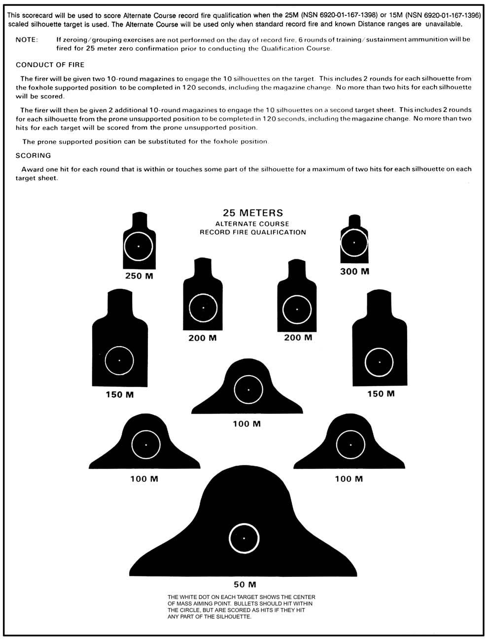
343
RIFLE MARKSMANSHIP M16A1, M16A2/3, M16A4, AND M4 CARBINE
 FM 3-22.9(FM23-9) RIFLE MARKSMANSHIP M16A1, M16A2/3, M16A4, AND M4 CARBINE APRIL 2003 HEADQUARTERS DEPARTMENT OF THE ARMY DISTRIBUTION RESTRICTION: Approved for public release; distribution is unlimited.
RIFLE MARKSMANSHIP M16-/M4-SERIES WEAPONS
 RIFLE MARKSMANSHIP M16-/M4-SERIES WEAPONS FM 3-22.9 August 2008 DISTRIBUTION RESTRICTION: Approved for public release; distribution is unlimited. HEADQUARTERS DEPARTMENT OF THE ARMY *Field Manual No. 3-22.9
RIFLE MARKSMANSHIP M16-/M4-SERIES WEAPONS
 RIFLE MARKSMANSHIP M16-/M4-SERIES WEAPONS FM 3-22.9 August 2008 DISTRIBUTION RESTRICTION: Approved for public release; distribution is unlimited. HEADQUARTERS DEPARTMENT OF THE ARMY This publication is
Small Arms and Crew-Served Weapons Marksmanship Training Strategies Overview
 Small Arms and Crew-Served Weapons Marksmanship Training Strategies Overview 1. Definitions. Webster s dictionary defines a marksman as a person skilled in shooting at a mark or target. However, the intent
M mm Semiautomatic Rifle
 M4-5.56 mm Semiautomatic Rifle What is the FM concerning the M4 Rifle? FM 3-22.9 What is the first thing you should do when you handle a weapon? Make sure you clear it Name the five phases in Basic Rifle
Manual provided by emilitary Manuals-http://www.emilitarymanuals.com OCTOBER 2009
 OCTOBER 2009 This publication is available at Army Knowledge Online (www.us.army.mil) and General Dennis J. Reimer Training and Doctrine Digital Library at (www.train.army.mil). * FM 3-23.30 Field Manual
UNITED STATES MARINE CORPS WEAPONS TRAINING BATTALION MARINE CORPS COMBAT DEVELOPMENT COMMAND QUANTICO, VIRGINIA
 UNITED STATES MARINE CORPS WEAPONS TRAINING BATTALION MARINE CORPS COMBAT DEVELOPMENT COMMAND QUANTICO, VIRGINIA 22134-5040 DETAILED INSTRUCTOR GUIDE LESSON TITLE RIFLE ZEROING COURSE TITLE DIVISION MATCH
Zero an M16A2 Rifle. From Army Manual STP 21-1-SMCT "Soldier's Manual Of Common Tasks"
 Zero an M16A2 Rifle From Army Manual STP 21-1-SMCT "Soldier's Manual Of Common Tasks" *CONDITIONS* On a 25-meter range, given an M16A2 rifle, 18 rounds of 556-mm ammunition, a 300- meter zero target, and
APPENDIX C AND TRAINING
 RANGES APPENDIX C AND TRAINING EXERCISES This appendix provides guidance for US Army machine gun exercises. It is designed to be a working guide for trainers and commanders by explaining range layouts,
UNITED STATES MARINE CORPS WEAPONS TRAINING BATTALION MARINE CORPS COMBAT DEVELOPMENT COMMAND QUANTICO, VIRGINIA
 UNITED STATES MARINE CORPS WEAPONS TRAINING BATTALION MARINE CORPS COMBAT DEVELOPMENT COMMAND QUANTICO, VIRGINIA 134-5040 DETAILED INSTRUCTOR GUIDE LESSON TITLE TABLE COURSE OF FIRE COURSE TITLE DIVISION
RIFLE MARKSMANSHIP M16A1, M16A2/3, M16A4, AND M4 CARBINE
 (FM 23-9) Change 4 Headquarters Department of the Army Washington, DC, 13 September 2006 RIFLE MARKSMANSHIP M16A1, M16A2/3, M16A4, AND M4 CARBINE 1. Change FM 3-22.9(FM 23-9), 24 April 2003, as follows:
UNITED STATES MARINE CORPS WEAPONS TRAINING BATTALION MARINE CORPS COMBAT DEVELOPMENT COMMAND QUANTICO, VIRGINIA
 UNITED STATES MARINE CORPS WEAPONS TRAINING BATTALION MARINE CORPS COMBAT DEVELOPMENT COMMAND QUANTICO, VIRGINIA 22134-5040 DETAILED INSTRUCTOR GUIDE LESSON TITLE KNOWN DISTANCE (KD) COURSE OF FIRE COURSE
UNITED STATES MARINE CORPS WEAPONS TRAINING BATTALION MARINE CORPS COMBAT DEVELOPMENT COMMAND QUANTICO, VIRGINIA
 UNITED STATES MARINE CORPS WEAPONS TRAINING BATTALION MARINE CORPS COMBAT DEVELOPMENT COMMAND QUANTICO, VIRGINIA 22134-5040 DETAILED INSTRUCTOR GUIDE LESSON TITLE DATA BOOK COURSE TITLE ANNUAL RIFLE TRAINING
UNITED STATES MARINE CORPS WEAPONS TRAINING BATTALION MARINE CORPS COMBAT DEVELOPMENT COMMAND QUANTICO, VIRGINIA
 UNITED STATES MARINE CORPS WEAPONS TRAINING BATTALION MARINE CORPS COMBAT DEVELOPMENT COMMAND QUANTICO, VIRGINIA 22134-5040 DETAILED INSTRUCTOR GUIDE LESSON TITLE APPLICATION OF MARKSMANSHIP FUNDAMENTALS
UNITED STATES MARINE CORPS WEAPONS TRAINING BATTALION MARINE CORPS COMBAT DEVELOPMENT COMMAND QUANTICO, VIRGINIA INSTRUCTOR GUIDE
 UNITED STATES MARINE CORPS WEAPONS TRAINING BATTALION MARINE CORPS COMBAT DEVELOPMENT COMMAND QUANTICO, VIRGINIA 22134-5040 INSTRUCTOR GUIDE ZERO A RIFLE COMBAT OPTIC (RCO) TO A SERVICE RIFLE 0300-M16-1005
HEADQUARTERS FM DEPARTMENT OF THE ARMY GRENADES AND PYROTECHNIC SIGNALS
 HEADQUARTERS FM 23-30 DEPARTMENT OF THE ARMY GRENADES AND PYROTECHNIC SIGNALS DISTRIBUTION RESTRICTION: Approved for public release; distribution is unlimited. *FM 3-23-30 (23-30) FIELD MANUAL NO. 3-23.30
UNITED STATES MARINE CORPS WEAPONS TRAINING BATTALION MARINE CORPS COMBAT DEVELOPMENT COMMAND QUANTICO, VIRGINIA
 UNITED STATES MARINE CORPS WEAPONS TRAINING BATTALION MARINE CORPS COMBAT DEVELOPMENT COMMAND QUANTICO, VIRGINIA 22134-5040 DETAILED INSTRUCTOR GUIDE LESSON TITLE RIFLE TABLE 1 COURSE OF FIRE COURSE TITLE
Developing skills requires continued opportunity for instruction, practice, and encouragement.
 Thunder Shooters Club Membership Handbook Developing skills requires continued opportunity for instruction, practice, and encouragement. Introduction... 1 Benefits of Membership... 2 Additional Benefits...
40-mm Grenade Launchers
 TM 3-22.31 (FM 3-22.31) November 2010 40-mm Grenade Launchers Headquarters, Department of the Army DISTRIBUTION RESTRICTION: This publication is approved for public release; distribution is unlimited.
Developing skills requires continued opportunity for instruction, practice, and encouragement.
 Thunder Shooters Club Class Descriptions Developing skills requires continued opportunity for instruction, practice, and encouragement. Introduction... 1 Member Conduct and Responsibilities... 1 Safety...
UNITED STATES MARINE CORPS WEAPONS TRAINING BATTALION MARINE CORPS COMBAT DEVELOPMENT COMMAND QUANTICO, VIRGINIA
 UNITED STATES MARINE CORPS WEAPONS TRAINING BATTALION MARINE CORPS COMBAT DEVELOPMENT COMMAND QUANTICO, VIRGINIA 22134-5040 DETAILED INSTRUCTOR GUIDE LESSON TITLE FIELD FIRING DRY FIRE/SIMULATION EXERCISES
UNITED STATES MARINE CORPS WEAPONS TRAINING BATTALION TRAINING COMMAND GARAND ROAD QUANTICO, VIRGINIA LESSON PLAN
 UNITED STATES MARINE CORPS WEAPONS TRAINING BATTALION TRAINING COMMAND 711 GARAND ROAD QUANTICO, VIRGINIA 134-5036 LESSON PLAN PISTOL FIRING TABLE ONE, TRAINING BLOCKS FOUR AND FIVE SCORING, ALIBI, AND
UNITED STATES MARINE CORPS WEAPONS TRAINING BATTALION TRAINING COMMAND GARAND ROAD QUANTICO, VIRGINIA LESSON PLAN
 UNITED STATES MARINE CORPS WEAPONS TRAINING BATTALION TRAINING COMMAND 27211 GARAND ROAD QUANTICO, VIRGINIA 22134-5036 LESSON PLAN PISTOL TECHNIQUES OF FIRE COMBAT PISTOL PROGRAM CID XXXX REVISED 10/1/2012
CHAPTER 1 INTRODUCTION
 CHAPTER 1 INTRODUCTION The procedures and methods used in Army machine gun marksmanship are based on the concept that soldiers must be skilled gunners who can effectively apply their firing skills in combat.
UNITED STATES MARINE CORPS WEAPONS TRAINING BATTALION MARINE CORPS COMBAT DEVELOPMENT COMMAND QUANTICO, VIRGINIA
 UNITED STATES MARINE CORPS WEAPONS TRAINING BATTALION MARINE CORPS COMBAT DEVELOPMENT COMMAND QUANTICO, VIRGINIA 22134-5040 DETAILED INSTRUCTOR GUIDE LESSON TITLE FUNDAMENTALS OF RIFLE MARKSMANSHIP COURSE
CODE OF MARYLAND REGULATIONS (COMAR) As Amended through January 1, 2013
 As Amended through January 1, 2013") CODE OF MARYLAND REGULATIONS (COMAR) As Amended through January 1, 2013 Title 12 DEPARTMENT OF PUBLIC SAFETY AND CORRECTIONAL SERVICES Subtitle 10 CORRECTIONAL TRAINING COMMISSION Chapter 04 Firearms Training
CODE OF MARYLAND REGULATIONS (COMAR) As Amended through January 1, 2013 Title 12 DEPARTMENT OF PUBLIC SAFETY AND CORRECTIONAL SERVICES Subtitle 10 CORRECTIONAL TRAINING COMMISSION Chapter 04 Firearms Training
HEADQUARTERS DEPARTMENT OF THE ARMY Washington, DC, 17 August 1994 SNIPER TRAINING CONTENTS
 * 17 August 1994 FIELD MANUAL HEADQUARTERS No. 23-10 DEPARTMENT OF THE ARMY Washington, DC, 17 August 1994 SNIPER TRAINING CONTENTS DISTRIBUTION RESTRICTION: Approved for public release; distribution is
CD Compilation Copyright by emilitary Manuals
 * 17 August 1994 FIELD MANUAL HEADQUARTERS No. 23-10 DEPARTMENT OF THE ARMY Washington, DC, 17 August 1994 SNIPER TRAINING CONTENTS DISTRIBUTION RESTRICTION: Approved for public release; distribution is
EXECUTE TABLE 4, ENGAGE THREATS AT UNKNOWN DISTANCES (NIGHT)
") EXECUTE TABLE 4, ENGAGE THREATS AT UNKNOWN DISTANCES (NIGHT) 1 OVERVIEW NIGHT TIME ENGAGEMENTS/ CONSIDERATIONS SUPPORTED POSITIONS (NIGHT) COURSE OF FIRE 2 TERMINAL LEARNING OBJECTIVE Given a service rifle/
EXECUTE TABLE 4, ENGAGE THREATS AT UNKNOWN DISTANCES (NIGHT) 1 OVERVIEW NIGHT TIME ENGAGEMENTS/ CONSIDERATIONS SUPPORTED POSITIONS (NIGHT) COURSE OF FIRE 2 TERMINAL LEARNING OBJECTIVE Given a service rifle/
UNITED STATES MARINE CORPS WEAPONS TRAINING BATTALION MARINE CORPS COMBAT DEVELOPMENT COMMAND QUANTICO, VIRGINIA INSTRUCTOR GUIDE
 UNITED STATES MARINE CORPS WEAPONS TRAINING BATTALION MARINE CORPS COMBAT DEVELOPMENT COMMAND QUANTICO, VIRGINIA 22134-5040 INSTRUCTOR GUIDE EXECUTE TABLE 4, ENGAGE THREATS AT UNKNOWN DISTANCES (NIGHT)
COMMON TRAINING PHASE THREE INSTRUCTIONAL GUIDE SECTION 3 EO C CORRECT MARKSMANSHIP ERROR PREPARATION
 COMMON TRAINING PHASE THREE INSTRUCTIONAL GUIDE SECTION 3 EO C306.02 CORRECT MARKSMANSHIP ERROR Total Time: 60 min PREPARATION PRE-LESSON INSTRUCTIONS Resources needed for the delivery of this lesson are
CHAPTER 2 URBAN ASSAULT COURSE
 CHAPTER 2 URBAN ASSAULT COURSE This chapter describes the Urban Assault Course (UAC), which incorporates doctrine and tactics from FM 90-10-1 and the ARTEP MTPs. The UAC contains five stations: Individual
Preliminary Marksmanship Instruction and Evaluation Rifle and Carbine - M16/M4 Series TC
 Expiration: 30 September 2019 Safe Weapons Handling Rules of Firearms Safety Standardized for any weapon a Soldier may employ Rule 1: Treat every weapon as if it is loaded Rule 2: Never point the weapon
OPERATION AND FUNCTION
 CHAPTER 3 OPERATION AND FUNCTION This chapter discusses the operation of the M249 automatic rifle. This includes loading, unloading, cycle of functioning, adjusting the sight, and using the bipod. 3-1.
40-MM GRENADE LAUNCHER, M203
 HEADQUARTERS FM 3-22.31 (FM 23-31) DEPARTMENT OF THE ARMY 40-MM GRENADE LAUNCHER, M203 FEBRUARY 2003 DISTRIBUTION RESTRICTION: Approved for public release; distribution is unlimited. *FM 3-22.31 (FM 23-31)
MARKSMANSHIP TRAINING
 CHAPTER 5 MARKSMANSHIP TRAINING The procedures, exercises, and techniques for implementing a proper marksmanship program are based on the concept that all machine gunners must understand common firing
UNITED STATES MARINE CORPS WEAPONS TRAINING BATTALION MARINE CORPS COMBAT DEVELOPMENT COMMAND QUANTICO, VIRGINIA
 UNITED STATES MARINE CORPS WEAPONS TRAINING BATTALION MARINE CORPS COMBAT DEVELOPMENT COMMAND QUANTICO, VIRGINIA 22134-5040 DETAILED INSTRUCTOR GUIDE LESSON TITLE PISTOL DIVISION MATCH COURSE OF FIRE COURSE
TRAINING DEVICES AND AIDS
 APPENDIX B TRAINING DEVICES AND AIDS Training devices and training aids enable soldiers to learn as much as they can about a weapon before they try the real thing. This saves money and time, and it prevents
UNITED STATES MARINE CORPS WEAPONS TRAINING BATTALION MARINE CORPS COMBAT DEVELOPMENT COMMAND QUANTICO, VIRGINIA
 UNITED STATES MARINE CORPS WEAPONS TRAINING BATTALION MARINE CORPS COMBAT DEVELOPMENT COMMAND QUANTICO, VIRGINIA 22134-5040 DETAILED INSTRUCTOR GUIDE LESSON TITLE RIFLE AND PISTOL DIVISION MATCH RULES
Preliminary Marksmanship Instruction and Evaluation Grenade Machine Gun - Mk19 Series TC
 Expiration: 30 September 2019 Safe Weapons Handling Rules of Firearms Safety Standardized for any weapon a Soldier may employ Rule 1: Treat every weapon as if it is loaded Rule 2: Never point the weapon
CHECK OUT OUR WEBSITE SOME TIME FOR PLENTY OF ARTICES ABOUT SELF DEFENSE, SURVIVAL, FIREARMS AND MILITARY MANUALS.
 CHECK OUT OUR WEBSITE SOME TIME FOR PLENTY OF ARTICES ABOUT SELF DEFENSE, SURVIVAL, FIREARMS AND MILITARY MANUALS. http://www.survivalebooks.com/ Thank you for purchasing our ebook package. *TB 9-1000-237-12
UNITED STATES MARINE CORPS WEAPONS TRAINING BATTALION MARINE CORPS COMBAT DEVELOPMENT COMMAND QUANTICO, VIRGINIA INSTRUCTOR GUIDE
 UNITED STATES MARINE CORPS WEAPONS TRAINING BATTALION MARINE CORPS COMBAT DEVELOPMENT COMMAND QUANTICO, VIRGINIA 22134-5040 INSTRUCTOR GUIDE CORRECTIVE ACTION WITH A SERVICE RIFLE 0300-M16-1003 0300-M16-1017
Engage Targets with an M16-Series Rifle
 Engage Targets with an M16-Series Rifle 071-311-2007 Conditions: Given an M16-series rifle, magazines, ammunition, individual combat equipment, and stationary or moving targets (personnel or equipment)
COMMON TRAINING PHASE ONE INSTRUCTIONAL GUIDE SECTION 1 EO M IDENTIFY THE PARTS AND CHARACTERISTICS OF THE DAISY 853C AIR RIFLE PREPARATION
 COMMON TRAINING PHASE ONE INSTRUCTIONAL GUIDE SECTION 1 EO M106.01 IDENTIFY THE PARTS AND CHARACTERISTICS OF THE DAISY 853C AIR RIFLE Total Time: 30 min PREPARATION PRE-LESSON INSTRUCTIONS A complete list
Field Firing for the M16A2 Rifle
 FMFM 0-9 Field Firing for the M16A2 Rifle U.S. Marine Corps PCN 139 000024 00 FMFM 0-9 FIELD FIRING FOR THE M16A2 RIFLE FMFM 0-9 Record of Changes Change No. Date of Change Date of Entry Organization
UNITED STATES MARINE CORPS WEAPONS TRAINING BATTALION MARINE CORPS COMBAT DEVELOPMENT COMMAND QUANTICO, VIRGINIA
 UNITED STATES MARINE CORPS WEAPONS TRAINING BATTALION MARINE CORPS COMBAT DEVELOPMENT COMMAND QUANTICO, VIRGINIA 22134-5040 DETAILED INSTRUCTOR GUIDE LESSON TITLE FUNDAMENTALS OF RIFLE MARKSMANSHIP COURSE
UNITED STATES MARINE CORPS WEAPONS TRAINING BATTALION TRAINING COMMAND GARAND ROAD QUANTICO, VIRGINIA LESSON PLAN
 UNITED STATES MARINE CORPS WEAPONS TRAINING BATTALION TRAINING COMMAND 27211 GARAND ROAD QUANTICO, VIRGINIA 22134-5036 CPP.8 LESSON PLAN PISTOL PRESENTATION AND SEARCH AND ASSESS CPP.8 COMBAT PISTOL PROGRAM
COMMON TRAINING INSTRUCTIONAL GUIDE SECTION 4 EO C PRACTICE FIRING TECHNIQUES PREPARATION
 COMMON TRAINING INSTRUCTIONAL GUIDE SECTION 4 EO C206.03 PRACTICE FIRING TECHNIQUES Total Time: 30 min PREPARATION PRE-LESSON INSTRUCTIONS Resources needed for the delivery of this lesson are listed in
COMMON TRAINING PHASE ONE INSTRUCTIONAL GUIDE SECTION 4 EO M FOLLOW RULES AND COMMANDS ON AN AIR RIFLE RANGE PREPARATION
 COMMON TRAINING PHASE ONE INSTRUCTIONAL GUIDE SECTION 4 EO M106.04 FOLLOW RULES AND COMMANDS ON AN AIR RIFLE RANGE Total Time: 30 min PREPARATION PRE-LESSON INSTRUCTIONS A complete list of resources needed
Supressors, Evolving to an Integrated Unit. Designing with the Soldier in mind
 Supressors, Evolving to an Integrated Unit Designing with the Soldier in mind Sophia Tassy Small & Medium Cal. Weapons Systems Div. US ARMY Picatinny Arsenal, NJ 07806 973-724-3121 Briefing Objectives
Summary Report for Individual Task M-1650 Operate Vehicle Using Drivers Vision Enhancer Status: Approved
 Report Date: 05 Dec 2014 Summary Report for Individual Task 551-88M-1650 Operate Vehicle Using Drivers Vision Enhancer Status: Approved Distribution Restriction: Approved for public release; distribution
BY ORDER OF THE SECRETARY OF THE AIR FORCE. AIR FORCE MANUAL , VOLUME 2 1 February Personnel
 BY ORDER OF THE SECRETARY OF THE AIR FORCE AIR FORCE MANUAL 36-2227, VOLUME 2 1 February 1996 Personnel COMBAT ARMS TRAINING AND MAINTENANCE RIFLE, HANDGUN, SHOTGUN, GRENADE LAUNCHER, M72 LIGHT ANTITANK
TEACHING MARKSMANSHIP TO CADETS. JROTC Marksmanship Instructor Course, Section VI
 TEACHING MARKSMANSHIP TO CADETS JROTC Marksmanship Instructor Course, Section VI Teaching Marksmanship to Cadets (Coaching New Shooters) Section Objective: To review principles and guidelines for teaching
Pistol TC Headquarters, Department of the Army
 TC 3-23.35 Pistol 2017 DISTRIBUTION RESTRICTION: Approved for public release; distribution is unlimited. This publication supersedes FM 3-23.35 (Combat Training with Pistols, M9 and M11), 25 June 2003.
LESSON 5: AIMING AND FIRING
 LESSON 5: AIMING AND FIRING enough to fire all shots within the scoring rings of the official competition target. PURPOSE This lesson introduces you to the basic techniques for firing an aimed shot, at
Kamloops Target Sports Association. Range Officer Training Course 2007
 Kamloops Target Sports Association Range Officer Training Course 2007 1 KTSA Range Safety Officer Course LESSON I: Welcome OBJECTIVES Understand the purpose of the RSO Course Explain procedures for becoming
CHAPTER 2 MARKSMANSHIP TRAINING Section I. BASIC MARKSMANSHIP
 CHAPTER 2 MARKSMANSHIP TRAINING Section I. BASIC MARKSMANSHIP 2-1. PHASES OF TRAINING Marksmanship training is divided into two phases: preparatory marksmanship training and range firing. Each phase may
Modern Army Combatives Program Competitions
 Modern Army Combatives Program Competitions Competition: The act of striving against another force for the purpose of achieving dominance or out of a biological imperative such as survival. AGENDA Why
Employ The Risk Management Process During Mission Planning
 Employ The Risk Management Process During Mission Planning TSG 154-6465 Task(s) TASK NUMBER TASK TITLE Taught or 154-385-6465 Employ The Risk Management Process During Mission Planning Supported Task(s)
APPENDIX B AIDS AND DEVICES
 APPENDIX B TRAINING AIDS AND DEVICES The use of devices in marksmanship training programs are important factors because they may allow the gunner to get an idea of what actual combat is like. The training
LESSON 5: AIMING AND FIRING
 LESSON 5: AIMING AND FIRING PURPOSE appropriate for new shooters who have not yet developed the ability to hold the rifle steady enough to fire all shots within the scoring rings of the official competition
Appendix 5 NRA INSTRUCTOR TRAINING PROGRAM PRE-COURSE QUALIFICATION PISTOL
 NRA TRAINING COUNSELOR GUIDE Appendix 5: NRA Instructor Training Program Pre-Course Qualification Pistol Appendix 5 NRA INSTRUCTOR TRAINING PROGRAM PRE-COURSE QUALIFICATION PISTOL The NRA Instructor Training
A-CR-CCP-701/PF-001 CHAPTER 6 PO 106 FIRE THE CADET AIR RIFLE
 CHAPTER 6 PO 106 FIRE THE CADET AIR RIFLE COMMON TRAINING INSTRUCTIONAL GUIDE SECTION 1 EO M106.01 IDENTIFY THE PARTS AND THE CHARACTERISTICS OF THE DAISY 853C AIR RIFLE Total Time: 30 min INTRODUCTION
The shotgun is the most misunderstood
 THE COMBAT SHOTGUN IN THE BCT FIRST SERGEANT (RETIRED) D. ROBERT CLEMENTS The shotgun is the most misunderstood weapon in the Brigade Combat Team. The combat shotgun has found new life in the Infantry
UNITED STATES MARINE CORPS WEAPONS TRAINING BATTALION MARINE CORPS COMBAT DEVELOPMENT COMMAND QUANTICO, VIRGINIA
 UNITED STATES MARINE CORPS WEAPONS TRAINING BATTALION MARINE CORPS COMBAT DEVELOPMENT COMMAND QUANTICO, VIRGINIA 22134-5040 DETAILED INSTRUCTOR GUIDE LESSON TITLE WEAPONS HANDLING - M16A2 SERVICE RIFLE
40-MM GRENADE LAUNCHER, M79
 APPENDIX A 40-MM GRENADE LAUNCHER, M79 This appendix provides guidance for US Army units to conduct training with the M79 grenade launcher. The weapon s characteristics, disassembly and assembly procedures,
FIREARMS TRAINING. Firearms Intermediate Level
 FIREARMS TRAINING Firearms Intermediate Level 1 Background The intermediate firearms module develops the officers basic skills training them to use cover and tactical movement as part of their training.
SAFETY SUMMARY.2 CHAPTER I - INTRODUCTION.5 CHAPTER II - OPERATING INSTRUCTIONS.12 CHAPTER III - CALCULATING OFFSET FOR SIGHT ALIGNMENT.
 Technical Manual TABLE OF CONTENTS Page SAFETY SUMMARY...2 CHAPTER I - INTRODUCTION...5 CHAPTER II - OPERATING INSTRUCTIONS...12 CHAPTER III - CALCULATING OFFSET FOR SIGHT ALIGNMENT...19 CHAPTER IV - TROUBLESHOOTING...27
FM INDEX Index-1
 INDEX adjustment of fire, 6-13, 6-14, 6-24, 6-42, 6-46 AE (angle of elevation). See angle of elevation aiming-point method, 6-37 (illus), 6-41, 6-42 (illus) aiming-stake method, 6-38 ammunition, 1-9 (illus),
XM8 US M4 System Comparison
 XM8 US M4 System Comparison HECKLER & KOCH DEFENSE Inc. System Weight: Overall Length: XM8 Lightweight Modular Weapon System (includes integrated sight with IR laser & illuminator, red dot reflex sight,
The United States Armed Forces is the main line of defense to protect our country
 The United States Armed Forces is the main line of defense to protect our country from the threats of the world. If the armed forces are not well equipped, our soldiers can not fight and protect their
Training and Evaluation Outline Report
 Training and Evaluation Outline Report Status: Approved 12 Nov 2014 Effective Date: 20 Jul 2017 Task Number: 05-PLT-5504 Task Title: Inspect Underwater Structures Distribution Restriction: Approved for
COMMON TRAINING PHASE ONE INSTRUCTIONAL GUIDE SECTION 2 EO M CARRY OUT SAFETY PRECAUTIONS ON THE CADET AIR RIFLE PREPARATION
 COMMON TRAINING PHASE ONE INSTRUCTIONAL GUIDE SECTION 2 EO M106.02 CARRY OUT SAFETY PRECAUTIONS ON THE CADET AIR RIFLE Total Time: 30 min PREPARATION PRE-LESSON INSTRUCTIONS A complete list of resources
APPENDIX P Saber Challenge Course: A True Stress Inoculation Training Program 1
 APPENDIX P Saber Challenge Course: A True Stress Inoculation Training Program 1 The Saber Challenge Course being conducted on outdoor range. Instructor #1 (foreground) fires Simunition FX Marking Cartridges
TM WARNING SUMMARY
 TM 9-005-239-0 WARNING SUMMARY Treat every firearm as if it were loaded. Never accept or take over a firearm from another until you have checked personally to see that it is unloaded or in a completely
UNITED STATES MARINE CORPS WEAPONS TRAINING BATTALION MARINE CORPS COMBAT DEVELOPMENT COMMAND QUANTICO, VIRGINIA
 UNITED STATES MARINE CORPS WEAPONS TRAINING BATTALION MARINE CORPS COMBAT DEVELOPMENT COMMAND QUANTICO, VIRGINIA 22134-5040 DETAILED INSTRUCTOR GUIDE LESSON TITLE RIFLE RELOADS COURSE TITLE DIVISION MATCH
MARKSMANSHIP CHECK CARD
 MARKSMANSHIP CHECK CARD Every Marine can learn to be an expert shot. To be one, however, you must first learn thoroughly the principles and techniques of marksmanship and then apply them in a confident
UNITED STATES MARINE CORPS WEAPONS TRAINING BATTALION TRAINING COMMAND GARAND ROAD QUANTICO, VIRGINIA LESSON PLAN
 UNITED STATES MARINE CORPS WEAPONS TRAINING BATTALION TRAINING COMMAND 711 GARAND ROAD QUANTICO, VIRGINIA 134-5036 LESSON PLAN TABLE ONE TRAINING BLOCK THREE COMBAT PISTOL PROGRAM CID XXXX REVISED 10/1/01
UNITED STATES MARINE CORPS WEAPONS TRAINING BATTALION MARINE CORPS COMBAT DEVELOPMENT COMMAND QUANTICO, VIRGINIA
 UNITED STATES MARINE CORPS WEAPONS TRAINING BATTALION MARINE CORPS COMBAT DEVELOPMENT COMMAND QUANTICO, VIRGINIA 22134-5040 DETAILED INSTRUCTOR GUIDE LESSON TITLE EFFECTS OF WEATHER COURSE TITLE DIVISION
1 P a g e. Royal Canadian Sea Cadet Corps Centurion Marksmanship
 1 P a g e Royal Canadian Sea Cadet Corps Centurion Marksmanship 2 P a g e Marksmanship Manual Marksmanship training involves learning to fire the cadet air rifle. You will be taught many lessons about
UNITED STATES MARINE CORPS WEAPONS TRAINING BATTALION MARINE CORPS COMBAT DEVELOPMENT COMMAND QUANTICO, VIRGINIA INSTRUCTOR GUIDE
 UNITED STATES MARINE CORPS WEAPONS TRAINING BATTALION MARINE CORPS COMBAT DEVELOPMENT COMMAND QUANTICO, VIRGINIA 22134-5040 INSTRUCTOR GUIDE ENGAGE MOVING THREATS 0300-M16-1017 0300-M16-1017 (REV.) MODIFIED
Chapter 2 Technique of Fire Section 1. Introduction
 0 0 0. General Chapter Technique of Fire Section. Introduction When squad members have completed individual marksmanship training, and before they commence combat firing in tactical problems, they must
COMMON TRAINING INSTRUCTIONAL GUIDE SECTION 3 EO C PRACTICE AIMING TECHNIQUES PREPARATION
 COMMON TRAINING INSTRUCTIONAL GUIDE SECTION 3 EO C206.02 PRACTICE AIMING TECHNIQUES Total Time: 60 min PREPARATION PRE-LESSON INSTRUCTIONS Resources needed for the delivery of this lesson are listed in
If you do not understand any of the material in this manual or have any questions, contact the Product Service Center or a qualified gunsmith.
 Bolt Action Rifle Patent No. 7823315 B2 and Patents Pending Note: This manual is only a supplement to your firearm s owner s manual. It only addresses the FLEX System and its accessories. IMPORTANT SAFETY
Basic Shooting Skills Principles of Marksmanship. By: Shannon Carlton
 Basic Shooting Skills Principles of Marksmanship By: Shannon Carlton Agenda Introduction Principles of Coaching 5 Principles of Marksmanship Developing a Routine Making Sight Adjustments Sequences Principles
UNITED STATES MARINE CORPS WEAPONS TRAINING BATTALION TRAINING COMMAND GARAND ROAD QUANTICO, VIRGINIA LESSON PLAN
 UNITED STATES MARINE CORPS WEAPONS TRAINING BATTALION TRAINING COMMAND 711 GARAND ROAD QUANTICO, VIRGINIA 134-5036 LESSON PLAN PISTOL FIRING TABLE ONE - TRAINING BLOCK TWO COMBAT PISTOL PROGRAM CID XXXX
INFORMATION SHEET BEFORE YOU START... Application to Register Firearms (for Individuals) A - TYPE OF ACQUISITION
 A - TYPE OF ACQUISITION") INFORMATION SHEET Application to Register Firearms (for Individuals) BEFORE YOU START... USE THIS FORM to apply to register all non-restricted and restricted firearms you have newly imported or acquired
INFORMATION SHEET Application to Register Firearms (for Individuals) BEFORE YOU START... USE THIS FORM to apply to register all non-restricted and restricted firearms you have newly imported or acquired
PISTOL NRA Instructor Candidate Training Packet
 7457 Williamson Lane Canal Winchester, OH 43110 www.armed2defend.com 614-503-5214 PISTOL NRA Instructor Candidate Training Packet Armed2Defend LLC Version 08172017 Instructor Candidate s Name: Instructor
DANGER WARNING CAUTION
 Report Date: 13 Mar 2015 Summary Report for Crew Drill Drill Task Drill Number: 07-4-D9267 Drill Title: Place 81-mm Mortar into Action Status: Approved Status Date: 13 Mar 2015 Distribution Restriction:
BROWNING AUTOMATIC RIFLE, CALIBER.30, M1918A2 WITH BIPOD
 FM 23-15 WAR DEPARTMENT BASIC FIELD MANUAL BROWNING AUTOMATIC RIFLE, CALIBER.30, M1918A2 WITH BIPOD L -~~~~~~~~~~~~~~~~~~~~~~~~ FM 23-15 BASIC FIELD MANUAL BROWNING AUTOMATIC RIFLE CALIBER.30, M1918A2
Training and Evaluation Outline Report
 Training and Evaluation Outline Report Status: Approved 27 Mar 2015 Effective Date: 14 Jul 2017 Task Number: 05-TM-5520 Task Title: Perform Emergency Medical Treatment for Diving Disorders Not Requiring
CHAPTER 6 PO 106 FIRE THE CADET AIR RIFLE
 CHAPTER 6 PO 106 FIRE THE CADET AIR RIFLE 6-106-1/2 COMMON TRAINING PROFICIENCY LEVEL ONE INSTRUCTIONAL GUIDE SECTION 1 EO M106.01 IDENTIFY THE PARTS AND THE CHARACTERISTICS OF THE DAISY 853C AIR RIFLE
CHAPTER 1. DESCRIPTION AND COMPONENTS This chapter describes the weapon and the types of ammunition in detail and provides a table of general data.
 CHAPTER 1 DESCRIPTION AND COMPONENTS This chapter describes the weapon and the types of ammunition in detail and provides a table of general data. 1-1. DESCRIPTION The M249 AR is a gas-operated, air-cooled,
WEAPONS INSPECTION SEMI-AUTOMATIC. The instructors will inspect each shooter's weapon prior to any firing.
 WEAPONS INSPECTION SEMI-AUTOMATIC The instructors will inspect each shooter's weapon prior to any firing. a. Ensure that all weapons and magazines are cleared of rounds. Check it again. b. Check the BARREL.
Precision Rifle I. Practice doesn t make perfect. Perfect practice makes perfect. Controlled Chaos Arms. Precision Rifle 1 Course
 Precision Rifle 1 Course October 01-02 2011, 8AM 5 PM Location: Big Springs Range Complex Searsboro, IA Cost: $500 Topics covered: Day One Safety brief Basic shooting terminology used precision shooting-
RECRUIT SUSTAINMENT PROGRAM SOLDIER TRAINING READINESS MODULES Drill and Ceremony Overview 1 September 2012
 RECRUIT SUSTAINMENT PROGRAM SOLDIER TRAINING READINESS MODULES Drill and Ceremony Overview 1 September 2012 SECTION I. Lesson Plan Series Task(s) Taught Academic Hours References Student Study Assignments
Modern Army Combatives Program Duties and Responsibilities
 Modern Army Combatives Program Duties and Responsibilities 1 Four levels of Instructor Certification: Basic Combatives Course (Level I) 40 hrs Basic level Instructors Teach Level I Techniques Train the
FM PREFACE Unless this publication states otherwise, masculine nouns and pronouns do not refer exclusively to men.
 PREFACE This manual is intended to provide technical information, training techniques, and guidance on the Browning machine gun caliber.50 HB, M2. Unit leaders and the designated gunners will find this
PROFICIENCY (PERFORMANCE) EXAMINATION
 EXAMINATION") APPENDIX C PROFICIENCY (PERFORMANCE) EXAMINATION This appendix provides the examination used to test grenadier proficiency in dry-fire tasks. C-1. DESCRIPTION The examination is a practical nonfiring exercise
APPENDIX C PROFICIENCY (PERFORMANCE) EXAMINATION This appendix provides the examination used to test grenadier proficiency in dry-fire tasks. C-1. DESCRIPTION The examination is a practical nonfiring exercise
It feels easy, and it should. Well, what you learn is it is! And in the process, I dreamed up a drill that mimics a game that s fun too.
 Easy Clean Target Drill. I ll take a 25 yard sustained fire target and across the top list the numbers 1, 2, 3, and so on until I get to 6. My long term goal is to shoot 6 consecutive clean sustained fire