OWNER'S MANUAL LOCK-N-LOAD BULLET FEEDER (PISTOL)
|
|
|
- Madison Shaw
- 6 years ago
- Views:
Transcription


1 OWNER'S MANUAL LOCK-N-LOAD BULLET FEEDER (PISTOL)

2 Table of Contents ASSEMBLY ASSEMBLY Pistol Bullet Feeder... Page 3 CHANGE-OVERS The Hornady Lock-N-Load Pistol Bullet Feeder is capable of feeding most pistol bullets. Refer to this section when changing bullet caliber, type, or brand. Pistol Bullet Feeder... Page 11 Plate Height Wiper Adjustment Drop Tube Funnel Drop Tube Bullet Feed Die APPENDIX APPENDIX B Lock-N-Load AP Press Mounting Template... Page ASSEMBLY: PISTOL BULLET FEEDER
 and spread them over a large flat surface.")

3 Lock-N-Load AP Pistol Bullet Feeder OVERVIEW Your new Lock-N-Load AP Pistol Bullet Feeder has been packaged to ensure minimal vibration and damage during transportation. Remove all the parts from the packing box (see page 2) and spread them over a large flat surface. Refer to the parts list and exploded view on the next two pages and check to make sure all necessary parts are identified. This manual provides step-by-step instructions that make set-up and operation easy and understandable. ASSEMBLY Tools needed for assembly and set-up: 7/16" End Wrench 3/16" Hex Wrench 1/4" Drill Bit Electric Drill ASSEMBLY: PISTOL BULLET FEEDER - 3 -
4 ASSEMBLY Lock-N-Load Auto Progressive (AP ) Pistol Bullet Feeder PARTS LIST Item No. Production Part No. Qty. Description Nut Hex Zinc Item No. Production Part No. Qty. Description Spur Gear P.D. 24 Tooth Steel Knurled Thumb Screw Tube Spring Clamp BHCS X 1/ Tube Bullet Drop Funnel Large Tube Bullet Drop Funnel Medium Tube Bullet Drop Funnel Small Screw Adjustment Bullet Feed Screw Lock Nut Adjustment Rubber Washer Flat Center Plate Adjustment Nut Thumb Screw 1/4-20 X 1/ Hopper Turning Plate Screw FHSCS X 1/ Bullet Feed Wheel - Pistol Nut Hex 1/ Center Pin Bullet Plate Spur Gear P.D., 30 Tooth Screw FHSCS X 3/ Bullet Feeder Base Plate Ideler Gear Shaft FHCS 1/4-20 X 1/ Pin Spirol 1/8 X 3/ Motor Bullet Feeder Screw Bullet Wiper Nut Wing 1/ Spring Wiper Bullet Feed Thumb Screw 8-32 X 1/ Tube Holder Bullet Feeder Bullet Feed Hopper SHCS 1/4-20 X Washer Flat 1/4" Bushing (HEYCO 1147) Black Tube Drop Small Tube Drop Medium Tube Drop Large Switch 2 Position Support Tube-Bottom Support Tube-Top " Square Finishing Plug /4-20x2.5 Carriage Bolt ASSEMBLY: PISTOL BULLET FEEDER
5 Lock-N-Load AP Pistol Bullet Feeder EXPLODED VIEW ASSEMBLY ASSEMBLY: PISTOL BULLET FEEDER - 5 -

 is securely attached to the bench top, line up the Support Tube-Top on the front of the tube, oriented as shown in the exploded view on page 27. Slide a ¼-20x2.")
6 ASSEMBLY 1 Mounting the Bullet Feeder to the Bench Refer to Appendix B for the template. Place the template on the table in the location you would like to mount the press and Lock-N-Load AP Pistol Bullet Feeder. Drill ¼" holes for the placement of the Square Tubing Mounting Bracket. 1 2 Use ¼" bolts with ¼" Flat Washers (not provided, due to different thicknesses of tables) on top of the Square Tubing Mounting Bracket and also one on the bottom of the bench. 2 3 Once the Support Tube-Bottom (36) is securely attached to the bench top, line up the Support Tube-Top on the front of the tube, oriented as shown in the exploded view on page 27. Slide a ¼-20x2.5 Carriage Bolt (39) through one of the square holes in the top tube and through the slot in the bottom tube. Place a ¼ Flat Washer (31) over the bolt and thread on a ¼-20 Wing Nut (25). Repeat with another bolt, washer, and nut through the other square hole. The height of this tube may need to be adjusted at a later time in order to allow bullets to slide freely down the Drop Tube (33) ASSEMBLY: PISTOL BULLET FEEDER
, with the open face of the Hopper facing the front of the bench or table.")


7 Mounting the Bullet Feed Hopper to the Square Tubing Mounting Bracket 4 4 Slide the Hopper (29) over the top of the Square Tubing Mounting Bracket (37), with the open face of the Hopper facing the front of the bench or table. ASSEMBLY Square Tubing Bracket 5 Place a ¼-20 X 2 SHCS Bolt (30) with one ¼" Flat Washer (31) through the top hole of the Bullet Feed Hopper and the Square Tubing Bracket. 5 SHCS Bolt Flat Washer 6 Place a ¼-20 X 2 SHCS Bolt (30) with one ¼" Flat Washer (31) through the bottom hole of the Bullet Feed Hopper and the Square Tubing Mounting Bracket. 6 If you are having issues with bullets not being able to keep up feeding (approximately 100 bullets in 5 to 6 minutes), switch the bolt from the bottom hole to the middle hole. SHCS Bolt Flat Washer ASSEMBLY: PISTOL BULLET FEEDER - 7 -

 onto the two ¼-20 X 2 SHCS Bolts and tighten")
.")
8 ASSEMBLY 7 Place a ¼" Flat Washer (31) over the end of each of the two Bolts just previously place through the Bullet Feed Hopper and Square Tubing Mounting Bracket. Place a ¼-20 Hex Nut (14) onto the two ¼-20 X 2 SHCS Bolts and tighten snug. 7 Tighten Hex Nut 8 Bullet Feed Hopper Set Up Loosen ¼-20 Thumb Screw (10). 8 Thumb Screw 9 Loosen Lock Nut (7) on the Adjustment Screw (6). 9 Adjustment Screw Lock Nut ASSEMBLY: PISTOL BULLET FEEDER


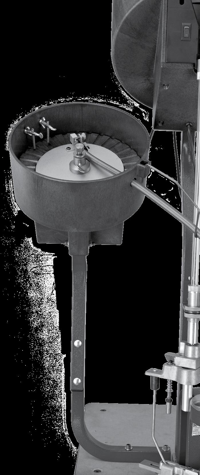
9 10 Bullet Feed Hopper Set Up (con't) Raise the Hopper Turning Plate (11) by turning the Adjustment Screw (6) clockwise. Raise the Bullet Guide Plate above the bottom of the slots on the Bullet Feed Wheel Pistol far enough to hold a bullet base first against the Bullet Feed Wheel Pistol. 10 ASSEMBLY Adjustment Screw Hopper Turning Plate 11 Place a bullet that you plan on loading facing base first up against the Bullet Guide Plate and against the Bullet Feed Wheel Pistol. Next to this bullet, place another bullet so that the nose is facing the center of the Bullet Feed Wheel Pistol. You will then need to adjust the Bullet Guide Plate either up or down to get a bullet to stay on the Bullet Feed Wheel Pistol base first, but fall off the Bullet Feed Wheel Pistol if the bullet is nose first towards center of the Bullet Feed Wheel Pistol. 11 Bullet Feed Wheel Pistol Bullet Guide Plate 12 Bullet Wiper (Bottom Wiper) Install the wipers as with one Wing Nut (25) installed on the outside of the Bullet Feed Hopper on the Wiper Screw (24). Loosen the wing nuts. 12 Hopper Wiper Screw Wing Nuts Wiper Spring Place two bullets nose to nose in a slot close to the height of the first or bottom wiper screw and Wiper Spring (26). Adjust the first wiper spring and screw to wipe off the outside bullet. Tighten down the two wing nuts and the thumb screw. ASSEMBLY: PISTOL BULLET FEEDER - 9 -


...Item No. 399214 14 15 Insert the Drop Funnel (5) into Tube Spring Clamp (3).")
10 Bullet Wiper (Top Wiper) 13 Wing Nuts ASSEMBLY 13 Install the wipers as shown in with one Wing Nut installed on the outside of the Bullet Feed Hopper) on the Wiper Screw. Place one bullet facing the center of the Bullet Feed Wheel Pistol base first. Next to it, place a bullet facing nose first to the center of Bullet Feed Wheel Pistol. The bullet that is facing nose first, push the nose down a little so the base is sticking up. Wiper Screw Wiper Spring Thumb Screw Adjust the second Wiper Spring and Wiper Screw to just miss the nose of the first bullet but kick the base of the second bullet. Tighten down the two Wing Nuts and the Thumb Screw. 14 Drop Funnel Select the correct size of Drop Funnel for your application. 9MM/38/ (375 I.D.)...Item No S&W/10 MM...(406 I.D.)...Item No /.451/ (530 I.D.)...Item No Insert the Drop Funnel (5) into Tube Spring Clamp (3). You will want the front edge (outside edge) of the Drop Funnel as close to the Bullet Feed Wheel Pistol without touching the Bullet Feed Wheel Pistol. 15 Bullet Feed Wheel Pistol Tighten the Knurled Thumb Screw (2) on the side of the Tube Spring Clamp. Only snug this screw, DO NOT over tighten this screw. Knurled Thumb Screw Tube Spring Clamp Drop Funnel ASSEMBLY: PISTOL BULLET FEEDER


11 Setup / Changeover of the Lock-N-Load Pistol Bullet Feeder The Hornady Lock-N-Load Pistol Bullet Feeder is capable of feeding most pistol bullets. When changing bullet caliber, type, or brand, the following components on the Bullet Feeder may need to be changed or verified. Hopper Plate Height. Bottom Wiper Location 1 Top Wiper Location Drop Tube Funnel Drop Tube Bullet Feeder Dies 1 Hopper Plate Height Loosen ¼-20 Thumb Screw and the Lock Nut on the Adjustment Screw. Raise the Bullet Guide Plate by turning the Adjustment Screw clockwise. Raise the Bullet Guide Plate above the bottom of the slots on the Bullet Feed Wheel Pistol far enough to hold a bullet base first against the Bullet Feed Wheel Pistol. Place two bullets onto the Bullet Feed Wheel, one with the nose toward the center, and the other with the base toward the center. Rotate the Adjustment Screw to adjust the Bullet Guide Plate either up or down to get a the nose down bullet to fall off the plate, yet keep the base down bullet on the Bullet Guide Plate. Once the Bullet Guide Plate position is acceptable, tighten the Lock Nut and then the ¼-20 Thumb Screw. Adjustment Screw 2 2 Thumb Screw Bullet Feed Wheel Lock Nut CHANGE-OVER 3 Adjusting the Bottom Wiper The bottom wiper is used to remove the top bullet when two bullets are double-stacked on the Feed Wheel Plate. To adjust the spring location, loosen the two Wing Nuts and slide the assembly in or out. The spring should be located so the top bullet is knocked off the bottom bullet as the Bullet Feed Wheel turns. Tighten down the two wing nuts and the thumb screw. Loosen the thumb screw and move the spring so that it just clears the Bullet Feed Wheel. The spring should not contact the Feed Wheel Plate during normal operation. With a little trial and error, the spring should be adjusted so that it knocks off the top bullet without disturbing the bottom bullet. 3 Wing Nut Wing Nut Thumb Screw CHANGE-OVER: PISTOL BULLET FEEDER


...Item No. 399215.44/.451/.452... (530 I.D.)...Item No. 399214 Insert the Drop Funnel into Tube Spring Clamp.")

12 4 Adjusting the Top Wiper The Top Wiper is intended to remove nose heavy bullets that do not fall off when pointed nose down on the Bullet Feed Plate. Place two bullets onto the Bullet Feed Wheel near the Top Wiper, one with the nose toward the center, and the other with the base toward the center. Push the nose down a little on the bullet that is nose toward so the base is sticking up. Adjust the second wiper spring and wiper screw to just miss the nose of the first bullet but kick the base of the second bullet. Tighten down the two wing nuts and the thumb screw. 4 Wing Nut Wiper Screw Thumb Screw Wiper Spring 5 Switching Drop Tube Funnel Select the correct size of Drop Funnel for your application. 9MM/38/ (375 I.D.)...Item No S&W/10 MM... (406 I.D.)...Item No /.451/ (530 I.D.)...Item No Insert the Drop Funnel into Tube Spring Clamp. You will want the front edge (outside edge) of the Drop Funnel as close to the Bullet Feed Wheel Pistol without touching the Bullet Feed Wheel Pistol. Tighten the Knurled Thumb Screw on the side of the Tube Spring Clamp. Only snug this screw, DO NOT over tighten this screw. 5 Tube Spring Clamp Knurled Thumb Screw Drop Tube Funnel 6 Switching the Drop Tube Select the correct size of Drop Tube for your application. 9MM/38/ (375 I.D.)...Item No S&W... (406 I.D.)...Item No /.451/ (530 I.D.)...Item No Slip the Drop Tube into the hole on the bottom right side of the Bullet Feed Hopper. Insert the end of the Drop Tube into the back end of the Drop Funnel. Insert the straight end of the Drop Tube Holder into the hole on the bottom right side of the hopper. Next place the Drop Tube into the hook of Drop Tube Holder. CHANGE-OVER 6 Drop Tube Funnel 7 Testing Hopper Setup At this time, place about 100 bullets into the Bullet Feed Hopper and turn on the Switch on the bottom right corner of the Bullet Feed Hopper. You will want to hold the end of the Drop Tube in your hand at this time to catch the bullets that will fall out of the tube. At this time, make sure you have the Bullet Wipers set correctly. If they are not, shut off the Switch and readjust the Bullet Wipers. You may need to do this a couple of times, until you have them set correctly and the bullets are falling base first every time. If the hopper plate is jumping or not rotating smoothly, your Drop Tube Funnel is too close to the Bullet Feed Wheel Pistol. This needs backed off until the Bullet Feed Wheel Pistol rotates smoothly. If the bullets are feeding correctly, tighten down the Bullet Guide Plate Thumb Screw, and Snug Lock Nut. Drop Tube 7 Drop Tube Funnel Drop Tube CHANGE-OVER: PISTOL BULLET FEEDER

13 Bullet Feed Die Set Up Disassemble the die and lay the parts out on a flat surface. Degrease every part of the die. Reassemble the die as you took it apart. Collet A goes in first with the open slots facing the bottom of the die. Collet B goes in next with the open slots facing the bottom of the die. Thread the Lock Ring back onto the Adjustment Screw until the Lock Ring is near the top end of the Adjustment Screw. Place the O-Ring over the threads of the Adjustment Screw until it is close to the Lock Ring. Screw the Adjustment Screw into the die. Screw it down until the end of the Adjustment Screw is just touching Collet B. With the Adjustment Screw touching the top Collet, back the Adjustment Screw off ½ turn and lock down the Lock Ring against the top of the Die Body. At this time you should be able to shake the die and hear the two Collets move up and down just a little bit. If you hear this, the die is set up correctly. Die Adjustment Lock-N-Load AP Screw on the Lock Ring to the outside threads of the Die Body. Adjustment Screw Lock Ring O-Ring Collet B Collet A Screw on the Lock-N-Load Bushing to the outside threads of the Die Body. Place the die into the top of the press and inserting it into the Lock-N-Load Bushing in the Press Body. Die Adjustment for a NON Lock-N-Load AP Place a Flared Case for your set up in the previous station. Case mouths should be flared to the approximate dimensions listed below. 380/9MM " 38/ " 40S&W/10MM " 44 SPL/44 MAG ".451/ " Raise the ram to the top of the stroke. Screw the Die Body down until it touches the top of the case. Lower the ram to the bottom of the stroke. Screw the Die Body down ½ turn and lock down the Lock Ring. At this time the die should be set. Place 5 or 6 bullets base first into the top of the die. Die Set Up Bullet Feeder Die Place the case into the Shell Plate in the station before the Bullet Feeder Die so when the press rotates, the Flared Case will be inserting into the Bullet Feeder Die. Continue to raise the Ram to the top of the stroke. You will not be able to see or hear anything at this time. Lower the Ram slowly. You should be able to see a bullet that dropped on top of the case mouth. If the bullet dropped onto the case mouth and you can see it, you should have been able to hear a little noise coming from the collets. This is a correct sound, it will do this every time that the collets work correctly. If the collets didn t drop a bullet, lower the Die Body approximately 1/16" turn and repeat the previous 3 steps. Repeat these steps until you get a bullet to fall onto the case every time. CHANGE-OVER CHANGE-OVER: PISTOL BULLET FEEDER
14 - 14 -
15 APPENDIX B - TEMPLATE Lock-N-Load AP
16 P.O. Box 1848, Grand Island, Nebraska Fax: /2014
Lock-N-Load. Bullet Feeder
 Lock-N-Load Bullet Feeder table of contents steps Overview... 2 List of required hand tools... 2 1: Mounting the Bullet Feeder to the Bench... 3 2: Mounting the Bullet Feed Hopper... 4 3: Bullet Feed Hopper
Fontaine Fifth Wheel Ultra LT Rebuild Procedures
 Fontaine Fifth Wheel Ultra LT Rebuild Procedures Disassembly Assembly Adjustments 800-874-9780 2010 LT-147 January 2010 Dissassembly Cover plate removed for clarity. Refer to exploded view of assembly
Bullet Feeder Pistol Kit
 Bullet Feeder Pistol Kit PRODUCT INSTRUCTIONS WARNING Before using the RCBS Bullet Feeder Pistol Kit, read these instructions carefully to fully learn how to safely operate the related reloading equipment.
SERIES 2 RAMP OWNER S MANUAL TOOLS REQUIRED: BEFORE YOU BEGIN... Read and understand these instructions before beginning a ramp setup.
 SERIES 2 RAMP OWNER S MANUAL BEFORE YOU BEGIN... Read and understand these instructions before beginning a ramp setup. Use caution and care for your back when lifting, pushing, pulling, folding or unfolding
Assembly Guide ST200 FUNCTIONAL TRAINER
 Assembly Guide ST200 FUNCTIONAL TRAINER Assembly Guide ST200 FUNCTIONAL TRAINER To avoid possible damage to this Functional Trainer, please follow these assembly steps in the correct order. Before proceeding,
Mini Mr.Bulletfeeder by Double-Alpha
 Mini Mr.Bulletfeeder by Double-Alpha User Manual Thank you for choosing the Mini Mr.Bulletfeeder by Double-Alpha! This newly designed product will give you years of reliable service. It will make your
Santa Fe Cycles Assembly Guide Introduction
 Santa Fe Cycles Assembly Guide Introduction Congratulations on your purchase of your new Santa Fe bicycle. You have purchased a bicycle that has many features and qualities. Please take a few minutes and
VERSA BIKE RACK INSTRUCTIONS
 VERSA BIKE RACK INSTRUCTIONS Models #8, 8 Important This rack is designed for use with a or. receiver hitch. The rack is designed to hold a maximum of two bicycles. Do not use it for anything other than
Assembly Instructions. -Cantilever Boat Lifts
 Assembly Instructions -Cantilever Boat Lifts Winch Instruction Page Safety Information 1. The winch is built for the multipurpose of hauling and lifting operations. It is not to be used as a hoist for
I.H.S INSTALLATION INSTRUCTIONS
 I.H.S INSTALLATION INSTRUCTIONS TOOLS REQUIRED The following tools will be required for installation of your I.H.S. system. Item Qty Needed 9/16 Open End Wrench 2 3/4 Open End Wrench 1 1/2 Open End Wrench
Only. Gives You the TechLock. System Advantage ASSEMBLY, DISASSEMBLY AND TROUBLESHOOTING INSTRUCTIONS FOR 3000 SERIES FONTAINE
 April 00 Only Gives You the TechLock System Advantage ASSEMBLY, DISASSEMBLY AND TROUBLESHOOTING INSTRUCTIONS FOR 000 SERIES FONTAINE C o n n e c t y o u r b u s i n e s s w i t h F O N T A I N E April
INSTALLATION INSTRUCTIONS
 INSTALLATION INSTRUCTIONS KIT CONTENTS: PART NUMBER: DESCRIPTION: E361SXA300 ROOF MOUNT BICYCLE CARRIER B9 TRIBECA Short Carriage Bolt Long Carriage Bolt 3x Over-Molded Wrench Button Head Screw 2x Washer
QUALITY ALUMINUM BOAT LIFTS, INC. INSTRUCTIONS. Dominator Lake Lift
 INSTRUCTIONS Dominator Lake Lift PHONE:251-986-3882 * FAX:251-986-3136 QABLDOMINATORINST.2014 P a g e 1 Quality Aluminum Boat Lifts, INC. Installation Instructions: Dominator Lake Lift Thank you for your
INSTALLATION INSTRUCTIONS
 KIT CONTENTS: INSTALLATION INSTRUCTIONS PART NUMBER: DESCRIPTION: E361SXA302 roof MOUNT BICycle CARRIER SINGLE Short Carriage Bolt 1x Long Carriage Bolt 3x Over-Molded Wrench 1x Button Head Screw 2x Washer
Caliber Sled Wheels Assembly Instructions for PN and 13579
 Caliber Sled Wheels Assembly Instructions for PN 13576 and 13579 Caution: Read all instructions before assembling or using Sled Wheels. Follow the steps in order. Only use Sled Wheels as intended, following
Read Before Operating!
 Read Before Operating! IMPORTANT OPERATING INSTRUCTIONS THE DEUCE PITCHING MACHINE THROWS REAL REGULATION BALLS; HOWEVER, THE ACCURACY OF THE DEUCE DEPENDS ON THE QUALITY, HARDNESS AND TYPE OF BALLS YOU
Installation Instructions
 116-3027, 116-3017 X-Pando Adjustable Steel Protector Installation Instructions 1404 N. Marshall Ave. El Cajon CA. 92020 For technical support call us at (800) 368-3075 NB 6/28/10 607-0112 Step 1. Mounting
Manufacturing, Inc. Manual. Series I UT3030, UT5036, UT5042 & UT5052 (S/N KA1096A-) Rolling Spike Update Ultra-Till (Disc & Coulter)
 Rolling Spike Update Ultra-Till (Disc & Coulter)") Manual Series I UT3030, UT5036, UT5042 & UT5052 (S/N KA1096A-) Rolling Spike Update Ultra-Till (Disc & Coulter) Manufacturing, Inc.! Read the operator s manual entirely. When you see this symbol, the subsequent
Manual Series I UT3030, UT5036, UT5042 & UT5052 (S/N KA1096A-) Rolling Spike Update Ultra-Till (Disc & Coulter) Manufacturing, Inc.! Read the operator s manual entirely. When you see this symbol, the subsequent
Installation Instructions for the AlphaDeck Staging System
 Installation Instructions for the AlphaDeck Staging System Step 1 - Preparation A. Before setting up this system, determine the location of the stages and all the parts you will need. B. Read through the
8MAY15 US RACK, Inc Falcon Drive, Madera, CA
 8MAY15 US RACK, Inc. - 2850 Falcon Drive, Madera, CA 93637-559-661-3050 INSTRUCTIONS for Bedrail-mounted MOTORCYCLE RACK, Model 2001-4TRA WARNING: Do NOT attempt to install or use this rack without following
Thank you for purchasing a WIKE BOX BIKE!
 Thank you for purchasing a WIKE BOX BIKE! Contents Safety.....3 Front wheel.4 Kickstand..5 Handle Bar & Box 6 Seat post and Saddle 7 Final pre-ride check 8 Tools needed to assemble Bike: -High table or
Installation Instructions MODEL VSTI-A020 Tank Indicator Installation Model: VSTI-A020, Stainless Reverse Read System Versa Steel Inc. Guide Cables No
 Tank Indicator Installation Model: VSTI-A020, Stainless Reverse Read System Guide Cables No Guide Cables 1 August 4, 2011 Assembly Instructions: (Shown with a 2 board, 12 ft kit) ITEM NO. PART NUMBER DESCRIPTION
Ladies Shopper Bike Assembly Manual 28C03
 Ladies Shopper Bike Assembly Manual 28C03 Ecosmo Ltd 1 Know your bike 1. Wheel 2. Rear Derailleur 3. Chain 4. Crank Set 5. Pedal 6. Seat Quick Lock 7. Saddle and Post 8. Frame 9. Front Light 10. Front
Thank you for purchasing your new Empire Reloader B Sound-Activated 3-Speed Paintball Hopper!
 Thank you for purchasing your new Empire Reloader B Sound-Activated 3-Speed Paintball Hopper! Should you require any technical assistance on the use of this product, or if your product needs servicing,
Misaligned Folds Paper Feed Problems Double Feeds Won t Feed FLYER Won t Run iii
 Operator s Manual Table of Contents Operator Safety... 1 Introduction... 2 Unpacking and Setup... 3 Unpacking... 3 Setup... 4 FLYER Overview... 5 FLYER Diagram... 5 Capabilities... 5 Control Panel... 6
MAINTANCE MANUAL CNC ROTARY TABLE MODEL: DMNC-5C YUASA INTERNATIONAL.
 MAINTANCE MANUAL CNC ROTARY TABLE MODEL: DMNC-5C YUASA INTERNATIONAL. INDEX DESCRIPTION PAGE (1)SPECIFICATION 2 (2)OUTSIDE DIMENSION LAYOUT 3 (3)INSPECTION REPORT 4 (4)PREPARATION FOR OPERATION 5 4-1.LUBRICATING
TECHNICAL INFORMATION
 TECHNICAL INFORMATION Model No. Description RP2300FC, RP2301FC Router CONCEPT AND MAIN APPLICATIONS Models RP2300FC and RP2301FC are upgraded sister tools of our current plunge-type electronic router Model
Read Before Operating!
 Read Before Operating! IMPORTANT OPERATING INSTRUCTIONS THE DEUCE PITCHING MACHINE THROWS REAL REGULATION BALLS; HOWEVER, THE ACCURACY OF THE DEUCE DEPENDS ON THE QUALITY, HARDNESS AND TYPE OF BALLS YOU
PROPORTIONING VALVE. Model 150 INSTRUCTION MANUAL. March 2017 IMS Company Stafford Road
 PROPORTIONING VALVE Model 150 INSTRUCTION MANUAL March 2017 IMS Company 10373 Stafford Road Telephone: (440) 543-1615 Fax: (440) 543-1069 Email: sales@imscompany.com 1 Introduction IMS Company reserves
MASTER TRUING STAND TS-3. Optional Dial indicator set with brackets Dial indicator bracket set only
 MASTER TRUING STAND TS-3 3 2 1 3 8 9 4 10 7 6 5 12 13 Optional 1555-1 Dial indicator set with brackets 1556-1 Dial indicator bracket set only 49 11 16 14 15 48 32 31 37 38 20 19 17 18 34 39 21 36 22 33
Universal Anchoring Adapter For Mercedes
 Universal Anchoring Adapter For Mercedes Anchoring Pin & Tube Set (For Most Mercedes Models) Users Manual 006 Chief Automotive Technologies, Inc. Chief s Limited One-Year Warranty & Liability CHIEF'S
A. TO PREPARE THE MACHINE FOR USE.
 INSTRUCTION MANUAL FOR THE ML120 STRINGING MACHINE. CONTENTS: A. TO PREPARE THE MACHINE FOR USE. 1. The assembly of frame with console and tooltray. 2. Fixing the lever of the tension unit. 3. Putting
TABLE OF CONTENTS FRAME FEATURES INTRODUCTION
 S3 DISC MANUAL TABLE OF CONTENTS Introduction...1 Frame Features...2 Fork Preparation...3 Small Parts...5 Frame Preparation...6 Brake Housing Installation...7 Mechanical Cable Routing...9 Electric Cable
LIQUIP DRYBREAK COUPLER. API800 Series MAINTENANCE INSTRUCTIONS
 LIQUIP DRYBREAK COUPLER API800 Series MAINTENANCE INSTRUCTIONS API LOADING COUPLER TO API RP1004 June 2015 Issue: F M:\Product-Info\API8xx\6-Service-Maintenance\API800 MAINTENANCE INSTRUCTIONS 40183.doc
FIRST TEAM SPORTS, INC Storm Portable Series Assembly Instructions
 FIRST TEAM SPORTS, INC Storm Portable Series Assembly Instructions WARNING! WARNING! WARNING! THIS BASKETBALL SYSTEM IS SPRING LOADED AND SHIPPED UNDER TENSION. ATTEMPTING TO ASSEMBLE OR DISASSEMBLE ANY
Installation Instructions - Electric Steel Drive Systems for Arm Sets to ,
 Installation Instructions - Electric Steel Drive Systems for Arm Sets to 22 208-025, 209-025 NB /0/ 607-0029 404 N. Marshall Ave. El Cajon CA. 92020 For technical support call us at (800) 368-3075 Step.
 SLIDING RAIL SYSTEM 208-580-1904 www.fishfighterproducts.com FFP sliding Rail system The FFP Sliding Rail system will allow you to easily adjust the location of your rod holders, tackle trays, or just
Installation Instructions - Electric Aluminum Drive Systems for Arm Sets to 22 Electric Arm Systems , ,
 Installation Instructions - Electric Aluminum Drive Systems for Arm Sets to 22 Electric Arm Systems - 204-025, 206-025, 22-025 NB /0/ 607-0020 404 N. Marshall Ave. El Cajon CA. 92020 For technical support
SECTION 2 RING MOUNT
 SECTION 2 RING MOUNT Rotax aircraft engines are manufactured and supported by Rotax GmbH of Austria. Read and understand the Rotax manuals completely before starting with the engine installation, as they
INSTRUCTIONS 360 Y-DROP HAGIE STS 2015
 INSTRUCTIONS 60 Y-DROP HAGIE STS 05 INSTRUCTIONS 60 Y-DROP HAGIE STS 05 INTRODUCTION Before beginning, it s important to know where each mounting bracket fits relative to the row spacing involved. The
Important Note: Tighten lock nuts so the support tubes still swing freely see figure 2. There must be 1 2 threads of bolt past end of lock nuts.
 Kit Contents: DESCRIPTION QTY. DESCRIPTION QTY. 2 Shank Assembly 1 Support Tube Assembly 1 Side Tube - Short 2 1-1/4 Shank 1 Center Tube - Long 1 3/8-16 x 2.0 Carriage Bolt 2 5/16-18 x 2.25 Carriage Bolt
Side-of-Pole Mount for 1 Module (SPM1) For Module Types A & B
 For Module Types A & B") Side-of-Pole Mount for 1 Module (SPM1) For Module Types A & B ASSEMBLY INSTRUCTIONS step-by-step assembly and installation Version 1, Rev A PCN 080311-2 SP3363-1 Side-of-Pole Mount for 1 Module (SPM1)
Side-of-Pole Mount for 1 Module (SPM1) For Module Types A & B ASSEMBLY INSTRUCTIONS step-by-step assembly and installation Version 1, Rev A PCN 080311-2 SP3363-1 Side-of-Pole Mount for 1 Module (SPM1)
600 / 600FC OWNER'S MANUAL
 PROGRESSION 600 / 600FC OWNER'S MANUAL Issue 2 / Version E - Dec. 10, 1997 Copyright 1997 GAMMA Sports - All Rights Reserved PROGRESSION 600 / 600FC OWNER'S MANUAL TABLE OF CONTENTS PAGE 1... WARRANTY
Final Assembly Instructions Bikes with 16 Wheel Size
 Final Assembly Instructions Bikes with 16 Wheel Size Thank you for buying your new bicycle from L.L.Bean. Read these instructions carefully before beginning the final assembly. Prior to shipping, our expert
MUELLER. A Wall Type. Indicator Post. Reliable Connections. General Information 2. Technical Data/ Dimensions 3. Installation 4-5.
 Installation Instructions manual MUELLER table of contents PAGE A-20814 Wall Type General Information 2 Technical Data/ Dimensions Installation 4-5 Maintenance 6 Parts 7 Indicator Post! WARNING: 1. Read
Foos 300 Assembly Instructions
 Foos 300 Assembly Instructions Thank you for purchasing a Shelti product. All of us at Shelti want you to be completely satisfied with your Foos game, so feel free to contact us for help with the assembly
Steel Spring Driven Reel Instruction Manual
 Steel Spring Driven Reel Instruction Manual WARNING: Read carefully and understand all INSTRUCTIONS before operating. Failure to follow the safety rules and other basic safety precautions may result in
Marine 6-Boat Free-Standing Racks SKU: Updated November 2011
 Marine 6-Boat Free-Standing Racks SKU: 30-061 Updated November 011 Contains: Marine -Boat Free-Standing Racks (SKU 1-003) Marine 3 rd Boat Expansion Racks (SKU 1-0303) Marine Back Legs (SKU -001) 3 Sets
Using Dividing Plates with the Rotary Table
 The premier source of parts and accessories for mini lathes and mini mills. Using Dividing Plates with the Rotary Table Dividing plates allow you to precisely divide a circle into a number of divisions
Boat Boat Loader Fitting Instructions
 Aerodynamic & Heavy Duty Roof Rack Systems Australian Made - Australian Owned www.rhinorack.com Boat Boat Loader Fitting Instructions CONTROLLED Balance point 3 Front eye nuts position 3 Transom eye nut
RG1200 Service and Repair Manual
 Dive Rite RG 1200 Regulator Service and Repair Manual Page 1 Text and Photography by Pete Nawrocky Copyright ( ) 1999-2000, Lamartek, Inc., dba Dive Rite RG1200 Service and Repair Manual First Stage.........................................
CHAINLESS ANCHORING SYSTEM USER MANUAL
 CHAINLESS ANCHORING SYSTEM USER MANUAL Introduction..................................................... 1 Setting up the Chainless Anchoring System............................ 4 Set up Procedure............................................
BRONZE BUSHING REPLACEMENT PROCEDURE DN345 & NL450C
 1 BRONZE BUSHING REPLACEMENT PROCEDURE V.2 12/3/2014 DN345 & NL450C 2 Safety Instructions Removing Walking Beams 3 1. Position spreader on a flat concrete surface capable of supporting weight of spreader
Maintenance Manual. Note: This document is broken up into the following 6 sections of prescribed maintenance.
 How to Perform Maintenance On LPKF Circuit Board Plotters Requirements - LPKF Circuit Board Plotter - BoardMaster Software - 2.5 mm Allen wrench (for earlier model machines) - 3mm Allen Wrench - 4mm Allen
RS Important Notes. Contact. Bicycle Maintenance Stand instructions manual. Warranty Period : 1 year (from the date of your purchase)
") Warranty Period : 1 year (from the date of your purchase) RS-1700 Bicycle Maintenance Stand instructions manual (ver.1.2 2016/12) For more details, read the attached "Minoura Limited Warranty Policy" card.
Warranty Period : 1 year (from the date of your purchase) RS-1700 Bicycle Maintenance Stand instructions manual (ver.1.2 2016/12) For more details, read the attached "Minoura Limited Warranty Policy" card.
Universal Elevator Mount Owners Manual Customer Service Center N53 W24700 South Corporate Circle Sussex, WI U.S.A.
 REQUIRED TOOLS AND MATERIALS: 2 Capable Adults Carpenter s Level 15 Tape Measure Pencil Universal Elevator Mount Owners Manual Customer Service Center N53 W2400 South Corporate Circle Sussex, WI 530 U.S.A.
Assembly Instructions for the Rolling Harrow and Board Turbo-Till 6/26/03
 Assembly Instructions for the Rolling Harrow and Board Turbo-Till 6/26/03 Your initial action is to locate the correct drag frame [(61) 589-107H through 589-116H]. Bolt the drag frame to the rear drag
INSTALLATION INSTRUCTIONS
 INSTALLATION INSTRUCTIONS Accessory (ROOF) P/N 08L07-E09-100 Application 6 PILOT Publications No. Issue Date JUN 5 PARTS LIST 6 Washers Bicycle attachment 2 Brackets Hex wrench 4 Knobs 2 Keys 1 Rear Bracket
Paintball Marker. User s Manual. 530 South Springbrook Road Newberg, OR 97132
 Paintball Marker User s Manual 530 South Springbrook Road Newberg, OR 97132 Component Concepts, Inc., 530 South Springbrook Road, Newberg, OR 97132 Phone: (503) 554-8095 Fax: (503) 554-9370 www.phantomonline.com
INSTRUCTION MANUAL FOR
 PM333 INSTRUCTION MANUAL FOR SILENT-SR ISB FOR THE RUGER 10/22 TAKEDOWN and THE 22 CHARGER PISTOL TAKEDOWN MODEL READ THE INSTRUCTIONS AND WARNINGS IN THIS MANUAL CAREFULLY BEFORE USING THIS SUPPRESSOR
OWNER'S MANUAL. Copyright 1999 ATS - All Rights Reserved
 OWNER'S MANUAL AL Issue 2 - August 19, 1999 Copyright 1999 ATS - All Rights Reserved OWNER'S MANUAL TABLE OF CONTENTS PAGE 1... WARRANTY PAGE 2... ASSEMBLY INSTRUCTIONS PAGE 4... MOUNTING THE RACQUET PAGE
ASSEMBLY INSTRUCTIONS
 ASSEMBLY INSTRUCTIONS Ballpark Classics Baseball Game MLB Edition Figure B Read the instructions completely before beginning g assembly. You will need a Phillips screwdriver. 1. Remove the game from the
Lectric Cycles Mid-Drive Electric Motor Installation
 Lectric Cycles Mid-Drive Electric Motor Installation This write-up describes the installation of a Lectric Cycles electric motor. The model is the e-rad Mid-Drive 750 Watt conversion kit, installed on
Deluxe Gourd Racks I D E G A. Parts List. Shown above are parts for the two-level, Deluxe Gourd Rack (DGR 12V)with 12 arms for vertically hung gourds.
with 12 arms for vertically hung gourds.") Deluxe Gourd Racks H F K I D E J C G A Shown above are parts for the two-level, Deluxe Gourd Rack (DGR V)with arms for vertically hung gourds. Parts List Code Quantity A B C D E F G H I J 6, or 4 6, or
Deluxe Gourd Racks H F K I D E J C G A Shown above are parts for the two-level, Deluxe Gourd Rack (DGR V)with arms for vertically hung gourds. Parts List Code Quantity A B C D E F G H I J 6, or 4 6, or
SEADUCER BOATS GAS SPORT HYDRO
 SEADUCER BOATS GAS SPORT HYDRO COME VISIT US ON THE WEB AT WWW.SEADUCERBOATS.COM 2 - Pkg. Of 440 push rod ends 2 - Pkg. of solder-on rod ends 2 -water outlet fitting 1-1/4" prop nut 1 -.250" x 30" flex
INDOOR CYCLING BIKE SF-B1110 USER MANUAL
 INDOOR CYCLING BIKE SF-B1110 USER MANUAL IMPORTANT! Read all instructions carefully before using this product. Retain owner s manual for future reference. For customer service, please contact: support@sunnyhealthfitness.com
Final Assembly Instructions Bikes with Threaded Headsets
 Final Assembly Instructions Bikes with Threaded Headsets Thank you for buying your new bicycle from L.L.Bean. Read these instructions carefully before beginning the final assembly. Prior to shipping, our
Assembly Instructions
 CS-B-FM Assembly Instructions Thank you for purchasing a Shelti product. All of us at Shelti want you to be completely satisfied with your Pro Foos game, so feel free to contact us for help with the assembly
STAND AID 1600/ ECONOSTAND
 MAKERS OF STAND AID, POWER TOILET AID AND FREEDOM CHAIR STAND AID 600/ ECONOSTAND INSTRUCTIONS AND WARRANTY FOR STAND AID 600 STAND AID SERIAL # PO BOX 386 Sheldon, IA 50 (800) 83-8580 (7) 34-53 Fax: (7)
MAGNETIC INDOOR CYCLING BIKE
 MAGNETIC INDOOR CYCLING BIKE SF-B1805 USER MANUAL IMPORTANT! Please retain owner s manual for maintenance and adjustment instructions. Your satisfaction is very important to us, PLEASE DO NOT RETURN UNTIL
TECHNICAL DATA ZTR Model 312
 DIXON INDUSTRIES. INC. A BLOUNT COMPANY AIRPORT INDUSTRIAL PARK PO BOX 1569 COFFEYVILLE KS 67337 0945 316 251 2000 FAX 316 251 4117 TECHNICAL DATA ZTR Model 312 IMPORTANT - READ OPERATOR'S MANUAL BEFORE
TECHNICAL INFORMATION
 TECHNICAL INFORMATION Models No. TD0101, TD0101F Description Impact Driver L PRODUCT P 1/ 14 CONCEPT AND MAIN APPLICATIONS Models TD0101 and TD0101F are cost-competitive 100N.m-class impact driver developed
PRO1030 Bi-Directional Assembly Replacement
 PRO1030 Bi-Directional Assembly Replacement 1. Remove both side covers using the Crank and Cover Removal procedure. Fig. 1 2. Disconnect both brake cables (not shown) from the brake (S3611). (Fig. 1) 3.
MUELLER GAS. No-Blo Operations Using D-5. Drilling Machine. Reliable Connections. General Information 2
 operating Instructions manual MUELLER GAS TAble of contents PAGE No-Blo Operations Using D-5 General Information 2 Installing No-Blo Service Tees, Service Stop Tees and Curb Stop Tees 3-8 Reconditioning
Falcon 3 145, 170, 195 and Tandem Owner / Service Manual
 Falcon 3 145, 170, 195 and Tandem Owner / Service Manual January 2007 - Second Edition Removing The Sail From The Airframe And Short Packing The Glider Many maintenance and repair procedures will require
Inside Front cover This page will remain blank.
 Owner s Manual Inside Front cover This page will remain blank. 1 Table of Contents Parts of the AirCAT...3 Assembling the AirCAT...4 Attaching the wheels to the stand...4 Attaching the battery box to the
ASSEMBLY INSTRUCTIONES
 ASSEMBLY INSTRUCTIONES www.quebecbillard.com PARTS IDENTIFIER 1 2 3 4 5 Side Apron-A Side Apron-B Playfield Center Support Left Leg 6 7 8 9 10 11 Right Leg End Apron Leg End Panel Leg Side Panel 12 13
Design Based Anchoring 2009 FORD F-150
 Design Based Anchoring OWNERS MANUAL USERS MANUAL 2008 Chief Automotive Technologies. CHIEF'S LIMITED ONE-YEAR WARRANTY & LIABILITY Chief Automotive Technologies warrants for one year from date of installation
BE1218 Heavy-Duty Match Press Instructions
 BE118 Heavy-Duty Match Press Instructions Tech Support: (360) 676-399 Email: service@bullets.com Web: www.bullets.com Not included: Die, case, and shell holder. Introduction The Model BE118 Heavy-Duty
Methylethycetone (MEC) - PMS 60 polyurethane glue - Grease - White silicone
 - PMS 60 polyurethane glue - Grease - White silicone") CHAPTER PLAN page : 1/8 SAILING BOAT SUSPENDED WITHOUT DECK BEARING SAILING BOAT SUSPENDED WITH DECK BEARING SAILING BOAT SUSPENDED WITH AUTOMATIC BEARING ALIGNMENT RUDDER SYSTEM FOR ANTARES MOTOR BOAT
CHAPTER PLAN page : 1/8 SAILING BOAT SUSPENDED WITHOUT DECK BEARING SAILING BOAT SUSPENDED WITH DECK BEARING SAILING BOAT SUSPENDED WITH AUTOMATIC BEARING ALIGNMENT RUDDER SYSTEM FOR ANTARES MOTOR BOAT
Operator s/parts Manual
 Operator s/parts Manual 24 & 30 Folding No-Till Drill Harrow Manufacturing, Inc. P.O. Box 5060 Salina, Kansas 67402-5060! Read the Operator s manual entirely. When you see this symbol, the subsequent instructions
Disassembling and assembling APP and APP 16-22
 MAKING MODERN LIVING POSSIBLE Instruction Disassembling and assembling APP 11-13 and APP 16-22 ro-solutions.com Table of Contents 1. Disassembling...3 2. Disassembling the pump...3 3. Assembling the pump....7
Installation Guide RHT-380. This Manual Must Be Read Before Operating The Equipment CUSTOMER COPY
 Installation Guide This Manual Must Be Read Before Operating The Equipment RHT-380 Madison Heights, Michigan 48071 800-725-8377 www.snowexproducts.com CUSTOMER COPY Trynex International 2013 (REV B) F50767
INSTALLATION INSTRUCTIONS
 INSTALLATION INSTRUCTIONS Accessory P/N 08L07-E09-100 Application 2013 ODYSSEY Publications No. AII 13265 Issue Date AUG 2012 Put this information in the glove box with the vehicle owner s manual. PARTS
B1-Curveball. Pitching Machine Owner s Operating Manual TABLE OF CONTENTS PARTS OF THE MACHINE. 2 REMOVING CONTENTS FROM PACKAGE.
 B1-Curveball Pitching Machine Owner s Operating Manual TABLE OF CONTENTS PARTS OF THE MACHINE. 2 REMOVING CONTENTS FROM PACKAGE. 3 SAFETY INSTRUCTIONS. 4 GAP SELECTION. 5 CHANGING FROM BASEBALL TO SOFTBALL..
TM WARNING SUMMARY
 TM 9-005-239-0 WARNING SUMMARY Treat every firearm as if it were loaded. Never accept or take over a firearm from another until you have checked personally to see that it is unloaded or in a completely
EZ-Mount 4 Spring Enclosed System to 22 (Low & High Mount Applications) Installation Instructions
 Installation Instructions") 501-1768 (With Wire) 501-1769 (No Wire) 501-1766 (With Wire) 501-1767 (No Wire) 607-015 WLH 06/20/18 TABLE OF CONTENTS ***Assembly*** ***Parts*** Pivot Points and Mounting Locations (Low Mount)... 1 High
501-1768 (With Wire) 501-1769 (No Wire) 501-1766 (With Wire) 501-1767 (No Wire) 607-015 WLH 06/20/18 TABLE OF CONTENTS ***Assembly*** ***Parts*** Pivot Points and Mounting Locations (Low Mount)... 1 High
DIRECT DRIVE DIXIE DOUBLE SEAMER Model 25D
 OPERATOR'S MANUAL DIRECT DRIVE DIXIE DOUBLE SEAMER Model 25D LUBRICATE DAILY: A. Gears inside gear housing at chuck shaft (1) Oil B. Seam rolls and cam rolls (4) - Oil C. Seam roll levers through gear
Parts Manual. Scraper Hitches PH:
 Parts Manual Scraper Hitches 12-18 1 Table of Contents A123299 Swivel Hitch 3 A1063527 Super Swivel Hitch 4 A125056 Yoke Hitch 5 A125057 Super Capacity Hitch 6 A125223 MDU Hitch 7 A123224 360 Swivel Hitch
Troyer s Gourd Rack 8 unit F R H O P
 B E A D I M-N L Vertical Parts F R H O P Horizontal Parts C G J Updated 11/16 Parts List A: Top of Pole B: Bottom of Pole C: 48 Ground Stake D: Top Perch rods 48 long E: Hub F: Rope Winder w/ attached
Beach Dolly with cradle & keel pad Assembly Instructions
 Beach Dolly with cradle & keel pad Assembly Instructions H G B A D C I J L F PART NAME QTY A. AXLE... 1 with tongue bracket and cradle supports attached B. CRADLE SUPPORT BAR... 2 C. TONGUE... 1 D. TONGUE
602 STRINGING MACHINE OWNER'S MANUAL
 PROGRESSION 602 STRINGING MACHINE OWNER'S MANUAL AL Issue 1- April 2000 Copyright 2000 GAMMA Sports - All Rights Reserved PROGRESSION 602 STRINGING MACHINE TABLE OF CONTENTS PAGE 1... WARRANTY PAGE 2...
INSTALLATION INSTRUCTIONS FOR EXHAUST CUFF MODIFICATION
 INSTALLATION INSTRUCTIONS FOR EXHAUST CUFF MODIFICATION Document # PCA1001-22 Revision LTR: A Date: 07/06/09 1 Notes: 1. The cuff must be installed onto the aircraft prior to painting. Once installed the
6146XX-X OPEN STYLE HOSE REELS
 OPERATOR S MANUAL INCLUDING: OPERATION, INSTALLATION & MAINTENANCE 6146XX-XXX OPEN STYLE HOSE REELS LOW, MEDIUM & HIGH PRESSURE (FOR AIR, WATER & PETROLEUM PRODUCTS) 6146XX-X RELEASED: 2-5-90 REVISED:
Air Intake Snorkel Kit
 SSV KIT - Air Intake Snorkel Kit Part number (SKU) : 715003733 Product: Side-by-side Project no: 487802499 Instruction Sheet P/N: 487802499 Revision no: Revision date: Item covered: Air Intake Snorkel
INSTALLATION INSTRUCTIONS
 INSTALLATION INSTRUCTIONS Accessory (ROOF) P/N 08L07-E09-100 Application 2013 CROSSTOUR Publications No. AII 13168 Issue Date NOV 2012 PARTS LIST 6 Washers Bicycle attachment 2 Brackets Hex wrench 4 Thumbwheel
WALL-MOUNT GARDEN HOSE REEL OWNER S MANUAL
 WALL-MOUNT GARDEN HOSE REEL OWNER S MANUAL Perpendicular Mount Parallel Mount WARNING: Read carefully and understand all ASSEMBLY AND OPERATION INSTRUCTIONS before operating. Failure to follow the safety
Syringe, Distribution Valve and Infusion Pump Removal/Replacement ATTENTION SYRINGE REPLACEMENT
 ATTENTION SYRINGE REPLACEMENT Please read through the document completely before starting any repairs. Refer to the proper section in the service manual for complete removal and replacement procedures.
HOME ASSEMBLY INSTRUCTIONS
 HOME ASSEMBLY INSTRUCTIONS This Papillionaire Bicycle now belongs to you. It will take you to work, wait patiently outside your local cafe, and carry your groceries home. This is the start of your long-term
Hose Reel Enclosure Retrofit Kit
 Instructions Hose Reel Enclosure Retrofit Kit 332143A EN Retrofits the Series 500 Hose Reel Enclosure for use with a XD20 Series Hose Reel. For professional use only. Kit No. 24P914 Important Safety Instructions