June 2000 (Revised Jan 07) P/N: SR-M110 with x Scope Illustrated or Mk 11 Mod 2 without Scope. KAC Part Number MAN-00011
|
|
|
- Beverley Dalton
- 6 years ago
- Views:
Transcription
-M110 (KAC P/N: 24123) and Mk 11 Mod 2 8x 6x 4x 3.5x CLICK.5 MIN.")
1 5 R X 100 M U.S. RIFLE 7.62mm P/N: Military Operator s Manual Stoner SR mm Mark 11 Mod 0 Type Rifle Systems (KAC P/N: NSN: ) and Rifle 7.62mm U.S. Army Stoner Rifle (SR)-M110 (KAC P/N: 24123) and Mk 11 Mod 2 8x 6x 4x 3.5x CLICK.5 MIN. SR-25 RAIL ADAPTER SYSTEM P/N: KAC Part Number MAN June 2000 (Revised Jan 07) Mk 11 Mod 0 RIFLE 7.62 Mk 11 Mod 0 KNIGHT S ARMAMENT. CO TITUSVILLE, FL USA 5 R x 6x 4x 3.5x 4 C 1 FORWARD 8 X 100M M LICK IN. P/N: When your life is on the line... only the finest will do. R FIRE SAFE M-110 KNIGHT S ARMAMENT CO. TITUSVILLE, FL. USA SR-M110 with x Scope Illustrated or Mk 11 Mod 2 without Scope Drawing for Illustration Purposes Only Gov. Part Number SW370-BX-MMO-010 This Manual is Intended for Official Government Use Only Knight s Armament Company * 701 Columbia Blvd. * Titusville, Florida Phone: (321) * Fax (321) * knightarmco.com
2 Drawings in this manual are for illustration purposes only.
3 Table of Contents Paragraph Page Number Title Number Chapter 1 Introduction 1-1 Scope Reporting Improvements Nomenclature Cross Reference Destruction of Material NBC M16A2 Rifle Parts Commonality Technical Specifications Facts About Your Sniper Rifle Tactical Flexibility Rates of Fire 17 Chapter 2 Operating Instructions 2-1 Description SR-25 System Service Upon Receipt Safety / Selector Lever Charging Handle Clearing Procedures Field Stripping Field Stripping Carrier & Bolt Detailed Field Stripping Bolt Detailed Field Stripping Lower Receiver The Barrel 32 i Paragraph Page Number Title Number 2-12 Reassembly Lower Receiver Reassembly Bolt & Carrier Reassembly Upper Receiver Day Optic Mounting Day Optic Removal Magazine Disassembly Magazine Reassembly Back-Up Iron Sights Sound Suppressor Sling Swivel Stud Preventive Maintenance Checks and Services (PMCS) Safety / Trigger Function Check Loading & Unloading Day Optic Sight Bipod Extreme Cold Operation Hot, Wet, Jungle Operation Desert Climate Operation After Fording Operation Immediate Action Procedures Remedial Action Procedures Clearing Severe Double-Feed Jams 71
4 Chapter 3 Maintenance Instructions Paragraph Page Number Title Number 3-1 Inspection Guide Lubrication Guide General Trouble Shooting Cleaning Special Operator Maintenance Cleaning the Day Optic Sight Cleaning Scope Mounts Storage Packaging for Shipment Marking for Shipment 103 Title Page Number 25 Meter Off-Set Zeroing Target on 116 M110 (SASS) & MK11 Mod 2 Chapter 4 Ammunition 104 Annex A: References 105 Annex B: Description of Tool Usage 107 Annex C: System Items for Your Rifle 111 Annex D: Expendable Supplies & Materials 112 Annex E: Corrosion Prevention Program 115 ii
5 1-1 SCOPE CHAPTER 1 INTRODUCTION This Commercial Off-The-Shelf (COTS) manual is published for the purpose of providing a military style and format Operator's Manual for use by government authorized personnel issued the SR-25 Sniper Rifle Model Systems, to include the U. S. Navy s 7.62mm Mk 11 Mod 0 model and U.S. Army M-110 Semi-Automatic Sniper System (SASS). This also includes the Navy s & USSOCOM s new Mk 11 Mod 2 designated rifles which are identical to the U.S. Army SR-M110 rifle component of their system. Most maintenance for the SR-25 Sniper Rifle Systems (SR-25) and/or Mk11 Mod 0/SR-M110 SASS/Mk 11 Mod 2 is Operator Level. Any deficiencies that may occur which the operator cannot correct, require that the complete weapon system be returned to the appropriate service repair activity for maintenance support. The user will note however, that numerous parts and maintenance procedures are identical/interchangeable with many standardized U.S. Government supply and maintenance system components for the 5.56mm M16A1/A2 Service Rifles. The return of U. S. Navy weapons will be coordinated by the POC in paragraph 1-2 below. 1-2 REPORTING EQUIPMENT IMPROVEMENT RECOMMENDATIONS You can help improve this rifle system. If you find any mistakes or if you learn of any ways to improve this manual, please telephone/fax or mail a letter direct to: KNIGHT'S MANUFACTURING COMPANY, 701 Columbia Blvd. Titusville, Florida 32780, Telephone: (321) , Fax: (321) Note: U.S. Navy and USSOCOM personnel will use the following point of contact: Naval Surface Warfare Center (Code 4081), 300 Highway 361, Crane IN (attn: Mr. Terry O Brian, Commercial Telephone (812) or Fax (812) NOMENCLATURE CROSS REFERENCE LIST: The below listed nomenclatures are to be considered interchangeable wherever used throughout this manual: Common (used most often in this manual) Official Allen Wrench //Allen Screw Key, Socket Head Screw // Socket Head Screw / Set Screw Buffer Tube Lower Receiver Extension Round/Ammunition Cartridge Gas Key Carrier Key Oil Lubricant, CLP Solvent, Hoppe s, or Shooter s Choice Bore Cleaner Recoil Spring Action Spring Scope Day Optic/Primary Daytime Optic Rifle/Weapon Sniper Rifle/Sniper Rifle System (Mk 11 Mod 0 or SR-M110 SASS) Safety Safety Selector Lever 1
6 1-4 DESTRUCTION OF MATERIAL TO PREVENT ENEMY USE Only your commanding officer can authorize the destruction of material to prevent enemy use. Refer to TM NUCLEAR, BIOLOGICAL AND CHEMICAL (NBC) DECONTAMINATION General procedures can be found in FM 3-87, FM 21-40, and TM SR-25 PARTS COMMONALITY WITH STANDARD M16A2 RIFLE Bolt Catch Plunger Bolt Catch Spring Buffer Detent Buffer Detent Spring Butt Cap Buttstock Buttstock Screw Buttstock Spacer Carrier Key Carrier Key Screws (2) Detent, Safety Lever Detent, Rear Take Down & Front Pivot (2) each Door Assy. Storage (4 parts) Door Assy. Hinge Door Assy. Pin Dust Cover Spring Gas Tube Gas Tube Pin Hammer Pin Magazine Catch Magazine Catch Button Magazine Catch Spring Rifle Grip Rifle Grip Screw Rifle Grip Screw Washer Rear Sling Swivel Rear Sling Swivel Screw Receiver Extension Spring, Safety Lever Detent Spring, Take Down & Pivot Detent (2) Trigger Guard Assy. (4 parts) Trigger Guard Hinge Pin Trigger Pin Windage Knob Windage Knob Pin Windage Knob Detent Windage Knob Spring Note: some of the above listed parts are common to the M4/M4A1 Carbines as well 2
7 SECTION II-Navy: Mk 11 Mod 0 EQUIPMENT DESCRIPTION 1-7 TECHNICAL SPECIFICATIONS FOR RIFLE SYSTEM WITH RAS FOREND: Ammunition: 7.62mm (.308 Win.), M118 LR (combat use) and M852 Match. Barrel Rifling and Twist: 20 barrel with 5 grooves, right-hand twist with 1 turn in 11 inches (279 mm). Muzzle Velocity: 2,571 fps (784 meters per second) M118LR Ammunition / Barrel Length: 20" (508 mm). Maximum Effective Range: 1,000 meters (M118LR velocity at 1,000 meters is 1,099 fps). Overall Length: 39.5" (1003 mm). Maximum Height w/20-rd. Magazine and Day Optic: 10.25" (260 mm). Rifle Weights unloaded: without sights, adapters, or mounts: lbs. (4.74 kg.). w/ Front & Rear Iron Sights, Bipod Adapter: lbs. (4.89 kg). w/ Iron Sights, Bipod Adapter, Leupold 3.5 x 10 Scope & SIMRAD Mount: lbs. (5.83 kg.). Mk 11 Mod 0 Complete: w/leupold 3.5 x 10 Scope & SIMRAD Adapter, Bipod Adapter with LM Type S Bipod: 13.7 lbs. (6.21 kg.). Weight of 7.62mm KAC Sound Suppressor: 1.86 lbs. (.87 kg.). Length: Weight of unloaded 20-Round Magazine:.46 lbs. (.21 kg.). Weight of Magazine loaded w/20-rounds of M118 LR Ammunition: 1.62 lbs. (.73 kg.). Bipod LM Type S Weight:.87 lbs. (.39 kg.). Weight of Bipod Adapter:.12 lbs. (.05 kg.). Leupold 3.5 x 10 Scope and 30mm Ring Set: 1.66 lbs. (.75 kg.). Leupold 3.5 x 10 Scope, 30mm Ring Set, Scope Covers, and SIMRAD Mount: 2.05 lbs. (.93 kg.). Day Optic Magnification: Variable Power 3.5 to 10 Power w/m3 type (single revolution) Ballistic Cam with 1 MOA elevation adjustment clicks and ½ MOA windage adjustment clicks. Rifle Deployment (Hard) Case, Reduced Length: 40 Long x 14 Wide x 10 Deep: Weight: 17 lbs. (7.71 kg.). 3
8 SECTION II-Army: SR-M110 (SASS) EQUIPMENT DESCRIPTION (Note: the rifle component of the Mk 11 Mod 2 is identical, except for the Mk 11 Mod 2 receiver markings, as the Army s SR-M110 rifle component.) 1-7 TECHNICAL SPECIFICATIONS FOR RIFLE SYSTEM WITH RAS FOREND: Ammunition: 7.62mm (.308 Win.), M118 LR (combat use) and M852 Match. Barrel Rifling and Twist: 20 barrel (not including flash suppressor) with 5 grooves, right-hand twist with 1 turn in 11 inches (279 mm). Muzzle Velocity: 2,571 fps (784 meters per second) M118LR Ammunition / Barrel Length: 20" (508 mm). Maximum Effective Range: 1,000 meters (M118LR velocity at 1,000 meters is 1,099 fps). Overall Length: 40.5 at shortest buttstock adjustment (1028 mm). Maximum Height w/20-rd. Magazine and Day Optic: 10.25" (260 mm). Rifle Weights unloaded: without sights, adapters, or mounts: lbs. (4.90 kg.). w/ Front & Rear Iron Sights, Bipod Adapter: lbs. (5.01 kg). w/ Iron Sights, Bipod Adapter, Leupold 3.5 x 10 SASS Scope: lbs. (5.81 kg.). M-110 Complete: w/leupold 3.5 x 10 SASS Scope, Bipod Adapter with LM Type S Bipod: 13.7 lbs. (6.21 kg.). Weight of 7.62mm (SASS) KAC Sound Suppressor: 1.96 lbs. (.89 kg.). Length with Sound Suppressor: 46.5 (1,181 mm). Weight of unloaded 20-Round Magazine:.46 lbs. (.21 kg.). Weight of Magazine loaded w/20-rounds of M118 LR Ammunition: 1.62 lbs. (.73 kg.). Bipod LM Type S Weight:.87 lbs. (.39 kg.). Weight of Bipod Adapter:.12 lbs. (.05 kg.). Leupold 3.5 x 10 Illuminated Reticle SASS Scope w/.5 MOA Elevation Clicks and 30mm SASS Mount: 1.76 lbs. (.79 kg.). Day Optic Magnification: Variable Power 3.5 to 10 Power w/m2 type (double revolution) Ballistic Cam (with.5 MOA Elevation & Windage Adjustment Clicks). Rifle Deployment (Hard) System Case, Length: 51 Long x 17 Wide x 12 Deep: Weight: 78 lbs. loaded with Drag Bag. (35.38 kg.). 4

9 SR-M110 Semi-Automatic Sniper System Components Note: this rifle is identical to the Mk 11 Mod 2 rifle except for receiver marking. SR-M110 with LASER Filter Installed on Day Scope SR-M110 with Sound Suppressor is 46.5 (1,181mm) Long Suppressed Rifle in optional Drag Bag with Crown & Scope Covers Installed 5


10 SR-M110 Semi-Automatic Sniper System Components (Continued ) Crown & Scope Cover Installed System Case with Optional Drag Bag stored in Lid Deployment Kit is Stored in System Case 6 System Case showing Upper & Lower Trays


11 Other Selected SR-M110 SASS Accessory Items: 10 & 20-Round Magazine Pouches 65 inch-lb. Torque Wrench for Scope Retun to Zero Re-mounting. Operator Repair Parts: 8 ea. Scope Ring Cap Screws, Bolt Ring Set, Extractor Assy., Spring, Pin & Buffer, Cam Pin, Firing Pin, Storage Tubes. Optics Cleaning Kit and Spare 3-Volt Scope Reticle Battery 7
 Figure 1-1 (Basic Mk 11 Mod 0 Rifle & Sound")
12 Special Military Light Weight Match Free-Floating Barrel RAS Rifle with KAC Sound Suppressor & Selected Optional Accessories (note Navy Mk 11 Mod 0 GFE SIMRAD Mount) Figure 1-1 (Basic Mk 11 Mod 0 Rifle & Sound Suppressor) 8
13 Selected Navy Mk 11 Mod 0 System Component Nomenclature Eyepiece Lens Cover Leupold M3 Variable Scope Objective Lens Cover KAC Sound Suppressor Flip-Up 600M Rear Sight Flip-Up Front Sight Case Deflector QD Sling Swivel Bipod Adapter 20-Round Steel Magazine Bipod LM-S Figure 1-2 9

14 Mk 11/M-110 Common Detailed Nomenclature (Right / Starboard Side) Scope Ring Cap Rail System Forend Scope Ring Base Gas Block Butt Cap Magazine Catch Button Ejection Port Cover QD Sling Swivel Stud Lower Sling Swivel Buttstock Figure

15 Mk 11/M-110 Detailed Nomenclature (Left / Port Side) 11-Rib Handguard Panel Charging Handle Latch The Crown of the Barrel Sound Suppressor Latch Grooves Front Pivot Pin Bolt Catch Rear Take- Down Pin Trigger Safety Selector Figure
 Bore Rod Guide SIMRAD Mount Adapter Operator s Manual Note: Navy system also includes Form Fitted Case as Illustrated in Figure 1-7.")
16 Typical Navy SR-25 System for RIFLE 7.62 MK 11 MOD 0 (This Stainless Steel One-Piece Bore Cleaning Rod shown is no longer issued.) Bore Rod Guide SIMRAD Mount Adapter Operator s Manual Note: Navy system also includes Form Fitted Case as Illustrated in Figure 1-7. Latest One-Piece Bore Rod currently issued is a black colored coated Dewey Rod. Figure
 Figure 1-6 13 Sound Suppressor")
17 Mk 11 Mod 2 System Navy/USSOCOM (may be shipped without scope) Bore Rod Storage Cleaning Kit Storage Bore Rod Guide Storage Nylon Sling 1-Piece Scope Mount LM-S Type Case, Form-Fitted Bipod for all Accessories and Extra Magazines (also part of Basic Mk 11 Mod 2 System) Figure Sound Suppressor Storage

18 Mk 11 Mod 2 System US Marine Corps (as shipped without scope) Single Magazine Pouch Double Magazine Pouch Bore Rod Guide Storage Flex- Rod Kit Single Magazine Pouch Double Magazine Pouch Single Magazine Pouch Nylon Sling BR-S Type Bipod Figure
19 1-8 FACTS ABOUT YOUR SNIPER RIFLE The SR-25 Sniper Rifle System (Mk 11 Mod 0 & SR-M110 SASS) consists of an air cooled, precision made semi-automatic rifle, scope rings, optical sight, back-up iron sights, magazines, bipod, a form fitted foam lined rifle deployment case, a detachable sound suppressor, and an Operator s Manual. The rifle may also be provided with optional accessories that might include an adjustable sling, a deployment kit with spare parts, user cleaning and maintenance kit, drag bag, scope covers, scope lens covers, and/or night scopes. The free-floating barrel system of these rifles is one of the key contributors to its system accuracy. This simple design does not require application of glass bedding compound or barrel replacement operations by specially trained and equipped Armorers. 1-9 TACTICAL FLEXIBILITY The rifle will be used by expert class riflemen and trained snipers to engage and destroy enemy personnel at both long and short ranges. The trained sniper armed with the rifle system and proper ammunition can consistently hit personnel size targets at ranges of 1,000 meters. The effective range obtained from other users will be dependent on their training, motivation and skill level. The rifle system design deliberately capitalizes on prior shooting and maintenance skills of individuals trained and proficient with M16 type rifles and M4 type carbines, but provides an inherently more robust and precision arm. The 7.62x51mm NATO caliber 175 gr. M118LR ammunition also provides very accurate firing capability at extended ranges (600-1,000 meters). The rifle s receiver and Mil-Std M1913 rail system forend design permits the subsequent attachment and detachment of other sighting systems/universal Night Sights and accessories with approved mounting systems without loss of combat zero. A complete kit of accessories can be provided for sustained deployment in remote areas. A variety of capabilities may be obtained by the combination of basic issue items and ancillary items like a scope/crown cover, drag bag, Universal Night Sight, illuminating laser, etc., can then be tailored for a variety of tactical applications. These applications range from counter sniper actions conducted by local and federal level law enforcement agencies, to the most severe operational environments, which Forward Deployed General Purpose/Expeditionary and Special Operations Forces may encounter. A sound suppressor is also available for approved agencies. The combination of precision mounting points and the suppressor design provide yet another aspect to the rifle's unique flexibility and adaptability. This combination provides a level of accuracy, repeatability and precision formally unavailable in a weapon of this type. 15
 Figure 1-8")
20 7.62mm KAC Sound Suppressor mounted to the Special Military Light Weight Match Free-Floating RAS Rifle (Mk 11 Mod 0 Type) Figure
21 1-10 RATES OF FIRE In training and peacetime, the rifle should never be fired with unnecessary rapidity or past the point where the barrel/sound suppressor cannot be held comfortably in a bare hand because it is too hot. Although the mechanism itself is capable of a very high and rapid rate of fire, abuse of this capability will lead to premature barrel wear, loss of match grade accuracy and premature suppressor failure. MAXIMUM SUSTAINED RATE OF FIRE for Maximum Barrel Life: Five rounds per minute for four minutes, two minute cooling (bolt open). After 100 rounds, allow rifle to fully cool before repeating. Clean bore during cooling periods to increase barrel life and provide the best accuracy with subsequent shot groups. Note The Sustained Firing Rate is a Maximum Firing Rate, but not a recommended firing rate. In combat, you may be required to exceed the Maximum Sustained Rate to accomplish your mission. In training, you should rarely if ever approach the Maximum Sustained Rate of Fire. Maximum Sustained Firing Rate: 4 Minute Firing Cycles Total Rounds Fired Rounds per Minute Rounds per Minute Rounds per Minute Rounds per Minute Cooling Cycles: Minute Cooling Cycle w/bolt Open Minute Cooling Cycle w/bolt Open Minute Cooling Cycle w/bolt Open Minute Cooling Cycle w/bolt Open After firing 100 Rounds in 28 Minutes Stop Firing. Allow barrel to cool to touch. Clean and completely de-foul copper from bore. Cumulative Time in Minutes Figure
22 CHAPTER 2 OPERATING INSTRUCTIONS SECTION I: DESCRIPTION 2-1 DESCRIPTION: The SR-25 is a precision 7.62mm NATO, direct-gas operated, semi-automatic, air cooled rifle equipped with a 20 and 10-round magazines. Once loaded, it will continue to fire at each pull of the trigger as long as ammunition remains in magazine. CAUTION Although the SR-25 is provided with a manual safety lever system for positive firing sear control, do not load a round into the chamber until you are actually about to engage an authorized target. 2-2 SR-25 SYSTEM: The basic system consists of the rifle, magazines, sighting system(s), and optional items such as a sling, cleaning kit, minimum essential tools, system/component cases, bipod, drag bag (tactical soft case), spare parts kit for rifle and or scope, and other items. NOTE Approved scopes, sighting devices and mounting systems can be removed and replaced easily by the user without the loss of more than 1/2minute of angle (MOA) change in zero. It is recommended, however, that the primary optical sight be left on the rifle in order to protect their mating surfaces. SECTION II: SERVICE UPON RECEIPT WARNING Before starting an inspection or performing any maintenance procedures, personally ensure the rifle is clear. Never squeeze the trigger until you have cleared the rifle. Always check the chamber and see that it is empty before pulling the trigger. Also check for obstructions in the bore before loading and chambering a round. Never keep or allow live ammunition near administrative, cleaning or maintenance areas. Never leave rifle or ammunition unattended. 18
23 2-3 SERVICE UPON RECEIPT a. Check system case for signs of damage. Conduct safety check and inspect the equipment for damage that may have occurred during shipment. b. Inspect contents of system case (s) against the Shipping Documents and/or the rifle system parts list provided in Appendix C. Note that not all applicable accessories may have been shipped with your particular rifle. Check with your supervisor to verify that the contents of your particular shipment are correct and complete. c. Clear and field strip rifle to ensure there are no missing parts (see paragraph 2-7 thru 2-10: Field Stripping). d. Clean the rifle. When finished, inspect bore for obstructions. Do not leave cleaning patches in the bore (see paragraph 2-11: Barrel and 3-5: Cleaning). Inspect and Lubricate rifle per paragraph 3-1 and 3-2. e. Perform safety and functional checks (see paragraph 2-23: Safety/Functional Check). f. If not attached, attach day optic to rifle and check eye relief with your stock weld (see paragraph 2-15: Day Optic Mounting). Remount scope or adjust scope s position between the scope mounting rings if necessary. In conjunction with this procedure, check for eyepiece focus (see paragraph 2-23). With the M-110 SASS type buttstock, eye relief may also be changed by adjusting the buttstock length. g. Move to a suitable firing range and check zero of rifle and scope combination (see paragraph 2-25: Day Optic Sight. Use this opportunity to adjust the sling for your requirements and to test fire all magazines included with the rifle. Magazines are best tested loaded with 18 rounds; you need not fire more than 5 rounds of the 18 for an adequate magazine test (9 rounds recommended for 10-round magazines). Manually unload unfired rounds carefully while not damaging the magazine feed lips. Although the magazine will function loaded with 20 rounds, loading under a closed bolt is more reliable with only 18 rounds loaded due to the extra energy you need to apply to overcome the fully compressed magazine spring. h. Clean and inspect rifle in accordance with paragraph 3-5: Cleaning and Inspection. i. The rifle and magazines are ready for service. j. If any deficiencies or discrepancies are found, you may contact: KNIGHT'S MANUFACTURING COMPANY, 701 Columbia Blvd. Titusville, Florida 32780, Telephone: (321) , Fax: (321) Note: U.S. Navy personnel will use the following point of contact: Naval Surface Warfare Center (Code 4081), 300 Highway 361, Crane IN (attn: Mr. Terry O Brian, Commercial Telephone (812) or Fax (812)
24 SECTION III: OPERATION AND CHARACTERISTICS 2-4 SAFETY SELECTOR LEVER (the Safety) a. The safety is located on the left rear side of the lower receiver. The safety has two positions: SAFE and FIRE are both clearly marked on the lower receiver. When the safety is rotated to the SAFE position, the rifle (hammer) is fully cocked, but the firing sear is blocked from movement providing protection from accidental discharge under normal usage when the safety is properly engaged and serviceable. The M-110 may have an ambidextrous (second) lever on the opposite side of the receiver. That side is marked SAFE and Fire as well. b. To rotate the safety to the SAFE position, pull the charging handle fully to the rear (while visually checking that the chamber is clear by observing through the ejection port) as the bolt is retracted by the charging handle. The safety may be rotated to the SAFE position any time the bolt is held fully to the rear or when the bolt is forward and the hammer is cocked. Figure
25 WARNING The rifle may fire any time the safety is in the FIRE position and the trigger is pulled. When you are not actually firing your rifle, always rotate the safety to the SAFE position. REMEMBER: Simply removing the magazine does not Safe or Clear a weapon. c. Keep the safety in the SAFE position while handling, loading, or unloading the rifle. d. When you are ready to fire, confirm your target, rotate the safety to the FIRE position, and squeeze the trigger. NOTE Before clearing the rifle, place safety on SAFE, and remove the magazine. 2-5 CHARGING HANDLE a. The charging handle is located at the rear of the upper receiver and is the primary means of cocking the bolt and either loading or unloading the chamber. It has a spring loaded catch which retains it in its forward position during firing. The M-110 charging handle is interchangeable with that of the Mk 11, but the M-110 s has integral channels that divert gasses bleeding back from the suppressor from the shooter s face. b. To operate the charging handle, depress the catch while pulling the handle to the rear. When the bolt is fully to the rear, the handle will come to a stop. Note that the ejection port cover snaps open as the bolt passes. This allows the chamber to be inspected and the bolt locked to the rear (with the Bolt Catch) if desired. 21
26 2-6 CLEARING PROCEDURES (see photographs on follow-on pages) a. Point rifle in safe direction and rotate safety to SAFE position. WARNING If the safety will not go to SAFE position, perform the following steps with extreme care. b. Remove magazine by depressing catch button and pulling magazine down. c. Pull the charging handle fully to the rear while visually checking that the chamber is clear by observing through the ejection port as the bolt is retracted. d. To lock the bolt open, pull charging handle fully to the rear. Press bottom portion of bolt catch and hold. Allow bolt to move forward slightly by slowly releasing charging handle. The bolt should engage the catch lug (this can be observed through the ejection port). Then return the charging handle fully forward until it latches. Rotate safety to SAFE. e. Check interior of receiver area and chamber ensuring these areas are clear of ammo. f. With the safety pointing to SAFE, allow the bolt to go fully forward by pressing the upper (larger) portion of the bolt catch. The bolt should spring home (forward). Close the ejection port cover. The bolt may be closed without noise by retarding its spring forward with the charging handle. NOTE It is good operational practice to keep the ejection port dust cover closed at all times. It opens automatically each time the bolt is pulled to the rear or when a round is fired. However, it will remain in the open position unless you manually close it. This practice will help keep the rifle clean and functional, especially under adverse weather conditions. 22
27 2-7 FIELD STRIPPING -- UPPER RECEIVER (see photographs on follow-on pages) WARNING Rifle must be unloaded, magazine removed, rifle clear and on SAFE before Field Stripping and removing bolt. a. Depress the magazine release button and remove magazine if present. Pull charging handle to the rear and check that the receiver and chamber are clear. Ease the charging handle forward (bolt should move forward under tension from the action/recoil spring). Close dust cover. b. While squeezing the upper and lower receivers together, push left end of rear takedown pin into lower receiver. From the right side of the receiver, pull the pin until it stops against its internal detent. Pivot open receiver. c. Hold the upper receiver horizontal (lower receiver down) and pull charging handle about three inches to the rear. d. Withdraw bolt carrier to the rear and down out of the upper receiver. Note that the dust cover being closed helps prevent the bolt from falling out prematurely. e. Remove charging handle by pulling to the rear and allowing it to pass down through its disassembly slots in the upper receiver. f. While squeezing the upper and lower receivers together again, push left end of front pivot pin into lower receiver. From the right side of the receiver, pull the pin until it stops against its internal detent. g. Separate upper and lower receivers. No other field stripping of the upper receiver is required for normal cleaning. However, optical sight may be removed if desired. See paragraph 3-6 for handguard removal. The SR-M110 lower rail is removable (if the outside of the barrel or rail forend interior requires cleaning) by the Operator removing its side rail screws. 2-8 FIELD STRIPPING -- CARRIER AND BOLT (see photographs on follow-on pages) a. Hold carrier with bolt pointed downwards. Pull or push firing pin retaining pin from its recess, note it does not come free of the carrier like M16 rifles and M4 carbines. The SR-25 s firing pin retainer is held captive by a pin so it won t be lost during cleaning. b. Cover open end of carrier with the palm of a hand and point bolt upwards. Allow firing pin to drop into palm. Avoid dropping firing pin onto a hard surface. Set firing pin aside in a safe place or in your pocket wrapped in a rag. c. Push bolt assembly into the carrier to its locked position. Withdraw cam pin clear of bolt carrier. Set cam pin aside with firing pin in a safe place or in your pocket wrapped in a rag. 23
28 CAUTION Do not lose rifle parts that you set aside. Wrap them in a rag and put them in your pocket. They are essential for safe operation. Do not remove firing pin retaining pin from carrier assembly. d. Remove bolt by pulling it from the carrier. 2-9 DETAILED FIELD STRIPPING -- BOLT (see photographs on follow-on pages) a. Extractor may be removed from bolt by pressing the rear of the extractor against bolt and using the firing pin to slightly press out the pivot pin. Be especially careful not to lose this pivot pin. Wrap it in a rag and put it in your pocket. b. Using your fingers, withdraw extractor pivot pin. Set extractor and extractor pin aside with cam pin and firing pin. CAUTION With the extractor removed from the bolt, it is easy to lose the extractor pin, or the small silicone (rubber) buffer that fits inside the coils of the extractor spring during cleaning if you do not place them aside in a safe place. Be careful not to lose any parts, wrap them in a rag and place them in your pocket. Do not damage tip of firing pin if it is used to press out pins. Do not remove extractor spring from extractor body if you do, have an Armorer re-assemble. The spring requires a clock-wise twist to lock it into its recess. C. No other field stripping of the bolt and carrier is required. 24
29 2-10 DETAILED FIELD STRIPPING -- LOWER RECEIVER (see photographs on follow-on pages) a. Cock hammer and press in buffer (note that it is strongly spring loaded), depress buffer retainer detent. b. Slowly ease buffer and action spring from lower receiver extension (buffer tube) while holding hammer out of the way. Separate the action/recoil spring from buffer. No other field stripping of the rifle or rifle assemblies is required. SR-M110 Rifle System Differences from Mk 11 Mod 0 Illuminated Reticle Scope ½ MOA Elevation Adjustments URX Rail Forend With integral Folding Front Sight & Engraved Numbered Accessory Grooves Adjustable Length Buttstock Ambidextrous Selector Lever 1-Piece Scope Long Range Mount Flash Suppressor Longer Sound Suppressor Gas Deflecting Charging Handle 25


30 Field Stripping Procedures common to all Models: 2-7 a. 2-7 b. 2-7 c. Release Magazine and Clear Weapon Pull Rear Takedown Pin Slightly Retract Charging Handle 2-7 d. 2-7 e. Withdraw Bolt Carrier Assembly Remove Charging Handle f. Pull Front Pivot Pin

")


31 Field Stripping Procedures (Continued) 2-7 g. 2-8 a. 2-8 b. Separate Upper and Lower Receivers Pull Firing Pin Retainer Pin Tilt Bolt Up and Catch Firing Pin in Hand 2-8 c. 2-8 d. Withdraw Cam Pin Remove Bolt Assembly 27


32 Detailed Field Stripping Procedures 2-9 a. Push Out Extractor Pivot Pin Slightly with Firing Pin 2-9 b. Withdraw Extractor Pivot Pin and Remove Extractor Bolt & Extractor readied for detail cleaning a. Depress Buffer Detent while preventing Buffer from flying-out under spring pressure with your Thumb 2-10 b. Remove Buffer and Action Spring, and then carefully separate them for Cleaning, Inspection, and Lubrication 28


33 Weapon Completely Field Stripped for Cleaning, Inspection, or Lubrication Action and Recoil Spring Buffer Lower Receiver Group Upper Receiver Group Charging Handle Bolt Carrier Assembly Firing Pin Bolt Extractor Assembly Extractor Pivot Pin Cam Pin Figure

34 Bolt & Carrier Assembly Field Stripped for Cleaning, Inspection, or Lubrication Bolt Assembly Extractor Assembly Extractor Note 3 Gas Rings with Pivot Pin their Slots Staggered. Note: newer Mk11 & M-110 Gas Ring is a single piece with a zigzag slot. Firing Pin Retaining Pin Carrier Gas Key Bolt Carrier Assembly Firing Pin Cam Pin Note: All SR-M110 s and most Mk 11 Mod 0 s will have a single gas ring with a single (zigzag) slot. The Operator need not be concerned with its orientation. Figure


 hand 3 as the top")


35 Operator in the Field: 2-Piece Bolt Ring Replacement Instructions: If bolt slides in and out of bolt carrier too easily, the 2-piece bolt ring set needs to be replaced. Worn out rings can lose gas and cause malfunctions like short stroking because the bolt carrier is not propelled far enough rearwards during recoil. A pen knife is a field expedient tool to remove the old rings. Pry up one end and push ring rearwards of bolt. 1. Inner ring install starting position. Using your fingers of the supporting hand, keep the top end ring as much in the groove as possible 2 while sliding the other end up and over with the fingers of your other (stronger) hand 3 as the top end snaps into the groove, lift the other end up and over 4 continuing 5. final finger push 6 inner ring snaps into place. 7. Outer ring install is the same. 8. Holding and rotating until ring 9. Outer ring completed. GENTLY insert bolt in carrier. You may need to compress the outer ring with your fingers to ease initial insertion. DO NOT FORCE! 31
36 2-11 THE BARREL The barrel is the heart of your rifle's accuracy and precision. It is steel, and will rust if not cared for properly. Take very good care of the barrel and upper receiver group. Be especially careful when it is detached from the rifle after field stripping and during cleaning. a. To inspect the inside of the barrel: (1) Perform clearing procedures (see paragraph 2-6). (2) Remove bolt assembly (see paragraph 2-7). (3) Look through the bore from the chamber end to the muzzle. It should be clean and free of obstructions. This includes the chamber throat, chamber walls, and bolt locking recesses. (4) To remove bore obstructions, debris, or excess lubricants, use the Bore Rod Guide and cleaning rod with a patch. Insert the rod through the Bore Rod Guide, into the chamber, and all the way through the bore until the rod tip/patch clears the muzzle. (5) Clean the barrel and chamber (see para 3-5: Cleaning) REASSEMBLY--LOWER RECEIVER a. Assemble action spring and buffer. b. Make sure hammer is cocked. Insert action spring and buffer into lower receiver extension. Buffer retainer may need to be depressed as buffer is fully inserted. 32
 The point of a bullet may be used to re-seat")

. c. Insert cam pin with firing pin hole aligned front to rear.")
37 2-13 REASSEMBLY--BOLT AND CARRIER a. Ensure extractor spring and silicone buffer are properly seated (see photo to the right) The point of a bullet may be used to re-seat extractor spring by giving it a slight clockwise twist. Press extractor assembly in place on bolt and insert extractor pivot pin. If the bolt has the older style 3- piece bolt ring set, check orientation of gas ring slots on bolt assembly. They should be staggered at 12, 4, and 8 o'clock positions. b. Insert bolt in carrier. Rotate bolt to align cam pin hole at rear of cam slot of carrier. Ensure extractor is orientated to the right (ejection port side). c. Insert cam pin with firing pin hole aligned front to rear. WARNING Cam Pin must be installed in bolt group; if not, rifle can still fire and will explode. Remember to Install Cam Pin 33
38 d. HOLD FIRING PIN RETAINING PIN TO ITS FULL OPEN STOP. Hold bolt downwards in palm of hand and drop firing pin into carrier. With a section of cleaning rod, push firing pin to its full forward position (only about 1/8" of the firing pin head is visible when fully forward). See illustration on this page. With firing pin fully forward, push in on retaining pin. Retaining pin should be flush or below the surface of the carrier body. Retaining Pin must Firing pass Pin between Retaining the Firing Pin s Head Pin must and pass large under firing pin bearing Firing Pin Head Proper Assembly of Firing Pin and insertion of Firing Pin Retaining Pin View Firing Pin Head through Hammer Slot in Bolt Carrier Firing Pin Head Large Bearing Bolt Carrier Bolt Firing Pin Tip should be visible in Bolt Face Figure
39 e. Pull bolt to its extended (unlocked) position. Hold rear of carrier down against open palm and shake carrier. Firing pin should not fall out if retaining pin and firing pin are properly installed (you should also be able to hear firing pin moving back and forth) REASSEMBLY--UPPER RECEIVER a. With sights down, insert charging handle into upper receiver. Ensure charging handle lugs enter their grooves in the rear of upper receiver through the clearance slots near the rear of the upper receiver. Position the charging handle three inches from its full forward position. b. Insert bolt and carrier group carefully into upper receiver. Push forward on carrier until bolt and charging handle are fully forward. Close dust cover. c. Make sure hammer is cocked and safety is on SAFE. Assemble upper and lower receivers so that the pivot pin holes are aligned. Push in pivot pin. d. Hold upper and lower receivers together push in rear takedown pin. REASSEMBLY is now complete DAY OPTIC MOUNTING -- (As required) a. Before mounting day optic, lubricate the threads of each mounting nut with one drop of oil. Rotate mounting nuts to evenly distribute lubricant. Wipe dry any excess oil. Leave nuts fully loosened (turned counter-clockwise) 2 or 3 turns on their shafts until the bases are seated on the receiver rail. b. Inspect each mounting ring nut and mount claw for burrs and debris. Remove any debris from surfaces before mounting sighting systems. Make sure receiver dovetail is also free of debris and burrs. See armorer to remove burrs with a fine stone if necessary. c. Mount day optic sight and scope rings to the upper receiver dovetail with rifle held horizontally and ejection port up. Hook fixed claws of sight mounts under right side of receiver dovetail and rotate scope ring bolt shafts down into the selected dovetail slots. Continue holding optic against receiver dovetail during the following steps. NOTE There are several pairs of mounting slots to accommodate eye relief and scope ring location. Once you select a pair, they should be re- used to retain zero if the sight is subsequently removed and then reattached again. 35

40 d. Slide the rear mount claw under and against the receiver dovetail. Finger tighten the mounting ring nut. Tighten means to turn to the right/clockwise direction. e. Slide the front claw under/against the dovetail and finger tighten mounting nut as above. CAUTION Steps f. and g. should be performed only when the day optic is attached without benefit of the T-Handle Torque Wrench and re-zeroing of the system cannot be accomplished through live firing. Otherwise, use T-Handle Torque Wrench as described in steps h. through j. f. Use the 1/2" combination wrench (or plastic T-Wrench from Cleaning Kit) to tighten the rear mounting ring nut 1/4 turn (90 0 ). g. Use the 1/2" combination wrench (or plastic T-Wrench from Cleaning Kit) to tighten the front mounting ring nut 1/4 turn (90 0 ). h. With the T-Handle torque wrench pre-set to 65 in. lb., tighten the rear mounting ring nut until torque wrench clicks. i. With the T-Handle torque wrench pre-set to 65 in. lb., tighten the front mounting ring nut until torque wrench clicks. ½ Wrenches for Scope Mount Nuts j. After an initial ten rounds have been fired, re-torque/check tightness of the mounting ring nuts. Do not over-tighten mounting ring nuts DAY OPTIC REMOVAL a. Use the 1/2" combination wrench to loosen the front and then the rear mounting ring nuts while holding optic firmly against receiver dovetail. Never use torque wrench to loosen if possible. Loosening means to rotate to the left/counterclockwise direction. b. Holding left side of rifle downwards, rotate scope away from the nuts to disengage from receiver dovetail. Note that nuts may rotate completely off their shaft. 36


41 2-17 MAGAZINE DISASSEMBLY a. Unload magazine carefully. Do not bend, deform, or gouge feed lips while unloading (stripping rounds from magazine). b. Turn magazine base plate up. Push up on rear of base plate with one thumb while covering the bottom of the magazine with the other hand in order to catch the spring as you slide base to the rear and free of magazine body. Note that the base is under spring tension. Figure 2-5b Removing Magazine Base c. Jiggle spring while pulling it gently from magazine body to spring and follower assembly. Note magazine follower and spring are attached. Do not separate the follower from the spring if at all possible. Figure 2-5 Magazine Disassembled 37


42 2-18 MAGAZINE REASSEMBLY a. Before reassembly, clean all foreign matter from magazine components. The magazine spring should be lightly lubricated with a cleaning patch wetted with only 2-3 drops of oil. NOTE The magazine follower must be orientated as illustrated in Figure 2-5. b. Orientate follower and spring to magazine body and carefully insert through bottom of magazine body. Jiggle spring while pushing gently until follower is seated under feed lips. Push the remainder of the spring into the magazine. Hold spring under tabs with thumb pressure. c. Orientate base so its raised central surface is on the outside. Slide base under rear tabs, and continue sliding base under front tabs until the rear of the base catches on magazine body BACK-UP IRON SIGHTS a. Loosen retention screw of back-up iron sights 4-5 turns (it is not necessary to remove them) and lift away from receiver rail or mounting surface. (See pictures on the next page.) b. (Note the rear iron sight's retention screw normally lays in the third rearward slot on the receiver rail.) With scope removed and mounting rails clean, mount back-up iron sights by engaging the right side of rail with right side claws of the bases. Then rotate iron sight base down against receiver rail. c. Hold assembly in place with thumb, and tighten retention screws against their clamps firmly. Do not over tighten retention screws with tools. Removal is the opposite of installation. A coin that fits either screw slot may be used if a screwdriver is not available. d. The M-110 has an integral, self-locking folding front sight at the front of the forend s top rail. Depress lock from the left side and raise the front sight. Lock should re-set to remain its up or down position. Front sight post is adjustable for zero elevation without tools.75 at 100 yards per click. ½ nuts may lock front sight in up or down positions on some model M110/Mk 11 Mod 2 s. Figure 2-6d Deploying M-110 Front Sight 38


43 Figure 2-6 Installation of Mk 11Back-Up Front Sight Figure 2-7 Installation of Back-Up Rear Sight Use 5/64 Allen Wrench from Cleaning Kit to rotate and adjust Front Sight Post during Zeroing Procedures. ¼ turn of the post moves the strike of the bullet 3/8 at 25 meters or 1.5 at 100 meters. 39


44 2-20 Installation or Re-Location of Sling Swivel Stud Assemblies to Free-Floating Rail Adapter System (RAS) & M-110 URX Forends Stud and Nut Assy. a. Slide nut into channel. b. Slide nut to desired hole. c. Screw stud into nut. d. Tighten with allen wrench. Figure


45 2-21 Operator Disassembly of Lower URX Free-Floating SR-M110 Forend 1. Remove Handguard Panels. 2. Locate Lower Rail Screws. Note: Newer Screws are also slotted for turning with a coin. 3. Remove screws form both sides. (Note: as many as 6 screws may be present. 4. Slide Lower Rail forward and away from barrel. 5. Assembly is the reversal. Re-install at least two screws on either side at opposite ends of the rail. 41
46 2-20 SR-25/Mk 11/SR-M110 MODEL QD (QUICK-DETACH) SOUND SUPPRESSORS (For SR-25 Sniper Rifles with Quick-Detach Suppressor Slots Machined in Gas Block) a. INTRODUCTION. The SR-25 Model QD Sound Suppressor interface are two vertical slots cut on both sides of the gas block/front sight base, at the three and nine o clock positions. There is also an alignment pin on the underside of the gas block at the six o clock position that prevents improper installation of the suppressor. The SR-25 Model QD is not compatible with SR-25 sniper rifles which are not equipped with the two slots and the alignment pin feature. The M-110 model suppressor is slightly longer and heavier than the Mk 11 Mod 0 model. The Model QD sound suppressors weigh approximately one and a half pounds and significantly decreases the sound level, muzzle flash and recoil of the weapon on which it is installed. The QD suppressor is constructed of stainless steel and is coated with a black colored moly resin. Before attempting to install or use QD suppressors, familiarize yourself with all instructions, WARNINGS, CAUTIONS, NOTES, and maintenance guidelines contained in this manual. WARNING The QD suppressor was designed to be as effective and lightweight as possible. The trade-off is that it gets hot very quickly. Except in emergencies, firing duration (number of rounds fired before cooling) should be limited to increase the lifespan of the suppressor. Never subject the Model QD suppressor to more than 20 rounds of sustained fire (five rounds per minute for four minutes). If this limit is reached, allow the unit to cool to ambient temperature before resuming fire if possible. To precisely maintain the point of impact, the suppressor should be allowed to cool to ambient temperature every 10 rounds. SPECIFICATIONS: Mk 11 Length: inches. M-110 Length: Diameter: 1 3/8 inches. Same. Mk 11 Weight: 1.86 lbs. (average). M-110 Weight: 1.96 lbs. (average). Construction: Stainless Steel. Same. Type: Baffle. Same. Sound Suppression: 30 db drop (average and ammunition dependent). 42
47 b. INSTALLATION / REMOVAL OF THE QD (QUICK DETACH) SOUND SUPPRESSOR. INSTALLATION: 1. CONFIRM THE SR-25 SNIPER RIFLE IS UNLOADED AND ON SAFE. Remove the magazine. Draw the bolt/carrier assembly to the rear and visually inspect the chamber and receiver. Close the bolt/carrier assembly, confirm that the selector is set to "SAFE," and close the dust cover. Figure
48 2. FROM THE REAR OF THE RIFLE (muzzle pointed away from you), raise the quick-detach locking latch on the QD suppressor and slide the suppressor over the barrel. Rotate the QD suppressor counter-clockwise (looking from the rear) until it engages its rotational stop (alignment pin) in the barrel. 3. While holding the suppressor firmly to the rear and against its rotational stop in the barrel, lower the quick-detach locking latch on the QD suppressor until fully engaged (i.e., flush with the top of the suppressor). WARNING The model QD suppressor is not designed to be used "wet." Under no circumstances should it be filled with grease or any other "artificial environment" before use (as is often the procedure with suppressed weapons using low velocity pistol ammunition). The use of an "artificial environment" could alter the path of the projectile and/or foul the gas system and moving parts of the rifle. REMOVAL: CAUTION After use, the suppressor will be extremely hot. Protect your hands with leather or heat resistant gloves when removing hot suppressors. 1. CONFIRM THE RIFLE IS UNLOADED AND ON SAFE AND STAY BEHIND THE WEAPON (muzzle pointed away from you). After use, the suppressor will be extremely hot. To remove the suppressor while hot, use a bayonet or other available tool to disengage (raise) the locking latch. 2. With muzzle pointed away from you, rotate the suppressor clockwise and slide the suppressor straight off the barrel. WARNING Except in emergencies, firing duration (number of rounds fired before cooling) should be limited to increase the lifespan of the suppressor. Never subject the Model QD suppressor to more than 20 rounds of sustained fire (five rounds per minute for four minutes). If this limit is reached, allow the unit to cool to ambient temperature before resuming fire if possible. To precisely maintain the point of impact, the suppressor should be allowed to cool to ambient temperature every 10 rounds. 44
49 c. SR-25 MODEL QD (QUICK-DETACH) SOUND SUPPRESSOR MAINTENANCE. IMPORTANT OPERATOR CLEANING NOTE The SR-25 Model QD (Quick-Detach) sound suppressor should be removed from its host weapon as soon as possible after every use. The QD suppressor should be removed while it is still warm because carbon fouling solidifies as the unit cools, making it more difficult to remove if cold. If the weapon/suppressor combination is to be repeatedly used over a period of time, it is useful to remove the suppressor temporarily, thereby minimizing the buildup of metal and carbon fouling. OPERATOR CLEANING. The SR-25 barrel and the Model QD (Quick-Detach) sound suppressor should be cleaned with the following procedure after every use: 1. Dismount the suppressor from the weapon. 2. Dry brush carbon fouled parts using the general purpose (GP) toothbrush from the weapon cleaning kit. Take care to orientate the parts so carbon does not fall into the weapon bore, the handguard tube, or down into the suppressor body. 3. CLP and a rag should be used to remove carbon fouling from the barrel surfaces normally covered by the suppressor or they will rust. 4. Do not use wire brushes. If carbon fouling remains, use the nylon bristles GP tooth brush and CLP to scrub parts clean. Re-mounting and dismounting the suppressor (with the muzzle pointed down) once wet with CLP may also help remove residue. NOTE Do not allow CLP or cleaning solvent to flow down into the QD suppressor body. Orientate the suppressor muzzle up when brushing with the GP toothbrush or if soaking the locking latch contact area at the rear of the suppressor body. 5. The user should final clean and dry the CLP from affected parts with an absorbent cloth. 6. When used with a suppressor, the SR-25 Rifle requires a thorough cleaning after every use, even after firing just a few rounds. The rifle s bolt carrier assembly and chamber, in particular, are heavily fouled by the addition of a suppressor to the system, and therefore requires more frequent cleaning than is necessary under normal firing conditions. 7. If the SR-25 barrel and suppressor are exposed to salt water, mud, or corrosive chemicals, the QD suppressor should be removed from the host weapon and the assembly should be thoroughly rinsed with fresh water and completely dried internally using compressed air or an oven (at F) if available. 45

50 d. LUBRICATION. Do not oil the QD suppressor body, wipe it dry with a clean cloth. Apply only a light coat of CLP to the latch contact area of the barrel to prevent corrosion each time the weapon is cleaned. A very light coat of CLP should be applied to the suppressor latch components to smooth their operation. CAUTION Do not allow CLP to flow down into the suppressor body and contaminate the internal baffle areas. CLP and other oily residues will cause excessive smoke when the suppressed rifle is fired. If the user suspects that CLP or copper cleaner has entered the suppressor, the suppressor should be thoroughly soaked and agitated vigorously in warm soapy water, and then rinsed in clear fresh water and allowed to air dry for several hours or overnight. CAUTION The interior of the QD suppressor must be thoroughly dry before using. The use of compressed air, an electric fan, or even an oven set on low heat (250 0 F) is recommended if available. Any solvent or other cleaning agent remaining in the suppressor could alter the path of the projectile and/or foul the gas system and moving parts of the rifle. CATUTION As soon after firing suppressor as possible, clean and lightly re-lubricate the rifle bore thoughly. Also clean firing residue from flash suppressor, barrel exterior and gas block suppressor interface areas. This residue is very hydoscopic and will absorb moisture quickly. This residue also conrtains a barium salt, that when combined with moisture in the air, will corrode and pit the barrel steel within a matter of days and possibly ruin your barrel s accuracy. 46
51 e. ARMORER CLEANING. The QD suppressor may occasionally (every 500-1,000 rounds) require an armorer to soak the suppressor body in oil-free cleaning solvent to remove powder residue or un-burned granules which are noted by the user as degrading sound or flash suppressing performance. 1. Oil-free cleaning solvent should be used to remove carbon fouling and un-burnt propellant granules from the QD suppressor by overnight soaking. NOTE If Dry Cleaning Solvent, (81348) A-A-711, 1 Gal. Can, NSN: is used, follow normal precautions, insure adequate ventilation, wear rubber gloves, etc. 2. After soaking overnight in a closed solvent container, use hot, soapy, water to wash remaining chemicals from the internal voids of the suppressor. Use fresh hot water to thoroughly rinse and final clean the QD suppressor. 3. The QD suppressor must be thoroughly dried internally using compressed air, or an oven set on low heat. CAUTION Any solvent or other cleaning agent remaining in the suppressor could alter the path of the projectile and/or foul the gas system and moving parts of the rifle/carbine. 4. The armorer should perform operator maintenance on the QD suppressor and lightly lubricate the latch components before returning it to service and/or while it is stored in the armory. 47
52 SECTION IV: PREVENTIVE MAINTENANCE CHECKS AND SERVICES (PMCS) GENERAL WARNING Before starting PMCS, clear the rifle. Inspect the chamber, receiver areas, and magazines to ensure they are empty. Do not allow live ammunition near work or maintenance areas. If your equipment fails PMCS, refer to trouble shooting procedures in Chapter PMCS PROCEDURES PMCS lists those required checks and services to be performed by operator personnel assigned the Sniper Rifle System before, during and after use. a. Before Operation. Perform your Before (B) PMCS as a brief service ensuring the rifle system is ready for operation. b. During Operation. As required/same as for Before Operation. c. After Operation. Perform your After (A) PMCS as a corrective service ensuring that all operational deficiencies are identified and corrected so the weapon system will be ready to operate when needed. d. Not Ready/Available If Column. The PMCS table lists those deficiencies which cause the Sniper Rifle System Not Ready/Available. If these deficiencies are not correctable, such deficiencies will require an Armorer or evacuation to the next higher echelon of maintenance. 48
53 2-22 PREVENTIVE MAINTENANCE CHECKS AND SERVICES (PMCS) TABLE B=Before Operation D=During Operation A=After Operation Item # Interval ITEM TO BE INSPECTED. Equipment is NOT Procedure READY/AVAILABLE IF: 1 B D A * * EQUIPMENT. Check the Sniper Weapon System Parts (see Appendix C). Major parts or components are missing. 2 * * RIFLE. Visually inspect the entire rifle for damaged or missing rifle components (see Figure 1-1). If components are damaged or missing. 3 * CLEAN the rifle and day optic sight per cleaning instructions (see para 3-5 and 3-7). If rifle or components are dirty. 4 * * ACTUATE SAFETY. (Rifle must be cocked, see instructions in para 2-4) If hammer will not stay cocked. a. Rotate safety to SAFE position, squeeze trigger. If hammer falls. b. Rotate safety to the FIRE position, squeeze trigger. Hammer should fall (you should hear the hammer fall). If hammer does not fall forward. 5 * * BOLT OPERATION. Grasp charging handle and pull bolt fully to the rear. Operation should be smooth. If operation is not smooth. 6 * * BOLT CATCH. While holding bolt to the rear, depress lower end of bolt catch. Return charging handle fully forward. Bolt should be retained to the rear by the bolt catch. If bolt is not held to the rear by the bolt catch. 49
54 PREVENTIVE MAINTENANCE CHECKS AND SERVICES (PMCS) TABLE B=Before Operation D=During Operation A=After Operation Item # 7 Interval B D A * * ITEM TO BE INSPECTED. Equipment is NOT Procedure READY/AVAILABLE IF: MAGAZINES. Check spring action and free up and down movement of magazine follower. Movement should be smooth and strong. If magazine follower movement is not smooth and strong. 8 * * DAY OPTIC SIGHT SYSTEM. Sight through the day optic sight. Inspect for visual obstruction of target image by dust, dirt, fungus or moisture on optical surfaces, and loose or broken optical elements. If these conditions resist correction after cleaning lenses. 9 * * DAY OPTIC SIGHT AND MOUNTING. a. Check for damaged, loose or missing parts. If parts are loose or missing. 10 * * b. Check to ensure that day optic is securely mounted to mating split on scope rings, receiver dovetail, and that the reticle is oriented correctly. If scope is loose or reticle is canted. c. Ensure day optic sight dust covers are installed. Clean dust and other foreign matter from lenses (see para 3-7). 11 * * SAFETY/TRIGGER FUNCTION CHECK. Perform safety/function check as shown in paragraph If rifle fails safety/trigger function check. 50
55 2-23 SAFETY / TRIGGER FUNCTIONAL CHECK WARNING Always clear rifle before checking function of safety and trigger. Refer to para. 2-6 for proper clearing procedures. Checking SAFE Position: a. Remove magazine. Pull charging handle fully to the rear and lock bolt to the rear. Return charging handle to its forward position. Visually check receiver and chamber area for ammunition or foreign objects. Release bolt catch and allow bolt to lock into battery. Rotate safety to SAFE position. b. Squeeze trigger fully to the rear. You should not hear anything as the hammer should not fall. Release the trigger. Checking SEMI Position and Disconnector: a. Rotate safety to FIRE position. b. Squeeze trigger fully to the rear while listening for the hammer to snap forward. c. You should hear hammer snap forward with a distinct click. Continue holding the trigger fully to the rear. d. While holding the trigger to the rear, pull the charging handle fully to the rear. Ride the charging handle forward slowly and listen for the hammer to fall. You should hear nothing as the hammer should be held to the rear by the disconnector. e. Slowly release the trigger. You should hear a light click as the hammer is released from the disconnector and engages the sear. f. Squeeze the trigger fully to the rear. You should hear the hammer fall forward with a distinct click. g. Close the ejection port cover. 51
56 SECTION V: OPERATING UNDER NORMAL CONDITIONS WARNING Keep finger away from trigger unless you observe a target and intend to fire. Make sure the rifle is not already loaded by inspecting the magazine and chamber LOADING AND UNLOADING THE RIFLE WARNING Use only serviceable and authorized ammunition. Inspect ammunition for defects prior to loading magazines. LOADING THE MAGAZINE a. Load magazines one round at a time. Do not use charger clips. b. Place each round between magazine lips and push down until round rotates under feed lips. Never load more than 20 rounds. c. As rounds are pushed down, slide them to the rear of the magazine. UNLOADING MAGAZINE a. Strip one round at a time out of the magazine by pushing on the cartridge rim. Do not bend or deform magazine lips when stripping rounds from magazines. b. An alternative method is to push top round slightly forward and depress the base of the second round under it. This relieves the pressure on the top round making it easier to remove. 52
57 LOADING RIFLE AND FIRING a. Point rifle in a safe direction and lock the bolt to the rear with bolt catch. b. Place safety in SAFE position and visually check chamber and receiver areas. c. Insert loaded magazine into receiver magazine well until the magazine catch engages and positively retains magazine. Slap bottom of magazine with palm of hand to be sure. d. Push on upper portion of bolt catch to release bolt. Bolt will spring forward into battery and load first round into chamber. WARNING Rifle is now loaded. Keep it pointed in a safe direction. If you rotate the safety to the FIRE position. THE RIFLE WILL FIRE WHEN YOU PULL THE TRIGGER. UNLOADING a. Point rifle in a safe direction. b. Rotate safety to the SAFE position if possible. (If hammer is not cocked, safety cannot be rotated to SAFE.) c. Remove magazine by pushing in magazine catch button while pulling magazine from receiver. d. Pull charging handle fully to the rear and lock bolt to the rear by pressing on the bottom portion of the bolt catch. If not done so already, place safety on SAFE. e. Inspect chamber and inside of receiver areas for cartridges or brass. Remove any rounds and other debris. Let the bolt go forward and close the dust cover. 53
58 WARNING Ensure there are no cartridges in the chamber or receiver DAY OPTIC SIGHT (Note: different scopes may be used on these rifles. Always refer to specific instructions when available) NOTE If you do not see the scope s full field of view when your cheek is in its normal shooting position on the stock (stock weld), reposition the scope forward or backwards before proceeding. Para 2-15 refers. The M-110 buttstock may be adjusted as well. a. EYEPIECE/RETICLE FOCUSING. With proper focus, both reticle and target will have maximum sharpness. To properly focus the reticle and scope, you should have an area where you can observe a target at about 300 meters. Focus the scope yourself--all human eyes see things differently. NOTE Eyepiece focusing is performed after mounting the day optic sight and supporting the rifle in a steady rest. Mk 11: when unscrewing the eyepiece, make sure it is not completely rotated off the scope body. If the eye piece is already too far back, rotate the lock ring and eyepiece forward until focused. M-110 has a diopter focus ring and no lock ring. (1) Rotate scope s variable power ring to its highest magnification and the target/parallax focusing knob to its infinity setting. Mk 11: unscrew the eyepiece one turn counter-clockwise to back it away from its lock ring. Make sure lock ring is free by turning a quarter turn. (2) Point the rifle at a clear area of the sky and turn the eyepiece, or for M-110 diopter adjustment ring, while observing the sharpness of the reticle as you turn the eyepiece. Turn the Mk 11 eyepiece several revolutions so as to move it at least 1/8 of an inch. It will take this much movement to change reticle sharpness. The M-110 diopter adjustment ring is marked for your reference and requires little rotation to bring the reticle into sharp focus. (3) Once at the best focus point, turn the eyepiece back and forth through the focus point until the reticle is at its maximum sharpness. (4) Now, look away from the scope at some distant object and let your eyes focus on that object. With your eyes focused for that distance, quickly look into the scope at the reticle. It should appear clear and sharp. 54
59 (5) Repeat Steps 2-4 until focus is set for your eyes. Mk 11: then screw the lock ring up against the eyepiece--hold the eyepiece in one hand and do not let it move as you rotate the lock ring. Turn the lock ring until finger tight against the eyepiece. M-110 has no lock ring, it has an eyepiece diopter (focus) adjustment ring at the rear of the scope that is marked for your reference. Elevation & Range Knob Eyepiece Lock Ring Eyepiece Variable Power Ring Mk 11 Mod 0 type Scope Parallax & Focusing Knob ½ Windage Knob Figure 2-10 Day Scope Control Locations 55


60 SR-M x 40mm Variable Power Scope Elevation Knob Illuminated reticle On/Off & Brightness Objective Lens Eyepiece Diopter/Focus Adjustment Ring Windage Knob Variable Power Ring Parallax Adjustment Knob One-Piece Scope Mount 56
 Observe the markings on the dial.")
61 b. TARGET/PARALLAX FOCUSING. The day optic has a target focus and parallax adjustment knob on the left side of the scope. Once the reticle focus is set as described above, the scope is then focused on a target as follows: (1) Observe the markings on the dial. The larger dots are settings for closer ranges; the infinity mark is for the most distant targets. Note the dial stops at either the minimum or maximum setting. (2) Steady the rifle and observe a small target at from 100 to 300 meters through the scope. (3) Move your head slightly from left to right and note if the target appears to move away from the center of the crosshairs. (4) If target appears to move, parallax is present and you need to adjust the knob. Rotate the target focus/parallax knob slightly in one direction and then the other and observe the effect in the apparent target movement by moving your head as before in paragraph (3). Find the best knob position for both the elimination of parallax and target focus. (5) When shooting at closer or more distant targets, the dial may require minor re-adjustment. c. ZEROING THE DAY OPTIC. Once the reticle and scope are properly focused and parallax minimized, zero it with the rifle's correct ammunition. The elevation knobs can be replaced and are calibrated to the trajectories and standard velocities (and barrel lengths) of specific rounds at sea level. The knob marked 7.62 is for M118 LR ammunition used in combat by snipers. The elevation zero and adjustment knob is on top of the scope. The windage zero and adjustment dial is located to the right side of the scope. NOTE Always zero, or re-zero, with the correct ammunition or the ammunition you will use while on a mission. 300 METER ZEROING METHOD (1) Set elevation dial to 300 meters (3 mark on the range scale) and windage dial to zero (0) settings. If measurable wind is blowing, make appropriate adjustment to windage dial. (2) Fire a 3-shot group at 300 meters. Use a large target to capture all rounds fired. Unload rifle and move down range to spot the 3- round group. (Take the rifle with you and your ammunition covered so the sun does not heat it up and change its ballistics.) (3) Calculate the clicks necessary to move the shot group (point of impact) to the point of aim. The following click adjustments apply: Elevation Dial: 1 minute of angle (MOA) per click. At 300 meters, one click equals approximately 3 inches. At 200 meters, one click equals 2 inch, At 100 meters, one click equals 1 inch. M-110 elevation dial is graduated in 1/2 MOA clicks, so it takes two clicks at 300 meters to equal 3 inches. 57

 Re-fire a 3-shot group from 300 meters. Repeat Steps 3-4 until the point of impact is the same as the point of aim.")
62 Windage Dial: 1/2 MOA per click. At 300 meters, one click equals 1.5 inches. At 200 meters, one click equals 1 inch. At 100 meters, one click equals 1/2 inch. NOTE If your shot group does not appear on target, apply 25M zeroing procedures. (4) Ignoring the other markings on the dials for the moment, rotate the dials the estimated number of clicks to move the point of impact to the point of aim. (5) Re-fire a 3-shot group from 300 meters. Repeat Steps 3-4 until the point of impact is the same as the point of aim. (6) Carefully loosen the three small setscrews located around the edges of the elevation and windage knobs with a 1/16" Allen Wrench. Gently rotate (slip) dials to appropriate (for example the number 3 for 300 meters) numerical range/windage settings. For example, if you were actually zeroing at 300 meters, rotate the range knob after loosening the three small set screws until the 3 on the upper scale lines-up with the scope s zero reference mark. Note the small set screws need only be loosened 1 or 2 turns to allow dials to rotate freely without actually changing internal zero adjustments. If wind is blowing, make appropriate compensation for zero (0) windage setting in the same manner. (7) Re-tighten the small setscrews. Do not over tighten. Use "short end of the Allen Wrench for a handle when tightening, and the "long end as a hanle to loosen small setscrews. Use 1/16 Allen Wrench from Cleaning Kit to check tightness or loosen. 58 SR-M110 Scope 300 Meter Setting
63 25 METER ZEROING METHOD. The 25 meter method establishes only a rough zero, never rely on it for tactical applications. Always confirm zero at longer ranges. 300 meters is recommended. (1) Adjust focus knob to the 25M target. The target need not be in perfect focus for the 25 meter procedure. Note that a black paper disk with a small aperture hole in the center, placed over the objective lens, may bring the 25M target into better focus. (2) With elevation set at 300M, fire a 3-shot group, unload rifle, and move to target. (3) The point of impact for the 3-shot group should be approximately 1 inch below the point of aim. (4) Make appropriate elevation and windage click adjustments as follows: Mk 11 Elevation Dial: At 25 meters, one click equals approximately 1/4 inch. M-110 clicks are 1/8 at 25 meters. Windage Dial: At 25 meters, one click equals 1/8 inch. (4) Repeat Steps 1-3 until point of impact is approximately 1 inch below point of aim. (5) Perform 300 yard zeroing procedure to establish true zero. NOTE Once rifle has been zeroed at 300 meters and elevation dial set to that range, all other range markings should be considered approximate. If a specific range is required for tactical success, confirm zero at actual mission range, if known ahead of time, when ever possible. 100 Meters 600 Meters 800 Meters 1000 Meters 59
64 d. MIL DOT RETICLE. The Mil Dot Reticle (see drawing on next page) is a modified duplex crosshair style with thick outer sections that thin as they approach the center and cross. A special feature of this reticle is the series of small dots equally spaced on the thin crosshair sections. There are four dots on each side of center. The first dot is 1 mil from the center, and each of the other dots 1 mil apart. The end dots are 1 mil from the ends of the thick outer section. The SR-M110 scope reticle uses 1 mil hash marks instead of dots. For your reference in YARDS: 1 mil equals 1 yard (about 36 inches) at 1,000 yards. 1 mil equals 1/2 yard (about 18 inches) at 500 yards. 1 mil equals 1/4 yard (about 9 inches) at 250 yards. For your reference in METERS: 1 mil equals 1 meter (about inches) at 1,000 meters. 1 mil equals 1/2 meter (about 20 inches) at 500 meters. 1 mil equals 1/4 meter (about 10 inches) at 250 meters. For Yards vs. Meters ( yards x.9144 = meters ).Meters vs. Yards ( meters.9144 = yards ) comparisons: Yards Meters Yards Meters Meters Yards Meters Yards Note that 1,000 meters is nearly 1,094 yards. So if your scope s elevation knob is in meters, do not assume they are the same for yards. If you wish to use yards, then one or two clicks down from the meter range setting may be correct for your yardage range estimates. Especially at 300 yards and more. 60
65 Mk 11: the spacing of the dots (or M mil hash-marks) allows the shooter to accurately estimate range to objects of known size. For example, a distant target is estimated to be 6-feet tall, which equals 2 yards. When viewed through the scope, this human 6-foot size target would appear as: 2 mils tall at 1,000 yards...4 mils tall at 500 yards...6 mils tall at 250 yards. You may also use the following formula to estimate range: (yards may be substituted for meters) 1,000 x Height of target in yards = Range Height of target in mils 5 mils.2 mil At 100 Yards: ¼ mil =.900 ¾ mil = mil = mils = mil.8 mil 1 mil Figure 2-11 Mk 11 Mod 0.8 Mil-Dot Reticle 61
66 Using this reticle's mil dot system (or the M-110 hash-marks) at 10x and the height or width of a known object, it is possible to determine range to that object. Always use the crosshairs or a mil dot for an aim point when shooting. Note, the M-110 reticle also ½ mil values with the shorter hash-marks that appear in between the wider 1-mil marks. 1,000 x Height of target in yards Height of target in mils = Range 1Mil 1/2 Mil Example of a terrorist target at 500 yards and sniper using reticle pattern as a range finder. (Target is estimated at 2 yards tall, and appears to measure 4 mils tall) 2-12 Mil-Dot or Hash-Mark Target Range Estimation (Note: this Mil-Dot Reticle does not have.5 Mill indicators or Hash Marks) 62


, maximizes the length adjustable stock to be extended")


67 e. Advanced Scope Mounting Option for Eye Relief and Diopter Setting Fix. The scope mount design allows the Operator to reposition the scope forward one set of rail notches at a time until optimal eye relief is attained. This should be done with the scope set to 10x, or the maximum magnification setting the sniper expects to use for the most accurate shots and proper use of the range finding reticle. For the 10x scope this will be approximately 3.5 from where the shooter s eye is located when a good cheek weld is attained on the buttstock in a particular firing position. In addition, the adjustable butt stock should be set beforehand to its shortest length as this allows (1), the scope to be positioned as far forward as possible and thus improving access to the charging handle, and (2), maximizes the length adjustable stock to be extended when at the lower scope power settings are used during observation when the eye relief is extended to 4.7. Move scope forward for eye relief with stock at shortest position. Moving scope forward may improve charging handle access. Adjust stock length later for low magnification (requires longer eye relief) or other shooting positions. Another advanced technique is using the eyepiece dust cover as a means to maintain your diopter adjustment. As you may have discovered, the diopter ring easily rotates and the dust cover covers the diopter setting reference marks when it is installed. However, the shape of the dust cover prevents it from a full rotation especially when its cover is open. So whether you prefer the dust cover opening at 12 o clock, or 3 o clock lets say, you can always return home by rotating the dust cover back to your preferred position if you ever see that it has rotated out of position because it can not rotate a full turn. Determine your diopter adjustment number Install Dust cover. Note clockwise rotation limit. Note counterclockwise rotation limit. 63
 Loosen bipod set screw. While squeezing side plates together, engage lugs with bipod mounting adapter or stud beneath forend. Relax grip on side plates.")
 Using a coin, or flat blade screw-driver, tighten set screw firmly, but no more that 1/4-1/3 of a turn past finger tight. b. BIPOD REMOVAL is the reverse of attachment procedure.")
 Grasp bipod leg one at a time and rotate down away from barrel. (2) Depress leg release catch while grasping bipod leg foot and pull out (extend) to desired length.")
 Retract legs by depressing the leg release catch and pushing bipod leg in. 3.")
68 2-26 BIPOD (OPTIONAL ACCESSORY) WARNING Always unload and clear rifle before attaching or detaching bipod. a. BIPOD ATTACHMENT (1) Point bipod legs forward towards muzzle. (2) Loosen bipod set screw. While squeezing side plates together, engage lugs with bipod mounting adapter or stud beneath forend. Relax grip on side plates. (3) Position bipod mounting base against forend and turn setscrew finger tight. (4) Using a coin, or flat blade screw-driver, tighten set screw firmly, but no more that 1/4-1/3 of a turn past finger tight. b. BIPOD REMOVAL is the reverse of attachment procedure. c. BIPOD LEG ADJUSTMENT--from folded (up) position: 1. Present Bipod to Rail Adapter. 2. Tighten Bipod Nut. (1) Grasp bipod leg one at a time and rotate down away from barrel. (2) Depress leg release catch while grasping bipod leg foot and pull out (extend) to desired length. (3) Leg release catch is spring loaded and automatically locks leg in extended position. (4) Repeat for other leg. Bipod legs may be rotated up when they are extended if desired. (5) Retract legs by depressing the leg release catch and pushing bipod leg in. 3. Tighten Bipod Pivot Tension. d. BIPOD MAINTENANCE 4. Ensure Adapter screw is tight. Wipe steel parts with an oily rag to prevent rust. Do not apply oil to the leather pads on bipod saddle or the rubber ends of the bipod legs. 64

69 Recommended Mounting Locations for Bipod Adapter and other Accessories: Note that T designates the Top Rail, L the Portside Rail, R the Starboard Rail, and B the Bottom Rail. Optional Groove Locations for Sling Swivel Studs L28 L24 L20 Front Scope Ring in Groove T17 Rear Scope Ring in Groove T6 Sling Swivel Stud in Groove B28 Bipod Adapter in Groove B25 Handguard Panels in Grooves L18, B18 & R18 Note: The Bipod Adapter needs to be in B25 to allow the Upper receiver to fit easily into the Form Fitted Case. Case Deflector in Grooves T8 & 9 Rear Sight in Groove T3 or T2 (T3 is best when Scope Cover is used) Figure 2-13 Recommended Accessory Groove Locations (Mk 11 Mod 0) 65
70 SECTION VI: OPERATION UNDER ADVERSE CONDITIONS NOTES Adverse or unusual condition are defined as any conditions requiring other than normal maintenance for continued operation and serviceability of the rifle. Perform the special maintenance procedures listed herein or take appropriate Active Protective Measures outlined for the climate and weather conditions that most apply to your operational area. Refer to paragraph 3-2 for normal lubrication instructions EXTREME COLD/ARCTIC CAUTION Be careful not to accidentally fire your rifle when inserting gloved finger into the trigger guard area. NOTE If gloves or mittens are to be worn, depress trigger guard plunger and open trigger guard for ease of trigger access with gloved fingers. a. Use Lubricant, Arctic Weapons (LAW) for lubrication and warm (body temperature) CLP for cleaning. NOTE Carry CLP in an inside shirt pocket to keep it fluid. b. To a weapon that has been thoroughly cleaned free of other type lubricants, apply a light coat of LAW to all functional parts. 66
71 c. Avoid taking the rifle into warm places for short periods of time. However, clean and lubricate your rifle at room temperature if possible. When moving a cold rifle and ammunition into a warm place, condensation/moisture will form in and on the surfaces of the rifle and ammunition. If practical, leave your weapons and gear outside in a protected, but cold area. When the rifle is brought inside a warm place, it should be field stripped and wiped dry several times as it reaches room temperature. d. When returning to the cold, prevent condensation of moisture and freezing of parts by keeping the weapon completely covered when moving from a warm to a cold area, thereby allowing the metal parts to cool gradually. e. Keep the rifle and scope as dry as possible. Active Protective Measure: Keep dust cover closed. f. Keep ammunition and the insides of magazines dry. Moisture can cause malfunctions because it will freeze and turn to ice. Do not lubricate ammunition. g. Do not lay a warm weapon directly on snow or ice. h. Active Protective Measure: The use of a muzzle cap, protective magazine bags, and an overall rifle cover will help protect your rifle. Use them when the tactical situation permits. i. Always keep snow out of the bore. If snow should get in the bore, field strip the rifle and clean the bore from the chamber end as in the bore cleaning instructions. j. For extended operations in extreme cold, have an armorer remove trigger guard. k. MOST IMPORTANT--Unload and hand function rifle every 30 minutes to prevent freezing of parts HOT, WET, JUNGLE CLIMATES AND FORDING OPERATIONS a. Perform maintenance more frequently to prevent corrosion. Keep a light coat of lubricant on all metal surfaces. Wipe away moisture left by finger and handprints. b. Frequently inspect hidden areas of the bolt and carrier assemblies, locking lugs of barrel extension, chamber, lower receiver and receiver extension (buffer tube), and trigger assembly areas. Check and lube spring loaded detents for free spring action. c. Active Protective Measure: Unload and check magazines, springs, and ammunition daily if necessary. Wipe ammunition dry with a clean cloth before reloading. Do not lubricate ammunition. d. Active Protective Measure: The use of a muzzle cap, protective magazine bags, and an overall rifle cover will help protect your rifle when the tactical situation permits. Keep optical sights as dry as possible and out of the direct rays of the sun. 67
72 e. If rain or water gets in the bore, field strip the rifle and clean the bore from the chamber end as in the bore cleaning instructions. Check that the bore is clear if you fall, or drop the rifle at night or in the mud and after fording water obstacles. Detail clean, dry, and re-lubricate if the rifle becomes submerged. Perform After Fording Procedures if you swim with the rifle. f. MOST IMPORTANT--Keep the rifle well lubricated and as dry as possible DESERT CLIMATES--HOT/COLD, DRY/WET, SANDY/DUSTY a. Do not lubricate exterior of weapon unless corrosion becomes a problem in humid coastal areas. Lubricate internal moving parts as directed in paragraph 3-2 for normal conditions. Most importantly, however, follow the Active Protective Measures below: (1) Active Protective Measure: Use a muzzle cap to keep sand out of the bore--especially during a stalk or when maneuvering through a trench line. Use the drag bag or overall rifle protective bag if the tactical situation permits. Use magazine bags to protect ammunition and magazines. (2) Active Protective Measure: To seal airborne dust and blowing sand from the receiver interior while in administrative areas, keep the bolt closed on an empty chamber, the dust cover closed, and an empty magazine in the magazine well. b. Active Protective Measure: Keep the optical scope and magazines/ammunition from the direct rays of the sun. Ammunition warmed by the hot sun may not shoot to the rifle's zero. c. Active Protective Measure: Unload and wipe clean magazines/ammunition several times daily. Do not lubricate ammunition, but lube magazine spring lightly (as for normal operations). d. MOST IMPORTANT--Use normal amounts of lubricant on internal moving parts and follow the Active Protective Measures listed above. In fact, most testing by the Army in 2006 indicates that more internal lubrication performs better than less lubrication in M16/M4 design weapons. However, keeping the breech area and bolt clear of sand and dust by keeping the bolt closed, a magazine inserted and the dust cover shut are very important as well. 68
73 2-30 AFTER FORDING PROCEDURES--if the tactical situation allows no time to properly clean bore. a. Keep muzzle pointed down and remove muzzle cap if present. b. Shake rifle vigorously. c. Pull charging handle only 2 to 3 inches to the rear (so as to only partially extract the round in the chamber) and allow water to drain out muzzle. d. Release charging handle to reload chamber. Close dust cover. e. When time and situation permits, unload and hand operate rifle and clear the drain hole in buttstock with pipe cleaner and drain buffer tube IMMEDIATE ACTION/EMERGENCY PROCEDURES a. If your rifle stops firing unexpectedly and the tactical situation demands you must continue firing, point it in a safe direction and perform the following immediate actions: (1) Slap upward on bottom of magazine to make sure its properly seated. (2) Pull charging handle all the way to the rear. Observe ejection of empty case or complete round (if any). Visually check chamber for obstructions. (3) If the chamber is clear, release charging handle to feed a new round into the chamber. Do not ride the charging handle forward, let it spring forward under pressure from the compressed recoil spring. (4) Aim the rifle and attempt to fire again. If rifle again fails to fire, remove magazine, lock bolt to rear and clear chamber, select a new magazine and reload, aim and attempt to fire again. b. If rifle again does not fire, clear the rifle and apply the remedial actions on the following pages. 69
74 2-32 REMEDIAL ACTION/EMERGENCY PROCEDURES WARNING If your rifle stops firing with a live round in the chamber of a hot barrel, point the rifle in a safe direction and remove the round as fast as you can. However, if you cannot remove it within 10 seconds, keep the rifle pointed in a safe direction, remove the magazine and wait 15 minutes for the chambered round to cool before initiating remedial action. These are precautions to prevent injury or death from a cook off. Regardless, keep your face away from the ejection port while clearing a hot chamber. a. Remedial action assumes that faulty ammunition is the cause of the rifle's failure to fire. In other words, there is either a cartridge case stuck in the chamber or a bullet lodged in the rifling just in front of the chamber. Lock the bolt to the rear and clear these obstructions as follows: (1) To clear a stuck cartridge case, tap it out with a cleaning rod inserted from the muzzle. Do not attach anything to the cleaning rod end for these procedures. If a complete cartridge is ejected, a faulty primer probably caused the malfunction. So check the primer: If it has a normal firing pin indentation and the chamber and bore are clear of obstructions, reload with fresh ammunition and test fire rifle. If primer is not indented sufficiently, check firing pin tip for a broken or flattened tip. Also see paragraph 3-4.1, Failure to Fire in the Trouble Shooting Table: NOTE A related malfunction to a stuck cartridge case is a "ruptured cartridge case". See Trouble Shooting Procedures "Fail to Chamber" in paragraph WARNING If an audible "pop" or reduced recoil is experienced during firing, immediately cease firing and clear the rifle. The "pop" could have been an incomplete powder burn which jams a bullet in the bore just in front of the chamber. If you chamber another round and fire it with this type bore obstruction, the rifle will blow up and possibly injure or kill you. (2) To clear a stuck bullet lodged in the rifling just outside the chamber; tap it out gently using the cleaning rod as for a stuck cartridge case described previously. Be careful not to damage the crown end of the muzzle during these procedures. A bullet stuck in the bore is caused by a round without any, too little, or contaminated powder. Although a very rare circumstance, it can have disastrous effects. See WARNING above. 70
75 (3) If gentle tapping on the cleaning rod will not dislodge the stuck bullet, seek an Armorer's assistance. CAUTION Be careful not to damage the crown of the muzzle (the area of the bore where the rifling ends). Crown damage will significantly degrades accuracy DOUBLE FEED/BOLT CARRIER JAMMED a. Bent magazine lips can create a feeding malfunction where more than one round is stripped from the magazine. This extra round can jam the carrier and bolt to the rear. It is near impossible to force the carrier forward under these conditions. It is also impossible to open the upper receiver because the carrier has partially entered the buffer tube. The only direction the carrier and bolt can move with a double feed is to the rear, but the charging handle is usually jammed as well by the double feed. If this malfunction occurs, follow these steps: (1) Immediately place safety on SAFE, drop to your knees if standing or roll to your side if in the prone position, and remove magazine. (2) Push in firmly on bottom portion of bolt catch so as to lock the bolt to the rear during the next step and point muzzle up. WARNING Keep face clear of muzzle during these procedures. The rifle could fire. (3) Slam rifle butt on the ground. Keep pressure on bottom of bolt catch. Bolt and carrier should move fully rearward and lock behind bolt catch lug. With bolt locked to the rear, shake, or otherwise clear loose rounds from interior of receiver. b. If attempts at slamming the buttstock on the ground fail to move bolt to rear, use a cleaning rod inserted from the ejection port to push the bolt rearward until it is held rearward by the bolt catch. 71
76 SECTION I: INSPECTION AND LUBRICATION CHAPTER 3 MAINTENANCE INSTRUCTIONS 3-1 INSPECTION GUIDE. Clean and inspect parts before lubrication. WARNING Do not interchange bolts between rifles. BOLT. Cracks or fractures, especially in the cam pin hole area and around the locking lugs. Bolts that have pits in the bolt face extending into the firing pin hole (hole out of round) need to be replaced. FIRING PIN. Bent, cracked, flattened or sharply pointed tip. Firing pin tip should be rounded and smooth. Check firing pin protrusion by inserting firing pin through bolt and observing the tip protruding from the face of the bolt. CAM PIN. Cracked, chipped, or pitted? FIRING PIN RETAINING PIN. Bent or badly worn. Should withdraw to its stop freely, but not come lose from the carrier body. EXTRACTOR AND EXTRACTOR SPRING. Chipped or broken edges in the area of the extraction lip that engages around the rim of the cartridge. Extractor spring not seated properly. EXTRACTOR SPRING BUFFER. Broken edges, missing or not seated properly. CHAMBER AND BORE. Excessively oiled, pitted, dirty, obstructed. Locking lugs of barrel extension fouled with excess lubricant. NOTE Several of the above parts may be carried as spares in the Deployment Kit. Periodically inspect these parts and lubricate them so they don't rust. 72
77 3-2 LUBRICATION GUIDE. Over lubrication should be avoided at all times. A light to medium coat of lubricant is all that is required to prevent rust. The following lubricating instructions are for before operations and firing, not storage. WARNING Before the rifle is fired, wipe any lubricant from the chamber and bore with one or two clean dry patches, each run through the bore twice. This leaves just a trace coating of oil to those areas for short term corrosion protection. KEY DEFINITIONS. LIGHTLY LUBED: A thin film of oil barely visible to the eye. Wetting a cleaning patch with 5-10 drops of oil and then wiping the area over several times with the same patch should produce this effect and spread the oil thinly and evenly. GENEROUSLY LUBED: A medium thick film of oil that can be spread or dabbed-on with a finger. This can be applied with the fingers or a patch wetted with drops of oil. a. UPPER RECEIVER (These procedures assume the rifle has been Field Stripped). (1) Lightly lube the inside of the upper receiver with oiled patch or angle-head, soft bristle, tooth brush. This includes the locking lugs and feed ramps of the barrel extension. A soft bristle tooth brush works best for locking lugs of barrel extension. (2) Place one drop of oil on dust cover detent. Push detent in several times to work oil past detent into spring area. Brush/wipe off excess oil. (3) Place one drop of oil on each end of the dust cover hinge. Work oil in by rotating dust cover open and closed. Brush/wipe off excess oil. CAUTION Be careful not to get solvents or oils on the scope lens when cleaning or lubricating rifle or to scratch them while cleaning. 73
78 (4) Install Bore Rod Guide into Upper receiver. Assemble clean patch to cleaning rod tip, or wrap the appropriate size patch around the Brass Jag from the Navy Mk 11 Cleaning Kit. Push the patch through the receiver, into the chamber, and through to clear the muzzle and remove patch before withdrawing rod. Repeat several times as necessary. Repeat this with another clean patch paying particular attention to wiping the chamber clear of old lubricant by rotating the rod clockwise. Then with a lightly lubed patch, push the rod through to the muzzle and back again, 2 or 3 times, leaving just a trace coating of oil. (5) Lightly lube charging handle. Apply one drop of oil to catch and spring. Squeeze catch several times and then brush/wipe off excess. Assemble charging handle to upper receiver, but do not push it fully forward. b. BOLT CARRIER GROUP. (1) Lightly lube the firing pin. Apply only a trace of lubricant to the firing pin recess hole with a lightly lubed, doubled-over, pipe cleaner and then pushing the pipe cleaner back and forth through the firing pin recess hole. Also pass an end of the lightly lubed pipe cleaner through extractor pin hole once or twice. (2) Using the same, lightly lubed/doubled-over pipe cleaner--push this into the straight section of the gas key two or three times. (3) Lightly lube inner and outer surfaces of bolt carrier. Generously lube the four (4) carrier slide ribs. Two are located on either side of the gas key (10 & 2 o clock) and two are at 5 & 7 o clock. Also generously lube cam pin groove and lightly lube the carrier s hammer cocking surface. (4) Lightly lube extractor and extractor pin. Assemble extractor to bolt. (5) Generously lube the cam pin and the outside of the bolt s mid-point bearing, bolt ring and tail-piece. (If old 3-piece bolt rings are used, stagger bolt rings Note: newer bolt ring does not have grooves to stagger, only a zigzag cut). Insert bolt into carrier with extractor to the right. (6) Insert cam pin with firing pin hole aligned front to rear. ENSURE FIRING PIN RETAINING PIN IS FULLY WITHDRAWN TO ITS STOP. Drop in firing pin and push it fully forward with cleaning rod section or small end of GP cleaning brush if necessary. Push retaining pin flush with carrier body to lock-in firing pin. Shake bolt and carrier assembly to ensure firing pin is retained. BE READY TO CATCH FIRING PIN IF IT FALLS OUT. Work bolt back and forth several times to spread lubricant. (7) Pull bolt to unlocked position and assemble in upper receiver with charging handle installed. Push bolt carrier and charging handle fully forward. Close dust cover. 74
79 c. LOWER RECEIVER. (1) Wipe buffer and inside of receiver extension (buffer tube) dry. Lightly lube action (recoil) spring. Place one drop of oil to buffer detent and push detent in several times to work lube past detent to detent spring. Brush/wipe off excess oil. Assemble buffer and action spring in receiver extension. (2) Generously lube take down and pivot pins. Apply one drop of oil to their detent grooves. Work pins in and out several times to spread lubricant. Wipe dry all excess oil. (3) Apply one drop of oil to the bolt catch, trigger guard detent, and magazine catch button areas. Work these controls in and out several times. Brush/wipe off any excess oil. (4) Hold hammer down (to rear), apply one drop of oil to each end of the trigger pin. Pull trigger to rear several times to work oil between trigger pin and receiver. Wipe off excess oil. CAUTION When receivers are open or separated, never pull trigger and let hammer spring forward against receiver wall/bolt catch. Without the bolt installed and the receivers assembled, this can damage the receiver and bolt catch. When it is necessary to lower the hammer, retard it springing forward with your non-shooting hand as you pull the trigger. (5) Apply one drop of oil to each end of the hammer pin. Rotate the hammer back about 1" several times while keeping the trigger pulled. Repeat this several times to work oil between hammer pin and receiver. Wipe off excess oil. (6) Rotate hammer back fully with trigger pulled and note action of disconnector and rear hammer hook. Apply one small drop of oil each to contact surfaces of the hammer hook and disconnector and in between the sear and the disconnector. (7) Observe that when hammer is forward, the hammer's sear notch can be observed within the lower receiver. Apply one small drop of oil to the notch, AND WITH FINGER OFF TRIGGER--cock hammer. Hold hammer with thumb and release hammer by squeezing the trigger. Do this several times to spread oil down to the sear where you can not see. Remove any excess oil with a dry, bent pipe cleaner. 75
80 (8) From inside receiver, apply one drop of oil to both visible round ends of the safety selector lever (Safety) shaft (not the midsection/cut-out portion) and to the end of the safety selector lever shaft on the right side of the receiver. Rotate safety from FIRE to SAFE several times. Wipe off excess oil. With M-110, check tightness of right-side ambidextrous selector with wrench from Cleaning Kit. (9) Generously lube the face of the hammer. (10) Assemble lower and upper receivers. Check action of charging handle, bolt catch, and dust cover. Dry fire rifle once or twice and listen for hammer fall. Close dust cover. (11) SAFE rifle. It is now ready for loading and firing. EXTERNAL SURFACES. A light coating of oil or rust preventative should be applied to all external metal areas. Plastic, rubber, or glass surfaces should be kept dry. They may be dry brushed with a soft brush (a dry paint brush) and then wiped clean with a slightly water dampened absorbent cloth. 3-3 GENERAL Perform Before and After Operations PMCS (paragraph 2-22) if you are the assigned operator and the weapon has been stored in an armory/arms room and not used for a period of 60 days, or if you have just been issued the rifle. NOTE Assigned operators should perform PMCS and clean or preserve their rifles as often as necessary to prevent corrosion, rust, or detect worn and damaged parts which may require replacement. The time interval for this activity will be determined by the Commanding Officer. This may be as often as once per week in garrison, or more often, if necessary. This is particularly important for the barrel surface covered by the sound suppressor when it is fired. 3-4 TROUBLESHOOTING SECTION II: TROUBLESHOOTING PROCEDURES a. Troubleshooting procedures are easier to remember and use effectively if you first know and understand what normally occurs during the rifle's Eight Steps in the Cycle of Functioning. 76
81 EIGHT STEPS IN THE CYCLE OF FUNCTIONING. -- How Your Rifle Works -- (1) FIRING. (Conditions: round in chamber, bolt locked, hammer cocked) Safety is rotated to FIRE, trigger is pulled releasing hammer. Hammer springs forward under tension of hammer spring. Hammer strikes firing pin and firing pin strikes cartridge primer. Primer detonates from the firing pin impact and ignites propellant (gunpowder) inside cartridge case. Very high pressure (50,000 pounds per square inch) develops inside case as the powder burns. Bullet is pushed from case and accelerated (2,600 fps) down barrel and out muzzle. (2) UNLOCKING. Expanding gas pressure enters the gas tube through a port in the forward area of the barrel. This gas pressure travels through the gas tube into the gas key. Via the gas key, high pressure gas enters the carrier interior, but is trapped by the bolt rings at the front. Consequently, expanding gas pressure begins pushing the carrier to the rear--away from the bolt. As this gas continues to expand, (the bullet has already left the barrel) the bolt carrier continues to move rearward overcoming the tension of the action (recoil) spring. The cam groove of the bolt carrier acts on the bolt cam pin which in-turn causes the bolt to rotate and the bolt lugs to disengage from the barrel extension locking lugs. (3) EXTRACTION. As the bolt now begins movement to the rear, the lip of the extractor, which is hooked on the rim of the cartridge case, pulls the case out of the chamber. The lip maintains its grip on the rim of the case through tension of the extractor spring as the bolt passes by the ejection port. (4) EJECTION. As the case clears the barrel extension, the stored energy of the ejector spring is applied to the rim of the case by the ejector plunger. The plunger completes its action as the case clears the ejection port and is rotated free of the extractor lip and bolt. If working properly, this sequence throws the case through the ejection port and clear of the rifle. (5) COCKING. The thrust of the carrier assembly from the injection of expanding gases is so great, it continues to move the carrier and bolt assembly fully back into the receiver extension. As these parts move to the rear, the bottom surface of the carrier passes over the face of the hammer forcing it back and down against the tension of the hammer spring. With the trigger finger probably still to the rear at this moment, the hook of the disconnector engages the rear hook of the hammer, holding the hammer to the rear and down until the trigger is released (subsequently, the hammer is then held back by the sear as the trigger is released). The action or recoil spring is now fully compressed and prepared to thrust the recoiling mass (carrier and bolt assembly) forward. (6) FEEDING. As the bolt and carrier begin moving forward under tension of the action spring, the lower feed lug of the bolt strikes the base of the top cartridge in the magazine. The force of the bolt strips a round from the magazine feed lips. As the round begins to move forward, the tip of the bullet hits one of the two feed ramps of the barrel extension. The angle of the feed ramp helps force the round up and into the chamber as the bolt continues to move it forward in the feeding cycle. (7) CHAMBERING. Chambering occurs when the cartridge is fully forward in the chamber. If there is an obstruction in the chamber, the cartridge case will not fit the chamber properly and the bolt will be prevented from locking. 77
82 (8) LOCKING. With a cartridge fully in the chamber, the bolt has fully entered the barrel extension and has stopped moving forward. Also at this time, the extractor lip has snapped over the rim into the extractor groove of the cartridge case and the ejector and its spring are fully compressed. The carrier, however, continues forward under continued force of the action spring and through action of its "dog leg" cam pin groove on the cam pin, causes the bolt to rotate. Rotation of the bolt moves its locking lugs into alignment with the barrel extension locking lugs. When this rotation of the bolt is complete, the bolt is locked. If the bolt is fully forward, but the carrier is back slightly out of battery (bolt not fully locked), the firing pin will be prevented from reaching the primer even with a blow of the hammer. See FIRING above. As the shooter releases the trigger for the next shot, the firing sear (trigger sear) enters the hammer sear notch through tension from the trigger spring. Simultaneously, the disconnector releases the rear hammer hook. With the hammer fully cocked and the trigger sear engaged with the hammer sear notch, the rifle is ready to fire again or be placed on SAFE and unloaded. b. This manual cannot list all possible malfunctions that may occur, nor all causes and corrective actions. If a malfunction is not correctable, contact Knight's Manufacturing. Note: U.S. Navy personnel will use the following point of contact: Naval Surface Warfare Center (Code 2521), 300 Highway 361, Crane IN (attn: Mr. Terry O Brian, Commercial Telephone (812) or Fax (812) However, by your understanding of the Eight Steps in the Cycle of Functioning described above, you should be able to pin point the source of the problem. As you review the following Troubleshooting Table, note the relationships between the CAUSE and that part's role during normal functioning. CAUTION Clear rifle and place on SAFE before following Troubleshooting procedures. TROUBLESHOOTING TABLE MALFUNCTION CAUSE CORRECTION/ACTION 1. FAILURE TO FIRE a. Safety on SAFE. b. Defective ammunition. c. Improper assembly of firing pin. a. Move safety to FIRE. b. Eject round. c. Retaining pin passes behind large diameter of firing pin. 78
83 TROUBLESHOOTING TABLE (Continued) MALFUNCTION CAUSE CORRECTION/ACTION FAILURE TO FIRE d. Excess lube. d. Wipe firing pin dry and use pipe cleaner in (continued) firing pin recess. e. Short firing pin protrusion. e. Replace firing pin. f. Round not fully chambered. g. Hammer not cocking, or hair trigger f. Clear obstruction from chamber. Clean and lube bolt, cam pin and carrier. g. Check correct hammer spring reassembly. Check sear engagement screw for adjustment. Left screw may need to be tightened slightly. (See armorer for re-adjustment or new hammer and/or sear.) Replace disconnector (See Armorer). h. Trigger fails to release hammer. i. Rifle (pistol) grip screw is too long or washer is missing. h. Disconnector screw may need to be tightened slightly. Check adjustment. Check correct trigger spring reassembly. (See armorer for re-adjustment.) i. Loosen rifle grip screw and re-test hammer cocking & trigger pull. 2. FAILURE TO UNLOCK 3. FAILURE TO EXTRACT a. Gas key clogged. a. Chamber or ammo dirty. b. Extractor spring weak. c. Extractor lip worn. d. Extractor stuck (frozen in place). a. Use pipe cleaner to check/clear gas key. a. Clean chamber and wipe ammo clean. b. Replace spring and silicone rubber insert. c. Replace extractor. d. Remove, clean, lube extractor. 79
84 TROUBLESHOOTING TABLE (Continued) MALFUNCTION CAUSE CORRECTION/ACTION 4. FAILURE TO EJECT a. Frozen ejector. a. Clean brass flakes from ejector and clean/lube ejector. b. Not enough gas pressure. b. Stagger gas rings or replace with new ones. Clean gas key. Replace ammunition. 5. FAILURE TO COCK 6. FAILURE TO FEED c. Restricted movement of bolt carrier group. d. Restricted buffer. a. Hammer spring in wrong. b. Disconnector hook worn. c. Disconnector spring weak. d. Hammer hook worn. e. Hammer spring broken. a. Dirty/corroded ammo. b. Magazine not fully seated. c. Double feed. d. Bolt overrides cartridge. e. Restricted movement of bolt carrier group. f. Restricted buffer. g. To many rounds in magazine. h. Dirty magazine. c. Remove, clean, lube. Check gas key fit and gas tube. d. Remove, clean, lube. a. Check correct hammer spring reassembly. b. Replace disconnector. c. Replace spring. d. Armorer replaces. e. Replace hammer spring. a. Clean or replace. b. Adjust magazine catch. c. Replace magazine. d. Replace magazine. e. Remove, clean, lube. f. Remove, clean, lube. g. Remove excess. h. Disassemble, clean, lube magazine spring. 80
85 TROUBLESHOOTING TABLE (Continued) MALFUNCTION CAUSE CORRECTION/ACTION 7. FAILURE TO CHAMBER a. Obstruction in chamber. b. Dirty/corroded ammo. c. Bullet stuck in bore just past chamber. a. Clear chamber. b. Replace ammo. c. Remove per instructions para (2). 8. FAILURE TO LOCK a. Dirty bolt/locking lugs. b. Dry/dirty cam pin or cam pin groove. a. Remove, clean, lube. b. Remove, clean, lube. c. Burrs on bolt locking lugs. c. Show to armorer. SECTION III: MAINTENANCE INSTRUCTIONS 3-5 CLEANING (Refer to para. 2-8 for Field Stripping procedures). Cleaning is the removal of all old lubricant, firing residue, dirt, debris, foreign matter, and corrosion from the sniper rifle and its associated accessories. The following procedures refer to CLP. This is a combination bore and carbon Cleaner, gun oil Lubricant, and Preservative oil product. Refer to Lube Guide for other authorized cleaners and lubricants. However, the SR-25 requires no special CLP products for proper and reliable functioning under normal conditions. Any good grade of commercial bore cleaner like Shooter s Choice Bore Cleaner; or gun oil like Rem Oil, Hoppe s, etc., may be used. However, always avoid heavy greases or excessive use of oils with this rifle. WARNING Clear and SAFE rifle before performing any maintenance or cleaning action. 81
86 a. Use the basic issue cleaning kit and expendable supplies provided through the supply system or one obtained from Knight s Manufacturing Company. Ensure a good supply of patches. Obtain several absorbent cotton rags. Always shake CLP prior to and during use to keep its Teflon flake lubricant in suspension. b. Field strip rifle as described in paragraph 2-8 through c. Wipe the rifle and its parts as clean as possible with a clean rag wetted with CLP. Wipe the chamber and bore with a CLP wetted patch, then wipe dry. d. BARREL AND CHAMBER. General. Always clean bore from chamber end through to muzzle end. Note that bore brush screws into an adapter and not the rod sections. Do not reverse direction of the bore rod until the tip has cleared the muzzle. Repeat wiping the bore and chamber with patches wetted with CLP. Frequently wipe bore rod dry with a clean rag. Sniper Rifle Bore Cleaning Instructions 1-1. Bore Cleaning Instructions--Introduction. KMC recommends Shooter s Choice Bore Cleaning products. Shooter s Choice is a commercial product that may be available for sale in your local area or PX. If not, ask your CO to get it into the PX. Government issue Rifle Bore Cleaner (RBC) or CLP may also be used, but these are less effective in removing copper fouling. 82
87 There are 3 main steps in bore cleaning: (Step One) Clean out the Carbon using a quality bore cleaner. (Step Two) De-foul the bore of copper residue with copper removing compound. (Step Three) Keep the bore from rusting by neutralizing Copper removing compound and wiping with preservative oil.. WARNING Clear and SAFE rifle before cleaning bore. Note: There are two levels of bore cleaning, one for armory or in the rear (garrison) area, and one for the field. These procedures are different because the tools and facilities available in garrison or in rear areas are not usually available in a forward deployed field environment. For example in garrison or when ever else possible, use only the one-piece bore rod because it is most likely to be straight and therefore be less likely to damage the bore from repeated use. When deployed in the field, you would most likely use the sectional bore rod that un-screws and can be stored in the SR-25 Rifle buttstock compartment if so equipped. However, the sectional rod may damage the bore in use if it is bent or crooked. Always use the Knight s SR-25 Bore Rod Guide and Bore Rod Guide Pilot especially with the sectional rod in the field Bore Cleaning Procedures--General. The Basics: a. If possible, use the one-piece cleaning rod and the Knight s SR-25 Bore Rod Guide provided with the Stoner Rifle System. The rod is stored in the rifle carrying case lid and/or the Knight s SR-25 Bore Rod Guide is in the box for the cleaning kit components that may also be stored in the rifle case lid. b. Field strip rifle as described in paragraphs 2-7 through 2-10, of the Operator s Manual. c. Brush and wipe the rifle and its parts as clean as possible with a clean rag. d. If so equipped, lock down the flip-up scope covers or otherwise cover both ends of the scope to protect the lens surfaces from bore cleaning solvents. 83

88 e. Always clean the bore from the chamber end--through to the muzzle end utilizing the Knight s SR-25 Bore Rod Guide and the Bore Rod Pilot Guide with the straightest one-piece rod available. The Guide Pilot is inserted into the rear opening of the Bore Rod Guide as the rod is pushed into the bore to help keep the rod centered. Do not reverse direction of the bore rod until the rod tip or bore brush has cleared the muzzle. The fingers of your free hand may need to keep the Guide Pilot in-place when the rod is pulled back out of the bore. Note: When the bore is dirty, do not pull dirty patches back through the bore because it re-introduces fouling to the bore, chamber, and bore guide. Only push wet patches one-way. Remove each patch from the rod as it clears the muzzle if it appears dirty. Frequently wipe the bore rod dry with a clean rag. Dirty patch do not pull back through the bore Once patches wet with bore cleaner clear the muzzle and are reasonably clean, then scrub the bore with the brass bore brush. After 5 full in-and-out strokes with the bore brush, change back to wet bore patches as described previously. The one-way process with wet patches requires lots of patches, but it reduces cleaning time. It also helps the bore brush stay clean, last longer and perform better. Sights Up f. Any time the bore needs cleaning, so does the chamber. The chamber can be cleaned with either Shooter s Choice Bore cleaner or CLP. g. When cleaning the bore, keep muzzle pointed downwards and the sights orientated up to prevent bore cleaner from collecting in bolt locking recesses of the chamber area or seeping into the gas port. Muzzle Down & Scope Caps closed. 84

89 1-3. Clean the Chamber when cleaning the Bore. First, swab out the chamber with Bore Cleaner or CLP applied to cleaning patches. Close Scope Caps to protect lenses from solvent Second, using the SR-25 Chamber Brush assembled to the Chamber & Brass Brush Rod, scrub out the chamber in a clockwise direction with the brush fully inserted into the chamber. Turning the chamber brush clockwise will keep the brush from unscrewing from the rod. Third, use a general purpose brush (or tooth brush), additional bore cleaner or CLP and a piece of rag to clean residue from barrel extension locking recesses. Pipe cleaners from the cleaning kit and/or Q-Tips may also be used for the locking recesses. Wipe the chamber and bore dry with clean/dry patches. Note: Since the chamber is much larger in diameter than the bore, you may need to double-up the patches when wiping the chamber. Two patches will usually fit the slotted bore rod tip when cleaning the chamber. Fourth, dry the chamber with cleaning patches. Note: Also see detailed Cleaning Kit Instructions packed with the Mk 11 Navy Cleaning Kit. 85


90 1-4. Cleaning the Bore Detailed Procedures. Step One Clean out the Carbon (1) Install Knight s SR-25 Bore Rod Guide in receiver and rotate to the left to lock in place. Slide the Bore Rod Guide Pilot over the rod. Screw the brass bore rod jag or the bore brush and adapter onto the end of the rod and then insert into the Bore Rod Guide. (2) Wrap a patch wet with Shooter s Choice Firearms Bore Cleaner around the brass jag and insert at the rear opening of the Knight s SR-25 Bore Rod Guide as shown here. Push jag or bore brush completely through the bore with the rod. Remove the patch from the jag as it clears the muzzle and then pull the rod out from the rear. Repeat with a second wet patch. Wipe the bore rod dry with a dry patch wrapped around the jag. Repeat this process with clean wet patches through the bore at least four times or until the patches appear clean. Close Scope Cap Wrap patch tightly around jag before insertion. The Cleaning Kit may contain a Brass Jag. The best way to use this jag is to wrap it tightly with a bore patch that is 1 ¾ square. Note: When this patch is pushed clear of the bore, it usually must be removed before withdrawing the rod. NOTE: As the patch or bore brush enters the bore rod guide, slide the Guide Pilot into the rear opening of the Bore Rod Guide and then hold it in place to provide additional dead center bore rod support as it is being pushed back and forth through the barrel. Slide Bore Rod Guide Pilot Forward and hold in place. 86


91 NOTE: In the field, use the rear edge of the Bore Rod Guide as a means to hold the receiver s apart for ease of using the bore rod as shown in these pictures: Note the bipod is being used to support the front of the rifle as well. Close Scope Cap Using the Bore Rod Guide in this manner helps keep the sights up, and if the buttstock is raised as shown above, then bore solvent drains away from the chamber, while keeping the rifle stable for bore cleaning. 87
92 Note: If your cleaning patches are to large they may be to difficult to push through the bore, either cut down the patch to reduce its size, or remove the bore rod tip or jag from the rod and try just the rod end to push patches though. (3) Replace bore rod tip or jag with a bore brush/bore brush adapter from Mk 11 Cleaning Kit, and push this through the bore and back 8 or 10 times. Remove bore-brush and re-attach bore rod tip or jag. Note: Roll bore brush between the layers of a clean rag after each use to remove carbon & solvent residue from brush bristles. (4) Wrap a patch wet with Bore Cleaner around the brass jag and insert at the rear opening of the Bore Rod Guide. Push the patch completely through the bore with the rod. Remove the patch as it clears the muzzle and then pull the rod out from the rear. Repeat this process with clean wet patches at least four times or until the patches appear clean. (5) Replace bore rod jag with a bore brush, and push this through the bore and back 4 or 5 times. Remove bore-brush and reattach brass bore rod jag. (6) Wrap a patch wet with Bore Cleaner around the brass jag and insert at the rear opening of the Bore Rod Guide. Push the patch completely through the bore with the rod. Remove the patch as it clears the muzzle and then pull the rod out from the rear. Repeat this process with clean wet patches at least four times or until the patches appear clean. (7) Dry patch bore thoroughly. This requires 3 or 4 clean/dry patches. Step Two De-Foul the Bore of Copper Residue. (1) Wrap a patch wet with a Copper Remover (like that offered commercially by Shooter s Choice) around the brass jag and insert at the rear opening of the Bore Rod Guide. Push the patch completely through the bore with the rod using short, jerking motions until clear of the muzzle. Repeat and otherwise follow directions on the bottle. Note the blue/green color caused by the chemical reaction of the Copper Remover against the copper fouling. Blue color means bore is copper fouled CAUTION: Do not leave Copper remover in bore for more than 5 to 10 minutes. Remove the patch as it clears the muzzle and then pull the rod out from the rear. Wipe bore rod and jag dry with a clean rag. 88
93 (2) Wait 5 to 10 minutes for the de-fouling chemical to attack the copper. Caution Do not allow Copper Remover to remain in bore for more than 10 minutes because it may attack the barrel steel. (3) Wrap a patch wet with Bore Cleaner around the brass jag and insert at the rear opening of the Bore Rod Guide. Push the patch completely through the bore with the rod. (Using Shooter s Choice Bore Cleaner after the Copper Remover waiting period helps to neutralize the stronger chemical.) Remove the patch as it clears the muzzle and then pull the rod out from the rear. Repeat this process with clean patches wetted with Bore Cleaner two more times. Note: The blue/green color indicated on the patches caused by the chemical reaction of the Copper remover against the copper fouling. If significant blue/green discoloration is shown on the patches, continue as follows: (4) Dry patch bore thoroughly. This requires 3 or 4 clean/dry patches. (5) Wrap a patch wet with a Copper Remover around the brass jag and insert at the rear opening of the Bore Rod Guide. Push the patch completely through the bore with the rod using short, jerking motions until clear of the muzzle. Repeat and otherwise follow directions on the bottle. Remove the patch as it clears the muzzle and then pull the rod out from the rear. Wipe bore rod dry with a clean rag. (6) Wait 5 to 10 minutes for the chemical to attack the copper. (7) Wrap a patch wet with Bore Cleaner around the brass jag and insert at the rear opening of the Bore Rod Guide. Push the patch completely through the bore with the rod. Remove the patch as it clears the muzzle and then pull the rod out from the rear. Repeat this process with clean wet patches twice. The Cleaning Kit may contain a Brass Jag. The best way to use this jag is to wrap it tightly with a bore patch that is 1 ¾ square. Note: When this patch is pushed clear of the bore, it usually must be removed before withdrawing the rod. 89
94 When blue/green discoloration is not indicated on the patches, continue as follows: Step Three Keep the Bore from Rusting. (1) Dry patch bore and chamber thoroughly. This requires 3 or 4 clean/dry patches. Remove and wipe Bore Rod Guide clean and dry to include its bore and pilot guide. Note: Drying the chamber requires removal of the Knight s SR-25 Bore Rod Guide from the upper receiver. It also requires the slotted bore rod tip to be installed on the bore rod and smaller size cleaning patches doubled-up for a snug fit in wiping the chamber. (2) Double-up on patches in the slotted bore rod tip and apply a light coat of CLP or rust preventative oil to the chamber. Reinsert the Knight s SR-25 Bore Rod Guide in the upper receiver and the bore jag on the end of the bore rod. (3) Wrap a patch wet with CLP or rust preventative oil around the brass jag and insert at the rear opening of the Bore Rod Guide. Push the patch completely through the bore with the rod. Remove the patch as it clears the muzzle and then pull the rod out from the rear. Repeat this process with clean oiled patches twice. Caution Remember, before firing, dry patch bore and chamber to remove CLP or oil. Remove bore guide, and clean remainder of rifle system. Note: After each use of any cleaning brush, wipe or blot the brush clean with a dry rag. Do not dip bore or chamber brush into solvent or CLP bottle because the brush will contaminate the liquid. Note: We do not recommend the use of a M16, or other types of sectional cleaning rods. However, if you include a M16 sectional cleaning rod that screws together with your Mk 11 Cleaning Kit, remember that the sectional rod requires a Bore Rod to Rod Tip Adapter from the Mk 11 Kit to allow the sectional M16 rod to accept standard patch holders and bore brushes. Do not use a M16 section rod for bore cleaning without the bore rod guide in place. 90
95 1-5. Cleaning Kit Component Instructions Knight s SR-25/Mk 11 Cleaning Kit contains a number of items intended to help you clean your rifle quickly and efficiently. This list and the photographs on the next pages can be used to help identify Kit parts. Item: Description & Purpose GA1014 #1 Plastic Box Provides storage for cleaning gear in rifle case GA1000 #2 Bore Cleaner Shooter s Choice MC#7 Bore Cleaner GA1001 #3 Q-Tips Cleaning aid for barrel extension GA1002 #4 Pipe Cleaners Cleaning aid for gas key and firing pin hole GA1003 #5 Cotton Bore Patches 1.75 Square Sized to fit bore snuggly when used with rod tip jag Used with Chamber Brush, Large Brass, Small Brass Bolt #6 Handle & Rod Assembly Carrier Brushes, and 9mm Neck Brush GA1005 #7 Adapter for Large Brass Brush Handle & Rod Assy. to the Large Brass Carrier Brush GA1006 #8 Lg. Brass Brush 20 Ga. Shotgun Brush cleans carbon from the bolt recess in the bolt carrier. GA1007 #9 Sm. Brass Brush 25. Cal. Bore Brush cleans carbon from the bolt tail piece s recess in the bolt carrier #10 Chamber Brush, SR-25 Cleans chamber and barrel extension recess GA1009 #11 Scope Mount Nut Wrench ½ Nut T-Wrench to check scope mount nut tightness Adapts standard threaded brushes & rod tips to the rod section of the Handle Assy. 7.62mm Brass Bore Brush used with Dewey Rod Adapter & Dewey Bore Rod GA1008 #12 Metric to Standard Thread Adapter GA1011 Brass Bore Brush #13 T1000 #14 GP Nylon Bristle Tooth Brush Double-ended Tooth Brush T1001 #15 Screwdriver, Flat tip To check tightness of front & rear sights # 16 T-15 Size Torx Screw L-Wrench To check tightness of older model scope ring cap screws #17 1/8 Allen Wrench Used to check tightness of scope ring cap screws T1004 #18 3/32 Allen Wrench Used to check scope ring cap screw tightness T1005 #19 5/64 Allen Wrench Used to adjust elevation zero on front sight For Hex Head screws that secure range & windage cams on turrets on Mk 11 Mod 0 Scope. T1006 #20 1/16 Allen Wrench GA1012 #21 Velcro Cinch Strap Used to keep Cleaning Kit Box Lid secure GA1013 #22 TW-25 High Tech Lubricant Requested by the Navy for inclusion to kit #23 T-10 Size Torx Screw L-Wrench To check tightness of newest model Mk 11 Mod 0 scope ring cap screws. GA1019 #24 Instructions for TW-25 Lubricant Requested by the Navy for inclusion to kit GA1015 #25 Brass Bristle Carbon Cleaning Used to remove burned-on carbon from bolt Brush GA1016 #26 Bore Snake Bore cleaning substitute for Dewey Rod GA1017 #27 Chamber Neck Cleaning Brush 9mm Bore Brush used to clean the chamber neck area #28 Dewey Brass Jag Used with Dewey Coated Rod to hold bore patches #29 Dewey Bore Brush Adapter Used with Dewey Coated Rod to use.30 Cal. Bore Brush. GA1018 #30 Brass Patch Holder Used an alternative to Dewey brass Jag GA1010 #31 Cleaning Kit Instructions Explains use of these listed components 91
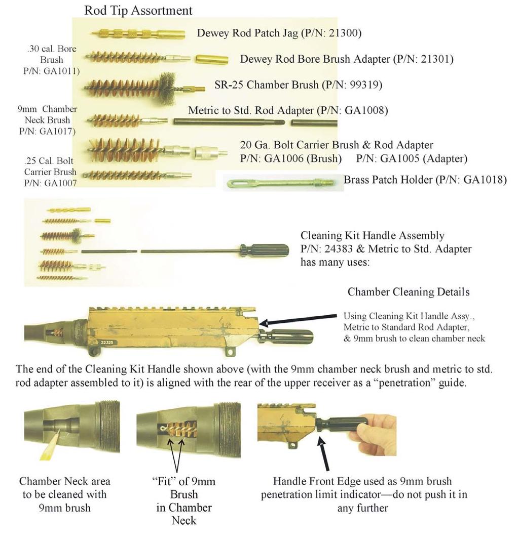
96 92


 Assemble the #8 Large Brass Bolt Carrier Brush and")
97 1-6: Using the Cleaning Kit components to clean the Bolt Carrier. Handle & Rod Adapter is used with the Chamber Brush, 9mm Chamber Neck Brush and Brass Patch Holder to clean the chamber. (1) Assemble the #9 Small Brass Bolt Carrier Brush to the #6 Chamber & Brass Brush Rod and insert it through the small diameter hole inside the bolt carrier. One or two passes with the brush will generally clean carbon from the bolt s tail piece recess. Rotate rod handle clockwise to keep the brush from unscrewing. Use #9 Small Brass Brush Use # 8 Large Brass Brush & #7 Adapter for Large Brass Brush (2) Assemble the #8 Large Brass Bolt Carrier Brush and its #7 Adapter to the #6 Chamber & Brass Brush Rod and insert it in the bolt carrier s bolt recess. Rotate rod handle clockwise 5 or 6 times to keep the brush from unscrewing and to clean carbon from the bolt recess. 93
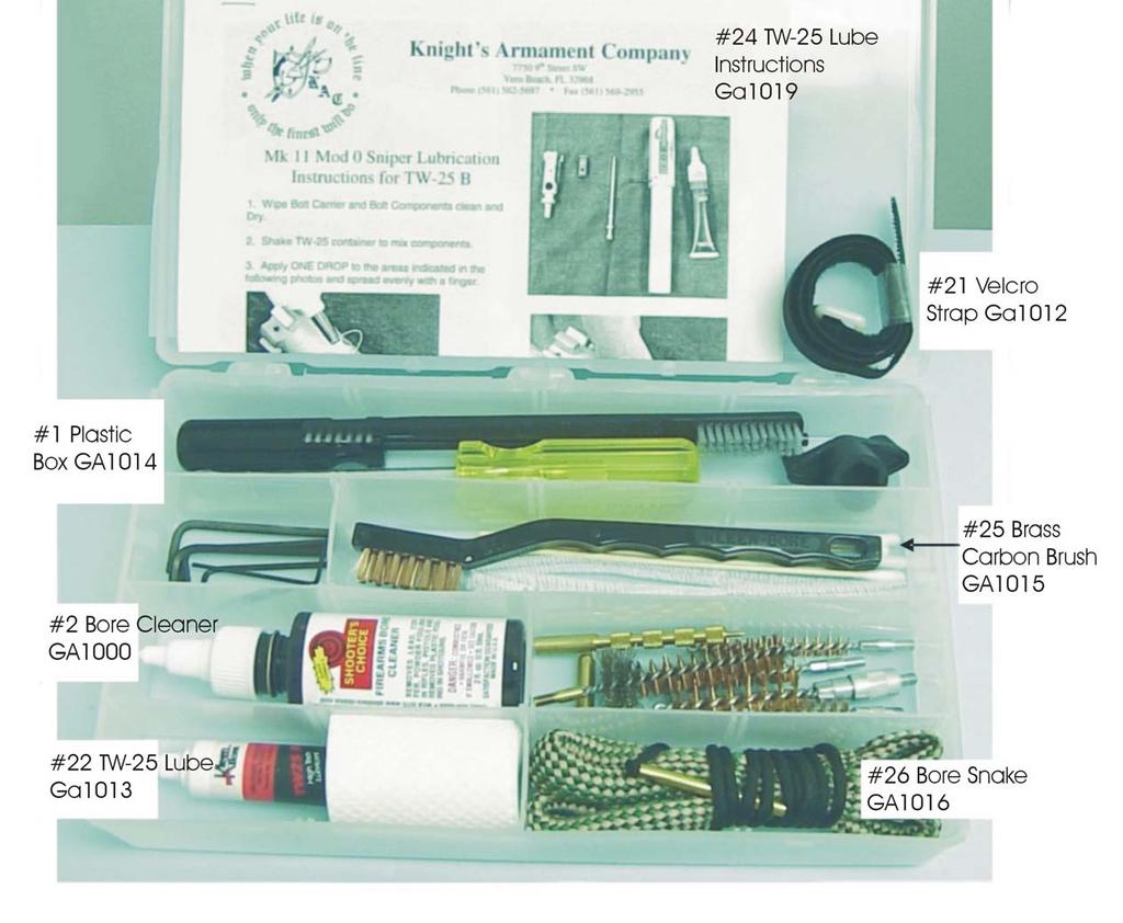
98 94
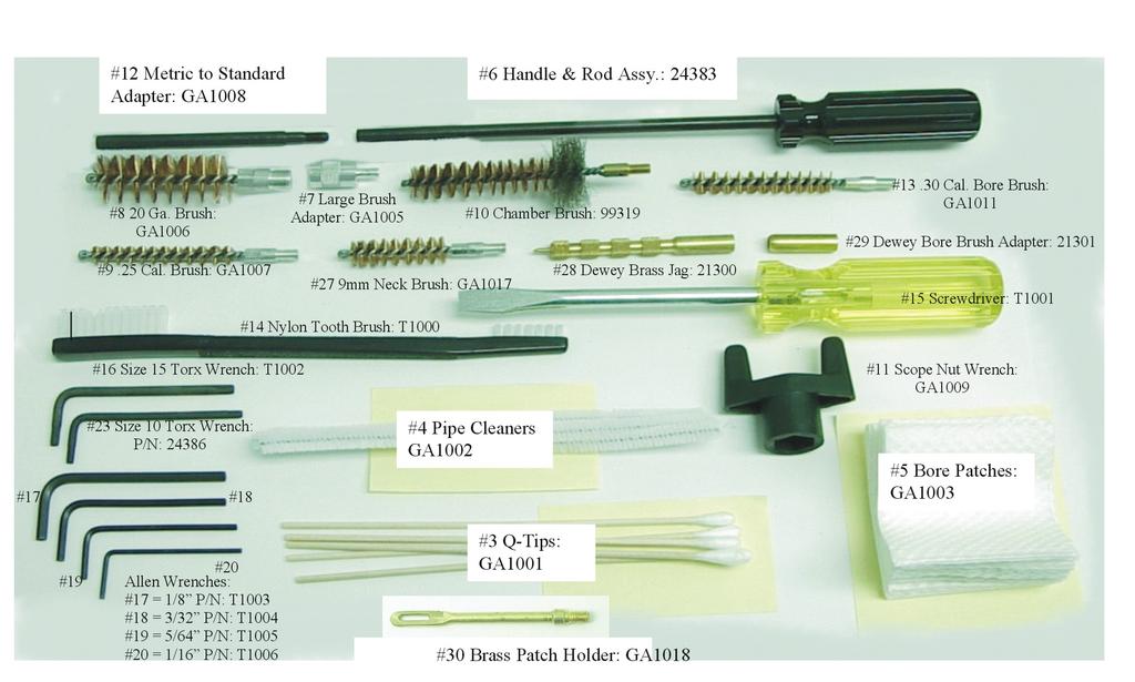
99 95


 (1) Generously coat with CLP and scrub thoroughly with GP brush.")


100 e. UPPER RECEIVER (1) Wipe inside of upper receiver with a clean rag wetted with CLP. Remove CLP with a clean dry rag. Repeat as necessary. (2) Use both ends of general purpose (GP) brush to clean around area where gas tube enters receiver and the charging handle track. A piece of string wet with CLP can be looped around the gas tube and pulled back and forth for cleaning where the brush will not reach. Caution: DO NOT BEND GAS TUBE with small end of brush. f. BOLT GROUP (note ejector cleaning procedure on next page) (1) Generously coat with CLP and scrub thoroughly with GP brush. Use small end of GP brush in cam pin hole and doubledover pipe cleaner in firing pin recess. See pipe cleaner and q-tip use illustrations below for firing pin hole, gas key, etc. (2) Scrub extractor, cam pin, and firing pin in similar manner. Be careful brush does not dislodge extractor spring. If necessary to re-seat extractor spring, place larger diameter end-coil into recessed hole in extractor body and press in on opposite end with the point of a round of ammunition. (3) Wipe parts with clean/dry rag. Repeat cleaning with CLP and GP brush if carbon is present or as necessary to remove fouling, then wipe clean and dry. Pipe Cleaner for Firing Pin Hole & Gas Key Q-Tips for Extractor & Cam Pin Recesses GP Brush on Bolt Lugs & Bolt Exterior 96


101 1. Apply 1 drop of CLP to the area around the ejector. 2. Hook case under extractor lip and depress ejector with thumb pressure several times. 3. Wipe away any excess or dirty CLP. Repeat steps 1 and 2 until the CLP works past the ejector and spring action is strong. Wipe away any excess CLP. FIGURE 3-1 Ejector Cleaning Procedures 97
102 g. CARRIER AND GAS KEY (1) Generously coat (inside and out) with CLP and scrub thoroughly with GP brush. Place two or three drops of CLP down the gas key. Use GP brush to clean the inside surfaces where the bolt rides. (2) A doubled-over pipe cleaner should be used to scrub the straight section of the gas key. A straight pipe cleaner wetted with CLP should be passed back and forth completely through the gas key into the inside area of the carrier. (3) Use small end of GP brush to scrub cam groove. Wipe all parts clean and dry with rags, patches, and pipe cleaners. (4) Clean small inside diameter of carrier with diagonal-half of a cleaning patch attached to bore rod tip. Pay particular attention to bolt recess in carrier and gas key. DO NOT USE Q-TIPS IN GAS KEY. h. LOWER RECEIVER GROUP (1) Use GP brush wrapped with pieces of rag, pipe cleaners, or bore rod with cleaning patches to wipe interior of lower receiver (trigger area) clean. CAUTION Do not use wire brushes or any abrasive material to clean aluminum surfaces. (2) Use a pipe cleaner to clean drain hole at end of buffer tube. (3) Clean interior of the buffer tube with a large piece of rag slightly wet with CLP attached to the end of the bore rod. Wipe buffer tube dry with a clean rag in the same manner. (4) If absolutely necessary, have an armorer remove hammer and trigger when detailed cleaning is required. 98
103 i. OTHER AREAS (1) Other metal surfaces are cleaned with CLP and a rag or the general purpose brush, and then wiped dry with a clean rag. (2) Plastic and rubber surfaces are cleaned with small amounts of water on a rag and then wiped dry. Do not let water enter the inside of the stock or lower receiver. j. When rifle parts are clean, lubricate for operational use as described in paragraph 3-2. k. If not yet assembled, follow reassembly procedures in paragraph 2-12 through SPECIAL OPERATOR MAINTENANCE PROCEDURES NOTE Special disassembly procedures are those not normally required each time the rifle is cleaned. These parts should only be disassembled and cleaned when their proper functioning is in question or suspected of causing malfunctions. They will usually require an Armorer s assistance or supervision. They are not included in this Operator s Manual as an authorization, they are described here solely to prevent damage from improper disassembly. For SR-M110, the Operator may remove the Lower URX Rail to gain access for barrel cleaning (under handguard). Refer to Section 2-21 on Page 41 of this Manual for URX Lower Rail Instructions. a. Mk 11 Mod 0 HANDGUARD REMOVAL--requires a strap wrench...see armorer. (1) With muzzle pointed away from you, hold handguard with weak hand and with strong hand--turn handguard nut to the left (counter-clockwise) with strap wrench. (2) Continue turning NUT with hand until handguard is free and lift handguard clear of barrel. Replace handguard as soon as possible to protect gas tube from being bent while handguard is removed. (3) Assembly is the reverse of the above except ensure that the handguard index pins enter the barrel nut's 3, 6, and 9 o'clock position as you begin turning the handguard nut. Use Armorer's strap wrench to tighten firmly (slightly more than hand tight). 99
104 b. MAGAZINE CATCH REMOVAL NOTE An Armorer will be required to remove the Bolt Catch before removing Magazine Catch. (1) Perform disassembly of magazine catch with upper receiver removed. Observe the action on the magazine catch lug through the magazine well by pushing the magazine release button several times. (2) With a section of cleaning rod, push the release button as far in as possible. (3) The left side of the catch (magazine catch lug) now clears the left side of the receiver. Unscrew the lug to the left (counter-clockwise) 3 turns and relieve pressure on release button. (4) Depress the button again, but only with finger pressure. Continue to unscrew the lug. WARNING The magazine release button is spring loaded. Once the lug is fully unscrewed, the button could fly out of the receiver and hit you in the eye or be lost. (5) Slowly release pressure on release button as lug finally comes loose from the button. As pressure is relaxed on button, capture it and the spring in your hand or in a rag held over the receiver. (6) Assembly is the reverse of the above. 100

 If the lug is screwed in too far, the lug will not clear the inside lip of the receiver. This condition will fail to release the magazine properly.")

105 c. MAGAZINE CATCH ADJUSTMENT (Mk 11 Mod 0 only, newer M110/Mk 11 Mod 2 Ambidextrous Models are not adjustable) (1) As the lug is screwed into the magazine catch button, more and more tension is applied to the catch assembly by the spring. Screw the lug into the button until the threaded end of the lug is just below flush with the surface of the button. (2) Observe the range of motion the button now has on the lug by viewing through the magazine well and pushing on the button. (3) If the lug is screwed in too far, the lug will not clear the inside lip of the receiver. This condition will fail to release the magazine properly. (4) If the lug is screwed out to far, spring tension on the button will be weak and the lug may even drop out of its recess when the button is pressed. Both of these conditions will fail to secure the magazine in the magazine well. New Model Ambidextrous Magazine Release d. Ambidextrous Bolt Latch (possible upgrade for future M110/Mk 11 type Rifles) is not User adjustable. New Model Ambidextrous Bolt Catch (Possible Future Upgrade) 101
106 3-7 CLEANING THE DAY OPTIC SIGHT a. Use lens cleaning kit supplied with rifle or scope. The M-110 has an Optics Cleaning Kit in its Deployment Kit. Use only silicone-free lens cleaning paper/tissue to wipe lenses. b. Remove dust, lint, dirt, and large particles by first blowing across the lenses. DO NOT BLOW ON LENSES IN COLD WEATHER. Then use a soft bristle clean/oil free camel's hair brush to gently sweep any debris from the lens. c. To remove finger prints, oil smudges, and other grime from the lens, apply lens cleaning fluid or isopropyl (rubbing) alcohol to a folded piece of lens cleaning paper. Wipe lens clean with a circular motion starting at the center of the lens and working outward. d. Clean outside metal surface of sight with a clean cloth. 3-8 CLEANING SCOPE MOUNTING RINGS a. If so attached, install and close dust covers over lenses before cleaning scope. b. Keep Allen screw heads clear of debris and rust. Use long bristles of general purpose (GP) brush to keep clean and clear. If rust is, or may be a problem, put a drop of CLP on each screw head, brush in and wipe off excess. c. Clean other areas of mounting rings, mounting nuts, etc., with GP brush. Apply a light coat of CLP to exterior metal parts. d. Remove and clean dust covers with a damp cloth. Wipe control knobs clean with a soft dry cloth. DO NOT OIL, USE SOLVENTS, OR CLP on control knobs or dust covers. 3-9 STORAGE (Temporary storage in unit armory, arms room, etc.) a. Ensure rifle is unloaded, clear and the hammer is down. Rifle should be cleaned and lubricated as described in paragraph 3-5 and 3-2 respectively. b. If possible store rifle vertically with muzzle pointed down. c. Never store ammunition or loaded magazines with the rifle!!! 102
107 SECTION IV: PREPARATION FOR SHIPMENT 3-10 PACKAGING FOR SHIPMENT WARNING Never ship the rifle with a round in the chamber, or ammunition in magazines, or system case. a. Remove any ammunition from rifle, magazines, and cases. Ensure rifle, components, and accessories are clean. Use metal banding around System Case. b. System case should be packed in a fiberboard (heavy duty/double walled cardboard) shipping box of appropriate size. Fill any voids in shipping box with cushioning material (see Appendixes A and D). c. Enclose a Packing List (DD Form 1750 or equivalent) and a description of work required or nature of malfunction. Include your (operator's or technician's) name and phone number so maintenance personnel can contact you directly if necessary. d. Close fiberboard box and seal all seams and joints with approved tape (see Appendixes A and D). Ship only one rifle per shipping box MARKING FOR SHIPMENT a. Mark in accordance with MIL-STD-129. b. Ship via U.S. Registered Mail, Return Receipts Requested. 103
108 CHAPTER 4 AMMUNITION 4-1 AUTHORIZED AMMUNITION WARNING Use only 7.62mm M118LR, M118 Special Purpose Ball, M852 Match, or other authorized ammunition, e.g., M80 Ball, M993 Armor Piercing. DO NOT FIRE corroded or dented cartridges, cartridges with loose bullets, cartridges with their bullets pushed in, cartridges longer than magazine or reloaded ammunition. 4-2 AMMUNITION WHICH FAILS TO FIRE Dispose of any misfired rounds in accordance with authorized procedures. 4-3 CARE, HANDLING, AND PRESERVATION a. Protect ammunition from mud, sand, and moisture. If ammunition gets dirty or wet, wipe it dry with a clean/dry cloth. If corrosion will not wipe clean of ammunition, properly dispose of it. b. Do not let ammunition be heated by the direct rays of the sun. If the ammunition is warm or hot to the touch, excessive pressure may damage the rifle or hurt you. Let ammunition cool/store in the shade before use. c. Do not oil or grease cartridges. Oiled cartridges produce dangerously high levels of bolt thrust against the locking lugs and may damage them. 104
109 APPENDIX A REFERENCES A-1 SCOPE This Appendix lists forms, field manuals, technical manuals, tables, regulations, standards, and miscellaneous publications referenced in this manual. A-2 TECHNICAL MANUALS TM Chemical, Biological and Radiological (CBR) Decontamination TM /1...Equipment Repair Procedures (USMC) TM Administrative Storage of Equipment TM Procedures for Destruction of Equipment to Prevent Enemy Use TM Ammunition General TM Care and Storage of Ammunition A-3 COMMON TABLE OF ALLOWANCES (CTA) CTA Army Medical Department Expendable/Durable Items CTA Expendable/Durable Items A-4 ARMY REGULATIONS AND PAMPHLETS DA PAM Consolidated Index of Army Publications and Blank Forms DA PAM The Army Maintenance Management System (TAMMS) A-5 FIELD MANUALS FM Nuclear, Biological and Chemical (NBC) Recon and Decontamination Operations FM First Aid for Soldiers FM NBC (Nuclear, Biological and Chemical) Defense FMFM 1-3B...Sniping (U.S. Marine Corps Publication) 105
110 A-6 TRAINING CIRCULAR TC Sniper Training and Employment A-7 FORMS DA Form Recommended Changes to Publications and Blank Forms DD Form Packing List SF Quality Deficiency Report A-8 MISCELLANEOUS MCO Handling, Transportation, Storage, Reclassification, and Disposal of Class V (W) Material (USMC) NAVMC 10558A...Weapon Record Book, Part II (USMC) MIL-STD Military Standard-Masking for Shipment and Storage PPP-B Federal Specifications - Boxes, Shipping, Fiberboard PPP-C Federal Specification - Cushioning Material PPP-C Federal Specification - Cushioning Material PPP-T-60...Federal Specification - Tape, Packaging, Waterproof A-A Federal Specification - Tape, Packaging, Waterproof TB Inspection and Certification of Gages - Small Arms. 106
111 APPENDIX B DESCRIPTION OF TOOL USAGE B-1 TOOLS a. T-Handle Torque Wrench (when combined with 1/2 Socket). (Optional Accessory used to torque day optic mounting nuts to 65 in. lbs.) b. Socket, Socket Wrench, 1/2". (Optional Accessory used with T-Handle Wrench to torque day optic mounting nuts) c. Key, Socket Head Screw 1/16". (Optional Accessory used for day optic sight elevation and windage dial set screws) d. Wrench, Combination, Box and Open, 1/2". See page 98. (Optional Accessory, use box end to remove day optic sight and initial or field tightening of mounting nuts) e. Key, T-15 Torx Head or T-10, or; Key, Socket Head Screw 5/64, 1/8, 3/32", and See Pages 99 and 100. (Optional Accessories used for day optic sight ring cap screws, front sight post adjusting, etc., all wrenches included in Mk 11 Navy Cleaning Kit) 107
112 CLAMP 90 Degrees Past Finger Tight TO REMOUNT KMC SCOPE RINGS WHEN THE 65-INCH POUND T-HANDLE TORQUE WRENCH IS NOT AVAILABLE, USE THE 1/2-INCH COMBINATION WRENCH IN THE CLEANING KIT AS FOLLOWS: 1. MOUNT RINGS AND SCOPE ASSY. ON THE RAIL IN THE DESIRED POSITION, AND LOOSELY TIGHTEN THE HEX NUTS WITH YOUR FINGERS. 2. WITH THE NUTS SLIGHTLY LOOSE, POSITION CLAMPS AND PUSH THE SCOPE AS FAR FORWARD AS THE RECOIL GROOVES ALLOW. 3. WHILE HOLDING THE SCOPE FORWARD, FINGER TIGHTEN THE FRONT HEX NUT AS MUCH AS POSSIBLE. REPEAT FOR THE REAR HEX NUT. 4. WITH THE 1/2-INCH COMBO WRENCH IN THE CLEANING KIT, TIGHTEN THE FRONT HEX NUT AN ADDITIONAL 90 DEGREES. REPEAT FOR THE REAR HEX NUT. 5. THIS FIELD MOUNTING PROCEDURE WILL BE CLOSE TO THE DESIRED TORQUE VALUE, AND REPEAT A GOOD ZERO IF PERFORMED EXACTLY THE SAME EACH TIME. Use for: Scope Mount Nuts Figure B-1 Use of ½ Combination Wrench with Scope Ring Nuts (Same for SR-M110 1-Piece Mount) 108
113 3/32 Hex Screw or T-15 Torx Screw The SR-25 Cleaning Kit contains 3/32 Hex Head and T-15 Torx Head Screw wrenches. On a weekly basis, check the tightness of the scope ring cap screws with the correct wrench. T-10 Torx Size Screws also used. However, do not use the wrench s long arm to check the screw tightness. Use the short arm to feel if the screw is lose. If you use the wrenches long arm, you will move the screw and change the torque setting from the factory. **** CAUTION **** Using the wrench s long arm may overtighten and break the screws. Figure B-2 Use of Hex or Torx Wrench with Mk 11 Mod 0 Scope Ring Caps 109
114 Position Scope In Bases Install Scope Ring Bases to Receiver Push bases forward as you finger tighten 1/2-inch hex base nut MM MM 1. Install Scope Ring Bases to Receiver Rail finger tight. The forward ring should be positioned in the second groove from the front, and the rear ring positioned in the thirteenth groove. Ensure gaps are even on both sides. Install Ring Caps to Bases 2. Remove Ring Caps and clean away any oil or dirt from the scope and ring mating surfaces. Position scope in bases as shown. 3. The scope and ring positions shown above should allow for the appropriate eye relief. However, subsequent re-positioning may be required to accommodate different shooters or firing positions MM 4. Install the ring caps to the bases with the screws provided with the rings. While only finger tightening the cap screws, ensure that the gap between each cap and its base is equal on both sides of the ring. 3/32 Hex or T-15 Torx T-10 Torx Size also used. 1 3 Torque Cap Screws to 13-Inch/Lbs in the numbered tightening Sequence shown. 5. Torque the cap screws to 13-Inch/Pounds with a properly calibrated torque driver while following the numbered pattern shown to the right. Ensure the gaps are equal after tightening. 6. Torque 1/2-inch hex base nuts to 65-Inch/Pounds with a properly calibrated torque wrench. 4 2 Figure B-3 Use of Tools for Mk 11 Mod 0 Scope Mounting (Use same basics for M-110 Scope Base) 110
115 APPENDIX C SYSTEM ITEMS THAT MAY APPLY TO YOUR RIFLE C-1 GENERAL The operator is authorized to order the following optional Government Supply System accessories: Note: P/N s listed are US Government, not KAC NO. FSCM/CAGE PART NO. NOMENCLATURE NSN: Sling, Small Arms, Leather Brush, Cleaning, GP Brush, Bore (.30"/7.62mm) Oil Bottle AW2 1/16" Key, Socket Head Screw BA /32" Key, Socket Head Screw G Wrench, Box and Open 1/2" Swabs, Cleaning Small Arms A T-Handle Section A Cleaning Rod Section, 4 ea Swab Holder A Adapter, Bore Brush to Rod Section (converts 8-36 to 8-32) Case, Accessory, SA (Rod sections & T-Handle) GG-A-616 Applicator, (Q-Tips) NNN-P-40 Paper, Lens (Cleaning Tissue) L-B-56A Bottle (for containing Isopropyl Alcohol) H-B-118 Brush, Artists (Cleaning Brush) A Case, Lens Cleaning A-A-1404 Socket, Socket Wrench 1/2" A T-Handle Torque Wrench A Day Optic Sight Ring Screws
116 APPENDIX D EXPENDABLE/DURABLE SUPPLIES AND MATERIALS LIST D-1 SCOPE This appendix lists expendable and durable supplies and materials that the operator will need to operate and maintain the SR-25 Sniper Rifle System. This listing is for informational purposes so all personnel will be aware of the items available to support the user. It is not authorization to requisition the listed items. These items are authorized to you by CTA , Expendable/Durable Items (except Medical, Class V, Repair Parts, and Heraldic Items), or CTA 8-100, Army Medical Department Expendable/Durable Items. D-2 EXPLANATION a. LEVEL. This column identifies the lowest level of maintenance that requires the listed items: C - Operator/Crew F - Intermediate Direct Support Maintenance b. U/M (Unit of Measure). Indicates the measure used in performing the actual maintenance function. This measure is expressed by a two-character alphabetical abbreviation (e.g., ea., in., pr.). If the U/M differs from the unit of issue, requisition the lowest unit of issue that satisfies your requirements. EXPENDABLE / DURABLE SUPPLIES AND MATERIALS LIST ITEM NO. LEVEL NSN DESCRIPTION U/M 1 C ALCOHOL, ISOPROPYL, (Cleaning Fluid) (81348) TT1735, 1 qt. can QT 2 C APPLICATOR (Q-TIPS) (81348) GG-A per pk EA 112
117 EXPENDABLE / DURABLE SUPPLIES AND MATERIALS LIST ITEM NO. LEVEL NSN DESCRIPTION U/M 3 C BOTTLE (FOR CONTAINING ISOPROPYL ALCOHOL), (81348) L-B-56A, 1 oz. bottle EA 4 F BOX, SHIPPING (81348) PPP-B-636, 12 in. x 12 in. x 48 in. 10 each BL 5 C BRUSH, ARTIST (Lens Cleaning), (81348) H-B-118 EA 6 C BRUSH, BORE (.30"/7.62mm), (19204) EA 7 C TBD BRUSH, CHAMBER (SR-25) EA 8 C BRUSH, CLEANING, SMALL ARMS (19204) (Double End Tooth Brush) EA 10 C CLEANER, LUBRICANT, PRESERVATIVE (CLP) (81349) MIL-L-63460, 1/2 oz. bottle OZ OZ 11 F CUSHIONING MATERIAL (81348) PPP-C-1842, 325 in. x 12 in. x 1/4 in. RO 12 F CUSHIONING MATERIAL (81348) PPP-C-843, 100 ft. x 6 in. x 3/4 in. RO 113
118 EXPENDABLE / DURABLE SUPPLIES AND MATERIALS LIST ITEM NO. LEVEL NSN DESCRIPTION U/M 13 C LUBRICATING OIL, ARCTIC WEAPONS (LAW) (81349), MIL-L-14107, 1 qt. can QT 14 C LUBRICATING OIL, WEAPONS (LSA), SEMI-FLUID (81349) MIL-L oz. plastic bottle 4 oz. plastic bottle OZ OZ C C C F PAPER, LENS (81348) NNN-P-40 (Cleaning Tissues), 50 sheet pk. RAG, WIPING, (58536) A-A-531, 50 lb. bl. SWAB, SMALL ARMS CLEANING (2.5" X 2.5") (19204) , 200 per bl. (.30"/7.62mm) TAPE, PRESSURE SENSITIVE, PAPERBACK, WATER-RESISTANT (58536) A-A-1683, 2 in. wide, 120 yd. roll EA LB EA YD 19 F TAPE, PRESSURE SENSITIVE, CLOTHBACK, WATER-RESISTANT (81348) PPP-T-60, 2 in. wide, 60 yd. roll YD 114
119 APPENDIX E CORROSION PREVENTION AND CONTROL (CPC) The supplies and materials required for Corrosion Prevention Control (CPC) are listed within Appendix D, Expendable/Durable Supplies and Materials List. Preventive Maintenance Checks and Services are in Chapter 2, Section IV (see Paragraph 2-20). Rifle CPC is addressed in Chapter 2, Section VI: Operation Under Adverse Conditions (see Paragraphs 2-25 through 2-28), and the Lubrication Guide in Paragraph 3-2 as well as Paragraph 3-3: General. Ammunition CPC is addressed in Chapter 4. CPC of ordinance equipment and other material is a matter of continuing concern for all personnel. It is important that any corrosion problems with your Sniper Rifle System be reported so that the problem can be corrected and improvements can be made to prevent the problem in the future. Although corrosion or "rust" is commonly associated with the surface deterioration of metals, it can also include the deterioration of other materials such as rubber and plastic items. However, for the purposes of CPC, corrosion also includes unusual cracking, softening, swelling, or breaking of items made from these materials. If corrosion or premature failure of components is identified, it should be reported using Standard Form 368, Quality Deficiency Report. Use "key words" such as "corrosion", "rust", "deterioration", or "cracking" to ensure your problem information is identified as a CPC problem. The form should be submitted to: KNIGHT'S MANUFACTURING COMPANY 701 Columbia Blvd. Titusville, Florida militaryops@knightarmco.com Note: U.S. Navy personnel will use the following point of contact: Naval Surface Warfare Center (Code 4081), 300 Highway 361, Crane IN (attn: Mr. Terry O Brian, Commercial Telephone (812) or Fax (812)

120 116
SASS M110 Repair Parts
 HOURLY REPAIR RATE $ CONTRACTOR REPAIR/REPLACEMENT 25362 2-Stage Match Trigger, 4.5 lbs. N/A 25362 94354 Trigger N/A 25362 94031 Spring, Sear N/A 25362 25361 Match Front Hook, (Sear) (6-40 Threaded) N/A
Cleaning rod: spring steel, stainless steel or carbon fibre cleaning rod - only use a one-piece rod. Avoid using snakes.
 Telemark Biathlon Where performance and precision come together http://telemarkbiathlon.com Rifle Cleaning Date : July 19, 2013 Anschutz Rifle Manual - Click Here Izhmash 7-3 Rifle Manual - still looking
STRIBOG GRAND POWER. The INSTRUCTIONS FOR USE, MAINTENANCE AND SAFETY. 1
 instructions The for use, maintenance STRIBOG and safety hestribog GRAND POWER INSTRUCTIONS FOR USE, MAINTENANCE AND SAFETY www.grandpower.eu 1 The STRIBOG Dear Customer, Thank you for purchasing a semi-automatic
2-1. CLEARING PROCEDURES
 CHAPTER 2 MAINTENANCE Proper maintenance contributes to weapon effectiveness as well as unit readiness. This chapter discusses the maintenance aspects of the M249 AR to include inspection; cleaning and
REC7 DI OPERATOR S MANUAL
 EC7 D REC7 DI OPERATOR S MANUAL TABLE OF CONTENTS 2 2 4 5 6 6 6 8 8 10 11 12 12 13 13 15 18 20 22 USE OF THIS MANUAL SAFETY GUIDELINES WARRANTY AND SERVICE NOTES FUNCTIONS AND FEATURES BREAK IN PROCEDURE
TM WARNING SUMMARY
 TM 9-005-239-0 WARNING SUMMARY Treat every firearm as if it were loaded. Never accept or take over a firearm from another until you have checked personally to see that it is unloaded or in a completely
-
 Operator s manual SM-95202 Brügger & Thomet AG P.O. Box 42 3608 Thun Switzerland Fon +41 33 334 67 00 Fax +41 33 334 67 01 info@brugger-thomet.ch www.brugger-thomet.ch TABLE OF CONTENTS SAFETY instructions
CHAPTER 2 MAINTENANCE
 CHAPTER 2 MAINTENANCE This chapter addresses the proper care of the machine gun to ensure its overall effectiveness and efficient functioning. The information includes the gunner's knowledge in disassembly
M16 R / M1600 R USER S MANUAL WARNING: READ THE INSTRUCTIONS AND SAFETY PRECAUTIONS IN THIS MANUAL CAREFULLY BEFORE USING THIS FIREARM.
 ARMSCOR M16 R / M1600 R USER S MANUAL WARNING: READ THE INSTRUCTIONS AND SAFETY PRECAUTIONS IN THIS MANUAL CAREFULLY BEFORE USING THIS FIREARM. DISCHARGING FIREARMS IN POOLY VENTILATED AREAS, CLEANING
Be sure the cam pin is installed in the bolt group. If it isn t, your rifle can still fire and will explode causing injury.
 Responsibility This manual provides instructions on the operation and maintenance of the Barrett model M468 rifle. Read and understand it carefully before you try to use your rifle. Your safety, and that
INTRODUCTION TO THE SERVICE RIFLE AND MAINTENANCE
 INTRODUCTION TO THE SERVICE RIFLE AND MAINTENANCE 1 OVERVIEW DISASSEMBLY MAINTENANCE ASSEMBLY 2 TERMINAL LEARNING OBJECTIVE Given a service rifle, Common Combat Sling, and cleaning gear maintain a service
INSTRUCTION MANUAL CZ 630/631
 INSTRUCTION MANUAL CZ 630/631 Before handling the air rifle read this manual carefully and observe the following safety instructions. Improper and careless handling of the air rifle could result in unintentional
OPERATION AND FUNCTION
 CHAPTER 3 OPERATION AND FUNCTION This chapter discusses the operation of the M249 automatic rifle. This includes loading, unloading, cycle of functioning, adjusting the sight, and using the bipod. 3-1.
AR STYLE FIREARMS OWNER'S MANUAL: OPERATION, HANDLING, DISASSEMBLY / REASSEMBLY & SAFETY INSTRUCTIONS
 AR STYLE FIREARMS OWNER'S MANUAL: OPERATION, HANDLING, DISASSEMBLY / REASSEMBLY & SAFETY INSTRUCTIONS - DO NOT DISCARD THIS MANUAL - READ THIS MANUAL CAREFULLY, PAYING CLOSE ATTENTION TO THE INSTRUCTIONS
AR /.223, 300 BLK, 22 Nosler,.224 Valkyrie. Covers. and. rifle models INSTRUCTION MANUAL
 AR-15 5.56/.223, 300 BLK, 22 Nosler,.224 Valkyrie Covers TM, TM and, TM rifle models INSTRUCTION MANUAL WARNING: BEFORE USING THIS FIREARM, READ AND FOLLOW THESE INSTRUCTIONS Safety First Thank you for
ARAK-21 OPERATOR SAFETY AND INSTRUCTION MANUAL
 ARAK-21 OPERATOR SAFETY AND INSTRUCTION MANUAL NOTICE: The ARAK-21 Upper Assembly itself is not considered a Firearm under federal law or the National Firearms Act. The ARAK-21 Upper Assembly mounted on
ODEL 95 OPERATOR S MANUAL
 ODEL 95 MODEL 95 OPERATOR S MANUAL TABLE OF CONTENTS 2 2 3 5 6 6 6 7 7 8 8 11 11 12 12 19 20 22 24 26 MANUFACTURER S DISCLAIMER USE OF THE MANUAL SAFETY GUIDELINES WARRANTY AND SERVICE DESCRIPTION OF FIREARM
Figure 2-1. SAFE ( S ) position.
 position.") CHAPTER 2 OPERATION AND FUNCTION This chapter includes clearing, disassembly and assembly, loading, operating precautions, and cycle of operation. 2-1. CLEARING Clear the MK 19 differently in a firing
CHAPTER 2 OPERATION AND FUNCTION This chapter includes clearing, disassembly and assembly, loading, operating precautions, and cycle of operation. 2-1. CLEARING Clear the MK 19 differently in a firing
Colt Advanced Law Enforcement Carbines
 OPERATOR S MANUAL FOR: Colt Advanced Law Enforcement Carbines LE6940 LE6944 LE6943 LE6945CQB & LE6946CQB COPYRIGHT 2010 COLT DEFENSE LLC ALL RIGHTS RESERVED Information contained in this publication is
INSTRUCTION MANUAL. Slavia 630/631
 INSTRUCTION MANUAL Slavia 630/631 Before handling the air rifle read this manual carefully and observe the following safety instructions. Improper and careless handling of the air rifle could result in
OWNER S MANUAL FOR OA SERIES FIREARMS
 OWNER S MANUAL FOR OA SERIES FIREARMS 620-626 Old Pacific Hwy SE Olympia, WA 98513 (360) 459-7940 WARNING To avoid accidental firing, BE SURE WEAPON IS CLEAR. Failure to do so could result in serious injury
SAFETY RULES WARNING: READ THESE SAFETY RULES & OPERATORS MANUAL BEFORE HANDLING YOUR FIREARM
 SAFETY RULES WARNING: READ THESE SAFETY RULES & OPERATORS MANUAL BEFORE HANDLING YOUR FIREARM Never point a firearm at anyone and always keep the muzzle pointed in a safe direction. Always treat all firearms
P9S Automatic Pistol Caliber.45 ACP
 P9S AUTOMATIC PISTOL Caliber.45 ACP P9S Automatic Pistol Caliber.45 ACP Instruction Manual HECKLER & KOCH, INC. 2148 Pacific Boulevard Sterling, Virginia 20166-8903 U.S.A. TEL. (703) 450-1900 TELEFAX (703)
MODEL 1400 E USER S MANUAL WARNING: READ THE INSTRUCTIONS AND SAFETY PRECAUTIONS IN THIS MANUAL CAREFULLY BEFORE USING THIS FIREARM.
 ARMSCOR MODEL 1400 E USER S MANUAL WARNING: READ THE INSTRUCTIONS AND SAFETY PRECAUTIONS IN THIS MANUAL CAREFULLY BEFORE USING THIS FIREARM. DISCHARGING FIREARMS IN POORLY VENTILATED AREAS, CLEANING FIREARMS
SAR-15 RIFLE OWNERS MANUAL
 SAR-15 RIFLE OWNERS MANUAL SIONICS WEAPON SYSTEMS Our mission is to manufacture quality firearms made with pride in the USA. We are able to do accomplish this by using only the best American made parts.
PISTOL CALIBER AR STYLE FIREARMS
 PISTOL CALIBER AR STYLE FIREARMS OWNER'S MANUAL: OPERATION, HANDLING, DISASSEMBLY / REASSEMBLY & SAFETY INSTRUCTIONS - DO NOT DISCARD THIS MANUAL - READ THIS MANUAL CAREFULLY, PAYING CLOSE ATTENTION TO
Armed Officer's Training Manual Nomenclature and Inspection
 Armed Officer's Training Manual Section 8: Nomenclature and Inspection Learning Goal: The student will know the components and understand the operation of the service revolver and semi-automatic pistol.
INSTRUCTION MANUAL FOR
 PM333 INSTRUCTION MANUAL FOR SILENT-SR ISB FOR THE RUGER 10/22 TAKEDOWN and THE 22 CHARGER PISTOL TAKEDOWN MODEL READ THE INSTRUCTIONS AND WARNINGS IN THIS MANUAL CAREFULLY BEFORE USING THIS SUPPRESSOR
Please visit our website at and leave your comments.
 We promise our customers the best services and premium quality products with value. MODIFY and its logo are registered trademarks. Please visit our website at www.modify.com.tw and leave your comments.
INSTRUCTION MANUAL CZ 92
 INSTRUCTION MANUAL CZ 92 Before handling the pistol read this manual carefully and observe the following safety instructions. Improper and careless handling of the pistol could result in unintentional
OWNER S MANUAL. Read the instructions and warnings in this manual carefully before using this firearm; do not discard this manual.
 OWNER S MANUAL SDP compact Read the instructions and warnings in this manual carefully before using this firearm; do not discard this manual. This instruction manual should always accompany this firearm
XM8 US M4 System Comparison
 XM8 US M4 System Comparison HECKLER & KOCH DEFENSE Inc. System Weight: Overall Length: XM8 Lightweight Modular Weapon System (includes integrated sight with IR laser & illuminator, red dot reflex sight,
Owner s Manual Addendum (36310, 36311)
") FN15 DMR Owner s Manual Addendum (36310, 36311) We are pleased that you have chosen an FNH USA FN 15 Designated Marksman Rifle (DMR). The FN 15 DMR shares the same reliability, durability, quality and
FN15 DMR Owner s Manual Addendum (36310, 36311) We are pleased that you have chosen an FNH USA FN 15 Designated Marksman Rifle (DMR). The FN 15 DMR shares the same reliability, durability, quality and
OWNER S MANUAL READ THIS MANUAL BEFORE USING YOUR NEW AIRGUN
 OWNER S MANUAL READ THIS MANUAL BEFORE USING YOUR NEW AIRGUN FX SUPER SWIFT Table of Contents Warranty Specifications General Instructions Operating Instructions Trigger Adjustments Care & Maintenance
VR1 Owner s Manual. Vigilance Rifles, Inc Plum Lane Redlands, CA P F
 VR1 Owner s Manual Vigilance Rifles, Inc. 1653 Plum Lane Redlands, CA 92374 P 909.307.8877 F 909.307.8866 www.vigilancerifles.com INTRODUCTION: Vigilance Rifles offers a new line of Semi-Automatic Rifles
OPERATION AND FUNCTIONING
 C1, FM 23-65 * CHAPTER 3 OPERATION AND FUNCTIONING This chapter explains the operation of the MG. It discusses the loading, unloading, and clearing procedures, and the cycle of functioning of the weapon.
INNOVATIVE REFINEMENTS TO THE TACTICAL CARBINE
 INNOVATIVE REFINEMENTS TO THE TACTICAL CARBINE www.usamade-ar15parts.com USER MANUAL AR15 STYLE RIFLES Barnes Precision Machine A2-Style muzzle device. Reduces muzzle blast and felt recoil, complete with
COLT AUTOMATIC PISTOL
 COLT AUTOMATIC PISTOL CALIBER.22 INSTRUCTIONS FOR ASSEMBLY - DISASSEMBLY CLEANING COLT AIUTOMATIC PISTOL IN 6 INCH OR 4}~2 INCH BARREL.22 Long Rifle, rim fire Cartridge Capacity of Magazine, 10 Shots Description
OPERATOR S MANUAL FOR AR-24 SERIES PISTOLS
 OPERATOR S MANUAL FOR AR-24 SERIES PISTOLS ArmaLite Incorporated Box 299 Geneseo Illinois U.S.A. 61254 309-944-6939 ArmaLite.com 2006 ArmaLite Inc. This book provides instructions on the operation and
SIG SAUER ENHANCED AUTO MIL SPEC TRIGGER KIT INSTALLATION INSTRUCTIONS
 SIG SAUER ENHANCED AUTO MIL SPEC TRIGGER KIT INSTALLATION INSTRUCTIONS 1.0 Warnings 2 www.sigsauer.com This SIG SAUER Enhanced Mil-Spec Auto Trigger Kit comes complete with all parts and detailed installation
Titan FAR.308 Rifle and Carbine
 $4.95 John C. Garand Patron Saint of Fulton Armory FULTON ARMORY Over 20 years of excellence! Titan FAR.308 Rifle and Carbine User s Guide to Operation and Maintenance Fulton Armory 8725 Bollman Place
CONTENTS INTRODUCTION. WARNING: This manual contains important warnings that must be understood before using this firearm.
 CONTENTS Safety Rules...............................Page 2 Operation................................Page 5 Major Components.........................Page 6 Assembly.................................Page
SHF R50 SHF S50 Safety Harbor Firearms, Inc. PO Box 563 Safety Harbor, FL Ph: Fax:
 SHF R50 SHF S50 Safety Harbor Firearms, Inc. PO Box 563 Safety Harbor, FL 34695-0563 Ph: 727-726-2500 Fax: 727-797-6134 www.safetyharborfirearms.com 1 ^ WARNING Risk of serious injury or death. Failure
M mm Semiautomatic Rifle
 M4-5.56 mm Semiautomatic Rifle What is the FM concerning the M4 Rifle? FM 3-22.9 What is the first thing you should do when you handle a weapon? Make sure you clear it Name the five phases in Basic Rifle
Chapter 11 Small Arms Weapons
 Review Questions Chapter 11 Small Arms Weapons 1. On an M16 rifle, where is the magazine release button located? 1. Right side of the weapon, top front of the trigger guard 2. Right side of the weapon,
Beeman Precision Airguns Spring-Piston Air Rifles P1, P3, P11
 Beeman Precision Airguns Spring-Piston Air Rifles P1, P3, P11 User Instruction Manual V1 10/17 CONTENTS Rules of safe shooting...3 Cocking & Loading... 4 Safety... 4 Sight Adjustment...5 Trigger Adjustment...5
AR15/ BCA 10 RIFLE OWNER S MANUAL
 AR15/ BCA 10 RIFLE OWNER S MANUAL THIS IS NOT A SAFETY MANUAL. IF YOU NEED ASSISTANCE WITH THE SAFE HANDLING OF THIS, OR ANY FIREARM, PLEASE CONTACT A CERTIFIED FIREARMS INSTRUCTOR OR SCHOOL. Fundamental
INSTRUCTION MANUAL CZ 750
 INSTRUCTION MANUAL CZ 750 Before handling the firearm read this manual carefully and observe the following safety instructions. Improper and careless handling of the firearm could result in unintentional
Operation Manual Spring Operated Break-Barrel & Under-Lever Pellet Rifles
 WARNING: This gun can cause serious injury or death. Read and follow the instructions carefully. Do not load a pellet into the gun until you are ready to shoot. If you do load a pellet and then decide
INSTRUCTION MANUAL FOR. Models featured include: LF556, LF300, LF308, and LF6.5.
 INSTRUCTION MANUAL FOR Models featured include: LF556, LF300, LF308, and LF6.5. READ THIS MANUAL THOROUGHLY, PARTICULARLY THE WARNINGS, BEFORE USING THIS FIREARM Copyright 2016 Live Free Armory. All rights
SEMIAUTOMATIC SHOTGUN OWNER'S MANUAL
 SEMIAUTOMATIC SHOTGUN OWNER'S MANUAL ARMSAN@ARMSAN.COM TECHNICAL DATA Caliber :12 gauge / 20 gauge / 28 gauge Operation: Semi-Automatic, Gas Operated System Barrel Length: 20 (51cm), 24 (61cm), 26 (66cm),
OPERATOR S INSTRUCTIONS for the ARMALITE AR-30 RIFLE
 P.O. Box 299 Geneseo IL 61254 Tel 309-944-6939 fax 309-944-6949 armalite@geneseo.net OPERATOR S INSTRUCTIONS for the ARMALITE AR-30 RIFLE August 10, 2002 I. INTRODUCTION Description: Figure 1, The AR-30
INSTRUCTION MANUAL CZ 75 TS
 INSTRUCTION MANUAL CZ 75 TS CZ 75 TS - INSTRUCTION MANUAL Before handling the pistol read this manual carefully and observe the following safety instructions. Improper and careless handling of the pistol
MECH-TECH SYSTEMS CCU MODEL FOR GLOCK PISTOLS
 MECH-TECH SYSTEMS CCU MODEL FOR GLOCK PISTOLS Operation & Maintenance Manual Read and understand this manual before attempting to use this product. If you have any questions call: 1-866-433-2122 www.mechtechsys.com
ENR Enterprises, LLC. ENR 15 Manual
 ENR Enterprises, LLC ENR 15 Manual Table of Contents Disclaimer of Liability 2 Warnings: Dangerous Procedures 3 General Safety Warnings 4 Main Features and Overview 6 Rifle Clearing Before Use 7 Safety
TABLE OF CONTENTS READ FIRST
 TABLE OF CONTENTS READ FIRST PAGE INTRODUCTION............................. 1 NOTICES.................................. 1 WARNINGS................................ 2 PRECAUTIONS WHEN USING THIS FIREARM......
Smallbore rifle CZ99 PRECISION..22 Long Rifle.22 Win. Mag. R.F..17 Hornnady Mag. R.F.
 Smallbore rifle CZ99 PRECISION.22 Long Rifle.22 Win. Mag. R.F..17 Hornnady Mag. R.F. Fig. 1 22. Long Rifle, Model CZ 99 PRECISION 22 Long Rifle 22 Long Rifle for Sound Moderator 22 Win. Mag. R. F. 17
Before handling the firearm read this manual carefully and observe the following safety instructions. CONTENTS
 Before handling the firearm read this manual carefully and observe the following safety instructions. Improper and careless handling of the firearm could result in accidental discharge and cause injury,
Barrel Assembly. Field Stripping
 WARNINGS: Carry out safety check before handling the weapon. The weapon is heavily oiled for shipping. Clean and lubricate before firing. These procedures given apply only to the US Ordnance QCB version.
INSTRUCTION MANUAL CZ 75 Champion
 INSTRUCTION MANUAL CZ 75 Champion CZ 75 CHAMPION - INSTRUCTION MANUAL Before handling the pistol read this manual carefully and observe the following safety instructions. Improper and careless handling
CLEANING HANDGUNS TOOLS YOU WILL NEED
 CLEANING HANDGUNS CLEANING HANDGUNS If you take pride in your firearm, then you know how important it is to properly maintain your weapon. With good, consistent care, you not only make your gun look good
22-17 Partner. Owner s Manual. 624 Old Pacific Hwy SE Olympia, WA Tel (800) Fax (360) Available Rifle Kit
 Fax (360) Available Rifle Kit") Available Rifle Kit Complete Upper Receiver Kit 624 Old Pacific Hwy SE Olympia, WA 98513 Tel (800) 228-3471 Fax (360) 491-3447 Owner s Manual 22-17 Partner Warnings & Operation Do not attempt to fire the
Available Rifle Kit Complete Upper Receiver Kit 624 Old Pacific Hwy SE Olympia, WA 98513 Tel (800) 228-3471 Fax (360) 491-3447 Owner s Manual 22-17 Partner Warnings & Operation Do not attempt to fire the
Kentucky Long Rifle.50 BMG Model: BA M-N-M Tactical. Users Guide
 Kentucky Long Rifle.50 BMG Model: BA M-N-M Tactical Users Guide Metals-N-More Bowling Green, KY 42101 Telephone 270-781-3642 Fax 270-781-3766 Email Info@Kentucky50.Com www.kentucky50.com INTRODUCTION Congratulations
MARINE CORPS INSTITUTE INSPECTION AND REPAIR OF THE M9 PISTOL
 MARINE CORPS INSTITUTE INSPECTION AND REPAIR OF THE M9 PISTOL MARINE BARRACKS WASHINGTON, DC Table of Contents Page Contents... Navigation Instructions... i iii Chapter 1 Disassembly and Assembly of the
MRAD. Operator s Manual. (Multi-Role Adaptive Design) PO Box 1077 Murfreesboro, TN USA / / FAX /
 PO Box 1077 Murfreesboro, TN USA / / FAX /") MRAD (Multi-Role Adaptive Design) Operator s Manual PO Box 1077 Murfreesboro, TN 37133 USA / 615.8962938 / 615.896.7313 FAX / mail@barrett.net 03-23-11 P# 12925 Use of this manual Before you handle the
MRAD (Multi-Role Adaptive Design) Operator s Manual PO Box 1077 Murfreesboro, TN 37133 USA / 615.8962938 / 615.896.7313 FAX / mail@barrett.net 03-23-11 P# 12925 Use of this manual Before you handle the
Thank you for buying Bushmaster
 AZ 16010 Before disassembling, loading, or using this firearm, please Read, Understand, and Follow all the instructions in this manual, regarding proper handling and safe use!! Caution: If unfamiliar with
HONEY BADGER BY Q - PERSONAL OFFENSIVE WEAPON
 FIREARM SAFETY RULES STATE FIREARM LAWS MORE LAWYER SHIT SPECS HONEY BADGER BY Q - PERSONAL OFFENSIVE WEAPON CALIBER BARREL LENGTH TWIST RATE MUZZLE THREAD MUZZLE DEVICE LENGTH (COLLAPSED) LENGTH (EXTENDED)
Military Assault Rifle Operator Manual
 Military Assault Rifle Operator Manual 22 WARNINGS - Never Point any weapon, loaded or unloaded, at anything you do not intend to shoot. - Load and Unload with the muzzle pointed in a safe direction. -
FRONT BOLT ACTION ASSAULT SHOTGUN
 SPECIFICATIONS: CATEGORY........... IMPROVISED; NOTE: CAN BE MANUFACTURED COMMERCIALLY CALIBRE............ 410 TO 12 GAUGE; ADAPTABLE CAPACITY............... 8 TO 10 ROUNDS,.410 CAL. OPERATION..........
Before handling the firearm read this manual carefully and observe the following safety instructions. CONTENTS
 Before handling the firearm read this manual carefully and observe the following safety instructions. Improper and careless handling of the firearm could result in accidental discharge and cause injury,
CETME. SPECIAL PURPOSE ASSAULT MACHINEGUN 5.56x45 DESCRIPTIVE HANDBOOK
 , CETME SPECIAL PURPOSE ASSAULT MACHINEGUN 5.56x45 DESCRIPTIVE HANDBOOK , SPECIAL PURPOSE ASSAULT MACHINEGUN 5.56x45 DESCRIPTIVE HANDBOOK Patent Pending ,. SPAM 5.56x45 INDEX I. Technical characteristics................................
AR-15 Rifle Operator Maintenance
 AR-15 Rifle Operator Maintenance These procedures cover how to Clean, Inspect and Lubricate the AR15 Rifle NOTICE: This is not a replacement for the manufacturer s manual. If you do not have the owners
ZEV// SINGLE STAGE RIFLE TRIGGER (SSR)
") NON FACTORY INSTALLATION INSTRUCTIONS WARNING Zero liability is expressed or implied for damage, injury, or death resulting from the improper installation or use/misuse of this product. It is strongly
NON FACTORY INSTALLATION INSTRUCTIONS WARNING Zero liability is expressed or implied for damage, injury, or death resulting from the improper installation or use/misuse of this product. It is strongly
Production Date of prod. Manufacturer number
 Brno Czech Republic Production number Date of prod. Manufacturer 2 Pos. Item name Part no. Pos. Item name Part no. 1 Magazine 5 1207.0001 47 Tripping lever 1207.0140 2 Rod 1207.0002 48 Seat - assembly
UNITED STATES MARINE CORPS WEAPONS TRAINING BATTALION MARINE CORPS COMBAT DEVELOPMENT COMMAND QUANTICO, VIRGINIA INSTRUCTOR GUIDE
 UNITED STATES MARINE CORPS WEAPONS TRAINING BATTALION MARINE CORPS COMBAT DEVELOPMENT COMMAND QUANTICO, VIRGINIA 22134-5040 INSTRUCTOR GUIDE CORRECTIVE ACTION WITH A SERVICE RIFLE 0300-M16-1003 0300-M16-1017
Model 82A1 OPERATOR S MANUAL
 82A1 Model 82A1 OPERATOR S MANUAL TABLE OF CONTENTS 2 2 3 3 5 6 7 7 7 8 8 10 14 17 18 19 20 21 23 24 28 32 MANUFACTURER S DISCLAIMER WARRANTY AND SERVICE USE OF THIS MANUAL SAFETY GUIDELINES DESCRIPTION
Warranty TYPE-A MRD/18 LONG RIFLE OPERATOR S MANUAL TYPE-A RIFLE CO. - MRD/18-300BLK
 TYPE-A MRD/18 LONG RIFLE Warranty TYPE-A Rifle Co. LLC will replace all items that are considered unserviceable under general use. Warranty does not apply to any issues or failures that came about from
OWNER S MANUAL 464 LEVER ACTION RIMFIRE LEVER ACTION RIFLE IMPORTANT SAFETY WARNINGS NOTE THE SYMBOL:
 OWNER S MANUAL 464 LEVER ACTION RIMFIRE LEVER ACTION RIFLE IMPORTANT SAFETY WARNINGS NOTE THE SYMBOL: THESE SAFETY WARNINGS ARE FOR YOUR PROTECTION AS WELL AS THE SAFETY OF OTHERS. DISREGARDING INFORMATION
HATFIELD. Continuing the Tradition SEMI-AUTOMATIC SHOTGUN INSTRUCTION MANUAL
 HATFIELD Continuing the Tradition SEMI-AUTOMATIC SHOTGUN INSTRUCTION MANUAL READ THE INSTRUCTIONS AND WARNINGS IN THIS MANUAL CAREFULLY BEFORE USING THIS FIREARM SAFETY HANDLING RULES 1.Always keep the
Owners Manual MAX-10/45 Upper Receiver. Rev. A. NFA Warning. LAGE Manufacturing, L.L.C. 916 E. Baseline Rd. STE #113 Mesa, AZ 85204
 Owners Manual MAX-10/45 Upper Receiver NFA Warning LAGE Manufacturing, L.L.C. 916 E. Baseline Rd. STE #113 Mesa, AZ 85204 CM109mk2-300 Rev. A This upper receiver is designed to be used with the M-10/45
Paintball Marker. User s Manual. 530 South Springbrook Road Newberg, OR 97132
 Paintball Marker User s Manual 530 South Springbrook Road Newberg, OR 97132 Component Concepts, Inc., 530 South Springbrook Road, Newberg, OR 97132 Phone: (503) 554-8095 Fax: (503) 554-9370 www.phantomonline.com
WORLD CHAMPION. SMALL BORE RIFLE.22 l.r. MANUAL. Technical Innovations
 SMALL BORE RIFLE.22 l.r. MANUAL Technical Innovations Technical Innovations -General information Page 2 -Bedding Page 3 -Three locking lugs Page 4 -Safety / dry fire switch Page 4 -Firing pin Page 4 -Firing
CZ 40 P - INSTRUCTION MANUAL
 Before handling the pistol read this manual carefully and observe the following safety instructions. Improper and careless handling of the pistol could result in unintentional discharge and could cause
Owner s Manual WASR TYPE SPORTING RIFLES Cal. 7.62x39MM
 Owner s Manual WASR TYPE SPORTING RIFLES Cal. 7.62x39MM Congratulations on your purchase of the WASR Rifle. With proper care and handling, it will give you long, reliable service. The WASR is a semi-automatic
O.F. MOSSBERG & SONS, INC.
 100848 Flex 2/15/18 11:57 AM Page 1 Patent No. 7823315 B2 B2 and and Patents Pending Note: This manual is only a supplement to your firearm s owner s manual. It only addresses the FLEX System and its accessories.
Before handling the firearm read this manual carefully and observe the following safety instructions. CONTENTS
 Before handling the firearm read this manual carefully and observe the following safety instructions. Improper and careless handling of the firearm could result in accidental discharge and cause injury,
AKMS SEMI-AUTO RIFLE W/ FOLDING STOCK
 Owner s Manual AKMS SEMI-AUTO RIFLE W/ FOLDING STOCK Cal. 7.62x39MM Congratulations on your purchase of an AKMS rifle featuring an underfolding metal stock. With proper care, maintenance and handling,
BFG-50A RIFLE OPERATOR S MANUAL WARNING! READ THIS MANUAL CAREFULLY BEFORE USING THIS FIREARM
 BFG-50A RIFLE OPERATOR S MANUAL WARNING! READ THIS MANUAL CAREFULLY BEFORE USING THIS FIREARM CONTENTS SAFETY...3 Safety Alert Symbol and Signal Words...3 TECHNICAL DATA...6 IDENTIFICATION...7 Model and
SIGM400 OWNERS MANUAL: HANDLING & SAFETY INSTRUCTIONS
 SIGM400 OWNERS MANUAL: HANDLING & SAFETY INSTRUCTIONS READ THE INSTRUCTIONS AND WARNINGS IN THIS MANUAL CAREFULLY BEFORE USING THIS FIREARM; DO NOT DISCARD THIS MANUAL. This instruction manual should always
Owner s Manual 1960 SEMI-AUTO RIFLE W/ WOOD STOCK & MILLED RECEIVER. Cal. 7.62x39MM
 Owner s Manual 1960 SEMI-AUTO RIFLE W/ WOOD STOCK & MILLED RECEIVER Cal. 7.62x39MM Congratulations on your purchase of a Polish 1960 Semi-Auto Rifle. With proper care, maintenance and handling, it will
Sterling Shotguns. Field and Target Models. Owner s Manual
 Sterling Shotguns Field and Target Models Owner s Manual If you have any questions about the safe use of a Big Horn Armory firearm, call us at 307-586-3700 or write us at P.O. Box 940, Cody Wyoming 82414.
CHAPTER 1 US ARMY HANDGUNS
 CHAPTER 1 US ARMY HANDGUNS 1-1. PISTOL, SEMIAUTOMATIC, 9-MM, M9 The M9 pistol is a 9-mm semiautomatic, magazinefed, recoil-operated, double-action weapon chambered for the 9-mm cartridge. The magazine
Owner s Manual FIREARMS SAFETY IS THE SOLE RESPONSIBILITY OF THE SHOOTER. ALWAYS TREAT ALL FIREARMS AS IF THEY WERE LOADED AT ALL TIMES!
 CENTURION 39 SPORTER RIFLE Owner s Manual Cal. 7.6x39MM 00% American Made! Congratulations on your purchase of the Centurion 39 Sporter Rifle. With proper care and handling, it will give you long, reliable
IZH 60/61 air rifle owner s manual
 IZH 60/61 air rifle owner s manual IZH 61 IZH 60 5135 Naiman Parkway Solon, OH 44139 216-220-1180 Record your gun s serial number:... Follow the warnings and safety procedures shown here and throughout
FOR 500, 505, 510, 535, 590 AND 835
 12173 English_Layout 1 3/5/18 3:38 PM Page 1 OWNERS MANUAL FOR 500, 505, 510, 535, 590 AND 835 PUMP ACTION SHOTGUNS IMPORTANT SAFETY WARNINGS - NOTE THE SYMBOL THESE SAFETY WARNINGS ARE FOR YOUR PROTECTION
NATIONAL PARK SERVICE MANUAL FOR THE HANDLING AND FIRING OF U.S. M1911 and M1911A1 Colt Automatic Pistol,.45 A.C.P. Caliber IN INTERPRETIVE
 NATIONAL PARK SERVICE MANUAL FOR THE HANDLING AND FIRING OF U.S. M1911 and M1911A1 Colt Automatic Pistol,.45 A.C.P. Caliber IN INTERPRETIVE DEMONSTRATIONS 1 PREFACE This manual sets forth the procedures
Disassembly, Assembly, and Cleaning of M16A4/M4
 Table of Contents iii Disassembly, Assembly, and Cleaning of M16A4/M4 By: George Carter Chris Talbott Jeremy Tinker Table of Contents Introduction... vii Disassembly... 3 Clearing the Magazine... 3 Retaining
AK63D SEMI-AUTO RIFLE
 Owner s Manual AK63D SEMI-AUTO RIFLE Cal. 7.62X39MM Congratulations on your purchase of the AK63D Semi-Auto Rifle. With proper care and handling, it will give you long, reliable service. The AK63D is a
NOTICE FEATURES BACKGROUND
 ,/ NOTICE Claims will not be honored for damage, injury or, death resulting from the intentional or accidental discharge of this firearm, or from it's function when used for purposes or subjected to treatment