Rules For Safe Marker Handling
|
|
|
- Pamela Martin
- 6 years ago
- Views:
Transcription

1
2 This is not a toy. Misuse may cause serious injury or death. Eye protection designed specifically for paintball must be worn by the user and persons within range. Recommend 18 years of age or older to purchase. Persons under 18 years of age must have adult supervision. READ THIS MANUAL BEFORE USING. *READ OWNER S MANUAL BEFORE USING* This is not a toy, use with caution. Treat every marker as if it were loaded. Never look down the barrel of a paintball marker. Keep your finger off the trigger until ready to shoot. Never point the marker at anything you don t wish to shoot, including fragile objects such as windows. Keep the marker turned off until ready to shoot. Keep the barrel-blocking device in/on the marker s barrel when not shooting. Always remove paintballs and the air source before disassembly. After removing air source, point marker in safe direction and discharge until marker is confirmed as degassed. Store the marker unloaded and degassed in a secure place. Follow warnings listed on the air source for handling and storage Every person within range must wear eye, face, and ear protection designed specifically to stop paintballs and meeting ASTM standard F1776. Always measure your marker s velocity before playing paintball and never shoot at velocities in excess of 300 feet-per-second (91.44 meters). Remember that the ultimate safety device is you, the operator. Rules For Safe Marker Handling IMPORTANT: Never carry your Empire Vanquish uncased when not on a playing field. The non-paintball public and law enforcement personnel may not be able to distinguish between a paintball marker and a firearm. For your own safety and for those in the area and to protect the image of the sport, always carry your Empire Vanquish in the marker case or a suitable container. For manuals in other languages and warranty details, go to: paintballsolutions.com Safety and safe marker handling are the most important aspects of paintball sports. Please practice each of the following steps with an unloaded marker before attempting to operate your marker with an air source and paintballs. Read this entire manual before loading, or installing an air cylinder, or in any way attempting to operate the marker. 2
3 TABLE OF CONTENTS INTRODUCTION... 4 QUICK SETUP... 5 Driver XX Barrel... 5 Vanquish Power On/Off... 6 Tank Installation... 6 Installing a Loader and Paintballs... 7 Firing the Empire Vanquish... 7 VANQUISH SETUP AND ADJUSTMENT... 7 Battery Replacement and Life Indicator... 7 Pressure and Velocity Adjustment... 8 Trigger Adjustment... 8 Cold Weather Set-Up... 9 ELECTRONIC BOARD FUNCTIONS Live Mode Main Menu Config Menu System Menu Tournament Lock VANQUISH MENU TREE VANQUISH PC SOFTWARE Software Installation Using the Vanquish USB Tool Software Vanquish Boot Screen Editor Software Vanquish PC Software Troubleshooting GENERAL MAINTENANCE External Cleaning Barrel Firing Engine Assembly Maintenance of Firing Engine Cleaning Eyes/Ball Detent Regulator SPLITTING THE BODY Trigger Maintenance TROUBLESHOOTING GUIDE PART DESCRIPTION DIAGRAMS WARRANTY INFO
4 INTRODUCTION EEmpire Paintball has created the finest paintball marker in the proud history of Empire products. The Vanquish is the pinnacle of intelligent marker design incorporating cutting edge technology within a proven marker platform. Hardware Features Pressure balanced Spool Valve firing engine 5 way joystick navigation control Super bright 2000:1 contrast ratio 1 OLED Display, White on Black background Optional Soft-Shot bolt Built in temperature compensated precision Pressure Transducer for on screen pressure read-out. No bulky external gauges or special pressure tester kit needed Double eye breech sensor system Low force trigger switch with 4-way adjustable dual-bearing trigger Rubber tipped spring assisted Bolt is soft on paint 2.7KHz Beeper to provide audio feedback Nano Watt XLP Flash microcontroller performing up to 16 MIPS (million instructions per second) provides highly accurate timing while not eating your battery Single hex tool for all maintenance needs Quick strip bolt Gas through grip frame Ambidextrous feedneck with adjustment ON/OFF ASA with Regulator Software Features Slick Assistant Lubricant Monitoring System alerts you when you need to lube your marker Marker to PC enabled with no special accessories needed. Upgrade firmware, change settings, and make custom boot screens with the downloadable PC software RF Upgradeable for seamless marker to loader communication Interrupt based firmware gives an ultra responsive feel when firing. Virtually no lag time between trigger pull and response time Super intuitive menu system that makes changing settings quick and easy 3 customizable User Configurations to quickly and easily switch style of play in seconds Training Mode with beeper feedback for players to practice their Trigger Speed without need for air or paintballs User adjustable Anti-Bolt Stick settings makes First Shot Drop Off a thing of the past Preset Tournament Firing Modes to keep you legal at any major tournament deries Customizable ramping and full-auto modes to max out your marker s performance Resettable Shot Counter Calculated Average ROF and Peak ROF achieved can be displayed on screen Empire Vanquish Specifications Model: Empire Vanquish Barrel: Barrel: 14 Ported Aluminum Driver XX Caliber:.68 Action: Electro-pneumatic Spool Valve Air Source: Compressed Air or Nitrogen (NoCO2) Battery: One 9-Volt (Alkaline Only) Main Body Material: Aerospace 6061 Aluminum Weight: 35 ounces (998 grams) Included With Your Empire Vanquish: Driver XX 5pc barrel kit with 7.5 control bores in sizes (.682,.685,.688,.691) Neoprene Marker Carry Case 3/32 Hex Wrenches - Driver Handle, L-shaped Lubricant Empire Barrel Bag Empire Stickers One 9-Volt Alkaline Battery Quick Start Manual USB Cable 4
, a back section (back) that has four sizing options.")
5 QUICK SETUP Empire Driver XX Barrel The Empire Driver XX Barrel is included with the Empire Vanquish marker. The Driver XX is a two-piece barrel that consists of a front section (tip), a back section (back) that has four sizing options. The different sized backs are used to match the size of the paintball to the barrel and create the most accurate and efficient barrel system available. To determine the correct bore size: 1. Assemble the barrel and choose a sized barrel back. 2. Select 5 10 paintballs of the same type you will be using to play 3. Place a ball into the end of the barrel a. Tip the barrel, if the ball rolls through without any outside force, switch to a smaller bore size. The barrel backs have the size engraved onto the end of each one (sized.678,.683,.688,.693) b. If the ball barely fits into the barrel and you can t blow it out (easily) switch to a larger bore size. 4. When the ball is blown out of the barrel listen for a small pop sound. If you can blow the ball out of the barrel without blowing hard you should have a good ball-to-bore match. Note: The more you exhale through the barrel, the more moisture can accumulate within the barrel back and affect your testing. If you notice that the ball is starting to stick, or see a buildup of moisture, clean and dry the barrel before continuing with the selection of bore sizes. BARREL INSTALLATION The Vanquish and the supplied Driver XX barrel use Autococker threads. Insert the threaded end of the barrel tip into the open section of the barrel back. Make sure the Vanquish is de-gassed, loader removed, no paintballs in the feedneck or breech, and the marker is turned OFF prior to installing barrel. While pointing the marker in a safe direction, place the threaded end of the barrel into the front opening of the marker. Turn the barrel clockwise until it stops (Do not over tighten). Install the included barrel-blocking device. This can be barrel bag or other such device that prevents accidental discharge of paintballs. 5
 and the marker is ready to fire.")
6 Vanquish Power On/Off Turn Marker ON - Press and hold the CENTER of the Directional Pad (the black button/joy stick located under the screen) until the screen illuminates to turn the board/marker ON. The Boot Up Splash Screen will display for 3 seconds. You are now in LIVE Mode (see below for more details) and the marker is ready to fire. Turn Marker OFF - Press and hold CENTER on Directional Pad (D-pad) to enter the MAIN Menu, release D-Pad and then press CENTER on D-Pad when the display reads OFF to turn board off. Automatic Off feature - The Empire Vanquish also has an automatic off feature. If you accidentally leave your marker powered up, it will shut itself off after approximately 10 minutes of inactivity. Make sure the Firing Engine system is properly locked in place. Ensure you have a barrel plug, barrel sock, or other specifically designed barrel blocking device in place. Make sure there are no paintballs in the marker and the power is off. PRESSURIZING YOUR EMPIRE VANQUISH Flip the regulator s On/Off ASA lever forward so it s pointing toward the front of the marker. Install a compressed air tank, by screwing it in clockwise; making sure it s fully threaded into the ASA. Flip the On/Off ASA lever back so it s flush with the regulator and pointing toward the rear of the marker. The marker will become pressurized. Note: the Auto Off time and the Boot Screen Display are adjustable in the SYSTEM Menu Tank Installation The Empire Vanquish is designed to work with compressed air/nitrogen only. Do not use CO 2, as it will damage your marker. The Empire Vanquish utilizes a fully functional regulator at the bottom of the grip frame that doubles as an On/Off ASA (Air Source Adapter) or receiver for a standard threaded preset output compressed air system. If you are using an adjustable output regulator system, the output pressure should be psi. WARNING Remember compressed air or nitrogen systems can be extremely dangerous if misused or improperly handled. Use only cylinders meeting D.O.T., TC or regionally defined specifications. Never add any lubricants or greases into the fill adapter on your tank regulator. Do not install compressed air or load paintballs into your Empire Vanquish until you feel completely confident with your ability to handle your Empire Vanquish safely. BEFORE PRESSURIZING YOUR EMPIRE VANQUISH Check to make sure that you and anyone within range are wearing eye protection designed specifically for paintball. Double check that all screws are tightened and no parts are loose before installing your tank. 6

7 DE-PRESSURIZING YOUR EMPIRE VANQUISH Make sure a barrel-blocking device is installed in/on the end of the barrel. Turn the Empire Vanquish off using the D-Pad as explained above. Remove loader and all paintballs from marker. Flip the On/Off lever forward and allow the gas to vent from the regulator. Air may remain within the marker once the regulator is vented. While the barrel blocking device is still installed, turn your Vanquish on, turn the eyes off and pull the trigger a few times to deplete all remaining air. Read the pressure rating and make sure the pressure reads LOW. Remove your air cylinder by slowly and carefully unscrewing it counter-clockwise. Installing a Loader and Paintballs The Empire Vanquish uses.68 caliber, water-soluble paintballs, readily available at paintball pro-shops, commercial playing fields, and many sporting goods stores. The paintballs feed from the loader through the neck and into the breech of the marker. The Empire Vanquish comes equipped to accept standard-gravity feed loaders as well as most agitating and force-feed loaders. Open the clamp lever and place the loader neck directly into the marker feed neck. Align the loader in line with the marker so the nose points in the same direction as the barrel. Close the lever, noting that it might be necessary to adjust the feed neck s clamping screw to get a snug fit on your loader. Firing the Empire Vanquish Keep your finger out of the trigger guard and away from the trigger, point the muzzle of your marker in a safe direction at all times during this process. Be sure your goggles are securely in place and make sure the Vanquish marker is off. Warning: Everyone within firing range should always use ASTM approved eye and face protection in the presence of live paintball markers. Place the empty loader onto the marker. Be sure that it is securely mounted in place Install and apply the compressed gas, pressurizing the marker Put the paintballs into the loader Remove the barrel plug, sock or barrel-blocking device Aim the Vanquish in a safe direction. Turn the Vanquish ON: Press and hold the CENTER of the D-Pad to turn board/marker ON Aim the Vanquish at the target Pull the trigger with a smooth squeezing motion Caution: When the game you are playing is over, remember to place the barrel blocking device onto your barrel and turn the marker off. Vanquish SETUP AND ADJUSTMENT Battery Replacement and Life Indicator The Empire Vanquish requires a single 9-volt battery as the electronic power source. The use of brand-name batteries is highly recommended. The 9-volt battery is located within the grip and is accessed through the removal of the grip panel by using the 3/32 hex wrench to remove the grip screws. Confirm that the marker is OFF before changing or installing the battery. If there is already a battery in the grip, carefully disconnect the battery from the battery harness, and then connect a fresh 9-Volt battery to the harness. Make sure that there are no abrupt kinks in the wires and that they are comfortably seated. Do not force into place. Then re-install the grip and secure with the grip screws. The Empire Vanquish also has a battery life indicator visible on the screen in Live Mode. The battery icon will show the power level remaining in the battery. Note: Some rechargeable batteries may be too large for the Empire Vanquish battery compartment. If they don t fit, please don t force them as this may cause damage. 7
 is called the Soft-Shot Bolt.")
.")
8 Optional Soft-Shot Bolt You will notice that your Vanquish comes with 2 different Bolts. One Bolt is installed on your marker and the other was shipped as a separate component. The red anodized Bolt (not installed in the marker) is called the Soft-Shot Bolt. This Bolt is designed so that while in the firing cycle, the air is restricted from venting, so that when the Bolt returns, it hits an air cushion. This creates a softer shot, but at the expense of a lower cycling speed and fewer balls-per-second (approx bps). Please note that due to the restrictions of most tournaments, playing with this lower cycle rate is not a concern and some players prefer the softer feeling shot. To insure complete satisfaction with the Vanquish in any playing condition, we offer you both Bolts. See the GENERAL MAINTENANCE section for installation instructions Pressure and Velocity Adjustment The velocity can be adjusted by adjusting the pressure. Locate the Pressure Adjustment Screw and using the 3/32 Hex wrench, turn the screw clockwise (inward) to increase the pressure (and velocity). Turn the screw counter-clockwise to decrease the pressure. Trigger Adjustment There are four adjustments that can be made on the on the trigger. Use the 3/32 hex wrench to make any desired adjustments: A. Magnetic Tension this affects how hard the pull of the trigger is - Turning the adjustment screws in or clockwise will increase the force needed to pull the trigger B. Forward Travel This adjusts the position of the trigger when not being fired - Turning the adjustment screws in or clockwise will decrease the trigger length of travel C. Stop This adjusts the farthest position the trigger will travel when depressed - Turning the adjustment screws in or clockwise will decrease the travel of the trigger by having the trigger stop sooner D. Activation Point This adjusts the position where the trigger pull registers a shot - Turning the adjustment screws in or clockwise will decrease the travel of the trigger needed before the Vanquish registers a shot Turn on the Vanquish and enter the LIVE mode on the display (see below for more detail). Press and hold the D-pad to the Left or Right for 1 second at a time to change displayed information. Repeat this process until the display cycles to pressure reading. This visual indicator will help determine the correct pressure/velocity you desire. 8
9 How to Setup the Vanquish for Cold Temperatures Before using the Vanquish in cold weather conditions (typically at or below 45*F) there is extra care that should be taken. The balanced engine of the Vanquish exerts low forces when cycling the bolt, giving the marker it s the soft feel when shooting, however lubricant in cold temperatures can become sticky, and o-rings can shrink, therefore there are specific procedures that must be followed to ensure the Vanquish continues to perform reliably. 1) FRESH BATTERY - Always use a fresh battery for play in the cold. If your battery reads less than ¾ full at the beginning of the day it should be changed before start of play. If your battery reaches less than ½ full during the day it may need to be changed before the end of the day 4) INCREASE ABS DWELL, DECREASE ABS WAIT TIME It is normal to increase ABS Dwell to 30ms minimum and decrease ABS Wait Time to 10s in cold weather. Should bolt stick reappear throughout the day you should increase the ABS Dwell setting more. It is normal to need to readjust the ABS Dwell several times throughout the day to ensure reliable cycling. Higher ABS Dwell settings will not damage your marker. 5) USE BUNA O-RING ON BOLT A Buna o-ring can be used in place of o-ring 7 (size 016/70duro, see diagram above). Research has shown that though they are lower quality and may not last as long using an o-ring made from Buna on the bolt may be beneficial in cold temperatures. It is not recommended to use a Buna o-ring anywhere else in place of Urethane in the Vanquish bolt engine. Using Buna elsewhere may cause cycling issues. 2) ADD PAINTBALL MARKER OIL - Follow typical lubricating procedure for applying grease to the bolt. Once grease is applied to the bolt add a several (3-4) drops of paintball marker oil, such as Gold Cup and mix evenly with grease throughout bolt. Adding oil to the normal grease will reduce stickiness of the grease allowing the Vanquish to cycle more feely. Other Notes: - It is OK to use either bolt that comes with your Vanquish marker. Neither performs better or worse in cold weather 3) INCREASE DWELL It is normal to increase the dwell 5.0 or more milliseconds above normal level in cold temperatures. Should bolt stick reappear throughout the day you should increase the Dwell setting more. It is normal to need to readjust the Dwell several times throughout the day to ensure reliable cycling. Higher Dwell settings will not damage your marker. Since there is more stiction in cold weather the Dwell setting on the Vanquish circuit board may need to be increased in order provide consistent reliable cycling. The Dwell setting controls how long the solenoid is powered and therefore how long the bolt will be pushed forward. The Vanquish will cycle more slowly in cold weather and therefore will need to have the bolt pushed forward for a longer amount of time. 9
 and the marker is ready to fire.")
10 ELECTRONIC BOARD FUNCTIONS Turn Marker ON - Press and hold the CEN TER of the Directional Pad (the black but ton/joystick located under the screen) to turn board/marker ON - You are now in LIVE Mode (see below for more details) and the marker is ready to fire. The D-PAD joystick can be moved UP, DOWN, LEFT, RIGHT or pressed IN Turn Marker OFF - Press and hold CENTER on Directional Pad (D-pad) to enter the MAIN Menu, release D-Pad and then press CENTER on D-Pad when the display reads OFF to turn board off. Automatic Off feature - The Empire Van quish also has an automatic off feature. If you accidentally leave your marker powered up, it will shut itself off after approximately 10 minutes of inactivity. Note: The Auto Off time is adjustable in the SYSTEM Menu Boot Up Splash Screen: When the marker is turned on the screen will display the boot up splash screen graphics for 3 seconds (Note the boot screen display time can be changed via the settings menu, see page 15). After the boot screen time expires the marker is in LIVE mode and ready to fire. You may exit the boot screen and skip to LIVE mode at any time by moving the joystick in any direction or by pressing the trigger. Note: The boot screen graphics can be changed using the Vanquish Boot Screen Editor and the Vanquish USB Tool on your PC. These applications come with your Vanquish Marker on the disc with the manual. FIRMWARE VERSION: The firmware version will display at the bottom of the standard boot screen. If using a custom boot screen, software version will not display. LIVE MODE LIVE Mode is the standard mode when firing the marker. The main display will show the current Firing Mode, the current Rate of Fire (ROF) setting, Battery Level, Tournament Lock Status, Trigger Status, EYE Status, Game Timer, user preferred marker data (default is Pressure Reading). Live Mode D-Pad Controls: Firing Mode - The upper section of the display shows the current Firing Mode. The Vanquish offers eight different Fire Mode options. Below the Firing Mode is the current Rate of Fire Cap setting, which can be changed in the CONFIG Menu (see below for more details). This number will change depending on whether the Eyes are On or Off. Battery Level Indicator - On the upper left of the display, below the Rate of Fire, is the Battery Level indicator. The indicator will blink when the battery is fully depleted. Tournament Lock Below the Rate of Fire is the Tournament Lock indicator, shaped like a padlock. The Tournament Lock is engaged when the padlock icon is closed. The Tourna ment Lock can only be set by pressing a button on the Vanquish board (see page 16 for more details). Trigger Status - The display will show the status of the trigger- a down arrow indicates that the trigger is depressed. Eyes Status Eyes are electronic light beams that will not allow the marker to fire until a paintball is completely loaded into the breech and seen. This feature helps eliminate chopped paintballs. Press D-Pad in the UP direction to toggle Eyes ON or OFF. The display icon will show one of four settings: Eye Off, Eye On-No Ball, Eye On with Ball, and Eye Malfunction Game Timer On the bottom left, the display shows the Game Timer. Press the D-Pad in the DOWN direction to start the Game Timer. Press DOWN and hold for 1 second to stop the timer or hold DOWN for 3 seconds to reset the Game Timer. Press and Hold the D-Pad in the LEFT or RIGHT directions to display more user data. Regulator Pressure - The Vanquish Marker has a built in temperature compensated 10


11 precision electronic pressure transducer. This shows the marker pressure as regulated by the ASA/Regulator. The pressure transducer has a range of psi. Out of this range, pressure will not be displayed, and will display LOW or OVER. Shot Counter The marker will keep track of the number of shots fired. This number will increase each time the solenoid is cycled and will be saved even when power is disconnected. Shot Counter can be reset in the settings menu. AVG and Peak ROF s Achieved - The Average ROF is the highest actual number of shots that were started within 1 second. The Peak ROF is the shortest time between 2 consecu tive shots. This can be reset by pressing the center on the joystick 2 times quickly (Like double clicking a mouse). Lube Gauge - The Lube Gauge will monitor how many shots have occurred since last time the maker was lubricated. This gauge must be reset by the user when the marker is lubed for an accurate reading. There is also an alert associated with the Lube Gauge (see page 15 for Lube Alert). MAIN Menu Press and hold CENTER on D-pad to enter the MAIN Menu (see below for more details). MAIN MENU The display will show MAIN MENU at the top of the screen indicating the Main Menu. Press the D-pad to the RIGHT, LEFT, UP or DOWN directions to scroll through the MAIN Menu options. Press CENTER on the D-pad to make a selection. OFF Turns Marker Off CONFIG Enters User CONFIGurations Menu (see below) SYSTEM Enters SYSTEM Settings Menu (see below) EXIT Exits back to LIVE Mode Note: MENU QUICK EXIT - As long as you are not currently modifying a setting, you can exit any menu at any time by pressing and releasing the trigger. This will take you back to LIVE Mode. CONFIG MENU: Note: Settings under this menu affect the markers firing characteristics and may not be modified when tournament lock is on. Press the D-pad in the UP or DOWN directions to scroll through the USER CONFIGURATIONS Menu options. Press CENTER or RIGHT on the D-pad enter the selected option and see the current setting. User Configurations There are 3 fully customizable user configurations (or profiles). The current user CONFIG NUM (Profile) is displayed on the screen (1, 2, or 3). Only the settings under CONFIG menu are linked to a specific User Profile. If Tournament Lock is active, the marker will beep when trying to make a selection and you cannot modify any settings in the CONFIG tmenu. Changing the values of a setting will only affect the Profile that is currently chosen. If the current Profile is 1, any changes to the user settings in the CONFIG menu will only affect Profile 1. 11
12 FIRE MODE - Choose between the different firing modes The current Firing Mode setting is displayed on the right side of the screen. Press CENTER or RIGHT to change the Fire Mode setting Press UP or DOWN to cycle through Firing Modes Press CENTER or LEFT to save your selection SEMI - Semi automatic firing shoots 1 shot per trigger pull up to the max ROF (Rate of Fire) setting RAMP Semi auto shots (equal to Ramp Shot Start setting), then a Ramping rate of fire up to the max ROF setting (if Ramp Sustain Trigger Pulls per Second is achieved, see below) BURST Semi auto shots (equal to Ramp Shot Start setting), then multipleshot bursts at the max ROF. The number of shots in the burst is adjustable in the BURST SHOT setting. If time between shots is longer than Ramp Reset setting the marker goes back to Semi Automatic and the Ramp Start shot counter is reset. AUTO - Semi auto shots (equal to Ramp Shot Start setting), then Fully Automatic firing at the ROF CAP setting. If time between shots is longer than the Ramp Reset setting the marker goes back to Semi Automatic and the Ramp Start shot counter is reset. PSP BST 12 - Complies to PSP rules using Burst mode as described above PSP RMP 12 - Complies to PSP rules using Ramp mode as described above PSP BST 10 - Complies to 2014 PSP Champions/Challengers rules using Burst mode as described above PSP RMP 10 - Complies to 2014 PSP Champions/Challengers rules using Ramp mode as described above MILL - Complies to Millennium Series Rules using Ramp mode as described above NPPL Complies with 2012 NPPL rules using Semi Auto mode as described above ROF CAP - Choose between having the marker Rate of Fire Capped or Uncapped. Turning this setting ON will cap the marker at the ROF ( ) ON setting. Turning this setting OFF will uncap the marker and allow the marker to fire as fast as paintballs can be loaded and detected by the eyes. Note - Firing modes other than Semi may not be uncapped due to ASTM Safety Regulations. The screen displays the current setting of whether ROF CAP is On or OFF Press CENTER or RIGHT to change the ROF Cap setting Press UP or DOWN to cycle through ON or OFF Press LEFT or Press CENTER on D-Pad to save the setting and return to CONFIG menu ROF ( ) ON- The maximum Rate of Fire with Eyes On (ROF Cap must be ON) The screen displays the current ROF EYES ON setting Press RIGHT or Press CENTER on D-Pad to change the ROF with EYES ON setting Press UP or DOWN to increase/decrease the BPS setting ( BPS, in 0.1 BPS increments) Press LEFT or Press CENTER on D-Pad to save setting and return to CONFIG menu ROF ( ) OFF - The maximum Rate of Fire with Eyes OFF The screen displays the current ROF EYES OFF setting Press RIGHT or Press CENTER on D-Pad to change the ROF with EYES OFF setting Press UP or DOWN to increase/decrease the BPS setting ( BPS, in 0.1 BPS increments) Press LEFT or Press CENTER of D-Pad to save setting and return to CONFIG menu ROF Default - The maximum allowed Rate of Fire if the eyes become dirty or malfunction. The screen displays the current ROF Default setting (in BPS) Press RIGHT or Press CENTER on D-Pad to change the ROF Default setting (default is 8 BPS) Press UP or DOWN to increase/decrease the BPS setting (7-12 BPS, in 1 BPS increments) Press LEFT or Press CENTER of D-Pad to save setting and return to CONFIG menu 12
13 Dwell - Is the amount of time the solenoid stays on to fire a ball. Setting the Dwell too high will decrease efficiency. Setting the Dwell too low will cause inconsistent velocity. The screen displays the current Dwell time(in milliseconds) Press RIGHT or Press CENTER of D-Pad to change the Dwell Time (Default is 18.0 ms) Press UP or DOWN to increase/decrease the Dwell setting ( ms) Press LEFT or Press CENTER of D-Pad to save setting and return to CONFIG menu Pull Debounce (PULL DEB) - Time in milliseconds the trigger pull must be held to register a valid trigger pull. This eliminates electronic noise and vibrations that the board may wrongly interpret as a trigger action (trigger pull) and fire the marker. Too low of a value will cause undesired trigger pulls. Too high of a value will make it harder to achieve high rates of fire. The screen displays the current Trigger Pull Debounce setting (in milliseconds) Press RIGHT or Press CENTER of D-Pad to change the Trigger Pull Debounce setting (default is 4ms) Press UP or DOWN to increase/decrease the Pull Debounce setting (1-20 ms) Press LEFT or Press CENTER of D-Pad to save setting and return to CONFIG menu Release Debounce (REL DEB) - Time in milliseconds the trigger must remain released before next pull can be registered. Too low of a value will cause undesired trigger pulls. Too high of a value will make it harder to achieve high rates of fire. The screen displays the current Trigger Release Debounce setting (in millisec onds) Press RIGHT or Press CENTER of D-Pad to change the Release Debounce setting (default is 6ms) Press UP or DOWN to increase/decrease the Release Debounce setting (1-20 ms) Press LEFT or Press CENTER of D-Pad to save setting and return to CONFIG menu AMB Level - Anti-Mechanical Bounce will help prevent Run Away during sustained firing which is described as the marker shooting extra shots when the user is not pulling the trigger. A lower value will make it easier to maintain high rates of fire. A higher value will prevent Run Away. The screen displays the current AMB Level (adjustable from level 0-10 with level 0 being off) Press RIGHT or Press CENTER of D-Pad to change the AMB Level (default is 0) Press UP or DOWN to increase/decrease the AMB LEVEL setting (1-10) Press LEFT or Press CENTER of D-Pad to save setting and return to CONFIG menu Ball in Place (BIP) Time - Consecutive milliseconds the Eyes must sense a ball before they will allow the marker to fire. Increase this setting for slower feeding loaders to avoid chopping balls in the breech. Decrease this setting for use with faster feeding loaders to increase max ROF. This setting only has an affect when the eyes are on and not malfunctioning. If not using a force feed loader a setting of at least 10ms is recommended. The screen displays the current BIP Time (in milliseconds) Press RIGHT or Press CENTER of D-Pad to change the Ball In Place setting (default is 5ms) Press UP or DOWN to increase/decrease the BIP setting (1-20 ms) Press LEFT or Press CENTER of D-Pad to save setting and return to CONFIG menu Anti-Bolt Stick (ABS) Wait Time The time in seconds that must expire after a shot before ABS is activated. This helps prevent first shot drop-off. ABS is a feature to compensate for stiction of the bolt which causes low velocity on first shots of a string. The screen displays the current ABS Wait Time (in seconds) Press RIGHT or Press CENTER of D-Pad to change the ABS Wait setting (default is 30s) Press UP or DOWN to increase/decrease the ABS Wait setting ( sec, in 10 second increments) Press LEFT or Press CENTER of D-Pad to save setting and return to CONFIG menu 13
14 Anti-Bolt Stick (ABS) Dwell - Time that the dwell is increased by for the first shot when ABS is activated. Too high of a setting may cause first shot of a string to have high velocity. Too low of a setting may cause excessive bolt stick or first shot drop off. The screen displays the current ABS Dwell Time (in millisec onds) Press RIGHT or Press CENTER of D-Pad to change the ABS DWELL setting (default is 15ms) Press UP or DOWN to increase/decrease the ABS Dwell setting (0-50 ms) Press LEFT or Press CENTER of D-Pad to save setting and return to CONFIG menu Ramp Start - Number of Semi-Auto shots needed before selected firing mode kicks in (affects all firing modes but Semi-Auto and NPPL). The screen displays the current Ramp Start setting (in # of shots) Press RIGHT or Press CENTER of D-Pad to change the Ramp Start setting (default is 3 shots) Press UP or DOWN to increase/decrease the Ramp Start setting (3-12 shots) Press LEFT or Press CENTER of D-Pad to save setting and return to CONFIG menu Ramp Sustain - Trigger Pulls per Second (TPS) that must be maintained to continue ramping (affects RAMP, PSPR and MILL modes). The screen displays the current Ramp Sustain setting (in trigger pulls per second) Press RIGHT or Press CENTER of D-Pad to see current Ramp Sustain setting (default is 3) Press UP or DOWN to increase/decrease the Ramp Sustain set ting (3-12 TPS) Press LEFT or Press CENTER of D-Pad to save setting and return to CONFIG menu Ramp Reset - Time after the last trigger pull before Ramp Start Shot count will reset (affects all modes except Semi and NPPL). The screen displays the current Ramp Reset (in seconds) Press RIGHT or Press CENTER of D-Pad to change the Ramp Reset setting (default is 1.0) Press UP or DOWN to increase/decrease the Ramp Reset setting (0-1.0 sec in 0.1s increments) Press LEFT or Press CENTER of D-Pad to save setting and return to CONFIG menu Burst Shots - Determines how many shots are fired at each trigger pull when marker firing mode is BURST or PSP B. This setting will only affect BURST and PSP B firing modes. The screen displays the current Burst Shots setting (in # of shots) Press RIGHT or Press CENTER of D-Pad to change the Burst Shots setting (default is 3 shots) Press UP or DOWN to increase/decrease the Burst Shot setting (2-6 shots) Press LEFT or Press CENTER of D-Pad to save setting and return to CONFIG menu Back Return to MAIN Menu Press RIGHT or Press CENTER of D-Pad when BACK is visible to return to the MAIN Menu. SYSTEM MENU Settings under this menu affect secondary functions of the marker that do not have to do with firing characteristics. Navigating the System Menu Press the D-pad in the UP or DOWN directions to scroll through the SYSTEM Menu options. The current setting for each option will be displayed on the right side of screen. To select a setting for modification press the D-Pad RIGHT or CENTER. Tilt the D-Pad UP or DOWN to modify the setting value. Tilt the D-Pad LEFT or press CENTER to save the setting and go back to the System Menu. Game Timer - Set the Game Timer countdown duration. The screen displays the current Game Timer duration - MM = Minutes, SS = Seconds (MM:SS) Press the D-Pad Right or Center to change the duration time (default 7:10) Press UP or DOWN to increase/decrease the 14
15 Game Timer minutes (00-99) Press CENTER of D-Pad to save minutes setting Press UP or DOWN to increase/decrease the Game Timer seconds (00-59) Press CENTER of D-Pad to save seconds setting Press LEFT or Press CENTER of D-Pad to save settings and return to SYSTEM Menu Timer Alarm - An audible alarm sounds with 1 minute left and continuously after the timer has expired. Press RIGHT or Press CENTER of D-Pad to change the setting from On or OFF Press UP or DOWN to cycle through ON or OFF (default is ON) Press LEFT or Press CENTER of D-Pad to save the setting and return to SYSTEM Menu Trigger CMD - After holding the trigger for 1 second while the marker is Live, Trigger Command allows the marker to perform a function, either Force Shot, or Toggle the Eyes On or Off, or both. A Force Shot is when the marker will cycle once with the Eyes ON even though there is no ball in the breech. This is to allow sound activated loaders to begin loading. The Trigger Command may also be set to OFF which will not perform any function when the trigger is held for 1 second. The screen displays the current setting of the Trigger Command Press RIGHT or Press CENTER of D-Pad to change the Trigger Command (either OFF, TOGGLE, FORCE or BOTH) Press UP or DOWN to cycle through ON or OFF (default is BOTH) Press LEFT or Press CENTER of D-Pad to save setting and return to SYSTEM menu Dwell Lock - When selected ON, changing the Dwell Setting in any of the 3 user configurations (C1, C2, C3) will change the dwell for all 3 configurations. When OFF, the dwell in each user configuration can be changed independently. The screen displays the current setting of either ON or OFF Press RIGHT or Press CENTER of D-Pad to change the Dwell Lock setting (default is ON) Press UP or DOWN to cycle through ON or OFF Press LEFT or Press CENTER of D-Pad to save the setting and return to SYSTEM Menu Brightness - Adjustable the brightness of the screen display when screen is not dimmed The screen displays the current setting of the Brightness setting (A numerical value of 10%-100%, where 100% is the brightest setting) Press RIGHT or Press CENTER of D-Pad to change the Bright ness setting (default is 50%) Press UP or DOWN to increase/decrease the Brightness setting (10-100) Press LEFT or Press CENTER of D-Pad to save the setting and return to SYSTEM Menu Dim Time - The elapsed time after the last joystick activation in which the screen will dim to save power. The screen displays the current Dim Time setting (in seconds) Press RIGHT or Press CENTER of D-Pad to change the Dim Time setting (default is 10 sec) Press UP or DOWN to increase/decrease the setting (5-60 sec, in 5 sec intervals) Press LEFT or Press CENTER of D-Pad to save setting and return to SYSTEM menu Auto Off The elapsed time after the last trigger activation in which marker will shut off to save power. The screen displays the current Auto Off setting (in minutes) Press RIGHT or Press CENTER of D-Pad to change the Auto Off time (default is 10 min) Press UP or DOWN to increase/decrease the Auto Off setting (5-60min, in 5 minute intervals) Press LEFT or Press CENTER of D-Pad to save setting and return to SYSTEM menu Custom Boot This setting allows the user to turn the use of the custom boot screen graphics on/off. Custom boot screens can be made and downloaded using the Vanquish Boot Screen Editor and the Vanquish USB Tool software. These applications are included with the Vanquish on disc 15
16 manual. Note if a custom boot screen has not been downloaded but the user turns it on the default boot screen will display. The firmware version will not display when the custom boot screen is turned on. The screen displays whether the Custom Boot setting is On or Off Press RIGHT or Press CENTER of D-Pad to change the Custom Boot setting (default is OFF) Press UP or DOWN to switch the setting to either ON or OFF Press LEFT or Press CENTER of D-Pad to save setting and return to SYSTEM menu Boot Time This setting changes the amount of time the boot up splash screen is displayed when the marker is turned on. This time is adjustable from 0-5seconds with a setting of 0 not displaying the splash screen at all. This setting applies to both the standard and custom boot screens. The screen displays the current Boot Time setting (in seconds) Press RIGHT or Press CENTER of D-Pad to change the Boot Time setting (default is 3 sec) Press UP or DOWN to increase/decrease the setting (0-5 sec) Press LEFT or Press CENTER of D-Pad to save setting and return to SYSTEM menu PRES SIZE There are two font size options for displaying the Regulator Pressure Large or Small. The screen displays whether the PRES SIZE setting is Large or Small Press RIGHT or Press CENTER of D-Pad to change the Pres Size setting (default is Small) Press UP or DOWN to switch the setting to either SMALL or LARGE Press LEFT or Press CENTER of D-Pad to save setting and return to SYSTEM menu System (SYS) Sound - Turns the system sounds ON or OFF, including the startup, shutdown, and enter/exit menu sounds. The screen displays the current setting of either ON or OFF Press RIGHT or Press CENTER of D-Pad to change the System Sound (default is ON) Press UP or DOWN to cycle through ON or OFF Press LEFT or Press CENTER of D-Pad to save setting and return to SYSTEM Menu JSTK Sounds - Joystick Sounds: Enables a beep when the joystick is activated when setting is ON. The screen displays the current setting of either ON or OFF Press RIGHT or Press CENTER of D-Pad to change the Joy stick Sound setting (default is ON) Press UP or DOWN to cycle through ON or OFF Press LEFT or Press CENTER of D-Pad to save setting and return to SYSTEM Menu Lube Alert - This setting turns the Slick Assistant lube alerts ON or OFF. The Slick Assistant lubrication monitoring system will alert the user if it is time to re-lube the marker. This alert plays a sound and shows a special alert message on screen when the marker is turned on. It also plays a sound if the Slick Assistant Lube Gauge is displayed during live mode. The screen displays the current setting of either ON or OFF Press RIGHT or Press CENTER of D-Pad to change the Lube Alert setting (default is ON) Press UP or DOWN to cycle through ON or OFF Press LEFT or Press CENTER of D-Pad to save setting and return to SYSTEM Menu Reset Lube - This setting will reset the lube gauge. This should be reset each time the marker is lubed. Two choices reset or cancel Training - When training mode is ON, while in Live Mode, instead of the marker cycling the solenoid, it will chirp quickly. The eyes are bypassed. This is for users to practice trigger activation without the need for an air source. Note the marker will not fire while training mode is on. Press RIGHT or Press CENTER of D-Pad to see if Training Mode setting is On or OFF Press UP or DOWN to cycle through ON or OFF (default is OFF) Press LEFT or Press CENTER of D-Pad to save setting and return Menu to SYSTEM 16

17 RST Shots - Reset Shot Counter: Resets the Shot Counter when YES is selected (also available through LIVE Mode menu) Press RIGHT or Press CENTER of D-Pad to Reset Shot Counter Press LEFT or Press CENTER of D-Pad to reset the counter, then return to SYSTEM Menu FCTRY RST - Factory Reset: Resets all settings to factory defaults when YES is selected Press RIGHT or Press CENTER of D-Pad for FACTORY RESET Press UP or DOWN to cycle from NO to YES Press LEFT or Press CENTER of D-Pad to activate RESET if YES Screen will then display Resetting and then will shut down is set BACK Selecting will return you to the MAIN Menu Press RIGHT or Press CENTER of D-Pad to return the MAIN Menu TOURNAMENT LOCK Tournament lock is a feature that prevents the marker from entering the Settings Mode while in the field, to allow the marker to be tournament legal. See your tournament s rule book for an explanation on what is required to lock your marker. Tournament Lock can be turned on/ off by using the dip switch located on the Main circuit board. See page 26 for instructions on accessing the Main circuit board. Flip the dip switch to the ON position to activate the Tournament Lock. When Tournament lock is ON, Settings Mode cannot be activated. SOFTWARE VERSION On startup, the software version will display next to the logo. Hold CENTER on D-Pad during startup to continuously display the logo and software version. 17
18 VANQUISH MENU TREE OFF Turns Vanquish Off User Profile Firing Mode Semi Ramp Burst Full Auto PSP BST 12 PSP RMP 12 PSP BST 10 PSP RMP 10 MIL 10 NPPL 1,2,3-3 fully customizable user configurations - only settings under config menu are linked to a config Semi automatic firing up to max ROF setting Semi to Ramp Start Shots then step up to ROF Cap setting if ramp sustain TPS is achieved Semi to Ramp Starti Shots then fires at ROF Cap setting for Burst Shot amount Semi to Ramp Start Shots then Fully Automatic at ROF Cap setting Compliant with PSP rules using Burst mode described above Compliant with PSP rules using Ramp mode described above Compliant with 2014 PSP Professional Division rules using Burst mode described above Compliant with 2014 PSP Professional Division rules using Ramp mode described above Compliant with Millennium Series rules using Ramp mode as described above Compliant with 2012 NPPL Rules using Semi auto mode as described above ROF CAP CONFIG ROF EYES ON ROF EYES ON ROF DEFAULT DWELL PULL DEB REL DEB AMB LEVEL BIP TIME ABS WAIT DWELL ABS DWELL RAMP START BURST SHOTS RAMP SUSTN RAMP RESET ON/OFF Toggle On/Off for ROF Cap with eyes on BPS Max Rate of Fire with eyes on (ROF Cap must be on) BPS Max Rate of Fire with eyes off 7-12 BPS Max Rate of Fire when eyes malfunction (also known as an eye default) ms Dwell; solenoid on time in milliseconds 1-20ms Trigger Pull De-bounce; time in ms trigger pull must be held to be valid 1-20ms Trigger Release De-bounce; time in ms trigger must remain released before next pull can be activated 0-10 Helps prevent bounce during rapid fire. 1-20ms Ball In Place time; time in ms ball must stay in breech before it can be fired 10-60s Anti-Bolt Stick Wait Time; time that must expire after a shot before ABS is activated ms Dwell; solenoid on time in milliseconds 0-50ms Anti-Bolt Stick Dwell; time in ms that will be added to dwell after ABS Wait time to prevent bolt stick 3-12 shots Ramp Start; number of semi-auto shots before ramping kicks in (affects all fiiring modes but semi-auto) 2-6 shots Amount of shots per pull, used when in burst mode 3-12TPS Ramp Sustain; trigger pulls per second that must be maintained to ramp (only used in RAMP and Mil 10 modes) 0.0 to 1.0s Ramp Reset; time in seconds after last trigger pull in which ramping will stay active BACK - Back to Main Menu 18
19 VANQUISH MENU TREE GAME TIMER SYSTEM TIMER ALARM TRIGGER CMD DWELL LOCK BRIGHTNESS DIM TIME AUTO OFF BOOT SCREEN PRESSURE SIZE SYS SOUND JSTK SOUNDS LUBE ALERT TRAINING BOOT SCREEN FCTRY RST RAMP RESET 00:00-99:59 Game Countdown Timer; MM:SS -> MM = Minutes, SS = Seconds On/Off Game Timer Alarm; audible alarm sounds when game time expires if on. None, Force, Toggle Trigger Command; Function for trigger being held for 1second. None=No Function, Force=Force Shot, Toggle=Toggle Eyes On/Off Dwell Lock; When on all 3 user profiles will have the same dwell setting. When off each profile may have a different Dwell value Screen Brightness; Adjusts brightness of screen when not dimmed 5-30s Dim Time; time after last joystick activation in which screen will be dimmed 5-30min Auto Off; time after last trigger activation in which marker will be shut off On/Off Custom Boot Screen; Turns on user designed custom boot screen Small/Large Regulator Pressure Display Text Size; Changes size of text of regulator pressure display On/Off System Sounds; turns system sounds on/off incl. startup, shutdown, enter/exit menu sounds On/Off Joystick Sounds; turns beep when joystick is activated on or off On/Off Slick Assistant Lube Alert, Turns alert screen on boot up and alert sounds on or off On/Off Training Mode; when on eyes are bypassed, solenoid does not cycle, marker chirps when fired On/Off Custom Boot Screen; Turns on user designed custom boot screen Reset/Cancel Factory Reset; resets all settings to factory defaults 0.0 to 1.0s Ramp Reset; time in seconds after last trigger pull in which ramping will stay active BACK - Back to Main Menu 19

20 Vanquish PC SOFTWARE The Vanquish PC Software consists of two separate applications, the Vanquish USB Tool which allows communication between the PC and Vanquish, and the Vanquish Boot Screen Editor which allows users to create custom boot screens that can be downloaded onto the Vanquish via the Vanquish USB Tool. PC Requirements: Windows Vista, XP or 7 Operating System Hardware requirements 900 Mhz or faster processor Min. 128 MB RAM 25 MB of available hard disk space Software Installation Step 1 - Vanquish PC Software Installation 1. Insert the CD into your PC or download the files from 2. View the contents of the software files and double-click on VPC Setup.exe and follow the onscreen instructions for software installation to your PC. Note: Do NOT open the Vanquish PC software until instructed below! Step 2 - Ensure marker is Safe by removing the gas source and all paintballs before proceeding with USB connection. With the Vanquish turned OFF, remove the firing engine and loosen the front grip screw of the Vanquish Marker to access the USB port (see page 26). Connect your Vanquish to your PC via the USB cable that came with the marker. Note: The battery must be connected to the Vanquish for the USB connection to work. Step 3 Installing USB Drivers Access the USB port on the Vanquish Marker Circuit board and connect the board to your computer via USB cable. If you have an active internet connection, proceed to Step (A). If not proceed to Step (B). A. If you have an active internet connection the drivers will automatically install. Simply allow windows to install the drivers for you and wait for the installation to complete. Note- windows may install several drivers. If windows does not automatically install proceed to (B) below. B. To manually install the FTDI USB/COM/Serial drivers please proceed below to the area that matches the Windows version you use: Windows XP Manual Install: 1. After connecting the Vanquish to the USB port, the New Hardware Found Wizard should appear. 2. Select the option No, not this time and click Next to continue. 3. Select Install from a list or specific location (Advanced) and click Next. 4. Under Search for the best driver in these locations Browse to the USB Drivers folder in the Vanquish PC Software Folder then click Next. 5. Depending on how your system is configured windows may pop up a warning. Click Con tinue Anyway. 6. Windows will then proceed to install the first set of drivers. Click Finish after complete. 7. After this the New Hardware Found Wizard should appear again to install the second set of 20
21 drivers. Proceed as before with steps 2-5 to install. Windows Vista Manual Install: 1. After connecting the Vanquish to the USB port the New Hardware Found window will appear. 2. Select Locate and install driver software (recommended). 3. When windows asks for the disk select I don t have the disc, Show me other options. 4. Windows will say it could not find driver software. Click Browse my computer for driver software. 5. Browse to the USB Driver Folder in the Vanquish PC Software Folder. Windows should install the first driver. 6. After installing the first driver the New Hardware Found Window should pop up again to install the second driver. Repeat steps 2-5 to install the second driver. Windows 7 Manual Install: 1. With Vanquish connected to USB Port go to Start > Control Panel. 2. Select Hardware and Sound. 3. At the next screen select Device Manager under Devices and Printers. 4. In the Device Manager window under Other Devices there should be a device with a name similar to FT232 with a yellow warning symbol next to it, indicating the driver is not installed. Right-click this to bring up a small menu. 5. Select Update Driver Software. 6. Next select Browse my computer for driver software. 7. Browse to the USB Driver folder in the Vanquish PC Software Folder. This should install USB Serial Converter which is the first driver. 8. To install the second driver repeat steps 4-6. This should install USB Serial Port. Using the Vanquish USB Tool Software The Vanquish USB tool allows users to complete the following tasks: edit and sync settings with the Vanquish, save settings to the PC, download custom boot screens onto the Vanquish, and update the Vanquish software. 1. Assure all paintballs and the gas source is removed from marker and marker has been safely discharged before connecting marker to your PC. 2. Remove bolt system and remove front grip frame screw to expose mini USB port on under side of the main circuit board (see page 26). 3. Connect USB cable between marker and PC. 4. Open the Vanquish USB Tool program and the marker will automatically connect to the Vanquish USB Tool. 5. If the Vanquish USB Tool software program is already open, press Connect. ONCE CONNECTED: Once the Vanquish is successfully connected to your PC, the User Configurations and System Settings will be loaded from the Vanquish board and automatically shown in the Vanquish USB Tool. Users have the ability to: -Change settings and load them to the marker -Load settings from a file on the PC and load them onto the marker -Save currently displayed settings onto the PC -Flash new software onto the Vanquish -Load Custom Boot Up Screens onto the Vanquish Finish Installation Open the Vanquish USB Tool application (Vanquish USB Tool.exe) and the Vanquish Marker should automatically connect to the USB Tool. The status bar in the bottom of the window will indicate that the Vanquish has been connected. 21

22 How to Save Settings to PC Click Save Settings and follow the prompt to save the current settings from the Vanquish USB Tool. Configuration 1, 2, 3 and System settings will be saved on the PC. The file format is.txt so it may be edited outside of the Vanquish USB Tool. How to Load Settings from PC Click Load Settings and follow the prompt to open and load a Vanquish settings file into the Vanquish USB Tool software. Click Sync Settings to sync the loaded settings with the Vanquish. Settings files are in.txt format, so they can also be edited outside of the Vanquish USB Tool. How to Update the Vanquish Board Software Clicking Update Software will open a prompt that allows the user to select a Vanquish Firmware File (.vff). When the file is selected the software will be downloaded onto the Vanquish. The Status Bar and popup messages will notify users when the update is complete. This process typically takes between seconds. How to Download Custom Boot Screens to Vanquish Click Download Custom Boot Screen and follow the prompt to choose a Vanquish Boot Screen File (.vbs) from the PC. Vanquish Boot Screen files are created with the Vanquish Boot Screen Editor (see below). When the file is selected the custom boot screen will be downloaded onto the Vanquish. The Status Bar and popup messages will notify users when the download is complete. The download typically takes about 5 seconds. How to Sync Settings with Vanquish Marker Click Sync Settings to sync the setting on the Tool software with the connected Vanquish marker. The settings must be synced before the changed settings appear on the Vanquish marker. The Status bar and pop-up messages will notify users when the sync is complete. Syncing the settings usually takes around five seconds. To Disconnect the Vanquish from the PC Select PROGRAM->DISCONNECT to stop communication between marker and PC. 22


23 Vanquish Boot Screen Editor Software The Vanquish Boot Screen Editor allows you to make your own custom graphics that can be loaded onto you Vanquish Paintball marker using the Vanquish USB Tool software. These graphics can be displayed when you turn on the Vanquish to make your Vanquish unique to you. The Vanquish Screen is 128 pixels high by 32 pixels wide. The Boot screen editor gives you access to each individual pixel. A white pixel in the editor shows how the pixel will be illuminated on the Vanquish screen. A black pixel signals the pixel will not be illuminated. Using the Vanquish Boot Screen Editor - Pixels that are turned On are White. Left click a pixel with the mouse to turn it On. - Pixels that are turned Off are Black. Right click a pixel with the mouse to turn it Off. - Invert screen by selecting Options > Invert Screen. This turns white pixels to black and black pixels to white. Vanquish PC Software Troubleshooting Vanquish USB Tool will not Connect to Vanquish - In the Vanquish USB Tool press Disconnect. Then attempt to connect by pressing Connect. - On the Vanquish, disconnect the USB cable and disconnect the battery. Then re-connect the battery and then the USB cable in that order. Click Connect to attempt to connect again. - Restart Vanquish USB Tool - With the USB cable and battery connected to the Vanquish, in the Vanquish USB Tool, go to Program > USB Tool Options to open the settings menu. Under Com Port select the Com port named USB Serial Port (see picture below). If this choice is not available, the USB drivers have not been installed. See the section above for instructions to install the USB Drivers. Saving Boot Screens Click File>Save to save the custom boot screen. The graphics created in the Vanquish Boot Screen Editor are saved in a Vanquish Boot Screen file (extension.vbs). Only.vbs files can be downloaded onto the Vanquish Marker. You must save the boot screen before it can be downloaded onto the Vanquish Marker. To download a custom boot screen onto the Vanquish Marker see Download Custom Boot Screens to Vanquish (see above). Other Controls - Click File > Open to load a previously saved Vanquish Boot Screen file. - The overall size of the editor window can be expanded by dragging the corner of the window. - Zoom In by using the Options menu, View > Zoom In. - Show normal size by selecting, View > Normal Size. - Clear screen (all pixels black) by selecting Options > Clear Screen. - Fill screen (all pixels white) by selecting Options > Fill Screen. 23
24 The Status Bar Says Com Error 1 or Com Error 2 - On the Vanquish, disconnect the USB Port and disconnect the battery. Then re-connect battery and then the USB Cable in that order. Click Connect to attempt the connection again. The Status Bar Says Flash Error 1 or Flash Error 2 - On the Vanquish, disconnect the USB Port and disconnect the battery. Then re-connect battery and then the USB Cable in that order. Click Connect to attempt the connection again. Cannot run/open Vanquish USB Tool or Vanquish Boot Screen Editor The required Microsoft files may not be installed on your computer. These files can be installed by running the installers located in the Vanquish PC Software directory, (Typically C:\Documents and Settings\*Windows User Name*\Vanquish PC Software\MsVcRd). Select the 32bit version for 32 bit Windows systems or 64bit version for 64bit Windows systems. - If you are not sure of whether your Operating System is 32bit or 64bit, this information can be found n the Control Panel under the Start menu. Once in the Control Panel, click on System - the OS version will be displayed in the System screen. Still having trouble? Contact paintballsolutions.com to speak with tech support personnel. GENERAL MAINTENANCE CAUTION: Before attempting to perform any maintenance operations, make sure that all paintballs and air sources have been removed from the marker and that the regulator pressure reads LOW psi. Install a barrel-blocking device, and ensure the Vanquish power is OFF. Disassembly Tips Make sure you have a clean area to work on your marker, so you don t lose or misplace parts. After reassembling the Empire Vanquish recheck your trigger activation settings. Visit PaintballSolutions.com for additional information. External Cleaning Use a clean cloth, dampened with water to clean the outside of the Empire Vanquish. Do not use any chemicals or cleaners, as you may damage the protective finish. Warning: Do not rinse the Empire Vanquish under water, as you may damage the marker s electronics. Barrel It is recommended that all sections of that the barrel be removed before any maintenance or disassembly is performed. Simply turn the full barrel counter-clockwise to remove. Use warm water and a barrel cleaning device to keep the barrel in top condition. Dry thoroughly. Firing Engine Assembly Removal of Firing Engine Before you remove the Firing Engine, make sure you remove the air cylinder from the marker and that the pressure reads LOW psi. Push and hold in the Back Cap Release Button at the rear of the marker while the marker is facing in a safe direction While holding the button in, pull the Back Cap backwards until the Firing Engine is free of the Body. Keep your Empire Vanquish clean and lubricated to eliminate the friction that would prevent reliable operation. It is recommended that you clean and lube the marker before each use. Do not use oil or petroleum-based lubricants in the lubrication of this marker. Teflon or silicon (non-spray only) lubricants designed for use on O-Rings may be used for lubrication for the Firing Engine. Dow 33, the included factory lubricant or a lube specifically engineered for paintball markers is highly recommended. 24


25 Maintenance of Firing Engine Firing Engine maintenance should be performed approximately every 10,000-20,000 shots. 1. Remove the Bolt Tip from the bolt by squeezing the rubber tip and pulling it off. 4. Unscrew the Bolt Guide from the Back Cap. Remove old grease and debris from Firing Engine. 2. Unscrew the Air Guide by turning the Air Guide counter-clockwise to remove from the Back Cap. The Bolt Spring will come out with the Bolt Guide. 5. Wipe the parts down with a clean rag removing any old grease or debris. 6. Inspect the O-Rings on both the bolt and Air Guide for any wear or damage. Replace dam aged or worn O-Rings if necessary. 7. Lubricate the inner O-Ring on the Back Cap (#5 from O-Ring Diagram). 3. Push the Bolt out of the back of the Air Guide. 8. Apply grease to #6 Bolt O-ring and apply a light coat of grease to entire bolt. 25
 6 Bolt O-ring - BUNA 015/90 (72549) 2 Air Guide (Internal) O-ring - UR 017/70 (72556) 7 Bolt O-ring - UR 016/70 (72555) 3 Back Cap")
 10. Lubricate the 3 inner O-Rings on the Air Guide (#2a, #2b, #2c), no lube is needed on the outer O-Rings. 11.")

26 9. Apply grease to the two small O-Rings on the Rod #8a, #8b. Firing Engine O-Ring Guide 1 Air Guide O-ring - UR 020/70 (72558) 6 Bolt O-ring - BUNA 015/90 (72549) 2 Air Guide (Internal) O-ring - UR 017/70 (72556) 7 Bolt O-ring - UR 016/70 (72555) 3 Back Cap O-ring - BUNA 019/70 (72557) 8 Rod O-ring - UR 013/70 (72552) 4 Back Cap O-ring - UR 020/70 (72558) 9 Rod O-ring - UR 014/20 (72553) 5 Back Cap (Internal) O-ring - UR 017/70 (72556) 10 Rod O-ring - BUNA 015/70 (72554) 10. Lubricate the 3 inner O-Rings on the Air Guide (#2a, #2b, #2c), no lube is needed on the outer O-Rings. 11. Apply a light coat of grease on the inner surface of the Air Guide, where the Bolt O-Rings make contact. Cleaning the Eyes / Ball Detents The eyes should be cleaned thoroughly after a ball break. Leaving paint on the eyes for an extended amount of time may cause damage to the electrical contacts. Remove the eye cover to access the eye board. Use a cotton swab to remove paint or debris in the body and off of the eye board. Ensure that the path in front of the eyes is clear and reinstall the eye boards and eye covers. 12. Reassemble the Firing Engine in the reverse order of Step 3 thru 1. The Eyes should be cleaned thoroughly after a ball break in the breech. Leaving paint on the Eyes for an extended amount of time can damage the electrical contacts and cause a malfunction. Remove the Eye Cover using the 3/32 Hex wrench to access the Eye Board 26


27 Carefully remove the Eye Board from the body Use a Q-tip to remove any paint or debris from the Eye Board and the Eye cavity of the Body Ensure that the opening in front of the Eyes is clear and that the laser has a clear path to the opposite Eye. Inspect the Ball Detents, faulty or worn out Ball Detents can cause double feeding or ball breaks Clean or replace as necessary Re-install the Eye Board and Eye Cover. Repeat process with the opposite Eye Boards if necessary 5. Once open, you can access the Main Board and the USB port for PC connection. Regulator Removal of Regulator Remove the two regulator mount screws located on the bottom of the grip frame with a 3/32 Allen wrench by turning them counter-clockwise. Make sure the O-Ring is on the bottom of the air tube; grease if necessary. Slide regulator back into the grip frame and tighten the regulator mount screws with a 3/32 Allen wrench. Installation of Regulator Assembly Make sure the air transfer O-Ring is on the bottom of the grip frame; grease if necessary. Slide regulator back into the grip frame and tighten the regulator mount screws with a 3/32 Allen wrench. Warning: Do not take the regulator apart; it is not designed to be user serviceable. Damage to the regulator will not be covered under warranty. Trigger Maintenance The Trigger is removed from the Frame Insert using a single pin located on the side of the Grip Frame (see image below). 1. Split the body of the Vanquish Engine as explained earlier on page Using the 3/32 Hex wrench, remove the two screws to free the Frame Insert. 3. Unplug the Battery Harness from the Board 4. Use a hex wrench to push the pin out of the Frame Insert, which frees the Trigger 5. Once the Trigger is free, inspect for any paint or debris and clean with a cloth dampened with water. 6. The Spring Tension can be adjusted with the Trigger removed. 7. If necessary, clean the bearings to ensure a smooth trigger pull. The bearings can be lubricated with a drop or two of marker oil on the side housing. 8. To re-install, place the trigger back in the Frame Insert, secure with the Trigger Pin and place the Frame Insert into the Grip Frame and secure the screws with a 3/32 hex wrench. Splitting the Body 1. Remove the Firing Engine assembly from the Body (see pg 23) 2. Locate the screw that holds the Body to the Grip Frame, it is located at the front of the marker, within the Front Grip below where the Barrel meets the Body. 3. Using the 3/32 Hex wrench, completely loosen the screw holding the Body to the Grip Frame. 4. The Body can now be opened away from the Grip Frame hinging at the back of the marker. 27
28 TROUBLESHOOTING GUIDE 28
29 MARKER FIRING ISSUES My marker will not turn on when I press the power button My marker has low air efficiency/is not getting the expected amount of shot per air fill but there are no leaks My marker has inconsistent velocity or inconsistent cycles but there are no leaks My marker will not cycle and a puff of air escapes from the underside of the marker body when the trigger is pulled but there are no leaks TROUBLESHOOTING GUIDE Before trouble shooting ensure marker has been properly cleaned and lubricated and that a fresh, brand name Alkaline or Lithium 9V battery is being used Change the battery in marker, If battery is new try unplugging battery from marker for at least 2 seconds and re-connecting battery. Ensure front grip frame screw is fully tightened to allow for full connection between main circuit board and front circuit board Note - If the marker is connected to you PC via USB the marker may not turn on. Check the paint size to the barrel size you are using. Using a smaller Super Freak insert to get a tighter fit will greatly increase efficiency Clean and lubricate the Firing Engine (see Maintenance section above) Check rubber bolt tip and replace if necessary Check the Dwell setting on the circuit board and decrease it if necessary. Check O-ring on outside of Air Guide 2nd from the front of the marker (Firing Engine Diagram #1b) and replace if necessary. Size Urethane Check O-ring on inside of Air Guide 2nd from the front of the marker (Firing Engine Diagram #2b) and replace if necessary. Size Urethane Check the paint size to the barrel size you are using. Using a smaller Super Freak insert to get a tighter fit will greatly increase consistency Clean and lubricate the Firing Engine (see Maintenance section above) Change battery in marker Check the Dwell setting on the circuit board and increase it if necessary. If you increase your Dwell you may have to lower the regulator pressure to achieve desired velocity Check the rubber bolt tip and replace if necessary Check the O-ring located on outside of the Bolt nearest to the rear of the marker (Firing Engine Diagram #7) and change if necessary. Size -016 Urethane Check the O-ring located on inside of the Air Guide 3rd from the front of the marker (Firing Engine Diagram #2c) and change if necessary. Size -017 Urethane Check the O-ring located in the threads on the outside of the Back Cap (Firing Engine Diagram #3) and replace if necessary. Size Buna Check the O-ring located in the inside of the Back Cap (Firing Engine Diagram #5) and replace if necessary. Size -017 Urethane Clean and lubricate the Firing Engine (see Maintenance section above) Change battery in marker Check the Dwell setting on the circuit board and increase it if necessary. Check the O-ring located on outside of Air Guide 3rd from the front of the marker (Firing Engine Diagram #1c) and replace if necessary. Size -020 Urethane Check the O-ring located on inside of Air Guide 3rd from the front of the marker (Firing Engine Diagram #2c) and replace if necessary. Size -017 Urethane 29
30 TROUBLESHOOTING GUIDE My marker will not cycle and a puff of air escapes from the rear of the Firing Engine when the trigger is pulled and there are no leaks After my marker sits for a while the first shot has low velocity or does not fully cycle. My markers first shot has a higher velocity that the rest of the shots after my marker is not fired for a little while My markers velocity decreases during rapid fire My marker is chopping paint in the breech Marker rate of fire is slow or inconsistent Marker continues to fire when trigger is not being pulled, also know and "runaway"/marker fires more than one ball on first trigger pull. Clean and lubricate the Firing Engine (see Maintenance section above) Change battery in marker Check the O-ring on outside of Back Cap (Firing Engine Diagram #4) and change if necessary. Size -020 Urethane Check the O-ring on inside of Back Cap (Firing Engine Diagram #5) and change if necessary. Size -017 Urethane This is known as Bolt Stick or First Shot Drop Off (FSDO) Clean and lubricate the Firing Engine (see Maintenance section above) Change battery in marker Increase the Anti-Bolt Stick Dwell and possibly decrease the Anti-Bolt Stick Time settings on the circuit board to minimize this effect if it is not corrected from lubricating the firing engine Check the Anti-Bolt Stick Dwell setting and decrease it or set it to 0 to turn it off completely Check the regulator pressure by using the on screen read out and watch to see if the pressure is increasing significantly. If the pressure rises consistently for more than 1 minute your regulator may need to be serviced. Contact PaintballSolutions.com Clean and lubricate the Firing Engine (see Maintenance section above) Change battery in marker Apply 3-5 drops of paintball marker oil in the ASA/Regulator where the tank is screwed in. Apply air to the marker and cycle the marker times to allow oil to work. Check the regulator pressure during rapid fire by using the on screen read out. If the pressure is not recharging fully during rapid fire your regulator may need to be serviced. Contact PaintbalSolutions.com Check and clean the eyes (See general maintenance section for directions on accessing eyes). Check rubber bolt tip and replace if necessary Check the ball detents in the breech. If either the ball detents or springs is broken or worn replace them. Clean the break beam eye system and the holes in the body the eyes see through. Lower the Ball In Place (BIP) setting to achieve higher rates of fire Check the ball detents in the breech. If either the ball detents or springs is broken, worn or jammed clean or replace them. Make sure trigger area is free of debris and paint inside and outside marker Increase Pull De-bounce and/or Release De-bounce settings in CONFIG menu of circuit board Increase Anti_mechanical Bounce setting in CONFIG menu of circuit board to prevent "runaway" Trigger may be adjusted too short/light. Adjust trigger length and tension to prevent unintended trigger activation. 30

31 31
32 32
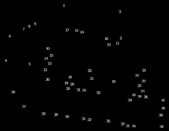
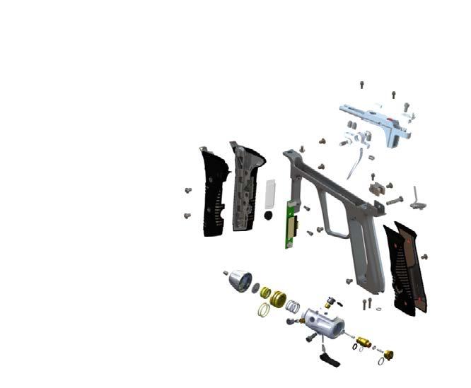
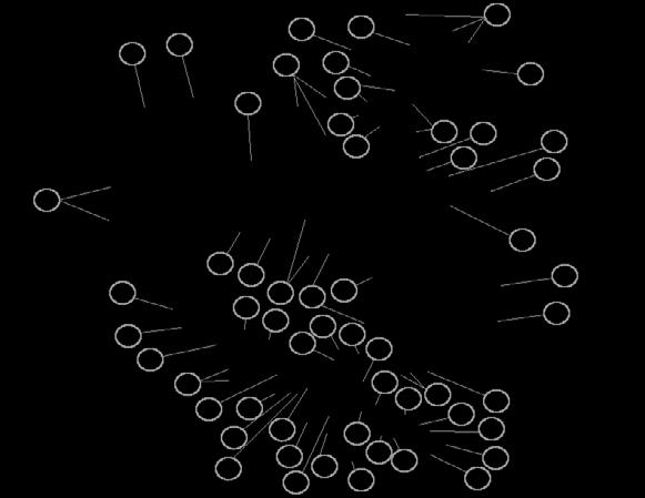
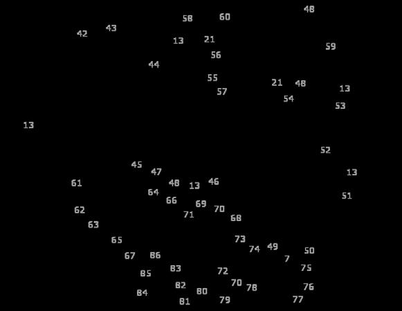
33 # PART DESCRIPTION SKU # 1 ALU Barrel Tip - Dust Black O-Ring BUNA-N 70 DUR 1mm CS X 19.5mm ID a Barrel Back.682 ID - Polished Black b Barrel Back.685 ID - Polished Black c Barrel Back.688 ID - Polished Black d Barrel Back.691 ID - Polished Black Feedneck Lever - Dust Black Feedneck Bushing Feedneck - Polished Black O-Ring BUNA-N 70 DUR -006 (.114 ID) Thumb Nut Screw BHCS 8-32 X Screw BHCS 8-32 X Body - Dust Black Eye Cover LH - Dust Black Screw BHCS 8-32 X Spring COM. 109OD X 0.250FL.010WD Rate 2.50lb/in Detent Delrin Eye Cover RH - Dust Black Feedneck Adapter - Black Screw SHCS 5-40 X Eye Board Harness LH Eye Board Harness RH Screw Set X.250 CP O-Ring BUNA-N 70 DUR 1mm CS X 5mm ID Solenoid Main Circuit board O-Ring BUNA-N 70 DUR -011 (.301 ID) O-Ring URETHANE 70 DUR -020 (.864 ID) Air Guide Bolt Tip O-Ring URETHANE 70 DUR -017 (.676ID) a Bolt (Silver) b Bolt (Soft-Shot, Red) O-Ring BUNA 90 DUR -015 (.551 ID) O-Ring URETHANE 70 DUR -016 (.614 ID) Bolt Spring Rod O-Ring URETHANE 70 DUR -013 (.426 ID) O-Ring BUNA-N 70 DUR -019 (.801 ID) O-Ring URETHANE 70 DUR -014 (.489 ID) Bolt Release Button Screw Bolt Guide - Polished Black Bolt Release Button Spring Bolt Release Button - Dust Black Foregrip LH - Black/Grey Foregrip RH - Black/Grey Screen Cover OLED Button Grip Frame - Polished Black Daughter Circuit board Screw SHCS 5-40 X Screw SHCS 5-40 X O-Ring BUNA-N 70 DUR -008 (.176 ID) Main Grip - Black/Grey Rear Body Screw SS Battery Harness Locking Block Trigger Insert Dowel Pin Bearing.156 ID X.3125 OD X Trigger - Dust Black Trigger Frame Insert - Polished Black Power Board Magnet 8mm DIA X 3mm Screw Set 10-32x.375 Cup Point Regulator Cap - Dust Black Regulator Disk Main Regulator Spring O-Ring BUNA-N 70 DUR -017 (.676 ID) Piston Piston Return Spring Regulator Body - Dust Black Regulator Filter Cap O-Ring BUNA-N 70 DUR 1.5mm CS X 6.5mm ID Regulator Filter Piston Washer Regulator Pin Regulator Seal Retainer On/Off Pin Regulator Nut O-Ring URETHANE 70 DUR -012 (.364 ID) O-Ring BUNA-N 70 DUR 1mm CS X 6.0mm ID Regulator Lever Wedge Pin Wedge Pin Spring Screw SHSS 3/16 DIA 3/8 LG 8-32 X Regulator Rubber Seal Regulator Seal Regulator OPP Spring Regulator Cover Plate Not Shown Vanquish Jewel LH - Black Not Shown Vanquish Jewel RH - Black
34 Empire Paintball Lime Kiln Rd. Neosho, MO Empire Paintball is a brand of KEE Action Sports, LLC. PATENT(S): See KEE Action Sports. All rights reserved. This KEE Action Sports product is protected by one or more United States patents. KEE Action Sports Trademarks, Designs and Copyrights are protected by one or more United States patents and International Law. For more information contact KEE Action Sports at info@keeactionsports.com LIMITED LIFETIME WARRANTY INFORMATION (ORIGINAL PURCHASE RECEIPT REQUIRED) KEE Action Sports ( KEE ) warrants that this product is free from defects in materials and workmanship for as long as it is owned by the original purchaser, subject to the terms and conditions set forth below. KEE Action Sports will repair or replace with the same or equivalent model, without charge, any of its products that have failed in normal use because of a defect in material or workmanship. KEE Action Sports is dedicated to providing you with products of the highest quality and the industry s best product support available for satisfactory play. Purchaser should register product to activate warranty. Register your product by: 1. Online at 2. Complete the product registration card (if applicable) and mail along with a copy of your receipt to Paintball Solutions, Lime Kiln Rd., Neosho, MO USA Canada WHAT THIS WARRANTY DOES NOT COVER This warranty does not cover problems resulting from abuse, the unauthorized modification or alteration of our product, problems resulting from the addition of aftermarket products and scratches or minor superficial imperfections. Due to the nature of paintball products it is important that the product be maintained by the user as indicated in the product manual to remain in good operating condition. Your Limited Lifetime Warranty will be void if you fail to maintain the product as recommended in the product instruction manual. In addition, certain parts of a product may be subject to wear through regular usage. Replacement and repair of such parts is the responsibility of the user throughout the life of the product. These parts are not covered under the Limited Warranty. Examples of this type of part include (but are not limited to) goggle lens, straps, O-Ring seals, cup seals, springs, ball détentes, batteries, hoses, drive belts, gears and any part of a product subject to continuous impact from paintballs. Hydrotesting of air cylinders is not covered under this warranty. The Limited Lifetime Warranty also does not cover incidental or consequential damages. This warranty is the sole written warranty on KEE s product and limits any implied warranty to the period that the product is owned by the original purchaser. Some states, provinces and nations do not allow the limitation of implied warranties or of incidental or consequential damages, so the above limitations or exclusions may not apply to you. This warranty gives you specific legal rights and you may also have other rights which vary from state to state, province to province, nation to nation. If you should encounter any problems with your product and you have added aftermarket parts on your product, please test it with the original stock parts before sending it in. Always unload and remove air supply before shipping markers. Do not ship your air supply tank if it is not completely empty. Shipping a pressurized air supply tank is unsafe and unlawful. Remove all batteries from products prior to shipping. This Limited Warranty gives you specific legal rights, and you may also have other rights which vary from state to state. Some states do not allow the exclusion of incidental or consequential damages. For Warranty parts, service, information or manuals in other languages, (where applicable) go to Paintball Solutions: tech@paintballsolutions.com US: Canada: Lime Kiln Rd., Neosho, MO

35 EMPIREPAINTBALL.COM Lime Kiln Rd, Neosho, MO Empire Paintball is a brand of KEE Action Sports, LLC.
TABLE OF CONTENTS INTRODUCTION... 3 GENERAL MAINTENANCE RULES FOR SAFE MARKER HANDLING...
 TABLE OF CONTENTS INTRODUCTION... 3 RULES FOR SAFE MARKER HANDLING... 4 QUICK SETUP... 5 Super Freak Barrel... 5 Vanquish Power On/Off... 6 Tank Installation... 6 Installing a Loader and Paintballs...
Yakuza OLED Series Droid & Cyborg 07 Board
 Yakuza OLED Series Droid & Cyborg 07 Board 1. Features 2. Installation 3. Board Operation 4. OLED Diagrams 5. Menu System 6. Settings 7. Recommendations FEATURES Fully functional in the MacDev Droid and
LED CONVERSION BOARD - YAKUZA SERIES EGO/GEO
 LED CONVERSION BOARD - YAKUZA SERIES EGO/GEO The LED conversion board replaces the OLED screen mini-board on your Yakuza Series board. Combined with new firmware, your board will function similarly to
WARNING OLED & BASIC MENU QUICK START
 Getting Started QUICK START WARNING The VANGUARD MARKER is not a toy. Careless or improper use, including failure to follow instructions and warnings within this Operator Manual and attached to the VANGUARD
CONTENTS. Read this entire manual before loading, or installing an air cylinder, or in any way attempting to operate the marker
 OWNER S MANUAL CONTENTS 1. Rules for Safe Marker Handling 2. Introduction and Specifications 3. Battery Replacement and Life Indicator 4. Basic Operation 5. Compressed Air/Nitrogen Supply 6. Installing
YAKUZA SERIES OLED. For the Bob Long Closer, Marq, Vice, and Protege 4C Technology by Extreme Paintball Design LLC, pat pend FEATURES
 1. Features 2. Installation 3. Board Operation 4. OLED Diagrams 5. Menu System 6. Settings 7. Recommendations YAKUZA SERIES OLED For the Bob Long Closer, Marq, Vice, and Protege 4C Technology by Extreme
O P E R A T O R S M A N U A L
 OPERATOR S MANUAL WARNING! This is not a toy. Misuse may cause serious injury or death. Eye protection designed specifically for paintball must be worn by the user and persons within range. Must be 18
Synergy Owners Manual
 Synergy Owners Manual Table of Contents Safety Guidelines...2 Quickstart Guide...3 Owners Manual...7 Field Strip Guide...11 Do s & Don ts...12 Diagrams...13 Troubleshooting Guide...15 Warranty Info...16
Cover.qxd 1/10/05 10:30 AM Page 2. user manual. diablopaintball.com
 Cover.qxd 1/10/05 10:30 AM Page 2 user manual Cover.qxd 1/10/05 10:30 AM Page 3 Table Of Contents: Page Topic(s) 1 Warning and Rules Safe Marker Handling 2 Warranty Information 3 Welcome 4 Battery Installation
Proto Matrix Musashi 3 Upgrade Manual
 Proto Matrix Musashi 3 Upgrade Manual Musashi 3 Upgrade Instructions for Proto Matrix FEATURES...3 LED INDICATOR...3 SOLID GREEN...3 SOLID RED...3 SLOW BLINKING GREEN...3 SLOW BLINKING RED...3 POWER OPERATION...3
WARNING TABLE OF CONTENTS:
 WARNING WARNING: This is not a toy. Misuse may cause serious injury or death. Eye protection designed specifically for paintball must be worn by the user and persons within range. Recommend 18 years of
O W N E R S M A N U A L E M P I R E P A I N T B A L L. C O M
 OWNER S MANUAL CONTENTS 1. Rules for Safe Marker Handling...1 2. Introduction and Specifications...1 3. Battery Replacement and Life Indicator...2 4. Compressed Air/Nitrogen Supply...2 5. Basic Operation...3
IMPORTANT CO2/ HPA AIR TANK SAFETY INSTRUCTION AND GUIDELINES. Tank valves must be installed or removed by qualified personnel.
 !WARNING! IMPORTANT SAFETY INSTRUCTION AND GUIDELINS!WARNING! IMPORTANT CO2/ HPA AIR TANK SAFETY INSTRUCTION AND GUIDELINES GETTING STARTED This Paintball Marker is NOT A TOY. Misuse can cause serious
user manual .68 CALIBER ELECTRONIC PAINTBALL MARKER Meets or exceeds ASTM standards.
 user manual TM TM TABLE OF CONTENTS: Page Topic(s) 1 Warning and Rules Safe Marker Handling 2 Warranty Information 3 Welcome 4 Initial Assembly Battery Installation 9 Attaching Propellant Source Attaching
IMPORTANT CO2/ HPA AIR TANK SAFETY INSTRUCTION AND GUIDELINES. Tank valves must be installed or removed by qualified personnel.
 !WARNING! IMPORTANT SAFETY INSTRUCTION AND GUIDELINS!WARNING! IMPORTANT CO2/ HPA AIR TANK SAFETY INSTRUCTION AND GUIDELINES GETTING STARTED This Paintball Marker is NOT A TOY. Misuse can cause serious
WARNING. Paintball Pistol. Paintball Pistol
 This lightweight assault paintball pistol is custom milled from high grade aluminum for superb balance and precision. The compact construction of this competition paintball pistol will give you a mobile
IMPORTANT CO2/ HPA AIR TANK SAFETY INSTRUCTION AND GUIDELINES. Tank valves must be installed or removed by qualified personnel.
 !WARNING! IMPORTANT SAFETY INSTRUCTION AND GUIDELINS!WARNING! IMPORTANT CO2/ HPA AIR TANK SAFETY INSTRUCTION AND GUIDELINES GETTING STARTED This Paintball Marker is NOT A TOY. Misuse can cause serious
NoX 06 Cyborg Board Instructions
 Installation: First insure that the air is off, and then refer to your markers instruction manual to put the marker in a safe, non firing condition. When removing or installing the board, user must be
MAYHEM MAYHEM OWNERS MANUAL. Paintball Guns International. Manufactured by
 MAYHEM MAYHEM OWNERS MANUAL Manufactured by Paintball Guns International Table of Contents Specifications...................... 2 Parts diagram and Listing............. 3 Description of Marker Operation.......
INTRODUCING THE G.I. SPORTZ VICTUS WARRANTY
 INTRODUCING THE G.I. SPORTZ VICTUS The G.I. Victus was created in collaboration with Bob Long Domestic Gun Developer for the last 20 years. The Marker was designed to give its user the fastest rate of
 www.empirepaintball.com 1. SAFE MARKER HANDLING IMPORTANT: Never carry your marker uncased when not on a playing field. The non-playing public and law enforcement personnel may not be able to distinguish
USERS MANUAL. Manufactured by MacDev Paintball - Australia macdev.net
 USERS MANUAL Manufactured by MacDev Paintball - Australia macdev.net Tactical Drone Users Manual Copyright Mac Developments Pty. Ltd. 2009 All rights reserved No part of this document may be copied or
O W N E R S M A N U A L
 OWNER S MANUAL THE CHOICE OF CHAMPIONS = HYPERLINK TO MORE INFORMATION INCLUDED WITH YOUR M-2 MARKER 3 Piece barrel kit (1) 14 UL Barrel tip (1).684 UL Barrel back (1).688 UL Barrel back Dye multi tool
TABLE OF CONTENT IMPORTANT HPA AIR TANK SAFETY INSTRUCTIONS AND GUIDELINES RYSE ON/OFF ASA GETTING STARTED O-RING LIST SCREW LIST MICRO SQ BOARD
 TABLE OF CONTENT 4 IMPORTANT HPA AIR TANK SAFETY INSTRUCTIONS AND GUIDELINES 22 RYSE ON/OFF ASA 6 GETTING STARTED 23 O-RING LIST 8 MICRO SQ BOARD 25 SCREW LIST 6 TRIGGER ADJUSTMENT 28 INTERNAL PARTS 7
Users Manual STANDARD, SELECT, AND LCD MODELS
 Users Manual Generation E Sports STANDARD, SELECT, AND LCD MODELS Generation E Sports 956 South Second Street Ronkonkoma, NY 11779 USA (631) 580-4377 www.matrixmarker.com GENERATION E SPORTS MATRIX OPERATORS
user manual .68 CALIBER ELECTRONIC PAINTBALL MARKER Meets or exceeds ASTM standards.
 user manual TM TM TABLE OF CONTENTS: Page Topic(s) 1 Warning and Rules Safe Marker Handling 2 Warranty Information 3 Welcome 4 Initial Assembly 6 Parts Key 7 Exploded Diagram 8 Battery Installation 9 Attaching
E-MAG TM Instruction Manual
 E-MAG TM Instruction Manual SAFETY THIS PAINTBALL MARKER IS NOT A TOY! This paintball marker should be treated as a dangerous instrument and should always be treated with respect. Never point a paintball
O W N E R S M A N U A L
 2017 OWNER S MANUAL THE CHOICE OF CHAMPIONS = HYPERLINK TO MORE INFORMATION INCLUDED WITH YOUR M-2 MARKER 3 Piece barrel kit (1) 14 UL Barrel tip (1).684 UL Barrel back (1).688 UL Barrel back Dye multi
dye Precision, Inc. USA Scripps Summit Ct. San Diego, CA P f
 O W N E R S M A N U A L dye Precision, Inc. USA 10637 Scripps Summit Ct. San Diego, CA 92131 P 858-536-5183 f 858-536-5191 GERMANY Albert Einstein Str. 2 B 77656 Offenburg, Germany P +49 (0)781 639 349
! WARNING! IMPORTANT HPA AIR TANK SAFETY INSTRUCTION AND GUIDELINES ! WARNING! IMPORTANT SAFETY INSTRUCTION AND GUIDELINES
 ! WARNING! IMPORTANT SAFETY INSTRUCTION AND GUIDELINES! WARNING! IMPORTANT HPA AIR TANK SAFETY INSTRUCTION AND GUIDELINES This Paintball Marker is NOT A TOY. Misuse can cause serious injury or death. It
Proto Paintball USA EUROPE ASIA
 Proto Paintball USA 10637 Scripps Summit Ct. San Diego, CA 92131 P 858-536-5183 F 858-536-5191 EUROPE Dye House, 7-8 Commerce Way Croydon, Surrey, CR0 4XA, United Kingdom P +44 (0) 20-8649-6330 F +44 (0)
VIBE. Quick Start Manual
 VIBE Quick Start Manual STATISTICS PLEASE READ CAREFULLY VITAL STATISTICS LENGTH/HEIGHT/WEIGHT: OPERATING PRESSURE: PAINTBALLS: POWER SOURCE: PROPELLANT: RATE OF FIRE: OPERATION: MODES OF FIRE: ANTI CHOP
PLEASE READ ALL OPERATING INSTRUCTIONS BEFORE USING THE LEGEND PAINTBALL MARKER
 PLEASE READ ALL OPERATING INSTRUCTIONS BEFORE USING THE LEGEND PAINTBALL MARKER TABLE OF CONTENTS WARNINGS Important Safety Instructions and Guidelines...page 1 OPERATING INSTRUCTIONS Turning your LEGEND
SAFETY Always wear approved safety goggles or an approved mask whenever you handle this paintball marker!
 Instruction Manual Table of Contents SAFETY... 1 COMPRESSED AIR ONLY... 2 FAST START... 3 FIRST TIME PROBLEMS... 4 PERFORMANCE... 4 LUBRICATION... 5 VELOCITY ADJUSTMENT... 5 CLEANING... 5 PAINTBALLS...
1799 Carpenter Road Oakley, California Operator s M a n u a l
 1799 Carpenter Road Oakley, California 94561 2 0 0 5 Operator s M a n u a l Table of Contents Section Page Safety.....................................................2 Warranty...................................................3
Lasoya ProMaster Board Settings
 Default Settings Lasoya ProMaster Board Settings DIP 1 DIP 2 DIP 3 DIP 4 MODE Description Off Off Off Off Semi Auto Uncapped Semi-Auto, PDS On On On On On PSP Mode PSP Ramp, 15 BPS, PDS On Default settings
FIRESTORM. Assembly Instructions. Electric Upgrade Kit for the Autococker. Designed & Manufactured by PGI
 FIRESTORM Electric Upgrade Kit for the Autococker Assembly Instructions Designed & Manufactured by PGI Table of Contents Introduction 1 Safety 1 Parts Diagram 2 Parts Diagram Listing 2 Getting Started
This Manual was downloaded from the Paintball Gun Service Manuals list.
 This Manual was downloaded from the Paintball Gun Service Manuals list. Proto Paintball USA 10637 Scripps Summit Ct. San Diego, CA 92131 P 858-536-5183 F 858-536-5191 EUROPE UNITED KINGDOM Dye House, 7-8
ProMaster Troubleshooting Guide
 ProMaster Troubleshooting Guide Always read your owner's manual before operating or doing maintenance on your ProMaster marker. The manual contains in-depth maintenance and setup information. Always remove
BT_SA-17_Manual.qxp 3/11/10 9:54 AM Page C
 BT_SA-17_Manual.qxp 3/11/10 9:54 AM Page C OWNER S MANUAL BT_SA-17_Manual.qxp 3/11/10 9:54 AM Page D CONTENTS 1. Rules for Safe Marker Handling..............................1 2. Introduction and Specifications..............................1
TABLE OF CONTENTS Section Page Safety Warranty
 GEN4 I N T I M I D A T O R A L E G E N D R E B O R N TABLE OF CONTENTS Section Page Safety..............................................................................2 Warranty............................................................................3
Proto Paintball USA EUROPE ASIA
 Proto Paintball USA 10637 Scripps Summit Ct. San Diego, CA 92131 P 858-536-5183 F 858-536-5191 EUROPE Unit 1, ZK Park, 23 Commerce Way Croydon, Surrey CRO 4ZS United Kingdom P +44 (0) 20-8649-6330 F +44
SHOCKER RSX OWNER S MANUAL PLEASE READ CAREFULLY 1
 SHOCKER RSX OWNER S MANUAL WWW.SHOCKERPAINTBALL.COM 1 QUICK START Velocity must be measured and adjusted to below 300 feet per second (91.4 PLEASE meters per READ second) CAREFULLY before each session
TABLE OF CONTENTS IMPORTANT SAFETY INSTRUCTIONS AND GUIDELINES... PAGE 02 QUICK REFERENCE... PAGE 04 BOARD SETTINGS AND FUNCTIONS...
 D M 9 O W N E R S M A N U A L TABLE OF CONTENTS IMPORTANT SAFETY INSTRUCTIONS AND GUIDELINES......................... PAGE 02 QUICK REFERENCE........................................................ PAGE
BUILT TO WIN PAINTBALL LOADER SPIRE III MANUAL
 BUILT TO WIN PAINTBALL LOADER SPIRE III MANUAL SPIRE III SETUP Thank you for purchasing the Virtue Spire III paintball loader. This manual covers all aspects of your Spire III loader. It is recommended
OPERATING INSTRUCTIONS V 5.3
 1 OPERATING INSTRUCTIONS V 5.3 DM 06/ 07 EGO 06/ 07 ION /SP8 MINI Proto Matrix 07 Proto Rail Shocker Seventh Element, Inc WARNING Failure to follow directions may result in damage to board. Do not pull
Paintball Marker. User s Manual. 530 South Springbrook Road Newberg, OR 97132
 Paintball Marker User s Manual 530 South Springbrook Road Newberg, OR 97132 Component Concepts, Inc., 530 South Springbrook Road, Newberg, OR 97132 Phone: (503) 554-8095 Fax: (503) 554-9370 www.phantomonline.com
Shocker Sport TM Manual. Includes: Shocker Sport 4X4 TM and Shocker Sport Turbo TM
 Shocker Sport TM Manual Includes: Shocker Sport 4X4 TM and Shocker Sport Turbo TM WARNING! The Shocker Sport TM Paintball Marker is not a toy. Misuse or careless use may cause serious injury or death.
stormrider Instructions for Use Version 08/2017
 stormrider EN Instructions for Use Version 08/2017 INTRODUCTION DESCRIPTION SAFETY INSTRUCTIONS TECHNICAL DATA HANDLING & OPERATION CARE & MAINTENANCE TROUBLESHOOTING DESCRIPTION Front Sight Barrel Rear
DM8 manual.qx6 10/8/07 5:14 PM Page 1
 DM8 manual.qx6 10/8/07 5:14 PM Page 1 DYE Precision, Inc. USA 10637 Scripps Summit Ct. San Diego, CA 92131 P 858-536-5183 F 858-536-5191 EUROPE Unit 1, ZK Park, 23 Commerce Way Croydon, Surrey CRO 4ZS
MODEL 1410 OWNER S MANUAL
 2111 S. 8th, Rogers, Ar 72758 U.S.A. (501) 636-1200 Fax (501)636-0573 http://www.brasseagle.com THIS BOOKLET CONTAINS: Safety Information Warranty Registration Annotated Diagram Operating Instructions
Race Screen: Figure 2: Race Screen. Figure 3: Race Screen with Top Bulb Lock
 Eliminator Competition Stand Alone Mode - Instruction Manual Main Menu: After startup, the Eliminator Competition will enter the Main Menu. Press the right/left arrow buttons to move through the menu.
BUSHMASTER 2000 / 2K2 (LCD) MANUAL. BushMaster 2000 Overview
 MANUAL. BushMaster 2000 Overview") BUSHMASTER 2000 / 2K2 (LCD) MANUAL BushMaster 2000 Overview The BushMaster 2000 is a quality marking instrument specially designed to meet the needs of the professional style tournament player. The BushMaster
BUSHMASTER 2000 / 2K2 (LCD) MANUAL BushMaster 2000 Overview The BushMaster 2000 is a quality marking instrument specially designed to meet the needs of the professional style tournament player. The BushMaster
O p e r a t o r s M a n u a l A - B o m b D a r k R i p p e r 2 R i p p e r ivera R obert R by esign D & Photography
 O p e r a t o r s M a n u a l A-Bomb Dark Ripper 2 Ripper 2.5 Photography & Design by Robert Rivera - 305.819.1009 Table of Contents Section Page Safety.....................................................2
PM8 manual-final.qx6 10/4/07 1:06 PM Page 1
 PM8 manual-final.qx6 10/4/07 1:06 PM Page 1 Proto Paintball USA 10637 Scripps Summit Ct. San Diego, CA 92131 P 858-536-5183 F 858-536-5191 EUROPE Unit 1, ZK Park, 23 Commerce Way Croydon, Surrey CRO 4ZS
User Instruction Manual
 User Instruction Manual 4500 psi Air Compressor Ver 2, 1.18 Contents Parts Included...3 Assembly Instructions...3-5 Operation Instructions...6-7 Oil Change Intervals...8 Air Filter Replacement...9 Setting
BT PAINTBALL DESIGNS, INC. 570 MANTUA BLVD., SEWELL, NJ
 Rip Clip Manual_2.qxp 4/15/08 11:00 AM Page a BT PAINTBALL DESIGNS, INC. 570 MANTUA BLVD., SEWELL, NJ 08080 WWW.BTPAINTBALL.COM Rip Clip Manual_2.qxp 4/15/08 11:00 AM Page b BT Paintball would like to
INDEX. About this Manual. Section 1 - Orientation. Section 2 - Installation. Section 3 - Quick Set-up.
 OPERATING MANUAL About this Manual This manual contains the installation and operating instructions for the Eclipseblade E2 Electronic grip frame. IMPORTANT: If you are installing the Eclipseblade E2 electronic
ELIMINATOR COMPETITION DRAG RACE Program Manual Firm Ver 4.11
 ELIMINATOR COMPETITION DRAG RACE Program Manual Firm Ver 4.11 The Portatree Eliminator Super 2000 Competition Track Timer can be used with an IBM Compatible Personal Computer connected through Com Port
Play Safe. Safety. Instruction Manual. Warning. Rebel Specifications
 Operation Guide Instruction Manual Congratulations on your purchase of the 32 Degrees Rebel Xtreme semi-auto. Before you use this marker, please read this manual in its entirety. Please follow all safety
Rip Clip Manual_2.qxp 4/15/08 11:00 AM Page c
 Rip Clip Manual_2.qxp 4/15/08 11:00 AM Page b Rip Clip Manual_2.qxp 4/15/08 11:00 AM Page c Rip Clip Manual_2.qxp 4/15/08 11:00 AM Page 1 BT Paintball would like to thank you for your purchase of the BT
WARNING OWNER S MANUAL WARSENSOR WSP PAINTBALL PISTOL
 WARSENSOR WSP PAINTBALL PISTOL OWNER S MANUAL WARNING WARSENSOR PAINTBALL MARKERS ARE NOT A TOY. ANY MISUSE MAY CAUSE SERIOUS INJURY OR DEATH. THE USER AND ANY PERSON WITHIN RANGE MUST WEAR EYE PROTECTION
Quick Start Guide. A. Hardware installation B. Software installation C. Start the software for the first time D. Do your first measurement
 Quick Start Guide This Quick Start Guide describes the hardware and software installation process and the Measurement feature in a simple way. Please follow the sequence of the steps to avoid problems
SAFETY WARNING MUST READ
 Airgun Designs Inc. Table of Contents SAFETY...1-2 COMPRESSED AIR ONLY... 2 FAST START... 3 LvL 10 ANTI-CHOP SYSTEM... 4 LOADER...4 PERFORMANCE... 4 LUBRICATION... 4 VELOCITY ADJUSTMENT... 5 BLOW-OFF VALVE...
Pilot JAVA 9.6V RECHARGEABLE BATTERY & CHARGER INCLUDED. Kingman Group Live Oak Avenue, Baldwin Park, CA 91706, U.S.A. Toll-free 888.
 Pilot Kingman Group 14010 Live Oak Avenue, Baldwin Park, CA 91706, U.S.A. Toll-free 888.KINGMAN www.kingman.com JAVA 9.6V RECHARGEABLE BATTERY & CHARGER INCLUDED 14010 Live Oak Avenue, Baldwin Park, CA
TABLE OF CONTENTS DM4 OWNER S MANUAL QUICK REFERENCE...PAGE 02 IMPORTANT SAFETY INSTRUCTIONS AND GUIDELINES...PAGE 03
 < < S P E C S > > WEIGHT [.3 LBS] WIDTH [.37 ] LENGTH [9.7 ] HEIGHT [8. ] EFFICIENCY [,00 SHOTS OFF 68CU 400PSI] BATTERY LIFE [40,000 SHOTS] OPERATING PRESSURE [7PSI] CYCLE PRESSURE [7PSI] MAX RATE OF
PROPORTIONING VALVE. Model 150 INSTRUCTION MANUAL. March 2017 IMS Company Stafford Road
 PROPORTIONING VALVE Model 150 INSTRUCTION MANUAL March 2017 IMS Company 10373 Stafford Road Telephone: (440) 543-1615 Fax: (440) 543-1069 Email: sales@imscompany.com 1 Introduction IMS Company reserves
TABLE OF CONTENTS 2014 DM SERIES OWNER S MANUAL IMPORTANT SAFETY INSTRUCTIONS AND GUIDELINES... PAGE 02 QUICK REFERENCE... PAGE 04
 2014 DM SERIES OWNER S MANUAL TABLE OF CONTENTS IMPORTANT SAFETY INSTRUCTIONS AND GUIDELINES... PAGE 02 QUICK REFERENCE... PAGE 04 BOARD SETTINGS AND FUNCTIONS... PAGE 06 REACH AIRPORT... PAGE 12 INCLUDED
Operations Manual for The
 Operations Manual for The WARNING: The paintball marker, which you have purchased, is not a toy. Misuse or carelessness may cause serious injury or death. Eye and ear protection designed specifically for
WELCOME TO THE REVOLUTION
 USER GUIDE WELCOME TO THE REVOLUTION THANK YOU FOR CHOOSING THE GCQUAD We listened to what you wanted - and created the most accurate, versatile and game-enhancing ball and club analysis solution available
IMPULSE. Operation and adjustment instructions IPS136 - SOLENOID CLAMP PIN IPS105P - IMPULSE SOLENOID CLAMP SOL4SHKNRV - SOLENOID VALVE
 IMPULSE Operation and adjustment instructions CKET CUPPED SCREW IPS136 - SOLENOID CLAMP PIN S S IPS105P - IMPULSE SOLENOID CLAMP SOL4SHKNRV - SOLENOID VALVE PS153 - HEAT SHRINK TUBE ORN0201070B ORN0401070BU
unconventional-airsoft.com
 unconventional-airsoft.com Congratulations on your new digital fire control computer! This unit will change the way you use and look at your electric gun. With this short document, you will know all you
TABLE OF CONTENTS SAFETY FIRST!...3 BASIC OPERATION...4 ADJUSTMENTS...5. Cocking Pressure...5. Three-Way Valve Adjustment...6
 TABLE OF CONTENTS SAFETY FIRST!...3 BASIC OPERATION...4 ADJUSTMENTS...5 Cocking Pressure...5 Three-Way Valve Adjustment...6 External Three-Way adjustment...6 In-Line Regulator...6 Ram to Cocking Block
444C DUAL PERFORMANCE VALUE PACK
 (Chrome) PART NO. 44432 IMPORTANT: It is essential that you and any other operator of this product read and understand the contents of this manual before installing and using this product. SAVE THIS MANUAL
Autococker Marker Manual
 Autococker Marker Manual Autococker Trilogy Select-Fire Manual WORR GAME PRODUCTS, LLC. TRILOGY AUTOCOCKER OWNERS MANUAL WARNING: This Always is not wear a toy. paintball Misuse approved may cause eye
FX IMPACT OWNER S MANUAL
 made in sweden FX IMPACT OWNER S MANUAL Warranty Information All FX Airguns carry a One Year Warranty against faulty workmanship and defective materials. If it becomes necessary, first contact the dealer
TABLE OF CONTENTS. AIR SOURCE : CO2/HPA ONLY (not included)
") Owner s Manual INCLUDES -.68 CALIBER CONQU3ST PAINTBALL MARKER - 10.5 ONE PIECE BARREL (AUTOCOCKER THREAD) - SPARE PARTS KIT - TOOL KIT - BARREL BLOCKING DEVICE AIR SOURCE : CO2/HPA ONLY (not included)
Owner s Manual INCLUDES -.68 CALIBER CONQU3ST PAINTBALL MARKER - 10.5 ONE PIECE BARREL (AUTOCOCKER THREAD) - SPARE PARTS KIT - TOOL KIT - BARREL BLOCKING DEVICE AIR SOURCE : CO2/HPA ONLY (not included)
WARNING WARNING WARNING WARNING
 WARNING ADHERE STRICTLY TO THESE AND ALL OTHER SAFETY INSTRUCTIONS AND GUIDELINES! WARNING ADHERE STRICTLY TO THESE AND ALL OTHER SAFETY INSTRUCTIONS AND GUIDELINES! WARNING 2. 01. The Eclipse Geo is not
9A5N Solid State CW Paddle
 9A5N Solid State CW Paddle User manual Table of contents: 1. General description 2. Before you begin 3. Finger piece and/or battery installation 4. Interconnection 5. Lever(s) sensitivity adjustment 6.
WARNING continued: 14. Never put any body parts or foreign objects into the breech or feed tube. 15. Always use the supplied barrel cover when your
 owner s manual 1 Owner s Manual 2 WARNING: 1. The DP G5 SPEC-R is NOT A TOY. Treat it with the same respect and care you would a firearm. 2. Carelessness, Misuse, and failure to adhere to the warning and
tel: UK +44 (0) tel: USA web:
 tel: USA web:") > MANUFACTURED IN ENGLAND BY PLANET ECLIPSE < tel: UK +44 (0)161 872 5572 tel: USA 401 247 9061 e-mail: info@planeteclipse.com web: www.planeteclipse.com Operating Manual Introduction About this Manual
> MANUFACTURED IN ENGLAND BY PLANET ECLIPSE < tel: UK +44 (0)161 872 5572 tel: USA 401 247 9061 e-mail: info@planeteclipse.com web: www.planeteclipse.com Operating Manual Introduction About this Manual
CONSUMER MODEL INSTALLATION GUIDE
 CONSUMER MODEL INSTALLATION GUIDE System requirements Windows System Requirements To use your TOMI and its software, your system should have: A Microsoft Windows compatible PC with a Pentium IV processor
Paintball Marker. User s Manual. Direct Feed. SC: Stock Class. VSC: Vertical Air Stock Class. 530 South Springbrook Road Newberg, OR 97132
 Paintball Marker User s Manual Direct Feed SC: Stock Class 530 South Springbrook Road Newberg, OR 97132 VSC: Vertical Air Stock Class www.phantomonline.com Component Concepts, Inc., 530 South Springbrook
FireHawk M7 Interface Module Software Instructions OPERATION AND INSTRUCTIONS
 FireHawk M7 Interface Module Software Instructions OPERATION AND INSTRUCTIONS WARNING THE WARRANTIES MADE BY MSA WITH RESPECT TO THE PRODUCT ARE VOIDED IF THE PRODUCT IS NOT USED AND MAINTAINED IN ACCORDANCE
MECH-TECH SYSTEMS CCU MODEL FOR GLOCK PISTOLS
 MECH-TECH SYSTEMS CCU MODEL FOR GLOCK PISTOLS Operation & Maintenance Manual Read and understand this manual before attempting to use this product. If you have any questions call: 1-866-433-2122 www.mechtechsys.com
OWNER S MANUAL
 OWNER S MANUAL WWW.EMPIREBATTLETESTED.COM CONTENTS 1. RULES FOR SAFE MARKER HANDLING 1 2. INTRODUCTION AND SPECIFICATIONS 1 3. GETTING STARTED 1 4. FIRING YOUR MARKER 3 5. VELOCITY ADJUSTMENT 3 6. ACCESSORY
USER MANUAL: ENGLISH EDITION
 USER MANUAL: ENGLISH EDITION WARNING! W ADHERE STRICTLY TO THESE AND ALL OTHER SAFETY INSTRUCTIONS AND GUIDELINES! Please read and understand all instruction manuals before use. The Eclipse ETEK5 is not
TIPPMANN 98 CUSTOM. Owner s Manual CO2 POWERED PAINTBALL GUN
 TIPPMANN PNEUMATICS, INC. Get Your ur Heart t Pound unding With h A Tippmann! WARNING: This paintball marker/gun is not a toy nor is it intended for unsupervised use by persons under the age of 18 years.
IMPORTANT SAFETY GUIDELINES !CAUTION!
 USERS MANUAL TABLE OF CONTENTS IMPORTANT SAFETY GUIDELINES 1 OPERATION GUIDE / START UP 2 CO2 / COMPRESSED AIR TANK 3-4 ELECTRONICS & SETTINGS 5-6 BATTERY CHARGING 7-8 VELOCITY ADJUSTMENT 9 SHOULDER STOCK
TR Electronic Pressure Regulator. User s Manual
 TR Electronic Pressure Regulator Page 2 of 13 Table of Contents Warnings, Cautions & Notices... 3 Factory Default Setting... 4 Quick Start Procedure... 5 Configuration Tab... 8 Setup Tab... 9 Internal
400C & 450C DUAL PERFORMANCE VALUE PACKS
 (Chrome) PART NO. 40013 (Silver) PART NO. 45012 (Chrome) PART NO. 45013 IMPORTANT: It is essential that you and any other operator of this product read and understand the contents of this manual before
O W N E R S M A N U A L
 O W N E R S M A N U A L w w w. d a n g e r o u s p o w e r. c o m A WORD FROM our engineers and design team Our challenge was to blend the art of metal sculpture with masterful electronics in a package
RULES FOR SAFE MARKER HANDLING
 ICD PROMASTER MANUAL-REV 6/5/05 6:00 PM Page RULES FOR SAFE MARKER HANDLING ) Treat every marker as if it were loaded. ) Never look down the barrel of a paintball marker. ) Keep your finger off the trigger
DM7 OWNER S MANUAL TABLE OF CONTENTS INCLUDED WITH YOUR DM7 ADDITIONAL RECOMMENDED TOOLS QUICK REFERENCE...PAGE 02
 DM OWNER S MANUAL TABLE OF CONTENTS QUICK REFERENCE.............................................................................................................PAGE 0 IMPORTANT SAFETY INSTRUCTIONS AND
NOT A TOY. ADULT SUPERVISION REQUIRED. MISUSE OR CARELESS USE MAY CAUSE SERIOUS INJURY OR DEATH.DANGEROUS UP TO 350 YARDS (320 METER).
.") Caution: NOT A TOY. ADULT SUPERVISION REQUIRED. MISUSE OR CARELESS USE MAY CAUSE SERIOUS INJURY OR DEATH.DANGEROUS UP TO 350 YARDS (320 METER). This air rifle is primarily intended for adult use. However,
Caution: NOT A TOY. ADULT SUPERVISION REQUIRED. MISUSE OR CARELESS USE MAY CAUSE SERIOUS INJURY OR DEATH.DANGEROUS UP TO 350 YARDS (320 METER). This air rifle is primarily intended for adult use. However,
Remains 2006 By. Alien Warning:
 Remains 2006 By Alien Warning: This is a dangerous piece of sporting equipment. Like any air rifle or air pistol, it can cause injury or death. By purchasing this paintball marker you assume all liability.
CAUTION: READ ALL WARNINGS BEFORE USING OR ATTEMPTING ANY WORK ON YOUR MARKER. SHOULD YOU BE UNSURE AT ANY POINT, STOP AND SEEK PROFESSIONAL SUPPORT.
 Insight NG Bob Long Technologies 209-293- 4440 www.boblongdirect.com 2 Table of Contents Warning... 3 Warranty... 3 Introducing the Insight NG... 4 Ready for the Field... 4 Maintenance Intervals... 5 Quick
PROCESSOR UNIT - V2. Spring limit M180 and ROF 25bb/s
 21 st century electronics for AEG weapons PROCESSOR UNIT - V2 Spring limit M180 and ROF 25bb/s Installation of this device leave to expert He must know how to solder and disassemble airsoft gun Never use
SAFETY RULES WARNING: READ THESE SAFETY RULES & OPERATORS MANUAL BEFORE HANDLING YOUR FIREARM
 SAFETY RULES WARNING: READ THESE SAFETY RULES & OPERATORS MANUAL BEFORE HANDLING YOUR FIREARM Never point a firearm at anyone and always keep the muzzle pointed in a safe direction. Always treat all firearms
200 PSI COMPRESSORS - MODEL NUMBERS
 200 PSI COMPRESSORS - MODEL NUMBERS 380C AIR COMPRESSOR KIT PART NO. 38033 480C AIR COMPRESSOR KIT PART NO. 48043 380C 480C IMPORTANT: It is essential that you and any other operator of this product read