TRAINING RESOURCES MARITIME INSTITUTE
|
|
|
- Harry Mosley
- 5 years ago
- Views:
Transcription

1 TRAINING RESOURCES MARITIME INSTITUTE NAVIGATION GENERAL All rights reserved. No part of this publication may be reproduced in any form without permission in writing from the Maritime Institute. All references contained in this publication have been compiled from sources believed to be the most recent and reliable. Published by Training Resources DBA Maritime Institute 3980 Sherman St., Ste.100 San Diego, CA Phone Toll Free Visit our website at
2 ii
3 AUTHORS Alexander F. Hickethier MBA was Maritime Institute s Vice President of Curriculum Development and Cooperative Degree programs. He is approved by The U.S.C.G. National Maritime Center to teach many upper and lower levels Maritime courses from Able Seaman through 2nd Mate Unlimited. Mr. Hickethier is a retired United States Navy Senior Chief Quartermaster and holds a Bachelor of Arts and Master of Business Administration from San Diego's National University. He also holds California Community College Teaching Credentials in Business and Industrial Management. Kevin W. Baldwin BS is Training Resources Maritime Institute s Operations Officer, Lead Instructor for the International Yacht Master Courses and Hands On Training. He holds a U.S.C.G. Master 100 ton Credential and an International Yacht Master 200 Tons Instructor and Examiner Certificate. He is approved by The U.S.C.G. National Maritime Center to teach many upper and lower level Maritime courses from Able Seaman through 2nd Mate Unlimited. Before retiring from the United States Navy, he attained the rank of Lieutenant Commander (Deck LDO 6210) and Master Chief Quartermaster QMCM SS/DV. Mr. Baldwin holds a Bachelor of Science degree from the University of Southern Illinois in Workforce Education and Curriculum Development Matthew K. Gallwas AA is Training Resources Maritime Institute s Lead Instructor for the Master/Mate Upper Tonnage Courses. He holds a U.S.C.G. Master 100 ton Credential and an International Yacht Master 200 Tons Certificate. He is approved by The U.S.C.G. National Maritime Center to teach many upper and lower level Maritime courses from Able Seaman through 2nd Mate Unlimited. He retired from the United States Navy after 20 years of service with the majority of service on small Naval Special Warfare vessels and amphibious landing craft, he holds an Associate Degree in Geographic Information Systems (cartographer) from San Diego s Mesa College. Stuart T. Sheppard A former instructor who holds a U.S.C.G. Master 100 ton Credential. He retired from the United States Navy after 26 years of service. During his time in the Navy, he served as: Departmental Leading Chief Petty Officer on the USS Nimitz (CVN-68); the Director and Training Officer of Seaman Apprenticeship Training and Boatswain's Mate "A" School at the Center for Surface Combat Systems, Naval Training Center, Great Lakes, IL; and Instructor and Craftmaster for the Seamanship and Navigation Department of the U.S. Naval Academy Copyright Training Resources DBA Maritime Institute All rights reserved. No part of this book covered by the copyright herein may be reproduced or copied in any form or by any means without the written permission of the copyright holder, except for use of brief quotations embodied in critical articles and reviews. For information contact the publisher. Every effort has been made to assure that this book is accurate, current, and complete as of the date of publication. However, as in the case of all human endeavors, there can be no guarantee that this work does not contain errors or omissions. Therefore, the prudent mariner will not rely only on this or any other single source when guiding their vessel. Please report any errors or omissions to the publisher. Published by: ISBN Published by Training Resources DBA Maritime Institute 3980 Sherman St., Ste.100 San Diego, CA Phone Toll Free Visit our website at iii
4 FOREWORD Training Resources DBA Maritime Institute has developed this series of training manuals to assist the Merchant Mariner in passing the U.S. Coast Guard Licensing Examinations, from Operator of Uninspected Passenger Vessels (Six Pack) to Master Unlimited Oceans. The training manuals are modular in design and incorporate theory, practical exercises and actual U.S. Coast Guard examination questions. As the Mariner progresses from one license level to the next, the appropriate information is provided. A description of each manual follows: Able Seaman Book 1 Shiphandling & Seamanship This book provides an in-depth understanding of Aids to Navigation; Shiphandling; Marlinespike Seamanship; Rigging; Cargo Handling Equipment and Stowage; Cargo Handling Rigs; Anchoring; Towing; Liferafts; Ship Construction; Compass and Watchstanding. Able Seaman Book 2 Marine Safety This book provides an in-depth understanding of the Rules of the Road; Marine Pollution & Oil Pollution; Publications and Regulations; Firefighting and Prevention; Damage Control; Safety; and Drills and Emergencies. Captain Course 100 Ton Deck General This book provides an in-depth understanding of the Code of Federal Regulations; Basic Shiphandling and Deck Seamanship; Anchoring; Safety; Drills and Emergencies; Life Rafts and Survival; Firefighting and Prevention; Marine and Oil Pollution; and Principles of Stability. Captain Course 100 Ton Navigation General In this book, we provide concise treatment of the Rules of the Road; Communications; Aids to Navigation; Coast Pilot; Tides and Currents; Weather; Advance Navigation; and Electronic Navigation. Captain Course 100 Ton Basic Navigation This book covers How to Read a Nautical Chart; Latitude and Longitude; Plotting Positions; Laying Out Courses and Measuring Distances; Determining the Course Made Good (CMG); Time; Determining Distance, Speed and Time (60 D ST); Dead Reckoning (DR); Determining Speed Made Good (SMG); Estimated Time of Arrival (ETA); Introduction to Magnetic Compass; Determining Ship s Deviation from a Range; Determining Position by Bearings (3 LOP Fix); Determining the Set and Drift; and Determining the Course to Steer for a Known Set and Drift. Master 200 Ton Upgrade Student Workbook This book provides study materials, formulas and actual United States Coast Guard test questions to prepare the student for the U.S.C.G. Master 200 Ton Upgrade General Safety and Navigation Plotting exams. Topics include: a study guide with General Safety questions; Stability calculations; Tide and Current calculations; Special Bearing exercises; Chart Reading exercises and Chart Plotting exercises to get the student familiar with chart numbers: 12221TR Chesapeake Bay; 12354TR Long Island Sound and 13205TR Block Island Sound. iv
5 TRAINING RESOURCES MARITIME INSTITUTE NAVIGATION GENERAL Contents Course Schedule ii Examination Procedures iii Chapter 1 Rules of the Road 1-1 Rules of the Road Questions 1-15 Rules of the Road Diagrams 1-44 Rules of the Road Answers 1-50 Chapter 2 Communications 2-1 Communications Questions 2-23 Communications Answers 2-26 Chapter 3 Aids to Navigation 3-1 Buoy Page 3-13 Terminology 3-26 Aids to Navigation Questions 3-29 Aids to Navigation Diagrams 3-34 Aids to Navigation Answers 3-35 Chapter 4 U.S. Coast Pilot 4-1 Coast Pilot Questions 4-12 Coast Pilot Answers 4-13 Chapter 5 Tides and Currents 5-1 Tides and Currents Questions 5-17 Tides and Currents Answers 5-19 Chapter 6 Advance Navigation 6-1 Advanced Navigation Questions 6-16 Advanced Navigation Answers 6-17 Chapter 7 Electronic Navigation 7-1 Electronic Navigation Questions 7-19 Electronic Navigation Answers 7-20 Chapter 8 Weather 8-1 Weather Questions 8-28 Weather Diagrams 8-32 Weather Answers 8-33 v
6 TRAINING RESOURCES MARITIME INSTITUTE COURSE SCHEDULE 2018 Master/Mate Near Coastal or Inland of Not More Than 100 Gross Tons Operator of Uninspected Passenger Vessels HOURS DAY ONE DAY TWO DAY THREE DAY FOUR DAY FIVE DAY SIX DAY SEVEN DAY EIGHT DAY NINE DAY TEN Registration L-6 Sound & Light Signals Navigation Rules Review C-6-Time C-7 60D ST Navigation Rules Review C-11 Compass Week 1 Course & Rules Review C-13- Position by 3 LOP Navigation Rules Review C-14 Set & Drift Navigation Rules Review C-15 Course to Steer for Set & Drift Navigation Rules Review L-23, L-24 Adv. Nav Electronic Nav Course Review Exam BREAK ****** ****** ****** ****** ****** ****** ****** ****** ****** ****** L-1 Intro to Nav. Rules L-2 Conduct of Vessels L-6 cont d L-7 Penalty Provisions C-8 DR C-9 SMG C-10 ETA C-12 Deviation from a range C-16 cont d Classroom Charting assignment C-16 cont d Classroom Charting assignment C-16 cont d Classroom Charting assignment C-16 Classroom Charting assignment Course Review cont d Exam L-3 Conduct of Vessels in Sight LUNCH ****** ****** ****** ****** ****** ****** ****** ****** ****** ****** L-3 cont d L-4 Conduct in Restricted Visibility L-5 Lights & Shapes L-8 Comms C-1 Nautical Chart C-2 Lat&Long C-3 Plot posit L-9 CFR s L-10 Deck Seamanship/ Marlinspike L-11 Aton and Light List L-14 Ship Handling L-16 Safety L-17 Drills and Emergencies L-19 Fire Fighting L-20 Oil Pollution & MARPOL C-16 cont d L-22 Weather Charting Review Practice Exam Exam BREAK ****** ****** ****** ****** ****** ****** ****** ****** ****** ****** L-5 cont d C-4 Measuring Cse & Dist C-5 CMG L-10 Deck Seamanship/ Marlinspike cont d L-12 Coast Pilot 13 Tides and Currents L-15 Anchoring L-18 Life Rafts and Survival Gear L -21 Trim and Stability L-22 cont d L-10 cont d Knot Tying Practice Exam cont d Exam vi
7 EXAMINATION PROCEDURES Master/Mate Near Coastal or Inland of Not More Than 100 Gross Tons Operator of Uninspected Passenger Vessels The exam for this course consists of five modules: 1). Rules of the Road Test will consist of 50 questions on Inland and International Rules. Passing Grade is 90%. 2). Deck General Test will consist of 50 questions on: Code of Federal Regulations, Seamanship, Boat Handling Marine Pollution, Lookouts and Anchoring. Passing Grade is 70%. 3). Deck Safety Test will consist of 50 questions on: Communications, Stability, Drills and Emergencies, Towing, Liferaft and Survival, Safety, Firefighting and Boat Handling. Passing Grade is 70%. 4). Navigation General Test will consist of 50 questions on: Weather, Aids to Navigation, Tides, Currents, Coast Pilot, Advance navigation, Electronic Navigation and the Magnetic Compass. Passing Grade is 70%. 5). Chart Test will consist of 10 plotting questions. Passing Grade is 90%. Students must complete all classroom requirements before any test can be administered. All exams must be completed by 4:00 p.m. on the final exam day. A test cycle consists of all five modules. If needed, students may have three opportunities to pass each module, once each cycle. Two modules must be taken per day, with two days to complete all five modules for each cycle. All modules within a cycle must be completed before the next cycle may begin. Instructor counseling is mandatory prior to any retest. Any modules not completed within the two-day limit will be considered a fail and the next cycle will start. All cycles must be completed within 90 days. If any module is failed three times or the 90-day limit is exceeded, all previous tests will be void and the test cycles will start again. All modules must be re-tested and are subject to a testing fee. If a student wishes to retake the entire 80-hour course again within one year s time, all previous tests will be void and the test cycle will start again. The cost of the course is free, however, a testing fee will be charged. Note: Since all information is subject to change, please check with the office staff for confirmation. vii
8 viii
.")
9 TRAINING RESOURCES MARITIME INSTITUTE NAVIGATION GENERAL CHAPTER 1 RULES OF THE ROAD U. S. Coast Guard Navigational Rules and Regulations Handbook contains the International Regulations for Prevention of Collision at Sea, 1972 COLREGS). It also contains the Inland Navigation Rules, which were enacted by law on 24 December 1980 and became effective for all Inland waters except the Great Lakes on 24 December The Inland Rules became effective on the Great Lakes on 1 March Some differences do remain between the International and Inland Rules. The side by side presentation of the Rules will allow mariners to determine those differences
10 Instructional Text: U. S. Coast Guard Navigation Rules and Regulations Handbook (Separate Book) Excerpts & Extracts from U. S. Coast Guard Navigation Rules and Regulations Handbook... Page 3-15 Questions... Page Diagrams& Illustrations... Page Answers... Page 53 Classroom Question Sheet... Page 54 U.S.C.G. NAVIGATION CENTER has an online Practice Your NAVRULES review section including U.S.C.G. questions at: Historical Milestones (Navigational Rules) 1838-US steam boats were required to carry one or more signal lights from sunset to sunrise 1846-London (Steam Navigation Act of 1846) 1848-UK steam vessels display red & green lights with white mast light 1849-US adopts UK lights (1848) 1863-UK & France implement new and more comprehensive navigational rules 1864-US adopts UK/French rules of New set of international rules (includes inland) 1889-First international maritime conference to consider regulations for preventing collisions 1894-US enacts navigational rules for Great Lakes 1940-US enacts the Motorboat Act of 25 April SOLAS Conference recognizes radar 1960-SOLAS (early & substantial action to avoid close quarter situations in restricted visibility) Unifying U.S. rules to align with COLREGS 1977-COLREGS go into force 1980-Inland Navigational Rules Act of
11 This section of the text book contains extracts of the U. S. Coast Guard Navigation Rules and Regulations Handbook. This section should be used as a training supplement to the information contained in U. S. Coast Guard Navigation Rules and Regulations Handbook. Structure of U. S. Coast Guard Navigation Rules. U. S. Coast Guard Navigation Rules is comprised of five parts followed by five annexes. The five parts contain the Rules and the annexes contain technical data, pilot rules and amplifying information. Part A General Rules 1 through 3 Part B Steering and Sailing Rules 4 through 19 Part C Lights and Shapes Rules 20 through 31 Part D Sound and Light Signals Rules 32 through 37 Part E Exemptions Rule 38 Annex I Positing and Technical Details of Lights and Shapes Annex II Additional Signals for Fishing Vessels Fishing in Close Proximity (International) Annex III Technical Details of Sound Signal Appliances Annex IV Distress Signals Annex V Pilot Rules (Inland) International Rules The Convention on the International Regulations for Preventing Collisions at Sea, 1972, are commonly called the 72 COLREGS (International Rules are known as the 72 COLREGS). Meters/Feet A meter is a little longer than a yard. For the Rules it is sufficient to round off to 3.3 feet = 1 meter Numbers most often used in the NavRules (rounded off) 7m = 23' 12m = 39.4' 20m = 65.6' 50m = 164' 100m = 328.1' 200m = 656.2' Rule 1 INTERNATIONAL ONLY Application (c) Nothing in these Rules shall interfere with the operation of any special rules made by the Government of any State 1 with respect to additional station or signal lights, shapes 2 or whistle signals for ships of war and vessels proceeding under convoy, or with respect to additional station or signal lights of shapes for fishing vessels engaged in fishing as a fleet 3. These additional station or signal lights, shapes or whistle signals shall, so far as possible, be such that they cannot be mistaken for any light, shape or signal authorized elsewhere under these rules. 1 State means nation 2 Shapes are Day Shapes displayed visually during the day as signals required by the Rules. 3 Annex II to the Rules describes the additional signals used by a fleet of fishing vessels. 1-3
12 Rule 2 Responsibility Rule 2 is known as the Rule of Good Seamanship and the General Prudential Rule. (a) Nothing is these Rules shall exonerate 1 any vessel, or the owner, master or crew thereof, from the consequences 2 of any neglect to comply with these Rules or of the neglect of any precaution which may be required by the ordinary practice of seaman 3, or by the special circumstances 4 of the case. (b) In construing 5 and complying with these Rules due regard shall be had to all dangers of navigation and collision and to any special circumstances, including the limitations of the vessels involved, which may make a departure from the Rules necessary to avoid immediate danger. 1 Exonerate: To hold blameless or to excuse. 2 Consequences: Results of your actions. 3 The phrase Ordinary practice of seaman refers to the old principles of good seamanship which has been learned over the years in addition to more modern means via the courts. 4 The phrase Special circumstances refers to situations that are not specifically covered in the Rules: I.e. encountering more than one vessel at a time, 5 Construing: To analyze or explain the meaning of. Rule 5 Every vessel is required to maintain a proper look-out AT ALL TIMES. By all available means includes sight and hearing may also include: Binoculars, Radar, Bearing circle/alidade, Night vision devices Vessel Traffic Service (VTS), Vessel Traffic Information (VTI), Extra Watch Standers, Automatic Identification System (AIS), This rule does not require that every boat have a second person aboard or, if others are aboard that someone be assigned specifically to be a look-out. However, in the event of an accident the captain may be held negligent for not having posted a look-out. The lookout should inform the officer on watch when they observe any of the following: Any kind of floating object Navigation mark or lights Any type of distress signal from other ships or ports Land Ice, irrespective of size or form Any type of ship irrespective of its size Prominent navigational features Problem with any of the ship s navigation systems, including navigational lights Any kind of hazards or derelicts that can be dangerous to the ship s navigation including discolored water The main duties of a lookout are: To give utmost attention through sight, hearing, and any other means in order to assess any change in the operating environment. Detecting and reporting on ships, shipwrecks, debris, shipwrecked person, and other navigational hazards. Reporting on the possibilities of collision, stranding, and other dangers to navigation. 1-4
 or Ordinary Seaman (OS) of the ship. However, it is of note that the lookout s duties cannot be shared with other workers.")
13 The lookout should remain at their station at all times until relieved. During the relief the lookout should provide all the information to the reliever about things that have been reported. The job of lookout is mostly carried out by Able Seaman (AB) or Ordinary Seaman (OS) of the ship. However, it is of note that the lookout s duties cannot be shared with other workers. Today, the job of a lookout is of utmost importance on ships plying in piracy affected areas. Rule 6 Safe Speed In determining a safe speed the following factors shall be among those taken into account: State of visibility Traffic density 1 Maneuverability of the vessel Background light back scatter 2 lighting Wind, sea, current & hazards Draft Very Drunk Mariners Buy Whiskey Daily 1 Traffic density: How many vessels are there in your vicinity. 2 Back scatter: Reflection caused by the lights on your vessel in the fog. The reflection can hamper your night vision. Rule 7 Risk of Collision A risk of collision exists if the compass bearing of an approaching vessel DOES NOT APPRECIABLY CHANGE. In cases of large vessels, or vessels close by, even a large bearing change DOES NOT GUARANTEE that there s no risk of collision. Look for horizontal or sideways movement. Constant Bearing Decreasing Range by sight Constant Bearing Decreasing Range by Radar 1-5

14 Rule 12 Sailing vessels This rule concerns interaction between two sailing vessels only. If the wind is on the starboard (right) side of the sailing vessel, it is said to be on a starboard tack. The rule simply says: Starboard tack is the Stand-On sailing vessel over a port tack sailing vessel The Port tack sailing vessel is the give-way vessel. When both are on the same tack (when the wind is on the same side of each boat), then the vessel to windward (upwind, closer to the wind) gives way to the leeward (downwind) vessel. Port Tack Windward Give-Way Leeward Stand-On A sailing vessel on a port tack not sure which tack another sailing vessel is on, (due to fog, darkness or distance), shall give way. TERMINOLOGY THERE ARE TWO TERMS USED IN THE RULES THAT MUST BE UNDERSTOOD AT THIS POINT: See COMDTINST M D NAVIGATION RULES BOOK RULES 16 and 17. THE GIVE-WAY VESSEL IS REQUIRED UNDER CERTAIN CONDITIONS SUCH AS CROSSING AND OVERTAKING TO GIVE-WAY TO THE STAND-ON VESSEL (RULE 16). THE STAND-ON VESSEL IS ONE THAT IS REQUIRED BY THE RULES, WHEN INTERACTING WITH ANOTHER VESSEL, TO HOLD COURSE AND SPEED. IF THE GIVEWAY VESSEL IS NOT GIVING WAY, THE STAND-ON VESSEL MAY TAKE ACTION TO AVOID COLLISION AND IF THE CIRCUMSTANCES OF THE CASE ADMIT, NOT ALTER COURSE TO PORT FOR A VESSEL ON HER OWN PORT SIDE (RULE 17). 1-6


15 Rule 13 Overtaking A vessel shall be deemed to be overtaking when coming up with another vessel from a direction more than 22.5 degrees abaft her beam, that is, in such a position with reference to the vessel she is overtaking, that at night she would be able to see only the sternlight of that vessel but neither of her sidelights. When we get to the section on lights you will find that the cut off point for stern lights and side lights is 22.5 aft of a line drawn at right angles to the keel. In days gone by, that separation between a crossing and overtaking situation was called 2 points abaft the beam. A compass is made up of 32 points. A point is If you divide 32 points in to 360, you end up with Any vessel overtaking any other shall keep out of the way of the vessel being overtaken (In this case, it did not say power-driven; it said any vessel.) Sailing vessels are the give-way vessel NOT the stand-on vessel when they are in an overtaking situation. Rule 14 INTERNATIONAL Head-on Situation When two POWER driven- vessels are meeting head to head (bow to bow), or on nearly reciprocal courses, so as to involve a risk of collision, each shall alter course to starboard so that they will pass port to port. Note: That there is no choice offered here. Rule 14 INLAND Head-on Situation Unless otherwise agreed, when two POWER-driven vessels are meeting on reciprocal or nearly courses, so as to involve a risk of collision, each shall alter course to starboard so that they will pass port to port. Note: There is a choice here when agreed upon by radio or sound signals Rule 15 Crossing Situation When two POWER driven vessels are crossing, that is, they are not meeting (head-on) or overtaking, the vessel to STARBOARD is the STAND-ON vessel. The vessel to port is the GIVE-WAY vessel and required to keep out of the way. 1-7
16 Rule 16 Action by Give-way Vessel Every vessel which is directed to keep out of the way of another vessel shall, so far as possible, take early and substantial action to keep well clear. Rule 17 Action by Stand-on Vessel (a) (i) Where one of two vessels is to keep out of the way the other shall keep her course and speed. (ii) The latter vessel may however take action to avoid collision by her maneuver alone, as soon as it becomes apparent to her that the vessel required to keep out of the way is not taking appropriate action in compliance with these Rules. (b) When, from any cause, the vessel required to keep her course and speed finds herself so close that collision cannot be avoided by the action of the give-way vessel alone, she shall take such action as will best aid to avoid collision. (c) A power-driven vessel which takes action in a crossing situation in accordance with subparagraph (a)(ii) of this Rule to avoid collision with another power-driven vessel shall, if the circumstances of the case admit, not alter course to port for a vessel on her own port side. (d) This Rule does not relieve the give-way vessel of her obligation to keep out of the way. There is no Right of Way. Under maritime law, it is unusual for the courts to find only one vessel totally at fault. The courts have held that both vessels are responsible to take action to avoid collision. If a collision occurred, it tends to support the theory that neither vessel acted in accordance with the RULES. Exception: Rule 9 INLAND, downbound vessel. Rule 18 Responsibility Between Vessels The PECKING ORDER BETWEEN VESSELS: Except where Rules 9 and 10 otherwise require. A vessel overtaking is always the give-way vessel and a vessel being overtaken is always the stand-on vessel regardless of their description. OVERTAKEN Overtaken ONLY NUC Not Under Command (Broken) NEW RAM Restricted in Ability to Maneuver (nature of her work) REELS CBD Constrained by Draft (International Only) CATCH FISHING Fishing and Trawling FISH SAIL Not under machinery power SO POWER-DRIVEN Includes sailing vessels under power PURCHASE SEAPLANE Including WIG Aircraft SOME OVERTAKING Overtaking OFTEN ONLY New Reels Catch Fish, So Purchase Some OFTEN 1-8


17 Rule 21 Lights and Shapes Definitions MASTHEAD LIGHT: Is a white light on the front of a mast. It shines over an arc of 225, showing from dead ahead to 22.5 abaft the beam on both sides. This light, when used as a single light indicates that the vessel is under power. This is important to know when we get to lighting of sailing vessels and vessels or barges being towed. There are five vessels that never show a masthead light - Not Under Command (NUC), Fishing, Sailing, being towed, and a Pilot vessel. SIDELIGHTS: Are colored red and green. The sidelights show half the coverage of a masthead light. They show from dead ahead, to 22.5 abaft the beam, on either side. On a vessel of less than 20 meters the sidelights may be combined in one lantern, on the centerline, normally at the bow. On larger vessels they re usually mounted on the side of the cabin or fly-bridge. STERNLIGHT: A white light that shines over an arc of 135 and is pointed dead astern. This is to say, 67.5 on either side of the keel line. TOWING LIGHT: Yellow in color and has same characteristic as a stern light (135 ). ALL-ROUND LIGHT: Covers FLASHING LIGHT: Flashes at regular intervals of 120 flashes or more per minute. When used on a hovercraft it is yellow in color, on law enforcement vessels it is blue. 1-9
18 Rule 21 Lights and Shapes (con t) INLAND ONLY SPECIAL FLASHING LIGHT: A yellow light displayed on the front of a barge being pushed ahead or alongside (on the hip). It has a frequency of 50 to 70 flashes per minute (slow), and a range of 2 miles. It is placed as far forward, and on the fore and aft centerline of the vessel. Shows an arc of at least 180 and not more than Rule 24 Towing and Pushing Yellow over white is for all vessels towing astern, on both International and Inland waters. These sayings may help and are referenced on the back of the Rules of the Road key card. Yellow over White, My Towing Hawser s Tight 2 Whites in a Row, A Tug and a Tow 3 Whites in a Row, A Tug and a Long Tow INTERNATIONAL ONLY Only the Stern Light will show when the Tug Touches the Tow INLAND ONLY YELLOW over YELLOW, I m a Pushing or Hip-Towing Fellow When the length of the tow exceeds 200 meters, the tug and the tow shall display a diamond shape where it can best be seen. 1-10

19 Yellow over White My Towing Hawser s Tight 2 Whites in a Row A Tug and a Tow 3 Whites in a Row A Tug and a Long Tow No yellow Lights Yellow Towing Lights and Special Flashing Yellow Light forward Only The Stern Light will show when the Tug Touches Tow YELLOW over YELLOW I m a Pushing Or Hip-Towing Fellow RULE 27 Mineclearance Other vessels SHALL stay clear of these vessels at work, keeping at least 1000 meters away, alongside, ahead, and astern meters 1-11
20 RULE 33 Equipment for Sound Signals INTERNATIONAL & INLAND Whistle Bell Gong <12m Any means 12m X 20m X X 100m X X X A vessel less than 12 meters ( 12m) does not require a whistle and a bell but this does not relieve the vessel from having SOME OTHER MEANS OF MAKING AN EFFICIENT SOUND SIGNAL. For the following maneuvering and warning signals, this text uses the following: is a prolonged blast, is a short blast. RULE 34 Maneuvering and Warning Signals INTERNATIONAL I AM I AM I AM ALTERING COURSE TO STARBOARD ALTERING COURSE TO PORT OPERATING ASTERN PROPULSION BLIND BEND RULE 34 INLAND I INTEND TO LEAVE YOU ON MY PORT SIDE I INTEND TO LEAVE YOU ON MY STARBOARD SIDE I AM OPERATING ASTERN PROPULSION BLIND BEND, LEAVING BERTH DANGER/DOUBT Narrow Channel I INTEND TO OVERTAKE YOU ON YOUR STARBOARD SIDE NO MAY PORT SIDE YES NO SHALL DANGER/DOUBT SHALL BE ANSWERED WITH THE SAME SIGNAL Any vessel may supplement the above whistle signals with light signals. 1-12
21 RULES 9 & 34 NARROW CHANNEL OVERTAKING RULE INTERNATIONAL ONLY There is one case in the International Rules, where permission is asked for, and an answer is expected, to confirm or deny the proposed action. This rule is primarily designed for big ships passing big ships or a slow moving tug and barge in a narrow channel. Under International Rules, if in a narrow channel or fairway, when overtaking can take place ONLY if the vessel to be overtaken HAS TO TAKE ACTION TO PERMIT SAFE PASSING, the vessel intending to overtake shall indicate her intention by sounding the appropriate whistle signal: Two Prolonged One Short blast means: "I intend to overtake you on your starboard side." Two Prolonged Two Short blasts means: "I intend to overtake you on your port side." The vessel to be overtaken shall, if in agreement, sound the appropriate signal. That signal is: Prolonged-Short-Prolonged-Short. This is Morse Code for C or Charlie which means yes. If in doubt or refusing the request of the overtaking vessel, the vessel being overtaken MAY sound the warning-doubt signal of 5 or more short blasts. Remember that under definitions and explanations of stand-on/give-way; "Whereby one vessel (the one overtaking) was to give way, the other vessel must hold course and speed. These whistle signals, both give and take, are designed to insure that both vessels involved fully understand the obligations in this particular maneuver so that there can be no misunderstanding. At the same time they do not apply to smaller vessels which would never consider asking a tug and barge to get out of his way (RULE 9 (b) and (c). In these cases revert to the standard International Rule of action signals. Remember, nothing in this rule supersedes Rule 13 s requirements that any vessel overtaking any other shall keep out of the way of the vessel it is overtaking. Action signals, those indicating turning, backing or warning-doubt, shall only be used when in VISUAL SIGHT of other vessels. RULES 9 & 34 NARROW CHANNEL OVERTAKING RULE INLAND ONLY Under Inland Rules, when overtaking the vessel intending to overtake shall indicate her intention by sounding the appropriate whistle signal. One Short blasts means: "I intend to overtake you on your starboard side." Two Short blasts mean: "I intend to overtake you on your port side." The vessel to be overtaken shall, if in agreement, shall sound a similar signal. If in doubt or refusing the request of the overtaking vessel, the vessel being overtaken SHALL sound the warning-doubt signal of 5 or more short blasts. In these cases revert to the standard Inland Rules of intent signals. Remember, nothing in this Rule supersedes Rule 13 s requirements that any vessel overtaking any other shall keep out of the way of the vessel it is overtaking. 1-13
22 The maneuvering signals, those indicating turning or backing or warning-doubt, shall only be used when in visual sight of other vessels. RULE 35 RESTRICTED VISIBILITY SIGNALS These signals shall be used IN OR NEAR an area of restricted visibility whether in daytime or at night. In restricted visibility when other vessels are not in sight, only fog signals are used. All underway restricted visibility signals are sounded at intervals not longer than 2 minutes. RULE 35 Sound Signals in Restricted Visibility Underway Fog Signals Every 2 Minutes PDV Underway Making Way PDV Underway Not Making Way N R C F S T (Encumbered) Manned vessel being towed Vessel engaged in pilotage duty (optional) N New NUC (broken) R Reels RAM (working) C Catch CBD (International Only) F Fish Fishing/trawling S So Sailing T There Towing vessel (tug) All not underway situations, such as anchored and aground, have a maximum interval of 1 minute. RULE 35 Sound Signals in Restricted Visibility NOT Underway Fog Signals Every One Minute ANCHORED < 100 meters 5 seconds of a rapid ringing bell. 100 meters 5 seconds of a rapid ringing bell forward followed by 5 seconds of a rapid ringing 1-14
23 gong aft. A vessel at anchor MAY in addition to the bell, sound short-prolonged-short. NOT Underway Fog Signals Every One Minute AGROUND Add 3 bell strokes before and after 5 second bell. RULE 36 Signals to Attract Attention To attract the attention of another vessel, when not in a distress situation, a vessel can make signals both light and sound so that they cannot be mistaken for other signals. You have to be a little creative here. You may also use your spotlight to attract attention, as long as you don't embarrass (blind) the other vessel's operator. Revolving lights such as strobe lights shall be avoided (International). Distress Signals If voice communication is not possible or not effective, other means of communication will have to be used. These may include signals using pyrotechnics; flag hoist signals, hand signals, or a flashing light S-O-S. Any unusual signal or action seen could be a signal that a craft is in trouble. Investigate any peculiar or suspicious signals such as, the U.S. flag flown upside down or continuous sounding of a horn or fog signaling device. 1-15
24 NAVIGATION RULES 1. INTERNATIONAL AND INLAND When must a sailing vessel give way to a power-driven vessel? A. only at night B. when overtaking C. only on waters outside the territorial waters of the United States D. in the fog 2. INTERNATIONAL ONLY In a narrow channel, when the overtaken vessel must maneuver to permit safe passing, an overtaking vessel which intends to overtake on the other vessel s port side would sound. A. one prolonged followed by two short blasts B. one short blast C. two short blasts D. two prolonged followed by two short blasts 3. INTERNATIONAL AND INLAND While underway in restricted visibility, you hear a fog signal of one prolonged and two short blasts. Which vessel could it be? A. a vessel towing B. a vessel at anchor C. a vessel aground D. a power-driven underway 6. INTERNATIONAL ONLY In a Narrow Channel a signal of intent is sounded by. A. a vessel meeting another head to head B. a vessel crossing the course of another C. a vessel overtaking another D. any of the above 7. INTERNATIONAL ONLY A power-driven vessel coming up dead astern of another vessel in open water and altering her course to starboard, so as to overtake on the starboard side of the vessel ahead, would sound. A. two short blasts B. one short blast C. two prolonged blasts followed by two short blast D. one long and one short blast 8. INTERNATIONAL ONLY A vessel constrained by her draft during the day may display? A. three balls in a vertical line B. a cylinder C. two diamonds in a vertical line D. two cones, points together 4. INTERNATIONAL ONLY What whistle signal, if any, would be sounded when two vessels are meeting where no course change is necessary, and will pass clear starboard to starboard? A. one short blast B. two short blasts C. five or more short blasts D. no signal is required 5. INTERNATIONAL ONLY What is the minimal lighting requirement for a power-driven vessel less than 7 meters in length, with a maximum speed which does not exceed 7 knots? A. a white light on the approach of another vessel B. sidelights and a stern light C. the lights required of a vessel less than 12 meters in length D. one white 360 light 9. INTERNATIONAL ONLY You are crossing a narrow channel, and a vessel to port is showing a black cylinder while navigating within the channel. Your actions are? A. hold course and speed B. sound the warning-doubt signal C. begin an exchange of maneuvering signals D. do not cross the channel if you might hinder the other vessel 10. INTERNATIONAL ONLY You are meeting another vessel and will pass well clear starboard to starboard. You should. A. hold course and sound a two blast whistle signal B. hold course and sound no whistle signal C. change course to the right and sound one blast D. hold course and sound one blast 1-16
25 11. INTERNATIONAL ONLY You are the stand-on vessel in a crossing situation. The give-way vessel sounds one short blast. Risk of collision does not exist. Your responsibilities include. A. holding course and speed and answer with one short blast B. holding course and speed and answer with two short blasts C. sounding the warning-doubt signal D. holding course and speed and sound no whistle signal 12. INTERNATIONAL ONLY You are the give way vessel in a crossing situation. Which whistle signal would be used to indicate you are altering course to starboard? A. two short blasts B. one short blast C. three short blasts D. two prolonged blasts followed by two short blasts 13. INTERNATIONAL ONLY Under what circumstances would an overtaking vessel sound a whistle signal of two prolonged followed by one short blast? A. when overtaking in a narrow channel B. when overtaking in restricted visibility C. when overtaking on open waters D. when no other vessels are in the immediate area 14. INTERNATIONAL ONLY You are on Vessel I in the situation shown in DIAGRAM 9. Vessel II sounds one short blast. What action should you take? A. sound one short blast and hold course and speed B. hold course and speed without giving a signal C. sound one short blast and slow down or turn to starboard D. sound the warning-doubt signal and slow to moderate speed 15. INTERNATIONAL ONLY When in sight of one another in a narrow channel or fairway a vessel intending to overtake on another vessel s starboard side shall indicate her intention by the following signals on her whistle? A. one short blast B. two short blasts C. two prolonged blasts followed by one short blast D. two prolonged blasts followed by two short blasts 16. INTERNATIONAL ONLY You are underway in a narrow channel, and you are being overtaken by a vessel astern. After the overtaking vessel sounds the proper signal indicating his intention to overtake your vessel on your starboard side, you signal your agreement by sounding. A. one short blast B. two prolonged blasts C. two prolonged followed by two short blasts D. one prolonged, one short, one prolonged and one short blast 17. INTERNATIONAL ONLY When two vessels are in sight of one another, all of the following maneuvering signals are appropriate EXCEPT. A. a signal of at least five short and rapid blasts B. four short blasts on the whistle C. one prolonged, one short, one prolonged and one short blast on the whistle D. two short blasts of the whistle 18. INTERNATIONAL ONLY Your vessel is overtaking another power-driven vessel in a narrow channel, so as to overtake on the other vessel s port side. The overtaken vessel will have to move to facilitate passage. You would sound what whistle signal? A. two short blasts B. sound no whistle signal C. one short blast D. two prolonged blasts followed by two short blasts 1-17
26 19. INTERNATIONAL ONLY A whistle signal of one prolonged, one short, one prolonged and one short blast is sounded by a vessel. A. at anchor B. towing a submerged object C. in a narrow channel being overtaken D. in distress 20. INTERNATIONAL ONLY Your vessel is backing out of a slip and you can see that other vessels are approaching. You shall indicate this maneuver by sounding. A. three short blasts B. two prolonged blasts followed by three short blasts C. one prolonged blast only D. the warning-doubt signal 21. INTERNATIONAL ONLY A vessel constrained by her draft may, in addition to the lights prescribed for power-driven vessels exhibit where they can best be seen? A. two all-round red lights in a vertical line B. three all-round red lights in a vertical line C. three all-round lights in a vertical line where the highest and lowest of these lights shall be red and the middle light shall be white D. one all-round red 22. INTERNATIONAL ONLY In addition to her running lights, an underway vessel constrained by her draft may carry in a vertical line. A. a red light, white light, red light B. two red lights C. two white lights D. three all-round red lights 23. INTERNATIONAL ONLY You are underway in a narrow channel and you are being overtaken. The overtaking vessel sounds a signal indicating his intention to pass your vessel on your starboard side. If such an action appears dangerous, which signal may you sound? A. at least five short and rapid blasts B. one prolonged, one short, one prolonged, and one short blast in that order C. three short and rapid blasts D. one prolonged followed by one short blast 24. INTERNATIONAL ONLY Vessel A is overtaking vessel B on open waters, as shown in DIAGRAM 4, and will overtake without changing course. Vessel A. A. should sound two short blasts B. should sound the warning-doubt signal C. should sound one long blast D. need not sound any whistle signals 25. INTERNATIONAL ONLY On open water two vessels are in an overtaking situation. The overtaking vessel has just sounded one short blast on the whistle. What is the meaning of this whistle signal? A. I request permission to overtake you on my port side B. I will maintain course and speed and overtake you on your starboard side C. On which side should I overtake you D. I am altering course to starboard 26. INTERNATIONAL ONLY Which vessel would sound one prolonged and two short blasts in the fog? A. a vessel aground B. a vessel at anchor C. a vessel constrained by her draft D. a vessel on pilotage duty 1-18
27 27. BOTH INTERNATIONAL AND INLAND According to the Rules, which vessel is NOT "restricted in her ability to maneuver"? A. a vessel dredging B. a sailing vessel C. a vessel conducting mine clearance operations D. a vessel servicing a navigation marker 28. BOTH INTERNATIONAL AND INLAND A power-driven vessel engaged in a towing operation such as severely restricts the towing vessel and her tow in their ability to deviate from their course shall be regarded as a vessel? A. engaged in fishing B. engaged in pilot duties C. not under command D. restricted in her ability to maneuver 29. INLAND ONLY If you were coming up on another vessel from dead astern and desired to overtake along the other vessel s starboard side, what whistle signal would you sound? A. one short blast B. one prolonged blast C. two short blasts D. two prolonged blasts 30. INLAND ONLY In a narrow channel, you are underway and desire to overtake another vessel. After you sound two short blasts on your whistle, the other vessel sounds five short rapid blasts on the whistle. You should. A. overtake with caution on the port side of the other vessel B. hold your relative position, and then initiate another signal after the situation has stabilized C. answer the five short blast signal then overtake with caution on the port side D. slow or stop and expect radical maneuvers from the other vessel 31. INLAND ONLY You are navigating in a narrow channel and must remain in the channel for safe operation. Another vessel is crossing the channel ahead of you from your starboard. You are doubtful as to whether your vessel will pass safely if she continues on her present course. Which statement is true? A. you must stop your vessel, since the other vessel has the right of way B. you must sound one short blast of the whistle, and turn to starboard C. you must sound the warning-doubt signal D. you must stop your engines, and the sounding of the warning-doubt signal is optional 32. INLAND ONLY When you are overtaking another vessel and desire to overtake on the other vessel s port side, you should sound. A. one short blast B. one long blast C. two short blasts D. two prolonged blasts 33. INLAND ONLY Every barge projecting into a buoyed or restricted channel at night and, if practicable, in periods of restricted visibility, shall carry two unobstructed lights? A. white B. amber C. red D. none of the above 34. INLAND ONLY A vessel is proceeding downbound in a narrow channel on the Western Rivers when another vessel is sighted moving up bound. Which vessel has the right of way? A. The vessel moving upbound against the current. B. The vessel moving downbound with a following current. C. The vessel located more toward the channel centerline. D. The vessel sounding the first whistle signal. 1-19
28 35. INLAND ONLY What are the lights required for a barge being pushed ahead? A. sidelights and a stern light B. sidelights, a special flashing light, and a stern light C. sidelights and a special flashing light D. sidelights, a towing light, and a stern light 36. INLAND ONLY Two yellow towing lights would be displayed on the stern of? A. a tug towing astern B. a fishing vessel C. a tug when pushing ahead or towing alongside D. a vessel conducting dredging operations 37. INLAND ONLY What is the meaning of a two short blast signal used in a meeting situation with another vessel? A. I intend to leave you on my starboard side B. I am turning to port C. I intend to leave you astern D. I intend to leave you on my port side 38. INLAND ONLY A power-driven vessel operating in a narrow channel with a following current on the Great Lakes or Western Rivers is meeting an upbound vessel. Which statement is true? A. the downbound vessel has the right-of-way B. the downbound vessel must initiate the required maneuvering signals C. the downbound vessel must propose the manner and place of passage D. all of the above 39. BOTH INTERNATIONAL & INLAND Which signal, other than a distress signal, can be used by a vessel to attract attention? A. burning barrel B. continuous sounding of a fog signal apparatus C. searchlight beam D. orange smoke signal 40. INLAND ONLY You have reached an agreement by radiotelephone to pass astern of another vessel. You should. A. sound one short blast B. sound two short blasts C. sound three short blasts D. maneuver and sound no maneuvering signals 41. INLAND ONLY Maneuvering signals shall be sounded on inland waters. A. upon sighting another vessel rounding a bend in the channel within one half mile B. when in a meeting situation with another vessel on a clear day within one half mile C. when crossing the track of another vessel less than one half mile away with both vessels in sight of each other D. all of the above 42. BOTH INTERNATIONAL& INLAND What is true when a power-driven vessel is meeting a sailing vessel? A. the sailing vessel is the give-way vessel B. the power-driven vessel is the give-way vessel C. the power-driven vessel is the stand-on vessel D. both vessels are to take action to stay clear of each other 43. INLAND ONLY Two power-driven vessels are meeting in a narrow channel. Which of the following statements is TRUE? A. whistle signals must be exchanged in all situations when passing greater than two miles of each other B. if agreement is reached by radiotelephone whistle signals are not required C. if agreement is reached by radiotelephone whistle signals must still be exchanged D. none of the above 1-20
29 44. BOTH INTERNATIONAL AND INLAND The color of a "Masthead light" is? A. red B. white C. green D. yellow 45. INLAND ONLY You are in an overtaking situation and desire to overtake the other vessel on its port side. What whistle signal(s) would you sound? A. one prolonged blast followed by one short blast B. two short blasts C. two prolonged blasts followed by two short blasts D. one short blast 46. INLAND ONLY What signal must a power driven vessel give when backing out of a berth when other vessels are present? A. 2 short blasts B. 1 blast C. 1 prolonged blast followed by 3 short blasts D. 4 blasts 47. INLAND ONLY You are on vessel B and vessel A desires to overtake you on your starboard side as shown in DIAGRAM 2. After the vessels have exchanged one short blast you should. A. alter course to port B. slow your vessel until vessel A has overtaken you C. hold course and speed D. alter course to port or starboard to give vessel A more sea room 48. INLAND ONLY An agreement has been reached by radiotelephone. In this situation whistle signals. 49. INLAND ONLY You are underway in a narrow channel, and you are being overtaken by a vessel astern. After the overtaking vessel sounds one short blast, you signal your agreement by sounding. A. one short blast B. two prolonged blasts C. two prolonged followed by two short blasts D. one prolonged, one short, one prolonged and one short blast in that order 50. INLAND ONLY You are in a meeting situation with a vessel and you sound one short blast. The other vessel answers with one short blast. What should be your next action? A. sound the warning-doubt signal and be prepared to navigate with caution B. pass the other vessel leaving him on your port side C. pass astern of the other vessel D. alter course to port 51. INLAND ONLY You desire to overtake another vessel on her port side. What whistle signal would you sound? A. one short blast B. two short blasts C. two prolonged blasts followed by one short blast D. two prolonged blasts followed by two short blasts 52. INLAND ONLY Which is true of a downbound power-driven vessel with a following current meeting an upbound vessel on the Western Rivers? A. she has the right of way B. she shall propose the manner and place of passage C. she shall initiate maneuvering signals D. all of the above A. are required B. are not required C. are required if crossing within one half mile D. are required when crossing within one mile 1-21
30 53. INLAND ONLY You are underway on vessel A and desire to overtake vessel B as shown in DIAGRAM 4. After you sound two short blasts on your whistle, vessel B sounds two short blasts on the whistle. You should? A. overtake with caution on the starboard side of vessel B B. answer the five short blast signal then overtake on the port side C. keep sounding overtaking signals until the same signal is received from vessel B D. overtake with caution on the port side of vessel B 57. INLAND ONLY You are navigating in a narrow channel and must remain in the channel for safe operation. Another vessel is crossing the channel ahead of you from your starboard and you are doubtful as to the intention of the crossing vessel. You shall. A. stop your vessel, since the other vessel has the right of way B. sound one short blast of the whistle, and turn to starboard C. sound the warning-doubt signal D. stop your engines, and the sounding of the warning-doubt signal is optional 54. INLAND ONLY Which statement is true concerning the fog signal of a vessel 15 meters in length anchored in a special anchorage area? A. the vessel is not required to sound a fog signal B. the vessel shall ring a bell for 5 seconds every minute C. the vessel shall sound one blast of the foghorn every 2 minutes D. the vessel shall sound three blasts on the whistle every 2 minutes 55. INLAND ONLY You are on vessel "B" and approaching vessel "A" as shown in DIAGRAM 10. Which vessel is the stand-on vessel? A. vessel A B. vessel A and B are both stand-on vessels C. vessel B D. Vessel A is if it can pass in front of vessel B 56. INLAND ONLY Which of the following may be displayed by a law enforcement boat? A. flashing red light B. flashing blue light C. flashing amber light D. blue flag 58. INLAND ONLY While underway during the day, you sight a small power-driven vessel showing a flashing blue light. The blue light indicates a? A. law enforcement vessel B. vessel involved in a race C. working vessel D. towing vessel 59. INLAND ONLY What do the two sets of vertical red lights mean in DIAGRAM 16? A. the channel is blocked and you cannot proceed B. stop until the red lights turn green C. proceed, passing between the flashing yellow lights D. this is where the pipeline is separated to allow vessels to pass 60. INLAND ONLY One short blast by the giveway vessel in a crossing situation means. A. I intend to leave you on my port side B. I intend to hold course and speed C. I intend to leave you on my starboard side D. I request a departure from the rules 1-22
31 61. BOTH INTERNATIONAL & INLAND Rule 14 describes the action to be taken by vessels meeting head-on. Which of the following conditions must exist in order for this rule to apply? A. both vessels must be sailing vessels B. the situation must not involve risk of collision C. they must be meeting on reciprocal or nearly reciprocal courses D. all of the above 62. INLAND ONLY You are overtaking another vessel in a narrow channel. You wish to overtake her on her starboard side. You should sound a whistle signal of. A. one short blast B. two prolonged blasts followed by one short blast C. one prolonged and one short blast D. at least five short blasts 63. INTERNATIONAL & INLAND What does the flag displayed in DIAGRAM 29 mean? A. a vessel engaged in diving operations. B. a pipeline. C. a vessel being towed astern. D. a vessel underway and dredging. 66. INLAND ONLY One prolonged blast is sounded by? A. a sailing vessel in the fog B. a power-driven vessel underway not making way in the fog C. a power-driven vessel, when leaving a dock or berth D. a power-driven vessel operating astern propulsion 67. BOTH INTERNATIONAL & INLAND A vessel is "in sight" of another vessel when she. A. has a risk of collision B. can be observed by radar C. is sounding a fog signal which can be heard on the other vessel D. can be observed visually from the other vessel 68. INLAND ONLY The navigational demarcation lines separate? A. COLREGS from the INLAND Rules B. harbors and rivers to the outermost aids to navigation C. waters along the coast of the United States to a distance of two miles offshore D. none of the above 64. INLAND ONLY A vessel of less than in length, when at anchor in a special anchorage area designated by the Coast Guard shall not be required to exhibit any lights or shapes. A. 50 meters B. 20 meters C. 100 meters D. 7 meters 65. INLAND ONLY A towing vessel pushing ahead on the Western Rivers above the Huey P. Long Bridge shall show. 69. INLAND ONLY Vessels A and B are meeting and will pass within one half mile as shown in DIAGRAM 7. Which of the following is true concerning whistle signals between vessels? A. both vessels should sound two short blasts B. both vessels should sound one short blast C. vessel A should sound one short blast and vessel B should sound two short blasts D. neither vessel should sound any signal as no course change is necessary A. sidelights only B. sidelights and towing lights C. sidelights, towing lights, and two masthead lights D. sidelights, towing lights, and three masthead lights 1-23
32 70. INLAND ONLY You are approaching a vessel showing the lights shown in DIAGRAM 15. This is. A. a meeting situation B. a crossing situation C. an overtaking situation D. a special circumstance situation 75. BOTH INTERNATIONAL & INLAND In DIAGRAM 45 which letter represents the arc of visibility of a green sidelight? A. A B. B C. C D. D 71. INLAND ONLY Which term is NOT used in the Inland Navigation Rules? A. a vessel engaged in mine clearing operations B. a vessel constrained by her draft C. a vessel towing D. a vessel engaged in fishing 76. INLAND ONLY If your tug is pushing a barge ahead at night, what light(s) should show aft on your vessel? A. a white stern light B. two red lights C. two towing lights D. three white lights 72. INLAND ONLY Vessel A and B are meeting on a river as shown in DIAGRAM 11, and will pass about 1/4 mile apart. What action should the vessels take? A. both vessels should continue on course and pass without sounding any whistle signals B. the vessels should exchange two short blasts and pass starboard to starboard C. the vessels should exchange one short blast and pass starboard to starboard D. the vessels should pass starboard to starboard and must sound whistle signals only if either vessel changes course 73. INLAND ONLY Two short blasts by the giveway vessel in a crossing situation would mean? A. I am operating astern propulsion B. Pilot signal C. Warning-doubt. D. I intend to leave you on my starboard side 74. INLAND ONLY While underway at night, you see two yellow lights displayed in a vertical line. This indicates a/an. 77. INLAND ONLY Your power-driven vessel is crossing a river on the Western Rivers. You must keep out of the way of. A. a sail vessel descending the river B. a power-driven vessel ascending the river C. a vessel restricted in its ability to maneuver crossing the river D. any of the above 78. INLAND ONLY A vessel crossing a river on the Great Lakes or Western Rivers must keep out of the way of a power-driven vessel. A. descending the river with a tow B. ascending the river with a tow C. ascending the river without a tow D. all of the above 79. INTERNATIONAL ONLY The maneuvering signal of one short blast means? A. I am operating astern propulsion B. I am altering course to starboard C. I am altering course to port D. I am leaving a dock or berth A. opening in a pipeline B. vessel broken down C. vessel towing by pushing ahead D. vessel fishing 1-24
33 80. INLAND ONLY You are overtaking another vessel and sound two short blasts. If the other vessel answers your signal with five short and rapid blasts, you should. A. not overtake the other vessel until both vessels exchange the same signal B. overtake the other vessel along her port side C. overtake the other vessel along her starboard side D. sound five short and rapid blasts and overtake along her starboard side 81. BOTH INTERNATIONAL & INLAND Which vessel must have a gong, or other equipment which will make the sound of a gong? A. any vessel of 100 meters or more B. a sailing vessel C. a power-driven vessel over 75 meters D. any vessel over 50 meters 82. BOTH INTERNATIONAL & INLAND Which vessel is "underway" according to the Rules? A. a pilot vessel at anchor B. a vessel made fast to a single point mooring buoy C. a vessel which has run aground D. a vessel engaged in towing, underway, not making way 83. INLAND ONLY You are overtaking another vessel in a narrow channel. You wish to overtake the other vessel on her starboard side. Your whistle signal should be. A. one short blast B. two short blasts C. two prolonged blasts followed by one short blast D. two prolonged blasts followed by two short blasts 84. INLAND ONLY You are meeting another vessel in inland waters, and she sounds one short blast on the whistle. This means that. A. she is changing course to starboard B. she is changing course to port C. she intends to leave you on her port side D. she desires to depart from the Rules 85. BOTH INTERNATIONAL & INLAND A vessel shall be deemed to be overtaking when coming up with a another vessel from a direction more than 22.5 degrees abaft her beam, that is, in such a position with reference to the vessel she is overtaking, that at night she would be able to see. A. only the stern light of the vessel B. both sidelights of the vessel C. only a sidelight of the vessel D. any lights except the masthead lights of the vessel 86. BOTH INTERNATIONAL & INLAND A vessel engaged in mine clearance is showing three green lights as shown in DIAGRAM 13. These lights indicate that an approaching vessel should pass no closer than. A. 500 meters B meters C meters D meters 87. BOTH INTERNATIONAL & INLAND A vessel towing astern in an operation which severely restricts the towing vessel and her tow in their ability to deviate from their course shall, when making way, show. A. the masthead lights for a towing vessel B. the lights for a vessel restricted in its ability to maneuver C. sidelights, sternlight and towing light D. all of the above 1-25
34 88. BOTH INTERNATIONAL & INLAND When may the stand-on vessel take action to avoid collision? A. when you have determined that the other vessel will pass astern of you B. when it becomes apparent that the give-way vessel is not taking appropriate action C. when you have determined that your present course will cross ahead of the other vessel D. when it becomes apparent to you that the give-way vessel will pass well clear of you 89. BOTH INTERNATIONAL & INLAND Letter C in DIAGRAM 44 represents of a vessel. A. beam B. draft C. length D. width 90. BOTH INTERNATIONAL & INLAND A vessel using a traffic separation scheme shall? A. proceed in the appropriate traffic lane in the general direction of traffic flow for that lane B. so far as practicable keep clear of a traffic separation line or separation zone C. normally join or leave a traffic lane at the termination of the lane, but when joining or leaving from either side shall do so at as small an angle to the general direction of traffic flow as practicable D. all of the above 91. BOTH INTERNATIONAL & INLAND The term "Vessel not under command" means? A. a vessel which through some exceptional circumstance is unable to maneuver as required and is therefore unable to keep out of the way of another vessel B. a vessel which from the nature of her work is restricted in her ability to maneuver and is therefore unable to keep out of the way of another vessel C. a fishing vessel that has its gear fouled on the bottom D. all of the above 92. BOTH INTERNATIONAL & INLAND While you are operating a power-driven vessel in fog, your radar indicates a vessel 3/4 mile distant on your port bow. You should. A. sound the warning-doubt signal B. exchange maneuvering signals C. sound one long blast D. not alter course to port 93. BOTH INTERNATIONAL & INLAND A sailing vessel is overtaking a tug and tow as shown in DIAGRAM 12. Which statement is correct? A. the sailing vessel is the stand-on vessel because it is overtaking B. the sailing vessel is the stand-on vessel because it is under sail C. the tug is the stand-on vessel because it is being overtaken D. the tug is the stand-on vessel because it is towing 94. BOTH INTERNATIONAL & INLAND In DIAGRAM 9 vessel li is a power-driven vessel that has on its starboard side Vessel I, a powerdriven vessel. Which of the following statements is correct? A. Vessel I should keep out of the way of Vessel II B. Vessel II should keep out of the way of Vessel I C. Vessel II would normally be the stand-on vessel, but should stay out of the way in this particular situation D. the Rule of Special Circumstances applies, and neither vessel is the stand-on vessel 95. BOTH INTERNATIONAL & INLAND You are underway on vessel A, a power driven vessel, and sight vessel B, which is a vessel underway and fishing. Which statement is true? (See DIAGRAM 3) A. Vessel A must keep out of the way of Vessel B because B is to port B. Vessel A must keep out of the way of Vessel B because B is fishing C. Vessel B must keep out of the way of Vessel A because A is to starboard D. in this case, both vessels are required by the Rules to keep clear of each other 1-26
35 96. INTERNATIONAL ONLY At night you sight the lights shown in DIAGRAM 42. These lights indicate? A. a tug with a tow alongside, head-on view B. two vessels pair trawling C. a vessel engaged in fishing D. a vessel restricted in her ability to maneuver being assisted by a tug 100. BOTH INTERNATIONAL & INLAND What does two all-round green lights or two diamonds in a vertical line indicate on a dredge? A. the side on which a vessel shouldn t pass B. the dredge is engaged in mine clearance operations C. the dredge is towing a submerged object D. the side which another vessel may pass 97. BOTH INTERNATIONAL & INLAND You are on a power-driven vessel, maneuvering with vessels around you. You are operating astern propulsion. You must? A. sound three short blasts B. sound whistle signals only if the vessels are meeting C. no whistle signals are required D. sound one blast if backing to starboard 98. BOTH INTERNATIONAL & INLAND "Sidelights" mean a light on the starboard side and a light on the port side? A. white, green B. green, red C. white, red D. yellow, white 99. BOTH INTERNATIONAL & INLAND You are underway in fog when you hear the rapid ringing of a bell for five seconds followed by the sounding of a gong for five seconds. This signal indicates a vessel. A. aground B. 100-meters or more in length, at anchor C. fishing while making no way through the water D. fishing in company with another vessel 101. BOTH INTERNATIONAL & INLAND A powerdriven vessel has on its starboard side a fishing vessel in a crossing situation. Which statement is true? A. the power-driven vessel should keep out of the way of the fishing vessel B. the fishing vessel should keep out of the way of the power-driven vessel C. the fishing vessel would normally be the stand-on vessel, but should stay out of the way in this particular situation D. the Rule of Special Circumstances applies, and neither vessel is the stand-on vessel 102. BOTH INTERNATIONAL & INLAND You are approaching a vessel dredging during the day and see two balls in a vertical line on the port side of the dredge. These shapes mean that. A. the dredge is not under command B. the dredge is moored C. there is an obstruction on the port side of the dredge, do not pass on the port side D. you should pass on the port side of the dredge 103. BOTH INTERNATIONAL & INLAND A vessel at anchor shall display? A. one black ball B. two black balls C. one diamond D. two diamonds 1-27
36 104. BOTH INTERNATIONAL & INLAND A vessel under oars may exhibit the lights prescribed for sailing vessels, but if she does not, she shall have ready at hand an electric torch or lighted lantern showing a? A. white light from sunrise to sunset B. combined lantern showing green to starboard and red to port and shown from sunset to sunrise C. combined lantern showing green to starboard and red to port and shown in sufficient time to prevent collision D. white light in sufficient time to prevent collision 105. BOTH INTERNATIONAL & INLAND In addition to her normal navigational lights a law enforcement vessel may display the lights in DIAGRAM. A. 33 B. 34 C. 35 D BOTH INTERNATIONAL & INLAND In addition to her pilot identification lights a pilot vessel underway shall display? A. a masthead light B. a yellow flashing light C. sidelights, a sternlight and a masthead light D. sidelights and a sternlight 107. BOTH INTERNATIONAL & INLAND Which day shape must you show when at anchor? (See DIAGRAM 17) A. A B. B C. C D. D 108. BOTH INTERNATIONAL & INLAND If you are approaching a bend, and hear a whistle signal of one prolonged blast from round the bend, you should answer with a signal of. A. one short blast B. one prolonged blast C. one short, one prolonged, and one short blast D. a long blast 109. BOTH INTERNATIONAL & INLAND A vessel engaged on pilotage duty shall exhibit? A. an all-round red over all-round green lights B. two all-round white lights at the masthead C. two all-round red lights D. sidelights, a sternlight and two all-round lights in a vertical line, the upper being white the lower red 110. BOTH INTERNATIONAL & INLAND An intermittent flashing yellow or amber light is authorized to assist in the identification of. A. a tug and a tow B. a submarine operating on the surface C. a seaplane landing on the water D. an air-cushion vessel in the displacement mode 111. BOTH INTERNATIONAL & INLAND A look-out is required? A. during the day only B. only when towing C. at all times D. only at night in reduced visibility 112. BOTH INTERNATIONAL & INLAND A vessel is approaching you from astern. Your actions include? A. hold course and speed B. increase speed C. slow down D. sound two short blasts and change course to port 1-28
37 113. BOTH INTERNATIONAL & INLAND Which statement is TRUE concerning a vessel equipped with operational radar? A. the use of radar excuses a vessel from the need of a look-out B. she must use this equipment to obtain early warning of risk of collision C. the radar equipment is only required to be used in restricted visibility D. the safe speed of such a vessel will likely be greater than that of vessels without radar 114. BOTH INTERNATIONAL & INLAND A towing light is a yellow light having the same characteristics as a/an. A. sternlight B. masthead light C. all-round light D. sidelight 115. BOTH INTERNATIONAL & INLAND What type of vessel or operation is indicated by a vessel showing two cones with the apexes together? A. sailing vessel B. fishing or trawling C. mine clearing D. dredge 116. BOTH INTERNATIONAL & INLAND A powerdriven vessel of less than in length may in lieu of a masthead light, stern light, and sidelights exhibit an all-round white light and sidelights. A. less than 7 meters B. less than 12 meters C. less than 20 meters D. less than 50 meters 118. BOTH INTERNATIONAL & INLAND In fog, which vessel would sound a rapid ringing of a bell for five seconds? A. a vessel engaged in fishing B. a tug with a tow, underway making way C. a power-driven vessel underway D. a vessel at anchor 119. BOTH INTERNATIONAL & INLAND What is the arc of visibility of the masthead light? A. 360 B. 225 C D BOTH INTERNATIONAL & INLAND A vessel less than 100 meters aground shall sound which fog signal? A. three strokes of the bell, rapid ringing of the bell for 5 seconds, three strokes of the bell B. a whistle signal of one short, one prolonged, and one short blast every minute C. a long blast of the whistle at intervals not to exceed one minute D. a rapid ringing of a bell and a gong for 5 seconds every two minutes 121. BOTH INTERNATIONAL & INLAND While underway in fog, you hear a vessel sound one prolonged blast followed by two short blasts on the whistle. What could this signal indicate? A. a vessel with divers down B. a vessel engaged in pilotage duty C. A sailing vessel at anchor D. a vessel aground 117. BOTH INTERNATIONAL & INLAND Which signal is a distress signal that can be used by a vessel to attract attention? A. an orange smoke signal B. a continuous sounding of a fog-signal C. a barrel with burning oil, on deck D. all of the above 1-29
38 122. BOTH INTERNATIONAL & INLAND In DIAGRAM 6, vessel A is underway and pushing ahead, restricted in her ability to maneuver, when vessel B is sighted off the starboard bow. Vessel B is a power-driven vessel. A. Vessel A is the stand-on vessel because it is to port B. Vessel A is the stand-on vessel because it is towing C. Vessel A is the stand-on vessel because it is restricted in its ability to maneuver D. neither vessel is the stand-on vessel 123. BOTH INTERNATIONAL & INLAND What flag is flown by a vessel engaged in diving operations? A. International Code flag H B. International Code flag Q C. International Code flag D D. International Code flag A 124. BOTH INTERNATIONAL & INLAND A fishing vessel with gear out more than 150 meters to one side would display which day shape shown in DIAGRAM 17? A. A B. B C. C D. D 125. BOTH INTERNATIONAL & INLAND A light that has an arc of visibility of 225 degrees is a/an? A. towing light B. anchor light C. masthead light D. sternlight 126. BOTH INTERNATIONAL & INLAND The light shown in DIAGRAM 18 would be shown by a vessel that is BOTH INTERNATIONAL & INLAND Which vessel during the day would use a cone with the apex down? A. sailing vessel operating under power B. fishing C. minesweeping D. dredging 128. BOTH INTERNATIONAL & INLAND A vessel may use any sound or light signals to attract the attention of another vessel as long as. A. yellow lights are not used B. green lights are not used C. the vessel signals such intentions over the radiotelephone D. the signal cannot be mistaken for a signal authorized by the Rules 129. BOTH INTERNATIONAL & INLAND A vessel engaged in fishing must display a light in the direction of any gear that extends outward more than 150-meters. The color and arc of visibility of this light is? A. white and 360 degrees B. white and 180 degrees C. red and 360 degrees D. yellow and 180 degrees 130. BOTH INTERNATIONAL & INLAND Which statement is true concerning a towing light when a towing vessel is towing astern? A. when a towing light is shown, no stern light is necessary B. when a stern light is shown, no towing light is necessary C. the yellow towing light is shown below the white sternlight D. the yellow towing light is shown above the white sternlight A. fishing at night B. fishing with gear out greater than 150 meters on both sides C. greater than 50 meters anchored D. less than 50 meters anchored 1-30
39 131. BOTH INTERNATIONAL & INLAND At night, a vessel which is less than 7-meters in length and anchored in an area where other vessels do not normally navigate is. A. not required to show any anchor lights B. required to show a flare-up light C. required to show one white light D. required to show sidelights and a stern light 132. BOTH INTERNATIONAL & INLAND You are in charge of a 20-meter power-driven vessel at anchor in fog. You hear the fog signal of a vessel underway growing louder off your port bow. You may sound. A. at least five short and rapid blasts B. two short blasts C. one short, one prolonged, and one short blast D. three short blasts 133. BOTH INTERNATIONAL & INLAND Every vessel which hears apparently forward of her beam the fog signal of another vessel, or which cannot avoid a close-quarters situation with another vessel forward of her beam, shall? A. stop your engines B. sound two prolonged blasts of the whistle C. sound the warning-doubt signal D. reduce her speed to the minimum of which she can be kept on course (slow to bare steerageway) 134. BOTH INTERNATIONAL & INLAND How many white masthead lights are required on a towing vessel less than 50-meters in length, pushing a barge ahead at night? A. one B. two C. three D. four BOTH INTERNATIONAL & INLAND A light that has an arc of is a? 136. BOTH INTERNATIONAL & INLAND In DIAGRAM 45 which letter represents the arc of visibility of a red sidelight? A. A B. B C. C D. D 137. BOTH INTERNATIONAL & INLAND A vessel which is towing and showing three masthead lights in a vertical line is indicating that the length of the. A. towing a submerged object less than 100 meters B. towing vessel is greater than 50-meters C. tow is less than 200-meters D. tow is greater than 200-meters 138. INLAND ONLY One prolonged blast is sounded by a vessel? A. when anchoring B. when mooring C. leaving a dock or berth D. all of the above 139. BOTH INTERNATIONAL & INLAND While underway in fog you hear a whistle signal consisting of one prolonged blast followed immediately by two short blasts. Such a signal is sounded in fog by. A. vessels at anchor B. a vessel towing C. vessels in warning-doubt D. pilot vessels 140. BOTH INTERNATIONAL & INLAND Distress signaling flares are what color? A. red B. orange C. yellow D. green A. masthead light B. sternlight C. sidelight D. a flashing light 1-31
40 141. BOTH INTERNATIONAL & INLAND A head on or meeting situation shall be deemed to exist at night when a vessel sees the other vessel ahead and. A. one sidelight and the masthead light are visible B. the vessels will pass closer than one-half mile C. both vessels sound one prolonged blast D. both sidelights are visible 142. BOTH INTERNATIONAL & INLAND A vessel in restricted visibility sounding a signal of one short, one prolonged and one short blast is. A. fishing B. in distress C. at anchor D. not under command 143. BOTH INTERNATIONAL & INLAND An allround flashing yellow light is displayed on? A. a submarine on the surface B. a vessel engaged in towing C. an air-cushion vessel when operating in the non-displacement mode D. all of the above 144. BOTH INTERNATIONAL & INLAND The vessel showing the lights in DIAGRAM 22 is? A. a vessel less than 12-meters B. towing C. broken down D. fishing 145. BOTH INTERNATIONAL & INLAND In a crossing situation on open waters, a sailing vessel shall keep out of the way of all the following vessels EXCEPT. A. a vessel not under command B. a vessel restricted in her ability to maneuver C. a power-driven vessel approaching on her starboard side D. a vessel fishing 146. BOTH INTERNATIONAL & INLAND In a crossing situation on open waters, a powerdriven-vessel shall keep out of the way of all the following vessels EXCEPT. A. a vessel not under command B. a vessel restricted in her ability to maneuver C. a seaplane maneuvering on the water D. a sailing vessel 147. BOTH INTERNATIONAL & INLAND You see ONLY the light shown in DIAGRAM 43. Which side of a sailing vessel are you observing? A. port B. starboard C. stern D. bow-on 148. BOTH INTERNATIONAL & INLAND Which of the following vessels shall be regarded as restricted in their ability to maneuver? A. anchored B. aground C. pilot vessel D. mineclearance 149. BOTH INTERNATIONAL & INLAND The day shape for a vessel Not Under Command is? A. three balls in a vertical line B. three shapes, the highest and lowest being balls and the middle being a diamond C. two balls in a vertical line D. one ball and two diamonds in a vertical line 150. BOTH INTERNATIONAL & INLAND You are underway and approaching a bend in the channel where vessels approaching from the opposite direction cannot be seen. You should sound. A. one short blast, about one second in duration B. one prolonged blast, about 4 to 6 seconds in duration C. one continuous blast until you are able to see round the bend D. one blast, 8 to 10 seconds in duration 1-32
41 151. BOTH INTERNATIONAL & INLAND Vessels that are fishing or trawling shall display which of the shapes shown in DIAGRAM 1? A. A B. B C. C D. D 152. BOTH INTERNATIONAL & INLAND There are two classes of vessels which do not have to comply with the rules regarding traffic separation schemes, to the extent necessary to carry out their work. One of these is a vessel. A. engaged in fishing B. servicing a submarine cable C. towing another D. a sailing vessel 153. BOTH INTERNATIONAL & INLAND You are underway in fog when you hear the following signal: one prolonged blast, and two short blasts in succession. Which of the following would it be? A. a fishing vessel underway B. a power-driven vessel underway and making way through the water C. a vessel at anchor D. a vessel being towed 155. BOTH INTERNATIONAL & INLAND A vessel restricted in her ability to maneuver at night, underway not making way would exhibit? A. two all-round red lights in a vertical line B. two all-round red lights and two all-round white lights C. three all-round lights in a vertical line, the highest and lowest of these lights are red and the middle one is white D. two white lights with a red light in between 156. BOTH INTERNATIONAL & INLAND If the tow exceeds 200 meters in length, which shape would be displayed by day from the vessels? (see DIAGRAM 17) A. A B. B C. C D. D 157. BOTH INTERNATIONAL & INLAND If necessary to avoid collision a vessel shall? A. increase speed B. turn towards the give-way vessel C. slacken her speed or take all way off by stopping or reversing her means of propulsion to avoid collision D. turn on her navigational lights during the day 154. BOTH INTERNATIONAL & INLAND Which signal is the warning-doubt signal? A. a continuous sounding of the fog signal B. firing a gun every minute C. five or more short rapid blasts on the whistle D. one prolonged blast on the whistle 158. BOTH INTERNATIONAL & INLAND A vessel nearing a bend or an area of a narrow channel or fairway where other vessels may be obscured by an intervening obstruction shall navigate with particular alertness and caution and shall sound? A. one short blast and keep to the port side of the channel B. the warning-doubt signal C. one prolonged blast D. two short blasts and slow your vessel to bare steerageway 1-33
42 159. BOTH INTERNATIONAL & INLAND During the day an inconspicuous, partly submerged vessel or object being towed shall show. A. yellow lights at each end B. two red lights in a vertical line C. a black ball D. a diamond shape 160. BOTH INTERNATIONAL & INLAND A person aboard a vessel, signaling by raising and lowering their outstretched arms to each side, is indicating. A. a distress signal B. danger, stay away C. all is clear, it is safe to pass D. the vessel is anchored 161. BOTH INTERNATIONAL & INLAND Four vessels that may not impede passage in a narrow channel are? A. less than 20 meters, fishing, towing and not under command B. sailing, fishing, pilot and towing C. fishing, sailing, towing and not under command D. sailing, less than 20 meters, crossing and fishing 162. BOTH INTERNATIONAL & INLAND A powerdriven vessel has on her port side a sailing vessel that is on a collision course. The powerdriven vessel is required to. A. stand-on and maintain course and speed B. give-way and keep clear C. sound one blast and turn to starboard D. stop her engines 163. BOTH INTERNATIONAL & INLAND When is a stand-on vessel first allowed by the Rules to take action in order to avoid collision? A. when it becomes apparent that the give-way vessel is not taking appropriate action to avoid collision B. when the two vessels are less than one-half mile from each other C. when collision is imminent D. the stand-on vessel is not allowed to take action at any time 164. BOTH INTERNATIONAL & INLAND Which requirement must be met in order for a stand-on vessel to take action to avoid collision? A. it becomes apparent to her that the vessel required to keep out of the way is not taking appropriate action in compliance with the Rules B. the vessels must be within half a mile of each other C. there are no requirements to be met. The stand-on vessel may take action anytime D. the give-way vessel must have taken action first 165. BOTH INTERNATIONAL & INLAND A powerdriven vessel underway in the fog sounds one prolonged blast every? A. when you think it s necessary B. one minute C. two minutes D. three minutes 166. BOTH INTERNATIONAL & INLAND A sailing vessel would be required to show. A. sidelights, stern light, and a masthead light B. sidelights and stern light C. stern light only D. sidelights only 1-34
43 167. BOTH INTERNATIONAL & INLAND What light configuration may a sailing vessel exhibit while underway? A. a special flashing light at the bow B. two all-round lights in a vertical line, the upper being red and the lower green at the top of the mast C. two all-round lights in a vertical line, the upper being green and the lower red at the top of the mast D. two white lights in a vertical line at the stern 168. BOTH INTERNATIONAL & INLAND A tug is towing three manned barges in line in fog. Which signal is the third barge of the tow required to sound? A. one prolonged and three short blasts B. one prolonged, one short and one prolonged C. one prolonged and one short blast D. one prolonged and two short blasts 169. BOTH INTERNATIONAL & INLAND A sailing vessel is in the fog. What fog signal should she sound? A. one short blast at one-minute intervals B. one prolonged blast at one-minute intervals C. two blasts at one-minute intervals D. one prolonged and two short blasts at two minute intervals 171. BOTH INTERNATIONAL & INLAND A vessel nearing a bend or an area of a channel or fairway where other vessels may be obscured by an intervening obstruction shall sound one prolonged blast. Such signal shall be answered with by any approaching vessel that may be within hearing round the bend or behind the intervening obstruction. A. one short blast B. one prolonged blast C. one long blast D. five or more short blasts 172. BOTH INTERNATIONAL & INLAND Which vessel is considered to be a vessel restricted in her ability to maneuver under the Navigational Rules? A. a vessel at anchor B. a vessel dredging C. a power-driven vessel D. all the above 173. BOTH INTERNATIONAL & INLAND Which vessel would display the lights shown in DIAGRAM 14? A. a pilot vessel B. a vessel restricted in her ability to maneuver C. a fishing vessel underway not making way D. a sailing vessel 170. BOTH INTERNATIONAL & INLAND What is required of a sailing vessel when meeting a vessel not under command? A. both vessels are required to take action to stay clear of each other B. if the vessel not under command is a powerdriven vessel, it must keep clear of the sailing vessel C. they must exchange whistle signals D. the sailing vessel must keep clear of the vessel not under command 174. BOTH INTERNATIONAL & INLAND In daytime, a 19-meter vessel underway fishing with nets or lines shall indicate their occupation by displaying. A. a black cone apex down B. a black and white vertically-striped ball C. two black ball D. two cones with apexes together 1-35
44 175. BOTH INTERNATIONAL & INLAND You are approaching a dredge and see two diamonds in a vertical line on the port side of the dredge. These shapes mean that. A. there is an obstruction on the port side of the dredge, do not pass on the port side B. pass on the port side of the dredge C. the dredge is not under command D. the dredge is moored 176. BOTH INTERNATIONAL & INLAND During the day which day shapes are required to be shown by a dredge to indicate the side on which another vessel may pass. A. two balls in a vertical line B. two diamonds in a vertical line C. three shapes in a vertical line on the side where they can best be seen; the highest and lowest of these shapes shall be balls and the middle one a diamond D. a cylinder with a ball above or below it 177. INLAND ONLY A vessel towing by pushing ahead on the Western Rivers above the Huey P. Long Bridge at night shall display? A. sidelights, sternlight and a special flashing light B. sidelights and a special flashing light C. sidelights and two towing lights in a vertical line D. sidelights, two masthead lights, stern light, and a special flashing light 178. BOTH INTERNATIONAL & INLAND A fog signal of one prolonged blast followed by two short blasts is sounded by? A. a sailing vessel B. a vessel not under command C. a towing vessel D. all of the above 179. BOTH INTERNATIONAL & INLAND What lights are required for a vessel not under command, underway but not making way? A. two all-round green lights in a vertical line and a masthead light B. anchor lights C. two all-round white lights in a vertical line D. two all-round red lights in a vertical line 180. BOTH INTERNATIONAL & INLAND One prolonged blast followed by three short blasts in the fog indicates a. A. fishing vessel with trawls B. manned vessel being towed C. vessel engaged in pilot duties D. vessel not under command 181. BOTH INTERNATIONAL & INLAND While underway and pushing a barge ahead, your vessel enters a heavy rain storm. You should sound. A. a prolonged blast every two minutes B. two prolonged blasts every two minutes C. one prolonged and two short blasts every two minutes D. one long blast every two minutes 182. BOTH INTERNATIONAL & INLAND Rockets and shells, throwing red stars fired one at a time at short intervals would indicate? A. fishing vessels fishing in close proximity to each other B. a vessel not under command C. a vessel is in distress D. a pilot vessel at night, anchored 183. BOTH INTERNATIONAL & INLAND A sailing vessel shall exhibit? A. a masthead light, sidelights and a sternlight B. sidelights only C. sidelights and a sternlight D. an all-round white light at the top of the mast 1-36
45 184. BOTH INTERNATIONAL & INLAND When using a traffic separation scheme you would normally join or leave a traffic lane at the termination of the lane, but when joining or leaving from either side you shall? A. do so at as small an angle to the general direction of traffic flow as practicable B. you may not join from the side C. join at 120 degree angle D. join only at the terminations 188. BOTH INTERNATIONAL & INLAND While underway your vessel enters fog. You stop your engines and the vessel is dead in the water. You are underway not making way. What fog signal should you sound? A. one prolonged blast every two minutes B. two prolonged blasts every two minutes C. three short blasts every two minutes D. one prolonged and two short blasts every two minutes 185. BOTH INTERNATIONAL & INLAND What is the duration of a short blast of the whistle in a meeting or crossing situation? A. 2 or 4 seconds duration B. 4 to 6 seconds duration C. about 1 second duration D. 8 to 10 seconds duration 186. BOTH INTERNATIONAL & INLAND You see a vessel displaying the lights shown in DIAGRAM 23. This is. A. a vessel whose anchor is fouled B. a vessel aground C. power driven vessel less than 50 meters underway port side view D. power driven vessel less than 50 meters underway starboard side view 189. BOTH INTERNATIONAL & INLAND You are underway in a fog when you hear a whistle signal of one prolonged blast followed by two short blasts. This signal could indicate a vessel. A. moored B. anchored C. in distress D. towing 190. BOTH INTERNATIONAL & INLAND A risk of collision exists with another vessel if. A. the compass bearing of the approaching vessel does not appreciably change B. you are the stand-on vessel C. a special circumstances situation exists D. the other vessel is dead in the water 187. BOTH INTERNATIONAL & INLAND During the day a vessel picking up a submarine cable shall carry. A. three shapes, the highest and lowest shall be red balls, and the middle shall be a white diamond B. two black balls C. three shapes; the highest and lowest shall be black balls, and the middle shall be a red diamond D. three shapes; the highest and lowest shall be black balls and the middle shall be a black diamond 191. BOTH INTERNATIONAL & INLAND Vessels I and II are underway as shown in DIAGRAM 8. Vessel I is a sailing vessel. Vessel II is not under command. Which statement is true? A. Vessel I is to keep clear because the other vessel is not under command B. Vessel II is to keep clear because it is a power-driven vessel C. Vessel II is to keep clear because the other vessel is to its starboard D. both vessels are to take action to stay clear of each other 1-37
46 192. BOTH INTERNATIONAL & INLAND Two prolonged blasts every two minutes in the fog indicates a? A. power-driven vessel underway and making way through the water B. power-driven vessel underway and not making way through the water C. power-driven vessel underway and towing D. vessel moored or anchored 193. BOTH INTERNATIONAL & INLAND Of the vessels listed below, which is restricted in her ability to maneuver? A. a vessel engaged in surveying B. a vessel aground C. a sailing vessel D. a vessel at anchor 194. BOTH INTERNATIONAL & INLAND A vessel engaged in mine clearance operations shows special identity lights. These lights indicate that an approaching vessel should pass no closer than. A. 500 meters B. 750 meters C meters D meters 195. BOTH INTERNATIONAL & INLAND The lights displayed in DIAGRAM 40 are those of a? A. a submarine on the surface B. tug and a barge being towed astern C. a vessel not under command D. a sailing vessel 197. BOTH INTERNATIONAL & INLAND A vessel crossing a traffic separation scheme shall. A. only anchor in the separation zone B. anchor in areas near the termination of the scheme C. cross at a heading as nearly as practicable at right angles to the direction of traffic flow D. cross only at the termination area 198. BOTH INTERNATIONAL & INLAND The Rules concerning lights shall be complied with from? A. sunset to sunrise and from sunrise to sunset in restricted visibility B. at night only C. only in restricted visibility D. only from sunrise to sunset 199. BOTH INTERNATIONAL & INLAND You are on a sailing vessel. While under sail you decide to use your engine to assist in propulsion. Which day shape would you show? (See DIAGRAM 17) A. None of the day shapes are correct B. B C. C D. D 200. BOTH INTERNATIONAL & INLAND Which day shape would you show (if any) on the after end of, an inconspicuous partially submerged object being towed? (See DIAGRAM 17) A. A. B. B. C. C. D. None of the above are correct BOTH INTERNATIONAL & INLAND Three strokes of a bell, rapid ringing of the bell and three more strokes of the bell is sounded by? A. a vessel aground in the fog B. a vessel at anchor and giving warning C. a vessel at anchor and greater than 100- meters in length D. a vessel not under command at anchor 201. BOTH INTERNATIONAL & INLAND Which day shape in DIAGRAM 17 would a fishing vessel show when there is outlying gear extending more than 150 meters horizontally from the fishing vessel? A. A B. B C. C D. D 1-38
47 202. BOTH INTERNATIONAL & INLAND Day shape A in DIAGRAM 17 indicates a vessel? A. anchored B. aground C. engaged in fishing D. not under command 203. BOTH INTERNATIONAL & INLAND At night a vessel displaying the light shown in DIAGRAM 18 is? A. a fishing vessel B. a towing vessel C. anchored D. aground 204. BOTH INTERNATIONAL & INLAND At night a vessel displaying the lights shown in DIAGRAM 19 is? A. towing astern B. power-driven vessel greater than 100 meters C. towing a submerged object D. power-driven vessel less than 50 meters 205. BOTH INTERNATIONAL & INLAND A vessel displaying the lights shown in DIAGRAM 20 is? A. vessel under sail B. vessel engaged in fishing C. vessel engaged on pilotage duty underway D. power-driven vessel underway 206. BOTH INTERNATIONAL & INLAND A vessel displaying the lights shown in DIAGRAM 21 is? A. a vessel under sail B. a fishing vessel with outlying gear more than 150 meters C. a pilot vessel D. a power-driven vessel underway 207. BOTH INTERNATIONAL & INLAND Which vessel would display the lights shown in DIAGRAM 41? A. power-driven vessel underway, stern view B. a vessel restricted in her ability to maneuver, stern view C. a vessel at anchor D. a fishing vessel with nets out 150 meters 208. BOTH INTERNATIONAL & INLAND The lights shown in DIAGRAM 23 are those of a? A. sailing vessel B. fishing vessel at anchor C. vessel being towed D. power-driven vessel of less than 50 meters in length underway 209. BOTH INTERNATIONAL & INLAND A vessel displaying the lights showed in DIAGRAM 24 is? A. being towed B. towing astern C. fishing D. aground 210. BOTH INTERNATIONAL & INLAND Underway at night, a vessel displaying the lights shown in DIAGRAM 25 is? A. fishing B. a vessel engaged in mineclearance operations C. a sailing vessel D. a pilot vessel 211. BOTH INTERNATIONAL & INLAND At night a vessel displaying the lights shown in DIAGRAM 26 is? A. being towed B. fishing vessel at anchor C. drifting D. anchored 1-39
48 212. BOTH INTERNATIONAL & INLAND The vessel displaying the lights show in DIAGRAM 27 is? A. a vessel less than 12-meters B. a vessel towing astern C. trawling D. aground 213. BOTH INTERNATIONAL & INLAND A vessel displaying the lights shown in DIAGRAM 28 is? A. tending a small fishing boat B. engaged in pilotage duty C. anchored D. trawling 217. INTERNATIONAL ONLY A vessel displaying the lights shown in DIAGRAM 32 is? A. vessel engaged in fishing B. not under command C. constrained by draft D. power-driven vessel underway 218. BOTH INTERNATIONAL & INLAND Which of the following in DIAGRAM 44 represents the length of a vessel as defined by the Rules? A. A B. B C. C D. D 214. BOTH INTERNATIONAL & INLAND You see ONLY the light shown in DIAGRAM 43. Which type of vessel are you observing? A. vessel on pilotage duty B. sailing vessel, starboard side C. vessel engaged in fishing, starboard side D. law enforcement vessel 215. BOTH INTERNATIONAL & INLAND At night, a vessel displaying the lights shown in DIAGRAM 30 is? A. engaged in dredging B. reduce to bare steerageway C. trawling D. towing astern 216. BOTH INTERNATIONAL & INLAND At night, a vessel displaying the lights shown in DIAGRAM 31 is? A. engaged in dredging B. reduce to bare steerageway C. trawling D. towing astern 219. BOTH INTERNATIONAL & INLAND A vessel showing the lights shown in DIAGRAM 34 is? A. a vessel less than 12-meters. B. restricted in her ability to maneuver. C. at anchor and dredging. D. fishing BOTH INTERNATIONAL & INLAND The lights shown in DIAGRAM 35 are exhibited by a vessel? A. Dredging while underway. B. Engaged in fishing. C. Pilot vessel not making way. D. Not under command INTERNATIONAL ONLY A vessel constrained by draft would show which day shape in DIAGRAM 36? A. A. B. B. C. C. D. D. 1-40
49 222. BOTH INTERNATIONAL & INLAND What day shape in DIAGRAM 36 is shown for a vessel restricted in their ability to maneuver? A. A B. B C. C D. D 227. BOTH INTERNATIONAL & INLAND At night you see the lights shown in DIAGRAM 37. They indicate a (n)? A. sailing vessel B. 8 meter power driven vessel C. vessel not under command D. 12 meter fishing vessel 223. BOTH INTERNATIONAL & INLAND A vessel not under command would display what shape in DIAGRAM 36? A. A B. B C. C D. D 224. BOTH INTERNATIONAL & INLAND A towing vessel that is restricted in its ability to maneuver, towing astern less than 200 meters would display what shape in DIAGRAM 36? A. A B. B C. C D. D 225. BOTH INTERNATIONAL & INLAND A vessel displaying the day shape A in DIAGRAM 36 is? A. aground B. not under command C. at anchor D. a fishing vessel at anchor 228. INTERNATIONAL ONLY At night you sight the lights shown in DIAGRAM 42. What do the lights indicate? A. a tug with a tow alongside, head-on view B. two vessels pair trawling C. a vessel engaged in fishing D. a vessel restricted in her ability to maneuver being assisted by a tug 229. BOTH INTERNATIONAL & INLAND The lights displayed in DIAGRAM 38 indicate? A. fishing vessel trawling B. vessel laying a submarine cable C. vessel towing astern D. vessel dredging 230. BOTH INTERNATIONAL & INLAND You see the day shape displayed in DIAGRAM 39. This indicates a? A. vessel constrained by her draft B. vessel towing astern C. submarine on the surface D. fishing law enforcement vessel 226. BOTH INTERNATIONAL & INLAND A vessel engaged in servicing a navigation mark during the day would display what day shape in DIAGRAM 36? A. A B. B C. C D. none of the above 231. BOTH INTERNATIONAL & INLAND The rule regarding lookouts applies. A. in restricted visibility B. between dusk and dawn C. in heavy traffic D. all of the above 1-41
50 232 BOTH INTERNATIONAL & INLAND In restricted visibility which of the following statements is true? A. the radar, if fitted must be on and used for navigation and collision avoidance B. the radar should be kept off until contacts are sighted C. fog signals are only required when a vessel is detected by radar D. the lookout is not required if the radar is on 233. BOTH INTERNATIONAL & INLAND In restricted visibility, a vessel which detects by radar alone the presence of another vessel shall determine if a close-quarters situation is developing or risk of collision exists. If so, she shall. A. avoid altering course toward a vessel abaft the beam B. when taking action, only change course C. sound the warning-doubt signal D. stop your vessel 234. BOTH INTERNATIONAL & INLAND Any action taken to avoid collision shall, if the circumstances of the case admit,. A. be positive, made in ample time and with due regard to the observance of good seamanship B. be in a waiting situation until the other vessel changes course C. and not make any large speed changes D. all of the above 235. BOTH INTERNATIONAL & INLAND Which lights have an arc of visibility of 112.5? A. towing lights B. deck lights C. anchor lights D. sidelights 236. BOTH INTERNATIONAL & INLAND Every vessel shall maintain a proper lookout by sight and hearing as well as by all available means appropriate in the prevailing circumstances and conditions so as to make a full appraisal of the situation and of the risk of collision. A. only at night B. only during restricted visibility C. at night and during restricted visibility D. at all times 237. BOTH INTERNATIONAL & INLAND Look-outs are required? A. only between dusk and dawn B. only in heavy traffic C. only when directed by the master D. at all times 238. BOTH INTERNATIONAL & INLAND Which statement is true regarding fog signals? A. a power-driven vessel underway making way sounds one prolonged blast every two minutes B. a sailing vessel sounds one prolonged blast followed by two short blasts every two minutes C. a power-driven vessel underway, not making way sounds two prolonged blasts every two minutes D. all of the above 239. BOTH INTERNATIONAL & INLAND When must a vessel proceed at a safe speed? A. only during darkness B. at all times C. only in congested waters D. when visibility is restricted to one mile 1-42
51 240. BOTH INTERNATIONAL & INLAND All-round light means a light showing an unbroken light over an arc of the horizon of? A B. 135 C. 225 D BOTH INTERNATIONAL & INLAND You are being overtaken. Your responsibilities include? A. hold your course and speed as you are the stand-on vessel B. sound one short blast and change course to starboard C. sound two short blasts and change course to port D. slow down 242. INTERNATIONAL ONLY When two vessels are meeting in a "head on" situation, the rules require them to? A. alter course to starboard and pass port to port B. alter course after the other vessel changes course then exchange whistle signals C. one vessel to alter course to port and pass ahead of the other vessel D. slow to bare steerageway 243. BOTH INTERNATIONAL & INLAND A head-on situation at night is one in which you see dead ahead a vessel showing which light(s)? A. one sidelight and a masthead light B. one sidelight and two masthead lights C. one sidelight D. both sidelights of the vessel and her masthead light(s) 244. BOTH INTERNATIONAL & INLAND When two power-driven vessels are crossing so as to involve risk of collision, the vessel which has the other on her own starboard side shall keep out of the way and shall, if the circumstances of the case admit? A. avoid crossing ahead of the other vessel B. avoid passing astern of the other vessel C. sound one long blast to indicate compliance D. alter course to port for a vessel on her port side 245. BOTH INTERNATIONAL & INLAND Two cones with their apexes together would be displayed by? A. vessels engaged in fishing or trawling B. a vessel restricted in her ability to maneuver C. a vessel not under command D. a vessel at anchor 246. BOTH INTERNATIONAL & INLAND The term short blast means a blast of about? A. one second s duration B. two seconds duration C. four to six seconds duration D. none of the above 247. BOTH INTERNATIONAL & INLAND The term prolonged blast means a blast of about? A. one second s duration B. two seconds duration C. four to six seconds duration D. none of the above 248. BOTH INTERNATIONAL & INLAND Which light has an arc of visibility of 135? A. masthead light B. sternlight C. port sidelight D. special flashing light 1-43
52 249. BOTH INTERNATIONAL & INLAND The white stern light required for a power-driven vessel is visible over how many degrees of the horizon? A B C D BOTH INTERNATIONAL & INLAND Additional light signals are provided in the Rules for vessels. A. engaged in fishing in close proximity to other vessels engaged in fishing B. not under command C. engaged in towing D. under sail 1-44
53 DIAGRAMS AND ILLUSTRATIONS 1-45

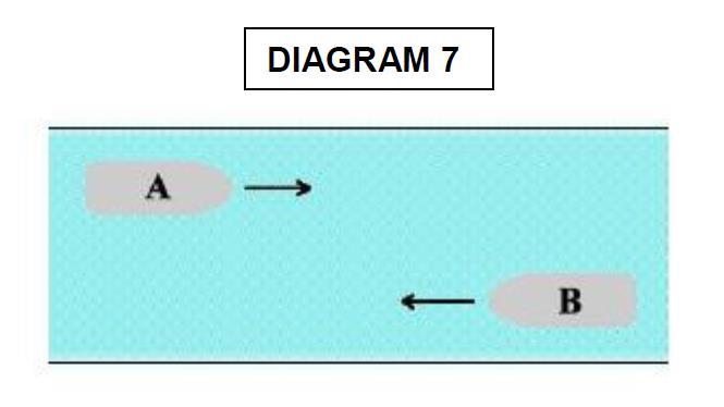
54 DIAGRAM
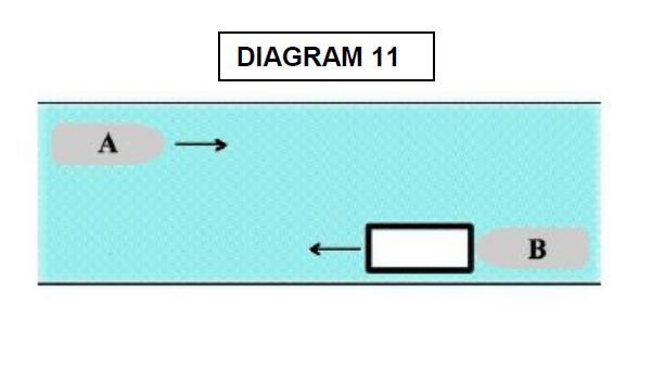
55 1-47
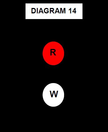
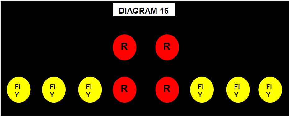
56 1-48
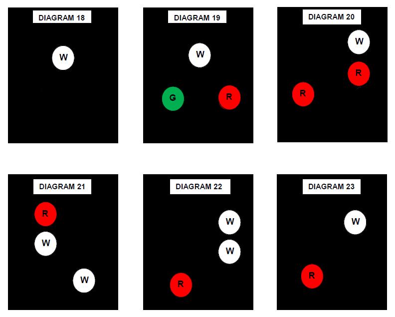
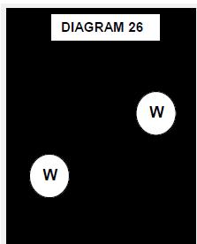

57 1-49
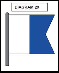
58 1-50

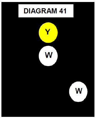
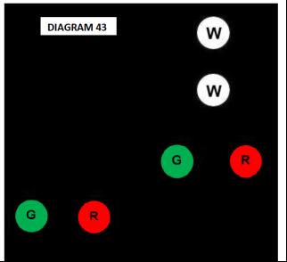
59 DIAGRAM 40 DIAGRAM 41 DIAGRAM

60 DIAGRAM 43 DIAGRAM 44 DIAGRAM
61 NAVIGATION RULES ANSWERS 1. B 13(a) 2. D 34(c) 3. A 35(c) 4. D 34(a) 5. D 23d (ii) 6. C 9(e), 34(c) 7. B 34(a) 8. B D 9(d) 10. B 34(a) 11. D 34(a) 12. B 34(a) 13. A 34(c), 9(e) 14. B 34(a) 15. C 34(c), 9(e) 16. D 34(c)(ii) 17. B 34, 35k 18. D 34(c), 9(e) 19. C 34(d), 9(e) 20. A 34(a) 21. B D A 9(e)(i) 24. D 34(a) 25. D 34(a) 26. C 35(c) 27. B 3(g) 28. D 3g(vi) 29. A 34(c) 30. B 34(c)(d), 9(e) 31. C 9(d) 32. C 34(c) 33. A 30(h), (i) 34. B 9(a)(ii) 35. C 24(f)(i) 36. C 24(c)(iii) Inland 37. A 34(a) 38. D 9(a) 39. C D 34(h) 41. D 34(a) 42. B 18(a)(iv) 43. B 34(h) 44. B 21(a) 45. B 34(c)(i)(2) 46. C 34(a), (g) 47. C 17(a)(i), 34(c) 48. B 34(h) 49. A 34(c) 50. B 34(a) 51. B 34(c) 52. D 9(a)(ii) 53. D 34(c) 54. A 35 (l) 55. C 15, B ANX V C 9(d) 58. A Anx V D 27(d)(iv)(2) 60. A 34(a) 61. C 14(a) 62. A 34(c) 63. A 27(e)(ii) 64. B 30(g) 65. B 24i 66. C 34(g) 67. D 3(k) 68. A 3(q) Inland 69. A 34(a) 70. C 21(d) 71. B 28 INT 72. B 34(a) 73. D 34(a)(i)(2) 74. C 24(c) 75. B 21(b) 76. C 24(c) 77. D 18, 15(b) 78. D 9(d), 15(b) 79. B 34(a) 80. A 34(c) 81. A 33(a) 82. D 3(i) 83. A 34(c) 84. C 34(a) 85. A 13(b) 86. C 27(f) 87. D 27(c) 88. B 17(a)(ii) 89. C 3(j) 90. D 10(b)(i)(ii)(iii) 91. A 3(f) 92. D 19(d)(i) 93. C 13(a) 94. B 15(a) 95. B 18(a) 96. A 24(f)(ii) 97. A 34(a) 98. B 21(b) 99. B 35(g) 100. D 27(d)(ii) 101. A 18(a) 151. B 26(c)(i) 102. C 27(d)(i) 152. B 10(l) 103. A 30(a) 153. A 35(c) 104. D 25(d) 154. C 34(d) 105. A Anx. V C 27(b) 106. D 29(a) 156. C 24(a)(v) 107. A 30(a) 157. C 8(e) 108. B 34(e) 158. C 34(e) 109. D 29(a)(i)(ii) 159. D 24(g) 110. B 1 footnote 160. A 37, Anx IV 111. C D 10(c)(i)(j) 112. A 13, 17(a)(i) 162. B 18(a) 113. B 7(b) 163. A 17(a)(ii) 114. A 21(d) 164. A 17(a) 115. B 26(b) (c) 165. C 35(a) 116. B 23(d)(i)& 23(d) 166. B 25(a) 117. D 37, Anx. IV 167. B 25(c) 118. D 35(g) 168. A 35(e) 119. B 21(a) 169. D 35(c) 120. A 35(g), (h) 170. D 18(b) 121. A 35(c), 3(g) 171. B 34(e) 122. C B 3(g) 123. D 27(e)(ii) 173. C 26(c) 124. B 26(c)(ii) 174. D 26(c) 125. C 21(a) 175. B 27(d)(ii) 126. D 30(b) 176. B 21(d) 127. A 25(e) 177. C 24 (i),(i)(ii) 128. D D 35(c) 129. A 26(c)(ii) 179. D 27(a)(i) 130. D 24(a) 180. B 35(e) 131. A 30(e) 181. C 35(c) 132. C 35(g) 182. C 37, Anx IV 133. D 19(e) 183. C 25(a) 134. B 24(c)(i) 184. A 10(b)(iii) 135. C 21(b) 185. C 32(b) 136. A 21(b) 186. C 23(a) 137. D 24(a)(i) 187. D 3(g)(i), 27(b) 138. C 34(g) 188. B 35(b) 139. B 35(c) 189. D 35(c) 140. A 37, Anx IV(c) 190. A 7(d) 141. D 14(b) 191. A 18(b) 142. C 35(g) 192. B 35(b) 143. C 23(b) 193. A 3(g)(ii) 144. B 24(a) 194. C 27(f) 145. C 18(b) 195. B 24(a)(iv),(e) 146. C 18(a) 196. A 35(h) 147. B 21(b) 197. C 10(c) 148. D 3(g)(v) 198. A 20(b), (c) 149. C 27(a)(ii) 199. D 25(e) 150. B 34(e) 200. C 24(g) 201. B 26(c)(ii) 202. A 30(a)(i) 203. C 30(b) 204. D 23(a) 205. C 29(a) 206. B 26(c)(i) 207. B 27(b)(i)(ii) 208. D 23(a)(i)(iii) 209. B 24(a)(iii)(iv) 210. C 25(c) 211. D 30(a)(i)(ii) 212. C 26(b)(i)(ii)(iii) 213. D 26(b)(i)(ii) 214. B 25(a) 215. D 24(a)(i)(ii) 216. C 26(a), (b)(i) 217. C C 3(j) 219. B 27(b)(i)(iii) 220. D 27(a)(i)(iii) 221. D C 27(b)(ii) 223. B 27(a)(ii) 224. C 27(c) 225. A 30(d)(ii) 226. C 27(b)(ii), 3(g)(i) 227. A 25(a)(i) 228. A 24(f)(ii), (c)(i)(ii) 229. C 24(a)(i)(ii) 230. B 24(a) 231. D A 7(b) 233. A 19(d)(ii) 234. A 8(a) 235. D 21(b) 236. D D D 35(a)(b)(c) 239. B D 21(e) 241. A A D 14(b) 244. A A 26(b)(i), (c)(i) 246. A 32(b) 247. C 32(c) 248. B 21(c) 249. A 21(c) 250. A 26(f), ANEX II RULES OF THE ROAD ANSWER SHEET 1-53
62

63 TRAINING RESOURCES MARITIME INSTITUTE NAVIGATION GENERAL CHAPTER 2 COMMUNICATIONS
64 Introduction The student will be more knowledgeable about communications and associated electronic equipment. The student will also acquire knowledge about the VHF-FM radio and station license requirements. Most importantly the student will learn how to make a distress call, use a DSC equipped radiotelephone and Pro-words. Before you purchase anything else, make sure you have a reliable VHF marine radio. A VHF marine radio is the single most important radio system you should buy. If you plan to travel more than a few miles offshore, plan to purchase an MF/HF radiotelephone or mobile satellite telephone, an emergency position indicating radio beacon, or EPIRB, and a second VHF radio or cellular telephone as well. Mobile satellite telephones are becoming less expensive. The mobile satellite will provide easier and clearer communications than the MF/HF radiotelephone; however, the HF radiotelephone will receive high seas marine weather warnings Objectives The material in this chapter will enable the student to: Have a working knowledge of, Basic communications and associated electronic equipment, Radio waves/wavelength and frequencies, Understand basic license requirements, Know how to make a distress call, Use DSC (Digital Select Calling) equipment, Understand and use, Vessel Bridge to Bridge Radiotelephone Regulations from COMDTINST M d Navigation Rules International-Inland, RADIOTELEPHONE REGULATIONS Radiotelephone requirements from Title 47 Code of Federal Regulations (Telecommunication) PART 80 Stations in the Marine Services, Identify and Describe the GLOBAL MARITIME DISTRESS & SAFETY SYSTEM (GMDSS), Use the phonetic alphabet to spell out words or acronyms that may not transmit clearly. References (a) U. S. Coast Guard Navigational Rules and Regulations Handbook. (b) Title 47 Code of Federal Regulations (Telecommunication) PART 80 Stations in the Marine Services. (c) Title 33 Code of Federal Regulations (Navigation and Navigable Waters) PART 26 Vessel Bridge to Bridge Radiotelephone Regulations. (d) PUB.102, INTERNATIONAL CODE OF SIGNAL, Marine Safety Information Division, National Imagery and Mapping Agency (NIMA). (e) United States Coast Pilot. (f) COMDTINST M2300.7A RADIOTELEPHONE HANDBOOK. (g) ecfr.gpoaccess.gov (Code of Regulations website). 2-2
65 Topics Topic Page Introduction 2-2 Objectives 2-2 References 2-2 Topics 2-3 Radio Waves/Wavelength 2-5 Radio Frequencies 2-5 Line of Sight Transmission 2-6 Line of Sight Diagram 2-6 Radio Equipment 2-6 HF/MF (SSB) Marine Radio 2-6 VHF Marine Radio 2-7 EPRIB (Emergency Position Indicating Radiobeacons) 2-7 Vessel Bridge to Bridge Radiotelephone Regulations 2-7 Radiotelephone Required 2-8 Use of the Designated Frequency 2-8 Use of the Radiotelephone 2-8 Maintenance of Radiotelephone 2-9 Failure of Radiotelephone 2-9 Communications 2-9 Authority of the Master 2-9 Radiotelephone Operating Procedures for Ship Stations 2-9 Watch Requirement by the Bridge to Bridge Act 2-10 Bridge to Bridge Communication Procedures 2-10 Morse Code & Phonetic Pronunciation 2-12 Common Procedure Words (Prowords) 2-13 Available Marine Channels and Their Uses 2-15 Required Frequencies for Radiotelephony 2-15 License Requirements 2-16 Station License Requirements 2-16 Operator Requirements Classification of Operator License and Endorsement 2-16 Operating Requirements and Procedures, Order of Priority of Communications 2-16 Control of Distress Traffic (MAYDAY) 2-17 Urgency Signals and Messages (PAN PAN) 2-17 Safety Signals and Messages (SECURITE) 2-17 Digital Select Calling (DSC) 2-17 Maritime Mobile Service Identity (MMSI Numbers) 2-17 Global Maritime Distress & Safety System (GMDSS) 2-18 GMDSS Diagram 2-18 National Distress and Response (RESCUE 21) 2-19 RESCUE 21 Diagram 2-19 Safety Watch Requirements and Procedures, Authority for Distress Transmissions (MAYDAY) 2-20 Radiotelephone Distress Call and Message Transmission Procedures 2-20 Radiotelegraph and Radiotelephone Alarm Signals 2-20 Regulations Requiring Monitoring and Listening to VHF Marine Radios
66 Topic Page Station Documents, Station Logs 2-21 Ship Radiotelephone Logs 2-21 Who Regulates Whom? 2-22 Communication Questions 2-23 Communication Answers

67 Radio Waves/Wavelength Radio waves are described by the frequency with which these waves occur per second: in other words, by the number of waves per second. The technical term used is a Hertz, named after Dr. Heinrich Hertz, a 19th Century German physicist. 1 hertz (1Hz) means one wave per second, 1 kilohertz (1 khz) means 1,000 waves per second and 1 megahertz (1MHz) means 1,000,000 waves per second. Three different frequency bands are reserved solely for marine communications. They are: MF (medium frequency) from 1.6 to 4.2 MHz. HF (high frequency) from 4 to 25 MHz used for over-the-horizon communications. VHF from 156 to 174 MHz used for line-of-sight communications khz Very low frequency VLF khz Low frequency LF 300 khz - 3 MHz Medium frequency MF 3-30 MHz High frequency HF MHz Very high frequency VHF 300 MHz - 3 GHz Ultra high frequency UHF 3-30 GHz Super high frequency SHF GHz Extra high frequency EHF 2-5


68 Line - Of - Sight Transmission Line-of-sight is the direct propagation of radio waves between antennas that are visible to each other. This is probably the most common of the radio propagation modes at VHF and higher frequencies. Because radio signals can travel through many non-metallic objects, radio can be picked up through walls. This is still line-of-sight propagation. Examples would include propagation between a satellite and a ground antenna or reception of television signals from a local TV transmitter. Skywave propagation, also referred to as skip, is any of the modes that rely on refraction of radio waves in the ionosphere, which is made up of one or more ionized layers in the upper atmosphere. Radio Equipment Before you purchase anything else, make sure you have a reliable VHF marine radio. A VHF marine radio is the single most important radio system you should buy. If you plan to travel more than a few miles offshore, plan to purchase an MF/HF radiotelephone or mobile satellite telephone, an emergency position indicating radio beacon, or EPIRB, and a second VHF radio or cellular telephone as well. Mobile satellite telephones are becoming less expensive. The mobile satellite will provide easier and clearer communications than the MF/HF radiotelephone; however, the HF radiotelephone will receive high seas marine weather warnings. HF/MF (SSB) Marine Radio HF/SSB radio plays an important part in maritime communications; it provides mariners with a viable and effective form of communication over long distances. Not only is it an efficient form of communication, HF/SSB radio offers other benefits as well including , weather reports and charts, shortwave broadcast, etc. 2-6
 capability.")


69 VHF Marine Radio Modern day marine VHF radios not only offer basic transmit and receive capabilities, many package additional features that truly make these radios indispensable for the mariner. For the last several years, all fixed mount marine VHF radios have required by certification, some level of "Digital Selective Calling" (DSC) capability. Even the basic set has the ability to alert other boats, ships and shore stations with a single button press. More expensive radios offer far more extensive DSC capabilities. These may include position polling or a variety of group calling options. Most mid-priced marine VHF radios integrate other features too. Many have the ability to connect to a remote microphone and act as an intership intercom system. Still others have a built-in hailer that, when connected to an external hailer horn, can act as a public address system and/or output required fog signals when conditions warrant. The most sophisticated marine VHF radios have an alphanumeric keypad for data entry, are able to connect to optional voice scramblers, and a few even have the ability to use a Bluetooth headset. The newest combination of features offered is the integration of a complete Class B AIS unit with a marine VHF radio. Marine VHF mostly uses "half-duplex" transmission, where communication can only take place in one direction at a time. A transmit button on the set or microphone determines whether it is operating as a transmitter or a receiver. EPIRB (Emergency Position Indicating Radiobeacons) EPIRBs (pronounced ee-pirbs), formally Emergency Position Indicating Radiobeacons, are devices that transmit a digital signal on the international distress signal frequency 406 MHz, Designed to work with satellites, EPIRBs are detectable by COSPAS-SARSAT satellites, which orbit the poles, and by the GEOSAR system, which consists of GOES weather satellites and other geostationary satellites. Vessel Bridge to Bridge Radiotelephone Regulations Ref. (a) Page 162 Title 33 PART Purpose (a) The purpose of this part is to implement the provisions of the Vessel Bridge-to-Bridge Radiotelephone Act. This part: (1) Requires the use of the vessel bridge-to-bridge radiotelephone; (2) Provides the Coast Guard's interpretation of the meaning of important terms in the Act; (3) Prescribes the procedures for applying for an exemption from the Act, the regulations issued under the Act and a listing of exemptions. (b) Nothing in this part relieves any person from the obligation of complying with the Rules of the Road and the applicable pilot rules. 2-7
70 26.03 Radiotelephone required. (a) Unless an exemption is granted under and except as provided in paragraph (a)(4) of this section, this part applies to: (1) Every power-driven vessel of 20 meters or over in length while navigating; (2) Every vessel of 100 gross tons and upward carrying one or more passengers for hire while navigating; (3) Every towing vessel of 26 feet or over in length while navigating; and (4) Every dredge and floating plant engaged in or near a channel or fairway, in operations likely to restrict or affect navigation of other vessels except for an unmanned or intermittently manned floating plant under the control of a dredge. (b) Every vessel, dredge, or floating plant described in paragraph (a) of this section, must have a radiotelephone on board capable of operation from its navigational bridge; or in the case of a dredge, from its main control station, and capable of transmitting and receiving on the frequency or frequencies within the Mega-Hertz band using the classes of emissions designated by the Federal Communications Commission for the exchange of navigational information Use of the designated frequency. (a) No person may use the frequency designated by the Federal Communications Commission under section 8 of the Act, 33 U.S.C. 1207(a), to transmit any information other than information necessary for the safe navigation of vessels or necessary tests. (b) Each person who is required to maintain a listening watch under Section 5 of the Act shall, when necessary, transmit and confirm, on the designated frequency, the intentions of his vessel and any other information necessary for the safe navigation of vessels. (c) Nothing in these regulations may be construed as prohibiting the use of the designated frequency to communicate with shore stations to obtain or furnish information necessary for the safe navigation of vessels. (d) On the navigable waters of the United States, Channel 13 ( MHz) is the designated frequency required to be monitored in accordance with 26.05(a) except that in the area prescribed in 26.03(e), Channel 67 ( MHz) is the designated frequency. (e) On those navigable waters of the United States within a VTS area, the designated VTS frequency is an additional designated frequency required to be monitored in accordance with Channel 13 ( MHz) Navigational (Ship to Ship), also used at locks and bridges Use of radiotelephone. Section 5 of the Act states that the radiotelephone required by this Act is for the exclusive use of the master or person in charge of the vessel, or the person designated by the master or person in charge to pilot or direct the movement of the vessel, who shall maintain a listening watch on the designated frequency. Nothing herein shall be interpreted as precluding the use of portable radiotelephone equipment to satisfy the requirements of this act. 2-8
71 26.06 Maintenance of Radiotelephone; Failure of Radiotelephone. Section 6 of the Act states: (a) Whenever radiotelephone capability is required by this Act, a vessel's radiotelephone equipment shall be maintained in effective operating condition. If the radiotelephone equipment carried aboard a vessel ceases to operate, the master shall exercise due diligence to restore it or cause it to be restored to effective operating condition at the earliest practicable time. The failure of a vessel's radiotelephone equipment shall not, in itself, constitute a violation of this Act, nor shall it obligate the master of any vessel to moor or anchor his vessel; however, the loss of radiotelephone capability shall be given consideration in the navigation of the vessel. The failure of the vessel s radiotelephone equipment shall not, in itself, constitute a violation of the Act, nor shall it obligate the master of any vessel to moor or anchor his vessel, however; the loss of radiotelephone capability shall be given consideration in the navigation of the vessel Communications. No person may use the services of, and no person may serve as, a person required to maintain a listening watch under section 5 of the Act, 33 U.S.C. 1204, unless the person can communicate in the English language. Title 47 Code of Federal Regulations (Telecommunication) PART 80-Stations in the Marine Services Title 47 SUBPART C Authority of the Master. (a) The service of each ship station must at all times be under the ultimate control of the master, who must require that each operator or such station comply with the Radio Regulations in force and that the ship station is used in accordance with those regulations. (b) These rules are waived when the vessel is under the control of the U.S. Government. Title 47 SUBPART C Radiotelephone Operating Procedures for Ship Stations. (a) Calling coast stations. (1) Use by ship stations of the frequency 2182 khz for calling coast stations and for replying to calls from coast stations is authorized. However, such calls and replies should be on the appropriate ship-shore working frequency. (2) Use by ship stations and marine utility stations of the frequency MHz for calling coast stations and marine utility stations on shore, and for replying to calls from such stations, is authorized. However, such calls and replies should be made on the appropriate ship-shore working frequency. (b) Calling ship stations. (1) Except when other operating procedure is used to expedite safety communication, ship stations, before transmitting on the intership working frequencies 2003, 2142, 2638, 2738, or 2830 khz, must first establish communications with other ship stations by call and reply on 2182 khz. Calls may be initiated on an intership working frequency when it is known that the called vessel maintains a simultaneous watch on the working frequency and on 2182 khz. 2-9
72 (2) Except when other operating procedures are used to expedite safety communications, the frequency MHz must be used for call and reply by ship stations and marine utility stations before establishing communication on one of the intership working frequencies. Calls may be initiated on an intership working frequency when it is known that the called vessel maintains a simultaneous watch on the working frequency and on MHz. (c) Change to working frequency. After establishing communication with another station by call and reply on 2182 khz or MHz stations on board ship must change to an authorized working frequency for the transmission of messages. (d) Limitations on calling. Calling a particular station must not continue for more than 30 seconds in each instance. If the called station does not reply, the station must not again be called until after an interval of 2 minutes. When a called station does not reply to a call sent three times at intervals of 2 minutes, the calling must cease and must not be renewed until after an interval of 15 minutes; however, if there is no reason to believe that harmful interference will be caused to other communications in progress, the call sent three times at intervals of 2 minutes may be repeated after a pause of not less than 3 minutes. In event of an emergency involving safety, the provisions of this paragraph do not apply. (e) Limitations on working. Any one exchange of communications between any two ship stations on 2003, 2142, 2638, 2738, or 2830 khz or between a ship station and a private coast station on 2738 or 2830 khz, must not exceed 3 minutes after the stations have established contact. Subsequent to such exchange of communications, the same two stations must not again use 2003, 2142, 2638, 2738, or 2830 khz for communication with each other until 10 minutes have elapsed. (f) Transmission limitation on 2182 khz and MHz are to facilitate the reception of distress calls. All transmissions on 2182 khz and MHz (channel 16) must be minimized and transmissions on MHz must not exceed 1 minute. (g) Limitations on commercial communication. On frequencies in the band MHz, the exchange of commercial communication must be limited to the minimum practicable transmission time. In the conduct of ship-shore communication other than distress, stations on board ship must comply with instructions given by the private coast station or marine utility station on shore with which they are communicating. Title 47 SUBPART G Watch required by the Bridge-to-Bridge Act In addition to the watch requirement contained in , all vessels subject to the Bridge-to-Bridge Act must keep a watch on the designated navigational frequency. The watch must be maintained by the master or person in charge of the vessel or the person designated by the master or person in charge to pilot or direct the movement of the vessel. The person standing watch may perform other duties provided such other duties do not interfere with the watch. Subpart G Safety Watch Requirements and Procedures Distress, Alarm, Urgency and Safety Procedure Title 47 SUBPART G Bridge-to-Bridge Communication Procedure (a) (1) This is the (name of vessel). My position is (give readily identifiable position, course and speed) about to (describe contemplated action). Out. (2) Vessel off (give a readily identifiable position). This is (name of vessel) off (give a readily identifiable position). I plan to (give proposed course of action). Over. (3) (Coast station), this is (vessel's name) off (give readily identifiable position). I plan to (give proposed course of action). Over. 2-10
73 (b) Vessels acknowledging receipt must answer, (Name of vessel calling). This is (Name of vessel answering). Received your call, and follow with an indication of their intentions. Communications must terminate when each ship is satisfied that the other no longer poses a threat to its safety and is ended with Out. This is the (fishing vessel RHUMB PUNCH). My position is ( ' N, ' W, on course 085 T, speed 7 knots) about to (alter course to port and steady on new course 075 ). Out. Vessel off (green buoy #21). This is (RHUMB PUNCH) off (your starboard bow). I plan to (alter course to port). Over. (c) Use of power greater than 1 watt in a bridge-to-bridge station shall be limited to the following three situations: (1) Emergency. (2) Failure of the vessel being called to respond to a second call at low power. (3) A broadcast call as in paragraph (a)(1) of this section in a blind situation, e.g., rounding a bend in a river. Use the Phonetic Alphabet to spell out words or acronyms that may not transmit clearly. Call signs and coordinates should be spelled out phonetically Spelling out may be necessary to communicate obscure or unpronounceable words or abbreviations. They may be spelled out after the proword, I SPELL. If the word is pronounceable, say it before and after spelling it out. In difficult conditions, it may be more effective to use full words than to risk having to spell out an abbreviation. One method of reducing the length of radio transmissions without distorting the meaning of your words is by using procedure words (prowords). 2-11
74 EXCERPTS FROM PUB 102 CHARACTER MORSE TELEPHONY PHONIC CODE (PRONUNCIATION) A Alfa AL-FAH B Bravo BRAH-VOH C Charlie CHAR-LEE or SHAR-LEE D Delta DELL-TAH E Echo ECK-OH F Foxtrot FOKS-TROT G Golf GOLF H Hotel HOH-TELL I India IN-DEE-AH J Juliett JEW-LEE-ETT K Kilo KEY-LOH L Lima LEE-MAH M Mike MIKE N November NO-VEM-BER O Oscar OSS-CAH P Papa PAH-PAH Q Quebec KEH-BECK R Romeo ROW-ME-OH S Sierra SEE-AIR-RAH T Tango TANG-GO U Uniform YOU-NEE-FORM OR OO-NEE-FORM V Victor VIK-TAH W Whiskey WISS-KEY X X-ray ECKS-RAY Y Yankee YANG-KEY Z Zulu ZOO-LOO 2-12
75 EXCERPTS FROM COMDTINST M2300.7A RADIOTELEPHONE HANDBOOK Common Procedure Words (Prowords) Proword ACKNOWLEDGE Meaning Confirm that you have received my message and will comply. AFFIRMATIVE NEGATIVE Yes/Correct No/Incorrect ALL AFTER ALL BEFORE Everything that you (I) transmitted after. Everything that you (I) transmitted before. BREAK BREAK BREAK! All stations will immediately cease transmission. The station breaking in has an urgent message. (Used only in extreme emergency) CORRECT CORRECTION WRONG You are correct. The correct version is. Your last transmission was incorrect; the correct version is. DIREGARD THIS TRANSMISSION- OUT This transmission is an error; disregard it. OUT DO NOT ANSWER, no transmission necessary FIGURES Numbers follow (in the message). MESSAGE FOLLOWS I have an informal message for you. I have a formal message which should be recorded (e.g. written down). OVER This is the end of my transmission to you and a response is necessary. Go ahead and transmit. (Note: Observe the considerable difference between Over used during a message exchange, and Out employed at the end of an exchange. Over should be omitted when the context of a transmission makes it clear that it is unnecessary.) An operator should NEVER end a transmission with Over and Out as the meanings are contradictory. 2-13
76 Proword ROGER I SPELL WAIT Meaning I have received your last transmission. I shall spell the next word phonetically. Often used where a proper name or unusual word is important to a message or when communications are poor. For example Boat name is Martha. I spell Mike; Alfa; Romeo; Tango; Hotel; Alfa. (See phonetic alphabet.) I must pause a few seconds; stand by for further transmission. (Used when a message must be interrupted by the sender. If, for instance, one station is asked for information not instantly available, its operator would send WAIT while looking up the required data) THIS IS This transmission is from the station whose name or call sign immediately follows. (Note: Normally used at the beginning of a transmission) BLUE DUCK THIS IS GIMLET WZE (Sometimes omitted in transmissions between experienced operators familiar with each other s boat names.) NEGATIVE No 2-14
77 AVAILABLE MARINE CHANNELS AND THEIR USES DESIGNATED BY THE FEDERAL COMMUNICATION COMMISION Channel Transmit Receive Intended Use INTERSHIP SAFETY. Required for all VHF-FM equipped vessels. For intership safety purposes and search and rescue (SAR), communications with ships and aircraft of the U.S. Coast Guard must not be used for non-safety communications COMMERCIAL AND NON-COMMERICAL (INTERSHIP AND SHIP-TO-COAST). Some examples of use are; communications with commercial marinas and public docks to obtain supplies or schedule repairs, and contacting commercial vessels about matters of common concern. Also available in U.S. waters as an alternate calling channel for non-commercial vessels NAVIGATIONAL (SHIP S) BRIDGE TO (SHIP S) BRIDGE. This channel is available to all vessels and is required on large passenger and commercial vessels (including many tugs). Use is limited to navigational communications such as in meeting and passing situations. Abbreviated operation procedures (call signs omitted) and 1 watt power (except in certain special instances) are used on this channel for both calling and working. For recreational vessels, this channel should be used for listening to determine the intentions of large vessels. This is also the primary channel used at locks and bridges DISTRESS, SAFETY AND CALLING (INTERSHIP AND SHIP-TO- COAST), ALSO EPIRB s. Required channel for all VHF-FM equipped vessels. Must be monitored at all times station is in operation (except when actually communicating on another channel). This channel is also monitored by the Coast Guard, public coast stations, and many limited coast stations. Calls to other vessels are normally initiated on this channel, then, except in an emergency, you must switch to a working channel. 22A COAST GUARD LIAISON AND MARITIME SAFETY INFORMATION BROADCASTS. This channel is used for communications with U. S. Coast Guard ship, coast and aircraft stations. Navigational warnings and, where not available on Weather (WX) channels, Marine Weather forecasts are made on this frequency. Further channels are listed in the GENERAL INFORMATION chapter of the Coast Pilot and in the Marine Radio Users Handbook. All channels given, are designated for both ship-to-ship and ship-to-coast communications. Title 47 SUBPART C Required Frequencies for Radiotelephony. (b) Except as provided in paragraph (c) of this section, at least one VHF radiotelephone transmitter/receiver must be able to transmit and receive on the following frequencies: (1) The distress, safety and calling frequency MHz (Ch-16); (2) The primary intership safety frequency MHz (Ch-06); (3) One or more working frequencies; and (4) All other frequencies necessary for its service. 2-15
78 (c) Where a ship ordinarily has no requirement for VHF communications, handheld VHF equipment may be used solely to comply with the bridge-to-bridge navigational communication requirements contained in subpart U of this part. License Requirements Title 47 SUBPART B Station License Required. (c) A ship station is licensed by rule and does not need an individual license issued by the FCC if the ship station is not subject to the radio equipment carriage requirements of any statute, treaty or agreement to which the United States is signatory; the ship station does not travel to foreign ports and the ship station does not make international communications. A ship station licensed by rule is authorized to transmit radio signals using a marine radio operating in the MHz band; any type of AIS, any type of EPIRB and any type of radar installation. All other transmissions must be authorized under a ship station license. Even though an individual license is not required, a ship station licensed by rule must be operated in accordance with all applicable operating requirements, procedures and technical specifications found in this part. Title 47 SUBPART D Operator Requirements, Classification of Operator Licenses and Endorsements. (a) Commercial radio operator licenses issued by the Commission are classified in accordance with the Radio Regulations of the International Telecommunication Union. (b) The following licenses are issued by the Commission. International classification, if different from the license name, is given in parentheses. The licenses and their alphanumeric designator are listed in descending order. (5) MP. Marine Radio Operator Permit (radiotelephone operator's restricted certificate). Required in Mexican waters Title 47 SUBPART C Operating Requirements and Procedures, Order of Priority of Communications. (a) All stations in the maritime mobile service and the maritime mobile-satellite service shall be capable of offering four levels of priority in the following order: (1) Distress calls, distress messages, and distress traffic = MAYDAY (2) Urgency communications = (3) Safety communications = PAN-PAN SECURITE (4) Other communications. (b) In a fully automated system, where it is impracticable to offer all four levels of priority, Category 1 shall receive priority until such time as intergovernmental agreements remove exemptions granted for such systems from offering the complete order of priority. 2-16
79 Control of Distress Traffic. MAYDAY (a) Distress traffic consists of all messages relating to the immediate assistance required by the mobile station in distress. In distress traffic, the distress signal must be sent before the call and at the beginning of the preamble of any radiotelegram Urgency Signals and Messages. PAN-PAN (a) The urgency signal indicates that the calling station has a very urgent message to transmit concerning the safety of a ship, aircraft, or other vehicle, or the safety of a person. The urgency signal must be sent only on the authority of the master or person responsible for the mobile station Safety Signals and Messages. SECURITE (a) The safety signal indicates that the station is about to transmit a message concerning the safety of navigation (buoy off station, vessel movements) or giving important meteorological warnings. Digital Selective Calling (DSC) If you look at most new marine radios, you will notice a red button marked DISTRESS protected by a spring-loaded cover to prevent it from being accidentally pressed. This button tells you that the radio has DSC, (Digital Selective Calling). DSC is an advanced, computerized form of VHF and MF radio designed for marine use. Digital Selective Calling (DSC) radio technology provides boaters with unique features which will be discussed. To be fully functional, three items must be available: A DSC radio, A Maritime Mobile Service Identity (MMSI) number, A Compatible GPS. DSC technology makes a VHF radio function more like a telephone. It allows boaters to send a digital call directly to another DSC equipped vessel or shore station. In an emergency, one push of a button and the DSC radio will send an automated digital distress alert consisting of your identification (MMSI), and position (if the radio is connected to a GPS) to other DSC equipped vessels and rescue facilities. You can privately hail another DSC equipped vessel, or shore station, if you know their MMSI. It is similar to having a VHF phone number which rings the radio called and then automatically switches you to a pre-determined working channel (channel 70). VHF-DSC has the same range as ordinary VHF as well as the same power restrictions, but it is more efficient than ordinary VHF. Maritime Mobile Service Identity (MMSI Numbers) The MMSI number is nine digits long. The first three digits are the country identifier, followed by another six digits which are unique to your marine radio. United States country identifiers are 303, 338, 366, 367, 368 or 369. MMSI numbers are issued free of charge. You can apply for one by filling out Form 605 which is available online at the FCC web site: You can also apply directly with Boat US and SeaTow. 2-17

 and basic communication links.")
80 DSC radios can usually store MMSI numbers in much the same way that a cellular phone does. Some allow you to show boat names, etc. and these names appear on the DSC radio's screen when receiving a call from a station whose MMSI number is stored in your radio's memory. Global Maritime Distress & Safety System (GMDSS) The is an GMDSS automated ship-to-ship, shore-to-ship and ship-to-shore system covering distress alerting and relay, the provision of maritime safety information (MSI) and basic communication links. Satellite and advanced terrestrial systems are incorporated into a modern communications network to promote and improve safety of life and property at sea throughout the world. The greatest benefit of the GMDSS is that it vastly reduces the chances of ships sinking without a trace and enables search and rescue (SAR) operations to be launched without delay. The system is intended to perform the following functions: alerting (including position determination of the unit in distress), search and rescue coordination, locating (homing), maritime safety information broadcasts, general communications, bridge-to-bridge communications. Specific radio carriage requirements depend upon the ship's area of operation rather than its tonnage. The system also provides redundant means of distress alerting and emergency sources of power. Recreational vessels do not need to comply with GMDSS radio carriage requirements, but will increasingly use the Digital Selective Calling (DSC) VHF radios. Offshore vessels may elect to equip themselves further. Vessels under 300 Gross Tonnage (GT) is not subject to GMDSS requirements. GMDSS Carriage Requirements 2-18
 number.")

81 National Distress and Response (RESCUE 21) Among the biggest advantages, is its compatibility with Digital Selective Calling (DSC), which transmits a vessel s name, location and nature of distress in conjunction with a GPS and Maritime Mobile Service Identity (MMSI) number. Rescue 21 also gives the Coast Guard radio direction-finding capability for non-dsc-enabled vessels. Rescue 21 is the United States Coast Guard s advanced command, control and communications system. Rescue 21 was created to improve the ability to assist mariners in distress, save lives and property at sea. National Distress and Response (RESCUE 21) 2-19
82 Title 47 SUBPART G Safety Watch Requirements and Procedures, Authority for Distress Transmission. A mobile station in distress may use any means at its disposal to attract attention, make known its position and obtain help. A distress call and message, however, must be transmitted only on the authority of the master or person responsible for the mobile station. No person shall knowingly transmit, or cause to be transmitted, any false or fraudulent signal of distress or related communication. Title 47 SUBPART G Radiotelephone Distress Call and Message Transmission Procedure. (a) The radiotelephone distress procedure consists of: (1) The radiotelephone alarm signal (whenever possible), (2) The distress call, (3) The distress message. (b) The DSC distress procedure consists of: (1) Transmission by a mobile unit in distress; (2) Reception; (3) Acknowledgement of distress calls; (4) Distress relays. (c) Radiotelephone distress transmissions must be made slowly and distinctly, each word being clearly pronounced to facilitate transcription. (d) After the transmission by radiotelephony of its distress message, the mobile station may be requested to transmit suitable signals followed by its call sign or name, to permit direction-finding stations to determine its position. This request may be repeated at frequent intervals if necessary. (e) The distress message, preceded by the distress call, must be repeated at intervals until an answer is received. This repetition must be preceded by the radiotelephone alarm signal whenever possible. (f) When the mobile station in distress receives no answer to a distress message transmitted on the distress frequency, the message may be repeated on any other available frequency on which attention might be attracted. Title 14 SUBPART G Radiotelegraph and Radiotelephone Alarm Signals. (b) The international radiotelephone alarm signal consists of two substantially sinusoidal audio frequency tones transmitted alternately. One tone must have a frequency of 2200 Hertz and the other a frequency of 1300 Hertz, the duration of each tone being 250 milliseconds. When generated by automatic means, the radiotelephone alarm signal must be transmitted continuously for a period of at least 30 seconds, but not exceeding one minute; when generated by other means, the signal must be transmitted as continuously as practicable over a period of approximately one minute. The purpose of this special signal is to attract the attention of the person on watch or to actuate automatic devices giving the alarm. 2-20
 whenever the radiotelephone is not being used to communicate (47 CFR 80.309 & 310). Title 47 SUBPART I 80.409 Station Documents, Station Logs.")
83 Regulations Requiring Monitoring and Listening to VHF Marine Radios In general, any vessel equipped with a VHF marine radiotelephone (whether voluntarily or required to) must maintain a watch on channel 16 ( MHz) whenever the radiotelephone is not being used to communicate (47 CFR & 310). Title 47 SUBPART I Station Documents, Station Logs. Radiotelephony stations subject to the Communications Act, the Safety Convention or the Bridge-to- Bridge Act, must record entries indicated by paragraphs (e)(1) through (e)(12) of this section. Additionally, the radiotelephone log must provide an easily identifiable, separate section relating to the required inspection of the ship's radio station. (a) General requirements. Logs must be established and properly maintained as follows: (1) The log must be kept in an orderly manner. The log may be kept electronically or in writing. The required information for the particular class or category of station must be readily available. Key letters or abbreviations may be used if their proper meaning or explanation is contained elsewhere in the same log. (2) Erasures, obliterations, or willful destruction of written logs, or deletions of data or willful destruction of computer files or computer hardware containing electronic logs, is prohibited during the retention period. Corrections may be made only by the person originating the entry by striking out the error, initialing the correction and indicating the date of correction. With respect to electronic logs, striking out the error is to be accomplished using a strike-through formatting effect or a similar software function, and the correction is to be acknowledged through a dated electronic signature at the location of the strike-through. (b) Availability and retention. Station logs must be made available to authorized Commission employees upon request and retained as follows: (1) Logs must be retained by the licensee for a period of two years from the date of entry, and, when applicable, for such additional periods as required by the following paragraphs: (i) Logs relating to a distress situation or disaster must be retained for three years from the date of entry. (e) Ship Radiotelephone Logs. Logs of ship stations which are compulsorily equipped for radiotelephony, must contain the following applicable log entries and the time of their occurrence: (1) A summary of all distress and urgency communications affecting the station's own ship, all distress alerts relayed by the station's own ship and all distress call acknowledgements and other communications received from search and rescue authorities. (2) A summary of safety communications on other than VHF channels affecting the station's own ship. (3) An entry that pre-departure equipment checks were satisfactory and that required publications are on hand. Daily entries of satisfactory tests to ensure the continued proper functioning of GMDSS equipment shall be made. 2-21
84 (4) An entry describing any malfunctioning GMDSS equipment and another entry when the equipment is restored to normal operation. (5) A weekly entry that: (i) The proper functioning of digital selective calling (DSC) equipment has been verified by actual communications or a test call; (ii) The portable survival craft radio gear and radar transponders have been tested; and (iii) The EPIRBs have been inspected. (6) An entry at least once every thirty days that the batteries or other reserve power sources have been checked and are functioning properly. (7) The time of any inadvertent transmissions of distress, urgency and safety signals including the time and method of cancellation. (8) At the beginning of each watch, the Officer of the Navigational Watch, or GMDSS Operator on watch, if one is provided, shall ensure that the navigation receiver is functioning properly and is interconnected to all GMDSS alerting devices which do not have integral navigation receivers, including: VHF DSC, MF DSC, satellite EPIRB and HF DSC or INMARSAT SES. On a ship without integral or directly connected navigation receiver input to GMDSS equipment, the Officer of the Navigational Watch, or GMDSS Operator on watch, shall update the embedded position in the GMDSS equipment. An appropriate log entry of these actions shall be made. (9) A GMDSS radio log entry shall be made whenever GMDSS equipment is exchanged or replaced (ensuring that ship MMSI identifiers are properly updated in the replacement equipment), when major repairs to GMDSS equipment are accomplished and when annual GMDSS inspections are conducted. (10) Results of required equipment tests, including specific gravity of lead-acid storage batteries and voltage reading of other types of batteries provided as a part of the compulsory installation. (11) Results of inspections and tests of compulsorily fitted lifeboat radio equipment. (12) A daily statement about the condition of the required radiotelephone equipment, as determined by either normal communication or test communication. (13) When the master is notified about improperly operating radiotelephone equipment. Who Regulates Whom? Three U.S. government agencies, the Federal Communications Commission, the National Telecommunications and Information Administration, and the U.S. Coast Guard; and two international organizations, the International Telecommunications Union and the International Maritime Organization; have each established marine radio watch keeping regulations. Regulations on radio watch keeping exist for all boats and ships commercial, recreational, government and military, domestic and foreign carrying marine radios. 2-22
85 COMMUNICATIONS QUESTIONS 1. What is the correct phonetic pronunciation of the letter Z? A. ZEB-BR-AH B. ZEE-ZEE C. ZEE-HEE D. ZOO-LOO 6. The Coast Guard broadcasts routine weather reports on channel(s)? A. 13 or 14 B. 16 and 17 C. 22A D. 44 or What does the pro-word OVER mean? A. pause momentarily until information is gathered B. disregard my last transmission C. end of transmission, no response is necessary D. end of transmission, response is necessary 7. The radiotelephone required by the Vessel Bridge-to-Bridge Radiotelephone Act, is for the exclusive use of. A. the master or person in charge of the vessel B. a person designated by the master C. a person onboard to pilot the vessel D. any of the above 3. The distress, safety and calling frequency is channel. A. 13 B. 16 C. 18 D You are required to maintain a continuous listening watch on channel. A. 6 (156.3 MHz) B. 12 (156.6 MHz) C. 14 (156.7 MHz) D. 16 (156.8 MHz) 4. The regulations governing the frequencies of the bridge-to-bridge radiotelephone are promulgated by the. A. Department of Transportation B. Federal Communications Commission C. U.S. Coast Guard D. Department of Defense 5. To facilitate the reception of distress traffic, all transmissions on (CH-16) must not exceed. A. 30 seconds B. 1 minute C. 2 minutes D. 15 minutes 9. The radio message urgently concerned with safety of a person overboard would be prefixed by the word/s. A. Mayday B. Pan Pan C. Safety D. Securite 10. The Bridge-to-Bridge VHF radiotelephone frequency is? A. channel 16 B. channel 14 C. channel 13 D. channel
86 11. What is the normal operating power for ship-to-ship communications on channel 13? A. 1 watt or less B. 5 watts C. 10 watts D. 25 watts 12. Every vessel navigated in violation of the Vessel Bridge-to-Bridge Radiotelephone Act or the regulations thereunder, is subject to a penalty of not more than. A. $100 B. $500 C. $1000 D. $ If your bridge-to-bridge radiotelephone ceases to operate, you must. A. immediately anchor your vessel and arrange for repairs to the system B. moor your vessel at the nearest dock available and arrange for repairs to the system C. arrange for the repair of the system so that repairs are completed within 48 hours D. exercise due diligence to restore the system at the earliest practicable time 14. If your bridge-to-bridge radiotelephone fails while underway. A. visual signals must be given to oncoming vessels B. you must immediately tie up in the nearest port until the radiotelephone is repaired C. you must anchor until the radiotelephone is repaired D. the loss of the radiotelephone must be considered in navigating the vessel 15. What should you do if you have transmitted a distress call a number of times on channel 16 and have received no reply? A. repeat the message using any other channel on which you might attract attention B. key the microphone several times before transmitting again C. turn up the volume on the receiver before transmitting again D. report the problem to the head electrician 16. If you know that the vessel you are about to call on the VHF radio maintains a radio watch on both the working and the calling frequencies, which frequency should you use? A. calling frequency B. distress frequency C. urgency frequency D. working frequency 17. Which radiotelephone transmission may be sent over channel 16? A. distress signal MAYDAY B. call to a particular station C. a meteorological warning D. all of the above 18. A Coast Guard radiotelephone message about an aid to navigation that is off station is preceded by the word. A. "PAN-PAN" B. "MAYDAY" C. "SOS" D. "SECURITE" 19. One method of reducing the length of radio transmissions without distorting the meaning of your words is by using. A. slang B. secret codes C. procedure words D. analog 2-24
87 20. You have just tried calling another vessel on the VHF and they have not replied. How long should you wait before calling that station again? A. two minutes B. one minute C. three minutes D. five minutes 21. What is the correct phonetic pronunciation of the letter O? A. OS-CAR B. OSS-CAH C. OZZ-KER D. OSS-KOR 23. What is the expected range of VHF channel 16? A. 15 to 20 miles B. unlimited range C. 10 miles D. 120 to 150 miles 24. A message warning of a tropical storm should be sent as a/an? A. routine message B. urgent message C. distress message D. safety message 22. Normally, if a station does not reply after being called 3 times, you may not call that station for. A. 2 minutes B. 3 minutes C. 15 minutes D. 30 minutes 2-25
88 COMMUNICATIONS ANSWERS 1. D pg. 12, Pub 102 Chpt. 1 Sec D pg B pg. 14, 47 CFR (b)(1) 4. B pg. 8, 33 CFR 26.04(a), COMDTINST M D (Radiotelephone), Coast Pilot Chpt B pg. 10, 47 CFR (f) 6. C pg. 15, Coast Pilot Chpt 1 pg. 11 para (276, 287) 7. D pg. 8, 33 CFR D pg. 15, 9. B pg. 17, 47 CFR C pg. 8 & 15, 33 CFR 26.04(d) 11. A pg. 11, 47 CFR (c) 12. B Coast Pilot Chpt. 2, pg. 28, 33 CFR D pg. 9, 33 CFR 26.03(a) & COMDTINST M D (Radiotelephone) & Coast Pilot Chpt 2, pg D pg. 9, 33 CFR 26.03(a) & COMDTINST M D (Radiotelephone) & Coast Pilot Chpt 2,pg A pg. 19, 47 CFR D pg. 9, 47 CFR (b)(1) 17. D pg. 9, 15 &16, 47 CFR , and to D pg. 17, 47 CFR C pg A pg.10, 47 CFR (2)(d) 21. B pg. 12, Pub 102 Chpt. 1 Sec C pg.10, 47 CFR (2.)(d) 23. A pg D pg. 17, 47 CFR

89 TRAINING RESOURCES MARITIME INSTITUTE NAVIGATION GENERAL CHAPTER 3 AIDS TO NAVIGATION
90 Introduction Unlike the roads and highways that we drive on, the waterways on which we operate do not have road signs that tell us our location, the route or distance to a destination, or of hazards along the way. Instead, the waterways employ a different set of signs to provide navigation assistance, called aids to navigation. By definition, an aid to navigation is "any device external to a vessel or aircraft intended to assist a navigator to determine position or safe course, or to warn of dangers or obstructions to navigation." Technically then, any visible landmark or object that is printed on a nautical chart, which can be used as a reference to assist a mariner in determining a safe course and avoiding hazards, is an aid to navigation. For our purpose, we will focus on the man-made devices specifically established, operated and maintained by the U. S. Coast Guard to assist mariners. The text book for this lesson is the U.S. Coast Guard Light List Navigational Aid Reference. Classroom copies will be provided as reference material. In addition, more information can be obtained from the U.S. Coast Guard web page at: Aids to navigation are placed on shore or on marine sites to assist a navigator to determine his position or safe course. They may mark limits of navigable channels, or warn of dangers or obstructions to navigation. The U.S. Aids to Navigation System makes extensive use of buoys and beacons. Buoys are floating aids to navigation used extensively throughout U.S. waters. They are moored to the seabed by sinkers (heavy concrete blocks) with chain or other moorings of various lengths. Mariners attempting to pass a buoy close aboard risk collision with it, or with the obstruction, which the buoy marks. Buoy positions represented on nautical charts are approximate positions only, due to the practical limitations of positioning and maintaining buoys and their sinkers in precise geographical locations. Buoy moorings vary in length. The mooring lengths define a watch circle, and buoys can be expected to move within this circle. Actual watch circles do not coincide with the symbols representing them on charts. Buoy positions are normally verified during periodic maintenance visits. Between visits, environmental conditions, including atmospheric and sea conditions, seabed slope and composition, may shift buoys off their charted positions. Also, buoys may be dragged off station, sunk or capsized by a collision with a vessel. For purposes of identification, lights have individual characteristics regarding color, brilliancy and system of operation. Mariners should NEVER rely on buoys alone to determine position 3-2
91 Objectives The material in this chapter will enable the student to: Understand the Arrangement of buoys, the Conventional Direction of Buoyage. Identify the following characteristics of ATON: a. Color, b. Light rhythm and cycle, c. Number. Use Notice to Mariners. Identify buoyage systems. Understand the characteristics of lateral and cardinal buoyage systems. Identify the differences between IALA region A and IALA region B. State which IALA region applies to the United States. Recognize buoy types and state their purpose. Identify the function of a buoyage system. Describe how light sector bearings are plotted on charts. Recognize day and range markers and state their purpose. Know the elements that make up an ATON s characteristics. Know the elements used to identify a light at night. State the reason why sound signals are used on ATONs. List two purposes of ranges. Identify and explain variations in the following U.S. Systems of ATONs: a. Intracoastal Waterway (ICW), b. Western Rivers. Bridge lighting and other signals. State the purpose of a RACON. State the two factors that determine the visibility of a lighted ATON. Identify the following terms associated with light visibility computations: a) Horizon distance, b) Nominal range, c) Meteorological visibility, d) Geographic range, e) Luminous range, f) Computed range, g) Computed visibility. Compute the visibility of navigational lights. References: (a) Merchant Marine Deck Examination Reference Material LIGHTLIST AND COAST PILOTS (b) Nautical Chart Symbols Abbreviations and Terms, CHART No.1 (c) U.S. AIDS TO NAVIGATION Brochure (d) A Light List is a detailed list of navigational aids including lighthouses and other lighted navigation aids, unlighted buoys, radiobeacons, daybeacons, and racons maintained by or under the authority of the Coast Guard. 3-3
92 Topics: Topic Page Introduction 3-2 Objectives 3-3 References 3-3 Topics 3-4 Arrangement 3-6 Light List Description of Columns 3-6 Abbreviations 3-6 Excerpts for Chesapeake light List 3-7 Notice to Mariners 3-7 Nautical Charts and Publications Navigation Aid Information 3-8 U.S. Aids to Navigation 3-8 Lateral Marks 3-8 Cardinal System 3-9 Conventional Direction of Buoyage 3-10 Preferred Channel Marks 3-11 Non Lateral Marks 3-12 Safe Water Marks 3-12 Isolated Danger Marks 3-12 Special Marks 3-12 Information and Regulatory Marks 3-12 Plate 1 AIDS TO NAVIGATION SYSTEM 3-13 Buoys and Beacons 3-14 Beacons 3-14 Mooring Buoys 3-14 Lighted Aids To Navigation 3-14 Lighthouses 3-14 Sector Lights 3-15 Light Colors 3-15 Light Rhythms 3-16 Characteristics Of Light Rhythms 3-16 Buoy Shapes 3-17 Buoy Numbers 3-17 Dayboards 3-18 Ranges 3-18 Seasonal Aids To Navigation 3-18 Sound Signals 3-19 Variations To The U.S. System 3-19 Intracoastal Waterway 3-19 Western Rivers Aids To Navigation 3-19 Bridge Lighting and other Signals 3-20 Drawbridge Opening Signals 3-20 Electronic Aids To Navigation 3-20 RACONS 3-20 Radar Reflectors 3-21 Global Positioning System (GPS) 3-21 Navigation Information Service (NIS) 3-21 Navigation Center Internet service (www) 3-21 Discrepancies 3-22 Clearance Gauges 3-22 Light Visibility 3-22 Geographic Range Table 3-23 Horizon distance 3-23 Metrological visibility 3-23 Luminous range 3-23 Nominal range 3-24 Geographic range 3-24 Computed range
93 Topic: Page Computed visibility 3-24 Reference (a) information 3-25 Terminology 3-26 Aids to Navigation Questions 3-29 Aids to Navigation Diagrams 3-34 Aids to Navigation Answers
94 Arrangement Names of aids to navigation are printed as follows to help distinguish at a glance, the type of aid to navigation listed: Seacoast/Lake Coast Lights and Secondary Lights/RACONS/Sound Signals RIVER, HARBOR AND OTHER LIGHTS Lighted Buoys/Daybeacons and Unlighted Buoys Light List Numbers are assigned to all Federal aids to navigation and many private aids to navigation for reference in the Light List. Aids to navigation are numbered by fives in accordance with their order of appearance in each volume of the Light List. Other numbers and decimal fractions are assigned where newly established aids to navigation are listed between previously numbered aids to navigation. The Light Lists are renumbered periodically to assign whole numbers to all aids to navigation. International numbers are assigned to certain aids to navigation in cooperation with the International Hydrographic Organization. They consist of an alphabetic character followed by three or four numeric characters. A crossreference listing appears after the index. Description of Columns (see example on page 1-7) Column (1): Light List number. Column (2): Name of the aid to navigation. A dash ( ) is used to indicate the bold heading is part of the name of the aid to navigation. When reporting discrepancies or making a reference to an aids to navigation in correspondence, the full name of the aid, including the geographic heading, should be used. Bearings are in degrees true, read clockwise from 000 through 359. Bearings on rangelines are given in degrees and tenths. Column (3): Geographic position of the aid to navigation in latitude and longitude. Positions are approximate and only intended to facilitate locating the aid on a chart to within a 10 th of a nautical mile. Column (4): Light characteristic for lighted aid to navigation. Column (5): Height above water from the focal plane of the fixed light to mean high water, listed in feet. Column (6): Nominal range of lighted aids to navigation, in nautical miles, listed by color for alternating sector and passing lights. Not listed for ranges, directional lights, or private aids to navigation. Column (7): The structural characteristic of the aid to navigation, including; dayboard (if any), description of fixed structure, color and type of buoy, height of structure above ground for major lights. Column (8): Aid remarks, sound signal characteristic including the VHF-FM channel if remotely activated, RACON, light sector arc of visibility, radar reflector, emergency lights, seasonal remarks, and Private ATON identification. Abbreviations Aids to navigation descriptions are abbreviated on nautical charts. The most common abbreviations are shown in the following table. Al -Alternating Lt -Light Bl -Blast LNB -Large navigational Buoy C -Canadian MHz -Megahertz ec -Eclipse Mo -Morse Code ev -Every Oc -Occulting F -Fixed ODAS -Anchored Oceanographic Data Buoy Fl -Flash Q -Quick (Flashing) FS -Fog Signal Ra ref -Radar reflector Fl(2) -Group flashing R -Red G -Green RBN -Radiobeacon I -Interrupted s -Seconds Iso -Isophase (Equal interval) si -Silent khz -Kilohertz W -White LFl -Long Flash Y -Yellow 3-6
95 Excerpts for Chesapeake Light List (1) (2) (3) (4) (5) (6) (7) (8) No. Name and Location Position Characteristic Height Range Structure Remarks SEACOAST (Virginia) Fifth District n/w OCEAN CITY INLET TO CAPE HATTERAS (Chart 12200) 365 Cape Henry Light Cape Henry Radiobeacon 370 Middle Ground South End Lighted Bell Buoy 4A Mo (U) W 20 s (R sector) 1 s fl 2 s ec. 1 s fl 2 s ec. 7 s fl 7 s ec. CB ( ) 164 W 17 R 15 Octagonal pyrarridal tower, upper and tower half of each face alternately black and white Red from 154 to 233 covers shoals outside Cape Charles and Middle Ground inside bay. Emergency light of lower intensity will be displayed when main light is extinguished. 150 FREQ 289 khz Antenna 80 yards, 326 from Cape Henry Light 4 red To use the Light List, you would look up the geographic name of the navigation aid in the index. Next to the navigational aid there will be a number. This is the light list number that appears in column 1. You would proceed to column 1 and look up your light list number and find the information listed for your navigational aid. Notice to Mariners Broadcast Notices to Mariners are made by the Coast Guard through Coast Guard and Navy radio stations. These broadcast notices are the first warning of serious defects or important changes to aids to navigation which are broadcast on VHF-FM, NAVTEX and other maritime frequencies. These warnings contain information of importance to the safety of navigation. Included, are reports of deficiencies and changes to aids to navigation, the positions of ice and derelicts and other important hydrographic information. Radio stations broadcasting Notices to Mariners are listed in the National Ocean Service Coast Pilots and in the National Geospatial-Intelligence Agency publication Radio Navigational Aids (CDPUBRA117). Local Notice to Mariners (U.S. regional coverage) are another means by which the Coast Guard disseminates navigation information for the United States, its territories and possessions. A Local Notice to Mariners is issued by each Coast Guard district and is used to report changes and discrepancies to aids to navigation maintained by and under the authority of the Coast Guard. Local Notice to Mariners contain other marine information such as channel depths, naval operations, regattas, etc., which may affect vessels and waterways within the jurisdiction of each Coast Guard district. Reports of channel conditions, obstructions, menaces to navigation, danger areas, new chart editions, etc., are also included in the Local Notice to Mariners. These notices are essential to all navigators for the purposes of keeping charts, Light Lists, Coast Pilots and other nautical publications up-to-date. These notices are published as often as required, but usually weekly. They may be obtained via the U.S. Coast Guard Navigation Center Website. Vessels operating in ports and waterways in several districts will have to obtain the Local Notice to Mariners from each district in order to be fully informed. Weekly Notice to Mariners are prepared jointly by the National Geospatial-Intelligence Agency, the U.S. Coast Guard, and the National Ocean Service and are published weekly by National Geospatial-Intelligence Agency. The Weekly Notice to Mariners advises mariners of important matters affecting navigational safety, including new hydrographic discoveries, changes in channels and aids to navigation. Also included, are corrections to Light Lists, Coast Pilots and Sailing Directions. Foreign marine information is also included. This notice is intended for mariners and others who have a need for information related to oceangoing operations. Because it is intended for use by oceangoing vessels, many corrections that affect small craft navigation and associated waters are not included. Information concerning small craft is contained in the Coast Guard Local Notice to Mariners only. The Weekly Notices to Mariners may be obtained free of charge via the World Wide Web or by subscription. 3-7
96 Nautical Charts and Publications Charts and Coast Pilots covering the United States and its territories are published by the National Ocean Service (NOS), and are for sale by NOS and authorized NOS Sales Agents. Maps for the Mississippi River System are published by the various U.S. Army Corps of Engineer District Engineers. U.S. Aids To Navigation System The waters of the United States and its territories are marked to assist navigation by the U.S. Aids to Navigation System. This system encompasses buoys and beacons, conforming to the International Association of Lighthouse Authority (IALA) buoyage guidelines, and other short range aids of navigation. International Association of Lighthouse Authorities Regions The U.S. Aids to Navigation System is intended for use with nautical charts. The exact meaning of a particular aid to navigation may not be clear to the mariner unless the appropriate nautical chart is consulted. Additional, important information supplementing that shown on charts is contained in the Light List, Coast Pilots and Sailing Directions. The U.S. Aids to Navigation System is primarily a lateral system which employs a simple arrangement of colors, shapes, numbers and light characteristics to mark the limits of navigable routes. This lateral system is supplemented by nonlateral aids to navigation where appropriate. 3-8


97 Types of Marks Lateral Marks Lateral marks are buoys or beacons that indicate the port and starboard sides of a route to be followed and are used in conjunction with a conventional direction of buoyage. Generally, lateral aids to navigation indicate on which side of a vessel an aid to navigation should be passed when the vessel is proceeding in the conventional direction of buoyage. Normally, the conventional direction of Buoyage is the direction in which a vessel enters navigable channels from seaward and proceeds towards the head of navigation. In the absence of a route leading from seaward, the conventional direction of buoyage generally follows a clockwise direction around land masses. Virtually all U.S. lateral marks are located in IALA Region B and follow the traditional 3R rule of red, right, returning. A summary of the port and starboard hand lateral mark characteristics is contained in the following table: Characteristic Port Hand Starboard Hand Color Green Red Shape (buoys) Cylindrical (can) or pillar Conical (nun) or pillar Dayboard Green square Red triangle Topmark (if fitted) Cylinder Cone, point upward Light color (if fitted) Green Red Reflector Color Green Red Number Odd Even The U. S., its territories and possession, North and South America, Japan, Philippines and Korea are in region B. All navigable waters of the United States follow IALA Region B, except U.S. possessions west of the International Date Line and south of 10 north latitude, which follow IALA Region A. Lateral aids to navigation in Region A vary from those located within Region B. U.S. lateral aids to navigation at certain Pacific Islands are located within IALA Region A and thus exhibit opposite color significance. Port hand marks are red with square or cylindrical shapes, while starboard hand marks are green with triangular or conical shapes. The U.S. Aids to Navigation System is primarily a lateral system which employs a simple arrangement of colors, shapes, numbers, and light characteristics to mark the limits of navigable routes. This lateral system is supplemented by nonlateral aids to navigation where appropriate. Cardinal System In the cardinal system, aids generally mark the geographic relationship to the aid of a hazard in terms of 90-degree quadrants centered on the cardinal directions of north, east, south and west. The cardinal system is not used in the United States. A cardinal mark is used in conjunction with the compass to indicate where the mariner may find the best navigable water. It is placed in one of the four quadrants (north, east, south and west), bounded by the true bearings NW-NE, NE-SE, SE-SW and SW-NW, taken from the point of interest. A cardinal mark takes its name from the quadrant in which it is placed. The mariner is safe if he passes north of a north mark, east of an east mark, south of a south mark and west of a west mark. A cardinal mark may be used to: 1. Indicate that the deepest water in an area is on the named side of the mark. 2. Indicate the safe side on which to pass a danger. 3. Emphasize a feature in a channel, such as a bend, junction, bifurcation, or end of a shoal. 3-9
98 Topmarks Black double-cone topmarks are the most important feature, by day, of cardinal marks. The cones are vertically placed, one over the other. The arrangement of the cones is very logical: North is two cones with their points up (as in north-up ). South is two cones, points down. East is two cones with bases together, and west is two cones with points together, which gives a wineglass shape. West is a Wineglass is a memory aid. Cardinal marks carry topmarks whenever practicable, with the cones as large as possible and clearly separated. Colors Black and yellow horizontal bands are used to color a cardinal mark. The position of the black band, or bands, is related to the points of the black topmarks. Shape N Points up black above yellow S Points down black below yellow W Points together black, yellow above and below E Points apart yellow, black above and below Shape The shape of a cardinal mark is not significant, but buoys must be pillars or spars. Lights When lighted, a cardinal mark exhibits a white light; its characteristics are based on a group of quick or very quick flashes which distinguish it as a cardinal mark and indicate its quadrant. The distinguishing quick or very quick flashes are: North uninterrupted East three flashes in a group South six flashes in a group followed by a long flash West nine flashes in a group As a memory aid, the number of flashes in each group can be associated with a clock face: 3 o clock E, 6 o clock S, and 9 o clock W. The long flash (of not less than 2 seconds duration), immediately following the group of flashes of a south cardinal mark, is to ensure that its six flashes cannot be mistaken for three or nine. The periods of the east, south and west lights are, respectively, 10, 15 and 15 seconds if quick flashing; and 5, 10 and 10 seconds if very quick flashing. Quick flashing lights flash at a rate between 50 and 79 flashes per minute, usually either 50 or 60. Very quick flashing lights flash at a rate between 80 and 159 flashes per minute, usually either 100 or 120. It is necessary to have a choice of quick flashing or very quick flashing lights in order to avoid confusion if, for example, two north buoys are placed near enough to each other for one to be mistaken for the other. Conventional Direction of Buoyage On seacoasts, lateral aids conform to the conventional direction of buoyage, which is a clockwise direction around the coastline from north to south on the Atlantic coast, south to north and then west in the Gulf of Mexico and south to north on the Pacific coast. On the Great Lakes, it is east to west. The Intracoastal Waterway (ICW) also conforms to this principle. 3-10

99 Conventional Direction of Buoyage The lateral system is supplemented by non-lateral aids to navigation where appropriate. Lateral Aids to Navigation indicate which side of an aid to navigation a vessel should pass when entering from seaward. The most important characteristic of an aid is its color. The "3R" rule, "Red Right Returning," is the essential rule of thumb for using the lateral system. This means that when entering from seaward, keep the red aids to starboard (right) side and green aids to port (left) side. In addition, each aid is numbered, and these numbers increase as entering from seaward. Red colored aids are even numbered; Green colored aids are odd numbered. 9 Preferred Channel Marks Preferred Channel Marks are also lateral aids. They are found at junctions of navigable channels and often mark wrecks or obstructions. A vessel may normally pass this aid on either side, but the top color band indicates the preferred channel. This is usually the main channel when entering from seaward. For example: If the top band of the aid is red, it is treated as a red mark and kept to starboard as the vessel passes it while returning from sea. If lighted, the light color will be the same as the color of the top band. Preferred channel buoys may be lettered, but they are not numbered. The appropriate nautical chart should always be consulted. At a point where a channel divides, when proceeding in the conventional direction of buoyage, a preferred channel in IALA Region B may be indicated by a modified port or starboard lateral mark as follows: Characteristic Preferred to starboard Preferred to port Color Green with one broad red band Red with one broad green band Shape (buoys) Cylindrical (can) or pillar Conical (nun) or pillar Dayboard Green square, lower half red Red triangle, lower half green Topmark (if fitted) Green square or cylinder Red triangular cone, point upward Light color (if fitted) Green Red Rhythm Composite group flashing (2+1) Composite group flashing (2+1) Reflector Color Lettered Green Red CAUTION: It may not always be possible to pass on either side of preferred channel aids to navigation. The appropriate nautical chart should always be consulted. 3-11


100 Non Lateral Marks Non-lateral marks have no lateral significance, but may be used to supplement the lateral aids to navigation specified above. Occasionally, daybeacons or minor lights outside of the normal channel will not have lateral significance since they do not define limits to navigable waters. These aids to navigation will utilize diamond-shaped dayboards and are divided into four diamond-shaped sectors. The side sectors of these dayboards are colored white and the top and bottom sectors are colored black, red, or green as the situation dictates. Safe Water Marks Safe water marks are used to mark fairways, midchannels and offshore approach points, and indicate that there is unobstructed water on all sides. They can also be used by the mariner transiting offshore waters to identify the proximity of intended landfall. Safe water marks are red and white striped and have a red spherical topmark to further aid in identification. If lighted, they display a white light with the characteristic Morse code "A." Isolated Danger Marks Isolated Danger Marks are not in widespread use within the United State, but are used in the IALA Region B system. Isolated danger marks are erected on, moored over, or placed immediately adjacent to an isolated danger that may be passed on all sides. These marks should not be approached closely without special caution. Isolated danger marks are colored with black and red bands, and if lighted, display a group flashing (2) white light. A topmark consisting of two black spheres, one above the other is fitted for both lighted and unlighted marks. Special Marks Special marks are not primarily intended to assist safe navigation, but to indicate special areas or features referred to on charts or in other nautical publications. The buoy is lettered to indicate the special area you are in. The feature should be described in a nautical document such as a chart, Light List, Coast Pilot or Notice to Mariner. Some areas that may be marked by these aids to navigation are spoil areas, pipelines, traffic separation schemes, jetties, or military exercise areas. Special marks are yellow in color and, if lighted, display a yellow light. The lettering on the buoy will indicate the area you are in. Outside the U. S., they may show a yellow X topmark. They may be lettered. Information & Regulatory Marks Information and regulatory marks are used to alert the mariner to various warnings or regulatory matters. These marks have orange geometric shapes against a white background. Warnings, instructions or explanations may be shown within the shapes. The meanings associated with the orange shapes are as follows: 1. An open-faced diamond signifies danger. 2. A vertical diamond shape having a cross centered within indicates that vessels are excluded from the marked area (marine parades, regatta, and special events). 3. A circular shape indicates that certain operating restrictions are in effect within the marked area. 4. A square with a rectangular shape will contain directions or instructions lettered within the shape. 3-12

101 3-13 RANGE DAYBOARDS MAY BE LETTERED


102 Buoys and Beacons Buoys are floating aids to navigation used extensively throughout U.S. waters. They are moored to the seabed by sinkers with chain or other moorings of various lengths. Mariners attempting to pass a buoy close aboard risk collision with a yawing buoy or with the obstruction, which the buoy marks. Mariners must not rely on buoys alone for determining their positions due to factors limiting buoy reliability. Prudent mariners will use bearings or angles from beacons or other landmarks, soundings and various methods of electronic navigation. Buoy positions represented on nautical charts are approximate positions only, due to the practical limitations of positioning and maintaining buoys and their sinkers in precise geographical locations. Buoy moorings vary in length. The mooring lengths define a watch circle, and buoys can be expected to move within this circle. Actual watch circles do not coincide with the buoy symbols representing them on charts. Buoy positions are normally verified during periodic maintenance visits. Between visits, environmental conditions, including atmospheric and sea conditions, seabed slope and composition, may shift buoys off their charted positions. Also buoys may be dragged off station, sunk, or capsized by a collision with a vessel. Beacons Beacons are aids to navigation which are permanently fixed to the earth's surface. They range from large lighthouses to small, single-pile structures and may be located on land or in the water. Lighted beacons are called lights, unlighted beacons are called daybeacons. Beacons exhibit a daymark. These are colored geometric shapes which make an aid to navigation readily visible and easily identifiable against background conditions. Generally, the daymark conveys to the mariner, during daylight hours, the same significance as the aid's light or reflector does at night. The daymark of towers, such as lighthouses, consists of the structure itself. As a result, these daymarks have no lateral significance. Caution: Vessels should not pass fixed aids to navigation close aboard due to the danger of collision with rip-rap or structure foundations, or with the obstruction or danger being marked. Mooring Buoys While not a navigational Aid, mooring buoys are worth mentioning. They are the only type of buoys to which mooring is permitted. Most mooring buoys are privately owned or are rental buoys. Permission is usually needed to use them. Characteristics White with blue horizontal band. Cylinder and sphere shapes. May show a white reflector or display white or yellow light. Lighted Aids To Navigation Most lighted aids to navigation are equipped with controls which automatically cause the light to operate during darkness and to be extinguished during daylight. These devices are not of equal sensitivity; therefore, all lights do not come on or go off at the same time. Mariners should ensure correct identification of aids to navigation during twilight periods when some lighted aids to navigation are lit while others are not. The lighting apparatus is serviced at periodic intervals to assure reliable operation, but there is always the possibility of a light being extinguished or operating improperly. Lighthouses Lighthouses are placed on shore or on marine sites and most often do not show lateral markings. They assist the mariner in determining position or safe course, or warn of obstructions or dangers to navigation. Lighthouses with no lateral significance usually exhibit a white light. Lighthouses are identified by the color of the structure, the light color and characteristics, and the type of structure. 3-14

103 Sector Lights Sectors of colored glass are placed in the lanterns of some lights in order to produce a system of light sectors of different colors. In general, red sectors are used to mark shoals or to warn the mariner of other obstructions to navigation or of nearby land. Such lights provide approximate bearing information, since observers may note the change of color as they cross the boundary between sectors. These boundaries are indicated in the Light List (Col. 8) and by dotted lines on charts. These bearings, as all bearings referring to lights, are given in true degrees from 000 to 359, as observed from a vessel toward the light. In general, red sectors are used to mark shoals or to warn the mariner of other obstructions to navigation or of nearby land. The boundaries are indicated in the Light List and by dotted lines on charts. These bearings, as all bearings referring to lights, are given in true degrees from 000 to 359, as observed from a vessel toward the light. Altering course on the changing sectors of a light or using the boundaries between light sectors to determine the bearing for any purpose is not recommended. Instead, go by the correct compass bearing to the light and do not rely on being able to accurately observe the point at which the color changes. This is difficult to determine because the edges of a colored sector cannot be cut off sharply. On either side of the line separating white, red, or green sectors, there is always a small arc of uncertain color. Moreover, when haze or smoke is present in the intervening atmosphere, a white sector might have a reddish hue. The arc drawn on charts around a light is not intended to give information as to the distance at which it can be seen, but solely to indicate the bearings between which the variation of visibility or obstruction of the light occurs. Light Colors Only aids to navigation with green or red lights have lateral significance. When proceeding in the conventional direction of buoyage, the mariner in IALA Region B may see the following lighted aids to navigation: Green lights on aids to navigation mark port sides of channels and locations of wrecks or obstructions that must be passed by keeping these lighted aids to navigation on the port hand of a vessel. Green lights are also used on preferred channel marks where the preferred channel is to starboard (i.e., aid to navigation left to port when proceeding in the conventional direction of buoyage). Red lights on aids to navigation mark starboard sides of channels and locations of wrecks or obstructions that must be passed by keeping these lighted aids to navigation on the starboard hand of a vessel. Red lights are also used on preferred channel marks where the preferred channel is to port (i.e., aid to navigation left to starboard when proceeding in the conventional direction of buoyage). White and yellow lights have no lateral significance. The shapes, colors, letters and light rhythms may determine the purpose of aids to navigation exhibiting white or yellow lights. Most aids to navigation are fitted with retro-reflective material to increase their visibility in darkness. Red or green retroreflective material is used on lateral aids to navigation that, if lighted, will display lights of the same color. 3-15
 will be used.")
104 Light Rhythms Light rhythms have no lateral significance. Aids to navigation with lateral significance exhibit flashing quick, occulting or isophase light rhythms. Ordinarily, flashing lights (frequency not exceeding 30 flashes per minute) will be used. Preferred channel marks exhibit a composite groupflashing light rhythm of two flashes followed by a single flash. Safe water marks show a white Morse code "A" rhythm (a short flash followed by a long flash). Isolated danger marks show a white flashing (2) rhythm (two flashes repeated regularly). Special marks show yellow lights and exhibit a flashing or fixed rhythm; however, a flashing rhythm is preferred. Information and regulatory marks, when lighted, display a white light with any light rhythm except quick flashing, flashing (2) and Morse code "A." For situations where lights require a distinct cautionary significance, as at sharp turns, sudden channel constrictions, wrecks, or obstructions, a quick flashing light rhythm will be used. Characteristics of Light Rhythms Illustration Type Description Abbreviation 1. FIXED A light showing continuously and steadily. F 2. OCCULTING. A light in which the total duration of light in a period is longer than the total duration of darkness and the intervals of darkness (eclipses) are usually of equal duration 2.1 Single-occulting. An occulting light in which an eclipse is regularly repeated. OC period 2.2 Group-occulting. An occulting light in which a group of eclipses, specified in numbers, is regularly repeated. Oc (2) period 2.3 Composite group-occulting. A light, similar to a group-occulting light, except that successive groups in a period have different numbers of eclipses. Oc (2+1 period period period 3. ISOPHASE. A light in which all durations of light and darkness are equal. 4. FLASHING. A light in which the total duration of light in a period is shorter than the total duration of darkness and the appearances of light (flashes) are usually of equal duration. Iso 4.1 Single-flashing. A flashing light in which a flash is regularly repeated (frequency not exceeding 30 flashes per minute). Fl 4.2 Group-flashing. 3-16
105 A flashing light in which a group of flashes, specified in number, is regularly repeated. Fl ( 2 ) 4.3 Composite group-flashing. A light similar to a group flashing light except that successive groups in the period have different numbers of flashes. Fl ( 2+1 ) 5. QUICK. A light in which flashes are produced at a rate of 60 flashes per minute. Q 5.1 Continuous quick. A quick light in which a flash is regularly repeated. 5.2 Interrupted quick. A quick light in which the sequence of flashes is interrupted by regularly repeated eclipses of constant and long duration. 6. MORSE CODE. A light in which appearances of light of two clearly different durations (dots and dashes) are grouped to represent a character or characters in the Morse code. 7. FIXED AND FLASHING. A light in which a fixed light is combined with a flashing light of higher luminous intensity. 8. ALTERNATING. A light showing different colors alternately. I Q Mo ( A ) F Fl Al RW Shapes In order to provide easy identification, certain unlighted buoys and dayboards on beacons are differentiated by shape. These shapes are laterally significant only when associated with laterally significant colors. Cylindrical buoys (referred to as "can buoys") and square dayboards mark the left side of a channel when proceeding from seaward. These aids to navigation are associated with solid green or green and red-banded marks where the topmost band is green. Conical buoys (referred to as "nun buoys") and triangular dayboards mark the right side of the channel when proceeding from seaward. These aids to navigation are associated with solid red or red and green-banded marks where the topmost band is red. Unless fitted with topmarks; lighted, sound, pillar and spar buoys have no shape significance. Their numbers, colors and light characteristics convey their meanings. Numbers All solid red and solid green aids to navigation are numbered, with red aids to navigation bearing even numbers and green aids to navigation bearing odd numbers. The numbers increase from seaward, proceeding in the conventional direction of buoyage. Numbers are kept in approximate sequence on both sides of the channel by omitting numbers where necessary. Letters may be used to augment numbers when lateral aids to navigation are added to channels with previously completed numerical sequences. Letters will increase in alphabetical order from seaward, proceeding in the conventional direction of buoyage, and are added to numbers as suffixes. No other aids to navigation are numbered. Preferred channel, safe water, isolated danger, special marks, and information and regulatory aids to navigation may be lettered, but not numbered. 3-17
106 Dayboards In order to describe the appearance and purpose of each dayboard used in the U.S. System, standard designations have been formulated. A brief explanation of the designations and of the purpose of each type of dayboard in the system is given below, followed by a verbal description of the appearance of each dayboard type. Designations: 1. First Letter - Shape or Purpose S Square used to mark the port (left) side of channels when proceeding from seaward. T Triangle used to mark the starboard (right) side of channels when proceeding from seaward. J Junction (square or triangle) used to mark (preferred channel) junctions or bifurcations in the channel, or wrecks or obstructions which may be passed on either side; color of top band has lateral significance for the preferred channel. M Safe water (octagonal) used to mark the fairway or middle of the channel. C Crossing (western rivers only) diamond-shaped, used to indicate the points at which the channel crosses the river. K Range (rectangular) when both the front and rear range dayboards are aligned on the same bearing, the observer is on the azimuth of the range, usually used to mark the center of the channel. N No lateral significance (diamond or rectangular shaped) used for special purpose, warning, distance, or location markers. 2. Second letter - Key color G Green R Red, B Black W White, Y Yellow 3. Third letter (color of center stripe; range dayboards only) 4. Additional information after a (-) I SY TY Ranges Intracoastal Waterway; a yellow reflective horizontal band on a dayboard; indicates the aid to navigation marks the Intracoastal Waterway. Intracoastal Waterway; a yellow reflective square on a dayboard; indicates the aid to navigation is a port hand mark for vessels traversing the Intracoastal Waterway. May appear on a triangular daymark where the Intracoastal Waterway coincides with a waterway having opposite conventional direction of buoyage. Intracoastal Waterway; a yellow reflective triangle on a dayboard; indicates the aid to navigation is a starboard hand mark for vessels traversing the Intracoastal Waterway. May appear on a square daymark where the Intracoastal Waterway coincides with a waterway having opposite conventional direction of buoyage. A range is a PAIR of aids to navigation which, when lined up with each other, mark a channel center line. It assists the vessel operator in maintaining a safe course within the navigable channel. The appropriate nautical chart must be consulted when using ranges to determine whether the range marks the centerline of the navigable channel (there are a few that don t). Ranges are generally, but not always, lighted, and display rectangular dayboards of various colors. The chart symbol indicates its color scheme. For example: a KRW is a range (K means range) with RED (the R) outer panels and a WHITE (the W) center stripe. Most ranges in the U.S. are KRW-type. Ranges which are lighted 24 hours a day may not have dayboards. Range dayboards may be painted red, green and black. Seasonal Aids To Navigation Seasonal aids to navigation are placed into service, withdrawn, or changed at specified times of the year. The dates shown in the Light List (Col. 8) are approximate and may vary due to adverse weather or other conditions. An example of a seasonal aid is one that would be removed when endangered by ice. 3-18
. The Coast Guard is replacing many fog detectors with remote radio activated sound signals.")
107 Sound Signals Sound signal is a generic term used to describe aids to navigation that produce an audible signal designed to assist the mariner in periods of reduced visibility. These aids to navigation can be activated by several means (e.g., manually, remotely, or fog detector). The Coast Guard is replacing many fog detectors with remote radio activated sound signals. To activate, mariners key their VHF-FM radio a designated number of times on a designated VHF-FM channel. The sound signal is activated for a period of 30 minutes, after which, the activated assistance automatically turns off. Column (8) in the Light List includes the VHF-FM channel number or the Maritime Mobile Service Identities (MMSIs) Number if remotely activated. In cases where a fog detector is in use, there may be a delay in the automatic activation of the signal. Additionally, fog detectors may not be capable of detecting patchy fog conditions. Sound signals are distinguished by their tone and phase characteristics. The devices producing the sound, e.g., diaphones, diaphragm horns, sirens, whistles, bells and gongs determine tones. Variations To the U.S. System Intracoastal Waterway The Intracoastal Waterway runs parallel to the Atlantic and Gulf coasts from Manasquan Inlet, New Jersey to the Mexican border. Aids to navigation marking these waters have some portion of them marked with yellow. Otherwise, the coloring and numbering of the aids to navigation follow the same system as that in other U.S. waterways. In order that vessels may readily follow the Intracoastal Waterway route, special markings are employed. These marks consist of a yellow square and yellow triangle and indicate which side the aid to navigation should be passed when following the conventional direction of buoyage. The yellow square indicates that the aid to navigation should be kept on the left side and the yellow triangle indicates that the aid to navigation should be kept on the right side. A yellow horizontal band provides no lateral information, but simply identifies aids as marking the Intracoastal Waterway. Note: The conventional direction of buoyage in the Intracoastal Waterway is generally southerly along the Atlantic coast and generally westerly along the Gulf coast. Western Rivers Aids to Navigation The Western Rivers System, a variation of the standard U.S. Aids to Navigation System described in the preceding sections, is employed on the Mississippi River and its tributaries above Baton Rouge, LA and on certain other rivers which flow toward the Gulf of Mexico. The Western Rivers System varies from the standard U.S. system as follows: 1. Aids to navigation are not numbered. 2. Numbers on aids to navigation do not have lateral significance, but rather indicate mileage from a fixed point (normally the river mouth). 3. Diamonds shaped crossing dayboards, red and white or green and white as appropriate, are used to indicate where the river channel crosses from one bank to the other. 4. Lights on green aids to navigation show a singleflash characteristic, which may be green or white. 5. Lights on red aids to navigation show a group-flash characteristic, which may be red or white. 6. Isolated danger marks are not used. 3-19
 are used to mark piers and supports and green lights (B) mark the centerline of the navigable channel through a fixed bridge.")
 are also used on some lift bridges to indicate the lift is closed, and green lights (E) to indicate that the lift is open to vessel traffic.")
108 Bridge Lighting and Other Signals In U.S. waters, the Coast Guard prescribes certain combinations of fixed lights for bridges and structures extending over waterways. In general, red lights (A) are used to mark piers and supports and green lights (B) mark the centerline of the navigable channel through a fixed bridge. If there is more than one channel through the bridge, the preferred route is marked by three white lights (C) placed vertically. Red lights (D) are also used on some lift bridges to indicate the lift is closed, and green lights (E) to indicate that the lift is open to vessel traffic. Double-opening swing bridges are lighted with three lanterns on top of the span structure so that when viewed from an approaching vessel, the swing span when closed will display three red lights (F) and when open for navigation, will display two green lights (G). Fixed Bridge Vertical Lift Span Bridge (Closed) Double Opening Swing Bridge (Closed) Double Leaf (Lift) Bascule Bridge Vertical Lift Span Bridge (Open) Double Opening Swing Bridge (Open) (Open) Drawbridge Opening Signals The operator of a vessel requesting a drawbridge to open, shall signal the bridge tender and the bridge tender shall acknowledge that signal. The following are the most common types of signals a vessel operator should use to request an opening: 1. Radiotelephone Communications - Most bridges monitor VHF-FM channels 13 and 16 with the exception of bridges in Florida. In June 1996, the FCC published a notice stating that all boaters throughout the State of Florida should hail bridge tenders on VHF-FM channel 9 to reduce the high amount of traffic on channel 13. Boaters operating in Georgia and South Carolina are encouraged to follow the same procedures. Note: Boaters should always use "low power (1watt) output" on their VHF-FM marine radio when hailing a bridge tender. 2. Sound Signals - These signals shall be made by whistle, horn, megaphone, or hailer. To request an opening, the vessel operator shall give the "opening signal," consisting of one prolonged blast (4 to 6 seconds duration) followed by one short blast (about 1 second duration). The draw tender shall reply with the same sound signal (one prolonged followed by one short), acknowledging that the draw can be opened immediately. When a vessel approaches a drawbridge with the draw in the open position, the vessel shall give the opening signal. If no acknowledgement is received within 30 seconds, the vessel may proceed, with caution, through the open draw. When a draw cannot be opened immediately, or is open and must be closed promptly, the draw tender shall give five short blasts sounded in rapid succession after the vessel's opening signal request. Further information on drawbridge regulations and opening signals for bridges over the Navigable Waterway can be found in the U.S. Coast Pilots. Electronic Aids To Navigation RACONS (Racon) (Radar Transponder Beacon) A radar beacon which produces a coded response (or radar paint) when triggered by a radar signal. Aids to navigation may be enhanced by the use of RAdar beacons (RACONS). Racons, when triggered by a vessel's radar, will transmit a coded reply to the vessel's radar. This reply serves to identify the Racon station by exhibiting a series of dots and dashes which appear on the radar display radially from the 3-20 RACON
109 Racon. This display will represent the approximate range and bearing to the Racon. Although Racons may be used on both laterally significant and non-laterally significant aids to navigation, the Racon signal itself is for identification purposes only. Racons are also used as bridge marks to mark the point of best passage. All Racons operate in the radar X-band from 9,300 to 9,500 MHz. Some Racons also operate in the 2,900 to 3,000 MHz radar S-band. Racons have a typical output of 100 to 300 milliwatts and are considered a short-range aid to navigation. Reception varies from a nominal range of 6 to 8 nautical miles when mounted on a buoy to as much as 17 nautical miles for a Racon with a directional antenna mounted at a height of 50 feet on a fixed structure. It must be understood that these are nominal ranges and are dependent upon many factors. The beginning of the Racon presentation occurs about 50 yards beyond the Racon position and will persist for a number of revolutions of the radar antenna (depending on its rotation rate). Distance to the Racon can be measured to the point at which the Racon flash begins, but the figure obtained will be greater than the ship's distance from the Racon. This is due to the slight response delay in the Racon apparatus. Radar operators may notice some broadening or spoking of the Racon presentation when their vessel approaches closely to the source of the Racon. This effect can be minimized by adjustment of the IF gain or sweep gain control of the radar. If desired, the Racon presentation can be virtually eliminated by operation of the FTC (fast time constant) controls of the radar. Radar Reflectors Many aids to navigation incorporate special fixtures designed to enhance the reflection of radar energy. These fixtures, called radar reflectors, help radar-equipped vessels to detect buoys and beacons, which are so equipped. They do not, however, positively identify a radar target as an aid to navigation. Global Positing System (GPS) GPS will be covered in Lesson L-24 Electronic Navigation Navigation Information Service (NIS) The Coast Guard is the government interface for civil users of GPS and has established a Navigation Information Service (NIS) to meet the information needs of the civil user. The NIS is a Coast Guard facility that is manned 24 hours a day, 7 days a week, and is located at the Navigation Center (NAVCEN) in Alexandria, VA. It provides voice broadcasts, data broadcasts, facsimile and on-line computer-based information services, which are all available 24 hours a day. The information provided includes, present or future satellite outages and constellation changes, user instructions and tutorials, lists of service and receiver provider/users, and other GPS and DGPS related information. Navigation Center Internet Service (www) Users with access to the World Wide Web (www) can access real time or archived GPS, NDGPS, DGPS and LNM information at as well as subscribe to a list server that enables users to receive GPS status messages and Notice to NAVSTAR User (NANU) messages via directs Internet . The NAVCEN 24 hour voice recording is a 3-line telephone answering machine. Up to 3 callers can listen to the 90 second recording at the same time. The NAVCEN also disseminates GPS and DGPS safety advisory broadcast messages through USCG broadcast stations utilizing VHF-FM voice, HF-SSB voice and NAVTEX broadcasts. The broadcasts provide the GPS and DGPS user in the marine environment with the current status of the navigation systems, as well as any planned/unplanned system outages that could affect GPS and DGPS navigational accuracy. To comment on any of these services or ask questions about the service offered, contact the NAVCEN at: Commanding Officer U.S. Coast Guard Navigation Center MS Telegraph Road Alexandria, VA Phone: (703) FAX: (703) Internet:

110 Discrepancies With nearly 40,000 aids to navigation nationwide, the Coast Guard cannot simultaneously and continuously observe all of them. Mariners should realize that it is impossible to maintain every aid to navigation operating properly and on its assigned position at all times. For the safety of all mariners, any person who discovers an aid to navigation that is either off station or exhibiting characteristics other than those listed in the Light Lists should promptly notify the nearest Coast Guard unit. Recommendations and requests for aids to navigation and to report aids to navigation that are no longer needed may also be directed to the Coast Guard. CAUTION: Mariners should not rely on sound signals to determine their position. Distance cannot be accurately determined by sound intensity. Clearance Gauges are extremely valuable to vessel operators because they indicate the vertical distance (clearance) between the "low steel" of the bridge channel span and the waterline. (They do not indicate the depth of water under the bridge). These gauges are permanently fixed to the bridge pier or structure and located on the right side of the channel facing approaching vessels. Each gauge is marked by black numbers and foot marks (lines) on a white background board. The picture to the right illustrates a clearance of approximately 7 feet 9 inches, since the 8-foot mark line is not visible. Light Visibility The condition of the atmosphere has a considerable effect upon the distance at which lights can be seen. Sometimes lights are obscured by fog, haze, dust smoke, or precipitation which may be present at the light, or between the light and the observer, and which is possibly unknown by the observer. Atmospheric refraction may cause a light to be seen farther than under ordinary circumstances. A light of low intensity will be easily obscured by unfavorable conditions of the atmosphere and little dependence can be placed on it being seen. For this reason, the intensity of a light should always be considered when expecting to sight it in thick weather. Haze and distance may reduce the apparent duration of the flash of a light. In some atmospheric conditions, white lights may have a reddish hue. Lights placed at high elevations are more frequently obscured by clouds, mist, and fog than those lights located at or near sea level. In regions where ice conditions prevail in the winter, the lantern panes of unattended lights may become covered with ice or snow, which will greatly reduce the visibility of the lights and may also cause colored lights to appear white. The increasing use of brilliant shore lights for advertising, illuminating bridges and other purposes, may cause marine navigational lights, particularly those in densely inhabited areas, to be outshone and difficult to distinguish from the background lighting. The "loom" (glow) of a powerful light is often seen beyond the limit of visibility of the actual rays of the light. The loom may sometimes appear sufficiently sharp enough to obtain a bearing. At short distances, some flashing lights may show a faint continuous light between flashes. The distance of an observer from a light cannot be estimated by its apparent intensity. Always check the characteristics of lights so that more powerful lights further away are not mistaken for nearby lights (such as those on lighted buoys) showing similar characteristics of low intensity. If lights are not sighted within a reasonable time after prediction, a dangerous situation may exist requiring prompt resolution or action in order to ensure the safety of the vessel. The apparent characteristic of a complex light may change with the distance of the observer. For example, a light which actually displays a characteristic of fixed white varied by flashes of alternating white and red (the rhythms having a decreasing range of visibility in the order: flashing white, flashing red, fixed white) may, when first sighted in clear weather, show as a simple flashing white light. As the vessel draws nearer, the red flash will become visible and the characteristics will apparently be alternating flashing white and red. Later, the fixed white light will be seen between the flashes and the true characteristic of the light will finally be recognized as fixed white, alternating flashing white and red. If a vessel has considerable vertical motion due to pitching in heavy seas, a light sighted on the horizon may alternately appear and disappear. This may lead the unwary to assign a false characteristic and hence, to error in its identification. 3-22
111 The true characteristic will be evident after the distance has been sufficiently decreased or by increasing the height of eye of the observer. Similarly, the effects of wave motion on lighted buoys may produce the appearance of incorrect light phase characteristics when certain flashes occur, but are not viewed by the mariner. In addition, buoy motion can reduce the distance at which buoy lights are detected. Geographic Range Table The following table gives the approximate range of visibility for an object which may be seen by an observer at sea level. It is necessary to add to the distance for the height of any object to the distance corresponding to the height of the observer s eye above sea level. The following is a list of terms associated with light visibility computations: Horizon distance - This is the distance, expressed in nautical miles, from the position above the surface of Earth along a line of sight to the horizon; the line along which Earth and sky appear to meet. The higher the position, the farther the horizon distance will be. Meteorological visibility - Meteorological visibility results primarily from the amount of particulate matter and water vapor present in the atmosphere at the location of an observer. It denotes the range at which the unaided human eye can see an unlighted object by day in a given set of meteorological conditions. 3-23

112 Luminous range - Luminous range is the maximum distance at which a light may be seen under the existing meteorological visibility conditions. Luminous range does not take into account the height of the light, the observer s height of eye, or the curvature of Earth. It depends only on the intensity of the light itself. Nominal range - Nominal range is the maximum distance a light can be seen in clear weather (meteorological visibility of 10 nautical miles). Nominal range is similar to luminous range in that it does not take into account elevation, height of eye, or curvature of Earth, but it depends on the intensity of the light. Nominal range is listed in column 6 of the Light List for all lighted aids to navigation except range lights, directional lights, and private aids to navigation. Geographic range - Geographic range is the maximum distance at which a light may be seen in perfect visibility by an observer whose eye is at sea level. Computed range Computed range is the geographic range plus the observer s distance to the horizon based on the observer s height of eye. Computed visibility Computed visibility is the visibility determined for a light using the light s height, nominal range and height of eye of the observer. 3-24
113 METEROLOGICAL VISIBILITY (from International visibility code) Code Nautical (approximate) 0 Less than 50 yards yards yards ,000 yards 4 1,000-2,000 yards nautical miles nautical miles nautical miles nautical miles 9 Greater than 27 nautical miles Reference (a) The Merchant Marine Deck Examination Reference Material LIGHTLIST AND COAST PILOTS Manual contains material for use during an examination. It contains excerpts from Light Lists Volumes 1 & 2 and Coast Pilots 2 & 3. The manual is used with Training Charts used in this course. Some practical navigation questions are based on material in this manual and the student must refer to this manual to develop the correct answer. This manual is in two parts to correspond with the Training Charts. Each part has a section A (Light List) and a section B (Coast Pilot). Each section has its own index and is printed on color paper. BLOCK ISLAND and EASTERN LONG ISLAND SOUNDS Part 1, Section A Blue pages Part 1, Section B White pages Light List Volume I Coast Pilot-2 CHESAPEAKE BAY ENTRANCE and APPROACHES Part 2, Section A Yellow pages Part 2, Section B Green pages Light List Volume II Coast Pilot
114 Aids to Navigation Diagrams and Illustrations DAYMARKS & DAYBOARDS (PLATE 1) When entering from sea A. Square, Port (left) Hand, green in color. B. Triangle, Starboard (right), red in color. C. Not used. D. Dayboard, may be lettered, green, red, black, white, or yellow. A. Green colored buoy (Light would be green), hold to port (left). B. Unlighted Preferred Channel to Port (left), hold to starboard (right). C. Red colored buoy (light would be red), hold to starboard (right). D. Lighted (red, composite group flashing (2 + 1)) Preferred Channel buoy preferred channel to port (left), hold to starboard (right). BUOYS (PLATE 1) When entering from sea CHART SYMBOLS (PLATE 1 & CHART #1) A. Navigation light B. Red Daybeacon C. Unlighted red buoy D. Mooring buoy 3-26
115 INFORMATION & REGULATORY MARKS GEOMETRIC SHAPES (PLATE 1 & PAGE 3-12) An open-faced diamond signifies danger. A. A circular shape indicates that certain operating restrictions are in effect within the marked area. B. A vertical diamond shape having a cross centered within indicates that vessels are excluded from the marked area (marine parades, regatta, and special events). C. A square with a rectangular shape will contain directions or instructions lettered within the shape. 3-27
116 Terminology Adrift: Afloat and unattached in any way to the shore or seabed. Aid to Navigation: Any device external to a vessel or aircraft specifically intended to assist navigators in determining their position or safe course, or to warn them of dangers or obstructions to navigation. Alternating Light: A rhythmic light, showing light of alternating colors. Arc of Visibility: The portion of the horizon over which a lighted aid to navigation is visible from seaward. Articulated Beacon: A beacon-like buoyant structure, tethered directly to the seabed and having no watch circle. Called articulated light or articulated daybeacon, as appropriate. Assigned Position: The latitude and longitude position for an aid to navigation. Beacon: A lighted or unlighted fixed aid to navigation attached directly to the earth s surface (Lights and daybeacons both constitute beacons). Bearing: The horizontal direction of a line of sight between two objects on the surface of the earth. Bell: A sound signal producing bell tones by means of a hammer actuated by electricity on fixed aids and by sea motion on buoys. Bifurcation: The point where a channel divides when proceeding from seaward. The place where two tributaries meet. Also see Junction. Broadcast Notice to Mariners: A radio broadcast designed to provide important marine information. Buoy: A floating object of defined shape and color, which is anchored at a given position and serves as an aid to navigation. Characteristic: The audible, visual, or electronic signal displayed by an aid to navigation to assist in the identification of an aid to navigation. Characteristic refers to lights, sound signals, RACONS, radiobeacons, and daybeacons. Commissioned: The action of placing a previously discontinued aid to navigation back in service. Composite Group Flashing Light: A group flashing light in which the flashes are combined in successive groups of different numbers of flashes. Composite Group-Occulting Light: A light similar to a group occulting light except that the successive groups in a period have different numbers of eclipses. Conventional Direction of Buoyage: The general direction taken by the mariner when approaching a harbor, river, estuary, or other waterway from seaward, or proceeding upstream or in a direction of the main stream of flood tide, or in the direction indicated in appropriate nautical documents (normally, following a clockwise direction around land masses). Daybeacon: An unlighted fixed structure which is equipped with a dayboard for daytime identification. Dayboard: The daytime identifier of an aid to navigation presenting one of several standard shapes (square, triangle, rectangle) and colors (red, green, white, orange, yellow, or black). Daymark: The daytime identifier of an aid to navigation. Diaphone: A sound signal which produces sound by means of a slotted piston moved back and forth by compressed air. A two-tone diaphone produces two sequential tones with the second tone of lower pitch. Directional Light: A light illuminating a sector or very narrow angle and intended to mark a direction to be followed. Discontinued: To remove from operation (permanently or temporarily) a previously authorized aid to navigation. Discrepancy: Failure of an aid to navigation to maintain its position or function as prescribed in the Light List. Discrepancy Buoy: An easily transportable buoy used to temporarily replace an aid to navigation not watching properly. Dolphin: A minor aid to navigation structure consisting of a number of piles driven into the seabed or riverbed in a circular pattern and drawn together with wire rope. Eclipse: An interval of darkness between appearances of a light. Emergency Light: A light of reduced intensity, displayed by certain aids to navigation when the main light is extinguished. Establish: To place an authorized aid to navigation in operation for the first time. Extinguished: A lighted aid to navigation which fails to show a light characteristic. Fixed Light: A light showing continuously and steady, as opposed to a rhythmic light (Do not confuse with fixed as used to differentiate from floating ). Flash: A relatively brief appearance of a light, in comparison with the longest interval of darkness in the same character. Flash Tube: An electronically controlled, high-intensity discharge lamp with a very brief flash duration. Flashing Light: A light in which the total duration of the light in each period is clearly shorter than the total duration of the darkness and in which the flashes of light are all of equal duration (Commonly used for a single-flashing light which exhibits only single flashes which are repeated at regular intervals). Floating Aid to Navigation: A buoy, secured in its assigned position by a mooring. Fog Detector: An electronic device used to automatically determine conditions of visibility which warrant the activation of a sound signal or additional light signals. 3-28
117 Fog Signal: See sound signal. Geographic Range: The greatest distance the curvature of the earth permits an object of a given height to be seen from a particular height of eye without regard to luminous intensity or visibility conditions. Gong: A wave actuated sound signal on buoys which uses a group of saucer-shaped bells to produce different tones. Group Flashing Light: A flashing light in which a group of flashes, specified in number, is regularly repeated. Group Occulting Light: An occulting light in which a group of eclipses, specified in number, regularly repeated. Horn: A sound signal which uses electricity or compressed air to vibrate a disc diaphragm. Inoperative: Sound signal or electronic aid to navigation out of service due to a malfunction. Interrupted quick light: A quick flashing light in which the rapid alternations are interrupted at regular intervals by eclipses of long duration. Isolated Danger Mark: A mark erected on, or moored above or very near, an isolated danger which has navigable water all around it. Isophase Light: A rhythmic light in which all durations of light and darkness are equal. Junction (also called a bifurcation): The point where a channel divides when proceeding seaward. The place where a tributary departs from the main stream. Lateral System: A system of aids to navigation in which characteristics of buoys and beacons indicate the sides of the channel or route relative to a conventional direction of buoyage (usually upstream). Light: The signal emitted by a lighted aid to navigation. The illuminating apparatus used to emit the light signal. A lighted aid to navigation on a fixed structure. Light Sector: The arc over which a light is visible, described in degrees true, as observed from seaward towards the light. May be used to define distinctive color difference of two adjoining sectors, or an obscured sector. Lighted Ice Buoy (LIB): A lighted buoy without a sound signal, and designed to withstand the forces of shifting and flowing ice. Used to replace a conventional buoy when that aid to navigation is endangered by ice. Lighthouse: A lighted beacon of major importance. Local Notice to Mariners: A written document issued by each U.S. Coast Guard district to disseminate important information affecting aids to navigation, dredging, marine construction, special marine activities and bridge construction on waterways within that district. Luminous Range: The greatest distance a light can be expected to be seen given its nominal range and the prevailing meteorological visibility. Mark: A visual aid to navigation. Often called navigational mark, includes floating marks (buoys) and fixed marks (beacons). Meteorological Visibility: The greatest distance at which a black object of suitable dimension could be seen and recognized against the horizon sky by day, or, in the case of night observations, could be seen and recognized if the general illumination were raised to the daylight level. Mileage Number: A number assigned to aids to navigation which gives the distance in sailing miles along the river from a reference point to the aid to navigation. The number is used principally in the Mississippi River System. Nominal Range: The maximum distance a light can be seen in clear weather (meteorological visibility of 10 nautical miles). Listed for all lighted aids to navigation except range lights, directional lights, and private aids to navigation. Occulting Light: A light in which the total duration of light in each period is clearly longer than the total duration of the darkness and in which the intervals of darkness are all of equal duration. Ocean Data Acquisition System (ODAS): Certain very large buoys in deep water for the collection of oceanographic and meteorological information. All ODAS buoys are yellow in color and display a yellow light. Off Station: A floating aid to navigation that is not on its assigned position. Passing Light: A low intensity light which may be mounted on the structure of another light to enable the mariner to keep the latter light in sight when passing out of its beam during transit. Period: The interval of time between to commencement of two identical successive cycles of the characteristic of the light sound signal. Pile: A long, heavy timber driven into the seabed or riverbed to serve as a support for an aid to navigation. Port Hand Mark: A buoy or beacon which is left to the port hand when proceeding in the Conventional direction of buoyage. Preferred Channel Mark: A lateral mark indicating a channel junction or bifurcation, or a wreck or other obstruction which after consulting a chart, may be passed on either side. Primary Aid to Navigation: An aid to navigation established for the purpose of making landfalls and coastwise passages from headland to headland. Quick Flashing Light: A light exhibiting very rapid regular alterations of light and darkness, normally 60 flashes per minute. RACON (Radio Transponder Beacon): A radar beacon which produces a coded response, or radar paint, when triggered by a radar signal. Radar: An electronic system designed to transmit radio signals and receive reflected images of those signals from a target in order to determine the bearing and distance to the target. 3-29
118 Radar Reflector: A special fixture fitted to or incorporated into the design of certain aids to navigation to enhance their ability to reflect radar energy. In general, these fixtures will materially improve the aid to navigation for use by vessels with radar. Range (terrestrial): A line formed by the extension of a line connecting two charted points. Range Lights: Two lights associated to form a range which often, but not necessarily, indicates the channel centerline. The front range light is the lower of the two, and nearer to the mariner using the range. The rear light is higher and further from the mariner. Rebuilt: A fixed aid to navigation, previously destroyed, which has been restored as an aid to navigation. Regulatory Marks: A white and orange aid to navigation with no lateral significance. Used to indicate a special meaning to the mariner, such as danger, restricted operations, or exclusion area. Relighted: An extinguished aid to navigation returned to its advertised light characteristics. Replaced: An aid to navigation previously off station, adrift, or missing, restored by another aid to navigation of the same type and characteristics. Replaced (temporarily): An aid to navigation previously off station, adrift, or missing restored by another aid to navigation of different type and/or characteristic. Reset: A floating aid to navigation previously off station, adrift, or missing, returned to its assigned position (station). Rhythmic Light: A light showing intermittently with a regular periodicity. Sector: See light sector. Setting a buoy: The act of placing a buoy on assigned position in the water. Siren: A sound signal which uses electricity or compressed air to actuate either a disc or a cup shaped rotor. Skeleton Tower: A tower, usually of steel, constructed of heavy corner members and various horizontal and diagonal bracing members. Sound Signal: A device which transmits sound, intended to provide information to mariners during periods of restricted visibility and foul weather. Starboard Hand Mark: A buoy or beacon which is left to the starboard hand when proceeding in the conventional direction of buoyage. Topmark: One or more relatively small objects of characteristic shape and color placed on an aid to identify its purpose. Traffic Separation Scheme: Shipping corridors marked by buoys which separate incoming from outgoing vessels. Improperly called SEA LANES. Watching Properly: An aid to navigation on its assigned position exhibiting the advertised characteristics in all respects. Whistle: A wave actuated sound signal on buoys which produces sound by emitting compressed air through a circumferential slot into a cylindrical bell chamber. Winter Marker: An unlighted buoy without a sound signal, used to replace a conventional buoy when an aid to navigation is endangered by ice. Winter Light: A light which is maintained during those winter months when the regular light is extinguished. It is of lower candlepower than the regular light, but usually the same characteristic. Withdrawn: The discontinuance of an aid to navigation or equipment on an aid to navigation during severe ice conditions or for the winter season. 3-30
119 AIDS TO NAVIGATION QUESTIONS 1. Which buoy is lettered? A. green can buoy B. preferred channel buoy C. red nun buoy D. green and white buoy 2. When approaching a preferred channel buoy, the best channel is indicated by the. A. yellow flashing light B. color of the uppermost band C. color of the vertical stripe D. occulting green light 6. Isolated Danger buoy has. A. a topmark consisting of a yellow X B. a red and white vertical stripe C. a topmark consisting of a red spherical ball D. a topmark consisting of two black spherical balls 7. Red lights may appear on. A. horizontally banded buoys B. vertically striped buoys C. yellow buoys D. spherical buoys 3. A person navigating a vessel. A. can always rely on a buoy to be on station B. can always rely on a buoy to show proper light characteristics C. should assume a wreck buoy is directly over the wreck D. should never rely on a floating aid to maintain its exact position 8. Lights on preferred channel buoys will show? A. a white light whose characteristic is Morse (A) B. a group occulting white light C. a composite group flashing (2 + 1) white light D. a composite group flashing (2 + 1) red or green light 4. A preferred channel mark, after consulting a chart. A. must only be passed on the port side B. may be passed on either side C. must only be passed on the starboard side D. has a diamond shaped topmark 9. The height of a light is measured from what reference point? A. mean low water B. average water level C. geographical sea level D. mean high water 5. In the U.S. Aids to Navigation System, red and green horizontally banded buoys mark. A. channels for shallow draft vessels B. general anchorage area C. fishing grounds D. junctions, bifurcations and preferred channels 10. Aids to Navigation marking the intra-coastal waterway can be identified by. A. the letters ICW after the aid s number or letter B. yellow bands, squares or triangles marked on them C. white retro-reflective material D. the light characteristic and color for lighted aids 3-31
120 11. A safe water mark. A. is red and white vertically striped B. has a red spherical topmark C. has only a white light in morse code D. all of the above 12. Safe water buoys are. A. equipped with triangular shaped topmarks B. numbered C. painted with red and white horizontal bands D. sometimes lettered 13. Buoys and day beacons exhibiting a yellow triangle or square painted on them are used. A. in small harbors where the controlling depth is 10 feet or less B. on isolated stretches of the ICW to mark undredged areas C. where the ICW and other waterways coincide D. at particularly hazardous turns of the channel 14. Which buoy may have EVEN numbers? A. safe water buoy B. unlighted nun buoy C. lighted green buoy D. any of the above 15. How is a safe water mark that can be passed close aboard on either side, painted and lighted? A. red and white stripes with an interrupted quick flashing light B. black and red stripes with a Morse (A) light C. green and red stripes with an interrupted quick flashing light D. red and white stripes with a Morse (A) light 16. Under the U.S. Aids to Navigation System, a lighted buoy with a red spherical topmark indicates. A. safe water B. the port side of the channel C. a hazard to navigation D. the position of underwater cables 17. Which may be lettered? A. an unlighted green can buoy B. a spherical buoy C. a red buoy D. a port side dayshape 18. A lighted buoy to be kept to starboard when entering from seaward shall have a. A. white light B. red light C. green light D. light characteristic of Morse (A) 19. A buoy marking a wreck may be. A. showing a green light B. lettered with an occulting light C. showing a yellow light D. numbered and showing a white light 20. In the U.S. Aids to Navigation System, lateral aids as seen entering from seaward, will display lights with which characteristic? A. flashing B. occulting C. quick flashing D. any of the above 21. A buoy that should be left to port when entering from sea is? A. yellow light B. group flashing characteristic C. nun shape D. odd number 3-32
121 22. Buoys which ONLY mark the port or starboard side of the channel will NEVER exhibit a light with which characteristic? A. flashing B. quick flashing C. composite group flashing D. equal interval (Isophase) 23. Which buoy may be odd numbered? A. a spherical buoy B. an unlighted can buoy C. a red buoy D. a yellow buoy 24. As your vessel is heading southward along the east coast of the United States, you encounter a buoy showing a red flashing light. How should you pass this buoy? A. pass it about 50 yards off on either side B. leave it to your starboard C. leave it to your port D. pass it well clear on either side 25. A special purpose buoy shall be. A. lighted with a white light B. striped black and red C. lighted with a red light D. yellow 26. You are steaming in a westerly direction along the Gulf Coast. You see ahead of you a lighted buoy showing a red isophase light. What action should you take? A. alter course to port and leave the buoy to starboard B. alter course to starboard and leave the buoy to port C. alter course and leave the buoy near by on either side D. alter course and pass the buoy well off on either side 27. When a buoy marks a channel bifurcation, the preferred channel is indicated by. A. the shape of an unlighted buoy B. the light color of a lighted buoy C. the color of the topmost band D. all of the above 28. A yellow buoy may exhibit a/an. A. fixed red light B. yellow flashing light C. white light D. occulting light 29. Yellow lights may appear on. A. special purpose buoys B. vertically striped buoys C. horizontally banded buoys D. spherical buoys 30. You have been informed that dredging operations may be underway in your vicinity. Which of the following buoys would indicate the area? A. white buoys with green tops B. white and international orange buoys C. yellow buoys D. yellow and black vertically striped buoys 31. Spoil grounds, anchorage areas, cable areas, and military exercise areas are all marked by a yellow buoy. This special mark. A. may be numbered B. has a spherical topmark C. may be lettered D. a topmark consisting of two cones 32. The Coast Guard Captain of the Port has restricted all vessel traffic from a section of a port while military exercises are being conducted. What buoys will mark this area? A. nun or can shaped to conform to the overall direction of navigation B. special marks C. information and regulatory marks D. safe water marks 33. White lights may be found on. A. preferred channel buoys B. information and regulatory buoys C. red can buoys D. numbered buoys 3-33
122 34. White buoys with orange shapes, if lighted, shall show a light of which color? A. white B. yellow C. red D. alternating yellow and white 35. How is the intensity of a light expressed in the Light List? A. luminous Range B. geographic Range C. nominal Range D. meteorological Range 40. Entering from sea, triangular shaped day marks are used to mark. A. the starboard side of the channel B. the centerline of the channel C. an obstruction where the preferred channel is to starboard D. special purpose areas 41. A safe water day mark is a. A. red triangle B. yellow diamond C. red sphere D. red and white octagon 36. Which of the following is the characteristic of an isophase light? A. 4 second flash, 2 second eclipse, 3 second flash, 2 second eclipse B. 2 second flash, 5 second eclipse C. 1 second flash, 1 second eclipse D. 6 second flash, 3 second eclipse 42. The time required for a lighted aid to complete a full cycle of light changes is listed in the Light List as the. A. set B. frequency C. period D. function 37. A light that has a light period shorter than its dark period is described as. A. flashing B. pulsating C. occulting D. oscillating 38. Range day marks may be painted any of the following colors except. A. red B. green C. yellow D. black 43. The four standard light colors used for lighted Aids to Navigation are red, green, white and. A. purple B. orange C. blue D. yellow 44. A lighthouse can be identified by. A. its painted color B. its light color and phase characteristic C. its type of structure D. all of the above 39. On a chart, the characteristic of the light on a lighthouse is shown as flashing white with a red sector. The red sector. A. indicates the limits of the navigable channel B. indicates a danger area C. is used to identify the characteristics of the light D. serves no significant purpose 45. The Nominal Range of a light may be accurately defined as the maximum distance at which a light may be seen. A. under existing visibility conditions B. under night time visibility C. with a meteorological visibility of 10 nautical miles D. with fifteen miles visibility 3-34
123 46. You are sailing in IALA Region B but outside of the United States. You sight a buoy, but you are unable to distinguish the color. You notice that it has an X shape yellow topmark. What is this type of buoy? A. special purpose B. isolated danger C. forward range mark D. railroad crossing 47. You are traveling clockwise on the intra-coastal waterway and encounter a green buoy with a yellow triangle. How should you leave this aid? A. keep it to the right B. keep it to the left C. always stay to the North D. there is no aid marked in this manner 48. Bearings of red sectors on a light are indicated in the Light List as. A. true bearings from the light to the ship B. true bearings from the ship to the light C. relative bearings D. hand held compass bearings 49. Seasonal aids, as stated in the Light List, are. A. are placed into service, withdrawn, or changed at specific times of the year B. painted different colors as the seasons change C. on station regardless of the season D. expendable aids 50. Some lights used as aids to marine navigation have a red sector to indicate a danger area. The boundaries of a colored sector of light are listed in. A. the Coast Pilot B. the Light List C. Chart 1 D. the Radio Navigational Aids Pub Some lights used as aids to marine navigation have a red sector to indicate a danger area. The limits of a colored sector of a light are listed in the Light List in which of the following manners? A. geographical positions outlining the area of the sector B. true bearings as observed from the ship toward the light C. an outline of the area of the sector D. true bearings as observed from the light toward the ship 52. What does the symbol in diagram D032NG on a chart indicate? A. an isolated danger buoy B. a safe water day mark C. a red and white can buoy D. a red nun buoy number The description RACON beside an illustration in diagram D033NG means a (Use Chart #1). A. radar reflection beacon B. circular radio beacon C. radar transponder beacon D. radar calibration beacon 54. Buoy D in diagram D034NG indicates? A. a sunken vessel marked by a buoy B. a safe water mark C. a red and white can buoy D. a can buoy with a rotating white light 55. Mariners are first warned of serious defects or important changes to aids to navigation by means of the. A. Broadcast Notice to Mariners B. Coast Pilot C. corrected editions of charts D. Light Lists 3-35
124 AIDS TO NAVIGATION DIAGRAMS N "12" D033NG D032NG A. S B. BW C. RW D. RW D034NG 3-36
125 The reference book for the answer key is the Merchant Marine Deck Examination Reference Material LIGHT LIST and COAST PILOT The ROMAN NUMERAL BLUE pages unless other wised noted in the answer key. AIDS TO NAVIGATION ANSWERS Light List blue pages. LL Light List SG Student Guide 1. B LL Plate 1, pg. vii, xiii, SG pg B LL Plate 1, pg. vii, SG pg D LL pg. viii, SG pg B LL pg. vii, SG pg D LL pg. vii, SG pg D LL Plate 1, LL pg. vii 7. A LL Plate 1, pg. vii, SG pg D LL Plate 1, pg. vii, SG pg D LL pg. v, SG pg B LL Plate 1, pg. xv, SG pg D LL Plate 1, pg. vii, 12. D LL Plate 1, pg. vii, 13. C LL Plate 1, pg. xv, SG pg B LL Plate 1, pg. vii, SG pg. 9, D LL Plate 1, pg. vii, 16. A LL Plate 1, pg. vii, 17. B LL Plate 1, 18. B LL Plate 1, pg. vii, SG pg. 9, A LL pg. vii, SG pg D LL Plate 1, pg. vii, SG pg D LL Plate 1, pg. vii, SG pg C LL Plate 1, pg. vii, SG pg B LL Plate 1, pg. vii, SG pg B LL pg. xv, SG pg. 10, D LL Plate 1, pg. viii 26. A LL pg. xv, SG pg D LL Plate 1, LL pg. vii, SG pg B LL Plate 1, LL pg. vii 29. A LL Plate 1, LL pg. vii 30. C LL pg. viii, SG pg C LL Plate B LL Plate 1, pg. viii 33. B LL Plate A LL Plate 1, SG pg C LL pg. v, xxv, SG pg C LL pg. xi & xxv, SG pg A LL pg. xi & xxiv, SG pg C LL Plate 1, LL pg. xiv, SG pg B LL pg. ix, SG pg A LL Plate 1, pg. vii, xiii, SG pg. 9, D LL Plate C LL pg. xxv, SG pg D LL Plate 1, pg. x, SG pg D LL pg. viii, SG pg C LL pg. xxv, SG pg. 24, A SG pg A LL Plate 1, xv, SG pg B LL pg. ix, SG pg A LL pg. xv, SG pg B LL pg. ix, SG pg B LL pg. xv, SG pg D LL Plate 1, Chart #1 CHPT Q 53. C LL pg. Chart # 1 Chpt S 54. B LL Plate 1, Chart # 1 Ch Q 55. A LL pg. vi, SG pg
126 NOTES 3-38

127 TRAINING RESOURCES MARITIME INSTITUTE NAVIGATION GENERAL CHAPTER 4 U. S. COAST PILOT
128 Introduction The National Ocean Service (NOS), which is a part of the National Oceanic and Atmospheric Administration (NOAA), is responsible for surveying the coast, harbors and tidal estuaries of the U.S. and its possessions, and producing information for the mariner. One of their publications is the Coast Pilot, which consists of a series of volumes that cover a variety of information important to navigators of coastal and Intracoastal waters, and the Great Lakes. Issued in nine volumes, they contain supplemental information that is difficult to portray on a nautical chart. Objectives The material in this chapter will enable the student to: Establish an in-depth working knowledge of Coast Pilots. Use the Merchant Marine Deck Examination Reference Material LIGHTLIST AND COAST PILOTS. Understand the different chapters listed in the Coast Pilot. Look up information need for Navigation and port calls. Understand and use the Table Pages. References (a) Merchant Marine Deck Examination Reference Material LIGHTLIST AND COAST PILOTS (b) U.S. Coast Pilots online TOPICS: Topic Page Introduction 4-2 Objectives 4-2 References 4-2 Topics 4-2 U.S. COAST PILOT 4-3 Topics in the Coast Pilot 4-3 Reference (a) Table of Contents 4-3 Corrections 4-4 Chapters in Block Island Sound & Eastern Long Island Sound 4-4 Chapters in Chesapeake Bay Entrance and Approaches 4-5 Chapter U.S. Coast Guard Maritime Security (MARSEC) Levels 4-5 How to Use the Coast Pilot 4-6 Example Question # Review of Chapter 1 High-Points 4-6 Example Question # Chapter Chapter Chapter 4 to Appendix 4-8 Example Question # Example Question # Example Question # Table Pages 4-11 Coast Pilot Questions 4-12 Coast Pilot Answers
129 U.S. COAST PILOT Topics in the Coast Pilot Topics in the Coast Pilot include channel descriptions, anchorages, navigation regulations, outstanding landmarks, channel and anchorage data, bridge and cable clearances, currents, tide and water levels, prominent features, pilotage, towage, weather, ice conditions, wharf descriptions, dangers, routes, traffic separation schemes, small-craft facilities, and Federal regulations applicable to navigation. Most NOS publications are available free of charge on line at their web site: Remember that the Coast Pilot is for Geographical Information. Reference (a) contains extracts of the Light List and Coast Pilots. You may refer to the Maritime Institute reprints from the LIGHT LIST and COAST PILOTS ON ANY EXAM EXCEPT Rules of the Road. This manual is in two parts to correspond with the Training Charts. Each part has a section A (LIGHT LIST) and a section B (COAST PILOT). Each section has its own index and three sections are printed on color paper. Reference: (a) 4-3
 Corrections online @ http://chartmaker.ncd.noaa.g ov/nsd/coastpilot.")

130 Roman numeral page ii is a Chartlet covering the geographic areas of the Coast Pilots Corrections: Broadcast Notice to Mariners Local Notice to Mariners Notice to Mariners (Weekly) Corrections ov/nsd/coastpilot.htm Notice to mariners are covered in detail in AIDS TO NAVIGATION Chapter 3. Chapters in Block Island Sound & Eastern Long Island Sound 1. General Information 2. Navigation Regulations 3. General Overview 7. Block Island Sound 8. Eastern Long Island Sound Tables and Index 4-4


 Levels U.S. Coast Guard Maritime Security (MARSEC) Levels")

131 Chapters in Chesapeake Bay Entrance and Approaches 1. General Information 2. Navigation Regulations 3. General Overview 8. Delaware-Maryland and Virginia Coast 9. Chesapeake Bay Entrance 11. Chesapeake Bay, York and Rappahannock Rivers Tables and Index Chapter 1 Chapter 1 contains general information on terms used in the Coast Pilot, U.S. Government Agencies Providing Additional Maritime services, Nautical Charts, Notice to Mariners, Aids to Navigation, Electronic Positioning Systems, Communication Procedures, Assistance Procedures, Emergency Position Indicating Radiobeacons (EPIRB), Navigation Information & Weather Warnings., Special signals for Certain vessels, Bridge to Bridge Communication. U.S. Coast Guard Maritime Security (MARSEC) Levels U.S. Coast Guard Maritime Security (MARSEC) Levels System is a comprehensive and effective means to disseminate information regarding the risk of terrorist acts to Federal, State, and local authorities and to the American people. The system is designed to guide our protective measures when specific information to a particular sector or geographic region is received. It combines threat information with vulnerability assessments and provides communications to public safety officials and the public. This communication is achieved through threat advisories, information bulletins and a color-coded threat level system. 4-5
132 Turn to Chapter 1 page 1 in Block Island Sound & Eastern Long Island Sound This is the general information chapter and this chapter is the same in every coast pilot. The numbers in parentheses ( ) represent the paragraph numbers for each chapter. How to Use the Coast Pilot Example Question: 1. The reference datum used in determining the heights of land features on most charts is? A. Mean Sea Level. B. Mean High Water. C. Mean Low Water. D. Half Tide Level. Go to the index and look up the word Heights. Heights appear on page 2. If you find the word in the index, that word will be bolded on the page the index refers you to. Since you found the word heights in the index, and the index states it is on page 2, go to page 2, look for the bolded word Heights and read. Geographic Name Chart Number Page Number Chapter 1 page 2 paragraph (17) Heights are in feet, above Mean High Water. Review of Chapter 1 High-Points Paragraphs (25 to31): Notice to Mariners covers corrections. Paragraphs (32 to 89): US Government Agencies providing maritime services pages 2 to 7. Chapter 1 page 7 Paragraph (90 to156): Distress Signals and Communication Procedures MAYDAY, PAN-PAN, SECURITY. Covers International distress signals, Radio distress procedures and Radiotelephone distress communications (distress messages). Chapter 1 page 8 Paragraph (157 to 272): Distress Assistance and Coordination Procedures. Covers actions that should be taken upon receipt of a distress message. Chapter 1 Page 12 to 15 Paragraph (306 to 344): Nautical Charts. Provides general information on charts including chart datum, chart types and scales. 4-6
133 Example Question 2: If a chart has a scale of 1:160,000 it is called a. A. sailing chart B. general chart C. harbor chart D. special chart Paragraph (322) General charts Chapter 1 page 18 Paragraph (393): Satellite Position Indicating Radio Beacons (EPIRB). Everything you want to know about EPIRBs is listed in this section. Chapter 1 page 22 Paragraph (462): Special Signals for Certain Vessels, Special signals for surveying vessels, Warning signals for Coast Guard vessels while handling or servicing aids to navigation, Minesweeper signals, Submarine emergency identification signals. Chapter 2 Chapter 2 contains the Navigation Regulations include boundary lines, Marine Sanctuaries, Vessel Bridge-to-Bridge Radiotelephone Regulations, COLREGS Demarcation Lines, Special Anchorage Areas, Drawbridge Operation Regulations, Safety Zones, Vessel Traffic Management & Vessel Traffic Services, Inland Waterways Navigation Regulations, Navigation Safety Regulations, Regulated Navigation Areas and Limited Access Areas, Shipping Safety Fairways, Ship Reporting Systems, Danger Zones and Restricted Area Regulations and Traffic Separation Schemes. Chapter 1 Paragraph (519 to 524): Bridge to Bridge Radiotelephone Communications. General information, requirements and the channels & frequencies used. Chapter 2 Paragraph (15-61): Part 26 Vessel Bridge to Bridge Radio Telephone Regulations Answers to questions about Bridge to Bridge Radiotelephone can be found at the beginning of Chapter 2 page 27 para (1 to 61). Penalties are found on page 28, 2nd column para (59 and 60). Chapter 2 Paragraph (62-88): Part 80 COLREGS Demarcations Lines. Describes specific COLREGS Demarcation lines. Chapter 2 Paragraph (89-829): Part 110 Anchoring Regulations. Describes specific anchorages including special anchorages (98) designated by the Secretary of The Department of Homeland Security. Chapter 2 Paragraph (1394): Part 161 Vessel Traffic Management & Vessel Traffic Service. This section describes who is required to use the service and its regulations paragraph (1400 to 1404). Chapter 2 Paragraph ( ): Part 164 Navigation Safety Regulations. Includes paragraph (1561) Test before entering port or getting underway. Describes the requirements for testing equipment before getting underway or entering port. Chapter 2 Paragraph (1583): Charts and Publications. Describes the mandatory charts and publications required for the area to be transited. Turn to page 70. This is the end of Chapter 2 Notice that the next page over is (page 135). Page 136 starts Block Island Sound (Chapter 7) and Eastern Long Island Sound (Chapter 8). 4-7


134 Chapter 3 Chapter 3 is a general overview of the geographic area covered by the coast Pilot. Chapter 4 to Appendix Chapters 4 through the last chapter describe in great detail specific information for the area covered by the chapter. Examples of specific information include; Navigational Dangers, Weather, Tides & Currents, COLREGS Demarcation Lines, No Discharge Zones, Charts, pilotage, moorings, channel description, quarantine, customs, immigration, and agriculture quarantine, Harbor regulations, Wharves, Supplies and repairs, Communications and small craft repairs. Chapters 7 Block Island Sound and Chapter 8 Eastern Long Island Sound. Both cover geographic description and specific area information. Example Question 3: How long is the narrow barrier beach on Willoughby Spit? Go to the index and look up Willoughby Split. Page Number Go to page 138 and find the bolded Willoughbt Spit and read: The narrow barrier beach on Willoughby Spit is 1.3 miles long. 4-8
 and find the height clearance is 50 feet.")
135 Example Question 4: What is the height clearance of the power cables over Longboat Creek? A. 45 feet. B. 50 feet. C. 29 feet. D. 80 feet. Go to the index and look up Longboat Creek. Longboat Creek can be located on page 132. We go to page 132 and look for the bolded Longboat Creek. Page Number We read Paragraph (112) and find the height clearance is 50 feet. Example Question 5: Describe the abandoned lighthouse at New Point Comfort in Mobjack Bay located on the Chesapeake Chart? A. Green Tower with red stripes B. White tower of the abandoned lighthouse C. Purple Martin tower D. Block octagonal tower Remember the green pages cover the geographical information for Chesapeake Bay. Go to the Coast Pilot section index for Chesapeake Bay and look up New Point Comfort in Mobjack Bay. Mobjack Bay can be located on page


136 4-10 We go to page 153, find Mobjack Bay (Paragraph 67) and start reading. Nothing was discovered in paragraph 67 so we continue on to paragraph 68. The first sentence of paragraph (68) states white tower of the abandoned lighthouse.


137 Table Pages NATIONAL WEATHER SERVICE COASTAL WARNING DISPLAYS T-12 DISTANCES BETWEEN PORTS T
138 COAST PILOT QUESTIONS 1. When evacuating a seaman by helicopter lift, the vessel should be. A. stopped with the wind dead ahead B. stopped with the wind on the beam C. underway with the wind on the port bow D. underway on a course to provide no apparent wind 7. Which government agency publishes the U.S. Coast Pilot? A. National Ocean Service B. Army Corps of Engineers C. Defense Mapping Agency D. U.S. Coast Guard 2. Which type of EPIRB transmits on a frequency of 406 MHz? A. Class A B. Class B C. Class S D. Category l 3. COLREGS Demarcation Lines are found in which chapter of the Coast Pilot? A. Chapter 1 B. Chapter 2 C. Chapter 3 D. Chapter 7 4. The reference datum used in determining the heights of land features on most charts is. A. mean sea level B. mean high water C. mean low water D. half tide level 5. Which chapter in the Coast Pilot would contain Navigation Regulations for the area you are navigating in? A. Chapter 7 B. Chapter 1 C. Chapter 3 D. Chapter 2 6. A coast chart has a scale of. A. 1:50,000 to 1:600,000 B. larger than 1:50,000 C. 1:600,000 and smaller D. 1:50,000 to 1:150, Mariners are first warned of serious defects or important changes to aids to navigation by means of. A. Broadcast Notice to Mariners B. Weekly Notices to Mariners C. Local Notices to Mariners D. Light List changes 9. Race Rock in Block Island Sound is. A. 0.2 miles southwestward from Race Point B. a boulder with depths from 42 to 48 feet C. a ridge with a least depth of 25 feet D. nearly 200 yards in diameter, with a depth of 8 feet 10. Cape Charles Lighth is located on what Island in the entrance to Chesapeake Bay? A. Cape Charles Island B. Smith Island C. Nautilus Island D. Fishermans Island 11. Which of the following publications would you use to obtain information concerning navigation regulations, outstanding landmarks, channel and anchorage data, clearances of bridges and distance tables for Chesapeake Bay? A. Coast Pilot B. Light List C. Dial a chart D. Pilot Chart 4-12
139 COAST PILOT ANSWERS White (w) pages and Green (g) pages. The reference book for the answer key is the Merchant Marine Deck Examination Reference Material LIGHT LIST and COAST PILOT unless other wised noted in the answer key. (w) Ref (a) white pages (g) Ref (a) green pages SG Student Guide 1. C (w) Chpt 1 pg. 10 para (243) 2. D (w) Chpt 1 pg. 18 EPIRB TYPE table 3. B (w) Chpt 2 pg. 28 para (62) 4. B (w) Chpt 1 pg. 2 para (17) 5. D (w) Chpt 2 6. D (w) Chpt 1 pg. 14 para (323) 7. A (w) Cover Page and pg III 8. A (w) Chpt 1 pg. 2 para (29) 9. D (w) Chpt 7 pg. 139 para (81) 10. B (g) Chpt 9 pg. 133 para (15) 11. A SG pg
140 NOTES 4-14


141 TRAINING RESOURCES MARITIME INSTITUTE NAVIGATION GENERAL CHAPTER 5 TIDES AND CURRENTS
142 Introduction The master of a vessel requires a detailed knowledge and understanding of tides in order that they may be used to help in making a safe and secure passage. Tides have two significant effects for the navigation, and these change constantly, depth of water and the speed of horizontal flow. Objectives The material in this chapter will enable the student to: Define the following terms associated with the rising and falling tide phenomena: a. High tide or high water; low tide or low water b. Range of tide and the duration of rise and fall c. Stand Define the terms spring tide and neap tide. Match the three types of tides listed below with their characteristics: a. Semidiurnal b. Diurnal c. Mixed Have a knowledge of the following terms and definitions: a. Charted depth b. Mean high water (MHW) c. Mean low water (MLW) d. Mean lower low water (MLLW) e. Mean range of tide Extract the following information from table 1 of the Tide Tables: a. Reference station b. Subordinate station time and height differences c. Correction factor for height at any time Calculate the height of tide for the given day at any time for any station listed in the Tide Tables. Match the following terms with their meanings: a. Tidal and nontidal currents b. Flood and ebb c. Slack water d. Duration of flood and ebb e. Set and speed of current f. Rotary current Identify the general features of tidal currents. Calculate the times of minimum and maximum current and slack water at a given location, as well as the average direction of the current. Understand how to use: a. Tidal Current Charts b. Clearance Gauges References (a) Tides & Currents: (b) 2011 Tide Tables High and Low Water Predictions by National Oceanic and Atmospheric Administration and the Department of Commerce. (c) Tidal Current Tables 2006, Pacific Coast of North America and Asia by National Oceanic and Atmospheric Administration and the Department of Commerce. (d) REED S Nautical Almanac North American West Coast 2011 (a) Merchant Marine Deck (e) Pub. No.9 The American Practical Navigator BOWDITCH 2002 Bicentennial Edition 5-2
143 TOPICS: Topic Page Introduction 5-2 Objectives 5-2 References 5-2 Topics 5-3 TIDES 5-4 Causes of Tides 5-4 Spring and Neap Tide Diagrams 5-4, 5 Tide Cycles Semi-Diurnal, Mixed & Diurnal 5-5 Tidal Definitions 5-6 Chart Datum 5-5, 6 Charted Depth 5-5, 6 Drying Height 5-5, 6 Tide Cycle Diagram 5-6 Duration 5-7 Height of Tide 5-7 High water 5-7 Low Water 5-7 Lowest Astronomical Tide (LAT) 5-7 Mean Hight Water (MHW) 5-7 Mean Lower Low Water (MLLW) 5-7 Neap Tide 5-7 Range 5-8 Standard Ports 5-8 Reference Stations 5-8 Stand of the Tide 5-8 Spring Tide 5-8 Subordinate Stations 5-8 Tide Tables 5-8 Tide Table Layout 5-8 Example # Example # Tidal Currents 5-12 Current Tables 5-12 Flood stream 5-12 Ebb stream 5-12 Slack water 5-12 Spring and neap Rates 5-12 Direction 5-12 Rate 5-12 Using the Current Tables 5-12 Example # Example # Tidal Current Charts 5-15 Clearance Gauges 5-16 Tide and Current Questions 5-17 Tide and Current Answers
144 TIDES Information on Tides can be found in the Tide Tables High and Low Water Predictions published by National Oceanic and Atmospheric Administration and the Department of Commerce. Tidal definitions can also be found in the Glossary of Marine Navigation (Bowditch). In most places, there are two tidal cycles every day, two high tides and two low tides. This phenomenon is known as a semi diurnal tide. A few places have only a single tidal cycle each day; this is known as a diurnal tide. Still fewer places have a combination known as mixed tides. Tides are the vertical rise and fall in the sea level brought about by the movement of the earth, moon and sun and the effect of the gravitational attraction between these bodies. In effect, the combined gravitational pull of the sun and moon causes a tidal wave to revolve around the earth. Tides originate in the open waters of the earth s seas and oceans, but are only noticeable and significant close to shore. Tidal currents are the horizontal flow of water that result from the tidal wave meeting landmasses and shallow areas and are easily observed along beaches, bays and sounds and up rivers. Cause of Tides Tides result from the differences between centrifugal forces and gravitational forces of mainly the moon and earth (However to a lesser extent the sun also exerts gravitational pull). Although the mass of the moon is only a tiny fraction of that of the sun, it is much closer to the earth and its pull is about twice as powerful. As a result, tides are mainly lunar. This gravitational pull from the moon, pulls the surface of the sea towards it causing a bulge. As the moon rotates around the earth, the gravitational pull causes the water to bulge; the resulting wave is then carried around the earth. On the opposite side of the earth the moon s gravitational pull is diminished, which allows the water to move away from the earth causing a second bulge. Tidal rhythm is therefore generally in tune with the rotation of the moon around the earth. Since this lunar day is 24 hours and 50 minutes, the two high and two low waters each day occur about 50 minutes later than the corresponding tides of the previous day. In the course of any one lunar month, the sun, moon and earth are lined up twice, technically, in conjunction. The new moon is when the order is sun, moon, earth, and full when the order is sun, earth, and moon. In both cases, the sun s gravitational pull lines up with that of the moon, which results in higher tidal ranges called spring tides. Similarly, twice during the course of a lunar month, the relative positions of the moon and sun are at 90º to each other (when the moon is in quadrature (quarter moon)). In this instance, the sun counteracts to some extent the pull of the moon, which results in lower tidal ranges called neap tides. 5-4

145 Spring tides produce higher high water and lower low water, where neap tides produce lower high water and higher low water. Because of the greater volume of water moving between high and low water, the rate of flow of the current is much greater during a spring tide. High water is the maximum height reached by a rising tide. Tide Cycles Semi-Diurnal, Mixed & Diurnal If the Earth were a perfect sphere without large continents, all areas on the planet would experience two equally proportioned high and low tides every lunar day. The large continents on the planet, however, block the westward passage of the tidal bulges as the Earth rotates. Unable to move freely around the globe, these tides establish complex patterns within each ocean basin that often differ greatly from tidal patterns of adjacent ocean basins or other regions of the same ocean basin. Three basic tidal patterns occur along the Earth s major shorelines. In general, most areas have two high tides and two low tides each day. When the two highs and the two lows are about the same height, the pattern is called a semidiurnal tide. If the high and low tides differ in height, the pattern is called a mixed semidiurnal tide. Some areas, such as the Gulf of Mexico, have only one high and one low tide each day. This is called a diurnal tide. The U.S. West Coast tends to have mixed semidiurnal tides, whereas a semidiurnal pattern is more typical of the East Coast. Tide Cycle Distribution 5-5
146 TIDE CYCLES SEMI-DIURNAL, MIXED & DIURNAL Tidal Definitions Chart Datum Chart Datum is the reference point from which all depths and drying heights are measured on a nautical chart. U.S. (American) charts commonly use Mean Lower Low Water (MLLW). Charted Depth The distance below chart datum of an object or feature is often referred to as soundings. Drying Height This is the height of an object or feature above chart datum; these features may be uncovered at low water. 5-6

147 Duration This is the interval of time between successive high and low waters. Height of Tide The vertical distance from the tidal datum to the level of the water at any time. This is the height of water above Chart datum and is found by using the tide tables to find high or low water and then applying the corrections derived from the appropriate tables. High Water The time a tide reaches its maximum height. The tide tables predict the times that high and low water are expected to occur as well as the heights expected (These predictions assume normal weather conditions) Low Water The time a tide reaches its minimum height. Lowest Astronomical Tide (LAT) LAT is the lowest tide level that can be predicted to occur under normal meteorological conditions and so using this datum, there will rarely be less water than is shown on the chart. Mean High Water (MHW) This is the average height of high waters for a particular place: this average is worked out over a 19 year period. This is the point from which the height of land features such as structures, bridges and lighthouses are measured. Mean Lower Low Water (MLLW) The average of all the lower low waters of each tidal day over a 19 year period. Used as Chart Datum on US charts, using this datum, there will often be less water than is shown on the chart. Neap Tide Neap tides occur about a week after spring tides and feature smaller ranges therefore slower flows. 5-7
148 Range The difference between the heights of successive high and low waters, this is found by subtracting the height of low water from the height of high water. Reference Stations These are usually larger ports that have their own tide tables published which contain complete tidal information with the time and height of every tide. Subordinate Stations These are places that do not have their own tide tables so the information has to be calculated by using subordinate and reference station information and the Tide Differences Table. Stand of the Tide The period at high or low tide during which there is no change in the height of the water. Spring Tide Two spring tides occur every lunar month, just after the full and new moons. The spring tide features the higher high water and the lower low water and therefore much faster tidal flows. Tide Tables The predicted times and heights of the tides are calculated and published every year in tide tables in publications such as REEDS Nautical Almanac. These will give the times of high and low waters for selected reference ports or stations around the coast. These tables will show every high and low water time along with the heights for every day of the year. If the height shown has no symbol before it then it is a positive figure, if it has a minus (-) symbol in front of it then it is a negative number. These heights are a measure of the depth of water to be added, or subtracted in the case of a minus figure, from the depth of water shown on the chart. In the example below, we can see these elements laid out. Under the title is the vital information such as the year, geographical location of the station, confirmation that this information is referred to US Datum, the time zone and the fact that the times are corrected for daylight saving. Some tide tables will give all times in a standard zone time and leave the user to make these corrections when and where necessary. Tide Table Layout Make sure you are using the correct tide table; check the name of the port at the top. Always check carefully that you are using the correct month, day and date. Times are in 24 hour clock notation. Check carefully whether the times in the tables have been corrected for Daylight Saving Time. The predicted height of tide is given in feet and decimals (tenths) of a foot. The height of tide given is the height above Chart Datum. The datum used will be given, e.g. U.S. Datum. The tables do not say low or high water, the heights given will show which is which. Underneath the date are printed the first few letters of the day, i.e. Tu = Tuesday The time zone will be shown, e.g. Eastern Time (75 W). The date of new moon and full moon is shown by symbols. 5-8
149 Example #1: Using the tide table below, determine the time and height of high and low tides at San Diego, California, June 6 th, Look up the Reference Station listed in TABLE Find the column with the appropriate month. 3. Look down column and find correct day. Time Height 06: : : :
150 What does this information mean? At 06:21 there is predicted to be -0.4 ft. LESS water than is shown on the chart. At 13:21, there is predicted to be 4.2 ft. more water than is shown on the chart. At 18:08, there is predicted to be 2.6 ft. more water than is shown on the chart. If the area that you are operating in is not close to a reference station then you will need to find your local port in the TABLE 2 - TIDAL DIFFERENCES AND OTHER CONSTANTS. This is a list of secondary ports and places (Given geographically or by Latitude and Longitude) among which you will want to find the place closest to where you are operating. Each location is given with figures that will enable you to modify the tidal Information from the reference port to show the time and height of tide in your area. TABLE 2 is laid out geographically, as they are located around the coast. An extract of this table is shown on page TABLE OF DIFFERENCES AND SUBORDINATE STATIONS The table contains: 1. The name of the location concerned and the name of the reference port, 2. Its position in Latitude and Longitude, 3. Difference corrections, 4. Range corrections, 5. Mean Tide level. These modifications are applied to the information from the reference station. Example #2: Using the tide table on page 5-11, determine the time and height of high and low tides at San Clemente, California on June 6 th Time difference: + or indicating whether this number of hours and minutes should be added to or subtracted from the time of high or low water at the reference station. Height difference: This figure can be applied in various ways, if the figure is preceded by a + or then it will be added or subtracted. If it is preceded by a * then the figure should be multiplied, In the example above, for San Clemente with its reference station at San Diego, the tidal height modifiers are enclosed by parentheses. When this is the case, the tidal height information from the reference station is multiplied by the first figure *0.92 then, depending on the sign, the second figure is either added or subtracted from the result. 5-10
151 Ref 13: Sub -0:15 * : HIGH WATER Ref 23: Sub -0:15 * : LOW WATER Ref 06: Sub -0:11 * : Range Ref 18: Sub 0:11 * : Range LW 06:21-0.4ft HW 13:12 4.2ft LW 18:08 2.6ft HW 23:57 5.2ft 5-11
.")
152 Tidal Currents Information on Tidal Currents can be found in the Tidal Current Tables published by National Oceanic and Atmospheric Administration and the Department of Commerce. Tidal Current definitions can also be found in the Glossary of Marine Navigation (Bowditch). Currents are the horizontal movements of water from any cause, such as tidal phenomena, prolonged wind activity or river flow. A boat moving at a speed through still water where there is no current will be traveling at the same speed and direction over the bottom. When this same boat moves into a body of water that is affected by a current its speed and direction of travel over the bottom will change. Before we look at how to work out the allowances that have to be made for current, we need to understand the terms involved. Set is the direction in true degress the current in flowing and drift is the speed of the current expressed in knots. Current Tables These are published tables containing the data collected by the U.S. National Ocean Service (NOS) and the Canadian Hydrographic Service (CHS). REEDS Nautical Almanac publishes tide tables and information for the East Coast of North America. There are five tables in the Current Tables. Table 1 Daily Current Predictions at reference stations Table 2 Current Differences and other constants Table 3 Speed of Current at any Time Table 4 Duration of Slack Table 5 Rotary Currents Definition of Terms Flood (Stream) Horizontal movement of the water toward the land. Ebb (Stream) Horizontal movement of the water away from the land. Slack Water Slack, is the period between the flood and ebb tides when the movement of the water tails off sometimes to a complete stop before the tide turns and flows in a new direction. The period of minimum or no current. This is the best time to moor or dock a vessel when the area is subject to tidal currents. Spring and Neap Rates The speed of the currents associated with Spring tides is greater than those of Neaps because of the greater volume of water flowing between high and low water. Direction The information about direction is always given in degrees true so can be plotted directly on the chart without correction. Rate The rate is the speed, given in knots, at which the current is moving. Normally two rates given the one for springs and the one for neaps. Using the Current Tables The Master needs to be able to make allowances for the current so he needs information about these currents. As with the tidal heights, this information is found in a nautical almanac like REEDS under the heading of Current tables. The Current Tables give the following information: The time of slack water. The time and rate of the maximum flow of the flood tide. The time and rate of the maximum flow of the ebb tide. The direction of flow of both the flood and ebb tides in degrees true. 5-12

153 In the example below taken from the current table for San Diego Bay Entrance, we can see the following: The current on the flood runs in the direction of 355 T and current on the ebb runs in the direction of 175 T. Example # 3: Taking November 1st as an example we see that: Slack water will occur at 00:09, 08:31, 12:38 and 18:21. The ebb reaches a maximum speed of 1.6knots at 09:26 and 2.0 knots at 21:32. The flood reaches a maximum speed of 1.7 knots at 06:31 and 1.4 knots at 15:

154 Subordinate Stations As with the tidal height tables there are difference tables that supply corrections to apply to the current data from the reference station. These enable the master to calculate the rate of the current at various geographical locations between the reference stations. In this table the corrections for time will be marked + or and will be added or subtracted. The corrected speed is found by taking the current speed for the reference station and multiplying it by the speed ratio given in the table. Example # 4: For Subordinate Stations let s look at National City for 01 November


155 National City is Subordinate Station number 106. Like Tidal corrections we will perform the same basic problem. In this case we will use the Daily current prediction for reference station San Diego Bay. Max Flood Ref 03: Sub 0:00 *0.4 03: SAN DIEGO SLACK MAXIMUM F E F E Max Flood Ref 15: Sub 0:00 *0.4 15: Slack Water Ref 00:09 Sub +0:23 00:32 Ref 08:31 Sub -0:02 08:29 Ref 12:38 Sub +0:23 13:01 Max Ebb Ref :26 Sub *0.4 +0: :16 Tidal Current Charts In places where the direction and rate of flow varies in a given area or is too complex to be conveyed purely in figures, a chart is often published; this can also be called a Tidal Stream Atlas. This is actually a series of chartlets, each of which represents one hour in the life of the tidal cycle. The direction of the current is shown with arrows, each of which will have a figure showing the associated rate. These have the advantage of showing the Master a picture of the tide and how it is flowing. Buzzards Bay tidal current showing current 4 hours after slack water. Tidal Currents of Puget Sound Book 5-15

156 Clearance Gauges The vertical white board which looks like a giant yardstick is not a depth gauge. It is actually a clearance gauge. It tells boaters how much overhead room they have between the surface of the water and the underside of the bridge 5-16
157 TIDE AND CURRENT QUESTIONS 1. The height of a light is measured from what reference point? A. mean low water B. mean high water C. average water level D. geographical sea level 6. What is the datum of soundings for charts use in the United States? A. mean low water B. mean lower low water C. mean low water springs D. mean normal low water 2. Spring tides, a regular tidal phenomenon of higher high tides and lower low tides, occur when the. A. moon is in its first quarter and last quarter phase B. sun and moon do not line up with the earth C. moon s declination is maximum and opposite to that of the sun D. moon is new or full 3. Neap tides occur only.. A. at a new or full moon B. when the sun, moon and earth are in line C. at approximately 28-day intervals D. when the moon is at quadrature 4. The period at high or low tide during which there is no change in the height of the water is called the. A. range of tide B. plane of the tide C. stand of the tide D. reversing of the tide 5. The term spring tides, means tides which. A. have lows lower than normal and highs higher than normal B. have lows higher than normal and highs lower than normal C. are unpredictable D. occur in the spring of the year 7. What does the term tide refer to? A. horizontal movement of the water B. vertical movement of the water C. mixing tendency of the water D. salinity content of the water 8. The range of tide is the. A. distance the tide moves out from the shore B. duration of time between high and low tide C. difference between the heights of successive high and low tide D. maximum depth of the water at high tide 9. The reference datum used in determining the heights of land features on most charts is. A. mean sea level B. mean high water C. mean low water D. half tide level 10. Which of the following is the correct definition of height of tide? A. the vertical distance from the tidal datum to the level of the water at any time B. the vertical difference between the heights of low and high water C. the vertical difference between a datum plane and the ocean bottom D. the vertical distance from the surface of the water to the ocean floor 5-17
158 11. On the west coast of North America, charted depths are taken from. A. high water B. mean tide level C. mean lower low water D. mean low water 12. Mean high water is correctly defined as the average height of. A. the higher high waters B. the low high waters C. the lower of the two daily tides D. high waters 13. What is the frequency at which diurnal tides normally occur? A. two high and two low waters occur each tidal day B. a single high and a single low water occur each tidal day C. the number of occurrences in a tidal day varies by geographic area D. one high or one low water, but not both, occurs in each tidal day 15. Which of the following describes ebb current? A. vertical movement of the water away from the land B. vertical movement of water toward the land C. horizontal movement of the water away from the land D. horizontal movement of the water toward the land 16. The speed (rate) of current is given in? A. miles per hour B. knots C. meters per minute D. all of the above 17. Tidal current Subordinate stations are? A. geographical locations between the reference stations B. geographical locations between the subordinate stations C. broadcast tidal current information on the radio D. broadcast tide information on the radio 14. Spring tides occur under which of the following conditions? A. at the start of spring, when the sun is nearly over the equator B. only when the sun and moon are on same sides of the earth and nearly in line C. when the sun and moon are at approximately 90 degrees to each other as seen from the earth D. when the sun, moon and earth are nearly in line, in any order 5-18
159 TIDES AND CURRENTS ANSWERS 1. B pg D pg. 4, 8 3. D pg C pg A pg. 5, 8 6. B pg B pg C pg. 4, 8 9. B pg A pg C pg D pg B pg. 5, D pg C pg B pg A pg
160 The following terms and definitions can be found in the Glossary of Marine Navigation from the American Practical Navigator BOWDITCH. These terms and definitions may assist you and answering several tide and current related questions. Diurnal Ebb current Flood High Tide High water Low water Mean high water Mean low water Mean lower low water Mean lower spring water Mean sea level Mean tide level Neap tides Range of the Tide Semidiurnal Spring tides Subordinate current station Subordinate tide station Tidal current Tide Type of tide 5-20
161 TRAINING RESOURCES MARITIME INSTITUTE NAVIGATION GENERAL CHAPTER 6 ADVANCED NAVIGATION
162 Introduction: The importance of maintaining an accurate dead reckoning plot cannot be overemphasized. Since other means of fixing your vessel s position may not always be available. Electronic navigation systems are used by mariners for obtaining a position fix. Navigation becomes more demanding when your vessel is near land or in restricted waters where there is an immediate danger of possible grounding. Piloting is the process of safely directing the movement of a vessel from one point to another involving frequent or continuous determination of a ship s position relative to geographical points. Piloting must be done on a chart or an electronic chart plotter. You must construct a plot based upon accurate navigational observations of charted features. These observations of charted features include: bearings to visible objects distances to objects depth sounding Objectives: Convert relative bearings to true bearings. Understand the principles of Leeway. Identify the general requirements for constructing Estimated Positions. List the procedures for obtaining visual bearings and radar ranges State how to construct a running fix. State how to construct a running fix by bow and beam bearings. Understand the principles of danger bearings. Describe how to obtain a bearing and range from radar. Match the following navigation terms with their meanings: a. true bearings b. estimated position c. relative bearing d. fix e. running fix f. set & drift g. line of position State the best objects and proper order to obtain visual bearings and radar ranges. List the procedures for plotting a visual fix and a radar fix. References: (a) Pub. No.9 The American Practical Navigator BOWDITCH 2002 Bicentennial Edition (b) PUB 1310 RADAR NAVIGATION AND MANEUVERING MANUAL, National Imagery and Mapping Agency (c) COMMANDANT INSTRUCTION M C BOAT CREW SEAMANSHIP MANUAL 6-2
163 Topics: Topic Page Introduction 6-2 Objectives 6-2 References 6-2 Topics 6-3 Relative Bearings 6-4 Leeway 6-5 Estimated Position 6-5 Estimated Position from a Bearing LOP 6-6 Estimated Position from a Tangent and DR 6-6 Estimated Position based on soundings 6-7 Estimated Position based on DR and Set and Drift 6-7 Running Fix 6-8 Running fix by bow and beam bearings 6-10 Danger Bearings Danger Ranges Fix by Radar Ranges 6-13 Fix by Radar Range and Bearing to One Object 6-14 GPS Estimated Position 6-15 Advance Navigation Questions 6-16 Advance Navigation Answers


164 Relative Bearings A relative bearing, refers to a bearing taken on an object relative to the ship s heading. They are measured clockwise from 000 through 360. A lookout should report objects sighted using relative bearings. Example: If a ship is on course 090 T and a vessel is off your bow, dead ahead. This means the vessel is 000 R. To convert relative bearings to true bearings, apply the formula SH + RB = True bearing (subtract 360 from T if over 360 ). Example # 1: SH 090 T + RB 000 R = 090 T is the true bearing of the contact. N S 090 T 000 R R 180 T 045 R 135 T 2 3 Example # 2: SH = 090 T + RB 045 R 135 T is the true bearing of the contact. Example # 3: SH = 090 T + RB 090 R 180 T is the true bearing of the contact. Question: You are on course 237 T, and a light on your port quarter bears 220 R. What would be the True bearing of the light from your vessel? Add the Relative to the True bearing, if greater than 360, subtract T 220 R! is the True bearing 000 R 6-4

165 Leeway Leeway is the leeward motion of the vessel due to the wind. It is expressed as the angular difference between course steered and the course made good through the water. It is apparent wind that pushes the boat. Apparent wind is the result of a combination vector of true wind and boats speed. It s the wind speed and direction observed from a moving boat DR Course made good Speed made good 0530 Estimated Position 10 RIGHT 0530 DR Leeway Estimated Position (EP): An estimate of the ship's position based upon whatever incomplete navigational information is available, such as a single LOP, a series of depth measurements correlated to charted depths, or simple visual observation of the surroundings. A true bearing of a charted object, when plotted on a chart, will establish a line of position. If possible, a vessel s position should be plotted by bearings to fixed known objects on shore. Tank LOP Range Bearing 0900 Tangent Distance Arcs 0915 SINGLE LINES OF POSITIONS (LOP) 6-5


166 If a navigator is unable to determine the ship s exact location, it must be assumed that the ship is at the point closest to danger until another round of bearings is obtained and actual position is determined. In order to minimize the effect of possible errors in observed bearings, navigators should attempt to optimize the angular spread of objects should two objects be used; they should be as close to 90 apart as possible. If three objects are shot, they should optimally be 120 apart. An estimated position can be determined using a single LOP and the ship's Dead Reckoning (DR) position (this is an approximation of the ship's position based on time of the run, and the courses and speeds steered since the last fix). This is done by drawing a line from the DR position at the time of the LOP perpendicular to the LOP. Note that an EP is not a fix and therefore denoted by a square instead of the circle used for a fix. 6-6
 2. Running fix 3. Estimated position 4. DR position 6-7")
167 You can estimate your next position by applying the set and drift to the next DR position. Do not rely on an EP as much as a fix. The scale of reliability, from best to worst: 1. Fix (Visual, GPS, Radar) 2. Running fix 3. Estimated position 4. DR position 6-7

168 Running Fix A position that is obtained by using two or more lines of position from known fixed objects at about the same time, is known as a fix. Under some circumstances, such as low visibility, only one line of position can be obtained at a time. In this event, a line of position obtained earlier may be advanced to the time of a later LOP. The position obtained, is termed a running fix because the ship has run a certain distance during the time interval between the two LOPs. Take a bearing to the Navigation Aid and draw on the chart. Mark your DR position from the last fix using ordered course and speed. Take a second bearing and record it, usually waiting several minutes, but not more than 30 minutes, to allow for bearing separation between LOPs. 6-8

169 Determine distance traveled in time between LOPs (at ordered course and speed). Distance travelled is 1.7 miles. Measure the distance traveled from the point where the first LOP intersects your track. Mark it on your trackline. Parallel the first LOP to this point on the DR Trackline. 6-9

170 Where the two LOPs cross, this your running fix. Label this advanced LOP with both the original time and the time to which it was advanced. Running Fix by bow and beam bearings Take the first "bow bearing" when the light house is at 045º relative. Note the time, 1000 and your boat speed, 10 kts. At 1030 you have the lighthouse dead abeam at 090º relative. Using your 60 DST formula, calculate that you have traveled 5 nm in the 30 minutes since the "bow bearing (10kts X 30 minutes 60) = 5 nm. Distance run between the two LOPs is 5 nm. To plot your location, draw a 090º relative LOP on your chart to the lighthouse. 6-10


171 Using your dividers, measure the 5 mile distance from the lighthouse along the LOP and you have your fixed position. You can check your depth sounder and the depth shown on the chart for additional verification. Danger Bearings The maximum or minimum bearing of a point for safe passage of an off-lying danger. As a vessel proceeds along a coast, the bearing of a fixed point on shore, such as a lighthouse or navigation aid in a known position, is measured frequently. As long as the bearing does not exceed the limit of the predetermined danger bearing, the vessel is on a safe course. Danger bearings are a tool used by the navigator to keep the ship out of trouble. a. First, the navigator identifies the limits of safe, navigable water in a channel or on the chart. b. Next, he lays down a pre-computed visual bearing to a prominent landmark. c. This danger bearing is included on the side that is hazardous, along with a safe bearing limit to the navigation aid. d. The bearing must be labeled as "No More Than" (NMT) or "No Less Than" (NLT) depending on which side is safe. DANGER BEARING NO LESS THAN 6-11

172 DANGER BEARING NO MORE THAN Danger Ranges RADAR Can be used for piloting near dangerous shoal waters by using danger ranges. To establish the danger ranges simply use a compass to draw an arc around the outer edges of the shoal hazard while pivoting off a radar conspicuous point. By drawing an arc around Falkner Island Light and encompassing all of the shoal waters, we have determined the radius of One Nautical mile. During the transit, as long as Falkner Island does not come inside the danger ring, the vessel will remain clear of the shoal waters. 6-12


173 Radar Lines of Position LOPs (Radar Ranges and Bearings) Since radar can more accurately determine ranges than bearings, the most accurate radar fixes result from measuring and plotting ranges to two or more objects. Measure objects directly ahead or astern first; measure objects closest to the beam last. When measuring objects to determine a line of position, measure first those which have the greatest rate of change in the quantity being measured; measure last those which have the least rate of change. Since the range of those objects directly ahead or astern of the ship changes more rapidly than those objects located abeam, we measure ranges to objects ahead or astern first. This procedure is the opposite of that recommended for taking visual bearings, where objects closest to the beam are measured first; however, both recommendations rest on the same principle. This minimizes measurement time delay errors. Though verifying soundings is always a good practice in all navigation scenarios, its importance increases when piloting using only radar. Assuming proper operation of the fathometer, soundings give the navigator invaluable information on the reliability of his fixes. Fix by Radar Ranges a. Radar ranges are plotted as arcs of a circle. b. Locate the distance scales or the latitude scale near your approximate location on the chart. c. Measure the distance on the scale using a compass. d. Locate the charted navigational point used for the range. e. Place the sharp point of the compass on the chart where you took the range and draw an arc in the vicinity of your DR position. f. Repeat steps b thru e for all the ranges obtained. g. Locate the area where the lines of position (arcs) all cross each other. h. Label the radar fix by putting a small triangle around the intersection of the ranges, with the time of the fix noted close to the symbol. 6-13

174 Fix by Range and Bearing to One Object Visual piloting requires bearings from at least two objects; radar, with its ability to determine both bearing and range from one object, allows the navigator to obtain a fix where only a single navigation aid is available. An example of using radar in this fashion occurs in approaching a harbor whose entrance is marked with a single, prominent object such as Chesapeake Light at the entrance of the Chesapeake Bay. Well beyond the range of any land-based visual navigation aid, and beyond the visual range of the light itself, shipboard radar can detect the light and provide bearings and ranges for the ship. This methodology is limited by the inherent inaccuracy associated with radar bearings; typically, a radar bearing is accurate to within about 5 of the true bearing. Therefore, the navigator must carefully evaluate the resulting position, possibly checking it with a sounding. If a visual bearing is available from the object, use that bearing instead of the radar bearing when laying down the fix. This illustrates the basic concept discussed above: radar ranges are inherently more accurate than radar bearings. One must also be aware that if the radar is gyro stabilized and there is a gyro error of more than a degree or so, radar bearings will be in error by that amount. Prior to using this method you must ensure that he has correctly identified the object from which the bearing and range are to be taken. Using only one navigation aid for both lines of position can lead to disaster if the navigation aid is not properly identified. Radar fix from a Range and Bearing to Chesapeake Light 260 T Range 9 miles. a. Plot the bearing from Chesapeake Light. b. Plot the range from Chesapeake Light. c. Label the radar fix by putting a small triangle around the intersection of the range and bearing, with the time of the fix noted close to the symbol. 6-14

175 GPS Estimated Position By entering the Latitude and Longitude of a point of interest such as the center of a fishing area, the center of a channel or a navigation aid and creating a Way Point, the navigator can plot a quick Estimation of their position by bearing and range to the waypoint. Bearing to Chesapeake Light Waypoint 260 T Range to Chesapeake Light is 9 miles 6-15
176 Advanced Navigation Questions 1. A true bearing of a charted object, when plotted on a chart, will establish a. A. fix B. line of position C. relative bearing D. range 2. A radar range to a small, charted object such as a light will provide a line of position in what form? A. straight line B. arc C. parabola D. hyperbola 3. You are on course 237 T, and a light on your port quarter bears 220 R. What would be the True bearing of the light from your vessel? A. 017 B. 277 C. 220 D If possible, a vessel s position should be plotted by bearings. A. of fixed known objects on shore B. of buoys close at hand C. of buoys at a distance D. the choice of method makes no difference 5. A position that is obtained by taking lines of position from one known object at different times and advancing them to a common time by applying your vessel s course and speed, is known as a/an? A. dead reckoning position B. estimated position C. fix D. running fix 6. Leeway is the? A. difference between true and compass course B. momentum of a vessel after her engines have stopped C. lateral movement of a vessel downwind of her intended course D. displacement of a vessel multiplied by her speed 7. A single line of position when combined with a dead reckoning position results in a/an? A. assumed position B. estimated position C. fix D. running fix 8. A position that is obtained by applying predicted current and wind effect to your vessel s course and speed is known as a/an. A. estimated position B. dead reckoning position C. fix D. none of the above 9 A position that is obtained by using two or more lines of position from known fixed objects at about the same time is known as a/an. A. dead reckoning position B. estimated position C. fix D. running fix 10. A position that is obtained by applying only your vessel s course, speed, and time of run from a known position is known as a. A. dead reckoning position B. fix C. probable position D. running fix 6-16
177 11. When possible, a DR Plot should always be started from which of the following? A. DR position B. an estimated position C. a known position D. none of the above 13. The wind speed and direction observed from a moving vessel is known as. A. coordinates wind B. true wind C. apparent wind D. anemometer wind 12. A lookout should report objects sighted using? A. true bearings B. magnetic bearings C. gyro bearings D. relative bearings 14. A relative bearing is always given from? A. true north B. magnetic north C. the vessel s beam D. the vessel s bow 6-17
178 ADVANCED NAVIGATION ANSWERS 1. B pg B pg. 6-5, D pg A pg. 6-2, D pg. 6-8, C pg B pg A pg C pg A pg C pg D pg C pg D pg

179 TRAINING RESOURCES MARITIME INSTITUTE NAVIGATION GENERAL CHAPTER 7 ELECTRONIC NAVIGATION
180 Introduction: Electronic navigation systems are used by mariners for obtaining a position fix. Depending upon their range and accuracy, these systems can pinpoint location in the middle of the ocean, or provide highly precise piloting information while making a difficult harbor approach in zero visibility. The primary electronic navigation systems in use today are Radar, Global Positioning System (GPS) with sophisticated chart plotters, digitized charts, depth finders and racons provide an equally superb complement. As with any other form of navigation, the prudent mariner will not rely on any one means alone to navigate, and that includes electronic navigation systems. There are many different types of electronic equipment used in navigation; some of these you may have used others you may have only heard about. Some of the more important ones are: Fathometer Radar GPS RDF Other Electronic Navigation Equipment Objectives: Describe how a fish finder/fathometer/echo sounder/depth sounder work. Know the function of the components of the fish finder/fathometer/echo sounder/depth sounder. Know at least four types of electronic equipment used in navigation. Know the function of the components and operation of satellite navigation systems (GPS). Know the function of the components and operation of a basic boats radar system. Understand the principles of Radio Direction Finding. Have an understanding of the two primary electronic chart formats Vector and Raster and the information they provide. References: (a) Pub. No.9 The American Practical Navigator BOWDITCH 2002 Bicentennial Edition (b) U.S. Coast Pilots online (c) COMMANDANT INSTRUCTION M C BOAT CREW SEAMANSHIP MANUAL (d) U.S. C.G.NAVIGATION (e) AIS Topics: Topic Page Introduction 7-2 Objectives 7-2 References 7-2 Topics 7-3 Depth Finder 7-4 Depth finder/fish finder 7-4 Transducer
181 Viewing the depth 7-4 Viewing the bottom conditions 7-4 Adjusting controls 7-5 RADAR 7-5 RADAR operations basic principle 7-5 Advantages of RADAR 7-6 Disadvantages of RADAR 7-6 Minimum range 7-6 Maximum range 7-6 Operational range 7-6 Radar indicator 7-6 Operating controls 7-7 Reading and interpreting radar images 7-7 Radar bearings 7-7 Target range 7-7 Radar contacts 7-7 Common Radar Contacts & Integrity 7-7 Contact Integrity 7-7 Radar reception Tips 7-8 RADAR navigation 7-8 Range rings 7-8 Lines of position 7-8 Global Positing System GPS 7-9 Accuracy 7-9 GPS & nautical charts 7-10 Differential GPS 7-10 WASS 7-10 GPS Navigation 7-10 Waypoints 7-11 Routes 7-11 GPS Considerations 7-11 GPS Terminology 7-11 Basic receiver functions 7-12 Alarms 7-12 Receiver features 7-12 Radio direction finders 7-12 Other Electronic Navigation Equipment 7-13 RADAR Beacons (RACONS) 7-13 Technical Characteristics 7-13 Ramarks 7-13 Display 7-13 Electronic charting 7-14 Vector Chart Information 7-14 Raster chart information 7-14 Navigation Sensor Systems 7-14 Electronic Chart Display and Information System (ECDIS) 7-15 Automatic Identification System (AIS) 7-15 What is AIS 7-15 How does AIS work 7-16 What AIS broadcasts 7-18 Electronic Navigation Questions 7-19 Electronic Navigation Answers

182 Depth Finder There are numerous types of depth finders, but they all operate on the same principle. The depth finder transmits a high frequency sound wave that reflects off the bottom and returns to the receiver. The echo is converted to an electrical impulse and can be read from a visual scale on the depth finder. It shows the depth of water you are in - it does not show the depth of water where you are headed (although newer forward-looking sonar type units can do this). The validity of charted depth information should always be particularly questioned. Many charted depths are based on soundings taken years or perhaps a century or two ago. Also, be sure you are not trying to operate two depth sounders at the same time. Using two depth sounders that run on the same frequencies, can cause one or both to show incorrect depth readings. Depth Finder/Fish Finder A depth finder can be used for measuring either bottom depth or the depth of any fish located beneath a vessel. When operating in a depth mode, the depth finder automatically adjusts the gain of its receiver to minimize interference and provide a filtered display of bottom depth. When operating in a fish finding mode, the depth finder likewise automatically adjusts the gain of its receiver to minimize interference in its detection of fish. In addition, the depth finder processes any return pulses to distinguish fish from other objects in the water. When fish are detected, the depth finder provides a visual display of their depth and an audible alarm that is proportional to the number and size of the fish. Transducer The sound wave is transmitted by a device called a transducer. The transducer is usually mounted through the hull and sticks out a very short distance. It is not mounted on the lowest part of the hull. The distance from the transducer to the lowest point of the hull or propellers must be known. This distance must be subtracted from the depth sounding reading to determine the actual depth of water available. This is even more critical with transom-mounted transducers. Viewing the depth Water depth is indicated by a variety of methods: Indicator: A digital display or a flashing light that rotates clockwise around a scale on a visual screen in the pilothouse. In the flashing light type, the first flash is when the pulse goes out and the second flash is the echo back which indicates the depth. Recorder: Depths may be recorded on paper tape. Video display screen: The display is similar to a small television set with brightness on the bottom of the screen indicating the sea floor. Viewing bottom conditions With practice and experience, the bottom characteristics and conditions may be determined. Flashing light and video display sounders may be generally interpreted as: Sharp, clear flash - hard bottom, Broad, fuzzy flash - soft, muddy bottom. Occasionally, muddy bottoms will present two echoes, the first being the upper layer of mud, and the other being the hard bottom, Multiple, fairly sharp flashes - rocky bottom, 7-4
183 Additional flashes or displays at multiples of the least depth indicated may reveal the need to turn down the sensitivity control. Adjustment controls Adjustment controls depend on the type of depth sounder. The operator s manual should be reviewed for correct use. Typical adjustment controls include depth scales (which may include feet and fathoms), and a sensitivity control. To determine bottom clearance, be sure to account for the distance between the transducer and the bottom of the props. Most depth finders provide an offset capability to factor this in, so that the reading shown is the actual clearance beneath the lowest part of the vessel. RADAR RADAR stands for Radio Detection and Ranging. A radar unit sends out an electronic pulse which is reflected off ships, land and buildings. By sweeping the radar antenna in a circle, the reflections can be plotted to give a radar image representing the objects surrounding the vessel. Radar can be used to measure the range and bearing from the vessel to points shown on the radar image. This information can be plotted on the nautical chart. Then, knowing the position on the chart allows the navigator to determine the latitude and longitude of the vessel. Position finding using radar is similar to coastal navigation except that radar has the advantage of being able to be used at night and in all weather and visibility. RADAR Operations Basic principle Radar transmits radio waves from an antenna to create an image that can give direction and distance to an object. Objects within range (called contacts or targets) reflect the radio waves back and appear on the radar screen as images (echoes). On many marine types of radar, the indicator is called the plan position indicator (PPI), but most people just call it the radar scope. 7-5
184 Advantages of RADAR Advantages of radar include: Use at night and low visibility conditions. Obtain a fix by distance ranges to two or more charted objects. An estimated position can be obtained from a range and a bearing to a single charted object. Rapid fixes. Fixes may be available at greater distances from land than by visual bearings. Assistance in preventing collisions. Disadvantages of RADAR The disadvantages of radar include: Subject to mechanical and electrical failure. Minimum and maximum range limitations. Minimum range The minimum range is primarily established by the radio wave pulse length and recovery time. It depends on several factors such as excessive sea return, moisture in the air, other obstructions and the limiting features of the equipment itself. The minimum range varies but is usually 20 to 50 yards from the vessel. Maximum range Maximum range is determined by transmitter power and receiver sensitivity. However, these radio waves are line of sight (meaning, they travel in a straight line) and do not follow the curvature of the earth. Therefore, anything below the horizon will usually not be detected. Operational range The useful operational range of radar on a vessel is limited primarily by the height of the antenna above the water, and then by its power. Radar indicator Interpreting the information presented on the indicator takes some time and practice. For accurate viewing of all contacts, be sure to use the provided hood during the day. Also, charts do not always give information necessary for identification of radar targets, and distance ranges require distinct features. It may be difficult to detect smaller objects (e.g., small or low-freeboard vessels and buoys) in conditions such as: Heavy seas, Near the shore, If the object is made of nonmetallic materials. 7-6

185 Operating controls Different radar sets have different locations of their controls, but they are basically standardized on what function is to be controlled. The vessel crew should become familiar with the operation of the radar by studying its operating manual and through the unit training program. Reading and interpreting radar images The radar scope is the face or screen of the CRT (Cathode Ray Tube) which displays a bright straight radial line (tracer sweep) extending outward from the center of a radar screen. It represents the radar beam rotating with the antenna. It reflects images on the screen as patches of light (contacts). The center of the scope represents the position of your vessel. The scope provides relative bearings of a target and presents a map-like representation of the area around the vessel. The direction of a contact is represented by the direction of its echo from the center. The contact s range (distance) is represented by its distance from the center. The cursor is a movable reference device used to obtain the relative bearings of a target on the indicator. Radar bearings Radar bearings are measured in relative, just like visual bearings, with 000 degrees relative being dead ahead. In viewing any radar scope, the dot in the center indicates your vessel s position. The line from the center dot to the outer edge of the indicator is called the heading flasher and indicates the direction your vessel is heading. To obtain target relative bearings, adjust cursor control until the cursor line crosses the target. The radar bearing is read from where the cursor line crosses the bearing ring. Target range The most accurate determination made by radar, is that of range (distance). Many types of radar have a variable range marker. Control devices allow you to move the marker out to the inner edge of the contact on the screen and read the range directly. Most radar units will also have fixed distance rings. If the contact is not on a ring, you can easily estimate the distance by its position between the rings. Radar contacts Even with considerable experience, radar contacts can be difficult to interpret properly. Only through frequent use and experience will you be able to become proficient in the interpretation of images on the radar screen. Knowledge of the radar picture in your area should be obtained using the radar during good visibility, and will eliminate most doubts when radar navigating at night and during adverse weather. Images on a radar screen differ from what is seen visually by the naked eye. This is because some contacts reflect radio waves (radar beams) better than others. Common Radar Contacts & Integrity Contact Integrity Reefs, shoals and wrecks may be detected at short to moderate ranges, if breakers are present and are high enough to return echoes. These echoes usually appear as cluttered blips. Sandy spits, mud flats and sandy beaches return the poorest and weakest echoes. The reflection, in most cases, will come from a higher point of land from the true shoreline such as bluffs or cliffs in back of the low beach. False shorelines may appear because of a pier, several boats in the area, or heavy surf over a shoal. Isolated rocks or islands off shore usually return clear and sharp echoes providing excellent position information. 7-7
186 Large buoys may be detected at medium range with a strong echo; small buoys sometimes give the appearance of surf echoes. Buoys equipped with radar reflectors will appear out of proportion to their actual size. Piers, bridges and jetties provide strong echoes at shorter ranges. Rain showers, hail and snow will also be detected by radar and can warn you of foul weather moving into your area. Bad weather appears on the screen as random streaks known as "clutter." Radar Reception Tips When transmitting, radar can't receive target echoes. Though the transmit burst is extremely short it still prevents any returns out to 80 feet. Remember this when cruising in fog with limited visibility. To track local weather conditions on your radar, activate the unit's farthest range. Rain showers will show up as a fairly dense speckling; solid target mass or lines indicate thunderheads and squalls. Most radars today automatically adjust tune, gain and sea clutter. To adjust the gain control manually, click out to the set's farthest range and adjust the gain control until the screen is filled with tiny specks. Then back off slightly until a hint of the specks remain. Return to the automatic control when you're through. Salt water can encrust the antenna, and the buildup can affect range. Clean the antenna domes with hot, soapy water. On open-array antennas, wash the face of the arm. A radar antenna should have a 360-degree view, but tuna tower legs and other obstructions can block returning signal echoes, which could result in missed targets. To locate those obstructions on the screen during a rain shower, zero out the rain clutter control and note where the shadows appear. RADAR Navigation Radar navigation provides a means for establishing position during periods of low visibility when other methods may not be available. A single highly visible object can provide a radar bearing and range for a fix, or a combination of radar bearings and ranges may be used. To enhance fix reliability, more than one object should be used. Radar fixes are plotted in the same manner as visual fixes. NOTE: If a visual bearing is available it is more reliable than one obtained by radar. Range rings Radar range rings show up as circles of light on the screen to assist in estimating distance. Major range scales are indicated in miles and are then subdivided into range rings. Typical range scales for small vessel marine radar are 1/2, 1, 2, 4, 8, and 16 nautical miles (NM). Lines of position Radar lines of position (LOPs) may be combined to obtain fixes. Typical combinations include two or more bearings; a bearing with distance range measurement to the same or another object; two or more distance ranges. Radar LOPs may also be combined with visual LOPs. Care should be exercised when using only radar bearing information, since radar bearings are not as precise as visual bearings. A fix obtained by any radar bearing or by distance measurement, is plotted on the chart with a dot enclosed by a circle to indicate the fix and label with time. NOTE: Radar ranges are usually measured from prominent land features such as cliffs or rocks. However, landmarks such as lighthouses and towers often show up at a distance when low land features do not. 7-8
187 Global Positioning System (GPS) GPS is a satellite based navigation system which provides precise, worldwide, three-dimensional navigation capabilities. The system was originally designed for military application; however, it is also available to merchant, recreational and fishing vessels using a variety of commercial receivers. The GPS System has reached Full Operating Capability (FOC). FOC status signifies that the system meets specific requirements of performance. The GPS is operated and controlled by the Department of Defense (DOD) under U.S. Air Force management. GPS uses a network of 24 satellites (nominal) when the system is fully operational. The satellites are placed in one of six precise orbital planes at 12,000 miles above the earth. They are constantly moving, making two complete orbits in less than 24 hours. These satellites are travelling at speeds of roughly 7,000 miles an hour. Ideally, a minimum of four satellites will be visible from any position on the earth and will provide positions with a global horizontal accuracy within 17 meters, 95% percent of the time. At least three satellites are required for a two-dimensional solution. The GPS system does not provide integrity information and mariners should exercise extreme caution when using GPS in restricted waterways. Federal Radionavigation Policy (FRP) has established that GPS will be available for civil use. Whenever possible, advance notice of when the GPS satellites should not be used will be provided by the DOD and made available by the U.S. Coast Guard GPS status messages. GPS permits land, sea and airborne users to determine a three dimensional position fix, speed and time, 24 hours a day in all weather, anywhere in the world and at no direct cost to the user. GPS works by permitting GPS receivers to accurately calculate distance from the GPS satellites. The receivers do this by measuring the time delay between when the satellite sends the signal and the local time when the signal is received. This delay, multiplied by the speed of light, gives the distance to that satellite. The receiver also calculates the position of the satellite based on information periodically sent in the same signal. By comparing information, the receiver can determine its own location. The system relies on 24 satellites which orbit the earth twice each day. They are evenly distributed in orbit so that they provide a uniform net around the entire surface of the earth. Essentially, they are orbiting radio transmitters and the user's GPS instrument is a receiver. At any location, at any time, signals from up to ten of these satellites may be visible to a GPS receiver. The annual cost of maintaining the system is approximately $400 million per year, including the replacement of aging satellites. Accuracy To provide the desired position accuracy, most GPS receivers require four or more satellites to fix a position. Less than four may be considered unreliable. Newer model GPS units won t provide a fix with less than 4 satellites, or they will indicate that the fix is of questionable reliability. Advertised GPS accuracy can be anywhere from 1 to 100 meters (1-109 yards), depending on the type of equipment used and the receiver s location in relation to the orbiting satellites. However, typically it is 10 meters (33 feet) or better. 7-9
. GPS & Nautical Charts Despite its tremendous accuracy and reliability, navigating by GPS can have serious consequences to the unwary mariner.")
188 There is an even more accurate system, used primarily by the military called Differential GPS that relies on a network of ground-based stations to further refine the signals, with accuracy often less than one meter (3.2 feet). GPS & Nautical Charts Despite its tremendous accuracy and reliability, navigating by GPS can have serious consequences to the unwary mariner. Over time, mariners have learned the hard way that there can be a difference between charted and GPS positions. Due to inconsistencies between the datum that each uses, the charted position of land masses and other chart features may be inconsistent with GPS position information. Further, many charts are outdated, significant changes could have occurred to the charted data since the chart was prepared, or there could be survey errors. Discrepancies of hundreds of yards have been reported, primarily outside the U.S. While that may not present a problem while running offshore, it most certainly could be in confined or shoal waters. Mariners should NOT assume that the position provided by the GPS corresponds exactly to the chart. It is important then, that GPS datum information matches the chart datum. The chart datum is printed in its title block. Many GPS units contain a library of chart datum, By entering the matching datum, the GPS will automatically correct update itself to match the chart. If it isn t available, information can be entered manually. User manuals will have specific instructions on how to do this. Differential GPS Differential GPS (DGPS) is an enhancement to the basic GPS system, which uses a network of fixed ground-based reference stations to further refine the accuracy of the position information. Typically, the accuracy of a DGPS position is 1 to 3 meters, which greatly enhances harbor entrance and approach navigation. The System provides service for coastal coverage of the continental U.S., the Great Lakes, Puerto Rico, portions of Alaska and Hawaii, and a greater part of the Mississippi River Basin. Many foreign nations are implementing standard DGPS services to significantly enhance maritime safety in their critical waterways. WAAS Another differential technique is known as WAAS, Wide Area Augmentation Service. WAAS has 25 receivers scattered around the U. S. The advantage of WAAS over conventional differential GPS is that it is available in small handheld receivers without needing a separate receiver. Most new GPS receiver are WAAS capable. GPS Navigation Besides indicating latitude and longitude position, GPS units can provide a wealth of navigation information. One of the most valuable is route planning information. This is accomplished by the use of features called waypoints and routes. 7-10
189 Waypoints A GPS waypoint is simply a location with geographic coordinates. Waypoints are used extensively in navigation for establishing boundaries between trip sections, marking turns, destinations, aids to navigation, or pin-pointing a favorite fishing or diving spot. All GPS units come with instructions for creating and accessing waypoints, and some have down-loadable waypoint information for specific geographic areas. Routes GPS receivers enable waypoints to be entered and stored in a variety of ways (lat/long, distance/bearing). A sequence of waypoints defines what is known as a route. Most GPS receivers can store numerous routes, in addition to waypoints. Considerations Plot all waypoints on a nautical chart FIRST, and take time to confirm course and distance information. This is a useful check when underway. Using a large-scale chart, make sure that intended courses go through safe water. Remember, the GPS is going to take your vessel in a straight line from waypoint to waypoint, and if hazards to navigation exist along that track, GPS will make sure you find them the hard way! If used purely as a range & bearing position reference, shore-based waypoints can be used to determine position (for example, a lighthouse). Similarly, waypoints can be used to denote hazards to navigation and areas to avoid. REMINDER GPS CANNOT TELL ROCKS AND SHOALS FROM GOOD WATER CONFIRM GOOD WATER ON THE NAUTICAL CHART! Don t place waypoints at the exact location of an aid to navigation. In low visibility, other vessels may have the same idea, creating the potential for collision situations. Periodically verify GPS position by other methods. PRACTICE makes perfect, get familiar with the GPS and its features in good weather conditions before using it at night or in inclement weather. Even if you have a chart plotter or electronic chart system, consult conventional paper charts to confirm that your position is in safe water. GPS Terminology: Heading: Direction in which the bow is pointed. Course Made Good: The direction actually traveled between fixes. Distance Made Good: The distance traveled between fixes bearing: Horizontal direction between points, can be true or magnetic. Track/course: Intended path of travel. Speed made good: The actual speed averaged between fixes Cross Track Error: The vessel s distance from its intended track. GPS receivers can be adjusted to express magnetic or true, but be mindful that a GPS receiver is NOT a compass. Course over ground: The direction in which the vessel is traveling; it is NOT the same as its heading. Leeway: The difference between COG and heading, usually due to wind and current. Dilution of precision (DOP): This is a measure of fix geometry quality; in general, the better the fix geometry, the more reliable and accurate the fix. 7-11

190 Basic receiver functions Most receivers will show the following: Cross track error ETA to the next waypoint System status Satellite positions Most will have a graphical display Alarms Most GPS receivers are equipped with alarms to indicate the following: When the vessel is off its intended track more than the user-adjustable amount When a waypoint is within user-adjustable range If a vessel at anchor moves more than the user-adjustable distance from a waypoint Alarms should be used sparingly Receiver features Most receivers have several pages or display options, such as: Present latitude & longitude Waypoint in use Bearing and distance to waypoint Graphic view of charted channel, depicting waypoint positions Left/right of track indication GPS system status Some will warn of receiver malfunction Radio Direction Finders Radio beacons were the first electronic aid to navigation. The basic value of the radio beacon system lies in its simplicity of operation and its relatively low user costs, even though the results obtained may be somewhat limited. The Radio Direction Finder (RDF) is a specially designed radio receiver equipped with a directional antenna. The antenna is used to determine the direction of the signal emitted by a, shore station, relative to the vessel. A radio beacon is basically a shortrange navigational aid, with ranges from 10 to 175 nautical miles. Bearings can be obtained at greater ranges, but they are usually of doubtful accuracy and should be used with caution. When the distance to a radio beacon is greater than 50 miles, a correction is usually applied to the bearing before plotting on a Mercator chart. These corrections, as well as information on the accuracy of bearings, plotting and other matters, are contained in DMA publication 117, Radio Navigational Aids. 7-12
191 Other Electronic Navigation Equipment RADAR Beacons (RACONS) RACONs, also called radar responders, or radar transponder beacons, are receiver/transmitter transponder devices used as a navigation aid to identify landmarks or buoys on a radar display which when triggered by a surface search radar, automatically returns a distinctive signal which can appear on the display of the triggering radar, providing range, bearing and identification information A racon responds to a received radar pulse by transmitting an identifiable mark back to the radar set. The displayed response has a length on the radar display corresponding to a few nautical miles, encoded as a Morse character beginning with a dash for identification. The inherent delay in the racon causes the displayed response to appear behind the echo from the structure on which the racon is mounted. Racons and their identifying marks are normally indicated on marine charts. Racons are used in the U.S. for the following purposes: to identify aids to navigation, both seaborne (buoys) and land-based (lighthouses) to identify landfall or positions on inconspicuous coastlines to indicate navigable spans under bridges to identify offshore oil platforms and similar structures to identify and warn of environmentally-sensitive areas (such as coral reefs) Outside the U.S., racons are also used: to mark new and uncharted hazards (these use the Morse identifier "D") to identify center and turning points as leading line racons The U.S. Coast Guard operates approximately 80 racons. Several more are operated by states or private organizations, such as those marking oil rigs in the Gulf of Mexico, or bridges in California. The use of a racon for any purpose other than as a navigation aid is prohibited. Technical Characteristics All racons used by the USCG are frequency agile type, which means they are designed to measure the frequency of every incoming radar pulse, and transmit back to the radar on that frequency. The Morseencoded response is encoded such that the length of one dash is equal to that of three dots, and the length of one dot equals that of one space. All racons operate over the marine radar X-band, and most additionally operate in the S-band. Racon range is approximately line-of-sight range, normally over 15 nautical miles, although actual range depends upon a number of factors, including mounting height, atmospheric conditions, and racon receiver sensitivity setting. Ramarks Ramarks are radar beacons which transmit independently, without having to be triggered by vessel radar. A ramark response on a radar display gives no indication of distance, but instead extends from the ship's position to the circumference of the display. Ramarks are not used in the U.S. Display The anti-clutter rain control on radar could mask a racon return, and may need to be shut off. The anticlutter sea control on certain radars could also degrade a racon response in some situations. Clutter rejection circuitry on some radar equipment may also suppress a racon response. The detection range of a racon may also be reduced if the radar receiver is off-tuned. Tweaking the radar tuning control should correct that problem. Under conditions of abnormal radio propagation, a spurious racon flash may be received at ranges considerably in excess of a racon s quoted range, regardless of the range to which the ship's radar is set; such a spurious flash may appear in any random position along the correct bearing on the display. 7-13

192 Therefore, reliance should only be placed on a racon flash if its appearance is consistent and if the ship is believed to be within the racon's quoted range. Electronic Charting All navigation software programs prominently display warnings concerning reliance on electronic navigation systems alone. The rule here, as always, is common sense. Any system, electronic or paper, is vulnerable. Whether you consider paper charts, sextant and compass to be your primary system, and your computer and GPS as the backup system, or vice-versa, is moot. Having redundant systems is reasonable and necessary when life and property are at stake. Perhaps more than any other factor, the type of electronic charts you will want to use should determine the navigation equipment or software that you will own. Consider that: There are two primary electronic chart formats - Vector and Raster. Charts are produced by companies using proprietary formats that can be read by some equipment and not others. Some charts may cover specific geographic regions better than others and some regions not at all. Vector Chart Information Vector chart information is stored as data in a database. The charts are labor intensive to create but data are stored in a format that the chart plotter is programmed to understand. Therefore, the plotter can selectively display and react to information. For example, if your GPS plotter is plotting your position on a vector chart, it could warn you when you are approaching too close to an underwater hazard. And it can zoom in and out on charts without distortion. Most manufacturers of computer charting software are gearing up so as to be able to display vector charts. In contrast, Raster Chart Information Raster charts are stored as images. The computer does not know that an image may be a navigational aid, or a navigational hazard. For raster charts to be useable by marine software, at least a grid of latitude and longitude information would need to be mapped to the image. Raster charts are easier to produce because they can be created by scanning existing paper charts. This is being done by the U.S. National Ocean Survey (NOS) and the British Admiralty's Hydrographic Office. Self-scanned charts made by a home or professional scanner can be used to save cost, but this introduces the risk of inaccuracy. The most important factor to take into consideration when purchasing a computer based electronic charting system, is to make sure that the program can access more than one manufacturer s charts. Navigation Sensor Systems The Navigation Sensor Systems provides an electronic display of Digital Nautical Charts and other navigational information. The system can be tailored to the specific needs of the vessel. A wide range of combinations may be built; the following are some examples: 7-14
 Supports raster and vector digital chart products Provides output interfaces to send navigation data to other user systems Supports auto-piloting and")
 or gyro data to aid the GPS receiver Electronic Chart Display and Information System (ECDIS) Electronic Chart Display and Information")
193 Global Positioning System (GPS) receiver Provides a human/machine interface for the GPS receiver Can display ship/radar data overlaid on a Digital Nautical Chart (DNC) Supports a remote monitor Meets requirements of Digital Chart Navigation (DCN ) Supports raster and vector digital chart products Provides output interfaces to send navigation data to other user systems Supports auto-piloting and collision avoidance Displays full functional controls for depth finder/fish finder Displays full functional controls for radar Can provide displays for weather input, sea temperature and heading control Uses available, low-cost Inertial Navigation System (INS) or gyro data to aid the GPS receiver Electronic Chart Display and Information System (ECDIS) Electronic Chart Display and Information System (ECDIS) is a computer-based navigation information system that complies with International Maritime Organization (IMO) regulations and can be used as an alternative to paper nautical charts. IMO refers to similar systems not meeting the regulations as Electronic Chart Systems (ECS). An ECDIS system displays the information from electronic navigational charts (ENC) or Digital Nautical Charts (DNC) and integrates position information from the Global Positioning System (GPS) and other navigational sensors, such as radar and Aautomatic Identification Systems (AIS). It may also display additional navigation- related information, such as Sailing Directions and fathometer. ECDIS Chart Display 7-15
.")
194 What is the Automatic Identification System (AIS)? Picture a shipboard radar or an electronic chart display that includes a symbol for every significant ship within radio range, each as desired with a velocity vector (indicating speed and heading). Each ship "symbol" can reflect the actual size of the ship, with position to GPS or differential GPS accuracy. By "clicking" on a ship symbol, you can learn the ship name, course and speed, classification, call sign, registration number, MMSI and other information. Maneuvering information, closest point of approach (CPA), time to closest point of approach (TCPA) and other navigation information, more accurate and more timely than information available from an automatic radar plotting aid, can also be available. Display information previously available only to modern Vessel Traffic Service operations centers can now be available to every AIS user as seen below. With this information, you could call any ship over VHF radiotelephone by name, rather than by "ship off my port bow" or some other imprecise means. Or you could dial it up directly using GMDSS equipment. Or you could send to the ship, or receive from it, short safety-related messages. The AIS is a shipboard broadcast system that acts like a transponder, operating in the VHF maritime band that is capable of handling well over 4,500 reports per minute and updates as often as every two seconds. It uses Self-Organizing Time Division Multiple Access (SOTDMA) technology to meet this high broadcast rate and ensure reliable ship-to-ship operation. How Does it Work? Each AIS system consists of one VHF transmitter, two VHF TDMA receivers, one VHF DSC receiver and standard marine electronic communications links (IEC 61162/NMEA 0183) to shipboard display and 7-16


195 sensor systems (AIS Schematic). Position and timing information is normally derived from an integral or external global navigation satellite system (e.g. GPS) receiver, including a medium frequency differential GNSS receiver for precise position in coastal and inland waters. Other information broadcast by the AIS, if available, is electronically obtained from shipboard equipment through standard marine data connections. Heading information and course and speed over ground would normally be provided by all AIS-equipped ships. Other information, such as rate of turn, angle of heel, pitch and roll, and destination and ETA could also be provided. The AIS transponder normally works in an autonomous and continuous mode, regardless of whether it is operating in the open seas or coastal or inland areas. Transmissions use 9.6 kb GMSK FM modulation over 25 or 12.5 khz channels using HDLC packet protocols. Although only one radio channel is necessary, each station transmits and receives over two radio channels to avoid interference problems, and to allow channels to be shifted without communications loss from other ships. The system provides for automatic contention resolution between itself and other stations, and communications integrity is maintained even in overload situations. Each station determines its own transmission schedule (slot), based upon data link traffic history and knowledge of future actions by other stations. A position report from one AIS station fits into one of 2250 time slots established every 60 seconds. AIS stations continuously synchronize themselves to each other, to avoid overlap of slot transmissions. Slot selection by an AIS station is randomized within a defined interval, and tagged with a random timeout of between 0 and 8 frames. When a station changes its slot assignment, it pre-announces both the new location and the timeout for that location. In this way, new station, including those stations which suddenly come within radio range close to other vessels, will always be received by those vessels. The required ship reporting capacity according to the IMO performance standard amounts to a minimum of 2000 time slots per minute, though the system provides 4500 time slots per 7-17
196 minute. The SOTDMA broadcast mode allows the system to be overloaded by 400 to 500% through sharing of slots, and still provide nearly 100% throughputs for ships closer than 8 to 10 NM to each other in a ship to ship mode. In the event of system overload, only targets further away will be subject to dropout, in order to give preference to nearer targets that are a primary concern to ship operators. In practice, the capacity of the system is nearly unlimited, allowing for a great number of ships to be accommodated at the same time. The system coverage range is similar to other VHF applications, essentially depending on the height of the antenna. Its propagation is slightly better than that of radar, due to the longer wavelength, so it s possible to see around bends and behind islands if the land masses are not too high. A typical value to be expected at sea is nominally 20 nautical miles. With the help of repeater stations, the coverage for both ship and VTS stations can be improved considerably. The system is backwards compatible with digital selective calling systems, allowing shore-based GMDSS systems to inexpensively establish AIS operating channels and identify and track AIS-equipped vessels, and is intended to fully replace existing DSC-based transponder systems. What AIS Broadcasts A Class A AIS unit broadcasts the following information every 2 to 10 seconds while underway, and every 3 minutes while at anchor at a power level of 12.5 watts. The information broadcast includes: MMSI number - unique reference able identification Navigation status (as defined by the COLREGS - not only are "at anchor" and "under way using engine" currently defined, but "not under command" is also currently defined) Rate of turn - right or left, 0 to 720 degrees per minute (input from rate-of-turn indicator) Speed over ground - 1/10 knot resolution from 0 to 102 knots Position accuracy - differential GPS or other and an indication if (Receiver Autonomous Integrity Monitoring) RAIM processing is being used Longitude - to 1/10000 minute and Latitude - to 1/10000 minute Course over ground - relative to true north to 1/10th degree True Heading - 0 to 359 degrees derived from gyro input Time stamp - The universal time to nearest second that this information was generated In addition, the Class A AIS unit broadcasts the following information every 6 minutes: MMSI number - same unique identification used above, links the data above to described vessel IMO number - unique reference able identification (related to ship's construction) Radio call sign - international call sign assigned to vessel, often used on voice radio Name - Name of ship, 20 characters are provided Type of ship/cargo - there is a table of possibilities that are available Dimensions of ship - to nearest meter Location on ship where reference point for position reports is located Type of position fixing device - various options from differential GPS to undefined Draught of ship - 1/10 meter to 25.5 meters [note "air-draught" is not provided] Destination - 20 characters are provided Estimated time of Arrival at destination - month, day, hour and minute in UTC AIS can be viewed line
197 Electronic Navigation Questions 1. The most accurate determination made by radar is that of. A. depth of a target B. range to a target C. size of a target D. shape of a target 2. What is the Automatic Identification System (AIS)? A. an Electronic Chart Display and Information System B. a shipboard broadcast system that acts like a transponder, operating in the VHF maritime band providing vessel information for safe navigation C. an automatic steering system for your vessel D. a supplemental GPS automated system 3. What publication contains radio direction finding information? A. Coast Pilots B. NIMA Pub 102 C. DMA Pub 117. D. all of the above 4. There are two primary electronic chart formats, they are. A. Vector and ECDIS B. Vector and Raster C. Raster and ECDIS D. GPS and ECDIS 5. What is the Global Positioning System (GPS)? A. a land based radio navigation system that provides global positing information B. a radar and radio based navigation system which provides precise, worldwide, threedimensional navigation capabilities C. a celestial based navigation system which provides precise, worldwide navigation D. a satellite based navigation system which provides precise, worldwide, three-dimensional navigation capabilities 7-19
198 Electronic Navigation Answers 1. B pg B pg. 7-15, C pg B pg D pg
199 TRAINING RESOURCES MARITIME INSTITUTE NAVIGATION GENERAL CHAPTER 8 WEATHER
200 Introduction The sun is the driving force behind weather. As solar energy reaches the Earth, Equatorial regions heat up more than the poles. As land or ocean water warms, it heats the air next to it and this air begins rising, as the heated air rises, air from elsewhere flows in to replace it. The Earth's rotation causes the air to begin turning as it flows along the ground or high in the air. The result is a complicated picture of the earth weather systems. Objectives The material in this chapter will enable the student to become familiar with: Basic meteorology Basic Atmosphere Major Air Masses Global Wind Patterns Characteristics of weather systems Fronts: State the different types of fronts and expected weather associated with each; cold, warm, occluded and stationary How to read Surface Weather maps Clouds: State the different types of clouds Fog: a) State the relationship of Dew point and Relative Humidity to fog b) State the different types of fog and their causes: Advection fog, Sea Smoke/Steam fog, and Radiation fog Aspects of wind Hurricanes: Students will be more knowledgeable about the characteristics of a hurricane, the normal track, and state the actions to be taken in the event you are caught in the Navigable Semicircle, or Dangerous Semicircle Definitions: Isobars, sea breeze, land breeze, cyclone, anti-cyclone, veering and backing wind, katabatic winds Buys-Ballot Law and the Beaufort Scale References (a) Pub. No.9 The American Practical Navigator BOWDITCH 2002 Bicentennial Edition (b) Marine Surface Weather Observations, Nation Weather Service (c) Weather for the Mariner, Naval Institute Press, Kotch, 1983 Third edition (d) The Weather Book USA TODAY, Vintage Books, Random House May 1997 (e) Guide To; Sea state, Wind, and clouds, National Weather Service NOAA 8-2
201 Topics Topic Page Introduction 8-2 Objectives 8-2 References 8-2 Topics 8-3 Basic Metrology 8-4 The Atmosphere 8-4 Major Air Masses 8-5 Wind Sources 8-5 Global Wind Patterns 8-5 Characteristics of Weather Systems 8-7 Troughs 8-7 Ridges 8-7 Pressure 8-8 High Pressure 8-8 Low Pressure 8-8 Aspects of Winds 8-10 Beaufort Wind Scale 8-12 Fronts 8-12 Cold Front 8-13 Warm Front 8-14 Occluded Front 8-14 Stationary front 8-15 How to Read a Surface Weather Map 8-16 Monitoring and Weather Predicting 8-18 Types of Clouds 8-19 Cloud Diagram 8-20 Types of Fog 8-21 Ocean Currents and Fog 8-21 The Marine Layer 8-22 Storm Avoidance 8-24 Buys Ballot s Law Rule 8-27 Questions 8-28 Diagrams 8-32 Answers

202 BASIC METEOROLOGY Weather is a set of all phenomena occurring in a given atmosphere at a given time. Weather refers, generally, to day to day temperature and precipitation activity; climate is the term for the average atmospheric conditions over longer periods of time. Our world s main weather generator is the Sun. By heating our world, some places more than others, the Sun s energy flows into our atmosphere to warm the air, oceans and land, influencing the changes in density (temperature and moisture) of the atmosphere. Understanding the weather is of vital importance to the mariner. The wind and state of the sea affect dead reckoning. Reduced visibility limits piloting. The state of the atmosphere affects electronic navigation and radio communication. If the skies are overcast, celestial observations are not available. Operating in an uncontrolled environment, the mariner must be familiar with sudden changes in weather conditions and effectively utilize various methods of predicting and tracking. THE ATMOSPHERE The earth s atmosphere is a mixture of gases, mostly nitrogen and oxygen, enveloping the earth. Although the atmosphere has four specific levels which extend approximately 11 miles above the earth, the most notable aspect of our surface weather is derived by surface based phenomenon just 3 ½ miles above the earth. Thermosphere which extends from 50 to 300 miles above the earth and contains the Ionosphere that starts at 40 miles and extends to 300 miles. Mesosphere extends from the stratopause to an altitude of 50 miles. Stratosphere extends from the tropopause to an altitude of 30 miles above the earth and contains the ozone layer. The air mass within the stratosphere is dry, clouds are rarely found, and its upper boundary comprises the stratopause. Troposphere (sphere of change) is the layer closest to the earth. This layer occupies the lower 7 miles of the atmosphere and experiences the majority of weather changes. The upper segment of the troposphere includes the jet streams. 8-4


203 MAJOR AIR MASSES In meteorology, an air mass is a large volume of air defined by its temperature and water vapor content. Air masses cover many hundreds or thousands of square miles and adopt the characteristics of the surface below them. They are classified according to latitude and their continental or maritime source regions. Weather fronts separate air masses with different density (temperature and/or moisture) characteristics. mt =Maritime Tropical cp =Continental Polar mp = Maritime Polar ct = Continental Tropical WIND SOURCES Air Mass characteristics represent only the beginning of weather. Air Masses are put into motion by differing influences and it is pressure that creates wind. Various forces act simultaneously on moving air. Three important factors at work determine strength and direction of wind: Hot and cold air masses are only the beginning of weather. Air masses are put into motion by air pressure and it is air pressure that creates wind. Winds are the result of the action of various forces, all of which are acting at the same time. Three important forces work together to determine strength and direction of wind: Pressure Gradient Force: Is the acceleration of air due to pressure differences. It is usually responsible for accelerating a parcel of air from a high atmospheric pressure region to a low pressure region, resulting in wind. In meteorology, pressure gradient force refers to the horizontal movement of air. A steep barometric gradient would indicate strong winds. Friction: As wind blows near the surface of the Earth, it rubs against trees, hills, buildings and other objects that slow it down. That is the force of friction. Remember, there is far less friction over water than over land. Coriolis Effect: This effect is mostly noted in the large scale dynamics of the oceans and atmosphere. To put it simply, it is the deflection of moving objects in a direction perpendicular to the rotation axis. Coriolis forces are significant in low pressure areas. Air tends to flow towards a low pressure area and is deflected perpendicular to the Earth s rotation creating a circular movement, or cyclonic flow. This movement is seen as weather is forced to the right in the Northern Hemisphere and to the left in the Southern Hemisphere. GLOBAL WIND PATTERNS The region of Earth receiving the Sun's direct rays, is the equator. Here, air is heated and rises, leaving low pressure areas behind. Moving to about thirty degrees north and south of the equator, the warm air from the equator begins to cool and sink. Between thirty degrees latitude and the equator, most of the cooling, sinking air moves back to the equator. The rest of the air flows toward the poles. 8-5


204 Trade Winds: The air movements toward the equator are called trade winds; warm, steady breezes that blow almost continuously. The Coriolis Effect makes the trade winds appear to be curving to the west, whether they are traveling to the equator from the south or north. Doldrums: The trade winds coming from the south and the north meet near the equator. These converging trade winds produce general upward winds as they are heated, so there are no steady surface winds. This area of calm is called the doldrums. Prevailing Westerlies: Between thirty and sixty degrees latitude, the winds that move toward the poles appear to curve to the east. Because winds are named from the direction in which they originate, these winds are called prevailing westerlies. Prevailing westerlies in the Northern Hemisphere are responsible for many of the weather movements across the United States and Canada. Polar Easterlies: At about sixty degrees latitude in both hemispheres, the prevailing westerlies join with polar easterlies to reduce upward motion. The polar easterlies form when the atmosphere over the poles cools. This cool air then sinks and spreads over the surface. As the air flows away from the poles, it is turned to the west by the Coriolis effect. Again, because these winds begin in the east, they are called easterlies. Many of these changes in wind direction are hard to visualize. Horse Latitudes are subtropical latitudes between 30 and 35 degrees both north and south. This region, under a ridge of high pressure called the subtropical high, is an area which receives little precipitation and has variable winds mixed with calm. The term horse latitudes, supposedly originates from the days when Spanish sailing vessels transported horses to the West Indies. Ships would often become becalmed in mid-ocean in this latitude, thus severely prolonging the voyage; the resulting water shortages would make it necessary for crews to throw their horses overboard. 8-6


205 Jet streams: Jet streams are relatively narrow bands of strong wind in the upper levels of the atmosphere. The winds blows from west to east in jet streams but the flow often shifts to the north and south. Jet streams follow the boundaries between hot and cold air. Since these hot and cold air boundaries are most pronounced in winter, jet streams are the strongest for both the northern and southern hemisphere winters. Recall from the previous section what the global wind patterns would be like if the earth was not rotating. (The warm air rising at the equator will move toward both poles.) We saw that the earth's rotation divided this circulation into three cells. The earth's rotation is responsible for the jet stream as well. Jet streams vary in height of four to eight miles and can reach speeds of more than 140 mph. Also, the jet stream is often indicated by a line on maps and by television meteorologist. The line generally points to the location of the strongest wind. CHARACTERISTICS OF WEATHER SYSTEMS TROUGHS: When the height contours bend strongly to the south, (as in the diagram below), it is called a trough. Strong troughs are typically preceded by stormy weather and colder air at the surface. Here is an example of a trough in an upper-level height field. Upper-level troughs influence many surface weather features, including the movement of surface low pressure areas, and clouds and precipitation. Precipitation tends to fall to the east of the trough axis while colder, drier air tends to prevail to the west of the trough. This happens because air rises to the east of troughs. As air rises, it cools, and its humidity begins condensing into clouds and precipitation. Air sinks on the west side of troughs, which inhibits clouds and precipitation. RIDGES: When the height contours bend strongly to the north, this is known as a ridge. Strong ridges are accompanied by warm and dry weather conditions at the surface. Here is an example of a ridge in an upper-level height field. A ridge is an elongated area of high atmospheric pressure. They occur both at the Earth's surface and at higher altitudes. Upper level ridges can have a major impact on the weather at the surface. Sunny, dry weather usually prevails to the east of the upper-level ridge axis while cloudy, wet weather can dominate the weather picture to the west of the upper-level ridge axis. Air tends to sink to the east of the ridge axis, which inhibits clouds and precipitation. On the other hand, air tends to rise to the west of the ridge axis, which can lead to the formation of clouds and precipitation. Extremely hot weather during the summer and unusually mild weather during the winter are often associated with a strong, slow moving upper-level ridge. 8-7
206 PRESSURE Atmospheric pressure at the Earth's surface is one of the keys to weather, which is one reason weather maps feature H's and L's, representing areas of high and low air pressure. High and low pressure areas are important because they affect the weather. As the name says, a high is an area where the air pressure is higher than the pressure of the surrounding air. A low is where it's lower. The lines on a weather chart connecting places which have the same barometric pressure are called isobars. The air that descends in high-pressure areas has to get to high altitudes in some way, and it s done by rising in areas where the pressure at the surface is low. As air rises, it cools. As the air cools, the humidity in it begins to condense into tiny drops of water, or if it's cold enough, into tiny ice crystals. If there's enough water or ice, rain or snow begin to fall. This is why low pressure is associated with bad weather. Let s look at high and low pressure in the Northern Hemisphere. HIGH PRESSURE Often, you hear a weather forecaster say that an area of high pressure will dominate the weather. This usually means a region has several partly to mostly sunny days in store with little or no precipitation. As air descends, it warms, which inhibits the formation of clouds. This is why high pressure is generally, but not always, associated with good weather. Air flows clockwise around a high-pressure system in the northern hemisphere. High pressure systems usually form where the air converges aloft. As the air converges in the upper-levels of the atmosphere, it forms an area of higher pressure and is forced to sink. The sinking air spirals outward, clockwise (anticyclone). High pressure systems are steered by upperlevel winds much the same way low pressure systems are steered. High pressure (anti-cyclones), as a high pressure system approaches the barometer rises and generally brings good weather, in the sense there is no precipitation and fewer clouds. High pressure wind circulation is normally in the clockwise direction and out from the center of the high. LOW PRESSURE When forecasters say a low pressure area or storm is moving toward your region, this usually means cloudy weather and precipitation are on the way. Low pressure systems have different intensities, with some producing a gentle rain while others produce hurricane force winds. The centers of all storms are areas of low air pressure. Air rises near low pressure areas. As air rises, it cools and often condenses into clouds and precipitation. Showers and thunderstorms often build up ahead of the cold front in the warm, unstable air. Usually, showers and thunderstorms ahead of the cold front will not last as long as the precipitation ahead of the warm front. This is due to the counterclockwise circulation (cyclone) around low pressure areas. Low pressure (cyclones), (not to be confused with tropical cyclones of the Indian Ocean), generally bring about unstable bad weather. Low pressure wind circulation is normally in the counter-clockwise direction and in to the center of the low. 8-8

207 Wind is caused by air flowing from high pressure to low pressure. Its direction is influenced by the earth s rotation. The greater the pressure difference, the greater the force of the wind. 8-9


.")
.")
208 Aspect of Winds Divergence the falling and subsequent separating of air masses as they warm during descent. Convergence the meeting and subsequent rising of air masses which are cooled as they ascend. Veering wind: Winds which shift in a clockwise direction in the Northern Hemisphere with time at a given location (e.g., from southerly to westerly). Backing wind: Winds which shift in a counter-clockwise direction in the Northern Hemisphere with time at a given location (e.g., westerly to southerly). Anabatic wind: When the sea breeze hits the opening of a steep valley, it is strengthened by the anabatic wind. This is a wind that flows up the valley, as it is created by the warm air rising up the hillsides. 8-10


209 Katabatic winds: Any wind blowing down an incline. Thence, if the wind is warm, it is called a foehn wind and if the wind is cold, it is called a fall wind. Winds associated with this condition include: Santa Ana, Chinooks, etc. Sea breeze: (on shore breeze) Occurs in daytime, when the land is warmer, air rises over land then is replaced by cooler air from sea ward. Land breeze: (off shore breeze) Occurs at night when the land temperature is cooler than the temperature of the sea. The probability of a sudden wind may be foretold by a fast approaching line of dark clouds. Wind direction may be determined by observing all of the following: low clouds, waves, whitecaps (crests of a wave which becomes unstable in deep water, toppling over or breaking). 8-11
210 Force Wind (knots) Beaufort Wind Scale Developed in 1805 by Sir Francis Beaufort of England WMO Classification 0 Less than 1 Calm Sea surface smooth and mirror-like Light Air Scaly ripples, no foam crests Wind Effect On the Water Light Breeze Small wavelets, crests glassy, no breaking Gentle Breeze Large wavelets, crests begin to break, scattered whitecaps Moderate Breeze Small waves 1-4 ft. becoming longer, numerous whitecaps Fresh Breeze Moderate waves 4-8 ft. taking longer form, many whitecaps, some spray Strong Breeze Larger waves 8-13 ft., whitecaps common, more spray Near Gale Sea heaps up, waves ft., white foam streaks off breakers Gale Strong Gale Storm Violent Storm Hurricane Moderately high (13-20 ft.) waves of greater length, edges of crests begin to break into spindrift, foam blown in streaks High waves (20 ft.), sea begins to roll, dense streaks of foam, spray may reduce visibility Very high waves (20-30 ft.) with overhanging crests, sea white with densely blown foam, heavy rolling, lowered visibility Exceptionally high (30-45 ft.) waves, foam patches cover sea, visibility more reduced Air filled with foam, waves over 45 ft., sea completely white with driving spray, visibility greatly reduced FRONTS A front is a boundary between two air masses or the interface or transition zone between two air masses of different density. There is an abrupt pressure and temperature difference across a front. Fronts are caused by the movement of air masses within a general circulation; they travel from their source regions to other areas dominated by air having different characteristics. This leads to a zone of separation between the two air masses, called a frontal zone or front. Across these fronts are areas in which temperature, humidity, wind speed and direction change rapidly. Cold fronts are shown with pointed blue barbs. Warm fronts are shown with rounded red barbs. Occluded front is shown with both pointed and rounded purple barbs alternating on the same side. Stationary front is shown with both pointed and rounded alternating colored barbs alternating and on opposite sides of the line, with the pointed bard away from the colder air. 8-12

211 Weather changes associated with fronts along the leading edge of the wave, warmer air is replaced by colder air, and this is called the warm front. The trailing edge is the cold front, where colder air is underrunning the displaced warmer air. The approach of a well-developed warm front is indicated by falling barometric pressure, a sequence of clouds (Cirrus, Cirrostratus, Altostratus, etc.), brief showers precede the steady rain associated with nimbostratus. As the warm front passes, the temperature rises, the wind shifts clockwise (North Hemisphere), and the steady rain stops. Drizzle may fall from Stratus clouds, or there may be fog after the wind abates. After the passage of the warm front, there will be a sector of warm weather between the warm front and the trailing cold front. This sector may present other phenomena such as clear to partly cloudy skies, haze, and fog because of its warm, moist nature. As the faster moving, steeper cold front passes, the wind will veer clockwise (North Hemisphere), the temperature and barometric pressure fall rapidly, and there are brief, but often violent showers and squalls. Frequently, these conditions are accompanied by thunder, lightning, and strong winds. COLD FRONT A cold front is a warm-cold air boundary with the colder air replacing the warmer. The weather map symbol for a cold front is a blue line with triangles pointing the direction the cold air is moving. While a winter cold front can bring frigid air, summer cold fronts often can more accurately be called "dry" fronts. Cold fronts often bring air that might be only a few degrees cooler, but much less humid. As a cold front moves into an area, the heavier, cool air pushes under the lighter, warm air it's replacing. The warm air cools as it rises. If the rising air is humid enough, water vapor in it will condense into clouds and relatively narrow band precipitation may occur. In the summer, an arriving cold front can trigger thunderstorms: sometimes, severe thunderstorms with large hail, dangerous winds and even tornadoes. As a cold front arrives in a particular place, the barometric pressure will fall and then rise. Winds ahead of a cold front tend to be from a southerly direction while those behind the front - in the cooler air - tend to be northerly. Weather stations use the shift from a southerly to a northerly wind direction as the indication that a cold front has passed the station. After the cold front passes the barometric pressure rises, often quite rapidly, with clearing skies. Remember cold fronts move faster than warm or occluded fronts. 8-13

212 WARM FRONT A warm front is the boundary between warm and cool, or cold, air when the warm air is replacing the cold air. That sounds ideal, however, warm fronts often bring days of inclement weather. The warm front symbol on a weather map marks the warm-cold boundary at the earth's surface. The red half-circle point in the direction the warm air is moving. As you move into the cold air, the warm-cold boundary is overhead. The boundary, along with clouds and precipitation, can stretch hundreds of miles over the cold air. This is why a slow-moving warm front can mean hours, if not days, of cloudy, wet weather before the warm air finally arrives. Warm fronts often form to the east of low pressure centers, where southerly winds push warm air northward. As the warm air advances northward, it rides over the cold air ahead of it, which is heavier. As the warm air rises, the water vapor in it condenses into clouds that can produce rain, snow, sleet or freezing rain, often all four. Since warm air is lighter and less dense than cold air, the cold air ahead of a warm front at the surface must retreat before warm air can move in. Sometimes, cold air is very stubborn and hard to move, which slows the warm front down and can lead to several days of wet weather. This happens often during winter along the East Coast as cold air banks up against the Appalachian Mountains, and is commonly referred to as cold air damming. OCCLUDED FRONT An occluded front is caused by a cold front overtaking a warm front. The weather map symbol for an occluded front is a line with purple triangles and half-circles, on the same side. Often, in the later stages of a storm's life cycle, a frontal occlusion occurs. This happens when the air in the warm sector of the storm is lifted off the ground. This can happen in two ways: A cold occlusion occurs when the air behind the front is colder than the air ahead of the front. In this situation, the coldest air undercuts the cool air ahead of the front and the occluded front acts very similar to a cold front. 8-14


213 A warm occlusion occurs when the air behind the front is warmer than the air ahead of the front. In this situation, the cool air is lighter than the coldest air ahead of the front. As a result, the cool air rises up and over the coldest air at the surface and the occluded front acts very similar to a warm front. In both types of occlusions, the occluded front has well defined vertical boundaries between the coldest air, the cool air, and the warm air. STATIONARY FRONT A cold front is the boundary between cool and warm air when the cool air is replacing the warm air. A warm front is the boundary when the warm air is winning the battle. When the pushing is a standoff, the boundary is known as a stationary front. Stationary fronts often bring several days of cloudy, wet weather that can last a week or more. Since neither the warm air nor the cold air is advancing, the stationary front weather map symbols combine both the cold front and the warm front symbols, consisting of a line with blue triangles on one side and red half-circles on the opposite side. A weather map's frontal position shows where the boundary touches the Earth. The boundary can be thousands of feet above the ground a couple of hundred miles away from the surface front. If there's enough humidity in the air, clouds and precipitation will form as warm air overruns cool air along a stationary front. Sometimes, stationary fronts can stay stationary for days. When this happens, the sky can stay gray with rain or snow. Stationary fronts are also good places for new low pressure areas to begin and grow into storms. 8-15

214 How to read 'Surface' Weather Maps On surface maps, you will often see station weather plots. Since meteorologists must convey a lot of information without using a lot of words, plots are used to describe the weather at a station for a specific time. When all stations are plotted on a map, a "picture" of where the high and low pressure areas are located, as well as the location of fronts, can be obtained. There is a large number of weather symbols used for station plotting. Some are used for weather elements such as rain, snow and lightning. Others represent the speed of the wind, types of clouds, air temperature, and air pressure. All of these symbols help meteorologists depict the weather occurring at a weather observing station. This sample plot represents the maximum amount of information about the current weather at an observing station. Hand plotted maps usually contain the full weather information. However, most computer generated surface weather maps omit some data such as cloud types and heights. Decoding these plots is easier than it may seem. The values are located in a form similar to a tic-tac-toe pattern. In the upper left, the temperature is plotted in Fahrenheit. In this example, the temperature is 77 F. Along the center, the cloud types are indicated. These cloud types use the same cloud codes as found in the cloud chart section (6-14). The top symbol is the high-level cloud type followed by the mid-level cloud type. The lowest symbol represents low-level cloud over a number which tells the height of the base of that cloud (in hundreds of feet) In this example, the high level cloud is Cirrus, the mid-level cloud is Altocumulus and the lowlevel clouds is a cumulonimbus with a base height of 2000 feet. At the upper right is the atmospheric pressure reduced to mean sea level in mill bars (mb) to the nearest tenth with the leading 9 or 10 omitted. In this case, the pressure would be mb. If the pressure was plotted as 024, it would be mb. When trying to determine whether to add a 9 or 10, use the number that will give you a value closest to 1000 mb. On the second row, the far left number is the visibility in miles. In this example, the visibility is 5 miles. Next to the visibility, is the present weather symbol. There 95 symbols which represent the weather that is either presently occurring or has ended within the previous hour. In this example, a light rain shower was occurring at the time of the observation. The circle symbol in the center represents the amount of total cloud cover reported in eighths. This cloud cover includes all low, middle and high level clouds. In this example, 7/8th of the sky was covered with clouds. This number and symbol tell how much the pressure has changed (in tenths of mill bars) in the past three hours and the trend in the change of the pressure during that same period. In this example, the pressure was steady then fell (lowered) becoming 0.3 mill bars 8-16

215 LOWER than it was three hours ago. These lines indicate wind direction and speed rounded to the nearest 5 knots. The longest line, extending from the sky cover plot, points in the direction that the wind is blowing FROM. Thus, in this case, the wind is blowing FROM the southwest. The shorter lines, called barbs, indicate the wind speed in knots (kts). The speed of the wind is determined by the barbs. Each long barb represents 10 kts with short barbs representing 5 kt. In this example, the station plot contains two long barbs so the wind speed is 20 kts, or about 24 mph. The 71 at the lower left is the dew point temperature. The dew point temperature is the temperature the air would have to cool to become saturated, or in other words, reach a relative humidity of 100%. The lower right area is reserved for the past weather, which is the most significant weather that has occurred within the past six hours excluding the most recent hour. Basic Weather Map Built from Station Reports and Monitoring & Predicting Weather 8-17


216 Monitoring and Weather Predicting Barometer (Aneroid Barometer) measures the force exerted by the atmospheric pressure. These values are displayed by a scale and pointer. Values are indicated in both millibars and Inches of Mercury. Standard air pressure of 14.7 psi at sea level is calibrated for barometric pressures as: Inches of Mercury, or millibars. Remember, as height of the barometer increases above sea-level the atmospheric pressure declines. The set hand on the barometer is used to indicate any changes in the barometer over time. Always, if possible, check your barometer against any local weather broadcast to ensure its accuracy. Prior to reading an aneroid barometer, you should tap the face lightly with your finger to bring the pointer to its true position. Psychrometer, which consist of two thermometers mounted together on a single strip of material. One thermometer is a dry bulb and the other a wet bulb. Two designs of Psychrometer include a sling or boxed type. Utilizing various tables, the values of wet/dry bulb can furnish the following facts: Dew point, the temperature to which air must be cooled at a constant: pressure/water vapor content to reach saturation, ie, dew, frost, or worse, fog. Relative humidity is the amount of water vapor in the air at a given pressure and temperature. Anemometer is a device that is used for measuring wind speed. True The direction the wind is coming from based on true north to a stationary object. Relative The Relative wind is directly opposite to the direction of travel. Apparent The Apparent wind is the wind experienced by an observer in motion and is the relative velocity of the wind in relation to the observer. Weather Faxes. Radio facsimile also known as weather fax, is an analogue mode for transmitting images in grayscale (a black and white digital image). Today radio fax data is available via FTP downloads from sites in the Internet such as the ones hosted by the National Oceanic and Atmospheric Administration, (NOAA). Radio fax transmissions are also broadcast by NOAA from multiple sites in the country at regular daily schedules. Radio weather fax transmissions are particularly useful to shipping, where there are no facilities for accessing the Internet. 8-18

 and bring steady precipitation.")

217 Types of Clouds There are four basic cloud categories observed in our atmosphere: High-level clouds which form above 20,000 feet (6,000 meters) and are usually composed of ice crystals. High-level clouds are typically thin and white in appearance, but can create an array of colors when the sun is low on the horizon. Cirrus generally occurs in fair weather and point in the direction of air movement at their elevation. Nimbo comes from the Latin word meaning "rain." These clouds typically form between 7,000 and 15,000 feet (2,100 to 4,600 meters) and bring steady precipitation. As the clouds thicken and precipitation begins to fall, the bases of the clouds tend to lower toward the ground. Clouds look like white puffy cotton balls or heaps and show the vertical motion or thermal uplift of air taking place in the atmosphere. The level at which condensation and cloud formation begins is indicated by a flat cloud base, and its height will depend upon the humidity of the rising air. The more humid the air becomes, the lower the cloud base. The tops of these clouds can reach over 60,000 feet (18,000 meters). "Stratus" is Latin for flat layer or blanket. The clouds consist of a feature-less low layer that can cover the entire sky like a blanket, bringing generally gray and dull weather. The cloud bases are usually only a few hundred feet above the ground. Over hills and mountains they can reach ground level when they may be called fog. Also, as fog "lifts" off the ground due to daytime heating, the fog forms a layer of low stratus clouds. 8-19

218 Cloud Types Cloud types are also critical in the determination of existing weather conditions, or more importantly the development of more significant weather conditions. Some examples are: A cloud sequence of cirrus, cirrostratus and altostratus clouds followed by rain, usually signifies the approach of a warm front. The first indications a mariner will have of the approach of a warm front will be high cirrus clouds gradually changing to cirrostratus and then to altostratus. These clouds include: 1. Cirrus (Mares Tails) 2. Cirrostratus (Thin Veil / Halos) 3. Cirrocumulus (Mackerel Sky) 4. Altostratus 6. Stratocumulus 7. Cumulus 8. Nimbostratus (Rain Clouds) 9. Cumulonimbus (Anvil shaped Thunderheads) 5. Altocumulus 8-20

219 Types of Fog Fog: Fog is simply condensation of water vapor close to the surface of water or land. It requires moist air and a cooling medium. Fog forms when the difference between temperature and dew point is less than 5 F and decreasing. When compared to air temperature dew point is a major factor in predicting fog. Let s look at another major factor in the formation of fog at sea. Ocean Currents and Fog: An ocean current is a continuous, directed movement of seawater generated by forces acting upon this mean flow, such as breaking waves, wind, the Coriolis Effect, and temperature and salinity differences, contours, shoreline configurations, and interactions with other currents influence. Ocean currents flow for great distances, and together, create the global conveyor belt which plays a dominant role in determining the climate of many of the Earth s regions. More specifically, ocean currents influence the temperature of the regions through which they travel. For example, warm currents traveling along more temperate coasts increase the temperature of the area by warming the sea breezes that blow over them. Perhaps the most striking example is the Gulf Stream, which makes northwest Europe much more temperate than any other region at the same latitude. Another example is Lima, Peru where the climate is cooler (sub-tropical) than the tropical latitudes in which the area is located, due to the effect of the Peru (Humboldt)Current. Surface oceanic currents are sometimes wind driven and develop their typical clockwise spirals in the northern hemisphere and counterclockwise rotation in the southern hemisphere because of imposed wind stresses. Deep ocean currents are driven by density and temperature gradients. The ocean s conveyor belt circulation refers to deep ocean density driven ocean basin currents. These currents, called submarine rivers, flow under the surface of the ocean and are hidden from immediate detection. Where significant vertical movement of ocean currents is observed, this is known as upwelling and downwelling. 8-21
 and is cooled below its dew point. This produces a well-defined mass of fog (a fog bank).")

 occurs when rain, after descending through a layer of warm air aloft, falls into a shallow layer of colder air at the earth s surface.")
220 Advection fog: (transportation by horizontal movement), this type of fog is produced by winds carrying warm moist air over colder surface. Advection fog occurs when moist air passes over a cool surface by advection (wind) and is cooled below its dew point. This produces a well-defined mass of fog (a fog bank). Radiation fog: Is formed by the cooling of land after sunset by thermal radiation in calm conditions with clear sky. The cool ground produces condensation in the nearby air by heat conduction. The cool ground cools the air below its dew point. In perfect calm, the fog layer can be less than a meter deep but turbulence can promote a thicker layer. Radiation fogs occurs at night, and usually does not last long after sunrise. Precipitation fog: (frontal) occurs when rain, after descending through a layer of warm air aloft, falls into a shallow layer of colder air at the earth s surface. Therefore, the warmer rain droplets evaporate. This fog is normally associated with frontal systems. Steam fog: found on the Mississippi and Ohio rivers, steam fog is a particular hazard to late evening or early morning boating in the autumn. This occurs when the cold air passes over warmer water; often called Sea Smoke. The Marine Layer The Marine Layer is somewhat similar to the sea breeze. The marine layer also represents a difference between a cool, moist air mass and a warmer air mass. Unlike the sea breeze, which reforms almost every day along the east coast in summer, the marine layer can persists for days and weeks along the west coast, particularly Southern California. The reason is the water along the west coast of the United States comes from the Gulf of Alaska and is much cooler than at the same latitude along the east coast where the Gulf Stream brings tropical water north. The surface temperature of the water off the California coast can be as much as 30 F (17 C) or more lower than at the same latitude on the east coast. The colder water means the air in contact with the water is colder and therefore is denser. 8-22


221 When the air well above the water is warmer than the water, as it is normally for all seasons except winter but most common in late spring/early summer, a temperature inversion develops, where instead of the air cooling with increasing elevation the air actually increases in temperature with height. The cooler air below the inversion is called the marine layer and is cooled to the point at which clouds form. Because of its persistence in early summer, the people in Southern California it is often refer to it as the "May Gray" or "June Gloom". The depth of the marine layer depends upon the large scale weather patterns that pass overhead. A high pressure system (at 15,000 to 30,000 feet) tends to squish the marine layer down near the surface. When the inversion is very strong and relatively shallow, the coastal clouds and foggy weather will be confined to the beaches with warm, sunny conditions beginning just a mile or so inland. As the pressure aloft decreases, the downward forcing on the marine layer decreases and the marine layer begins to lift. Near the beach, the fog lifts into a low cloud layer. The leading edge of the marine layer extends farther inland pushing the fog inland. Further lifting of the marine layer will allow the cooler air to spill over the mountains into the interior valleys. Sometimes, if the air in the low pressure system aloft is cold enough, the inversion that defines the top of the marine layer will dissipate and so will the marine layer. 8-23
 quadrants of hurricanes or any other rotating disturbance at sea.")
222 Storm Avoidance Buys-Ballot s Law The law outlines general rules of conduct for masters of both sail and steam vessels, to assist them in steering the vessels away from the center and right front (in the Northern Hemisphere and left front in the Southern Hemisphere) quadrants of hurricanes or any other rotating disturbance at sea. Buys Ballots Law states that for a vessel in the Northern Hemisphere and in the path of a hurricane, the most dangerous place to be is in the right front quadrant of the storm. There, the observed wind speed of the storm is the sum of the speed of wind in the storm circulation plus the velocity of the storms forward movement. Buys Ballots Law calls this the Dangerous Quadrant. Likewise, in the left front quadrant of the storm, the observed wind is the DIFFERENCE between the storms wind velocity and its forward speed. This is called, somewhat euphemistically, the Safe Quadrant due to the lower observed wind speeds. To find the center of a low pressure system (Northern Hemisphere), stand facing into the true wind. Then place your right arm out ( degrees). This will be the general direction toward the eye of the storm. As a general rule of thumb, the hurricane's right side (relative to the direction it is traveling) is the most dangerous part of the storm because of the additive effect of the hurricane wind speed and speed of the larger atmospheric flow (the steering winds). The increased winds on the right side increase the storm surge. Tornadoes are also more common on this side. form and intensity as follows: Tropical cyclones normally associated with cyclones originating in the tropics or subtropics, these cyclones are classified by A discrete system of apparently well organized convection is generally miles in diameter, migratory character with a life greater than 24 hours; system is comprised of close isobars and winds in excess of 64 knots. Storms originating within specific regions of the earth: North Atlantic, South Pacific, Western/Eastern Pacific, North Indian Ocean and Australia, and the names include: Cyclone, Hurricane, Baguio, Typhoon and Willy Willy. Storm Avoidance Maneuver to Avoid Understanding tropical cyclone movements is essential if a mariner intends to safely avoid being caught within the storms dangerous circulation. An approaching storm is announced by: High altitude clouds; Significant swells with long periods; Continuous rain; Pumping barometer, then steadily decreasing barometric pressure. 8-24
223 Terms associated with typhoon evasion include: Storm path is the direction the storm is predicted to travel. The horizontal component of the path followed or expected to be followed by a storm center. Methods to avoid the full force of the storm, if caught within the storms circulation, include the following: Dangerous Semicircle (Northern Hemisphere) is the half of a cyclonic storm in which the rotary and forward motions of the storm combine to force a vessel into the storm s track. The dangerous semicircle is normally found on the polar side of the storms track. Bring the wind on the starboard bow (045 relative), mark the course and make as much head way as possible. You are in safer water once the wind backs significantly. Navigable Semicircle (Northern Hemisphere) is the half of a cyclonic storm in which the rotary action of the storm is lessened by the opposite direction of movement. Bring the wind on the starboard quarter (135 Relative), hold course and make as much way as possible. You are well safe once the wind veers significantly. On the storm track, ahead of the storm: Bring the wind to the starboard quarter (160 relative), hold course and make as much way as possible. You have entered the less dangerous semicircle when the wind backs. This wind 'snippet' in the life of Hurricane Bill is typical of a tropical cyclone, as wind fields often vary greatly around storms. The first thing to notice is the quadrant with the shortest extent of the wind field (SW quadrant). Since the wind flows counter-clockwise around the eye, the wind flow in southwest quadrant (in this case) is moving opposite the direction of the storm s motion, resulting in a net decrease in wind strength. Conversely, the northeast quadrant is where the largest extent in the wind field occurs since the storm's forward motion by itself will create wind which is added to the wind flowing around the storm itself. The strongest winds are nearly always on the right side of the storm's forward motion and often in the rightfront quadrant, relative to the storm's forward motion. Direction and speed of the storm's forward motion will impact the extent of the wind field in each quadrant. 8-25

224 The second thing to be aware of is that the wind is not automatically at the indicated strength at each point in each quadrant. These quadrants represent the regions of greatest extent of each wind. For example, in the northeast quadrant, 34 kts wind extends out to 150 nm. There may, and probably will, be areas where the wind speed will be lower than 34 kts within that 150 nm. However, somewhere in that quadrant, 34 kts wind will be observed as far as 150 nm from the storm's center. The third thing to notice is the rapid increase in wind speed as one approaches the storm's center. Using the northeast quadrant as an example, hurricane force winds (64 kts) extend 40 nm from the center. The highest sustained winds (115 kts) do not occur within the storm's center but in the 'eye wall' located at 15 nm from the center. Therefore, wind speed nearly doubles (from 64 kts to 115 kts) in just a short 25 nm as one moves toward the center of the storm. 8-26

225 DIAGRAM of the Rule The danger area to avoid is the area inscribed by the connecting tangent lines of the outer most radius of 34 knot winds plus s safety margin derived from the ten year average Atlantic tropical cyclone position errors at the 24, 48, and 72 hour forecast positions. Adding 100 NM at 24 hour forecast, 200 NM at 48 hour forecast, and 300 NM at the 72 hour forecast position rule The rule (Mariners' rule or danger area) is a guideline commonly taught to mariners for severe storm (specifically hurricane and tropical storm) tracking and prediction. It refers to the rounded long-term National Hurricane Center forecast errors of nautical miles at hours, respectively. However, these errors have decreased to near as NHC forecasters become more accurate. The "danger area" to be avoided is constructed by expanding the forecast path by a radius equal to the respective hundreds of miles plus the forecast wind radii (size of the storm at those hours). 8-27
Rules Practice Exam 9
 1 BOTH INTERNATIONAL & INLAND If your vessel is underway in fog and you hear one prolonged and three short blasts, this is a. A. vessel not under command B. sailing vessel C. vessel being towed (manned)
NavRule Practice Exam, 70 Series Practice April 24, Labeled F (I received a reply from the testing service that all these answers were
 1. INTERNATIONAL & INLAND An all-round flashing yellow light may be exhibited by a(n)? a. vessel laying cable b. vessel towing a submerged object c. vessel not under command d. air cushion vessel 2. INTERNATIONAL
Rules Practice Exam 11
 1 BOTH INTERNATIONAL & INLAND While underway in fog, you hear a vessel sound one prolonged blast followed by two short blasts on the whistle. What does this signal indicate? A. A vessel towing B. A vessel
Rules Practice Exam 14
 1 BOTH INTERNATIONAL & INLAND Additional light signals are provided in the Annexes to the Rules for vessels. A. engaged in fishing B. not under command C. engaged in towing D. under sail 2 BOTH INTERNATIONAL
National Maritime Center
 National Maritime Center Providing Credentials to Mariners U.S.C.G. Merchant Marine Exam (Sample Examination) Page 1 of 22 U.S.C.G. Merchant Marine Exam: Illustrations: 10 Choose the best answer to the
Rules Practice Exam 7
 1 INTERNATIONAL ONLY The light which may be used with a vessel's whistle is to be. A. used when the whistle is broken B. used prior to sounding the whistle C. used only at night D. a white light 2 INTERNATIONAL
National Maritime Center
 National Maritime Center Providing Credentials to Mariners Q301 Rules of the Road-Inland (Sample Examination) Page 1 of 19 Choose the best answer to the following Multiple Choice Questions. NO reference
Rules Practice Exam 5
 1 BOTH INTERNATIONAL & INLAND Vessel "A" (towing) and vessel "B" are meeting as shown. In this situation, which statement is TRUE? Diagram 12 A. Both vessels should alter course to starboard and pass port
SEMI FINAL EXAMINATION
 SEMI FINAL EXAMINATION 1. Which vessel may exhibit, if practicable, the lights for sailing vessels, but if she does not, she shall have ready at hand a electric torch or lighted lantern showing a white
Rules of the Road. United States Power Squadrons USPS University
 Rules of the Road United States Power Squadrons USPS University Seminar and contents copyrighted by USPS 2008 Per Inland Rules: Boats 12 m or greater must carry a copy of these rules Seminar Reference
August April 18,2008 First Revision
 August 15 2011 Slide 01 April 18,2008 First Revision August 15, 2011 Text converted to Tables for ease of formatting instructor guide. Slide 23 Sound Signals Corrected Danger Signal 5 or More Short Blasts
National Maritime Center
 National Maritime Center Providing Credentials to Mariners (Sample Examination) Page 1 of 19 Choose the best answer to the following multiple choice questions. NO reference materials are authorized for
NavRule Practice Exam, 70 Series Practice April 18, Labeled C have been copied to collection
 1C. INTERNATIONAL & INLAND There are two classes of vessel which, to the extent necessary to carry out their work, do not have to comply with the rule regarding traffic separation schemes. One of these
SS&S Chapter 8 Instructor Guide
 SS&S Chapter 8 Instructor Guide The Rules of the Nautical Road The PowerPoints (PPT) slides for this SS&S chapter were copied from the BS&S-13 th Ed PPT because they are identical. Only the chapter numbers
Rules Practice Exam 12
 1 INLAND ONLY You are on vessel "A", and vessel "B" desires to overtake you on your starboard side as shown. After the vessels have exchanged one blast signals, you should. Diagram 31 A. alter course to
You must stop your. pass with caution on the port side of vessel "B" The vessel moving upstream against the current
 BK NUM ANS QUESTION ANSWER A ANSWER B ANSWER C ANSWER D ILLUST 1 1 C 1 2 B INLAND ONLY You are navigating in a narrow channel and must remain in the channel for safe operation. Another vessel is crossing
THE INTERNATIONAL REGULATIONS FOR PREVENTING COLLISIONS AT SEA 1972
 http://www.sailtrain.co.uk/irpcs/index.htm THE INTERNATIONAL REGULATIONS FOR PREVENTING COLLISIONS AT SEA 1972 Rule 1 Application PART A. GENERAL With amendments adopted from November 1995 and 2003 (a)
INTERNATIONAL Steering and Sailing Rules
 INTERNATIONAL Section II Conduct of Vessels in Sight of One Another RULE 11 Application Rules in this section apply to vessels in sight of one another. RULE 12 Sailing Vessels (a) When two sailing vessels
PREVENTION OF COLLISIONS AT SEA REGULATIONS (Section 402 of the National Maritime Act, 1997) REQUIREMENTS FOR PREVENTION OF COLLISIONS AT SEA
 REQUIREMENTS FOR PREVENTION OF COLLISIONS AT SEA") PREVENTION OF COLLISIONS AT SEA REGULATIONS (Section 402 of the National Maritime Act, 1997) PART 1 GENERAL PROVISIONS 1.1 Authority 1.2 Short Title 1.3 Definitions PART 2 REQUIREMENTS FOR PREVENTION OF
PREVENTION OF COLLISIONS AT SEA REGULATIONS (Section 402 of the National Maritime Act, 1997) PART 1 GENERAL PROVISIONS 1.1 Authority 1.2 Short Title 1.3 Definitions PART 2 REQUIREMENTS FOR PREVENTION OF
Rule 1. Application. (d) Traffic separation schemes may be adopted by the Organization for the purpose of these Rules.
 Traffic separation schemes may be adopted by the Organization for the purpose of these Rules.") Part A - General Rule 1 Application (a) These Rules shall apply to all vessels upon the high seas and in all waters connected therewith navigable by seagoing vessels. (b) Nothing in these Rules shall interfere
Part A - General Rule 1 Application (a) These Rules shall apply to all vessels upon the high seas and in all waters connected therewith navigable by seagoing vessels. (b) Nothing in these Rules shall interfere
National Maritime Center
 National Maritime Center Providing Credentials to Mariners Able Seaman Unlimited, Limited, Special, Special OSV, Sail, Fishing Industry (Sample Examination) Page 1 of 17 Choose the best answer to the following
28 Distress. Rules of the Road John C. Kelly, Rule 36 Signals to Attract Attention
 28 Distress Rule 36 Signals to Attract Attention Can make any signals which will not be confused with signals defined in these Rules. May direct search light in direction of danger so as not to embarrass.
3 Navigation Rules Rules General
 115 3 Navigation Rules Rules General Basis for Rules The International Rules were formalized at the Convention for Preventing Collisions at Sea of 1972. These International Rules were ratified in 1977
LAPWARE, LLC. Since 2002
 CORRECTED THROUGH 23 NOV 2011 LAPWARE, LLC www.lapware.org Since 2002 www.lapwareengine.org Since 2011 CHANGE NUMBER DATE OF CHANGE RECORD OF CHANGES DATE ENTERED BY WHOM ENTERED 001 25 MAR 99 ONGOING
RECORD OF CHANGES DATE EFFECTIVE
 RECORD OF CHANGES CHANGE NUMBER DATE OF CHANGE DATE EFFECTIVE BY WHOM ENTERED CONTENTS INTRODUCTION... i LEGAL CITATIONS... iii CONVERSION TABLE... iv NAVIGATION RULES AND REGULATIONS INTERNATIONAL AND
1. PURPOSE. This instruction forwards International and Inland Navigation Rules and Regulations for use by Coast Guard personnel.
 U.S. Department of Transportation United States Coast Guard Commandant United States Coast Guard Mailing Address: 2100 2nd Street, S.W. Washington, DC 0593-001 Phone: (202) 267-0352 COMMANDANT INSTRUCTION
COMDTINST M D MAR
 Commandant United States Coast Guard 2100 Second St., SW United States Coast Guard Washington, DC 20593-0001 Staff Symbol: G-MW Phone: 202-267-0407 Fax: 202-267-4826 COMDTINST M16672.2D MAR 25 1999 COMMANDANT
U.S. Department Of Homeland Security
 U.S. Department Of Homeland Security CHANGE NUMBER DATE OF CHANGE RECORD OF CHANGES DATE ENTERED BY WHOM ENTERED i CONTENTS INTRODUCTION... iv LEGAL CITATIONS... vi CONVERSION TABLE... vii NAVIGATION RULES...
MARINE ORDERS. Part 30. Prevention of collisions. Issue 7
 MARINE ORDERS Part 30 Prevention of collisions Order No. 4 of 2005 Pursuant to subsection 425(1AA) of the Navigation Act 1912, I hereby make this Order repealing Marine Orders Part 30, Issue 6, and issuing
SOUTH AFRICAN MARITIME SAFETY AUTHORITY SCHEDULE
 SOUTH AFRICAN MARITIME SAFETY AUTHORITY No. R. 566 Gazette 27675 17 June 2005 MERCHANT SHIPPING ACT, 1951 (ACT No. 57 OF 1951) MERCHANT SHIPPING (COLLISION AND DISTRESS SIGNALS) REGULATIONS, 2005* The
Convention on the International Regulations for Preventing Collisions at Sea, 1972 (COLREGs) EXPLANATORY NOTES
 EXPLANATORY NOTES") Convention on the International Regulations for Preventing Collisions at Sea, 1972 (COLREGs) EXPLANATORY NOTES Adoption: 20 October 1972 Entry into force: 15 July 1977 Introduction Amendment procedure
Convention on the International Regulations for Preventing Collisions at Sea, 1972 (COLREGs) EXPLANATORY NOTES Adoption: 20 October 1972 Entry into force: 15 July 1977 Introduction Amendment procedure
Appendix HK1 HKSF Prescriptions
 Appendix HK1 HKSF Prescriptions Introduction Effective date Rule The HKSF prescribes that these rules become effective in Hong Kong on 1 January 2017. Prescription 67 Damages 1 No claim for damages arising
Båtførerkurset. Baatskolen Poseidon. Båtførerkurset, kveld2,
 Båtførerkurset 1 Velkommen til Båtførerkurset - 4.kveld 2 International Regulations for Preventing Collisions at Sea COLREGS Applies to any vessel used at sea and directly connected waters Assigns a joint
International Regulations for the Prevention of Collision at Sea
 International Regulations for the Prevention of Collision at Sea Part A - General Part B - Steering and Sailing Rules Rule 1 Application (a) These Rules shall apply to all vessels upon the high seas and
Maritime Rules. Part 22 Collision Prevention
 Maritime Rules Part 22 Collision Prevention Effective 30 July 2009 Maritime Rules ISBN 978-0-478-35401-0 Published by Maritime New Zealand, PO Box 27006, Wellington 6141, New Zealand Maritime New Zealand
properly applied assessment in the use.1 landmarks.1 approved in-service of ECDIS is not experience The primary method of fixing required for those
 STCW Code Table A-II/3 Specification of minimum standard of for officers in charge of a navigational watch and for masters on ships of less than 500 gross tonnage engaged on near-coastal voyages Ref: https://www.edumaritime.net/stcw-code
Third Schedule CONVENTION ON THE INTERNATIONAL REGULATIONS FOR PREVENTING COLLISIONS AT SEA, 1972
 Republic of Namibia 1 Annotated Statutes Third Schedule [The Third Schedule was originally the International Regulations for Preventing Collisions at Sea, 1948. It was substituted by the International
Rule 18 - Responsibilities between vessels
 Except where Rules 9, 10 and 13 otherwise require: (a) A power-driven vessel underway shall keep out of the way of: (i) a vessel not under command; (ii) a vessel restricted in her ability to manoeuvre;
International Rules for the Prevention of Collisions at Sea Part A-General
 COXSWAIN 1 NEAR COASTAL YOUR STUDY CHECKLIST View the Skills & Knowledge required for National Standard for Commercial Vessels Part D from which oral examinations sample a candidate s proficiency. International
Rule 8 - Action to avoid collision
 a) Any action to avoid collision shall be taken in accordance with the Rules of this Part and shall, if the circumstances of the case admit, be positive, made in ample time and with due regard to the observance
Rule 35 - Sound signals in restricted visibility
 Rule 35 - Sound signals in restricted visibility In or near an area of restricted visibility, whether by day or night, the signals prescribed in this Rule shall be used as follows: (a) A power-driven vessel
Rule Conduct of vessels in restricted visibility
 Section III Rule 19 -- Conduct of vessels in restricted visibility (a) This Rule applies to vessels not in sight of one another when navigating in or near an area of restricted visibility. (b) Every vessel
Rule 17 - Action by stand-on vessel
 (a) (i) Where one of two vessels is to keep out of the way the other shall keep her course and speed. (ii) The latter vessel may however take action to avoid collision by her manoeuvre alone, as soon as
SAILING INSTRUCTIONS. Port of Los Angeles Harbor Cup Cal Maritime Invitational Intercollegiate Regatta March 9 th -11 th, RULES
 SAILING INSTRUCTIONS Port of Los Angeles Harbor Cup Cal Maritime Invitational Intercollegiate Regatta March 9 th -11 th, 2018 1 RULES 1.1 The regatta will be governed by the ICSA Procedural Rules (PR),
Rule 13 - Overtaking
 Rule 13 - Overtaking (a) Notwithstanding anything contained in the Rules of part B, sections I and II, any vessel overtaking any other shall keep out of the way of the vessel being overtaken. (b) A vessel
Enclosure (5) to NVIC 03-16
 to NVIC 03-16") TOWING OFFICER ASSESSMENT RECORD LIMITED LOCAL AREA LOCAL LIMITED AREA (LLA) TOAR INSTRUCTIONS FOR USE The following Towing Officer Assessment Record (TOAR) is intended as a model for endorsements as Limited
TOWING OFFICER ASSESSMENT RECORD LIMITED LOCAL AREA LOCAL LIMITED AREA (LLA) TOAR INSTRUCTIONS FOR USE The following Towing Officer Assessment Record (TOAR) is intended as a model for endorsements as Limited
Towing Officers' Assessment Record: Near Coastal/Oceans
 Towing Officers' Assessment Record: Near Coastal/Oceans NAME: LICENSE NO.: Task No. Considered Proficient Common Element Task or Duty DE's Initials Date A. Vessel Familiarization A.1. X Locate and demonstrate
International regulations and guidelines for maritime spatial planning related to safe distances to multiple offshore structures (e.g.
 International regulations and guidelines for maritime spatial planning related to safe distances to multiple offshore structures (e.g. wind farms) Introduction This is a summary of the most important international
Rule 23 - Power-driven vessels underway
 a) A power-driven vessel underway shall exhibit: I. a masthead light forward; II. a second masthead light abaft of and higher than the forward one; except that a vessel of less than 50 metres in length
Delaware River Vessel Reporting System Mariners Advisory Committee For
 Delaware River Vessel Reporting System Mariners Advisory Committee For the Bay and River Delaware The Mariner's Advisory Committee is comprised of Master Mariners, River Pilots, and concerns itself with
Rule 26 - Fishing vessels
 (a) A vessel engaged in fishing, whether underway or at anchor, shall exhibit only the lights and shapes prescribed in this Rule. (b) A vessel when engaged in trawling, by which is meant the dragging through
Rule 21 - Definitions
 (a) "Masthead light" means a white light placed over the fore and aft centreline of the vessel showing an unbroken light over an arc of the horizon of 225 degrees and so fixed as to show the light from
History Collision Regulations
 ColRegs 2 nd Grade History Collision Regulations 1840 London Trinity House : steam vessels head to head and on different courses with risk of collision, alter course to starboard so they pass port to port
Towing Officers' Assessment Record: Western Rivers
 Towing Officers' Assessment Record: Western Rivers NAME: LICENSE NO.: Task No. Considered Proficient Common Element Task or Duty DE's Initials Date A. Vessel Familiarization A.1. X Locate and demonstrate
Rule 15 - Crossing situation
 When two power-driven vessels are crossing so as to involve risk of collision, the vessel which has the other on her own starboard side shall keep out of the way and shall, if the circumstances of the
a. On the centerline of the T-top b. On the aft starboard corner of the deck c. On the aft deck as close to centerline as possible
 1. A 22 fishing boat has separate side lights due to an anchor roller at the bow. Where should the all-round light be positioned for use in international waters? a. On the centerline of the T-top b. On
TOWING OFFICER ASSESSMENT RECORD
 TOWING OFFICER ASSESSMENT RECORD NEAR COASTAL / OCEANS SIGNATED EXAMINER INFORMATION All Designated Examiners (s) signing off successful completion of practical assessments should provide the information
Unmanned ships and navigation: the regulatory framework
 Unmanned ships and navigation: the regulatory framework Robert Veal LLB, LLM (Barrister) Research Fellow, Institute of Maritime Law Fundamental questions What are the regulatory obligations of unmanned
ADMINISTRATIVE INSTRUCTION No. STCW-14 QUALIFICATION / CERTIFICATION REQUIRED FOR OPERATION OF A DOMESTIC VESSESL
 ADMINISTRATIVE INSTRUCTION No. STCW-14 QUALIFICATION / CERTIFICATION REQUIRED FOR OPERATION OF A DOMESTIC VESSESL (Issued under section 3(5) of the Gibraltar Merchant Shipping (Safety etc.) Ordinance 1993
VISUAL SIGNALS (MARKING) ON VESSELS
 ON VESSELS") Annex 3 VISUAL SIGNALS (MARKING) ON VESSELS I. GENERAL 1.1 The sketches which follow relate to the signals (marking) provided for in the articles of chapter 3 of CEVNI, but not to those provided for in,
Annex 3 VISUAL SIGNALS (MARKING) ON VESSELS I. GENERAL 1.1 The sketches which follow relate to the signals (marking) provided for in the articles of chapter 3 of CEVNI, but not to those provided for in,
GENERAL LIMITATIONS AND RESTRICTIONS. Draft Restrictions
 RULES AND REGULATIONS GOVERNING PILOTS AND PILOTAGE ON THE CORPUS CHRISTI SHIP CHANNEL EFFECTIVE AUGUST 1, 2013 AMENDED EFFECTIVE MAY 13, 2014 AMENDED EFFECTIVE OCTOBER 1, 2014 I GENERAL The Rules and
GENERAL LIMITATIONS AND RESTRICTIONS. LNGC Temporary Exemption (Effective August 21, 2018)
") RULES AND REGULATIONS GOVERNING PILOTS AND PILOTAGE ON THE CORPUS CHRISTI SHIP CHANNEL EFFECTIVE AUGUST 1, 2013 AMENDED EFFECTIVE MAY 13, 2014 AMENDED EFFECTIVE OCTOBER 1, 2014 AMENDED EFFECTIVE JANUARY
RULES AND REGULATIONS GOVERNING PILOTS AND PILOTAGE ON THE CORPUS CHRISTI SHIP CHANNEL EFFECTIVE AUGUST 1, 2013 AMENDED EFFECTIVE MAY 13, 2014 AMENDED EFFECTIVE OCTOBER 1, 2014 AMENDED EFFECTIVE JANUARY
THEORY PRACTICE PAPER /
 THEORY PRACTICE PAPER http://www.uspowerboating.com / http://www.boatsafe.com http://www.singaporetests.com NAUTICAL TERMS 1. What does the term "draught of the vessel" mean :- a. depth of the vessel below
Marine Navigation Navigational Errors and Assessment of Fault By Capt. Francis Lansakara Master Mariner. LLM (London)
") Marine Navigation Navigational Errors and Assessment of Fault By Capt. Francis Lansakara Master Mariner. LLM (London) -Abstract- Maritime accidents involving ships normally take place due to navigational
Marine Navigation Navigational Errors and Assessment of Fault By Capt. Francis Lansakara Master Mariner. LLM (London) -Abstract- Maritime accidents involving ships normally take place due to navigational
THE REPUBLIC OF LIBERIA LIBERIA MARITIME AUTHORITY
 THE REPUBLIC OF LIBERIA LIBERIA MARITIME AUTHORITY 8619 Westwood Center Drive Suite 300 Vienna, Virginia 22182, USA Tel: +1 703 790 3434 Fax: +1 703 790 5655 Email: safety@liscr.com Web: www.liscr.com
iii) Satisfactory completion of approved training in the following:
 Satisfactory completion of approved training in the following:") Enclosure (1) to NVIC 13-14 DISCUSSION OF QUALIFICATION REQUIREMENTS FOR MASTER AND OFFICER IN CHARGE OF A NAVIGATIONAL WATCH ON VESSELS OF LESS THAN 500 GT LIMITED TO NEAR-COASTAL WATERS 1. GENERAL. This
Enclosure (1) to NVIC 13-14 DISCUSSION OF QUALIFICATION REQUIREMENTS FOR MASTER AND OFFICER IN CHARGE OF A NAVIGATIONAL WATCH ON VESSELS OF LESS THAN 500 GT LIMITED TO NEAR-COASTAL WATERS 1. GENERAL. This
RADAR PLOTTING Ranger Hope 2008
 RADAR PLOTTING Ranger Hope 2008 THE BASIC PLOT Introduction Priority targets and the EBL Proper use of radar Plotting terms and abbreviations The radar display, SHU and NHU NHU plot step by step SHU plot
WORK-REST REQUIREMENTS FOR PILOTS
 AN ORDER OF THE BOARD OF PILOT COMMISSIONERS FOR THE PORT OF CORPUS CHRISTI AUTHORITY REGARDING WORK-REST REQUIREMENTS FOR PILOTS AND COMBINED BEAM RESTRICTION Whereas, the current Rules and Regulations
Incident Report. Close Quarters Pegasus II & Distraction. 26 April 2006 Class B
 Incident Report Close Quarters Pegasus II & Distraction 26 April 2006 Class B NARRATIVE Pegasus II (See Photograph 1 Pegasus II) is a 15.46 metre commercial fishing vessel with a gross tonnage of 40. She
Mentoring in the USCG Auxiliary Boat Crew Program Coxswain Mentoring Template
 Notes: 1. When there is no reading assignment specified, the entire chapter contains references to the topic. 2. The study questions in the Qualification Guide should be completed for each task. Boat Crew
Comments on the collision between a tanker and a U.S. Navy ship in the Strait of Singapore
 Comments on the collision between a tanker and a U.S. Navy ship in the Strait of Singapore August 2017 (chronologically from bottom to top) Wed, Aug 23, 2017 at 3:05 PM Turning all deck lights on should
Pilotage Directions 2017
 Pilotage Directions 2017 1. Commencement These Pilotage Directions shall come into force on 31 st August 2017 on which date the existing Pilotage Directions are revoked. 2. Short Title These Pilotage Directions
PILOTAGE DIRECTIONS REVIEWED DECEMBER 2016
 PILOTAGE DIRECTIONS REVIEWED DECEMBER 2016 REVISION LIST Revision No. Date Details Approved by: Original All sections 12 Dec 2013 First edition of C W Brand v1.0 Pilotage Directions Revision 2 all sections
NIGERIAN PORTS AUTHORITY (PILOTAGE) REGULATIONS [L.N. 2 of 1961.] under section 71. [Commencement.]
![NIGERIAN PORTS AUTHORITY (PILOTAGE) REGULATIONS [L.N. 2 of 1961.] under section 71. [Commencement.]](/thumbs/72/66492447.jpg "NIGERIAN PORTS AUTHORITY (PILOTAGE) REGULATIONS [L.N. 2 of 1961.] under section 71. [Commencement.]") NIGERIAN PORTS AUTHORITY (PILOTAGE) REGULATIONS [L.N. 2 of 1961.] under section 71 [Commencement.] [5th January, 1961] General 1. Short title These Regulations may be cited as the Nigerian Ports Authority
NIGERIAN PORTS AUTHORITY (PILOTAGE) REGULATIONS [L.N. 2 of 1961.] under section 71 [Commencement.] [5th January, 1961] General 1. Short title These Regulations may be cited as the Nigerian Ports Authority
OSAKA MARTIS USER MANUAL TABLE OF CONTENTS
 OSAKA MARTIS USER MANUAL TABLE OF CONTENTS Ⅰ Ⅱ Ⅲ INTRODUCTION OPERATIONAL CONCEPT OF "Osaka MARTIS" IMPORTANT NAVIGATIONAL RULES Ⅳ COMMUNICATION 1 VHF Channels 2 Language Ⅴ PRE-ENTRY REPORT AND POSITION
 ON SHIPS OF 200 GRT/500 GT OR MORE Assessment Sheets Enclosure (1) to CG-543 Policy Letter 11-07 ASSESSMENT NO. OICNW-1-1A COMPETENCE: Plan and conduct a passage and determine position KNOWLEDGE, UNDERSTANDING
Uncontrolled document if printed.
 APPENDIX 3 APPRENTICE PILOT S TRAINING SYLLABUS Issue Date: 16 th March, 2010 Date of Revision: 22nd May, 2013 Revision #2 i THE PURPOSE OF THIS SYLLABUS The purpose of this training syllabus is to ensure
2 Boating Rules and Regulations... 73
 Contents at a Glance Chapter 1 Boat Design and Construction Chapter 2 Boating Rules and Regulations Chapter 3 Navigation Rules (ColRegs) Chapter 4 Boat Operating and Seamanship Chapter 5 Piloting and Navigation
SOLAS requirements for nonpassenger ships 300 or above but less than 500 gross tonnage
 SOLAS requirements for nonpassenger ships 300 or above but less than 500 gross tonnage Guidance for owners, masters and surveyors for ships undertaking international voyages SOLAS requirements applied
Report on Vessel Casualty of Accident (Form Casualty) Instructions:
 Instructions:") Report on Vessel Casualty of Accident (Form Casualty) Tuvalu Ship Registry 10 Anson Road #25-16 International Plaza Singapore 079903 Tel: (65) 6224 2345 Fax: (65) 6227 2345 Email: info@tvship.com Website:
Report on Vessel Casualty of Accident (Form Casualty) Tuvalu Ship Registry 10 Anson Road #25-16 International Plaza Singapore 079903 Tel: (65) 6224 2345 Fax: (65) 6227 2345 Email: info@tvship.com Website:
Table (c) VTS and VMRS Centers, Call Signs/MMSI, Designated Frequencies, and Monitoring Areas Center MMSI 1 Call Sign Designated frequency
 VTS and VMRS Centers, Call Signs/MMSI, Designated Frequencies, and Monitoring Areas Center MMSI 1 Call Sign Designated frequency") Table 161.12(c) VTS and VMRS Centers, Call Signs/MMSI, Designated Frequencies, and Monitoring Areas Center MMSI 1 Call Sign Designated frequency Monitoring area 3,4 (Channel Designation) purpose 2 Berwick
Table 161.12(c) VTS and VMRS Centers, Call Signs/MMSI, Designated Frequencies, and Monitoring Areas Center MMSI 1 Call Sign Designated frequency Monitoring area 3,4 (Channel Designation) purpose 2 Berwick
SAILING INSTRUCTIONS
 2018-2019 NSW & ACT DISTRICT LASER ASSOCIATION LASER, LASER RADIAL AND LASER 4.7 NSW COAST CHAMPIONSHIP 27 th and 28 th October 2018 Vaucluse Yacht Club The Organising Authority is the NSW & ACT District
IMO RESOLUTION A.960(23) Adopted 5 December 2003 (Agenda item 17)
 Adopted 5 December 2003 (Agenda item 17)") INTERNATIONAL MARITIME ORGANIZATION E IMO ASSEMBLY 23rd session Agenda item 17 A 23/Res.960 5 March 2004 Original: ENGLISH RESOLUTION A.960(23) Adopted 5 December 2003 (Agenda item 17) RECOMMENDATIONS
INTERNATIONAL MARITIME ORGANIZATION E IMO ASSEMBLY 23rd session Agenda item 17 A 23/Res.960 5 March 2004 Original: ENGLISH RESOLUTION A.960(23) Adopted 5 December 2003 (Agenda item 17) RECOMMENDATIONS
PRE-COURSE QUICK REFERENCE MARINER S LICENSE HANDBOOK FOR OPERATOR OF UNINSPECTED PASSENGER VESSELS TRUECOURSE CAPTAIN S SCHOOL
 PRE-COURSE QUICK REFERENCE MARINER S LICENSE HANDBOOK FOR OPERATOR OF UNINSPECTED PASSENGER VESSELS TRUECOURSE CAPTAIN S SCHOOL 548 Deptford Ave. Dayton, OH 45429 937.478.1947 www.truecourses.com INTRODUCTION
Berkeley Island Marine Pre-Rental Instructions. If you do not have a
 Berkeley Island Marine Pre-Rental Instructions. If you do not have a safe boating certificate or a boat license in the state of NJ, or an equivalent in another state, you must take this instruction. Approximate
Towing Officers' Assessment Record: Great Lakes/Inland
 Towing Officers' Assessment Record: Great Lakes/Inland NAME: LICENSE NO.: Task No. Considered Proficient Common Element Task or Duty DE's Initials Date A. Vessel Familiarization A.1. Locate and demonstrate
Please contact our Education Officer if you are interested in any of these courses.
 Please contact our Education Officer if you are interested in any of these courses. Lt/Cdr Jack McKinnon, AP 770-365-9576 or Jakmck@frontier.com Elective Courses Six Elective Courses are offered by USPS.
National Maritime Center
 National Maritime Center Providing Credentials to Mariners (Sample Examination) Page 1 of 8 Choose the best answer to the following Multiple Choice questions. 1. On 1 September your 1115 zone time DR position
Rule 5 - Look-out. 1
 Every vessel shall at all times maintain a proper look-out by sight and hearing as well as by all available means appropriate in the prevailing circumstances and conditions so as to make a full appraisal
Harbourmaster s Office Operation of Superyacht in the Auckland Region Navigation Safety Operating Requirements
 Harbourmaster s Office Operation of Superyacht in the Auckland Region Navigation Safety Operating Requirements Foreword Maritime Rule 90 requires that every vessel of 500 Gross tonnage or greater carries
Demonstrate basic knowledge of the operation of pleasure/small craft by day
 Page 1 of 7 Title Demonstrate basic knowledge of the operation of pleasure/small craft by day Level 2 Credits 6 Purpose This unit standard is for pleasure craft operators and covers knowledge required
Guide to Providing Shoreside and Underway Training Opportunities to Sea Cadets & Sea Scouts
 Guide to Providing Shoreside and Underway Training Opportunities to Sea Cadets & Sea Scouts The purpose of this document is to provide guidance for providing shoreside and underway training opportunities
ABC 3 SM Errata as of 15 July 2013
 ABC 3 SM Errata as of 15 July 2013 This errata is applicable unless otherwise indicated to the four printings of ABC3; 2008, 2010, 2012 and 2013. Section 1 Pg. 10, Para. 97 Change to read: Directed Thrust.
NAUTICAL TERMINOLOGY
 It s important to have a basic understanding of common nautical terms associated with the parts, positions and directions of your vessel. Knowing these terms will make it easier to communicate with people
Harbourmaster s Office Tamaki River. Navigation Safety Operating Requirements 2014
 Harbourmaster s Office Tamaki River Navigation Safety Operating Requirements 2014 Auckland Council Harbourmaster s Office TAMAKI RIVER Navigation Safety Operating Requirements FOREWARD The purpose of these
1. An aid to navigation is any object external to the boat that: 1) helps a boater pilot a boat safely, 2) aids a boater in finding position and 3)
 helps a boater pilot a boat safely, 2) aids a boater in finding position and 3)") 1. An aid to navigation is any object external to the boat that: 1) helps a boater pilot a boat safely, 2) aids a boater in finding position and 3) a. marks the best fishing holes. b. provides a place
1. An aid to navigation is any object external to the boat that: 1) helps a boater pilot a boat safely, 2) aids a boater in finding position and 3) a. marks the best fishing holes. b. provides a place
SAILING INSTRUCTIONS J/FEST NORTHWEST 2018
 SAILING INSTRUCTIONS J/FEST NORTHWEST 2018 Presented by: Friday June 22 nd, Saturday, June 23 rd and Sunday, June 24 th, 2018 1. RULES 1.1 This regatta will be governed by the Racing Rules of Sailing (RSS),
UNIT FOUR NAVIGATION TEXTS, TASKS AND PROJECT
 UNIT FOUR TEXTS, TASKS AND PROJECT NAVIGATION - Navigation - Anchoring, Berthing, Leaving berth and Underway - Buoyage - Loading, Discharging & Trim - Project: Pilot Reading Glossary and Practice Navigation
MANAGEMENT SYSTEM MANUAL
 1. Purpose The purpose of this procedure is to establish routine check-off lists to be used in preparation for arrival and departure aboard the R/V Oceanus. 2. Responsibility The Master is responsible
Unmanned Ships and their International Regulation
 Unmanned Ships and their International Regulation Forward thinking Autonomous ships Wiersholm, 30 th November 2017 Mr Robert Veal LLB, LLM (Soton) (Barrister) Research Fellow, Institute of Maritime Law