J. Szantyr Lecture No. 21 Aerodynamics of the lifting foils Lifting foils are important parts of many products of contemporary technology.
|
|
|
- Domenic Leonard
- 5 years ago
- Views:
Transcription


1 J. Szantyr Lecture No. 21 Aerodynamics of the lifting foils Lifting foils are important parts of many products of contemporary technology. < Helicopters Aircraft Gliders

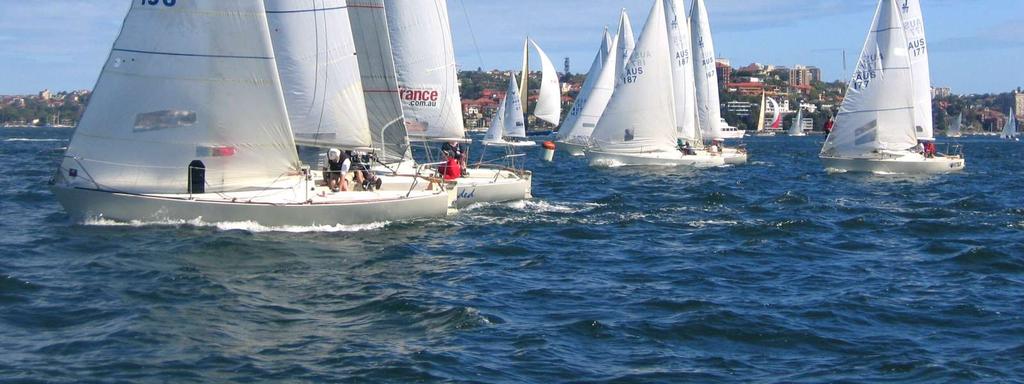
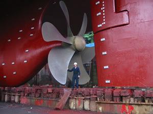
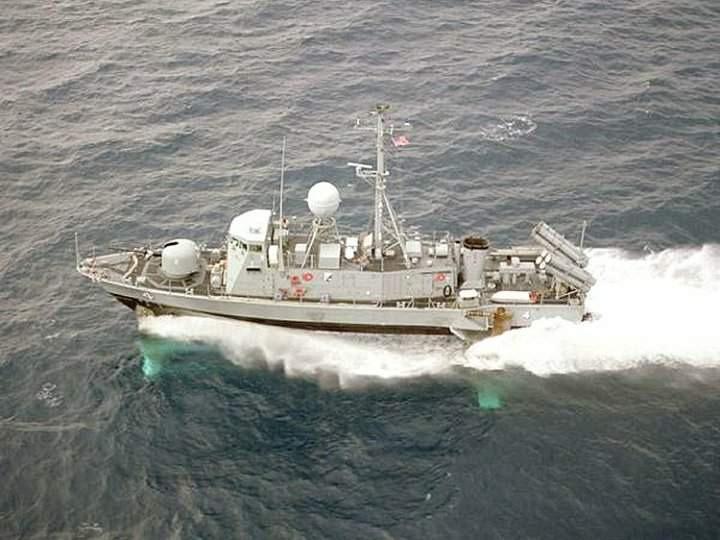
2 Sails > < Keels and rudders Hydrofoils Ship propellers


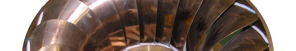
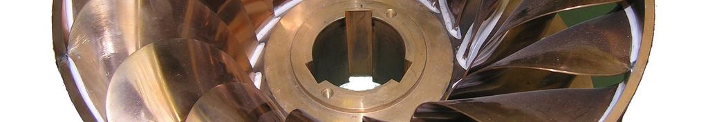


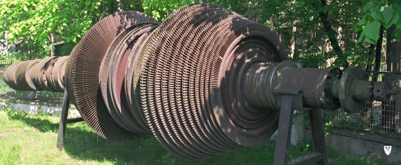
3 Airscrews Steam turbines > Water turbines >


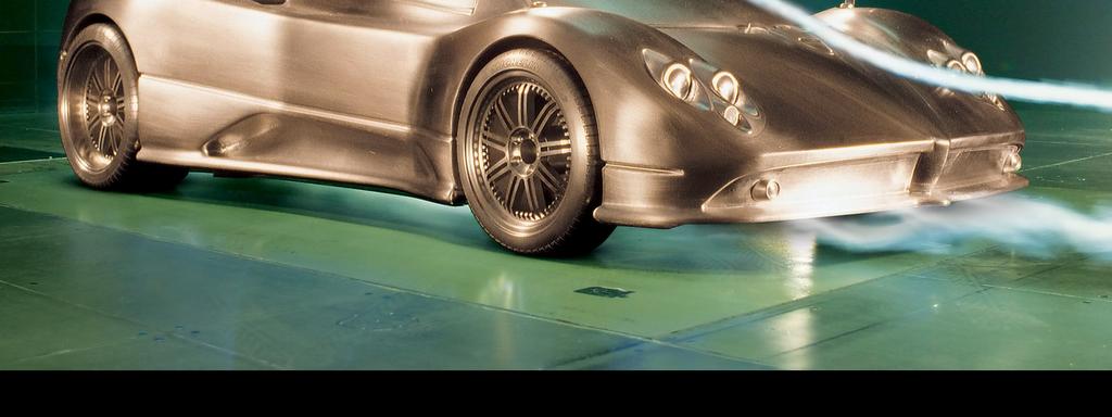
4 Racing cars < Pumps Wind and water turbines >


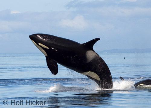
5 Nature always was and still is an inspiration for technology.
6 Aero- or hydrodynamic force is generated on any object placed in a flow. This force may be decomposed into a component perpendicular to the flow velocity, called the lift force and a component parallel to the velocity of flow, called the drag force. The lifting foils are objects shaped in such a way that the maximum lift force and minimum drag force are attained. The characteristics of the foil depend to a large degree on the geometry of its cross-section perpendicular to the foil span, i.e. on the geometry of the aerodynamic profile. P the resultant aerodynamic force P Z - the lift force P X - the drag force M the moment of the aerodynamic force - the flow velocity V α the angle of attack


7 The point of action of the resultant aerodynamic force D changes its location with changing angle of attack, but as a rule it stays near the point F located at the distance 0,25 l from the leading edge, which is called the aerodynamic centre of the profile. The real flow around a lifting foil may be modelled mathematically by means of a vortex:
8 In order to produce the lift force on an airfoil it should be shaped in such a way that a circulatory flow is generated, i.e. the flow is asymmetrical with respect to the direction of the inflow velocity. Then on one side of the profile the velocity of flow increases and simultaneously pressure falls (this is so called suction side), and on the other side the velocity of flow decreases and simultaneously the pressure rises (this is so called pressure side). This pressure difference, acting on the profile generates the lift force. The circulatory flow is achieved either through cambering the airfoil or by setting it at a certain angle with respect to the flow velocity, called the angle of attack. In most cases the appropriate combination of both methods is used.


9 Stream-lines in the flow around a profile Velocity vectors in the flow around a profile


10 Pressure distribution on a profile at the changing angle of attack Distribution of the elementary surface forces on a profile at the changing angle of attack
11 Geometry of the aerodynamic profiles The profiles may be convex-concave (upper sketch), flat-convex (middle sketch), double-convex (lower sketch). Profile chord l is the distance between the two most distant points of the profile. Profile thickness g (or d) is the largest distance perpendicular to the chord limited by the profile contour. The profile shape may be generated by an appropriate superposition of the symmetrical profile and the so called mean line.
12 Mean line is the geometrical location of the centres of circles inscribed into the profile contour. Maximum camber of the mean line f and its location along the chord x f are important parameters. Another important parameter is the location of the maximum thickness x d Experimentally determined characteristics of the several families of airfoils with systematically varied parameters are available. The best known is the NACA profile family (National Advisory Committee for Aeronautics currently NASA): Four digit series, eg. NACA2418: NACA f l x 100 l f d l Five digit series, eg. NACA23012: NACA f l 2x 100 l f d 100 l 100

13 Aerodynamic characteristics of an airfoil The aerodynamic characteristics of a profile include the dependence of the lift and drag coefficients (possibly also moment) on the angle of attack. PZ CZ = ρ 2 V S C X 2 PX = ρ V 2 2 M C M = ρ 2 V 2 ε = C C Z X S Sl coefficient of the profile efficiency where S foil surface area (in case of a profile the area of the foil section of unit span)

14 The form of the aerodynamic characteristics is reflecting the changing conditions of flow around the profile, resulting from the changes in the angle of attack. Moreover, it depends on the profile geometry, Reynolds number and Mach number. At moderate angles of attack the lift force is a linear function of the angle of attack. At high angles of attack the flow separation occurs and the lift force does not grow any further despite increasing angle of attack.
15 Some particular points of the aerodynamic characteristics are important: Zero lift angle is proportional to the relative camber of the profile mean line: f α 0 = k l Maximum lift angle (critical angle of attack) corresponds to the occurence of the developed flow separation on the suction side of the profile. For the profile NACA2418 we have: Optimum angle of attack corresponds to the maximum efficiency of the profile. For the profile NACA2418 we have: = 2,6 α kryt 0 =17,8 0 αopt ε = 20, 6
16 The maximum lift coefficient reaches higher values at higher Reynolds numbers, because then the separation of flow occurs at higher angles of attack.
17 When the aerodynamic characteristics are determined for the foil of finite span, the foil aspect ratio λ is the parameter strongly influencing the form of the characteristics: where: b the foil span If the foil aspect ratio λ is smaller, then the inclination of the lift curve is also smaller and so is the maximum value of the lift coefficient. This results from the increasing effect of the secondary edge flow, which leads to the equilization of pressure difference between the suction and pressure sides of the foil in the regions close to the edges. The value marked λ = denotes the aerodynamic characteristics of the profile. λ = b 2 S
18 On the basis of known aerodynamic characteristics of a profile the characteristics of the finite span foil built of such profiles may be determined. For example for the rectangular outline foil we have: ( + τ ) C 1 α = α + z πλ C x = Cx + C 2 z ( 1+ δ ) πλ With the known lift coefficient and angle of attack of the profile the formula 1 enables determination of the angle of attack of the foil of given span producing the same lift. Formula 2 enables determination of the drag coefficient of the foil at this attack angle, if the profile drag coefficient is known. λ τ δ 3 0,11 0, ,14 0, ,16 0, ,18 0, ,20 0, ,22 0, ,23 0,083
19 The aerodynamic characteristics may be presented in the form of the so called polar diagram. In such a diagram the influence of the foil aspect ratio on the characteristics may be also presented
20 Cascades of profiles Lifting foils forming eg. turbine or pump rotors interact with each other, changing their characteristics. This phenomenon may be analysed on the basis of so called cascade of profiles. inflow velocity - outflow velocity - Accelerating cascade the velocity at outlet is higher than the velocity at inlet (reaction turbines) Neutral cascade modules of the inflow and outflow velocity are identical (impulse turbines) Decelerating cascade the velocity at inlet is higher than the velocity at outlet (pumps) V 1 V 2
21 High lift devices (mainly on aircraft) are used for increasing the lift coefficients at low velocities by changing the profile geometry (mainly increasing their camber).
22 Different high lift devices on aircraft wings


23 Experimental testing and observations of air flow around different objects are performed in wind tunnels A large wind tunnel in Moscow (CAGI) External view of a wind tunnel Inside of the wind tunnel measuring section Six-parameter dynamometer for measuring forces on a model

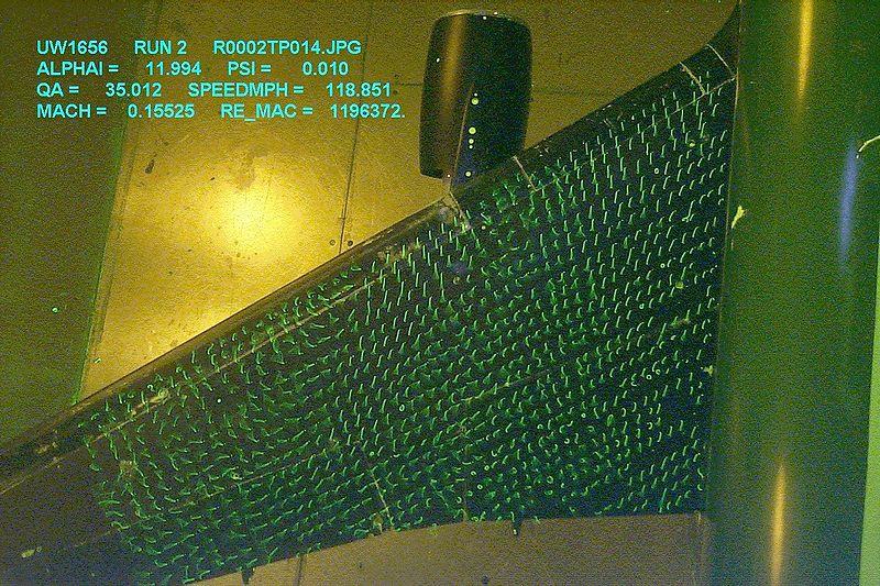
24 Different experiments performed in wind tunnels
The effect of back spin on a table tennis ball moving in a viscous fluid.
 How can planes fly? The phenomenon of lift can be produced in an ideal (non-viscous) fluid by the addition of a free vortex (circulation) around a cylinder in a rectilinear flow stream. This is known as
CFD ANALYSIS OF FLOW AROUND AEROFOIL FOR DIFFERENT ANGLE OF ATTACKS
 www.mechieprojects.com CFD ANALYSIS OF FLOW AROUND AEROFOIL FOR DIFFERENT ANGLE OF ATTACKS PRESENTATION OUTLINE AIM INTRODUCTION LITERATURE SURVEY CFD ANALYSIS OF AEROFOIL RESULTS CONCLUSIONS www.mechieprojects.com
AE Dept., KFUPM. Dr. Abdullah M. Al-Garni. Fuel Economy. Emissions Maximum Speed Acceleration Directional Stability Stability.
 Aerodynamics: Introduction Aerodynamics deals with the motion of objects in air. These objects can be airplanes, missiles or road vehicles. The Table below summarizes the aspects of vehicle performance
AERODYNAMIC CHARACTERISTICS OF NACA 0012 AIRFOIL SECTION AT DIFFERENT ANGLES OF ATTACK
 AERODYNAMIC CHARACTERISTICS OF NACA 0012 AIRFOIL SECTION AT DIFFERENT ANGLES OF ATTACK SUPREETH NARASIMHAMURTHY GRADUATE STUDENT 1327291 Table of Contents 1) Introduction...1 2) Methodology.3 3) Results...5
An Analysis of Lift and Drag Forces of NACA Airfoils Using Python
 An Analysis of Lift and Drag Forces of NACA Airfoils Using Python 1. Tarun B Patel, Sandip T Patel 2, Divyesh T Patel 3, Maulik Bhensdadiya 4 1 M E scholar Government Engineering College, Valsad, Gujarat,
Aerodynamic Analysis of a Symmetric Aerofoil
 214 IJEDR Volume 2, Issue 4 ISSN: 2321-9939 Aerodynamic Analysis of a Symmetric Aerofoil Narayan U Rathod Department of Mechanical Engineering, BMS college of Engineering, Bangalore, India Abstract - The
STUDIES ON THE OPTIMUM PERFORMANCE OF TAPERED VORTEX FLAPS
 ICAS 2000 CONGRESS STUDIES ON THE OPTIMUM PERFORMANCE OF TAPERED VORTEX FLAPS Kenichi RINOIE Department of Aeronautics and Astronautics, University of Tokyo, Tokyo, 113-8656, JAPAN Keywords: vortex flap,
EXPERIMENTAL ANALYSIS OF FLOW OVER SYMMETRICAL AEROFOIL Mayank Pawar 1, Zankhan Sonara 2 1,2
 EXPERIMENTAL ANALYSIS OF FLOW OVER SYMMETRICAL AEROFOIL Mayank Pawar 1, Zankhan Sonara 2 1,2 Assistant Professor,Chandubhai S. Patel Institute of Technology, CHARUSAT, Changa, Gujarat, India Abstract The
Aero Club. Introduction to Flight
 Aero Club Presents Introduction to RC Modeling Module 1 Introduction to Flight Centre For Innovation IIT Madras Page2 Table of Contents Introduction:... 3 How planes fly How is lift generated?... 3 Forces
PRE-TEST Module 2 The Principles of Flight Units /60 points
 PRE-TEST Module 2 The Principles of Flight Units 1-2-3.../60 points 1 Answer the following questions. (20 p.) moving the plane (4) upward / forward. Opposed to that is 1. What are the names of the four
C-1: Aerodynamics of Airfoils 1 C-2: Aerodynamics of Airfoils 2 C-3: Panel Methods C-4: Thin Airfoil Theory
 ROAD MAP... AE301 Aerodynamics I UNIT C: 2-D Airfoils C-1: Aerodynamics of Airfoils 1 C-2: Aerodynamics of Airfoils 2 C-3: Panel Methods C-4: Thin Airfoil Theory AE301 Aerodynamics I : List of Subjects
Welcome to Aerospace Engineering
 Welcome to Aerospace Engineering DESIGN-CENTERED INTRODUCTION TO AEROSPACE ENGINEERING Notes 4 Topics 1. Course Organization 2. Today's Dreams in Various Speed Ranges 3. Designing a Flight Vehicle: Route
Numerical Investigation of Multi Airfoil Effect on Performance Increase of Wind Turbine
 International Journal of Engineering & Applied Sciences (IJEAS) International Journal of Engineering Applied Sciences (IJEAS) Vol.9, Issue 3 (2017) 75-86 Vol.x, Issue x(201x)x-xx http://dx.doi.org/10.24107/ijeas.332075
INVESTIGATION OF PRESSURE CONTOURS AND VELOCITY VECTORS OF NACA 0015IN COMPARISON WITH OPTIMIZED NACA 0015 USING GURNEY FLAP
 INVESTIGATION OF PRESSURE CONTOURS AND VELOCITY VECTORS OF NACA 0015IN COMPARISON WITH OPTIMIZED NACA 0015 USING GURNEY FLAP 1 ANANTH S SHARMA, 2 SUDHAKAR S, 3 SWATHIJAYAKUMAR, 4 B S ANIL KUMAR 1,2,3,4
Incompressible Flow over Airfoils
 Road map for Chap. 4 Incompressible Flow over Airfoils Aerodynamics 2015 fall - 1 - < 4.1 Introduction > Incompressible Flow over Airfoils Incompressible flow over airfoils Prandtl (20C 초 ) Airfoil (2D)
Investigation on 3-D Wing of commercial Aeroplane with Aerofoil NACA 2415 Using CFD Fluent
 Investigation on 3-D of commercial Aeroplane with Aerofoil NACA 2415 Using CFD Fluent Rohit Jain 1, Mr. Sandeep Jain 2, Mr. Lokesh Bajpai 3 1PG Student, 2 Associate Professor, 3 Professor & Head 1 2 3
COMPUTATIONAL FLUID DYNAMIC ANALYSIS OF AIRFOIL NACA0015
 International Journal of Mechanical Engineering and Technology (IJMET) Volume 8, Issue 2, February 2017, pp. 210 219 Article ID: IJMET_08_02_026 Available online at http://www.iaeme.com/ijmet/issues.asp?jtype=ijmet&vtype=8&itype=2
University of Bristol - Explore Bristol Research. Publisher's PDF, also known as Version of record
 Liu, X., Azarpeyvand, M., & Joseph, P. (2015). On the acoustic and aerodynamic performance of serrated airfoils. Paper presented at The 22nd International Congress on Sound and Vibration, Florence, France.
AERODYNAMICS I LECTURE 7 SELECTED TOPICS IN THE LOW-SPEED AERODYNAMICS
 LECTURE 7 SELECTED TOPICS IN THE LOW-SPEED AERODYNAMICS The sources of a graphical material used in this lecture are: [UA] D. McLean, Understanding Aerodynamics. Arguing from the Real Physics. Wiley, 2013.
Reduction of Skin Friction Drag in Wings by Employing Riblets
 Reduction of Skin Friction Drag in Wings by Employing Riblets Kousik Kumaar. R 1 Assistant Professor Department of Aeronautical Engineering Nehru Institute of Engineering and Technology Coimbatore, India
CFD Analysis of Effect of Variation in Angle of Attack over NACA 2412 Airfoil through the Shear Stress Transport Turbulence Model
 IJSRD - International Journal for Scientific Research & Development Vol. 5, Issue 02, 2017 ISSN (online): 2321-0613 CFD Analysis of Effect of Variation in Angle of Attack over NACA 2412 Airfoil through
Aerodynamic Forces on a Wing in a Subsonic Wind Tunnel. Learning Objectives
 Aerodynamic Forces on a Wing in a Subsonic Wind Tunnel AerodynamicForces Lab -1 Learning Objectives 1. Familiarization with aerodynamic forces 2. Introduction to airfoil/wing basics 3. Use and operation
Drag Divergence and Wave Shock. A Path to Supersonic Flight Barriers
 Drag Divergence and Wave Shock A Path to Supersonic Flight Barriers Mach Effects on Coefficient of Drag The Critical Mach Number is the velocity on the airfoil at which sonic flow is first acquired If
ROAD MAP... D-1: Aerodynamics of 3-D Wings D-2: Boundary Layer and Viscous Effects D-3: XFLR (Aerodynamics Analysis Tool)
") Unit D-1: Aerodynamics of 3-D Wings Page 1 of 5 AE301 Aerodynamics I UNIT D: Applied Aerodynamics ROAD MAP... D-1: Aerodynamics of 3-D Wings D-: Boundary Layer and Viscous Effects D-3: XFLR (Aerodynamics
Unit D-1: Aerodynamics of 3-D Wings Page 1 of 5 AE301 Aerodynamics I UNIT D: Applied Aerodynamics ROAD MAP... D-1: Aerodynamics of 3-D Wings D-: Boundary Layer and Viscous Effects D-3: XFLR (Aerodynamics
CFD Study of Solid Wind Tunnel Wall Effects on Wing Characteristics
 Indian Journal of Science and Technology, Vol 9(45), DOI :10.17485/ijst/2016/v9i45/104585, December 2016 ISSN (Print) : 0974-6846 ISSN (Online) : 0974-5645 CFD Study of Solid Wind Tunnel Wall Effects on
DESIGN OF AN AERODYNAMIC MEASUREMENT SYSTEM FOR UNMANNED AERIAL VEHICLE AIRFOILS
 DESIGN OF AN AERODYNAMIC MEASUREMENT SYSTEM FOR UNMANNED AERIAL VEHICLE AIRFOILS L. Velázquez-Araque 1 and J. Nožička 1 1 Department of Fluid Dynamics and Power Engineering, Faculty of Mechanical Engineering
Prognosis of Rudder Cavitation Risk in Ship Operation
 Prognosis of Rudder Cavitation Risk in Ship Operation Lars Greitsch, TUHH, Hamburg/Germany, lars.greitsch@tu-harburg.de 1 Introduction In the course of increase of the requirements, the necessity of more
Senior mechanical energy conversion trends
 Senior mechanical energy conversion trends Introduction and Analysis to fan blade profile and CFD Simulation Of An Appropriate Blade Profile for improving energy efficiency HAMED ROSTAMALIZADEH 95742906
AERODYNAMIC CHARACTERISTICS OF SPIN PHENOMENON FOR DELTA WING
 ICAS 2002 CONGRESS AERODYNAMIC CHARACTERISTICS OF SPIN PHENOMENON FOR DELTA WING Yoshiaki NAKAMURA (nakamura@nuae.nagoya-u.ac.jp) Takafumi YAMADA (yamada@nuae.nagoya-u.ac.jp) Department of Aerospace Engineering,
Aerodynamic Analysis of Blended Winglet for Low Speed Aircraft
 , July 1-3, 2015, London, U.K. Aerodynamic Analysis of Blended Winglet for Low Speed Aircraft Pooja Pragati, Sudarsan Baskar Abstract This paper provides a practical design of a new concept of massive
CASE STUDY FOR USE WITH SECTION B
 GCE A level 135/01-B PHYSICS ASSESSMENT UNIT PH5 A.M. THURSDAY, 0 June 013 CASE STUDY FOR USE WITH SECTION B Examination copy To be given out at the start of the examination. The pre-release copy must
Aircraft Stability and Performance 2nd Year, Aerospace Engineering. Dr. M. Turner
 Aircraft Stability and Performance 2nd Year, Aerospace Engineering Dr. M. Turner Basic Info Timetable 15.00-16.00 Monday Physics LTA 16.00-17.00 Monday Physics LTA Exam 2 1 2 hour exam 6 questions 2 from
STUDY OF VARIOUS NACA SERIES AEROFOIL SECTIONS AND WING CONTOUR GENERATION USING CATIA V5
 STUDY OF VARIOUS NACA SERIES AEROFOIL SECTIONS AND WING CONTOUR GENERATION USING CATIA V5 Pawan Kumar Department of Aeronautical Engineering, Desh Bhagat University, Punjab, India ABSTRACT Aerofoil is
ROTORS for WIND POWER
 ROTORS for WIND POWER P.T. Smulders Wind Energy Group Faculty of Physics University of Technology, Eindhoven ARRAKIS 1 st edition October 1991 revised edition January 2004 CONTENTS ROTORS for WIND POWER...
OUTLINE FOR Chapter 4
 16/8/3 OUTLINE FOR Chapter AIRFOIL NOMENCLATURE The leaing ege circle: (usually raius =. chor length c) The trailing ege: The chor line: Straight line connecting the center of leaing ege circle an the
FABRICATION OF VERTICAL AXIS WIND TURBINE WITH WIND REDUCER AND EXPERIMENTAL INVESTIGATIONS
 87 CHAPTER-4 FABRICATION OF VERTICAL AXIS WIND TURBINE WITH WIND REDUCER AND EXPERIMENTAL INVESTIGATIONS 88 CHAPTER-4 FABRICATION OF VERTICAL AXIS WIND TURBINE WITH WIND REDUCER AND EXPERIMENTAL INVESTIGATIONS
INVESTIGATION OF HYDRODYNAMIC PERFORMANCE OF HIGH-SPEED CRAFT RUDDERS VIA TURBULENT FLOW COMPUTATIONS, PART I: NON-CAVITATING CHARACTERISTICS
 Journal of Marine Science and Technology, Vol. 13, No. 1, pp. 61-72 (2005) 61 Short Paper INVESTIGATION OF HYDRODYNAMIC PERFORMANCE OF HIGH-SPEED CRAFT RUDDERS VIA TURBULENT FLOW COMPUTATIONS, PART I:
NUMERICAL INVESTIGATION FOR THE ENHANCEMENT OF THE AERODYNAMIC CHARACTERISTICS OF AN AEROFOIL BY USING A GURNEY FLAP
 Geotec., Const. Mat. & Env., ISSN:2186-2990, Japan, DOI: http://dx.doi.org/10.21660/2017.34.2650 NUMERICAL INVESTIGATION FOR THE ENHANCEMENT OF THE AERODYNAMIC CHARACTERISTICS OF AN AEROFOIL BY USING A
Computational Analysis of Cavity Effect over Aircraft Wing
 World Engineering & Applied Sciences Journal 8 (): 104-110, 017 ISSN 079-04 IDOSI Publications, 017 DOI: 10.589/idosi.weasj.017.104.110 Computational Analysis of Cavity Effect over Aircraft Wing 1 P. Booma
Aerofoil Profile Analysis and Design Optimisation
 Journal of Aerospace Engineering and Technology Volume 3, Issue 2, ISSN: 2231-038X Aerofoil Profile Analysis and Design Optimisation Kondapalli Siva Prasad*, Vommi Krishna, B.B. Ashok Kumar Department
CFD ANALYSIS OF EFFECT OF FLOW OVER NACA 2412 AIRFOIL THROUGH THE SHEAR STRESS TRANSPORT TURBULENCE MODEL
 CFD ANALYSIS OF EFFECT OF FLOW OVER NACA 2412 AIRFOIL THROUGH THE SHEAR STRESS TRANSPORT TURBULENCE MODEL 1 SHIVANANDA SARKAR, 2SHAHEEN BEG MUGHAL 1,2 Department of Mechanical Engineering, ITM University,
Evaluation of aerodynamic criteria in the design of a small wind turbine with the lifting line model
 Evaluation of aerodynamic criteria in the design of a small wind turbine with the lifting line model Nicolas BRUMIOUL Abstract This thesis deals with the optimization of the aerodynamic design of a small
Aerodynamic Terms. Angle of attack is the angle between the relative wind and the wing chord line. [Figure 2-2] Leading edge. Upper camber.
![Aerodynamic Terms. Angle of attack is the angle between the relative wind and the wing chord line. [Figure 2-2] Leading edge. Upper camber.](/thumbs/82/86661300.jpg "Aerodynamic Terms. Angle of attack is the angle between the relative wind and the wing chord line. [Figure 2-2] Leading edge. Upper camber.") Chapters 2 and 3 of the Pilot s Handbook of Aeronautical Knowledge (FAA-H-8083-25) apply to powered parachutes and are a prerequisite to reading this book. This chapter will focus on the aerodynamic fundamentals
Chapters 2 and 3 of the Pilot s Handbook of Aeronautical Knowledge (FAA-H-8083-25) apply to powered parachutes and are a prerequisite to reading this book. This chapter will focus on the aerodynamic fundamentals
Lift for a Finite Wing. all real wings are finite in span (airfoils are considered as infinite in the span)
") Lift for a Finite Wing all real wings are finite in span (airfoils are considered as infinite in the span) The lift coefficient differs from that of an airfoil because there are strong vortices produced
Lift for a Finite Wing all real wings are finite in span (airfoils are considered as infinite in the span) The lift coefficient differs from that of an airfoil because there are strong vortices produced
ANALYSIS OF AERODYNAMIC CHARACTERISTICS OF A SUPERCRITICAL AIRFOIL FOR LOW SPEED AIRCRAFT
 ANALYSIS OF AERODYNAMIC CHARACTERISTICS OF A SUPERCRITICAL AIRFOIL FOR LOW SPEED AIRCRAFT P.Sethunathan 1, M.Niventhran 2, V.Siva 2, R.Sadhan Kumar 2 1 Asst.Professor, Department of Aeronautical Engineering,
EFFECT OF GURNEY FLAPS AND WINGLETS ON THE PERFORMANCE OF THE HAWT
 Chapter-6 EFFECT OF GURNEY FLAPS AND WINGLETS ON THE PERFORMANCE OF THE HAWT 6.1 Introduction The gurney flap (wicker bill) was a small flat tab projecting from the trailing edge of a wing. Typically it
Incompressible Potential Flow. Panel Methods (3)
") Incompressible Potential Flow Panel Methods (3) Outline Some Potential Theory Derivation of the Integral Equation for the Potential Classic Panel Method Program PANEL Subsonic Airfoil Aerodynamics Issues
Incompressible Potential Flow Panel Methods (3) Outline Some Potential Theory Derivation of the Integral Equation for the Potential Classic Panel Method Program PANEL Subsonic Airfoil Aerodynamics Issues
BUILD AND TEST A WIND TUNNEL
 LAUNCHING INTO AVIATION 9 2018 Aircraft Owners and Pilots Association. All Rights Reserved. UNIT 2 SECTION D LESSON 2 PRESENTATION BUILD AND TEST A WIND TUNNEL LEARNING OBJECTIVES By the end of this lesson,
Jet Propulsion. Lecture-17. Ujjwal K Saha, Ph. D. Department of Mechanical Engineering Indian Institute of Technology Guwahati
 Lecture-17 Prepared under QIP-CD Cell Project Jet Propulsion Ujjwal K Saha, Ph. D. Department of Mechanical Engineering Indian Institute of Technology Guwahati 1 Lift: is used to support the weight of
Aerodynamic Analyses of Horizontal Axis Wind Turbine By Different Blade Airfoil Using Computer Program
 ISSN : 2250-3021 Aerodynamic Analyses of Horizontal Axis Wind Turbine By Different Blade Airfoil Using Computer Program ARVIND SINGH RATHORE 1, SIRAJ AHMED 2 1 (Department of Mechanical Engineering Maulana
Incompressible Flow over Airfoils
 < 4.7 Classical Thin Airfoil Theory > The Symmetric Airfoil * Assumptions Incompressible Flow over Airfoils i) The camber line is one of the streamlines ii) Small maximum camber and thickness relative
Induced Drag Reduction for Modern Aircraft without Increasing the Span of the Wing by Using Winglet
 International Journal of Mechanical & Mechatronics Engineering IJMME-IJENS Vol:10 No:03 49 Induced Drag Reduction for Modern Aircraft without Increasing the Span of the Wing by Using Winglet Mohammad Ilias
CFD Analysis of Supercritical Airfoil with Different Camber
 CFD Analysis of Supercritical Airfoil with Different Camber S.Manikandan 1, R.G.Bhuvana 2, Sowmya.A.Srinivasan 3 Assistant prof, Department of Aeronautical Engineering, Jeppiaar Engineering College, Chennai,
External Tank- Drag Reduction Methods and Flow Analysis
 External Tank- Drag Reduction Methods and Flow Analysis Shaik Mohammed Anis M.Tech Student, MLR Institute of Technology, Hyderabad, India. G. Parthasarathy Associate Professor, MLR Institute of Technology,
CFD Analysis ofwind Turbine Airfoil at Various Angles of Attack
 IOSR Journal of Mechanical and Civil Engineering (IOSR-JMCE) e-issn: 2278-1684,p-ISSN: 2320-334X, Volume 13, Issue 4 Ver. II (Jul. - Aug. 2016), PP 18-24 www.iosrjournals.org CFD Analysis ofwind Turbine
No Description Direction Source 1. Thrust
 AERODYNAMICS FORCES 1. WORKING TOGETHER Actually Lift Force is not the only force working on the aircraft, during aircraft moving through the air. There are several aerodynamics forces working together
Computational Analysis of the S Airfoil Aerodynamic Performance
 Computational Analysis of the 245-3S Airfoil Aerodynamic Performance Luis Velazquez-Araque and Jiří Nožička 2 Department of Mechanical Engineering National University of Táchira, San Cristóbal 5, Venezuela
PERFORMANCE OF A FLAPPED DUCT EXHAUSTING INTO A COMPRESSIBLE EXTERNAL FLOW
 24 TH INTERNATIONAL CONGRESS OF THE AERONAUTICAL SCIENCES PERFORMANCE OF A FLAPPED DUCT EXHAUSTING INTO A COMPRESSIBLE EXTERNAL FLOW P. R. Pratt, J. K. Watterson, E. Benard, S. Hall School of Aeronautical
INTERFERENCE EFFECT AND FLOW PATTERN OF FOUR BIPLANE CONFIGURATIONS USING NACA 0024 PROFILE
 Proceedings of the International Conference on Mechanical Engineering 211 (ICME211) 18-2 December 211, Dhaka, Bangladesh ICME11-FL-1 INTERFERENCE EFFECT AND FLOW PATTERN OF FOUR BIPLANE CONFIGURATIONS
International Journal of Innovative Research in Science, Engineering and Technology Vol. 2, Issue 5, May 2013
 PERFORMANCE PREDICTION OF HORIZONTAL AXIS WIND TURBINE BLADE HardikPatel 1, SanatDamania 2 Master of Engineering Student, Department of Mechanical Engineering, Government Engineering College, Valsad, Gujarat,
OBJECTIVE METHODOLOGY
 SKMA394 Measurement of Pressure Distribution around an Airfoil NACA445 OBJECTIVE The objective of this experiment is to study about the pressure distribution around the surface of aerofoil NACA 445 starting
Aerodynamic Design, Fabrication and Testing of Wind Turbine Rotor Blades
 Aerodynamic Design, Fabrication and Testing of Wind Turbine Rotor Blades T.Mahendrapandian Department of Mechanical Engineering P.G. Student, Regional Centre of Anna University, Tirunelveli, Tamilnadu,
Figure 1 Figure 1 shows the involved forces that must be taken into consideration for rudder design. Among the most widely known profiles, the most su
 THE RUDDER starting from the requirements supplied by the customer, the designer must obtain the rudder's characteristics that satisfy such requirements. Subsequently, from such characteristics he must
SEMI-SPAN TESTING IN WIND TUNNELS
 25 TH INTERNATIONAL CONGRESS OF THE AERONAUTICAL SCIENCES SEMI-SPAN TESTING IN WIND TUNNELS S. Eder, K. Hufnagel, C. Tropea Chair of Fluid Mechanics and Aerodynamics, Darmstadt University of Technology
Power efficiency and aerodynamic forces measurements on the Dettwiler-wind turbine
 Institut für Fluiddynamik ETH Zentrum, ML H 33 CH-8092 Zürich P rof. Dr. Thomas Rösgen Sonneggstrasse 3 Telefon +41-44-632 2646 Fax +41-44-632 1147 roesgen@ifd.mavt.ethz.ch www.ifd.mavt.ethz.ch Power efficiency
AF101 to AF109. Subsonic Wind Tunnel Models AERODYNAMICS. A selection of optional models for use with TecQuipment s Subsonic Wind Tunnel (AF100)
") Page 1 of 4 A selection of optional models for use with TecQuipment s Subsonic Wind Tunnel (AF100) Dimpled Sphere Drag Model (from AF109) shown inside the TecQuipment AF100 Wind Tunnel. Cylinder, aerofoils,
Page 1 of 4 A selection of optional models for use with TecQuipment s Subsonic Wind Tunnel (AF100) Dimpled Sphere Drag Model (from AF109) shown inside the TecQuipment AF100 Wind Tunnel. Cylinder, aerofoils,
Chapter 5 Wing design - selection of wing parameters - 3 Lecture 21 Topics
 Chapter 5 Wing design - selection of wing parameters - 3 Lecture 21 Topics 5.3.2 Choice of sweep ( ) 5.3.3 Choice of taper ratio ( λ ) 5.3.4 Choice of twist ( ε ) 5.3.5 Wing incidence(i w ) 5.3.6 Choice
Low Speed Thrust Characteristics of a Modified Sonic Arc Airfoil Rotor through Spin Test Measurement
 Technical Paper Int l J. of Aeronautical & Space Sci. 13(3), 317 322 (2012) DOI:10.5139/IJASS.2012.13.3.317 Low Speed Thrust Characteristics of a Modified Sonic Arc Airfoil Rotor through Spin Test Measurement
The subsonic compressibility effect is added by replacing. with
 Swept Wings The main function of a swept wing is to reduce wave drag at transonic and supersonic speeds. Consider a straight wing and a swept wing in a flow with a free-stream velocity V. Assume that the
AERODYNAMIC ANALYSIS OF MULTI-WINGLETS FOR LOW SPEED AIRCRAFT
 AERODYNAMIC ANALYSIS OF MULTI-WINGLETS FOR LOW SPEED AIRCRAFT Cosin, R., Catalano, F.M., Correa, L.G.N., Entz, R.M.U. Engineering School of São Carlos - University of São Paulo Keywords: multi-winglets,
Basic Fluid Mechanics
 Basic Fluid Mechanics Chapter 7B: Forces on Submerged Bodies 7/26/2018 C7B: Forces on Submerged Bodies 1 Forces on Submerged Bodies Lift and Drag are forces exerted on an immersed body by the surrounding
5 th European Conference on Turbomaschinery - Fluid Dynamics and Thermodynamics in Prague in March 2003
 5 th European Conference on Turbomaschinery - Fluid Dynamics and Thermodynamics in Prague in March 2003 Secondary flow control on compressor blades to improve the performance of axial turbomachines R.
Experimental and Theoretical Investigation for the Improvement of the Aerodynamic Characteristic of NACA 0012 airfoil
 International Journal of Mining, Metallurgy & Mechanical Engineering (IJMMME) Volume 2, Issue 1 (214) ISSN 232 46 (Online) Experimental and Theoretical Investigation for the Improvement of the Aerodynamic
COMPUTER-AIDED DESIGN AND PERFORMANCE ANALYSIS OF HAWT BLADES
 5 th International Advanced Technologies Symposium (IATS 09), May 13-15, 2009, Karabuk, Turkey COMPUTER-AIDED DESIGN AND PERFORMANCE ANALYSIS OF HAWT BLADES Emrah KULUNK a, * and Nadir YILMAZ b a, * New
DEFINITIONS. Aerofoil
 Aerofoil DEFINITIONS An aerofoil is a device designed to produce more lift (or thrust) than drag when air flows over it. Angle of Attack This is the angle between the chord line of the aerofoil and the
Laminar Flow Sections for Proa Boards and Rudders
 Laminar Flow Sections for Proa Boards and Rudders Thomas E. Speer, Des Moines, Washington, USA ABSTRACT Hydrofoil section designs for proa sailboats which reverse direction in a shunt when changing tacks
Aerodynamic Performance Optimization Of Wind Turbine Blade By Using High Lifting Device
 Aerodynamic Performance Optimization Of Wind Turbine Blade By Using High Lifting Device Razeen Ridhwan, Mohamed Alshaleeh, Arunvinthan S Abstract: In the Aerodynamic performance of wind turbine blade by
Subsonic wind tunnel models
 aerodynamics AF1300a to AF1300l A selection of optional models for use with TecQuipment s Subsonic Wind Tunnel (AF1300) Dimpled Sphere Drag Model (from AF1300j) shown inside the TecQuipment AF1300 Wind
CFD AND EXPERIMENTAL STUDY OF AERODYNAMIC DEGRADATION OF ICED AIRFOILS
 Colloquium FLUID DYNAMICS 2008 Institute of Thermomechanics AS CR, v.v.i., Prague, October 22-24, 2008 p.1 CFD AND EXPERIMENTAL STUDY OF AERODYNAMIC DEGRADATION OF ICED AIRFOILS Vladimír Horák 1, Dalibor
Aerodynamic Modification of CFR Formula SAE Race Car
 Aerodynamic Modification of CFR Formula SAE Race Car Brandon M. Verhun, Trevor D. Haight, and Thomas A. Mahank Department of Mechanical Engineering Saginaw Valley State University University Center, MI
Model tests of wind turbine with a vertical axis of rotation type Lenz 2
 Model tests of wind turbine with a vertical axis of rotation type Lenz 2 Jaroslaw Zwierzchowski 1,*, Pawel Andrzej Laski 1, Slawomir Blasiak 1, Jakub Emanuel Takosoglu 1, Dawid Sebastian Pietrala 1, Gabriel
EXPERIMENTAL INVESTIGATION OF LIFT & DRAG PERFORMANCE OF NACA0012 WIND TURBINE AEROFOIL
 EXPERIMENTAL INVESTIGATION OF LIFT & DRAG PERFORMANCE OF NACA0012 WIND TURBINE AEROFOIL Mr. Sandesh K. Rasal 1, Mr. Rohan R. Katwate 2 1 PG Student, 2 Assistant Professor, DYPSOEA Ambi Talegaon, Heat Power
SOARING AND GLIDING FLIGHT OF THE BLACK VULTURE
 [ 280 ] SOARING AND GLIDING FLIGHT OF THE BLACK VULTURE BY B. G. NEWMAN* Department of Engineering, University of Cambridge {Received 10 September 1957) INTRODUCTION In 1950 Raspet published an interesting
AN EXPERIMENTAL STUDY OF THE EFFECTS OF SWEPT ANGLE ON THE BOUNDARY LAYER OF THE 2D WING
 AN EXPERIMENTAL STUDY OF THE EFFECTS OF SWEPT ANGLE ON THE BOUNDARY LAYER OF THE 2D WING A. Davari *, M.R. Soltani, A.Tabrizian, M.Masdari * Assistant Professor, Department of mechanics and Aerospace Engineering,
The Fly Higher Tutorial IV
 The Fly Higher Tutorial IV THE SCIENCE OF FLIGHT In order for an aircraft to fly we must have two things: 1) Thrust 2) Lift Aerodynamics The Basics Representation of the balance of forces These act against
THEORY OF WINGS AND WIND TUNNEL TESTING OF A NACA 2415 AIRFOIL. By Mehrdad Ghods
 THEORY OF WINGS AND WIND TUNNEL TESTING OF A NACA 2415 AIRFOIL By Mehrdad Ghods Technical Communication for Engineers The University of British Columbia July 23, 2001 ABSTRACT Theory of Wings and Wind
Aerodynamics Principles
 Aerodynamics Principles Stage 1 Ground Lesson 3 Chapter 3 / Pages 2-18 3:00 Hrs Harold E. Calderon AGI, CFI, CFII, and MEI Lesson Objectives Become familiar with the four forces of flight, aerodynamic
International Engineering Research Journal Experimental & Numerical Investigation of Lift & Drag Performance of NACA0012 Wind Turbine Aerofoil
 International Engineering Research Journal Experimental & Numerical Investigation of Lift & Drag Performance of NACA0012 Wind Turbine Aerofoil Mr. Sandesh K. Rasal, Mr. Rohan R. Katwate PG student of Department
Low Speed Wind Tunnel Wing Performance
 Low Speed Wind Tunnel Wing Performance ARO 101L Introduction to Aeronautics Section 01 Group 13 20 November 2015 Aerospace Engineering Department California Polytechnic University, Pomona Team Leader:
Aerofoil Design for Man Powered Aircraft
 Man Powered Aircraft Group Aerofoil Design for Man Powered Aircraft By F. X. Wortmann Universitat Stuttgart From the Second Man Powered Aircraft Group Symposium Man Powered Flight The Way Ahead 7 th February
Numerical Analysis of Wings for UAV based on High-Lift Airfoils
 Numerical Analysis of Wings for UAV based on High-Lift Airfoils Sachin Srivastava Department of Aeronautical Engineering Malla Reddy College of Engineering & Technology, Hyderabad, Telangana, India Swetha
THE COLLEGE OF AERONAUTICS CRANFIELD
 THE COLLEGE OF AERONAUTICS CRANFIELD AERODYNAMIC CHARACTERISTICS OF A 40 SWEPT BACK WING OF ASPECT RATIO 4.5 by P. S. BARNA NOTE NO. 65 MAY, 1957 CRANFIELD A preliminary report on the aerodynamic characteristics
It should be noted that the symmetrical airfoil at zero lift has no pitching moment about the aerodynamic center because the upper and
 NAVWEPS -81-8 and high power, the dynamic pressure in the shaded area can be much greater than the free stream and this causes considerably greater lift than at zero thrust. At high power conditions the
Performance Analysis of the Flying Wing Airfoils
 Performance Analysis of the Flying Wing Airfoils PRISACARIU Vasile Henri Coandă Air Force Academy, Brașov, Romania, aerosavelli73@yahoo.com Abstract Flying wings flight performances depend directly on
Numerical Simulation And Aerodynamic Performance Comparison Between Seagull Aerofoil and NACA 4412 Aerofoil under Low-Reynolds 1
 Advances in Natural Science Vol. 3, No. 2, 2010, pp. 244-20 www.cscanada.net ISSN 171-7862 [PRINT] ISSN 171-7870 [ONLINE] www.cscanada.org *The 3rd International Conference of Bionic Engineering* Numerical
Experimental study on aerodynamic characteristics of vertical-axis wind turbine
 International Journal of Smart Grid and Clean Energy Experimental study on aerodynamic characteristics of vertical-axis wind turbine Yihuai Hu a*, Taiyou Wang a, Hao Jin a, Xianfeng Cao b, Chen Zhang b
Volume 8, ISSN (Online), Published at:
, Published at:") EW PERSPECTIVE VERSIO OF BI-DARRIES WIDTRBIE Ainakul Yershina Kazakh ational niversity named by al-farabi, Research Institute of Mechanics & Matematics. (Avenue al-farabi 71, Almaty, Kazakhstan) Abstract
EW PERSPECTIVE VERSIO OF BI-DARRIES WIDTRBIE Ainakul Yershina Kazakh ational niversity named by al-farabi, Research Institute of Mechanics & Matematics. (Avenue al-farabi 71, Almaty, Kazakhstan) Abstract
Investigation and Comparison of Airfoils
 AENG 360 Aerodynamics Investigation and Comparison of Airfoils Rocie Benavent Chelseyann Bipat Brandon Gilyard Julian Marcon New York Institute of Technology Fall 2013 2 Executive Summary Airfoil design
Aerodynamic Basics Larry Bogan - Jan 2002 version MECHANICS
 Aerodynamic Basics Larry Bogan - Jan 2002 version MECHANICS Vectors Force, displacement, acceleration, and velocity Inertia and Velocity Inertia is a property of mass. (When there is no force on an object,
Efficiency Improvement of a New Vertical Axis Wind Turbine by Individual Active Control of Blade Motion
 Efficiency Improvement of a New Vertical Axis Wind Turbine by Individual Active Control of Blade Motion In Seong Hwang, Seung Yong Min, In Oh Jeong, Yun Han Lee and Seung Jo Kim* School of Mechanical &