C3101 Briefing Guide (Worksheet)
|
|
|
- Gilbert Little
- 5 years ago
- Views:
Transcription
 Planned Route: Takeoff: KNSE, Rwy 32 Altitude: Working area limits Route: NMOA or Pelican, Brewton or Evergreen, KNSE Training")
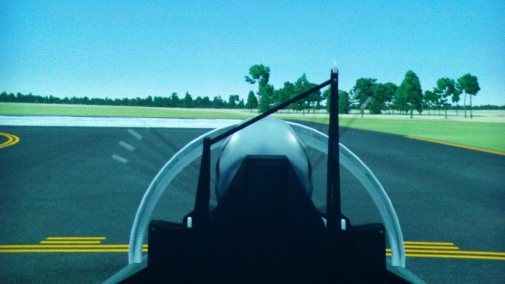
1 T-6B JPPT B Simulator Event Briefing Guide C3101 Briefing Guide (Worksheet) Planned Route: Takeoff: KNSE, Rwy 32 Altitude: Working area limits Route: NMOA or Pelican, Brewton or Evergreen, KNSE Training Device: OFT SYLLABUS NOTES: All maneuvers performed by the IUT will emphasize instructional procedures while maintaining pilot proficiency level from the rear cockpit. Event shall be conducted using rear cockpit view. Not all the required plus (+) items are listed within the discussion points in the MCG. In order to accommodate the completion of all required items by EOB some items have been added or moved between the three events within the block. Use Abbreviated Simulator checklist to expedite becoming airborne. Once airborne all applicable checklist will be conducted from the quad-fold version. Special Syllabus Requirement: None Maneuvers to be performed IAW Contact FTI: a. Takeoff b. Departure FTI FWOP c. Turn Pattern d. Level Speed Change e. Slow Flight (SCATSAFE) Slow Flight (Student Maneuver) f. Power-on Stall g. Power-Off Stall (ELP Stall) h. Landing Pattern (Approach Turn) Stall Ejection Seat Sequence Mitigation Procedures JPPT B C3101
2 CNATRAINST B IUT T-6B DAY CONTACT C3100 BLOCK IUT GRADE SHEET DATE INSTRUCTOR MEDIA: OFT VT- BRIEF TIME: NAME: EVENT: CTS MANEUVER REF MIF C3101 C3102 C GENERAL KNOWLEDGE / PROCEDURES 4+ X X X 2 EMERGENCY PROCEDURES 4+ X X X 3 HEADWORK / SITUATIONAL AWARENESS 4+ X X X 4 BASIC AIRWORK 4+ X X X 5 IN-FLIGHT CHECKS / FUEL MANAGEMENT 4+ X X X 6 IN-FLIGHT PLANNING / 4+ X X X AREA ORIENTATION 7 TASK MANAGEMENT 4+ X X X 8 COMMUNICATION 4+ X X X 9 MISSION PLANNING / BRIEFING / 3+ X X X DEBRIEFING 10 GROUND OPERATIONS 4 11 TAKEOFF 4+ X X X 12 DEPARTURE 4+ X X X 13 INSRUCTIONAL SKILLS / STUDENT 3+ X X X MANAGEMENT 15 TURN PATTERN 3+ X 16 LEVEL SPEED CHANGE 3+ X 17 SLOW FLIGHT 3+ X 18 POWER-ON STALL 3+ X 19 LANDING PATTERN STALLS 3+ X 20 EMERGENCY LANDING PATTERN STALLS 3+ X 21 SPIN 3 22 CONTACT UNUSUAL ATTITUDES 3+ X 23 LOOP 3+ X 24 AILERON ROLL 3+ X 25 SPLIT-S 3+ X 26 BARREL ROLL 3+ X 27 CLOVERLEAF 3+ X 28 IMMELMANN 3+ X 29 CUBAN EIGHT 3+ X 30 WINGOVER 3+ X 31 SLIP 3 32 POWER LOSS 3+ X 33 PRECAUTIONARY EMERGENCY LANDING 3+ X 34 PEL/P 3+ X 35 ELP LANDING 3+ X 36 VFR ARRIVAL / COURSE RULES 3 37 LANDING PATTERN 3+ X 38 NO FLAP LANDING 3+ X 38 TAKEOFF FLAP LANDING 3+ X 38 LDG FLAP LANDING 3+ X 39 AOA PATTERN 3+ X 40 WAVEOFF 4 Note: All maneuvers performed by the IUT will emphasize instructional procedures while maintaining pilot proficiency level. PFIT B 03/16/2017

3 CHAPTER FIVE 504. COMMUNICATIONS Proper radio communication procedures are extremely important to safety when operating in controlled airspace or the vicinity of other aircraft. You should read and learn the basic communication terminology/procedures explained in Appendix B. These procedures will be used throughout your aviation career TAKEOFF 1. Description. Takeoff is the movement of the aircraft from its starting point on the runway until it leaves the ground in controlled flight. 2. General. The takeoff requires a smooth transition from ground roll to controlled flight. Although a relatively simple maneuver, the takeoff presents numerous potential hazards. The dynamics of high engine thrust, possible directional control problems, the potential for runway incursions, high-speed aborts, low-altitude engine failures, to name a few, make the takeoff regime of flight unique in its safety challenges. Thorough and disciplined ground operations help lead to a safe, uneventful takeoff. Takeoffs should always be made as nearly into the wind as practical. The aircraft s ground speed in a headwind is slower at liftoff than in a tailwind, thus reducing wear and stress on the landing gear. Secondly, a shorter distance is required to develop the minimum lift necessary for takeoff and climb. Aircraft depend on airspeed to fly. A headwind provides some airspeed before the aircraft even begins its takeoff ground roll as the wind flows over the wings. Although the takeoff and climb process is one continuous maneuver, it is divided into three separate steps for purposes of explanation: takeoff roll, rotation, and initial climb (Figure 5-2). Figure 5-2 The Takeoff Roll, Rotation, and Initial Climb FLIGHT PROCEDURES 5-3
4 CHAPTER FIVE The takeoff roll is the portion of the takeoff procedure during which the aircraft is accelerated from a standstill to an airspeed providing sufficient lift for it to become airborne. The rotation is the act of raising the nose of the aircraft to a set pitch attitude, increasing AOA and allowing the aircraft to become airborne in controlled flight. The initial climb is the period just after the aircraft has left the runway and is normally considered complete when the aircraft has reached a safe maneuvering altitude. During the takeoff, an abrupt application of power will cause the aircraft to yaw sharply left because of the torque effects of the propeller. Steady the yawing tendency with right rudder as the engine spools up and the aircraft begins rolling down the runway. Remember, the TAD will not begin making rudder trim adjustments until 80 KIAS and weight off wheels. As speed increases, more and more pressure will be felt on the flight controls, particularly the elevator and rudder. Since the tail surfaces receive the full effect of the propeller slipstream, they become effective first. To rotate, apply back stick pressure at 85 KIAS to gradually raise the nose wheel off the runway and establish the takeoff attitude (8º nose high, spinner on or slightly below the horizon). This is referred to as rotating. Allow the aircraft to fly itself off the ground. Do not force the aircraft into the air with excessive back-stick pressure as this will only result in an excessively high pitch attitude, possible stall or tail strike. Coordinate right rudder as necessary with TAD adjustments during rotation. Compensate for the left yaw tendency as the aircraft leaves the runway with rudder, not aileron. As you move to the initial climb phase of the takeoff, check pitch attitude at approximately 8 nose high and begin accelerating. The aircraft will pick up speed rapidly after becoming airborne. Once a positive climb is verified and a safe landing cannot be made on the remaining runway in front of you, raise the gear and flaps (as per After Takeoff Checklist and the procedures below). Accelerate to KIAS and climb. Figure 5-3 Climb Rate 5-4 FLIGHT PROCEDURES
5 CHANGE 2 CHAPTER FIVE NOTE More efficient climbs may be required for obstacle clearance or other requirements such as noise abatement or cloud avoidance. The T-6B best rate of climb speed is 140 KIAS and 15º nose high (Figure 5-3). Since power during the initial climb is fixed at maximum, airspeed must be controlled with slight pitch adjustments. However, do not stare at the airspeed indicator when making these slight pitch changes; crosscheck airspeed to confirm the correct pitch picture in relation to the horizon is set. For takeoff in crosswind conditions, the aircraft will tend to weather-vane into the wind and the upwind wing will begin to rise even in light-to-moderate crosswinds. This tendency can be controlled with rudder and aileron. Maintain positive aileron deflection into the wind once in position for takeoff, and maintain this crosswind control throughout the maneuver. Use up to full aileron deflection into the wind at the beginning of the takeoff roll, and relax aileron input as speed increases to the amount required to keep wings level at liftoff. Use rudder as necessary to maintain centerline. Realize that a left crosswind will add to the aircraft s left yawing tendency due to engine torque effect, requiring even more right rudder to maintain directional control. Once the aircraft has safely left the runway in controlled flight, level the wings, allow the aircraft to crab into the wind, and check balance ball centered. 3. Procedures. a. Approaching the hold short line (approximately 200 feet prior) switch to Tower frequency. b. When appropriate, and in accordance with the SOP, call the tower for takeoff clearance. Prior to making this call, listen carefully to avoid cutting out other transmissions. Instructions to "Lineup and wait" or "Hold short" must be read back. Clearance for takeoff will be acknowledged with, "Call sign, cleared for takeoff." Upon receiving takeoff clearance, taxi into the takeoff position in accordance with local course rules. c. After acknowledging tower s Cleared for takeoff or Lineup and wait call, visually clear final, then begin taxi to the takeoff position and initiate the Lineup Checklist. Verbally note right to left or left to right crosswinds as called out by tower. Verify with windsock, if available. d. Align the aircraft on runway centerline and come to a stop using the brakes. With the nose wheel centered, disengage the nose wheel steering and complete the Lineup checklist. Once cleared for takeoff, increase torque to ~30% and check engine instruments. Report over the ICS, Instruments checked. Confirm instruments checked in the rear cockpit as well. FLIGHT PROCEDURES 5-5
6 CHAPTER FIVE CHANGE 2 e. Select a reference point. Position the elevator neutral to slightly aft of neutral. For crosswinds, position aileron as required into the prevailing winds. To compensate for torque effect in zero crosswind conditions, add slight right aileron at MAX power. Release brakes, dropping your heels to the deck (toes off the brakes). NOTE Select a reference point on centerline and towards the end of the runway and beyond. Keep the nose pointed toward this reference throughout ground roll and rotation to aid directional control. f. Release the brakes and allow the plane to roll forward momentarily to ensure the nose wheel is centered. Smoothly advance the PCL to MAX in 2 to 3 seconds. Anticipate the need for right rudder as the engine spools up. Maintain directional control. g. At 60 KIAS, check torque is at or above minimum power calculated on the Before Takeoff Checklist. If not, abort the takeoff. Verbalize over the ICS 60 knots, XXX%. h. At 85 KIAS, smoothly apply back-stick pressure and position the nose to takeoff attitude (spinner on or slightly below the horizon). Allow the aircraft to fly itself off the deck. NOTE If gusty winds are present, increase rotation speed by 1/2 the gust factor (up to 10 KIAS). For example, if winds are reported at 10 gust 22 (i.e., 12-knot gust factor), rotate at 91 KIAS (85 + 1/2 (12)= 91). This is independent of wind direction. i. When a safe landing can no longer be made, check for two positive rates of climb (ALT and VSI) and airspeed below 150 KIAS. Report over ICS, Two positive rates, Gear, then raise the gear. When airspeed is above 110 KIAS, Report over ICS, Airspeed above 110 KIAS, Flaps. then raise the flaps (as per After Takeoff Checklist). Report over the ICS, Gear up, flaps up at knots." NOTE Retraction of flaps from the TO to the UP position is not recommended below 110 KIAS to preclude the aircraft from settling back to the runway. However, there is no minimum to raise the flaps from the LDG to TO position once safely airborne. j. Check nose attitude at 8 nose high and continue acceleration, trimming as necessary. Approaching 180 KIAS, set the 180 knot climbing attitude and climb out in accordance with local course rules or departure procedures. 5-6 FLIGHT PROCEDURES
7 CHAPTER FIVE 4. Common Errors. a. Failure to maintain directional control on takeoff roll through improper use of rudder. b. Not assuming the takeoff attitude at approximately 85 knots (or as calculated for wind gusts). c. Not relaxing back-stick pressure as necessary to maintain takeoff attitude, hence overrotating. d. Pulling aircraft off the deck prematurely or over-controlling. e. Swerving or skipping on takeoff roll due to improper use of crosswind correction. f. Applying insufficient right rudder on liftoff and attempting to correct with right wing low. g. Failure to trim left rudder, nose down after gear are retracted and airspeed increases. h. Failure to report Gear up, flaps up at knots CROSSWIND TAKEOFF 1. Description. N/A 2. General. The procedures for a takeoff with a crosswind are the same as for a no wind takeoff, except aileron is held into the wind to keep the wings level. Aileron deflection is necessary because the upwind wing develops more lift, causing it to fly (begin rising) before the downwind wing. If the upwind wing rises, skipping may result (Figure 5-4). Skipping is a series of very small bounces caused when the aircraft attempts to fly on one wing and settles back onto the runway. During these bounces, the aircraft moves sideways and stress on the landing gear is increased. Anticipate aileron requirement due to the crosswind and either pre-position aileron into the wind or apply aileron into wind as required during takeoff roll. Use rudder to keep the aircraft from weather-vaning (for example, crabbing or turning into the wind). The flight controls become more effective as airspeed increases, so progressively smaller control inputs are required to maintain aircraft control. As the airplane is taxied into takeoff position, mentally note the winds as called by tower (also check the windsock and other indicators) so that the presence of a crosswind may be recognized and anticipated. Aileron should be held into the wind as the takeoff roll is started. As the airspeed increases and the ailerons become more effective, adjust the aileron inputs to maintain the wings level. Firmly rotate the aircraft off the runway when flying speed is reached to avoid side-slipping and damage to the tires. Once the aircraft has become airborne, initial drift correction is made by turning into the wind with a shallow bank, then rolling wings level to maintain runway centerline FLIGHT PROCEDURES 5-7

8 CHAPTER FIVE (crabbing). Figure 5-4 Skipping on Takeoff 507. DEPARTURE 1. Description. N/A 2. General. See local Standard Operating Procedures or Course Rules. 3. Procedures. See local Standard Operating Procedures or Course Rules STRAIGHT AND LEVEL FLIGHT 1. Description. Maintain a constant altitude, airspeed and heading using the horizon as the primary reference. 2. General. Straight-and-level flight requires familiarity with flight instruments and visual cues. To fly in level flight, consciously fix reference points on the aircraft in relation to the horizon, and compare or crosscheck this relationship with the flight instruments. In addition to outside references, refer to the PFD to crosscheck the altimeter, and vertical speed indicator. In straight-and-level unaccelerated flight at 200 KIAS, the level flight visual pitch picture is approximately half-ground/half-sky with the wings equidistant from the horizon, (Figure 5-5). At higher airspeeds, hold the nose at a lower attitude to maintain level flight; at lower airspeeds, hold the nose at a higher attitude. Straight and level flight is a balanced flight condition while maintaining a constant heading and altitude. 5-8 FLIGHT PROCEDURES
9 CHAPTER FIVE a. Clear the area. b. Roll into an estimated angle of bank on the horizon; add slight rudder in direction of turn to maintain a centered ball, then crosscheck that angle of bank on the attitude gyro throughout the turn. c. Adjust power and nose attitude as necessary and re-trim for the correct altitude and airspeed, (P.A.T.). d. Roll out of the turn on the desired heading by leading the turn with the one-third rule. e. Reset straight and level and re-trim. 4. Common Errors. a. Inattention to performance, (i.e., maintaining altitude but not adding any power to maintain airspeed). Power + Attitude = Performance b. Not maintaining a constant angle of bank. c. Losing altitude in steep turns. d. Lack of trim. e. Not clearing the area prior to and during the turn TURN PATTERN 1. Description. The turn pattern (TP) is a series of constant angle of bank turns while maintaining altitude and airspeed. 2. General. The TP is started in normal or slow cruise on any numbered heading. The TP consists of two 30º angle of bank turns in opposite directions for 90º of heading change, two 45º angle of bank turns in opposite directions for 180º of heading change, and two 60º angle of bank turns in opposite directions for 360º of heading change. A smooth reversal is made going from one turn into another, eliminating a straight and level leg (Figure 5-8). Your IP may adjust the TP as needed to remain within the working airspace. During the turns, continue to check the area clear. Check the aircraft attitude with the horizon, then crosscheck the PFD for nose attitude with the altimeter and VSI, and the angle of bank with the attitude indicator. Correct the visual attitude as necessary, while periodically cross-checking the heading indicator for turn progress and the airspeed for power required. The 30º angle of bank turns will require little back-stick pressure or additional power. For the 45º and 60º angle of bank turns, it will be necessary to raise the nose slightly to increase the angle of attack in order to compensate for the loss of vertical lift as the bank steepens FLIGHT PROCEDURES
10 CHAPTER FIVE Additional power will be required to maintain airspeed. To avoid overshooting the rollout headings, lead the rollout heading by a number of degrees equal to one-third the angle of bank (for a 30º angle of bank turn, lead the rollout by 10º). Strive for smooth reversals between turns. Trim the aircraft as necessary throughout the pattern. Remember, as the reversal or rollout occurs, the nose must be lowered back to the level attitude, and since it has been trimmed "up" during the turn, the nose will require forward stick pressure to lower it. Remember to use the P.A.T. principle. 3. Procedures. Figure 5-7 Turn Pattern a. Establish the aircraft straight and level on any numbered heading, base altitude and normal or slow cruise. b. Clear the area. Turn either direction for 90º of heading change using a 30º angle of bank. Clear the area (in the other direction), then reverse the turn, leading by the onethird rule for 90º of heading change using a 30º angle of bank. c. Clear the area. Reverse the turn leading by the one-third rule and turn for 180º of heading change using a 45º angle of bank. Maintain altitude and airspeed with power and nose attitude; trim. Clear the area (other direction), then reverse the turn using the one-third rule for 180º of heading change using a 45º angle of bank. Remember to adjust nose attitude as necessary to maintain airspeed and altitude while rolling through wings level. d. Clear the area. Reverse the turn leading by the one-third rule and turn for 360º of FLIGHT PROCEDURES 5-17
11 CHAPTER FIVE CHANGE 5 heading change using a 60º angle of bank. Adjust power and nose attitude to maintain altitude and airspeed; trim. Clear the area (other direction), then reverse the turn leading by the one-third rule. Hold slight forward stick pressure to prevent ballooning as you roll through the wings level. Reestablish the attitude to maintain altitude; turn for 360º of heading change using a 60º angle of bank. e. Roll out on the original heading using the one-third rule and holding slight forward stick pressure to prevent ballooning. f. Reset power to the normal cruise power setting (as required), reset attitude and retrim for straight and level flight. 4. Common Errors. a. Applying the control pressures too rapidly and abruptly, or using too much back-stick pressure before it is actually needed. Remember the aircraft is flown through a medium-banked turn before it reaches a steeper turn. b. Not holding the nose attitude steady. In order to determine the appropriate corrections, you must first establish a steady attitude and allow the instruments to stabilize. c. Staring at the nose and consequently applying control corrections too late. Divide your attention. Scan your instruments, never fixating on any one instrument. Anticipate the need for additional power and nose up. Do not wait until you are low or slow. d. Gaining altitude in reversals. Not lowering nose as the wings pass the level flight attitude, usually due to fixating on the PFD instead of scanning the horizon. e. Not clearing the area before and during all turns. f. Not flying in balanced flight LEVEL SPEED CHANGE 1. Description. Level speed changes (LSC) are taught to familiarize you with the various trim adjustments required with changes in airspeed, power setting, and aircraft configuration. 2. General. The LSC maneuver will be commenced on any assigned heading. The sequence is flown from normal cruise (200 KIAS) to the no flap configuration (120 KIAS), to the landing flap configuration (120 KIAS), and then to normal cruise (200 KIAS). Because of the numerous tasks associated with these transitions, a good outside visual scan pattern cannot be overemphasized. You will experience changes in aircraft attitudes and control pressures during each transition. Your instructor will require you to fly the aircraft at various angles of bank in the downwind and landing approach configurations to experience the way in which the aircraft 5-18 FLIGHT PROCEDURES
12 CHANGE 5 CHAPTER FIVE handles at these slower airspeeds. During these turns, additional power must be applied to maintain airspeed, with attitude adjustment to maintain altitude. 3. Procedures. a. Establish the aircraft in the normal cruise configuration (200 KIAS) on any numbered heading. b. Reduce power (idle to ~10% torque). Trim for deceleration. When airspeed is below 150 KIAS, verbally confirm airspeed below 150 KIAS on the ICS. Lower the landing gear after the IP has acknowledged the airspeed call. Below 150, Gear, is the challenge, and Clear is the response. c. As the airspeed approaches 120 KIAS, adjust power to ~31% to maintain 120 KIAS. d. Stabilize aircraft in the no flap configuration. Trim off control pressures. e. Lower the flaps to landing position and immediately adjust power to ~52%. Maintain 120 KIAS and stabilize in the landing flap configuration. Trim off control pressures. f. Conduct the Before Landing Checklist over the ICS. g. Advance power to maximum, check airspeed below 150 KIAS, and raise the gear and flaps. Report over the ICS, Gear up, flaps up at knots. Trim for acceleration. h. Accelerate to normal cruise. As airspeed approaches 200 KIAS, reduce power to ~54%. i. Re-trim as necessary to remove all pressures from the flight controls and check the balance ball centered. 4. Common Errors. a. Failure to properly trim rudder pressures, resulting in poor heading control. b. Commencing the Before Landing Checklist in the middle of a transition, resulting in poor basic airwork. c. Failure to maintain proper nose attitudes associated with configuration. d. Failure to properly trim elevator pressure, resulting in poor altitude control FLIGHT PROCEDURES 5-19
13 CHAPTER FIVE 514. STALLS 1. Description. Stalls are taught to develop your ability to recognize a complete stall or an approaching stall and to recover correctly with a minimum loss of altitude. 2. General. You will learn to recognize the approaching stall or complete stall through a combination of the senses of sight, sound and feel. a. Vision is useful in detecting a stall condition by noting the attitude of the airplane. This sense can be fully relied on only when the stall is the result of an unusual attitude of the airplane. However, since the airplane can also be stalled from a normal attitude, vision in this instance would be of little help in detecting the approaching stall. b. Hearing is also helpful in sensing a stall condition, since the tone level and intensity of sounds incident to flight decrease as the airspeed decreases. The reduction of the noise made by the air flowing along the canopy as airspeed decreases is also quite noticeable, and when the stall is almost complete, vibration and its incident noises often increase greatly. c. Kinesthesia, or the sensing of change in direction or speed of motion, is probably the most important and the best indicator to the trained and experienced pilot. If this sensitivity is properly developed, it will warn of a decrease in speed or the beginning of a settling or "mushing" of the airplane. d. The feeling of control pressures is also very important. As speed is reduced, the resistance to pressures on the controls becomes progressively less. Aircraft response to control movements also decreases until a complete stall, when all controls can be moved with almost no resistance, and with little immediate effect on the airplane. The Stick shaker will normally occur 5-10 knots prior to the stall, with airframe buffet occurring almost immediately thereafter. The stick shaker may sometimes mask airframe buffet making it difficult to feel. In some circumstances, aircraft buffet may occur before the stick shaker activates. Accomplish and/or review the THREE Cs before performing stall maneuvers. The THREE Cs may be accomplished in any order and are not required between individual maneuvers if flown in a series. CONFIGURATION: Put the aircraft in the appropriate configuration. CHECKLIST: Complete the Pre-Stalling, Spinning, and Aerobatic Checklist. CLEAR AREA: Clear working area with visual scan, TCAS, and clearing turns as required. A clearing turn (approximately 180 ) utilizing angle of bank; 45 angle of bank maximum in the landing configuration. Normally, turning stalls should be performed in the 5-20 FLIGHT PROCEDURES
14 CHAPTER FIVE same direction of the last clearing turn but can be adjusted as needed to remain within the working area boundaries. Recovery from all stall maneuvers must be accomplished above 6000 feet AGL. Stalls will be preceded by the stick shaker or airframe buffet (whichever occurs first), at which point, recovery will be initiated. However, during some training maneuvers you will practice full stalls (nose pitches down) before initiating recovery. This is done, not to foster a complacent attitude towards stalls, but to build skill and confidence in the recovery procedures. Obviously, if a stall warning (i.e., stick shaker) is encountered at any time other than during stall practice, you will initiate recovery immediately. 3. Procedures. Refer to procedures in this chapter. 4. Common Errors. Not recovering at the first indication of stall ENERGY MANAGEMENT 1. Description. Planning a sortie profile that allows maneuvers to be accomplished in an order that optimizes time and energy. 2. General. Energy level is defined by airspeed (kinetic energy) and altitude (potential energy) and is manipulated with power, drag, and G-loading. Plan maneuvers in an order that minimize the requirement for deliberate energy changes, and make use of the inherent energy gaining or losing properties of individual maneuvers. a. Altitude And Airspeed Exchange. Potential energy (altitude) and kinetic energy (airspeed) can be traded. For example, 1,000 feet of altitude equals approximately 50 knots of airspeed with the canopy bow on the horizon and maximum power. b. Optimum Energy Level. In a typical MOA, optimum energy level for aerobatic maneuvering is 180 to 200 KIAS at an altitude midway between the top and bottom area limits. Energy is sufficient for any aerobatic maneuver after an airspeed or altitude exchange to meet briefed entry parameters. c. Losing Energy. Energy may be decreased with low power settings, increased drag (speed brake), or increased AOA (G-loading). A simple way to lose energy is to perform a constant airspeed descent until the desired energy level is reached. d. Gaining Energy. Energy gain is enhanced with low AOA (avoid flight near zero-g) and high power. The best method to gain energy is a climb at 140 to 160 KIAS with MAX power. FLIGHT PROCEDURES 5-21
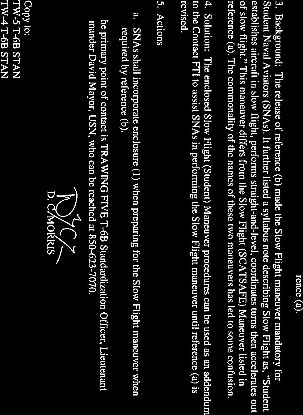
15 CHAPTER FIVE CHANGE 5 e. Energy Planning. Constant awareness of total energy state aides in correct maneuver selection and effective profile management, which allows a smooth flow between maneuvers with minimum delay SLOW FLIGHT (STUDENT) MANEUVER 1. Description. The slow flight maneuver is designed to develop your ability to fly the aircraft in a near-stalled condition. 2. General. Every takeoff and landing you make requires you to operate the aircraft at low airspeed. During training, students are taught "flight at minimum controllable airspeed" so they may learn the effect that airspeed has on aircraft performance and controllability. 3. Procedures. a. CONFIGURATION: At a safe altitude (complete maneuver above 6,000 feet AGL), slow the aircraft below 150 KIAS and configure with the landing gear down. b. CHECKLIST: Perform the Before Landing Checklist and the Pre-Stalling, Spinning, and Aerobatic Checklist over the ICS. c. CLEAR AREA: Clear working area with visual scan, TCAS, and clearing turns as required. d. Lower landing (LDG) flaps. Continue reducing airspeed to approximately 85 KIAS, while setting approximately 45% torque. e. Complete a coordinated, level 30 degree AOB turn for 180 degrees of heading followed by another 30 degree AOB turn in the opposite direction for 180 degrees back to original heading. Add power and trim as required to maintain altitude and airspeed. f. Advance power to maximum, check airspeed below 150 KIAS, raise the gear and move the flaps from LDG to TO, once airspeed is 110 KIAS minimum, retract the flaps. Report over ICS, Gear up, flaps up at knots. Trim for acceleration. g. Accelerate to normal cruise. As airspeed approaches 200KIAS, reduce power to ~54%. h. Re-trim as necessary to remove control pressures, check the balance ball is centered. NOTE The stick shaker may be on throughout the maneuver FLIGHT PROCEDURES
16 CHANGE 5 CHAPTER FIVE 517. SLOW FLIGHT (SCATSAFE) MANEUVER 1. Description. The SCATSAFE maneuver is designed to demonstrate various performance characteristics of the aircraft when in a near-stalled condition. 2. General. This maneuver will be demonstrated by the instructor. Every takeoff and landing you make requires you to operate the aircraft at low airspeed. During training, students are taught "flight at minimum controllable airspeed" so they may learn the effect that airspeed has on aircraft performance and controllability 3. Procedures. a. CONFIGURATION: At a safe altitude (complete maneuver above 6,000 feet AGL), slow the aircraft below 150 KIAS and configure with the landing gear down. b. CHECKLIST: Perform the Before Landing Checklist and the Pre-Stalling, Spinning, and Aerobatic Checklist over the ICS. c. CLEAR AREA: Clear working area with visual scan, TCAS, and clearing turns as required. d. Lower landing (LDG) flaps. Continue reducing airspeed to approximately 80 KIAS (15 units AOA), while setting approximately 45% torque. NOTE The stick shaker may be on throughout the demo. Demonstrate the following aircraft flight characteristics: S - Straight and Level. During operation on the back side of the power curve, increased AOA results in increased drag and a stall if not carefully flown. Note the pitch attitude, torque, and rudder deflection required to maintain straight-and-level flight. This is the sight picture a pilot should see at rotation during takeoff or just prior to touchdown during landing. C - Coordination Exercise. Conduct a series of left and right turns, using angle of bank. Keep the ball centered using coordinated rudder. Approximately two inches of right rudder is required to maintain straight-and-level, coordinated flight. Right turns require approximately twice the rudder deflection to maintain coordination. Left turns require approximately one-half inch of right rudder to maintain coordination. A - Adverse Yaw. Lack of coordinated rudder during a turn results in weaving or S-ing on final. Select two points, one directly in front of the aircraft and one approximately 20 to the right of the nose. Without applying rudder, initiate a rapid right turn with 20 bank. Note the initial tendency of the nose to yaw left. After approximately 20 of turn, roll out rapidly without using rudder. The nose continues past the selected roll out point then comes back. Next, initiate FLIGHT PROCEDURES 5-23
17 CHAPTER FIVE CHANGE 5 a right turn, using coordinated rudder. Notice that the nose immediately tracks in a coordinated manner. After 20 of turn, roll out using properly coordinated rudder and note that the nose stops on the selected rollout point. T - Torque and Turns. The T-6B initially tends to pitch up, yaw, and roll left if positive control is not maintained during full power takeoffs and landings. To demonstrate this, quickly increase power to MAX from straight-and-level, coordinated slow-flight and release the controls. The nose tracks up, yaws, and rolls left, and approaches a stall. Recover from the buffet, prior to stall. Reestablish slow-flight and increase power to MAX again. This time, hold proper takeoff pitch and apply coordinated rudder to maintain a proper nose track. Positive control of the aircraft ensures safe takeoffs, touch-and-go landings, and go-arounds. S - Steep Turns. High angles of bank at slow airspeeds increase stall speed and cause rapid turn rates. Slowly increase bank towards 60 while adding power and back pressure to maintain level flight. Look at a point on the ground and watch the wingtip appear to pivot around the selected point. The AOA quickly increases, progressing into a stall. Roll out of the bank to recover from the impending stall. A - Abrupt Control Movement. Fixation on the aim point during landing can cause an abrupt flare. Late recognition of the rapidly approaching runway causes the pilot to abruptly raise the nose of the aircraft, causing an approach-to-stall condition, a hard landing, or both. The stick shaker activates, but there is no decrease in sink rate. To demonstrate this, abruptly apply backstick pressure to 20 nose-high to simulate snatching the control stick in the flare. The AOA rapidly increases and the aircraft progresses towards a full stall. Release backpressure to recover. To avoid this condition on landing, view the total landing environment and apply controls in a smooth, positive manner. F - Flap Retraction. Flap retraction prior to the recommended airspeeds causes the aircraft to lose lift and develop a sink rate. From straight-and-level coordinated slow-flight, raise the flaps from LDG to UP without pausing at the TO position. While retracting the flaps, increase the pitch attitude to maintain altitude. Initially airspeed increases (due to reduced drag as flaps begin to retract), but as flaps retract towards UP, the AOA increases and a stall results. Recover from the stall by selecting LDG flaps. E - Effectiveness of Controls. Rapid control inputs, especially in the flare, often do not give the aircraft sufficient time to respond. Move the ailerons with small, rapid movements. Notice that even with aileron movement, there is little effect on heading or bank during slow-flight. In slowflight, smooth, positive inputs are required to effectively control the aircraft as there is less airflow over the control surfaces at slow airspeeds. 4. Common Errors. a. Abrupt control movements. b. Failure to clear area during maneuver FLIGHT PROCEDURES
18 CHANGE 5 CHAPTER FIVE c. Failure to maintain altitude. d. Failure to use adequate trim POWER-ON-STALLS 1. Description. Stall the aircraft in a power-on condition to demonstrate the proper recovery when power is available. 2. General. Proper recognition and recovery of an aerodynamic stall with minimum loss of altitude. Aircraft pitch and bank angle will be held constant until control effectiveness is lost, indicated by uncommanded nose drop or unplanned rolling motion. To recover, RELAX backstick pressure to break the stall, and select MAX power. Simultaneously LEVEL the wings and center the BALL. The maneuver is complete when the aircraft has established a positive rate of climb. An entry speed of 150 KIAS results in about feet altitude gain. 3. Procedures. a. CONFIGURATION: Establish the aircraft in the clean configuration. Complete maneuver above 6,000 feet AGL. b. CHECKLIST: Perform the Pre-Stalling, Spinning, and Aerobatic Checks. c. CLEAR AREA: Clear working area with visual scan, TCAS, and clearing turns as required. d. Straight-Ahead Stall. Adjust the PCL to 30-60% torque. Raise the nose to a pitch attitude between e. Maintain attitude using increasing back pressure. Keep the wings level with coordinated rudder and aileron. Initiate recovery when control effectiveness is lost. An uncommanded nose drop despite increased backpressure or an uncommanded rolling motion indicates loss of control effectiveness. Do not attempt to maintain pitch attitude or bank angle after control effectiveness is lost. Full back-stick may not occur before recovery is required. Emphasize observation of aircraft handling characteristics during recovery from the stall and not the exact point where the full stall is reached. f. Recovery. Simultaneously RELAX back-stick forces as necessary to break the stall, advance the PCL to MAX, use coordinated rudder and aileron to LEVEL the wings, and center the BALL. Avoid excessive or abrupt rudder movements during recovery phase. As AOA decreases and stall is broken, positive pressure is felt in the controls. At lower pitch attitudes (between 15 and 30 ), the aircraft stalls at a higher airspeed and regains flying airspeed faster. At higher pitch attitudes (between 30 and 40 ), the stall speed is slower and a greater pitch reduction is necessary to regain flying airspeed. FLIGHT PROCEDURES 5-25
19 CHAPTER FIVE CHANGE 5 g. Use maximum AOA to minimize altitude loss ( units AOA). Avoid a secondary stall (indicated by upward nose track stopping despite increasing back pressure on the control stick). A secondary stall is an accelerated stall that occurs after a partial recovery from a preceding stall. It is caused by attempting to hasten a stall recovery when the aircraft has not regained sufficient flying speed. Recovery is complete when the aircraft is wings level with a positive rate of climb. h. Turning Stall. Setup is the same as the straight-ahead stall, except of bank in either direction is added. Hold the bank angle with rudder and aileron pressure until control effectiveness is lost. Recovery is the same as for the straight-ahead stall. A precision entry is not as important as proper recognition and recovery from the stall. 4. Common Errors. a. Failure to maintain a constant pitch or bank attitude prior to loss of control effectiveness. b. Failure to recognize loss of control effectiveness (early/late initiation of recovery). c. Failure to recognize when the stall has been broken (early/late initiation of recovery to level flight). d. Failure to minimize altitude loss during recovery. Recovering with less than units AOA. e. Entering a secondary stall during the recovery POWER-OFF STALL (ELP STALL) 1. Description. Stall the aircraft in a power-off condition to demonstrate the proper recovery when no power is available. 2. General. Power off stalls are flown to practice recovery from potentially dangerous low airspeed conditions prior to high key and during the ELP. Power off stalls could occur, for example, during a dead engine glide to high key when the pilot gets distracted and fails to maintain proper flying speed. Speed may decrease for various reasons, including inattention, task saturation, and attempts to stretch the glide to regain profile. Before starting this maneuver, ensure you have plenty of airspace below you, as you will lose at least 1500 feet during the recovery, and will probably lose another while setting up your dead engine glide. Best glide speed in the clean configuration is approximately 125 KIAS with a sink rate of 1350 to 1500 feet per minute. Pay close attention to the nose attitude and flight characteristics of the airplane when flying the power-off, best glide speed. After the recovery, you will return to this attitude and airspeed to complete the maneuver FLIGHT PROCEDURES
20 CHANGE 5 CHAPTER FIVE 3. Procedures. a. CONFIGURATION: Establish the aircraft in the clean configuration. Begin the maneuver at slow cruise (150 kts), or airspeed at the IP s discretion. Complete the maneuver above 6,000 feet AGL. b. CHECKLIST: Perform the Pre-Stalling, Spinning, and Aerobatic Checks. c. CLEAR AREA: Clear working area with visual scan, TCAS, and clearing turns as required.. d. Roll wings level. If at or below 150 KIAS, reduce power to 4-6% torque and begin decelerating towards best glide speed, 125 KIAS. If above 150 KIAS, reduce power to 4-6% torque and zoom glide to capture best glide speed, 125 KIAS. e. As airspeed approaches 125 KIAS, lower nose to the 125-knot glide attitude (horizon bisecting windscreen). Crosscheck VSI for feet per minute sink rate. Re-trim and stabilize. f. Simulate High Key and lower the landing gear; Re-trim for 120-knot glide and commence a 15-20º AOB turn to Low Key. Complete the Before Landing Checklist. g. Raise the nose to 5-10º nose high and allow airspeed to decay until the first indication of impending stall (airframe buffet or stick shaker). h. Maintain the turn or profile groud track and recover by lowering the pitch attitude to put the prop arc on the horizon (~8º nose low) until 120 KIAS is regained. Altitude loss is approximately 800 feet. 4. Common Errors. a. Failure to recognize an approach to stall indication. b. Lowering the nose too far, resulting in excessive loss of altitude. c. Failure to properly capture airspeed LANDING PATTERN (APPROACH TURN) STALL 1. Description. Proper recognition of and recovery from approach to stall conditions in the landing pattern. Training emphasis is on recognition of approach-to-stall indications and appropriate recovery procedures. However, much like power-on stalls, the smoother the entry, the cleaner the stall. 2. General. In the landing pattern, unrecoverable stall or sink rate situations can occur before indications become obvious. If a stall indication occurs in the landing pattern, disregard ground FLIGHT PROCEDURES 5-27
21 CHAPTER FIVE CHANGE 5 track, and recover as described below. If in the pattern, do not hesitate to eject if recovery appears unlikely. Landing pattern (Approach Turn) stalls may be practiced in either direction and in any flap configuration. 3. Procedures. Landing Pattern (Approach Turn) Stall a. CONFIGURATION: Establish the aircraft in the appropriate downwind configuration (120 KIAS gear down, flaps as required). b. CHECKLIST: Perform the Pre-Stalling, Spinning, and Aerobatic Checklist and the Before Landing Checklist. c. CLEAR AREA: Clear working area with visual scan, TCAS, and clearing turns as required. d. Simulate the transition near the abeam position IAW Contact FTI landing pattern procedures. Power should be approximately 14/15/18% torque respectively, airspeed 120/115/110 KIAS, trimmed in a descending 30 o AOB turn to simulate the approach turn to final. e. Once stabilized on airspeed 120/115/110 KIAS in the simulated approach turn, raise the nose to 5-10 degrees nose high, and then reduce power to idle. Adjust ailerons to maintain AOB between degrees, and increase back stick pressure to hold the pitch attitude. f. At first indication of stall, stick shaker or airframe buffet, recover with minimal altitude loss. Landing Attitude Stall a. CONFIGURATION: Establish a simulated final approach at 5 to 10 knots above final approach airspeed commensurate with flap setting. b. CHECKLIST: Perform the Pre-Stalling, Spinning, and Aerobatic Checklist and the Before Landing Checklist. c. CLEAR AREA: Clear working area with visual scan, TCAS, and clearing turns as required. d. Retard the PCL to idle and execute a simulated landing transition. Hold the landing attitude constant until an approach to stall indication occurs. Recover on approach to stall indication, which is activation of the stick shaker or aircraft buffet, whichever occurs first. Recovery is similar to the Landing Pattern (Approach Turn) Stall FLIGHT PROCEDURES
22 CHANGE 5 CHAPTER FIVE Recovery For all Landing Pattern (Approach Turn) stalls, recover at approach to stall indication; either activation of the stick shaker or aircraft buffet, whichever occurs first. Do not enter a full stall! Use RELAX, MAX, LEVEL, BALL to recover. a. RELAX. Relax back-stick pressure slightly to decrease AOA and break the stall (do not dump the nose). b. MAX. Power to MAX. c. LEVEL. Level the wings to the horizon, and then establish a positive climbing attitude. Use units AOA for maximum performance. d. BALL. Apply right rudder as necessary to center the balance ball. Recovery is complete when the aircraft is wings level and safely climbing. 4. Common Errors SLIP a. Failure to maintain angle of bank during the entry. The aircraft will have a tendency to continue rolling past 30º to 45 angle of bank. In addition, with increasing angle of bank, the nose will have a tendency to drop. b. Releasing instead of relaxing back-stick pressure, or applying forward stick pressure on recovery, thus resulting in a nose low attitude and excessive altitude loss. c. Not relaxing back-stick pressure enough, causing the aircraft to remain stalled. d. Cycling rudders in an attempt to keep the ball centered before flying speed is attained. e. Delay in raising the nose to the recovery attitude to stop the altitude loss. f. Failure to add sufficient power on recovery. 1. Description. A slip is an out-of-balance flight condition used to increase the sink rate and lose excess altitude while maintaining a constant airspeed and a specific track over the ground. 2. General. A slip occurs when the aircraft slides sideways towards the center of the turn. It is caused by an insufficient amount of rudder in relation to the amount of aileron and the angle of bank used. If you roll into a turn without using coordinated rudder and aileron, or if you hold rudder against the turn after it has been established, the aircraft will slide sideways towards the center of the turn. A slip may also occur in straight-and-level flight if one wing is allowed to drag; that is, flying with one wing low, and holding the nose of the aircraft straight by the use of rudder pressure. In this case, the aircraft slips downward towards the earth s surface and loses FLIGHT PROCEDURES 5-29
23 COMTRAWINGFIVEINST W b. Maintenance procedures that require deviation from normal procedures shall be coordinated with North Tower prior to takeoff. (i.e. Unrestricted climbs to High-Key.) WARNING: Tower will not clear aircraft to take-off or land until maintenance aircraft reports operations normal at High-Key. 3.5 PRACTICE ABORTED TAKE-OFF DEMONSTRATIONS. a. Aircraft should request permission for the practice abort demonstration from North Ground during the initial taxi request or upon clearing the runway after a full-stop landing. b. At the hold short line at the runway approach end call: North Tower, (call sign) practice abort. c. After the demonstration is complete and the aircraft has returned to a safe taxi speed, aircraft may exit at mid-field. 3.6 DEPARTURE PROCEDURES VFR. a. Over upwind numbers turn in the shortest direction to the climb-out heading. The climb-out headings are: (1) Runway 05/ (2) Runway 23/ b. Do not penetrate South Whiting airspace without approval from tower. Langley Road is the airspace dividing line. c. Level off at MSL and accelerate until visually clear of the traffic pattern. NOTE: Reference (a) grants exception for exceeding 200 KIAS when operations that cannot safely be conducted at airspeeds less than 200 KIAS. Maintaining maximum power on climb-out affords aircrew the best opportunity for survival in the event of an emergency. d. When visually clear of traffic pattern, switch to Pensacola Departure Control ( UHF/CH 6), transition to a climb, and contact Pensacola Departure. Advise Pensacola Departure if deviations are necessary to avoid traffic or clouds. Climb airspeed is 180 KIAS. Pensacola Departure, (call sign), passing (altitude). NOTE: ATC will provide VFR departures clearance to turn on course and for higher altitudes above 4,500 MSL. e. All departures, VFR and IFR, from Runways 23 and 32 must be 2,700 MSL or higher by 6.5 DME. 3-6
24 COMTRAWINGFIVEINST W f. Transition to working and departure areas as described below: (1) North MOA Comply with ATC instructions. (See 4.2.1) (2) South MOA Comply with ATC instructions. (See 4.4.1) (3) Area 1/VFR West Departure - Climb VFR on departure heading for the runway in use and climb to 4,500 MSL. When instructed by ATC to climb to requested altitude, continue the climb to 6,500 MSL. When instructed by ATC to proceed on course or when leaving 4,200 MSL, whichever occurs first, turn to a heading of 270. Expect to switch to Pensacola Departure West ( UHF/CH 11). NOTE: When transiting to Area 1, be aware of helicopter traffic transiting at or below 5,000 MSL north of I-10, commercial traffic descending in-bound to KPNS from the northwest, and T-6B traffic working the I-10 section line in Area 1. WARNING: Area 1 traffic be advised of multiple antennas (antenna farm) located along I-10 up to 2,049 MSL. (4) Fox Area (Northwest) - Climb VFR on departure heading for the runway in use and begin a climb to 4,500 MSL. When instructed by ATC to Proceed on course or when leaving 4,200 MSL, whichever occurs first, turn to a heading between (5) Pelican Area/VFR North or East Departure - Climb VFR on departure heading for the runway in use and begin a climb to 4,500 MSL. When instructed by ATC to climb to requested altitude, continue the climb to 5,500 MSL. When instructed by ATC to proceed on course or when leaving 4,200 MSL, whichever occurs first, turn to a heading of 360. (6) Area 3/South Departure Climb VFR on departure heading for the runway in use and begin a climb to 4,500 MSL. Maintain climb out heading and 4,500 MSL until Pensacola Departure clears to 180. Expect a further climb with ATC. Expect a switch to Pensacola Departure Southeast ( UHF/CH 7). Maintain radar advisories while operating in Area 3. g. North and South MOA: Continue as directed by ATC. Once established in the MOA, switch to MOA discrete. h. North, West and Fox Departures: Continue on appropriate departure heading and altitude until reaching the departure s termination point for VFR advisories, then report: Pensacola Departure, (call sign), clear to the North/West/Northwest. i. All aircraft departing VFR shall maintain radar advisories until reaching the following termination points: 3-7
25 COMTRAWINGFIVEINST W (1) North Departure (Pelican Area/VFR to the North/VFR to the East) Crossing Highway 4. (NSE 12 DME). (2) South Departure (Area 3/VFR to the South) Crossing I-10. If conducting aerobatics or OCF in Area 3, maintain assigned squawk when crossing I-10 for VFR flight following. Do not call clear to the south or cancel radar advisories. Radios should be tuned to Area 3 Common (299.5 UHF/CH 16) and Pensacola Approach (119.0 VHF/CH 7 or VHF CH/57) as directed for simultaneous monitoring of advisories. (3) West Departure (Area 1/VFR to the West) Abeam the north/south railroad tracks in the vicinity of Bay Springs (Point ENSLY - NSE 24 DME). If proceeding to Area 1, maintain 6,500 MSL until South of the lateral confines of the V198/V241 (northern boundary of the South MOA). (4) Fox Departure Crossing the southern boundary of the Pelican (North of the lateral confines of V198/V241), but no later than HWY 29(NSE 17 DME). j. Upon reaching the termination point for VFR traffic advisories and/or when directed by ATC, switch to the appropriate area common frequency, squawk 1200 or 4700 as appropriate, and proceed to the working area. Course Rules Departures (RWY 5/14) Figure
26 COMTRAWINGFIVEINST W IFR/IMC DEPARTURES. Course Rules Departures (RWY 23/32) Figure 3-5 NOTE: When field is operating VFR, maintain MSL until clear of the traffic pattern. a. Stereo Flight Plans/VFR-on-Top Departure. VFR-On-Top (OTP) (NSE-3 stereo route) procedures are for the purpose of receiving IFR departure service until in VMC conditions. (1) The full NSE-3 VFR-On-Top clearance will be: (Call sign) cleared to the MERTY intersection via radar vectors. Climb to and report reaching VFR conditions on top. If not on top at 4,000, maintain 4,000 and advise, departure frequency 278.8, squawk ####. (If VFR prior to 4,000, cancel IFR). (2) The NSE-3 clearance may be issued in short form as follows: (Call sign) cleared to the MERTY intersection via NSE-3, squawk ####. NOTE: Pilot acknowledgment of the short NSE-3 clearance constitutes acceptance of the full clearance. (3) Aircraft shall not depart the run up areas until IFR clearance has been received. 3-9
27 COMTRAWINGFIVEINST W b. Precision Minimums. When weather at North Field is below non-precision minimums, aircraft may depart North Field only with one of the following: (1) KNSE ILS Runway 14 is operational, weather is at or above KNSE 14 ILS minimums and KNSE Runway 14 is in use. or (2) If the ILS is not operational or not available: South Whiting (KNDZ) GCA is operational to the runway in use, restricted airspace is available, weather is at or above KNDZ GCA minimums. Check KNDZ NOTAMS or contact NAS Whiting Field Base Ops ( ) to confirm the GCA is available. 3.7 LATERAL DEPARTURES. a. Lateral departures are departures through the Class C Airspace at an altitude other than normal course rules departure. When possible, requests should initially be made through Ground Control prior to takeoff and again with Pensacola Departure Control upon departure. Pensacola Departure, (call sign), passing (altitude), request lateral departure to (area or direction) at (requested altitude). b. If the request is approved, maintain radar advisories (flight following) with ATC until clear of the local airspace. Pensacola Departure, (call sign), clear to the (cardinal direction), terminate. WARNING: When executing a lateral departure to the north, be particularly aware of traffic inbound, on the course rules, in the vicinity of Point Nugget. 3.8 NORTH FIELD ARRIVAL DAY VFR. a. Delays. If for any reason a delay should occur (runway change, etc.) that will keep an aircraft from proceeding past a reporting point, Pensacola Approach Control will advise the length of expected delay and request pilot intentions. Pilots may elect to enter a right hand, VFR holding pattern at the reporting point at 150 KIAS. If traffic warrants, Approach Control may recommend a holding altitude, which will provide separation between aircraft. Solo aircraft unable to maintain VMC should return to a NOLF or declare an emergency. b. VMC Weather Deviations. Should weather necessitate deviation from course rules, pilots shall first advise TRACON of intentions. If weather conditions preclude aircraft from adhering to specified altitudes, pilots shall select an altitude stated below to maintain VMC: 3-10
28 Ejection Seat Sequencing Mitigation Procedures Dual Flights ISS Mode Selector SOLO in flight (Before Takeoff checks) RCP occupant shall initiate ejection ON third EJECT call FCP occupant shall initiate ejection NET ~0.5 sec AFTER third EJECT call Solo Flights Normal NATOPS Procedures Apply Ensure ISS Mode Selector is in SOLO CRM RCP Delaying Ejection May lead to collision with FCP seat RCP shall not hesitate or delay ejecting RCP occupant shall initiate ejection ON third EJECT call FCP Initiating Ejection Too Soon May lead to collision with RCP seat FCP shall initiate ejection NET ~0.5 sec after third EJECT call Contingencies FCP Incapacitation 1. ISS Mode Selector BOTH 2. RCP Eject ICS Failure Face curtain signal serves as the prepatory command during a controlled ejection. A thumbs up from each occupant is required to initiate ejection sequence. FCP shall initiate ejection sequence with three raps of the canopy RCP occupant shall initiate ejection ON third rap FCP occupant shall initiate ejection NET ~0.5 seconds AFTER third rap Misc Unqualified personnel prohibited Must be NATOPS qualified, enrolled in a formal aviation syllabus, or an observer qualified Naval Flight Officer, Flight Surgeon, or Aeromedical Safety Officer Delaying ejection below 2,000 ft AGL is not recommended Any delays may negatively impact the ejection envelope FCP occupant initiates ejection NET ~0.5 sec AFTER third EJECT call or immediately after confirming the RCP occupant has ejected Proper manual ejection sequencing requires the RCP occupant to eject prior to the FCP occupant

29

30
31
NORMAL TAKEOFF AND CLIMB
 NORMAL TAKEOFF AND CLIMB CROSSWIND TAKEOFF AND CLIMB The normal takeoff is one in which the airplane is headed directly into the wind or the wind is very light, and the takeoff surface is firm with no
CIVIL AIR PATROL United States Air Force Auxiliary Cadet Program Directorate. Cessna 172 Maneuvers and Procedures
 CIVIL AIR PATROL United States Air Force Auxiliary Cadet Program Directorate Cessna 172 Maneuvers and Procedures This study guide is designed for the National Flight Academy Ground School. The information
I2102 WORKSHEET. Planned Route: Takeoff: KNSE, RWY 32 Altitude: 12,000 Route: RADAR DEPARTURE. Syllabus Notes None. Special Syllabus Requirements None
 Planned Route: Takeoff: KNSE, RWY 32 Altitude: 12,000 Route: RADAR DEPARTURE Syllabus Notes None Special Syllabus Requirements None I2102 WORKSHEET Discuss a. IMC Emergencies NATOPS statement on sound
PERFORMANCE MANEUVERS
 Ch 09.qxd 5/7/04 8:14 AM Page 9-1 PERFORMANCE MANEUVERS Performance maneuvers are used to develop a high degree of pilot skill. They aid the pilot in analyzing the forces acting on the airplane and in
XI.C. Power-Off Stalls
 References: FAA-H-8083-3; POH/AFM Objectives Key Elements Elements Schedule Equipment IP s Actions SP s Actions Completion Standards The student should develop knowledge of stalls regarding aerodynamics,
Tecnam Eaglet Standard Operating Procedures and Maneuvers Supplement
 Tecnam Eaglet Standard Operating Procedures and Maneuvers Supplement Normal Takeoff Flaps Take Off Trim set Fuel pump on Check for traffic Line up on white stripe Full power Stick should be located in
Visualized Flight Maneuvers Handbook
 Visualized Flight Maneuvers Handbook For High Wing Aircraft Third Edition For Instructors and Students Aviation Supplies & Academics, Inc. Newcastle, Washington Visualized Flight Maneuvers Handbook for
CESSNA 172-SP PRIVATE & COMMERCIAL COURSE
 CESSNA 172-SP PRIVATE & COMMERCIAL COURSE University of Dubuque INTENTIONALLY LEFT BLANK Revision 1 Standard Operating Procedures 1 CALLOUTS CONDITION Parking Brake Released After Takeoff Power has been
XI.B. Power-On Stalls
 XI.B. Power-On Stalls References: AC 61-67; FAA-H-8083-3; POH/AFM Objectives Key Elements Elements Schedule Equipment IP s Actions SP s Actions Completion Standards The student should develop knowledge
I2103 WORKSHEET. Planned Route: Takeoff: KNSE, RWY 32 Altitude: 12,000 Route: RADAR DEPARTURE. Syllabus Notes None
 Planned Route: Takeoff: KNSE, RWY 32 Altitude: 12,000 Route: RADAR DEPARTURE Syllabus Notes None I2103 WORKSHEET Special Syllabus Requirements Proceed direct to homefield using any available NAVAID. Discuss
See the diagrams at the end of this manual for judging position locations.
 Landing Events Penalties General Judges should use airport diagrams, satellite pictures or other means to determine, as accurately as possible, assessments of landing pattern penalties. Judges should be
PROCEDURES GUIDE CESSNA 172N SKYHAWK
 PROCEDURES GUIDE CESSNA 172N SKYHAWK THESE PROCEDURES ARE DESIGNED TO PROVIDE STANDARDIZED METHODS UNDER NORMAL CONDITIONS. AS CONDITIONS CHANGE, THE PROCEDURES WILL NEED TO BE ADJUSTED. PASSENGER BRIEFING
TAILWHEEL AIRPLANES LANDING GEAR TAXIING
 Ch 13.qxd 5/7/04 10:04 AM Page 13-1 TAILWHEEL AIRPLANES Tailwheel airplanes are often referred to as conventional gear airplanes. Due to their design and structure, tailwheel airplanes exhibit operational
Single Engine Complex Training Supplement PA28R-201 Piper Arrow III (Spring 2016 Revision)
") Single Engine Complex Training Supplement PA28R-201 Piper Arrow III (Spring 2016 Revision) V-speed Quick Reference V-Speed KIAS Description Airspeed Indicator Marking VSO 55 Stall speed in landing configuration
Single Engine Complex Training Supplement PA28R-201 Piper Arrow III (Spring 2016 Revision) V-speed Quick Reference V-Speed KIAS Description Airspeed Indicator Marking VSO 55 Stall speed in landing configuration
PROCEDURES GUIDE. FLIGHT MANEUVERS for the SPORT PILOT
 Page 1 of 10 PROCEDURES GUIDE FLIGHT MANEUVERS for the SPORT PILOT * Author s Note: Whereas this procedures guide has been written for a specific application, it can easily be modified to fit many different
OFFICE HOURS Monday through Friday, 7:30 a.m. to 4:30 p.m., Pacific Time. Lunch hour is 11:30 a.m. to 12:30 p.m.
 Robinson Helicopter Company Phone: (310) 539-0508 2901 Airport Drive Fax: (310) 539-5198 Torrance, California 90505-6115 Web: www.robinsonheli.com United States of America OFFICE HOURS Monday through Friday,
Climbs, descents, turns, and stalls These are some of the maneuvers you'll practice, and practice, and practice By David Montoya
 Climbs, descents, turns, and stalls These are some of the maneuvers you'll practice, and practice, and practice By David Montoya Air work stalls, steep turns, climbs, descents, slow flight is the one element
OFFICE HOURS Monday through Friday, 7:30 a.m. to 4:30 p.m., Pacific Time. Lunch hour is 11:30 a.m. to 12:30 p.m.
 Robinson Helicopter Company Phone: (310) 539-0508 2901 Airport Drive Fax: (310) 539-5198 Torrance, California 90505-6115 Web: www.robinsonheli.com United States of America OFFICE HOURS Monday through Friday,
VFR Circuit Tutorial. A Hong Kong-based Virtual Airline. VOHK Training Team Version 2.1 Flight Simulation Use Only 9 July 2017
 A Hong Kong-based Virtual Airline VFR Circuit Tutorial VOHK Training Team Version 2.1 Flight Simulation Use Only 9 July 2017 Copyright 2017 Oasis Hong Kong Virtual Page 1 Oasis Hong Kong Virtual (VOHK)
CAP-USAF FLIGHT MANEUVERS GUIDE
 CAP-USAF FLIGHT MANEUVERS GUIDE February 2012 Flight Maneuvers Guide This guide describes and standardizes the instruction and performance of the various flight maneuvers described in Chapter 3 of AFI11-2CAP-USAF,
XI.D. Crossed-Control Stalls
 References: FAA-H-8083-3; POH/AFM Objectives Key Elements Elements Schedule Equipment IP s Actions SP s Actions Completion Standards The student should understand the dynamics of a crossed-control stall
Airplane Flying Handbook. Figure 6-4. Rectangular course.
 Airplane Flying Handbook Rectangular Course Figure 6-4. Rectangular course. Normally, the first ground reference maneuver the pilot is introduced to is the rectangular course. [Figure 6-4] The rectangular
NORMAL TAKEOFF PILOT TRAINING MANUAL KING AIR 200 SERIES OF AIRCRAFT
 NORMAL TAKEOFF Climb-Out 1. Accelerate to 160 KIAS 2. Landing/Taxi lights: Out 3. Climb Checklist complete 1. 160 KIAS up to 10,000 ft 2. Decrease 2 KIAS per 1,000 ft above 10,000 ft to 130 KIAS at 25,000
Cessna 152 Standardization Manual
 Cessna 152 Standardization Manual This manual is to be utilized in conjunction with the manufacturers approved POH/ AFM and the Airplane Flying Handbook (FAA-H-8083-3A). This manual should be used as a
VII.E. Normal and Crosswind Approach and Landing
 References: FAA-H-8083-3; POH/AFM Objectives Key Elements Elements Schedule Equipment IP s Actions SP s Actions Completion Standards The student should be able to perform a normal approach and landing
Gleim Private Pilot Flight Maneuvers Seventh Edition, 1st Printing Updates February 2018
 Page 1 of 11 Gleim Private Pilot Flight Maneuvers Seventh Edition, 1st Printing Updates February 2018 If you are tested on any content not represented in our materials or this update, please share this
Flight Profiles are designed as a guideline. Power settings are recommended and subject to change based
 MANEUVERS AND PROCEDURES Flight Profiles are designed as a guideline. Power settings are recommended and subject to change based upon actual conditions (i.e. aircraft weight, pressure altitude, icing conditions,
Cessna 172S Skyhawk Standardization Manual
 Cessna 172S Skyhawk Standardization Manual This manual is to be utilized in conjunction with the manufacturers approved POH/ AFM and the Airplane Flying Handbook (FAA-H-8083-3A). This manual should be
Front Cover Picture Mark Rasmussen - Fotolia.com
 Flight Maneuvers And Stick and Rudder Skills A complete learn to fly handbook by one of aviation s most knowledgeable and experienced flight instructors Front Cover Picture Mark Rasmussen - Fotolia.com
Medium, Climbing and Descending Turns
 Basic Concepts Medium, Climbing and Descending Turns A medium turn is defined as a turn using up to 30 degrees angle of bank. Climbing and descending turns are combined with medium turns within this briefing,
X.A. Rectangular Course
 References: FAA-H-8083-3 Objectives Key Elements Elements Schedule Equipment IP s Actions SP s Actions Completion Standards The student should develop knowledge of the elements related to rectangular courses
Compiled by Matt Zagoren
 The information provided in this document is to be used during simulated flight only and is not intended to be used in real life. Attention VA's - you may post this file on your site for download. Please
MANEUVERS GUIDE. Liberty Aerospace 1383 General Aviation Drive Melbourne, FL (800)
") MANEUVERS GUIDE Liberty Aerospace 1383 General Aviation Drive Melbourne, FL 32935 (800) 759-5953 www.libertyaircraft.com Normal/Crosswind Takeoff and Climb 1. Complete the runup and before takeoff checklist.
MANEUVERS GUIDE Liberty Aerospace 1383 General Aviation Drive Melbourne, FL 32935 (800) 759-5953 www.libertyaircraft.com Normal/Crosswind Takeoff and Climb 1. Complete the runup and before takeoff checklist.
VI.B. Traffic Patterns
 References: FAA-H-8083-3; FAA-H-8083-25; AC 90-42; AC90-66; AIM Objectives Key Elements Elements Schedule Equipment IP s Actions SP s Actions Completion Standards The student should develop knowledge of
Piper PA Seminole 1. Standardization Manual
 Piper PA-44-180 Seminole Standardization Manual This manual is to be utilized in conjunction with the manufacturers approved POH/AFM and the Airplane Flying Handbook (FAA-H-8083-3A). This manual should
C-130 Reduction in Directional Stability at Low Dynamic Pressure and High Power Settings
 C-130 Reduction in Directional Stability at Low Dynamic Pressure and High Power Settings The C-130 experiences a marked reduction of directional stability at low dynamic pressures, high power settings,
Normal T/O Procedure. Short Field T/O Procedure
 Normal T/O Procedure Add full power: Engine Instruments green Airspeed alive 1,000 AGL Accelerate to enroute climb 85 KIAS Complete climb check Vr = 55-60 Vy 79 KIAS Prior to Receiving T/O Clearance Complete
VII.H. Go-Around/Rejected Landing
 VII.H. Go-Around/Rejected Landing References: FAA-H-8083-3; POH/AFM Objectives Key Elements Elements Schedule Equipment IP s Actions SP s Actions Completion Standards The student should develop knowledge
FLIGHT AT MINIMUM CONTROLLABLE AIRSPEED
 INTRODUCTION The maintenance of lift and control of an airplane in flight requires a certain minimum airspeed. This critical airspeed depends on certain factors, such as gross weight, load factors, and
XII.A-D. Basic Attitude Instrument Flight
 References: FAA-H-8083-3; FAA-8083-3-15 Objectives Key Elements Elements Schedule Equipment IP s Actions SP s Actions Completion Standards The student should develop knowledge of the elements related to
Beechcraft Duchess 76 Maneuver Notes
 Beechcraft Duchess 76 Maneuver Notes I. Maneuver notes for Performance (AOA V), Slow Flight and Stalls (AOA VIII), Emergency Operations (AOA X), and Multiengine Operations (AOA XI) a. Maneuvers addressed:
FAA-S-ACS-6 June 2016 Private Pilot Airplane Airman Certification Standards. Task ACS Settings
 FAA-S-ACS-6 June 2016 Private Pilot Airplane Airman Certification Standards Cessna 172: mixture rich, carb heat out if below the green arc. Clearing Turns all manuevers! Task ACS Settings Traffic Pattern
VI.A-E. Basic Attitude Instrument Flight
 References: FAA-H-8083-3; FAA-8083-3-15 Objectives Key Elements Elements Schedule Equipment IP s Actions SP s Actions Completion Standards The student should develop knowledge of the elements related to
TERMS AND DEFINITIONS
 Ch 05.qxd 5/7/04 7:02 AM Page 5-1 GENERAL This chapter discusses takeoffs and departure climbs in tricycle landing gear (nosewheel-type) airplanes under normal conditions, and under conditions which require
II.E. Airplane Flight Controls
 References: FAA-H-8083-3; FAA-8083-3-25 Objectives Key Elements Elements Schedule Equipment IP s Actions SP s Actions Completion Standards The student should develop knowledge of the elements related to
Cessna 172R Profiles
 Cessna 172R Profiles TRAFFIC PATTERNS (Verify pattern altitude) Start your first climbing turn within 300' of pattern altitude Enter 45 degree angle to the downwind leg Depart the traffic pattern straight-out,
CHAPTER 8 MANEUVERS TABLE OF CONTENTS
 CHAPTER 8 MANEUVERS TABLE OF CONTENTS Transition Airspeeds... 3 Checklists and callouts during maneuvers... 3 Guidance to better maneuver execution... 3 Taxiing... 5 Pre-Maneuver Checklist... 6 Clearing
Jabiru J230-SP Section 10
 Jabiru J230-SP Section 10 Section 10 10.1 Introduction This section contains information on the basic flight controls, door operation, and entry and egress, followed by a flight training outline compiled
Advanced Stalling. L = CL ½ ρ V 2 S. L = angle of attack x airspeed. h L = angle of attack x h airspeed. Advanced Manoeuvres
 Advanced Manoeuvres Advanced Stalling This Advanced Stalling lesson covers the factors that affect the observed airspeed and nose attitude at the stall. Although the aeroplane always stalls when the aerofoil
Commercial Maneuvers for PA28RT-201
 Commercial Maneuvers for PA28RT-201 Cruise checklist: Power 23'', 2400 RPM (23, 24) Lean mixture Fuel Pump Off (Check positive fuel pressure) Landing light Off Pre-Maneuver Checklist in the Takeoff configuration
Straight and Level. Basic Concepts. Figure 1
 Basic Concepts Straight and Level This lesson should start with you asking the student what they did in the last lesson, what do they remember, and determining if they have remembered correctly. We must
VIII.A. Straight and Level Flight
 VIII.A. Straight and Level Flight References: FAA-H-8083-3; FAA-H-8083-25 Objectives Key Elements Elements Schedule Equipment IP s Actions SP s Actions Completion Standards The student should develop the
Discuss: 1. Instrument Flight Checklist
 INST 1 Prerequisites: 1. OFT: Tac 1 2. CBT: Basic Instrument Flight, IFR Navigation I & II Lessons P2 501, P2 502, & P2 503. Discuss: 1. Instrument Flight Checklist NATOPS 13.1.3 Instrument Flight Checklist
C-182P MANEUVERS GUIDE TABLE OF CONTENTS
 INTRODUCTION The following maneuver guide is designed to provide a technique for completing each VFR maneuver required by the FAA s Practical Test Standards for the Private Practical Test. By performing
VIII.A. Straight and Level Flight
 VIII.A. Straight and Level Flight References: FAA-H-8083-3; FAA-H-8083-25 Objectives Key Elements Elements Schedule Equipment IP s Actions SP s Actions Completion Standards The student should develop the
Guidance Notes PRIVATE AND COMMERCIAL PILOT TRAINING
 PRIVATE AND COMMERCIAL PILOT TRAINING September 2005 1 st Edition ACKNOWLEDGEMENT Transport Canada thanks the Federal Aviation Administration of the United States for their permission to use the chapter
IV. AREA OF OPERATION: TAKEOFFS, LANDINGS, AND GO AROUNDS A. TASK: NORMAL AND CROSSWIND TAKEOFF AND CLIMB
 IV. AREA OF OPERATION: TAKEOFFS, LANDINGS, AND GO AROUNDS A. TASK: NORMAL AND CROSSWIND TAKEOFF AND CLIMB FAA-H-8083-3; POH/AFM NOTE: If a crosswind condition does not exist, the applicant's knowledge
Circuit Considerations
 Circuit Training Circuit Considerations This briefing deals with those aspects of a normal circuit that were deferred during Circuit Introduction, to avoid student overload. Objectives To continue circuit
X.B. S-Turns. References: FAA-H The student should develop knowledge of the elements related to S-turns as necessary in the Private Pilot PTS.
 References: FAA-H-8083-3 Objectives Key Elements Elements Schedule Equipment IP s Actions SP s Actions Completion Standards The student should develop knowledge of the elements related to S-turns as necessary
FFI Formation Guidelines and Standard Procedures Mooney Supplement (28 Dec, 2018; Rev 12)
") FFI Formation Guidelines and Standard Procedures Mooney Supplement (28 Dec, 2018; Rev 12) This document describes formation flight differences between RV and Mooney aircraft. In conjunction with the FFI
FFI Formation Guidelines and Standard Procedures Mooney Supplement (28 Dec, 2018; Rev 12) This document describes formation flight differences between RV and Mooney aircraft. In conjunction with the FFI
C-182P MANEUVERS GUIDE TABLE OF CONTENTS
 INTRODUCTION The following maneuver guide is designed to provide a technique for completing each VFR maneuver required by the FAA s Practical Test Standards for the Private Practical Test. By performing
Cessna 172 Profiles. TRAFFIC PATTERNS (Check Chart Supplement prior to flight) Index
 Index") Cessna 172 Profiles TRAFFIC PATTERNS (Check Chart Supplement prior to flight) Index When Cleared for Takeoff - Landing/Taxi lights ON Mixture-As Required Power-Check Takeoff RPM Power Climb at Vy Start
Cessna 172 Profiles TRAFFIC PATTERNS (Check Chart Supplement prior to flight) Index When Cleared for Takeoff - Landing/Taxi lights ON Mixture-As Required Power-Check Takeoff RPM Power Climb at Vy Start
PRIVATE PILOT MANEUVERS Practical Test Standards FAA-S A
 PRIVATE PILOT MANEUVERS Practical Test Standards FAA-S-8081-15A Special Emphasis Areas Examiners shall place special emphasis upon areas of aircraft operation considered critical to flight safety. Among
IVAO International Virtual Aviation Organization Training department
 1 Introduction IVAO International Virtual Aviation Organization Training department TRAFFIC PATTERN DESCRIPTION An aerodrome traffic pattern is used by VFR traffic for training purpose or to prepare the
Aviation Merit Badge Knowledge Check
 Aviation Merit Badge Knowledge Check Name: Troop: Location: Test Score: Total: Each question is worth 2.5 points. 70% is passing Dan Beard Council Aviation Knowledge Check 1 Question 1: The upward acting
Circuit Introduction. Considerations. Circuit Training
 Circuit Training Circuit Introduction The circuit is an orderly pattern used to position the aeroplane for landing and minimise the risk of collision with other aircraft. Airfields attract aircraft, therefore
Things to remember when flying N102RE or any Taildragger
 Page 1 of 8 Things to remember when flying N102RE or any Taildragger 1. The Center of Gravity (CG) is behind the main between a taildragger (i.e. conventional gear airplane) and a tricycle gear airplane
Climbing and Descending
 Basic Concepts Climbing and Descending This lesson builds on the coordination skills learnt in the previous lesson, Straight and Level. Check with the student what the important elements of the last lesson
Q3102 Briefing Guide (Worksheet)
") T-6B JPPT 1542.165A Simulator Event Briefing Guide Q3102 Briefing Guide (Worksheet) Planned Route: Takeoff: KNSE, Rwy 32 MOA Limits Altitude: South MOA or North MOA Route: Training Device: OFT SYLLABUS
T-6B JPPT 1542.165A Simulator Event Briefing Guide Q3102 Briefing Guide (Worksheet) Planned Route: Takeoff: KNSE, Rwy 32 MOA Limits Altitude: South MOA or North MOA Route: Training Device: OFT SYLLABUS
Spin Training. Bob Wander Soaring Books & Supplies Website:
 Spin Training Bob Wander Soaring Books & Supplies Website: www.bobwander.com E-Mail: Soarbooks@aol.com This Presentation Is Based On A Chapter In: Why Is Spin Training Important? Spins have been with us
Andy Foster s CFI-S Flight Procedures (FLIP) Book
 Book") Andy Foster s CFI-S Flight Procedures (FLIP) Book Andy Foster s CFI-S FLIP Book Page 2 The FLIP Book The FLIP (Flight Procedures) Book is intended to be a handy reference for instructors and students when
Andy Foster s CFI-S Flight Procedures (FLIP) Book Andy Foster s CFI-S FLIP Book Page 2 The FLIP Book The FLIP (Flight Procedures) Book is intended to be a handy reference for instructors and students when
Noise Abatement Takeoff 1 Close In Profile
 PF Duties Captain: Advance thrust to 70% N1 (Allow Engines to stabilize) Noise Abatement Takeoff 1 Close In Profile Flaps Increase Speed to Vref 30 +80kts Climb Checklist Push N1 Button to set Takeoff
Sportsman (401) Maneuver Descriptions. And. Suggested Downgrades
 Maneuver Descriptions. And. Suggested Downgrades") Sportsman (401) Maneuver Descriptions And Suggested Downgrades 2015 Purpose: The purpose of this guide is to furnish an accurate description of each maneuver of the Sportsman (401) pattern sequence. Study
Sportsman (401) Maneuver Descriptions And Suggested Downgrades 2015 Purpose: The purpose of this guide is to furnish an accurate description of each maneuver of the Sportsman (401) pattern sequence. Study
VI.B. Traffic Patterns
 References: FAA-H-8083-3; FAA-H-8083-25; AC 90-42; AC90-66; AIM Objectives Key Elements Elements Schedule Equipment IP s Actions SP s Actions Completion Standards The student should develop knowledge of
Winnipeg Headingley Aero Modellers. Things About Airplanes.
 Winnipeg Headingley Aero Modellers Things About Airplanes. Table of Contents Introduction...2 The Airplane...2 How the Airplane is Controlled...3 How the Airplane Flies...6 Lift...6 Weight...8 Thrust...9
Cessna Aircraft Short & Soft Field Takeoff & Landing Techniques
 Cessna Aircraft Short & Soft Field Takeoff & Landing Techniques Introduce speaker. 1 Objectives / Content For short- and soft-field takeoff and landing operations in CAP Cessna aircraft, review: Standards
THE AIRCRAFT IN FLIGHT Issue /07/12
 1 INTRODUCTION This series of tutorials for the CIX VFR Club are based on real world training. Each document focuses on a small part only of the necessary skills required to fly a light aircraft, and by
Maximum Rate Turns. Objective To carry out a balanced, maximum rate, level turn using full power.
 Advanced Manoeuvres Maximum Rate Turns To achieve the maximum rate of turn, the greatest possible force toward the centre of the turn is required. This is achieved by inclining the lift vector as far as
G-BCKU Aerobatic Sequences
 G-BCKU Aerobatic Sequences Flight Manual Edition No. 1 REIMSjCESSNA FRA l50l November 1971 AEROBATIC MANEUVERS AEROBATIC-CONSIDERATIONS The FRAl50L is certificated in the Aerobatic Category for the maneuvers
Stalls and Spins. Tom Johnson CFIG
 Stalls and Spins Tom Johnson CFIG Contents Angle of Attack Stall Recognition and Recovery Spin Entry and Recovery Load Limit Considerations Gust Induced Stall and Spin Accidents Stalls a stall is a loss
Bonanza/Debonair Pilots
 Bonanza/Debonair Pilots Completing this worksheet is a great way to reinforce the proper speeds for operating your Bonanza or Debonair under varying operating conditions, and to understand the changes
Flying The. Traffic Pattern. Skill Level: Basic
 Flying The Now that you ve mastered a number of basic and intermediate flying skills, it s time to put them all to the test in the exercise that combines them all Flying The Traffic Pattern. In this Flight
April 4, Eye of Experience #12: Understanding the Stall
 April 4, 1999 Eye of Experience #12: Understanding the Stall Stall entry and recovery is one of the most discussed and cussed portions of a flight training syllabus. Yet, AVweb's Howard Fried believes
Pre Solo Written For Schweizer 2-33 Glider. Eagles Sport Aviation Club
 Pre Solo Written For Schweizer 2-33 Glider Eagles Sport Aviation Club Student Date: Instructor 1) What is the maximum gross weight for the 2-33? Empty Weight? 2) What position should the trim level be
Mountain Fury Mountain Search Flying Course Syllabus
 Mountain Fury Mountain Search Flying Course Syllabus Goals 1. Pilots who complete this program will be able to perform with precision and confidence all of the tasks and flight maneuvers required for safe
Accident Prevention Program
 Accident Prevention Program Wind Shear "Tonto 55, final controller, how do you read...?" "55, loud and clear." This has been a good flight thought the Instructor Pilot (IP) as the pilot in front smoothly
Lesson: Airspeed Control
 11/20/2018 Airspeed Control Page 1 Lesson: Airspeed Control Objectives: o Knowledge o An understanding of the aerodynamics related to airspeed control o Skill o The ability to establish and maintain a
Ottawa Remote Control Club Wings Program
 + Ottawa Remote Control Club Wings Program Guide line By Shahram Ghorashi Chief Flying Instructor Table of Contents Rule and regulation Quiz 3 Purpose of the program 4 Theory of flight Thrust 4 Drag 4
Low Flying Introduction
 Advanced Manoeuvres Low Flying Introduction Commonly, low flying refers to any flight at or below 500 feet agl that may be practised only in designated low flying zones. By maintaining good situational
NSRCA Club or Novice Class. Maneuver Descriptions. And. Suggested Downgrades
 NSRCA Club or Novice Class Maneuver Descriptions And Suggested Downgrades August 18, 2016 Purpose: The purpose of this guide is to furnish an accurate description of each maneuver of the NSRCA Club or
Gold Seal s Top Five Landing Mistakes
 Gold Seal s Top Five Landing Mistakes by Russell Still, MCFI Copyright 2017 by Atlanta Flight, Inc. Mistake #1 Excess Airspeed Almost all landing mistakes come from the same pool of pilot errors. Many
Maneuver Descriptions
 2017-2018 Senior Pattern Association Section III Maneuver Descriptions NOTE: MANEUVER DESCRIPTIONS THAT FOLLOW ARE TAKEN VERBATIM FROM THE APPROPRIATE AMA RULE BOOKS FROM WHICH THE MANEUVERS WERE TAKEN.
I2101 SIMULATOR ABBREVIATED CHECKLIST
 WORKSHEET I2101 SIMULATOR ABBREVIATED CHECKLIST Planned Route: Takeoff: KNSE, RWY 32 Altitude: 12,000 Route: PENSACOLA NORTH MOA Special Syllabus Requirements: -None Discuss Items a. Departures Four basic
SO A R I N G. Front Royal Virginia. January 2003 (Version 1.0)
") Aerobatics Guide SKYLINE SO A R I N G CLUB Front Royal Virginia January 2003 (Version 1.0) ii Skyline Soaring Club Aerobatics Guide This Guide outlines the training required to fly and instruct aerobatic
Aerobatics Guide SKYLINE SO A R I N G CLUB Front Royal Virginia January 2003 (Version 1.0) ii Skyline Soaring Club Aerobatics Guide This Guide outlines the training required to fly and instruct aerobatic
Autothrottle Use with Autopilot Off
 Autothrottle Use with Autopilot Off Bill McKenzie Flight Crew Operations Boeing Commercial Airplanes May 2004 757.1 What Is Pitch Coupling The thrust vector for engines mounted under the wing will cause
To learn how to recognize and recover from a loss of directional control caused by an asymmetrical thrust condition at low airspeed.
 V MC Demonstration Area XIV, Task E Revised 2015-08-13 Objective To learn how to recognize and recover from a loss of directional control caused by an asymmetrical thrust condition at low airspeed. Elements
THE FOUR FUNDAMENTALS EFFECTS AND USE OF THE CONTROLS
 Ch 03.qxd 7/13/04 11:08 AM Page 3-1 THE FOUR FUNDAMENTALS There are four fundamental basic flight maneuvers upon which all flying tasks are based: straight-andlevel flight, turns, climbs, and descents.
C3201 Briefing Guide (Worksheet)
") T-6B JPPT 1542.166B Simulator Event Briefing Guide C3201 Briefing Guide (Worksheet) Planned Route: Takeoff: Altitude: Route: Training Device: KNSE, Rwy 05 MOA Limits KNSE, North MOA, Brewton, Evergreen,
T-6B JPPT 1542.166B Simulator Event Briefing Guide C3201 Briefing Guide (Worksheet) Planned Route: Takeoff: Altitude: Route: Training Device: KNSE, Rwy 05 MOA Limits KNSE, North MOA, Brewton, Evergreen,
STUDY OF LANDING TECHNIQUE DURING VISUAL APPROACH
 24 TH INTERNATIONAL CONGRESS OF THE AERONAUTICAL SCIENCES STUDY OF LANDING TECHNIQUE DURING VISUAL APPROACH Hiroshi TAKAHARA*, Takashi KONDO*, Shinji SUZUKI** *All Nippon Airways Co., LTD., **University
TECHNIQUES FOR OFF AIRPORT OPERATIONS
 Off Airport Ops Guide TECHNIQUES FOR OFF AIRPORT OPERATIONS Note: This document suggests techniques and procedures to improve the safety of off-airport operations. It assumes that pilots have received