An Experimental Investigation of Leading Edge Vortices and Passage to Stall of Nonslender Delta Wings
|
|
|
- Marsha Copeland
- 6 years ago
- Views:
Transcription
1 (SYA) 2-1 An Experimental Investigation of Leading Edge Vortices and Passage to Stall of Nonslender Delta Wings Michael V. Ol AFRL/VAAA, BLDG. 45, th St. Wright-Patterson AFB, OH , USA Air Vehicles Directorate, Air Force Research Laboratory, USA Abstract This paper describes an experimental investigation of the structure and decay of the leading edge vortices (LEVs) produced by a nonslender delta wing. The work was conducted in a water tunnel facility at the California Institute of Technology, and was sponsored by the Air Force Research Laboratory (AFRL). Stereoscopic digital particle image velocimetry was used to obtain threecomponent velocity data in planar slices across the flowfield above the wing leeward surface. These measurements were motivated by flow visualization by dye injection. Delta wings of 5 and 65 leading edge sweep at Reynolds numbers of 8 and 14, respectively, were studied. For both wings, stable primary LEVs were observed over the entire planform for 5 angle of attack and below. For the 5 wing, the secondary LEVs were found to decay more abruptly and at lower angle of attack than the primary LEVs, all but disappearing by 1 angle of attack. This suggests a possible predictive criterion for breakdown of the primary vortices, at least at low Reynolds number. The entire vortex system undergoes large-scale instabilities in the 12-2 angle of attack range. The leading edge shear layer, however, remains in an organized rolled-up state in this angle of attack range. By 2, the flow over the leeward side of the wing is completely stalled. Introduction The static stall behavior of high aspect ratio (e.g., rectangular, straight-tapered, or moderately swept) wings is a classical problem. Likewise, for slender delta wings the organized separated flow and the leading edge vortex (LEV) breakdown has also been extensively investigated, especially for steady state conditions. However, the transitional case that of the delta wing of relatively high aspect ratio is presently of some ambiguity. This paper considers the case of a sharp-edged delta wing of 5 leading edge sweep (aspect ratio 3.36). The 5 wing is compared to a 65 wing (aspect ratio 1.87) of similar geometry. Reynolds number based on root chord was 8 for the 5 wing and 14, for the 65 wing. The LEVs of slender, sharp-edged delta wings are subject to decay at high angles of attack by the well-known (though not entirely understood) mechanism of vortex breakdown. Typically, with increasing angle of attack, it is the upstream progression of breakdown toward the wing apex that results in a stall-type situation. Here, one speaks of stall not in the airfoil sense of the mere presence of large-scale separated flow, but in the sense that organized, well-defined separation associated with the pre-stall condition has given way to a disorganized flow of low aerodynamic efficiency 1. The process of passage toward stall can occur in various forms and to various extents of unsteadiness 2, but because the angle of attack slender wing stall is quite high, interaction of the primary LEVs and near-surface phenomena, such as the secondary vortices, is limited 3. Paper presented at the RTO AVT Symposium on Advanced Flow Management: Part A Vortex Flows and High Angle of Attack for Military Vehicles, held in Loen, Norway, 7-11 May 21, and published in RTO-MP-69(I).
2 Report Documentation Page Form Approved OMB No Public reporting burden for the collection of information is estimated to average 1 hour per response, including the time for reviewing instructions, searching existing data sources, gathering and maintaining the data needed, and completing and reviewing the collection of information. Send comments regarding this burden estimate or any other aspect of this collection of information, including suggestions for reducing this burden, to Washington Headquarters Services, Directorate for Information Operations and Reports, 1215 Jefferson Davis Highway, Suite 124, Arlington VA Respondents should be aware that notwithstanding any other provision of law, no person shall be subject to a penalty for failing to comply with a collection of information if it does not display a currently valid OMB control number. 1. REPORT DATE MAR REPORT TYPE N/A 3. DATES COVERED - 4. TITLE AND SUBTITLE An Experimental Investigation of Leading Edge Vortices and Passage to Stall of Nonslender Delta Wings 5a. CONTRACT NUMBER 5b. GRANT NUMBER 5c. PROGRAM ELEMENT NUMBER 6. AUTHOR(S) 5d. PROJECT NUMBER 5e. TASK NUMBER 5f. WORK UNIT NUMBER 7. PERFORMING ORGANIZATION NAME(S) AND ADDRESS(ES) NATO, Research and Technology Organisation, BP 25, 7 rue Ancelle, F-9221 Neuilly-Sur-Seine Cedex, France 8. PERFORMING ORGANIZATION REPORT NUMBER 9. SPONSORING/MONITORING AGENCY NAME(S) AND ADDRESS(ES) 1. SPONSOR/MONITOR S ACRONYM(S) 12. DISTRIBUTION/AVAILABILITY STATEMENT Approved for public release, distribution unlimited 13. SUPPLEMENTARY NOTES Also see: ADM149, The original document contains color images. 14. ABSTRACT 15. SUBJECT TERMS 11. SPONSOR/MONITOR S REPORT NUMBER(S) 16. SECURITY CLASSIFICATION OF: 17. LIMITATION OF ABSTRACT UU a. REPORT unclassified b. ABSTRACT unclassified c. THIS PAGE unclassified 18. NUMBER OF PAGES 16 19a. NAME OF RESPONSIBLE PERSON Standard Form 298 (Rev. 8-98) Prescribed by ANSI Std Z39-18
3 (SYA) 2-2 For a 6 wing, Shih and Ding 3 have identified the importance of the secondary LEV in affecting the primary LEV, and in particular, in interacting with identifiable vortical structures within the leading edge shear layer. Indeed, there has been considerable recent interest in the role of such structures. The present study extends these results to the 5 wing. Broadly speaking, the higher the aspect ratio (or interchangeably, the lower the leading edge sweep angle), the lower the angle of attack identifiable with the onset of stall. At the low incidence angles considered in the present study, the LEVs are close to the wing surface, and vortex breakdown regions interact strongly with flow near the leeward surface. Meanwhile, one qualitative effect of low Reynolds is to broaden the core region of the primary LEVs to the point where they extend nearly all the way to the wing leeward surface, as viewed in crossflow planes. The attention to low Reynolds number is motivated by the long list of delta wing experiments conducted in water tunnels, and the issue of how such data scale to the higher Reynolds numbers associated with flight conditions; see, for example, Erickson 4, Poisson- Quinton and Werle 5, and Thompson 6. For the 5 wing, the passage toward stall is appreciably different than for slender wings. For the conditions of the present experiments, at angles of attack below 12, the 5 wing developed strong primary and unusually strong secondary LEVs, with breakdown near the trailing edge. This is rather different from some earlier results 7 for this sweep angle. Classical results, mostly at higher Reynolds number, also suggest that wings of such low sweep do not generate appreciable LEVs (reference 8 for example). Despite the low angle of attack persistence of coherent vortical flow, evidence of stall-like behavior is already present at around 1 AOA, where the secondary LEVs are markedly weakened. Between 12 and 2 AOA, the primary LEV undergoes large-scale unsteadiness manifested in quasiperiodic back and forth streamwise movement of breakdown, reversal and outboard redirection of flow adjacent to the leeward surface, and reformation of the LEV. The wing stalls by 2 degrees angle of attack, with a separated bubble enveloping the leeward surface. Flow visualization reveals that this region is bounded from the ambient flow by shear layer that itself displays Kelvin-Helmholtz waviness. The principal experimental technique used in the present experiment is that of stereoscopic digital particle image velocimetry ( SPIV ). All three components of velocity are obtained over a sequence of planar domains, tracking the trajectory of the primary LEV core. An instantaneous snapshot of the flowfield is obtained, in contrast with the time-averaged data resulting from traverses of a single-point diagnostic tool such as LDV, hot wires, etc. SPIV is especially useful in situations with appreciable unsteadiness, such as in the 1-2 angle of attack range for the 5 wing. Experimental methods All data were taken in a low-speed free-surface water tunnel built in conjunction with the present experiment. The facility has a 45cm by 6cm by 24cm test section and a flow speed range of 3.2-5cm/s, with nominal turbulence intensity of about 1%. Details of the facility are given in 9. The two wing models used in this experiment were made of 1/8 Plexiglas, with a common trailing edge span of 18mm, 3 windward-side bevels and flat leeward surface. The models and their mounting arrangement are shown in Figure 1. The arrangement of the SPIV interrogation planes that is, those domains in the flowfield over which the SPIV data were taken are shown schematically in the planform view in Figure 2. The domain of the SPIV data was biased toward the wing apex in an effort to capture the flowfield in succeeding downstream stations with reasonable resolution without changing the optical settings of the laboratory setup. Moreover, it was expected that large qualitative changes in the LEV behavior would also be captured in this region, without having to sweep over the entire wing planform. A rotational arrangement of SPIV 1 was adapted to the environment of a water tunnel; details are also given in 9. Video-based image sequences were taken in planar cuts normal to the free
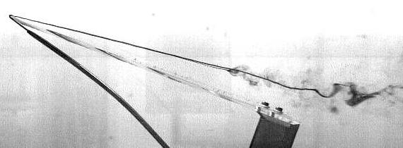
4 (SYA) 2-3 stream, passing through the wing model and in particular, focusing on the starboard primary and secondary LEV region. Flow visualization was conducted by injecting dye (mixture of food coloring and water) via a.5mm diameter probe into the nominal region about the windward stagnation point just after of the model apex. This probe can be seen as a thick dark line in the following visualization images. Location of the probe near to model line of symmetry resulted in dye entrainment into both port and starboard primary LEVs. A biasing of the probe location off-center resulted in most of the dye convecting along that wing panel s primary [and where applicable, secondary] LEV. Side-view and planform-view images were taken simultaneously by making use of the video and software techniques as for the SPIV setup. Figure and 5 wing models, with mounting arrangement Figure 2. Arrangement of PIV interrogation planes


5 (SYA) 2-4 Results Results for flow visualization are discussed first, with emphasis on the 5 wing. These data are then used to motivate the SPIV velocity data. Flow Visualization We consider three different situations: symmetric port and starboard primary LEVs; dye injection biased to reveal primary and secondary LEVs on one wing panel; and bulk unsteadiness in the entire vortex system. Stable symmetric primary LEVs Figure 3 shows essentially symmetric port and starboard primary LEVs for both wings at α = 5. For the 5 wing, loss of a steady continuous dye streak, akin to vortex breakdown, is observed aft of the trailing edge. For the 65 wing, a similar phenomenon is also observed, though not for approximately one root chord behind the trailing edge. At this low angle of attack, the LEV were weak but definitely visible. Progressing to α = 1 (Figure 4) shows straighter and more vigorous dye streaks, indicative of stronger primary LEVs. The 65 wing is qualitatively unchanged. However, the 5 wing exhibits symmetric classical breakdown at approximately x/c =.7. Flow inside and downstream of the breakdown regions is of course unsteady, but flow upstream of breakdown is steady, as is the position of the leading edges of the breakdown regions. By α = 2 (Figure 5), breakdown has crossed the trailing edge of the 65 wing. Figure 3. Dye streaks following primary LEVs for 5 and 65 wings, at α = 5 ; planform and side views.


6 (SYA) 2-5 Figure 4. Dye streaks following primary LEVs for 5 and 65 wings, at α = 1 ; planform and side views. Figure 5. Dye streaks following primary LEVs for 5 and 65 wings, at α = 2 ; planform and side views. 5 wing is completely stalled.


7 (SYA) 2-6 Secondary Vortices for the 5 wing In Figure 6, the starboard-side primary and secondary LEV dye streaks are shown. In going from 5 to 7.5 to 1 angle of attack, the secondary LEV is seen to undergo a breakdown-like behavior. At the lowest angle of attack, its dye streak is coherent all the way to the trailing edge. At the intermediate angle, the dye streak widens and the dye flow rate decelerates at approximately the midchord. At 1 angle of attack, the secondary LEV dye streak is very faint. Figure 6. Evolution of secondary LEV: α = 5, 7.5, and 1, 5 wing Unsteadiness of the 5 wing flowfield The higher angle of attack cases display marked unsteadiness that is, there is an apparent exchange of stability between the left and right primary LEVs. Unsteadiness downstream of the breakdown region, and in the vicinity of the VB region itself, has long been known. Here we investigate unsteadiness upstream of VB, with the observation that in the following cases - and only in the following cases was such flow behavior observed. The 65 wing has no such behavior at the angles of attack under consideration. Of course, at higher angles of attack, there is evidence that even quite slender wings have such LEV unsteadiness upstream of the VB point, en route to the complete flow separation at 9 angle of attack (Ayoub and McLachlan 2 ). Among the angles of attack considered here, appreciable unsteadiness was seen in the range of for the 5 wing, though some variation in the VB location is already displayed at 1. At 2, there was not enough recognizable LEV structure to consider unsteadiness to be relevant, beyond fluctuations in the shear layer bounding the leeward separation region (Figure 5). In the following, a typical time history for the 12.5 case is illustrated by a series of frame captured from video. Frame spacing in time is nondimensionalized with respect to convective time, * defined here as t = c / U, which for the 5 wing computes to 1.34 seconds, or ~4 video frames for a typical 3 frame/sec video camera. The series is started from nominal time zero. The question of periodicity in the destruction and reformation of coherent LEVs, or the upstream and downstream procession of the left and right VB, is intriguing but largely unresolved, due in part to the very long data records necessary to capture such a slowly evolving motion. Some qualitative observations are * given below. Frame time, t, is given in multiples of t.

8 (SYA) 2-7 t= t = 2.74 t = 4. t = 5.81 t = 7.33 t = 8.9 Figure 7. Typical sequence of port and starboard LEV behavior, 5 wing, α = 12.5 In going from t = to t=8.9, the behavior of the LEVs can be described as follows: a bubblelike VB region on the starboard side forms and moves upstream, while on the port side, an elongated bubble forms by coalescence of a wavy (but not spiral) breakdown structure. By t = 3, the port structure overtakes the starboard structure in its upstream movement. The starboard LEV then reforms, dissipating its VB bubble and replacing it with a wavy-type breakdown much further downstream, while the port-side elongated bubble lingers near the apex. By t=6 the port-side bubble also collapses to a tight vortex core, and the starboard-side VB region again coalesces to a bubble. This bubble then resumes its upstream journey, while the port-side VB region retreats further downstream and takes on a more typical spiral shape. Streamwise excursions of VB location are by no means unique to delta wings of moderate sweep, though in the case of wings of larger sweep, the excursions are of much lower extent. For example, the flow visualization data of Truneva 11 revealed streamwise VB excursions of about 1% of root chord, for a wing of 6 sweep at a Reynolds number of ~25. SPIV velocity data SPIV velocity vector plots are given below for the 5 (Figure 8) and 65 (Figure 9) wings. In an effort to illustrate three-component vector data from their two-dimensional domain, two views are given. The first is a streamwise view, with the free-stream direction normal to the page. The wing centerline is at x/c =. The second view is the planform view, edited to show only that portion of the interrogation domain which is at or below the z-cut passing through the primary LEV core. The colorbar legend indicates the total velocity magnitude, normalized by the free stream value.
9 (SYA) 2-8 Images are averages taken over 2 samples, which correspond to 2.8 and 5. convective times for the 65 and 5 wings, respectively α = 5 α = α = 1 α = α = 15 α = 2 Figure 8. Upstream and planform views of the mean starboard flow pattern, 5 wing; x/c =.296; coordinates expressed in fractions of local span.
10 (SYA) α = 5 α = α = 15 α = 2 Figure 9. Upstream and planform views of the mean starboard flow pattern, 65 wing; x/c =.296; coordinates expressed in fractions of local span. As expected, the LE shear layer and the LEVs are close to the wing leeward surface at the lowest angle of attack, and move progressively further above the wing with increasing angle of attack. For the 65 wing, axial velocity identifiable with the primary LEV increases with increasing angle of attack, from a value of nearly the same as free stream at 5, to almost twice that amount at 2. The latter is consistent with the usual observation the slender delta wing LEVs have high axial core velocity. But the 5 cases exhibit a wake-like axial velocity profile usually associated with the post-breakdown leading edge vortex, even when the primary LEV breakdown has clearly not yet cross the interrogation plane in question. Outboard of the primary LEV, some evidence of a secondary vortex is seen for the lower angle of attack cases. But by 1 angle of attack, the flow velocity magnitude outboard of the primary LEV and inboard of the LE shear layer is nearly zero, indicative of a nearly stagnant flow. This phenomenon was attributed to the effect of low Reynolds number. Unsteadiness in the 5 wing at moderate angles of attack In most cases, the averaged velocity data in Figure 8 and Figure 9 differ little from instantaneous data. But that is not the case for the 5 wing at intermediate angles of attack, as evidenced by the flow visualization. Figure 1 illustrates the situation for the 5 wing at α = 15. Four velocity vector plots represent data taken 1.25 convective times apart. Because true instantaneous data suffer from occasional outlier communication (i.e., spurious SPIV data not filtered in post-processing), images were averaged over 5 frames (that is,.12 convective times an interval small enough to retain all but the smallest features of unsteadiness).
11 (SYA) t = t = t = 2.5 t = 3.75 Figure 1. Upstream view of the evolving starboard flow pattern, 5 wing; x/c = Appreciable variation in the primary LEV axial velocity can be observed. A weak secondary vortex appears to first occupy its normal position, only to be swallowed by the primary LEV. This event is accompanied by an increase in primary LEV axial velocity. Curiously, the flow structure identifiable with this secondary LEV was not expected from the flow visualization data at this angle of attack. Discussion With the large data sets generated in these experiments, various derived quantities can be computed from the velocity field. In this paper, two- and three-component vorticity data are considered as examples of possible derived quantities. Others include primary LEV circulation and LEV core trajectories, which are considered further in 9. We first consider some profiles of the velocity field. Velocity Profiles By taking cuts along the appropriate distance above the leeward surface, velocity profiles can be constructed from the vector plots shown in the previous section. Again, one has to contend with the issue of how to represent three-dimensional data. The natural choice is to cut through the primary vortex core. Figure 11 shows these data for the station x/c =.296, for both wings and six angles of attack. Data are averaged over 2.8 convective times for the 65 wing, and 5. convective times for the 5 wing. The origin is again at the wing centerplane, and the local leading edge is at y =.5.
12 (SYA) 2-11 W _ _ _ _ 1 5 _ _ 5 V _ _ _ _ 1 5 _ _ 5.6 Figure 11. Mean axial and azimuthal velocity profiles, 5 and 65 wings, x/c =.296 It is seen from the first half of Figure 11 that the 65 wing has a jet-like axial velocity profile in the primary core at angles of attack above 5. This is modest at small angle of attack, but becomes quite pronounced by 15. The 5 wing, however, has a wake-like behavior at every angle of attack, regardless of whether vortex breakdown is upstream or downstream of the interrogation region. When breakdown has moved upstream of x/c =.296, the wake-like profile broadens, expanding further inboard. Complete-stall can be identified with the 2 angle of attack case, with the supposition that de-energized flow characteristic of stall is achieved when the wakelike profiles from the left and right LEVs coalesce at the wing center plane. In the v-component data, it is seen that there is a peak of positive azimuthal velocity at the wing leading edge, where the shear layer begins its rollup process, for every test case. For the 65 wing, there is the characteristic peak of opposite-signed azimuthal vorticity associated with the primary LEV core. For the 5 wing, the qualitative trend follows that of the 65 wing up to and including 12.5 angle of attack. As the angle of attack increases, data for the 5 and 65 wings progressively diverge. At 15 angle of attack, the velocity profile for the 5 wing changes abruptly, with a loss of velocity peak concomitant with the presence of VB. For the 65 wing there is a pronounced deficit of both axial and azimuthal velocity component between the primary LEV and the leading edge shear layer. The effect is also present for the 5 wing, albeit attenuated on account of the general lower axial velocity for that wing. This flow retardation is consistent with the results observed by Traub 12 for range for wings of 6 and 7 sweep at Re = 2,. Conical flow near the apex The previous data were presented for one streamwise station, x/c =.296. Presently we consider axial velocity profiles at the x/c =.118,.178,.237, and.296 stations, for the 5 wing at 12.5 and 15 angles of attack. These are shown in Figure 12, with the common abscissa renormalized with respect to local span.
13 (SYA) W deg, z/c = deg, z/c = deg, z/c = deg, z/c = deg, z/c = deg, z/c = deg, z/c = deg, z/c = V deg, z/c = deg, z/c = deg, z/c = deg, z/c = deg, z/c = deg, z/c = deg, z/c = deg, z/c =.296 Figure 12. Mean axial and azimuthal velocity profile sweeps, α = 12.5 and 15 With this rescaling, data for both the 12.5 and 15 AOA become nearly invariant with x/c station. This is strong indication of a conical velocity field. With the exceptions of the x/c = curve, and the x/c = curve, data in both AOA group almost overlap. In all the curves, the peak in axial velocity occurring near =.45 corresponds to the region just outboard of the LE shear layer, where the velocity magnitude is slightly larger than free stream. It is evident that for the 12.5 angle of attack case, axial flow in the LEV core is not appreciably retarded at any of the x/c stations. At the most aft station, axial flow is slightly smaller, evidently attributable to a stronger influence of breakdown. Outboard of the LEV, flow is strongly retarded, with a velocity magnitude of about.2u. For the 15 AOA case, the velocity profiles are rather different. Axial flow everywhere inside the region bounded by the rolled-up LE shear layer is markedly slower than the free stream speed, with the region outboard of the LEV remnant having reversed flow. The most upstream station lacks the outboard region of reversed flow, but it also lacks a discernable local velocity peak attributable to a LEV. In terms of the mean axial velocity profiles, it is not unreasonable to conclude that at 12.5 angle of attack, vortex breakdown occurs downstream of the domain of interrogation, but reaches the apex at 15 angle of attack. This is consistent with the flow visualizations, where the average VB location at 12.5 was at x/c ~.5, whereas at 15, on VB location in an averaged sense could be elucidated. Thus, contrary to initial expectation, the leeward-side flowfield appears to vary little in going downstream in the vicinity of the wing apex. Streamwise vorticity component Contours of axial vorticity are given in crossflow planes for the 65 wing and 5 wing for the representative case of 15 angle of attack (Figure 13). The scope of these data is essentially identical to what one would have obtained from classical 2-D PIV. Regions of high positive and negative vorticity are generally present in all data sets. The intermediate range of near-zero vorticity is contaminated by noise, either due to the numerical noise of differentiating discrete data, or of the general amplification of errors in PIV. Whereas it is clear from the velocity vector plots that the primary LEV core will be a region of strong axial vorticity, at least in crossflow planes upstream of breakdown, small regions of concentrated vorticity ( sub-structures ), such as those observed by Shih and Ding 3, Gad-el-Haq and Blackwelder 13, and others, can not be observed from the velocity plots alone. These were, however, clearly visible in the rolling-up shear layer and in the leeward surface
14 (SYA) 2-13 boundary layer, especially where the latter is close to the primary LEV. In these plots, the data are instantaneous. The actual numerical values of vorticity are to be viewed with caution, since peak values strongly skew the entire image, and these peaks are easily affected by numerical noise and the windowing resolution of PIV. This is especially apparent at the wing leading edge region. Also, it should be mentioned that the computed sign of vorticity is the reverse of the general convention. This is strictly a consequence of sign conventions introduced by intermediate calculations wing 5 wing Figure 13. Axial vorticity contours, 65 wing and 5 wing, α = 15 The 5 wing plot does not show an axial vorticity peak in the general vicinity of the primary LEV core. This differs from the classical pre-breakdown picture, such as that for the 65 wing for the same conditions. For both wings, a slab of vorticity of the opposite sense near the leeward boundary layer is also present in the region where the shear layer rollup approaches the wing leeward surface, but the phenomenon is much stronger for the 65 wing, where a coherent LEV is still present. The region between the boundary layer vorticity slab and the leading edge shear layer is largely devoid of vorticity, further supporting the assertion that this flow is essentially stagnant. Also in the 65 wing case, sub-structures of local vorticity peaks in the LEV core region, the LE shear layer and the near-surface slab are all mutually of the same sign, ruling out the presence of counter-rotating vortex pairs. But for the 5 wing, the shear layer exhibits regions of both positive and negative vorticity peaks. This has implications of the balance of vorticity production and convection over the entire flowfield of the wing 14. If the LE shear layer contains contour-rotating structures, there is no longer the need to sustain a stable LEV as a downstream sink of vorticity, as would have been the case were the vorticity in the LE shear layer all of one sign. Three vorticity components SPIV is only a semi-3d technique, since the interrogation domain is still planar. In the orientation of the present setup, streamwise-direction velocity gradients can not be measured directly. In particular, this means that SPIV does not yield any more information about the vorticity than does regular planar PIV. The streamwise gradients can, however, be obtained from a crude computational scheme by arranging three SPIV interrogation planes into a closely-spaced triplet. Central differencing of the velocity data window-by-window across these adjacent SPIV interrogation planes then yields all three components of vorticity, assembling the full vorticity vector, ω G. These data are only in the averaged sense, since the three SPIV interrogation planes are imaged sequentially and not simultaneously. Such 3-plane data were taken for the 65 and 5 wings at α=15 (Figure 14). Vorticity is shown as a vector field. First, the streamwise view is given. The color bar corresponds to the total
15 (SYA) 2-14 magnitude, whence there are no negative values. Next, the planform view is shown, for which the color bar corresponds to just the out-of-plane vorticity component W W Figure and 5 wing, α = 15, mean 3-component vorticity vector field, x/c =.296; streamwise and planform views Here we see strong out-of-plane vorticity in the LEV core, as expected for a slender delta wing. Vorticity at the wing leeward surface inboard of the primary attachment line is indicative of that produced by a boundary layer velocity profile and thus, of attached boundary layer flow. It should be noted that the peak value of out-of-plane vorticity component is smaller than that of the 2-D vorticity contour plots. This is for two reasons. First, the numerical method used to compute out-ofplane vorticity from planar data is less dissipative than the differencing method used for the 3-D vorticity. Second, the source of the 2-D plots is instantaneous data, while for the 3-D plots it is averaged data. The 5 wing α=15 case exhibits appreciably less vorticity in the region bounded by the rolling-up shear layer. The planform view of the vorticity field shows that there is still a vortical structure identifiable as the primary LEV. But the vorticity in the shear layer, especially the region nearest the leading edge, is certainly dominant. Conclusions The slenderness of a delta wing has a more pronounced effect on the vortex flowfield as angle of attack increases. At α = 5, the 5 and 65 exhibited remarkably similar velocity distributions over the leeward side, at least in regions far from the trailing edge. But as angle of attack was increased, the flowfield features of the two wings progressively diverged. The 5 wing exhibits a stable separated vortical flow at angles of attack below 1 ; in particular, primary LEVs are present over the entire planform at 5 and below. However, the axial velocity in the primary LEV core never exceeds the free stream velocity, even well upstream of any observable breakdown. By 2 the leeward flow is essentially stalled, with no evidence of a residual LEV. In going from the former to the latter condition, several steps were identified. The first of these is the decay of the secondary LEV, and gradual upstream progression of the primary LEV breakdown point. Then, in the range, the primary LEV breakdown is highly unsteady and sweeps over the forward half of the wing planform. By 15 the LEVs are sufficiently weakened that breakdown-like state appears to cover the entire planform. Finally, by 2, flow inboard of the primary LEVs is itself stalled, yet an organized leading edge shear layer rollup is still observed. At the Reynolds numbers considered in this investigation, flow outboard of the primary LEV is unexpectedly weak, while the region of the velocity profiles normally associated with the primary LEV is quite broad.
16 (SYA) 2-15 In further work, it would be interesting to extend the SPIV results to the 65 wing at higher angles of attack, and to consider the trailing edge region and the near wake of both wings. Also, since the 5 wing exhibits definite leading edge vortices, wings of yet lower sweep should be tested to ascertain a more extreme bound for sweep where coherent leading edge vortical flow is no longer possible. Finally, more work needs to be done to ascertain the parametric dependency of the flow field on Reynolds number, especially if results from low-re experimental data are to be associated with high-re applications. The abruptness of the stall of the 5 wing, the large-scale unsteadiness en route to stall and the presence of a coherent leading edge shear layer long after LEV breakdown are qualitatively indicative of a transitional case from slender delta wing separation to classical airfoil stall. References 1 Kuechemann, D. The Aerodynamic Design of Aircraft Ayoub, A., and McLachlan, B.G. Slender Delta Wing at High Angles of Attack a Flow Visualization Study. AIAA paper # , June Shih, C., and Ding, Z. Unsteady Structure of Leading-Edge Vortex Flow over a Delta Wing. AIAA paper # , January Erickson, G.E. Water Tunnel Studies of Leading-Edge Vortices. J. Aircraft, Vol. 19, No. 6, pp Poisson-Quinton, P. and Werle, H. Water-Tunnel Visualization of Vortex Flow. Aeronautics and Astronautics, June 1967, pp Thompson, D.H. A Water Tunnel Study of Vortex Breakdown over Delta Wings with Highly Swept Leading Edges. Aerodynamics Note 356, A.R.L. (Australia), May Miau, J.J., Kuo, K.T., Liu, W.H., Hsieh, S.J., Chou, J.H., and Lin, C.K. Flow Developments above 5-Deg Sweep Delta Wings with Different Leading-Edge Profiles. J. Aircraft, Vol. 32, No. 4, Jul- Aug Earnshaw, P.B., and Lawford, J.A. Low-Speed Wind Tunnel Experiments on a Series of Sharp- Edged Delta Wings. Reports and Memorabilia, No. 3424, March Ol, M. The Passage Toward Stall of Nonslender Delta Wings and Low Reynolds Number. Ph.D. thesis, Caltech, Willert, C.E. Stereoscopic Digital Particle Image Velocimetry for Application in Wind Tunnel Flows. Meas. Sci. Technol., Vol. 8, 1997, pp Truneva, E.A. On the Mechanism of Vortex Breakdown Point Stabilization for a Low-Subsonic Flow about a Delta Wing. Bulletin of Institutes of Higher Education, Aviation Tech. (USSR), Vol. 19, No. 2, Traub, L. Low-Reynolds-Number Effects on Delta Wing Aerodynamics. J. Aircraft, Vol. 35, No. 4, 1998, pp Gad-el-Haq, M. and Blackwelder, R. F. The Discrete Vortices from a Delta Wing. AIAA Journal. Vol. 23, No. 6, June 1985, pp Lee, M. and Ho, C.-M., Lift Force of Delta Wings. ASME; Appl. Mech. Rev. Vol 43, No 9, September 199, pp
17 (SYA) 2-16 Paper: #2 Author: Dr. Ol Question by Dr. Luckring: First let me comment that Smith's similarity parameter "a" would be a better correlation parameter to use than, especially since you are comparing two delta wings of different sweep. My question is whether you have calibrated your facility for predicting vortex breakdown locations against established data sets, such as due to Dr. Hummel or Prof. Wentz? Answer: No, no such calibration has been done.
AN EXPERIMENTAL INVESTIGATION OF SPILLING BREAKERS
 AN EXPERIMENTAL INVESTIGATION OF SPILLING BREAKERS Prof. James H. Duncan Department of Mechanical Engineering University of Maryland College Park, Maryland 20742-3035 phone: (301) 405-5260, fax: (301)
AERODYNAMIC CHARACTERISTICS OF SPIN PHENOMENON FOR DELTA WING
 ICAS 2002 CONGRESS AERODYNAMIC CHARACTERISTICS OF SPIN PHENOMENON FOR DELTA WING Yoshiaki NAKAMURA (nakamura@nuae.nagoya-u.ac.jp) Takafumi YAMADA (yamada@nuae.nagoya-u.ac.jp) Department of Aerospace Engineering,
Keywords: dynamic stall, free stream turbulence, pitching airfoil
 Applied Mechanics and Materials Vol. 225 (2012) pp 103-108 Online available since 2012/Nov/29 at www.scientific.net (2012) Trans Tech Publications, Switzerland doi:10.4028/www.scientific.net/amm.225.103
Lift for a Finite Wing. all real wings are finite in span (airfoils are considered as infinite in the span)
") Lift for a Finite Wing all real wings are finite in span (airfoils are considered as infinite in the span) The lift coefficient differs from that of an airfoil because there are strong vortices produced
Lift for a Finite Wing all real wings are finite in span (airfoils are considered as infinite in the span) The lift coefficient differs from that of an airfoil because there are strong vortices produced
Tim Lee s journal publications
 Tim Lee s journal publications 82. Lee, T., and Tremblay-Dionne, V., (2018) Impact of wavelength and amplitude of a wavy ground on a static NACA 0012 airfoil submitted to Journal of Aircraft (paper in
Stability & Control Aspects of UCAV Configurations
 Stability & Control Aspects of UCAV Configurations Paul Flux Senior Aerodynamicist BAE SYSTEMS Air Programmes Report Documentation Page Form Approved OMB No. 0704-0188 Public reporting burden for the collection
 et al. [25], Noack et al. [26] for circular cylinder flows, Van Oudheusden [27] for square cylinder and Durgesh [28] for a flat plate model. The first two modes appear as phase-shifted versions of each
Wind tunnel effects on wingtip vortices
 48th AIAA Aerospace Sciences Meeting Including the New Horizons Forum and Aerospace Exposition 4-7 January 2010, Orlando, Florida AIAA 2010-325 Wind tunnel effects on wingtip vortices Xin Huang 1, Hirofumi
GEOMETRY TIP CAP EFFECTS ON FORMATION AND NEAR WAKE EVOLUTION OF THE ROTOR TIP VORTICES
 36th AIAA Fluid Dynamics Conference and Exhibit 5-8 June 2006, San Francisco, California AIAA 2006-3376 GEOMETRY TIP CAP EFFECTS ON FORMATION AND NEAR WAKE EVOLUTION OF THE ROTOR TIP VORTICES Roxana Vasilescu
Inlet Influence on the Pressure and Temperature Distortion Entering the Compressor of an Air Vehicle
 Distortion Entering the Compressor of an Air Vehicle P. Hendrick Université Libre de Bruxelles, ULB Avenue F.D. Roosevelt, 50 1050 Brussels BELGIUM patrick.hendrick@ulb.ac.be ABSTRACT One of the possible
JOURNAL PUBLICATIONS
 1 JOURNAL PUBLICATIONS 71. Lee, T., Mageed, A., Siddiqui, B. and Ko, L.S., (2016) Impact of ground proximity on aerodynamic properties of an unsteady NACA 0012 airfoil, submitted to Journal of Aerospace
AERODYNAMICS I LECTURE 7 SELECTED TOPICS IN THE LOW-SPEED AERODYNAMICS
 LECTURE 7 SELECTED TOPICS IN THE LOW-SPEED AERODYNAMICS The sources of a graphical material used in this lecture are: [UA] D. McLean, Understanding Aerodynamics. Arguing from the Real Physics. Wiley, 2013.
The effect of back spin on a table tennis ball moving in a viscous fluid.
 How can planes fly? The phenomenon of lift can be produced in an ideal (non-viscous) fluid by the addition of a free vortex (circulation) around a cylinder in a rectilinear flow stream. This is known as
STUDIES ON THE OPTIMUM PERFORMANCE OF TAPERED VORTEX FLAPS
 ICAS 2000 CONGRESS STUDIES ON THE OPTIMUM PERFORMANCE OF TAPERED VORTEX FLAPS Kenichi RINOIE Department of Aeronautics and Astronautics, University of Tokyo, Tokyo, 113-8656, JAPAN Keywords: vortex flap,
Results and Discussion for Steady Measurements
 Chapter 5 Results and Discussion for Steady Measurements 5.1 Steady Skin-Friction Measurements 5.1.1 Data Acquisition and Reduction A Labview software program was developed for the acquisition of the steady
Air-Sea Interaction Spar Buoy Systems
 DISTRIBUTION STATEMENT A: Distribution approved for public release; distribution is unlimited Air-Sea Interaction Spar Buoy Systems Hans C. Graber CSTARS - University of Miami 11811 SW 168 th Street, Miami,
Anna University Regional office Tirunelveli
 Effect of Tubercle Leading Edge Control Surface on the Performance of the Double Delta Wing Fighter Aircraft P Sharmila 1, S Rajakumar 2 1 P.G. Scholar, 2 Assistant Professor, Mechanical Department Anna
CIRCULATION PRODUCTION AND SHEDDING FROM VERTICAL AXIS WIND TURBINE BLADES UNDERGOING DYNAMIC STALL
 June 3 - July 3, 5 Melbourne, Australia 9 7D-3 CIRCULATION PRODUCTION AND SHEDDING FROM VERTICAL AXIS WIND TURBINE BLADES UNDERGOING DYNAMIC STALL Abel-John Buchner,,, Julio Soria,3, Alexander J. Smits,
High Swept-back Delta Wing Flow
 Advanced Materials Research Submitted: 2014-06-25 ISSN: 1662-8985, Vol. 1016, pp 377-382 Accepted: 2014-06-25 doi:10.4028/www.scientific.net/amr.1016.377 Online: 2014-08-28 2014 Trans Tech Publications,
High-Frequency Scattering from the Sea Surface and Multiple Scattering from Bubbles
 High-Frequency Scattering from the Sea Surface and Multiple Scattering from Bubbles Peter H. Dahl Applied Physics Laboratory College of Ocean and Fisheries Sciences University of Washington Seattle, Washington
Experimental and Theoretical Investigation for the Improvement of the Aerodynamic Characteristic of NACA 0012 airfoil
 International Journal of Mining, Metallurgy & Mechanical Engineering (IJMMME) Volume 2, Issue 1 (214) ISSN 232 46 (Online) Experimental and Theoretical Investigation for the Improvement of the Aerodynamic
AFRL-RX-WP-TP
 AFRL-RX-WP-TP-2012-0215 REVERSE PRESSURE CAPABLE FINGER SEAL (PREPRINT) Nathan Gibson and Joe Yanof Honeywell International, Inc. JANUARY 2012. See additional restrictions described on inside pages STINFO
VORTEX BEHAVIORS OVER A CRANKED ARROW WING CONFIGURATION AT HIGH ANGLES OF ATTACK
 24 TH INTERNATIONAL CONGRESS OF THE AERONAUTICAL SCIENCES VORTEX BEHAVIORS OVER A CRANKED ARROW WING CONFIGURATION AT HIGH ANGLES OF ATTACK Dong-Youn KWAK*, Masashi SHIROTAKE** and Kenichi RINOIE** *Japan
The Effect of Gurney Flap Height on Vortex Shedding Modes Behind Symmetric Airfoils
 The Effect of Gurney Flap Height on Vortex Shedding Modes Behind Symmetric Airfoils Daniel R. Troolin 1, Ellen K. Longmire 2, Wing T. Lai 3 1: TSI Incorporated, St. Paul, USA, dan.troolin@tsi.com 2: University
z Interim Report for May 2004 to October 2005 Aircrew Performance and Protection Branch Wright-Patterson AFB, OH AFRL-HE-WP-TP
 AFRL-HE-WP-TP-26-89 Neck Muscle Fatigue with Helmet-Mounted Systems Edward S. Eveland Joseph A. Pellettiere Air Force Research Laboratory LL September 26 z Interim Report for May 24 to October 25 (n 261124
Characterizing The Surf Zone With Ambient Noise Measurements
 Characterizing The Surf Zone With Ambient Noise Measurements LONG-TERM GOAL Grant Deane Marine Physical Laboratory Scripps Institution of Oceanography La Jolla, CA 93093-0213 phone: (619) 534-0536 fax:
A comparison of NACA 0012 and NACA 0021 self-noise at low Reynolds number
 A comparison of NACA 12 and NACA 21 self-noise at low Reynolds number A. Laratro, M. Arjomandi, B. Cazzolato, R. Kelso Abstract The self-noise of NACA 12 and NACA 21 airfoils are recorded at a Reynolds
THE COLLEGE OF AERONAUTICS CRANFIELD
 THE COLLEGE OF AERONAUTICS CRANFIELD AERODYNAMIC CHARACTERISTICS OF A 40 SWEPT BACK WING OF ASPECT RATIO 4.5 by P. S. BARNA NOTE NO. 65 MAY, 1957 CRANFIELD A preliminary report on the aerodynamic characteristics
Lecture # 08: Boundary Layer Flows and Drag
 AerE 311L & AerE343L Lecture Notes Lecture # 8: Boundary Layer Flows and Drag Dr. Hui H Hu Department of Aerospace Engineering Iowa State University Ames, Iowa 511, U.S.A y AerE343L #4: Hot wire measurements
THREE DIMENSIONAL STRUCTURES OF FLOW BEHIND A
 The Seventh Asia-Pacific Conference on Wind Engineering, November 8-12, 29, Taipei, Taiwan THREE DIMENSIONAL STRUCTURES OF FLOW BEHIND A SQUARE PRISM Hiromasa Kawai 1, Yasuo Okuda 2 and Masamiki Ohashi
Computational Analysis of the S Airfoil Aerodynamic Performance
 Computational Analysis of the 245-3S Airfoil Aerodynamic Performance Luis Velazquez-Araque and Jiří Nožička 2 Department of Mechanical Engineering National University of Táchira, San Cristóbal 5, Venezuela
SEMI-SPAN TESTING IN WIND TUNNELS
 25 TH INTERNATIONAL CONGRESS OF THE AERONAUTICAL SCIENCES SEMI-SPAN TESTING IN WIND TUNNELS S. Eder, K. Hufnagel, C. Tropea Chair of Fluid Mechanics and Aerodynamics, Darmstadt University of Technology
Unsteady airfoil experiments
 Unsteady airfoil experiments M.F. Platzer & K.D. Jones AeroHydro Research & Technology Associates, Pebble Beach, CA, USA. Abstract This paper describes experiments that elucidate the dynamic stall phenomenon
Waves, Turbulence and Boundary Layers
 Waves, Turbulence and Boundary Layers George L. Mellor Program in Atmospheric and Oceanic Sciences Princeton University Princeton NJ 8544-71 phone: (69) 258-657 fax: (69) 258-285 email: glm@splash.princeton.edu
CFD AND EXPERIMENTAL STUDY OF AERODYNAMIC DEGRADATION OF ICED AIRFOILS
 Colloquium FLUID DYNAMICS 2008 Institute of Thermomechanics AS CR, v.v.i., Prague, October 22-24, 2008 p.1 CFD AND EXPERIMENTAL STUDY OF AERODYNAMIC DEGRADATION OF ICED AIRFOILS Vladimír Horák 1, Dalibor
Computational Analysis of Cavity Effect over Aircraft Wing
 World Engineering & Applied Sciences Journal 8 (): 104-110, 017 ISSN 079-04 IDOSI Publications, 017 DOI: 10.589/idosi.weasj.017.104.110 Computational Analysis of Cavity Effect over Aircraft Wing 1 P. Booma
Experimental investigation on the aft-element flapping of a two-element airfoil at high attack angle
 Experimental investigation on the aft-element flapping of a two-element airfoil at high attack angle Tan Guang-kun *, Shen Gong-xin, Su Wen-han Beijing University of Aeronautics and Astronautics (BUAA),
Waves, Bubbles, Noise, and Underwater Communications
 Waves, Bubbles, Noise, and Underwater Communications Grant B. Deane Marine Physical Laboratory, Scripps Institution of Oceanography UCSD, La Jolla, CA 92093-0238 phone: (858) 534-0536 fax: (858) 534-7641
Internal Waves and Mixing in the Aegean Sea
 Internal Waves and Mixing in the Aegean Sea Michael C. Gregg Applied Physics Laboratory, University of Washington 1013 NE 40 th St. Seattle, WA 98105-6698 phone: (206) 543-1353 fax: (206) 543-6785 email:
Experimental Investigation into the Aerodynamic Stability of a Suborbital Reusable Booster Concept
 50th AIAA Aerospace Sciences Meeting including the New Horizons Forum and Aerospace Exposition 09-12 January 2012, Nashville, Tennessee AIAA 2012-1216 Experimental Investigation into the Aerodynamic Stability
PIV Analysis of a Delta Wing Flow with or without LEX(Leading Edge Extension)
") PIV Analysis of a Delta Wing Flow with or without LEX(Leading Edge Extension) by Young-Ho LEE (1) (Korea Maritime University), Myong-Hwan SOHN (2) (Korea Air Force Academy) Hyun LEE (3), Jung-Hwan KIM
PIV Analysis of a Delta Wing Flow with or without LEX(Leading Edge Extension) by Young-Ho LEE (1) (Korea Maritime University), Myong-Hwan SOHN (2) (Korea Air Force Academy) Hyun LEE (3), Jung-Hwan KIM
Influence of wing span on the aerodynamics of wings in ground effect
 Influence of wing span on the aerodynamics of wings in ground effect Sammy Diasinos 1, Tracie J Barber 2 and Graham Doig 2 Abstract A computational fluid dynamics study of the influence of wing span has
NUMERICAL INVESTIGATION OF THE FLOW BEHAVIOUR IN A MODERN TRAFFIC TUNNEL IN CASE OF FIRE INCIDENT
 - 277 - NUMERICAL INVESTIGATION OF THE FLOW BEHAVIOUR IN A MODERN TRAFFIC TUNNEL IN CASE OF FIRE INCIDENT Iseler J., Heiser W. EAS GmbH, Karlsruhe, Germany ABSTRACT A numerical study of the flow behaviour
Kelly Legault, Ph.D., P.E. USACE SAJ
 Kelly Legault, Ph.D., P.E. USACE SAJ Report Documentation Page Form Approved OMB No. 0704-0188 Public reporting burden for the collection of information is estimated to average 1 hour per response, including
The subsonic compressibility effect is added by replacing. with
 Swept Wings The main function of a swept wing is to reduce wave drag at transonic and supersonic speeds. Consider a straight wing and a swept wing in a flow with a free-stream velocity V. Assume that the
Low Speed Wind Tunnel Wing Performance
 Low Speed Wind Tunnel Wing Performance ARO 101L Introduction to Aeronautics Section 01 Group 13 20 November 2015 Aerospace Engineering Department California Polytechnic University, Pomona Team Leader:
THE BRIDGE COLLAPSED IN NOVEMBER 1940 AFTER 4 MONTHS OF ITS OPENING TO TRAFFIC!
 OUTLINE TACOMA NARROWS BRIDGE FLOW REGIME PAST A CYLINDER VORTEX SHEDDING MODES OF VORTEX SHEDDING PARALLEL & OBLIQUE FLOW PAST A SPHERE AND A CUBE SUMMARY TACOMA NARROWS BRIDGE, USA THE BRIDGE COLLAPSED
Effect of Flapping Frequency and Leading Edge Profile on Airfoil Leading Edge Vortical Structures
 Effect of Flapping Frequency and Leading Edge Profile on Airfoil Leading Edge Vortical Structures Wesley N. Fassmann Brigham Young University Scott L. Thomson Brigham Young University Abstract By varying
IMPACT OF FUSELAGE CROSS SECTION ON THE STABILITY OF A GENERIC FIGHTER
 IMPACT OF FUSELAGE CROSS SECTION ON THE STABILITY OF A GENERIC FIGHTER Robert M. Hall NASA Langley Research Center Hampton, Virginia ABSTRACT Many traditional data bases, which involved smooth-sided forebodies,
HEFAT th International Conference on Heat Transfer, Fluid Mechanics and Thermodynamics July 2012 Malta
 HEFAT212 9 th International Conference on Heat Transfer, Fluid Mechanics and Thermodynamics 16 18 July 212 Malta AN EXPERIMENTAL STUDY OF SWEEP ANGLE EFFECTS ON THE TRANSITION POINT ON A 2D WING BY USING
Unsteady Flows and Airfoil-Vortex Interaction
 (SYA) 12-1 Unsteady Flows and Airfoil-Vortex Interaction M. Mamou, M. Khalid and H. Xu Institute for Aerospace Research National Research Council Ottawa, K1A 0R6, Ontario, Canada Mahmoud.Mamou@nrc.ca Abstract
AN EXPERIMENTAL STUDY OF THE EFFECTS OF SWEPT ANGLE ON THE BOUNDARY LAYER OF THE 2D WING
 AN EXPERIMENTAL STUDY OF THE EFFECTS OF SWEPT ANGLE ON THE BOUNDARY LAYER OF THE 2D WING A. Davari *, M.R. Soltani, A.Tabrizian, M.Masdari * Assistant Professor, Department of mechanics and Aerospace Engineering,
L'evoluzione delle tecniche sperimentali nell'idrodinamica navale Particle Image Velocimetry, potenzialità, criticità ed applicazioni
 L'evoluzione delle tecniche sperimentali nell'idrodinamica navale Particle Image Velocimetry, potenzialità, criticità ed applicazioni Massimo Falchi, Mario Felli, Giovanni Aloisio, Silvano Grizzi, Fabio
Group Project Flume Airfoil Flow
 Group Project Flume Airfoil Flow Alexander B. Meyer Mechanical Engineering I. Background This project was the first team assignment of our Flow Visualization course at the University of Colorado at Boulder.
Study of a Swept Wing with Leading-Edge Ice Using a Wake Survey Technique
 51st AIAA Aerospace Sciences Meeting including the New Horizons Forum and Aerospace Exposition 7-1 January 213, Grapevine (Dallas/Ft. Worth Region), Texas AIAA 213-245 Study of a Swept Wing with Leading-Edge
COMPUTATIONAL FLOW MODEL OF WESTFALL'S LEADING TAB FLOW CONDITIONER AGM-09-R-08 Rev. B. By Kimbal A. Hall, PE
 COMPUTATIONAL FLOW MODEL OF WESTFALL'S LEADING TAB FLOW CONDITIONER AGM-09-R-08 Rev. B By Kimbal A. Hall, PE Submitted to: WESTFALL MANUFACTURING COMPANY September 2009 ALDEN RESEARCH LABORATORY, INC.
Internal Waves in Straits Experiment Progress Report
 DISTRIBUTION STATEMENT A: Approved for public release; distribution is unlimited. Internal Waves in Straits Experiment Progress Report Jody Klymak School of Earth and Ocean Sciences University of Victoria
Aerodynamic Analysis of a Symmetric Aerofoil
 214 IJEDR Volume 2, Issue 4 ISSN: 2321-9939 Aerodynamic Analysis of a Symmetric Aerofoil Narayan U Rathod Department of Mechanical Engineering, BMS college of Engineering, Bangalore, India Abstract - The
NUMERICAL SIMULATION OF ACTIVE FLOW CONTROL BASED ON STREAMWISE VORTICES FOR A BLUNT TRAILING EDGE AIRFOIL
 BBAA VI International Colloquium on: Bluff Bodies Aerodynamics & Applications Milano, Italy, July, 20-24 2008 NUMERICAL SIMULATION OF ACTIVE FLOW CONTROL BASED ON STREAMWISE VORTICES FOR A BLUNT TRAILING
EXPERIMENTAL ANALYSIS OF THE CONFLUENT BOUNDARY LAYER BETWEEN A FLAP AND A MAIN ELEMENT WITH SAW-TOOTHED TRAILING EDGE
 24 TH INTERNATIONAL CONGRESS OF THE AERONAUTICAL SCIENCES EXPERIMENTAL ANALYSIS OF THE CONFLUENT BOUNDARY LAYER BETWEEN A FLAP AND A MAIN ELEMENT WITH SAW-TOOTHED TRAILING EDGE Lemes, Rodrigo Cristian,
Computational Investigation of Airfoils with Miniature Trailing Edge Control Surfaces
 AIAA-24-5 Computational Investigation of Airfoils with Miniature Trailing Edge Control Surfaces Hak-Tae Lee, Ilan M. Kroo Stanford University, Stanford, CA 9435 Abstract Miniature trailing edge effectors
AERODYNAMIC CHARACTERISTICS OF NACA 0012 AIRFOIL SECTION AT DIFFERENT ANGLES OF ATTACK
 AERODYNAMIC CHARACTERISTICS OF NACA 0012 AIRFOIL SECTION AT DIFFERENT ANGLES OF ATTACK SUPREETH NARASIMHAMURTHY GRADUATE STUDENT 1327291 Table of Contents 1) Introduction...1 2) Methodology.3 3) Results...5
DYAMIC BEHAVIOR OF VORTEX SHEDDING FROM AN OSCILLATING THREE-DIMENSIONAL AIRFOIL
 27 TH INTERNATIONAL CONGRESS OF THE AERONAUTICAL SCIENCES DYAMIC BEHAVIOR OF VORTEX SHEDDING FROM AN OSCILLATING THREE-DIMENSIONAL AIRFOIL Hiroaki Hasegawa*, Kennichi Nakagawa** *Department of Mechanical
EXPERIMENTAL INVESTIGATION OF THE EFFECT OF VARIOUS WINGLET SHAPES ON THE TOTAL PRESSURE DISTRIBUTION BEHIND A WING
 24 TH INTERNATIONAL CONGRESS OF THE AERONAUTICAL SCIENCES EXPERIMENTAL INVESTIGATION OF THE EFFECT OF VARIOUS WINGLET SHAPES ON THE TOTAL PRESSURE DISTRIBUTION BEHIND A WING Mohammad Reza Soltani, Kaveh
FLUID FORCE ACTING ON A CYLINDRICAL PIER STANDING IN A SCOUR
 BBAA VI International Colloquium on: Bluff Bodies Aerodynamics & Applications Milano, Italy, July, 20-24 2008 FLUID FORCE ACTING ON A CYLINDRICAL PIER STANDING IN A SCOUR Takayuki Tsutsui Department of
Lecture # 08: Boundary Layer Flows and Controls
 AerE 344 Lecture Notes Lecture # 8: Boundary Layer Flows and Controls Dr. Hui Hu Department of Aerospace Engineering Iowa State University Ames, Iowa 511, U.S.A Flow Separation on an Airfoil Quantification
WIND TUNNEL MEASUREMENTS AND CALCULATIONS OF AERODYNAMIC INTERACTIONS BETWEEN TILTROTOR AIRCRAFT
 WIND TUNNEL MEASUREMENTS AND CALCULATIONS OF AERODYNAMIC INTERACTIONS BETWEEN TILTROTOR AIRCRAFT Wayne Johnson Gloria K. Yamauchi Army/NASA Rotorcraft Division Moffett Field, California Michael R. Derby
Using SolidWorks & CFD to Create The Next Generation Airlocks
 Using SolidWorks & CFD to Create The Next Generation Airlocks Matthew Gaffney Mechanical Engineer Geo-Centers, INC US Army Natick Soldier Center Natick, MA 01760 508-233-5557 Matthew.gaffney@natick.army.mil
VORTICITY CONCENTRATION AT THE EDGE OF THE INBOARD VORTEX SHEET
 Submitted to the Journal of the American Helicopter Society VORTICITY CONCENTRATION AT THE EDGE OF THE INBOARD VORTEX SHEET J.M. Kim 1, N.M. Komerath 2, S.G. Liou 3 School of Aerospace Engineering Georgia
ANALYSIS OF AERODYNAMIC CHARACTERISTICS OF A SUPERCRITICAL AIRFOIL FOR LOW SPEED AIRCRAFT
 ANALYSIS OF AERODYNAMIC CHARACTERISTICS OF A SUPERCRITICAL AIRFOIL FOR LOW SPEED AIRCRAFT P.Sethunathan 1, M.Niventhran 2, V.Siva 2, R.Sadhan Kumar 2 1 Asst.Professor, Department of Aeronautical Engineering,
Acoustic Focusing in Shallow Water and Bubble Radiation Effects
 Acoustic Focusing in Shallow Water and Bubble Radiation Effects Grant B. Deane Marine Physical Laboratory, Scripps Institution of Oceanography UCSD, La Jolla, CA 92093-0238 Phone: (858) 534-0536 fax: (858)
Hydrogen Bubble Seeding for Particle Image Velocimetry
 Hydrogen Bubble Seeding for Particle Image Velocimetry Benjamin T. Hillier 1 and Mitchell A. Schram. 2 The University of Melbourne, Melbourne, Victoria, 3010, Australia Dr. Jason P. Monty 3 The University
High fidelity gust simulations around a transonic airfoil
 High fidelity gust simulations around a transonic airfoil AEROGUST Workshop 27 th - 28 th April 2017, University of Liverpool Presented by B. Tartinville (Numeca) Outline of the presentation 1Objectives
Asymmetric vortex shedding flow past an inclined flat plate at high incidence
 Title Asymmetric vortex shedding flow past an inclined flat plate at high incidence Author(s) Lam, KM; Leung, MYH Citation European Journal Of Mechanics, B/Fluids, 5, v. 4 n., p. - 48 Issued Date 5 URL
Rip Currents Onshore Submarine Canyons: NCEX Analysis
 Rip Currents Onshore Submarine Canyons: NCEX Analysis Dr. Thomas C. Lippmann Civil and Environmental Engineering & Geodetic Science, Byrd Polar Research Center, 1090 Carmack Rd., Ohio State University,
EXPERIMENTAL STUDY OF WIND PRESSURES ON IRREGULAR- PLAN SHAPE BUILDINGS
 BBAA VI International Colloquium on: Bluff Bodies Aerodynamics & Applications Milano, Italy, July, 2-24 8 EXPERIMENTAL STUDY OF WIND PRESSURES ON IRREGULAR- PLAN SHAPE BUILDINGS J. A. Amin and A. K. Ahuja
Inlet Influence on the Pressure and Temperature Distortion Entering the Compressor of an Air Vehicle
 Distortion Entering the Compressor of an Air Vehicle P. Hendrick Université Libre de Bruxelles, ULB Avenue F.D. Roosevelt, 50 1050 Brussels BELGIUM patrick.hendrick@ulb.ac.be ABSTRACT One of the possible
Citation Journal of Thermal Science, 18(4),
,") NAOSITE: Nagasaki University's Ac Title Author(s) Noise characteristics of centrifuga diffuser (Noise reduction by means leading tip) Murakami, Tengen; Ishida, Masahiro; Citation Journal of Thermal Science,
NAOSITE: Nagasaki University's Ac Title Author(s) Noise characteristics of centrifuga diffuser (Noise reduction by means leading tip) Murakami, Tengen; Ishida, Masahiro; Citation Journal of Thermal Science,
Reynolds Number Effects on Leading Edge Vortices
 Reynolds Number Effects on Leading Edge Vortices Taken From AIAA-2002-2839 Paper Reynolds Numbers Considerations for Supersonic Flight Brenda M. Kulfan 32nd AIAA Fluid Dynamics Conference and Exhibit St.
Observations of Velocity Fields Under Moderately Forced Wind Waves
 Observations of Velocity Fields Under Moderately Forced Wind Waves Timothy P. Stanton Oceanography Department, Code OC/ST Naval Postgraduate School Monterey, CA 93943-5000 phone: (831) 656 3144 fax: (831)
Ermenek Dam and HEPP: Spillway Test & 3D Numeric-Hydraulic Analysis of Jet Collision
 Ermenek Dam and HEPP: Spillway Test & 3D Numeric-Hydraulic Analysis of Jet Collision J.Linortner & R.Faber Pöyry Energy GmbH, Turkey-Austria E.Üzücek & T.Dinçergök General Directorate of State Hydraulic
Aerodynamic Analysis of Blended Winglet for Low Speed Aircraft
 , July 1-3, 2015, London, U.K. Aerodynamic Analysis of Blended Winglet for Low Speed Aircraft Pooja Pragati, Sudarsan Baskar Abstract This paper provides a practical design of a new concept of massive
AE Dept., KFUPM. Dr. Abdullah M. Al-Garni. Fuel Economy. Emissions Maximum Speed Acceleration Directional Stability Stability.
 Aerodynamics: Introduction Aerodynamics deals with the motion of objects in air. These objects can be airplanes, missiles or road vehicles. The Table below summarizes the aspects of vehicle performance
J. Szantyr Lecture No. 21 Aerodynamics of the lifting foils Lifting foils are important parts of many products of contemporary technology.
 J. Szantyr Lecture No. 21 Aerodynamics of the lifting foils Lifting foils are important parts of many products of contemporary technology. < Helicopters Aircraft Gliders Sails > < Keels and rudders Hydrofoils
Investigation of Suction Process of Scroll Compressors
 Purdue University Purdue e-pubs International Compressor Engineering Conference School of Mechanical Engineering 2006 Investigation of Suction Process of Scroll Compressors Michael M. Cui Trane Jack Sauls
Cavitation Bubbles in a Starting Submerged Water Jet
 CAV21:sessionA7.5 1 Cavitation Bubbles in a Starting Submerged Water Jet K.Nakano, M.Hayakawa, S.Fujikawa and T.Yano Graduate School of Engineering, Hokkaido University, Sapporo, Japan Abstract The behavior
Aerofoil Design for Man Powered Aircraft
 Man Powered Aircraft Group Aerofoil Design for Man Powered Aircraft By F. X. Wortmann Universitat Stuttgart From the Second Man Powered Aircraft Group Symposium Man Powered Flight The Way Ahead 7 th February
Design & Analysis of Natural Laminar Flow Supercritical Aerofoil for Increasing L/D Ratio Using Gurney Flap
 Design & Analysis of Natural Laminar Flow Supercritical Aerofoil for Increasing L/D Ratio Using Gurney Flap U.Praveenkumar 1, E.T.Chullai 2 M.Tech Student, School of Aeronautical Science, Hindustan University,
IMPROVED BLADE PROFILES FOR HIGH LIFT LOW PRESSURE TURBINE APPLICATIONS
 IMPROVED BLADE PROFILES FOR HIGH LIFT LOW PRESSURE TURBINE APPLICATIONS P. González *, I.Ulizar *, H.P.Hodson ** * ITP, Industria de Turbo Propulsores, SA. Parque Empresarial San Fernando Avda. Castilla
High Frequency Acoustical Propagation and Scattering in Coastal Waters
 High Frequency Acoustical Propagation and Scattering in Coastal Waters David M. Farmer Graduate School of Oceanography (educational) University of Rhode Island Narragansett, RI 02882 Phone: (401) 874-6222
Quantification of the Effects of Turbulence in Wind on the Flutter Stability of Suspension Bridges
 Quantification of the Effects of Turbulence in Wind on the Flutter Stability of Suspension Bridges T. Abbas 1 and G. Morgenthal 2 1 PhD candidate, Graduate College 1462, Department of Civil Engineering,
ROAD MAP... D-1: Aerodynamics of 3-D Wings D-2: Boundary Layer and Viscous Effects D-3: XFLR (Aerodynamics Analysis Tool)
") Unit D-1: Aerodynamics of 3-D Wings Page 1 of 5 AE301 Aerodynamics I UNIT D: Applied Aerodynamics ROAD MAP... D-1: Aerodynamics of 3-D Wings D-: Boundary Layer and Viscous Effects D-3: XFLR (Aerodynamics
Unit D-1: Aerodynamics of 3-D Wings Page 1 of 5 AE301 Aerodynamics I UNIT D: Applied Aerodynamics ROAD MAP... D-1: Aerodynamics of 3-D Wings D-: Boundary Layer and Viscous Effects D-3: XFLR (Aerodynamics
EXPERIMENTAL ANALYSIS OF FLOW OVER SYMMETRICAL AEROFOIL Mayank Pawar 1, Zankhan Sonara 2 1,2
 EXPERIMENTAL ANALYSIS OF FLOW OVER SYMMETRICAL AEROFOIL Mayank Pawar 1, Zankhan Sonara 2 1,2 Assistant Professor,Chandubhai S. Patel Institute of Technology, CHARUSAT, Changa, Gujarat, India Abstract The
University of Bristol - Explore Bristol Research. Publisher's PDF, also known as Version of record
 Liu, X., Azarpeyvand, M., & Joseph, P. (2015). On the acoustic and aerodynamic performance of serrated airfoils. Paper presented at The 22nd International Congress on Sound and Vibration, Florence, France.
Design and Development of Micro Aerial Vehicle
 Advances in Aerospace Science and Applications. ISSN 2277-3223 Volume 4, Number 1 (2014), pp. 91-98 Research India Publications http://www.ripublication.com/aasa.htm Design and Development of Micro Aerial
Influence of rounding corners on unsteady flow and heat transfer around a square cylinder
 Influence of rounding corners on unsteady flow and heat transfer around a square cylinder S. K. Singh Deptt. of Mech. Engg., M. B. M. Engg. College / J. N. V. University, Jodhpur, Rajasthan, India Abstract
TITLE: Assessing the Hydrodynamic Performance of Fouling-Release Surfaces (ONR Research Contract # N WR )
") TITLE: Assessing the Hydrodynamic Performance of Fouling-Release Surfaces (ONR Research Contract # N00014-07-WR-2-0213) INVESTIGATOR: Associate Professor Michael P. Schultz, Naval Architecture & Ocean
TITLE: Assessing the Hydrodynamic Performance of Fouling-Release Surfaces (ONR Research Contract # N00014-07-WR-2-0213) INVESTIGATOR: Associate Professor Michael P. Schultz, Naval Architecture & Ocean
Basic Fluid Mechanics
 Basic Fluid Mechanics Chapter 7B: Forces on Submerged Bodies 7/26/2018 C7B: Forces on Submerged Bodies 1 Forces on Submerged Bodies Lift and Drag are forces exerted on an immersed body by the surrounding
Reduction of Skin Friction Drag in Wings by Employing Riblets
 Reduction of Skin Friction Drag in Wings by Employing Riblets Kousik Kumaar. R 1 Assistant Professor Department of Aeronautical Engineering Nehru Institute of Engineering and Technology Coimbatore, India
Avai 193 Fall 2016 Laboratory Greensheet
 Avai 193 Fall 2016 Laboratory Greensheet Lab Report 1 Title: Instrumentation Test Technique Research Process: Break into groups of 4 people. These groups will be the same for all of the experiments performed