Hi-Q Rotor Low Wind Speed Technology Final Report January 11, 2010
|
|
|
- Eric York
- 6 years ago
- Views:
Transcription

1 Hi-Q Rotor Low Wind Speed Technology Final Report January 11, 2010 From Wind Tunnel Testing to Field Testing EERE: INVENTIONS & INNOVATION PROGRAM Department of Energy Agreement Number: DE-FG36-06GO16046 Project Period: 09/29/2006 to 09/28/2009 Hi-Q Products, Inc. 506 N. Garfield Avenue, Suite 100-A Alhambra, CA Phone: Principal Investigator: Todd E. Mills Hi-Q Rotor Patent Pending i
2 Table of Contents Table of Contents...ii List of Figures...v List of Tables...x List of Symbols and Acronyms...xi 1. Executive Summary Phase I Technical Progress Report Nomenclature CAD Models Initial CFD Analysis Blade Element Theory Phase I Summary of Aerodynamic Performance of 60 Hi-Q Rotor Designs Effect of Airfoil Selection Effect of Airfoil Section Planform Area (or b eff ) Effect of Airfoil Section Chord (or Reynolds Number) Effect of Airfoil Section Pitch Distribution Effect of Rotor Central Fairing Effect of Rotor Side (Tip) Fairing Effect of Rotor Blade Interference Conclusions Conclusions Phase I Aerodynamic Performance of Hi-Q Rotors Tested at KU Wind Tunnel Effect of End Plate on Hi-Q Rotor Performance Comparison of Aerodynamic Performance among different Hi-Q rotors Aerodynamic Performance of Wetzel HAWT Rotor Performance Comparison between Rotor Design #61 and Bergey XL.1 HAWT rotor Startup Wind Speed of 5 tested Hi-Q Rotors...73 ii
3 4.6 Conclusions Wind Tunnel Model and Setup Model Details Model Details Generator Calibration Wind Tunnel Testing Results of Hi-Q Phase II Wind Tunnel Testing Wind Tunnel Models Wind Tunnel Testing Results Conclusions from Wind Tunnel Testing Recommendations from Wind Tunnel Testing Aerodynamic Power Coefficient Comparison Model Comparison Aerodynamic Loads for Structural Analysis of the Hi-Q Design # Analysis Aerodynamic Loads Finite Element Structural Analysis of the Hi-Q Design # Materials Model Description Linear Static Analysis Stresses Fastener Sizing Analysis Conclusions from Finite Element Structural Analysis Sizing of the Vertical Tail Fin for the Hi-Q Design # 61 Wind Mill Forces and Moments Acting on the Bergey XL.1 Wind Turbine Sizing of the Vertical Tail Fin for the Hi-Q Design #61 Rotor Blades Hi-Q #61 Assembly and Installation Instructions Assembly and Installation Instructions iii
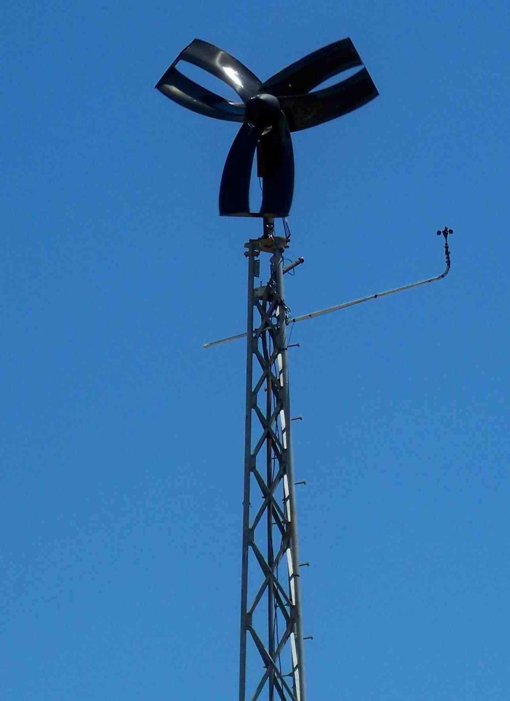
4 12.Hi-Q #61 Installation at West Texas A&M University Introduction Installation West Texas A&M University Testing IEC Data Interpretation Introduction Normalization Process Data Presentation Comparison Conclusions and Recommendations Conclusions Recommendations References Appendix A Final Task Schedule...A1 Appendix B Final Spending Schedule... B1 Appendix C Final Cost Share Contributions... C2 iv
5 List of Figures Figure 2.1 Coordinate System of the Rotor (Front View)...5 Figure 2.2 Coordinate System of the Rotor (Isometric View)...6 Figure 2.3 Full Rotor Side View...7 Figure 2.4 Detailed Rotor Side Profile (Side View)...8 Figure 2.5 Estimated Maximum Rotor Performance (extracted from Reference 1)...11 Figure 2.6 Front View of 3-Blade Design Tip Separation 1.5 in, Tip Stagger 0.5 in...12 Figure 2.7 Side View of 3-Blade Design Tip Separation 1.5 in, Tip Stagger 0.5 in...12 Figure 2.8 Tilted View of 3-Blade Design Tip Separation 1.5 in, Tip Stagger 0.5 in...13 Figure 2.9 Tilted View of 3-Blade Design with Tip Separation Set to 1.5 in and Tip Stagger 0.5 in...13 Figure 2.10 Front View of 3-Blade Design with Tip Separation Set to 3.0 in and Tip Stagger 0.5 in...13 Figure 2.11 Side View of 3-Blade Design with Tip Separation 3.0 in and Tip Stagger 0.5 in...14 Figure 2.12 Tilted View of 3-Blade Design with Tip Separation Set to 1.5 in and Tip Stagger 1.0 in...14 Figure 2.13 Front View of 3-Blade Design with Tip Separation Set to 1.5 in and Tip Stagger 1.0 in...14 Figure 2.14 Side View of 3-Blade Design with Tip Separation Set to 1.5 in and Tip Stagger 1.0 in...15 Figure 2.15 Front View Original Design with X offset set to 0.25 in...15 Figure 2.16 Side View of Original Design with X offset set to 0.25 in...15 Figure 2.17 Tilted View of Original Design with X offset set to 0.25 in...16 Figure 2.18 Front View of Original Design with Y offset set to 0.15*Diameter, Theta (angle of tip) 75 degrees...16 Figure 2.19 Side View of Original Design with Y offset set to 0.15*Diameter, Theta (angle of tip) 75 degrees...16 Figure 2.20 Tilted View of Original Design with Y offset set to 0.15*Diameter, Theta (angle of tip) 75 degrees...17 Figure 2.21 Front View of Original Design with High DX, Low Theta, and Middle Sections Not Corrected to New Theta...17 Figure 2.22 Side View of Original Design with High DX, Low Theta, and Middle Sections Not Corrected to New Theta...17 Figure 2.23 Tilted View of Original Design with High DX, Low Theta, and Twist Not Corrected to New Theta...18 Figure 2.24 Tilted View of Original Design with DX = 0 and DY = Figure 2.25 Front View of Original Design with DX = 0 and DY = Figure 2.26 Tilted View of Original Design with DX = 0 and DY = Figure 2.27 Bent Triangular Design...19 Figure 2.28 Pressure Contours: Front View...20 Figure 2.29 Pressure Contours: Rear View...20 Figure 2.30 Pressure Contours: Isometric View...21 Figure 2.31 Pressure Contours: Isometric View (2)...21 Figure 2.32 Blade Section Aerodynamics...22 Figure 3.1 The Airfoil Sections on Hi-Q Rotor Planform...27 Figure 3.2 The NACA 0012 Airfoil Profile...31 v
6 Figure 3.3 The NACA 0016 Airfoil Profile...31 Figure 3.4 The S822 Airfoil Profile...31 Figure 3.5 The S823 Airfoil Profile...32 Figure 3.6 The S825 Airfoil Profile...32 Figure 3.7 Effect of Airfoil Selection on the Aerodynamic Performance of the Hi-Q Rotor (c eff = ft, b eff = ft and θ AS1 θ AS2 )...33 Figure 3.8 Effect of Airfoil Section Span, b eff, on the Maximum Attainable Power of the Hi-Q Rotor (c eff = ft and θ AS1 θ AS2 )...34 Figure 3.9 Effect of Airfoil Section Chord, c eff, on the Maximum Attainable Power Coefficient of the Hi-Q Rotor (θ AS1 θ AS2 )...35 Figure 3.10 Effect of Airfoil Section Chord, c eff, on Maximum Attainable Power of Hi-Q Rotor (θ AS1 θ AS2 )...35 Figure 3.11 Aerodynamic Performance of 5 Hi-Q Rotor Designs with Highest Maximum Attainable Power (c eff = ft, b eff = ft and θ AS1 θ AS2 )...39 Figure 3.12 The non-airfoil Sections on Hi-Q Rotor Planform...39 Figure 3.13 Rotor Surface Pressure Distribution of Design 50 (Viewed from front of Rotor)...41 Figure 3.14 Rotor Surface Pressure Distribution of Design 50 (Viewed from back of Rotor)...42 Figure 3.15 The Hi-Q Rotor Geometric Characteristic on Rotor Blade Interference Effect (Viewed from the front of the Rotor)...44 Figure 3.16 The Velocity Vector Plot of Design 50 at the outboard station of Airfoil Section 1 and Airfoil Section Figure 4.1 The Hi-Q Rotor Planform of Triangular Configuration (R rotor = 8 inches)...50 Figure 4.2 Hi-Q Rotor #61 3-Bladed Configuration (R rotor = 8 inches)...51 Figure 4.3 Kyle Wetzel Rotor 2-Bladed HAWT Configuration (R rotor = 8 inches)...51 Figure 4.4 Side View of Endplate 1 (Default Size)...52 Figure 4.5 Side View of Endplate Figure 4.6 Side View of Endplate Figure 4.7 Rotor Design # 56 without Endplate...53 Figure 4.8 Rotor Design # 56 with Endplate 1 (Default Size)...54 Figure 4.9 Rotor Design # 56 with Endplate Figure 4.10 Rotor Design # 56 with Endplate Figure 4.11 Rotor Design # Figure 4.12 Rotor Design # Figure 4.13 Rotor Design # Figure 4.14 Rotor Design # Figure 4.15 Rotor Design # Figure 4.16 NACA 0012 Airfoil Profile on Rotor Design # Figure 4.17 S822 Airfoil Profile on Rotor Design # Figure 4.18 S823 Airfoil Profile on Rotor Design # Figure 4.19 S825 Airfoil Profile on Rotor Designs #50 and # Figure 4.20 Aerodynamic Power of Rotor Design # Figure 4.21 Aerodynamic Power of Rotor Design # Figure 4.22 Aerodynamic Power of Rotor Design # Figure 4.23 Aerodynamic Power of Rotor Design # Figure 4.24 Aerodynamic Power of Rotor Design # Figure 4.25 The Maximum Attainable P aerodynamic of Five Tested Rotors...64 Figure 4.26 Rotor KW...65 vi
7 Figure 4.27 Aerodynamic Power of Rotor KW...66 Figure 4.28 Published Technical Specification of Bergey XL.1 HAWT (Reference 2)...67 Figure 4.29 Published Technical Specification of Bergey XL.1 HAWT (Reference 2)...67 Figure 4.30 Power Coefficient of Rotor Design # Figure 4.31 Power Coefficient of Rotor Design # Figure 4.32 Power Coefficient of Rotor Design # Figure 4.33 Power Coefficient of Rotor Design # Figure 4.34 Power Coefficient of Rotor Design # Figure 4.35 Rotor Power Coefficient of Bergey XL. and 1 HAWT 5 Hi-Q Rotors...72 Figure 5.1 Modular Design 61 from Phase I...74 Figure 5.2 Modular Conventional HAWT Bergey XL.1(Scaled)...75 Figure 5.3 Modular Conventional HAWT used in Phase I...75 Figure 5.4 Full Scale Conventional HAWT Bergey XL Figure 5.5 Conventional HAWT Bergey XL.1 Generator...77 Figure 5.6 Parametric 3D CAD Model of the Bergey XL Figure 5.7 Bergey XL.1 Blade...78 Figure 5.8 Generator Calibration Stand...79 Figure 5.9 Resistor Box...79 Figure 5.10 KU Small Wind Tunnel...80 Figure 6.1 Modular Conventional HAWT: Wetzel Rotor...81 Figure 6.2 Modular Hi-Q Design # Figure 6.3 Modular Hi-Q Design # Figure 6.4 Modular Conventional HAWT: Bergey XL Figure 6.5 C p of Hi-Q Design # 61 (2-Bladed Pair) with No Endplates...85 Figure 6.6 C p of Hi-Q Design # 61 (2-Bladed Pair) with Endplates...85 Figure 6.7 C p of Hi-Q Design # 61 of 2-Bladed Pair (Endplates vs. no Endplates)...86 Figure 6.8 C p of Hi-Q Design # 61 (3-Bladed Pair) with No Endplates...87 Figure 6.9 C p of Hi-Q Design # 61 (3-Bladed Pair) with Endplates...87 Figure 6.10 C p of Hi-Q Design # 61 3-Bladed Pair (Endplates vs. no Endplates)...88 Figure 6.11 C p of Hi-Q Design # 61 with Endplates (2 Bladed Pair vs. 3 Bladed Pair)...89 Figure 6.12 C p of Hi-Q Design # 61 vs. Hi-Q Design # 62, with No Endplates (2 Bladed Pair).90 Figure 6.13 C p of Hi-Q Design # 61 vs. Hi-Q Design # 62, with no Endplates (3 Bladed Pair).90 Figure 6.14 C p of Hi-Q Design # 61 with no Endplates (3 Bladed Fwd vs. 3 Bladed Aft and 3 Bladed Pair)...91 Figure 6.15 Wind Mill Rotational Speed (No Generator Load) of Different Wind Mills Figure Bladed Hi-Q Design # 61 Rotor with Modified End Plates...96 Figure Bladed Bergey Rotor...97 Figure Bladed Kyle Wetzel Rotor...98 Figure 7.4 C p of the Three Tested Rotors...99 Figure 8.1 Coordinate Systems of A Single Rotor Blade Figure 8.2 Surface Designation on the Forward Swept Blade Figure 8.3 Surface Designation on the Aft Swept Blade Figure 9.1 Finite Element Model Figure 9.2 LTM 25ST 2x2 Twill: Quasi-isotropic (Reference 10) Figure 9.3 AISI 4130 Steel (Reference 11) Figure T351 Aluminum (Reference 11) Figure T651 Aluminum (Reference 11) vii
8 Figure 9.6 Blade Skins, Leading Edge Figure 9.7 Blade Skins in the region of the Ribs Figure 9.8 Blade Trailing Edge Figure 9.9 End Cap Figure 9.10 Ply Orientation Reference on Blade Skins, Leading and Trailing Edges Figure 9.11 Ply Orientation Reference on End Cap Figure 9.12 Rib Geometry Figure 9.13 Spar Geometry Figure 9.14 Static Load, Blade Skins, Composite Max. Failure Index (0.138) Figure 9.15 Dynamic Load, Blade Skins, Composite Max. Failure Index (0.097) Figure 9.16 Static Load, Blade-Rib Skins, Composite Max. Failure Index (0.026) Figure 9.17 Dynamic Load, Blade-Rib Skins, Composite Max. Failure Index (0.044) Figure 9.18 Static Load, Blade Trailing Edge Skin, Composite Max. Failure Index (0.273) Figure 9.19 Dynamic Load, Blade Trailing Edge Skin, Composite Max. Failure Index (0.118) Figure 9.20 Static Load, Blade Leading Edge Skin, Composite Max. Failure Index (0.128) Figure 9.21 Dynamic Load, Blade Leading Edge Skin, Composite Max. Failure Index (0.064) Figure 9.22 Static Load, End Cap, Composite Max. Failure Index (0.264) Figure 9.23 Dynamic Load, End Cap, Composite Max. Failure Index (0.221) Figure 9.24 Static Load, Blade Skins, Max. Principal Stress ( σ 1 max =6,065 psi) Figure 9.25 Static Load, Blade Skins, Min. Principal Stress ( σ 1 min =-6,095 psi) Figure 9.26 Static Load, Blade Skins, Max. Shear Stress ( τ 12 =560 psi) Figure 9.27 Dynamic Load, Blade-Rib Skins, Max. Principal Stress ( σ 1 max =3,251 psi) Figure 9.28 Dynamic Load, Blade-Rib Skins, Min. Principal Stress ( σ 1 min =-1,706 psi) Figure 9.29 Dynamic Load, Blade-Rib Skins, Max. Shear Stress ( τ 12 =177 psi) Figure 9.30 Static Load, Blade Trailing Edge Skin, Max. Principal Stress ( σ 1 max =13,419 psi) Figure 9.31 Static Load, Blade Trailing Edge Skin, Min. Principal Stress ( σ 1 min =-3,878 psi)120 Figure 9.32 Static Load, Blade Trailing Edge Skin, Max. Shear Stress ( τ 12 =1,784 psi) Figure 9.33 Static Load, Blade Leading Edge Skin, Max. Principal Stress ( σ 1 max =4,852 psi) Figure 9.34 Static Load, Blade Leading Edge Skin, Min. Principal Stress ( σ 1 min =-5,686 psi)122 Figure 9.35 Static Load, Blade Leading Edge Skin, Max. Shear Stress ( τ 12 =623 psi) Figure 9.36 Static Load, End Cap, Max. Principal Stress ( σ 1 max =11,941 psi) Figure 9.37 Static Load, End Cap, Min. Principal Stress ( σ 1 min =-12,200 psi) Figure 9.38 Static Load, End Cap, Max. Shear Stress ( τ 12 =803 psi) Figure 9.39 Dynamic Load, Ribs, Max. Principal Stress ( σ 1 max =31,130 psi) Figure 9.40 Dynamic Load, Ribs, Min. Principal Stress ( σ 1 min =-20,786 psi) Figure 9.41 Dynamic Load, Ribs, Max. Shear Stress ( τ max =13,202 psi) viii
9 Figure 9.42 Static Load, Spars, Max. Principal Stress ( σ 1 max =46,724 psi) Figure 9.43 Static Load, Spars, Min. Principal Stress ( σ 1 min =-41,974 psi) Figure 9.44 Static Load, Spars, Max. Shear Stress ( τ max =16,763 psi) Figure 9.45 Static Load, Spar Inserts, Max. Principal Stress ( σ 1 max =10,300 psi) Figure 9.46 Static Load, Spar Inserts, Min. Principal Stress ( σ 1 min =-9,228 psi) Figure 9.47 Static Load, Spar Inserts, Max. Shear Stress ( τ max =4,863 psi) Figure 10.1 Forces and Moments Acting on the Bergey XL.1 (Top View) Figure 10.2 Forces and Moments Acting on the Bergey XL.1 (Back View) Figure 10.3 Bergey XL.1 Tail Section (Side View) Figure 10.4 Moments about the Tower Hinge and the Tail Hinge (Top View) Figure 10.5 Change in Hi-Q Design #61 Rotor Thrust Coefficient as function of Tip Speed Ratio Figure 10.6 Isometric View of the New Vertical Tail Fin (Tail Fin #8) Figure 11.1 Tail Pivot Pin Installation Figure 11.2 Blade Bolt Installation Figure 11.3 Blade Installation Figure 11.4 Blade Hardware Stacking Figure 11.5 Spinner Installation Figure 12.1 Design #61 Assembly Figure 12.2 Bergey XL.1 Assembly Figure 12.3 Instrumentation Figure 13.1 Bergey XL.1 Test Data - Normalized Average Power vs. Bin Wind Speed Figure 13.2 Bergey XL.1 Power Coefficient Figure 13.3 Hi-Q #61 Test Data - Normalized Average Power vs. Bin Wind Speed Figure 13.4 Hi-Q #61Power Coefficient Figure 13.5 Power Curve Comparison ix
10 List of Tables Table 3.1 Geometric Characteristics of the 60 Hi-Q Rotor Designs...29 Table 3.2 Basic Characteristics of the 5 Selected Airfoils...32 Table 3.3 Effect of Rotor Airfoil Section Pitch Distribution on the Maximum Attainable Power of the Hi-Q Rotor (c eff = ft and b eff = ft)...38 Table 3.4 Five Hi-Q Rotor Designs with the Highest Maximum Attainable Power...38 Table 3.5 Ratio of Rotor Central Fairing Torque to Rotor Airfoil Section Torque of Design Table 3.6 Ratio of Rotor Side Fairing Torque to Rotor Airfoil Section Torque of Design Table 3.7 Comparison of Rotor Tip Speed Ratio at which the Maximum Attainable Power is achieved, between Analytical and Computational Model...46 Table 4.1 Geometric Characteristics of Tested Rotors...52 Table 4.2 Effect of Endplate on the Aerodynamic Performance of Rotor Design # Table 4.3 Rotor Design #56 Rotational Speed (at maximum Aerodynamic Power)...56 Table 4.4 The Maximum Attainable P aerodynamic of Five Tested Rotors...63 Table 4.5 Rotational Speed Corresponding to Maximum Attainable P aerodynamic...63 Table 4.6 Rotor Tip Speed Ratio Corresponding to Maximum Attainable P aerodynamic...63 Table 4.7 Performance of Bergey XL Table 4.8 Maximum Attainable Power Coefficient of 5 tested Hi-Q Rotors...72 Table 5.1 Accura 55 Properties...76 Table 6.1 Geometric Characteristics of Tested Rotor Model Configuration...84 Table 6.2 Wind Mill Rotational Speed (No Generator Load) as Function of Wind Speed...92 Table 7.1 Geometric Characteristics of Tested Rotor Model Configuration...95 Table 8.1 Static Aerodynamic Loads (Inboard Surfaces) at 52.5 m/s Table 8.2 Static Aerodynamic Loads (Outboard Surfaces) at 52.5 m/s Table 9.1 Summary of Stresses Table 9.2 Summary of Safety Factors Table 10.1 Geometric and Aerodynamic Characteristics of the 9 Vertical Tail Fins x
11 List of Symbols and Acronyms Symbol Description Unit A Wind Turbine Rotor Swept Area m 2 A.C. Aerodynamic Center --- ASB Aft Swept Blade --- B Barometric Pressure Pa BR Blockage Ratio --- b tail fin Span of the Vertical Tail Fin m c rotor Section Chord ft C D Drag Coefficient ~ C L Lift Coefficient ~ C Q Torque Coefficient ~ CFD Computational Fluid Dynamics --- C.G. Center of Gravity --- C p Aerodynamic Power Coefficient --- C p,i Power Coefficient in bin i --- C T rotor Hi-Q Hi-Q Design #61 Rotor Thrust Coefficient --- c tail fin Chord of the Vertical Tail Fin m c tail rudder Chord of the Vertical Tail Fin Rudder m C y tail fin Aerodynamic Side Force Coefficient of the Vertical Tail Fin --- D Diameter ft D rotor Rotor Diameter m D s Support Diameter ft DX Section Depth ft DY Section Height ft E Young's Modulus ksi F Force lb FE Finite Element --- FSB Forward Swept Blade --- xi
12 F y tail fin Aerodynamic Side Force of the Vertical Tail Fin N H Height of the Wind Tunnel Test Section ft HAWT Horizontal Axis Wind Turbine --- Hi-Q Hi-Q Design #61 Rotor --- IEC International Electrotechnical Commission --- I xx Rotor Moment of Inertia about X-axis (axis of rotation) slug-ft 2 L.E. Leading Edge --- l s Support Length ft l unfolded Rotor Length Unfolded ft M tail hinge Moments Acting About the Tail Hinge N-m M tail hinge friction The Static Friction in the Tail Hinge N-m M tower hinge Moments Acting About the Tower Hinge N-m N (or N rotor ) Numbers of Rotor Blades --- n Rotor Revolution per Second rps N i Number of 10 minute Data Sets in bin i --- P Rotor Power W P 10 min Measured Power Average over 10 minutes W P i Normalized and Averaged Power Output for each bin W P n,i,j Normalized Power Output of data set j in bin i W P n Normalized Power Output W P w Vapor Pressure Pa Q Rotor Torque ft-lbf R Rotor Blade Radius ft R 0 Gas Constant of Dry Air Jkg -1 k -1 RPM Rotor Revolution Speed rpm r t Transition Radius degree R W Gas Constant of Water Vapor Jkg -1 k -1 S blade Rotor Blade Area m 2 S rotor Rotor Swept Area m 2 xii
13 S tail fin Tail Fin Surface Area m 2 T Absolute Temperature K T rotor blade Thrust Force of the Rotor Blade N TSR Tip Speed Ratio --- t Blade Thickness in t h Hub Thickness ft V i Normalized and Averaged Wind Speed for each bin m/s V n,i,j Normalized Wind Speed of data set j in bin i m/s V wind Wind Velocity m/s W Width of the Wind Tunnel Test Section ft W tail Weight of the Tail N W tail boom Weight of the Tail Boom N W tail fin Weight of the Tail Fin N w rotor Rotor Blade Width ft X LE tail fin (Longitudinal) Distance from Origin to Tail Fin L.E. Location m X rotor blade (Longitudinal) Distance from Origin to Rotor Blade m X tail CG (Longitudinal) Distance from Origin to Tail C.G. Location m X tail fin side force (Longitudinal) Distance from Origin to Tail Fin A.C. Location m Symbol Description Unit X tail hinge (Longitudinal) Distance from Origin to Tail Hinge m X tower hinge (Longitudinal) Distance from Origin to Tower Hinge m Y rotor blade (Lateral) Distance from Origin to Rotor Blade m Y tower hinge (Lateral) Distance from Origin to Tower Hinge m φ Relative Humidity --- Λ c / 4 Quarter chord sweep deg λ Tip Speed Ratio --- θ Angles between the Tail Boom and the Horizontal Plane deg ρ Air Density kg/m 3 xiii
14 ρ 0 Reference Air Density kg/m 3 ρ 10 min Measured Air Density Average over 10 minutes kg/m 3 σ rotor Rotor Solidity Ratio --- σ Stress (Yield) psi σ rotor Rotor Solidity Ratio --- τ 12 Stress (Shear) psi ω Rotational Speed rad/s ψ Angles between the Tail Boom and the Vertical Plane deg Subscripts Description 1 Principal 10 min 10 minute Average aft Aft Blade f Flexure fwd Forward Blade i Bin j Set L Landing LE Leading edge LOF Lift-off max Maximum min Minimum n Normalized p Power paired Both Forward and Aft Blade present rotor Rotor Blade t tension test-section Wind Tunnel Test Section v Vertical tail wind mill Wind Turbine xiv
15 xv
16 1. Executive Summary The original investigation (Technology Readiness Level 1-3) of the Hi-Q Rotor, undertaken with help from a PIER Grant provided by the State of California, was completed August In September of 2006, we began optimizing the Rotor design for a full-scale rotor and field test investigation with the Department of Energy. (Technology Readiness Level 4-7) From Wind Tunnel Testing to Field Testing. The project objective for this stage of investigation, under DOE Award DE-FG36-06GO16046, was to optimize the performance of the Hi-Q Rotor which was found to be efficient and advantageous over state-of-the-art turbines for collecting wind energy in low wind conditions. The Hi-Q Rotor is a new kind of rotor targeted for harvesting wind in Class 2, 3, and 4 sites, and has application in areas that are closer to cities, or load centers. An advantage of the Hi-Q Rotor is that the rotor has non-conventional blade tips and uniquely organizes wind flow, producing less turbulence (vortices), and is quieter than standard wind turbine blades which is critical to the low-wind populated urban sites. The goal for the project was to improve the current design by building a series of theoretical and numeric models (iterations), and composite prototypes to determine a best of class device. From this investigation, an optimized design, the Hi-Q Rotor #61, was determined and an 8-foot diameter, full-scale rotor was built and mounted using a Bergey LX-1 generator and furling system which were adapted to support the rotor. The Hi-Q Rotor was then tested side-by-side against the state-of-the-art Bergey XL-1 at the Alternative Energy Institute s Wind Test Center at West Texas State University for six weeks, and real time measurements of power generated were collected and compared. Conclusions Based on the data collected, the results of our first full-scale prototype wind turbine proved that higher energy can be captured at lower wind speeds with the new Hi-Q Rotor. The Hi-Q Wind Turbine is more productive than the Bergey from 6 m/s to 8 m/s, making it ideal in Class 3, 4, and 5 wind sites. 1
17 Early wind tunnel testing showed that the cut-in-speed of the Hi-Q rotor is much lower than a conventional tested HAWT (Horizontal Axis Wind Turbine) enabling the Hi-Q Wind Turbine to begin collecting energy before a conventional HAWT has started spinning. Also, torque at low wind speeds for the Hi-Q Wind Turbine is higher than the tested conventional HAWT and enabled the wind turbine to generate power at lower wind speeds. Looking at the data collected for the two turbines, it is observed that the Bergey XL.1 is more productive at 9 m/s and up, making it a better choice for Class 6 and 7 wind sites. HOWEVER, the sudden decrease in power output of the new Hi-Q Rotor at wind speeds of 8 m/s and above is attributed to the furling of the tail boom. By improving the furling system, customizing it for low wind speed, it is likely that there will be an increase in the normalized average power of the Hi-Q Wind Turbine at wind speeds above 8 m/s. Even though the maximum output of the Hi-Q Rotor is less than the Bergey, the Hi-Q Rotor is almost 15% more productive at 6-7 m/s. Even with a poorly functioning generator, significant improvements over the standard Bergey XL.1 were observed at these low wind speeds, The final results in this first full scale prototype confirm our contention that the Hi-Q Rotor design is ideal for harvesting wind in low wind sites, Class 2, 3, 4, and 5, and has application in the critical and heretofore untapped areas that are closer to cities, load centers, and may even be used directly in urban areas. The additional advantage of the Hi-Q Rotor s non-conventional blade tips, which eliminates most air turbulence, is noise reduction which makes it doubly ideal for populated urban areas. Recommendations Hi-Q Products recommends one final stage of development to take the Hi-Q Rotor through Technology Readiness Levels 8-9. During this stage of development, the rotor will be redesigned to further increase efficiency, match the rotor to a more suitable generator, and lower the cost of 2
18 manufacturing by redesigning the structure to allow for production in larger quantities at lower cost. Before taking the rotor to market and commercialization, it is necessary to further optimize the performance before by finding a better generator, one more suitable for lower wind speeds and rpms should be used in all future testing. Also, the autofurling system for the Hi-Q Rotor needs adjustment and the Bergey XL.1 settings should not be used. It is recommended to further experiment with the proper hinge locations and fin sizes to obtain the optimal settings for the autofurling system. DARcorporation, Hi-Q Products design and research team, recommends further optimizing the blade shapes in conjunction with cheaper manufacturing processes to make construction of the blades more cost effective. The redesigned rotor will be tested first in the wind tunnel to increase efficiency. It is expected that more slender blades with a different endplate/endcap can be designed to improve rotor efficiency. Slender blades will lower the cost of materials too. Several generators will be spec d out, preferably in the 3-5KW range which is a more suitable power range for powering houses. The generators will be calibrated and the generator with peak performance in the rpm range will be chosen. The blade design will be adjusted in such a way that it will operate at this optimum rpm range. Matching the aerodynamic design of the blades to the generator peak efficiency will result in an optimal operating low wind speed turbine. The design will be perfected using the DAR developed Blade Element Method (BEM) software and CFD tools. Several scale models of the designs will be tested in the wind tunnel to select to best design. Once the best design is chosen, full scale design will proceed. Loads will be determined using CFD analysis. The rotor will be designed in carbon fiber composites. Where possible the aluminum parts and steel shafts of the full size rotor will be replaced with composites. The generator attachment and rotor hub will be designed from scratch. A new autofurling system will be specifically designed for this rotor instead of reusing an existing design. The design will be manufactured by DARcorporation and installed at West Texas A&M University for a period of three months. During testing the power curves will be established for the full scale rotor and generator combination. This phase of development will include the 3
19 commercial market validation of the technology and prepares the foundation for production preparation. Impact of the Technology The potential impact of this fully developed technology will be the expansion and proliferation of energy renewal into the heretofore untapped Class 2, 3, 4, and 5 Wind Sites, or the large underutilized sites where the wind speed is broken by physical features such as mountains, buildings, and trees. Market estimates by 2011, if low wind speed technology can be developed are well above: 13 million homes, 675,000 commercial buildings, 250,000 public facilities. Estimated commercial exploitation of the Hi-Q Rotor show potential increase in U.S. energy gained through the clean, renewable wind energy found in low and very low wind speed sites. This new energy source would greatly impact greenhouse emissions as well as the public sector s growing energy demands. 4

20 2. Phase I Technical Progress Report 2.1 Nomenclature This section presents the primary variables used in designing the rotor CAD model. The coordinate system of the model is shown in Figure 2.1 and Figure 2.2, with the X-axis being the axis of rotation. The rotor is to have a fixed diameter of 1.5 ft. Asides from it, the rotor model is parametrically controlled by the rotor side profile, shown in Figure 2.3. D 60 deg Y Z 60 deg 60 deg w rotor c rotor 60 deg 30 deg Figure 2.1 Coordinate System of the Rotor (Front View) 5

21 Y Z X Figure 2.2 Coordinate System of the Rotor (Isometric View) 6
22 Spinner Side Profile Figure 2.3 Full Rotor Side View 7
 Control Point 2 (+DX, - DY, 0.5D) It is observed in Figure 2.")
23 θ Control Point 1 (-DX, + DY, 0.5D) c rotor +DY X Side Profile Central Control Point (0, 0, 0.5D) r t -DX +DX X -DY c rotor Figure 2.4 Detailed Rotor Side Profile (Side View) Control Point 2 (+DX, - DY, 0.5D) It is observed in Figure 2.4 that the two control points are positioned relative to the side profile central control point (0, 0, 0.5D). The Coordinates of the two control points are (-DX, +DY, 0.5D) & (+DX, -DY, 0.5D). 8
24 Based on Figure 2.1, it is observed that the width of the rotor blade (w blade ), is a function of the rotor section chord (c rotor ). o w rotor = cos(30 ) c rotor where: c rotor is a function of the section height (DY) and section angle (θ). Based on Figure 2.4, the rotor section chord (c rotor ) is defined as: c rotor DY = sin( θ ) Subsequently: w blade can be expressed as: DY o w rotor = cos(30 ) sin( θ ) If the entire rotor blade, with a certain blade thickness, t and blade width, w rotor is to be unfolded to form a straight sheet, then its total length is defined as the rotor unfolded length, l unfolded. With a fixed rotor diameter of 1.5 ft, l unfolded is a function of DX, DY, θ, and r t. For example: DX = 0 DY = 20% of Rotor diameter = ft θ = 82.5 degree r t = ft t = ft (0.060 in) DY/D o 0.20 o w rotor/d= cos(30 ) = cos(30 ) = sin( θ ) o sin(82.5 ) w /D = w rotor rotor = ft 9
25 From the CAD model, it is found that: l /D = unfolded l = ft unfolded The methodology of analyzing the aerodynamic performance of any rotor design is as follows: For any particular rotor design at a given wind speed, a series of CFD analyses on different rotational speeds (or rotor RPM) is carried out. The power generation capability (power coefficient, C p ), of the rotor design, as a function of the rotor tip speed ratio, λ, is plotted. The rotor tip speed ratio is defined as follows: λ = 1 D Ω 2 V The rotor power coefficient is defined as: C P = ρn D p 3 5 RPM where: n = 60 P = 2π Q A typical performance estimate based on blade element momentum technique (BEM) on a horizontal axis wind turbine (HAWT) rotor is documented in Reference 1. 10
26 (C D /C L ) min = (C D /C L ) min = Figure 2.5 Estimated Maximum Rotor Performance (extracted from Reference Error! Reference source not found.) According to Reference Error! Reference source not found., the red curve in Error! Reference source not found. represents a realistic estimate of a conventional HAWT rotor power generation capability. The main objective of the project is to computationally analyze different rotor designs power generation capability and compare the results with the above theoretical estimates The family of rotors has the following designation: HIQ mc x mc ac (t/c) max x (t/c) max R LE /C φ TE DX/D DY/D C/D r t /D θ mc: x mc : (t/c) max : x (t/c) max R LE /C: Maximum camber of the rotor airfoil in percent of chord Location of maximum camber in percent of the chord from the leading edge Maximum thickness in percent of chord Location of maximum thickness in percent chord from the leading edge Leading edge radius in percent chord 11
27 φ TE : Trailing edge angle in degrees DX/D: Position of rotor side profile control point in X-axis with respect to the side profile central control point in percent of rotor diameter DY/D: Position of rotor side profile control point in Y-axis with respect to the side profile central control point in percent of rotor diameter C/D: r t /D: Chord in percent of rotor diameter Tip transition radius in percent diameter θ: Rotor section angle in degrees 2.2 CAD Models Figure 2.6 Front View of 3-Blade Design Tip Separation 1.5 in, Tip Stagger 0.5 in Figure 2.7 Side View of 3-Blade Design Tip Separation 1.5 in, Tip Stagger 0.5 in 12

28 Figure 2.8 Tilted View of 3-Blade Design Tip Separation 1.5 in, Tip Stagger 0.5 in Figure 2.9 Tilted View of 3-Blade Design with Tip Separation Set to 1.5 in and Tip Stagger 0.5 in Figure 2.10 Front View of 3-Blade Design with Tip Separation Set to 3.0 in and Tip Stagger 0.5 in 13

29 Figure 2.11 Side View of 3-Blade Design with Tip Separation 3.0 in and Tip Stagger 0.5 in Figure 2.12 Tilted View of 3-Blade Design with Tip Separation Set to 1.5 in and Tip Stagger 1.0 in Figure 2.13 Front View of 3-Blade Design with Tip Separation Set to 1.5 in and Tip Stagger 1.0 in 14
30 Figure 2.14 Side View of 3-Blade Design with Tip Separation Set to 1.5 in and Tip Stagger 1.0 in Figure 2.15 Front View Original Design with X offset set to 0.25 in Figure 2.16 Side View of Original Design with X offset set to 0.25 in 15


31 Figure 2.17 Tilted View of Original Design with X offset set to 0.25 in Figure 2.18 Front View of Original Design with Y offset set to 0.15*Diameter, Theta (angle of tip) 75 degrees Figure 2.19 Side View of Original Design with Y offset set to 0.15*Diameter, Theta (angle of tip) 75 degrees 16


32 Figure 2.20 Tilted View of Original Design with Y offset set to 0.15*Diameter, Theta (angle of tip) 75 degrees Figure 2.21 Front View of Original Design with High DX, Low Theta, and Middle Sections Not Corrected to New Theta Figure 2.22 Side View of Original Design with High DX, Low Theta, and Middle Sections Not Corrected to New Theta 17


33 Figure 2.23 Tilted View of Original Design with High DX, Low Theta, and Twist Not Corrected to New Theta Figure 2.24 Tilted View of Original Design with DX = 0 and DY = 3.6 Figure 2.25 Front View of Original Design with DX = 0 and DY =


34 Figure 2.26 Tilted View of Original Design with DX = 0 and DY = 4.5 Figure 2.27 Bent Triangular Design 2.3 Initial CFD Analysis Using Blue Ridge Numerics CFDesign and the models created in Unigraphics NX, a new method has been developed to speed up CFD analysis. Analysis that used to take 100 hours are now cut down to about 4 hours. The following figures show pressure distributions over the surface of the rotor. These pressure distributions are used to analyze which part of the rotor makes the rotor spin and thus generate power. 19

35 Figure 2.28 Pressure Contours: Front View Figure 2.29 Pressure Contours: Rear View 20


36 Figure 2.30 Pressure Contours: Isometric View Figure 2.31 Pressure Contours: Isometric View (2) 21
37 2.4 Blade Element Theory This section presents the equations used for the Hi-Q rotor design using blade element momentum technique. The equations are currently programmed in a MathCAD filke and are being transferred to a program written in Borland (CodeGear) Delphi so that batch jobs can be run. The coordinate system and variables are defined in Figure Figure 2.32 Blade Section Aerodynamics The first step in designing the Hi-Q rotor is the airfoil selection. For this the airfoil lift curve slope c lα, the airfoil zero angle of attack lift coefficient c l 0, and the drag trendline c d are to be defined. 22
38 The rotor sectional lift and drag coefficients at a blade radial location is defined as follows: c = c + c α α l l0 l Where, cl α & c l 0 are adjusted for Mach number effect (Prandtl-Glauert correction). c lα c = lα@ M = 0 1 M 2 & c c M = 0 l = M d ( α ) ( α ) c = f = c d Where c d (as a function of angle of attack) is adjusted for Mach and Reynolds number effect The relative speed of wind at the rotor is defined as follows: U rel ( 1 a) U = sinφ Where, φ = θ p + α And θ p = θt + θ p,0 θ p = Section pitch angle θ T = Section twist angle θ p,0 = Blade pitch angle at the tip Note that the rotor blade spanwise pitch distribution, θ = f (r), is a user defined input parameter. The airfoil sectional dimensional lift and drag per unit span (radius) are expressed as: 23
39 1 2 dfl = cl ρurelc dfd = cd ρurelc 2 Note that the rotor blade airfoil chord, c = f (r), is a user defined input parameter. Resolving the sectional aerodynamic forces normal and parallel to the disk plane gives df = df cosφ + df N L D sinφ df = df sinφ df T L D cosφ For a rotor with B number of blades, the total normal force (or thrust) is given by 1 2 dfn = ρurel B( cl cosφ + cd sinφ ) cdr 2 And the elemental differential torque due to the tangential force operating at a distance, r, from the center is given by dq = Br df T or 1 2 dq = ρurel B( cl sinφ cd cosφ ) crdr 2 Equations (5-8) and (5-10) can be simplified further as follows 2 ( 1 a) 2 U dfn = σ πρ ( c cos sin ) 2 l φ + cd φ rdr sin φ 24
40 2 ( 1 a) 2 U 2 dq = σ πρ ( c sin cos ) 2 l φ cd φ r dr sin φ Where, Bc σ =, is defined as the local solidity. 2π r The elemental thrust and power coefficients are as follows: 2 ( 1 a ) ( cosφ sinφ ) σ dct = c 2 l + cd dr sin φ dc P = Ω dc Q The overall rotor thrust and power can be described as: C T 1 = 0 dc dr T λ λ 8 3 c ( 1 ) 1 d CP = dc p dλr = cot 2 λr a a φd λr c λ λ l h λ h Where, λ h is the local tip speed ratio at the hub Ωr λr = U a ( 1 ) a a = + + λr 25
41 The numerical integration is performed using the Simpson s rule, which states that: Where: h = (b-a)/n 26
 technique has been developed.")
42 3. Phase I Summary of Aerodynamic Performance of 60 Hi-Q Rotor Designs To help with the design and the analysis of the aerodynamic performance of the Hi-Q wind turbine rotor, an analytical code using the blade-element-momentum (BEM) technique has been developed. Based on the initial concept studies, several important parameters influencing the aerodynamic performance of the Hi-Q rotor have been identified. They include: Airfoil selection Reynolds number (or rotor blade airfoil section chord, c eff ) Rotor blade airfoil section pitch distribution (θ) Rotor blade airfoil section planform area (S eff = c eff * b eff ) The definition of the airfoil section chord and the airfoil sectional planform area is illustrated in Figure 3.1. Outboard Inboard Outboard Airfoil Section 1 Airfoil Section 2 Airfoil Section Chord, c eff Airfoil Section Span, b eff Airfoil Section Planform Area, S eff = c eff * b eff Figure 3.1 The Airfoil Sections on Hi-Q Rotor Planform In the present design stage, 5 different airfoils, 2 different airfoil section chords, 3 different airfoil section planform area, and 2 different airfoil section pitch distributions, are selected, resulting in a matrix with 60 designs. A summary of the geometric characteristics of the 60 Hi-Q rotor designs is listed in 27
43 Table
44 Table 3.1 Geometric Characteristics of the 60 Hi-Q Rotor Designs Design # Airfoil c eff [ft] b eff [ft] 1 NACA Y θ AS1 = θ AS2 θ AS1 θ AS2 2 NACA Y 3 NACA Y 4 NACA Y 5 NACA Y 6 NACA Y 7 NACA Y 8 NACA Y 9 NACA Y 10 NACA Y 11 NACA Y 12 NACA Y 13 NACA Y 14 NACA Y 15 NACA Y 16 NACA Y 17 NACA Y 18 NACA Y 19 NACA Y 20 NACA Y 21 NACA Y 22 NACA Y 23 NACA Y 24 NACA Y 25 S Y 26 S Y 27 S Y 28 S Y 29 S Y 30 S Y 29
45 Table 3.1 (Contd.) Geometric Characteristics of the 60 Hi-Q Rotor Designs Design # Airfoil c eff [ft] b eff [ft] θ AS1 = θ AS2 θ AS1 θ AS2 31 S Y 32 S Y 33 S Y 34 S Y 35 S Y 36 S Y 37 S Y 38 S Y 39 S Y 40 S Y 41 S Y 42 S Y 43 S Y 44 S Y 45 S Y 46 S Y 47 S Y 48 S Y 49 S Y 50 S Y 51 S Y 52 S Y 53 S Y 54 S Y 55 S Y 56 S Y 57 S Y 58 S Y 59 S Y 60 S Y Note: The reader is reminded that θ AS1 = θ AS2 refers to rotor designs with the pitch distribution of the airfoil section 1 being optimized to produce the highest sectional power coefficient, while the pitch distribution of the airfoil section 2 is made equal to those of the airfoil section 1. On 30
46 the other hand, θ AS1 θ AS2 refers to rotor designs with the pitch distribution of the airfoil section 1 and 2 each being optimized separately to produce the highest sectional power coefficient 3.1 Effect of Airfoil Selection Keeping other parameters the same, i.e. c eff = ft, as well as b eff = ft and θ AS1 θ AS2, the effect of airfoil selection on the aerodynamic performance of the Hi-Q rotor is investigated. The basic characteristics of the 5 selected airfoils are summarized in Table 3.2, while the profiles of the 5 selected airfoils are illustrated in Figure 3.2 through Figure 3.6. Figure 3.2 The NACA 0012 Airfoil Profile Figure 3.3 The NACA 0016 Airfoil Profile Figure 3.4 The S822 Airfoil Profile 31
47 Figure 3.5 The S823 Airfoil Profile Figure 3.6 The S825 Airfoil Profile Table 3.2 Basic Characteristics of the 5 Selected Airfoils Thickness Ratio, t/c [%] Camber [~] Leading Edge Radius, r LE [~] NACA NACA S S S The aerodynamic performance of the 5 rotor designs, expressed in terms of power coefficient vs. rotor tip speed ratio, Cp vs. λ, is shown in Figure
48 Power Coefficient, Cp [~] NACA 0012 NACA 0016 S822 S823 S Tip Speed Ratio, λ [~] Figure 3.7 Effect of Airfoil Selection on the Aerodynamic Performance of the Hi-Q Rotor (c eff = ft, b eff = ft and θ AS1 θ AS2 ) As observed in Figure 3.7, with everything else being kept the same, the Hi-Q rotor with the S825 airfoil, has a maximum attainable power coefficient of , compared to the rotor with the NACA 0012 airfoil of In other words, the difference in maximum attainable power coefficient among the 5 rotors (of different airfoil selection), is 4.1%. 3.2 Effect of Airfoil Section Planform Area (or b eff ) Keeping other parameters the same, i.e. c eff = ft and θ AS1 θ AS2, the effect of airfoil section span, or b eff, on the aerodynamic performance of the Hi-Q rotor is investigated. The 33
49 results of the present study, expressed in terms of a change in maximum attainable power vs. b eff, are shown in Figure Power max [%] NACA NACA 0016 S822 S823 S b eff [ft] Figure 3.8 Effect of Airfoil Section Span, b eff, on the Maximum Attainable Power of the Hi-Q Rotor (c eff = ft and θ AS1 θ AS2 ) From Figure 3.8, it is observed that an increase in the airfoil section span (or airfoil section planform area if the airfoil section chord is kept constant) increases the maximum attainable power of the rotor, and for all practical purposes it can be concluded that the increment in rotor power is independent of airfoil selection. 3.3 Effect of Airfoil Section Chord (or Reynolds Number) Keeping θ AS1 θ AS2, the effect of airfoil section chord, or c eff, on the aerodynamic performance of the Hi-Q rotor is investigated. The results of the present study, expressed in terms of a change in maximum attainable power coefficient vs. c eff, are shown in Figure 3.9, as well as in terms of a change in maximum attainable power vs. c eff in Figure 3.10, respectively. 34
50 CP max [%] NACA 0012 NACA S822 S823 S c eff [ft] Figure 3.9 Effect of Airfoil Section Chord, c eff, on the Maximum Attainable Power Coefficient of the Hi-Q Rotor (θ AS1 θ AS2 ) NACA 0012 NACA 0016 S822 S823 S825 Power max [%] c eff [ft] Figure 3.10 Effect of Airfoil Section Chord, c eff, on Maximum Attainable Power of Hi-Q Rotor (θ AS1 θ AS2 ) 35
51 It is observed in Figure 3.9 that a reduction in airfoil section chord results in a reduction in maximum attainable rotor power coefficient by 1% 3%. However, observing Figure 3.10, it is found that there is an increase in the maximum attainable power by about 18 21%, depending on the airfoil selection. The reader is reminded to pay special attention to this finding. It is logical that a reduction in chord, which is accompanied by a reduction in Reynolds number, increases the airfoil sectional drag coefficient, thus a reduction in the rotor power coefficient as observed in Figure 3.9. However, due to the unique configuration of the Hi-Q rotor, a reduction in the maximum attainable power coefficient does not necessarily indicate a reduction in the maximum attainable rotor power. After reviewing the geometry of the Hi-Q rotor, it is found that due to the unique geometric characteristics of the Hi-Q rotor, compared to a conventional N- bladed horizontal axis wind turbine rotor, HAWT, the standard equation that translates the rotor non-dimensional power coefficient into dimensional rotor power needs to be modified. For a conventional HAWT, the equation that relates the rotor power coefficient to rotor power is as follows: Cp = P 1 3 ρu Arotor 2 Cp = P 1 3 ρu π 2 ( R ) 2 rotor Since both of the airfoil sections on the Hi-Q rotor do not begin from the center of the rotor, the above equation needs to be modified in such a way that the unique geometric characteristics of Hi-Q rotor can be properly reflected. The proper equation should be as follows: P C p = ρu π 2 ( Rrotor _ outboard _ station ) ( Rrotor _ inboard _ station ) 36
52 For airfoil section 1: R rotor_outboard_station = R rotor R rotor_inboard_station < R rotor For airfoil section 2: R rotor_outboard_station > R rotor Note: Refer to Figure 3.1 on the definition of the location of the inboard or the outboard station. It is found that as the airfoil section chord is reduced from ft to ft, the term, 2 2 ( Rrotor _ outboard _ station ) ( Rrotor _ inboard _ station ) increases, and the rate of increase of the term, outgrows the reduction in the maximum attainable rotor power coefficient. When comparing the aerodynamic performance of two Hi-Q rotors of different c eff and b eff, the dimensional maximum attainable power, P max, should be used, over the dimensionless maximum attainable power coefficient, C p max. 3.4 Effect of Airfoil Section Pitch Distribution Keeping other parameters the same, i.e. c eff = ft and b eff = ft, the effect of airfoil section pitch distribution on the aerodynamic performance of the Hi-Q rotor is investigated. The results of the present study are summarized in Table
53 Table 3.3 Effect of Rotor Airfoil Section Pitch Distribution on the Maximum Attainable Power of the Hi-Q Rotor (c eff = ft and b eff = ft) Airfoil θ 1 = θ 2 θ 1 =/ θ 2 D P max [%] NACA NACA S S S From Table 3.3, it is found that having an optimized pitch distribution, one for each airfoil section, certainly helps increasing the aerodynamic performance of the rotor. Out of the 60 Hi-Q rotor designs, the five rotors with the highest maximum attainable power are selected. There are as follows Table 3.4 Five Hi-Q Rotor Designs with the Highest Maximum Attainable Power Design # Airfoil c eff [ft] b eff [ft] θ AS1 θ AS2 P max attainable [W] 50 S Y S Y S Y NACA Y NACA Y Note: For all 60 rotor designs, the wind speed is assumed to be 6.17 m/s (or 12 kts), and the rotor diameter is assumed to be 16 inches. The aerodynamic performance of the 5 rotor designs is shown in Figure
![6.0 5.5 5.0 NACA 0012 NACA 0016 S822 S823 S825 Power, P tot [W] 4.5 4.0 3.5 3.0 2.5 2.0 1.0 1.5 2.0 2.5 3.0 3.5 4.0 4.5 5.0 Tip Speed Ratio, λ [~] Figure 3.](/docs-images/72/67574685/images/54-0.jpg "11 Aerodynamic Performance of 5 Hi-Q Rotor Designs with Highest Maximum Attainable Power (c eff = 0.257 ft, b eff = 0.349 ft and θ AS1 θ AS2 ) The 5 rotors are analyzed computationally.")
54 NACA 0012 NACA 0016 S822 S823 S825 Power, P tot [W] Tip Speed Ratio, λ [~] Figure 3.11 Aerodynamic Performance of 5 Hi-Q Rotor Designs with Highest Maximum Attainable Power (c eff = ft, b eff = ft and θ AS1 θ AS2 ) The 5 rotors are analyzed computationally. Results of the CFD analysis of Design 50, summarized in Table 3.4, are presented. Rotor Side (tip) Fairing Rotor Central Fairing Figure 3.12 The non-airfoil Sections on Hi-Q Rotor Planform 39
55 The primary objectives of analyzing the rotors computationally are: 1. To determine out the effect of the rotor central fairing (shown in Figure 3.12) on the overall aerodynamic performance of the rotor. 2. To find out the effect of the rotor side (tip) fairing (shown in Figure 3.12) on the overall aerodynamic performance of the rotor. 3. To determine the effect of the rotor blade interference on the overall aerodynamic performance of the rotor. CFD analyses are deemed necessary as the above mentioned effects cannot be modeled by the developed analytical code. 3.5 Effect of Rotor Central Fairing The rotor surface pressure distribution of rotor design # 50, at a rotor tip speed ratio of 2.5, is presented in Figure 9a and Figure 9 b. 40

56 Direction of Tangential Velocity Acting on the Central Fairing Direction of Rotation Direction of Oncoming Wind Rotor Central Fairing Figure 3.13 Rotor Surface Pressure Distribution of Design 50 (Viewed from front of Rotor) 41
 As observed in Figure 3.")
57 Direction of Tangential Velocity Acting on the Central Fairing Direction of Rotation Direction of Oncoming Wind Rotor Central Fairing Figure 3.14 Rotor Surface Pressure Distribution of Design 50 (Viewed from back of Rotor) As observed in Figure 3.13, the front surface of the rotor central fairing is covered with high positive pressure (red color). With respect to the direction of the tangential velocity acting on the rotor central fairing, the high positive pressure (at windward side) physically translates to high drag. In other words, the rotor central fairing is producing a (negative) torque which acts against the direction of rotation. 42
58 Observing Figure 3.14, it is found that the back surface of the rotor central fairing is covered with slightly negative pressure (-0.5 Psf < P < 0). With respect to the direction of the tangential velocity, the negative pressure (at leeward side) also translates to drag, thus producing a (negative) torque which acts against the direction of rotation Due to the unique geometric configuration of the Hi-Q rotor, the rotor central fairing can be viewed as a small section of wing which connects the Airfoil Section 1 and the Airfoil Section 2. Subsequently, the twist on the rotor central fairing is controlled by the pitch distribution of the two airfoil sections. Taking a particular rotor design as an example, if the pitch at the inboard station of both airfoil sections (Refer to Figure 3.1) equals zero, then the twist becomes zero, and the drag on the rotor central fairing is minimum. The ratio of rotor central fairing torque to rotor airfoil section torque of Design 50 is summarized in Table 3.5. From Table 3.5, it is found that the resistive (negative) torque induced by the rotor central fairing is around 4 7%, compared to the positive torque generated by the airfoil sections. Table 3.5 Ratio of Rotor Central Fairing Torque to Rotor Airfoil Section Torque of Design 50 Tip Speed Ratio λ [~] RPM τ Central Fairing / τ (AS1 + AS2) [%] Effect of Rotor Side (Tip) Fairing The purpose of the rotor side fairing is to act as a barrier in preventing the high positive (gage) pressure on the front side (pressure side) of the airfoil sections from escaping to the low negative (gage) pressure on the back side (suction side) of the airfoil sections. This is known as the tip loss phenomenon. While the rotor tip fairing improves the airfoil section outboard lift coefficient, thus the aerodynamic performance, its presence on the other hand generates drag and thus produces negative torque. Based on the results of the CFD analyses on Design 50, which are summarized in Table 5, it is found that a significant amount of negative torque is generated due to the presence of the rotor tip fairing, which is about 13 24%, compared to the positive 43
 [%] 2.00 580-13.4 2.25 653-14.8 2.50 725-24.")
59 torque generated by the airfoil sections. In addition, it is also found that the resistive torque increases with the increase in rotor tip speed ratio. Table 3.6 Ratio of Rotor Side Fairing Torque to Rotor Airfoil Section Torque of Design 50 Tip Speed Ratio λ [~] RPM τ Side Fairing / τ (AS1 + AS2) [%] Based on the calculated (negative) torque of the rotor side fairings, summarized in Table 3.6, it is concluded that there is much room for improvement in the rotor overall aerodynamic performance if the rotor side fairing is properly designed. 3.7 Effect of Rotor Blade Interference Outboard Station Outboard Station (LE) Airfoil Section 2 (TE) (LE) Airfoil Section 1 (TE) Inboard Station Inboard Station Direction of Rotation Figure 3.15 The Hi-Q Rotor Geometric Characteristic on Rotor Blade Interference Effect (Viewed from the front of the Rotor) 44


60 The developed analytical code does not take into the account of the rotor blade interference effect. Due to the unique geometric characteristics of the Hi-Q rotor, in reality, shown in Figure 3.15, the rotor blade interference effect does exist. The airflow angles seen by the outboard stations of Airfoil Section 1, to certain degree, is affected by the downwash from the outboard stations of Airfoil Section 2, due to the close proximity. This is graphically illustrated in Figure Outboard Station Outboard Station Airfoil Section 2 Airfoil Section 1 Airfoil Section 2 Profile Airfoil Section 1 Profile Flow field affected by the downwash from the Airfoil Section 2 Figure 3.16 The Velocity Vector Plot of Design 50 at the outboard station of Airfoil Section 1 and Airfoil Section 2 As shown in Figure 3.16, the flow field seen by Airfoil Section 1, which is inside the white circle, is somewhat influenced by the presence of Airfoil Section 2. The consequence is such that the true local inflow angle, as well as the true local angle of attack at the outboard stations of Airfoil Section 1, is different from those predicted analytically. As a result, the tip speed ratio at 45
61 which the rotor is predicted (analytically) to achieve its maximum attainable power, in reality, might not yield a maximum attainable power. Table 3.7 summarizes the predicted rotor tip speed ratio at which the rotor maximum attainable power is obtained, between the analytical and the computational models. From Table 3.7, it is found that the computationally predicted rotor tip speed ratio, at which the rotor achieves its maximum attainable power, is slightly lower than that predicted by the analytical code. Table 3.7 Comparison of Rotor Tip Speed Ratio at which the Maximum Attainable Power is achieved, between Analytical and Computational Model Tip Speed Ratio λ [~] (Analytical) P rotor / max. P rotor [%] (CFD) P rotor / max. P rotor [%] N.A N.A. Note: N.A. stands for Data Not Available 3.8 Conclusions An analytical code is developed to help with designing the Hi-Q rotors. 5 different airfoils, 2 different airfoil section chords, 3 different airfoil section planform area and 2 different airfoil section pitch distribution, are selected, resulting in a matrix with 60 designs. From the 60 rotor designs, Rotor 50, which is the rotor with the S825 airfoil, an effective chord, c eff, of ft, an effective span, b eff, of ft and θ AS1 θ AS2, achieves the highest maximum attainable power. Analyzing the designed rotor computationally reveals the following effects which cannot be identified by the analytical methods: effect of rotor central fairing, side (tip) fairing and the rotor blade interference on the aerodynamic performance of the rotor. 46

 inboard towards the center of the Hi-Q rotor hub, similar to those")
62 The resistive (negative) torque due to the presence of the rotor central and side fairings is not negligible, compared to the positive aerodynamic torque generated by the airfoil sections. The effect of the rotor blade interference is such that the local inflow angle, as well as the local angle of attack at the outboard stations of the Airfoil Section 1 is influenced, resulting in a change in the rotor tip speed ratio at which the rotor is predicted (analytically) to achieve its maximum attainable power. 3.9 Conclusions The geometry of the two airfoils sections of the present Hi-Q rotor configuration can be gradually expanded (radially) inboard towards the center of the Hi-Q rotor hub, similar to those shown in the following figures. With the new configurations, the effective span of the airfoil sections can be further expanded, thus a possible increase in the power performance generation. AS1 AS2 AS1 AS2 AS2 AS1 AS2 AS1 AS1 AS2 AS1 AS2 (a) The Present Configuration (b) Possible Future Configurations 47
")
")
63 AS1 AS2 AS1 AS2 AS2 AS1 AS2 AS1 AS1 AS2 AS1 AS2 (c) Possible Future Configurations (d) Possible Future Configurations 48
64 4. Phase I Aerodynamic Performance of Hi-Q Rotors Tested at KU Wind Tunnel A total of 7 wind turbine rotors, all having a diameter of 16 inches, are tested at the University of Kansas wind tunnel in August and September of Results of the aerodynamic performance of the tested rotors are presented in this memo. The primary objectives of the wind tunnel testing are: To compare the aerodynamic performance among the tested rotors, which are designed based on the developed analytical code that uses the blade-element-momentum (BEM) technique. The results are then compared to two horizontal axis wind turbine (HAWT) rotors, one of which is designed by Dr. Kyle Wetzel and the other is the Bergey XL.1 HAWT. A summary of the geometric characteristics of the seven tested wind turbine rotors is listed in Table 1. The geometric parameters are listed in Figure 4.1 through Figure 4.3. One of the rotors has been tested with different end plates to investigate the effect of end plate size on performance 49

65 R rotor = 8 in Width1 c s Y Z Figure 4.1 The Hi-Q Rotor Planform of Triangular Configuration (R rotor = 8 inches) 50


66 R rotor = 8 in Figure 4.2 Hi-Q Rotor #61 3-Bladed Configuration (R rotor = 8 inches) R rotor = 8 in Figure 4.3 Kyle Wetzel Rotor 2-Bladed HAWT Configuration (R rotor = 8 inches) 51
![Table 4.1 Geometric Characteristics of Tested Rotors Rotor Design # (based on Reference 1) Airfoil Width1 [ft] c s [ft] Configuration 2 NACA 0012 0.222 0.10 26 S822 0.222 0.10 38 S823 0.222 0.10 56 S825 0.](/docs-images/72/67574685/images/67-0.jpg "333 0.10 50 S825 0.222 0.10 61 S825 N.A. N.A. Triangular Hi-Q Configuration Shown in Figure 1 3 Bladed Hi-Q Configuration Shown in Figure 2 2 Bladed HAWT Configuration KW (Kyle Wetzel) Wetzel N.A. N.A. Shown in Figure 3 4.")
67 Table 4.1 Geometric Characteristics of Tested Rotors Rotor Design # (based on Reference 1) Airfoil Width1 [ft] c s [ft] Configuration 2 NACA S S S S S825 N.A. N.A. Triangular Hi-Q Configuration Shown in Figure 1 3 Bladed Hi-Q Configuration Shown in Figure 2 2 Bladed HAWT Configuration KW (Kyle Wetzel) Wetzel N.A. N.A. Shown in Figure Effect of End Plate on Hi-Q Rotor Performance Rotor Design #56 uses three endplates of different sizes to investigate the effect of size of the endplates on the aerodynamic performance of the Hi-Q rotors. The schematics of the three endplates are illustrated in Figure 4.4 through Figure 4.6. Pictures of the three different endplates, when mounted on Rotor Design #56, are shown in Figure 4.7 through Figure Figure 4.4 Side View of Endplate 1 (Default Size) 52


68 Figure 4.5 Side View of Endplate 2 Figure 4.6 Side View of Endplate 3 Figure 4.7 Rotor Design # 56 without Endplate 53


69 Figure 4.8 Rotor Design # 56 with Endplate 1 (Default Size) Figure 4.9 Rotor Design # 56 with Endplate 2 54

70 Figure 4.10 Rotor Design # 56 with Endplate 3 Results of the study of end plate effect are summarized in Table 4.2. Table 4.2 Effect of Endplate on the Aerodynamic Performance of Rotor Design #56 Rotor Design #56 max. Aerodynamic Power, P aerodynamic [W] U = 18 [kts] U = 26 [kts] no Endplate Endplate 1 (Default Size) Endplate Endplate The net measured power is as follows: Pnet = VI where: V is voltage readout [Volt] I is current readout [Amp] 55
71 The voltage and current data are measured while the rotor is spinning. The net power, P net, is the product of the measured voltage and the measured current. P net does not account for the electrical and mechanical losses associated with the generator and bearings and therefore P net does not reflect the aerodynamic power of the Hi-Q rotors. The aerodynamic power of the rotor is represented by P aerodynamic. The following equation describes the relationship between the P net and P aerodynamic. Paerodynamic = Ploss + Pnet where: Ploss is power loss of the generator [W] The rotor rotational speed, expressed in terms of the shaft RPM, corresponding to the maximum P aerodynamic, is summarized in Table 4.3. Table 4.3 Rotor Design #56 Rotational Speed (at maximum Aerodynamic Power) Rotor Design #56 max P aerodynamic U = 18 [kts] U = 26 [kts] no Endplate Endplate 1 (Default Size) Endplate Endplate From Table 4.2 it is found that an increase in the size of the endplate reduces the aerodynamic performance of the rotors. From an aerodynamic point of view, the presence of the end plate is to relieve the rotor blade tip loss effect, thus resulting in an increase in rotor power output. However, from the results of the present wind tunnel experiments, it is observed that the extra drag generated by the presence of the endplate, deteriorates the rotor performance. The endplate is needed so that the Mobius Strip Theory is not violated. Therefore, to minimize the power penalty, the endplate must be kept as small as possible. 56


72 4.2 Comparison of Aerodynamic Performance among different Hi-Q rotors The aerodynamic performance of five Hi-Q rotors are analyzed and compared. Pictures of the five Hi-Q rotors are shown in Figure 4.11 through Figure Figure 4.11 Rotor Design #2 Figure 4.12 Rotor Design #26 57


73 Figure 4.13 Rotor Design #38 Figure 4.14 Rotor Design #50 58

74 Figure 4.15 Rotor Design #61 The profiles of the 5 selected airfoils are illustrated in Figure 4.16 through Figure Figure 4.16 NACA 0012 Airfoil Profile on Rotor Design #2 Figure 4.17 S822 Airfoil Profile on Rotor Design #26 59
75 Figure 4.18 S823 Airfoil Profile on Rotor Design #38 Figure 4.19 S825 Airfoil Profile on Rotor Designs #50 and #61 Results of the generated net and aerodynamic powers, as a function of rotational speed at various wind speeds, of Rotor Design #2, 26, 38, 50 and 61 are illustrated in Figure 4.20 through Figure P aerodynamic of the Rotor Design # 2 [W] 90 U=15 kts 80 U=18 kts U=22 kts 70 U=26 kts U=30 kts Rotor Rotational Speed [rpm] Figure 4.20 Aerodynamic Power of Rotor Design #2 60
76 P aerodynamic of the Rotor Design # 26 [W] 90 U=15 kts 80 U=18 kts U=22 kts 70 U=26 kts U=30 kts Rotor Rotational Speed [rpm] Figure 4.21 Aerodynamic Power of Rotor Design #26 P aerodynamic of the Rotor Design # 38 [W] 90 U=15 kts 80 U=18 kts U=22 kts 70 U=26 kts U=30 kts Rotor Rotational Speed [rpm] Figure 4.22 Aerodynamic Power of Rotor Design #38 61
77 P aerodynamic of the Rotor Design # 50 [W] 90 U=15 kts 80 U=18 kts U=22 kts 70 U=26 kts U=30 kts Rotor Rotational Speed [rpm] Figure 4.23 Aerodynamic Power of Rotor Design #50 P aerodynamic of the Rotor Design # 61 [W] U=15 kts U=18 kts U=22 kts U=26 kts U=30 kts U=12 kts Rotor Rotational Speed [rpm] Figure 4.24 Aerodynamic Power of Rotor Design #61 62
78 From Figure 4.20 through Figure 4.24 it is found that the generated P aerodynamic of Rotor Design #61, at a given wind speed, on average is a factor of two higher compared to the other four Hi-Q rotors Design #2, 26, 38 and 50. The maximum attainable P aerodynamic of the 5 tested Hi-Q rotors is summarized in Table 4.4 through Table 4.6 and is graphically illustrated in Figure Rotor Design Table 4.4 The Maximum Attainable P aerodynamic of Five Tested Rotors Maximum Attainable P aerodynamic [W] Number U = 15 kts U = 18 kts U = 22 kts U = 26 kts U = 30 kts Rotor Design Table 4.5 Rotational Speed Corresponding to Maximum Attainable P aerodynamic Maximum Attainable P aerodynamic Number U = 15 kts U = 18 kts U = 22 kts U = 26 kts U = 30 kts Table 4.6 Rotor Tip Speed Ratio Corresponding to Maximum Attainable P aerodynamic Rotor Design Tip Speed Ratio, Maximum Attainable P aerodynamic Number U = 15 kts U = 18 kts U = 22 kts U = 26 kts U = 30 kts The rotor tip speed ratio is defined as: 63
79 R = rotor ω λ (3) U where: ω is the rotor rotational speed [rad/s] max. P aerodynamic [W] Design #2 (NACA0012 Triangular Configuration) Design #26 (S822 Triangular Configuration) Design #38 (S823 Triangular Configuration) Design #50 (S825 Triangular Configuration) Design #61 (S825 3 Bladed Configuration) Wind Speed, U [kts] Figure 4.25 The Maximum Attainable P aerodynamic of Five Tested Rotors From Table 4.4 through Table 4.6 and Figure 4.25, it is obvious that the aerodynamic performance of Rotor Design #61 exceeds the other four Hi-Q rotors. One of the reasons of its (relatively) higher aerodynamic performance is due to its higher rotor rotational speed at any given wind speed. At a wind speed of 22 kts, the rotational speed of the other four Hi-Q rotors ranges from 900 1,500 rpm, while the rotational speed of Rotor Design #61 ranges from 1,650 2,050 rpm. On average this is about 50% higher. The definition of the rotor aerodynamic power is as follows: P = τ ω aerodynamic aerodynamic 64

80 Equation 4 implies the importance of having a high rotor rotational speed, when it comes to maximizing power generation. The notion is supported by the results shown in Table 4.5. At various wind speeds, Rotor Design #61 has the highest rotor rotational speed corresponding to the maximum P aerodynamic. 4.3 Aerodynamic Performance of Wetzel HAWT Rotor In this section, the results of the wind tunnel testing on the Wetzel HAWT rotor, designated as Rotor KW, are presented. Figure 4.26 shows the Rotor KW. Figure 4.26 Rotor KW Figure 4.20 through Figure 4.24 show that the minimum sustainable wind speed of the 5 Hi-Q rotors ranges from kts. However, a wind speed of 49 kts is required to start turning Rotor KW and the minimum sustainable wind speed of Rotor KW is around 45 kts. A total of 3 different wind speeds are covered: 45, 50 and 55 kts. Results of the wind tunnel testing of Rotor KW are illustrated in Figure
81 P aerodynamic of Rotor KW U=45 kts U=49 kts U=55 kts Resistance 20 Ohm Resistance 7 Ohm Resistance 4 Ohm Rotor Rotational Speed [rpm] Figure 4.27 Aerodynamic Power of Rotor KW Figure 4.27 shows that, at wind speeds of 45 kts and 49 kts, the available data points are not enough in identifying the maximum attainable P aerodynamic. Reason is as follows: The primary device controlling the rotor rotational speed is a resistor bank. The resistor bank is designed to cover a resistance range of Ohm at a given wind speed, a higher resistance setting results in a higher rotor rotational speed. Prior to the beginning of the testing of Rotor KW, based on the wind tunnel results of the 5 tested Hi-Q rotors, it is found that the above resistance range is adequate in identifying the maximum attainable P aerodynamic, at wind speed ranges from kts. At a wind speed of 55 kts three data points are taken and the last data point corresponds to a resistance setting of 7 Ohm. The decision to not increase the resistance setting any higher is due to safety considerations. The rotor rotational speed builds up very rapidly. It was thought that the rotor is not structurally sound enough to exceed 2,500 rpm. The maximum attainable P aerodynamic of Rotor KW, is expected to be at a wind speed higher than 55 kts, outside the scope of the Hi-Q rotor tests. As a result, the aerodynamic performance of 66

 Figure 4.")
82 Rotor Design #61, which has the best aerodynamic performance among the 5 tested Hi-Q rotors, instead, is compared to the published aerodynamic performance of Bergey s XL.1 HAWT rotor. 4.4 Performance Comparison between Rotor Design #61 and Bergey XL.1 HAWT rotor The technical specification of Bergey XL.1 rotor is shown in Figure 4.28 and Figure Figure 4.28 Published Technical Specification of Bergey XL.1 HAWT (Reference 2) Figure 4.29 Published Technical Specification of Bergey XL.1 HAWT (Reference 2) 67
83 The power output performance of Bergey XL.1, shown in Figure 4.29, is digitized and its corresponding power coefficient, as function of wind speed is summarized in Table 4.7. To compare the rotor performance of Bergey XL.1 HAWT to Rotor Design #61, which do not share a common rotor diameter, the dimensional power output term, expressed in Watts, needs to be converted into a non-dimensional power coefficient, denoted as C p. The rotor power coefficient, C p, is defined as: Cp = P ρπ Rrotor U 2 Table 4.7 Performance of Bergey XL.1 U U P RPM λ 0.5 ρ AU 3 C p [m/s] [kts] [W] [rpm] [W] A A: Only the rated RPM of 490 is published by Bergey Wind Power 68
84 Table 4.7 (Contd.) Performance of Bergey XL.1 U U P RPM λ 0.5 ρ AU 3 C p [m/s] [kts] [W] [rpm] [W] From Table 4.7 it can be determined that at a rated wind speed of m/s (or kts), the rated power coefficient of Bergey XL.1 is A rated rotor rotational speed of 490 rpm translates to a rated rotor tip speed ratio of The power output performance of Bergey XL.1 HAWT refers to the actual power output, after all the losses are accounted for. The aerodynamic power of Rotor Design #61 refers to the pure aerodynamic power output of just the rotor. According to Reference 3, an overall mechanical and electrical efficiency of 90% on the generator can be assumed. Based on this above assumption, the rated aerodynamic power coefficient of Bergey XL.1 rotor can be calculated as 0.262/0.9 = Based on the results summarized in Table 4.4 through Table 4.6, the power coefficient vs. rotor tip speed ratio, of the 5 tested Hi-Q rotors, at various wind speeds, is plotted in Figure 4.30 through Figure Power Coefficient of Rotor Design # 2, C p 0.60 U=15 kts U=18 kts 0.50 U=22 kts U=26 kts U=30 kts Rotor Tip Speed Ratio, λ Figure 4.30 Power Coefficient of Rotor Design #2 69
85 Power Coefficient of Rotor Design # 26, C p 0.60 U=15 kts U=18 kts 0.50 U=22 kts U=26 kts U=30 kts Rotor Tip Speed Ratio, λ Figure 4.31 Power Coefficient of Rotor Design #26 Power Coefficient of Rotor Design # 38, C p 0.60 U=15 kts U=18 kts 0.50 U=22 kts U=26 kts U=30 kts Rotor Tip Speed Ratio, λ Figure 4.32 Power Coefficient of Rotor Design #38 70
86 Power Coefficient of Rotor Design # 50, C p 0.60 U=15 kts U=18 kts 0.50 U=22 kts U=26 kts U=30 kts Rotor Tip Speed Ratio, λ Figure 4.33 Power Coefficient of Rotor Design #50 Power Coefficient of Rotor Design # 61, C p U=15 kts U=18 kts U=22 kts U=26 kts U=30 kts U=12 kts Rotor Tip Speed Ratio, λ Figure 4.34 Power Coefficient of Rotor Design #61 71
87 From Table 4.4 through Table 4.6, the maximum power coefficient of the 5 tested Hi-Q rotors, at various wind speeds, is calculated. Results are summarized in Table 4.8. Rotor Design Table 4.8 Maximum Attainable Power Coefficient of 5 tested Hi-Q Rotors Maximum Attainable C P Number U = 15 kts U = 18 kts U = 22 kts U = 26 kts U = 30 kts The aerodynamic performance of Bergey XL.1 rotor, taken into account an overall mechanical and electrical loss of 10%, as a function of wind speed, is plotted in Figure Rotor Power Coefficient of Bergey XL.1, and the 5 tested Hi-Q Rotors, C p Bergey XL.1 Rotor Rotor Design # 2 Rotor Design # 26 Rotor Design # 38 Rotor Design # 50 Rotor Design # Wind Speed, U [kts] Figure 4.35 Rotor Power Coefficient of Bergey XL. and 1 HAWT 5 Hi-Q Rotors From Figure 4.35, it is observed that over the range of tested wind speeds (12 kts 30 kts), the rotor power coefficient of Rotor Design # 61 is higher than Bergey XL.1 HAWT. 72
88 4.5 Startup Wind Speed of 5 tested Hi-Q Rotors Based on Figure 4.28, the startup wind speed of Bergey XL.1 HAWT equals 5.8 kts. Rotor Design #61 has a start up wind speed of 13 kts and a minimum sustainable wind speed of 12 kts. The other four Hi-Q rotors have a relatively higher start up speed of 16 kts and their minimum sustainable wind speeds are 15 kts. The startup speed is dependent on the generator and bearing system used. 4.6 Conclusions A total of 7 rotors are tested in the KU wind tunnel. The endplate is needed so that the Mobius Strip Theory is not violated. It is found that an increase in the size of the endplate reduces the aerodynamic performance of the rotors. To minimize the power penalty, the endplate must be kept as small as possible. The aerodynamic performance of Rotor Design #61 exceeds the other four Hi-Q rotors: Designs #2, 26, 38 and 50, by an average factor of two. Rotor KW is found to have a high start up wind speed of 49 kts. Its minimum sustainable wind speed equals 45 kts. The rotor aerodynamic performance of the 5 tested Hi-Q rotors is compared with the Bergey XL.1 HAWT. Results show that over the range of tested wind speeds (12 30 kts), the rotor power coefficient of Rotor Design #61 is higher than the Bergey XL.1 HAWT. 73
89 5. Wind Tunnel Model and Setup 5.1 Model Details Three models are considered for the wind tunnel tests: Design 61 from Phase I, Conventional HAWT Bergey XL.1 and the conventional HAWT used in Phase I. All the three models are designed in modular fashion so as to test various configurations with varying number of blades. All the models have a diameter of 16 inches. Figure 5.1 through Figure 5.3 show the models described. Figure 5.1 Modular Design 61 from Phase I 74
90 Figure 5.2 Modular Conventional HAWT Bergey XL.1(Scaled) Figure 5.3 Modular Conventional HAWT used in Phase I 75
.")
91 5.2 Model Details All the models are made using stereo lithography techniques (Reference 2). The models are made from a material called Accura 55 which has similar mechanical properties to ABS plastic. Typical properties of Accura 55 are as shown in Table 5.1 (Reference 2). The subscripts t and f stand for tension and flexure respectively, E is the modulus and σ is the stress. Table 5.1 Accura 55 Properties E t [ksi] σ t [psi] 9,200-9,850 E f [ksi] σ f [psi] 12,830-15,920 Design 61 is modularized to study the effects of the blades and the blade tips. It is proposed to run tests with and without the blade tips to see the difference in performance. The full scale conventional HAWT Bergey XL.1 with one of the blades attached to the hub is as shown in Figure 5.4. Figure 5.4 Full Scale Conventional HAWT Bergey XL.1 76


92 Figure 5.5 shows the generator of the Bergey XL.1 which is built into the hub. Figure 5.5 Conventional HAWT Bergey XL.1 Generator A 3D CAD model of the full scale Bergey XL.1 is created using Reference 5. Figure 5.6 shows the parametric 3D CAD model. Figure 5.6 Parametric 3D CAD Model of the Bergey XL.1 77

93 Figure 5.7 shows one of the blades the Bergey XL.1. Figure 5.7 Bergey XL.1 Blade The conventional HAWT Bergey XL.1 is scaled down to the 16 inch diameter model. This caused the blades to lose a significant amount of stiffness. The blades are therefore coated with an alloy of Nickel to give them more stiffness. 78


94 5.3 Generator Calibration The generator on the Bergey XL.1 has to be calibrated. The test stand to be used or this purpose is as shown in Figure 5.8. The test stand consisting of a torque sensor, RPM sensor, bearings, and flex couplers is mounted on an aluminum frame. The generator is connected to a resistor box. The resistance can be varied in the resistor box simulating load conditions. Figure 5.9 shows the resistor box used for the calibration. The voltage and current from the generator are measured and the torque and RPM are measured from the torque and RPM sensors respectively. Figure 5.8 Generator Calibration Stand Figure 5.9 Resistor Box 79
95 5.4 Wind Tunnel Testing The models are to be tested in the open loop wind tunnel at the University of Kansas. The wind tunnel is as shown in Figure The test stand is proposed to be set up upstream of the test section. A truss fixture is designed to be able to mount the models and the test stand in this section of the wind tunnel. Figure 5.10 KU Small Wind Tunnel 80
96 6. Results of Hi-Q Phase II Wind Tunnel Testing 6.1 Wind Tunnel Models A total of 22 wind turbine rotor model configurations, all having a diameter of 16 inches, are tested at the University of Kansas open loop wind tunnel in August and September of Results of the aerodynamic performance of the tested rotor configurations are presented in this memo. The primary objective of the wind tunnel testing is to compare the aerodynamic performance among the tested rotors configurations, which include Hi-Q Design # 61, Hi-Q Design # 62, two horizontal axis wind turbine (HAWT) rotors, one of which is designed by Dr. Kyle Wetzel and the other is the Bergey XL.1 HAWT. A summary of the geometric characteristics of the 22 tested wind turbine rotor model configurations is listed in Table 6.1. Figure 6.1 through Figure 6.4 show the wind turbine rotors described. Figure 6.1 Modular Conventional HAWT: Wetzel Rotor 81

97 Figure 6.2 Modular Hi-Q Design # 61 Figure 6.3 Modular Hi-Q Design # 62 82
98 Figure 6.4 Modular Conventional HAWT: Bergey XL.1 83
99 Table 6.1 Geometric Characteristics of Tested Rotor Model Configuration Model Configuration # Rotor Number of Blades End Plates 1 Wetzel 2 N.A. 2 Wetzel 3 N.A. 3 Wetzel 6 N.A. 4 Hi-Q # 61 (Fwd) 2 OFF 5 Hi-Q # 61 (Fwd) 3 OFF 6 Hi-Q # 61 (Aft) 2 OFF 7 Hi-Q # 61 (Aft) 3 OFF 8 Hi-Q # 61 (Paired) 2 OFF 9 Hi-Q # 61 (Paired) 3 OFF 10 Hi-Q # 61 (Paired) 2 ON 11 Hi-Q # 61 (Paired) 3 ON 12 Hi-Q # 62 (Fwd) 2 OFF 13 Hi-Q # 62 (Fwd) 3 OFF 14 Hi-Q # 62 (Aft) 2 OFF 15 Hi-Q # 62 (Aft) 3 OFF 16 Hi-Q # 62 (Paired) 2 OFF 17 Hi-Q # 62 (Paired) 3 OFF 18 Hi-Q # 62 (Paired) 2 ON 19 Hi-Q # 62 (Paired) 3 ON 20 Bergey 2 N.A. 21 Bergey 3 N.A. 22 Bergey 6 N.A. 84
100 6.2 Wind Tunnel Testing Results Case 1: Hi-Q Design # 61, 2-Bladed Pair, Endplates vs. No Endplates 0.45 Aerodynamic Power Coefficient, C P [~] U = 08.0m/s U = 10.0m/s U = 12.0m/s Tip Speed Ratio, TSR [~] WM #61 2-Bladed Pair EP-OFF 0.45 Figure 6.5 C p of Hi-Q Design # 61 (2-Bladed Pair) with No Endplates Aerodynamic Power Coefficient, C P [~] U = 08.0m/s U = 10.0m/s U = 12.0m/s Tip Speed Ratio, TSR [~] WM #61 2-Bladed Pair EP-ON Figure 6.6 C p of Hi-Q Design # 61 (2-Bladed Pair) with Endplates 85
101 0.45 Aerodynamic Power Coefficient, C P [~] WM #61 U = 08.0m/s EP-ON WM #61 U = 08.0m/s EP-OFF WM #61 U = 10.0m/s EP-ON WM #61 U = 10.0m/s EP-OFF WM #61 U = 12.0m/s EP-ON WM #61 U = 12.0m/s EP-OFF Tip Speed Ratio, TSR [~] WM #61 2-Bladed Pair EP-OFF vs EP-ON Figure 6.7 C p of Hi-Q Design # 61 of 2-Bladed Pair (Endplates vs. no Endplates) 86
102 Case 2: Hi-Q Design # 61, 3-Bladed Pair, Endplates vs. No Endplates 0.45 Aerodynamic Power Coefficient, C P [~] U = 08.0m/s U = 10.0m/s U = 12.0m/s Tip Speed Ratio, TSR [~] WM #61 3-Bladed Pair EP-OFF Figure 6.8 C p of Hi-Q Design # 61 (3-Bladed Pair) with No Endplates 0.45 Aerodynamic Power Coefficient, C P [~] U = 08.0m/s U = 10.0m/s U = 12.0m/s Tip Speed Ratio, TSR [~] WM #61 3-Bladed Pair EP-ON Figure 6.9 C p of Hi-Q Design # 61 (3-Bladed Pair) with Endplates 87
103 0.45 Aerodynamic Power Coefficient, C P [~] WM #61 U = 08.0m/s EP-ON WM #61 U = 08.0m/s EP-OFF WM #61 U = 10.0m/s EP-ON WM #61 U = 10.0m/s EP-OFF WM #61 U = 12.0m/s EP-ON WM #61 U = 12.0m/s EP-OFF Tip Speed Ratio, TSR [~] WM #61 3-Bladed Pair EP-OFF vs EP-ON Figure 6.10 C p of Hi-Q Design # 61 3-Bladed Pair (Endplates vs. no Endplates) 88
104 Case 3: Hi-Q Design # 61, with Endplates (2-Bladed Pair vs. 3-Bladed Pair) 0.45 Aerodynamic Power Coefficient, C P [~] WM #61 U = 08.0m/s 2-Bladed Pair WM #61 U = 08.0m/s 3-Bladed Pair WM #61 U = 10.0m/s 2-Bladed Pair WM #61 U = 10.0m/s 3-Bladed Pair WM #61 U = 12.0m/s 2-Bladed Pair WM #61 U = 12.0m/s 3-Bladed Pair Tip Speed Ratio, TSR [~] WM #61 with EP-ON (2-Bladed Pair vs. 3 Bladed Pair) Figure 6.11 C p of Hi-Q Design # 61 with Endplates (2 Bladed Pair vs. 3 Bladed Pair) 89
105 Case 4: Hi-Q Design # 61 vs. Hi-Q Design # 62, No Endplates (2-Bladed Pair vs. 3-Bladed Pair) 0.40 Aerodynamic Power Coefficient, C P [~] WM #61 U = 12.0m/s WM #62 U = 12.0m/s Tip Speed Ratio, TSR [~] WM #61 vs. WM #62 (2-Bladed Pair, EP-OFF) Figure 6.12 C p of Hi-Q Design # 61 vs. Hi-Q Design # 62, with No Endplates (2 Bladed Pair) 0.45 Aerodynamic Power Coefficient, C P [~] WM #61 U = 10.0m/s WM #62 U = 10.0m/s WM #61 U = 12.0m/s WM #62 U = 12.0m/s Tip Speed Ratio, TSR [~] WM #61 vs. WM #62 (3-Bladed Pair, EP-OFF) Figure 6.13 C p of Hi-Q Design # 61 vs. Hi-Q Design # 62, with no Endplates (3 Bladed Pair) 90
106 Case 5: Hi-Q Design # 61, no Endplates (3-Bladed Fwd vs. 3-Bladed Aft and 3-Bladed Pair) 0.45 Aerodynamic Power Coefficient, C P [~] WM #61 3-Bladed Fwd U = 12.0m/s WM #61 3-Bladed Aft U = 12.0m/s WM #61 3-Bladed Pair U = 12.0m/s Tip Speed Ratio, TSR [~] WM #61 3-Bladed Fwd vs. Aft and Pair (EP-OFF) Figure 6.14 C p of Hi-Q Design # 61 with no Endplates (3 Bladed Fwd vs. 3 Bladed Aft and 3 Bladed Pair) 91
107 Case 6: Wind Mill Minimum Sustainable Wind Speed (Free-Spinning) Table 6.2 Wind Mill Rotational Speed (No Generator Load) as Function of Wind Speed Wind Mill Rotational Speed (No Generator Load) [rpm] Wind Speed [m/s] Hi-Q 61 2-Bladed with Endplates Hi-Q 61 3-Bladed with Endplates HAWT KW 2-Bladed HAWT KW 3-Bladed HAWT KW 6-Bladed HAWT Bergey 3-Bladed HAWT Bergey 6-Bladed
108 Rotational Speed (No Generator Load), ω [rpm] 3,500 3,000 2,500 2,000 1,500 1, Wind Speed, U [m/s] WM #61_2-Bladed Pair WM #61_2-Bladed Pair WM-KW_2-Bladed WM-KW_3-Bladed WM-KW_6-Bladed WM-Bergey_3-Bladed WM-Bergey_6-Bladed Figure 6.15 Wind Mill Rotational Speed (No Generator Load) of Different Wind Mills. The first point of each data set corresponds to the minimum sustainable (no load) rotor rotational speed. Hi-Q rotor has a lower start-up speed, compared to other HAWT rotors tested. 93
109 6.3 Conclusions from Wind Tunnel Testing 1 Design # 61 (with or with no endplates) performs better than Design # Cut in speed of Design # 61 is much lower than a conventional tested HAWT, no matter the number of blades on the HAWT. 3 Connected endplates on Design # 61 have a slight performance gain over no tips for the 3- bladed Design # Connected endplates on Design # 61 will help with the structural rigidity of the wind mill and will lower structure weight. 5 Torque at low wind speeds for Design # 61 is higher than the tested conventional HAWT and will cause the windmill to generate power at lower wind speeds. 6 In the current test setup we were not able to start the conventional HAWT, no matter how many blades, indicating that startup torque is much lower than Design # Design # 61 will start generating energy at a lower wind speed than a conventional tested HAWT. 6.4 Recommendations from Wind Tunnel Testing 1. Test two more types of endplates on Design # 61 to see if more performance improvement is possible. 2. Lower resistance and initial torque of the generator used, by replacing it with another device to construct power curves of the Bergey 3-bladed and Wetzel (2 and 3 bladed) to compare with Design #61, 3. Continue full scale manufacturing of Design # 61 mounted on a Bergey XL.1 generator and test against a 3-bladed Bergey XL.1 side-by-side to compare overall energy output over a time period. 94
110 7. Aerodynamic Power Coefficient Comparison 7.1 Model Comparison Additional wind tunnel testing is performed to identify the aerodynamic power coefficient, as function of wind mill tip speed ratio, of the following three wind mills: 1. 3 Bladed Hi-Q Design # 61 with a modified endplate (shown in Figure 7.1) 2. 3 Bladed Bergey wind mill rotor (shown in Figure 7.2) 3. 3 Bladed Kyle Wetzel wind mill rotor (shown in Figure 7.3) The geometric characteristics of the three wind mills are summarized in Table 7.1. Table 7.1 Geometric Characteristics of Tested Rotor Model Configuration Wind Mill Rotor Number of Blades End Plates R wind-mill [in] Blockage Ratio [%] Hi-Q Design # 61 3 Pair YES Bergey 3 N.A KW Rotor 3 N.A where blockage ratio is defined as the ratio of rotor reference area to wind tunnel test section area: ( R ) 2 π BR = H D wind mill test section test sec tion H = 38.2 in test section W = 54.5 in test section 95

111 Figure Bladed Hi-Q Design # 61 Rotor with Modified End Plates 96

112 Figure Bladed Bergey Rotor 97

113 Figure Bladed Kyle Wetzel Rotor 98
114 Results are illustrated in Figure Aerodynamic Power Coefficient, C P [~] Hi-Q Design #61 Rotor 0.05 Bergey Rotor Kyle Wetzel Rotor Tip Speed Ratio, TSR [~] Figure 7.4 C p of the Three Tested Rotors Observing Figure 7.4, it is found that the maximum aerodynamic power coefficient of Hi-Q Design # 61 Rotor of 0.40, is the highest among the three tested rotors. The C p max of Kyle Wetzel rotor is about 0.06 less than the Hi-Q Design # 61 Rotor. The maximum aerodynamic power coefficient of Bergey rotor of 0.28, in reality should be further reduced to account for the effect of high wind tunnel blockage ratio. In conclusion, among the three tested rotors, the Hi-Q Design # 61 rotor has the highest aerodynamic performance. Operating at a lower tip speed ratio will decrease the noise levels for the same wind speed. 99
115 8. Aerodynamic Loads for Structural Analysis of the Hi-Q Design # Analysis One type of analysis is considered, i.e. the linear static analysis. In linear static analysis, the design loads are static aerodynamic loads (RPM = 0) at a wind speed of 52.5 m/s. This wind speed implies the wind mill is designed to satisfy the Wind Turbine Class III extreme wind speed requirement, set forth by the International Electrotechnical Commission (IEC) (Reference 6). 8.2 Aerodynamic Loads To obtain the aerodynamic loads, a single static rotor blade (RPM = 0) is analyzed using computational methods (CFD), at a wind speed of 11.0 m/s. The software used for the computational analysis is CFdesign (Reference 7). Prior to the CFD analysis, the single rotor blade is divided into 60 smaller surfaces, as shown in Figure 8.1. The main reason of creating multiple surfaces on the rotor blade, especially in the blade leading edge region, is to enable a more accurate capture of aerodynamic loads, due to the presence of a high pressure gradient. 100

116 Figure 8.1 Coordinate Systems of A Single Rotor Blade At the completion of the CFD analysis, the aerodynamic forces (F x, F y and F z ) acting on each of the surfaces are calculated. Results are then extracted from CFdesign, tabulated in a spreadsheet and adjusted to reflect the true loads at the design wind speed of 52.5 m/s, using the following methods: F F F 52.5 = F 11.0 x (52.5 m / s) x (11.0 m / s) 52.5 = F 11.0 y (52.5 m / s) y (11.0 m / s) 52.5 = F 11.0 z (52.5 m / s) z (11.0 m / s)
117 A summary of the resultant loads is listed in Table 8.1 and Table 8.2. Table 8.1 Static Aerodynamic Loads (Inboard Surfaces) at 52.5 m/s Surface Designation* F x [lb] F y [lb] F z [lb] FSB FSB FSB FSB FSB FSB FSB FSB FSB FSB FSB FSB FSB FSB ASB ASB ASB ASB ASB ASB ASB ASB ASB ASB ASB ASB ASB ASB ASB ASB * Refer to Figure 8.2 and Figure 8.3 on the definition of surface designation 102
118 Table 8.2 Static Aerodynamic Loads (Outboard Surfaces) at 52.5 m/s Surface Designation* F x [lb] F y [lb] F z [lb] FSB FSB FSB FSB FSB FSB FSB FSB FSB FSB FSB FSB FSB FSB ASB ASB ASB ASB ASB ASB ASB ASB ASB ASB ASB ASB ASB ASB ASB ASB * Refer to Figure 8.2 and Figure 8.3 on the definition of surface designation 103


119 Figure 8.2 Surface Designation on the Forward Swept Blade Figure 8.3 Surface Designation on the Aft Swept Blade 104
. Figure 9.1 Finite Element Model 9.")

120 9. Finite Element Structural Analysis of the Hi-Q Design # 61 The finite element analysis (FEA) carried out using NEi Nastran (Reference 8): Figure 9.1 shows the finite element model analyzed in Nastran (Reference 8). Figure 9.1 Finite Element Model 9.1 Materials The wind mill blade skins and the endplate are made of Cytec carbon prepreg cloth. The circular spars are made of AISI 4130 steel. The ribs are made of 2024 Aluminum. The mechanical properties are as shown in Figure 9.2 through Figure 9.5. Due to the unavailability of the mechanical properties of Cytec 977-3, LTM 25ST 2x2 Twill Quasi-isotropic material properties are used (Reference 9) which is similar. 105
121 Figure 9.2 LTM 25ST 2x2 Twill: Quasi-isotropic (Reference 10) Figure 9.3 AISI 4130 Steel (Reference 11) Figure T351 Aluminum (Reference 11) 106

122 Figure T651 Aluminum (Reference 11) 9.2 Model Description The layup schedule used on the skins and leading edges are as shown in Figure 9.6. Figure 9.6 Blade Skins, Leading Edge The layup schedule used on the skins in the region of the ribs are as shown in Figure


123 Figure 9.7 Blade Skins in the region of the Ribs The layup schedule used on the trailing edges are as shown in Figure 9.8. Figure 9.8 Blade Trailing Edge The layup schedule used on the end cap are as shown in Figure


124 Figure 9.9 End Cap The ply orientations on the different components are as shown in Figure 9.10 and Figure deg 45 deg 0 deg Figure 9.10 Ply Orientation Reference on Blade Skins, Leading and Trailing Edges 109


125 90 deg 45 deg 0 deg Figure 9.11 Ply Orientation Reference on End Cap The ribs are made of 2024 Aluminum. The shear web is inch thick and the flange is 0.25 inch thick. Figure 9.12 shows the rib geometry. Figure 9.12 Rib Geometry 110

126 The spars are made of 4130 steel and are circular in cross section. The outer diameter is 1.5 inches and the thickness is inches. The spar has inserts made out of 6061 T651 Aluminum on the inboard side up to the first inboard rib to increase the effectiveness by having a closed cross section as against a tubular cross section. The spar on the prototype is inch. This increased thickness should relieve the stresses better. Figure 9.13 shows the spar geometry. Figure 9.13 Spar Geometry 9.3 Linear Static Analysis A wind speed of 52.5 m/s is established from Reference 6 for static load case. A rotational speed of 500 rpm along with a wind load at 17 m/s is used for the dynamic load case. Linear quasistatic analysis is carried out with the wind mill orientated perpendicular to the wind direction. A factor of safety of 1.35 is used for the loads (Reference 6). Maximum Strain theory is used to predict ply failure. Composite ply failure is indicated by the maximum failure index. If this index is greater than one, then there is a ply failure. The analysis results presented here are the results of several trade studies. The analysis is carried out assuming unbraided conditions. Also it is beneficial to keep a symmetric laminate so there are no warping issues during cure. 111
 Figure 9.15 Dynamic Load, Blade Skins, Composite Max. Failure Index (0.097) 112")
127 9.4 Stresses Figure 9.14 and Figure 9.15 show the composite maximum failure index in the blade skins for static and dynamic load cases. Figure 9.14 Static Load, Blade Skins, Composite Max. Failure Index (0.138) Figure 9.15 Dynamic Load, Blade Skins, Composite Max. Failure Index (0.097) 112


128 Figure 9.16 and Figure 9.17 show the composite maximum failure index in the blade skins in the region of the ribs. Figure 9.16 Static Load, Blade-Rib Skins, Composite Max. Failure Index (0.026) Figure 9.17 Dynamic Load, Blade-Rib Skins, Composite Max. Failure Index (0.044) 113
129 Figure 9.18 and Figure 9.19 show the composite maximum failure index in the blade trailing edges. Figure 9.18 Static Load, Blade Trailing Edge Skin, Composite Max. Failure Index (0.273) Figure 9.19 Dynamic Load, Blade Trailing Edge Skin, Composite Max. Failure Index (0.118) 114


130 Figure 9.20 and Figure 9.21 show the composite maximum failure index in the blade leading edges. Figure 9.20 Static Load, Blade Leading Edge Skin, Composite Max. Failure Index (0.128) Figure 9.21 Dynamic Load, Blade Leading Edge Skin, Composite Max. Failure Index (0.064) 115
 Figure 9.23 Dynamic Load, End Cap, Composite Max. Failure Index (0.221) 116")
131 Figure 9.22 and Figure 9.23 show the composite maximum failure index in the blade trailing edges. Figure 9.22 Static Load, End Cap, Composite Max. Failure Index (0.264) Figure 9.23 Dynamic Load, End Cap, Composite Max. Failure Index (0.221) 116
 Figure 9.25 Static Load, Blade Skins, Min. Principal Stress ( σ 1 min =-6,095 psi) 117")
132 Figure 9.24 and Figure 9.25 show the maximum and minimum principal stresses and Figure 9.26 shows the maximum shear stress in the blade skins for the critical load case. Figure 9.24 Static Load, Blade Skins, Max. Principal Stress ( σ 1 max =6,065 psi) Figure 9.25 Static Load, Blade Skins, Min. Principal Stress ( σ 1 min =-6,095 psi) 117


133 Figure 9.26 Static Load, Blade Skins, Max. Shear Stress ( τ 12 =560 psi) Figure 9.27 and Figure 9.28 show the maximum and minimum principal stresses and Figure 9.29 shows the maximum shear stress in the blade skins in the region of the ribs for the critical load case. Figure 9.27 Dynamic Load, Blade-Rib Skins, Max. Principal Stress ( σ 1 max =3,251 psi) 118
134 Figure 9.28 Dynamic Load, Blade-Rib Skins, Min. Principal Stress ( σ 1 min =-1,706 psi) Figure 9.29 Dynamic Load, Blade-Rib Skins, Max. Shear Stress ( τ 12 =177 psi) Figure 9.30 and Figure 9.31 show the maximum and minimum principal stresses and Figure 9.32 shows the maximum shear stress in the blade trailing edge for the critical load case. 119


135 Figure 9.30 Static Load, Blade Trailing Edge Skin, Max. Principal Stress ( σ 1 max =13,419 psi) Figure 9.31 Static Load, Blade Trailing Edge Skin, Min. Principal Stress ( σ 1 min =-3,878 psi) 120

136 Figure 9.32 Static Load, Blade Trailing Edge Skin, Max. Shear Stress ( τ 12 =1,784 psi) Figure 9.33 and Figure 9.34 show the maximum and minimum principal stresses and Figure 9.35 shows the maximum shear stress in the blade leading edge for the critical load case. Figure 9.33 Static Load, Blade Leading Edge Skin, Max. Principal Stress ( σ 1 max =4,852 psi) 121
137 Figure 9.34 Static Load, Blade Leading Edge Skin, Min. Principal Stress ( σ 1 min =-5,686 psi) Figure 9.35 Static Load, Blade Leading Edge Skin, Max. Shear Stress ( τ 12 =623 psi) Figure 9.36 and Figure 9.37 show the maximum and minimum principal stresses and Figure 9.38 shows the maximum shear stress in the blade end cap for the critical load case. 122
")
")
138 Figure 9.36 Static Load, End Cap, Max. Principal Stress ( σ 1 max =11,941 psi) Figure 9.37 Static Load, End Cap, Min. Principal Stress ( σ 1 min =-12,200 psi) 123


139 Figure 9.38 Static Load, End Cap, Max. Shear Stress ( τ 12 =803 psi) Figure 9.39 and Figure 9.40 show the maximum and minimum principal stresses and Figure 9.41 shows the maximum shear stress in the ribs for the critical load case. Figure 9.39 Dynamic Load, Ribs, Max. Principal Stress ( σ 1 max =31,130 psi) 124
140 Figure 9.40 Dynamic Load, Ribs, Min. Principal Stress ( σ 1 min =-20,786 psi) Figure 9.41 Dynamic Load, Ribs, Max. Shear Stress ( τ max =13,202 psi) Figure 9.42 and Figure 9.43 show the maximum and minimum principal stresses and Figure 9.44 shows the maximum shear stress in the circular spars for the critical load case. 125
 Figure 9.43 Static Load, Spars, Min.")
141 Figure 9.42 Static Load, Spars, Max. Principal Stress ( σ 1 max =46,724 psi) Figure 9.43 Static Load, Spars, Min. Principal Stress ( σ 1 min =-41,974 psi) 126


142 Figure 9.44 Static Load, Spars, Max. Shear Stress ( τ max =16,763 psi) Figure 9.45 and Figure 9.46 show the maximum and minimum principal stresses and Figure 9.47 shows the maximum shear stress in the circular spars inserts for the critical load case. Figure 9.45 Static Load, Spar Inserts, Max. Principal Stress ( σ 1 max =10,300 psi) 127
143 Figure 9.46 Static Load, Spar Inserts, Min. Principal Stress ( σ 1 min =-9,228 psi) Figure 9.47 Static Load, Spar Inserts, Max. Shear Stress ( τ max =4,863 psi) The maximum and minimum principal stresses developed in the various components are as tabulated in Table
144 Component Table 9.1 Summary of Stresses Major Principal Stress [psi] Minor Principal Stress [psi] Max Shear Stress [psi] Blade Skins 6,065-6, Blade Skins in the Region of Ribs 3,251-1, Blade Trailing Edge Skin 13,419-3,878 1,784 Blade Leading Edge Skin 4,852 5, End Cap 11,941-12, Ribs 31,130-20,786 13,202 Spars 46,724-41,974 16,763 Spar Inserts 10,300-9,228 4,863 Based on the yield stress and the actual stress, the safety factors in the various components are calculated as shown in Table 9.2. Component Table 9.2 Summary of Safety Factors Major Principal Stress [psi] Minor Principal Stress [psi] Max Shear Stress [psi] Blade Skins Blade Skins in the Region of Ribs Blade Trailing Edge Skin Blade Leading Edge Skin End Cap Ribs Spars Spar Inserts Fastener Sizing Analysis Reaction loads from the finite element model are extracted to size the fasteners that connect the spars to the hub. 129
145 9.6 Conclusions from Finite Element Structural Analysis The lowest factor of safety is 1.35 and is considered adequate for the current analysis. Fillets are not modeled in the present analysis. The presence of washers, fillets and rounded corners will reduce the stress concentrations. Fatigue analysis has not been carried out. A detailed fatigue analysis is warranted if this prototype design is to be used as a production model and will be operated over a longer period. 130
146 10. Sizing of the Vertical Tail Fin for the Hi-Q Design # 61 Wind Mill 10.1 Forces and Moments Acting on the Bergey XL.1 Wind Turbine The forces and moments acting on the Bergey XL.1 wind turbine (illustrated in Figure 10.1 through Figure 10.4), with respect to the tower hinge and tail hinge, are examined. Y Rotor Tower Hinge Tail Hinge Tail Boom W tail (side component shown) Tail Fin (with 25 deg T rotor blade rudder deflection) F y tail fin Y rotor blade X rotor blade Y tower hinge X tower hinge X tail hinge X tail CG X tail fin side force X Figure 10.1 Forces and Moments Acting on the Bergey XL.1 (Top View) 131
147 Z Y tower hinge Y rotor blade Rotor Blade Tower Hinge Tail Fin F Tail Hinge y tail fin Y ψ W tail Tower Figure 10.2 Forces and Moments Acting on the Bergey XL.1 (Back View) X tail fin side force - X tail hinge X tail CG - X tail hinge θ Z W tail Tail Boom X Tail Hinge Tail Fin Figure 10.3 Bergey XL.1 Tail Section (Side View) +ve M tower hinge Unfurled Position Y +ve M tail hinge Direction of Rotation X Front Section Tail Section Figure 10.4 Moments about the Tower Hinge and the Tail Hinge (Top View) 132
148 As illustrated in Figure 10.3, the forces acting on the tail section of the Bergey XL.1 include: 1. The side force of the tail fin, F y tail fin. 2. The weight of the tail fin and the tail boom combined (or Wtail = Wtail fin + Wtail boom ) The sum of the (directional) moments acting about the tail hinge, based on Figure 10.3, is as follows: ( ) ψ ( ) M = F cosψ X X W sin X X tail hinge y tail fin tail fin side force tail hinge tail tail CG tail hinge M tail hinge friction where: 1 Fy tail fin = ( Vwind ) 2 Stail fincy tail fin 2 ρ C = The non-dimensional side force coefficient of the tail fin, calculated by AAA y tail fin (Reference 12). M = The static friction on the tail hinge. tail hinge friction From the above equation, it is found that, of the three terms on the right hand side of the equation, the first term, Fy tail fin cos ( Xtail fin side force Xtail hinge ) in wind speed. The second and the third terms are constants. ψ, increases with an increase Based on the AAA calculation (Reference 12), the side force coefficient of the tail fin, C y tail fin, taking the 25 deg rudder deflection into consideration (as illustrated in Figure 10.1), equals According to Bergey XL.1 Owners Manual (Reference 13), the tail section begins furling when wind speed exceeds 12.5 m/s. This implies: 1. At wind speed < 12.5 m/s, the sum of the moments acting about the tail hinge (shown in Equation for M ) is negative. tail hinge 2. At wind speed = 12.5 m/s, the sum of the moments acting about the tail hinge (shown in Equation for M ) is zero. tail hinge 3. At wind speed > 12.5 m/s, the sum of the moments acting about the tail hinge (shown in Equation for M ) is positive. tail hinge Note: Positive tail hinge moment is clockwise, based on Figure
149 Using the Equation for calculated. M tail hinge, the magnitude of the tail hinge friction, M tail hinge friction, is 1 M = ρ V S C cos X X 2 2 ( ) ψ ( ) tail ψ ( tail CG tail hinge ) tail hinge friction tail hinge wind tail fin y tail fin tail fin side force tail hinge W sin X X M ( ) ( ) 2 2 ( )( ) ( ) 1 kg m 0 = m cos(7.7deg) 1.002m m s N sin(7.7deg) 0.692m M M = 2.55 N-m tail hinge friction tail hinge friction The calculated tail hinge friction of 2.55 N-m is a constant and does not vary with a change in wind speed. As illustrated in Figure 10.3 and Figure 10.4, the forces acting on the front section of the Bergey XL.1 include: 1. The thrust force of the rotor blades, T rotor blade. 2. The side force of the tail fin, F y tail fin (which acts at the tail hinge). The sum of the (directional) moments acting about the tower hinge, based on Figure 10.4, is expressed as follows: ( ) ψ ( ) M = T Y Y F cos X X tower hinge rotor blade tower hinge rotor blade y tail fin tail hinge tower hinge where: 1 Trotor blade = σ rotor ρ ( Vwind ) 2 Srotor 2 2 Sblade 0.372m σ rotor = = = (Bergey 3-Bladed Rotor) Srotor π 2 ( 2.438m) 4 π π ( ) Srotor = D rotor = 2.438m = 4.67 m 4 4 Note: Positive tower hinge moment is counter-clockwise, based on Figure
150 Observing Equation for M tower hinge, it is found that the rotor blade thrust force is always trying to push the rotor away from the oncoming wind. The moment induced by the rotor blade thrust, Trotor blade ( Ytower hinge Yrotor blade ) vertical tail fin side force, Fy tail fin cos ( Xtail hinge Xtower hinge ) conditions where the front section of the wind mill operates in:, needs to be balanced by the moment induced by the ψ. There are three different 1. When the sum of the moments acting about the tower hinge is negative, the wind mill tries to yaw to the right side (clockwise, as shown in Figure 10.4). The tail boom is not allowed to rotate clockwise past the unfurled position. Therefore the tail fin acts as a vertical tail of an airplane, provides directional stability to the wind mill and consequently yaws the rotor "back" to the oncoming wind. This implies the wind mill is directionally stable. 2. When the sum of the moments acting about the tower hinge is zero, the wind mill always points straight toward the oncoming wind, at wind speeds up to the tail boom furling wind speed. This implies the wind mill is directionally stable. 3. When the sum of the moments acting about the tower hinge is positive, the wind mill tries to yaw to the left side (counter-clockwise, as shown in Figure 10.4), and therefore increases the side force produced by the vertical tail fin. When the sum of the moments acting about the tail hinge (based on Equation for M ) becomes positive, the tail section begins furling tail hinge and that results in the wind mill yawing "away" from the oncoming wind. This implies the wind mill is directionally unstable. It is desirable that the new vertical tail fin is sized so that it generates enough vertical tail fin side force such that the wind mill operates in the 2nd condition. In addition, the new vertical tail fin is located so that the tail section does not furl at wind speed < 12.5 m/s. 135
151 10.2 Sizing of the Vertical Tail Fin for the Hi-Q Design #61 Rotor Blades Unlike the 3-bladed Bergey XL.1 rotor blades, the 3-bladed Hi-Q Design #61 rotor blade has a much higher rotor solidity ratio. Based on CFD analysis conducted on the Hi-Q Design #61 rotor blade, the non-dimensional rotor thrust coefficient, C, as function of rotor tip speed ratio, λ, is identified. It is shown in Figure T rotor Hi-Q Figure 10.5 Change in Hi-Q Design #61 Rotor Thrust Coefficient as function of Tip Speed Ratio The thrust coefficient of the Hi-Q Design #61 rotor is as follows: T rotor Hi-Q ( ) C = f λ = λ λ λ The thrust force of the Hi-Q Design #61 rotor is expressed as follows: 1 Trotor blade Hi-Q = CT rotor Hi-Q ( Vwind ) 2 Srotor 2 ρ It is observed in Figure 10.5 that the thrust coefficient of the Hi-Q Design #61 rotor levels off at
152 Comparing the magnitude of the rotor thrust force between the Bergey XL.1 rotor blades and the Hi-Q Design #61 rotor blades, at a given wind speed, the Bergey XL.1 rotor thrust force is 27% of the Hi-Q Design #61 rotor thrust force. Repeating the calculation documented in Section 10.1, it is found that there is a need to resize the present vertical tail fin of m 2, when the Hi-Q Design #61 rotor blades are mounted, to make sure that: 1. The furling of the tail boom does not occur at wind speed below 12.5 m/s. 2. The wind mill has adequate directional stability at wind speed up to 12.5 m/s. Using equations described and AAA (Reference 12), the sizing of the new vertical tail fin, based on the above two criteria, are performed. The sizing process produces a total of 9 different vertical tail fin designs. A summary of the geometrical and aerodynamic characteristics of the 9 designs are listed in Table Table 10.1 Geometric and Aerodynamic Characteristics of the 9 Vertical Tail Fins Tail Fin # b tail fin [in] c tail fin [in] S tail fin [ft 2 ] c tail rudder [in] δr tail rudder [deg] C y tail fin [~] X LE tail fin - X tail hinge [in] Of the 9 tail fin designs, Tail Fin #8 is selected. The new vertical tail fin is shown in Figure Note: S tail fin = 7.5 ft 2 = m

153 δr tail rudder = 25 deg b tail fin = 60.0 in Z Y X c tail fin = 18.0 in c tail rudder = 4.5 in Figure 10.6 Isometric View of the New Vertical Tail Fin (Tail Fin #8) 138
154 11. Hi-Q #61 Assembly and Installation Instructions 11.1 Assembly and Installation Instructions The first step is to install the main generator/hub assembly on the tower in order to have a base to work from. Using the six M10 x 35mm bolt, attach the tube adapter to whatever structure is being used. Install the bolts using the red Loctite provided. One thing to note is that the wiring needs to be addressed at this stage. Some components may need to be installed before or just after this step depending on the equipment being used. When the two power cables are attached, make sure to use the nylon zip ties to relieve any strain the slip ring assembly might see due to the weight of the wires running down the tower. Next install the generator shroud and tail boom bumpers using the M5 hardware provided. Use blue Loctite on these bolts. Tail Assembly: If the tower is in a position such that the tail boom can be installed next then do it; otherwise install it last. First install the tail fin to the boom if it is not already done. Use the M5 hardware provided with a locking washer and a fender washer. Use red Loctite on these screws. It is important that these screws not be over tightened or the balsa core will deform. Just tighten until a slight deformation is visible in the aluminum skin. There is a wood spacer and an aluminum bearing plate which need to be installed with the tail fin. The wood spacer between the tail boom and fin, and the bearing plate on top of the tail fin. Once this is done, attach the boom to the generator using the 12mm tail pivot pin. This should slide in easily by hand. Once installed, retain the pin using the washer and cotter pin provided. See Figure 11.1 for details. Once lower cotter pin is installed fold it over the pivot pin similar to the top cotter pin. 139

155 Figure 11.1 Tail Pivot Pin Installation The next step is installing the blades. Begin by placing one bolt in each of the outer mounting holes for all of the blades. There needs to be a washer on the head of all the bolts except the inner bolt of the forward swept blade. Refer to Figure 11.2 for details. 140

156 Figure 11.2 Blade Bolt Installation Install the blade using the first bolt to position it correctly. Each blade is marked at the root with a number to be matched with the corresponding number on the hub. Once one bolt is in and there are enough threads showing to install the saddle, washer, and nut; do this to retain the blade while installing the second bolt. You will need to use a hammer to position the blade/insert the bolts. Once both bolts are installed and secure in a blade, move on to the next one. Assemble the odd number blades first, followed by the even numbers to maintain some balance. There are three different length bolts used in this step and when installed correctly, there should be roughly the same number of threads showing past the nut when tightened down. Figure 11.3 demonstrates what the finished installation should look like. 141

157 Figure 11.3 Blade Installation When installing the blades, it is important that the correct hardware stacking sequence be used. The correct sequence begins with the aluminum pipe saddle on top of the blade support tube, followed by a washer, and then the nyloc lock nut. Tighten these down using the 15/16 socket on the air gun and the ½ allen socket. If there is no air available, just use another ratcheting wrench and tighten as hard as you can. Figure 11.4 shows the correct stack properly installed. 142

158 Figure 11.4 Blade Hardware Stacking Once all the blades are installed, mount the spinner using the number on the brackets and hub to locate. You may need to rotate the spinner as you re mounting it to get it past the roots of the blades. Use ¼ self tapping screws with lock washers and washers. Use red Loctite on these. Do not over tighten or the aluminum threads will strip. Figure 11.5 shows this in detail. 143

159 Figure 11.5 Spinner Installation The last thing to install are the endplates. Locate these using the numbers on the blades. Use the ¾ flat head Allen screws. The nut plates on the endplates are locking so no Loctite is needed here. Start all screws in one endplate before tightening any of them fully so it is easier to align all of the holes. If a hole is not aligned enough to insert a screw, use a small screwdriver in the adjacent hole to position the blade long enough to thread in a screw. Use setting 10 on the Craftsman drill to install the screws to the proper torque. 144

160 12. Hi-Q #61 Installation at West Texas A&M University 12.1 Introduction The purpose of this chapter is to discuss the installation of the Hi-Q Design 61 wind mill blades and Bergey XL.1 at West Texas A&M University in Canyon, TX. Figure 12.1 shows the complete Hi-Q #61 blade assembly. Figure 12.1 Design #61 Assembly Figure 12.2 shows the Bergey XL.1 assembly. 145

161 Figure 12.2 Bergey XL.1 Assembly The Bergey XL.1 was shipped to West TX A&M from Lawrence, KS. This windmill was assembled by West TX A&M personnel on a Bergey supplied tilt-up tower. The Hi-Q #61 assembly was transported by car to Canyon, TX and installed by DARcorporation personnel with help from West TX A&M personnel Installation The Bergey XL.1 was erected on June 8, 2009 and was fully operational at the end of the day. The following instrumentation was used for both the Bergey XL.1 and the Hi-Q #61: 146
 for the range 5 m/s to 25 m/s (11 mph to 55 mph) Power Transducer CR Magnetics 30 amp CR5400 series 1.")
162 Unit Manufacturer Description Accuracy Logger Onset Computer HOBO U30-NRC 15 channel Anemometer Onset Computer #40 standard sensor S-WSA-M003 within 0.1 m/s (0.2 mph) for the range 5 m/s to 25 m/s (11 mph to 55 mph) Power Transducer CR Magnetics 30 amp CR5400 series 1.0% of reading Barometric Pressure Onset Computer S-BPB-CM50 ±3 mbar at full range voltage Onset Computer S-VIA-CM14 ±1.221 millivolts Figure 9.3 shows the instrumentation with the Bergey battery charge controllers in one box. Figure 12.3 Instrumentation 147
COMPUTER-AIDED DESIGN AND PERFORMANCE ANALYSIS OF HAWT BLADES
 5 th International Advanced Technologies Symposium (IATS 09), May 13-15, 2009, Karabuk, Turkey COMPUTER-AIDED DESIGN AND PERFORMANCE ANALYSIS OF HAWT BLADES Emrah KULUNK a, * and Nadir YILMAZ b a, * New
Aerodynamic Analyses of Horizontal Axis Wind Turbine By Different Blade Airfoil Using Computer Program
 ISSN : 2250-3021 Aerodynamic Analyses of Horizontal Axis Wind Turbine By Different Blade Airfoil Using Computer Program ARVIND SINGH RATHORE 1, SIRAJ AHMED 2 1 (Department of Mechanical Engineering Maulana
Vertical Wind Energy Engineering Design and Evaluation of a Twisted Savonius Wind Turbine
 Design and Evaluation of a Twisted Savonius Wind Turbine Ian Duffett Jeff Perry Blaine Stockwood Jeremy Wiseman Outline Problem Definition Introduction Concept Selection Design Fabrication Testing Results
Aerodynamic Analysis of Blended Winglet for Low Speed Aircraft
 , July 1-3, 2015, London, U.K. Aerodynamic Analysis of Blended Winglet for Low Speed Aircraft Pooja Pragati, Sudarsan Baskar Abstract This paper provides a practical design of a new concept of massive
Aerodynamic Analysis of a Symmetric Aerofoil
 214 IJEDR Volume 2, Issue 4 ISSN: 2321-9939 Aerodynamic Analysis of a Symmetric Aerofoil Narayan U Rathod Department of Mechanical Engineering, BMS college of Engineering, Bangalore, India Abstract - The
Modulation of Vertical Axis Wind Turbine
 Modulation of Vertical Axis Wind Turbine Apurwa Gokhale 1, Nehali Gosavi 2, Gurpreet Chhabda 3, Vikrant Ghadge 4, Dr. A.P.Kulkarni 5 1,2,3,4 Vishwakarma Institute of Information Technology, Pune. 5 Professor,
Wind Energy Technology. What works & what doesn t
 Wind Energy Technology What works & what doesn t Orientation Turbines can be categorized into two overarching classes based on the orientation of the rotor Vertical Axis Horizontal Axis Vertical Axis Turbines
C-1: Aerodynamics of Airfoils 1 C-2: Aerodynamics of Airfoils 2 C-3: Panel Methods C-4: Thin Airfoil Theory
 ROAD MAP... AE301 Aerodynamics I UNIT C: 2-D Airfoils C-1: Aerodynamics of Airfoils 1 C-2: Aerodynamics of Airfoils 2 C-3: Panel Methods C-4: Thin Airfoil Theory AE301 Aerodynamics I : List of Subjects
Evaluation of aerodynamic criteria in the design of a small wind turbine with the lifting line model
 Evaluation of aerodynamic criteria in the design of a small wind turbine with the lifting line model Nicolas BRUMIOUL Abstract This thesis deals with the optimization of the aerodynamic design of a small
International Journal of Innovative Research in Science, Engineering and Technology Vol. 2, Issue 5, May 2013
 PERFORMANCE PREDICTION OF HORIZONTAL AXIS WIND TURBINE BLADE HardikPatel 1, SanatDamania 2 Master of Engineering Student, Department of Mechanical Engineering, Government Engineering College, Valsad, Gujarat,
AE Dept., KFUPM. Dr. Abdullah M. Al-Garni. Fuel Economy. Emissions Maximum Speed Acceleration Directional Stability Stability.
 Aerodynamics: Introduction Aerodynamics deals with the motion of objects in air. These objects can be airplanes, missiles or road vehicles. The Table below summarizes the aspects of vehicle performance
ROAD MAP... D-1: Aerodynamics of 3-D Wings D-2: Boundary Layer and Viscous Effects D-3: XFLR (Aerodynamics Analysis Tool)
") Unit D-1: Aerodynamics of 3-D Wings Page 1 of 5 AE301 Aerodynamics I UNIT D: Applied Aerodynamics ROAD MAP... D-1: Aerodynamics of 3-D Wings D-: Boundary Layer and Viscous Effects D-3: XFLR (Aerodynamics
Unit D-1: Aerodynamics of 3-D Wings Page 1 of 5 AE301 Aerodynamics I UNIT D: Applied Aerodynamics ROAD MAP... D-1: Aerodynamics of 3-D Wings D-: Boundary Layer and Viscous Effects D-3: XFLR (Aerodynamics
Investigation on 3-D Wing of commercial Aeroplane with Aerofoil NACA 2415 Using CFD Fluent
 Investigation on 3-D of commercial Aeroplane with Aerofoil NACA 2415 Using CFD Fluent Rohit Jain 1, Mr. Sandeep Jain 2, Mr. Lokesh Bajpai 3 1PG Student, 2 Associate Professor, 3 Professor & Head 1 2 3
Optimization of Blades of Horizontal Wind Turbines by Choosing an Appropriate Airfoil and Computer Simulation
 International Journal of Current Engineering and Technology E-ISSN 2277 4106, P-ISSN 2347 5161 2017 INPRESSCO, All Rights Reserved Available at http://inpressco.com/category/ijcet Research Article Optimization
Research on Small Wind Power System Based on H-type Vertical Wind Turbine Rong-Qiang GUAN a, Jing YU b
 06 International Conference on Mechanics Design, Manufacturing and Automation (MDM 06) ISBN: 978--60595-354-0 Research on Small Wind Power System Based on H-type Vertical Wind Turbine Rong-Qiang GUAN a,
Aerodynamic Design and Blade Angle Analysis of a Small Horizontal Axis Wind Turbine
 American Journal of Modern Energy 17; 3(): 3-37 http://www.sciencepublishinggroup.com/j/ajme doi: 1.11648/j.ajme.173.1 Aerodynamic Design and Blade Angle Analysis of a Small Horizontal Axis Wind Turbine
Computationally Efficient Determination of Long Term Extreme Out-of-Plane Loads for Offshore Turbines
 Computationally Efficient Determination of Long Term Extreme Out-of-Plane Loads for Offshore Turbines Anand Natarajan Senior Scientist Wind Energy Department, Risø DTU Denmark Introduction IEC 61400-1
Design of Naca63215 Airfoil for a Wind Turbine
 IOSR Journal of Mechanical and Civil Engineering (IOSR-JMCE) e-issn: 2278-1684,p-ISSN: 2320-334X, Volume 10, Issue 2 (Nov. - Dec. 2013), PP 18-26 Design of Naca63215 Airfoil for a Wind Turbine 1 N.Manikandan,
PRESSURE DISTRIBUTION OF SMALL WIND TURBINE BLADE WITH WINGLETS ON ROTATING CONDITION USING WIND TUNNEL
 International Journal of Mechanical and Production Engineering Research and Development (IJMPERD ) ISSN 2249-6890 Vol.2, Issue 2 June 2012 1-10 TJPRC Pvt. Ltd., PRESSURE DISTRIBUTION OF SMALL WIND TURBINE
WESEP 594 Research Seminar
 WESEP 594 Research Seminar Aaron J Rosenberg Department of Aerospace Engineering Iowa State University Major: WESEP Co-major: Aerospace Engineering Motivation Increase Wind Energy Capture Betz limit: 59.3%
Pressure distribution of rotating small wind turbine blades with winglet using wind tunnel
 Journal of Scientific SARAVANAN & Industrial et al: Research PRESSURE DISTRIBUTION OF SMALL WIND TURBINE BLADES WITH WINGLET Vol. 71, June 01, pp. 45-49 45 Pressure distribution of rotating small wind
The effect of back spin on a table tennis ball moving in a viscous fluid.
 How can planes fly? The phenomenon of lift can be produced in an ideal (non-viscous) fluid by the addition of a free vortex (circulation) around a cylinder in a rectilinear flow stream. This is known as
Low Speed Wind Tunnel Wing Performance
 Low Speed Wind Tunnel Wing Performance ARO 101L Introduction to Aeronautics Section 01 Group 13 20 November 2015 Aerospace Engineering Department California Polytechnic University, Pomona Team Leader:
CFD ANALYSIS OF FLOW AROUND AEROFOIL FOR DIFFERENT ANGLE OF ATTACKS
 www.mechieprojects.com CFD ANALYSIS OF FLOW AROUND AEROFOIL FOR DIFFERENT ANGLE OF ATTACKS PRESENTATION OUTLINE AIM INTRODUCTION LITERATURE SURVEY CFD ANALYSIS OF AEROFOIL RESULTS CONCLUSIONS www.mechieprojects.com
Small Scale Wind Technologies Part 2. Centre for Renewable Energy at Dundalk IT CREDIT
 Small Scale Wind Technologies Part 2 Centre for Renewable Energy at Dundalk IT CREDIT 1 Part 2 Small and large scale wind turbine technologies 2 Overview of small scale grid connected system Wind Turbine
THE PENNSYLVANIA STATE UNIVERSITY SCHREYER HONORS COLLEGE DEPARTMENT OF AEROSPACE ENGINEERING BLADE ELEMENT MOMENTUM THEORY
 THE PENNSYLVANIA STATE UNIVERSITY SCHREYER HONORS COLLEGE DEPARTMENT OF AEROSPACE ENGINEERING BLADE ELEMENT MOMENTUM THEORY APPLIED TO HORIZONTAL AXIS WIND TURBINES THOMAS R. PURCELL Spring 211 A thesis
FABRICATION OF VERTICAL AXIS WIND TURBINE WITH WIND REDUCER AND EXPERIMENTAL INVESTIGATIONS
 87 CHAPTER-4 FABRICATION OF VERTICAL AXIS WIND TURBINE WITH WIND REDUCER AND EXPERIMENTAL INVESTIGATIONS 88 CHAPTER-4 FABRICATION OF VERTICAL AXIS WIND TURBINE WITH WIND REDUCER AND EXPERIMENTAL INVESTIGATIONS
Computational studies on small wind turbine performance characteristics
 Journal of Physics: Conference Series PAPER OPEN ACCESS Computational studies on small wind turbine performance characteristics To cite this article: N Karthikeyan and T Suthakar 2016 J. Phys.: Conf. Ser.
ANALYSIS OF AERODYNAMIC CHARACTERISTICS OF A SUPERCRITICAL AIRFOIL FOR LOW SPEED AIRCRAFT
 ANALYSIS OF AERODYNAMIC CHARACTERISTICS OF A SUPERCRITICAL AIRFOIL FOR LOW SPEED AIRCRAFT P.Sethunathan 1, M.Niventhran 2, V.Siva 2, R.Sadhan Kumar 2 1 Asst.Professor, Department of Aeronautical Engineering,
DEFINITIONS. Aerofoil
 Aerofoil DEFINITIONS An aerofoil is a device designed to produce more lift (or thrust) than drag when air flows over it. Angle of Attack This is the angle between the chord line of the aerofoil and the
External Tank- Drag Reduction Methods and Flow Analysis
 External Tank- Drag Reduction Methods and Flow Analysis Shaik Mohammed Anis M.Tech Student, MLR Institute of Technology, Hyderabad, India. G. Parthasarathy Associate Professor, MLR Institute of Technology,
Jet Propulsion. Lecture-17. Ujjwal K Saha, Ph. D. Department of Mechanical Engineering Indian Institute of Technology Guwahati
 Lecture-17 Prepared under QIP-CD Cell Project Jet Propulsion Ujjwal K Saha, Ph. D. Department of Mechanical Engineering Indian Institute of Technology Guwahati 1 Lift: is used to support the weight of
ROTORS for WIND POWER
 ROTORS for WIND POWER P.T. Smulders Wind Energy Group Faculty of Physics University of Technology, Eindhoven ARRAKIS 1 st edition October 1991 revised edition January 2004 CONTENTS ROTORS for WIND POWER...
A Numerical Simulation Comparing the Efficiencies of Tubercle Versus Straight Leading Edge Airfoils for a Darrieus Vertical Axis Wind Turbine
 A Numerical Simulation Comparing the Efficiencies of Tubercle Versus Straight Leading Edge Airfoils for a Darrieus Vertical Axis Wind Turbine By: Ross Neal Abstract: The efficiencies of sinusoidal and
Efficiency Improvement of a New Vertical Axis Wind Turbine by Individual Active Control of Blade Motion
 Efficiency Improvement of a New Vertical Axis Wind Turbine by Individual Active Control of Blade Motion In Seong Hwang, Seung Yong Min, In Oh Jeong, Yun Han Lee and Seung Jo Kim* School of Mechanical &
Development and evaluation of a pitch regulator for a variable speed wind turbine PINAR TOKAT
 Development and evaluation of a pitch regulator for a variable speed wind turbine PINAR TOKAT Department of Energy and Environment Division of Electric Power Engineering CHALMERS UNIVERSITY OF TECHNOLOGY
Performance Evaluation of Small Wind Turbine Using CFD
 International Journal of ChemTech Research CODEN (USA): IJCRGG, ISSN: 0974-4290, ISSN(Online):2455-9555 Vol.11 No.01, pp 148-155, 2018 Performance Evaluation of Small Wind Turbine Using CFD P Arunkumar*,
DEVELOPMENT OF SAFE VERTICAL AXIS WIND TURBINE
 The Seventh Asia-Pacific Conference on Wind Engineering, November 8-12, 29, Taipei, Taiwan DEVELOPMENT OF SAFE VERTICAL AXIS WIND TURBINE FOR OVER SPEED ROTATION Minoru Noda 1, Fumiaki Nagao 2 and Akira
EFFECT OF GURNEY FLAPS AND WINGLETS ON THE PERFORMANCE OF THE HAWT
 Chapter-6 EFFECT OF GURNEY FLAPS AND WINGLETS ON THE PERFORMANCE OF THE HAWT 6.1 Introduction The gurney flap (wicker bill) was a small flat tab projecting from the trailing edge of a wing. Typically it
Chapter 5 Wing design - selection of wing parameters - 4 Lecture 22 Topics
 Chapter 5 Wing design - selection of wing parameters - Lecture Topics 5.3.9 Ailerons 5.3.0 Other aspects of wing design Example 5. 5.3.9 Ailerons The main purpose of the ailerons is to create rolling moment
Centre for Offshore Renewable Energy Engineering, School of Energy, Environment and Agrifood, Cranfield University, Cranfield, MK43 0AL, UK 2
 Fluid Structure Interaction Modelling of A Novel 10MW Vertical-Axis Wind Turbine Rotor Based on Computational Fluid Dynamics and Finite Element Analysis Lin Wang 1*, Athanasios Kolios 1, Pierre-Luc Delafin
AN EXPERIMENTAL STUDY OF THE EFFECTS OF SWEPT ANGLE ON THE BOUNDARY LAYER OF THE 2D WING
 AN EXPERIMENTAL STUDY OF THE EFFECTS OF SWEPT ANGLE ON THE BOUNDARY LAYER OF THE 2D WING A. Davari *, M.R. Soltani, A.Tabrizian, M.Masdari * Assistant Professor, Department of mechanics and Aerospace Engineering,
Part I: Blade Design Methods and Issues. James L. Tangler
 Part I: Blade Design Methods and Issues James L. Tangler Senior Scientist National Renewable Energy Laboratory National Wind Technology Center Steady-State Aerodynamics Codes for HAWTs Selig, Tangler,
Steady State Comparisons HAWC2 v12.5 vs HAWCStab2 v2.14: Integrated and distributed aerodynamic performance
 Downloaded from orbit.dtu.dk on: Jan 29, 219 Steady State Comparisons v12.5 vs v2.14: Integrated and distributed aerodynamic performance Verelst, David Robert; Hansen, Morten Hartvig; Pirrung, Georg Publication
Increasing Efficiency of a Twisted Blade Vertical Axis Wind Turbine (VAWT) by Changing Various Parameter
 by Changing Various Parameter") Proceedings of the International Conference on Mechanical Engineering and Renewable Energy 215 (ICMERE215) 26 29 ovember, 215, Chittagong, Bangladesh ICMERE215-PI-226 Increasing Efficiency of a Twisted
Proceedings of the International Conference on Mechanical Engineering and Renewable Energy 215 (ICMERE215) 26 29 ovember, 215, Chittagong, Bangladesh ICMERE215-PI-226 Increasing Efficiency of a Twisted
Incompressible Potential Flow. Panel Methods (3)
") Incompressible Potential Flow Panel Methods (3) Outline Some Potential Theory Derivation of the Integral Equation for the Potential Classic Panel Method Program PANEL Subsonic Airfoil Aerodynamics Issues
Incompressible Potential Flow Panel Methods (3) Outline Some Potential Theory Derivation of the Integral Equation for the Potential Classic Panel Method Program PANEL Subsonic Airfoil Aerodynamics Issues
Basic Fluid Mechanics
 Basic Fluid Mechanics Chapter 7B: Forces on Submerged Bodies 7/26/2018 C7B: Forces on Submerged Bodies 1 Forces on Submerged Bodies Lift and Drag are forces exerted on an immersed body by the surrounding
Conceptual Design and Passive Stability of Tethered Platforms
 Conceptual Design and Passive Stability of Tethered Platforms Sara Smoot Advised by Ilan Kroo 1 Towed Bodies Definition: Two or more tethered objects immersed in a moving fluid. Aerostats Underwater towed
COMPUTATIONAL FLOW MODEL OF WESTFALL'S LEADING TAB FLOW CONDITIONER AGM-09-R-08 Rev. B. By Kimbal A. Hall, PE
 COMPUTATIONAL FLOW MODEL OF WESTFALL'S LEADING TAB FLOW CONDITIONER AGM-09-R-08 Rev. B By Kimbal A. Hall, PE Submitted to: WESTFALL MANUFACTURING COMPANY September 2009 ALDEN RESEARCH LABORATORY, INC.
THE COLLEGE OF AERONAUTICS CRANFIELD
 THE COLLEGE OF AERONAUTICS CRANFIELD AERODYNAMIC CHARACTERISTICS OF A 40 SWEPT BACK WING OF ASPECT RATIO 4.5 by P. S. BARNA NOTE NO. 65 MAY, 1957 CRANFIELD A preliminary report on the aerodynamic characteristics
J. Szantyr Lecture No. 21 Aerodynamics of the lifting foils Lifting foils are important parts of many products of contemporary technology.
 J. Szantyr Lecture No. 21 Aerodynamics of the lifting foils Lifting foils are important parts of many products of contemporary technology. < Helicopters Aircraft Gliders Sails > < Keels and rudders Hydrofoils
It should be noted that the symmetrical airfoil at zero lift has no pitching moment about the aerodynamic center because the upper and
 NAVWEPS -81-8 and high power, the dynamic pressure in the shaded area can be much greater than the free stream and this causes considerably greater lift than at zero thrust. At high power conditions the
Development of a Reciprocating Aerofoil Wind Energy Harvester
 Development of a Reciprocating Aerofoil Wind Energy Harvester Russell hillips a and Danie Hattingh a Received 9 September 8, in revised form 6 November 9 and accepted December 9 Theoretical predictions
A NOVEL FLOATING OFFSHORE WIND TURBINE CONCEPT: NEW DEVELOPMENTS
 A NOVEL FLOATING OFFSHORE WIND TURBINE CONCEPT: NEW DEVELOPMENTS L. Vita, U.S.Paulsen, T.F.Pedersen Risø-DTU Technical University of Denmark, Roskilde, Denmark luca.vita@risoe.dk Abstract: A novel concept
AERODYNAMIC CHARACTERISTICS OF SPIN PHENOMENON FOR DELTA WING
 ICAS 2002 CONGRESS AERODYNAMIC CHARACTERISTICS OF SPIN PHENOMENON FOR DELTA WING Yoshiaki NAKAMURA (nakamura@nuae.nagoya-u.ac.jp) Takafumi YAMADA (yamada@nuae.nagoya-u.ac.jp) Department of Aerospace Engineering,
Numerical Investigation of Multi Airfoil Effect on Performance Increase of Wind Turbine
 International Journal of Engineering & Applied Sciences (IJEAS) International Journal of Engineering Applied Sciences (IJEAS) Vol.9, Issue 3 (2017) 75-86 Vol.x, Issue x(201x)x-xx http://dx.doi.org/10.24107/ijeas.332075
Welcome to Aerospace Engineering
 Welcome to Aerospace Engineering DESIGN-CENTERED INTRODUCTION TO AEROSPACE ENGINEERING Notes 4 Topics 1. Course Organization 2. Today's Dreams in Various Speed Ranges 3. Designing a Flight Vehicle: Route
Volume 2, Issue 5, May- 2015, Impact Factor: Structural Analysis of Formula One Racing Car
 Structural Analysis of Formula One Racing Car Triya Nanalal Vadgama 1, Mr. Arpit Patel 2, Dr. Dipali Thakkar 3, Mr. Jignesh Vala 4 Department of Aeronautical Engineering, Sardar Vallabhbhai Patel Institute
The Usage of Propeller Tunnels For Higher Efficiency and Lower Vibration. M. Burak Şamşul
 The Usage of Propeller Tunnels For Higher Efficiency and Lower Vibration M. Burak Şamşul ITU AYOC 2014 - Milper Pervane Teknolojileri Company Profile MILPER is established in 2011 as a Research and Development
AERODYNAMIC CHARACTERISTICS OF NACA 0012 AIRFOIL SECTION AT DIFFERENT ANGLES OF ATTACK
 AERODYNAMIC CHARACTERISTICS OF NACA 0012 AIRFOIL SECTION AT DIFFERENT ANGLES OF ATTACK SUPREETH NARASIMHAMURTHY GRADUATE STUDENT 1327291 Table of Contents 1) Introduction...1 2) Methodology.3 3) Results...5
CFD AND EXPERIMENTAL STUDY OF AERODYNAMIC DEGRADATION OF ICED AIRFOILS
 Colloquium FLUID DYNAMICS 2008 Institute of Thermomechanics AS CR, v.v.i., Prague, October 22-24, 2008 p.1 CFD AND EXPERIMENTAL STUDY OF AERODYNAMIC DEGRADATION OF ICED AIRFOILS Vladimír Horák 1, Dalibor
Numerical Study of Giromill-Type Wind Turbines with Symmetrical and Non-symmetrical Airfoils
 European International Journal of Science and Technology Vol. 2 No. 8 October 2013 Numerical Study of Giromill-Type Wind Turbines with Symmetrical and Non-symmetrical Airfoils Prathamesh Deshpande and
Measurement and simulation of the flow field around a triangular lattice meteorological mast
 Measurement and simulation of the flow field around a triangular lattice meteorological mast Matthew Stickland 1, Thomas Scanlon 1, Sylvie Fabre 1, Andrew Oldroyd 2 and Detlef Kindler 3 1. Department of
Wind loads investigations of HAWT with wind tunnel tests and site measurements
 loads investigations of HAWT with wind tunnel tests and site measurements Shigeto HIRAI, Senior Researcher, Nagasaki R&D Center, Technical Headquarters, MITSUBISHI HEAVY INDSUTRIES, LTD, Fukahori, Nagasaki,
Influence of the Number of Blades on the Mechanical Power Curve of Wind Turbines
 European Association for the Development of Renewable Energies, Environment and Power quality International Conference on Renewable Energies and Power Quality (ICREPQ 9) Valencia (Spain), 15th to 17th
Design and Blade Optimization of Contra Rotation Double Rotor Wind Turbine
 International Journal of Mechanical & Mechatronics Engineering IJMME-IJENS Vol: 11 No: 01 17 Design and Blade Optimization of Contra Rotation Double Rotor Wind Turbine Priyono Sutikno 1, Deny Bayu Saepudin
CFD Analysis of Giromill Type Vertical Axis Wind Turbine
 242 CFD Analysis Giromill Type Vertical Axis Wind Turbine K. Sainath 1, T. Ravi 2, Suresh Akella 3, P. Madhu Sudhan 4 1 Associate Pressor, Department Mechanical Engineering, Sreyas Inst. Engg. & Tech.,
Windmills using aerodynamic drag as propelling force; a hopeless concept. ing. A. Kragten. April 2009 KD 416
 Windmills using aerodynamic drag as propelling force; a hopeless concept It is allowed to copy this report for private use. ing. A. Kragten April 2009 KD 416 Engineering office Kragten Design Populierenlaan
Vertical Axis Wind Turbine Strut and Blade Design for Rural Alaska. Author: Josh Heppner
 Vertical Axis Wind Turbine Strut and Blade Design for Rural Alaska Author: Josh Heppner Table of Contents 1. Abstract 2 2. Introduction 3 1. History 3 2. Vertical Axis Types 3 3. Aerodynamics 4 3. Project
Aerodynamic Terms. Angle of attack is the angle between the relative wind and the wing chord line. [Figure 2-2] Leading edge. Upper camber.
![Aerodynamic Terms. Angle of attack is the angle between the relative wind and the wing chord line. [Figure 2-2] Leading edge. Upper camber.](/thumbs/82/86661300.jpg "Aerodynamic Terms. Angle of attack is the angle between the relative wind and the wing chord line. [Figure 2-2] Leading edge. Upper camber.") Chapters 2 and 3 of the Pilot s Handbook of Aeronautical Knowledge (FAA-H-8083-25) apply to powered parachutes and are a prerequisite to reading this book. This chapter will focus on the aerodynamic fundamentals
Chapters 2 and 3 of the Pilot s Handbook of Aeronautical Knowledge (FAA-H-8083-25) apply to powered parachutes and are a prerequisite to reading this book. This chapter will focus on the aerodynamic fundamentals
An Impeller Blade Analysis of Centrifugal Gas Compressor Using CFD
 An Impeller Blade Analysis of Centrifugal Gas Compressor Using CFD Vivek V. Kulkarni Department of Mechanical Engineering KLS Gogte Institute of Technology, Belagavi, Karnataka Dr. Anil T.R. Department
Improved Aerodynamic Characteristics of Aerofoil Shaped Fuselage than that of the Conventional Cylindrical Shaped Fuselage
 International Journal of Scientific & Engineering Research Volume 4, Issue 1, January-213 1 Improved Aerodynamic Characteristics of Aerofoil Shaped Fuselage than that of the Conventional Cylindrical Shaped
Numerical Simulation And Aerodynamic Performance Comparison Between Seagull Aerofoil and NACA 4412 Aerofoil under Low-Reynolds 1
 Advances in Natural Science Vol. 3, No. 2, 2010, pp. 244-20 www.cscanada.net ISSN 171-7862 [PRINT] ISSN 171-7870 [ONLINE] www.cscanada.org *The 3rd International Conference of Bionic Engineering* Numerical
AN ISOLATED SMALL WIND TURBINE EMULATOR
 AN ISOLATED SMALL WIND TURBINE EMULATOR Md. Arifujjaman Graduate Student Seminar: Master of Engineering Faculty of Engineering and Applied Science Memorial University of Newfoundland St. John s, NL, Canada
A STUDY OF THE LOSSES AND INTERACTIONS BETWEEN ONE OR MORE BOW THRUSTERS AND A CATAMARAN HULL
 A STUDY OF THE LOSSES AND INTERACTIONS BETWEEN ONE OR MORE BOW THRUSTERS AND A CATAMARAN HULL L Boddy and T Clarke, Austal Ships, Australia SUMMARY CFD analysis has been conducted on a 100m catamaran hull
Simulation and Parameter Evaluation of Wind Turbine Blade
 International OPEN ACCESS Journal Of Modern Engineering Research (IJMER) Simulation and Parameter Evaluation of Wind Turbine Blade Parth Rathod 1, Hiren Shah 2 * Mechanical Department, CGPIT, Uka Tarsadia
COMPUTATIONAL FLUID DYNAMIC ANALYSIS OF AIRFOIL NACA0015
 International Journal of Mechanical Engineering and Technology (IJMET) Volume 8, Issue 2, February 2017, pp. 210 219 Article ID: IJMET_08_02_026 Available online at http://www.iaeme.com/ijmet/issues.asp?jtype=ijmet&vtype=8&itype=2
Investigation and Comparison of Airfoils
 AENG 360 Aerodynamics Investigation and Comparison of Airfoils Rocie Benavent Chelseyann Bipat Brandon Gilyard Julian Marcon New York Institute of Technology Fall 2013 2 Executive Summary Airfoil design
ScienceDirect. Investigation of the aerodynamic characteristics of an aerofoil shaped fuselage UAV model
 Available online at www.sciencedirect.com ScienceDirect Procedia Engineering 90 (2014 ) 225 231 10th International Conference on Mechanical Engineering, ICME 2013 Investigation of the aerodynamic characteristics
STUDIES ON THE OPTIMUM PERFORMANCE OF TAPERED VORTEX FLAPS
 ICAS 2000 CONGRESS STUDIES ON THE OPTIMUM PERFORMANCE OF TAPERED VORTEX FLAPS Kenichi RINOIE Department of Aeronautics and Astronautics, University of Tokyo, Tokyo, 113-8656, JAPAN Keywords: vortex flap,
Power efficiency and aerodynamic forces measurements on the Dettwiler-wind turbine
 Institut für Fluiddynamik ETH Zentrum, ML H 33 CH-8092 Zürich P rof. Dr. Thomas Rösgen Sonneggstrasse 3 Telefon +41-44-632 2646 Fax +41-44-632 1147 roesgen@ifd.mavt.ethz.ch www.ifd.mavt.ethz.ch Power efficiency
Irrigation &Hydraulics Department lb / ft to kg/lit.
 CAIRO UNIVERSITY FLUID MECHANICS Faculty of Engineering nd Year CIVIL ENG. Irrigation &Hydraulics Department 010-011 1. FLUID PROPERTIES 1. Identify the dimensions and units for the following engineering
Integrated airfoil and blade design method for large wind turbines
 Downloaded from orbit.dtu.dk on: Oct 13, 2018 Integrated airfoil and blade design method for large wind turbines Zhu, Wei Jun; Shen, Wen Zhong Published in: Proceedings of the 2013 International Conference
Static Extended Trailing Edge for Lift Enhancement: Experimental and Computational Studies
 Static Extended Trailing Edge for Lift Enhancement: Experimental and Computational Studies T. Liu, J. Montefort, W. Liou Western Michigan University Kalamazoo, MI 49008 and Q. Shams NASA Langley Research
CFD Analysis ofwind Turbine Airfoil at Various Angles of Attack
 IOSR Journal of Mechanical and Civil Engineering (IOSR-JMCE) e-issn: 2278-1684,p-ISSN: 2320-334X, Volume 13, Issue 4 Ver. II (Jul. - Aug. 2016), PP 18-24 www.iosrjournals.org CFD Analysis ofwind Turbine
Aerodynamic Performance Optimization Of Wind Turbine Blade By Using High Lifting Device
 Aerodynamic Performance Optimization Of Wind Turbine Blade By Using High Lifting Device Razeen Ridhwan, Mohamed Alshaleeh, Arunvinthan S Abstract: In the Aerodynamic performance of wind turbine blade by
AERODYNAMIC DESIGN AND STRUCTURAL ANALYSIS PROCEDURE FOR SMALL HORIZONTAL-AXIS WIND TURBINE ROTOR BLADE. A Thesis
 AERODYNAMIC DESIGN AND STRUCTURAL ANALYSIS PROCEDURE FOR SMALL HORIZONTAL-AXIS WIND TURBINE ROTOR BLADE A Thesis Presented to the Faculty of California Polytechnic State University, San Luis Obispo In
Energy Output. Outline. Characterizing Wind Variability. Characterizing Wind Variability 3/7/2015. for Wind Power Management
 Energy Output for Wind Power Management Spring 215 Variability in wind Distribution plotting Mean power of the wind Betz' law Power density Power curves The power coefficient Calculator guide The power
Axial and Centrifugal Compressor Mean Line Flow Analysis Method
 7th AIAA Aerospace Sciences Meeting Including The New Horizons Forum and Aerospace Exposition - January 9, Orlando, Florida AIAA 9- Axial and Centrifugal Compressor Mean Line Flow Analysis Method Joseph
Aerodynamics of Winglet: A Computational Fluid Dynamics Study Using Fluent
 Aerodynamics of : A Computational Fluid Dynamics Study Using Fluent Rohit Jain 1, Mr. Sandeep Jain, Mr. Lokesh Bajpai 1PG Student, Associate Professor, Professor & Head 1 Mechanical Engineering Department
Low Speed Thrust Characteristics of a Modified Sonic Arc Airfoil Rotor through Spin Test Measurement
 Technical Paper Int l J. of Aeronautical & Space Sci. 13(3), 317 322 (2012) DOI:10.5139/IJASS.2012.13.3.317 Low Speed Thrust Characteristics of a Modified Sonic Arc Airfoil Rotor through Spin Test Measurement
Optimization of a Wing-Sail shape for a small boat
 STAR Global Conference 2014 Vienna, March 17-19 Optimization of a Wing-Sail shape for a small boat G. Lombardi, F. Cartoni, M. Maganzi Dept. of Civil and Industrial Engineering of Pisa Aeronautical Section
SUBPART C - STRUCTURE
 SUBPART C - STRUCTURE GENERAL CS 23.301 Loads (a) Strength requirements are specified in terms of limit loads (the maximum loads to be expected in service) and ultimate loads (limit loads multiplied by
PREDICTION THE EFFECT OF TIP SPEED RATIO ON WIND TURBINE GENERATOR OUTPUT PARAMETER
 Int. J. Mech. Eng. & Rob. Res. 2012 Hari Pal Dhariwal et al., 2012 Research Paper ISSN 2278 0149 www.ijmerr.com Vol. 1, No. 3, October 2012 2012 IJMERR. All Rights Reserved PREDICTION THE EFFECT OF TIP
CIRCULATION CONTROLLED AIRFOIL ANALYSIS THROUGH 360 DEGREES ANGLE OF ATTACK
 Proceedings of the ASME 2009 3rd International Conference of Proceedings Energy Sustainability of ES2009 Energy Sustainability ES2009 July July 19-23, 2009, 2009, San San Francisco, California, USA ES2009-90341
Results and Discussion for Steady Measurements
 Chapter 5 Results and Discussion for Steady Measurements 5.1 Steady Skin-Friction Measurements 5.1.1 Data Acquisition and Reduction A Labview software program was developed for the acquisition of the steady
A STUDY ON AIRFOIL CHRACTERISTICS OF A ROTOR BLADE FOR WIND MILL
 A STUDY ON AIRFOIL CHRACTERISTICS OF A ROTOR BLADE FOR WIND MILL Dhatchanamurthy.P 1, Karthikeyan.L.M 2, Karthikeyan.R 3 1 Department of Aeronautical Engineering, Kathir College of Engineering (India)
Comparing the calculated coefficients of performance of a class of wind turbines that produce power between 330 kw and 7,500 kw
 World Transactions on Engineering and Technology Education Vol.11, No.1, 2013 2013 WIETE Comparing the calculated coefficients of performance of a class of wind turbines that produce power between 330
Preliminary design of a high-altitude kite. A flexible membrane kite section at various wind speeds
 Preliminary design of a high-altitude kite A flexible membrane kite section at various wind speeds This is the third paper in a series that began with one titled A flexible membrane kite section at high
BLADE DESIGN FOR WINDMILL GENERATOR MUHAMMMAD FITRI BIN MOHAMED HASSAN
 BLADE DESIGN FOR WINDMILL GENERATOR MUHAMMMAD FITRI BIN MOHAMED HASSAN Report submitted in partial fulfillment of the requirements for the award of Bachelor of Mechatronics Engineering Faculty of Manufacturing