Loads Acting on a Semi-Spade Rudder
|
|
|
- Vivian Fox
- 6 years ago
- Views:
Transcription
1 Second International Symposium on Marine Propulsors smp 11, Hamburg, Germany, June 211 Loads Acting on a Semi-Spade Rudder Andreas Brehm 1, Volker Bertram 1, Ould El Moctar 1, 2 1 FutureShip GmbH A GL company, Hamburg, Germany 2 Universität Duisburg-Essen (UDE), Duisburg, Germany ABSTRACT This paper presents results of a research project wherein the hydrodynamic loads acting on a semi-spade rudder of an 8.5 TEU container vessel were investigated. RANSE 1 based CFD 2 simulations were carried out and compared to full-scale and model-scale measurements. Rudder cavitation prediction and a new rudder design to minimise cavitation appearance was a main topic of the project. The influence of cavitation and free-surface modelling on the pressure distribution, and therefore on the acting forces and moments was investigated. Comparisons with measurements show that numerical fluid and structure computations could be well used to design and predict the loads acting on semi-spade rudders. Keywords Semi-Spade Rudder, Hydrodynamic Loads, Cavitation 1 INTRODUCTION At the end of the last and the beginning of the new century, the speeds of various ship types as well as the propeller loadings had been increased. This had led to higher structural loads and increased cavitation on rudders. As a response to the increase in reported rudder damage on large container vessels, Germanischer Lloyd (GL) initiated a research project in 25 focussed on the hydrodynamics of semi-balanced rudders. The main findings of this research project are presented in this paper. 2 RESEARCH PROJECT The research project, jointly conducted with SVA Potsdam, was funded by the German Federal Ministry of Economics and Technology. The project s aims were to: investigate the hydrodynamics and structural loads on a large semi-balanced rudder, and investigate the cavitation risks and how moderate modifications may reduce cavitation occurrence. SVA Potsdam conducted a series of model tests within the project. GL contributed its simulation experience: 1 Reynolds Averaged Navier-Stokes Equations 2 Computational Fluid Dynamics first, the hydrodynamic loads were computed in a RANSE approach; then, for selected cases, the loads were applied to a finite element analysis (FEA) model and the structural response of the rudder was computed. Based on the insight gained, a new rudder design with significantly reduced cavitation was developed. We used full-scale measured rudder loads and cavitation observations to validate model test and simulation results. The test case was an 8.5 TEU container vessel, see Table 1. Towards the end of the construction phase, measuring devices to record the rudder loads and four windows to observe in-service cavitation were installed. Table 1: Main data of investigated ship Ship Length L > 3 m Breadth B 4 m Draft T 13 m Design Speed v 25 kn Power P 7. kw Propeller Diameter D P 9 m Number of blades z = 6 Rudder Type Semi-spade Projected Rudder Blade Area A RB 75 m² Projected Rudder Horn Area A RH 2 m² 3 VALIDATION Numerous publications have shown the suitability of RANSE simulations for hull, rudder and propeller flows (Abdel-Maksoud et al 1998, Azcueta 21, Streckwall et al 21, El Moctar 1997, 21, 22, 24, Heinke et al 24, Simonsen et al 25, Hamann et al 27, Brehm et al 27, 29). Nevertheless, we conducted initial studies for our test case and our RANSE method to investigate the influence of boundary conditions and computational control parameters on results. 3.1 Model-scale case Steady RANSE simulations for the propeller in uniform flow were compared to model tests in an open-water diagram, see Fig. 1.
2 The rudder was investigated in uniform flow for angles varying between and 35 in steps of 5. Figs. 2 and 3 compare measured drag and lift coefficients. For this case, there were also model test results of the Hamburg Ship Model Basin (HSVA). The measured values differ between the two basins despite using the same model. The RANSE results lie mostly between the two measurements. Fig. 2 shows results from steady and unsteady RANSE simulations. Fig. 3 shows the transient RANSE results for the lift on the rudder blade alone and on rudder blade and rudder horn. The forces on the rudder horn cannot be measured in model tests. Therefore all other figures compare only the forces on the rudder blade. SVA Potsdam also conducted RANSE simulations for the rudder in uniform flow. The results are included in the figures. Of the many model tests performed, we discuss here only the measurement of the velocity field behind hullpropeller and rudder in greater detail. SVA Potsdam employed particle image velocimetry (PIV). For the model test campaign, the PIV system was enhanced by a stereoscopic camera allowing measurements of all three velocity components in one plane. The velocity field was measured near the rudder while the ship model was towed with freely rotating propeller at drift angles of and 1 and various rudder angles. There were two measurement campaigns. In the first measurement campaign, four cross-section planes were defined. One plane was between propeller and rudder, and the other three planes behind the rudder, see Fig. 4. For the second measurement campaign, a total of 28 planes were investigated. Figs. 5 to 1 compare exemplarily RANSE simulations and PIV measurements for the measuring plane E1 for rudder angles +2, and -2. The velocity component u (in longitudinal direction) was normalised with ship speed u a. The agreement between simulations and model tests was generally good. 3.2 Full-scale case The grid for the RANSE simulations covered hull, rudder and propeller. The conditions were taken as recorded during the maiden voyage of the vessel. The model was detailed enough to include all attachments to the rudder, such as baffle plates and wedges. Fig. 11 compares the cavitation extent as computed and as observed in full scale. The torsion and bending stresses at ship s rudder stock and horn were recorded by stress-strain gauges. The FEA model was calibrated to the measuring system while the vessel was dry docked, by applying a tensile force on the rudder and measuring the stresses. The hydrodynamic loads were determined in RANSE simulations. The RANSE model covered hull, propeller and rudder and used full-scale Reynolds numbers. The following simplifications were applied: No free surface deformation; instead a static water column was imposed at the stern. No ship hull motions No cavitation model No change in propeller rpm The rudder was kept fixed at a given rudder angle, varying between and 35 in 5 steps. The periodical loads at steps of 1 propeller turn were mapped to the FEA model to compute the resulting stresses in the rudder at the positions of the stress-strain gauges. The computed stresses agreed satisfactorily with the full-scale measured stresses, see Fig. 12. Fig. 13 shows the FEA model used and the location of the highest stresses. The red lines in Fig. 14 show the time history of the rudder stock moment and the rudder angle during a 35/35 zig-zag sea trial. The black lines show the time histories of the RANSE simulation. The simulation neglected ship motions, cavitation, free-surface deformation and the change in propeller rpm. The rudder was moved with the same rate of turn as observed in the sea trial. The time histories of the rudder stock moment are similar between sea trial and simulation, as long as the ship has not started to turn. Then the moment histories start to diverge. The most important factor for this divergence should lie in the neglected ship motions. Cavitation, change in propeller rpm and free surface should play a minor role in this case. Further detailed studies to quantify the effects of the assorted simplifications are planned for LOW-CAVITATION RUDDER DESIGN Another goal of the project was the design of a rudder with significantly lower cavitation. A constraint for the new design was that only small modifications of the original rudder design were permitted, excluding specifically a change of rudder type (full-spade instead of semi-spade rudder), twisted rudder, a shift of the horizontal gap between horn and blade, a change of the rudder area or shift of the rudder stock. The remaining design freedom was limited to changes in the profile shape and addition of small appendages. The design was guided by 2D and 3D RANSE simulations. In a first step, the original rudder was cut in three horizontals planes, see Fig. 15. The original full profile section in the cut A-A was investigated and improved using the potential flow code XFOIL (Drela et al 26). The section was compared with assorted NACA profiles and hybrid profile shapes stemming from previous SVA Potsdam investigations (Heinke et al 24). Then we designed our own profile shape aiming at a small lowpressure peak and a rather balanced pressure distribution over the chord of the profile (Fig. 16), while not making lift and drag coefficients worse. The partition between horn and rudder for cuts B-B and C-C leads to flow phenomena that cannot be captured by XFOIL. Therefore, 2D RANSE simulations had to be
3 employed for these cuts. 28 gap variants were investigated. Rudder angles were varied between 8 and angles of attack between 6 and 28 in steps of 2. In total, more than 3 RANSE simulations were performed. Streamlines were used for better assessment of gap variants, see Fig. 17. Near the wall at the leading edge, particles were selected and their paths visualised in order to see whether the particles would enter the gap or not. Increased flow through the gap means increased danger of cavitation at the gap. Based on the best 2D profile sections, a 3D model was created and investigated. The RANSE simulations included hull and propeller in the model. Only such comprehensive models can capture appropriately the 3D flow effects, which are vital for the correct assessment of forces and moments at the rudder. Details of the rudder sole have a significant impact on the rudder forces. The first design (variant A) had a significantly curved forward part, see Fig. 18. This noticeably reduced the cavitation on the rudder blade. The low pressure gradient with smooth transition between pressure and suction side unfortunately also leads to lower lift forces on the profile and therefore made variant A not acceptable. Two further variants of the rudder sole were investigated: Variant B had a curved forward part with much smaller radius, variant C was fitted with an end plate instead of rounding the forward part, see Fig. 18. Rudder sole cavitation is induced by low-pressure regions stemming from the fluid s attempt to balance the pressure difference between suction and pressure side by flowing rapidly from one side to the other over the sole. The broad end plate in variant C forces the major part of the flow around the leading edge which was designed to be particularly smooth to reduce cavitation. The end plate also moderates the pressure regions from the rudder surface to the outer edges of the plate on both sides. The pressure difference is then balanced at the edges with lower risk of cavitation, see Fig. 19. Figs. 2 and 22 show the computed cavitation extent for rudder angle 5 and 1 for original rudder and our new design. The cavitation extent is significantly lower at blade and vertical gaps in our new design. Cavitation is not completely avoidable, due to the high velocities involved. For our new design, significant cavitation appears for rudder angles above 8. However, most of the time, rudder angles do not exceed 5 in real ship operations. For the new design, one constraint was that the lift forces should not be lower than in the original design. This condition was met, see Fig. 21. In fact, the lift forces were improved: the original rudder featured a lift force of 278 kn at rudder angle, while the new design featured only 12 kn. The new design was also better in terms of rudder stock moments, see Fig. 23 While required stock moment is higher between to 2, the maximum stock moment is less than half of that of the original rudder. As the maximum stock moment determines the size of the rudder engine, this improvement has significant impact in practice. 5 CONCLUSION In the course of the presented research project, a numerical procedure to calculate the hydrodynamic and structural behaviour of semi-spade rudders has been established. By including hull and propeller in the numerical model, the flow around the rudder was captured very realistically. Extensive model-scale and full-scale tests allowed a successful validation of the procedure. Based on the original rudder, a new design with significantly lower cavitation risk was developed. Generally, numerical flow and structural analyses proved to be powerful tools to support rudder design. REFERENCES Abdel-Maksoud, M., Menter F. R. & Wuttke, H. (1998). Viscous flow simulations for conventional and high skew propellers. Ship Technology Research 45. Azcueta, R. (21). Computation of Turbulent Free- Surface Flows Around Ships and Floating Bodies. PhD Thesis, Technische Universität Hamburg- Harburg. Brehm, A. et al. (27). Berechnung von örtlich auftretenden Extremlasten unter realistischen Bedingungen (RELAX). BMBF-Report 3SX197A, Technische Informationsbibliothek, Hannover. Brehm, A. et al. (29). Hydrodynamische und strukturmechanische Untersuchung von Rudern großer, schneller Schiffe (XXL-Ruder). BMWI- Report 3SX213A, Technische Informationsbibliothek, Hannover. Drela, M. et al. (26). XFOIL, Version Massachusetts Institute of Technology. El Moctar, O. (1997). Berechnung von Ruderkräftenʼ. Institut für Schiffbau der Universität Hamburg Bericht 582. El Moctar, O. (21). Numerische Berechnung von Strömungskräften beim Manövrieren von Schiffen. Technische Universität Hamburg-Harburg Bericht 611. El Moctar, O. & Lindenau, O. (22). Kavitationsgefahr bei Hydroprofilen. HANSA 1. El Moctar, O. (24). Numerical Prediction of Hydrodynamic loads on rudders. HANSA 7. Hamann et al. (27). Entwicklung einer bruchmechanischen Prozedur (ProRepaS). BMBF-Report 3SX29A, Technische Informationsbibliothek, Hannover. Heinke et al. (24). Kavitationsarme Profile für Hochleistungsruder. BMWI-Report, Vorhaben 233 (3), Schiffbau- Versuchsanstalt Potsdam.
![CD [-] KT, 1 KQ, Eta_ [-] CL [-] Simonsen, Claus D. & Stern, F. (25). RANS Manoeuvring Simulation of Esso Osaka with Rudder and Body-Force Propeller. Journal of Ship Research 49(2), pp. 98 12.](/docs-images/74/70183843/images/4-0.jpg "Streckwall, H. & El Moctar, O. (21). RANS Simulations for Hull, Propeller and Rudder Interactions. 4th Numerical Towing Tank Symposium, Hamburg, Germany.")
4 CD [-] KT, 1 KQ, Eta_ [-] CL [-] Simonsen, Claus D. & Stern, F. (25). RANS Manoeuvring Simulation of Esso Osaka with Rudder and Body-Force Propeller. Journal of Ship Research 49(2), pp Streckwall, H. & El Moctar, O. (21). RANS Simulations for Hull, Propeller and Rudder Interactions. 4th Numerical Towing Tank Symposium, Hamburg, Germany. FIGURES Propeller Open Water Test,9,8,7,6,5,4,3,2,1,1,2,3,4,5,6,7,8,9 1 1,1 J [-] KT, Measurement 1 KQ, Measurement Eta_, Measurement KT, CFD 1 KQ, CFD Eta_, CFD,85,75,65,55,45,35,25,15,5 -,5 Rudder Lift Coefficient CL Angle [ ] Measurement, SVA CFD, blade, SVA CFD, blade, GL Measurement, HSVA CFD, blade + horn, GL Figure 1: Calculated and measured open-water diagram Figure 3: Calculated and measured rudder lift,4,35,3,25,2,15,1,5, -,5 Rudder Drag Coefficient CD Angle [ ] Measurement, SVA CFD, SVA CFD, GL transient Measurement, HSVA CFD, GL steady Figure 2: Calculated and measured rudder drag Figure 4: Locations of cross-sectional planes


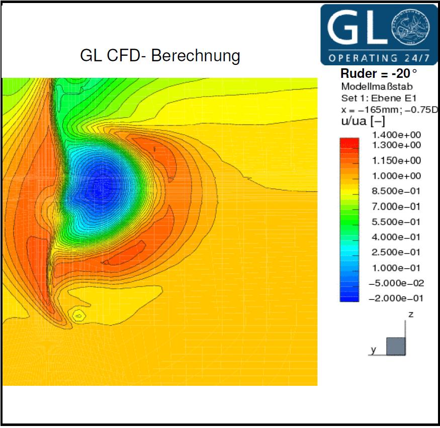
5 Figure 5: Measured velocities in ship s longitudinal direction in plane E1; rudder angle= +2 Figure 8: As Figure 5, but computed Figure 6: Measured velocities in ship s longitudinal direction in plane E1; rudder angle= Figure 9: As Figure 6, but computed Figure 7: Measured velocities in ship s longitudinal direction in plane E1; rudder angle= -2 Figure 1: As Figure 7, but computed
![Bending Biegespannung stress [N/mm²] 2 ] Figure 13: FEA model (right) and](/docs-images/74/70183843/images/6-0.jpg "location with highest computed stress (left) Figure 11: Cavitation clouds")

 and computed (black) rudder stock moments Measured Messung Computed")
 and measured (blue dots) max.")
6 Bending Biegespannung stress [N/mm²] 2 ] Figure 13: FEA model (right) and location with highest computed stress (left) Figure 11: Cavitation clouds in full-scale observations (top) and computed iso-surface with concentration of c=.1 water vapour (bottom) Figure 14: Time histories of full-scale measured (red) and computed (black) rudder stock moments Measured Messung Computed Berechnung Rudder Anstellwinkel angle [ ] [ ] Figure 12: Computed (red line) and measured (blue dots) max. bending stress of rudder stock Figure 15: 2D- investigated horizontal cuts


 Figure 19: Pressure")
 and")
7 Figure 18: Geometrical variations of rudder sole Figure 16: 2D- investigations with XFOIL: Run of the pressure coefficient across the original profile (top) and across one of the profile variations (bottom) Original Design New Design Figure 17: Streamlines of particles in the area of a gap; original profile (top) and a profile variation (bottom) Figure 19: Pressure distribution around rudder sole of original rudder design (top) and around new design with end plate (bottom)
![CY [-] CM [-] Original Design New Design Figure 2: Pressure and cavitation (gray: iso-surface of a VoF](/docs-images/74/70183843/images/8-0.jpg "cav-concentration of.")
 distribution at the new rudder design at 5 (top) and 1 (bottom) rudder angle 1,6")
![Rudder blade + horn CY,6 Rudder blade CM 1,4 1,2 1,8,6,4,2 -,2 5 1 15 2 25 3 35 Angle [ ],4,2 -,2 5 1 15 2 25 3 35](/docs-images/74/70183843/images/8-2.jpg "-,4 -,6 -,8 -,1 Angle [ ] Origin design New design Origin design New design Figure 21: Transverse force coefficient")
8 CY [-] CM [-] Original Design New Design Figure 2: Pressure and cavitation (gray: iso-surface of a VoF cav-concentration of.1) distribution for original rudder design at 5 (top) and 1 (bottom) rudder angle Figure 22: Pressure and cavitation (gray: iso-surface of a VoF cav-concentration of.1) distribution at the new rudder design at 5 (top) and 1 (bottom) rudder angle 1,6 Rudder blade + horn CY,6 Rudder blade CM 1,4 1,2 1,8,6,4,2 -, Angle [ ],4,2 -, ,4 -,6 -,8 -,1 Angle [ ] Origin design New design Origin design New design Figure 21: Transverse force coefficient of original and new rudder design Figure 23: Rudder stock moment coefficient of original and new design
Investigation of Scale Effects on Ships with a Wake Equalizing Duct or with Vortex Generator Fins
 Second International Symposium on Marine Propulsors smp 11, Hamburg, Germany, June 2011 Investigation of Scale Effects on Ships with a Wake Equalizing Duct or with Vortex Generator Fins Hans-Jürgen Heinke,
Numerical and Experimental Investigation of the Possibility of Forming the Wake Flow of Large Ships by Using the Vortex Generators
 Second International Symposium on Marine Propulsors smp 11, Hamburg, Germany, June 2011 Numerical and Experimental Investigation of the Possibility of Forming the Wake Flow of Large Ships by Using the
Prognosis of Rudder Cavitation Risk in Ship Operation
 Prognosis of Rudder Cavitation Risk in Ship Operation Lars Greitsch, TUHH, Hamburg/Germany, lars.greitsch@tu-harburg.de 1 Introduction In the course of increase of the requirements, the necessity of more
Development of TEU Type Mega Container Carrier
 Development of 8 700 TEU Type Mega Container Carrier SAKAGUCHI Katsunori : P. E. Jp, Manager, Ship & Offshore Basic Design Department, IHI Marine United Inc. TOYODA Masanobu : P. E, Jp, Ship & Offshore
Development of Technology to Estimate the Flow Field around Ship Hull Considering Wave Making and Propeller Rotating Effects
 Development of Technology to Estimate the Flow Field around Ship Hull Considering Wave Making and Propeller Rotating Effects 53 MAKOTO KAWABUCHI *1 MASAYA KUBOTA *1 SATORU ISHIKAWA *2 As can be seen from
Numerical analysis of influence of streamline rudder on screw propeller efficiency
 POLISH MARITIME RESEARCH 2(65) 2010 Vol 17; pp. 18-22 10.2478/v10012-010-0013-4 Numerical analysis of influence of streamline rudder on screw efficiency Tomasz Abramowski, Ph. D. akub Handke, M. Sc. Tadeusz
A Holistic Design Approach for Propulsion Packages
 Third International Symposium on Marine Propulsors smp 13, Launceston, Australia, May 2013 A Holistic Design Approach for Propulsion Packages Lars Greitsch 1, Markus Druckenbrod 2, Sven Bednarek 2, Hans-Jürgen
THE PERFORMANCE OF PLANING HULLS IN TRANSITION SPEEDS
 THE PERFORMANCE OF PLANING HULLS IN TRANSITION SPEEDS BY DOYOON KIM UNIVERSITY OF SOUTHAMPTON LIST OF CONTENTS AIM & OBJECTIVE HYDRODYNAMIC PHENOMENA OF PLANING HULLS TOWING TANK TEST RESULTS COMPUTATIONAL
Forest Winds in Complex Terrain
 Forest Winds in Complex Terrain Ilda Albuquerque 1 Contents Project Description Motivation Forest Complex Terrain Forested Complex Terrain 2 Project Description WAUDIT (Wind Resource Assessment Audit and
Study of Passing Ship Effects along a Bank by Delft3D-FLOW and XBeach1
 Study of Passing Ship Effects along a Bank by Delft3D-FLOW and XBeach1 Minggui Zhou 1, Dano Roelvink 2,4, Henk Verheij 3,4 and Han Ligteringen 2,3 1 School of Naval Architecture, Ocean and Civil Engineering,
Minyee Jiang, Malarie Vanyo, Jason Updegraph, Evan Lee Naval Surface Warfare Center at Carderock May 12, 2010 STAR Aerospace & Defense Conference 2010
 Minyee Jiang, Malarie Vanyo, Jason Updegraph, Evan Lee Naval Surface Warfare Center at Carderock May 12, 2010 STAR Aerospace & Defense Conference 2010 Introduction CFD Validation and Simulation for RIB
Abstract. 1 Introduction
 Developments in modelling ship rudder-propeller interaction A.F. Molland & S.R. Turnock Department of Ship Science, University of Southampton, Highfield, Southampton, S017 IBJ, Hampshire, UK Abstract A
New Hydrodynamic Aspects of Double Ended Ferries with Voith- Schneider Propeller Dirk Jürgens, Voith Schiffstechnik Rainer Grabert, SVA Potsdam
 New Hydrodynamic Aspects of Double Ended Ferries with Voith- Schneider Propeller Dirk Jürgens, Voith Schiffstechnik Rainer Grabert, SVA Potsdam 1. Introduction Voith-Schneider propellers (VSP) have proved
Aerodynamic study of a cyclist s moving legs using an innovative approach
 Aerodynamic study of a cyclist s moving legs using an innovative approach Francesco Pozzetti 30 September 2017 Abstract During a period of four weeks in September, I completed a research project in fluid
Engineering Practice on Ice Propeller Strength Assessment Based on IACS Polar Ice Rule URI3
 10th International Symposium on Practical Design of Ships and Other Floating Structures Houston, Texas, United States of America 2007 American Bureau of Shipping Engineering Practice on Ice Propeller Strength
Figure 1 Figure 1 shows the involved forces that must be taken into consideration for rudder design. Among the most widely known profiles, the most su
 THE RUDDER starting from the requirements supplied by the customer, the designer must obtain the rudder's characteristics that satisfy such requirements. Subsequently, from such characteristics he must
Propeller and Rudder in Off-Design Conditions
 Third International Symposium on Marine Propulsors smp 13, Launceston, Tasmania, Australia, May 2013 Propeller and Rudder in Off-Design Conditions Thomas Lücke 1 1 Hamburgische Schiffbau-Versuchsanstalt
Numerical Analysis of the Propeller with Economical Cap by CFD
 Numerical Analysis of the Propeller with Economical Cap by CFD 1.Introduction Yoshihisa Okada*, Kenta Katayama* and Akinori Okazaki* Propeller Design department, Nakashima Propeller Co.,Ltd. 688-1, Joto-Kitagata,
Operating Conditions Aligned Ship Design and Evaluation
 First International Symposium on Marine Propulsors smp 09, Trondheim, Norway, June 2009 Operating Conditions Aligned Ship Design and Evaluation Lars Greitsch, Georg Eljardt, Stefan Krueger Hamburg University
A Study on Roll Damping of Bilge Keels for New Non-Ballast Ship with Rounder Cross Section
 International Ship Stability Workshop 2013 1 A Study on Roll Damping of Bilge Keels for New Non-Ballast Ship with Rounder Cross Section Tatsuya Miyake and Yoshiho Ikeda Department of Marine System Engineering,
A COMPUTATIONAL STUDY ON THE DESIGN OF AIRFOILS FOR A FIXED WING MAV AND THE AERODYNAMIC CHARACTERISTIC OF THE VEHICLE
 28 TH INTERNATIONAL CONGRESS OF THE AERONAUTICAL SCIENCES A COMPUTATIONAL STUDY ON THE DESIGN OF AIRFOILS FOR A FIXED WING MAV AND THE AERODYNAMIC CHARACTERISTIC OF THE VEHICLE Jung-Hyun Kim*, Kyu-Hong
The Wake Wash Prediction on an Asymmetric Catamaran Hull Form
 The Wake Wash Prediction on an Asymmetric Catamaran Hull Form Omar Yaakob, Mohd. Pauzi Abd. Ghani, Mohd. Afifi Abd. Mukti, Ahmad Nasirudin, Kamarul Baharin Tawi, Tholudin Mat Lazim Faculty of Mechanical
Centre for Offshore Renewable Energy Engineering, School of Energy, Environment and Agrifood, Cranfield University, Cranfield, MK43 0AL, UK 2
 Fluid Structure Interaction Modelling of A Novel 10MW Vertical-Axis Wind Turbine Rotor Based on Computational Fluid Dynamics and Finite Element Analysis Lin Wang 1*, Athanasios Kolios 1, Pierre-Luc Delafin
Numerical Propeller Rudder Interaction Studies to Assist Fuel Efficient Shipping
 Numerical Propeller Rudder Interaction Studies to Assist Fuel Efficient Shipping Charles Badoe 1*, Alexander Phillips 1 and Stephen R Turnock 1 1 Faculty of Engineering and the Environment, University
INVESTIGATION OF HYDRODYNAMIC PERFORMANCE OF HIGH-SPEED CRAFT RUDDERS VIA TURBULENT FLOW COMPUTATIONS, PART I: NON-CAVITATING CHARACTERISTICS
 Journal of Marine Science and Technology, Vol. 13, No. 1, pp. 61-72 (2005) 61 Short Paper INVESTIGATION OF HYDRODYNAMIC PERFORMANCE OF HIGH-SPEED CRAFT RUDDERS VIA TURBULENT FLOW COMPUTATIONS, PART I:
PRESSURE DISTRIBUTION OF SMALL WIND TURBINE BLADE WITH WINGLETS ON ROTATING CONDITION USING WIND TUNNEL
 International Journal of Mechanical and Production Engineering Research and Development (IJMPERD ) ISSN 2249-6890 Vol.2, Issue 2 June 2012 1-10 TJPRC Pvt. Ltd., PRESSURE DISTRIBUTION OF SMALL WIND TURBINE
ITTC Recommended Procedures Testing and Extrapolation Methods Manoeuvrability Free-Sailing Model Test Procedure
 Testing and Extrapolation Methods Free-Sailing Model Test Procedure Page 1 of 10 22 CONTENTS 1. PURPOSE OF PROCEDURE 2. DESCRIPTION OF PROCEDURE 2.1 Preparation 2.1.1 Ship model characteristics 2.1.2 Model
Conventional Ship Testing
 Conventional Ship Testing Experimental Methods in Marine Hydrodynamics Lecture in week 34 Chapter 6 in the lecture notes 1 Conventional Ship Testing - Topics: Resistance tests Propeller open water tests
ITTC Recommended Procedures and Guidelines
 Page 1 of 6 Table of Contents 1. PURPOSE...2 2. PARAMETERS...2 2.1 General Considerations...2 3 DESCRIPTION OF PROCEDURE...2 3.1 Model Design and Construction...2 3.2 Measurements...3 3.5 Execution of
Rudder Propeller Hull Interaction: The Results of Some Recent Research, In-Service Problems and Their Solutions
 First International Symposium on Marine Propulsors smp 09, Trondheim, Norway, June 2009 Rudder Propeller Hull Interaction: The Results of Some Recent Research, In-Service Problems and Their Solutions John
Influence of rounding corners on unsteady flow and heat transfer around a square cylinder
 Influence of rounding corners on unsteady flow and heat transfer around a square cylinder S. K. Singh Deptt. of Mech. Engg., M. B. M. Engg. College / J. N. V. University, Jodhpur, Rajasthan, India Abstract
Transitional Steps Zone in Steeply Sloping Stepped Spillways
 Transitional Steps Zone in Steeply Sloping Stepped Spillways Jalal Attari 1 and Mohammad Sarfaraz 2 1- Assistant Professor, Power and Water University of Technology, Iran 2- Graduate Student, Department
Abstract. 1 Introduction
 Parametric analysis of hull structure of mono- and catamaran-type inland vessels T. Jastrzebski & Z. Sekulski Faculty ofmaritime Technology, Technical University of Szczecin, AL Piastow 41, 71-065 Szczecin,
The effect of back spin on a table tennis ball moving in a viscous fluid.
 How can planes fly? The phenomenon of lift can be produced in an ideal (non-viscous) fluid by the addition of a free vortex (circulation) around a cylinder in a rectilinear flow stream. This is known as
Cavitation Research on a Very Large Semi Spade Rudder
 First International Symposium on Marine Propulsors smp 9, Trondheim, Norway, June 9 Cavitation Research on a Very Large Semi Spade Rudder Thomas Lücke 1, Heinrich Streckwall 1 1 Hamburgische Schiffbau-Versuchsanstalt
A STUDY OF THE LOSSES AND INTERACTIONS BETWEEN ONE OR MORE BOW THRUSTERS AND A CATAMARAN HULL
 A STUDY OF THE LOSSES AND INTERACTIONS BETWEEN ONE OR MORE BOW THRUSTERS AND A CATAMARAN HULL L Boddy and T Clarke, Austal Ships, Australia SUMMARY CFD analysis has been conducted on a 100m catamaran hull
Sea-going vessel versus wind turbine
 Collision risk at high sea Sea-going vessel versus wind turbine Offshore wind power: Wind turbines off the German coast generally represent obstacles in the traffic routes of ships. What if a large sea-going
CFD development for wind energy aerodynamics
 CFD development for wind energy aerodynamics Hamid Rahimi, Bastian Dose, Bernhard Stoevesandt Fraunhofer IWES, Germany IEA Task 40 Kick-off Meeting 12.11.2017 Tokyo Agenda BEM vs. CFD for wind turbine
Vessel Modification and Hull Maintenance Considerations Options & Pay Back Period or Return On Investments
 Vessel Modification and Hull Maintenance Considerations Options & Pay Back Period or Return On Investments By Dag Friis Christian Knapp Bob McGrath Ocean Engineering Research Centre MUN Engineering 1 Overview:
Experience with Small Blade Area Propeller Performance
 Fifth International Symposium on Marine Propulsors smp 17, Espoo, Finland, June 2017 Experience with Small Blade Area Propeller Performance Thomas Lücke 1, Heinrich Streckwall 1 1 Hamburgische Schiffbau-Versuchsanstalt
SPECTRAL CHARACTERISTICS OF FLUCTUATING WIND LOADS ON A SEPARATE TWIN-BOX DECK WITH CENTRAL SLOT
 The Seventh Asia-Pacific Conference on Wind Engineering, November 8-, 009, Taipei, Taiwan SPECTRAL CHARACTERISTICS OF FLUCTUATING WIND LOADS ON A SEPARATE TWIN-BOX DEC WITH CENTRAL SLOT Le-Dong Zhu, Shui-Bing
Steady State Comparisons HAWC2 v12.5 vs HAWCStab2 v2.14: Integrated and distributed aerodynamic performance
 Downloaded from orbit.dtu.dk on: Jan 29, 219 Steady State Comparisons v12.5 vs v2.14: Integrated and distributed aerodynamic performance Verelst, David Robert; Hansen, Morten Hartvig; Pirrung, Georg Publication
Measurement and simulation of the flow field around a triangular lattice meteorological mast
 Measurement and simulation of the flow field around a triangular lattice meteorological mast Matthew Stickland 1, Thomas Scanlon 1, Sylvie Fabre 1, Andrew Oldroyd 2 and Detlef Kindler 3 1. Department of
CFD AND EXPERIMENTAL STUDY OF AERODYNAMIC DEGRADATION OF ICED AIRFOILS
 Colloquium FLUID DYNAMICS 2008 Institute of Thermomechanics AS CR, v.v.i., Prague, October 22-24, 2008 p.1 CFD AND EXPERIMENTAL STUDY OF AERODYNAMIC DEGRADATION OF ICED AIRFOILS Vladimír Horák 1, Dalibor
Research on Small Wind Power System Based on H-type Vertical Wind Turbine Rong-Qiang GUAN a, Jing YU b
 06 International Conference on Mechanics Design, Manufacturing and Automation (MDM 06) ISBN: 978--60595-354-0 Research on Small Wind Power System Based on H-type Vertical Wind Turbine Rong-Qiang GUAN a,
Understanding Details of Cavitation
 Second International Symposium on Marine Propulsors smp 11, Hamburg, Germany, June 2011 Understanding Details of Cavitation Anne Boorsma 1, Stewart Whitworth 1 1 Technical Investigation Department, Lloyd's
Numerical Simulation And Aerodynamic Performance Comparison Between Seagull Aerofoil and NACA 4412 Aerofoil under Low-Reynolds 1
 Advances in Natural Science Vol. 3, No. 2, 2010, pp. 244-20 www.cscanada.net ISSN 171-7862 [PRINT] ISSN 171-7870 [ONLINE] www.cscanada.org *The 3rd International Conference of Bionic Engineering* Numerical
L'evoluzione delle tecniche sperimentali nell'idrodinamica navale Particle Image Velocimetry, potenzialità, criticità ed applicazioni
 L'evoluzione delle tecniche sperimentali nell'idrodinamica navale Particle Image Velocimetry, potenzialità, criticità ed applicazioni Massimo Falchi, Mario Felli, Giovanni Aloisio, Silvano Grizzi, Fabio
Wind tunnel effects on wingtip vortices
 48th AIAA Aerospace Sciences Meeting Including the New Horizons Forum and Aerospace Exposition 4-7 January 2010, Orlando, Florida AIAA 2010-325 Wind tunnel effects on wingtip vortices Xin Huang 1, Hirofumi
STRIDE PROJECT Steel Risers in Deepwater Environments Achievements
 STRIDE PROJECT Steel Risers in Deepwater Environments Achievements 1999-21 Neil Willis Principal Engineer 2H Offshore Engineering 6 th Annual Deepwater Technologies and Developments Conference 21 The presentation
Investigation on 3-D Wing of commercial Aeroplane with Aerofoil NACA 2415 Using CFD Fluent
 Investigation on 3-D of commercial Aeroplane with Aerofoil NACA 2415 Using CFD Fluent Rohit Jain 1, Mr. Sandeep Jain 2, Mr. Lokesh Bajpai 3 1PG Student, 2 Associate Professor, 3 Professor & Head 1 2 3
Numerical and Experimental Investigations of Lift and Drag Performances of NACA 0015 Wind Turbine Airfoil
 International Journal of Materials, Mechanics and Manufacturing, Vol. 3, No., February 2 Numerical and Experimental Investigations of Lift and Drag Performances of NACA Wind Turbine Airfoil İzzet Şahin
The Usage of Propeller Tunnels For Higher Efficiency and Lower Vibration. M. Burak Şamşul
 The Usage of Propeller Tunnels For Higher Efficiency and Lower Vibration M. Burak Şamşul ITU AYOC 2014 - Milper Pervane Teknolojileri Company Profile MILPER is established in 2011 as a Research and Development
Incompressible Potential Flow. Panel Methods (3)
") Incompressible Potential Flow Panel Methods (3) Outline Some Potential Theory Derivation of the Integral Equation for the Potential Classic Panel Method Program PANEL Subsonic Airfoil Aerodynamics Issues
Incompressible Potential Flow Panel Methods (3) Outline Some Potential Theory Derivation of the Integral Equation for the Potential Classic Panel Method Program PANEL Subsonic Airfoil Aerodynamics Issues
Injector Dynamics Assumptions and their Impact on Predicting Cavitation and Performance
 Injector Dynamics Assumptions and their Impact on Predicting Cavitation and Performance Frank Husmeier, Cummins Fuel Systems Presented by Laz Foley, ANSYS Outline Overview Computational Domain and Boundary
OPTIMIZATION OF SINGLE STAGE AXIAL FLOW COMPRESSOR FOR DIFFERENT ROTATIONAL SPEED USING CFD
 http:// OPTIMIZATION OF SINGLE STAGE AXIAL FLOW COMPRESSOR FOR DIFFERENT ROTATIONAL SPEED USING CFD Anand Kumar S malipatil 1, Anantharaja M.H 2 1,2 Department of Thermal Power Engineering, VTU-RO Gulbarga,
Computational Analysis of the S Airfoil Aerodynamic Performance
 Computational Analysis of the 245-3S Airfoil Aerodynamic Performance Luis Velazquez-Araque and Jiří Nožička 2 Department of Mechanical Engineering National University of Táchira, San Cristóbal 5, Venezuela
Experimental Investigation of the Effect of Waves and Ventilation on Thruster Loadings
 First International Symposium on Marine Propulsors SMP 9, Trondheim, Norway, June 29 Experimental Investigation of the Effect of Waves and Ventilation on Thruster Loadings Kourosh Koushan; Silas J. B.
NUMERICAL INVESTIGATION OF THE FLOW BEHAVIOUR IN A MODERN TRAFFIC TUNNEL IN CASE OF FIRE INCIDENT
 - 277 - NUMERICAL INVESTIGATION OF THE FLOW BEHAVIOUR IN A MODERN TRAFFIC TUNNEL IN CASE OF FIRE INCIDENT Iseler J., Heiser W. EAS GmbH, Karlsruhe, Germany ABSTRACT A numerical study of the flow behaviour
Laminar Flow Sections for Proa Boards and Rudders
 Laminar Flow Sections for Proa Boards and Rudders Thomas E. Speer, Des Moines, Washington, USA ABSTRACT Hydrofoil section designs for proa sailboats which reverse direction in a shunt when changing tacks
SIMMAN 2014 Systems based methods page 1 Instructions for submitting of manoeuvring predictions
 SIMMAN 2014 Systems based methods page 1 CONTENTS 1 INTRODUCTION AND OBJECTIVE... 2 2 SHIPS AND MANOEUVRES... 4 2.1 Selectable ships... 4 2.2 Manoeuvres to be simulated... 5 3 SUBMISSION PROCEDURES...
CFD Analysis and Experimental Study on Impeller of Centrifugal Pump Alpeshkumar R Patel 1 Neeraj Dubey 2
 IJSRD - International Journal for Scientific Research & Development Vol. 3, Issue 2, 21 ISSN (online): 2321-613 Alpeshkumar R Patel 1 Neeraj Dubey 2 1 PG Student 2 Associate Professor 1,2 Department of
Study on Marine Propeller Running in Bubbly Flow
 Third International Symposium on Marine Propulsors smp 13, Launceston, Tasmania, Australia, May 2013 Study on Marine Propeller Running in Bubbly Flow Chiharu Kawakita Mitsubishi Heavy Industries, Ltd.,
High speed video and hull pressure synchronisation to improve propeller design
 High speed video and hull pressure synchronisation to improve propeller design G.P.J.J. Hagesteijn, Ing. Maritime Research Institute Netherlands (MARIN), The Netherlands SYNOPSIS Nowadays, one of the questions
Voith Water Tractor Improved Manoeuvrability and Seakeeping Behaviour
 Amsterdam, The Netherlands Organised by the ABR Company Ltd Day Paper No. 2 9 Voith Water Tractor Improved Manoeuvrability and Seakeeping Behaviour Dr Dirk Jürgens and Michael Palm, Voith Turbo Schneider
A COMPARATIVE STUDY OF MIX FLOW PUMP IMPELLER CFD ANALYSIS AND EXPERIMENTAL DATA OF SUBMERSIBLE PUMP
 IMPACT: International Journal of Research in Engineering & Technology (IMPACT: IJRET) ISSN 2321-8843 Vol. 1, Issue 3, Aug 2013, 57-64 Impact Journals A COMPARATIVE STUDY OF MIX FLOW PUMP IMPELLER CFD ANALYSIS
Application of Simulation Technology to Mitsubishi Air Lubrication System
 50 Application of Simulation Technology to Mitsubishi Air Lubrication System CHIHARU KAWAKITA *1 SHINSUKE SATO *2 TAKAHIRO OKIMOTO *2 For the development and design of the Mitsubishi Air Lubrication System
ASME International Mechanical Engineering Congress & Exhibition IMECE 2013 November 15-21, 2013, San Diego, California, USA
 ASME International Mechanical Engineering Congress & Exhibition IMECE 2013 November 15-21, 2013, San Diego, California, USA IMECE2013-62734 AERODYNAMIC CHARACTERISTICS OF HORIZONTAL AXIS WIND TURBINE WITH
Advanced Applications in Naval Architecture Beyond the Prescriptions in Class Society Rules
 Advanced Applications in Naval Architecture Beyond the Prescriptions in Class Society Rules CAE Naval 2013, 13/06/2013 Sergio Mello Norman Neumann Advanced Applications in Naval Architecture Introduction
CRITERIA OF BOW-DIVING PHENOMENA FOR PLANING CRAFT
 531 CRITERIA OF BOW-DIVING PHENOMENA FOR PLANING CRAFT Toru KATAYAMA, Graduate School of Engineering, Osaka Prefecture University (Japan) Kentarou TAMURA, Universal Shipbuilding Corporation (Japan) Yoshiho
CFD Analysis of Giromill Type Vertical Axis Wind Turbine
 242 CFD Analysis Giromill Type Vertical Axis Wind Turbine K. Sainath 1, T. Ravi 2, Suresh Akella 3, P. Madhu Sudhan 4 1 Associate Pressor, Department Mechanical Engineering, Sreyas Inst. Engg. & Tech.,
Journal of Engineering Science and Technology Review 9 (5) (2016) Research Article. CFD Simulations of Flow Around Octagonal Shaped Structures
 (2016) Research Article. CFD Simulations of Flow Around Octagonal Shaped Structures") Jestr Journal of Engineering Science and Technology Review 9 (5) (2016) 72-76 Research Article JOURNAL OF Engineering Science and Technology Review www.jestr.org CFD Simulations of Flow Around Octagonal
Jestr Journal of Engineering Science and Technology Review 9 (5) (2016) 72-76 Research Article JOURNAL OF Engineering Science and Technology Review www.jestr.org CFD Simulations of Flow Around Octagonal
2-D Computational Analysis of a Vertical Axis Wind Turbine Airfoil
 2-D Computational Analysis of a Vertical Axis Wind Turbine Airfoil Akshay Basavaraj1 Student, Department of Aerospace Engineering, Amrita School of Engineering, Coimbatore 641 112, India1 Abstract: This
Aerodynamic Analysis of Blended Winglet for Low Speed Aircraft
 , July 1-3, 2015, London, U.K. Aerodynamic Analysis of Blended Winglet for Low Speed Aircraft Pooja Pragati, Sudarsan Baskar Abstract This paper provides a practical design of a new concept of massive
Two-way Fluid Structure Interaction (FSI) Analysis on the Suction Valve Dynamics of a Hermetic Reciprocating Compressor
 Analysis on the Suction Valve Dynamics of a Hermetic Reciprocating Compressor") Volume 118 No. 18 2018, 4241-4252 ISSN: 1311-8080 (printed version); ISSN: 1314-3395 (on-line version) url: http://www.ijpam.eu ijpam.eu Two-way Fluid Structure Interaction (FSI) Analysis on the Suction
Volume 118 No. 18 2018, 4241-4252 ISSN: 1311-8080 (printed version); ISSN: 1314-3395 (on-line version) url: http://www.ijpam.eu ijpam.eu Two-way Fluid Structure Interaction (FSI) Analysis on the Suction
Quantification of the Effects of Turbulence in Wind on the Flutter Stability of Suspension Bridges
 Quantification of the Effects of Turbulence in Wind on the Flutter Stability of Suspension Bridges T. Abbas 1 and G. Morgenthal 2 1 PhD candidate, Graduate College 1462, Department of Civil Engineering,
A numerical Euler-Lagrange method for bubble tower CO2 dissolution modeling
 A numerical Euler-Lagrange method for bubble tower CO2 dissolution modeling Author: Daniel Legendre & Prof. Ron Zevenhoven Åbo Akademi University Thermal and Flow Engineering Laboratory Turku, Finland
Numerical Analysis of Wings for UAV based on High-Lift Airfoils
 Numerical Analysis of Wings for UAV based on High-Lift Airfoils Sachin Srivastava Department of Aeronautical Engineering Malla Reddy College of Engineering & Technology, Hyderabad, Telangana, India Swetha
Prediction of Steady Performance of Contra-Rotating Propellers with Rudder
 Fourth International Symposium on Marine Propulsors smp 15, Austin, Texas, USA, June 2015 Prediction of Steady Performance of Contra-Rotating Propellers with Rudder Yasuhiko Inukai 1, Takashi Kanemaru
Dynamic Criteria 3rd June 2005
 Dynamic Intact Stability Criteria Scope. General The aim of this report is to introduce dynamic criteria for the intact stability of ships which cover the phenomena of parametric roll and pure loss of
Improved Aerodynamic Characteristics of Aerofoil Shaped Fuselage than that of the Conventional Cylindrical Shaped Fuselage
 International Journal of Scientific & Engineering Research Volume 4, Issue 1, January-213 1 Improved Aerodynamic Characteristics of Aerofoil Shaped Fuselage than that of the Conventional Cylindrical Shaped
An Investigation into the Capsizing Accident of a Pusher Tug Boat
 An Investigation into the Capsizing Accident of a Pusher Tug Boat Harukuni Taguchi, National Maritime Research Institute (NMRI) taguchi@nmri.go.jp Tomihiro Haraguchi, National Maritime Research Institute
Computing Added Resistance in Waves Rankine Panel Method vs RANSE Method
 Computing Added Resistance in Waves Rankine Panel Method vs RANSE Method Heinrich Söding, TU Hamburg-Harburg, Hamburg/Germany, h.soeding@tu-harburg.de Vladimir Shigunov, Germanischer Lloyd SE, Hamburg/Germany,
Copyright by Turbomachinery Laboratory, Texas A&M University
 Proceedings of the 2 nd Middle East Turbomachinery Symposium 17 20 March, 2013, Doha, Qatar Effectiveness of Windage Features on High Speed Couplings Steven Pennington Global Engineering Manager John Crane
Computer Simulation Helps Improve Vertical Column Induced Gas Flotation (IGF) System
 System") JOURNAL ARTICLES BY FLUENT SOFTWARE USERS JA187 Computer Simulation Helps Improve Vertical Column Induced Gas Flotation (IGF) System Computer simulation has helped NATCO engineers make dramatic improvements
JOURNAL ARTICLES BY FLUENT SOFTWARE USERS JA187 Computer Simulation Helps Improve Vertical Column Induced Gas Flotation (IGF) System Computer simulation has helped NATCO engineers make dramatic improvements
Dynamic Stall For A Vertical Axis Wind Turbine In A Two-Dimensional Study
 Abstracts of Conference Papers: TSBE EngD Conference, TSBE Centre, University of Reading, Whiteknights, RG6 Dynamic Stall For A Vertical Axis Wind Turbine In A Two-Dimensional Study R. Nobile 1,*, Dr M.
A methodology for evaluating the controllability of a ship navigating in a restricted channel
 A methodology for evaluating the controllability of a ship navigating in a restricted channel K. ELOOT A, J. VERWILLIGEN B AND M. VANTORRE B a Flanders Hydraulics Research (FHR), Flemish Government, Antwerp,
ITTC Recommended Procedures and Guidelines
 7.5 Page 1 of 11 Table of Contents... 2 1. PURPOSE OF PROCEDURE... 2 2. DESCRIPTION OF PROCEDURE... 2 2.1 Preparation 2 2.1.1 Ship model characteristics 2 2.1.1.1 Scale 2 2.1.1.2 Ship model 2 2.1.1.3 Tank
ROAD MAP... D-1: Aerodynamics of 3-D Wings D-2: Boundary Layer and Viscous Effects D-3: XFLR (Aerodynamics Analysis Tool)
") Unit D-1: Aerodynamics of 3-D Wings Page 1 of 5 AE301 Aerodynamics I UNIT D: Applied Aerodynamics ROAD MAP... D-1: Aerodynamics of 3-D Wings D-: Boundary Layer and Viscous Effects D-3: XFLR (Aerodynamics
Unit D-1: Aerodynamics of 3-D Wings Page 1 of 5 AE301 Aerodynamics I UNIT D: Applied Aerodynamics ROAD MAP... D-1: Aerodynamics of 3-D Wings D-: Boundary Layer and Viscous Effects D-3: XFLR (Aerodynamics
AIRFOIL PROFILE OPTIMIZATION OF AN AIR SUCTION EQUIPMENT WITH AN AIR DUCT
 THERMAL SCIENCE, Year 2015, Vol. 19, No. 4, pp. 1217-1222 1217 AIRFOIL PROFILE OPTIMIZATION OF AN AIR SUCTION EQUIPMENT WITH AN AIR DUCT by Li QIU a,b, Rui WANG a,*, Xiao-Dong CHEN b, and De-Peng WANG
International Journal of Offshore and Coastal Engineering Vol.1 No. 1 pp August 2017 e-issn: Department of Ocean Engineering ITS
 International Journal of Offshore and Coastal Engineering Vol.1 No. 1 pp. 16 21 August 2017 e-issn: 2580-0914 2017 Department of Ocean Engineering ITS Submitted: December 12, 2016 Revised: March 13, 2017
Investigation of Suction Process of Scroll Compressors
 Purdue University Purdue e-pubs International Compressor Engineering Conference School of Mechanical Engineering 2006 Investigation of Suction Process of Scroll Compressors Michael M. Cui Trane Jack Sauls
FEA ANALYSIS OF PRESSURE VESSEL WITHDIFFERENT TYPE OF END CONNECTIONS
 FEA ANALYSIS OF PRESSURE VESSEL WITHDIFFERENT TYPE OF END CONNECTIONS Deval Nitin Bhinde 1 and Rajanarsimha S. 2 1 MTech CAD-CAM & Robotics, 2 Facculty, Department of Mechanical Engineering K.J. Somaiya
THEORETICAL EVALUATION OF FLOW THROUGH CENTRIFUGAL COMPRESSOR STAGE
 THEORETICAL EVALUATION OF FLOW THROUGH CENTRIFUGAL COMPRESSOR STAGE S.Ramamurthy 1, R.Rajendran 1, R. S. Dileep Kumar 2 1 Scientist, Propulsion Division, National Aerospace Laboratories, Bangalore-560017,ramamurthy_srm@yahoo.com
Impact of Hull Propeller Rudder Interaction on Ship Powering Assessment
 Impact of Hull Propeller Rudder Interaction on Ship Powering Assessment Charles Badoe, University of Southampton, United Kingdom,ceb1r14@soton.ac.uk Stephen Turnock, University of Southampton, United Kingdom,s.r.turnock@soton.ac.uk
OPTIMIZING THE LENGTH OF AIR SUPPLY DUCT IN CROSS CONNECTIONS OF GOTTHARD BASE TUNNEL. Rehan Yousaf 1, Oliver Scherer 1
 OPTIMIZING THE LENGTH OF AIR SUPPLY DUCT IN CROSS CONNECTIONS OF GOTTHARD BASE TUNNEL Rehan Yousaf 1, Oliver Scherer 1 1 Pöyry Infra Ltd, Zürich, Switzerland ABSTRACT Gotthard Base Tunnel with its 57 km
Geometry Modification For Minimizing The Aeroelastics Effect
 Geometry Modification For Minimizing The Aeroelastics Effect Fariduzzaman a, Subagyo a, Fadilah Hasim a and Matza Gusto Andika a a Aero-Gas dynamics and Vibration Laboratory (LAGG), BPPT, PUSPIPTEK, Serpong
EXPERIMENTAL ANALYSIS OF THE CONFLUENT BOUNDARY LAYER BETWEEN A FLAP AND A MAIN ELEMENT WITH SAW-TOOTHED TRAILING EDGE
 24 TH INTERNATIONAL CONGRESS OF THE AERONAUTICAL SCIENCES EXPERIMENTAL ANALYSIS OF THE CONFLUENT BOUNDARY LAYER BETWEEN A FLAP AND A MAIN ELEMENT WITH SAW-TOOTHED TRAILING EDGE Lemes, Rodrigo Cristian,
Evaluation of aerodynamic criteria in the design of a small wind turbine with the lifting line model
 Evaluation of aerodynamic criteria in the design of a small wind turbine with the lifting line model Nicolas BRUMIOUL Abstract This thesis deals with the optimization of the aerodynamic design of a small
AKHIL KARTHIKA AJITH
 Structural design and Stability of a 6,000 ton Capacity Floating Dock as per DNVGL Rules AKHIL KARTHIKA AJITH 7 th EMship cycle: September 2016 February 2018 Master Thesis Development Of Flap Rudder Systems