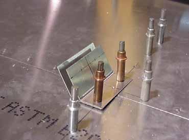
STOL CH V10-4SP Jury Strut Angle. Position the jury strut angle at rib station #2 (drawing 7-V-10) drill and Cleco.
|
|
|
- Clyde Sanders
- 6 years ago
- Views:
Transcription


1 7V10-4SP Jury Strut Angle Position the jury strut angle at rib station #2 (drawing 7-V-10) drill and Cleco. SECTION 4C - Page 1 of 11

2 SECTION 4C - Page 2 of 11


: Measure from the first hole in the rear rib to the spar center line.")
3 Turn the wing over. 7V7-1 Nose Skin TIP: If the nose skin is riveted on the bottom side of the wing, it may be difficult to turn the wing over recommend to support the edge of the skin with board and to have another person hold and support the board while two other sets of hands turn the wing over.. It may be easier to remove the nose skin before turning the wing over. After the wing is turned over, let the nose ribs overhang past the edge of the workbench and cleco nose skin to the bottom of the wing. The skin can be riveted at this stage. SPAR RIVET LINE (reference dimension): Measure from the first hole in the rear rib to the spar center line. This is a reference dimension to layout the spar rivet line when the nose skin is strapped down. Mark the reference dimension beside each rib. With a marker, layout the rib flange rivet line (flange center line) on the nose ribs. SECTION 4C - Page 3 of 11


4 Locate the end holes on the doubler. Use a square to extend the reference line to the rear skin. Photo looking at the top flange of the web doubler 7V2-6SP. Detail of inboard corner. It will work better using a 1 by 2 to hold down the skin until the straps are in position and secure to the wing. The leading edge skin is held in place with nylon ratchet straps at each rib station. SECTION 4C - Page 4 of 11


5 Letting the trailing edge rest on a 2 by 4 will work very well. Before tightening the straps make sure that the straps will not damage the wing. Using a 1 by 2 under the ratchet will protect the wing from damage. IMPORTANT: Level the wing. CHECK: The aft edge of the skin is even with the aft edge of the spar. Rivet line will be through the extrusion. SECTION 4C - Page 5 of 11


6 The skin should be tight to the nose ribs but be careful not to over tighten, Drill and cleco when the rib centerline is visible through the predrilled holes. Start drilling at the front and work your way back. Nose ribs drill and Clecoed. SECTION 4C - Page 6 of 11


7 A4 PITCH 40 Ref. top diagram on drawing 7-V-8 After drilling the nose ribs, layout the spar rivet line. Use this reference dimension measured on page 3 to layout the rivet line on the nose skin. Use a rivet spacing tool to layout the pitch between the intersection holes of the rib rivet line with the spar rivet line. Drill and Cleco. Looking inside the wing to confirm edge distance of the spar rivet line. SECTION 4C - Page 7 of 11


8 Wait to drill the spar tip 7V3-3 Wing tip. NOTE: The rivet line through the spar tip 7V3-3 is not in line with the main spar rivet line. DETAIL: end of spar at rear rib #6 SECTION 4C - Page 8 of 11


")
9 Wing root First hole is at the intersection of the spar with the rear rib #1 There are two rivet lines 20mm apart and at spar doubler 7V2-6SP Layout the rivet line through the web doubler 7V2-6SP. Layout the rivet line, then locate the end holes using the reference marked on the rear skin (see page 4) SECTION 4C - Page 9 of 11


10 Ref. middle top diagram on drawing 7-V-8 Photo of rivets O/B of nose rib #4 6 RIVETS A4 Photo of rivets I/B of nose rib #4 9 RIVETS A4 One rivet on the intersection of the nose rib rivet line and the spar rivet line. SECTION 4C - Page 10 of 11


11 Layout the rivet line for the rivet line through the bent L angle on the I/B side of the slat supports 7V4-5 Ref. text located at top left corner of drawing 7- V-8 Drill and Cleco the skin to the bend L angle. Ref nose ribs #3,#4, and #6. 4 RIVETS A4 SECTION 4C - Page 11 of 11
The slots for 7V4-5 have two predrilled holes. Locate them and connect them with a line. These will be at rib #1,3,4,6.
 7V7-1 Nose Skin The slots for 7V4-5 have two predrilled holes. Locate them and connect them with a line. These will be at rib #1,3,4,6. 7V7-1 Nose Skin The best way to cut the slot is by drilling a series
ZODIAC 601 XL. Position the main spar parallel to the edge of the workbench. Raise the wing skeleton on steel beams or spacers.
 Check: Sight down the rear channel 6W7-1 and the spar, check that they are straight. The aft edge of the channel is the reference to position the Rear skins. Position the main spar parallel to the edge
STOL CH 701. STOL CH 701 Bubble doors Rear view. Front view Right door. Revision 1.0 (10/03/2003) 2003 Zenith Aircraft Co
 2003 Zenith Aircraft Co") Bubble doors Rear view Front view Right door SECTION A - Page 1 of 12 7F19-12D Door Sill See Section 2 Door Final assembly The Door Sill is riveted to the sides of the Upper Tubes 7F12-2 with the wing
Bubble doors Rear view Front view Right door SECTION A - Page 1 of 12 7F19-12D Door Sill See Section 2 Door Final assembly The Door Sill is riveted to the sides of the Upper Tubes 7F12-2 with the wing
ZODIAC CH 601 XL. Tail Dragger (TD) or tail wheel configuration. TD configuration (shown with dual stick option and center console).
 or tail wheel configuration. TD configuration (shown with dual stick option and center console).") Tail Dragger (TD) or tail wheel configuration TD configuration (shown with dual stick option and center console). Ref 6B11-2 No cutout in the side skin 6B11-2 for the gear channel 6B5-5 When converting
Tail Dragger (TD) or tail wheel configuration TD configuration (shown with dual stick option and center console). Ref 6B11-2 No cutout in the side skin 6B11-2 for the gear channel 6B5-5 When converting
C75-RA-2 Rudder Skin
 C75-RA-2 Rudder Skin This manual has been prepared for assembly of the Rudder supplied with finished hole size, match drilled parts. This photo assembly manual is intended as a supplement to the drawings.
STOL CH rd Edition Drawings, dated April 16, 2012 Summary of changes from Edition 2 Revision 1 to Edition 3.
 STOL CH 750 3 rd Edition Drawings, dated April 16, 2012 Summary of changes from Edition 2 Revision 1 to Edition 3. Page Date Drawing Title 75-G-0 04/12 Three View Drawing 1. Edition 3 75-G-1 04/12 Drawings
Steps for W17, W14,W07, Wing Assembly Sonex #815
 CAUTION: This document is in no way a publication of Sonex Aircraft LLC. or any other corporation. All products mentioned are not necessarily recommended for use, but are included for informational purposes
CRACKS IN THE WING by Fred Keip
 CRACKS IN THE WING by Fred Keip As most of you know, my Sonerai IIL is old. On June 8 of 2011, she celebrated the 25 th anniversary of her first flight. She s also turned more than 1300 hours on her Hobbs
F-1279-R UPPER RIGHT SKIN F-1280-R RIGHT SIDE SKIN F-1281-R LOWER RIGHT SKIN F-1208-R FUSELAGE FRAME
 F-1282-R BOTTOM RIGHT SKIN F-1283C J-STIFFENER F-1278 TOP SKIN F-00009-L ADAHRS BRACKET F-00009-R ADAHRS BRACKET F-1279-R UPPER RIGHT SKIN F-1280-R RIGHT SIDE SKIN SECTION 10: TAILCONE F-1279-L UPPER LEFT
SECTION 23iS/U: SIDE SKINS
 SECTION 23iS/U: SIDE SKINS F-1203G-R BULKHEAD SIDE CHANNEL F-01248-R-1 ARM REST F-01205D SEAT BACK ADJUSTMENT GUIDE, 4 PLACES F-01205B-1 ROLL BAR ATTACH PLATE, F-01248B-1 FUSELAGE PIN LATCH, F-01204J BULKHEAD
SECTION 10iS: TAILCONE
 VAN'S AIRCRAFT, INC. F-1282-R BOTTOM RIGHT SKIN F-1283C J-STIFFENER F-1278 TOP SKIN F-00009-L ADAHRS BRACKET F-00009-R ADAHRS BRACKET F-1279-R UPPER RIGHT SKIN F-1280-R RIGHT SIDE SKIN SECTION 10iS: TAILCONE
CIRRUS AIRPLANE MAINTENANCE MANUAL
 RUDDER 1. GENERAL The rudder provides airplane directional (yaw) control and includes a rudder trim tab used for yaw trim adjustment. The rudder is of conventional design with skin, spar and ribs manufactured
Pitts Model 12 Wing Leading edge Installation
 Pitts Model 12 Wing Leading edge Installation This procedure is used to install molded plywood leading edges included in the Pitts Model 12 kit. Nine (9) molded leading edge section are require per aircraft;
Your kit contains the following items. Additional Items You May Need. Pre- cut parts Propeller rigging and rubber Sandpaper Covering sheet
 Your kit contains the following items Pre- cut parts Propeller rigging and rubber Sandpaper Covering sheet The SkyFox offers great glide performance in a rubber powered plane due to its built up wing.
Airframes. Chapter 5: Wings & Tailplane
 Airframes Chapter 5: Wings & Tailplane 1 2 Learning Objectives The purpose of this chapter is to discuss in more detail, 2 of the 4 major components, the Wing (or mainplane) and the Tailplane. By the end
CIRRUS AIRPLANE MAINTENANCE MANUAL MODELS SR22 AND SR22T CHAPTER 55-40: RUDDER GENERAL. Rudder 55-40: RUDDER. 1. General
 CIRRUS AIRPLANE MAINTENANCE MANUAL Rudder CHAPTER 55-40: RUDDER GENERAL 55-40: RUDDER 1. General The rudder provides airplane directional (yaw) control and includes a rudder trim tab used for yaw trim
Mount the actuator in the bracket provided and install a 24-foot EFTC cable to the actuator.
 . Mount the actuator in the bracket provided and install a 4-foot EFTC cable to the actuator. Route the cable through left stanchions,, and 4. Be sure that the cable does not contact any spring or push
Outbound Progress Report
 Outbound Progress Report 7-11-17 Tank Install The new 20 plus gallon fuel tank is underway. In a matter of weeks we should be getting the first article and placing a first run order. The tank fits like
Water Separators Installation & Operating Instructions THE SCIENCE OF SILENCE. Water Separators Installation & Operating Instructions 1
 Water Separators Installation & Operating Instructions THE SCIENCE OF SILENCE Water Separators Installation & Operating Instructions 1 Water Separators Correct installation is vital to safety and to avoid
BASIC AIRCRAFT STRUCTURES
 Slide 1 BASIC AIRCRAFT STRUCTURES The basic aircraft structure serves multiple purposes. Such as aircraft aerodynamics; which indicates how smooth the aircraft flies thru the air (The Skelton of the aircraft
TruckSkin System Installation Manual
 TruckSkin System Installation Manual TruckSkin 877-866-SKIN www.truckskin.com How to Install a TruckSkin Page 1...Questions? Call us at 877-866-7546 TruckSkin.com 1 2 Open your package and verify that
1/10 th Scale 1956 Ted Jones Classic Hydroplane
 1/10 th Scale 1956 Ted Jones Classic Hydroplane Preparation These plans show outside sheeting of 3/32 balsa laminated with 1/64 birch ply. This makes a light and strong skin for this boat. Optionally you
Dornier Do R 4 Super-Wal
 Dornier Do R 4 Super-Wal Model Aviation Laddie Mikulasko s Dornier Do R 4 Super-Wal Build the multiengine, record-setting seaplane. Article, plans, instructions, and photos by Laddie Mikulasko. Complete
Boat Boat Loader Fitting Instructions
 Aerodynamic & Heavy Duty Roof Rack Systems Australian Made - Australian Owned www.rhinorack.com Boat Boat Loader Fitting Instructions CONTROLLED Balance point 3 Front eye nuts position 3 Transom eye nut
The author's TD Coupe, used as a towplane, and the Airhopper. The gas model is equipped with an automatic towline release.
 THE AIRHOPPER BY STANLEY ORZECK PLANS BY PAUL PLECAN An eight-foot sailplane either towed by a gas model or launched by hand tow. The author's TD Coupe, used as a towplane, and the Airhopper. The gas model
Build This World Record Fuselage Model
 Build This World Record Fuselage Model Here You Have Complete Instructions and Plans to Build a Plane of Sure-fire Performance that Established a World Record at the 1932 National Airplane Model Competition
IMPORTANT: RECEIVING INSTRUCTIONS:
 Instruction Sheet Sidewinder Mechanical Bender IMPORTANT: RECEIVING INSTRUCTIONS: Visually inspect all components for shipping damage. If any shipping damage is found, notify carrier at once.shipping damage
QUALITY ALUMINUM BOAT LIFTS, INC. INSTRUCTIONS. Dominator Lake Lift
 INSTRUCTIONS Dominator Lake Lift PHONE:251-986-3882 * FAX:251-986-3136 QABLDOMINATORINST.2014 P a g e 1 Quality Aluminum Boat Lifts, INC. Installation Instructions: Dominator Lake Lift Thank you for your
Table of content Introduction 5 1. Part 1. Assembly Tools needed for Assembly Glossary Hulls Mounting the beams 7
 Table of content Introduction 5 1. Part 1. Assembly 6 1.1. Tools needed for Assembly 6 1.2. Glossary 6 1.3. Hulls 7 1.3.1. Mounting the beams 7 1.3.2. Fixing the mast rotation cleats 8 1.3.3. Placing the
Wing assemblyfinal Master 4/29/04 11:20 PM Page 1. Issued January 1, Sabre Aircraft. Assembly Manual. Sabre 16ss Wing
 Wing assemblyfinal Master 4/29/04 11:20 PM Page 1 Issued January 1, 2002 Sabre Aircraft Assembly Manual Sabre 16ss Wing Wing assemblyfinal Master 4/29/04 11:20 PM Page 2 1. 2. 1. Unzip the cover and remove
Bench Trimming A Stunt Ship
 Bench Trimming A Stunt Ship by Brett Buck "Bench Trimming" - this refers to setting up the initial trim of the airplane in the shop prior to flight. Since people have been flying stunt in its current form
V-Tail Flamingo. Included in Kit * Pre- cut balsa parts * Ballast weights * Diagram sheet * Sandpaper sheet
 V-Tail Flamingo Included in Kit * Pre- cut balsa parts * Ballast weights * Diagram sheet * Sandpaper sheet Additional Items You May Need * Wood Glue * Epoxy Glue * Sanding block * Hobby knife Overview:
ROADEO EVENTS LAYOUTS & DIAGRAMS. (January 8, 2018)
") ROADEO EVENTS LAYOUTS & DIAGRAMS (January 8, 2018) 1 The Roadeo Events Layout book was developed as a guide to assist in the set-up of Roadeo events for practice and/or competition. It is recommended that
ROADEO EVENTS LAYOUTS & DIAGRAMS (January 8, 2018) 1 The Roadeo Events Layout book was developed as a guide to assist in the set-up of Roadeo events for practice and/or competition. It is recommended that
Installation Guide, MPower Echelon Console
 Installation Guide, MPower Echelon Console AC Performance, AC Sport and AC Performance Plus Schwinn Echelon Console (External Routing) 1. Install batteries to console. Mount the console to the bike. 2.
Big Ride ASSEMBLY AND INSTALLATION INSTRUCTIONS * * C A U T I O N * *
 Big Ride ASSEMBLY AND INSTALLATION INSTRUCTIONS * * C A U T I O N * * S.R. SMITH BIG RIDE SLIDES ARE MANUFACTURED FOR INSTALLATION AND USE ON INGROUND SWIMMING POOLS ONLY. THE BIG RIDE IS NEVER TO BE INSTALLED
Shiel e d Kite t By B y Sam & Ca C rir King Ore r g e o g n o Kite t m e aker e rs s Retr t e r a e t t2013
 Shield Kite By Sam & Cari King Oregon Kitemaker s Retreat 2013 SAIL ASSEMBLY Your pre-cut sail pieces include half-inch seam allowances. This provides enough material to complete a 1/4 inch double rolled
NATIONAL TRANSPORTATION SAFETY BOARD Office of Research and Engineering Materials Laboratory Division Washington, D.C
 NATIONAL TRANSPORTATION SAFETY BOARD Office of Research and Engineering Materials Laboratory Division Washington, D.C. 20594 May 7, 1999 Report No. 99-74 SEQUENCING GROUP STUDY ON EXPLOSION OF CENTER WING
Falcon 3 145, 170, 195 and Tandem Owner / Service Manual
 Falcon 3 145, 170, 195 and Tandem Owner / Service Manual January 2007 - Second Edition Removing The Sail From The Airframe And Short Packing The Glider Many maintenance and repair procedures will require
Plans and Instructions to build a folding reflector oven
 Plans and Instructions to build a folding reflector oven Kayak2go.com also has folding kayak plans available for purchase. The low cost and ease of construction make the folding kayaks a great youth group
WHEEL-RESTING SIDE LIFT
 R EQ U I R ED EQ U I P M ENT WHEEL-RESTING SIDE LIFT 1 Res-Q-Jack Strut 1 Res-Q-Jack Lifting Jack 1 Chain & Hook Assembly 3 Ratchet Strap with Wire Hooks 4 Clusters any necessary cribbing, chocks, stakes,
Akcent-2 - Building Instructions
 Akcent-2 Home Pictures Building Instructions Ordering Akcent-2 - Building Instructions Note! The pictures show older kits with "diser" wings. The new kits come with nicer D-box wings. Servo locations are
Holden Grate-Lock Chock Inspection and Repair Standards: Procedure and Examples (April 2016)
") Holden Grate-Lock Chock Inspection and Repair Standards: Procedure and Examples (April 2016) This document is the property of IL, LLC, and should only be used in connection with the Holden Grate-Lock Chock
Holden Grate-Lock Chock Inspection and Repair Standards: Procedure and Examples (April 2016) This document is the property of IL, LLC, and should only be used in connection with the Holden Grate-Lock Chock
REVISION LIST CHAPTER 8: OUTBOARD WING SECTION CLOSING
 REVISION LIST CHAPTER 8: The following list of revisions will allow you to update the Legacy construction manual chapter listed above. Under the Action column, R&R directs you to remove and replace the
THE AMERICAN BARN DOOR KITE
 THE AMERICAN BARN DOOR KITE Oregon Kitemaker s Retreat January 2007 Rod Beamguard 4104 NW 112 th Way Vancouver, WA 98685-3578 (360) 574-8050 home (360) 750-9833 office kytfevr@wa-net.com PLANFORM BARN
Instant Garage 20' x 12' 3" x 8' 3"
 Instant Garage 20' x 12' 3" x 8' 3" Assembly Instructions Description Model # Instant Garage 20' x 12' 3" x 8' 3" - Grey CIG 1220 3503502 Recommended Tools OR THIS IS A TEMPORARY STRUCTURE AND NOT RECOMMENDED
AIRCRAFT STRUCTURAL DESIGN & ANALYSIS K. RAMAJEYATHILAGAM
 AIRCRAFT STRUCTURAL DESIGN & ANALYSIS K. RAMAJEYATHILAGAM To invent an airplane is nothing To build one is something But to fly is everything Lilienthal DAY 1 WHAT IS AN AIRCRAFT? An aircraft is a vehicle,
Annex E(M) - Final inspection checklist - monowheel
 - Final inspection checklist - monowheel") Annex E(M) - Final inspection checklist - monowheel A/C Reg... Owner...Kit S/N...Date... (U.K. Only) L.A.A No...Inspector...Insp. No... Note: This check list only covers specific items for inspection of
Annex E(M) - Final inspection checklist - monowheel A/C Reg... Owner...Kit S/N...Date... (U.K. Only) L.A.A No...Inspector...Insp. No... Note: This check list only covers specific items for inspection of
Main Wing Wood Parts
 Main Wing Wood Parts WR 1-11 TE LE MS1 MS2 ST MS3 Before you start the build, gather all the required main wing components. QTY o MS1 (Main Spar 1) 2 o MS2 (Main Spar 2) 2 o MS3 (Main Spar 3) 2 o ST (Servo
ORNAMENTAL CANTILEVER GATE INSTRUCTIONS
 U.S.A. Patent Number 5,36,83 ORNAMENTAL CANTILEVER GATE INSTRUCTIONS *NOTICE: Ornamental Cantilever Gates are supplied with rolls of 2 mesh safety screening in sufficient quantities to cover the entire
Step 1: Block sand the transom to remove the seam joint. The end result should be a flat transom without a ledge where the seam joint is.
 WhiplashGV Instruction Manual Email: Brian@Blazermarine.com Phone: 513-598-1769 Step 1: Block sand the transom to remove the seam joint. The end result should be a flat transom without a ledge where the
02 - Wings/ Winglets. Wings /Winglets. April XLG Page 2-1
 Wings /Winglets April 2006 02-XLG Page 2-1 This Page Intentionally Left Blank Page 2-2 02-XLG April 2006 Contents 2.0 - Chapter Preface...2-4 2.0.1 - Parts...2-4 2.0.2 - Tools List...2-5 2.0.3 - Supplies
ULTIMATE 12 RUDDER INSTALLATION INSTRUCTIONS
 ULTIMATE 12 RUDDER INSTALLATION INSTRUCTIONS TOOLS NEEDED: DRILL ¼ DRILL BIT ¾ HOLE SAW 3/16 DRILL BIT PHILLIPS HEAD SCREWDRIVER 7/16 WRENCH HEAT SOURCE: PROPANE TORCH, LIGHTER OR HOT AIR GUN WIRE CUTTER
Theory of Flight Aircraft Design and Construction. References: FTGU pages 9-14, 27
 Theory of Flight 6.01 Aircraft Design and Construction References: FTGU pages 9-14, 27 Main Teaching Points Parts of an Airplane Aircraft Construction Landing Gear Standard Terminology Definition The airplane
SERVICE INSTRUCTION SI Revision 2
 SERVICE INSTRUCTION SI-57-01 Revision 2 TITLE: VG/Swept Wing Tip Installation (Mod 1215) SUBJECT / REASON / DESCRIPTION: This Service Instruction describes the installation of the Full Span Vortex Generators
Wooden Dummy Construction
 Wooden Dummy Construction Mook Yan Jong - (pronounced moohk yàhn jàng) literally translates "wood man post", but is usually just called a "wooden dummy" in English, or "jong" for short. The dummy consists
Designed, like the CX4, to be easy to build for the first time builder. Very economical too. Meets the Light Sport requirements. Tandem two place.
 Designed, like the CX4, to be easy to build for the first time builder. Very economical too. Meets the Light Sport requirements. Tandem two place. 1 Dave focuses on the BEGINNING builder; one who has never
1939 STOUT TROPHY WINNER
 1939 STOUT TROPHY WINNER This model's 36-minute flight won the Stout Trophy and qualified the builder as captain of the American Moffett team. Bob Toft. Has won a second in gas, first in rubber at Nationals.
ESOCCI RIGGING MANUAL
 ESOCCI RIGGING MANUAL 1 Spray Covers Hull Rear Iako Forward Iako Ama ESOCCI RIGGING MANUAL 2 When training & racing in outrigger canoes, the canoe is your protector on the water and therefore it is imperative
32M. Sternpost, rudder & tailwheel
 32M. Sternpost, rudder & tailwheel Overview The sternpost, which was temporarily fitted earlier in the build process, will now be fitted permanently. The rudder is attached to the fin via three hinges
Team Building System Activity Instructions
 Thank you for purchasing this product from Gopher. If you are not satisfied with any Gopher purchase for any reason at any time, contact us and we will replace the product, credit your account, or refund
INSTALLATION INSTRUCTIONS FOR EXHAUST CUFF MODIFICATION
 INSTALLATION INSTRUCTIONS FOR EXHAUST CUFF MODIFICATION Document # PCA1001-22 Revision LTR: A Date: 07/06/09 1 Notes: 1. The cuff must be installed onto the aircraft prior to painting. Once installed the
LOAD HUGGER CARGO CONTROL
 Hugger BASICS Lift-All Hugger cargo control and load securement products are of the highest quality. They offer the van and flatbed operator a wide variety of options to meet Department of Transportation
MEASURING GUIDE CUSTOM SAFETY COVER. Please Submit this form as: Cover Style - Mesh. Contact Information. Cover Style - Solid
 CUSTOM SFETY COVER MESURING GUIDE Please Submit this form as: Quote Only Order Order No. Questions? Phone 1-855-467-4224 (toll free Monday-Friday 9am-5pm EST) FX 1-781-848-0507 or email us at customerservice@thepoolcenters.com
Pre-Paint>Fuselage>Empennage>Fit vertical tail fin. Objectives of this task: Materials and equipment required: Fit the spar extender
 Pre-Paint>Fuselage>Empennage>Fit vertical tail fin Objectives of this task: To fit the vertical tail fin to the fuselage, including fitting the static probe, static tube, optional strobe light wiring and
MEASURING GUIDE CUSTOM SAFETY COVER. Please Submit this form as: Cover Style - Mesh
 CUSTOM SFETY COVER MESURING GUIDE Please Submit this form as: Quote Only Order Order No. Questions? Phone 1-844-878-2964 (toll free Monday-Friday 9am-5pm EST) FX 1-781-848-0507 or email us at care@wholesalepoolcovers.com
PAY N PAK, 1/12 th Scale, Limited Sport Hydro P Sport Hydro
 1980 82 PAY N PAK, 1/12 th Scale, Limited Sport Hydro P Sport Hydro Introduction: The 1980 turbine Pay N Pak is a good subject for a model race boat. It has a low profile, mild pickle-fork setback, long
INSTRUCTIONS FOR CHAIN LINK INSTALLATION
 INSTRUCTIONS FOR CHAIN LINK INSTALLATION This guide explains how to correctly install our chain link fencing and post system. The guide provides details of which post type you will need for your fence
We hope you ll enjoy the Drifter as much as we have! Scott DeTray Model Aero Specifications:
 We are excited to bring you the Drifter RC airboat. You re probably thinking it doesn t fly so what is Model Aero thinking??? We have always liked RC vehicles of all types and have had a fondness for airboats
FDR CHRYSLER 16' CATAMARAN (MUSKETEER) The initial rigging of a sailboat is not difficult, but if the boat is strange
 The initial rigging of a sailboat is not difficult, but if the boat is strange") Page of 6 Revised 2/0/76 RIGGING INSTRUCTIONS FDR CHRYSLER 6' CATAMARAN (MUSKETEER) The initial rigging of a sailboat is not difficult, but if the boat is strange to the new owner, or the new owner is
Page of 6 Revised 2/0/76 RIGGING INSTRUCTIONS FDR CHRYSLER 6' CATAMARAN (MUSKETEER) The initial rigging of a sailboat is not difficult, but if the boat is strange to the new owner, or the new owner is
Gurney Flap for WRX and STI w/low Profile Trunk Spoiler
 Gurney Flap for 2015+ WRX and STI w/low Profile Trunk Spoiler 2017-12-05 Thank you for purchasing this PERRIN product for your car! Installation of this product should only be performed by persons experienced
Revisions to the Regulations for Agility Trials
 Revisions to the Regulations for Agility Trials Effective January 2, 2018 Equipment changes may be done prior to January 2, 2018, but must be completed by January 2, 2018 This insert is issued as a supplement
AVA Building Instructions
 Suggested Assembly Sequence: AVA Building Instructions 1. Insert fittings in rudder and trial fit rudder on boom 2. Attach stab to v-mount and position ahead of rudder ¼, sanding the v-mount as needed.
Riviera Draft Shaft Hole Boring
 Riviera Draft Shaft Hole Boring a. Height from bottom of hull thru the hull to the center of the drive shaft. This will be calculated. b. Height of drop of strut. The strut for the Riviera is 7.5 c. Distance
Rigging the Pitts by Doug Sowder, IAC #14590
 Rigging the Pitts by Doug Sowder, IAC #14590 Pitts not flying so straight anymore? Don t believe that a Pitts can fly hands-off? Maybe you need to set aside a Saturday and do some rigging. The maintenance
Manufacturing, Inc. Manual. Series I UT3030, UT5036, UT5042 & UT5052 (S/N KA1096A-) Rolling Spike Update Ultra-Till (Disc & Coulter)
 Rolling Spike Update Ultra-Till (Disc & Coulter)") Manual Series I UT3030, UT5036, UT5042 & UT5052 (S/N KA1096A-) Rolling Spike Update Ultra-Till (Disc & Coulter) Manufacturing, Inc.! Read the operator s manual entirely. When you see this symbol, the subsequent
Manual Series I UT3030, UT5036, UT5042 & UT5052 (S/N KA1096A-) Rolling Spike Update Ultra-Till (Disc & Coulter) Manufacturing, Inc.! Read the operator s manual entirely. When you see this symbol, the subsequent
Highlander Specifications
 Highlander Specifications July 22, 2012 Highlander Specifications The intent of this section is to clarify and add to what is shown in the official plans. In case of conflict between these specifications
RUDDER KIT INSTRUCTIONS
 C I N S T R U C T I O N S RUDDER KIT INSTRUCTIONS PAMLICOS-0,0,T, T, 60T, Excel Rotomolded Pamlico 0, 0, T, T, 60T, Excel The addition of a rudder to a kayak results in additional control and efficiency,
Thank you for purchasing a Porta-Dock product! *Please read and follow these instructions step by step*
 PG 1 OF 9 PORTA-DOCK, INC. 74A ABL/APW 1056 & 44A FLB APW 1056 PORTA-LIFT Thank you for purchasing a Porta-Dock product! *Please read and follow these instructions step by step* STEP 1. Separate and group
Start: Stand with feet slightly wider than hip-width and knees bent in a slight squat position.
 Squat with Side Tap Start: Stand with feet slightly wider than hip-width and knees bent in a slight squat position. Movement: Keeping the standing leg in a squat position, straighten the other leg out
CLEANROOM GEL GRID CEILING SYSTEM PRODUCT DATA Division
 5023 HAZEL JONES ROAD, BOSSIER CITY, LA 71111 888.315.1561 800.877.8746 FAX SALES@GORDONCLEANROOM.COM GORDONCLEANROOM.COM AN EMPLOYEE OWNED COMPANY CLEANROOM GEL GRID CEILING SYSTEM PRODUCT DATA Division
USG Ceiling Solutions. LOGIX Integrated Ceiling Systems INSTALLATION GUIDE
 USG Ceiling Solutions LOGIX Integrated Ceiling Systems INSTALLATION GUIDE LOGIX Integrated Ceiling Systems INSTALLATION GUIDE Logix Brand Integrated Ceiling Systems integrated ceiling systems from USG
Darling Downs Soaring Club Inc
 Darling Downs Soaring Club Inc Rigging and De-Rigging Instructions LS7 XOW Overview Page 2 Rigging page 3 De-Rigging page 19 Overview It is the pilot s responsibility to make sure that the trailer is fully
2008 Swan 42 Tuning Guide.
 2008 Swan 42 Tuning Guide. *The information in this guide applies to North 3DL Swan 42 Class sails only. Before going sailing: 1-Step mast with mast butt 4.2 cm aft of the bulkhead. Set mast at deck level
Counterbore and Countersink Tutorial
 Counterbore and Countersink Tutorial This tutorial is designed to show how to create a Counterbore hole in two different ways. 1. Creating 2 Extrudes 2. Using the Hole Tool Types of Holes Counterbore Holes
Making Spars for the Schooner Jeanette
 Making Spars for the Schooner Jeanette..... by Byron Rosenbaum Figure 1. Byron Rosenbaum s 1:16-scale radio-controlled model of the schooner Jeanette. All photographs by the builder. The spars required
Instant Garage 16' x 12' 3" x 8' 6"
 Instant Garage 16' x 12' 3" x 8' 6" Assembly Instructions Door Height 1.8M A B DESRIPTION MODEL # A B IG 1216 Instant Garage 4.9 x 3.7 x 2.6 M - Grey 3503500 16' x 12' 3" x 8' 6" REOMMENDED TOOLS OR Please
CONSTRUCTION NOTES BY: MARK HUNT ISSUED:
 INSIGHT V4 CONSTRUCTION NOTES BY: MARK HUNT ISSUED: 3/22/06 Pg.1 INDEX Title Page 1 Index 2 Introduction 3 Material list 4 Foam Cutting Notes 5 Wing 5 Stab 8 Vertical Fin 8 Fuselage Foam Parts 9 Fuselage
Trampoline & Enclosure Assembly Instructions
 Trampoline & Enclosure Assembly Instructions Safe user weight 330 lbs (150 kg) Version 718702 The information in this document is subject to change without notice. Copyright Springfree Trampoline Inc.
18. Tailplane torque-tube
 18. Tailplane torque-tube Step 1 Fu se lage rear bulkhead Remove the three part templates of the rear bulkhead: an A4 size sheet from Annex A (page 5) and two A3 size sheets from Annex F of the manual,
Far East Boat Optimist Rigging Instructions
 Far East Boat Optimist Rigging Instructions These instructions are written specifically for Far East Boats Championship and Racing Optimist. Parts of the Optimist PAGE 1 Sprit Wind Indicator Sail Mast
PERFECTING THE BUNT: Slap, Squeeze & Bunting for a Hit Cindy Bristow
 PERFECTING THE BUNT: Slap, Squeeze & Bunting for a Hit Cindy Bristow cindybristow@verizon.net FUNDAMENTALS OF BUNTING: Get in the FRONT of the Batter s Box Front of the box where bunter should stand Shows
SPIRAL PIPE - OVAL SINGLE WALL
 SPIRAL PIPE - OVAL SINGLE WALL Duct Direct Pipe and Fittings are manufactured in accordance with 2005 SMACNA Duct Construction Standards (1995 SMACNA Standards on request) OVAL SUBMITTAL Oval Single Wall
Coaches Handbook. Coaches Handout Page 1
 Coaches Handout 2009 Page 1 General Session 1: How to Warm-up! Players are put through basic warm-ups and exercises that they should perform each week when they come to Tball. Stretching should be the
RUDDER KIT INSTRUCTIONS
 A I N S T R U C T I O N S RUDDER KIT INSTRUCTIONS TARPON 0/40/60/60i The Tarpon series is designed as a high performance sit-on-top kayak tailored for the sport paddler. Our rudder system is designed to
RIFLE DRILL. 1. General. Before commencing instruction in rifle drill, it is important that the cadets receive instruction in the parts of the rifle.
 RIFLE DRILL 1. General. Before commencing instruction in rifle drill, it is important that the cadets receive instruction in the parts of the rifle. 2. Rifle Movements. Unless stated otherwise, cadets
2 X 4 PORTABLE ALUMINUM SOCCER GOALS
 Instruction and Safe Use Manual 2 X 4 PORTABL ALUMINUM SOCCR OALS SOOTOUT TM NO-TIP TM OR STANDARD OALS WARNIN! It is imperative that all Portable Soccer oals be used only in accordance with safety guidelines
Assembly Instructions. for. Puffin Saranac. ScanSport, Inc. P.O. Box 700 (234 May Street) Enfield, New Hampshire Phone: (603)
 Enfield, New Hampshire Phone: (603)") Assembly Instructions for Puffin Saranac ScanSport, Inc. P.O. Box 700 (234 May Street) Enfield, New Hampshire 03748 Phone: (603) 632 9500 Fax: (603) 632 5611 info@pakboats.com www.pakboats.com Assembling
Assembly Instructions for Puffin Saranac ScanSport, Inc. P.O. Box 700 (234 May Street) Enfield, New Hampshire 03748 Phone: (603) 632 9500 Fax: (603) 632 5611 info@pakboats.com www.pakboats.com Assembling
Peinert Dolphin. Assembly
 Peinert Dolphin Assembly The Dolphin is easily rigged; there are only four removable parts - the seat, the foot stretcher, the rigger arm, and the fin. Removal and installation of the seat. If the seat
2990 Lorne Scots Royal Canadian Army Cadet Corps Rifle Drill
 2990 Lorne Scots Royal Canadian Army Cadet Corps Rifle Drill Page 1 of 27 TABLE OF CONTENTS PARA ITEM PAGE Section 1 BASIC RIFLE DRILL 1.1 INTRODUCTION 3 1.2 ATTENTION 5 1.3 STAND AT EASE FROM ATTENTION
Stand-N-Fish FULL DETAIL INSTALLATION INSTRUCTIONS
 1 Stand-N-Fish FULL DETAIL INSTALLATION INSTRUCTIONS Thank you for purchasing the incredible new Stand-N-Fish Kayak Fishing System. Once installed on your kayak the Stand-N-Fish will take your kayak fishing