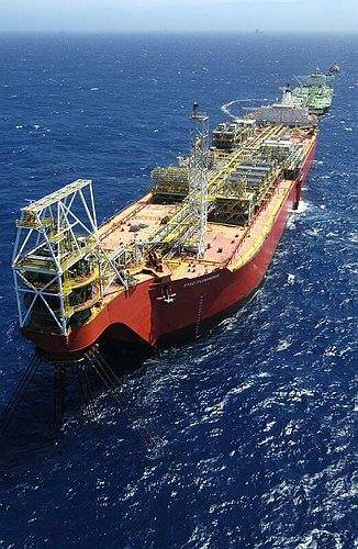
Spread Moored or Turret Moored FPSO s for Deepwater Field Developments
|
|
|
- Lora Hall
- 6 years ago
- Views:
Transcription
1 Spread Moored or Turret Moored FPSO s for Deepwater Field Developments G. Boyd Howell, FMC Technologies Floating Systems, USA Arun S. Duggal, FMC Technologies Floating Systems, USA Caspar Heyl, FMC Technologies Floating Systems, USA Oise Ihonde, MODEC International LLC, USA Offshore West Africa 2006 ABSTRACT From a mooring designer s perspective, a key component of the design of a deepwater spread moored FPSO is the integrated design of the mooring system with the vessel hull and topsides, riser and flowline systems, and the field layout. However, recent experience has shown that the mooring system for several deepwater fields have been designed without taking into account all the relevant interfaces, leading to expensive mid-project changes, increased component costs, and impact on schedule and installation. The objective of the paper is to provide a clear description of the various interfaces and issues that need to be considered when designing and laying out a mooring system to ensure an optimized mooring design for the FPSO. The paper addresses technical issues related to the design of the mooring system, the pull-in system and chain fairleads, and the installation of the mooring system and the FPSO. The paper is based on the authors experience in designing and installing the mooring systems for two Deepwater FPSOs off West Africa, and two FPSOs off Brazil. The paper will illustrate the design aspects for the mooring system including anchor leg layout and design, design of the pullin system, issues with installation, identifying the various interfaces between vessel, riser systems, and installation. 1
2 2
3 INTRODUCTION Deepwater oil fields are becoming more and more common and the use of a Floating (Production) Storage and Offloading systems (FPSOs) provide a mature technology for the production, storage and export of hydrocarbon products from these areas. FPSOs have been installed in a variety of configurations over the past thirty years. In general there are two options for mooring systems, either spread moored or turret moored. A spread moored FPSO involves a vessel moored by anchor legs from the bow and stern of the vessel in a four-group arrangement. The risers that transport the products to and from the vessel are suspended from riser porches on the side of the vessel. This type of mooring system maintains the vessel in a fixed orientation of the F(P)SO in global coordinates. A turret moored FPSO is designed as a Single Point Mooring (SPM) that allows the FPSO to weathervane about the mooring system, in response to the environment. This weathervaning ability allows the vessel to adapt its orientation with respect to the prevailing environmental direction to reduce the relative vessel-environment angles and the resulting load on the mooring. This also allows for a more optimum offloading orientation than that with a spread moored system. The riser systems are also supported within the turret structure. This paper compares the two FPSO systems by providing a description of the unique characteristics of the two mooring systems. This paper will not address the actual cost estimate or comparison between the two types of systems. A realistic comparison can only be performed for an actual field development where the basis design parameters are better known. There are many factors which influence the selection of a mooring system. These factors include details of the vessel, the environment, the subsea field architecture, the topsides equipment layout and the oil offloading requirements. The paper is divided into three sections: General comparison between turret and spead moored system Design and characteristics of atypical mooring system for Brazil Design and charactersistics of a typical spread mooring system for West Aftrica In conclusion the authors wish to show that in making the decision on which type of mooring system is best suited for a particular application all relevant factors should be considered. Often the decision can be swayed by incorrect application of one or more factors. In general it is possible to design either type of system for most applications, bearing in mind the preferences of the owners/operators. COMPARISON BETWEEN TURRET AND SPREAD MOORED SYSTEMS Turret Moored Systems Two types of turret systems are commonly used for F(P)SOs the internal turret system where the turret is mounted within the F(P)SO hull, and an external turret system where the turret is mounted on an extended structure cantilevered off the vessel bow. An FPSO turret system is a compact multi-functional structure that includes many stand-alone sub-systems found on other moored floating systems. The turret integrates the F(P)SO mooring system, the installation equipment for the anchor legs and the risers, the fluid-transfer system 3
4 including riser support, manifold, pig launching and receiving, metering, chemical injection, and subsea control systems into one compact, self-contained module. Figure 3 provides an illustration of the internal turret mooring system developed for the Barracuda early production system (P-34) in the Campos basin, offshore Brazil. This turret system was designed for 34 risers in water depth of 835 meters and installed in a converted 50,000 DWT tanker. The figure provides a good illustration of the various sub-systems and their typical arrangement within the internal turret mooring system. Since then FTI has completed an additional 10 turret moored F(P)SO projects. The mooring system of the internal turret includes the anchor legs, the turret shaft and the bearing system. The turret provides the load-transfer mechanism between the mooring and the vessel and also provides the mechanism for the weathervaning capability of the turret mooring system. The fluid-transfer system includes the support for the risers, the manifold, the injection, and the swivel stack systems that allow transfer of the fluids from the earth-fixed turret and risers to the weathervaning ship-fixed production system. In addition, the turret may include the installation system comprised of winches and sheaves. The 360-degree weathervaning feature of a turret moored F(P)SO significantly reduces the impact of greenwater on the vessel deck and production equipment and wave-frequency vessel motions, affecting both crew comfort and production plant uptime. As the F(P)SO maintains a heading into the predominant environment, greenwater is generally limited to the area forward of the turret and away from process and other key main deck systems. Also, vessel motions, particularly rolling motions, are typically reduced thus allowing more operating uptime during inclement weather conditions. This weathervaning ability is very important for the offloading operation as the headings of the F(P)SO and the export tanker are both into the predominant sea or winds, thus creating safer approaches and alignments during offloading operations. As the risers are contained within the turret structure, offloading operations are simplified as the F(P)SO hull is uncluttered with risers or exposed mooring lines. 4
 6 Anchor Legs + 34 Risers Figure 3: The P-34 Internal Turret Mooring System.")
5 Swivel Stack (Product/Lift/Controls) Manifolds & Pig Launching/ Receiving ESD Valves, Injection Skids Anchor Leg & Riser Installation Equipment Bearing Turret Shaft/Riser Guide Tubes Chain Table (Hawse Pipes/ Chain Supports) 6 Anchor Legs + 34 Risers Figure 3: The P-34 Internal Turret Mooring System. For a turret system, anchor legs may be arranged symmetrically or grouped in multiple sets of three or more legs such that openings between sets allow for varied and more direct riser approaches to their connections on the base of the turret. This direct approach may allow for more economical seabed flowline arrangements by eliminating loop routings around anchor leg arrays. In addition, turret mooring systems typically have fewer anchor legs of smaller component size than a mooring system for an equivalent spread moored F(P)SO. Until recently, internal turrets were assumed to be limited to 40 or so risers before the cost and turret congestion became unmanageable. Now, new and cost-effective turret designs can accommodate up to 100 or more risers in water depths ranging up to 2000 meters or more. Various designs for lower-cost external turret systems permit up to 40 or more risers for deepwater activities. Spread Mooring Systems Spread mooring or Multi-Point Mooring (MPM) systems have long been the traditional means of mooring all kinds of ships and barges in open and protected waters. For this type of mooring, multiple anchor lines extend from the bow and stern of the hull and anchor the unit to the seafloor in a fixed or slightly variable heading. Spread mooring systems can be designed for shallow or deepwater stationkeeping, in mild to moderate environments. The performance of the spread moored system is dependent on the prevailing weather and it is considered suitable for regions with a fairly restricted range of weather direction. They are not so effective, however, in harsh or 5
6 multi-directional environments where changing wind, waves and currents may impose severe loads on the anchoring system and create excessive motions on the unit. It is also important to consider the feasibility of offloading as a function of the day-to-day environment taking into account the approach and offloading operations with the export tanker. Figure 2 provides an illustration of a typical, large-field, spread moored F(P)SO system. The figure also indicates the various sub-systems identified within the turret mooring system and their typical location on the spread moored F(P)SO. Note how the various sub-systems are distributed about the deck of the F(P)SO. Also note the increasing complexity of the on-deck arrangement of the various F(P)SO systems that require additional interfaces between the various providers of design and equipment. All of these sub-systems must be accounted for in the CAPEX of a spread moored system when compared to that for a turret mooring system. For deepwater spread moored F(P)SO units, the number of anchor legs required may range between 12 and 20 lines, compared to 6 to 12 anchor legs for a turret moored system. Riser attachments for spread moored F(P)SO units are commonly located on porches installed along the length of the F(P)SO hull. The ability of a spread moored F(P)SO to accommodate a large number of risers (100 or more) provides the operator with additional flexibility with regards for installation, expansion and a more direct connection to individual wells by minimizing subsea manifolding. For many large spread moored F(P)SOs, the mooring system installation requires separate winches for the forward and aft anchor legs with a system of sheaves to allow access to each fairlead. This adds to the congestion on the deck and becomes a major interface requirement for the topsides arrangement for the ship and production systems of the vessel. The riser system typically requires its own winch and sheave arrangement. Anchor leg and riser arrangements for the spread moored F(P)SO often impact both the subsea arrangement of the flowlines and the selection of the offloading system. In order to limit the possibility of an anchor leg breaking and falling onto a subsea flowline, the flowlines are generally routed around the seabed anchor arrays so the risers approach the F(P)SO perpendicular to the riser porches. For safer operations, dual offloading systems on the vessel bow and stern to accommodate export tankers during changing environmental directions may be used, or even satellite export systems may be installed that move the offloading activities away from the F(P)SO system. Specialized dynamically positioned export tankers also may be also used for offloading from a spread moored F(P)SO. 6
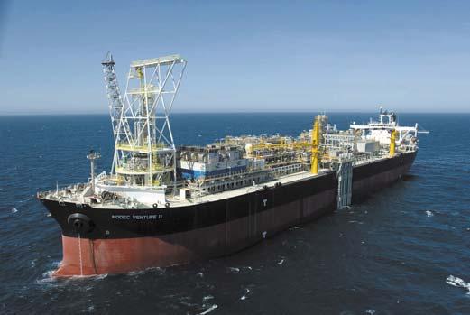
7 Mooring/Riser Pull-In Equipment Manifolds Pig Launching/Receiving Subsea Control Risers Anchor Legs Figure 2: Typical Large-Field New-build F(P)SO System. For the West African market FTI & MODEC combined have designed and installed 3 spread mooring systems and 2 External Turrets. Likewise, in the Brazilian arena FTI and MODEC have combined for 2 Internal Turret Moored systems, 2 External Turret Moored Systems and 1 Spread Moored system. The decision on which type of system to use for each of these projects was partly driven by company preference and partly by technical requirements. For projects with 100 risers or more, the likely solution will be a spread mooring, whereas for up to 30 risers the turret moored solution will most likely dominate. When making a decision of the type of system it is important to consider both CAPEX and OPEX of the complete system and not just the FPSO itself. The FPSO CAPEX, The offloading system CAEX, Offlaoding system availability and operational constraints must be addressed also. Possible Offloading Scenarios An important difference between a turret moored and spread moored F(P)SO system is the reliability and ease of use of the offloading operation. The choice of F(P)SO mooring systems can impact the reliability and equipment used for offloading liquid product from the unit. The offloading technique may be one or more of the following methods and is a function of whether the export tanker is a vessel of opportunity or from a dedicated tanker fleet. 7
8 Tandem Offloading: The export tanker approaches forward or aft of the F(P)SO, depending on sea and environmental conditions. It is then tethered by a hawser line downstream from the F(P)SO unit. Floating hoses from the F(P)SO are connected to the export tanker s manifold, and the product is transferred between the two units. Typically one to two assist tugs are used to keep tension on the hawser to maintain the tanker relative alignment with the F(P)SO and to prevent the tanker migration towards the F(P)SO during benign or changing sea conditions. This is the most common and preferred offloading arrangement for all F(P)SOs. It is a well-established offloading method in use at marine terminals and F(P)SOs for several decades and utilizes standard OCIMF equipment. In some regions of the world, dynamically positioned shuttle tankers are used that do not require assist tugs to maintain position during offloading. However, they are typically dedicated to a region or group of fields, and this dedicated feature reduces the favorable economics associated with the use of tankers of opportunity for offloading F(P)SO units. The overall field CAPEX and OPEX also increases substantially because of the investment, operating and maintenance costs associated with the dedicated tanker fleet. Satellite Offloading: A deepwater CALM buoy or other terminal structure is positioned some distance away from the F(P)SO unit (approximately one nautical mile). Flowlines are connected between the two facilities to allow the transfer of product to the export tanker moored to the terminal. While this distances the offloading operations from the F(P)SO, and provides excellent uptime over the life of the field, it also adds significant cost to the overall project for the installed buoy and flowlines, and the additional power and pumping requirements on board the F(P)SO. Side-by-Side Offloading: The export tanker is moored abreast of the F(P)SO and hoses or Chiksan loading arms are connected between both vessels to transfer the product. For spread moored F(P)SO units, this offloading method can be complicated as the export tanker must carefully navigate between the bow and stern anchor patterns to avoid collision with the hull or legs or risers (if nearby). This method of offloading is not very common for deepwater field developments because of the inherent risks. For spread moored F(P)SO systems, side-by-side and tandem offloading creates a high degree of exposure to collision as the F(P)SO remains fixed in position as the export tanker maneuvers about it. For a turret moor F(P)SO system, side-by-side and tandem operations are simplified as the unit s beams are uncluttered with risers or exposed mooring lines, however, the offloading system of choice is the tandem offloading for both tankers of opportunity or DP shuttle tankers. Also, the headings of the F(P)SO and the export tanker are both into the predominant sea or winds, thus creating safer approaches. For safer operations, expensive satellite export systems may be rationalized for spread moored F(P)SO units yet remain a debatable option for turret moored F(P)SO offloading. Pros and Cons of the Two Mooring Systems The description of the two mooring systems has highlighted many of the differences between a turret moored and spread moored system in terms of design and performance. Table 1 provides a comparative summary between the two systems that illustrates the differences discussed above. As discussed earlier, turret moored systems orient themselves to the prevailing environment direction that allows its use in harsh, multi-directional environments with minimized loads and vessel motions. A not so obvious advantage of a weathervaning turret mooring system is that as it adjusts itself to the prevailing environment it is not as sensitive to poor design environmental criteria which is common in areas where new development takes place. A spread moored system is moored in a fixed orientation and thus is more sensitive to global environment intensity and direction. The turret system provides a compact load and fluid-transfer system with a minimum 8
9 number of anchor legs required. The weathervaning ability helps provide more constant offloading conditions for export tankers, helicopter operations, and discharges from flares. However, the passive weathervaning ability of the turret mooring system requires the location of the turret at the vessel bow that is the location of the maximum vessel motions and thus requires a riser system that is robust enough to withstand the motions at the turret. A turret mooring system is not readily adapted to the addition/modification of riser systems (needs to be designed in to the system), and its design and fabrication requires specialized engineering and manufacturing techniques and knowledge. 9
10 Table 1: Comparative Summary of Turret Moored and Spread Moored F(P)SO Systems. Turret-Moored Spread-Moored Vessel Orientation 360 degree weathervaning Fixed orientation, can impact flare Environment Field Layout Riser Number & Arrangement Riser Systems Stationkeeping Performance Vessel Motions Vessel Arrangement Offloading Performance Mild to extreme, Fairly adaptable, partial to Requires commitment, Location of turret (bow) requires Number of anchor legs, Weathervaning capability Turret provides "compact" FPSO typically aligned with Mild to moderate, Prefers flowline arrangement to Can be designed for flexibility, Adapts to various riser systems, Larger number of anchor legs, Dependent on relative vessel/ Components spread on deck, Dependent on vessel/ directional to spread distributed flowline arrangements moderate expansion capability robust riser design offsets minimized reduces motions load and fluid transfer system mean environment uni- to fairly directional approach beam-on additional tie-ins combinations of various types offsets variable environment directionality requires extensive interfaces environment orientation An important aspect to consider with spread moored vessels is the offloading performance of the system over the life of the field. As the vessel orientation is fixed, a tandem moored export tanker has a limited range of relative heading with respect to the F(P)SO when tandem offloading from the vessel, especially in inclement weather, not directly aligned with the F(P)SO orientation. In order to maintain the shuttle within this allowable zone additional tug assistance may be required as compared to a similar turret moored system, or a second offloading station may be required at the other end of the F(P)SO to improve the offloading uptime. The environment mis-alignment with the F(P)SO orientation can also lead to difficulties in approaching and leaving the F(P)SO before and after the offloading of product. In extreme cases where the use of a spread moored system and multi-directional environmental conditions does not provide the desired uptime for tandem offloading, a satellite offloading station may be installed approximately one nautical mile from the F(P)SO. In deepwater, flowlines are suspended between the F(P)SO and the remote offloading station (typically a large CALM buoy). Considering the basis of design for the development, the various sub-systems and components can be addressed and a comparison between the two mooring types, including engineering, management, and fabrication/assembly costs can be made. The capital costs (CAPEX) of the two systems Moorings: This includes all systems of the mooring to vessel load-transfer system including anchor leg components, fairleads and chainstoppers, the turret structure, mooring installation equipment, etc. 10
11 Fluid-Transfer: This includes all equipment required for fluid-transfer from the risers to the topsides production stream. This includes the riser porches, manifolding, pig launching and receiving, swivel stack, riser specific installation equipment, etc. Hull Modifications: This group includes mooring system specific modifications for the hull, e.g., the turret moonpool, underwater fairlead supports, bending shoes, bilge keels, etc. Topsides Systems: This includes equipment specific to topside system cost due to mooring system selection, e.g. metering, chemical injection skids, electrical and hydraulic systems that may be located in a turret system, modifications to topsides to accommodate the selection of either system, etc. Offloading System: This includes the specific offloading system components required for each mooring system type. This includes offloading system related equipment on board the vessel and remote offloading systems and associated flowlines if required. Installation: This includes all installation costs to installing and hook-up the FPSO to its moorings and remote offloading system if required. Services and Administration: This includes all engineering, management, procurement and mark-up costs associated with the spread moored or turret moored specific items described above. The operational costs (OPEX) of the two systems Demurrage: Tanker demurrage time and charges. Maintenance and Inspection: This includes all maintenance and inspection requirements for the mooring system specific components including the requirements for a remote offloading system if utilized. Offloading Tugs and Pilots: This includes the costs for offloading assistance from support vessels, and pilots required for navigation around the FPSO. The offloading costs are developed to provide a relative offloading OPEX cost as this has been used to ensure comparable offloading performance from both F(P)SOs. Offloading Hoses and Hawsers: Replacement costs associated with replacing hoses and hawsers with each system, based on standard industry practice. Production loss due to excessive vessel motions is computed as a relative cost difference between the spread moored and turret moored systems rather than the actual values for each system obtained from the analysis. This minimizes the high sensitivity of the overall cost estimate to production loss, compared to the CAPEX and OPEX costs associated with the two systems. The Present Value (PV) of the two systems serves as a method of comparing the total cost of the mooring systems on the same time reference, accounting for inflation and the present value of future expenses. The PV for each case study is based on a 10.5% discount rate computed from the first oil milestone. 11

12 Figure 9: Illustration of a large capacity internal turret for offshore Brazil.. Services & Administrative Installation Mooring Offloading System Spread Mooring Hull Systems Topside Systems Fluid Transfer Services & Administrative Installation Offloading System Mooring Turret Mooring Hull Systems Topside Systems Fluid Transfer Comparison between a spread moored and a turret moored FPSO in Brazil. 12
13 Flowlines A long standing misconception is the capacity of turret mooring systems to support large number of risers. FMC Technologies has developed large internal turret systems that are capable of supporting over a 100 risers. Because of the reduced number of anchor legs and anchor leg groups required for a turret mooring system, a turret mooring system will have more seabed area available between the mooring lines on the seabed [1]. Recently FMC Technologies proposed an external turret solution accommodating 33 risers for use on the Frade field in 1,000 meters of water in the Campos basin. Figure 1 illustrates the arrangement if risers on an external turret. Both turret moorings and spread moorings are expandable, but require planning for additional risers during the initial construction. In the case of a turret mooring, slots for additional future risers need to be arranged in the turret. In the case of a spread mooring, provisions for additional risers will have to be made in the riser porch structures, at deck level and at or near keel level. General Layout of mooring system and flowlines During the initial phase of the project, thought must be given to the way that flowlines are routed on the seabed. Typically, mooring arrangements are determined in a FEED study phase using results from preliminary mooring analysis to determine mooring system characteristics such as the number of mooring lines, the mooring line plan angles and anchor radius. More detailed mooring analysis, in particular the verification of the minimum fatigue life at a later stage may indicate that a much larger chain size is needed to satisfy fatigue life design criteria. The results of a detailed study that investigated the effect of mooring system footprint on the fatigue resistance of the mooring system indicate that these changes could have been prevented if a fatigue analysis had been performed as part of the FEED study [2]. The layout of the mooring lines and flowlines on the seabed can also have a significant effect on the feasibility of the selected riser system. During the detailed riser analysis for a recently installed spread mooring project in Brazil it was found that for the risers to work in a catenary configuration, the vessel offsets needed to be kept below 8% [3]. This offset limitation is below the maximum offset criteria of 10% that is typically given to the mooring designer. Because the mooring design typically precedes the detailed riser analysis by 12 months or more, this can create a situation whereby it becomes desirable to make changes to the mooring design late in the project while the mooring line components are being manufactured. Vessel Motions Extreme roll motions are greater for a spread moored FPSO since maximum beam sea condition is a 7 meter significant sea. Since the wind wave and current systems in the Campos basin are not strongly correlated, large angles between vessel and waves can also occur for turret moored FPSOs albeit for reduced wave heights. However, in recent years, Petrobras has increased the design significant wave height to be used for beam sea conditions for turret moored FPSO s from 3.5 to 5.7 meters. The result of this is that maximum roll angles for spread moored and turret moored FPSOs are getting closer. In the Campos Basin, both spread moored and turret moored FPSO are fitted with extra wide bilge keels (1-1.5meters) to keep extreme roll motions to below 10 degrees. Figure 2 shows a model of an FPSO in Campos Basin beam sea conditions. Because of the significant beam sea conditions (up to a significant wave height of 7 meters with a relatively short spectral peak period) vertical accelerations along the side of a spread moor can be higher than those at the turret location for an internal or even external turret. 13
14 A comparison between two recent model test campaigns carried out by FMC Technologies showed that maximum vertical accelerations near the riser hang-off locations on a spread moored FPSO were actually higher (3.2 m/s2) than those measured on for an FPSO with an external turret mooring (2.1 m/s2). In addition, the large beam sea condition can lead to wave slamming issues on the riser balcony along the side of the vessel in the full draft condition. Figure 3 shows wave slamming around the riser porch area observed during FPSO model tests. Offloading availability Currently there are far more turret moored FPSOs in the Campos Basin than Spread Moored, but of the last nine FPSO projects in the Campos Basin, five use a spread mooring. From this recent experience with spread moorings it is becoming clear that in the Campos Basin, offloading availability for a spread moored FPSO is lower than for a turret moored FPSO even when one takes into account that the spread moored FPSOs have offloading stations on both the bow and the stern. The difference in operability of the export system between spread mooring and turret mooring is even greater in West Africa where most large FPSOs are installed with a separate single point mooring for the purpose of exporting crude. Mooring system Design. One of the main differences between the Campos Basin in Brazil and West Africa is the environment. In West Africa, the largest waves are limited to a narrow 45-degree sector centered around South-Southwest, while in Brazil, severe wave conditions approach the platforms from a 90-degree sector between Southwest and Southeast. The result for a spread mooring system is that in Brazil large wave conditions are encountered at large angles to the bow of the vessel, which result in larger mooring loads. Using a turret mooring system will reduce the relative wave angles for the larger sea states and result in smaller mooring components. From recent project experience it was found that in the Campos Basin, for a given water depth, the mooring system for a turret mooring used only half as many mooring lines (9) as a spread mooring (18), and that at the same time the breaking strength of the mooring lines used on the turret mooring (750 metric tons) was half of those needed for the spread mooring (1500 metric tons). 14


15 Figure 1 Example of riser arrangement on an external turret. 15

16 Figure 2. FPSO model test of Campos Basin beam sea conditions Figure 3. FPSO model test showing wave slamming on riser porch area. Design and Characteristics of a Typical Spread-Mooring System for West Africa Spreadmoored FPSOs are popular in West Africa due to the relatively benign and highly directional wave environment, and the typical fields that have been developed. Large FPSOs (typically 150,000 to 250,000 barrels of oil/day) also incorporate an offloading buoy and associated flow lines to provide the desired uptime and reliability for offloading. For smaller FPSO developments (around100,000 barrels of oil/day) a turret mooring system is considered an optimum solution with tandem offloading from the stern of the FPSO. Tandem loading from spreadmoored FPSOs are only considered to be an emergency option or used off very small FPSOs (say up to 50,000 barrels of oil/day) where an average of one to two offloadings are performed a month. Optimization of the design of a spreadmooring for large West Africa FPSOs requires the integration of the mooring design with major components of the FPSO system. Key interfaces include the vessel hull and topsides, riser and flowline systems, and the field layout. The following subsections detail the impact of the various design parameters on the mooring system: Environmental Conditions Field Layout Performance Requirements Integration with Hull and Topsides Impact of Risers and Oil Offloading Lines Installation & Hook-up 16
17 Environmental Conditions The environment offshore West Africa can be characterized by persistent long-period swells from the SSW with uncorrelated low-intensity wind and current environments. The environment is also characterized by squalls that are of short duration (typically one hour) and very high wind speeds (5 sec gust greater than 30m/s). Squalls typically originate over land and propagate over the ocean, but locally can be incident from almost any direction. These high wind speeds coupled with the very large FPSO systems results in large vessel offsets and thus anchor leg tensions, and typically govern the design of the mooring system from an extreme load and offset perspective. As the vessel is typically oriented with its bow, or stern towards the SSW the loading from the swell on the FPSO is minimized but due to its persistence results in defining the fatigue life of the mooring system. For the FPSOs with offloading buoys the buoys are typically located North of the FPSO to optimize the approach and departure of the tankers of opportunity. However, the nature of the environment can also lead to large crossed conditions (wind, waves and current from very different directions) and thus result in the tanker orientation being quite varied. Mooring System Design and Interface with Riser System Mooring systems for spread-moored FPSOs offshore West Africa typically are designed as grouped mooring systems with fairleads at the corners of the vessel. Typically the number of anchor legs range from twelve to sixteen with three or four anchor legs in each group, approximately 5 degrees apart. The anchor legs typically have a taut or semi-taut configuration and constructed with chain and spiral strand wire or polyester rope. The mooring system is anchored using suction embedded piles or vertically loaded anchors. For water depths greater than 1,000 meters the fairlead to anchor horizontal distance is typically 1-2 times the water depth. Typical maximum vessel offsets for an intact mooring system are 5% - 7% of water depth. The layout of the mooring system during the FEED stage of the project is extremely important as it plays a large role in determining the performance of the mooring and its cost and effectiveness as changes to the mooring layout during detailed design is difficult to accomplish due maturation of the subsea layout. It is quite typical in preliminary engineering to consider a symmetric mooring arrangement with anchor points determined from a simple analysis or rule of thumb, but experience has shown that insufficient attention to the mooring design at this stage can have a detrimental impact on the system at a later stage. One reason for this is that the mooring design must take into account the riser and oil offloading lines (OOL) loads. Also experience has shown that the anchor legs towards the swell environment (towards the SW) are also susceptible to fatigue damage and that increasing the distance to the anchor (closer to 2 times the water depth) can result in much better mooring performance and overall lower mooring costs. Due to the weight and length of these OOLs, each OOL exerts a horizontal force on the FPSO that is equivalent to that of an anchor leg. In addition the large FPSOs have a large number of risers attached to the vessel that also exert large horizontal forces on the vessel. Summing up the external forces from the OOLs and risers results in large surge and sway forces, and a yaw moment that have to be counteracted by the mooring system in addition to the environmental loads to maintain the vessel at the desired heading and position. The asymmetry of the external forces caused by risers and the OOLs attached to one end of the vessel result in the design of an asymmetric mooring system. The mooring asymmetry may either 17
18 be accomplished by varying the number of anchor legs in a group and/or varying the pre-tension and anchor leg length. One characteristic of such a mooring is that the stiffness is also asymmetric and thus for a given load, vessel offset will vary as a function of direction. The mooring system is typically softest when offset away from the offloading buoy as the force from the OOLs is fairly constant with offset. Another unusual characteristic of such an FPSO mooring system is that the static equilibrium position of the FPSO may vary by 10 meters with change in draft from ballast to fully loaded. These response characteristics are extremely important when transferring design information to the riser analysts and designers. The riser designs for spreadmoored FPSOs in deepwater have very restrictive vessel offset requirements (typically 5% of water depth), especially if steel catenary risers are used. Due to the yaw motions of the spread-moored vessel (especially in squall environments) the design offsets of the vessel may vary by 50% depending on whether it is attached near midships or near the bow/stern. This coupled with the asymmetric stiffness characteristics of the mooring system requires a clear specification of vessel offset as a function of the incident environment. This requires the mooring and riser designers to work closely in the design phase to ensure that consistent environmental conditions and vessel response data is used to design the riser system. Integration with Hull and Topsides The anchor leg fairleads can be either keel mounted or deck mounted depending on project construction and operational requirements. The selection of fairlead type can have a large impact on the hull construction. Keel mounted fairleads are more complex and need to be installed in dry dock and the arrangement/number/size must be determined fairly early in the project design cycle to ensure proper integration with the hull. Deck mounted fairleads are typically simpler and are mounted on the main deck with stiffeners to support them and can be installed at any time during the hull/topsides fabrication. The keel mounted fairleads provide clear access on both sides of the vessel while deck mounted fairleads restrict the access to the vessel sides. Keel mounted fairleads may also require guide tubes for the chain from the keel to the main deck. The fairlead arrangement also impacts the design of the pull-in system that could be a winch, chain jack or combination. For spread moorings (in contrast to turret systems) the pull-in system can take a large amount of real estate on the deck and the design of the pull-in system must consider the topsides arrangement, the location of structural supports and marine equipment on the deck, and other obstructions. The retrieval lines are directed to the various fairleads using a series of sheaves that also take a lot of real estate on the deck and need to be supported. The mooring pull-in system may also be used to pull-in the riser and oil offloading lines and thus requires a fairly good definition of all the risers and their locations. Mooring System Installation and FPSO Hook-up Installation of deepwater mooring systems presents numerous technical challenges both in terms of installing the individual anchor legs and in hooking up the vessel. This is further complicated in West Africa due to the presence of persistent swell and the unpredictable nature and intensity of West African squalls. Unlike other regions of the world where there exist periods where the seas are relatively calm due to the small wave heights and short wave periods, the long period swell results in the installation vessels undergoing relatively large heave and pitch motions that results in increased dynamics during lifting and lowering operations. Most permanent mooring systems in West Africa are anchored using suction piles that may weight MT. During the lowering operation a vessel heave of 1 meter amplitude can result in the suction pile heaving +/- 4 meters due to the 18
19 dynamics in the system with large velocities greater than 1 m/s. This can result in large winch line tensions and can result in instability while setting down the pile as well as permanently disturbing the soil in which it is being installed. For a stable and controlled installation, typical penetration velocities need to be 0.25 m/s or less and require the use of active or passive heave compensation and large vents on the pile top to allow water to discharge during self-penetration without blowing out the soil around the pile. Another installation challenge is to install the mooring system without inducing twist in to the anchor leg and to ensure no damage to the spiral strand wire or polyester rope which has been a recurring problem on deepwater mooring system installations. Mooring line twist can be minimized if a low rotation rope (and definitely not six-strand) is used on the deployment winch or pair of deployment winches is used to counter-balance the torque. It is also important to ensure twist is minimized during FPSO hook-up and tensioning, as the long-term performance of mooring components under permanent twist is not well understood. Experience has shown that with the right procedures and equipment that the amount of twist in the anchor legs can be minimized to one or less turn every 1000 meters of mooring line length. Another very important task during the installation of the spreadmoored FPSOs is the hook-up of the vessel to its mooring, especially when considering the persistent swells and high-intensity squalls that may be experienced offshore West Africa. This is even more important if the FPSO is being installed near to a dry tree unit. Up to 6 large bollard pull tugs may be required to position the vessel and it may take approximately hours to pick up and connect an anchor leg to the FPSO. As indicated above, squalls with wind speeds up to 40m/s can be experienced. In such a squall a FPSO with a large topside facility in ballast condition may experience forces greater than 600 tons. In such circumstances even 6 tugs may not be sufficient tugs to hold the FPSO on station at the design heading. In the situation with a dry tree unit nearby this causes some extra restrictions on maneuvering of the tugs. Prior to connecting any lines it is possible to weathervane the FPSO so as to reduce the squall load and so the risk is relatively low. In a similar manner the FPSO can still be weathervane to an extent with one mooring line connected provided that adequate arrangements are provided to ensure that the mooring line will not jump the sheave/shoe, or get damaged. Typically an FPSO to be storm-safe for 10-year return period environmental conditions requires 8 10 anchor legs attached and tensioned and thus the exposure to extreme weather during hook-up can range from 4 8 days. For this duration it is possible that the connected mooring lines will be subject to extreme loads and the vessel to extreme offsets that may result in interference between the anchor legs, positioning tugs and the pre-installed riser/flowline systems. This stage of the installation needs to be properly addressed during design and through installation procedures to ensure a safe installation. CONCLUSIONS When comparing the CAPEX costs of a turret mooring system to a spread moored equivalent, it is important to include the various sub-systems inherently present in a turret mooring when determining the CAPEX of the spread moored system. For example, in addition to the mooring system and load-transfer components of a turret, the turret also contains fluid-transfer and control system components like the riser manifolding, pig launching and receiving, chemical injection skids and subsea control systems. In addition, the mooring and riser installation equipment may be included within the turret. All of this equipment is also required on the spread moored system; however, it is rarely included in a comparison to turret mooring system costs. The additional costs required for the mooring support points on the Spread Moored option are often overlooked in the direct comparison. These costs are not insignificant. 19
20 In addition to CAPEX, it is important to recognize that turret mooring and spread mooring systems have very difference performance characteristics, both in terms of vessel motions (and thus topsides equipment performance) and offloading. As a turret moored system is a single point mooring system it aligns itself to the environment and provides a means of offloading from the stern of the vessel using equipment and methods well developed over the years of SPM offloading from marine terminals and turret moored F(P)SOs. Though tandem offloading is also common to spread moored vessels, the fixed orientation of the F(P)SO and the changing environmental conditions makes approach and the offloading operation more difficult. Offloading from a spread moored F(P)SO with moderate to large production rates typically requires an upgrade from the conventional offloading system, possibly requiring two offloading stations (bow and stern), additional tug assistance during the offloading operation, and possibly a remote offloading system with high CAPEX costs, to provide a performance comparable to a turret moored system in most environments. 20
21 1. Garnero, C., Heyl, C. and Boatman, T., The VLT: A single Point Mooring for 100+ R isers, OTC paper 15069, 2003, Houston 2. Bowline, C. and Duggal, A., Understanding Fatigue for Deepwater Mooring Systems The Footprint of Fatigue, Deep Offshore Technology, New Orleans, USA, November Seymour, B., Zhang, H., Wibner, C., Integrated Riser and Mooring design for the P-43 and P-48 FPSOs, OTC paper 15140, 2003, Houston 21
A NEW DEEPWATER TANKER LOADING SYSTEM FOR WEST AFRICA
 A NEW DEEPWATER TANKER LOADING SYSTEM FOR WEST AFRICA Arun S. Duggal, FMC SOFEC Floating Systems, USA Charles O. Etheridge, FMC SOFEC Floating Systems, USA James Mattinson, FMC SOFEC Floating Systems,
RIGID RISERS FOR TANKER FPSOs
 RIGID RISERS FOR TANKER FPSOs Stephen A. Hatton 2H Offshore Engineering Ltd. SUMMARY Recent development work on the subject of dynamic rigid (steel pipe) risers demonstrates that their scope of application
LNG TANDEM OFFLOADING A KEY ENABLING TECHNOLOGY TO MAKE LNG PRODUCTION OFFSHORE HAPPEN
 LNG TANDEM OFFLOADING A KEY ENABLING TECHNOLOGY TO MAKE LNG PRODUCTION OFFSHORE HAPPEN Fabrice Dumortier 1, Jean-Pierre Queau 1, Jean-Robert Fournier 2 1. SBM Offshore 2. SBM Offshore Keywords: 1. LNG;
FIXED VERSUS DISCONNECTABLE TURRET SYSTEM FOR F(P)SO S FOR GULF OF MEXICO
SO S FOR GULF OF MEXICO") FIXED VERSUS DISCONNECTABLE TURRET SYSTEM FOR F(P)SO S FOR GULF OF MEXICO London T. England Jr. FMC SOFEC Floating Systems, USA ABSTRACT With the anticipated development of a large number of deepwater
FIXED VERSUS DISCONNECTABLE TURRET SYSTEM FOR F(P)SO S FOR GULF OF MEXICO London T. England Jr. FMC SOFEC Floating Systems, USA ABSTRACT With the anticipated development of a large number of deepwater
REVISITING GLOBAL RESPONSE OF FPSOS IN SHALLOW WATER AND THE RISER ANALYSIS REQUIREMENTS
 REVISITING GLOBAL RESPONSE OF FPSOS IN SHALLOW WATER AND THE RISER ANALYSIS REQUIREMENTS AMIR H. IZADPARAST SENIOR RESEARCH ENGINEER, HYDRODYNAMICS AND MOORING TECHNOLOGY, SOFEC JIAXING CHEN RESEARCH ENGINEER,
Development of Self-Installing Deepwater Spar. Ashit Jadav February 2017
 Development of Self-Installing Deepwater Spar Ashit Jadav February 2017 Contents Introduction & Background ACE Spar breakdown Installation Sequence Main particulars, Hull design and Weight control Stability
Time-domain Nonlinear Coupled Analyses Covering Typical Mooring and Riser Configurations for FPSOs
 PAU, FRANCE 5-7 APRIL 2016 Time-domain Nonlinear Coupled Analyses Covering Typical Mooring and Riser Configurations for FPSOs Author: Fan Joe Zhang Presenter: Styrk Finne DNV GL - Software Contents Typical
FPSO MOORING CONFIGURATION BASED ON MALAYSIA S ENVIRONMENTAL CRITERIA
 FPSO MOORING CONFIGURATION BASED ON MALAYSIA S ENVIRONMENTAL CRITERIA Mazlan Muslim and Md Salim Kamil Marine and Design Technology Section, University Kuala Lumpur MIMET, Lumut, Perak, Malaysia E-Mail
Deepwater Floating Production Systems An Overview
 Deepwater Floating Production Systems An Overview Introduction In addition to the mono hull, three floating structure designs Tension leg Platform (TLP), Semisubmersible (Semi), and Truss Spar have been
Offshore Oil and Gas Platforms for Deep Waters
 Offshore Oil and Gas Platforms for Deep Waters Atilla Incecik Department of Naval Architecture, Ocean and Marine Engineering University of Strathclyde, Glasgow, UK (atilla.incecik@strath.ac.uk) Summary
OTC Global Analysis of Shallow Water FPSOs Arun S. Duggal, Y. H. Liu (Allen), and Caspar N. Heyl, FMC SOFEC Floating Systems, Inc.
, and Caspar N. Heyl, FMC SOFEC Floating Systems, Inc.") OTC 1672 Global Analysis of Shallow Water FPSOs Arun S. Duggal, Y. H. Liu (Allen), and Caspar N. Heyl, FMC SOFEC Floating Systems, Inc. Copyright 24, Offshore Technology Conference This paper was prepared
OTC 1672 Global Analysis of Shallow Water FPSOs Arun S. Duggal, Y. H. Liu (Allen), and Caspar N. Heyl, FMC SOFEC Floating Systems, Inc. Copyright 24, Offshore Technology Conference This paper was prepared
Innovative and Robust Design. With Full Extension of Offshore Engineering and Design Experiences.
 Innovative and Robust Design by VL Offshore With Full Extension of Offshore Engineering and Design Experiences www.vloffshore.com Y Wind Semi Designed by VL Offshore The Y Wind Semi platform (foundation)
NOBLE REV 02 FPSO MOORING SYSTEM INTEGRITY STUDY
 DENTON INTEGRITY STUDY APPENDIX C INCIDENT REPORTS Incident One FPSO Questionnaire Failure of gripper used to rotate turret Several months after installation This FPSO has an internal partially rotating
Understanding Fatigue for Deepwater Mooring Systems The Footprint of Fatigue
 Understanding Fatigue for Deepwater Mooring Systems The Footprint of Fatigue Cindy Bowline FMC SOFEC Floating Systems 14741 Yorktown Plaza Drive Houston, TX 77040 Arun Duggal FMC SOFEC Floating Systems
Low Cost Flexible Production System for Remote Ultra-Deepwater Gulf of Mexico Field Development
 Low Cost Flexible Production System for Remote Ultra-Deepwater Gulf of Mexico Field Development 10121-4404-03 Jelena Vidic-Perunovic, Doris, Inc. Lars Ødeskaug, Sevan Marine ASA RPSEA Ultra-Deepwater Technology
The Impact of Composites on Future Deepwater Riser Configurations
 The Impact of Composites on Future Deepwater Riser Configurations Thomas Brown 2H Offshore Engineering Ltd NH GRAND HOTEL KRASNAPOLSKY AMSTERDAM 3-5 APRIL 2017 Deepwater Riser Technology Today s deepwater
Numerical modelling of disconnectable turret mooring systems
 Numerical modelling of disconnectable turret mooring systems A. Duggal, S. Ryu & O. De Andrade Research & Development Department, SOFEC Inc., USA. Abstract Floating, Production, Storage, and Offloading
An Ocean of Possibility
 An Ocean of Possibility SPM Offloading Buoy CALM Buoy Orwell Offshore s Catenary Anchor Leg Mooring (CALM) Buoy offers a reliable state-of-the-art solution for loading and offloading crude oil, refined
Abstract. 1. Introduction. 2. Design Requirements. Naval Engineer - INTERMOOR DO BRASIL 2. Petroleum Engineer INTERMOOR DO BRASIL 3
 IBP1687_14 MOORING SYSTEM FOR A SEMI-SUBMERSIBLE RIG IN ULTRA-DEEPWATER AND UNDER SEVERE CURRENTS Debora C. B. Ralha 1, Manuela C. Corrêa 2, Jeremy Abercrombie 3 and Karina G. Pinheiro 1 Copyright 2014,
A Novel Platform for Drilling in Harsh High-Latitude Environments.
 AADE-7-NTCE-73 A Novel Platform for Drilling in Harsh High-Latitude Environments. Brian Roberts, Technip; Chunqun Ji, Technip; Jim O Sullivan, Technip and Terje Eilertsen, Technip. Copyright 27, AADE This
New Innovative Anchor Solution for Deepwater Mooring Gravity Intalled Anchors Reduce Time and Costs of Marine Operations Jon Tore Lieng CTO
 New Innovative Anchor Solution for Deepwater Mooring Gravity Intalled Anchors Reduce Time and Costs of Marine Operations Jon Tore Lieng CTO Wokshop on Deepwater Subsea TieBack Damai Puri Resort & Spa,
Learn more at
 Bottom Weighted Riser A Novel Design for Re-location and Disconnection Frank Lim and John McGrail 2H Offshore Engineering Ltd. Woking, Surrey, United Kingdom ABSTRACT Flexible pipe risers have limitations
HiLoad, Introducing DP to Standard Tankers
 DYNAMIC POSITIONING CONFERENCE September 16-17, 2003 FPSOs and Shuttle Tankers HiLoad, Introducing DP to Standard Tankers Bjørn Egil Gustavsen Remora Technology (Houston) Table of contents 1 Abstract...2
FPSO Riser Solutions for Harsh environments
 FPSO Riser Solutions for Harsh environments Hanh Ha and Hugh Howells AOG Perth, March 2015 Overview Design challenges Flexibles Configurations and response Mild Environment Riser Harsh Environment Riser
TARPON A Minimal Facilities Platform
 TARPON A Minimal Facilities Platform Contents Introduction TARPON Description TARPON Features TARPON Benefits TARPON Proofs TARPON Typical Installation Options Design Codes & Certification Novel Application
From the Wellhead to the Tanker Offshore Production Systems. 28/03/2014 Instituto Superior Técnico
 From the Wellhead to the Tanker Offshore Production Systems Index Offshore Installations Subsea Systems Field overview Christmas Trees Manifolds Templates Mid-Water Arches Topsides FPSOs The Oil Production
Risers for Deepwater FPSO s
 Risers for Deepwater FPSO s John Bob-Manuel Senior Engineer 2H Offshore Engineering Ltd. March 2013 Agenda 2H overview Challenges of Deepwater Operations Freestanding Riser Overview Riser Configurations
Feasibility of Steel Lazy Wave Risers in the North Sea
 NH GRAND HOTEL KRASNAPOLSKY AMSTERDAM 3-5 APRIL 2017 Feasibility of Steel Lazy Wave Risers in the North Sea Rohit Shankaran 2H Offshore Engineering Ltd. Agenda Risers in deepwater North Sea Are steel catenary
SIMOPRO Riser Replacement Novel method for replacement of pliant wave risers whilst continuing production on platform
 SIMOPRO Riser Replacement Novel method for replacement of pliant wave risers whilst continuing production on platform Helen Tunander Ocean Installer What is it? Simultaneous Marine Operations and Production
Learn more at
 vs. for Deepwater Applications Technical Appraisal John McGrail and Frank Lim 2H Offshore Engineering Limited Woking, UK ABSTRACT This paper provides a technical appraisal of the use of Single Line Offset
The Benefits Of Composite Materials In Deepwater Riser Applications. 26 th March 2015 Hassan Saleh Senior Engineer 2H Offshore Engineering Ltd
 The Benefits Of Composite Materials In Deepwater Riser Applications 26 th March 2015 Hassan Saleh Senior Engineer 2H Offshore Engineering Ltd Composite Benefits and Challenges Composite Materials offer
Design Challenges & Solutions for Large Diameter Export Risers
 Design Challenges & Solutions for Large Diameter Export Risers Elizabeth Tellier, Hugh Howells & Mark Cerkovnik 2H Offshore Engineering AOG 2011 Agenda WA export riser design challenges Development options
INNOVATIVE MOORING SYSTEMS
 INNOVATIVE MOORING SYSTEMS VESSEL AUTOMOORING MODULES QUAY AUTOMOORING INSTALLATIONS DOCKLOCK brings mooring to a next level PAGE 2 FOR OVER A CENTURY THE WORLD S LEADING EXPERT IN MOORING, BERTHING AND
RAMSTM. 360 Riser and Anchor-Chain Integrity Monitoring for FPSOs
 RAMS 360 Riser and Anchor-Chain Integrity Monitoring for FPSOs Introduction to RAMS Tritech s RAMS is a 360 anchor-chain and riser integrity monitoring system for Floating Production Storage and Offloading
Dynamic Positioning: Method for Disaster Prevention and Risk Management
 Available online at www.sciencedirect.com ScienceDirect Procedia Earth and Planetary Science 11 ( 2015 ) 216 223 Global Challenges, Policy Framework & Sustainable Development for Mining of Mineral and
(12) Patent Application Publication (10) Pub. No.: US 2008/ A1
 Patent Application Publication (10) Pub. No.: US 2008/ A1") (19) United States US 2008.0096448A1 (12) Patent Application Publication (10) Pub. No.: US 2008/0096448 A1 LOkken et al. (43) Pub. Date: (54) COMBINED RISER, OFFLOADING AND MOORING SYSTEM (76) Inventors:
(19) United States US 2008.0096448A1 (12) Patent Application Publication (10) Pub. No.: US 2008/0096448 A1 LOkken et al. (43) Pub. Date: (54) COMBINED RISER, OFFLOADING AND MOORING SYSTEM (76) Inventors:
Suction anchor foundations for tension and taut leg floaters in deep waters. Tension Leg Platform. Taut Leg Platform. upper chain. risers.
 Case history: Soil investigation for offshore suction anchors anchor foundations for tension and taut leg floaters in deep waters Alternative anchors for floating structures pile Over last 5 - years anchoring
On the Challenges of Analysis and Design of Turret-Moored FPSOs in Squalls
 On the Challenges of Analysis and Design of Turret-Moored FPSOs in Squalls Arun Duggal Amir Izadparast Yu Ding 19th SNAME Offshore Symposium 6 February 2014 Overview Squalls, History & Current Practice
CLIENT NAME: LOCATION: CALM BUOY INSPECTION:
 INSPECTOR REVIEWED INSPECTION OF CALM BUOY OVERALL PHOTO REVISION DESCRIPTION: Preliminary / Final Page: 1 TABLE OF CONTENT 1. MANAGEMENT SUMMARY... 3 1.1. SCOPE OF WORK:... 3 1.2. CORRECTIVE ACTIONS...
Flexible Spools Solution at Hybrid Risers Base A. Karnikian, Total and S. Tarbadar, M. Bonnissel, S. Legeay, Technip France
 DOT-2014 Flexible Spools Solution at Hybrid Risers Base A. Karnikian, Total and S. Tarbadar, M. Bonnissel, S. Legeay, Technip France Copyright 2014, Deep Offshore Technology International This paper was
Steel Lazy Wave Risers A Step Change in Riser Technology for the NWS
 Steel Lazy Wave Risers A Step Change in Riser Technology for the NWS Tze King Lim, Dhyan Deka, Elizabeth Tellier, Hugh Howells AOG 2018, Perth 15 th March 2018 Agenda Lazy wave risers an enabling technology
GUIDELINES FOR SURVEY OF OIL FLOATING STORAGE VESSELS FIXED AT ANCHORAGE
 GUIDANCE NOTES GD03-2017 CHINA CLASSIFICATION SOCIETY GUIDELINES FOR SURVEY OF OIL FLOATING STORAGE VESSELS FIXED AT ANCHORAGE 2017 Effective from 1 March 2017 BEIJING Chapter 1 GENERAL 1.1 Application
Proceedings of the ASME th International Conference on Ocean, Offshore and Arctic Engineering OMAE2011
 Proceedings of the ASME 2011 30th International Conference on Ocean, Offshore and Arctic Engineering OMAE2011 June 19-24, 2011, Rotterdam, The Netherlands Proceedings of the ASME 2011 30th International
Learn more at
 IBP1833_06 COST EFFICIENT ARTIFICIAL BUOYANT SEABED DRILLING SOLUTION Dan Moutrey 1, Frank Lim 2 Copyright 2006, Instituto Brasileiro de Petróleo e Gás - IBP This Technical Paper was prepared for presentation
Re-usable Riser and Flowline System for Deep Water Application. C. DIEUMEGARD SUBSEA ASIA - 11 th June 2008
 Re-usable Riser and Flowline System for Deep Water Application C. DIEUMEGARD SUBSEA ASIA - 11 th June 2008 Table of Contents Flexible Pipe Technology Deep Water Challenges for Riser, Flowline and Umbilical
Stevpris installation
 chaser Stevpris deployment for MODUs Introduction Typical methods for deployment and retrieval of Stevpris anchors with an anchor handling vessel (AHV) are described, focusing on the use of chasers for
17J Third Edition, January 2008 Specification for Unbonded Flexible Pipe
 API Specification 17J Third Edition, January 2008 National Adoption of ISO 13628:2006(Identical) Petroleum and natural gas industries Design and operation of subsea production systems Part 2: Unbonded
TLP Minimum tendon tension design and tendon down-stroke investigation
 Published by International Association of Ocean Engineers Journal of Offshore Engineering and Technology Available online at www.iaoejoet.org TLP Minimum tendon tension design and tendon down-stroke investigation
Geo-Vibro Corer
 High Frequency Vibro Coring System Operational Features Proven performance & high quality cores 30 kn impulse at 30 Hz for fast penetration Reliable, lightweight & cost effective Modular construction (cores
PLEM CONTROL SYSTEMS
 Optimised PLEM Control Offspring International offers a range of PipeLine End Manifold (PLEM) control systems as part of its integrated CALM buoy and conventional buoy mooring and offloading systems. Available
Stevpris Mk 6. The Industry Standard
 Stevpris Mk 6 The Industry Standard Strong and versatile The range of water depths in which the offshore industry operates is expanding fast. The requirements for the mooring of floating units ask for
STATION KEEPING EXTENSIVE MODEL TESTING OF A DRY-TREE SPREAD-MOORED BARGE IN BRAZILLIAN WATERS
 STATION KEEPING EXTENSIVE MODEL TESTING OF A DRY-TREE SPREAD-MOORED BARGE IN BRAZILLIAN WATERS Arjan Voogt (MARIN) and Mamoun Naciri (SBM) Deep Offshore Technology XIV (DOT-2002) ABSTRACT This paper describes
PRESTIGE OIL RECOVERY FROM THE SUNKEN PART OF THE WRECK Massimo Fontolan, Sonsub Ltd., Robin Galletti, SATE srl. Introduction
 PRESTIGE OIL RECOVERY FROM THE SUNKEN PART OF THE WRECK Massimo Fontolan, Sonsub Ltd., Robin Galletti, SATE srl. Introduction This lecture deals with the equipment developed and the experience gained during
WIND TURBINE SHUTTLE HUISMAN PRODUCT BROCHURE
 WIND TURBINE SHUTTLE HUISMAN PRODUCT BROCHURE WIND TURBINE HUTTLE TABLE OF CONTENTS 01 DESCRIPTION 03 1.1 Vessel General 03 1. Purpose of the Vessel 0 1.3 High Workability 0 1. Installation Scenarios 05
OTC Copyright 2004, Offshore Technology Conference
 OTC 16137 Field Confirmation of CFD Design for FPSO-mounted Separator Chang-Ming Lee / NATCO Group, Eric van Dijk / SBM-IMODCO, Inc., Mark Legg / SBM-IMODCO, Inc., John Byeseda / NATCO Group Copyright
Aasta Hansteen. Operational Experiences. FFU Seminar 28 th January Tom-Erik Henriksen
 Aasta Hansteen Operational Experiences FFU Seminar 28 th January 2016 Tom-Erik Henriksen Agenda Introduction to Aasta Hansteen Main Challenges & Risks Operational Experiences - 2015 Campaigns 2 seabed-to-surface
INSTRUCTIONS FOR THE USE OF LONG LENGTH AND SPLICED HOSES
 ContiTech Rubber Industrial Kft. Hose Technical Department HANDLING Page: 1/6 Date: 31.07.2008 Invalidate the document TKO AS1 rev.3 INSTRUCTIONS FOR THE USE OF LONG LENGTH AND SPLICED HOSES Prepared by:
WIND LOADS / MOORING & FISH TAILING. Arjen Koop, Senior Project Manager Offshore Rogier Eggers, Project Manager Ships
 WIND LOADS / MOORING & FISH TAILING Arjen Koop, Senior Project Manager Offshore Rogier Eggers, Project Manager Ships OVERVIEW Wind Loads Wind shielding Fish tailing? 2 WIND LOADS FOR OFFSHORE MARS TLP
Moor, Tend Mooring And Unmoor Ship - Supervisor Level -
 Marine Terminal Operations Competency Standard Moor, Tend Mooring And Unmoor Ship - Supervisor Level - Industry : Oil, Chemical and Gas Industry Competency Category : 2.0 Moor, tend mooring and unmoor
PLEM CONTROL SYSTEMS
 PLEM CONTROL SYSTEMS Offspring International offers a range of PipeLine End Manifold (PLEM) control systems as part of its integrated CALM buoy and conventional buoy mooring and offloading systems. Available
Dynamic Positioning Control Augmentation for Jack-up Vessels
 DYNAMIC POSITIONING CONFERENCE October 9-10, 2012 Design and Control Session Dynamic Positioning Control Augmentation for Jack-up Vessels By Bradley Deghuee L-3 Communications 1 Introduction Specialized
Fully Submersible Heavy Lift Vessel
 Fully Submersible Heavy Lift Vessel Arnbjorn Joensen Aberdeen Maritime Branch (28th January 2015) PRESENTATION Introduction to the Subsea Deployment Vessel Installation method Tank test video Potential
currents In this issue: Jubilation over Riser Installation with Samson s Customized rope conducts 11 riser pull-ins at the Jubilee field
 JUNE 2011 currents New Developments in Synthetic Rope Technology In this issue: Jubilation over Riser Installation with Samson s Turbo-EPX Customized rope conducts 11 riser pull-ins at the Jubilee field
(12) United States Patent
 United States Patent") (12) United States Patent US007137200B2 (10) Patent No.: US 7,137,200 B2 Shepherd et al. (45) Date of Patent: Nov. 21, 2006 (54) METHOD OF CONSTRUCTING A BUOY 3,665,882 A * 5/1972 Georgiev et al.... 114,226
(12) United States Patent US007137200B2 (10) Patent No.: US 7,137,200 B2 Shepherd et al. (45) Date of Patent: Nov. 21, 2006 (54) METHOD OF CONSTRUCTING A BUOY 3,665,882 A * 5/1972 Georgiev et al.... 114,226
Caltec. The world leader in Surface Jet Pump (SJP) and compact separation systems for upstream oil and gas production enhancement
 and compact separation systems for upstream oil and gas production enhancement") Caltec brings simple passive technology that enables oil and gas operators to harness the kinetic energy of the production process to enhance their production, extending economic field life and reducing
Caltec brings simple passive technology that enables oil and gas operators to harness the kinetic energy of the production process to enhance their production, extending economic field life and reducing
EXPERIMENTAL INVESTIGATIONS OF BARGE FLOATER WITH MOONPOOL FOR 5 MW WIND TURBINE
 EXPERIMENTAL INVESTIGATIONS OF BARGE FLOATER WITH MOONPOOL FOR 5 MW WIND TURBINE 1 MR. G.VIJAYA KUMAR, 2 DR. R. PANNEER SELVAM 1 M.S. Research Scholar, Department of Ocean Engineering, IIT Madras, Chennai,
The SDS Skip. Subsea Deployment Systems Ltd.
 The SDS Skip SUBSEA SKIP An alternative to enhance the recovery of structures, spool pieces, mattresses etc. during decommissioning work Can be used to transport complex structures or spool pieces to field
Cathodic Protection Retrofit Options Comparison of Current Distribution
 Cathodic Protection Retrofit Options Comparison of Current Distribution 1.0 Introduction There are three basic methods available for the deployment of anode systems when considering an offshore cathodic
Top Tensioned Riser Challenges and Solutions for Dry Tree Facilities in Asia Pacific
 June 2011 Top Tensioned Riser Challenges and Solutions for Dry Tree Facilities in Asia Pacific Daniel Brooker, MCS Kenny Presentation Agenda 1. Objectives 2. Top Tensioned Riser (TTR) Selection Drivers
OVERVIEW LOADING & DISCHARGE HOSES FOR OFFSHORE MOORINGS
 Hose range in accordance with OCIMF Guide to Purchasing, Manufacturing and Testing of Loading and Discharge Hoses for Offshore Moorings, Fourth Edition 1991 OVERVIEW LOADING & DISCHARGE HOSES FOR OFFSHORE
Ship Resistance and Propulsion Prof. Dr. P. Krishnankutty Ocean Department Indian Institute of Technology, Madras
 Ship Resistance and Propulsion Prof. Dr. P. Krishnankutty Ocean Department Indian Institute of Technology, Madras Lecture - 6 Bulbous Bow on Ship Resistance Welcome back to the class we have been discussing
A New Thermoplastic Composite Riser for Deepwater Application
 A New Thermoplastic Composite Riser for Deepwater Application Martin van Onna, Managing Director Airborne Composite Tubulars Patrick O Brien, Group Director Strategic Business & Marketing, Wood Group Kenny
The salient features of the 27m Ocean Shuttle Catamaran Hull Designs
 The salient features of the 27m Ocean Shuttle Catamaran Hull Designs The hull form is a semi-planing type catamaran. It employs a combination of symmetrical and asymmetrical sponson shapes, thereby combining
HISTORIQUE ET EVOLUTION DES PLATES-FORMES AVEC TETES DE PUITS EN SURFACE (SPAR? ) LES TENDANCES POUR LE FUTUR
 LES TENDANCES POUR LE FUTUR") ATMA 2006 HISTORIQUE ET EVOLUTION DES PLATES-FORMES AVEC TETES DE PUITS EN SURFACE (SPAR? ) LES TENDANCES POUR LE FUTUR Partie 1 Pierre-Armand THOMAS TECHNIP Division Offshore - Paris (France) Diapositives
ATMA 2006 HISTORIQUE ET EVOLUTION DES PLATES-FORMES AVEC TETES DE PUITS EN SURFACE (SPAR? ) LES TENDANCES POUR LE FUTUR Partie 1 Pierre-Armand THOMAS TECHNIP Division Offshore - Paris (France) Diapositives
Corrugated Hose Loop Calculations
 Corrugated Hose Loop Calculations The loop installation is one of the most common application for metal hoses. It allows the flexible hose assembly to work properly. Care must always be exercised to ensure
Application of CFD for Improved Vertical Column Induced Gas Flotation (IGF) System Development
 System Development") Application of CFD for Improved Vertical Column Induced Gas Flotation (IGF) System Development Chang-Ming Lee and Ted Frankiewicz NATCO Group, Inc., 2950 North Loop West, Suite 750, Houston, TX 77092 Prepared
Application of CFD for Improved Vertical Column Induced Gas Flotation (IGF) System Development Chang-Ming Lee and Ted Frankiewicz NATCO Group, Inc., 2950 North Loop West, Suite 750, Houston, TX 77092 Prepared
OTC Copyright 2010, Offshore Technology Conference
 OTC 21018 Mooring Design and Installation Considerations for the Mirage and Telemark Field Development Todd Veselis, InterMoor; Ross Frazer, SPE, ATP Oil & Gas Corporation; Mark Huntley, Whitehill Manufacturing
DESIGN AND CONTROL SESSION. A General Approach for DP Weathervane Control
 Return to Session Menu DYNAMIC POSITIONING CONFERENCE October 9-1, 212 DESIGN AND CONTROL SESSION A General Approach for DP Weathervane Control Michel R. Miyazaki, Eduardo A. Tannuri University of São
RPSEA UDW Forum June 22 & 23, Secure Energy for America
 RPSEA UDW Forum June 22 & 23, 2010 Secure Energy for America PROJECT TEAM RPSEA Operator Advisory Committee Anadarko Chevron Shell ConocoPhillips Subcontractors IntecSea NOV CTES General Marine Contractors
Minimal Structures for Marginal Nova Scotia Developments
 Minimal Structures for Marginal Nova Scotia Developments May 12, 2009 Cameron Dunn Martec is a member of the Lloyd s Register Group 1 2 Minimal Structures Project NSDOE working to make the Nova Scotia
Drilling Efficiency Utilizing Coriolis Flow Technology
 Session 12: Drilling Efficiency Utilizing Coriolis Flow Technology Clement Cabanayan Emerson Process Management Abstract Continuous, accurate and reliable measurement of drilling fluid volumes and densities
A STUDY OF THE LOSSES AND INTERACTIONS BETWEEN ONE OR MORE BOW THRUSTERS AND A CATAMARAN HULL
 A STUDY OF THE LOSSES AND INTERACTIONS BETWEEN ONE OR MORE BOW THRUSTERS AND A CATAMARAN HULL L Boddy and T Clarke, Austal Ships, Australia SUMMARY CFD analysis has been conducted on a 100m catamaran hull
ITTC Recommended Procedures Testing and Extrapolation Methods Loads and Responses, Seakeeping Experiments on Rarely Occurring Events
 Loads and Responses, Seakeeping Page 1 of 5 CONTENTS 1. PURPOSE OF PROCEDURE 2. STANDARDS FOR EXPERIMENTS ON RARELY OCCURRING EVENTS 2.1 Previous Recommendations of ITTC 2.2 Model Design and Construction
Passing Vessel Analysis in Design and Engineering. Eric D. Smith, P.E. Vice President, Moffatt & Nichol
 moffatt & nichol Passing Vessel Analysis in Design and Engineering Eric D. Smith, P.E. Vice President, Moffatt & Nichol Passing Vessel Analysis in Port Engineering and Design Passing Vessel Effects Data
Construction Dewatering
 Construction Dewatering Introduction The control of groundwater is one of the most common and complicated problems encountered on a construction site. Construction dewatering can become a costly issue
Challenges in Ship Design to Maintain Thrusters inside Ship
 DYNAMIC POSITIONING CONFERENCE October 9-10, 2012 Thrusters Challenges in Ship Design to Maintain Thrusters inside Ship Tom Nylund and Timo Rintala Beacon Finland 1 DP Conference - Challenges in Ship Design
Ocean Engineering Prof. Dr. Srinivasan Chandrasekaran Department of Ocean Engineering Indian Institute of Technology, Madras
 Ocean Engineering Prof. Dr. Srinivasan Chandrasekaran Department of Ocean Engineering Indian Institute of Technology, Madras Module - 1 Lecture - 3 Compliant type offshore structures -1 Welcome to the
A Feasible Concept of Bi-axial Controlled DP for FPSOs in Benign Environment
 Author s Name Name of the Paper Session DYNAMIC POSITIONING CONFERENCE September 28-3, 24 DP Design & Control System for FPSOs in Benign Environment Onno A.J. Peters Jaap-Harm Westhuis IHC Gusto Engineering
DP Ice Model Test of Arctic Drillship
 Author s Name Name of the Paper Session DYNAMIC POSITIONING CONFERENCE October 11-12, 211 ICE TESTING SESSION DP Ice Model Test of Arctic Drillship Torbjørn Hals Kongsberg Maritime, Kongsberg, Norway Fredrik
III. USOO A United States Patent 19 11) Patent Number: 5,893,334 Poranski, Sr. 45 Date of Patent: Apr. 13, 1999
 Patent Number: 5,893,334 Poranski, Sr. 45 Date of Patent: Apr. 13, 1999") III USOO589.3334A United States Patent 19 11) Patent Number: 5,893,334 Poranski, Sr. 45 Date of Patent: Apr. 13, 1999 54 METHOD AND APPARATUS FOR MOORING 5,054,415 10/1991 Marshall... 14/230 FLOATING STORAGE
III USOO589.3334A United States Patent 19 11) Patent Number: 5,893,334 Poranski, Sr. 45 Date of Patent: Apr. 13, 1999 54 METHOD AND APPARATUS FOR MOORING 5,054,415 10/1991 Marshall... 14/230 FLOATING STORAGE
Introduction. DEEPWATER DRILLING RISER INTEGRITY - FATIGUE, WEAR, INSPECTION AND MONITORING by Dr Hugh Howells and Dave Walters 2H Offshore Inc
 DEEPWATER DRILLING RISER INTEGRITY - FATIGUE, WEAR, INSPECTION AND MONITORING by Dr Hugh Howells and Dave Walters 2H Offshore Inc Presented at OMAE, New Orleans, February 2000 Introduction Characteristics
A Single-Point Mooring System for Direct Pumpout of Hopper Dredges
 ..-0. -..- DRP-3-08 November 1992 Dredging Technical Research Notes A Single-Point Mooring System for Direct Pumpout of Hopper Dredges Purpose This technical note describes a direct pumpout (DPO) system
Offshore Stabilization Pontoon for a heavy lift vessel Concept design & workability
 Offshore Stabilization Pontoon for a heavy lift vessel A.M. ten Klooster Delft University of Technology OFFSHORE STABILIZATION PONTOON FOR A HEAVY LIFT VESSEL CONCEPT DESIGN & WORKABILITY by A.M. ten Klooster
Subsea Heave Compensators. Bob Wilde - InterMoor Jake Ormond- InterMoor. Deep Offshore Technology
 Subsea Heave Compensators Bob Wilde - InterMoor Jake Ormond- InterMoor Deep Offshore Technology - 2009 Abstract In an effort to expand InterMoor s Subsea installation business and the Back of the Boat
Learn more at
 Full scale model tests of a steel catenary riser C. Bridge 1, H. Howells 1, N. Toy 2, G. Parke 2, R. Woods 2 1 2H Offshore Engineering Ltd, Woking, Surrey, UK 2 School of Engineering, University of Surrey,
Pile Gripper Systems
 Pile Gripper Systems Accurate positioning and restraint of offshore construction piles + + Accurate handling of piles up to 8.0m in diameter + + Pile positioning and adjustment within large envelopes +
The Challenge of Wave Scouring Design for the Confederation Bridge
 13: Coastal and Ocean Engineering ENGI.8751 Undergraduate Student Forum Faculty of Engineering and Applied Science, Memorial University, St. John s, NL, Canada MARCH 2013 Paper Code. (13 - walsh) The Challenge
WAVE IMPACTS DUE TO STEEP FRONTED WAVES
 WAVE IMPACTS DUE TO STEEP FRONTED WAVES Bas Buchner and Arjan Voogt Maritime Research Institute Netherlands (MARIN) b.buchner@marin.nl, a.j.voogt@marin.nl INTRODUCTION It is the question whether Rogue
Low Cost Flexible Production System for Remote Ultra-Deepwater Gulf of Mexico (GOM) Field Development, Phase 2
 Field Development, Phase 2") Low Cost Flexible Production System for Remote Ultra-Deepwater Gulf of Mexico (GOM) Field Development, Phase 2 10121-4404-03 Jelena Vidic-Perunovic Doris, Inc. 1 Best of RPSEA 10 Years of Research - Ultra-Deepwater
Low Cost Flexible Production System for Remote Ultra-Deepwater Gulf of Mexico (GOM) Field Development, Phase 2 10121-4404-03 Jelena Vidic-Perunovic Doris, Inc. 1 Best of RPSEA 10 Years of Research - Ultra-Deepwater
Catenary Offset Buoyant Riser Assembly for Malaysian Deepwater
 Catenary Offset Buoyant Riser Assembly for Malaysian Deepwater F.E. Jamaludin, a and J. Koto, a,b,* a) Faculty of Mechanical Engineering,Universiti Teknologi Malaysia, 81200 Skudai, Johor Bahru, Malaysia