Influence of Trimaran Geometric Parameters on Intact and Damaged Ship Stability
|
|
|
- Frederick Hensley
- 6 years ago
- Views:
Transcription
1 Influence of Trimaran Geometric Parameters on Intact and Damaged Ship Stability William Scott Weidle Thesis submitted to the faculty of the Virginia Polytechnic Institute and State University in partial fulfillment of the requirements for the degree of Master of Science In Ocean Engineering Alan J. Brown, Committee Chair Stefano Brizzolara Christopher C. Bassler September 22, 2017 Blacksburg, VA Keywords: Trimaran, Ship, Stability, Intact, Damaged 2017 by William S. Weidle
2 Influence of Trimaran Geometric Parameters on Intact and Damaged Ship Stability William Scott Weidle ACADEMIC ABSTRACT Multi-hull vessels have been considered for high-speed, military and commercial applications for decades. More recently the trimaran vessel, with three hulls, has captured interest among naval ship designers and stakeholders. A definition of multi-hulls is introduced as a continuum with monohulls on one end, catamarans on the other, and trimarans in-between. A review of methods to assess intact and damaged stability follows in addition to an overview of current research in the area of dynamic stability for monohulls and trimarans. An investigation of intact stability characteristics for multi-hulls along the continuum is presented and their trends are examined. Next, a series of trimaran configurations are modeled in CAD with subdivision to determine their allowable KG according to USN deterministic criteria and using quasi-static methods. A response surface model was determined for allowable KG as a function of center hull length to beam, side hull beam to draft, transverse position, and displacement for use as a rule of thumb measure and potential optimization constraint.
3 Influence of Trimaran Geometric Parameters on Intact and Damaged Ship Stability William Scott Weidle GENERAL ABSTRACT Ships which have more than one hull are called multi-hulls. In contrast to a monohull, which comprises of a single hull form, catamarans, trimarans, quadramarans, and pentamarans consist of two, three, four, and five hulls respectively and make up the multi-hull group of ships. Multihulls have been considered for high-speed, military and commercial applications for decades. More recently trimaran ships, with three hull forms, have captured interest among naval ship designers and stakeholders. This thesis provides a definition of multi-hulls as a continuum with monohulls on one end, catamarans on the other, and trimarans in-between. An assessment of ship stability quantifies a ship s risk of capsize in a particular loading condition and environment. The intact ship condition is assessed as well as damaged ship conditions where the certain compartments are subject to flooding from the sea. Initially, a quasi-static method is first undertaken where the ship characteristics are computed at discrete motion points of interest and integrated. This thesis includes a review of quasi-static methods employed by United States and British navies to assess intact and damaged stability. Additionally, an overview of current research in the area of dynamic stability for monohull and trimaran. Assessing stability using dynamic methods involves a more detailed assessment of extreme events a ship may encounter in its lifecycle. These assessments were beyond the scope of this thesis. The first investigation of this thesis assessed the intact stability characteristics for multi-hulls along the continuum, including a monohull, five trimarans, and a catamaran. Trends were examined and the effect of displacement distribution between hulls on stability characteristics was analyzed. The results of the first investigation set the bounds for a more detailed investigation of trimaran geometric parameters affecting intact and damaged stability. The second investigation established a design of experiments to formulate a series of trimaran configurations consisting of a center hull, two side hulls and cross deck structure joining the hulls from above. This series of trimaran hull forms varied particular parameters that were determined to be influential to intact and damaged stability. Each hull form configuration was modeled using three-dimensional CAD software with subdivision defining compartments to be flooded. The maximum center of gravity was determined which would satisfy all stability criteria published by the United States Navy for each intact and damaged condition. After tabulating the data, a response surface model was determined for maximum vertical center of gravity as a function of center hull ratios, side hull ratios, and the transverse distance between the center and side hulls. The response surface model is intended for use as a rule of thumb measure and potential constraint for optimization.
4 Dedication The thesis is dedicated to my wife, Stephanie, and daughter, Virginia, for their incredible patience and understanding as I spent countless hours away from them to finish. Acknowledgements I would like to thank my committee chair and advisor, Dr. Brown, for his willingness to work with me remotely over the past two years to converge on this thesis. Also, many thanks to my colleague and committee member, Dr. Bassler, who encouraged me to start this thesis and whose door was always open to discuss aspects of this thesis and other material. Additional thanks to Dr. Brizzolara for joining my committee and his readiness to support me. iv
5 Table of Contents 1 Introduction Trimaran Background Naval Trimaran Literature Survey Trimarans Trimaran Intact Stability and Seakeeping Trimaran Intact and Damaged Stability Related Research: Dynamic Stability Problem and Thesis Motivation Thesis Objective Thesis Outline Intact and Damage Stability: Methods and Issues Methods and Standards for Quasi-Static Stability Assessment of Naval Combatants in Intact and Damage Conditions Probabilistic Methods to Assess Stability of Damaged Naval Combatants Dynamic Intact and Damaged Stability and Trimaran Seakeeping Transverse Stability of Trimarans in Longitudinal Waves Estimation of Roll Damping for Trimarans Sloshing Effect in Cross Deck: Case of RO/RO Passenger Ferries Experimental and Numerical Modeling of Dynamic Stability for Damaged Monohulls Multi-Hull Intact Stability Comparison Quasi-Static Intact Stability Assessment in Heel Quasi-Static Intact Stability Assessment with Trim Intact Stability Conclusions Trimaran Quasi-Static Stability Study Study Overview Assumptions Ship Design Concepts Design Variables and Parameters Intact and Damaged Stability Model Design of Experiments Relationships Response Surface Model Application of Stability RSM to Ship Design Conclusions: Stability Criteria Adaption for Trimaran References Figure References Appendix A KGa/D RSM Visualized through Contour Plots v
6 Figures Figure 1-1 Multi-Hull Continuum... 1 Figure 1-2 Trimaran Waterplane View... 2 Figure 1-3 Trimaran Body Plan View... 2 Figure 1-4 RV Triton and USS Independence (LCS 2)... 4 Figure 1-5 Free-Body Diagram: Righting Arm, GZ... 5 Figure 1-6 Anatomy of Righting Arm, GZ Curve... 5 Figure 1-7 Metacentric Height calculation for the Trimaran... 6 Figure 2-1 Stability of Intact Vessel: Effect of Adverse Rolling Figure 2-2 Stability of Damaged Vessel: Effect of Adverse Rolling Figure 2-3 Susceptibility Index to Longitudinal Waves of Different ship typologies compared to the Trimaran Unina Figure 2-4 Stationary Parametric Roll Amplitude for Unina1 in configuration S1L Figure 3-1 Body Plan Comparison across Generated Multi-Hull Continuum Figure 3-2 Change in WP Area Comparing Multi-Hulls at Heel Angle Figure 3-3 Changes in Righting Arm, GZ Comparing Multi-Hulls at Heel Angle Figure 3-4 Correlation between Area A1 and Side Hull Displacement Figure 3-5 Correlation between Maximum Righting Arm and Side Hull Displacement Figure 3-6 Deck Edge Height above Waterline, Comparing Multi-Hulls at Heel Angle Figure 3-7 Isometric View of Trimaran (Mid and Aft SH Position) and Monohull Figure 3-8 Percent Difference in Wetted Surface and WP Area at Trim Angle, Level Heel Figure 3-9 Change in LCB and LCF with Trim Angle, Level Heel Figure 3-10 Change in Longitudinal and Transverse Metacentric Height with Trim Angle, Level Heel Figure 3-11Righting Arm, GZ, with Change in Heel and Trim Angle Figure 3-12 Change in WP Area with Heel Angle Figure 3-13 Change in Trim Angle with Change in Heel Angle Figure 3-14 LCF and TCF with Change in Heel and Trim Angle Figure 4-1 Isometric and Profile View of the Frigate Design Concepts Figure 4-2 Engine and VLS components in 85% Permeable Spaces Figure 4-3 Beam-Wind Calculation using 2m strip method for L1 and L2 side hull position Figure 4-4 Asymmetric, Transverse Damage Extents Subject to Flooding Figure 4-5 Damaged Conditions Subject to Flooding Figure 4-6 Damaged Stability Model: Hull 1 Equilibrium, KG/D = Figure 4-7 DoE Hull Variants, Hull 1, 1a, 1b Figure 4-8 Side Hull Positions to Examine in DoE Figure 4-9 DoE Hull Variants with Vratio = 2% Figure 4-10 DoE Hull Variants with Vratio = 3% Figure 4-11 DoE Hull Variants with Vratio = 4% Figure 4-12 Effect of Side Hull Beam to Draft Ratio, (B/T) SH (Hulls 1, 1a, 1b) Figure 4-13 Effect of Side Hull Longitudinal Position, SH X (Hulls 1-6) Figure 4-14 KGa / D Results at L2 Side Hull Position: Intact Condition Figure 4-15 KGa / D Results at L2 Side Hull Position: Intact Condition During OTD Figure 4-16 KGa / D Results at L2 Side Hull Position: Worst Damaged Condition Figure 4-17 Worst Damaged Condition (Hulls 1-24) Figure 4-18 Stability Assessment, Feasible Region: KGa/D > 0.5(Hulls 1-3, 7-24) Figure 4-19 KGa/D Function Actual v. Predicted, Hulls 1 and vi
7 Tables Table 1-1 Characteristics of Triton and Independence Class Trimarans... 3 Table 1-2 Effect of Trimaran Geometry Configuration on Metacentric Height, Mt... 6 Table 2-1 Methods for Intact and Damaged Stability Analysis Table 2-2 Criteria for Intact Vessel, Normal Operations Table 2-3 Criteria for Damaged Vessels Table 2-4 Assumptions for Damaged Stability Assessments Table 2-5 Relationship of RDLI with Quasi-Static Stability Criteria for Monohulls Table 3-1 Hydrostatics Comparison across Generated Multi-Hull Continuum Table 3-2 Significant Multi-Hull Events and Corresponding Heel Angles Table 3-3 Stability Criteria, Comparing Multi-Hulls Table 4-1 Design Concept Principal Characteristics Table 4-2 Design Concept Hydrostatics Table 4-3 Design Concept Non-Dimensional Parameters Table 4-4 Design Concept Propulsion and Electrical Plant Table 4-5 Design Concept Systems Table 4-6 Design Variable Values used for Design of Experiments (DoE) Table 4-7 Design Parameters used for DoE Constrained for All Designs Table 4-8 Damaged Conditions Subject to Flooding Table 4-9 DoE varying (B/T) SH: Hydrostatic Characteristics Table 4-10 DoE varying (B/T) SH: Waterplane Characteristics Table 4-11 DoE varying (B/T) SH: Stability Characteristics Table 4-12 DoE varying Side Hull Position, SHX and SHY: Hydrostatics Characteristics Table 4-13 DoE varying Side Hull Position, SHX and SHY: Waterplane Characteristics Table 4-14 DoE varying Side Hull Position, SHX and SHY: Stability Characteristics Table 4-15 DoE varying (L/B) CH, Vratio, and SH Y: Hydrostatic Characteristics Table 4-16 DoE varying (L/B) CH, Vratio, and SH Y: Waterplane Characteristics Table 4-17 DoE varying (L/B) CH, Vratio, and SH Y: Stability Characteristics Table 4-18 KGa/D functions of (B/T) SH, Hulls 1,1a, and 1b at Intact and Damaged Conditions Table 4-19 KGa/D Function Statistics Summary, Hulls 1 and Table 4-20 KGa/D Functions of Hulls 1 and 7 24 at Intact and Damaged Conditions Table 4-21 Valid Bounds for Variables in KGa/D RSM vii
8 Acronymns and Nomenclature ANEP... Allied Naval Engineering Publication ASW... Anti-Submarine Warfare ASUW... Anti-Surface Warfare B/T...Beam to Draft Ratio Bratio... Side to Center Hull Beam Ratio Bwl... Beam Waterline CDH... Cross Deck Height CH... Center Hull CL... Centerline D... Depth at Midships D/T... Depth to Draft Ratio DERA... Defence Evaluation and Research Agency (U.K.) DoE... Design of Experiments FB... Freeboard GZ... Righting Arm IMO... International Maritime Organization KG... Vertical Center of Gravity from Keel KGa... Allowable KG L/B... Length to Beam Ratio LCB... Longitudinal Center of Bouyancy LCG... Longitudinal Center of Gravity LCS... Littoral Combat Ship Lpp... Length between perpendiculars Lratio... Side to Center Hull Length Ratio Lwl... Length Waterline MoD... Ministry of Defence (U.K.) MCM... Mine Countermeasures MS... Mid-Ship Mt... Metacentric Height NATO... North Atlantic Treaty Organization OTD... Overhaul, Towing, and Decommissioning condition RDLI... Relative Damage Loss Index RV... Research Vessel SOLAS... Safety Of Life At Sea SH...Side Hull SH X... Side Hull Longitudinal Location, Mid-ship to Mid-span SH Y... Side Hull Transverse Location, Centerline to Centerline SWATH... Small Waterplane Area Twin Hull T... Draft TCG... Transverse Center of Gravity Tratio... Side to Center Hull Draft Ratio USN... United States Navy Vratio... 1x Side to Total Displacement Ratio VCB... Vertical Center of Bouyancy VCG... Vertical Center of Gravity WDC... Wet Deck Clearance viii
9 WL... Waterline WP... Waterplane Symbols and Units Δ... Displaced Mass λ... Wavelength θ... Heel Angle... Displaced Volume ft... foot kt... knots LT... long tons m... meters mt... metric ton (tonnes) deg.... degrees ix
10 1 Introduction 1.1 Trimaran Background A trimaran is a type of hull form within a larger set of hull forms called multi-hulls. In a broad sense, the term multi-hull vessel is defined for this thesis as a continuum of vessels between a monohull and catamaran. Using this definition, a monohull can be considered as a vessel with center hull and infinitesimally small side hulls and a catamaran is considered as a vessel with two side hulls and infinitesimally small center hull. Trimaran vessels are inbetween a monohull and catamaran on this multi-hull continuum where the center hull and side hulls each contribute a portion of the total displacement. Figure 1-1 is a graphical representation of the multi-hull vessel continuum with the monohull on the lower left, catamaran on the upper right, and trimaran linearly in-between. Previous works by Andrews and Zhang (1995, 2004a, 2004b) have found that trimarans with side hulls contributing 2-5% each of the total displacement to be a sweet spot, for resistance performance, where benefits of the monohull are seen with high heel angle before deck submergence as well as benefits of the catamaran with high righting arm values. This range is plotted in red (Figure 1-1) where the two side hulls contribute 2 to 10% of the total displacement and the center hull contributes 98 to 90% of the total displacement. Figure 1-1 Multi-Hull Continuum 1
11 In traditional naval architectural terms, a trimaran is defined as a tri-hull ship with three identical hulls of a traditional form. (Dubrovsky and Lyakhovitsky, 2001) In modern times, the term trimaran has become more general to include all ships with three hulls, often with the side hulls distinct in size and shape from the center hull. The trimaran hull form, when applied to practical military naval applications, has typically taken the shape of what is classically termed a stabilized monohull or ship with outriggers, where significantly smaller side hulls (typically 2 5% each of the overall displacement) are placed on the port and starboard side of a slender monohull for increased transverse stability and increased overall beam over traditional monohulls. The waterplane diagram (Figure 1-2) shows a typical arrangement of a trimaran for port and starboard symmetry and defines the nomenclature used in this thesis. SH X denotes the longitudinal position as the distance between mid-ships (MS) of center hull and mid-span of side hull (SH); SH Y denotes the transverse position as the distance between centerlines (CL) of center and side hull. Figure 1-3 shows the body view of a trimaran and defines nomenclature including the freeboard (FB), cross deck height (CDH), wet deck clearance (WDC), and waterline (WL). (Brown, 2015) Figure 1-2 Trimaran Waterplane View Figure 1-3 Trimaran Body Plan View 2
12 1.2 Naval Trimaran Two existing naval trimarans have been designed, built and are in use today, the ACV Triton and the Littoral Combat Ship: LCS 2 USS Independence class. Triton was originally commissioned by the United Kingdom s Defence Research and Evaluation Agency (DERA) as a research vessel (RV) prototype at two-thirds scale. At 98m long, RV Triton was launched in 2000 and began a series of sea trials assessing its suitability as a potential design to replace the Type 23 frigate. The RV Triton was sold to Gardline Marine Services in 2005 and was used for hydrographic survey, before the vessel was chartered to the Austrialian Customs and Border Protection Service in LCS was conceived by the USN in the early 2000s as the next generation small surface combatant to fulfill mission requirements in the areas of anti-surface warfare (ASUW), antisubmarine warfare (ASW), and mine countermeasures (MCM) through modular mission packages contained within a ship platform. Two variants of the LCS ship were designed and built by Lockheed Martin Marinette and Austal shipyards which produce the monohull and trimaran variant respectively. The lead ship of the trimaran variant, USS Independence, was commissioned in Principal particulars for both the RV Triton and USS Independence (LCS 2) are listed in the Table 1-1. Additionally, the Indonesian Navy built a Trimaran Fast Missile Boat made of carbon fiber. At 63m long the trimaran was launched in 2012 only to catch fire a month later due to a shortcircuit in the engine room resulting in the loss of the vessel. Table 1-1 Characteristics of Triton and Independence Class Trimarans ACV Triton 1 USS Independence (LCS 2) 2 Length [m] Beam [m] Depth [m] Draft [m] Wet Deck Clearance (WDC) [m] Displacement [mt] 1,000 3,200 Speed [kt] Propulsion Plant Diesel Electric 1x FP Propeller on CL 2x FP Propellers in SH Combined Diesel and Gas Turbine 4x Waterjets Accommodations Mission Capability Customs and Border ASUW, ASW, or MCM Protection Mission Packages 1 ACV Triton Northern Patrol Vessel Fact Sheet 2 US Navy Fact File USNI on LCS Manning: 3

 vessels.")
13 1.3 Literature Survey Figure 1-4 RV Triton 4 and USS Independence (LCS 2) Trimarans Advantages for the trimaran over an equivalent monohull include a wide, convenient mission/cargo bay above the waterline, satisfactory initial transverse stability, and lower wave resistance of the main hull. Additionally, for a given displacement, the trimaran typically has less probability of bow slamming, and a smaller transverse bending moment compared to catamarans and Small Waterplane Area Twin Hull (SWATH) vessels. The trimaran also has disadvantages including a wider overall beam than equivalent displacement monohull affecting access to ports and canals and a larger relative wetted surface area at level trim and heel for the same displacement. Additionally, trimarans see higher longitudinal bending moments with increasing magnitude in high seas and poorer maneuverability/controllability with side hulls positioned at the stern than equivalent monohulls. (Dubrovsky, 2004, p. 53) Additionally the trimaran structural weight fraction typically must be higher compared to a monohull of the same displacement due to the increase internal volume. (Brown, 2015) Trimaran Intact Stability and Seakeeping As the ship heels the center of gravity is assumed to remain fixed while the center of buoyancy shifts transversely. Physically, the righting arm, GZ, is the restoring lever resulting from small perturbations in heel. Mathematically, GZ is the horizontal distance between the center of gravity and center of buoyancy. Figure 1-5 (Zubaly, 1996) shows a submerged body subject to heel angle, θ and the resulting weight-buoyancy force couple which causes the restoring moment from which GZ is derived. One of the largest factors affecting ship stability and the righting arm, GZ, is the transverse metacentric height, Mt. Mathematically, Mt is the moment of inertia of the waterplane area divided by the displaced volume, which physically is the point above the waterplane about which small heel angle changes occur, shown in Figure 1-5. At small heel angles, up to
14 degrees, there exists a linearized relation between GZ and Mt: GZ = GMt sin(θ). At larger heel angles, greater than 10 deg., the Mt changes position and the GZ curve (Figure 1-6) exhibits non - linear behavior with heel angle. (Zubaly, 1996) Figure 1-5 Free-Body Diagram: Righting Arm, GZ Figure 1-6 Anatomy of Righting Arm, GZ Curve 5
15 For a trimaran, Mt is significantly higher above the waterplane than for an equivalent monohull due to the presence of the side hulls. It should be noted, however that a change in the overall width has a much greater impact on lateral metacentric radius than the outrigger s dimensions have. (Dubrovsky, 2004, p. 31) The impact of the transverse separation between the side and center hull on Mt can be seen using a trimaran with hulls having a rectangular cross section depicted in Figure 1-7. (Grafton, 2007) Using the parallel axis theorem, Equation 1 can be derived for such a trimaran. (Grafton, 2007) For example, a trimaran with a total displaced volume of 3,000 m 3 and side hulls displacing 5% of the total within the study range in Figure 1-1 is used. This trimaran has a center hull length (L CH) of 100m, center hull beam (B CH) of 10m, side hull length (L SH) of 40m, and side hull beam (B SH) of 1m. Table 1-2 shows the effect of two SH Y locations. A 50% increase in side hull beam results in a smaller BM T than for increasing the transverse side hull position by 50%. It is also seen that the contribution of side hull (second and third term) and center hull (first term) to the BM T is similar for both increases transversely L CHBCH LSHBSH 2 BM T 2 LSHBSH SHY Equation Table 1-2 Effect of Trimaran Geometry Configuration on Metacentric Height, Mt Variable Initial Configuration Increased SH Beam Increased Overall Beam B SH SH Y [m] BM T % BM T (CH) 51% 35% 32% % BM T (SH) 49% 65% 68% Figure 1-7 Metacentric Height calculation for the Trimaran Trimaran Intact and Damaged Stability The current state of the art regarding trimaran stability in an intact and damaged condition includes investigations from Dr. Victor Dubrovsky, Krylov Shipbuilding Research Institute, and Dr. David Andrews, University College London. These investigations are based on limited earlystage concept design studies. Additional experiments conducted at Osaka Prefecture University 6
16 (Katayama et al, 2011) and University of Trieste (Francescutto, 2001) have led to developments in roll damping models for multi-hulls and assessment of dynamic stability qualities for the intact vessel. It appears, no comprehensive examination of geometry configuration has been related to stability quantities for the intact and damaged trimaran vessel to date. Studies under Professor David Andrews, University College London, have resulted in useful insight regarding the configuration of trimarans related to their performance for early-stage to preliminary ship design. In papers Andrews (2004a) and Andrews and Zhang (1995) the authors discuss trimaran concepts and general rules of thumb for hull form configuration in early-stage design. In general, Andrews recommends increasing draft over increasing the waterplane area for improved stability. This increases side hull displacement, to a reasonable minimum Vratio of 3 5% in the deep condition while maintaining resistance performance. Additionally, the side hull will remain in the water for larger heel angles. Also, Andrews notes that critical stability problems occur in the damaged condition, and thus should be a principal factor in choosing the size and configuration of the side hulls. Four transverse extent conditions are recommended for assessing damage stability: center hull only; side hull plus associated cross-structure; center hull, cross-structure and 1 side hull, and complete transverse extent of ship. (Andrews, 2004a) It is also noted that for flooding in center hull only, improvements are made by increasing side hull displacement and lowering COG. Also, longitudinal subdivision is necessary in the center hull to preserve transverse stability. Any additional flooding in the side hull reduces buoyancy and waterplane area, with no COG change causing adverse effects to stability. Conversely, increasing the length of the side hull and adding bulkheads in the side hull minimizes this effect, meeting criteria Also, conveniently, ballasting the side hulls provides an automatic way of meeting damage criteria, the heel is controlled after damage because the sea cannot flood into tanks that are already full, possibly allowing for heel in the opposite direction. Andrews and Zhang (1995) concludes, With this radical hull form [trimaran] the criteria for satisfactory stability must be re-examined. Trimaran stability assessment is a much more complex task than that for monohulls and catamarans. There are many variables which effect the final stability characteristics, and a small change in a single variable may result in quite different stability qualities. Specifics of damage buoyancy and stability of multi-hull ships, as compared with monohulls, are due to: the presence and configuration of their cross-structure; subdivision of both hulls and cross-structure into watertight compartments and their ratios; specifics of principal dimensions of individual hulls. (Multi-Hull Ships, Dubrovsky, p. 89) Dubrovsky and Lyakhovitsky propose multi-hull properties that influence stability under damage including SH Y, beam to draft ratio (B/T), block coefficient (C B), vertical center of gravity to depth ratio (KG/D), depth to draft ratio (D/T), forecastle length to ship length ratio (L F/L), length of damage extent to overall length 7
17 ratio, and permeability coefficient. They present analysis by Fishkis (1976) of catamarans with symmetric hulls with V-shaped frames. Also damage extents and characteristics of SWATH vessels are discussed. Due to lack of experience, there are no recommendations on the length of flooded compartment (used to assess stability) of tri-hull ships. A conservative estimate is 30% of the overall length [for trimaran]. (Dubrovsky et al, 2001, p. 89) This recommendation is very conservative; the USN uses 15% of overall length for the assumed length of damage extent for naval monohulls. (NAVSEA, 2016) In an emergency, the flooding of multi-hull ships is usually considerably more non-symmetric than in monohull ships. And therefore, the watertight volume above WL is usually subdivided by longitudinal bulkheads as well. It is desirable to have the lower deck of the cross-structure watertight as well as hatchway trunks. (Dubrovsky et al, 2001, p. 89) This suggests that the lowest cross deck of the trimaran is best as bulkhead/dc deck. In analyzing the damage stability and unsinkability, the outrigger of a small displacement should be considered as fully flooded. (Dubrovsky et al, 2001, p. 89) The transverse extent of damage will be a key parameter to study for this thesis Related Research: Dynamic Stability Four modes of stability failure are commonly examined for the intact vessel using dynamic methods: pure-loss of stability, parametric roll, surf-riding, and dead-ship condition. (Belenky et al, 2009) Only within the past decade have hydrodynamicists studied these modes of stability failure in detail for intact trimaran forms, in addition to monohull forms. A documented area of transverse instability exists in longitudinal waves for the head and following seas heading. A series of experiments with an intact trimaran model has confirmed the potential for parametric roll in longitudinal waves. For large wavelengths, near to or greater than the length of the ship, the side hull exits the water in the trough indicating a potential for danger and parametric roll. (Bulian et al, 2011) Additionally, the capability to model the dynamic stability of a damaged monohull vessel has only recently been investigated. This data coupled with experiments of monohull models has begun to link the quasi-static stability criteria developed with historic data to dynamic performance of the vessel in waves. A recent study used time domain results from the numerical simulation program, FREDYN, to determine a relative damage loss index (RDLI) by evaluating dynamic damage stability performance of a monohull vessel in a particular damage scenario and load condition. (Peters and Wing, 2009) Relationships between RDLI and quasistatic stability criterion were found and the strongest correlations were highlighted. Another potential area of instability for the trimaran is sloshing effects on the cross deck which could lead to capsize with a significant sea state. The effect of entrained water on the decks of RO/RO passenger ferries is a well-documented danger posing to these vessels where the entrained water accelerates transversely amplifying any perturbation of waves beyond the remaining restoring force of the vessel leading to capsize. (Ross et al, 2000) (Pawlowski, 1999) (Egan et al, 1998) Similarly, given significant sinkage, the damaged and flooded trimaran with 8
18 reduced restoring force could be at risk for capsize if any entrained water in the cross deck creates a sloshing effect. Additional work has sought to determine the characteristics of roll motion for trimarans; with emphasis placed on calculating the roll damping terms. Methods for determining the roll damping and dynamic characteristics for trimarans have been suggested. (Zhang and Andrews, 1999) (Grafton, 2007) (Katayama et al, 2008) (Katayama et al, 2011) 1.4 Problem and Thesis Motivation Compared to monohulls there is a lack of knowledge concerning the assessment of both intact and damaged stability of trimarans. The trimaran vessel is known to possess significantly different stability qualities than an equivalent monohull; however, the effect of design changes on the trimaran s stability qualities is in it s infancy for the intact vessel and non-existent for the damaged vessel subject to flooding. The general perspective for many monohull forms has been that a lower center of gravity and large metacentric height benefit ship stability, however motions are often unfavorable for crew. For monohulls, in general, an increased beam increases the transverse metacentric height. For a trimaran, the transverse separation of hulls is a more important factor but the beam of each hull and distribution of displacement are important as well. How do these different geometries affect the stability and what behavior does a damaged trimaran, subject to flooding, exhibit? 1.5 Thesis Objective Trimaran vessels have only recently been examined for issues related to stability. The intact trimaran vessel has been investigated for instability in longitudinal waves and for general stability qualities encountered during early-stage design. Single naval trimaran ship configurations have been evaluated for intact and damage stability. (Andrews, 1995) (Ordonez, 1995) However, to date no other research appears to have examined the stability qualities for a series of damaged trimaran vessels subject to flooding to understand the influence of the geometric configuration. This thesis examines trimaran stability qualities in both intact and damaged conditions using a series of trimaran hull forms with varying geometric configurations in a Design of Experiments (DoE) approach. The relationships between geometry changes in the trimaran hull-form to intact and damaged stability qualities are examined. 1.6 Thesis Outline In Chapter 2, current criteria and methods to assess intact and damaged stability are surveyed and examined to clearly define the problem. A brief history of stability criteria is explained, followed by a description of current deterministic stability criteria. Additionally, IMO regulations which use probabilistic methods to assess stability are described for commercial vessels including their recent application to naval combatants. Issues related to trimaran stability are discussed, including transverse stability in longitudinal waves, the sloshing effect in the cross deck and roll damping estimation methods. 9
19 In Chapter 3 an initial series of multi-hulls are generated from common center and side hull lines along the continuum with different distributions of displacement between hulls. These multihull variants are assessed for intact stability qualities including GMt, righting arm (GZ), waterplane area, and heel of deck immersion. These multi-hull variants have the same overall displacement, center of gravity, overall depth, and transverse separation between hulls to focus on the effect of displacement distribution. The intact stability qualities are assessed and compared at different heel and trim angles. In Chapter 4 a series of 26 trimaran hulls is set up for analysis of stability qualities using a DoE approach. A baseline frigate concept displacing 3,780 mt is considered, utilizing its hull form configuration to investigate the influence of center hull length to beam (L/B) CH, vertical center of gravity to depth (KG/D), 1x side hull to total displacement (Vratio), side hull longitudinal location (SH X), and side hull transverse location (SH Y) on ship stability for intact and damaged conditions. Certain parameters like length at waterline (Lwl), depth to draft (D/T), longitudinal subdivision, and damage extents remained constant for consistency. A subdivided model is generated for each trimaran hull form variation and stability analysis is run for various KG values to determine the allowable KG (KGa) for each intact and damaged condition. This was done using the Rhinoceros plug-in Orca3D. The limiting KGa is determined for each hull and the influences of (L/B) CH, Vratio, SHx, and SHy are examined. Using the main effects, a response equation is developed to predict the KGa for non-dimensional hull form parameters. Chapter 5 summarizes observations made from quasi-static examination made in chapters 3 and quantitate relationships formulated in chapter 4. Additionally, a way ahead for future work is described including expanding the DoE of trimaran hulls and using probabilistic methods to capture the effects of trimaran geometric parameters on intact and damaged transverse stability. 10
20 2 Intact and Damage Stability: Methods and Issues In basic terms, the stability of a body is defined by its ability to return to a previously established steady motion after being perturbed. For the case of a ship transiting through a seaway, ocean and wind waves perturb the vessel. Often due to the complexity of ship motions in waves, solving the fully dynamic problem in six degrees of freedom is a difficult and resource intensive process. To simplify the problem a quasi-static approach is often utilized whereby particular motions are examined for known areas of instability. Monohulls have been thoroughly studied for several centuries. In that time, methods to assess and evaluate the stability of monohulls have been developed in response to catastrophic events such as storms, collisions, and other flooding events. Criteria measures used by the US Navy and other organizations to assess surface ship stability are based on observations at sea and numerical simulations for dynamic motions of primarily intact and damaged monohull vessels. Naval trimaran ships, on the other hand, have only been built in the past two decades and in drastically fewer numbers compared to monohulls. Thus, criteria specifically crafted to address the stability issues for the trimaran hull form does not currently exist due to lack of experience and knowledge. Brown and Deybach (1998) provide a useful history of the evolution of monohull stability criteria and methods of assessment. Before World War II criteria were based primarily on GM, range of stability and maximum righting arm [GZ]. Hazards surrounding World War II including battle damage reports and natural disasters such as tropical typhoon Calhoun provided a basis for extensive analysis. Ship characteristics were correlated with survival history to determine effects. Additionally, insight into the evolution of damaged stability criteria and a survey of criteria used by navies across the globe is gained from Surko (1994). The first refined, significant work that formed the basis for standards assessing the stability of the intact, flooded and damaged ships was performed shortly after World War II by Sarchin and Goldberg. (1962) The criteria established as guides for U.S. Naval ships are essentially empirical in nature and result from war-damage experience, model and full-scale caisson explosion tests and general operating experience. External influences and hazards identified for the intact ship include beam-winds combined with rolling, lifting of heavy weights, crowding of passengers to one side, high speed turning, and topside icing. To the damaged ship, influences and hazards include stranding involving moderate flooding, bow collision, and extensive flooding caused by collision or enemy explosive action. Once flooded, external influences and hazards include beam winds combined with rolling and progressive flooding. General practice for early-stage ship design is focus on the beam wind combined with rolling hazard for both the intact and damaged, flooded ship as it is typically the most severe and then assess the other hazards depending on the ship s mission and operating environment. This thesis will focus on the beam wind combined with rolling hazard for the intact and damaged ship. 11
21 Stability criteria for commercial ships developed alongside their military counterparts using similar qualities but with additional criteria on the ship subdivision. Stability criteria are regulated by the International Maritime Organization (IMO) through the International Convention for the Safety of Life at Sea (SOLAS). The first SOLAS was issued in 1914 in response to the Titanic disaster. The 1948 SOLAS convention first established damaged stability requirements and residual stability standards were included in the 1960 SOLAS convention. (Vassalos et al, 2007) In the late 1960s Kurt Wendel (1968) introduced the probabilistic concept for ship subdivision which quantified ship survivability in relation to collision scenarios and provided an alternative to deterministic requirements. Challenging the prescriptive practice, he put on the table a method for optimizing subdivision without compromising the specification of a potential damage. (Spyrou, Roupas, 2007) Probability of damage (p i) is coupled to consequence after damage (s i) for each compartment to achieve the risk of collision, capsize and other causes of instability expressed by the attained subdivision index, A. The attained subdivision index, A, must be greater than the required index, R, typically determined by ship size, shown in Equation 2. IMO regulations in the SOLAS using the probabilistic concept for ship subdivision were first developed for passenger ships and then for cargo ships. More recently a collaboration effort has harmonized the different regulations for passenger ships and cargo ships. A p s R Equation 2 i i Since probabilistic concepts for commercial ships have been standardized, researchers have begun applying these concepts to naval combatants. Additionally, with the perspective of numerical evaluations of intact and damaged dynamic stability, there are serious concerns about the limitation of the current semi-empirical deterministic criteria in which a combatant s damage stability is assessed upon. (Boulougouris, 2016) Shortfalls of the quasi-static, semiempirical criteria include: (Surko, 1994) Capability of modern warships to survive damage from current threats, in demanding environmental conditions, is not known Modern hull forms and construction techniques differ greatly from the ships used to determine the criteria, and Assumption of moderate wind and sea conditions at the time of damage These shortfalls don t negate the importance of quasi-static methods, but warn of their limitations and the necessity to use intact and damaged dynamic methods in concert. Table 2-1 summarizes different analysis methods, dynamic and quasi-static, criteria employed, and information/insight gained; where quasi-static methods are less complex and have lower fidelity compared to time-domain dynamic methods. i 12

22 Table 2-1 Methods for Intact and Damaged Stability Analysis Analysis Quasi-Static Dynamic Criteria Semi-empirical, Deterministic Probabilistic Methods Added Weight Time Domain (e.g. FREDYN, Lost Buoyancy TEMPEST, etc) Results Hydrostatic equilibrium at each heel angle Righting arm, GZ compared to Heeling arm Righting energy approximated by area under righting arm curve Ship motions in up to six degrees of freedom in regular and irregular waves 2.1 Methods and Standards for Quasi-Static Stability Assessment of Naval Combatants in Intact and Damage Conditions The current NAVSEA technical publication (2016) outlines deterministic criteria to assess stability for USN surface ships using a quasi-static approach which evaluates the righting arm, GZ, as a function of heel angle. Figure 2-1 and Figure 2-2 (NAVSEA, 2016, p. 8-13) show example righting arm analyses for an intact vessel and one under damage respectively, where the stability when subject to an adverse roll heeling arm is assessed. Additionally, stability criteria published by the UK MoD (2014), which comply with NATO Allied Naval Engineering Publication (ANEP) 77 (2017), are examined for comparison with USN criteria. Figure 2-1 Stability of Intact Vessel: Effect of Adverse Rolling 13
23 Figure 2-2 Stability of Damaged Vessel: Effect of Adverse Rolling Table 2-2 lists the deterministic criteria measures currently published by the US Navy (NAVSEA, 2016, p. 8-1) and UK MoD (2014, p. B-3 - B-6) to assess the stability of intact vessels. The last column summarizes recommendations for trimarans from Dubrovsky and Lyankhovitsky. Criterion (a) specifies that the ratio of the GZ at equilibrium (Point C) to the GZ at maximum be less than 0.6. Criterion (b) specifies that the ratio A1/A2 be greater than 1.4. The bounds of A1, a measure of righting energy, start at equilibrium (point C) and end at the angle of unrestricted downflooding or 70 deg., whichever is less. The bounds of A2 end at the equilibrium (point C) and start 25 deg to the left of equilibrium, estimating rollback energy. Criterion (c) specifies that the equilibrium heel angle (Point C) be less than 15 deg for the USN and less than 30 deg for the UK. Criterion (d) specifies that the transverse metacentric height from the center of gravity be greater than 1 ft (0.3 m). It should be noted that the USN requires criteria (c) and (d) solely for overhaul, towing, and decommissioning. Also, the UK MoD uses a lower 90 kt nominal beamwind instead of 100 kt beam-wind specified by the USN. Table 2-3 lists the deterministic criteria measures currently published by the US Navy (NAVSEA, 2016, p ) and UK MoD (2014, p. B-15 B-18) to assess the stability of damaged vessels. The last column summarizes recommendations for trimarans from Dubrovsky and Lyankhovitsky (2001, 2004). Criterion (a) measures the angle of static heel after damage. USN criterion specifies this angle be less than 15 degrees while UK MoD specifies the angle be less than 20 deg. Heel angle of a damaged multi-hull ship shall not exceed 10 deg. However, the initial heel angle can be allowed up to 15 deg; provided that there are provisions for decreasing it automatically to 10 deg. (Multi-Hull Ships, Dubrovsky, p. 87) As with intact criteria, criterion (b) dictates that the ratio, A1/A2, be greater than 1.4, shown in Figure 2-2. However, for damaged conditions the bounds of area A1 start at the equilibrium heel 14
24 angle (point C) and end at the angle of unrestricted downflooding or 45 degrees whichever is less. The bounds of area A2 end at the equilibrium heel angle (point C) and start at point C minus the rollback angle determined by Equation 3. (NAVSEA, 2016, p. 8-27) Additionally, criterion (e) specifies that area A1 must be greater than the polynomial function based on displacement. Θ R = C 0Δ 7 + C 1Δ 6 + C 2Δ 5 + C 3Δ 4 + C 4Δ 3 + C 5Δ 2 + C 6Δ + C 7. Equation 3 Criterion (c) states that the first GZ maxima or minima minus the HA (at the same angle) be greater than m (0.25 ft), and is used by the USN to identify periods of instability where GZ is negative at small heel angles, known as loll. Criterion (d) defines a margin line below deck edge which is not to be submerged under any damage condition. USN criterion specifies this line be 0.076m (0.25ft) below downflood points or the deck edge. Others recommend, The damage waterline is to be at least 300mm below any opening in the hull, which can cause flooding. (Dubrovsky, 2001, p. 87) Also, UK MoD adds intact criterion (a) to apply to damaged vessels, listed as damaged criterion (f). Table 2-2 Criteria for Intact Vessel, Normal Operations Measure US Navy UK MoD STAN Dubrovsky et al T9070-AF-DPC-010/ Part 4 recommendations (a) GZ (Point C) / GZ (max) < 0.6 < 0.6 < 0.6 (b) A1/A2 (25 deg rollback) > 1.4 > 1.4 > 1.4 (c) Equil. Heel Angle (Point C) < 15 deg* < 30 deg (d) GM T > 0.3 m* > 0.3m * applies to overhaul, towing, and decommissioning conditions only Table 2-3 Criteria for Damaged Vessels Measure US Navy UK MoD STAN T9070-AF-DPC-010/ Part 4 (a) Static Heel Angle (Point D) a.k.a. Angle of List or Loll < 15 deg < 20 deg (b) A1/A2 (rollback angle) > 1.4 > 1.4 (c) GZ(max) HA(max) (d) Margin line unsubmerged (after 15 minutes of flooding at static heel angle) (e) A1 > m m below deck edge or downflood points > aδ 7 +bδ 6 +cδ 5 +dδ 4 +eδ 3 +fδ 2 +gδ+h (f) GZ (Point C) / GZ (max) < 0.6 Dubrovsky et al recommendations < 10 deg or < 15 deg with remedy 0.3 m below any deck openings (downflood points) 1000 < Δ < 5000 mt: > aδ+b Assumptions for subdivision, extent of damage and weight conditions can vary from one assessment of ship stability to the other. However, as long as consistency is maintained with a level of realism for the assessment, most assumptions are valid. Table 2-4 lists these assumptions published by USN, UK MoD, and those recommended by Dubrovsky. As noted 15
25 previously, a damaged length equal to 30% of the ship s length is very conservative; the USN and UK MoD published standard (15% of the ship s length) will be used. Three transverse extents will be examined including side hull only, up to center hull centerline, and full extent. Vertical damage extents, weight conditions and permeability for each compartment will be assigned based on the design concept under evaluation. Table 2-4 Assumptions for Damaged Stability Assessments Damage Condition US Navy UK MoD STAN T9070-AF-DPC-010/079-1 Part 4 Beam-Wind Speed Δ < LT: 1000 < Δ < 5000 mt: V Wind = C 0 + C 1Δ + C 2Δ 2 + C 3Δ 3 V Wind = a*ln(δ) - b Length of Damage Extent (for combatants) Vertical Damage Extent Transverse Damage Extent Weight Conditions Permeability: Watertight Voids Accommodation Machinery Stores, etc. LBP > 300 : 15% of LBP Up to DC/Bulkhead Deck (with and without inner bottom) (1) Full extent (2) Up to but not including any CL bkhd (1) Pre-ballast (2) Ballast (3) De-ballast Lwl > 92m: greater of 15% of Lwl or 21m Dubrovsky et al recommendations 30% of LOA (3) Side hull fully flooded Probabilistic Methods to Assess Stability of Damaged Naval Combatants The sole criterion used for probabilistic methods resides in the utilization of Equation 2 as the summation of probable catastrophic events leading to ship loss taking into account possible damage conditions in the wave environments specified in the operational profile. Formulations presented herein for probabilistic assessment of naval combatants stems from research and case studies by Boulougouris et al. (2013, 2016) Survivability is defined for a naval combatant as, the capability of a ship and its ship board system to avoid and withstand a weapons effects environment without sustaining impairment of their ability to accomplish designated missions (Said, 1995) Survivability can be expressed as the product of susceptibility, the inability to avoid being hit (P H), vulnerability, the inability to withstand damage when hit by threats(p K H), and recoverability, the ability to prevent loss and restore mission function after damage. Susceptibility depends on the ship signature, countermeasures, and self-protection armament. Vulnerability depends on ship design features including size, compartmentation, structural detailing, and shock hardening as well as separation and redundancy of vital equipment. 16
26 Recovery depends on damage control protocols and equipment on board as well as crew training and readiness. (Said, 1995) Ignoring recoverability, survivability can be quantified thus: P S = 1 - ( P H - P K H ). (Ball and Calvano, 1994) This definition of survivability forms the basis of the formulations for the probability index, p i, and survival index, s i, whose sum of products determines the attained subdivision index, A. The probability index, p i, is the probability that a compartment or group of compartments may be flooded from a damage event such as collision, grounding, or weapon impact. For early-stage design a simple mathematical distribution longitudinally can be assumed where p i is a joint distribution considering the weapon impact location and damage length. A piecewise linear impact distribution has been proposed for air-to-surface missiles with maximum probability at mid-ships (Boulougouris and Papnikolaou, 2004). Similar linear impact distributions have been proposed for contact mines (Harmsen and Krikke, 2000). The damage length distribution uses the Damage Function concept used in theory from Defense Analysis. (Przemieniecki, 1994) A log-normal distribution is considered most appropriate as a function of assumed damage and flooded lengths and spacing between compartments. Two approaches have been used to determine the survival index, s i, which is the probability of non-exceedance of roll events with respect to a critical roll angle determined to capsize the vessel in a particular damage condition. The first approach adjusts quasi-static estimates by the established semi-empirical, deterministic criteria for damaged vessels. Another approach uses a time domain code, such as FREDYN, with flooding capability to capture capsize events and determine their probability for each given damaged condition. (MARIN, 2017) 2.3 Dynamic Intact and Damaged Stability and Trimaran Seakeeping In recent years, the ability to solve the fully dynamic problem has increased in efficiency due to advances in computing and theories of motion making these assessments more common. This has led to the development of a next generation of intact stability criteria and assessment where the areas of instability including a pure loss of stability, parametric roll and surfriding/broaching are identified and the probability of these events occurring in a particular sea state and region is determined using a wave scatter diagram. Dynamic stability for ships in the damaged condition was not addressed until the early 1990s with simplified models. The subject of [damaged] dynamic ship stability in waves with the hull breached received much attention following the tragic accident of Estonia, to the extent that lead to a step change in the way damage stability is being addressed, namely by assessing the performance of a vessel in a given environment and loading condition on the basis of first principles. (Vassalos et al, 2009) Known modes in which a damaged ship may capsize include: high freeboard ships with damage leeward, low freeboard Ro-Ro and conventional ships, and multi free-surface effect where flooded water spreads through complex non-watertight subdivision. More recently models, both numerically and experimentally, have been developed to analyze dynamic performance of damaged monohulls with increasing fidelity. Results have 17
27 been linked to that of quasi-static stability criteria to determine their ability to assess dynamic events for the damaged ship. (Peters, Wing, 2009) Transverse Stability of Trimarans in Longitudinal Waves Quasi-static assessments of an intact trimaran with the side hull positioned in the trough of the wave reveal a potentially dangerous condition due to parametric roll. Typically, GZ fluctuates around 0 (unstable) up to 5-10 deg of heel then goes positive. Further analysis using potential flow theory, higher fidelity RANS CFD codes, and model tests would likely provide further clarification if the parametric roll phenomenon is present. Analysis for parametric roll in longitudinal waves, beyond quasi-static, will not be included for this thesis but it is an important consideration for stability of trimaran vessels. Experiments at University of Trieste, Italy have evaluated some trimaran configurations in several regular wave types and speeds in head and following seas. They used a susceptibility index measuring the change in metacentric height, normalized by the wave amplitude (δgm/ζ a). The experimental results indicate extreme sensitivity of this type of trimaran to the danger connected with the onset of parametric rolling." (Bulian et al, 2011). The side hull Unina1 was the focus of the paper with a Vratio of 1% and has a higher susceptibility index (δgm/ζ a) than side hull Dinav1 with a Vratio of 10%. This effect is seen in Figure 2-3 and indicates that the danger of parametric roll is more likely in smaller side hulls. Additionally, Figure 2-4 shows roll amplitudes are highest at speed in following seas and lowest at speed in head seas with steeper waves causing increased roll amplitude. The waves used had λ/lpp = 0.5 and different steepnesses, s W. Negative speed values indicate the following waves. Figure 2-3 Susceptibility Index to Longitudinal Waves of Different ship typologies compared to the Trimaran Unina1 18
28 Figure 2-4 Stationary Parametric Roll Amplitude for Unina1 in configuration S1L Estimation of Roll Damping for Trimarans Component based models have been employed since the 1970s to estimate roll damping, in general, of ships. Most modern potential flow codes use a formulation derived from Ikeda et al (1978) for ships at forward speed. These methods focused primarily on displacement and semidisplacement monohulls and only in recent decades have changes have been made to Ikeda s method to include high-speed planing craft (Ikeda & Katayama, 2000) and high speed multi-hulls vessels. (Katayama et al, 2008) Most have examined wave-making, eddy, and lift components of roll damping. More recently, the zero-speed roll damping formulation is developed and contrasted with the forward speed formulation for multi-hulls. (Katayama et al, 2011) A PhD thesis by Grafton [2007] from UCL has substantial coverage and overview of roll damping for trimarans. "Doctors and Scrace [2004] allowed for the extra roll damping not considered by the potential theory to comprise of two components, skin friction damping and appendage lift roll damping." (Pt 1, pg 187) "Comparison of this theory with model experiment results for RV Triton showed that the frictional damping component was very small and could almost be ignored. Hence all of the additional damping (not computed by potential theory) was attributed to the appendages(in side hull)." (Pt 1, pg 188) "To date, the most comprehensive study of trimaran roll motion has been by Zhang and Andrews (1999). Following the well-established monohull investigative approach, they predicted the motions in all six degrees of freedom using a frequency domain Potential Flow method using the Green Function approach and either augmented the roll damping term with a suitable range of existing empirically based theoretical formulae, or they used roll damping coefficients measured in roll decay experiments." (Pt 1, Pg 189) 19
29 Additionally, the roll motion in regular beam waves were studied for models of two catamarans and three-wigley trimarans at University of Trieste, Italy. (Francescutto, 2001) Simplified mathematical models for roll motion description were developed in both cases and experimental data was used to validate numerical results Sloshing Effect in Cross Deck: Case of RO/RO Passenger Ferries Another concern for a trimaran is flooding in the cross decks and how the trimaran will behave if subjected to motions, most notably rolling. Any water that is entrained in the cross decks, unless there is sufficient watertight subdivision will likely increase motions in rough seas due to sloshing effects. This effect is seen and has been thoroughly examined in RO/RO ferry designs where car decks, often below the waterline, span the entire breadth of the ship with minimal subdivision. In such cases, any water inflow will cause the vessel to capsize due to sinkage and increased motions from sloshing. Investigations were performed on a RO/RO ferry model of the Herald of Free Enterprise in which different subdivisions were tested to improve damage stability at the expense of some efficiency. The capsize times of models with modified subdivision were increased by 3 to 5 times that of the original vessel. (Ross et al, 2000) In addition to the tradegy of the Herald of Free Enterprise, the subsequent tragedies of RO/RO ferries Scandenavian Star, European Gateway, and Estonia stimulated additional SOLAS regulation. This regulation influenced designers to provide guidance to achieve efficient, yet compliant RO/RO passenger vessels. (Pawlowski, 1999) These efforts have enabled shipbuilders to construct safer RO/RO passenger vessels like the MV Kennicott employed by the State of Alaska. (Egan et al, 1998) Experimental and Numerical Modeling of Dynamic Stability for Damaged Monohulls In recent years, an increase in fidelity of non-linear, time-domain solutions coupled with the utilization of high performance computing (HPC) resources have enabled sophisticated numerical analysis to be employed for modeling of dynamic stability events. With this numerical capability comes a need to validate each method using experimental models with compartments open to the sea and waves. A recent paper (Riola et al, 2017) highlights monohull model testing, subject to compartment flooding, used to verify case studies performed by the Spanish Navy to assess dynamic rolling, parametric excitation, resonant excitation, impact excitation, transient flooding, broaching, and survivability tests for the future F-110 frigate class. Another recent study used the numerical simulation program FREDYN to estimate the probability of loss for a monohull frigate under specific damaged scenarios and wave conditions using a relative damage loss index (RDLI). These results were correlated with quasi-static stability criteria under damage. (Peters, Wing, 2009) Table 2-5 shows their correlation results. They followed stability criteria published in UK MoD [2014] which is very similar to USN published standards. Their data suggests that A1/A2 is the best measure of stability under damage, followed by GZ (Point C) / GZ (max), then area A1. The damage list angle criterion showed poor correlation and GMt showed none. It was noted that all but one of the scenarios 20
30 evaluated had a GZ (Point C) / GZ (max) < 0.6, this suggests that this criterion is not particularly good in these cases if used in isolation. (Peters, Wing, 2009) Table 2-5 Relationship of RDLI with Quasi-Static Stability Criteria for Monohulls RDLI v. Relationship Fit R 2 RDLI at Criteria value Damage List Angle Power % at 20 deg Area A1 Logarithmic % at 0.02 m-rads GZ (Point C) / GZ (max) Linear % at 0.6 A1/A2 (15 deg rollback) Exponential % at 1.4 GMt None 21

31 3 Multi-Hull Intact Stability Comparison In order to examine the stability advantages of trimarans compared to other multi-hull vessels from a quasi-static viewpoint in heel, a series of intact hull forms were generated along the multi-hull continuum. Starting from a parent center and side hull, geometrical similar scaling (geosim) of the principal dimensions length, beam, and draft at the waterline was used to vary the distribution of displacement between the center and side hulls while maintaining a total displacement in saltwater of 3,500 mt and an initial waterplane (WP) area of 1,100 m 2. Additionally, all multi-hulls have the same WDC at 3.0 m above the waterline, FB at 6.6 m, and SH Y distance of 13.5 m. The floating plane hydrostatic characteristics were calculated at the design displacement and center of gravity where LCG = LCB for level trim, TCG = 0 on centerline, and VCG = 0 at the design draft line. Figure 3-1 shows the body view of the hull forms generated along the multi-hull continuum. Table 3-1 lists the principal characteristics and hydrostatic properties for each multi-hull. Additionally, parameters including side to center hull length ratio, Lratio, length to beam ratio, L/B, and beam to draft ratio, B/T are listed in Table 3-1 to inform the length beam and draft changes made to vary the displacement distribution. The origin is placed at the forward perpendicular, on centerline, and at the design waterline. Figure 3-1 Body Plan Comparison across Generated Multi-Hull Continuum 22
32 Table 3-1 Hydrostatics Comparison across Generated Multi-Hull Continuum Monohull Trimaran Catamaran SH-CH-SH Displacement Distribution (% of total) Lwl [m] Bwl [m] T [m] (L/B) CH (B/T) CH Lratio (L/B) SH (B/T) SH Disp. Vol [m 3 ] 3,412 3,412 3,412 3,412 3,412 3,412 3,412 Disp. Mass [mt] 3,500 3,500 3,500 3,500 3,500 3,500 3,500 Swet [m 2 ] 1,680 2,136 2,402 2,858 3,427 3,631 3,105 SH X SH Y LCB [m] VCB [m] WP Area [m 2 ] 1,100 1,100 1,100 1,100 1,100 1,100 1,100 LCF [m] BMt [m] BMl [m] KG [m] GMt [m] Quasi-Static Intact Stability Assessment in Heel The change in WP area from level (1100m 2 all designs) to 55 degrees heel for each multi-hull is plotted in Figure 3-2. The WP area plots show how the trimaran vessels transition from the monohull trends to the catamaran trends for increasing heel angles. These results and trends are similar to those found by Dubrovsky and Lyakhovitsky for monohulls, catamarans, and Tri- SWATH vessels. (Multi-hull ships, 2001, Fig. 2.8) Table 3-2 shows the progression of motion phenomena as different multi-hulls heel. The key developments are pictured including when the side hull exits, the cross deck enters and the deck edge submerges. Note that superstructure was assumed non-watertight and thus downflooding would occur at the deck edge, any watertight superstructure would positively impact the waterplane area right arm at large heel angles. Similarly, the righting arm, GZ, is plotted in Figure 3-3 showing the positive range of stability for each multi-hull. The monohull has the greatest range of positive stability and the smallest maximum GZ; while the catamaran has the smallest range of positive stability and the largest 23
33 maximum GZ. The trimaran falls in-between where larger side hulls exhibit behavior like the catamaran and smaller side hulls exhibit behavior like the monohull. It is prudent to more closely examine the GZ range up to the angle of downflooding. This angle typically has an upper limit, US published criteria specifies 70 deg. (NAVSEA, 2016) For this limit drawn in Figure 3-3. At 70 degrees of heel trimarans with relatively small sides hulls, at 2.5% and 5% each, have advantages of larger GZ and A1 area over a monohull with a higher angle of vanishing stability. Stability qualities including deck edge submersion, area A1, maximum righting arm, and heel angle of maximum righting arm are listed for each multi-hull in Table 3-3. A strong trend is exhibited between side hull displacement and area, A1, bounded by the deck edge submersion and angle of vanishing stability. Additionally, a strong trend is found between side hull displacement and maximum righting arm, GZ, as shown in Figure 3-4 and Figure 3-5. For the monohull, the deck edge submerged at large heel angles around 50 degrees; in contrast to the trimarans which submerge at 30 degrees of heel. This effect is shown in Figure 3-6. Emergence of outrigger from the water constitutes a dramatic drop in stability due to the total loss of waterplane area at a side. (Ships with Outriggers, Dubrovsky, p. 31) This behavior is most significant in larger side hulls where the side hull opposite from the angle of heel exits the water around 10 degrees, at small heel angles. For large heel angles, larger than 10 degrees of heel until degrees, the cross deck enters the water on the heeled side increasing the WP area. After 20 degrees of heel, the trimarans with a larger center hull follow the monohull behavior with increasing WP area, while the trimarans with a larger side hull follow the catamaran behavior with decreasing WP area. This effect is best seen in Figure 3-2 and Figure 3-3. Figure 3-2 Change in WP Area Comparing Multi-Hulls at Heel Angle 24


 Side")


34 Table 3-2 Significant Multi-Hull Events and Corresponding Heel Angles Level Heel (0 deg) Side Hull Exits Cross Deck Enters Deck Edge Submergence Monohull 47 deg Trimaran 10 deg 15 deg 29 deg Trimaran 19 deg 15 deg 29 deg Catamaran 50 deg 17 deg 25
35 Upper Bound - Downflooding Figure 3-3 Changes in Righting Arm, GZ Comparing Multi-Hulls at Heel Angle Table 3-3 Stability Criteria, Comparing Multi-Hulls Monohull Trimaran Catamaran SH-CH-SH Displacement Distribution (% of total) Vratio 0 2.5% 5% 12.5% 25% 37.5% 50% Deck Edge Submersion [deg.] Range of Positive Stability [deg] A1 Area [m-deg.] A1 Area (Range of Positive Stability) [mdeg] Maximum GZ [m] Heel Angle of Max RA [deg.]
36 Figure 3-4 Correlation between Area A1 and Side Hull Displacement Figure 3-5 Correlation between Maximum Righting Arm and Side Hull Displacement 27
37 Figure 3-6 Deck Edge Height above Waterline, Comparing Multi-Hulls at Heel Angle 3.2 Quasi-Static Intact Stability Assessment with Trim The stability and dynamic motion of an intact ship can be further assessed in a quasi-static manner by a thorough examination of the hydrostatic properties at trim and heel angles. Using basic static methods some results found in more advanced hydrodynamic simulations can be achieved. This method is practical for use in early-stage ship design projects (Belenky and Bassler, 2010) and is employed here to analyze the monohull and 2.5% - 95% - 2.5% trimaran discussed previously, shown in Figure 3-7. Additionally, the 2.5% - 95% - 2.5% trimaran with side hull in an aft longitudinal position was examined in contrast to the mid-ship position examined previously. The hydrostatic properties of interest are: WP and wetted surface area, center of buoyancy, center of floatation, transverse metacentric height, and righting arm. Heel angles up to 55 degrees are tracked at level trim and at 2.5 and 5 degrees of trim in both directions. With the origin at the forward perpendicular, x is positive aft, y is positive to starboard, and z is positive up. A trim angle with bow down is negative and bow up is positive. 28

38 x z y Figure 3-7 Isometric View of Trimaran (Mid and Aft SH Position) and Monohull First, the effect of trim angle on the WP and wetted surface area is examined at level heel. The monohull and 2.5% - 95% - 2.5% trimaran with mid SH positions exhibit similar WP area changes with trim angle as shown in Figure 3-8; however, the trimaran with aft SH position gains WP area in 2.5 deg bow up trim. The wetted surface area trend is similar for monohull and both trimaran SH positions. Changes in longitudinal center of buoyancy and floatation are consistent between the trimaran and monohull as shown in Figure 3-9. Additionally, the longitudinal and transverse metacentric height (GM L and GM T) at level heel are examined, shown in Figure The monohull and trimarans show a consistent trend with trim angle for GM L; where the trimaran with aft SH position has the largest GM L and the monohull has the least overall. The monohull and trimaran with mid SH position have a little change in GM T with trim angle compared to the trimaran with aft SH position which exhibits a substantial, non-linear trend with trim angle. This is because the side hull s waterplane area is substantially reduced for bow down trim angle equal to that of the monohull at 5 degrees bow down trim. This suggests that the trim angle will have a greater effect on the transverse stability of the trimaran with aft SH position. Monohull Mid SH Position Trimaran Aft SH Position Figure 3-8 Percent Difference in Wetted Surface and WP Area at Trim Angle, Level Heel 29
39 Monohull Mid SH Position Trimaran Aft SH Position Figure 3-9 Change in LCB and LCF with Trim Angle, Level Heel Figure 3-10 Change in Longitudinal and Transverse Metacentric Height with Trim Angle, Level Heel Next, the effect of heel angle on the righting arm, GZ, and WP area is examined at different trim angles. The GZ curve is plotted against heel angle up to point of vanishing stability in Figure These plots further show how the trim angle effects the trimaran with aft SH position more than the monohull and trimaran with mid SH position. Also note that both trimaran positions have a substantially higher maximum GZ then compared to the monohull. For both the monohull and the trimarans, the WP area changes are consistent in trend where an increase at small heel angles is followed by a decrease and then another increase a heel angle up to the angle of vanishing stability. Some trim angle had some additional oscillations but followed the trend overall as shown in Figure The change in trim angle at heel angles up to 55 degrees is plotted in Figure These results confirm the possibility that the side hull longitudinal position, SH X, has an impact on transverse stability. 30
40 Monohull Mid SH Position Trimaran Aft SH Position Figure 3-11Righting Arm, GZ, with Change in Heel and Trim Angle Monohull Mid SH Position Trimaran Aft SH Position Figure 3-12 Change in WP Area with Heel Angle Monohull Mid SH Position Trimaran Aft SH Position Figure 3-13 Change in Trim Angle with Change in Heel Angle 31
 and transverse center of floatation (TCF). Firstly, the trimarans exhibit greater change in TCF than the monohull.")

41 In addition to change in WP area, the change in center of floatation for the trimaran was different than for the monohull. Figure 3-14 shows the longitudinal center of floatation (LCF) and transverse center of floatation (TCF). Firstly, the trimarans exhibit greater change in TCF than the monohull. Secondly, the LCF moves towards midships for all trim angles on the monohull and for the trimaran with aft SH position, where the LCF moves forward for bow down trim angles and aft for bow up trim angles for the trimaran with mid SH position. This indicates that the stability may be more of a concern for the trimaran with a trim at large heel angle greater than 30 degrees more so than for a monohull. Figure 3-14 LCF and TCF with Change in Heel and Trim Angle (Monohull top, Trimaran Mid SH Pos., Aft SH Pos. bottom) 3.3 Intact Stability Conclusions The quasi-static examinations and intact stability analysis for multi-hulls along the continuum provided useful insights that will guide the next chapters of this thesis. First the side hull displacement range, Vratio from 2% to 5%, identified by Andrews (2004a) is confirmed by Figure 3-3 where the angle of vanishing stability is high exhibiting monohull behavior and the maximum righting arm, GZ, is relatively high exhibiting catamaran behavior. Secondly, the effect of side hull longitudinal position is observed to have an effect on intact transverse stability at all trim angles and should be considered. 32
42 4 Trimaran Quasi-Static Stability Study As concluded in Chapters 2 and 3, other geometric factors affecting the intact and damaged transverse stability of the trimaran vessel in addition to the side hull displacement ratio, Vratio, include the length to beam ratio, L/B, and side hull longitudinal and transverse position, SH X and SH Y. These effects are more comprehensively examined for trimarans with side hulls between 2% and 5% of the total displacement which have higher vanishing angles of stability than a catamaran and higher maximum righting arms than monohulls as concluded in Chapter Study Overview A design of experiments (DoE) was constructed, based on a parent design concept, varying the trimaran hull form configuration. The bounds and variables of the DoE was informed by conclusions derived from the literature review and results of intact stability investigations in Chapter 3. While the focus of this study is to examine the transverse stability of the damaged vessel, the intact vessel is also examined for additional understanding. The objective of the DoE is to observe trends among variables examined and use the data to develop a response surface model (RSM) to quantify the stability relationships observed. The application of the stability RSM includes use as rule-of thumb and constraint for early-stage design of trimaran ships. 4.2 Assumptions A quasi-static, analysis method was employed as the least resource intensive for adequate results to inform a rule-of-thumb method. Probabilistic methods are not standard practice yet for naval ships and are more resource-intensive requiring many more assumptions which are subject for debate. As such, probabilistic methods for stability analysis were not considered. For the quasi-static method, the hydrostatic properties were determined for discrete heel angles and the stability qualities were assessed numerically. For damaged conditions, the ship was balanced to determine hydrostatic equilibrium. This can be done by treating the flooded water as an added-weight or the compartment volume as lost buoyancy. A lost buoyancy approach, free to sink and trim as a function of heel angle was employed as specified by NAVSEA for flooding that is in free communication with the sea. (NAVSEA, 2016) Additionally, this approach allows the hydrostatic equilibrium and righting arm at heel angles to be computed in a single evaluation for the specified weight and center of gravity. The subdivided, trimaran hull form was modeled as closed polysurface compartments in Rhinoceros. Then using the Orca3D plug-in, stability qualities and criteria were evaluated. Orca3D is a suite of tools, written as a plug-in for Rhinoceros, providing powerful naval architectural design and analysis capabilities that are easy to learn and run in a powerful 3D CAD environment. (DRS, 2017) Ship Design Concepts A multi-mission frigate concept previously developed by Virginia Tech students under the direction of Dr. Alan Brown, was used as baseline for the series of trimaran hulls. (Manzitti et al, 2016) The principal characteristics are listed in Table 4-1, hydrostatics in Table 4-2, non- 33
43 dimensional parameters in Table 4-3 and propulsion and mission systems in Table 4-4 and Table 4-5 respectively. The design concept is pictured in Figure 4-1. (Manzitti et al, 2016) Table 4-1 Design Concept Principal Characteristics Length Overall, LOA [m] 150 Structures Weight [mt] 1,311 Beam Overall, BOA [m] 24.9 Light Ship Weight [mt] 2,979 Depth Overall, D [m] 11.6 MinOp Weight [mt] 3,374 Wet Deck Clearance [m] 3.7 Vertical Center of Gravity, KG [m] 6.3 Cross Deck Height [m] 3.0 Full Load Weight [mt] 3,780 Hull Internal Volume Avl. [m 3 ] 18,576 Vertical Center of Gravity, KG [m] 5.9 Deckhouse Volume Avl. [m 3 ] 2,500 Design Displacement [mt] 3,780 Total Internal Volume Req. [m 3 ] 13,087 Total Internal Volume Avl. [m 3 ] 21,076 Table 4-2 Design Concept Hydrostatics Center Hull 1x Side Hull Length Waterline, Lwl [m] Beam Waterline, Bwl [m] Draft, T [m] Displaced Volume [m 3 ] 3, WP Area, Aw [m 2 ] 1, SH X [m] 10.7 SH Y [m] 11.5 Table 4-3 Design Concept Non-Dimensional Parameters CH LtoB 14.2 CH BtoT 2.1 Lratio 0.45 Bratio 0.19 Tratio 0.61 Vratio (1x SH / Total) 0.04 SH X / Lwl SH Y / Lwl KG / D 0.51 DtoT 2.4 Table 4-4 Design Concept Propulsion and Electrical Plant Propulsion Plant Hybrid Electric:1 x LM GT, 2x CAT C DE, 2x Perm Mag Motors, 3x propellers Total Propulsion Power [kw] 36,660 Electrical Plant Gas Turbines:2x Allison 501K Maximum Functional Load 10,850 Endurance Range [nm] 21 kt Sustained Speed [kt] 30 No. of MMRs 1 No. of AMRs 2 34


44 Table 4-5 Design Concept Systems Frigate Hull & Deckhouse Material Steel Personnel 110 AAW Systems Sea Giraffe 3D radar, ICMS, 1x CIWS/SEARAM, ES-3601ESM, 2XSKWS DECOY LAUNCHER, IFF ASUW Systems AN/SPS-73 RADAR, 57 mm gun, SeaStar EO/IR, 4x50 cal Machine Guns, SMALL ARMS and Pyro Locker, 2x7m RHIB, 8 Hellfire ASM VLS 2xMK 32 SVTT, AN/SLQ-25 NIXIE, AN/SWQQ-28 LAMPS MK LLL ASW Systems Sonobuoy Process System, NDS 3070 Vanguard Mine Avoidance Sonar CCC Systems ExComm Level B, Cooperative Engagement Capability (CEC) and Link 11, Navigation System AIR Complement & Facilities Embarked 2xLAMPS w/ Hangar Figure 4-1 Isometric and Profile View of the Frigate Design Concepts Recent capability developed to analyze righting arm, GZ curves in Orca3D was used. The USN published criteria listed in Table 2-2 and Table 2-3 for intact and damaged vessels was evaluated against the righting arm GZ calculated by Orca3D at specified heel angles. Box volumes representing engines (equivalent to 15% of each MMR s volume at the centroid) were modeled to account for assumed 85% permeability in machinery rooms at bulkheads 32, 62, and 92. Similarly, missile like components (equivalent to 15% of launcher s volume at the centroid) were added to account for assumed 85% permeability at bulkhead % permeability was assumed for all other spaces. These components are shown in Figure 4-2. The LOA and Lwl for each design were kept constant to maintain transverse bulkheads and longitudinal subdivision. Center hull Bwl was determined by the specified L/B ratio. The center hull draft, T, was adjusted to achieve the center hull displacement distribution, 1-2*Vratio. Similarly, each side hull maintained constant Lwl, while Bwl and T were adjusted uniformly to achieve displacement distribution, Vratio. Each hull variation had the same subdivision, arrangement, and downflood points (X, Y) located on the main/weather deck. These constant values are listed in Table 4-7. The total displacement was changed proportionally with an increase in cross structure volume. The percent increase of cross structure was calculated from 35
45 Hull 1 and applied to structures weight (1,311 mt). This weight was added to the design displacement and used for stability analysis Figure 4-2 Engine and VLS components in 85% Permeable Spaces Design Variables and Parameters Certain ratios between hull dimensions and properties have a noticeable effect on stability qualities, as noted by Dubrovsky and Andrews. Most notably the KG/D, D/T, L/B, Vratio, and the position of the side hull transversely, SH Y is examined. Additionally, the longitudinal position (SH X) was examined for its effect on trim and list angle under damage. The design variables (DVs) and values used in the design of experiments (DoE) are listed in Table 4-6. To maintain consistency, the D/T ratio was fixed for all designs. All fixed values, design parameters (DPs), are listed in Table 4-7.The KGa/D ratio was determined iteratively by determining the maximum KG which fulfills all stability criteria. Table 4-6 Design Variable Values used for Design of Experiments (DoE) Design Variable, DV Values Center Hull Length to Beam Ratio, (L/B) CH SH Vratio (1x SH displacement, relative to total) SH X / Lwl (from Midships) (L2) (L1) SH Y / Lwl (from Centerline) (T1) (T2) (T3) Table 4-7 Design Parameters used for DoE Constrained for All Designs Design Parameter, DP Value Center Hull Length Waterline, Lwl 143 m Side Hull Length Waterline, Lwl 64 m Depth to Draft Ratio, D/T 2.4 Downflood Points (X, Depth Bow Fwd Edge Fwd Cross Deck Edge Mid Cross Deck Edge Aft Cross Deck Edge Aft Deck Edge Transom [-7, 0] [20, 4.2] [48, 8.5] [72, 8.5] [112, 8.5] [130, 5.8] [143, 0] Longitudinal Damage Extents 21.5 m (15% Lwl) Vertical Damage Extents Keel to Bottom of Cross Deck Structure Transverse Damage Extents (1) Side Hull to Center Hull Centerline (2) SH Only 36
46 4.3 Intact and Damaged Stability Model The method of analysis was to create a DoE and evaluate a subdivided model using Rhinoceros, and Orca3D. Using this method trends were observed and relationships between DVs and stability metrics were developed, noting key designs with excellent stability. The deckhouse was assumed to be a non-watertight space and was not modeled for intact or damaged stability analyses. Significant effort was spent to automate the DoE process using ModelCenter to process tasks and data between a macro-based excel sheet VTPAM, Rhinoceros, and Orca3D plug-in. Unfortunately, the commands necessary to generate the subdivided hull model in an automated fashion for damaged stability analysis was deemed infeasible to accomplish this thesis research in a reasonable time-frame. Additional effort beyond the scope of this thesis research will be required to have an automated trimaran damaged stability analysis capability. In order to complete the research, a manual DoE was undertaken utilizing the same process to examine the principal variable changes with some coupled hull form variations. Various criteria, listed in Table 2-2 and Table 2-3, were used to assess the resulting stability. The KGa / D ratio was calculated for adequate intact and damaged stability of the trimaran vessel at the displacement examined. Beam-wind heeling arm amplitude was determined using a 2m strip method to integrate the wind pressure on the hull and deckhouse above the waterline as shown in Figure 4-3. The longitudinal location of the side hull has minimal affect the beam-wind heeling arm amplitude. A 15% Lwl longitudinal damaged length of 21.5 m is used to determine the damaged conditions listed in Table 4-8. The two asymmetric, transverse extents examined are pictured in Figure 4-4. The ten longitudinal extents examined are pictured in Figure 4-5. The worst of these conditions is determined for each hull. For compartments with side hull components below the bulkhead deck two transverse asymmetric extents are evaluated: ½ CH +SH and SH only. Damage is considered vertically from the keel up to the bulkhead deck for all conditions. The equilibrium state of the baseline hull configuration after damage at KG/D = 0.51 is pictured in Figure 4-6. HA 100kt cos 2 HA 100kt cos 2 Figure 4-3 Beam-Wind Calculation using 2m strip method for L1 and L2 side hull position 37
 ½ CH +SH (2) SH Only 6")
47 Table 4-8 Damaged Conditions Subject to Flooding Condition Flooded L1: SH X / Lwl = L2: SH X / Lwl = Number Compartments Transverse Extents Transverse Extents ½ CH ½ CH ½ CH ½ CH ½ CH ½ CH +SH ½ CH ½ CH +SH ½ CH (1) ½ CH +SH (2) SH Only ½ CH (1) ½ CH +SH (2) SH Only (1) ½ CH +SH (1) ½ CH +SH (2) SH Only (2) SH Only (1) ½ CH +SH (2) SH Only ½ CH (1) ½ CH +SH (2) SH Only ½ CH (1) ½ CH +SH (2) SH Only ½ CH (1) ½ CH + SH (2) SH Only Figure 4-4 Asymmetric, Transverse Damage Extents Subject to Flooding 38

48 Condition Condition Condition Condition Condition Condition Condition Condition Condition Condition Figure 4-5 Damaged Conditions Subject to Flooding Figure 4-6 Damaged Stability Model: Hull 1 Equilibrium, KG/D =
 was completed in stages where the principal effects of Vratio, (L/B) CH, SH X, SH Y, and (B/T) SH were assessed individually first and then those principal")
 SH and SH X showed little change in damaged stability response, thus emphasis was placed on Vratio, (L/B) CH, and SH Y for coupled effect on stability response.")

49 4.4 Design of Experiments The generation of a subdivided trimaran geometry and stability analysis for intact and damaged conditions was performed manually. As such, the design of experiments (DoE) was completed in stages where the principal effects of Vratio, (L/B) CH, SH X, SH Y, and (B/T) SH were assessed individually first and then those principal effects showing the most variation were coupled to further examine their effect on the stability response. (B/T) SH and SH X showed little change in damaged stability response, thus emphasis was placed on Vratio, (L/B) CH, and SH Y for coupled effect on stability response. The matrix of design variables assessed for (B/T) SH variations, hulls 1, 1a, and 1b are listed in Table 4-9 and pictured in Figure 4-7. The WP area and other characteristics are listed in Table 4-10 for hulls 1, 1a, and 1b. The stability characteristics and results are listed in Table 4-11 for hulls 1, 1a, and 1b. The matrix of design variables for side hull position, SH Y and SH X, is listed in Table 4-12 and pictured in Figure 4-8 for hulls 1-6. Table 4-13 lists WP area and hydrostatics for hulls 1-6. Table 4-14 lists the stability characteristics. Figure 4-7 DoE Hull Variants, Hull 1, 1a, 1b Table 4-9 DoE varying (B/T) SH: Hydrostatic Characteristics Disp. LCB VCB Hull Bratio Tratio Vratio (LtoB) CH SHx SHy [mt] [m] [m] Bwl [m] Depth [m] L2 T2 3, a L2 T2 3, b L2 T2 3, Hull WP Area [m 2 ] Table 4-10 DoE varying (B/T) SH: Waterplane Characteristics LCF BMt FB - WDC WDC SH X/ SH Y/ Awp (B/T) CH (L/B) SH (B/T) SH [m] [m] [m] [m] Lwl Lwl Ratio 1 1, a 1, b 1, Hull Table 4-11 DoE varying (B/T) SH: Stability Characteristics B-W HA Amp. [m] Down flood KGa/D Intact Damaged CD Y Extent Intact Intact-OTD Damaged Worst Condition /2CH+SH 1a /2CH+SH 1b /2CH+SH 40
50 L1 L2 CH MS T3 T2 T1 CH CL Figure 4-8 Side Hull Positions to Examine in DoE Table 4-12 DoE varying Side Hull Position, SHX and SHY: Hydrostatics Characteristics Hull Vratio (LtoB) CH SHx SHy CD % Increase Disp. [mt] LCB [m] VCB [m] Bwl [m] Depth [m] Hull Hull L2 T2 0% 3, L2 T1 0% 3, L2 T3 4.1% 3, L1 T2 0% 3, L1 T1 0% 3, L1 T3 4.1% 3, Table 4-13 DoE varying Side Hull Position, SHX and SHY: Waterplane Characteristics WP Area LCF BMt FB - WDC WDC SH X/ SH Y/ Awp [m 2 (B/T) CH (L/B) SH (B/T) SH ] [m] [m] [m] [m] Lwl Lwl Ratio 1 1, , , , , , Table 4-14 DoE varying Side Hull Position, SHX and SHY: Stability Characteristics B-W HA Amp. [m] Down flood KGa/D Worst Condition Intact Damaged CD Y Extent Intact Intact-OTD Damaged /2CH+SH /2CH+SH /2CH+SH /2CH+SH /2CH+SH /2CH+SH 41
51 The coupled matrix of design variables for SH Y, (L/B) CH, and Vratio, hulls 1-3 and 7-24, are listed in Table 4-15 and pictured in Figure 4-9, Figure 4-10, and Figure 4-11.Table 4-16 lists WP area and hydrostatics for hulls 1-3 and Table 4-17 lists the stability characteristics and results for hulls 1-3 and It was found for all hulls that the A1/A2 ratio criterion (b) limited the KGa for the normal, intact condition; however, for the intact vessel undergoing overhaul, towing, or decommissioning (OTD) the limiting criteria was the equilibrium heel angle criterion (c). The KGa/D for the worst damage condition was limited by the list angle criterion (a). KGa/D values less than the concept design KG/D=0.5 are colored red. Table 4-15 DoE varying (L/B) CH, Vratio, and SH Y: Hydrostatic Characteristics Hull Vratio (LtoB) CH SHx SHy CD % Increase Disp. [mt] LCB [m] VCB [m] Bwl [m] Depth [m] L2 T2 0% 3, L2 T1 0% 3, L2 T3 4.1% 3, L2 T2 0% 3, L2 T1 0% 3, L2 T3 4.8% 3, L2 T2 0% 3, L2 T1 0% 3, L2 T3 5.0% 3, L2 T2 0% 3, L2 T1 0% 3, L2 T3 4.3% 3, L2 T2 0% 3, L2 T1 0% 3, L2 T3 4.1% 3, L2 T2 0% 3, L2 T1 0% 3, L2 T3 4.1% 3, L2 T2 0% 3, L2 T1 0% 3, L2 T3 3.9% 3,
 0.063 (T1) Hull 19 Hull 20 Hull 13 Hull 14 12.7 14.")
 CH Figure 4-9 DoE Hull Variants with Vratio = 2% 0.")
 Hull 22 Hull 16 Hull 10 0.")
 CH Figure 4-10 DoE Hull Variants with Vratio = 3% 0.")
52 SHY / Lwl SHY / Lwl SHY / Lwl (T3) Hull 21 Hull (T2) (T1) Hull 19 Hull 20 Hull 13 Hull (L/B) CH Figure 4-9 DoE Hull Variants with Vratio = 2% (T3) Hull 24 Hull 18 Hull (T2) Hull 22 Hull 16 Hull (T1) Hull 23 Hull 17 Hull (L/B) CH Figure 4-10 DoE Hull Variants with Vratio = 3% (T3) Hull 3 Hull (T2) (T1) Hull 1 Hull 7 Hull 2 Hull (L/B) CH Figure 4-11 DoE Hull Variants with Vratio = 4% 43
53 Hull Table 4-16 DoE varying (L/B) CH, Vratio, and SH Y: Waterplane Characteristics WP Area LCF BMt FB - WDC WDC SH X/ SH Y/ Awp [m 2 (B/T) CH (L/B) SH (B/T) SH ] [m] [m] [m] [m] Lwl Lwl Ratio 1 1, , , , , , , , , , , , , , , , , , , , ,
54 Table 4-17 DoE varying (L/B) CH, Vratio, and SH Y: Stability Characteristics Hull B-W HA Amp. [m] Down flood KGa/D Intact Damaged CD Y Extent Intact Intact-OTD Damaged Worst Condition /2CH+SH /2CH+SH /2CH+SH /2CH+SH /2CH+SH SH Only /2CH+SH /2CH+SH SH Only /2CH+SH /2CH+SH SH Only /2CH+SH /2CH+SH SH Only /2CH+SH /2CH+SH SH Only SH only /2CH+SH SH Only 45
55 4.5 Relationships First, the effect of side hull beam and draft on KGa/D is investigated for Hulls 1, 1a, and 1b, shown in Figure An increase in side hull beam to draft ratio, (B/T) SH, decreases the KGa for the intact condition. This is because the limiting criterion (b) is A1/A2, in which the shallower draft at high (B/T) SH adversely effects KGa. In contrast, the KGa increases with an increase in side hull B/T for intact-otd, and damaged conditions. This is because the limiting criterion is the equilibrium and static heel angle respectively, which is most effected by beam. Figure 4-12 Effect of Side Hull Beam to Draft Ratio, (B/T) SH (Hulls 1, 1a, 1b) Next, the effect of side hull longitudinal position, SH X, on KGa/D is investigated for Hulls 1-6. As shown in Figure 4-13, the KGa increases from aft L1 to mid L2 SH position for intact conditions, however for damaged conditions minimal effect is present. Upon this understanding, SH X was dropped from the remainder of the DoE. Despite a minimal effect seen from quasi-static methods evaluating the transverse stability, the effect SH X should be included for dynamic methods to capture its effect on longitudinal stability in both intact and damaged conditions. Because a manual approach was taken to accomplish the stability analysis a reduced number of points are used for the DoE. Given this sparse DoE, the data and results should only be used for rule-of-thumb and initial guidance early-stage design. 46
56 SHY / Lwl (T3) (T2) (T1) Mid L1 SH moving aft Aft L2 Figure 4-13 Effect of Side Hull Longitudinal Position, SH X (Hulls 1-6) Given the previous results, the major effects of center hull L/B, side hull displacement and transverse position on KGa/D are investigated for Hulls 1 and As expected the side hull transverse location, SH Y, has the most effect on the KGa/D ratio followed by (L/B) CH and Vratio for intact and damaged conditions. Figure 4-14, Figure 4-15, and Figure 4-16 show the KGa/D ratio colored by red-yellow-green gradient for Hulls 1 and 7-24 in SH X/Lwl, CH L/B, and Vratio space under intact, intact during overhaul, towing, and decommissioning (OTD) and damaged conditions. 47
57 KGa D Figure 4-14 KGa / D Results at L2 Side Hull Position: Intact Condition KGa D Figure 4-15 KGa / D Results at L2 Side Hull Position: Intact Condition During OTD 48
58 KGa D Figure 4-16 KGa / D Results at L2 Side Hull Position: Worst Damaged Condition For most of the hulls, a trend is observed in Figure 4-17 where the worst damaged condition is , ½ CH + SH for the two side hull transverse positions closer to the center hull, SH Y /Lwl = and However, for the side hull transverse position furthest from the center hull, SH Y /Lwl = 0.098, the , SH only damaged condition is the worst case. The damaged condition removes the maximum volume from the center hull, while the condition removes the maximum volume for the side hull. This shows, in general, that trimarans with side hulls further from the center hull transversely will have more of an effect on the list angle criterion (a) than those closer to the center hull. Given that the baseline design concept had a KG/D ratio of 0.5, this value was set as a threshold with which to determine hulls that passed or failed the stability criteria. 10 of the 19 hulls examined for the mid L2 SH position failed in the intact and/or damaged conditions (KG > KGa). These hulls are colored red in Table 4-17 and have an X marker in Figure Except for Hull 20, the limiting condition with the least KGa/D was the damaged criterion (a): list angle < 15 deg. The passing trimaran hull form configurations have an O marker and the interpolation region is approximated with an orange to blue gradient contour in Figure It is worth mentioning that all of the variations with side hulls at the inner T1 SH position failed as well as those at mid T2 SH position except for those with smaller CH L/B or larger Vratio. 49
59 Figure 4-17 Worst Damaged Condition (Hulls 1-24) 50

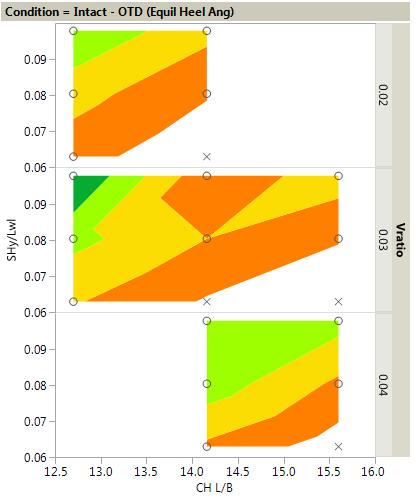
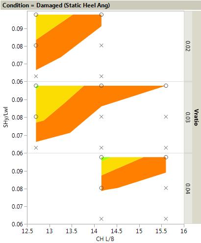
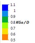
60 Figure 4-18 Stability Assessment, Feasible Region: KGa/D > 0.5(Hulls 1-3, 7-24) 51

61 4.6 Response Surface Model Using the KGa/D results from executing the DoE through the stability model, statistical relationships are developed to guide rule-of thumb processes and early-stage design efforts. First, functions for intact and damaged conditions listed in Table 4-18 are fit to the Hull 1, 1a, and 1b data pictured in Figure The effect of longitudinal side hull position, SH X, was not significant enough as shown in Figure 4-13, especially in damaged condition, and a function for KGa/D could not be determined. Next using hulls 1 and 7-24, KGa/D as a function of SH Y/Lwl, (L/B) CH, and Vratio for intact and damaged conditions were determined. Summary statistics are listed in Table 4-19, actual v. predicted values are plotted in Figure 4-19, and the formulas are listed in Table Examining these functions will guide additional work to determine areas of the DoE to increase point density and further improve the functions. Table 4-18 KGa/D functions of (B/T) SH, Hulls 1,1a, and 1b at Intact and Damaged Conditions Intact (A1/A2): KGa/D ( (B/T) SH) = *(B/T) SH *(B/T) SH 2 Intact-OTD (Equil. HA): KGa/D ( (B/T) SH) = *Log( (B/T) SH) *Log( (B/T) SH) 2 Damaged (Static HA): KGa/D ( (B/T) SH) = *(B/T) SH *(B/T) SH 2 Table 4-19 KGa/D Function Statistics Summary, Hulls 1 and 7-24 Condition R Sq RMSE Residual Range Intact (A1/A2) / Intact-OTD (Equil. HA) / Damaged (Static HA) / Intact (A1/A2) Intact-OTD (Equil. HA) Damaged (Static HA) Figure 4-19 KGa/D Function Actual v. Predicted, Hulls 1 and 7-24 Table 4-20 KGa/D Functions of Hulls 1 and 7 24 at Intact and Damaged Conditions Intact (A1/A2): KGa/D ( SH Y/Lwl, (L/B) CH, Vratio ) = *Vratio *(L/B) CH *Vratio*(L/B) CH *SH Y/Lwl *Vratio* SH Y/Lwl *CH L/B*SHy/Lwl) *Vratio *(L/B) CH 52
62 Intact-OTD (Equil. HA): KGa/D ( SH Y/Lwl, (L/B) CH, Vratio ) = *Vratio *(L/B) CH *Vratio*(L/B) CH *SH Y/Lwl *Vratio *(L/B) CH 2 Damaged (Static HA): KGa/D ( SH Y/Lwl, (L/B) CH, Vratio ) = *Vratio *(L/B) CH *SH Y/Lwl *Vratio*SH Y/Lwl *(L/B) CH* SH Y/Lwl *(L/B) CH * (SH Y/Lwl) 2 The damaged condition is the limiting KGa for all hulls except for hull 20 which had the smallest SH, largest L/B, and SH position T1 closest to the CH. In this case the intact KGa/D for hull 20 was 0.02 less than the damage KGa/D. Since this discrepancy for hull 20 is small, we can use the damage KGa/D function as an overall function to determine KGa/D for trimaran configurations similar to the ones used in the DoE. Further by normalizing the KGa/D as function of (B/T) SH by Hull 1, it can be added to the KGa/D as a function of SH Y/Lwl, (L/B) CH, and Vratio for the damaged condition. Equation 4 is the resulting response surface model (RSM). This RSM for KGa/D can be visualized using a series of (L/B) CH v. SH Y/Lwl contour plots shown in Appendix A where discrete values of (B/T) SH and Vratio are used. This RSM has a very good R Squared and RMSE values; however, to maintain valid results given the sparse DoE, care should be taken not to extrapolate the variable values beyond the range examined. The bounds with which this RSM maintains applicability are detailed in Table Additionally, these bounds and DoE points are plotted on the contours in Appendix A. KGa/D ( (B/T) SH, SH Y/Lwl, (L/B) CH, Vratio ) = *(B/T) SH *(B/T) SH *Vratio *(L/B) CH *SH Y/Lwl *Vratio*SH Y/Lwl *(L/B) CH* SH Y/Lwl *(L/B) CH * (SH Y/Lwl) 2 Equation 4 Table 4-21 Valid Bounds for Variables in KGa/D RSM Variable Min Max (B/T) SH SH Y/Lwl (L/B) CH Vratio
63 4.7 Application of Stability RSM to Ship Design With one small exception, the worst damaged condition determined the allowable KG, KGa, for each hull variation and an overall function is established in Equation 4. For these damage conditions, list angle criterion (a) determined the KGa. This is somewhat concerning given the results Peters and Wing (2009) found where the list angle for a damaged monohull shows poor correlation with dynamic stability results summarized in Table 2-5. Performing a similar analysis for a trimaran hull form would enable further insight regarding the usefulness of the list angle criterion (a) as a measure of stability. Surface combatants in navies across the globe are employing more capable topside weapons, radars, and other sensors on surface ships for increased coverage. These systems are often heavier than the systems they re replacing and continue to be mounted up high in the top-level superstructure and on the mast. Placing too many of these systems in these areas will increase the KG. Having knowledge at the concept stage regarding the maximum, allowable KG will guide the design towards a stable ship from the start. The derived function in Equation 4 provides such a rule of thumb, first approach when determining the KGa for a trimaran ship, displacing close to 3,780 mt, during the early-stage design stage. Coupled with displacement, the KG is an important parameter to be considered not only for adequate stability but for seakeeping performance as well. Additionally, Equation 4 can be utilized as a constraint for design space exploration used in the early-stage. In such a formulation, trimaran hull form variations could be examined and optimized for resistance, ship motions, or both. The KGa/D function could be used to determine the infeasible region which are likely to fail an assessment of damaged stability. Similarly, set based methods using ship synthesis models to evaluate the ship systems could benefit from this KGa/D constraint for trimaran damaged stability. To examine the usefulness of Equation 4 and the contours plotted in Appendix A, let s consider a situation where the designer would like to modify the propulsion for the baseline hull. The effect of twin propellers in the center hull is examined rather than one larger propeller in the center hull and two smaller propellers in each side hull. The L/B ratio of the center hull may need to decrease from to accommodate the twin shafts. The baseline design had a 5.5m propeller in the center hull and two 1.05m propellers in each side hull. If the total propeller area is kept constant, two 4.03m propellers would provide similar thrust to the original design. Given a half diameter propeller separation distance, the Bwl of the center hull needs be at least 10.1m. Thus, no change is required from the baseline hull to accommodate two shafts. However, if the designer chose to change the displacement distribution to a smaller side hull, say Vratio = 3%, for improved low-speed resistance then the (L/B) CH would need to decrease to or the SH Y/Lwl would need to increase to 0.084, 0.57m out from its current position. This would maintain the same KGa/D = 0.5 assuming the (B/T) SH remains constant at
64 5 Conclusions: Stability Criteria Adaption for Trimaran After defining a trimaran and giving an overview of its advantages and potential stability concerns under damage, a review of different methods to assess ship stability were examined. These methods include semi-empirical, deterministic criteria relying on quasi-static estimates and probabilistic methods relying mostly on time domain simulations. Additionally, current research was reviewed for total loss of stability (capsize) events of damaged monohulls and parametric roll events of intact trimarans in longitudinal waves. In Chapter 3 intact vessels along the multi-hull continuum with the same displacement and waterplane area were examined. The trimaran hull forms were observed to possess stability qualities between the monohull and catamaran with largely linear trends as displacement was distributed between hulls. A strong dependency is exhibited between side hull displacement and area, A1 as well as side hull displacement and maximum righting arm, GZ. For trimarans, the deck edge submerges at a heel angle around 30 degrees, whereas the monohull and catamaran deck edge submerges at around 50 degrees of heel. Next, a thorough examination of the hydrostatic properties at trim and heel angles for the monohull and 2.5% - 95% - 2.5% trimaran were assessed. Hydrostatic properties were examined for heel angles up to the angle of vanishing stability for bow down and up trim angles. One key observation was the LCF moves towards midships for all trim angles on the monohull and trimaran with side hulls in the aft position, where the LCF moves forward for bow down trim angles and aft for bow up trim angles on the trimaran with mid SH position. This indicates that the stability may be more of a concern for the trimaran with a trim at large heel angle greater than 30 degrees more so than for a monohull. Additionally, it confirms the possibility that the side hull longitudinal position, SH X, may have an impact on transverse stability. Insights gained from the quasi-static estimates determined in Chapter 3 along the multi-hull continuum are used to develop a series of trimarans in Chapter 4. In which further geometric configurations were examined for transverse stability under intact and damaged conditions. Starting from a design concept with multi-mission frigate capability displacing 3,780 mt, 26 subdivided trimaran models were generated and analyzed for published USN transverse stability criteria. The principal and coupled effects of (B/T) SH, SH X, SH Y, (L/B) CH, and Vratio on the intact and damaged stability response were examined through a multi-stage DoE approach. An increase in side hull beam to draft ratio decreases the KGa for the intact condition; however, for intact-otd, and damaged conditions the KGa increases. The KGa increases from aft, L1, to forward, L2, SH position for intact conditions, however for damaged conditions minimal effect is present. As expected, the side hull transverse location SH Y has the most effect KGa followed by (L/B) CH and Vratio for intact and damaged conditions. Using these relationships, a response surface model (RSM) for KGa/D as a function of (B/T) SH, SH Y, (L/B) CH, and Vratio was determined, Within the bounds of applicability, the KGa/D RSM can be used as a rule-of-thumb and optimization constraint for future studies. 55
65 Several tasks for additional work to expand and enhance this thesis are recommended. Adding more trimaran hull form configurations to the DoE would increase the applicability of the RSM and its use in early-stage design. The density of points should be increased in areas where contours aren t well defined in the RSM. Applying probabilistic methods to assess damaged stability of trimarans and compare to deterministic criteria would further necessitate the need to use these methods for naval combatants. Additionally, using probabilistic methods to compare damaged monohull and trimaran vessels would aid in the understanding of their differences in terms of next generation criteria and dynamic stability. 56
66 References Andrews, D.J., 2004a, Architectural Considerations in Trimaran Ship Design UCL, RINA, Design and Operation of Trimaran Ships, London, UK Andrews, D.J., 2004b, Multi-Hulled Vessels, Chapter 46, Ship Design and Construction, Lamb, T. (ed), SNAME, New Jersey Andrews, D.J. and J.W. Zhang, 1995, Trimaran Ships The Configuration for the Frigate of the Future Naval Engineers Journal Ball, R.E, and C.N. Calvano, 1994, Establishing the fundamentals of a surface ship survivability design discipline, Naval Engineers Journal, Vol. 106, No. 1, pp Belenky, V., C. Bassler, and K. Spyrou, 2009, Dynamic Stability Assessment in Early-Stage Ship Design, 10 th International Conference on Stability of Ships and Ocean Vehicles, pp , St. Petersburg Belenky, V. and C. Bassler, 2010, Procedures for Early-Stage Naval Ship Design Evaluation of Dynamic Stability: Influence of the Wave Crest, Naval Engineers Journal, 122(2), pp Boulougouris, E., S. Winnie, and A. Papanikolaou, 2016, Advanced damage stability assessment for surface combatants, Ocean Engineering, Vol. 120, pp Boulougouris, E.K., and A.D. Papanikolaou, 2013, Risk-based design of naval combatants, Ocean Engineering, Vol. 65, pp Boulougouris, E.K., and A.D. Papanikolaou, 2004, Optimization of the survivability of naval ships by genetic algorithms, 3 rd International Euro-Conference on Computer Applications and Information Technology in the Maritime Industries (COMPIT), pp Brown, A.J. and F. Deybach, 1998 Towards a Rational Intact Stability Criteria for Naval Ships, Naval Engineers Journal, American Society of Naval Engineers Brown, A.J., 2015 Multi-Objective Design of a Trimaran Surface Combatant, International Maritime Design Conference (IMDC), Tokyo, Japan Buckley, W. H., 1994, "Stability Criteria: Development of a First Principles Methodology," Fifth International Conference on Stability of Ships and Ocean Vehicles Bulian, G., A. Francescutto and F. Fucile, 2011, Study of trimaran stability in longitudinal waves, Ships and Offshore Structures, 6:4, , DOI: / Doctors, L. J. and R. J Scrace, 2004, Hydrodynamic Interactions Between the Subhulls of a Trimaran During Roll Motion. RINA International Conference on the Design and Operation of Trimaran Ships, London, UK, ISBN
67 DRS Technologies, Inc., 2017, Orca3D Help, orca3d.com/wp-content/uploads/2015/help, Accessed 4 Sept 2017 Dubrovsky, V.A., 2004, Ships with Outriggers, Backbone Publishing Company, Fair Lawn, NJ Dubrovsky V.A. and A.G. Lyakhovitsky, 2001, Multi-Hull Ships, Backbone Publishing Company, Fair Lawn, NJ Egan, G.E., A.V Hattier, and B.L. Hutchinson, 1998, The Alaska RO/RO Passenger Ferry MV Kennicott SNAME Transactions, Vol. 106, pp Francescutto, A. and A. Cardo, 2001, Dynamic Stability and Roll Motion Modelling of Multihulls, FAST, Southampton, UK Fishkis, Y.M., 1976, Research of Stability and Floatability of Twin-Hull Ships, Trans. NTOSP, Vol. 174, p Grafton, T.J., 2007, The Roll Motion of Trimaran Ships, PhD Thesis, University of London Harmsen, E. and M. Krikke, 2000, A probabilistic edamage stability calculation method for naval vessels, International Conference on Stabiliy of Ship and Ocean Vehicles, pp Ikeda, Y., Y. Himeno, and N. Tanaka, 1978, Components of Roll Damping of Ship at Forward Speed, Report of the Department of Naval Architecture, University of Osaka Prefecture, No (see also Ikeda, Y., Y. Himeno, and N. Tanaka (1978), Component of Roll Damping of Ship at Forward Speed, J. Society of Naval Architects of Japan, 143, pp , in Japanese) Ikeda, Y. and T. Katayama, 2000, Roll Damping Prediction Method for a High-Speed Planing Craft, Proc. 7th Intl. Conf. on the Stability of Ships and Ocean Vehicles, Tasmania, Australia Katayama, T., T. Taniguchi, and M. Kotaki, 2008, A Study on Viscous Effects of Roll Damping of a High-Speed Catamaran and a High-Speed Trimaran, Proc. 6th Osaka Colloquium on Seakeeping and Stability of Ships, Osaka, Japan Katayama, T., M. Kotaki, and Y. Ikeda, 2011, A Study on the Characteristics of Roll Damping of Multi-Hull Vessels, Contemporary Ideas on Ship Stability and Capsizing in Waves, Volume 97 of the series Fluid Mechanics and Its Applications, pp MARIN, 2017, FREDYN: Seakeeping and manoeuvering behaviour of ships in waves and wind, Accessed 30 August 2017 MoD, 2014, Defence Standard Part 4, Safety and Environmental Protection, Ship, Chapter 3: Stability 58
68 Manzitti, T., K. Neild, L. Pomeroy, M. Sweet, H. Thompson, 2016, Design Report Frigate Trimaran (FFGT2), Ocean Engineering Design Project, Department of Aerospace and Ocean Engineering, Virginia Tech, Blacksburg, VA Naval Sea Systems Command (NAVSEA), 2016, Design Practices And Criteria For U.S. Navy Surface Ship Stability And Reserve Buoyancy, Technical Publication T9070-AF-DPC-010/079-1, U.S. Navy NATO Standardization Agency (NSA), 2017, Naval Ship Code. Allied Naval Engineering Publication, ANEP-77, Ed. F, ver.2. Brussels Ordonez, L.A., 1995, Exploration of the Damage Stability Characteristics of the Trimaran Surface Combatant, Naval Postgraduate School Master s Thesis Pawlowski, M., 1999, Subdivision of RO/RO Ships for Enhanced Safety in the Damaged Condition Marine Technology, Vol. 36, No. 4, pp Peters, A.J., and D. Wing, 2009, "Stability Criteria Evaluation and Performance based criteria development for damaged Naval Vessels" 10th International Conference on Stability of Ships and Ocean Vehicles, pp , St. Petersburg Przemieniecki, J.S., 1994, Mathematical methods in defense analyses, Education Series of American Institute of Aeronautics and Astronatics (ISBN ) Riola, J.M., R. Perez, and B. Rodriguez, Damaged warship stability tests based on ANEP-77: A case study for F-110, Ship Science & Technology, Vol. 10, no. 10, pp , January 2017 Ross, C.T.F., S. Stothard and A. Slaney, 2000, Damage Stability Characteristics of Model RO/RO Ferries, Marine Technology, Vol. 37, No. 1, pp Said, M.O., 1995, Theory and practice of total ship survivability for ship design, Naval Engineers Journal, Vol. 107, No. 4, pp Sarchin, T.H. and L.L. Goldberg, 1962, Stability and Buoyancy Criteria for U.S. Naval Surface Ships, SNAME Transactions, Vol. 70. Spyrou, K.J. and I. Roupas, 2007, Damaged-ship survivability: A step beyond Wendel, International Shipbuilding Progress 54, pp Surko, S.W., 1994, An assessment of current warship damaged stability criteria, Naval Engineers Journal, Vol. 106, No. 2, pp Vassalos, D., A. York, A. Jasionowski, M. Kanerva, and A. Scott, 2007, Design implications of the new harmonized probabilistic damage stability regulations International Shipbuilding Progress 54, pp
69 Vassalos, D., and L. Guarin, 2009, Designing for Damage Stability and Survivability Contemporary Developments and Implementation Ship Science & Technology, Vol. 3, No. 5 Wendel, K., 1968, Subdivision of ships, in: Diamond Jubilee International Meeting, New York, June pp Zhang, J-W. and D. J Andrews, 1999, Roll Damping Characteristics o f a Trimaran Displacement Ship. International Shipbuilding Progress, Volume 46, No 448 Zubaly, R.B., 1996, Applied Naval Architecture, Cornell Maritime Press, Inc. Figure References Figure 1-5, Zubaly, R.G., 1996, Applied Naval Architecture, Cornell Maritime Press, Inc., pp. 63, Fair use; determination attached Figure 1-6, Zubaly, R.G., 1996, Applied Naval Architecture, Cornell Maritime Press, Inc., pp. 113, Fair use; determination attached Figure 1-7, Grafton, T.J., 2007, The Roll Motion of Trimaran Ships, PhD Thesis, University of London, pp. 74, Fair use; determination attached Figure 2-1, Naval Sea Systems Command (NAVSEA), 2016, Design Practices And Criteria For U.S. Navy Surface Ship Stability And Reserve Buoyancy, Technical Publication T9070-AF-DPC-010/079-1, U.S. Navy, pp. 8-2, Fair use; determination attached Figure 2-2, Naval Sea Systems Command (NAVSEA), 2016, Design Practices And Criteria For U.S. Navy Surface Ship Stability And Reserve Buoyancy, Technical Publication T9070-AF-DPC-010/079-1, U.S. Navy, pp. 8-13, Fair use; determination attached Figure 2-3, Bulian, G., A. Francescutto and F. Fucile, 2011, Study of trimaran stability in longitudinal waves, Ships and Offshore Structures, 6:4, , DOI: / , pp. 268, Fair use; determination attached Figure 2-4 Bulian, G., A. Francescutto and F. Fucile, 2011, Study of trimaran stability in longitudinal waves, Ships and Offshore Structures, 6:4, , DOI: / , pp. 270, Fair use; determination attached Figure 4-1, Manzitti, T., K. Neild, L. Pomeroy, M. Sweet, H. Thompson, 2016, Design Report Frigate Trimaran (FFGT2), Ocean Engineering Design Project, Department of Aerospace and Ocean Engineering, Virginia Tech, Blacksburg, VA, pp. 2, Fair use; determination attached 60
 SH = 0.4, Vratio = 0.03 (B/T) SH = 0.")
 SH = 0.64, Vratio = 0.03 (B/T) SH = 0.")
70 Appendix A KGa/D RSM Visualized through Contour Plots (B/T) SH = 0.4, Vratio = 0.02 (B/T) SH = 0.4, Vratio = 0.03 (B/T) SH = 0.4, Vratio = 0.04 (B/T) SH = 0.64, Vratio = 0.02 (B/T) SH = 0.64, Vratio = 0.03 (B/T) SH = 0.64, Vratio =


 SH = 1.04 62")
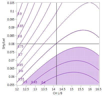
71 (B/T) SH = 0.88, Vratio = 0.02 (B/T) SH = 0.88, Vratio = 0.03 (B/T) SH = 0.88, Vratio = 0.04 (B/T) SH = 1.12, Vratio = 0.02 (B/T) SH = 1.12, Vratio = 0.03 (B/T) SH = 1.12, Vratio =
Ship Stability. Ch. 8 Curves of Stability and Stability Criteria. Spring Myung-Il Roh
 Lecture Note of Naval Architectural Calculation Ship Stability Ch. 8 Curves of Stability and Stability Criteria Spring 2016 Myung-Il Roh Department of Naval Architecture and Ocean Engineering Seoul National
S0300-A6-MAN-010 CHAPTER 2 STABILITY
 CHAPTER 2 STABILITY 2-1 INTRODUCTION This chapter discusses the stability of intact ships and how basic stability calculations are made. Definitions of the state of equilibrium and the quality of stability
Comparative Stability Analysis of a Frigate According to the Different Navy Rules in Waves
 Comparative Stability Analysis of a Frigate According to the Different Navy Rules in Waves ABSTRACT Emre Kahramano lu, Technical University, emrek@yildiz.edu.tr Hüseyin Y lmaz,, hyilmaz@yildiz.edu.tr Burak
IMO REVISION OF THE INTACT STABILITY CODE. Proposal of methodology of direct assessment for stability under dead ship condition. Submitted by Japan
 INTERNATIONAL MARITIME ORGANIZATION E IMO SUB-COMMITTEE ON STABILITY AND LOAD LINES AND ON FISHING VESSELS SAFETY 49th session Agenda item 5 SLF 49/5/5 19 May 2006 Original: ENGLISH REVISION OF THE INTACT
SAMPLE MAT Proceedings of the 10th International Conference on Stability of Ships
 and Ocean Vehicles 1 Application of Dynamic V-Lines to Naval Vessels Matthew Heywood, BMT Defence Services Ltd, mheywood@bm tdsl.co.uk David Smith, UK Ministry of Defence, DESSESea-ShipStab1@mod.uk ABSTRACT
Sample Application of Second Generation IMO Intact Stability Vulnerability Criteria as Updated during SLF 55
 1 Sample Application of Second Generation IMO Intact Stability Vulnerability Criteria as Updated during SLF 55 Clève Wandji, Bureau Veritas Philippe Corrignan, Bureau Veritas ABSTRACT A second generation
Subj: Explanation of Upper Level Capacity and Stability Characteristics for Rolling Boat, Inc. Vessels.
 23 Apr, 2009 From: Tullio Celano III P.E. To: Underwriters of Rolling Boat, Inc. Via: Phil Kazmierowicz, President, Rolling Boat, Inc. Subj: Explanation of Upper Level Capacity and Stability Characteristics
RULES FOR THE CONSTRUCTION AND CLASSIFICATION OF SHIPS IDENTIFIED BY THEIR MISSIONS CHAPTERS SCOPE
 PART II RULES FOR THE CONSTRUCTION AND CLASSIFICATION OF SHIPS IDENTIFIED BY THEIR MISSIONS TITLE 12 CONTAINER SHIPS SECTION 1 NAVAL ARCHITECTURE CHAPTERS A SCOPE B DOCUMENTS, REGULATIONS AND STANDARDS
for Naval Aircraft Operations
 Seakeeping Assessment of Large Seakeeping Assessment of Large Trimaran Trimaran for Naval Aircraft Operations for Naval Aircraft Operations Presented by Mr. Boyden Williams, Mr. Lars Henriksen (Viking
A New Approach to the Derivation of V-Line Criteria for a Range of Naval Vessels
 A New Approach to the Derivation of V-Line Criteria for a Range of Naval Vessels Andrew Peters 1, Rick Goddard 2 and Nick Dawson 1 1. QinetiQ, Haslar Marine Technology Park (UK) 2. Steller Systems Ltd.,
RULES PUBLICATION NO. 86/P EXPLANATORY NOTES TO SOLAS CONVENTION AND DIRECTIVE 2003/25/EC STABILITY AND SUBDIVISION REQUIREMENTS
 RULES PUBLICATION NO. 86/P EXPLANATORY NOTES TO SOLAS CONVENTION AND DIRECTIVE 2003/25/EC STABILITY AND SUBDIVISION REQUIREMENTS 2011 Publications P (Additional Rule Requirements) issued by Polski Rejestr
Rules for Classification and Construction Additional Rules and Guidelines
 VI Rules for Classification and Construction Additional Rules and Guidelines 11 Other Operations and Systems 6 Guidelines for the Preparation of Damage Stability Calculations and Damage Control Documentation
MSC Guidelines for Review of Stability for Sailing Catamaran Small Passenger Vessels (T)
") K.B. FERRIE, CDR, Chief, Hull Division References: a. 46 CFR Subchapter T, Parts 178, 179 b. 46 CFR Subchapter S, Parts 170, 171 c. Marine Safety Manual (MSM), Vol. IV d. Navigation and Vessel Circular
K.B. FERRIE, CDR, Chief, Hull Division References: a. 46 CFR Subchapter T, Parts 178, 179 b. 46 CFR Subchapter S, Parts 170, 171 c. Marine Safety Manual (MSM), Vol. IV d. Navigation and Vessel Circular
CLASS 1E 8 SMOOTH WATERS OPERATIONS 8
 Table of Contents INSTRUCTION TO MASTERS SAFETY INFORMATION 3 STABILITY BOOK TO BE KEPT ON VESSEL 3 LOADING CONDITIONS 3 ASPECTS OF LOADING 3 PASSENGER PARTICULARS 3 HYDROSTATIC AND KN VALUES 4 EXCESS
STABILITY CRITERIA EVALUATION AND PERFORMANCE BASED CRITERIA DEVELOPMENT FOR DAMAGED NAVAL VESSELS
 10 th International Conference 155 STABILITY CRITERIA EVALUATION AND PERFORMANCE BASED CRITERIA DEVELOPMENT FOR DAMAGED NAVAL VESSELS Andrew J. Peters QinetiQ, Haslar Marine Technology Park, (UK) David
Marine Kit 4 Marine Kit 4 Sail Smooth, Sail Safe
 Marine Kit 4 Marine Kit 4 Sail Smooth, Sail Safe Includes Basic ship Terminologies and Investigation Check list Index 1. Ship Terminology 03 2. Motions of a Floating Body...09 3. Ship Stability.10 4. Free
Application and Development of Multi-Hulls
 April 20, 204 Application and Development of Multi-Hulls a) Balt Techno Prom, St.Petersburg, Russia Victor A. Dubrovsky, a,* *Corresponding author: multi-hulls@yandex.ru Paper History Received: 8-January-204
WATERTIGHT INTEGRITY. Ship is divided into watertight compartments by means of transverse and longitudinal bulkheads bulkheads.
 Damage Stability WATERTIGHT INTEGRITY Ship is divided into watertight compartments by means of transverse and longitudinal bulkheads bulkheads. When a watertight compartment (or a group of compartments)
ANNEX 5 IMO MARINE CASULATY AND INCIDENT REPORT DAMAGE CARDS* AND INTACT STABILITY CASUALTY RECORDS
 ANNEX 5 IMO MARINE CASUATY AND INCIDENT REPORT DAMAGE CARDS* AND INTACT STABIITY CASUATY RECORDS Statistics of damaged ships and of intact stability casualties are important to the work of the Organization
RESOLUTION MSC.141(76) (adopted on 5 December 2002) REVISED MODEL TEST METHOD UNDER RESOLUTION 14 OF THE 1995 SOLAS CONFERENCE
 (adopted on 5 December 2002) REVISED MODEL TEST METHOD UNDER RESOLUTION 14 OF THE 1995 SOLAS CONFERENCE") MSC 76/23/Add.1 RESOLUTION MSC.141(76) THE MARITIME SAFETY COMMITTEE, RECALLING Article 38(c) of the Convention on the International Maritime Organization concerning the functions of the Committee, RECALLING
MSC 76/23/Add.1 RESOLUTION MSC.141(76) THE MARITIME SAFETY COMMITTEE, RECALLING Article 38(c) of the Convention on the International Maritime Organization concerning the functions of the Committee, RECALLING
INCLINOMETER DEVICE FOR SHIP STABILITY EVALUATION
 Proceedings of COBEM 2009 Copyright 2009 by ABCM 20th International Congress of Mechanical Engineering November 15-20, 2009, Gramado, RS, Brazil INCLINOMETER DEVICE FOR SHIP STABILITY EVALUATION Helena
RESOLUTION MSC.235(82) (adopted on 1 December 2006) ADOPTION OF THE GUIDELINES FOR THE DESIGN AND CONSTRUCTION OF OFFSHORE SUPPLY VESSELS, 2006
 (adopted on 1 December 2006) ADOPTION OF THE GUIDELINES FOR THE DESIGN AND CONSTRUCTION OF OFFSHORE SUPPLY VESSELS, 2006") MSC 82/24/Add.2 RESOLUTION MSC.235(82) CONSTRUCTION OF OFFSHORE SUPPLY VESSELS, 2006 THE MARITIME SAFETY COMMITTEE, RECALLING Article 28(b) of the Convention on the International Maritime Organization
MSC 82/24/Add.2 RESOLUTION MSC.235(82) CONSTRUCTION OF OFFSHORE SUPPLY VESSELS, 2006 THE MARITIME SAFETY COMMITTEE, RECALLING Article 28(b) of the Convention on the International Maritime Organization
STABILITY OF MULTIHULLS Author: Jean Sans
 STABILITY OF MULTIHULLS Author: Jean Sans (Translation of a paper dated 10/05/2006 by Simon Forbes) Introduction: The capsize of Multihulls requires a more exhaustive analysis than monohulls, even those
An Investigation into the Capsizing Accident of a Pusher Tug Boat
 An Investigation into the Capsizing Accident of a Pusher Tug Boat Harukuni Taguchi, National Maritime Research Institute (NMRI) taguchi@nmri.go.jp Tomihiro Haraguchi, National Maritime Research Institute
This lesson will be confined to the special case of ships at rest in still water. Questions of motions resulting from waves are not considered at
 STATIC STABILITY When we say a boat is stable we mean it will (a) float upright when at rest in still water and (b) return to its initial upright position if given a slight, temporary deflection to either
CERTIFICATES OF COMPETENCY IN THE MERCHANT NAVY MARINE ENGINEER OFFICER
 CERTIFICATES OF COMPETENCY IN THE MERCHANT NAVY MARINE ENGINEER OFFICER EXAMINATIONS ADMINISTERED BY THE SCOTTISH QUALIFICATIONS AUTHORITY ON BEHALF OF THE MARITIME AND COASTGUARD AGENCY STCW 95 CHIEF
ITTC Recommended Procedures and Guidelines
 Page 1 of 7 Table of Contents 2 1. PURPOSE... 2 2. PARAMETERS... 2 2.2. General Considerations... 2 2.3. Special Requirements for Ro-Ro Ferries... 3 3.3. Instrumentation... 4 3.4. Preparation... 5 3.5.
G.L.M. : the on-board stability calculator... DEMONSTRATION OPERATOR S MANUAL
 General Load Monitor G.L.M. : the on-board stability calculator... DEMONSTRATION OPERATOR S MANUAL Distributed by: DESIGN SYSTEMS & TECHNOLOGIES 150 Rue de Goa, 06600 Antibes, France tel +33.4.92 91 13
SECOND ENGINEER REG III/2 NAVAL ARCHITECTURE
 SECOND ENGINEER REG III/2 NAVAL ARCHITECTURE LIST OF TOPICS A B C D E F G H I J Hydrostatics Simpson's Rule Ship Stability Ship Resistance Admiralty Coefficients Fuel Consumption Ship Terminology Ship
Ship Stability September 2013 Myung-Il Roh Department of Naval Architecture and Ocean Engineering Seoul National University
 Planning Procedure of Naval Architecture and Ocean Engineering Ship Stability September 2013 Myung-Il Roh Department of Naval Architecture and Ocean Engineering Seoul National University 1 Ship Stability
Understanding How Excessive Loading Lead to a Capsize with Loss of Life Can Help Avoid Future Tragedies
 Understanding How Excessive Loading Lead to a Capsize with Loss of Life Can Help Avoid Future Tragedies By Dave Gerr, CEng FRINA 2012 Dave Gerr fter sailing out to watch the fireworks on July 4th, 2012,
GUIDELINES ON OPERATIONAL INFORMATION FOR MASTERS IN CASE OF FLOODING FOR PASSENGER SHIPS CONSTRUCTED BEFORE 1 JANUARY 2014 *
 E 4 ALBERT EMBANKMENT LONDON SE1 7SR Telephone: +44 (0)20 7735 7611 Fax: +44 (0)20 7587 3210 MSC.1/Circ.1589 24 May 2018 GUIDELINES ON OPERATIONAL INFORMATION FOR MASTERS IN CASE OF FLOODING FOR PASSENGER
SHIP FORM DEFINITION The Shape of a Ship
 SHIP FORM DEFINITION The Shape of a Ship The Traditional Way to Represent the Hull Form A ship's hull is a very complicated three dimensional shape. With few exceptions an equation cannot be written that
DAMAGE STABILITY TESTS OF MODELS REPRESENTING RO-RC) FERRIES PERFORMED AT DMI
 FERRIES PERFORMED AT DMI") TECHNISCHE UNIVERSITET laboratoriurn vow Scheepshydromechareba slechlef Meketweg 2, 2628 CD. Delft Tel.: 015-788873 - Fax 015-781838 DAMAGE STABILITY TESTS OF MODELS REPRESENTING RO-RC) FERRIES PERFORMED
TECHNISCHE UNIVERSITET laboratoriurn vow Scheepshydromechareba slechlef Meketweg 2, 2628 CD. Delft Tel.: 015-788873 - Fax 015-781838 DAMAGE STABILITY TESTS OF MODELS REPRESENTING RO-RC) FERRIES PERFORMED
Small Ro/Pax Vessel Stability Study
 Small Ro/Pax Vessel Stability Study Primary author: Henrik Erichsen, M.Sc., Lead Technical Specialist in Charge, Lloyd s Register EMEA Co-authors: Hans Otto Kristensen, Director, M.Sc. FRINA and MSNAME,
CRITERIA OF BOW-DIVING PHENOMENA FOR PLANING CRAFT
 531 CRITERIA OF BOW-DIVING PHENOMENA FOR PLANING CRAFT Toru KATAYAMA, Graduate School of Engineering, Osaka Prefecture University (Japan) Kentarou TAMURA, Universal Shipbuilding Corporation (Japan) Yoshiho
TRIMARAN HULL DESIGN FOR FAST FERRY APPLICATIONS
 TRIMARAN HULL DESIGN FOR FAST FERRY APPLICATIONS Stefano Brizzolara, Marco Capasso, Marco Ferrando, Carlo Podenzana Bonvino Dept. of Naval Architecture and Marine Technologies, Univ. of Genova, Italy;
Chapter 2 Hydrostatics and Control
 Chapter 2 Hydrostatics and Control Abstract A submarine must conform to Archimedes Principle, which states that a body immersed in a fluid has an upward force on it (buoyancy) equal to the weight of the
Multihull Preliminary Stability Estimates are Fairly Accurate
 Multihull Design (Rev. A) 45 APPENDIX A ADDITIONAL NOTES ON MULTIHULL DESIGN MULTIHULL STABILITY NOTES Multihull stability is calculated using exactly the same method as described in Westlawn book 106,
A STUDY ON FACTORS RELATED TO THE CAPSIZING ACCIDENT OF A FISHING VESSEL RYUHO MARU No.5
 8 th International Conference on 49 A STUDY ON FACTORS RELATED TO THE CAPSIZING ACCIDENT OF A FISHING VESSEL RYUHO MARU No.5 Harukuni Taguchi, Shigesuke Ishida, Iwao Watanabe, Hiroshi Sawada, Masaru Tsujimoto,
Aircraft carrier stability in damaged condition
 Aircraft carrier stability in damaged condition V. Slapničar University of Zagreb, Faculty of Mechanical Engineering and Naval Architecture, Zagreb, Croatia B. Ukas Saipem S.p.A, Milano, Italy ABSTRACT:
Three New Concepts of Multi-Hulls
 Three New Concepts of Multi-Hulls Victor A. Dubrovsky Independent designer, Russian Federation 114-71 Budapeshtskaja Str, St.Petersburg, 192283, Russian Federation Multi-hulls@yandex.ru Abstract Many multi-hull
Abstract. 1 Introduction
 A computational method for calculatingthe instantaneous restoring coefficients for a ship moving in waves N. El-Simillawy College of Engineering and Technology, Arab Academyfor Science and Technology,
MSC Guidelines for the Submission of Stability Test (Deadweight Survey or Inclining Experiment) Results
 Results") S. E. HEMANN, CDR, Chief, Hull Division References a. 46 CFR 170, Subpart F Determination of Lightweight Displacement and Centers of Gravity b. NVIC 17-91 Guidelines for Conducting Stability Tests c. ASTM
S. E. HEMANN, CDR, Chief, Hull Division References a. 46 CFR 170, Subpart F Determination of Lightweight Displacement and Centers of Gravity b. NVIC 17-91 Guidelines for Conducting Stability Tests c. ASTM
SOFTWARE. Sesam user course. 12 May 2016 HydroD Hydrostatics & Stability. Ungraded SAFER, SMARTER, GREENER DNV GL 2016
 SOFTWARE Sesam user course DNV GL 1 SAFER, SMARTER, GREENER Scope of presentation Describe features & commands for performing a hydrostatic analysis, and their concepts Analysis setup Code-checking Reporting
Investigation of the Intact Stability Accident of the Multipurpose Vessel MS ROSEBURG
 Proceedings of the 12th International Conference on the Stability of Investigation of the Intact Stability Accident of the Multipurpose Vessel MS ROSEBURG Adele Lübcke, Institute of Ship Design and Ship
A STUDY OF THE LOSSES AND INTERACTIONS BETWEEN ONE OR MORE BOW THRUSTERS AND A CATAMARAN HULL
 A STUDY OF THE LOSSES AND INTERACTIONS BETWEEN ONE OR MORE BOW THRUSTERS AND A CATAMARAN HULL L Boddy and T Clarke, Austal Ships, Australia SUMMARY CFD analysis has been conducted on a 100m catamaran hull
The salient features of the 27m Ocean Shuttle Catamaran Hull Designs
 The salient features of the 27m Ocean Shuttle Catamaran Hull Designs The hull form is a semi-planing type catamaran. It employs a combination of symmetrical and asymmetrical sponson shapes, thereby combining
MSC Guidelines for Review of Stability for Towing Vessels (M)
") S. E. HEMANN, CDR, Chief, Hull Division References Contact Information a. 46 CFR Subchapter M, Part 144 b. 46 CFR Subchapter S, Parts 170, 173 c. Navigation and Vessel Circular No. 17-91, CH 1, Guidelines
S. E. HEMANN, CDR, Chief, Hull Division References Contact Information a. 46 CFR Subchapter M, Part 144 b. 46 CFR Subchapter S, Parts 170, 173 c. Navigation and Vessel Circular No. 17-91, CH 1, Guidelines
10 December 2010 GUIDANCE FOR WATERTIGHT DOORS ON PASSENGER SHIPS WHICH MAY BE OPENED DURING NAVIGATION
 E 4 ALBERT EMBANKMENT LONDON SE1 7SR Telephone: +44 (0)20 7735 7611 Fax: +44 (0)20 7587 3210 Ref. T4/3.01 MSC.1/Circ.1380 10 December 2010 GUIDANCE FOR WATERTIGHT DOORS ON PASSENGER SHIPS WHICH MAY BE
Application of IMO Second Generation Intact Stability Criteria for Dead Ship Condition to Small Fishin Vessels
 Application of IMO Second Generation Intact Stability Criteria for Dead Ship Condition to Small FishinVessels Francisco Mata-Álvarez-Santullano, Maritime Accident and Incident Investigations Standing Commission,
OVERALL STABILITY 4.1 External Forces Acting on a Vessel In Chapter 4 we will study five areas:
 OVERALL STABILITY 4.1 External Forces Acting on a Vessel In Chapter 4 we will study five areas: 1. The concept of a ship s Righting Moment (RM), the chief measure of stability. 2. KG and TCG changes and
ITTC Recommended Procedures and Guidelines
 Page 1 of 6 Table of Contents 1. PURPOSE...2 2. PARAMETERS...2 2.1 General Considerations...2 3 DESCRIPTION OF PROCEDURE...2 3.1 Model Design and Construction...2 3.2 Measurements...3 3.5 Execution of
The OTSS System for Drift and Response Prediction of Damaged Ships
 The OTSS System for Drift and Response Prediction of Damaged Ships Shoichi Hara 1, Kunihiro Hoshino 1,Kazuhiro Yukawa 1, Jun Hasegawa 1 Katsuji Tanizawa 1, Michio Ueno 1, Kenji Yamakawa 1 1 National Maritime
Review of regulatory framework of Damage Stability of Dry Cargo and Passenger Ships
 Review of regulatory framework of Damage Stability of Dry Cargo and Passenger Ships Two main categories of regulatory concepts and methodologies for the assessment of ship s damage stability are nowadays
Abstract. 1 Introduction
 Buoyancy and strength of existing bulk carriers in flooded conditions J. Jankowski, M. Bogdaniuk, T. Dobrosielski Polski Rejestr Statkow, Gdansk, Poland Email: tk@prs.gda.pl Abstract Bulk carriers have
FUZZY MONTE CARLO METHOD FOR PROBABILITY OF CAPSIZING CALCULATION USING REGULAR AND NON-REGULAR WAVE
 Tomasz Hinz, Polish Registry of Shipping;Tomasz.Hinz@prs.pl Jerzy Matusiak, Aalto University School of Science and Technology FUZZY MONTE CARLO METHOD FOR PROBABILITY OF CAPSIZING CALCULATION USING REGULAR
DESIGN DATA SHEET DDS STABILITY AND BUOYANCY OF U.S. NAVAL SURFACE SHIPS DEPARTMENT OF THE NAVY
 DESIGN DATA SHEET DDS 079-1 STABILITY AND BUOYANCY OF U.S. NAVAL SURFACE SHIPS DEPARTMENT OF THE NAVY This document replaces the DDS 079-1, dated 1 August 1975 i APPROVAL PAGE DESIGN DATA SHEET DDS 079-1
Dynamic Component of Ship s Heeling Moment due to Sloshing vs. IMO IS-Code Recommendations
 International Journal on Marine Navigation and Safety of Sea Transportation Volume 4 Number 3 September 2010 Dynamic Component of Ship s Heeling Moment due to Sloshing vs. IMO IS-Code Recommendations P.
ISSN: ISO 9001:2008 Certified International Journal of Engineering Science and Innovative Technology (IJESIT) Volume 2, Issue 4, July 2013
 Volume 2, Issue 4, July 2013") A Comparison of Hull Resistances of a Mono-Hull and A SWATH Craft Josip Medaković, Ban Dario, Branko Blagojević University of Split, FESB, Department of Mechanical Engineering and Naval Architecture, 21000
A Comparison of Hull Resistances of a Mono-Hull and A SWATH Craft Josip Medaković, Ban Dario, Branko Blagojević University of Split, FESB, Department of Mechanical Engineering and Naval Architecture, 21000
RESOLUTION MSC.429(98) (adopted on 9 June 2017) REVISED EXPLANATORY NOTES TO THE SOLAS CHAPTER II-1 SUBDIVISION AND DAMAGE STABILITY REGULATIONS
 (adopted on 9 June 2017) REVISED EXPLANATORY NOTES TO THE SOLAS CHAPTER II-1 SUBDIVISION AND DAMAGE STABILITY REGULATIONS") Annex 12, page 1 ANNEX 12 RESOLUTION MSC.429(98) (adopted on 9 June 2017) THE MARITIME SAFETY COMMITTEE, RECALLING Article 28(b) of the Convention on the International Maritime Organization concerning
Annex 12, page 1 ANNEX 12 RESOLUTION MSC.429(98) (adopted on 9 June 2017) THE MARITIME SAFETY COMMITTEE, RECALLING Article 28(b) of the Convention on the International Maritime Organization concerning
Experimental Study on the Large Roll Motion of a ROPAX Ship in the Following and Quartering Waves
 Experimental Study on the Large Roll Motion of a ROPAX Ship in the Following and Quartering Waves Sun Young Kim, Nam Sun Son, Hyeon Kyu Yoon Maritime & Ocean Engineering Research Institute, KORDI ABSTRACT
Dynamic Stability of Ships in Waves
 Gourlay, T.P. & Lilienthal, T. 2002 Dynamic stability of ships in waves. Proc. Pacific 2002 International Maritime Conference, Sydney, Jan 2002. ABSTRACT Dynamic Stability of Ships in Waves Tim Gourlay
Deepwater Floating Production Systems An Overview
 Deepwater Floating Production Systems An Overview Introduction In addition to the mono hull, three floating structure designs Tension leg Platform (TLP), Semisubmersible (Semi), and Truss Spar have been
MSC Guidelines for Review of Cargo and Miscellaneous Vessel Stability (Subchapter I)
") S. E. HEMANN, CDR, Chief, Hull Division Purpose The purpose of this Plan Review Guideline is to provide the submitter with general guidance and information for the preparation and submission of stability
S. E. HEMANN, CDR, Chief, Hull Division Purpose The purpose of this Plan Review Guideline is to provide the submitter with general guidance and information for the preparation and submission of stability
Stability Analysis of a Tricore
 Stability Analysis of a Tricore C. M. De Marco Muscat-Fenech, A.M. Grech La Rosa AbstractThe application of stability theory has led to detailed studies of different types of vessels; however, the shortage
Shallow-Draft Ro-Pax Ships for Various Cargos and Short Lines
 Journal of Water Resources and Ocean Science 2017; 6(5): 65-70 http://www.sciencepublishinggroup.com/j/wros doi: 10.11648/j.wros.20170605.12 ISSN: 2328-7969 (Print); ISSN: 2328-7993 (Online) Shallow-Draft
Dynamic Criteria 3rd June 2005
 Dynamic Intact Stability Criteria Scope. General The aim of this report is to introduce dynamic criteria for the intact stability of ships which cover the phenomena of parametric roll and pure loss of
MSC/Circular.649 International Convention for the Safety of Life at Sea, 1974, as amended (Adopted on 8 June 1994)
") Sivu 1/8 Lloyd's Register Rulefinder 2016 - Version 9.25 MSC/Circular.649 International Convention for the Safety of Life at Sea, 1974, as amended (Adopted on 8 June 1994) MSC/Circular.649 International
Sivu 1/8 Lloyd's Register Rulefinder 2016 - Version 9.25 MSC/Circular.649 International Convention for the Safety of Life at Sea, 1974, as amended (Adopted on 8 June 1994) MSC/Circular.649 International
EN400 LAB #2 PRELAB. ARCHIMEDES & CENTER of FLOTATION
 EN400 LAB #2 PRELAB ARCHIMEDES & CENTER of FLOTATION Instructions: 1. The prelab covers theories that will be examined experimentally in this lab. 2. The prelab is to be completed and handed in to your
ITTC Recommended Procedures Testing and Extrapolation Methods Loads and Responses, Seakeeping Experiments on Rarely Occurring Events
 Loads and Responses, Seakeeping Page 1 of 5 CONTENTS 1. PURPOSE OF PROCEDURE 2. STANDARDS FOR EXPERIMENTS ON RARELY OCCURRING EVENTS 2.1 Previous Recommendations of ITTC 2.2 Model Design and Construction
A Study on Roll Damping of Bilge Keels for New Non-Ballast Ship with Rounder Cross Section
 International Ship Stability Workshop 2013 1 A Study on Roll Damping of Bilge Keels for New Non-Ballast Ship with Rounder Cross Section Tatsuya Miyake and Yoshiho Ikeda Department of Marine System Engineering,
The Usage of Propeller Tunnels For Higher Efficiency and Lower Vibration. M. Burak Şamşul
 The Usage of Propeller Tunnels For Higher Efficiency and Lower Vibration M. Burak Şamşul ITU AYOC 2014 - Milper Pervane Teknolojileri Company Profile MILPER is established in 2011 as a Research and Development
Safety practices related to small fishing vessel stability
 18 The vessel s centre of gravity (G) has a distinct effect on the righting lever (GZ) and consequently the ability of a vessel to return to the upright position. The lower the centre of gravity (G), the
Trim and Stability Report for M.V. Storm Warning
 Pacific Motor Boat Design/R. W. Etsell, P.E. Naval Architecture and Marine Engineering Trim and Stability Report for M.V. Storm Warning for Kimberlin s Water Taxi Valdez, Alaska Prepared by Richard W.
RULES FOR THE CLASSIFICATION AND CONSTRUCTION OF SEA-GOING SHIPS
 RULES FOR THE CLASSIFICATION AND CONSTRUCTION OF SEA-GOING SHIPS PART IV STABILITY AND SUBDIVISION 2015 July GDAŃSK RULES FOR THE CLASSIFICATION AND CONSTRUCTION OF SEA-GOING SHIPS prepared and edited
RULES PUBLICATION NO. 94/P SUBDIVISION AND DAMAGE STABILITY OF NEW OIL TANKERS, CHEMICAL TANKERS AND GAS CARRIERS January
 RULES PUBLICATION NO. 94/P SUBDIVISION AND DAMAGE STABILITY OF NEW OIL TANKERS, CHEMICAL TANKERS AND GAS CARRIERS 2016 January Publications P (Additional Rule Requirements) issued by Polski Rejestr Statków
MSC Guidelines for Review of Passenger Vessel Stability (Subchapters K & H)
") S. E. HEMANN, CDR, Chief, Hull Division References Contact Information a. 46 CFR 170: Stability requirements for all inspected vessels b. 46 CFR 171: Special Rules pertaining to Passenger vessels c. Marine
S. E. HEMANN, CDR, Chief, Hull Division References Contact Information a. 46 CFR 170: Stability requirements for all inspected vessels b. 46 CFR 171: Special Rules pertaining to Passenger vessels c. Marine
Hydrostatics and Stability Dr. Hari V Warrior Department of Ocean Engineering and Naval Architecture Indian Institute of Technology, Kharagpur
 Hydrostatics and Stability Dr. Hari V Warrior Department of Ocean Engineering and Naval Architecture Indian Institute of Technology, Kharagpur Module No.# 01 Lecture No. # 01 Introduction Hello everybody.
Rev. 02/18
 Table of Contents Overview of the SOLAS probabilistic damage stability regulations...1 Before using the Wizard...2 Overview of the DAMSTAB2 Wizard...2 Getting started...4 Your first run with the Damstab2
ANNEX 4 ALTERNATIVE TEXT FOR OPERATIONAL GUIDELINES FOR VERIFICATION OF DAMAGE STABILITY REQUIREMENTS FOR TANKERS
 Annex 4, page 1 ANNEX 4 ALTERNATIVE TEXT FOR OPERATIONAL GUIDELINES FOR VERIFICATION OF DAMAGE STABILITY REQUIREMENTS FOR TANKERS GUIDELINES FOR VERIFICATION OF DAMAGE STABILITY FOR TANKERS PART 2 OPERATIONAL
3D CDF MODELING OF SHIP S HEELING MOMENT DUE TO LIQUID SLOSHING IN TANKS A CASE STUDY
 Journal of KONES Powertrain and Transport, Vol. 17, No. 4 21 3D CDF ODELING OF SHIP S HEELING OENT DUE TO LIQUID SLOSHING IN TANKS A CASE STUDY Przemysaw Krata, Jacek Jachowski Gdynia aritime University,
Semi-Submersible Offshore Platform Simulation Using ANSA & META
 Semi-Submersible Offshore Platform Simulation Using ANSA & META Offshore platforms are large structures designed to withstand extreme weather conditions and have a lifespan of at least 40 years. Million
On the safety level of the SOLAS 2009 damage stability rules for RoPax vessels
 On the safety level of the SOLAS 29 damage stability rules for RoPax vessels Hendrik Dankowski ), Prof. Stefan Krüger ) Institute of Ship Design and Ship Safety, Hamburg University of Technology Hamburg,
ISO INTERNATIONAL STANDARD
 INTERNATIONAL STANDARD ISO 12217-3 First edition 2002-05-01 AMENDMENT 1 2009-06-15 Small craft Stability and buoyancy assessment and categorization Part 3: Boats of hull length less than 6 m AMENDMENT
A proposed new generation of intact stability criteria for assessment of ship stability in longitudinal waves
 IOP Conference Series: Materials Science and Engineering PAPER OPEN ACCESS A proposed new generation of intact stability criteria for assessment of ship stability in longitudinal waves To cite this article:
ISO NON-SAILING BOATS OF LENGTH GREATER THAN OR EQUAL TO 6 m CALCULATION WORKSHEET No. 1 Design:
 ISO 12217-1 NON-SAILING BOATS OF LENGTH GREATER THAN OR EQUAL TO 6 m CALCULATION WORKSHEET No. 1 Design: Design Category intended: Monohull / multihull: Item Symbol Unit Value Ref. Length of hull as in
An Experimental Study of the Behaviour of Small Vessels When Run Down
 An Experimental Study of the Behaviour of Small Vessels When Run Down Barry Deakin Wolfson Unit MTIA, University of Southampton. Southampton, UK Abstract This paper describes model tests to study the behaviour
Hydrostatics and Stability Prof. Dr. Hari V Warrior Department of Ocean Engineering and Naval Architecture Indian Institute of Technology, Kharagpur
 Hydrostatics and Stability Prof. Dr. Hari V Warrior Department of Ocean Engineering and Naval Architecture Indian Institute of Technology, Kharagpur Module No. # 01 Lecture No. # 23 Trim Calculations -
Selecting Monohull, Catamaran and Trimaran as Suitable Passenger Vessels Based on Stability and Seakeeping Criteria
 Selecting Monohull, Catamaran and Trimaran as Suitable Passenger Vessels Based on Stability and Seakeeping Criteria Richard B Luhulima 1, D Setyawan 2, and I K A P Utama 3 1. PhD Student Dept. of Naval
Offshore Stabilization Pontoon for a heavy lift vessel Concept design & workability
 Offshore Stabilization Pontoon for a heavy lift vessel A.M. ten Klooster Delft University of Technology OFFSHORE STABILIZATION PONTOON FOR A HEAVY LIFT VESSEL CONCEPT DESIGN & WORKABILITY by A.M. ten Klooster
RESOLUTION MEPC.64(36) adopted on 4 November 1994 GUIDELINES FOR APPROVAL OF ALTERNATIVE STRUCTURAL OR OPERATIONAL ARRANGEMENTS AS CALLED FOR IN
 adopted on 4 November 1994 GUIDELINES FOR APPROVAL OF ALTERNATIVE STRUCTURAL OR OPERATIONAL ARRANGEMENTS AS CALLED FOR IN") MEPC 36/22 THE MARINE ENVIRONMENT PROTECTION COMMITTEE, RECALLING Article 38(a) of the Convention of the International Maritime Organization concerning the function of the Committee, NOTING resolution
MEPC 36/22 THE MARINE ENVIRONMENT PROTECTION COMMITTEE, RECALLING Article 38(a) of the Convention of the International Maritime Organization concerning the function of the Committee, NOTING resolution
Sample Applications of the Second Generation Intact Stability Criteria Robustness and Consistency Analysis
 Proceedings of the 16 th International Ship Stability Workshop, 5-7 June 2017, Belgrade, Serbia 1 Sample Applications of the Second Generation Intact Stability Criteria Robustness and Consistency Analysis
Definitions 13 FREE SURFACE EFFECT
 Definitions 13 FREE SURFACE EFFECT When a vessel with a full tank is heeled, the liquid within the tank acts like a solid mass. Its centre of gravity, being the centre of its volume, remains constant and
MSC Guidelines for the Review of OSV Stability
 MSC Guidelines for the Review of OSV Stability Procedure Number: C1-06 Revision Date: February 13, 2013 R. J. LECHNER, CDR, Tank Vessel and Offshore Division Purpose To establish a procedure for reviewing
Sesam HydroD Tutorial
 Stability and Hydrostatic analysis SESAM User Course in Stability and Hydrostatic Analysis HydroD Workshop: Perform the analysis in HydroD The text in this workshop describes the necessary steps to do
STABILITY & TRIM (MT4241)
") MASSACHUSETTS MARITIME ACADEMY DEPARTMENT OF MARINE TRANSPORTATION STABILITY & TRIM (MT4241) I. LEARNING OBJECTIVES FALL 2015 This course is designed to meet all stability, knowledge based assessments,
MASSACHUSETTS MARITIME ACADEMY DEPARTMENT OF MARINE TRANSPORTATION STABILITY & TRIM (MT4241) I. LEARNING OBJECTIVES FALL 2015 This course is designed to meet all stability, knowledge based assessments,
Stability Information Booklet. Priority Pontoon
 Stability Information Booklet Priority Pontoon Lightship Index General Particulars...3 General Details...4 Plan - GA...5 Plan - Frames...6 General Precautions against capsizing...7 Special Notes Regarding
Development of Design Support System for Safety Assessment of Ship under Damage Conditions
 Development of Design Support System for Safety Assessment of Ship under Damage Conditions Soon-Sup Lee, Dongkon Lee, Ki-Sup Kim and Beom-Jin, Park, Hee-Jin Kang, Jin Choi Maritime & Ocean Engineering
SUBPART C - STRUCTURE
 SUBPART C - STRUCTURE GENERAL CS 23.301 Loads (a) Strength requirements are specified in terms of limit loads (the maximum loads to be expected in service) and ultimate loads (limit loads multiplied by