Coastal and Hydraulics Laboratory
|
|
|
- Philip Henry McKenzie
- 6 years ago
- Views:
Transcription

1 ERDC/CHL TR Boston Harbor, Massachusetts, Deep-Draft Navigation Improvement Project Feasibility Study Channel Improvement Investigations Dennis W. Webb and Mark L. Habel August 2006 Coastal and Hydraulics Laboratory Approved for public release; distribution is unlimited.
2 ERDC/CHL TR August 2006 Boston Harbor, Massachusetts, Deep-Draft Navigation Improvement Project Feasibility Study Channel Improvement Investigations Dennis W. Webb Coastal and Hydraulics Laboratory U.S. Army Engineer Research and Development Center 3909 Halls Ferry Road Vicksburg, MS Mark L. Habel U.S. Army Engineer District, New England 696 Virginia Road Concord, MA Final report Approved for public release; distribution is unlimited. Prepared for U.S. Army Engineer District, New England Concord, MA
3 ERDC/CHL TR ii Abstract: Boston Harbor is located on the eastern shore of the Commonwealth of Massachusetts, on Massachusetts Bay. The Corps of Engineers and the Massachusetts Port Authority (Massport) are evaluating a number of improvements to Boston Harbor. These improvements include deepening and widening portions of the Broad Sound North Entrance Channel, Main Ship Channel, and lower Reserved Channel and its turning area for the benefit of larger container vessels calling on Massport s Conley Terminal. To assist in evaluating these improvements, the U.S. Army Engineer Research and Development Center (ERDC) conducted a ship-simulatorbased navigation study. Data for the simulation models were obtained during a site visit to ride ships in the project area. Currents for both the existing and proposed channels were calculated using the ADCIRC computer model in a joint effort between ERDC and the U.S. Army Engineer District, New England. Harbor pilots traveled from Boston to validate and operate the simulations in September DISCLAIMER: The contents of this report are not to be used for advertising, publication, or promotional purposes. Citation of trade names does not constitute an official endorsement or approval of the use of such commercial products. All product names and trademarks cited are the property of their respective owners. The findings of this report are not to be construed as an official Department of the Army position unless so designated by other authorized documents. DESTROY THIS REPORT WHEN NO LONGER NEEDED. DO NOT RETURN IT TO THE ORIGINATOR.
4 ERDC/CHL TR iii Contents Figures...v Preface...vi Unit Conversion Factors...vii 1 Introduction... 1 Background... 1 Purpose Proposed Improvements... 6 Entrance and main channel deepening... 6 Main Ship Channel deepening extension to Ted Williams Tunnel... 7 Ted Williams Tunnel to confluence of Mystic and Chelsea Rivers... 9 Mystic River... 9 Chelsea River Reconnaissance Trip...11 November November November Database Development and Validation...16 Database development...16 Validation Tug Usage Results...21 Main Ship Channel improvements and Plan 1 turning notch...21 Inbound, flood tide, 30 knots northeast wind, backing into Reserved Channel...21 Inbound, flood tide, 30 knots northwest wind, backing into Reserved Channel...22 Inbound, ebb tide, 30 knots northeast wind, backing into Reserved Channel...22 Inbound, ebb tide, 30 knots northwest wind, backing into Reserved Channel...22 Outbound, flood tide, 30 knots northeast wind, backing out of Reserved Channel...23 Outbound, flood tide, 30 knots northwest wind, backing out of Reserved Channel...23 Outbound, ebb tide, 30 knots northeast wind, backing out of Reserved Channel...24 Outbound, ebb tide, 30 knots northwest wind, backing out of Reserved Channel...24 Inbound, ebb tide, 30 knots northwest wind, backing out of Reserved Channel...24 Plan 2 turning notch...25 Inbound, ebb tide, 30 knots northwest wind, backing into Reserved Channel...25 Outbound, ebb tide, 30 knots northwest wind, backing out of Reserved Channel...25 Outbound, ebb tide, 30 knots northeast wind, backing out of Reserved Channel...25
5 ERDC/CHL TR iv Inbound, flood tide, 30 knots northeast wind, backing into Reserved Channel...25 Boston North Channel bend widener...26 Inbound, flood tide, 30 knots northeast wind...26 Outbound, flood tide, 30 knots northeast wind...26 Inbound, flood tide, 30 knots northwest wind...26 Outbound, flood tide, 30 knots northwest wind...26 Final questionnaire Recommendations...28 References...30 Appendix A: Pilot Questionnaires...58 Report Documentation Page
6 ERDC/CHL TR v Figures Figure 1. Boston Harbor location map Figure 2. Boston Harbor, existing conditions... 3 Figure 3. Boston Harbor, proposed conditions... 6 Figure 4. Boston North Channel bend widener... 8 Figure 5. Widening near Reserve Channel Figure 6. Buoy marking wreck...12 Figure 7. MV MSC Jeanne approaching Reserve Channel...13 Figure 8. Pilot s recommended widening for anchorage Figure 9. MV Delphina passes through Chelsea Street Bridge Figure 10. Boston Ship Pilot turning containership near mouth of Reserve Channel Figure 11. New buoys for bend widener Figure 12. ECDIS display modified to show improved turning notch at mouth of Reserve Channel...18 Figure 13. Plan 2 turning notch Figure 14. Recommended modifications to the Plan 1 turning notch...29
7 ERDC/CHL TR vi Preface The model investigation described herein was conducted for the U.S. Army Engineer District, New England, by the U.S. Army Engineer Research and Development Center (ERDC), Vicksburg MS. The simulator experiments were performed during September 2005 by personnel of the Coastal and Hydraulics Laboratory (CHL). The New England District was informed of the progress of the simulator study through monthly progress reports. Mark Habel, New England District, was in charge of project oversight for the District. The simulation models for the Cosco Hamburg and Delaware Bridge were developed by Designers and Planners, Inc. The principal investigator in immediate charge of the navigation portion of the simulator study was Dennis W. Webb, assisted by Peggy Van Norman, Donna Derrick, Danny Marshall, and Gary Lynch, all of the Navigation Branch, CHL, and Ms. Sally Harrison, contractor for Analytical Services, Inc. Mr. Webb and Mr. Habel prepared this report, under the general supervision of Dr. Margaret Rose Kress, Chief, Navigation Division; Dr. William D. Martin, Deputy Director, CHL; and Mr. Thomas W. Richardson, Director, CHL. Commander and Executive Director of ERDC was COL Richard B. Jenkins. Director was Dr. James R. Houston.
8 ERDC/CHL TR vii Unit Conversion Factors Multiply By To Obtain feet meters knots meters per second
9 ERDC/CHL TR Introduction Background Boston Harbor is located on the eastern shore of the Commonwealth of Massachusetts, on Massachusetts Bay (Figure 1). The layout of the existing Federal Navigation Project for Boston Harbor is shown in Figure 2. Deeply loaded commercial traffic uses the Broad Sound North Entrance Channel to access the harbor. Use of the other two entrance channels, the 30-ft Broad Sound South Channel and the 27-ft Narrow Channel, is limited to smaller ships and barges, mainly those in transit between the Port and the Cape Cod Canal to the south. Ships that presently call at Boston Harbor include petroleum tankers, bulk product carriers, containerships, and liquefied natural gas (LNG) tankers. The principal dry bulk cargos include salt and cement imports, and scrap and newsprint exports. The existing Federal Navigation Project for Boston Harbor consists of the three entrance channels described above, a Main Ship Channel connecting the confluence of the three entrance channels off Deer Island with the lower and upper harbor areas, a deep-draft anchorage in President Roads, and several commercial tributary channels (the Reserved Channel, Fort Point Channel, Charles River, lower Mystic River, and Chelsea River). Prior to 1930 the North Entrance Channel and Main Ship Channel had depths of 35 ft and widths of 1500 and 1200 ft, respectively. From 1930 to the mid-1950s, a 40-ft channel was constructed from the sea to the inner confluence of the Mystic and Chelsea Rivers, but not to the full channel width. In the North Entrance Channel and the lower reaches of the Main Ship Channel, the deeper 40-ft lane was dredged along the south limit of the channel, 900 ft wide in the entrance and 600 ft wide in the lower main ship channel. Above Commonwealth Pier in South Boston, the 40-ft lane shifted to the north side of the Main Ship Channel, and then shifted back to the northwest side above the Charles River. The intent seems to have been to ensure that the 40-ft depth accessed the several U.S. Navy facilities located on both sides of the harbor. The result today is an asymmetrical layout for the deep-draft channels, as shown in Figure 2.

10 ERDC/CHL TR Figure 1. Boston Harbor location map.
11 ERDC/CHL TR Figure 2. Boston Harbor, existing conditions. The U.S. Coast Guard marks only the outer limits of the channels, and not the division between the 35- and 40-ft lanes. Consequently, safe navigation of larger vessels relies on the expert knowledge and experience of the harbor pilots and docking masters. Rules of the road regarding the passing of larger vessels rely on local knowledge and communication so that the deeper draft vessel can travel in the 40-ft lane. The Reserved Channel in South Boston is 40 ft deep in its lower two-thirds along the Conley Terminal on the south shore and the former Army Base, now a dry bulk (cement) terminal on the north shore. Above this area the channel depth is 35 ft to access the upper berths of the Black Falcon Cruise Ship Terminal. The Main Ship Channel, at its confluence with the Reserved Channel, has been deepened to 40 ft for its full 1200-ft width to provide a turning basin for vessels accessing the Reserved Channel. The 23-ft Fort Point Channel and 35-ft lower Charles River Channel are not included in this study as project dimensions are at least adequate for prospective commerce. The U.S. Coast Guard (USCG) Group Boston is located on the 35-ft Charles River Channel. Smaller visiting U.S. and NATO
12 ERDC/CHL TR warships are berthed at the former Navy Yard on the Charles River Channel. Deeper draft vessels such as carriers are berthed at the World Trade Center on the 40-ft Main Ship Channel during port visits. The deep-draft reaches of the Mystic River Channel between the Tobin and Malden Bridges are divided into 40-, 35-, and 30-ft areas. Most of the channel was deepened to 40 ft under the project of 1990 between 1998 and The full width of the lower, eastern end of the channel is at 40 ft to access the Boston Autoport and Exxon Terminals. The northern half of most of the upper length of the channel along the Everett shore is also 40 ft. The remaining areas are authorized to 35 ft, with the far upper end of the channel along the southern (Charlestown) shore only maintained to -30 ft. At the time of the 1990 authorization and 1996 design memorandum, the Massachusetts Port Authority (Massport) plans for its Medford Street Terminal, located immediately upstream of the Boston Autoport along the southern shore, were not far enough advanced to permit a favorable economic justification for deepening this area of the channel to 40 ft. The Chelsea River Channel, from the inner confluence to the head of navigation in Revere, has an authorized depth of 38 ft under the project of The 38-ft depth was the limit that could be economically justified with increased vessel drafts and capacities without replacement of the Chelsea Street Bridge. With the exception of a small area near the Chelsea Street Bridge that is awaiting utility relocation, the 38-ft deepening project was completed in As the USCG and City of Boston are proceeding with plans to replace the bridge, deepening this channel to 40 ft is once again being considered. The Port s only container facility, the Conley Terminal, is located on the 40-ft lower reach of the Reserved Channel in South Boston. This is the Port s seaward most commercial terminal. The Port s only LNG facility, Distrigas, is located on the north side of the 40-ft Mystic River Channel near its head of deep-draft navigation. The Port s major petroleum terminals are located along the 38-ft Chelsea River Channel, with the sole exception of the Exxon Terminal on the Mystic River, below the Distrigas LNG Terminal. Boston Harbor has a mean tidal range of approximately 10 ft and a spring range of about 13.5 ft.
13 ERDC/CHL TR Purpose The U. S. Army Engineer District, New England, is presently evaluating channel designs to deepen portions of Boston Harbor and widen some of the turns. The primary purpose of these improvements is to allow larger containerships to call at the docks at the Conley Terminal on the Reserved Channel. The U. S. Army Engineer Research and Development Center (ERDC) conducted a navigation study utilizing real-time ship simulation modeling to evaluate the proposed improvements to Boston Harbor. Model development and online testing occurred at the ERDC Waterways Experiment Station in Vicksburg, MS, during the period April to September 2005.
14 ERDC/CHL TR Proposed Improvements The New England District and Massport are evaluating a number of improvements to Boston Harbor s system of channels and anchorage area. The proposed improvements for Boston Harbor are shown in Figure 3. Figure 3. Boston Harbor, proposed conditions. Entrance and main channel deepening The first improvement plan would deepen the Broad Sound North Entrance Channel, Main Ship Channel, and the lower Reserved Channel and its turning area for the benefit of larger container vessels calling on Massport s Conley Terminal. A channel depth of 45 ft mean lower low water (MLLW) in the harbor is being considered, with incremental optimization between 42 and 50 ft. This plan includes (1) deepening the 40-ft lane of the Broad Sound North Entrance Channel from Massachusetts Bay to the outer confluence to a depth of 47 ft MLLW (the additional 2 ft in depth to compensate for increased wave and wind action), (2) deepening the Main
15 ERDC/CHL TR Ship Channel from the outer confluence through President Roads and upharbor to the Reserved Channel to 45 ft, (3) deepening the 40-ft lower reach of the Reserved Channel to 45 ft, (4) deepening the Reserved Channel turning area to 45 ft and expanding it northwesterly up the main channel to accommodate larger vessels, and (5) deepening all or a portion of the President Roads Anchorage to 45 ft. The deepened entrance channel will retain its 1100-ft entrance reach width and its 900-ft width in its remaining length. The current 35-ft-deep lane would remain unchanged. A bend widener is proposed at the turn where the and 900-ft-wide reaches join in response to pilots concerns to have additional maneuvering width opposite Finns Ledge. A closeup of the widener is shown in Figure 4. The portion of the Main Ship Channel along the south side of President Roads would retain its current 1200-ft width to facilitate safe access and egress from the anchorage and permit recovery of vessel course before entering the turns at Spectacle Island. The deepened channel would be widened to 800 ft by incorporating portions of the existing 35-ft lane. In the turns at Spectacle Island the channel would be widened further to 880 ft to increase the width available for vessel maneuvering through the turns, easing a difficult bend, especially for the larger containerships that are expected to call at Reserved Channel. The transition from the anchorage and the 1200-foot channel width in President Roads into the narrower lower Main Ship Channel would also be flared into the 35-ft lane to ease the approach up-harbor. These improvements are shown in Figure 5. Main Ship Channel deepening extension to Ted Williams Tunnel In order to accommodate plans by Massport to develop a new dry bulk terminal at the Massport Marine Terminal in South Boston, extending the proposed deepening of the Main Ship Channel above the Reserved Channel to below the Ted Williams Tunnel is also being considered. Massport s plans for this facility include leases for the receipt or export of cement, aggregates, newsprint, steel, and other bulk products. The clearances over the Ted Williams Tunnel above this terminal limit channel depths in the upper harbor areas to the 40 ft already provided. The reach of the Main Ship Channel to be deepened to 45 ft under this plan would be widened to 650 ft by including a 50-ft-wide strip of the current 35-ft lane.
16 ERDC/CHL TR Figure 4. Boston North Channel bend widener.
17 ERDC/CHL TR Figure 5. Widening near Reserve Channel. Ted Williams Tunnel to confluence of Mystic and Chelsea Rivers No channel improvements are proposed for this section of the harbor, including the Fort Point and Charles River Channel tributaries. Mystic River A portion of the existing 35-ft channel will be deepened to 40 ft to permit deeper access to Massport s Medford Street Terminal for bulk cargo vessels. This is shown in Figure 3. This area is located about midway along the southern half of the Mystic Channel above the Boston Autoport. This area was not included in the 1990 project authorization, as plans for this terminal had not yet progressed to the point of decisions on its future use. Massport plans to develop the property as another dry bulk terminal and has already deepened the berths to 40 ft. This will allow large bulk carriers to call without having to wait for tidal advantage. Since there will be no increase in ship size over those now plying this waterway, and currents are negligible throughout the tidal cycle, this improvement did not require being included in this navigation study.
18 ERDC/CHL TR Chelsea River The Chelsea River is being considered for deepening from 38 ft to 40 ft. The 1990 project only recommended a 38-ft depth for this waterway because the Chelsea Street Bridge limited design vessel dimensions, particularly beam, so greater improvements were impractical with bridge replacement. With the USCG and the City of Boston now pursuing funds for a new bridge, a 40-ft improvement is being reconsidered. This area was included in the 1992 ship simulation study that examined vessels of the classes that would be expected to use the waterway under the 38-ft improvement and also considered a 40-ft improvement without the bridge. That study showed that larger tank ships that would require the 40-ft depth would also require bridge replacement and bend easing. Therefore, Chelsea River is not included in this navigation study.
19 ERDC/CHL TR Reconnaissance Trip The reconnaissance trip for the Boston Harbor study was conducted November 15-19, The purpose of the trip was to meet with New England District representatives and the Boston Pilots. These meetings primarily took place upon ships transiting the study area so navigation practices could be observed. In addition, ERDC representatives took photographs and video, which was later used for simulation model development. ERDC was represented by Dennis Webb and Peggy Van Norman who traveled to Boston on November 15. Upon arrival in Boston, they contacted Capt. Gregg Farmer of the Boston Pilots and Mr. John Winkelman of the New England District to coordinate. November 16 Capt. Farmer, Mr. Webb, Ms. Van Norman, and Mr. Winkelman boarded the MV Allegiance in the Atlantic Ocean. The MV Allegiance is a 612-ftlong Length-Over-All (LOA) tanker with a beam of 90 ft. The MV Allegiance was loaded to a draft of 34 ft and was heading inbound to the Global Terminal on Chelsea Creek. During the transit, Capt. Farmer listed several navigation concerns of the existing and future Boston Harbor: A wrecked barge was discovered a few years ago. The wreck was marked by a can buoy (Figure 6) and avoided by the pilots. This obstruction has since been removed by New England District under the last contract for maintenance dredging of the outer harbor channels in Therefore, this is no longer a concern. Swell is a serious issue for the approach channels to Boston Harbor. The channels are operational in up to 18-ft swells with tidal assistance. Boston Harbor presently has two asymmetric channels, i.e., two lanes of different depths. Capt. Farmer expressed concern that as the one lane was deepened to 50 ft, they would have problems with bank effects caused by the 35-ft lane. Flood currents into Dorchester Bay cause the ship to be set to the green buoys in the turns above Spectacle Island. There is also a ledge in this area where the channel is not 40 ft MLLW. This ledge is scheduled for removal to at least -42 ft as part of the upcoming inner harbor maintenance operation.


20 ERDC/CHL TR Figure 6. Buoy marking wreck. Corps employees disembarked the ship onto the pilot boat in downtown Boston. The MV Allegiance and Capt. Farmer continued on to the Global Terminal. Corps representatives disembarked early, at Capt. Farmer s recommendation, so they could ride an inbound containership. The Corps representatives boarded the MV MSC Jeanne in the Atlantic Ocean. The pilot was Capt. Frank Morten. The MV MSC Jeanne is a 767-ft-long (LOA) containership with a beam of 106 ft. The inbound draft was 41 ft. The MV MSC Jeanne was inbound to the container docks on the Reserved Channel. Capt. Morten reiterated Capt. Farmer s concerns about navigation in Boston Harbor. Figure 7 shows the MV MSC Jeanne turning into the Reserved Channel. The Corps representatives boarded the MV Zephyros in the President Roads Anchorage. The MV Zephyros is a 538-ft-long (LOA) scrap metal ship with a beam of 75 ft. The MV Zephyros was loaded to a draft of 25 ft and was inbound to the Prolerized scrap metal dock on the Mystic River. The pilot for this movement was Capt. Richard Stover.
.")

21 ERDC/CHL TR November 17 Figure 7. MV MSC Jeanne approaching Reserve Channel. Mr. Webb and Ms. Van Norman boarded the MV Delphina, Capt. Marty McCabe, pilot. During the ride on the pilot boat, Captains McCabe and Chris Hoyt discussed their desired modifications to the President Roads Anchorage (USCG Anchorage #2). They stated that the anchorage was often crowded with three ships and that flood currents pushed the ships toward the northern end of the anchorage. Both pilots felt that angling the western end of the anchorage to incorporate portions of the 35-ft barge anchorage and areas between the two would make it more effective. The pilots proposed angle is shown in Figure 8. The MV Delphina is a 610-ft-long (LOA) tanker with a beam of 90 ft. The MV Delphina was loaded to a draft of 36 ft. During the transit to the Gulf Oil Dock, the 90-ft-wide MV Delphina passed through the 93-ft-wide Chelsea Street Bridge (Figure 9). Corps representatives rode back to the pilot station on a tractor tug, which gave them the opportunity to photograph Chelsea Creek from an outbound viewpoint.


22 ERDC/CHL TR Figure 8. Pilot s recommended widening for anchorage. November 18 Figure 9. MV Delphina passes through Chelsea Street Bridge. Mr. Webb and Ms. Van Norman boarded the MV Hoegh Galleon, Capt. Gregg Farmer, pilot. The MV Hoegh Galleon is an 818-ft-long (LOA) LNG
23 ERDC/CHL TR ship with a beam of 131 ft. The ship s draft was approximately 33 ft. The MV Hoegh Galleon docked at the Distrigas LNG terminal on the Mystic River, which concluded the reconnaissance trip.
24 ERDC/CHL TR Database Development and Validation Database development Currents for both the existing and proposed channels were calculated using the ADCIRC model in a joint New England District/ERDC effort (Wilkelman et al., in preparation). Current data for the maximum strength of both the ebb and flood tides were extracted and converted into the format required by the ERDC Ship/Tow Simulator. Two ship models were developed for the Boston Harbor Navigation Study by Designers & Planners, Inc. (Ankudinov 2005): Ship 1. The COSCO Hamburg, a 918-ft-long (LOA), 5,618-TEU (TEU = twenty-foot equivalent unit) containership. The ship s beam is ft, and the ship is fully loaded to a draft of 45.9 ft. Ship 2. The Delaware Bridge, a ft-long (LOA), 4,713-TEU containership. The ship s beam is ft, and the ship is fully loaded to a draft of 43.3 ft. Both containership models were equipped with bow thrusters. The visual scene was modified using the photos taken during the reconnaissance trip. Figure 10 shows the visual scene as one of the Boston Pilots operates the simulator. The only adjustment required to the visual scene for the proposed alternative channels was new aids to navigation (ATONS) for the Boston North Channel Bend widener. The buoy marking the wreck was removed, as was buoy G 3. The two new buoys that marked the ends of the widener are shown in Figure 11. The wrecked barge was removed from the approach to Boston Harbor during maintenance dredging during the spring/summer of The Electronic Chart Display and Information System (ECDIS) was modified to reflect proposed changes to the channel footprints. Figure 12 shows an ECDIS chart modified to reflect changes at the mouth of the Reserved Channel. It should be noted that the ECDIS editing software does not allow removal of ATONS or modifying contour lines. However, the pilots felt the display showing the proposed channel was adequate.


25 ERDC/CHL TR Figure 10. Boston Ship Pilot turning containership near mouth of Reserve Channel. Figure 11. New buoys for bend widener.


26 ERDC/CHL TR Validation Figure 12. ECDIS display modified to show improved turning notch at mouth of Reserve Channel. Validation for Boston Harbor was conducted September 6-9, Two Boston Harbor Pilots participated in the validation effort. A Massport representative also attended. Validation originally scheduled for August 29 September 2, 2005, was delayed a week due to Hurricane Katrina. Representatives for New England District were scheduled to attend the original validation week but were unable to reschedule. During validation, the Massport representative voiced concerns over the location of the improved turning notch. He stated that the improvements were directly in line with the low approach runway for Logan Airport. Representatives from New England District, New York District, ERDC, Massport, and the pilots worked together to formulate an alternative turning area configuration. This turning area, Plan 2, is shown in Figure 13. The ADCIRC model was modified to reflect the channel geometry of Plan 2 and currents were calculated. Simulations of the Plan 2 channel were conducted in the final days of the formal testing program.
27 ERDC/CHL TR Figure 13. Plan 2 turning notch.
28 ERDC/CHL TR Tug Usage Both containerships were equipped with bow thrusters for the simulations. All but one of the runs were completed with two tractor tugs. That one run used two tractor tugs and one conventional tug. Tractor tugs are a generation beyond normal harbor tugs. Utilizing propulsion such as the Z Drive, the tractor tug can push or pull with little to no loss of thrust efficiency, eliminating most of the need to change position during the job. Tug usage in the simulator is accomplished by radio communication between the pilot and the simulator operator. Different pilots use the tugs differently, but for the Boston transits, full ahead and astern commands were common. These commands are not unusual and do not necessarily indicate that changes need to be made. During inbound runs, as the containerships came through Dorchester Bay (20-30 min before getting to Conley Terminal) the pilot would call the tugs alongside. From this point on the tugs were hooked up in order to be in position to work when needed. This position was typically one tug each on the ship s port bow and stern. Once the vessel started its turn for the backing maneuver into Reserve Channel, the tugs worked almost continuously until the transit and initial docking maneuvers were completed. Tug usage during the inbound runs was about min (remembering that the transit stopped before the vessel was fully docked). For outbound runs, usage time increased closer to 40 min since the containerships were maneuvering off the terminal face to enter the federal channel.
29 ERDC/CHL TR Results Testing was conducted September and 17 21, Four Boston Harbor Pilots participated in the testing program. Simulations of the Plan 2 turning notch were conducted only during the last 3 days of the second session. After each test, the pilot was given a chance to provide written comment on the simulation. At the end of each week of testing, the pilots were given a final questionnaire to complete. These questionnaires are included in Appendix A. Results are presented in the form of composite track plots. Results will be presented first for the Main Ship Channel and Reserved Channel turning notch improvements. These will be followed by the results for the Boston North Channel bend widener. Main Ship Channel improvements and Plan 1 turning notch Inbound, flood tide, 30 knots northeast wind, backing into Reserved Channel Results of the COSCO Hamburg inbound through the Main Ship Channel and backing into the Reserved Channel with flood tide and 30 knots of wind from the northeast are shown in Plate 1. Four pilots completed this exercise, with one leaving the northeast end of the turning notch by nearly 260 ft. The other three pilots were able to turn within the notch. Several of the runs left the northeast end of the Reserved Channel. All ships successfully transited the improved Main Ship Channel. One of the four pilots used three tugs to back into the Reserved Channel. The pilot that used three tugs was one of the successful runs. Results of the Delaware Bridge inbound through the Main Ship Channel and backing into the Reserved Channel with flood tide and 30 knots of wind from the northeast are shown in Plate 2. Four pilots completed this scenario. All ships successfully transited the improved Main Ship Channel and successfully turned in the improved notch. One of the runs left the northeast end of the Reserved Channel.
30 ERDC/CHL TR Inbound, flood tide, 30 knots northwest wind, backing into Reserved Channel Results of the COSCO Hamburg inbound through the Main Ship Channel and backing into the Reserved Channel with flood tide and 30 knots of wind from the northwest are shown in Plate 3. Four pilots completed this scenario. All ships successfully transited the improved Main Ship Channel and successfully turned in the improved notch. One of the runs left the northeast end of the Reserved Channel. Results of the Delaware Bridge inbound through the Main Ship Channel and backing into the Reserved Channel with flood tide and 30 knots of wind from the northwest are shown in Plate 4. Four pilots completed this scenario. All ships successfully transited the improved Main Ship Channel and successfully turned in the improved notch. Inbound, ebb tide, 30 knots northeast wind, backing into Reserved Channel Results of the COSCO Hamburg inbound through the Main Ship Channel and backing into the Reserved Channel with ebb tide and 30 knots of wind from the northeast are shown in Plate 5. Four pilots tested this scenario. One pilot was unable to stop his ship in time to turn in the notch and could not complete the maneuver. Another ship left the northeast side of the turning notch by nearly 260 ft. A third vessel just crossed the channel limits on the north end of the notch. All ships successfully transited the improved Main Ship Channel. Results of the Delaware Bridge inbound through the Main Ship Channel and backing into the Reserved Channel with ebb tide and 30 knots of wind from the northeast are shown in Plate 6. Four pilots completed this scenario. All ships successfully transited the improved Main Ship Channel. One ship left the turning notch by slightly more than 10 ft. Inbound, ebb tide, 30 knots northwest wind, backing into Reserved Channel Results of the COSCO Hamburg inbound through the Main Ship Channel and backing into the Reserved Channel with ebb tide and 30 knots of wind from the northwest are shown in Plate 7. Four pilots completed this scenario. All ships successfully transited the improved Main Ship Channel.
31 ERDC/CHL TR Two ships left the northeast side of the turning notch, one by approximately 80 ft and the other by approximately 15 ft. Results of the Delaware Bridge inbound through the Main Ship Channel and backing into the Reserved Channel with ebb tide and 30 knots of wind from the northwest are shown in Plate 8. Two pilots successfully completed this scenario. Pilots for the second week of testing did not attempt this exercise in order to complete some scenarios for the Plan 2 notch. Outbound, flood tide, 30 knots northeast wind, backing out of Reserved Channel Results of the COSCO Hamburg backing out of the Reserved Channel and heading outbound through the Main Ship Channel with flood tide and 30 knots of wind from the northeast are shown in Plate 9. Four pilots completed this exercise. All successfully turned in the improved notch. One ship did leave the southern edge of the improved Main Ship Channel by approximately 75 ft. Results of the Delaware Bridge backing out of the Reserved Channel and heading outbound through the Main Ship Channel with flood tide and 30 knots of wind from the northeast are shown in Plate 10. Four pilots completed this exercise. All successfully turned in the improved notch. One ship did leave the southern edge of the improved Main Ship Channel by approximately 75 ft. The same pilot that left the southern edge of the improved Main Ship Channel with the COSCO Hamburg also left the channel with the Delaware Bridge, by approximately 60 ft. Outbound, flood tide, 30 knots northwest wind, backing out of Reserved Channel Results of the COSCO Hamburg backing out of the Reserved Channel and heading outbound through the Main Ship Channel with flood tide and 30 knots of wind from the northwest are shown in Plate 11. Four pilots completed this exercise. All successfully turned in the improved notch. One ship left the northeast corner of the Reserved Channel by about 15 ft. Results of the Delaware Bridge backing out of the Reserved Channel and heading outbound through the Main Ship Channel with flood tide and 30 knots of wind from the northeast are shown in Plate 12. Four pilots successfully completed this exercise.
32 ERDC/CHL TR Outbound, ebb tide, 30 knots northeast wind, backing out of Reserved Channel Results of the COSCO Hamburg backing out of the Reserved Channel and heading outbound through the Main Ship Channel with ebb tide and 30 knots of wind from the northeast are shown in Plate 13. Four pilots completed this exercise. One ship crossed the northeast end of the Reserved Channel while backing into the notch. All ships turned in the improved notch and transited the improved Main Ship Channel successfully. Results of the Delaware Bridge backing out of the Reserved Channel and heading outbound through the Main Ship Channel with ebb tide and 30 knots of wind from the northeast are shown in Plate 14. Four pilots completed this exercise. One ship crossed the northeast end of the Reserved Channel while backing into the notch. All ships turned in the improved notch and transited the improved Main Ship Channel successfully. Outbound, ebb tide, 30 knots northwest wind, backing out of Reserved Channel Results of the COSCO Hamburg backing out of the Reserved Channel and heading outbound through the Main Ship Channel with ebb tide and 30 knots of wind from the northwest are shown in Plate 15. Two pilots completed this exercise. Both ships turned in the improved notch and transited the improved Main Ship Channel successfully. Results of the Delaware Bridge backing out of the Reserved Channel and heading outbound through the Main Ship Channel with ebb tide and 30 knots of wind from the northwest are shown in Plate 16. Two pilots completed this exercise. One ship crossed the northeast end of the Reserved Channel while backing into the notch. Both ships turned in the improved notch and transited the improved Main Ship Channel successfully. Inbound, ebb tide, 30 knots northwest wind, backing out of Reserved Channel At a pilot s request, a scenario of a ship turning bow-in to Reserved Channel was undertaken. The scenario included a ship docked at the outer berth. Results of this exercise with the COSCO Hamburg are shown in Plate 17. Only one pilot completed this exercise. The ship entered the 35-ft-deep portion of the Main Ship Channel by about 20 ft while swinging
33 ERDC/CHL TR his ship to port. The pilot used two tugs and felt that three would be required in real life. Plan 2 turning notch Inbound, ebb tide, 30 knots northwest wind, backing into Reserved Channel Results of the COSCO Hamburg inbound through the Main Ship Channel and backing into the Reserved Channel, using the Plan 2 turning notch, with ebb tide and 30 knots of wind from the northwest are shown in Plate 18. Two pilots completed this scenario. However, both pilots did a repeat run on the scenario. One pilot left the north side of the notch by about 170 ft on his first attempt. The other three runs were successful. Outbound, ebb tide, 30 knots northwest wind, backing out of Reserved Channel Results of the COSCO Hamburg backing out of the Reserved Channel, turning in the Plan 2 turning notch, and heading outbound through the Main Ship Channel with ebb tide and 30 knots of wind from the northwest are shown in Plate 19. Only one pilot attempted this exercise. It was successfully completed. Outbound, ebb tide, 30 knots northeast wind, backing out of Reserved Channel Results of the COSCO Hamburg backing out of the Reserved Channel, turning in the Plan 2 turning notch, and heading outbound through the Main Ship Channel with ebb tide and 30 knots of wind from the northeast are shown in Plate 20. Two pilots attempted this exercise, both successfully. Inbound, flood tide, 30 knots northeast wind, backing into Reserved Channel Results of the COSCO Hamburg inbound through the Main Ship Channel and backing into the Reserved Channel, using the Plan 2 turning notch, with flood tide and 30 knots of wind from the northeast are shown in Plate 21. Two pilots completed this scenario. However, one pilot brought his ship approximately 100 ft out of the north side of the Plan 2 turning notch. Both ships left the northeast end of the Reserved Channel.
34 ERDC/CHL TR Boston North Channel bend widener Inbound, flood tide, 30 knots northeast wind Results of the COSCO Hamburg inbound through the Boston North Channel bend widener with flood tide and 30 knots of wind from the northeast are shown in Plate 22. Four pilots completed this exercise, all successfully using the bend widener. Results of the Delaware Bridge inbound through the Boston North Channel bend widener with flood tide and 30 knots of wind from the northeast are shown in Plate 23. Four pilots completed this exercise, all successfully using the bend widener. Outbound, flood tide, 30 knots northeast wind Results of the COSCO Hamburg outbound through the Boston North Channel bend widener with flood tide and 30 knots of wind from the northeast are shown in Plate 24. Four pilots completed this exercise, all successfully using the bend widener. Results of the Delaware Bridge outbound through the Boston North Channel bend widener with flood tide and 30 knots of wind from the northeast are shown in Plate 25. Four pilots completed this exercise, all successfully using the bend widener. Inbound, flood tide, 30 knots northwest wind Results of the COSCO Hamburg inbound through the Boston North Channel bend widener with flood tide and 30 knots of wind from the northwest are shown in Plate 26. Two pilots completed this exercise, both successfully using the bend widener. Outbound, flood tide, 30 knots northwest wind Results of the COSCO Hamburg outbound through the Boston North Channel bend widener with flood tide and 30 knots of wind from the northwest are shown in Plate 27. Two pilots completed this exercise, both successfully using the bend widener.
35 ERDC/CHL TR Final questionnaire At the end of their simulator testing session, the pilots completed a final questionnaire (included as Appendix A). In the questionnaire, the pilots stated their support for the improvements to the both Plans 1 and 2 turning notches, the Main Ship Channel, and the bend widener for the Boston North Channel. The two pilots that had the opportunity to simulate the Plan 2 turning notch felt it was adequate and even superior to the Plan 1 notch.
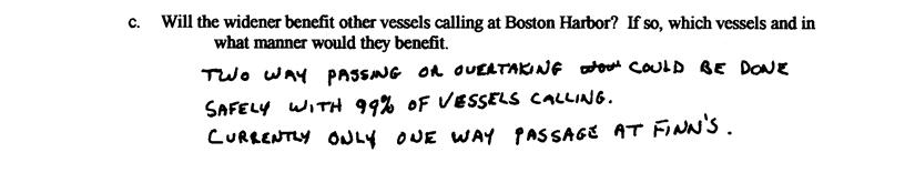
36 ERDC/CHL TR Recommendations Based upon the simulator results and the pilot s final questionnaires, the following recommendations are made for the Boston Harbor Channel improvements: a. The Boston North Channel bend widener is recommended without any modifications. b. The widening of the Main Ship Channel is recommended without any modifications. c. The Plan 1 turning notch is recommended with the modifications shown in Figure 14. A number of ships left the northeastern edge of the turning notch. This edge should be extended 100 ft. A number of ships also left the northeast end of the Reserved Channel. Modifying the Plan 1 notch to resemble the Plan 2 notch in this area is recommended. d. The Plan 2 turning notch is recommended without any modifications. Only two pilots were able to test the Plan 2 notch, and they felt the notch was adequate. It is recommended that two additional pilots participate in a 2- or 3-day simulation program to verify these results. The modified Plan 1 turning notch could also be simulated at this time. However, this is not a requirement.
37 ERDC/CHL TR Figure 14. Recommended modifications to the Plan 1 turning notch.
38 ERDC/CHL TR References Ankudinov, V Development of two hi-fidelity ship models for a ship simulation study of Boston Harbor: COSCO Hamburg, and Delaware Bridge. Arlington, VA: BTM Designers & Planners, Inc. Wilkelman, J., Z. Demirbilek, and L. Lin. Boston Harbor Deep Draft Navigation Channel Improvement: 2-D Hydraulic Modeling. In preparation.
39 ERDC/CHL TR
40 ERDC/CHL TR
41 ERDC/CHL TR
42 ERDC/CHL TR
43 ERDC/CHL TR
44 ERDC/CHL TR
45 ERDC/CHL TR
46 ERDC/CHL TR
47 ERDC/CHL TR
48 ERDC/CHL TR
49 ERDC/CHL TR
50 ERDC/CHL TR
51 ERDC/CHL TR
52 ERDC/CHL TR
53 ERDC/CHL TR
54 ERDC/CHL TR
55 ERDC/CHL TR
56 ERDC/CHL TR
57 ERDC/CHL TR
58 ERDC/CHL TR
59 ERDC/CHL TR
60 ERDC/CHL TR
61 ERDC/CHL TR
62 ERDC/CHL TR
63 ERDC/CHL TR
64 ERDC/CHL TR
65 ERDC/CHL TR
66 ERDC/CHL TR Appendix A: Pilot Questionnaires
67 ERDC/CHL TR
68 ERDC/CHL TR
69 ERDC/CHL TR
70 ERDC/CHL TR
71 ERDC/CHL TR
72 ERDC/CHL TR
73 ERDC/CHL TR
74 ERDC/CHL TR
75 ERDC/CHL TR
76 ERDC/CHL TR
77 ERDC/CHL TR
78 ERDC/CHL TR
79 ERDC/CHL TR
80 ERDC/CHL TR
81 ERDC/CHL TR

82 ERDC/CHL TR
83 ERDC/CHL TR

84 ERDC/CHL TR
85 ERDC/CHL TR
86 ERDC/CHL TR
87 ERDC/CHL TR

88 ERDC/CHL TR

89 ERDC/CHL TR
90 ERDC/CHL TR
91 ERDC/CHL TR
92 ERDC/CHL TR
93 ERDC/CHL TR
94 ERDC/CHL TR
95 ERDC/CHL TR
96 ERDC/CHL TR
97 ERDC/CHL TR
98 REPORT DOCUMENTATION PAGE Form Approved OMB No Public reporting burden for this collection of information is estimated to average 1 hour per response, including the time for reviewing instructions, searching existing data sources, gathering and maintaining the data needed, and completing and reviewing this collection of information. Send comments regarding this burden estimate or any other aspect of this collection of information, including suggestions for reducing this burden to Department of Defense, Washington Headquarters Services, Directorate for Information Operations and Reports ( ), 1215 Jefferson Davis Highway, Suite 1204, Arlington, VA Respondents should be aware that notwithstanding any other provision of law, no person shall be subject to any penalty for failing to comply with a collection of information if it does not display a currently valid OMB control number. PLEASE DO NOT RETURN YOUR FORM TO THE ABOVE ADDRESS. 1. REPORT DATE (DD-MM-YYYY) 3. DATES COVERED (From - To) August TITLE AND SUBTITLE 2. REPORT TYPE Final report Boston Harbor, Massachusetts, Deep-Draft Navigation Improvement Project Feasibility Study; Channel Improvement Investigations 5a. CONTRACT NUMBER 5b. GRANT NUMBER 5c. PROGRAM ELEMENT NUMBER 6. AUTHOR(S) Dennis W. Webb and Mark L. Habel 5d. PROJECT NUMBER 5e. TASK NUMBER 5f. WORK UNIT NUMBER 7. PERFORMING ORGANIZATION NAME(S) AND ADDRESS(ES) 8. PERFORMING ORGANIZATION REPORT NUMBER Coastal and Hydraulics Laboratory, U.S. Army Engineer Research and Development Center, 3909 Halls Ferry Road, Vicksburg, MS ; U.S. Army Engineer District, New England, 696 Virginia Road Concord, MA ERDC/CHL TR SPONSORING / MONITORING AGENCY NAME(S) AND ADDRESS(ES) 10. SPONSOR/MONITOR S ACRONYM(S) U.S. Army Engineer District, New England 696 Virginia Road Concord, MS SPONSOR/MONITOR S REPORT NUMBER(S) 12. DISTRIBUTION / AVAILABILITY STATEMENT Approved for public release; distribution is unlimited. 13. SUPPLEMENTARY NOTES 14. ABSTRACT Boston Harbor is located on the eastern shore of the Commonwealth of Massachusetts, on Massachusetts Bay. The Corps of Engineers and the Massachusetts Port Authority (Massport) are evaluating a number of improvements to Boston Harbor. These improvements include deepening and widening portions of the Broad Sound North Entrance Channel, Main Ship Channel, and lower Reserved Channel and its turning area for the benefit of larger container vessels calling on Massport s Conley Terminal. To assist in evaluating these improvements, the U.S. Army Engineer Research and Development Center (ERDC) conducted a ship-simulator-based navigation study. Data for the simulation models were obtained during a site visit to ride ships in the project area. Currents for both the existing and proposed channels were calculated using the ADCIRC computer model in a joint effort between ERDC and the U.S. Army Engineer District, New England. Harbor pilots traveled from Boston to validate and operate the simulations in September SUBJECT TERMS Boston Harbor simulation Navigation Reserved Channel 16. SECURITY CLASSIFICATION OF: 17. LIMITATION OF ABSTRACT a. REPORT Unclassified b. ABSTRACT Unclassified c. THIS PAGE Unclassified 18. NUMBER OF PAGES 98 19a. NAME OF RESPONSIBLE PERSON 19b. TELEPHONE NUMBER (include area code) Standard Form 298 (Rev. 8-98) Prescribed by ANSI Std
UNITED NEW YORK SANDY HOOK PILOTS BENEVOLENT ASSOCIATION AND UNITED NEW JERSEY SANDY HOOK PILOTS BENEVOLENT ASSOCIATION
 UNITED NEW YORK SANDY HOOK PILOTS BENEVOLENT ASSOCIATION AND UNITED NEW JERSEY SANDY HOOK PILOTS BENEVOLENT ASSOCIATION TO: All Shipping Agents and Interested Parties January 19, 2017 SUBJECT: Anchorage
MAC Transit Advisories as of April 30, 2018
 MAC Transit Advisories as of April 30, 2018 The Mariners Advisory Committee for the Bay and River Delaware was established in October 1964. Its members and associate members are mainly comprised of master
Delaware River Vessel Reporting System Mariners Advisory Committee For
 Delaware River Vessel Reporting System Mariners Advisory Committee For the Bay and River Delaware The Mariner's Advisory Committee is comprised of Master Mariners, River Pilots, and concerns itself with
Transport Infrastructure Act 1994 Gladstone Ports Corporation. Port Notice 04/17 LNG Vessel Operating Parameters
 Transport Infrastructure Act 1994 Gladstone Ports Corporation Port Notice 04/17 LNG Vessel Operating Parameters 1. These operating parameters have been developed based on navigation simulations with LNG
COAST GUARD ADVISORY NOTICE (CGAN ) To: Distribution Date: September 1, 2017
 To: Distribution Date: September 1, 2017") Commander United States Coast Guard Sector New York 212 Coast Guard Drive Staten Island, NY 10305 Staff Symbol: (spw) Phone: (718) 354-2353 Fax: (718) 354-4190 COAST GUARD ADVISORY NOTICE (CGAN 2017-016)
Commander United States Coast Guard Sector New York 212 Coast Guard Drive Staten Island, NY 10305 Staff Symbol: (spw) Phone: (718) 354-2353 Fax: (718) 354-4190 COAST GUARD ADVISORY NOTICE (CGAN 2017-016)
Examples of Carter Corrected DBDB-V Applied to Acoustic Propagation Modeling
 Naval Research Laboratory Stennis Space Center, MS 39529-5004 NRL/MR/7182--08-9100 Examples of Carter Corrected DBDB-V Applied to Acoustic Propagation Modeling J. Paquin Fabre Acoustic Simulation, Measurements,
M2.50-cal. Multishot Capabilities at the US Army Research Laboratory
 ARL-TN-0694 SEP 2015 US Army Research Laboratory M2.50-cal. Multishot Capabilities at the US Army Research Laboratory by Todd Brinkman Approved for public release; distribution is unlimited. NOTICES Disclaimers
SHIP NAVIGATION SIMULATION STUDY MIAMI HARBOR NAVIGATION IMPROVEMENT PROJECT, MIAMI, FLORIDA. For Public Release; Distribution Unlimited
 91 4 3 5 AD-A2 4 569TECHNICAL REPORT HL-91-6 SHIP NAVIGATION SIMULATION STUDY MIAMI HARBOR NAVIGATION IMPROVEMENT PROJECT, MIAMI, FLORIDA by J. Christopher Hewlett \ Hydraulics Laboratory -L-._.. \ \ DEPARTMENT
GENERAL LIMITATIONS AND RESTRICTIONS. LNGC Temporary Exemption (Effective August 21, 2018)
") RULES AND REGULATIONS GOVERNING PILOTS AND PILOTAGE ON THE CORPUS CHRISTI SHIP CHANNEL EFFECTIVE AUGUST 1, 2013 AMENDED EFFECTIVE MAY 13, 2014 AMENDED EFFECTIVE OCTOBER 1, 2014 AMENDED EFFECTIVE JANUARY
RULES AND REGULATIONS GOVERNING PILOTS AND PILOTAGE ON THE CORPUS CHRISTI SHIP CHANNEL EFFECTIVE AUGUST 1, 2013 AMENDED EFFECTIVE MAY 13, 2014 AMENDED EFFECTIVE OCTOBER 1, 2014 AMENDED EFFECTIVE JANUARY
Characterizing The Surf Zone With Ambient Noise Measurements
 Characterizing The Surf Zone With Ambient Noise Measurements LONG-TERM GOAL Grant Deane Marine Physical Laboratory Scripps Institution of Oceanography La Jolla, CA 93093-0213 phone: (619) 534-0536 fax:
z Interim Report for May 2004 to October 2005 Aircrew Performance and Protection Branch Wright-Patterson AFB, OH AFRL-HE-WP-TP
 AFRL-HE-WP-TP-26-89 Neck Muscle Fatigue with Helmet-Mounted Systems Edward S. Eveland Joseph A. Pellettiere Air Force Research Laboratory LL September 26 z Interim Report for May 24 to October 25 (n 261124
Ship Navigation Simulation Study, Port Jersey Channel, Bayonne, New Jersey
 Technical Report HL-96-19 September 1996 US Army Corps of Engineers Waterways Experiment Station Ship Navigation Simulation Study, Port Jersey Channel, Bayonne, New Jersey Volume I: Main Text by Michelle
GENERAL GUIDELINES FOR VESSELS TRANSITING RESTRICTED WATERWAYS OR PORTS
 GENERAL GUIDELINES FOR VESSELS TRANSITING RESTRICTED WATERWAYS OR PORTS Revised: March 5, 2018 TABLE OF CONTENTS GENERAL DEFINITIONS... 2 VESSEL SPACING... 3 HORIZONTAL CLEARANCE... 3 UNDER-KEEL CLEARANCE
World Shipping Council. Bureau of Ocean Energy Management U.S. Department of the Interior
 Comments of the World Shipping Council Submitted to the Bureau of Ocean Energy Management U.S. Department of the Interior In the matters of Commercial Leasing for Wind Power Development on the Outer Continental
DEVELOPMENT OF PRIMARY FRAGMENTATION SEPARATION DISTANCES FOR CASED CYLINDRICAL MUNITIONS
 DEVELOPMENT OF PRIMARY FRAGMENTATION SEPARATION DISTANCES FOR CASED CYLINDRICAL MUNITIONS by William H. Zehrt, Jr., P. E. and Michelle M. Crull, PhD, P. E. U. S. Army Engineering and Support Center, Huntsville
BRRAKING WAVE FORCES ON WALLS
 CETN-III-38 3/88 BRRAKING WAVE FORCES ON WALLS PURPOSE: To introduce the Goda method as an alternative to the Minikin method for the determination of breaking wave forces on semirigid wall structures.
Internal Waves and Mixing in the Aegean Sea
 Internal Waves and Mixing in the Aegean Sea Michael C. Gregg Applied Physics Laboratory, University of Washington 1013 NE 40 th St. Seattle, WA 98105-6698 phone: (206) 543-1353 fax: (206) 543-6785 email:
Marine Mammal Acoustic Tracking from Adapting HARP Technologies
 DISTRIBUTION STATEMENT A: Approved for public release; distribution is unlimited. Marine Mammal Acoustic Tracking from Adapting HARP Technologies Sean M. Wiggins and John A. Hildebrand Marine Physical
GENERAL LIMITATIONS AND RESTRICTIONS. Draft Restrictions
 RULES AND REGULATIONS GOVERNING PILOTS AND PILOTAGE ON THE CORPUS CHRISTI SHIP CHANNEL EFFECTIVE AUGUST 1, 2013 AMENDED EFFECTIVE MAY 13, 2014 AMENDED EFFECTIVE OCTOBER 1, 2014 I GENERAL The Rules and
( max)o Wind Waves 10 Short Swell (large wave steepness) 25 Long Swell (small wave steepness) 75
o Wind Waves 10 Short Swell (large wave steepness) 25 Long Swell (small wave steepness) 75") CEPi-I-18 REvKn, 3188 IRREGULAR WAVE DIFFRACTION BY GODA'S KETHOD PURPOSE : To provide a simplified method for determining random wave diffraction coefficients for a semi-infinite breakwater. GENERAL :
CEPi-I-18 REvKn, 3188 IRREGULAR WAVE DIFFRACTION BY GODA'S KETHOD PURPOSE : To provide a simplified method for determining random wave diffraction coefficients for a semi-infinite breakwater. GENERAL :
Kelly Legault, Ph.D., P.E. USACE SAJ
 Kelly Legault, Ph.D., P.E. USACE SAJ Report Documentation Page Form Approved OMB No. 0704-0188 Public reporting burden for the collection of information is estimated to average 1 hour per response, including
AFRL-RH-WP-TR
 AFRL-RH-WP-TR-2016-0040 C-130J BREATHING RESISTANCE STUDY George W. Miller Air Force Research Laboratory Wright-Patterson Air Force Base, OH 45433 May 2016 Final Report STINFO COPY AIR FORCE RESEARCH LABORATORY
DoD Coral Reef Protection and Management Program
 DoD Coral Reef Protection and Management Program PROJECT TEAM U.S. NAVY TOM EGELAND (ASN(I&E)) LORRI SCHWARTZ (NAVFAC) ALEX VIANA (NFESC) STEVE SMITH (NFESC) BOSTON UNIV. MARINE PRG. PHILLIP LOBEL MINDY
WORK-REST REQUIREMENTS FOR PILOTS
 AN ORDER OF THE BOARD OF PILOT COMMISSIONERS FOR THE PORT OF CORPUS CHRISTI AUTHORITY REGARDING WORK-REST REQUIREMENTS FOR PILOTS AND COMBINED BEAM RESTRICTION Whereas, the current Rules and Regulations
DRAFT. October 17, 2014 File No Mr. Brendhan Zubricki Town Administrator Essex Town Hall 30 Martin Street Essex, MA.
 GZA GeoEnvironmental, Inc. Engineers and Scientists October 17, 2014 File No. 18.0171857.00 Mr. Brendhan Zubricki Town Administrator Essex Town Hall 30 Martin Street Essex, MA. 01929 DRAFT Re: Essex River
Global Ocean Internal Wave Database
 Global Ocean Internal Wave Database Victor Klemas Graduate College of Marine Studies University of Delaware Newark, DE 19716 phone: (302) 831-8256 fax: (302) 831-6838 email: klemas@udel.edu Quanan Zheng
C C S Technical Information
 C C S Technical Information (2014) Technical Information No.7 Total No.129 Jan.28,2014 (Total 3+5+1 pages) To: CCS Surveyors, Plan Approval Surveyors, Relevant Ship Companies, Shipyards and Design Institutes
Temporary Flying Restrictions Due to Exogenous Factors
 Army Regulation 40 8 Medical Services Temporary Flying Restrictions Due to Exogenous Factors Headquarters Department of the Army Washington, DC 17 August 1976 UNCLASSIFIED REPORT DOCUMENTATION PAGE Form
The LA/LB Harbors handle more than 5,500 commercial vessel arrivals per year (excluding local coastwise and Catalina Island traffic).
.") X. SMALL CRAFT For the purpose of the Los Angeles and Long Beach Harbor Safety Plan, pleasure vessels, commercial fishing vessels and sportfishing boats are designated as small craft. A. BACKGROUND: The
X. SMALL CRAFT For the purpose of the Los Angeles and Long Beach Harbor Safety Plan, pleasure vessels, commercial fishing vessels and sportfishing boats are designated as small craft. A. BACKGROUND: The
Passage Key Inlet, Florida; CMS Modeling and Borrow Site Impact Analysis
 Passage Key Inlet, Florida; CMS Modeling and Borrow Site Impact Analysis by Kelly R. Legault and Sirisha Rayaprolu PURPOSE: This Coastal and Hydraulics Engineering Technical Note (CHETN) describes the
Comparisons of Physical and Numerical Model Wave Predictions with Prototype Data at Morro Bay Harbor Entrance, California
 Comparisons of Physical and Numerical Model Wave Predictions with Prototype Data at Morro Bay Harbor Entrance, California by Robert R. Bottin, Jr. and Edward F. Thompson PURPOSE: This Coastal and Hydraulics
PILOTAGE DIRECTIONS REVIEWED DECEMBER 2016
 PILOTAGE DIRECTIONS REVIEWED DECEMBER 2016 REVISION LIST Revision No. Date Details Approved by: Original All sections 12 Dec 2013 First edition of C W Brand v1.0 Pilotage Directions Revision 2 all sections
Pilotage Directions 2017
 Pilotage Directions 2017 1. Commencement These Pilotage Directions shall come into force on 31 st August 2017 on which date the existing Pilotage Directions are revoked. 2. Short Title These Pilotage Directions
APPROACH DEPTH(m) From East 15.0 From West From East 15.0 From West From East 15.0 From West ) ) From East 15.0 ) From West 16.
 From East 15.0 From West From East 15.0 From West From East 15.0 From West ) ) From East 15.0 ) From West 16.") UNIVERSAL TERMINAL (OMU) JETTY DEPTH A/S (m) APPROACH DEPTH(m) MAX LOA (m) MAX DISPL. (tonnes) REMARKS OMU1 23.0 From East 15.0 From West 22.5 346 384,604 VLCC berth OMU2 23.0 From East 15.0 From West
UNIVERSAL TERMINAL (OMU) JETTY DEPTH A/S (m) APPROACH DEPTH(m) MAX LOA (m) MAX DISPL. (tonnes) REMARKS OMU1 23.0 From East 15.0 From West 22.5 346 384,604 VLCC berth OMU2 23.0 From East 15.0 From West
High-Frequency Scattering from the Sea Surface and Multiple Scattering from Bubbles
 High-Frequency Scattering from the Sea Surface and Multiple Scattering from Bubbles Peter H. Dahl Applied Physics Laboratory College of Ocean and Fisheries Sciences University of Washington Seattle, Washington
Using SolidWorks & CFD to Create The Next Generation Airlocks
 Using SolidWorks & CFD to Create The Next Generation Airlocks Matthew Gaffney Mechanical Engineer Geo-Centers, INC US Army Natick Soldier Center Natick, MA 01760 508-233-5557 Matthew.gaffney@natick.army.mil
AN EXPERIMENTAL INVESTIGATION OF SPILLING BREAKERS
 AN EXPERIMENTAL INVESTIGATION OF SPILLING BREAKERS Prof. James H. Duncan Department of Mechanical Engineering University of Maryland College Park, Maryland 20742-3035 phone: (301) 405-5260, fax: (301)
Navy Shipbuilding Industrial Base
 Navy Shipbuilding Industrial Base May 11, 2011 David J. Berteau Senior Adviser and Director, Defense-Industrial Initiatives Report Documentation Page Form Approved OMB No. 0704-0188 Public reporting burden
U. S. Coast Guard Sector Boston Merrimack River Approach and Entrance, MA. Waterways Management Survey
 U. S. Coast Guard Sector Boston Merrimack River Approach and Entrance, MA. Waterways Management Survey The Waterways Analysis and Management Survey (WAMS) process is an essential component of both the
AFRL-RX-WP-TP
 AFRL-RX-WP-TP-2012-0215 REVERSE PRESSURE CAPABLE FINGER SEAL (PREPRINT) Nathan Gibson and Joe Yanof Honeywell International, Inc. JANUARY 2012. See additional restrictions described on inside pages STINFO
Coastal Harbors and Waterways, NC (Shallow Draft Navigation) (O&M)
 (O&M)") Coastal Harbors and Waterways, NC (Shallow Draft Navigation) (O&M) Shallow draft coastal harbors include a subsistence harbor at Silver Lake CONGRESSIONAL DISTRICT: NC 3, 7 DATE: 23 April 2018 1. AUTHORIZATION:
Coastal Harbors and Waterways, NC (Shallow Draft Navigation) (O&M) Shallow draft coastal harbors include a subsistence harbor at Silver Lake CONGRESSIONAL DISTRICT: NC 3, 7 DATE: 23 April 2018 1. AUTHORIZATION:
Forth Ports Limited. Port of Dundee. Rig Move Guidelines
 Forth Ports Limited Port of Dundee Contents 1 Introduction... 4 2 Pre-Arrival... 4 2.1 Planning Meetings... 4 2.2 Priority of Movements... 4 2.3 Confirmation/Cancellations... 5 2.4 Weather Parameters...
Towed Barge Standard of Care
 Lower Columbia Region Harbor Safety Committee Towed Barge Standard of Care Page 1 of 6 A. 1. Purpose The Columbia River is intended to eliminate conflicts between towing vessels conducting astern towing
Assessment Simulation study, Phase 2. Port of Roenne. FORCE / Rev. B
 / Rev. B i LIST OF CONTENTS: PAGE: 0. EXECUTIVE SUMMARY... 1 1. INTRODUCTION... 2 1.1. General... 2 1.2. Objectives... 3 2. SUMMARY... 4 2.1. Observations... 5 2.2.1 General... 5 2.2.2 Weather conditions...
COOPERATIVE VESSEL TRAFFIC SERVICE (CVTS) TAMPA BAY, FLORIDA
 TAMPA BAY, FLORIDA") COOPERATIVE VESSEL TRAFFIC SERVICE (CVTS) TAMPA BAY, FLORIDA USERS MANUAL Oct 2010 1 st Edition Serving the Port of Tampa, Port Manatee, Port of Saint Petersburg, and the Waterways of Tampa Bay 1 Table
COOPERATIVE VESSEL TRAFFIC SERVICE (CVTS) TAMPA BAY, FLORIDA USERS MANUAL Oct 2010 1 st Edition Serving the Port of Tampa, Port Manatee, Port of Saint Petersburg, and the Waterways of Tampa Bay 1 Table
Wexford Harbour. Yachting Guide. Navigation
 Wexford Harbour Yachting Guide Navigation This document supersedes all previous editions. Approvals: Yacht Club Committee April, 2015 Wexford Board of Directors April, 2015 # Date Section Revision 1 6.5.2015
Columbia River Pilots Vessel Movement Guidelines. Table of Contents
 Columbia River Pilots Vessel Movement Guidelines Table of Contents I. Introduction.... 2 II. Pilot Transfers.. 3 III. General Information.... 4 Harbor Safety Plan... 4 Restricted Main Engine RPMs 4 Channel
Use of AIS and AISAP for Analysis of Vessel Wakes in Charleston Harbor: A Case Study
 Use of AIS and AISAP for Analysis of Vessel Wakes in Charleston Harbor: A Case Study by Brandan Scully and Anne McCartney PURPOSE: This Coastal and Hydraulics Engineering Technical Note (CHETN) describes
Movement and traffic procedures
 Section 3 Movement and traffic procedures Maritime Safety Queensland, through the authority of the Regional Harbour Master, has jurisdiction over the safe movement of all shipping within the pilotage area.
Marine Safety Information Bulletin COAST GUARD GUIDANCE FOR DEAD SHIP MOVEMENT IN SECTOR HONOLULU CAPTAIN OF THE PORT ZONE.
 Marine Safety Information Bulletin 16-002 U.S. DEPARTMENT OF HOMELAND SECURITY U. S. Coast Guard Sector Honolulu Sand Island Parkway Honolulu, Hawaii 96819 (808) 842-2600 COAST GUARD GUIDANCE FOR DEAD
Channel Turns. Cape Fear River
 A Look at the Channel Turns in the Cape Fear River Revised November 5, 2011 Prepared for Save the Cape, Inc. Southport, North Carolina Contents The Channel in the Cape Fear River...2 Experience...7 Corps
National Maritime Center
 National Maritime Center Providing Credentials to Mariners (Sample Examination) Page 1 of 8 Choose the best answer to the following Multiple Choice Questions. 1. Assume that your vessel has just entered
HELSINKI COMMISSION HELCOM SAFE NAV 4/2014 Group of Experts on Safety of Navigation Fourth Meeting Helsinki, Finland, 4 February 2014
 HELSINKI COMMISSION HELCOM SAFE NAV 4/2014 Group of Experts on Safety of Navigation Fourth Meeting Helsinki, Finland, 4 February 2014 Agenda Item 3 Accidents and ship traffic in the Baltic Sea Document
ROYAL VANCOUVER YACHT CLUB
 ROYAL VANCOUVER YACHT CLUB PROPOSED EXPANSION PROJECT NAVIGATION CHANNEL DESIGN COAL HARBOUR Prepared for: Royal Vancouver Yacht Club Prepared by: Typlan Consulting Ltd. March 2016 Page 1 of 17 March 23,
Implementation of Structures in the CMS: Part IV, Tide Gate
 Implementation of Structures in the CMS: Part IV, Tide Gate by Honghai Li, Alejandro Sanchez, and Weiming Wu PURPOSE: This Coastal and Hydraulics Engineering Technical Note (CHETN) describes the mathematical
Remote Monitoring of Dolphins and Whales in the High Naval Activity Areas in Hawaiian Waters
 DISTRIBUTION STATEMENT A: Approved for public release; distribution is unlimited. Remote Monitoring of Dolphins and Whales in the High Naval Activity Areas in Hawaiian Waters Whitlow W. L. Au and Marc
Coastal Harbors and Waterways, NC (Shallow Draft Navigation) (O&M)
 (O&M)") Coastal Harbors and Waterways, NC (Shallow Draft Navigation) (O&M) Shallow draft coastal harbors include a subsistence harbor at Silver Lake CONGRESSIONAL DISTRICT: NC 3 and 7 DATE: 23 February 2015 1.
Coastal Harbors and Waterways, NC (Shallow Draft Navigation) (O&M) Shallow draft coastal harbors include a subsistence harbor at Silver Lake CONGRESSIONAL DISTRICT: NC 3 and 7 DATE: 23 February 2015 1.
This direction contains the requirements for the compulsory pilotage areas within the Auckland region. This
 Harbourmaster s Direction 2-15 Pilotage Foreword This direction contains the requirements for the compulsory pilotage areas within the Auckland region. This direction updates and supersedes previous Harbourmaster
CORPS FACTS. Harbor Dredging U.S. ARMY CORPS OF ENGINEERS BUILDING STRONG
 CORPS FACTS Harbor Dredging U.S. ARMY CORPS OF ENGINEERS BUILDING STRONG Disaster Response Sedimentation in the channel is caused by the normal cycle of silt movement, erosion from high water or heavy
World Shipping Council. National Oceanographic and Atmospheric Administration
 Comments of the World Shipping Council Submitted to the National Oceanographic and Atmospheric Administration In the matter of Endangered and Threatened Species; Petition for Rulemaking to Establish a
BookletChart. Sand Key to Rebecca Shoal NOAA Chart A reduced-scale NOAA nautical chart for small boaters
 BookletChart Sand Key to Rebecca Shoal NOAA Chart 11439 A reduced-scale NOAA nautical chart for small boaters When possible, use the full-size NOAA chart for navigation. Published by the National Oceanic
(Refer Slide Time: 00:32)
") Port and Harbour Structures By Prof R. Sundaravadivelu Department of Ocean Engineering, Indian Institute of Technology Madras Module 8, Lecture 43 Detailed Project Report So last class we discussed about
Port and Harbour Structures By Prof R. Sundaravadivelu Department of Ocean Engineering, Indian Institute of Technology Madras Module 8, Lecture 43 Detailed Project Report So last class we discussed about
State of Texas Operations and Maintenance
 State of Texas Operations and Maintenance Barbour Terminal Ship Channel The Barbour Terminal Channel and Turning Basin is a 1.7-mile-long deep draft waterway that extends from the Houston Ship Channel
Preventing Damage to Harbour Facilities and. Ship Handling in Harbours PART 2 INDEX
 Preventing Damage to Harbour Facilities and Ship Handling in Harbours PART 2 INDEX 1 Vessel handling is based on the basic knowledge that a vessel floats in the water and returns to its original position
Gorgon - Pilotage - Passage Plan Materials Offloading Facility (MOF) to PBG
 to PBG") Gorgon - Pilotage - Passage Plan Materials Offloading Facility (MOF) to PBG 1.0 Introduction Vessels transiting within port limits from the Materials Offloading Facility (MOF) to the Barrow Island Pilot
Gorgon - Pilotage - Passage Plan Materials Offloading Facility (MOF) to PBG 1.0 Introduction Vessels transiting within port limits from the Materials Offloading Facility (MOF) to the Barrow Island Pilot
BookletChart. Intracoastal Waterway Matecumbe to Grassy Key NOAA Chart A reduced-scale NOAA nautical chart for small boaters
 BookletChart Intracoastal Waterway Matecumbe to Grassy Key NOAA Chart 11449 A reduced-scale NOAA nautical chart for small boaters When possible, use the full-size NOAA chart for navigation. Published by
V. HARBOR DEPTHS, CHANNEL DESIGN AND PROPOSED CONSTRUCTION AND DREDGING
 V. HARBOR DEPTHS, CHANNEL DESIGN AND PROPOSED CONSTRUCTION AND DREDGING A. DISCUSSION: For the most part, projects that involve dredging and construction require a comprehensive design and review process
Waves, Bubbles, Noise, and Underwater Communications
 Waves, Bubbles, Noise, and Underwater Communications Grant B. Deane Marine Physical Laboratory, Scripps Institution of Oceanography UCSD, La Jolla, CA 92093-0238 phone: (858) 534-0536 fax: (858) 534-7641
Three Dimensional Shallow Water Adaptive Hydraulics (ADH-SW3): Waterborne Vessels
: Waterborne Vessels") Three Dimensional Shallow Water Adaptive Hydraulics (ADH-SW3): Waterborne Vessels by Gaurav Savant and Corey J. Trahan PURPOSE: This Coastal and Hydraulics Engineering Technical Note (CHETN) describes
Three Dimensional Shallow Water Adaptive Hydraulics (ADH-SW3): Waterborne Vessels by Gaurav Savant and Corey J. Trahan PURPOSE: This Coastal and Hydraulics Engineering Technical Note (CHETN) describes
Long-Term Autonomous Measurement of Ocean Dissipation with EPS-MAPPER
 Long-Term Autonomous Measurement of Ocean Dissipation with EPS-MAPPER Neil S. Oakey Bedford Institute of Oceanography Dartmouth, Nova Scotia Canada B2Y 4A2 phone: (902) 426-3147 fax: (902) 426-7827 e-mail:
APPENDIX D REAL ESTATE PLAN
 NAVIGATION IMPROVEMENTS SITKA HARBOR, ALASKA CHANNEL ROCK BREAKWATERS DRAFT DEFICIENCY CORRECTION EVALUATION REPORT APPENDIX D REAL ESTATE PLAN JANUARY 2011 REAL ESTATE PLAN FOR SITKA HARBOR, ALASKA CHANNEL
BookletChart. Chesapeake Bay Severn and Magothy Rivers NOAA Chart A reduced-scale NOAA nautical chart for small boaters
 BookletChart Chesapeake Bay Severn and Magothy Rivers NOAA Chart 12282 A reduced-scale NOAA nautical chart for small boaters When possible, use the full-size NOAA chart for navigation. Published by the
Port Sections Guide Section 01
 s Guide 01 Cow Bay Marina Date 10/1/2016 Position (lat / lon) Minimum controlled water depth Chart datum Range of water densities Tidal range alongside Bottom type Dredging regime Distance pilot station
ADANI PORTS & SEZ LTD. ++ MUNDRA PORT ++ GENERAL INFORMATION
 ADANI PORTS & SEZ LTD. ++ MUNDRA PORT ++ GENERAL INFORMATION LOCATION Mundra Port is all weather, independent, commercial port with geographical and hydrological advantages on the West Coast of India,
applied to Port Development and Inland Waterway Transport
 applied to Port Development and Inland Waterway Transport Wytze de Boer March 12, 2018 w.d.boer@marin.nl CHALLINGING WIND AND WAVES applied to port development and inland waterway transport AGENDA 1. Introduction
Enclosure (5) to NVIC 03-16
 to NVIC 03-16") TOWING OFFICER ASSESSMENT RECORD LIMITED LOCAL AREA LOCAL LIMITED AREA (LLA) TOAR INSTRUCTIONS FOR USE The following Towing Officer Assessment Record (TOAR) is intended as a model for endorsements as Limited
TOWING OFFICER ASSESSMENT RECORD LIMITED LOCAL AREA LOCAL LIMITED AREA (LLA) TOAR INSTRUCTIONS FOR USE The following Towing Officer Assessment Record (TOAR) is intended as a model for endorsements as Limited
TITLE: Assessing the Hydrodynamic Performance of Fouling-Release Surfaces (ONR Research Contract # N WR )
") TITLE: Assessing the Hydrodynamic Performance of Fouling-Release Surfaces (ONR Research Contract # N00014-07-WR-2-0213) INVESTIGATOR: Associate Professor Michael P. Schultz, Naval Architecture & Ocean
TITLE: Assessing the Hydrodynamic Performance of Fouling-Release Surfaces (ONR Research Contract # N00014-07-WR-2-0213) INVESTIGATOR: Associate Professor Michael P. Schultz, Naval Architecture & Ocean
Port of Corpus Christi
 Port of Corpus Christi Pilot Board Meeting Tuesday, May 13, 2014 8:00 AM Port of Corpus Christi Pilot Board Meeting Tuesday, May 13, 2014-8:00 AM Congressman Solomon P. Ortiz International Center located
PILOTAGE INFORMATION
 PILOTAGE INFORMATION Revised A PILOTAGE DIRECTIONS The Gloucester Harbour Trustees is the Competent Harbour Authority for the Gloucester Harbour under the Pilotage Act 1987 and responsible for the provision
LOCAL NOTICE TO MARINERS
 USCG Notice to Mariners 3/7/18 (View full Notice here) LNM 10/18 Coast Guard District 1: U.S. Department of Homeland Security United States Coast Guard LOCAL NOTICE TO MARINERS COASTAL WATERS FROM EASTPORT,
Forth Ports Limited. Ruling Depths & Under Keel Clearances
 Forth Ports Limited - Forth Vessels are scheduled into / out of ports on the Forth & Tay in accordance with the under keel clearance criteria specified in this section of the Marine Guidelines & Port Information.
AUTORIDAD DEL CANAL DE PANAMÁ EXECUTIVE VICE PRESIDENCY FOR OPERATIONS
 3654-A (OPXI v. 3-2-2011 AUTORIDAD DEL CANAL DE PANAMÁ EXECUTIVE VICE PRESIDENCY FOR OPERATIONS ADVISORY TO SHIPPING No. A-20-2013 August 2, 2013 TO : All Shipping Agents, Owners, and Operators SUBJECT:
Development of Low Volume Shape Memory Alloy Variable Ballast System for AUV Use
 Development of Low Volume Shape Memory Alloy Variable Ballast System for AUV Use Dr. Graeme J Rae Ocean Engineering Program Division of Marine and Environmental Systems Florida Institute of Technology
Tedious Creek Small Craft Harbor: CGWAVE Model Comparisons Between Existing and Authorized Breakwater Configurations
 Tedious Creek Small Craft Harbor: CGWAVE Model Comparisons Between Existing and Authorized Breakwater Configurations by Michael J. Briggs, Barbara P. Donnell, Zeki Demirbilek, and Robert D. Carver PURPOSE:
THE SYLLABUS FOR WRITTEN EXAMINATION PILOT'S FOURTH CLASS LICENCE (TEES AND HARTLEPOOL) AND
 AND") PD TEESPORT CONSERVANCY DIVISION HARBOUR MASTER'S OFFICE THE SYLLABUS FOR WRITTEN EXAMINATION IN RESPECT OF A PILOT'S FOURTH CLASS LICENCE (TEES AND HARTLEPOOL) AND PILOTAGE EXEMPTION CERTIFICATE (Issued
PD TEESPORT CONSERVANCY DIVISION HARBOUR MASTER'S OFFICE THE SYLLABUS FOR WRITTEN EXAMINATION IN RESPECT OF A PILOT'S FOURTH CLASS LICENCE (TEES AND HARTLEPOOL) AND PILOTAGE EXEMPTION CERTIFICATE (Issued
Cruise Report Marine Mammal and Sea Turtle Observer UNDET Monitoring Hawaii Range Complex: 3 April 2014
 January 15, 2015 Cruise Report Marine Mammal and Sea Turtle Observer UNDET Monitoring Hawaii Range Complex: 3 April 2014 Prepared for: Commander, U.S. Pacific Fleet Prepared by: Naval Facilities Engineering
World Shipping Council. Bureau of Ocean Energy Management Department of the Interior
 Comments of the World Shipping Council Submitted to the Bureau of Ocean Energy Management Department of the Interior In the matter of Commercial Leasing for Wind Power Development on the Outer Continental
PORT INFO GENERAL BERTH INFO
 s ervices SHIPWRIGHT WWW.SHIPWRIGHTSERVICES.CO.ZA 9 DE DUINE CLOSE, BLUEWATERBAY, SALDANHA, 7395, WESTERN CAPE, SOUTH AFRICA TEL. +27 71 040 6022 EMAIL. DERICK@SHIPWRIGHTSERVICES.CO.ZA PORT INFO GENERAL
FOR INFORMATION ONLY
 An investigation into the feasibility of piloting large cruise ships to and from a proposed terminal within the Gold Coast Broadwater Part A Simulation Plan Captain John Watkinson Meridian Maritime Services
HOUSTON SEA CHEST CLOGGING SURVEY
 HOUSTON SEA CHEST CLOGGING SURVEY *** YOUR HELP IS VOLUNTARY AND ANONYMOUS*** ***PLEASE DO NOT INCLUDE VESSEL NAME OR NUMBER *** IT IS 2015 MENHADEN SEASON IN THE HOUSTON SHIP CHANNEL To Vessel Master/Chief
Coastal Harbors and Waterways, NC (Shallow Draft Navigation) (O&M)
 (O&M)") Coastal Harbors and Waterways, NC (Shallow Draft Navigation) (O&M) Shallow draft coastal harbors include a subsistence harbor at Silver Lake CONGRESSIONAL DISTRICT: NC 3 and 7 DATE: 23 February 2015 1.
Coastal Harbors and Waterways, NC (Shallow Draft Navigation) (O&M) Shallow draft coastal harbors include a subsistence harbor at Silver Lake CONGRESSIONAL DISTRICT: NC 3 and 7 DATE: 23 February 2015 1.
2005 ABC. Chapter 3 Part 2. Navigating with ATON's. Revision to D-13 Local Notes. Instructor Notes for Mike Brough. Mike Brough
 2005 ABC Chapter 3 Part 2 Navigating with ATON's Revision to D-13 Local Notes Instructor Notes for Mike Brough Mike Brough June 24 2008 June 24 2008 Slide 1 June 24 2008 New graphics Navigating on Water
Comparison of Predicted and Measured Shoaling at Morro Bay Harbor Entrance, California
 Comparison of Predicted and Measured Shoaling at Morro Bay Harbor Entrance, California by Edward F. Thompson, Inocencio P. DiRamos, and Robert R. Bottin, Jr. PURPOSE: This Coastal and Hydraulics Engineering
Rules Practice Exam 11
 1 BOTH INTERNATIONAL & INLAND While underway in fog, you hear a vessel sound one prolonged blast followed by two short blasts on the whistle. What does this signal indicate? A. A vessel towing B. A vessel
Appendix 12: Marine Transportation Study. (Gartner Lee Ltd. 2008)
") Appendix 12: Marine Transportation Study (Gartner Lee Ltd. 2008) memorandum to: John Woods, Minas Basin Pulp and Power Co. Ltd from: Joseph Kozak date: ref: GLL 80308 re: FINAL Technical Marine Transportation
Appendix 12: Marine Transportation Study (Gartner Lee Ltd. 2008) memorandum to: John Woods, Minas Basin Pulp and Power Co. Ltd from: Joseph Kozak date: ref: GLL 80308 re: FINAL Technical Marine Transportation
1-32 NOME HARBOR, ALASKA (CWIS NOS , 87755, 12270, & 10422) Condition of Improvement 30 September 2012
 Condition of Improvement 30 September 2012") NOME HARBOR 1-32 NOME HARBOR, ALASKA (CWIS NOS. 72742, 87755, 12270, & 10422) Condition of Improvement 30 September 2012 AUTHORIZATION: (1) Rivers and Harbors Act, 8 August 1917 (House Doc. 1932, 64th
NOME HARBOR 1-32 NOME HARBOR, ALASKA (CWIS NOS. 72742, 87755, 12270, & 10422) Condition of Improvement 30 September 2012 AUTHORIZATION: (1) Rivers and Harbors Act, 8 August 1917 (House Doc. 1932, 64th
Uncontrolled document if printed.
 APPENDIX 3 APPRENTICE PILOT S TRAINING SYLLABUS Issue Date: 16 th March, 2010 Date of Revision: 22nd May, 2013 Revision #2 i THE PURPOSE OF THIS SYLLABUS The purpose of this training syllabus is to ensure
MOREHEAD CITY HARBOR, NC. Dredged Material Management Plan (DMMP)
") MOREHEAD CITY HARBOR, NC Dredged Material Management Plan (DMMP) Public Meeting/Info Session 15 January 2014 US Army Corps of Engineers Morehead City Harbor DMMP Presentation Topics Morehead City Harbor
MOREHEAD CITY HARBOR, NC Dredged Material Management Plan (DMMP) Public Meeting/Info Session 15 January 2014 US Army Corps of Engineers Morehead City Harbor DMMP Presentation Topics Morehead City Harbor
Accommodating Larger Vessels: Ship Maneuverability and Channel Depth; A discussion of vessel motion in shallow water and future research needs.
 Accommodating Larger Vessels: Ship Maneuverability and Channel Depth; A discussion of vessel motion in shallow water and future research needs. PANELISTS: Paul Amos: President, Columbia River Pilots. Larry
DEPARTMENT OF THE ARMY GALVESTON DISTRICT, CORPS OF ENGINEERS P.O. BOX 1229 GALVESTON, TEXAS CESWG-CDR (1145)
") DEPARTMENT OF THE ARMY GALVESTON DISTRICT, CORPS OF ENGINEERS P.O. BOX 1229 GALVESTON, TEXAS 77553-1229 REPLY TO ATTENTION OF CESWG-CDR (1145) TBD MEMORANDUM FOR All Galveston District Personnel. SUBJECT:
DEPARTMENT OF THE ARMY GALVESTON DISTRICT, CORPS OF ENGINEERS P.O. BOX 1229 GALVESTON, TEXAS 77553-1229 REPLY TO ATTENTION OF CESWG-CDR (1145) TBD MEMORANDUM FOR All Galveston District Personnel. SUBJECT: