THE DESIGN OF WING SECTIONS
|
|
|
- Suzanna Ryan
- 6 years ago
- Views:
Transcription
1 THE DESIGN OF WING SECTIONS Published in "Radio Control Model News" Issue Number 8 Winter 93 Aerofoil section design has advanced a great deal since great pioneers like Horatio Phillips experimented with wind tunnels. Phillips invented the double surfaced, cambered wing section in 1884 when most other people at his time had been working with single thicknesses of fabric stretched over light frames. Having found that a pointed leading edge tended to cause flow separation on the under side of his sections, Phillips introduced a carefully shaped bulge on the under side which guided the flow round this critical area. He called this the Phillips Entry. It was patented in It is astonishing that some model fliers still talk about the Phillips Entry, not realising that they are a full century out of date! Moreover, the original Phillips Entry was quite different from the feature that is usually intended now. It is time the term 'Phillips Entry' made its final exit! One of the important things that has been proved since Phillips' time, is that we cannot treat the airflow over and under a wing as entirely separate. In a flow of air, just like a flow of water, a disturbance in one place spreads its influence out in all directions, upstream, downstream and sideways. Any alteration, anywhere on a wing section, affects the whole. Changing the shape of the underside has some effect on the upper surface flow, and vice versa. An alteration at the trailing edge has some effect at the leading edge and even further forward, ahead of the wing altogether. It is not possible to alter one pan without changing everything else to some extent. The profile has to be taken as a whole. Aerofoil section design is now done by a repetitive mathematical process of iteration. The total variations of air pressure and flow speed around the entire profile are calculated. Each tiny bit of the wing surface is taken in turn, working out how it affects the flown not only over itself but also over the next adjacent segment downstream. From an approximation at the beginning for one small panel, the result is applied to the next panel in sequence and so on, all the way over and around both surfaces until the iteration arrives back at the place it started from. This produces different figures for the first panel from the approximate ones used to start the process. Hence the first panel has to be recalculated and so does the next and the next and the next and so on. The iteration goes all round the profile a second, third, fourth time or more, however many times it takes. When all the answers on the 'nth' time, everywhere round the profile, come out the same as the last time, the iteration stops. Such work would be impossibly lengthy without a computer. For full sized aircraft, the results are very good. For models, although a good deal has been done, the full scale formulae do not apply with very great accuracy. Progress has been made but the final answers to our problems are not yet known. There is still much to be learned about the vital boundary layer, the thin zone in the air flow closest to the skin of the wing, at very low flight speeds with small wings. MODEL SECTIONS While we cannot afford to ignore the modern research, experience remains the most important teacher. This is all the more true when actual wings constructed by modellers are compared with exact section ordinates. Not many of us work to the fine limits required to reproduce a section with mathematical accuracy. If the model has a wavy skin, as when covered with plastic film or fabric over an open frame, or if a foam cored wing is slightly wobbly, or the wing has a badly shaped leading or trailing edge, or if there are blobs of paint or small steps where a paint trim line or a piece of decorative tape has been stuck on, these alter the character of the section. (Not all such variations are necessarily bad. As will be explained, turbulator strips correctly placed can sometimes improve a wing.) It is still fair to say that two fundamental things about wing sections should be understood: camber and thickness. Nothing much can go wrong if we get the camber and thickness right. We shall now look at camber and thickness separately, but bear in mind that any change will change everything else to some extent.
2
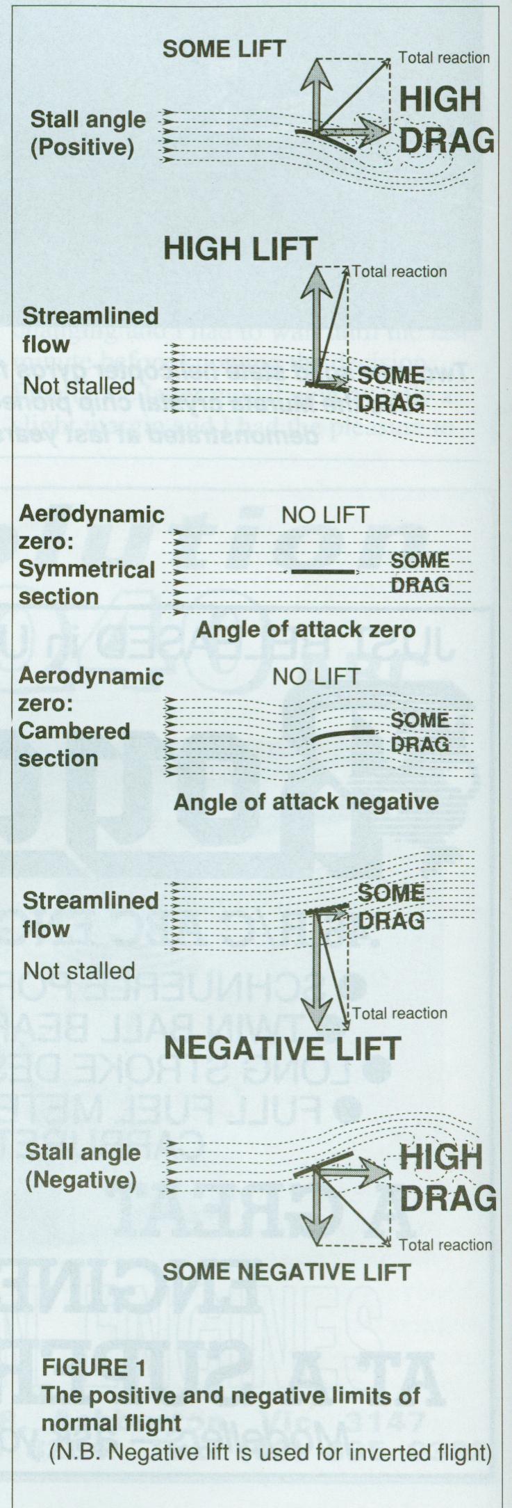
3 CAMBER In an earlier article (RCM News No. 5, page 6-7) it was explained that a slightly arched or cambered piece of card or thin wood, held in an air stream like a wing, will develop lift if it is held at an appropriate angle of attack. Some diagrams from that article are repeated here (Figure 1). If the angle is too large the wing will stall, if too negative (equivalent to upside down in flight), it will stall in the negative sense. These are the practical limits for normal flying. Somewhere between the positive and negative stalling angles there is an angle of no lift, called the aerodynamic zero. If the section is perfectly symmetrical or un cambered this aerodynamic zero coincides with the geometric zero angle of attack. With a cambered surface, aerodynamic zero appears at a negative geometric angle. Some model airplanes and gliders are flown with wing sections which are virtually cambered surfaces of almost no thickness. For example, the best indoor models have very flimsy wing frames covered with the thinnest possible membranes of microfilm. Radio controlled models require some depth in the wing to provide strength and stiffness for flight in the ordinary, turbulent atmosphere. (There are other reasons why a thickened section is often preferable to the thin sheet wing, but discussion of this will be left on one side for the present.) The model flier may think of any aerofoil section as an arched or cambered line buried within the thickness. It may be imagined as the skeleton of the profile. Some of the main features of the wing are determined by the shape of the skeleton just as bone structure determines important human bodily features. The flesh, or thickness of the wing, may be imagined as grown around the camber line, equally on both upper and lower sides. FINDING THE CAMBER The camber line of a profile may be found by plotting a row of points midway between the top and bottom surfaces. For the most accurate results this should be done by the method shown in Figure 2. With a large drawing of the section on plain white paper, fit circles into the outline at as many points as possible. Mark the centres of the circles and join them with a smooth curve. The result is the section camber line. The easiest way of doing this in practice is to draw a whole lot of circles of differing sizes on a piece of tracing paper, using simple school compasses. Slide the tracing paper about over the section drawing to a places where a circle fits, just touching the top and bottom surfaces. Prick through the centre. Move the tracing to another position and find another fit, and prick through, repeating with different circles until there is a long curved row of prick marks, which should be joined up to show the camber line. It is not necessary to do this every time a new section is examined. It is useful as an occasional exercise. A rough idea of the camber can be found quickly by measuring, with a ruler or dividers, a few points equidistant between the top and bottom lines, and sketching the curve. Computer programs are available now which do a better job in much less time, once the section ordinates are put into the data bank. Often, information about the camber line is given in some form by the section designer. All these methods lead to the same point. Whatever the external appearance of the section, there is a camber line inside it. The shape of this inner skeleton has fundamental influence on the behavior of the wing in flight. Sections which look superficially alike may differ a good deal in camber. A symmetrical wing section has an un cambered skeleton, a straight line, surrounded by a thickness form which gives exactly the same shape on the top and bottom surfaces of the wing.

4 Any wing which is not absolutely symmetrical has camber. It thus makes no sense whatsoever to speak of a section as 'semi symmetrical', for example. A section which is not perfectly symmetrical is a cambered section and what matters then is the shape of the camber line. A section cannot be semi-cambered any more than someone can be semi-pregnant. Either one is pregnant or one is not. Either a wing is cambered, or it is symmetrical. Knowing the difference, in either case, is important! Some examples are shown in Figure 3. The wing sections here are cambered. The shape of the camber line is indicated in each case. Figure 4 shows another important point. Four sections here, all from the famous NACA four digit series, have the same camber exactly. When a camber line, of a certain shape and amount of curvature, is buried in a thick wing, the external appearance of the profile often produces a section which is biconvex, like the
5 4415. If the same camber line is buried inside a thinner section, very possibly the under surface of the wing will come out flat, or nearly so, like the If the wing is thinner again, the under surface may be partly concave or under cambered, as with the 4410 and even more with the Further thinning approaches the membrane or film type of section. Thickening or thinning a section certainly does make a difference to the way the wing flies, but since the camber is the same in all these examples, those aspects of the wing which are chiefly affected by camber, will be the same. From this it follows that terming a wing section 'flat bottomed', 'bi-convex', under cambered, etc., does not mean a great deal in aerodynamic terms. It is true that flat bottomed wings are slightly easier to build than any other form. For this reason, but only for this reason, there is some value in mentioning this feature. Under cambered wings require slightly more care in covering or skinning, bi-convex wings may need special jigging or propping up during assembly. Using the external appearance of the wing to describe its aerodynamic qualities, is almost always misleading.


6 THE EFFECTS OF CAMBER IN FLIGHT Imagine a wing with a symmetrical section being held at different angles in a steady airflow of constant speed. Such a flow might come from a simple fan. (The situation is artificial, since changing the angle of attack of a real wing brings with it changes in the speed of flight. For the moment ignore this complication.) At zero angle of attack, aerodynamic zero, the symmetrical section creates no lift. As the angle of attack increases the amount of lift it gives also increases. If the angle decreases, the lift decreases. If the angle of attack is negative the lift reverses in direction. (This allows an aircraft to fly upside down.)
7 Over the normal operating range, the relationship of lift to angle of attack is usually proportional. That is, a small angle of attack yields a small lift force, a larger angle produces a larger lift and so on, until the wing begins to stall. Different wing sections stall in different ways, but over a certain range of angles used in normal flight, they all tend to behave very much alike. So long as the flow does not begin to stall the amount of lift is proportional to the angle of attack, above or below the zero lift angle. It is customary and helpful to represent the variations of lift with angle of attack, by drawing a very simple chart, as in Figure 5. Here, the angle of attack is represented along the horizontal line or X axis, and the lift by the vertical or Y axis. The exact units used do not matter at this stage but it is usual to count the angle of attack in degrees. The lift is plotted as the section coefficient of lift or cl. (Small c, small 1, because CL in capital letters usually means something different.) The line showing the relationship between angle of attack and the lift, is called the lift curve. The usual convention is to draw the chart with the lift curve sloping up from left to right. If the model is being flown very close to the stall, the way in which the lift curve behaves at top and bottom becomes important. Some sections stall gradually as the airflow begins to separate from the trailing edge of the wing. In other cases the flow suddenly breaks away from the leading edge and this produces a very sharp stall. Something more will be said about this later. For the moment, it is important to notice that, between the flow separation limits, the chart of lift against angle of attack is practically a straight line. Paradoxically, the part of the lift curve that is interesting to us is not a curve, but a straight line. This neat state of affairs, perfect proportionality between angle of attack and lift, giving a straight lift curve on the chart, is not always exactly true but departures from the straight lift line are usually small and for most practical purposes can be ignored. INTRODUCING CAMBER Now imagine that the symmetrical section shown on the first chart, is bent round as a whole to give it a little camber. Nothing else is changed. (Figure 6). The aerodynamic zero of the cambered section is found at a negative geometric angle, as expected. On varying the angle and few degrees either way, still in the same steady flow, the chart shows the same kind of straight lift line. Not only is the proportionality preserved, but the actual slope of the line is the same. This means that if the angle of attack of the symmetrical section is increased one degree above aerodynamic zero, it will give just the same amount of lift as the cambered section if its angle is also one degree above aerodynamic zero. If we measure all angles from the aerodynamic zero of a wing section, within certain limits, all wing sections are very much alike. The slope of all the lift curves is about the same. (As before, this is not perfectly true in all circumstances but it is very close to correct in practical flying situations.) wing section, within certain limits, all wing sections are very much alike. The slope of all the lift curves is about the same. (As before, this is not perfectly true in all circumstances but it is very close to correct in practical flying situations.)


8 There is a change in upper and lower limits. In the positive direction, the cambered section reaches a higher point on the chart before it stalls. It can produce more lift than the symmetrical profile. Viewing the chart as a whole, we now see the effect of camber on lift more clearly. The lift curve, all the way from negative stall to positive stall, moves up and to the left on the chart. The more pronounced the section camber, as shown by its camber line, the more the lift curve moves to the left and upward. The general shape of the curve as a whole changes very little. This geometrical feature should not be allowed to obscure the fact that the range of angles between aerodynamic zero and the positive stall, is larger for the cambered section and so the total lift is greater. At angles of attack below aerodynamic zero, things are the other way round. Flying upside down with a cambered section, less lift is available.
C-1: Aerodynamics of Airfoils 1 C-2: Aerodynamics of Airfoils 2 C-3: Panel Methods C-4: Thin Airfoil Theory
 ROAD MAP... AE301 Aerodynamics I UNIT C: 2-D Airfoils C-1: Aerodynamics of Airfoils 1 C-2: Aerodynamics of Airfoils 2 C-3: Panel Methods C-4: Thin Airfoil Theory AE301 Aerodynamics I : List of Subjects
No Description Direction Source 1. Thrust
 AERODYNAMICS FORCES 1. WORKING TOGETHER Actually Lift Force is not the only force working on the aircraft, during aircraft moving through the air. There are several aerodynamics forces working together
It should be noted that the symmetrical airfoil at zero lift has no pitching moment about the aerodynamic center because the upper and
 NAVWEPS -81-8 and high power, the dynamic pressure in the shaded area can be much greater than the free stream and this causes considerably greater lift than at zero thrust. At high power conditions the
BUILD AND TEST A WIND TUNNEL
 LAUNCHING INTO AVIATION 9 2018 Aircraft Owners and Pilots Association. All Rights Reserved. UNIT 2 SECTION D LESSON 2 PRESENTATION BUILD AND TEST A WIND TUNNEL LEARNING OBJECTIVES By the end of this lesson,
Aerodynamic Terms. Angle of attack is the angle between the relative wind and the wing chord line. [Figure 2-2] Leading edge. Upper camber.
![Aerodynamic Terms. Angle of attack is the angle between the relative wind and the wing chord line. [Figure 2-2] Leading edge. Upper camber.](/thumbs/82/86661300.jpg "Aerodynamic Terms. Angle of attack is the angle between the relative wind and the wing chord line. [Figure 2-2] Leading edge. Upper camber.") Chapters 2 and 3 of the Pilot s Handbook of Aeronautical Knowledge (FAA-H-8083-25) apply to powered parachutes and are a prerequisite to reading this book. This chapter will focus on the aerodynamic fundamentals
Chapters 2 and 3 of the Pilot s Handbook of Aeronautical Knowledge (FAA-H-8083-25) apply to powered parachutes and are a prerequisite to reading this book. This chapter will focus on the aerodynamic fundamentals
The Fly Higher Tutorial IV
 The Fly Higher Tutorial IV THE SCIENCE OF FLIGHT In order for an aircraft to fly we must have two things: 1) Thrust 2) Lift Aerodynamics The Basics Representation of the balance of forces These act against
Incompressible Potential Flow. Panel Methods (3)
") Incompressible Potential Flow Panel Methods (3) Outline Some Potential Theory Derivation of the Integral Equation for the Potential Classic Panel Method Program PANEL Subsonic Airfoil Aerodynamics Issues
Incompressible Potential Flow Panel Methods (3) Outline Some Potential Theory Derivation of the Integral Equation for the Potential Classic Panel Method Program PANEL Subsonic Airfoil Aerodynamics Issues
PRE-TEST Module 2 The Principles of Flight Units /60 points
 PRE-TEST Module 2 The Principles of Flight Units 1-2-3.../60 points 1 Answer the following questions. (20 p.) moving the plane (4) upward / forward. Opposed to that is 1. What are the names of the four
A Table Top Wind Tunnel You Can Build
 A Table Top Wind Tunnel You Can Build Basic principles of aerodynamics can be studied in the classroom with this simple, inexpensive wind tunnel. All you need to build it is some cardboard boxes, glue,
Trimming and Flying a Hand Launch Glider A basic and beginners guide by Kevin Moseley
 Trimming and Flying a Hand Launch Glider A basic and beginners guide by Kevin Moseley First and foremost, I am by no means a master at what I have done, or do, in hlg or the class. I am fortunate enough
J. Szantyr Lecture No. 21 Aerodynamics of the lifting foils Lifting foils are important parts of many products of contemporary technology.
 J. Szantyr Lecture No. 21 Aerodynamics of the lifting foils Lifting foils are important parts of many products of contemporary technology. < Helicopters Aircraft Gliders Sails > < Keels and rudders Hydrofoils
Flight Corridor. The speed-altitude band where flight sustained by aerodynamic forces is technically possible is called the flight corridor.
 Flight Corridor The speed-altitude band where flight sustained by aerodynamic forces is technically possible is called the flight corridor. The subsonic Boeing 747 and supersonic Concorde have flight corridors
STUDY OF VARIOUS NACA SERIES AEROFOIL SECTIONS AND WING CONTOUR GENERATION USING CATIA V5
 STUDY OF VARIOUS NACA SERIES AEROFOIL SECTIONS AND WING CONTOUR GENERATION USING CATIA V5 Pawan Kumar Department of Aeronautical Engineering, Desh Bhagat University, Punjab, India ABSTRACT Aerofoil is
CFD ANALYSIS OF FLOW AROUND AEROFOIL FOR DIFFERENT ANGLE OF ATTACKS
 www.mechieprojects.com CFD ANALYSIS OF FLOW AROUND AEROFOIL FOR DIFFERENT ANGLE OF ATTACKS PRESENTATION OUTLINE AIM INTRODUCTION LITERATURE SURVEY CFD ANALYSIS OF AEROFOIL RESULTS CONCLUSIONS www.mechieprojects.com
AERODYNAMIC CHARACTERISTICS OF NACA 0012 AIRFOIL SECTION AT DIFFERENT ANGLES OF ATTACK
 AERODYNAMIC CHARACTERISTICS OF NACA 0012 AIRFOIL SECTION AT DIFFERENT ANGLES OF ATTACK SUPREETH NARASIMHAMURTHY GRADUATE STUDENT 1327291 Table of Contents 1) Introduction...1 2) Methodology.3 3) Results...5
TAKEOFF & LANDING IN ICING CONDITIONS
 Original idea from Captain A. Wagner T TAKEOFF & LANDING IN ICING CONDITIONS here have been a number of accidents related to take-off in conditions in which snow and/or other forms of freezing precipitation
ROAD MAP... D-1: Aerodynamics of 3-D Wings D-2: Boundary Layer and Viscous Effects D-3: XFLR (Aerodynamics Analysis Tool)
") Unit D-1: Aerodynamics of 3-D Wings Page 1 of 5 AE301 Aerodynamics I UNIT D: Applied Aerodynamics ROAD MAP... D-1: Aerodynamics of 3-D Wings D-: Boundary Layer and Viscous Effects D-3: XFLR (Aerodynamics
Unit D-1: Aerodynamics of 3-D Wings Page 1 of 5 AE301 Aerodynamics I UNIT D: Applied Aerodynamics ROAD MAP... D-1: Aerodynamics of 3-D Wings D-: Boundary Layer and Viscous Effects D-3: XFLR (Aerodynamics
WHAT IS GLIDER? A light engineless aircraft designed to glide after being towed aloft or launched from a catapult.
 GLIDER BASICS WHAT IS GLIDER? A light engineless aircraft designed to glide after being towed aloft or launched from a catapult. 2 PARTS OF GLIDER A glider can be divided into three main parts: a)fuselage
DEFINITIONS. Aerofoil
 Aerofoil DEFINITIONS An aerofoil is a device designed to produce more lift (or thrust) than drag when air flows over it. Angle of Attack This is the angle between the chord line of the aerofoil and the
Aircraft Design Prof. A.K Ghosh Department of Aerospace Engineering Indian Institute of Technology, Kanpur
 Aircraft Design Prof. A.K Ghosh Department of Aerospace Engineering Indian Institute of Technology, Kanpur Lecture - 12 Design Considerations: Aerofoil Selection Good morning friends. The last lecture
Incompressible Flow over Airfoils
 Road map for Chap. 4 Incompressible Flow over Airfoils Aerodynamics 2015 fall - 1 - < 4.1 Introduction > Incompressible Flow over Airfoils Incompressible flow over airfoils Prandtl (20C 초 ) Airfoil (2D)
Aerodynamic Analysis of a Symmetric Aerofoil
 214 IJEDR Volume 2, Issue 4 ISSN: 2321-9939 Aerodynamic Analysis of a Symmetric Aerofoil Narayan U Rathod Department of Mechanical Engineering, BMS college of Engineering, Bangalore, India Abstract - The
Commentary on the Pietenpol Airfoil
 Commentary on the Pietenpol Airfoil By Michael Shuck, Copyright 2004 Airfoils are really cool things. They don t exist anywhere except on paper or on computer screens or on the profile of a real, three-dimensional
Principles of glider flight
 Principles of glider flight [ Lecture 1: Lift, drag & glide performance ] Richard Lancaster Email: Richard@RJPLancaster.net Twitter: @RJPLancaster ASK-21 illustrations Copyright 1983 Alexander Schleicher
CASE STUDY FOR USE WITH SECTION B
 GCE A level 135/01-B PHYSICS ASSESSMENT UNIT PH5 A.M. THURSDAY, 0 June 013 CASE STUDY FOR USE WITH SECTION B Examination copy To be given out at the start of the examination. The pre-release copy must
AERODYNAMICS I LECTURE 7 SELECTED TOPICS IN THE LOW-SPEED AERODYNAMICS
 LECTURE 7 SELECTED TOPICS IN THE LOW-SPEED AERODYNAMICS The sources of a graphical material used in this lecture are: [UA] D. McLean, Understanding Aerodynamics. Arguing from the Real Physics. Wiley, 2013.
THEORY OF WINGS AND WIND TUNNEL TESTING OF A NACA 2415 AIRFOIL. By Mehrdad Ghods
 THEORY OF WINGS AND WIND TUNNEL TESTING OF A NACA 2415 AIRFOIL By Mehrdad Ghods Technical Communication for Engineers The University of British Columbia July 23, 2001 ABSTRACT Theory of Wings and Wind
Aerofoil Profile Analysis and Design Optimisation
 Journal of Aerospace Engineering and Technology Volume 3, Issue 2, ISSN: 2231-038X Aerofoil Profile Analysis and Design Optimisation Kondapalli Siva Prasad*, Vommi Krishna, B.B. Ashok Kumar Department
A Hare-Lynx Simulation Model
 1 A Hare- Simulation Model What happens to the numbers of hares and lynx when the core of the system is like this? Hares O Balance? S H_Births Hares H_Fertility Area KillsPerHead Fertility Births Figure
Principles of glider flight
 Principles of glider flight [ Lecture 2: Control and stability ] Richard Lancaster Email: Richard@RJPLancaster.net Twitter: @RJPLancaster ASK-21 illustrations Copyright 1983 Alexander Schleicher GmbH &
Measurement of Pressure. The aerofoil shape used in wing is to. Distribution and Lift for an Aerofoil. generate lift due to the difference
 Measurement of Pressure Distribution and Lift for an Aerofoil. Objective The objective of this experiment is to investigate the pressure distribution around the surface of aerofoil NACA 4415 and to determine
The effect of back spin on a table tennis ball moving in a viscous fluid.
 How can planes fly? The phenomenon of lift can be produced in an ideal (non-viscous) fluid by the addition of a free vortex (circulation) around a cylinder in a rectilinear flow stream. This is known as
Theory of Flight Stalls. References: FTGU pages 18, 35-38
 Theory of Flight 6.07 Stalls References: FTGU pages 18, 35-38 Review 1. What are the two main types of drag? 2. Is it possible to eliminate induced drag? Why or why not? 3. What is one way to increase
EXPERIMENTAL ANALYSIS OF FLOW OVER SYMMETRICAL AEROFOIL Mayank Pawar 1, Zankhan Sonara 2 1,2
 EXPERIMENTAL ANALYSIS OF FLOW OVER SYMMETRICAL AEROFOIL Mayank Pawar 1, Zankhan Sonara 2 1,2 Assistant Professor,Chandubhai S. Patel Institute of Technology, CHARUSAT, Changa, Gujarat, India Abstract The
Reduction of Skin Friction Drag in Wings by Employing Riblets
 Reduction of Skin Friction Drag in Wings by Employing Riblets Kousik Kumaar. R 1 Assistant Professor Department of Aeronautical Engineering Nehru Institute of Engineering and Technology Coimbatore, India
THE CURVE OF THE CRICKET BALL SWING AND REVERSE SWING
 Parabola Volume 32, Issue 2 (1996) THE CURVE OF THE CRICKET BALL SWING AND REVERSE SWING Frank Reid 1 It is a well known fact in cricket that the new ball when bowled by a fast bowler will often swing
CHAPTER 9 PROPELLERS
 CHAPTER 9 CHAPTER 9 PROPELLERS CONTENTS PAGE How Lift is Generated 02 Helix Angle 04 Blade Angle of Attack and Helix Angle Changes 06 Variable Blade Angle Mechanism 08 Blade Angles 10 Blade Twist 12 PROPELLERS
Designing a Model Rocket
 Designing a Model Rocket Design Components In the following pages we are going to look at the design requirements for a stable single stage model rocket. From the diagram here you can see that the rocket
BASIC AIRCRAFT STRUCTURES
 Slide 1 BASIC AIRCRAFT STRUCTURES The basic aircraft structure serves multiple purposes. Such as aircraft aerodynamics; which indicates how smooth the aircraft flies thru the air (The Skelton of the aircraft
Lift for a Finite Wing. all real wings are finite in span (airfoils are considered as infinite in the span)
") Lift for a Finite Wing all real wings are finite in span (airfoils are considered as infinite in the span) The lift coefficient differs from that of an airfoil because there are strong vortices produced
Lift for a Finite Wing all real wings are finite in span (airfoils are considered as infinite in the span) The lift coefficient differs from that of an airfoil because there are strong vortices produced
CFD Study of Solid Wind Tunnel Wall Effects on Wing Characteristics
 Indian Journal of Science and Technology, Vol 9(45), DOI :10.17485/ijst/2016/v9i45/104585, December 2016 ISSN (Print) : 0974-6846 ISSN (Online) : 0974-5645 CFD Study of Solid Wind Tunnel Wall Effects on
Aerodynamics Technology 10 Hour - Part 1 Student Workbook Issue: US180/10/2a-IQ-0201a. Lesson Module: 71.18/3 Written by: LJ Technical Dept
 Aerodynamics Technology 1 Hour - Part 1 Issue: US18/1/2a-IQ-21a Copyright 24,. No part of this Publication may be adapted or reproduced in any material form, without the prior written permission of. Lesson
II.E. Airplane Flight Controls
 References: FAA-H-8083-3; FAA-8083-3-25 Objectives Key Elements Elements Schedule Equipment IP s Actions SP s Actions Completion Standards The student should develop knowledge of the elements related to
Flying High. HHJS Science Week Background Information. Forces and Flight
 Flying High HHJS Science Week 2013 Background Information Forces and Flight Flight Background Information Flying is defined as controlled movement through the air. Many things can become airborne but this
Computational Analysis of Cavity Effect over Aircraft Wing
 World Engineering & Applied Sciences Journal 8 (): 104-110, 017 ISSN 079-04 IDOSI Publications, 017 DOI: 10.589/idosi.weasj.017.104.110 Computational Analysis of Cavity Effect over Aircraft Wing 1 P. Booma
SOARING AND GLIDING FLIGHT OF THE BLACK VULTURE
 [ 280 ] SOARING AND GLIDING FLIGHT OF THE BLACK VULTURE BY B. G. NEWMAN* Department of Engineering, University of Cambridge {Received 10 September 1957) INTRODUCTION In 1950 Raspet published an interesting
AF101 to AF109. Subsonic Wind Tunnel Models AERODYNAMICS. A selection of optional models for use with TecQuipment s Subsonic Wind Tunnel (AF100)
") Page 1 of 4 A selection of optional models for use with TecQuipment s Subsonic Wind Tunnel (AF100) Dimpled Sphere Drag Model (from AF109) shown inside the TecQuipment AF100 Wind Tunnel. Cylinder, aerofoils,
Page 1 of 4 A selection of optional models for use with TecQuipment s Subsonic Wind Tunnel (AF100) Dimpled Sphere Drag Model (from AF109) shown inside the TecQuipment AF100 Wind Tunnel. Cylinder, aerofoils,
THE AIRCRAFT IN FLIGHT Issue /07/12
 1 INTRODUCTION This series of tutorials for the CIX VFR Club are based on real world training. Each document focuses on a small part only of the necessary skills required to fly a light aircraft, and by
Low Speed Wind Tunnel Wing Performance
 Low Speed Wind Tunnel Wing Performance ARO 101L Introduction to Aeronautics Section 01 Group 13 20 November 2015 Aerospace Engineering Department California Polytechnic University, Pomona Team Leader:
X-29 Canard Jet. A Simple Depron Foam Build.
 X-29 Canard Jet. A Simple Depron Foam Build. Two full sized X-29 s were built and the first flew in 1984. They were experimental aircraft, testing this unusual configuration of a canard jet with swept
It is also possible to make a more traditional version of the design - which I call Easy Glider - which can be launched by hand in the normal way.
 The Kendal Flyer Designed by David Mitchell The Kendal Flyer is a rubber band launched plane that I designed in 1990. It is possible to make a pure origami version but I prefer this one in which the nose
A COMPUTATIONAL STUDY ON THE DESIGN OF AIRFOILS FOR A FIXED WING MAV AND THE AERODYNAMIC CHARACTERISTIC OF THE VEHICLE
 28 TH INTERNATIONAL CONGRESS OF THE AERONAUTICAL SCIENCES A COMPUTATIONAL STUDY ON THE DESIGN OF AIRFOILS FOR A FIXED WING MAV AND THE AERODYNAMIC CHARACTERISTIC OF THE VEHICLE Jung-Hyun Kim*, Kyu-Hong
Flight Control Systems Introduction
 Flight Control Systems Introduction Dr Slide 1 Flight Control System A Flight Control System (FCS) consists of the flight control surfaces, the respective cockpit controls, connecting linkage, and necessary
Marking films application guide
 Marking films application guide The application techniques that we will describe should help users by making their job easier, or by saving them time. However, we know that all the advice in the world
The Metric Glider. By Steven A. Bachmeyer. Aerospace Technology Education Series
 The Metric Glider By Steven A. Bachmeyer Aerospace Technology Education Series 10002 Photographs and Illustrations The author wishes to acknowledge the following individuals and organizations for the photographs
Aircraft Stability and Control Prof. A. K. Ghosh Department of Aerospace Engineering Indian Institute of Technology-Kanpur. Lecture- 25 Revision
 Aircraft Stability and Control Prof. A. K. Ghosh Department of Aerospace Engineering Indian Institute of Technology-Kanpur Lecture- 25 Revision Yes, dear friends, this is the mann ki baat session for lateral
Wing-Body Combinations
 Wing-Body Combinations even a pencil at an angle of attack will generate lift, albeit small. Hence, lift is produced by the fuselage of an airplane as well as the wing. The mating of a wing with a fuselage
Manual 1: working with cutting films. MANUAL 1. Working with cutting films. March 2017
 Manual 1: working with cutting films. MANUAL 1 R Working with cutting films March 2017 Manual 1: working with cutting films. R 1 NECESSARY TOOLS It goes without saying that you need the right tools if
AE2610 Introduction to Experimental Methods in Aerospace AERODYNAMIC FORCES ON A WING IN A SUBSONIC WIND TUNNEL
 AE2610 Introduction to Experimental Methods in Aerospace AERODYNAMIC FORCES ON A WING IN A SUBSONIC WIND TUNNEL Objectives The primary objective of this experiment is to familiarize the student with measurement
THERMALLING TECHNIQUES. Preface
 DRAFT THERMALLING TECHNIQUES Preface The following thermalling techniques document is provided to assist Instructors, Coaches and Students as a training aid in the development of good soaring skills. Instructors
Lab Report. Objectives:
 Lab Report Introduction: Aerodynamics is the study of forces and motion of objects that fly/move through the air. Studying aerodynamics allows us to measure the forces of lift and drag. Lift allows an
AE Dept., KFUPM. Dr. Abdullah M. Al-Garni. Fuel Economy. Emissions Maximum Speed Acceleration Directional Stability Stability.
 Aerodynamics: Introduction Aerodynamics deals with the motion of objects in air. These objects can be airplanes, missiles or road vehicles. The Table below summarizes the aspects of vehicle performance
Lesson: Pitch Trim. Materials / Equipment Publications o Flight Training Manual for Gliders (Holtz) Lesson 4.4 Using the Trim Control.
 Lesson 4.4 Using the Trim Control.") 11/18/2015 Pitch Trim Page 1 Lesson: Pitch Trim Objectives: o Knowledge o An understanding of the aerodynamics related to longitudinal (pitch) stability o Skill o Use of the pitch trim system to control
11/18/2015 Pitch Trim Page 1 Lesson: Pitch Trim Objectives: o Knowledge o An understanding of the aerodynamics related to longitudinal (pitch) stability o Skill o Use of the pitch trim system to control
Investigation on 3-D Wing of commercial Aeroplane with Aerofoil NACA 2415 Using CFD Fluent
 Investigation on 3-D of commercial Aeroplane with Aerofoil NACA 2415 Using CFD Fluent Rohit Jain 1, Mr. Sandeep Jain 2, Mr. Lokesh Bajpai 3 1PG Student, 2 Associate Professor, 3 Professor & Head 1 2 3
Lift generation: Some misconceptions and truths about Lift
 Review Article Lift generation: Some misconceptions and truths about Lift Federico Bastianello St. Paul s School, London, England. E-mail: bastiaf@stpaulsschool.org.uk DOI: 10.4103/0974-6102.107612 ABSTRACT
Preliminary Analysis of Drag Reduction for The Boeing
 Preliminary Analysis of Drag Reduction for The Boeing 747-400 By: Chuck Dixon, Chief Scientist, Vortex Control Technologies LLC 07. 31. 2012 Potential for Airflow Separation That Can Be Reduced By Vortex
TLC Technology Education Draft
 TLC Technology Education Draft Title: Airplane Design, Construction, and Flight State Standards: C Explore current transportation technologies and their impacts on society and the environment. C Explore
Dillon Thorse Flow Visualization MCEN 4047 Team Poject 1 March 14th, 2013
 Dillon Thorse Flow Visualization MCEN 4047 Team Poject 1 March 14 th, 2013 1 Introduction I have always been entranced by flight. Recently I have been taking flying lessons, and I have been learning the
Parasite Drag. by David F. Rogers Copyright c 2005 David F. Rogers. All rights reserved.
 Parasite Drag by David F. Rogers http://www.nar-associates.com Copyright c 2005 David F. Rogers. All rights reserved. How many of you still have a Grimes rotating beacon on both the top and bottom of the
Turbulence and How to Avoid It
 Turbulence and How to Avoid It Lesson Overview Wind turbines work best when they are exposed to consistent winds moving with constant speed and direction. Turbulence ( swirling winds ) causes problems.
CFD AND EXPERIMENTAL STUDY OF AERODYNAMIC DEGRADATION OF ICED AIRFOILS
 Colloquium FLUID DYNAMICS 2008 Institute of Thermomechanics AS CR, v.v.i., Prague, October 22-24, 2008 p.1 CFD AND EXPERIMENTAL STUDY OF AERODYNAMIC DEGRADATION OF ICED AIRFOILS Vladimír Horák 1, Dalibor
Big News! Dick Kline Inventor of the KF AirFoil Contacts rcfoamfighters.
 Big News! Dick Kline Inventor of the KF AirFoil Contacts rcfoamfighters. (Copy of Email from Dick Kline to rcfoamfighters on 3/28/09) --------------------------------------------------------------------------------
Aerofoil Design for Man Powered Aircraft
 Man Powered Aircraft Group Aerofoil Design for Man Powered Aircraft By F. X. Wortmann Universitat Stuttgart From the Second Man Powered Aircraft Group Symposium Man Powered Flight The Way Ahead 7 th February
ANALYSIS OF AERODYNAMIC CHARACTERISTICS OF A SUPERCRITICAL AIRFOIL FOR LOW SPEED AIRCRAFT
 ANALYSIS OF AERODYNAMIC CHARACTERISTICS OF A SUPERCRITICAL AIRFOIL FOR LOW SPEED AIRCRAFT P.Sethunathan 1, M.Niventhran 2, V.Siva 2, R.Sadhan Kumar 2 1 Asst.Professor, Department of Aeronautical Engineering,
"Aircraft setup is a constant process really. Every
 The R/C Aircraft Proving Grounds - Aerobatics Setup Set Up for Success by: Douglas Cronkhite "Aircraft setup is a constant process really. Every time something is changed, there is the chance it will affect
THE INNER WORKINGS OF A SIPHON Jacques Chaurette p. eng. January 2003
 THE INNER WORKINGS OF A SIPHON Jacques Chaurette p. eng. www.lightmypump.com January 2003 Synopsis The objective of this article is to explain how a siphon works. The difference between low pressure, atmospheric
How to Do Flight Testing for TARC. Trip Barber NAR TARC Manager
 How to Do Flight Testing for TARC Trip Barber NAR TARC Manager The TARC Cycle Learn the rules and basic rocketry Design and fly your rocket on the computer Build your rocket to your design with real hardware
DOWNFORCE BALANCE. The Downforce Balance graph (shown at the left) illustrates which areas of the vehicle this product affects.
 illustrates which areas of the vehicle this product affects.") OVERVIEW Spanning 67 (or 61) inches over its optimized 3D airfoil shape, the APR Performance GTC-300 Adjustable Wing supplies maximum downforce in sports and touring car applications. DOWNFORCE BALANCE
OVERVIEW Spanning 67 (or 61) inches over its optimized 3D airfoil shape, the APR Performance GTC-300 Adjustable Wing supplies maximum downforce in sports and touring car applications. DOWNFORCE BALANCE
Preliminary design of a high-altitude kite. A flexible membrane kite section at various wind speeds
 Preliminary design of a high-altitude kite A flexible membrane kite section at various wind speeds This is the third paper in a series that began with one titled A flexible membrane kite section at high
AIRFLOW GENERATION IN A TUNNEL USING A SACCARDO VENTILATION SYSTEM AGAINST THE BUOYANCY EFFECT PRODUCED BY A FIRE
 - 247 - AIRFLOW GENERATION IN A TUNNEL USING A SACCARDO VENTILATION SYSTEM AGAINST THE BUOYANCY EFFECT PRODUCED BY A FIRE J D Castro a, C W Pope a and R D Matthews b a Mott MacDonald Ltd, St Anne House,
Table of Contents. Career Overview... 4
 Table of Contents Career Overview.................................................. 4 Basic Lesson Plans Hot-Air Balloons Activity 1 Your First Hot-Air Balloon.... 5 Activity 2 Surface Area and Volume...
OUTLINE FOR Chapter 4
 16/8/3 OUTLINE FOR Chapter AIRFOIL NOMENCLATURE The leaing ege circle: (usually raius =. chor length c) The trailing ege: The chor line: Straight line connecting the center of leaing ege circle an the
Subsonic wind tunnel models
 aerodynamics AF1300a to AF1300l A selection of optional models for use with TecQuipment s Subsonic Wind Tunnel (AF1300) Dimpled Sphere Drag Model (from AF1300j) shown inside the TecQuipment AF1300 Wind
Aerodynamically Efficient Wind Turbine Blade S Arunvinthan 1, Niladri Shekhar Das 2, E Giriprasad 3 (Avionics, AISST- Amity University, India)
") International Journal of Engineering Science Invention ISSN (Online): 2319 6734, ISSN (Print): 2319 6726 Volume 3 Issue 4ǁ April 2014ǁ PP.49-54 Aerodynamically Efficient Wind Turbine Blade S Arunvinthan
International Journal of Engineering Science Invention ISSN (Online): 2319 6734, ISSN (Print): 2319 6726 Volume 3 Issue 4ǁ April 2014ǁ PP.49-54 Aerodynamically Efficient Wind Turbine Blade S Arunvinthan
Shedding Light on Motion Episode 4: Graphing Motion
 Shedding Light on Motion Episode 4: Graphing Motion In a 100-metre sprint, when do athletes reach their highest speed? When do they accelerate at the highest rate and at what point, if any, do they stop
A Simple Horizontal Velocity Model of a Rising Thermal Instability in the Atmospheric Boundary Layer
 A Simple Horizontal Velocity Model of a Rising Thermal Instability in the Atmospheric Boundary Layer (In other words, how to take a closer look at downwind thermal drift) Abstract This pilot, as well as
Experimental Procedure
 1 of 15 9/13/2018, 12:47 PM https://www.sciencebuddies.org/science-fair-projects/project-ideas/sports_p060/sports-science/physics-of-baseball-hit-charts (http://www.sciencebuddies.org/science-fairprojects/project-ideas/sports_p060/sports-science/physics-of-baseball-hit-charts)
VIII.A. Straight and Level Flight
 VIII.A. Straight and Level Flight References: FAA-H-8083-3; FAA-H-8083-25 Objectives Key Elements Elements Schedule Equipment IP s Actions SP s Actions Completion Standards The student should develop the
GLIDING NEW ZEALAND ADVISORY CIRCULAR MYLAR SEALS. This is an Uncontrolled Document. Issued September 2004
 GLIDING NEW ZEALAND ADVISORY CIRCULAR MYLAR SEALS This is an Uncontrolled Document Issued September 2004 Holder s Name: Address: COPYRIGHT 1999 GLIDING NEW ZEALAND INC. No part of this Advisory Circular
PERFORMANCE MANEUVERS
 Ch 09.qxd 5/7/04 8:14 AM Page 9-1 PERFORMANCE MANEUVERS Performance maneuvers are used to develop a high degree of pilot skill. They aid the pilot in analyzing the forces acting on the airplane and in
Advanced Hydraulics Prof. Dr. Suresh A. Kartha Department of Civil Engineering Indian Institute of Technology, Guwahati
 Advanced Hydraulics Prof. Dr. Suresh A. Kartha Department of Civil Engineering Indian Institute of Technology, Guwahati Module - 4 Hydraulic Jumps Lecture - 1 Rapidly Varied Flow- Introduction Welcome
WIND-INDUCED LOADS OVER DOUBLE CANTILEVER BRIDGES UNDER CONSTRUCTION
 WIND-INDUCED LOADS OVER DOUBLE CANTILEVER BRIDGES UNDER CONSTRUCTION S. Pindado, J. Meseguer, J. M. Perales, A. Sanz-Andres and A. Martinez Key words: Wind loads, bridge construction, yawing moment. Abstract.
HEFAT th International Conference on Heat Transfer, Fluid Mechanics and Thermodynamics July 2012 Malta
 HEFAT212 9 th International Conference on Heat Transfer, Fluid Mechanics and Thermodynamics 16 18 July 212 Malta AN EXPERIMENTAL STUDY OF SWEEP ANGLE EFFECTS ON THE TRANSITION POINT ON A 2D WING BY USING
PSY201: Chapter 5: The Normal Curve and Standard Scores
 PSY201: Chapter 5: The Normal Curve and Standard Scores Introduction: Normal curve + a very important distribution in behavior sciences + three principal reasons why... - 1. many of the variables measured
Attitude Instrument Flying and Aerodynamics
 Attitude Instrument Flying and Aerodynamics 2.1 TURNS 1. An airplane requires a sideward force to make it turn. a. When the airplane is banked, lift (which acts perpendicular to the wingspan) acts not
Ship Resistance and Propulsion Prof. Dr. P. Krishnankutty Ocean Department Indian Institute of Technology, Madras
 Ship Resistance and Propulsion Prof. Dr. P. Krishnankutty Ocean Department Indian Institute of Technology, Madras Lecture - 6 Bulbous Bow on Ship Resistance Welcome back to the class we have been discussing
What is a boomerang? History of boomerangs Features and types of a boomerang Basic aerodynamics of a boomerang Why does a boomerang work?
 Outline What is a boomerang? History of boomerangs Features and types of a boomerang Basic aerodynamics of a boomerang Why does a boomerang work? Fabrication of a boomerang Throwing techniques What is
Drag Divergence and Wave Shock. A Path to Supersonic Flight Barriers
 Drag Divergence and Wave Shock A Path to Supersonic Flight Barriers Mach Effects on Coefficient of Drag The Critical Mach Number is the velocity on the airfoil at which sonic flow is first acquired If
NSRCA Club or Novice Class. Maneuver Descriptions. And. Suggested Downgrades
 NSRCA Club or Novice Class Maneuver Descriptions And Suggested Downgrades August 18, 2016 Purpose: The purpose of this guide is to furnish an accurate description of each maneuver of the NSRCA Club or
Flying Wings. By Henry Cole
 Flying Wings By Henry Cole FLYING WINGS REPRESENT THE THEORETICAL ULTIMATE IN AIRCRAFT DESIGN. USE THESE IDEAS, AVAILABLE AFTER A YEAR, OF RESEARCH, TO DEVELOP PRACTICAL MODELS. The rubber version of this