BOAT CREW HANDBOOK Seamanship Fundamentals
|
|
|
- Lynette Hodge
- 6 years ago
- Views:
Transcription

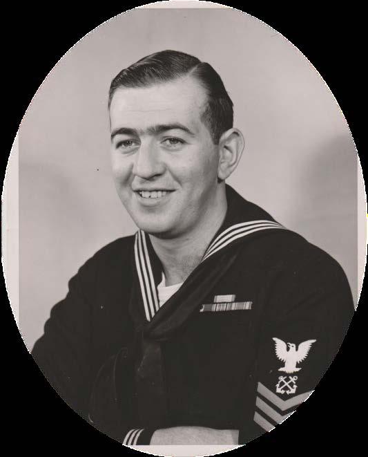

1 BOAT CREW HANDBOOK Seamanship Fundamentals Bernard C. Webber, USCG BCH December 2017
2 Chief Warrant Officer Bernard Webber I reasoned I was a Coast Guard first class boatswain mate. My job was the sea and to save those in peril upon it. On 24 January 2009, Chief Warrant Officer (CWO) Bernard Challen Webber crossed the bar. During his 20-year career, CWO Webber was the recipient of the Gold Lifesaving Medal and responsible for one of the greatest small boat rescues in Coast Guard history. Born in Milton, MA, on 9 May 1928, Webber began his career at sea in 1944 when he joined the Merchant Marine. After serving in the Pacific, he joined the Coast Guard in On 18 February, 1952, BM1 Webber was serving at the Chatham Lifeboat Station when a violent winter storm hit New England. Off the coast of Massachusetts, the SS Pendleton, a tanker originally built for the War Shipping Administration, was enroute from Baton Rouge, LA to Boston with a full load of kerosene and oil. At about 0550, in gale force winds, blinding snow and 60 foot seas, the vessel broke in two. In the bow, were the captain and seven crewmen. Thirty-three men remained in the stern section. There had been no time to issue an S.O.S. The stern section drifted south, about six miles off Cape Cod. The bow section was further offshore. As the men of Chatham Station were busy with the rescue of another tanker, radar picked up the two sections of Pendleton. Visually sighted shortly thereafter, it became apparent that aid could only be rendered by use of the 36-foot Motor Life Boat CG Pendleton s stern section drifted close to shore. At 1755, BM1 Webber and three crewmen left the pier. As CG crossed Chatham s bar, massive waves tossed the small boat, shattering the windshield and tearing the compass from its mount. Knocked to the deck, Webber struggled to regain control. Several times, the engine died as the waves rolled the small vessel in the high seas. As both the weather and visibility worsened, Webber slowed CG The small searchlight finally revealed Pendleton s stern. Maneuvering his small boat around the mangled hulk, he saw men on the tanker s starboard quarter. A Jacob s ladder was tossed over Pendleton s side and the surviving crewmembers started down the ladder. Webber moved CG closer and, one by one, the survivors jumped, landing in the lifeboat or in the sea where the crew assisted them to safety. Of the 33 men aboard the stern section, 32 were saved. With no compass to steer by, and in zero visibility conditions, Webber returned to Fish Pier and a cheering crowd. Initially told that he would receive the Gold Lifesaving Medal, and his crew lesser recognition, Webber refused. Finally, for their actions that day, BM1 Webber and his crew ( EN3 Ander Fitzgerald, SN Richard Livesey and SN Irving Maske) were awarded Gold Lifesaving Medals on 7 May A reluctant hero who disliked publicity, Webber remained in the Coast Guard, rising to the rank of Chief Warrant Officer. His 20-year career included a tour off the coast of Vietnam during Operation Market Time. He retired in Immortalized by the Coast Guard, the cutter Bernard C. Webber (WPC-1101) was commissioned on 14 April 2012.
 b.")
3 Commandant United States Coast Guard US Coast Guard Stop Martin Luther King Jr Ave SE Washington DC Staff Symbol: CG-731 Phone: (202) BCH DEC 13, 2017 BOAT CREW HANDBOOK SEAMANSHIP FUNDAMENTALS BCH Subj: BOAT CREW HANDBOOK SEAMANSHIP FUNDAMENTALS Ref: a. Rescue and Survival Systems Manual, COMDTINST M (series) b. Boat Crew Handbook Boat Operations, BCH PURPOSE. This Handbook explains good seamanship fundamentals and how they apply to boat operations. Major topics within this handbook are Seamanship Fundamentals, Boat Characteristics, Stability, Weather and Oceanography, and Boat Handling. 2. DIRECTIVES AFFECTED. The Boat Crew Seamanship Manual, COMDTINST M C, is canceled. 3. DISCUSSION. The subjects and principles discussed herein include marlinespike seamanship, boat characteristics, stability, weather and oceanography, and boat handling. 4. MAJOR CHANGES. First issue. 5. DISCLAIMER. This guidance is not a substitute for applicable legal requirements, nor is it itself a rule. It is intended to provide operational guidance for Coast Guard personnel and is not intended to nor does it impose legally-binding requirements on any party outside the Coast Guard. 6. IMPACT ASSESSMENT. No impact assessment warranted.
4 BCH ENVIRONMENTAL ASPECT AND IMPACT CONSIDERATIONS. a. The development of this Handbook and the general guidance contained within it have been thoroughly reviewed by the originating office in conjunction with the Office of Environmental Management, and are categorically excluded (CE) under current USCG CE #33 from further environmental analysis, in accordance with Section 2.B.2. and Figure 2-1 of the National Environmental Policy Act Implementing Procedures and Policy for Considering Environmental Impacts, COMDTINST M (series). Because this Handbook contains guidance documents that implement, without substantive change, the applicable Commandant Instruction and other guidance documents, Coast Guard categorical exclusion #33 is appropriate. b. This Handbook will not have any of the following: significant cumulative impacts on the human environment; substantial controversy or substantial change to existing environmental conditions; or inconsistencies with any Federal, State, or local laws or administrative determinations relating to the environment. All future specific actions resulting from the general guidance in this Handbook shall be individually evaluated for compliance with the National Environmental Policy Act (NEPA), Department of Homeland Security (DHS) and Coast Guard NEPA policy, and compliance with all other environmental mandates. 7. DISTRIBUTION. No paper distribution will be made of this Handbook. An electronic version will be located on the Office of Boat Forces (CG-731) Portal site: 8. FORMS/ REPORTS. None 9. REQUESTS FOR CHANGES. To recommend edits and changes to this Handbook, please submit a formal request at the following link: RUSH.JAMES.B J. BRIAN RUSH U.S. Coast Guard Chief, Office of Boat Forces Digitally signed by RUSH.JAMES.B DN: c=us, o=u.s. Government, ou=dod, ou=pki, ou=uscg, cn=rush.james.b Date: :06:12-05'00' 2
5 Boat Crew Handbook Seamanship Fundamental Table of Contents CHAPTER 1 INTRODUCTION SECTION A. PURPOSE OF THIS HANDBOOK SECTION B. HOW TO USE THIS HANDBOOK CHAPTER 2 MARLINSPIKE SEAMANSHIP SECTION A. TYPES AND CHARACTERISTICS OF LINE Line Characteristics A.1. Composition A.2. Line Natural Fiber Line A.3. Composition A.4. Uses of Natural Fiber Line A.5. Limitations A.6. Construction A.7. Plain-Laid Lines Synthetic Fiber Line A.8. Composition A.9. Commonly Used Types A.10. Double-Braided Nylon Line A.11. Plain-Laid Polypropylene Line A.12. Slippage A.13. Considerations A.14. Cutting SECTION B. INSPECTION, HANDLING, MAINTENANCE, AND STOWAGE OF LINE Inspection B.1. Description B.2. Aging B.3. Fiber Wear B.4. Fiber Damage B.5. Chafing B.6. Kinks B.7. Cockles B.8. Cutting B.9. Overloading or Shock-Loading B.10. Rust / Foreign Material B.11. Eye Splices (Double-Braided Nylon Line) Uncoiling and Unreeling B.12. Description B.13. Uncoiling Natural Fiber Laid Line B.14. Unreeling Synthetic Fiber Line Maintenance B.15. Description B.16. Keeping Lines Clean B.17. Using Chafing Gear B.18. Keeping Deck Fittings Clean and Smooth B.19. Watching for Frozen Water B.20. Avoiding Crushing or Pinching Lines B.21. Being Cautious of Sharp Bends B.22. Care and Stowage of Natural Fiber Line B.23. Care of Synthetic Fiber Line Stowing Lines B.24. Description i
6 B.25. Synthetic Fiber Lines B.26. Towline B.27. Coiling B.28. Flemishing a Line SECTION C. KNOTS AND SPLICES Estimating the Length of a Line Breaking Strength Basic Knots C.5. Anatomy of a Knot Splices C.6. Procedure C.7. Eye Splice in Three-Strand Plain-Laid Line C.8. Back Splice in Three-Strand Plain-Laid Line C.9. Short Splice C.10. Eye Splice in Double-Braided Line Whipping C.11. Importance C.12. Temporary Whipping C.13. Permanent Whipping Mousing Hooks and Shackles C.14. Mousing Hooks C.15. Shackles SECTION D. DECK FITTINGS AND LINE HANDLING D.1. Deck Fittings D.2. Line Handling CHAPTER 3 BOAT CHARACTERISTICS SECTION A. BOAT NOMENCLATURE AND TERMINOLOGY A.1. Definitions SECTION B. BOAT CONSTRUCTION Hull Types B.1. Three Types B.2. Factors Influencing Hull Shapes Displacement B.3. Measurement B.4. Gross Tons B.5. Net Tons B.6. Deadweight B.7. Displacement Hull B.8. Planing Hull B.9. Semi-Displacement Hull Keel B.10. Location B.11. Keel Parts B.12. Keel Types Principle Boat Parts B.13. Bow B.14. Stern B.15. Rudder B.16. Propeller B.17. Frames B.18. Decks Hatches and Doors B.19. Hatches B.20. Scuttles B.21. Doors ii
7 Boat Crew Handbook Seamanship Fundamental B.22. Gaskets B.23. Knife Edges B.24. Interior SECTION C. WATERTIGHT INTEGRITY C.1. Closing and Opening Watertight Doors and Hatches C.2. Entering a Closed Compartment After Damage SECTION D. GENERAL BOAT EQUIPMENT D.1. General Boat Equipment List CHAPTER 4 STABILITY SECTION A. UNDERSTANDING STABILITY A.1. Center of Gravity A.2. Buoyancy A.3. Equilibrium A.4. Types of Stability A.5. Moment and Forces SECTION B. LOSING STABILITY B.1. Stability After Damage B.2. Free Surface Effect B.3. Free Communication with the Sea B.4. Effects of Icing B.5. Effects of Downflooding B.6. Effects of Water on Deck CHAPTER 5 WEATHER AND OCEANOGRAPHY SECTION A. WEATHER Wind A.1. Air A.2. Afternoon Wind Increases A.3. Beaufort Wind Scale A.4. Weather Warning Signals Thunderstorms and Lightning A.5. Thunderstorms A.6. Lightning A.7. Distance From a Thunderstorm A.8. Safety A.9. Waterspouts Fog A.10. Description A.11. Advection Fog A.12. Radiation (Ground) Fog A.13. Fog Frequency A.14. Operating in Fog Ice A.15. Salinity A.16. Topside Icing A.17. Frazil Ice A.18. Brash Ice A.19. Ice Floe A.20. Pancake Ice A.21. Clear Ice Forecasting A.22. Sources of Weather Information SECTION B. OCEANOGRAPHY Waves and Surf B.1. Description iii
8 Wind Velocity, Fetch and Duration B.2. Wind Velocity, Fetch and Duration B.3. Wave Systems B.4. Timing B.5. Estimating Wave Height B.6. Breakers B.7. Types of Breakers B.9. Surf B.10. Surf Definitions B.11. Surf Zone Characteristics Currents B.18. Effects on Boat Maneuverability B.19. Crossing the Current B.20. Tide and Tidal Current Changes B.21. Tidal Current Tables B.22. Time and Speed B.23. Current Velocity B.24. Actual vs. Predicted Conditions CHAPTER 6 BOAT HANDLING SECTION A. FORCES Environmental Forces A.3. Close Quarters A.4. Seas A.5. Current A.6. Combined Environmental Forces A.7. Knowing the Vessel s Response Forces Acting on a Vessel A.9. Propulsion and Steering Shaft, Propeller, and Rudder A.11. Propeller Action A.12. Rudder Action Outboard Motors and Stern Drives A.13. Major Differences A.14. Thrust and Directional Control A.15. Propeller Side Force A.16. Vertical Thrust Trim Tabs A.17. Introduction A.18. Trim tabs purpose A.19. How to use trim tabs A.20. Pitch Axis A.21. Roll Axis A.22. Using Your Engine Power Trim and Trim Tabs Together Utilizing Trim Tabs A.23. Head Seas A.24. Following Seas A.25. Astern Propulsion A.26. Correcting Porposing Jacking Plates A.27. Description A.28. Basic Operating Principle A.29. Advantages of Jack Plates A.30. Warnings of Using Jacking Plates A.31. Cavitation Waterjets iv
9 Boat Crew Handbook Seamanship Fundamental A.32. Operation A.33. Thrust and Directional Control A.35. Cavitation SECTION B. BASIC MANEUVERING Learning the Controls B.1. Description B.2. Obstructions / Hazards B.3. Helm Limits B.4. Engine Control Action Check B.5. Joystick Controls B.6. Engine Control Recheck Moving Forward in a Straight Line B.7. Acceleration B.8. Direction Control B.9. Planing B.10. Appropriate Speed B.11. Bank Cushion and Bank Suction B.12. Bow Cushion and Stern Suction B.13. Wake Awareness Turning the Boat with the Helm / Tiller B.14. Description B.15. Pivot Point B.16. Propulsion Type and Turning B.17. Vessel s Turning Characteristics B.18. Loss of Speed B.19. Making Course Changes and Turns in Channels Stopping the Boat B.20. Description B.21. Using Astern Propulsion to Stop the Vessel B.22. Using Astern Propulsion to Stop an Outboard Engine Vessel B.23. Using Full Helm to Stop Forward Way Backing the Vessel B.24. Description B.25. Screw and Rudder B.26. Stern Drives and Outboards B.27. Waterjets Using Asymmetric or Opposed Propulsion (Twin-Screw Theory) B.28. Description B.29. Holding a Course B.30. Changing Vessel Heading Performing Single-Screw Compound Maneuvering (Single-Screw Theory) B.31. Description B.32. Back and Fill (Casting) Performing Duel Waterjet Maneuvering (Waterjet Theory) B.33. Introduction Performing single Waterjet Maneuvering (Waterjet Theory) SECTION C. MANEUVERING NEAR OTHER OBJECTS C.1. Station Keeping C.2. Maneuvering SECTION D. MANEUVERING TO OR FROM A DOCK D.1. General Considerations D.2. Basic Maneuvers D.3. Rules of Thumb SECTION E. MANEUVERING ALONGSIDE ANOTHER VESSEL Determining Approach E.1. Conditions v
10 E.2. Course and Speed E.3. Approach From Leeward and Astern E.4. Line and Fenders Going Alongside E.5. Contacting and Closing In E.6. Using a Sea Painter E.7. Making and Holding Contact E.8. Conducting the Mission E.9. Clearing SECTION F. MANEUVERING IN HEAVY WEATHER/SURF Forces Affecting Boat Handling in Heavy Weather F.1. Description F.2. Rolling F.3. Pitching F.4. Yawing F.5. High Winds Boat Handling F.6. Throttle Management F.7. Managing Power F.8. Staying in the Water F.9. Station Keeping in Heavy Weather F.10. Split Throttle Maneuvers (Heavy Weather Turn, MLB only) Transiting Outbound (Bow-To- Seas) F.11. Crew and Vessel Impact F.12. Speed F.13. Quartering the Seas F.14. Turn and Drag (47 MLB) Lateral Transit in Steep Swells F.15. Steering F.16. Square Up Transiting Stern-To the Seas (Inbound) F.17. Running Inbound F.18. Riding the Back of a Wave F.19. Hard Chine Lockup (47 MLB) F.20. Preventive/Corrective Action Transiting Harbor Entrances, Inlets, or River Entrances F.21. Description F.22. Knowing the Entrance F.23. Transiting When Current Opposes the Seas F.24. Transiting When Current and Seas Coincide Coping with High Winds F.25. Description F.26. Crabbing Through Steady Winds SECTION G. KNOCKDOWN AND ROLLOVER CAUSES G.1. Knockdown or Rollover G.2. Procedures for a Knockdown/ Rollover G.3. Continuing or Returning SECTION H. MANEUVERING IN SURF Surf Operations H.1. Pre-Surf Checks H.2. Surfman Forces Affecting Boat Handling in Surf H.3. Aerated Water H.4. Shallow Water H.5. Changes in Center of Gravity and Trim H.6. External Forces vi
11 Boat Crew Handbook Seamanship Fundamental H.7. Running Stern-To H.8. Broaching or Running Beam-To H.9. Bow into the Surf H.10. Internal Forces H.11. Unsecured or Improperly Stowed Equipment H.12. Changes in Throttle or Helm/Tiller H.13. Pitchpole or Bow-on-Causes Techniques for Operating in Surf H.14. Techniques for Operating in Surf Emergency Procedures: Knockdown or Rollover H.15. Description H.16. Procedures for Involuntary Beaching SECTION I. MANEUVERING IN RIVERS Operating in a Narrow Channel I.1. Bank Cushion I.2. Bank Suction I.3. Combined Effect Turning in a Bend SECTION J. ANCHORING Proper Anchoring J.1. Elements J.2. Terms and Definitions J.3. Reasons for Anchoring J.4. Anchor Types J.5. Danforth Anchor Ground Tackle J.6. Anchor System J.7. Anchor Rode Fittings J.8. Securing the Rode J.9. Description Anchoring Techniques J.10. Procedure J.11. Precautions for Selecting Anchorage Area J.12. Bottom Characteristics J.13. Approaching the Anchorage J.14. Lowering the Anchor J.16. After Anchor is Set J.17. Checking the Anchor Holding J.18. Making Fast J.21. Clearing a Fouled Anchor J.22. Cleaning the Anchor Anchor Stowage J.23. Boat Size J.24. Maintenance J.25. Second Anchor APPENDIX A GLOSSARY... A-1 APPENDIX B LIST OF ACRONYMS... B-1 vii
12 Table of Figures FIGURE 2-1 FIBER ROPE COMPONENTS AND CONSTRUCTION FIGURE 2-2 LINE WITH A KINK FIGURE 2-3 OPENING A NEW COIL OF LINE FIGURE 2-4 LINE FAKED DOWN FIGURE 2-5 CHAFING GEAR FIGURE 2-6 FIGURE EIGHT COILS FIGURE 2-7 FLEMISHING A LINE FIGURE 2-8 BASIC PARTS AND LOOPS FIGURE 2-9 BIGHT AND TURNS FIGURE 2-10 BOWLINE FIGURE 2-11 HALF HITCH FIGURE 2-12 TWO HALF HITCHES FIGURE 2-13 ROLLING HITCH FIGURE 2-14 CLOVE HITCH FIGURE 2-15 SLIP CLOVE HITCH FIGURE 2-16 TIMBER HITCH FIGURE 2-17 TIMBER HITCH WITH TWO HALF HITCHES FIGURE 2-18 SINGLE BECKET BEND/SHEET BEND FIGURE 2-19 DOUBLE BECKET BEND/SHEET BEND FIGURE 2-20 REEF KNOT (SQUARE KNOT) FIGURE 2-21 MONKEY S FIST FIGURE 2-22 FIGURE EIGHT KNOT FIGURE 2-23 CROWN KNOT FIGURE 2-24 SURGEON S KNOT FIGURE 2-25 THREE-STRANDED EYE SPLICE FIGURE 2-26 BACK SPLICE (THREE-STRAND) FIGURE 2-27 SHORT SPLICE FIGURE 2-28 TEMPORARY WHIPPING FIGURE 2-29 PERMANENT WHIPPING FIGURE 2-30 MOUSING A HOOK FIGURE 2-31 MOUSING A SHACKLE FIGURE 2-32 TYPES OF DECK FITTINGS FIGURE 2-33 BACKING PLATE FIGURE 2-34 SECURING A LINE TO PAIRED BITT FIGURE 2-35 SECURING A LINE TO A SINGLE BITT FIGURE 2-36 SECURING A LINE TO A STANDARD CLEAT FIGURE 2-37 SECURING A LINE TO A MOORING CLEAT FIGURE 2-38 DIPPING THE EYE FIGURE 3-1 POSITION AND DIRECTION ABOARD BOATS FIGURE 3-2 TUMBLE HOME HULL DESIGN FIGURE 3-3 DISPLACEMENT HULLS FIGURE 3-4 PLANING HULLS FIGURE 3-5 ROUNDED, CRUISER-TYPE STERN FIGURE 3-6 TRANSOM STERN FIGURE 3-7 RUDDER TYPES FIGURE 3-8 PARTS OF A PROPELLER FIGURE 3-9 TRANSVERSE FRAMING SYSTEM FIGURE 3-10 LONGITUDINAL FRAMING SYSTEM FIGURE 3-11 WATERTIGHT HATCH viii
13 Boat Crew Handbook Seamanship Fundamental FIGURE 3-12 WATERTIGHT COMPARTMENT FIGURE 4-1 STABILITY IN EQUILIBRIUM FIGURE 4-2 HEELING FIGURE 4-3 RIGHTING MOMENT AND CAPSIZING FIGURE 4-4 EFFECTS OF FREE SURFACE FIGURE 4-5 EFFECTS OF LOAD WEIGHT FIGURE 4-6 EFFECTS OF ICING FIGURE 4-7 EFFECTS OF DOWNFLOODING FIGURE 4-8 EFFECTS OF WATER ON DECK FIGURE 5-1 BREAKING SEAS FIGURE 5-2 SUBMARINE VALLEY FIGURE 5-3 WAVE REFRACTION FIGURE 5-4 WAVE REFLECTION FIGURE 5-5 WAVE INTERFERENCE FIGURE 5-6 PLUNGING BREAKER FIGURE 5-7 SPILLING BREAKER FIGURE 5-8 SURGING BREAKER FIGURE 5-9 SURF FIGURE 5-10 WINDOW FIGURE 5-11 HIGH/LOW SIDE OF A WAVE FIGURE 5-13 CLOSEOUT FIGURE 5-14 SHOULDER FIGURE 5-15 RIP CURRENTS FIGURE 5-12 SADDLE... FIGURE 6-1 HIGH CABIN NEAR BOW, LOW FREEBOARD AFT FIGURE 6-2 WIND SHADOW FIGURE 6-3 EFFECTS OF CURRENT FIGURE 6-4 TWIN PROPULSION FIGURE 6-5 PIVOT POINT FIGURE 6-6 SCREW CURRENT FIGURE 6-7 SIDE FORCE FIGURE 6-8 EFFECT OF RUDDER ACTION FIGURE 6-9 LOWER UNIT/OUTDRIVE DIRECTED THRUST FIGURE 6-10 LOWER UNIT/OUTDRIVE SIDE FORCE FIGURE 6-12 TRIM TO OFFSET LOADING CONDITION FIGURE 6-13 PITCH AND ROLL AXIS FIGURE 6-14 JACKING PLATE FIGURE 6-15 WATERJET FIGURE 6-16 THRUST AND DIRECTIONAL CONTROL FIGURE 6-17 ACCELERATED AHEAD FIGURE 6-18 PRONOUNCED SQUAT ON ACCELERATION FIGURE 6-19 BANK CUSHION AND BANK SUCTION FIGURE 6-20 PIVOT POINT, SKID, KICK, INBOARD VS. OUTBOARD FIGURE 6-21 TURNING CHARACTERISTICS FIGURE 6-22 CLEAR A SLIP (NO WIND OR CURRENT, SINGLE-SCREW) FIGURE 6-23 BACKING INTO A SLIP (NO WIND OR CURRENT, SINGLE OUTBOARD/STERN DRIVE) FIGURE 6-24 MOORING LINES FIGURE 6-25 BASIC SPRING LINE MANEUVERS FIGURE 6-26 MAKING USE OF CURRENT FIGURE 6-27 SPLIT THROTTLE MANEUVER FIGURE 6-28 BANK CUSHION AND BANK SUCTION AFFECTS IN A NARROW STRAIGHT CHANNEL FIGURE 6-29 HUG THE POINT: CURRENT ASTERN ix
14 FIGURE 6-30 STAY IN THE BEND: CURRENT ASTERN FIGURE 6-31 APPROACHING SLIGHTLY ON THE BEND SIDE, MIDDLE OF THE CHANNEL: CURRENT ASTERN FIGURE 6-32 HEADING INTO CURRENT FIGURE 6-33 MAIN PARTS OF A DANFORTH ANCHOR FIGURE 6-34 ANCHOR FITTINGS FIGURE 6-35 ANCHORAGE SWING AREA FIGURE 6-36 APPROACHING AN ANCHORAGE FIGURE 6-37 FREEING A FOULED ANCHOR Table of Tables TABLE 2-1 FIBER LINE CHARACTERISTICS TABLE 3-1 GENERAL BOAT EQUIPMENT LIST TABLE 5-1 BEAUFORT WIND SCALE TABLE 5-2 MARINE ADVISORIES AND WARNINGS INCLUDED IN COASTAL AND OFFSHORE FORECASTS TABLE 6-1 SUGGESTED ANCHOR WEIGHTS FOR DANFORTH ANCHORS x
15 Boat Crew Handbook - Seamanship Fundamentals CHAPTER 1 Introduction Section A. Purpose of this Handbook Introduction In this Section The purpose of this Handbook is to explain good seamanship fundamentals and how they apply to boat operations. Major topics within this handbook are Seamsnship Fundamentals, Boat Characteristics, Stability, Weather and Oceanography, and Boat Handling. This Section contains the following information: Title See Page Procedures 1-1 Procedures This Handbook is not intended to cover every contingency that may be encountered during mission execution or training. Successful operations require the exercise of good safety practices, sound judgment and common sense at all levels of command. 1-1

16 Boat Crew Handbook - Seamanship Fundamentals Chapter 1 Introduction Section B. How to Use this Handbook Introduction In this Section Each Part of this Handbook includes its own table of contents and is divided into Chapters. A glossary and list of acronyms are located at the end of this Handbook. This Section contains the following information: Title See Page Layout 1-2 Warnings, Cautions, and Notes 1-2 Layout Warnings, Cautions, and Notes WARNING The first page of each Chapter after this one includes an Introduction and an In this Chapter. The first page of each section includes an Introduction and an In this Section. In the left column of each page are the block titles, which provide descriptive words or phrases for the corresponding block of text across from them. The following definitions apply to Warnings, Cautions, and Notes found throughout the Handbook. Operating procedures or techniques that must be carefully followed to avoid personal injury or loss of life. CAUTION! Operating procedures or techniques that must be carefully followed to avoid equipment damage. NOTE An operating procedure or technique that is essential to emphasize. 1-2
17 CHAPTER 2 Marlinspike Seamanship Introduction In this Chapter Marlinespike seamanship is the art of handling and working with all kinds of line or rope. It includes knotting, splicing, and fancy decorative work. Knowledge of line handling terminology, phrases, and standard communication among the crew is necessary. To be less than proficient may be costly when the safety of life and property depends on the crew s knowledge of marlinespike seamanship. This chapter discusses the following information: (01) Types, characteristics, and care of line, (02) Definitions, (03) Safety practices, (04) Line handling commands, (05) Directions for tying knots and making splices commonly used on boats, (06) Instructions about basic boat line handling, (07) Technical information for determining which line, hooks, and shackles are safe to use. This Chapter contains the following Sections: Section Title See Page A Types and Characteristics of Line 2-2 B Inspection, Handling, Maintenance, and Stowage 2-10 C Knots and Splices 2-20 D Deck Fittings and Line Handling
18 Chapter 2 Marlinspike Seamanship Section A. Types and Characteristics of Line Introduction In this Section The uses for a particular line will depend heavily upon the type and characteristics of the line. This section includes information regarding the different types of line used during boat operations. This section contains the following information: Title See Page Line Characteristics 2-2 Natural Fiber Line 2-5 Synthetic Fiber Line 2-7 Line Characteristics A.1. Composition A.2. Line A.2.a. Material Used A.2.b. Size Lines are made of natural or synthetic fibers twisted into yarns. The yarns are grouped together in such a way as to form strands. Finally, the strands are twisted, plaited, or braided, in various patterns, to form line. Line used on vessels is classified in two different ways: (01) Material used, (02) Size. Lines are categorized as natural fiber or synthetic fiber. Refer to Table 2-1 for fiber line characteristics. The characteristics of the natural and synthetic fiber lines will be explained further in this Section. No matter what the line is made of (natural or synthetic), it is measured the same way, by its circumference or distance around the line. This makes it different from wire rope, which is measured by diameter. Depending on its size, the line is placed into one of the following three categories: (01) Small stuff Up to 1.5" in circumference, (02) Line 1.5" to 5" in circumference, (03) Hawser Everything over 5" in circumference. 2-2
19 Chapter 2 Marlinspike Seamanship LINE CHARACTERISTICS NATURAL FIBER LINE SYNTHETIC FIBER LINE Manila Sisal Cotton Nylon Polyester Polypropylene Polyethylene Strength: Wet strength compared to dry strength Shock load absorption ability Up to 120% Up to 120% Up to 120% 85-90% 1 100% 1 100% 105% Poor Poor Poor Excellent Very good Very good Fair Weight: Specific gravity Able to float No No No No No Yes Yes Elongation: Percent at break 10-12% 10-12% 5-12% 15-28% 12-15% 18-22% 20-24% Creep (extension under sustained load) Very low Very low Moderate Low High High Effects of Moisture: Water absorption of individual fibers Resistance to rot, mildew, and deterioration due to marine organisms Up to 100% Up to 100% Up to 100% % <1.0% None None Poor Very poor Very poor Excellent Excellent Excellent Excellent Degradation: Resistance to UV in sunlight Good Good Good Good Excellent Fair 2 Fair 2 Resistance to aging for properly store rope Good Good Good Excellent Excellent Excellent Excellent Rope Abrasion Resistance: Surface Good Fair Poor Very good 3 Very good 1 Good Fair Internal Good Good Good Very good 3 Excellent 1 Good Good Thermal Properties: High temperature working limit Low temperature working limit 300 F 300 F 300 F 250 F 275 F 200 F 150 F -100 F -100 F -100 F -70 F -70 F -20 F -100 F Melting point Chars 300 F F F 330 F 285 F Chemical Resistance: Effect of acid Will disintegrate in hot diluted and cold concentrated acids Same as manila Same as manila Decompose by strong mineral acids; resistant to weak acids Resistant to most mineral acids; disintegrate by 95% sulfuric acid Very resistant Very resistant Effect of alkalis Poor resistance will lose strength where exposed Same as manila May swell but will not be damaged Little or none No effect cold; slowly disintegrate by strong alkalis at the boil Very resistant Very resistant Effect of organic solvents Fair resistance for fiber, but hydrocarbons will remove protective lubricants on rope Good resistance Poor resistance Resistant. Soluble in some phenolic compounds and in 90% formic acid Generally unaffected; soluble in some phenolic compounds Soluble in chlorinated hydrocarbons at 160 F Same as polypropylene 1 Grades with special over finishes are available to enhance wet strength and abrasion properties. 2 For non-uv stabilized product, consult manufacturer. 3 Dry condition. Under wet condition: Good. Table 2-1 Fiber Line Characteristics 2-3
20 Chapter 2 Seamanship Fundamentals A.2.c. Construction Strands are twisted to either the right or the left. This twisting is the lay of the line. Line may have either a left lay or a right lay depending upon how the strands are twisted together. Line is usually constructed as plain-laid, plaited, and double-braided lines. Figure 2-1 illustrates fiber rope components and construction. The type of construction will depend upon the intended use of the line. Figure 2-1 Fiber Rope Components and Construction 2-4
21 Chapter 2 Seamanship Fundamentals The following describes line types: Line Type Plain-laid Cable-laid Plaited Braided Double-braided Characteristics Made of three strands, right- or left-laid. Most common is right-hand laid. Made of three, right-hand, plain-laid lines laid together to the left to make a larger cable. Made of eight strands, four right-twisted and four lefttwisted. Strands are paired and worked like a four strand braid. Usually made from three strands (sometimes four) braided together. The more common braided lines are hollow-braided, stuffer-braided, solid-braided, and double-braided. Made of two hollow-braided ropes, one inside the other. The core is made of large single yarns in a slack braid. The cover is also made of large single yarns but in a tight braid that compresses and holds the core. This line is manufactured only from synthetics, and about 50% of the strength is in the core. Natural Fiber Line A.3. Composition Natural fiber line is made from organic material, specifically, plant fiber. The following describes the various natural fiber lines: Natural Fiber Line Type Manila Sisal Hemp Cotton Characteristics Made from fibers of the abaca plant and is the strongest and most expensive of the natural fibers. Made from the agave plant and is next in strength to manila, being rated at 80% of manila s strength. Made from the fiber of the stalk of the hemp plant, is now rarely used. Made from natural fibers of the cotton plant, may be three-stranded, right-lay or of braided construction used for fancy work and lashings. 2-5
22 Chapter 2 Seamanship Fundamentals A.4. Uses of Natural Fiber Line CAUTION! A.5. Limitations A.6. Construction A.7. Plain-Laid Lines Natural fiber line, usually manila, hemp or sisal, are used for tying off fenders, securing chafing gear, and doing other small projects where line strength is not a major concern. Braided line is most commonly used for signal halyard, heaving lines, and lead lines. Plain-laid line may be used for securing loose gear, fender lines, and fancy work. Do not use natural fiber line as a towline. Natural fiber line has a lower breaking strength than synthetic fiber line of an equal size, and unlike synthetic line, natural fiber line does not recover after being stretched (elasticity). It is not recommended to be used for loadbearing purposes on boats. Another limitation of natural fiber line is the likelihood of rotting if stowed wet. A close look at a natural fiber line will reveal that the strands are twisted together. They will have either a right or left lay. In plain-laid, three strands are twisted together to the right in an alternating pattern. Because of the number of strands, this line is sometimes called three-strand line. The yarns making up the strands are laid in the opposite direction of the strands. These are twisted together in the opposite direction to make the line. The direction of the twist determines the lay of the line. In the case of plain-laid lines, the yarns are twisted to the right. They are then twisted together to the left to make the strands. The strands are twisted together to the right to make the line (see Figure 2-1). 2-6
23 Chapter 2 Seamanship Fundamentals Synthetic Fiber Line A.8. Composition Synthetic fiber line is made of inorganic (man-made) materials. The characteristics of synthetic fiber line are considerably different from natural fiber line. The differences will vary depending on the type of material from which the line is made. The following identifies the various types of synthetic fiber line used: Nylon Dacron Type Polyethylene and Polypropylene (Polyester) Characteristics A synthetic fiber of great strength, elasticity, and resistance to weather. It comes in twisted, braided, and plaited construction, and can be used for almost any purpose where its slippery surface and elasticity is not a disadvantage. A synthetic fiber of about 80% of the strength of nylon that will only stretch 10% of its original length. A synthetic fiber with about half the strength of nylon, 25% lighter than nylon making it easier to handle, and it floats in water. A.9. Commonly Used Types A.10. Double- Braided Nylon Line A.10.a. Advantages The most common types of synthetic line used on Coast Guard boats are nylon and polypropylene. Because of its superior strength and elasticity, nylon is used where the line must bear a load. When double-braided line is made, the yarns are woven together much like the individual yarns in a piece of cloth are woven. The actual line consists of two hollow braid lines, an inner core and an outer cover. The core is woven into a slack, limp braid from large single yarns. The cover is woven from even larger yarns into a tight braid to cover and compress the core. Double-braided nylon has two other characteristics that increase its strength, elongation and elasticity. Elongation refers to the stretch of the line and elasticity refers to the ability of the line to recover from elongation. Synthetic line will stretch farther and recover better than natural line. Because of this, synthetic line can absorb the intermittent forces and surges resulting from waves or seas much better than natural fiber line. 2-7
24 Chapter 2 Seamanship Fundamentals A.10.b. Limitations A.10.c. Bollard Pull CAUTION! A.11. Plain-Laid Polypropylene Line A.11.a. Advantages A.11.b. Limitations A.12. Slippage A.13. Considerations While its superior strength makes double-braided nylon line a preferred choice for load bearing, there are disadvantages. Because it will stretch further (elongate) and still recover (elasticity), the snap back potential if the line parts is greater than with natural fiber line. Also, if nylon line is doubled and placed under excessive strain, there is a danger that the deck fittings might fail. If that happens, the line will snap back like a rubber band, bringing the deck fitting with it. Additionally, damage to the engine or deck fittings could occur if the bollard pull is exceeded. Bollard pull is the point where the static pulling force becomes such that any increase in engine load could lead to damage to the engine or the towing bitt. Never double a line or use a single line that can withstand more pulling force than the bollard pull of the towing bitt. Yellow-colored polypropylene line is used on Coast Guard boats for life rings and heaving lines. The advantages to this line are high visibility and flotation. The main disadvantage of plain-laid polypropylene line is lack of strength compared to nylon line of equal size. Its loose, course weave makes it easy to splice but susceptible to chafing. Aggravating this is polypropylene s characteristic of deteriorating rapidly when exposed to continuous sunlight. It can, in fact, lose up to 40% of its strength over three months of exposure. For this reason, the line is best kept covered when not in use, and inspected and replaced on a regular basis. Synthetic line slips much easier than natural line. Because of this, it will slip through deck fittings and will not hold knots as well. Care should be taken when bending synthetic line to an object or to another line to ensure the knot will not slip out. One way to help prevent this is to leave a longer tail on the running or bitter end than with natural fiber line. When using synthetic lines consider the following: (01) Synthetic line will slip more easily than natural fiber line. Use caution when paying it or surging it from deck fittings, (02) Beware of slippage when bending synthetic line together or securing, (03) Never stand in a position where exposed to the dangers of snap back if the line parts, (04) Do not double up the line during a towing operation, 2-8
25 Chapter 2 Seamanship Fundamentals (05) Keep working surfaces of bitts free of paint and rust, (06) Do not stand in the bight of a line or directly in line with its direction of pull. CAUTION! To minimize the hazard of being pulled into a deck fitting when a line suddenly surges, ensure all crewmembers stand as far as possible from the equipment. Work the lines with hands at a safe distance from the fittings. This is particularly important during towing operations. A.14. Cutting NOTE The use of a hot knife is the preferred method for cutting nylon and polypropylene line. Using a hot knife eliminates the need for burning the ends. Commercial electric knives, used by sail makers, are available. Some soldering irons can be fit with blades for cutting line. When cutting the line, the blade or saw should not be forced through the line, as the heat will do the job. The best method is to work from the outside in. First, an incision is made around the circumference of the line, and then a cut is made through the center. Remember, when a piece of rope is cut, it will fray. Always finish the end of the line whether before or immediately after cutting the line. 2-9
26 Chapter 2 Seamanship Fundamentals Section B. Inspection, Handling, Maintenance, and Stowage of Line Introduction In this Section Proper maintenance and inspection of line is vital to the completion of the mission as well as the safety of the crew. If a line is damaged or not properly maintained, it could fail, resulting in possible injury to personnel and/or damage to property. This section provides the necessary information regarding basic inspection, uncoiling and unreeling, maintenance, and stowage of line. This section contains the following information: Title See Page Inspection 2-10 Uncoiling and Unreeling 2-13 Maintenance 2-15 Stowing Lines 2-18 Inspection B.1. Description CAUTION! A periodic inspection of all lines used should be made, paying special attention to the following items: (01) Aging, (02) Fiber wear, (03) Fiber damage, (04) Chafing, (05) Kinks, (06) Cockles, (07) Cutting, (08) Overloading or shockloading, (09) Rust/foreign materials, (10) Eye splices. Synthetic double-braided line should not be taken apart for internal inspection. Pay particular attention to black or dark colored lines as their color may hide or mask potential damage. 2-10
27 Chapter 2 Seamanship Fundamentals B.2. Aging B.3. Fiber Wear B.4. Fiber Damage B.5. Chafing Aging affects natural fibers more severely than synthetic. Cellulose, the main component in natural fibers will deteriorate with age, getting more brittle and turning yellow or brownish. When bent over bitts or cleats, the fibers easily rupture and break. During bending, line strength may decrease up to five times. Crewmembers can check for aging by opening the lay of the line and noting the color of the interior fibers. In an old line, they will be gray or dark brown. Aging is not a significant problem for nylon line, though it will change its color with age. As stated before though, polypropylene line does deteriorate rapidly when exposed to sunlight. When natural fiber line is under strain, the friction of the fibers, yarns and strands against each other, causes internal wear. Also, internal wear is a good indication of aging. Upon opening the lay of the line, any presence of a white powdery substance indicates small particles of line worn off by friction. Damage to internal natural fibers occurs when a line under a strain exceeds 75% of its breaking strength. Although this load is not enough to part the line, it is enough to cause some of the internal fibers to break. Internal fiber damage indicates aging and internal wear. With synthetic line, some of the individual synthetic fibers of the line may break if overloaded. These will be visible on the outer surface of the line. Chafing is wear that affects the outer surface of a line, caused by the friction of the line rubbing against any surface. To check for chafing, the outer surface of the line should be visually inspected for frayed threads and broken or flattened strands. With synthetic line, chafing can also cause hardening and fusing of the outer layer. 2-11

28 Chapter 2 Seamanship Fundamentals B.6. Kinks A kink (see Figure 2-2) is a twist or curl caused when the line doubles back on itself. A line with a kink in it should never be placed under strain. The tension will put a permanent distortion in the line. All kinks should be removed before using a line. Figure 2-2 Line with a Kink B.7. Cockles NOTE A cockle (or hockle) is actually a kink in an inner yarn that forces the yarns to the surface. Cockles can be corrected by stretching the line and twisting the free end to restore the original lay. A cockle can reduce line strength by as much as a third. Braided line will not kink or cockle. B.8. Cutting Cutting damage found on line is similar to chafing, but occurs when the line rubs against a sharp edge rather than a rough surface. This will give the appearance as if the line was cut with a knife. Cutting damage to yarns and threads will greatly reduce the effectiveness of the line and can cause failure under strain. 2-12
29 Chapter 2 Seamanship Fundamentals B.9. Overloading or Shock- Loading WARNING Signs that a line was overloaded are elongation and hardness. Line stretched to the point where it will not come back has a decreased diameter. To determine this, the crewmember should place the line under slight tension and measure the circumference of a reduced area and of a normal area. If the circumference is reduced by five percent or more, the line should be replaced. Another indication of synthetic line overloading is hardness to the touch. This can be noticed while gently squeezing the line. Overloaded line shall not be used. A line under strain is dangerous. If it parts, it will do so with a lot of force, depending on the size and type of line, and how much strain it is under when it parts. As a general rule, when a line is under stress, it is important to always keep an eye on it. Standing in line with the strain may cause serious injury if the line parts and snaps back. DO NOT stand directly behind a line that is under strain! If the line were to part, it could snap back and cause injury. B.10. Rust / Foreign Material Rust stains, extending into the cross-section of natural fiber and nylon fiber yarns can lower line strength as much as 40%. Foreign materials (sand, dirt, paint chips, etc.) can get lodged inside the fibers of a line. Once inside the line and under stain, these materials can cause abrasive damage to the line. Care should be taken to cover up lines to prevent foreign materials from entering if they are stowed or in use near work areas. B.11. Eye Splices (Double-Braided Nylon Line) Prior to each use, all eye splices should be inspected on working lines (towline, anchor rode, mooring lines, etc.). Crewmembers should pay particular attention to the area of the line that is tucked back in on itself, ensuring there are no flat spots or areas where the inner core has slipped away leaving only the outer cover. The entire eye should be inspected for chafing and cuts (see Section C of this Chapter for illustrations). Uncoiling and Unreeling B.12. Description NOTE Proper use and care will significantly extend the lifetime of the lines used. Everyone is responsible for protecting lines from damage. Along with good inspections, some of the ways to accomplish this are proper breakout, stowage, and care. Never permanently cover natural fiber line with anything that will prevent the evaporation of moisture. 2-13

30 Chapter 2 Seamanship Fundamentals B.13. Uncoiling Natural Fiber Laid Line To uncoil natural fiber laid line, perform the following procedures: Step Procedure 1 Look inside the center tunnel of the coil to locate the end of the line. 2 Position the coil so the inside line end is at the bottom of the center tunnel. 3 Start uncoiling the line by drawing the inside end up through the top of the tunnel (Figure 2-3). 4 Do not pull on any kinks that develop, as they will develop into permanent strand cockles. If kinks develop, lay the line out straight and remove them before use. Figure 2-3 Opening a New Coil of Line B.14. Unreeling The recommended method for unreeling synthetic fiber lines is to: 2-14

31 Chapter 2 Seamanship Fundamentals Synthetic Fiber Line (01) Insert a pipe through the center and hang the reel off the deck, (02) Draw the line from the lower reel surface. Twisted fiber lines must not be thrown off the reel, as this will cause tangles and kinks. It is recommended that three-strand synthetic lines be faked down on deck and allowed to relax for twenty-four hours. Lengths less than 50 feet will relax in one hour when laid out straight. Fake down doublebraided line in figure eight patterns (Figure 2-4). Figure 2-4 Line Faked Down Maintenance B.15. Description B.16. Keeping Lines Clean While there is nothing that can be done to restore bad line, precautions can be taken to extend the life of lines. Lines should be kept free from grit or dirt. Gritty material can work down into the fibers while a line is relaxed. Under tension, the movement of the grit will act as an abrasive and will cause serious damage to the fibers. 2-15
32 Chapter 2 Seamanship Fundamentals B.17. Using Chafing Gear Chafing gear can be made of old hoses, leather, or heavy canvas. It is used to protect short pieces of line where they run over taff rails, chocks, or other surfaces (Figure 2-5). Figure 2-5 Chafing Gear B.18. Keeping Deck Fittings Clean and Smooth B.19. Watching for Frozen Water B.20. Avoiding Crushing or Pinching Lines B.21. Being Cautious of Sharp Bends Bitts, cleats, and chock surfaces should be kept smooth to reduce line abrasion. Crewmembers should ensure that water does not freeze on lines and that any ice which accumulates is removed. Ice is abrasive and can cut fibers. Crewmembers should avoid walking on, placing loads on, dragging loads over, or in other ways crushing or pinching a line. Bending under a load causes internal abrasion between the strands of the line. If a line has to go around something, a fair lead should be used. A fair lead is any hole, bullnose, lizard, suitably placed roller, sheave, etc., serving to guide or lead a rope in a desired direction. It is important to remember that if a fair lead is not used, the bigger the bend, the less the abrasive effect. 2-16
33 Chapter 2 Seamanship Fundamentals B.22. Care and Stowage of Natural Fiber Line The practices that should be avoided or observed in the maintenance of natural fiber line are as follows: DOs DON Ts (01) Dry line before stowing it in a cool, dark, well-ventilated space, (02) Protect line from weather when possible, (03) Use chafing gear (canvas, short lengths of old fire hose, etc.) where line runs over sharp edges or rough surfaces, (04) Slack off taut lines when it rains. Wet lines shrink and if the line is taut, the resulting strain may be enough to break some of the fibers, (05) Reverse turns on winches periodically to keep out the kinks, (06) Lay right-laid lines clockwise on reels or capstans and left-laid lines counterclockwise until they are broken in, (07) Inspect lines for fiber damage and other wear conditions before each use, (08) Try to tie knots or hitches in new places as much as possible so as not to wear out the line, (09) Occasionally end-for-ending (swap one end for the other) to help reduce excessive wear at certain points. (01) Stow wet or damp line in an unventilated compartment or cover it so that it cannot dry. Mildew will form and weaken the fibers, (02) Subject the line to intense heat or unnecessarily allow it to lie in the hot sun. The lubricant will dry out, thus shortening the useful life of the line, (03) Subject a line to loads exceeding its working load limit. Individual fibers will break, reducing the strength, (04) Allow line to bear on sharp edges or run over rough surfaces, (05) Scrub line. The lubricant will be washed away, and caustics in strong soap may harm the fibers, (06) Try to lubricate line. The lubricant added may do more harm than good, (07) Put a strain on a line with a kink in it, (08) Let wear become localized in one spot, (09) Unbalance line by continued use on winch in same direction. 2-17
 Nylon is not subject to mildew, and it may and should be scrubbed if it becomes slippery because of oil or grease.")
34 Chapter 2 Seamanship Fundamentals B.23. Care of Synthetic Fiber Line Most of the practices in the maintenance of natural fiber line are the same for synthetic fiber line. However, the differences are as follows: (01) Nylon is not subject to mildew, and it may and should be scrubbed if it becomes slippery because of oil or grease. Spots may be removed by cleaning with a 10% solution of mild detergent/degreaser and water, (02) Synthetic line stretches when put under a load. Stowing Lines B.24. Description B.25. Synthetic Fiber Lines To prevent the deteriorating effects of sunlight, chemicals, paints, soaps, and linseed or cottonseed oils, lines should be stored to prevent contact with harmful items or conditions. Synthetic fiber lines are not as susceptible to the effects of moisture as natural fiber lines. They are, however, affected by all of the other conditions and materials that will hurt line. The boat s towline and other synthetic lines should be kept covered or stored in a dark area, when not in use. Synthetic line should not be constantly coiled in the same direction, as doing this tends to tighten the twist. Three-strand synthetic line is often coiled clockwise to reduce a natural tendency to tighten up. It can be coiled in figure eights to avoid kinks when paying out (Figure 2-6). Figure 2-6 Figure Eight Coils 2-18

35 Chapter 2 Seamanship Fundamentals B.26. Towline B.27. Coiling B.28. Flemishing a Line See applicable boat operators handbook for location and procedures for towline stowage. The most common method of stowing the extra line on deck or on the dock after making fast to a cleat is to coil it. Flemishing a line consists of coiling a line against the deck ensures a neat and clean line without it being fouled. It is good for appearance as well for inspections providing a good seaman-like appearance. (Figure 2-7). Figure 2-7 Flemishing a Line 2-19
36 Chapter 2 Seamanship Fundamentals Section C. Knots and Splices Introduction In this Section This section details the procedures regarding the art of knots and splices. This section contains the following information: Title See Page Estimating the Length of a Line 2-20 Breaking Strength 2-21 Basic Knots 2-21 Splices 2-39 Whipping 2-44 Mousing Hooks and Shackles 2-49 Estimating the Length of a Line C.1. Procedure Estimating the length of a line can be a useful skill. One method of doing so is as follows: Step Procedure 1 Hold the end of a length of line in one hand. 2 Reach across with the other hand and pull the line through the first hand, fully extending both arms from the shoulder. The length of line from one hand to the other, across the chest, will be roughly six feet (one fathom). Actually, this distance will be closer to the person s height, but this measure is close enough for a rough and quick estimate of line needed. If more line is needed, the process should be repeated keeping the first hand in place on the line as a marker until the length of line required has been measured off. For example, if 36 feet of line is needed, the procedure should be repeated six times. 2-20
37 Chapter 2 Seamanship Fundamentals Breaking Strength C.2. Knots and Splices Knots are used for pulling, holding, lifting, and lowering. When using line for these purposes, it is often necessary to join two or more lines together. Knots and bends are used for temporary joining, and splices provide a permanent joining. In either case, the breaking strength of the joined line is normally less than the breaking strength of the separated lines. The weakest point in a line is the knot or splice. They can reduce the breaking strength of a line by as much as 50 to 60 percent. A splice, however, is stronger than a knot. Basic Knots C.3. Temporary Knots C.4. Definitions Knots are the intertwining of the parts of one or more lines to secure the lines to themselves, each other (bends), or other objects (hitches). Because knots decrease the strength of the line, they should always be treated as temporary. If something permanent is needed, a splice or seizing can be used. In making knots and splices, the crewmember must know the names for the parts of a line and the basic turns employed. Refer to Figure 2-8 and Figure 2-9 for an examples. Line Part Running End (Bitter End) Standing Part Overhand Loop Description The running end (bitter end) or the free end of a line. It is the end of the line that is worked with. The standing part is the long unused or belayed end of a line. It is the remaining part of the line, including the end that is not worked. The overhand loop is a loop made in a line by crossing the bitter end over the standing part. Underhand Loop The underhand loop is a loop made in the line by crossing the bitter end under the standing part. 2-21
38 Chapter 2 Seamanship Fundamentals Figure 2-8 Basic Parts and Loops 2-22
39 Chapter 2 Seamanship Fundamentals Basic Turns Bight Turn Round Turn Description A bight is a half loop formed by turning the line back on itself. A turn is a single wind or bight of a rope, laid around a belaying pin, post, bollard, or the like. A round turn is a complete turn or encircling of a line about an object, as opposed to a single turn. Figure 2-9 Bight and Turns C.5. Anatomy of a Knot Good knots are easy to tie, easy to untie, and hold well. A good knot will not untie itself. In sailing vernacular, a knot is used to tie a line back upon itself, a bend used to secure two lines together, and a hitch is used to tie a line to a ring, rail or spar. The knots listed below are those most commonly used in boat operations. Crewmembers should learn to tie them well, for the time may come when the skill to do so could decide the outcome of a mission. 2-23
40 Chapter 2 Seamanship Fundamentals C.5.a. Bowline The bowline is a versatile knot and can be used anytime a temporary eye is needed in the end of a line. It also works for tying two lines securely together, though there are better knots for this. An advantage of bowlines is that they do not slip or jam easily. Refer to Figure 2-10 while performing the following procedures: Step Procedure 1 Make an overhand loop in the line the size of the eye desired. 2 Pass the bitter end up through the overhand loop. 3 Bring the bitter end around the standing part and back down through the overhand loop. 4 Pull the knot tight by holding the bitter end and the loop with one hand, and pulling on the standing part with the other. Figure 2-10 Bowline 2-24
41 Chapter 2 Seamanship Fundamentals C.5.b. Half Hitches Hitches are used for temporarily securing a line to objects such as a ring or eye. One of their advantages is their ease in untying. The half hitch is the smallest and simplest hitch. It should be tied only to objects having a righthand pull. Since a single half hitch may slip easily, care should be taken in cases where it will encounter stress. Refer to Figure 2-11 while performing the following procedures: Step Procedure 1 Pass the line around the object. 2 Bring the working end a around the standing part and back under itself. Figure 2-11 Half Hitch 2-25
42 Chapter 2 Seamanship Fundamentals C.5.c. Two Half Hitches To reinforce or strengthen a single half hitch, the line can be tied once more. Two half hitches make a more reliable knot than a single half hitch and can be used to make the ends of a line fast around its own standing part. A round turn or two, secured with a couple of half hitches, is a quick way to secure a line to a pole or spar. Two half hitches are needed to secure a line at an angle where it might slide vertically or horizontally. Refer to Figure 2-12 while performing the following procedures: Step Procedure 1 Take a turn around the object. 2 Bring the running end (bitter end) under and over the standing part and back under itself. 3 Continue by passing bitter end under and over the standing part and back under itself. Figure 2-12 Two Half Hitches 2-26
43 Chapter 2 Seamanship Fundamentals C.5.d. Rolling Hitch (Stopper) A rolling hitch is used to attach one line to another, where the second line is under a strain and cannot be bent. Refer to Figure 2-13 while performing the following procedures: Step Procedure 1 With the bitter end a, make a turn over and under the second line b and pass the link over itself. 2 Pass a over and under b again bringing a through the space between the two lines on the first turn. 3 Pull taut and make another turn with the bitter end a taking it over, then under, then back over itself. 4 Pull taut and tie a half hitch. Figure 2-13 Rolling Hitch 2-27
44 Chapter 2 Seamanship Fundamentals C.5.e. Clove Hitch A clove hitch is preferred for securing a heaving line to a towline. It is the best all-around knot for securing a line to a ring or spar. Correctly tied, a clove hitch will not jam or loosen. However, if it is not tied tight enough, it may work itself out. Reinforcing it with a half hitch will prevent this from happening. Refer to Figure 2-14 while performing the following procedures: Step Procedure 1 Pass the bitter end a around the object so the first turn crosses the standing part. 2 Bring the bitter end a around again and pass it through itself. 3 Pull taut. 4 Reinforce by tying a half hitch. Figure 2-14 Clove Hitch 2-28
45 Chapter 2 Seamanship Fundamentals C.5.f. Slip Clove Hitch A slip clove hitch should be used in lieu of a clove hitch when a quick release is required. It should be tied in the same manner as the clove hitch but finish it with a bight to allow for quick release (see Figure 2-15). It is sometimes used for stowing lines and fenders. It should not be used when working with the line. Figure 2-15 Slip Clove Hitch 2-29
46 Chapter 2 Seamanship Fundamentals C.5.g. Timber Hitch Timber hitches are used to secure a line to logs, spars, planks or other roughsurfaced material, but should not be used on pipes or other metal objects. Refer to Figure 2-16 while performing the following procedures: Step Procedure 1 Tie a half hitch. 2 Continue taking the bitter end a over and under the standing part. 3 Pull the standing part taut. 4 Add two half hitches for extra holding, if necessary (see Figure 2-17). Unless the half hitch can be slipped over the end of the object, tie it before making the timber hitch. Figure 2-16 Timber Hitch 2-30
47 Chapter 2 Seamanship Fundamentals Figure 2-17 Timber Hitch with Two Half Hitches 2-31
48 Chapter 2 Seamanship Fundamentals C.5.h. Single Becket Bend (Sheet Bend) Lines can be lengthened by bending one to another using a becket bend. It is the best knot for connecting a line to an eye splice in another line. It can be readily taken apart even after being under a load. Single becket bends are used to join line of the same size or nearly the same size. It is intended to be temporary. Refer to Figure 2-18 while performing the following procedures: Step Procedure 1 Form a bight in one of the lines to be joined together, line a. 2 Pass the bitter end of the second line b up through the bight formed by the first line a. 3 Wrap the end of line b around the bight in a. 4 Pass the end of b under its own standing part. 5 Pull taut. Figure 2-18 Single Becket Bend/Sheet Bend 2-32
49 Chapter 2 Seamanship Fundamentals C.4.i. Double Becket Bend (Double Sheet Bend) The double becket bend works for joining lines of unequal size. It is tied in the same manner as the single becket bend except for the following variation in step 4 above: Pass line b around and under its standing part twice. (see Figure 2-19) Figure 2-19 Double Becket Bend/Sheet Bend 2-33
50 Chapter 2 Seamanship Fundamentals C.5.j. Reef Knot (Square Knot) Called a square knot by Boy Scouts, the reef knot is one of the most commonly used knots in marlinespike seamanship. Reef knots are primarily used to join two lines of equal size and similar material. Caution should be used if the line is going to be under heavy strain since the reef knot can jam badly and become difficult to untie afterwards. Reef knots are best used to finish securing laces (canvas cover, awning, sail to a gaff, etc.), temporary whippings, and other small stuff. Refer to Figure 2-20 while performing the following procedures: Step Procedure 1 Tie a single overhand knot. 2 Tie a second overhand knot on top so it mirrors (right and left reversed) the first one. The ends should come out together. 3 Draw tight. Figure 2-20 Reef Knot (Square Knot) 2-34
51 Chapter 2 Seamanship Fundamentals C.5.k. The Monkey s Fist Because some lines, such as towlines, are too heavy and awkward to throw any distance, a smaller line called a heaving line which is weighted at one end is used to pass the towline to a disabled vessel. Most heaving lines today are between 75 and 100 feet long and use a softball sized rubber ball at the end to provide the additional weight needed during the throw. Another option would be to tie a monkey s fist at one end of the heaving line. Scrap pieces of line, leather, or cloth can be used instead to provide additional weight needed to throw the heaving line. Refer to Figure 2-21 while performing the following procedures: Step Procedure 1 Lay a bight of the line across the fingers of the left hand, about three and one-half feet from the end, holding the standing part with the left thumb. 2 With fingers separated, take three turns around them. 3 Next take three turns around the first three and at right angles to them. 4 Take the knot off fingers and take an additional three turns around the second three, and inside the first three. 5 Take additional care at this step. Place the core weight (pieces of line, leather, or cloth) into the knot and tighten it down carefully. WARNING Placing pieces of metal (lead or steel) as additional weight in the monkey s fist normally is not to be used since it could cause damage to personnel or property upon impact. 6 After tightening, there should be about 18 inches of line left on the bitter end. This can be brought up and seized alongside to the standing part. 2-35
52 Chapter 2 Seamanship Fundamentals COMPLETE MONKEY FIST Figure 2-21 Monkey s Fist C.5.l. Figure Eight (Stopper) A figure eight knot is an overhand knot with an extra twist. It will prevent the end of a line from feeding through a block or fairlead when loads are involved. It is also easier to untie and does not jam as hard as the over hand knot (see Figure 2-22). Figure 2-22 Figure Eight Knot 2-36
53 Chapter 2 Seamanship Fundamentals C.5.o. Crown Knot A crown knot may be used to prevent an unwhipped line from unlaying. Refer to Figure 2-23 while performing the following procedures: Step Procedure 1 Unlay the strands of the line about 12". 2 Separate the strands and hold them up, facing the with the middle strand. 3 Bend the middle strand a away and form a loop. 4 Bring the right strand b around behind the loop, placing it between strands a and c. 5 Bring strand c over strand b and through the loop formed by strands a. 6 Pull taut by heaving on each of the three strands. 7 Lay the back splice by tucking each strand backup the line. The splicing is done as if making an eye splice. Figure 2-23 Crown Knot 2-37
54 Chapter 2 Seamanship Fundamentals C.5.p. Surgeon s Knot A Surgeon s Knot joins lines of equal or unequal diameters and lines of different materials. When properly tied, the Surgeon s Knot approaches 100- percent line strength. It must be tightened by pulling on all four strands to properly seat the knot. Refer to Figure 2-24 while performing the following procedures: Step Procedure 1 Cross the running ends, putting the left one over the right one. 2 Pass both running ends around the standing parts downward, making an overhand knot. 3 Pass the running ends around the standing parts again, but upward. 4 Cross the running ends again, but placing the end of the right rope on top. 5 Pass the running ends through the loops to create an overhand knot. 6 Tighten the knot. Figure 2-24 Surgeon s Knot 2-38
55 Chapter 2 Seamanship Fundamentals Splices C.6. Procedure C.7. Eye Splice in Three-Strand Plain-Laid Line Splices form a more permanent joining of two lines or two parts of a line. Splicing can be done with many different styles of line including three-strand and doubled-braided. Three-strand lines are unlayed and woven back into themselves or into another line. Double-braided lines go through a series of core/cover removals and tucks in order to complete the splice. Splices are preferred over knots since they allow the line to retain more of its original working strength. The type of splice used depends on the type of joint and the type of line. Eye, back, and short splices will be illustrated for plain laid three-strand line and eye and short (end-for-end) splices will be illustrated for double-braided nylon. The eye splice makes a permanent loop (the eye) in the end of a line. Refer to Figure 2-25 while performing the following procedures: Step Procedure 1 Unlay the strands of the line about 12". 2 Make a bight the size of the eye required. 3 Hold the strands up so the middle strand is facing you. 4 Tuck the middle strand a. NOTE Always tuck the middle strand first, and keep the right-hand strand of the side of the line that is facing toward you. All tucks are made from outboard toward the person tying. 5 Cross-strand b over the strand just tucked and then under the strand just below it. 6 Turn the entire eye splice over and tuck strand c. 7 Pull all strands tight. 8 Pass each strand over the adjacent strand and under the next strand (over & under). The number of tucks depends on the material of the line being worked with. Natural fiber lines should be tucked a minimum of three times. Synthetic fiber lines require four or more tucks to ensure they do not slip. 2-39
56 Chapter 2 Seamanship Fundamentals Figure 2-25 Three-Stranded Eye Splice 2-40
57 Chapter 2 Seamanship Fundamentals C.8. Back Splice in Three-Strand Plain-Laid Line A back splice is commonly used to finish off the end of a line. It can be used on the ends of fender lines. Care should be used when selecting a back splice to finish off a line. The splice will increase the diameter of the line that may cause it to jam or foul when running through a block or deck fitting. If the line must be able to run free, a permanent whipping (see Figure 2-29) on the end is preferred to prevent unraveling. Crewmembers should starting with unlaying the strands at the end, then bending them back on the line, and then interweaving them back through the strands of the standing part. Refer to Figure 2-26 while performing the following procedures: Step Procedure 1 Begin the back splice by tying a crown knot (see Figure 2-26). Each strand goes under and out from its neighbor in the direction of the lay. 2 Pass each strand under itself, just beneath the crown knot. Do not pull these first tucks too tight. 3 Proceed with three more rounds of tucks - over one, under one, as in an eye splice. 4 If preferred, it can be finished by trimming the ends of the strands. Figure 2-26 Back Splice (Three-Strand) 2-41
58 Chapter 2 Seamanship Fundamentals C.9. Short Splice A short splice is used to permanently connect two ends of a line. It is important to note that a short splice is never used in a line that must pass over a pulley or sheave. Refer to Figure 2-27 while performing the following procedures: Step Procedure 1 Unlay the strands of the lines to be spliced, about 12". 2 Bring the ends together by alternating strands. 3 Slide the two ends together, that is, butt them and temporarily seize them with sail twin or tape. 4 Tuck each strand over and under three times, the same way as in eye splicing. (Synthetic line requires an additional tuck.) 5 Remove the seizing. 2-42
59 Chapter 2 Seamanship Fundamentals Figure 2-27 Short Splice 2-43
60 Chapter 2 Seamanship Fundamentals C.10. Eye Splice in Double- Braided Line Splicing a double-braided line entails pulling the core out of the cover and then putting the line back together to make the splice. The basic principle for putting it back together is: (01) The cover goes into the core, (02) Then the core goes back into the cover. Splicing a double-braided line requires the use of special equipment. The pusher and fid are especially designed to splice a certain size of line. The correct measurements supplied by the manufacturer must be used before starting the splice. One mistake in a measurement can result in an improper and dangerous splice. Utilize instructions from the manufacturer(hard copy or website) for splicing a double-braided line. NOTE The following series of steps (which is under copyright by Samson Ocean Systems, Inc.) is reprinted here by permission. Other manufacturers of double-braided line provide splicing instructions. Specific information for splicing should be requested from the appropriate manufacturer. Whipping C.11. Importance The end of a cut line will unravel and fray if not secured with a whipping or back splice. Whippings may be permanent or temporary. 2-44
61 Chapter 2 Seamanship Fundamentals C.12. Temporary Whipping Sometimes called the common whipping, temporary whippings make temporary repairs and secure strands of lines while splicing. They are not very durable and unravel easily if snagged. Whippings are normally made using sail twine, although almost any small stuff will do. Refer to Figure 2-28 while performing the following procedures: Step Procedure 1 Cut a piece of sail twine or small stuff, in length about ten times the circumference of the line being seized. 2 Lay the sail twine or small stuff alongside the line to be whipped (Figure 2-28). 3 Form an overhand loop in the sail twine or small stuff such that the loop extends about ½" beyond the end. 4 Holding end a, make a series of turns over the loop toward the bitter end of the line. Make enough turns so that the length of turns is almost equal to the diameter of the line. 5 Slip end a through the loop c. 6 Secure by pulling loop end from sight by pulling on b. 7 Cut off excess whipping ends or secure them by tying them together with a reef or square knot. 2-45
62 Chapter 2 Seamanship Fundamentals Figure 2-28 Temporary Whipping 2-46
63 Chapter 2 Seamanship Fundamentals C.13. Permanent Whipping Permanent whippings are made to last. To make one, several wraps are made around the line using shot line or waxed nylon. The ends of the whipping line are then sewn across the whipping and through the line. Refer to Figure 2-29 while performing the following procedures: Step Procedure 1 Cut enough of the whipping line to allow for 15 to 20 wraps, with at least a foot of line left over. 2 Secure the whipping line by sewing it through the line. If desired, add strength by sewing through more than once. 3 Wind the whipping line around the line 15 to 20 times, working toward the end of the line. Make sure the body of the whipping covers the secured end of the whipping line. 4 Secure the whipping by sewing through the line. Then bring the line across the whipping and sew it through the line. Do this three or more times, depending on the size of the line. 5 Finish the whipping by sewing through the line a couple more times and cutting the whipping line off close. A pull on the line will pull the end of the whipping line inside, hiding it from view. 2-47
64 Chapter 2 Seamanship Fundamentals Figure 2-29 Permanent Whipping 2-48
65 Chapter 2 Seamanship Fundamentals Mousing Hooks and Shackles C.14. Mousing Hooks A hook is moused to keep slings and straps from slipping out or off the hooks. This is accomplished by either mechanical means or by seizing the hook, using seizing wire or small stuff, from opposite sides (Figure 2-30). Figure 2-30 Mousing a Hook 2-49
66 Chapter 2 Seamanship Fundamentals C.15. Shackles NOTE Shackles are moused to prevent the pin from backing out. This is usually done on screw-pin shackles. Mousing is accomplished by taking several turns, using seizing wire or small stuff, through the pin eye and around the shackle itself in such a way so the pin cannot turn (Figure 2-31). A cable tie (zip tie) can be used as a quick temporary way to mouse a shackle for anchoring and towing. Figure 2-31 Mousing a Shackle 2-50
67 Chapter 2 Seamanship Fundamentals Section D. Deck Fittings and Line Handling Introduction D.1. Deck Fittings This section explains the procedures for securing lines to the various types of deck fittings. Deck fittings are attachments or securing points for lines. They permit easy handling and reduce wear and friction on lines. There are three basic types of deck fittings: (01) Bitts, (02) Cleats, (03) Chocks. Several types of deck fittings are shown in Figure Figure 2-32 Types of Deck Fittings 2-51

68 Chapter 2 Seamanship Fundamentals D.2. Line Handling D.2.a. Using Properly Sized Line D.2.b. Using Backing Plates Cleats may be found on the decks next to the gunwales on each side of a boat used with bitts and cleats to help prevent chafing of the line. The chock provides a smooth surface for the line to run over or through. Because of the difference in the structural design of nonstandard boats, the strength of their deck fittings will vary widely. The size of the deck hardware depends on the size of line to be used for mooring, docking and towing. Cleats are sized by length, and the rule of thumb is the line should be 1 16" in diameter for each inch of cleat ( 3 8" line = 6" cleat, ½" line = 8" cleat. All deck hardware that is used for towing should have backing plates to distribute the load over a wide area (Figure 2-33). The backing plate can be made of pressure treated hardwood or exterior grade plywood, at least twice as thick as the largest bolt diameter. Bolts, not screws should be used. A flat washer and a lock washer must be used with the bolt. The flat washer is three times the bolt diameter. If metal is used, the thickness should be at least the same as the bolt diameter. The use of aluminum is not recommended. Figure 2-33 Backing Plate 2-52


69 Chapter 2 Seamanship Fundamentals D.2.c. Securing a Line to Paired Bitt The following procedures describe how to secure a line to paired bitts (Figure 2-34): Step Procedure 1 Make a complete turn around the near horn. 2 Make several figure eights around both horns. (Size of line and cleats may restrict the number of turns. Minimum of 3 figure eights is the standard). 3 Finish off with a round turn. Figure 2-34 Securing a Line to Paired Bitt 2-53


70 Chapter 2 Seamanship Fundamentals D.2.d. Securing a Line to a Single Bitt A single bitt is a post on the forward or aft deck of a boat. It is used as a cleat or tow bitt. The following procedures describe how to secure a line to a Single Bitt (see Figure 2-35): Step Procedure 1 Make a complete turn around the base of the bitt. 2 Form several figure eights around the horns of the bitt. (Standard is 3 turns.) Figure 2-35 Securing a Line to a Single Bitt 2-54

: Step Procedure 1 Make a complete turn around")

71 Chapter 2 Seamanship Fundamentals D.2.e. Securing a Line to a Cleat The following procedures describe how to secure a line to a cleat when mooring (Figure 2-36): Step Procedure 1 Make a complete turn around the cleat. 2 Lead the line over the top of the cleat and around the horn to form a figure eight. 3 Make two or more additional figure eights to secure the line. Figure 2-36 Securing a Line to a Cleat 2-55


72 Chapter 2 Seamanship Fundamentals D.2.f. Securing a Dock Line to a Cleat The following procedures describe how to temporarly secure a dock line to a cleat (see Figure 2-37): Step Procedure 1 Use a line with an eye already spliced or tie a bowline large enough to loop back over the horns of the cleat. 2 Feed eye of the line through opening. 3 Loop the line back over both horns and pull line taut. Figure 2-37 Securing a Dock Line to a Cleat 2-56

73 Chapter 2 Seamanship Fundamentals D.2.g. Dipping the Eye When two lines with eye splices are placed on a bollard, it may not be possible to remove the bottom line until the top line is removed. By dipping the eye, both lines can be placed for easy removal. The following procedures describe how to dip the eye (see Figure 2-38): Step Procedure 1 Place the eye of one mooring line over the bollard. 2 Take the eye of the second line up through the eye of the first line. 3 Place the eye of the second line over the bollard. Figure 2-38 Dipping the Eye D.2.h. Securing a Towline The towline is the hardest worked line on a boat. When in use, it can carry a tremendous strain and is a possible danger to anyone working near it. Boats have different styles of tow bitts. Towlines should aways be secured (made up) using one complete round turn and three figure eights regardless of the style of bitt. Towlines are secured in this method so they can be easly and safely adjusted or cast off in an emergency. Additional information on the use of towlines is provided in Reference (b). 2-57
74 CHAPTER 3 Boat Characteristics Introduction In this Chapter Knowledge of a boat s characteristics is crucial in performing safe boat operations. All crewmembers must be able to recognize and correctly apply boat related terminology. They must also be able to locate any piece of gear quickly and to operate all equipment efficiently, even in the dark. To accomplish these tasks, crewmembers must be familiar with the boat s layout. Each boat has specific operational characteristics and limitations. These are outlined in the boat s standard handbooks or for non-standard boats, in the Operator s handbook. This chapter contains the following sections: Section Title See Page A Boat Nomenclature and Terminology 3-2 B Boat Construction 3-5 C Watertight Integrity 3-20 D General Boat Equipment
75 Chapter 3 Boat Characteristics Section A. Boat Nomenclature and Terminology Introduction In this Section This section provides definitions to common mariners terms. This section contains the following information: Title See Page Definitions 3-2 A.1. Definitions A.1.a. Bow A.1.b. Amidships A.1.c. Stern A.1.d. Starboard A.1.e. Port A.1.f. Fore and Aft A.1.g. Athwartships As with any profession or skill, there are special terms that mariners use. Many of these terms have a fascinating history. Fellow mariners will expect that these terms will be used in routine conversation. Many of these words will be discussed within this Chapter. The following are common terms used for location, position and direction aboard a boat. Figure 3-1 provides a diagram of a boat with the more common terms noted. The front end of a boat is the bow. Moving toward the bow is going forward; when the boat moves forward, it is going ahead. When facing the bow, the front right side is the starboard bow, and the front left side is the port bow. The central or middle area of a boat is amidships. The right center side is the starboard beam, and the left center side is the port beam. The rear of a boat is the stern. Moving toward the stern is going aft. When the boat moves backwards, it is going astern. Standing at the stern looking forward, the right rear section is the starboard quarter and the left rear section is the port quarter. Starboard is the entire right side of a boat, from bow to stern. Port is the entire left side of a boat, from bow to stern. A line, or anything else, running parallel to the centerline of a boat is fore and aft. A line or anything else running from side to side is athwartships. 3-2
76 Chapter 3 Boat Characteristics A.1.h. Outboard A.1.i. Inboard A.1.j. Going Topside A.1.k. Going Below A.1.l. Going Aloft A.1.m. Weather Deck A.1.n. Lifelines A.1.o. Windward A.1.p. Leeward Outboard is from the centerline of the boat toward either port or starboard side. Inboard is from either side of the boat toward the centerline. However, there is a variation in the use of outboard and inboard when a boat is tied up alongside something (e.g., pier or another vessel). In this example, the side tied up is inboard; the side away is outboard. Going topside is moving from a lower deck to a weather deck or upper deck. Going below is moving from an upper deck to a lower deck. Going aloft is going up into the boat s rigging. The weather deck is the deck exposed to the elements (weather). Lifelines or railings, erected around the edge of weather decks, are all technically called lifelines, although they may have different proper names. Windward is moving in the direction from which the wind is blowing; toward the wind. Leeward is the opposite point from which the wind is blowing; away from the wind. The term is pronounced loo-urd. 3-3
77 Chapter 3 Boat Characteristics Figure 3-1 Position and Direction Aboard Boats 3-4
78 Chapter 3 Boat Characteristics Section B. Boat Construction Introduction Boat construction covers terms that the boat crew will use on a daily basis in normal conversations and in operational situations. Proper understanding of these terms and concepts has importance that an inexperienced sailor may overlook. In this Section This section contains the following information: Title See Page Hull Types 3-5 Displacement 3-8 Keel 3-11 Principle Boat Parts 3-12 Hatches and Doors 3-18 Hull Types B.1. Three Types The hull is the main body of a boat. It consists of a structural framework and a skin or shell plating. The hull may be constructed of many different materials, the most common being metal or fiberglass. A metal skin is usually welded to the structural framework, although riveting is sometimes used. A vessel could be monohull or multi-hull, such as catamarans and trimarans. The three basic types of hull forms based on vessels speed are: (01) Displacement hull, (02) Planing hull, (03) Semi-displacement hull. 3-5
79 Chapter 3 Boat Characteristics B.2. Factors Influencing Hull Shapes Many factors influence hull shapes and affect the boat s buoyancy (its ability to float) and stability (its ability to remain upright). Factors that influence hull shapes are discussed as follows: Flare Factor Tumble home Camber Sheer Chine Transom Length on waterline Length overall Description Flare is the outward turn of the hull as the sides of the hull come up from the waterline. As the boat is launched into the water, the flare increases the boat s displacement and creates a positive buoyant force to float the boat. Tumble home is the reverse of flare and is the shape of the hull as it moves out going from the gunwale to the waterline (see Figure 3-2). This feature is most noticeable when viewing the transom of an older classic cruiser. A deck usually curves athwartships, making it higher at the centerline than at the gunwales so the water flows off the deck. This curvature is called camber. Sheer is the curvature of the main deck from the stem to the stern. When the sheer is pronounced and the bow of the boat is higher than the main deck at amidship, additional buoyancy is provided in the bow. This additional flotation, known as reserve buoyancy, is provided by flare and sheer. The turn of the boat s hull below the waterline is called the chine. It is soft if it is rounded, and hard if it is squared off. Chine affects the boat s speed on turning characteristics. The transom at the stern of the boat is either wide, flat, or curved. The shape of the stern affects the speed, hull resistance, and performance of the boat. The boat s length on waterline (LWL) is the distance from the bow to the stern, measured at the waterline when the boat is stationary. Note that this length changes as the boat rides high or low in the water. The boat s length overall (LOA) is the distance from the foremost to the aftermost points on the boat s hull measured in a straight line. It does not change according to the way the boat sits in the water. 3-6

80 Chapter 3 Boat Characteristics Factor Beam and breadth Draft Draft appendage Trim Description Beam and breadth are measures of a boat s width. Beam is the measurement of the widest part of the hull. Breadth is the measurement of a frame from its port inside edge to its starboard inside edge. Molded beam is the distance between outside surfaces of the shell plating of the hull at its widest point. Extreme breadth is the distance between outside edges of the frames at the widest point of the hull. Draft is the depth of the boat from the actual waterline to the bottom of its keel. Draft appendage is the depth of the boat from the actual waterline to the bottom of its keel or other permanent projection (e.g., propeller, rudder, skeg, etc.), if such a projection is deeper than the keel. The draft is also the depth of water necessary to float the boat. The draft varies according to how the boat lies in the water. Trim is a relative term that refers to the way the boat sets in the water and describes generally its stability and buoyancy. A change in trim may be defined as the change in the difference between drafts forward and aft. A boat is trimmed by the bow when the draft forward increases and the draft is greater than the stern draft. A boat is trimmed by the stern if it is down by the stern. Figure 3-2 Tumble Home Hull Design 3-7
81 Chapter 3 Boat Characteristics Displacement B.3. Measurement Displacement is the weight of a boat and is measured in long tons (2,240 lbs) or pounds. B.4. Gross Tons A gross ton is the entire cubic capacity of a boat expressed in tons of 100 cubic feet. B.5. Net Tons A net ton is the carrying capacity of a boat expressed in tons of 100 cubic feet. It is calculated by measuring the cubic content of the cargo and passenger spaces. B.6. Deadweight Deadweight is the difference between the light displacement and the maximum loaded displacement of a boat and is expressed in long tons or pounds. B.6.a. Light Displacement B.6.b. Loaded Displacement B.7. Displacement Hull Light displacement is the weight of the boat excluding fuel, water, outfit, cargo, crew, and passengers. Loaded displacement is the weight of the boat including fuel, water, outfit, cargo, crew, and passengers. A displacement hull boat pushes away (displaces) water allowing the hull to settle down into the water. Underway, the hull pushes out this water, creating waves (see Figure 3-3). The water separates at the bow and closes at the stern. Tremendous forces work against a displacement hull as the power pushing it and the boat s speed both increase. At maximum displacement speed, there is a distinct bow and stern wave. The length of these waves depends upon the boat s length and speed. (The longer the boat, the longer the wave length.) The bow and the stern ride lower in the water while increasing speed, and the water level alongside, amidships becomes lower than that of the surrounding water. This lower water level is caused by the increase in the velocity of the water flowing under the boat and its interaction with the bow and stern wave. As the boat travels along, it rides in a depression created by its own passage. The displacement hull vessel s maximum speed is determined by the vessel s waterline length. Heavy displacement hulls cannot exceed a speed of 1.34 times the square root of their waterline length without requiring excessive power. This speed is known as critical speed. For details on towing displacement hulls, see Reference (b). 3-8

82 Chapter 3 Boat Characteristics CAUTION! When towing a vessel, be careful not to tow beyond the vessel s design speed. Figure 3-3 Displacement Hulls 3-9
83 Chapter 3 Boat Characteristics B.8. Planing Hull At rest, the planing hull and the displacement hull both displace the water around them. The planing hull reacts nearly the same as a displacement hull when it initially gets underway - it takes considerable power to produce a small increase in speed. However, at a certain point, external forces acting on the shape cause an interesting effect - the hull is lifted up onto the surface of the water (see Figure 3-4). The planing hull skims along the surface of the water whereas the displacement hull always forces water around it. This is called planing. Once on-plane, the power/speed ratio is considerably altered-very little power increase results in a large increase in speed. Crewmembers must apply or reduce power gradually when going from the displacement mode to the planing mode or from the planing mode to the displacement mode. When the power is decreased gradually, the hull makes an even, steady transition, like slowly moving the hand from above the water s surface, through it, and into the liquid below. However, if power is rapidly decreased, the transition will be a rough one, for the hull will slap the surface of the water like the slap resulting by hitting a liquid surface with the hand. Figure 3-4 Planing Hulls Additionally, the rapid re-entry into the displacement mode from above the surface, through the surface, and back into the water causes rapid deceleration as the forces in the water exert pressure against the hull. The effect is like rapidly braking an automobile. 3-10
84 Chapter 3 Boat Characteristics B.9. Semi- Displacement Hull The semi-displacement hull is a combination of characteristics of the displacement hull and the planing hull. This means that up to a certain power level and speed (power/speed ratio), the hull remains in the displacement mode. Beyond this point, the hull is raised to a partial plane. Essentially, the semi-displacement hull, like the displacement hull, always remains in the water; it never gets on-plane. When in the displacement mode, the power/speed ratio is similar to the power/speed ratio described above for the displacement hull. When in the semi-planing mode, it is affected by a combination of forces for the displacement mode and some for the planing mode. Thus, while a small power increase will increase speed, the amount of resulting speed will not be as great as the same power increase would produce for a planing hull. Keel B.10. Location B.11. Keel Parts B.11.a. Frames B.11.b. Stem B.11.c. Sternpost The keel is literally the backbone of the boat. It runs fore and aft along the center bottom of the boat. The following are all integral parts of the keel: (01) Frames, (02) Stem, (03) Sternpost. Frames are attached to the keel, which extend athwartships (from side to side). The skin of the boat is attached to the frames. The keel and the frames strengthen the hull to resist external forces and distribute the boat s weight. The stem is an extension of the forward end of the keel. Although there are a number of common stem shapes, all are normally slanted forward (raked) at an upward angle to reduce water friction. The sternpost is a vertical extension of the aft end of the keel. B.12. Keel Types There are many types of keels. However, in metal boats, there are two types of particular interest: (01) Bar keel, (02) Flat plate keel. 3-11
85 Chapter 3 Boat Characteristics B.12.a. Bar Keel B.12.b. Flat Plate Keel The bar keel is popular because its stiffeners (vertical or upright members which increase strength) protect the boat s hull plating if the boat grounds on a hard bottom. It also reduces rolling. A disadvantage of the bar keel is that it increases the boat s draft, because it extends below the bottom of the boat. The flat plate keel has a plate that is perpendicular to the centerline of the hull. A vertical center keel that runs internal to the hull at the centerline typically supports the flat plate keel. The vertical center keel is often provided with a flange top so that when combined with the flat plate keel the section resembles an I beam. Principle Boat Parts B.13. Bow B.14. Stern The shape of a boat s bow, its profile, form, and construction determine hull resistance as the boat advances through the water. Hull resistance develops from friction and from the wave the hull makes as it moves in the water. Wave-making resistance depends on the boat s speed. The bow of a boat must be designed with enough buoyancy so it lifts with the waves and does not cut through them. The bow flare provides this buoyancy. Boats intended for operation in rough seas and heavy weather have full bows. The bow increases the buoyancy of the forward part of a boat and deflects water and spray. When a boat is heading into a wave, the bow will initially start to cut into the wave. It may be immersed momentarily if the seas are rough. As the bow flare cuts into the wave, it causes the water to fall away from a boat s stern, shifting the center of buoyancy to move forward from the center of gravity. The bow lifts with the wave and the wave passes under the boat, shifting the center of buoyancy aft. This action causes the bow to drop back down and the vessel achieves a level attitude. The shape of the stern affects the speed, resistance, and performance of the boat. It also affects the way water is forced to the propellers. The design of the stern is critical in following seas where the stern is the first part of a boat to meet the waves. If the following waves lift the stern too high, the bow may be buried in the sea. The force of the wave will push the stern causing it to pivot around toward the bow. If this is not controlled, the result can be that a boat broaches or pitch poles. 3-12
86 Chapter 3 Boat Characteristics B.14.a. Rounded Cruiser-Type Stern The rounded, cruiser-type stern presents less flat surface area for a following sea to push upon and tends to split the waves of a following sea, allowing it to pass forward along each side of the boat. Thus, the wave has minimum impact on the attitude of the vessel and provides additional buoyancy for the stern. Crewmembers should always steer into any sideways movement of the stern. For example, when the stern slips to starboard, turn to starboard. It is particularly important that these corrections be made quickly and accurately in short, choppy following seas (see Figure 3-5). Figure 3-5 Rounded, Cruiser-Type Stern B.14.b. Transom Stern The transom stern provides a larger surface area for the seas to push upon and should not be exposed to heavy following seas or surf conditions (see Figure 3-6). Figure 3-6 Transom Stern 3-13
87 Chapter 3 Boat Characteristics B.15. Rudder The rudder controls the direction of the boat and may vary widely in size, design, and method of construction. The shape of the stern, the number of propellers, and the characteristics of the boat determine the type of rudder. The following rudder types are shown in Figure 3-7: (01) Balanced: blade about half forward and half aft of the rudder post, (02) Semi-balanced: more than half of the blade aft of the rudder post, (03) Unbalanced: blade entirely aft of the rudder post. Figure 3-7 Rudder Types B.16. Propeller B.16.a. Propeller Parts B.16.b. Propeller Edge Most boats are driven by one or more propellers, which move in spirals somewhat like the threads on a screw. That is why the propeller is commonly referred to as a screw. The most common propellers are built with three and four blades. The propeller on a single-screw boat typically turns in a clockwise direction (looking from aft forward) as the boat moves forward. Such propellers are referred to as right-handed. On twin-screw boats, the propellers turn in opposite directions, rotating outward from the centerline of the boat. The port propeller is left-handed and turns counterclockwise. The starboard propeller is right-handed and turns clockwise. A propeller consists of blades and a hub. The area of the blade down at the hub is called the root, and its outer edge is called the tip (see Figure 3-8). The edge of the blade that strikes the water first is the leading edge; the opposite is the trailing edge. The diameter of the propeller, the circle made by its tips and its circumference, is called the tip circle. Each blade has a degree of twist from root to tip called pitch (see Figure 3-8). 3-14
88 Chapter 3 Boat Characteristics B.16.c. Pitch Pitch is the distance a propeller advances in one revolution with no slip (see Figure 3-8). Generally, less pitch in the same diameter propeller makes it easier for the engine to reach its preferred maximum RPM; thus, like putting a car in first gear, more power, and sometimes more speed, is available. Similarly, like third gear in a car, more pitch may give more speed, but lower RPMs gives less power. Optimum performance is obtained when pitch is matched to the optimum design speed (RPM) of the engine. Figure 3-8 Parts of a Propeller 3-15
89 Chapter 3 Boat Characteristics B.17. Frames B.17.a. Transverse Frames As previously stated, it is the framing that gives the hull its strength. Frames are of two types: (01) Transverse, (02) Longitudinal. Watertight bulkheads or web frames are located at certain points in the hull to further increase the strength of the hull. Just as the keel is the backbone of the hull, transverse frames are often referred to as ribs. Transverse frames extend athwartships and are perpendicular (vertical or upright) to the keel and are spaced at specified distances (see Figure 3-9). They vary in size from the bow to the stern giving the boat hull its distinct shape when the skin is attached. They are usually numbered from the bow to the stern to help quickly identify a particular location in the interior and, in the event of damage to the hull, to isolate the area of damage. Figure 3-9 Transverse Framing System 3-16
90 Chapter 3 Boat Characteristics B.17.b. Longitudinal Frames Longitudinal frames provide hull strength along the length of the hull (fore and aft) (see Figure 3-10). They run parallel to the keel and at right angles to the transverse frames. In addition to strengthening the hull, the top longitudinal frames provide a skeletal structure over which deck plating is laid. Figure 3-10 Longitudinal Framing System B.18. Decks A deck is a seagoing floor and provides strength to the hull by reinforcing the transverse frames and deck beams. The top deck of a boat is called the weather deck because it is exposed to the elements and is watertight. In general, decks have a slight downward slope from the bow. The slope makes any water taken aboard run aft. A deck also has a rounded, athwartship curve called camber. The two low points of this curve are on the port and starboard sides of the boat where the weather deck meets the hull. Water that runs aft down the sheer line is forced to the port or starboard side of the boat by the camber. When the water reaches one of the sides, it flows overboard through holes, or scuppers, in the side railings. 3-17
91 Chapter 3 Boat Characteristics Hatches and Doors B.19. Hatches In order for a deck with a hatch in it to be watertight, the hatch must be watertight. A weather deck hatch is made watertight by sealing it into a raised framework called a coaming. Hatches operate with quick-acting devices such as wheels or handles, or they may be secured with individual dogs (see Figure 3-11). Figure 3-11 Watertight Hatch B.20. Scuttles B.21. Doors B.22. Gaskets CAUTION! Scuttles are small openings. A scuttle cover, fitted with a gasket and dogs, is used to secure the scuttle. A tool called a T-handle wrench is used to tighten down the scuttle cover dogs. Watertight doors are designed to resist as much pressure as the bulkheads through which they provide access. Some doors have dogs that must be individually closed and opened; others, called quick-acting watertight doors have handwheels or a handle, which operate all dogs at once. Rubber gaskets form tight seals on most watertight closure devices. These gaskets, mounted on the covering surface of the closure device (e.g., door, hatch, scuttle cover), are pressed into a groove around the covering. The gaskets are sealed tight by pressing against a fixed position knife edge. Scuttles must be secured at all times to maintain watertight integrity except when they are open for inspection, cleaning, or painting. They must never be left open overnight or when crewmembers are not actually working or passing through them. 3-18
92 Chapter 3 Boat Characteristics B.23. Knife Edges B.24. Interior Watertight closures must have clean, bright, unpainted, smooth knife edges for the gaskets to press against. A well-fitted watertight closure device with new gaskets will still leak if knife edges are not properly maintained. On some boats, some of the watertight closures have a sealing surface instead of a knife edge. The interior of a boat is compartmentalized by bulkheads, decks, and hatches. With the doors and hatches closed, the space between them becomes watertight and is called a watertight compartment (see Figure 3-12). These watertight compartments are extremely important. Without them, the boat has no watertight integrity and a hole anywhere in the hull will cause it to sink. By dividing the hull into several watertight compartments, the watertight integrity of the boat is significantly increased. One or more of these compartments may flood without causing the boat to sink. A boat could be made unsinkable if its hull could be divided into enough watertight compartments. Unfortunately, excessive compartmentation would interfere with the engineering spaces and restrict movement in the interior spaces. Figure 3-12 Watertight Compartment 3-19
93 Chapter 3 Boat Characteristics Section C. Watertight Integrity Introduction In this Section Watertight integrity describes a compartment or fitting that is designed to prevent the passage of water into it. An important concern in boat operations is to ensure the watertight integrity of the vessel. A boat may sustain heavy damage and remain afloat if watertight integrity is maintained. Doors, hatches, and scuttle covers must be securely dogged while the boat is underway and while it is moored and unattended by crewmembers. This section contains the following information: Title See Page Closing and Opening Watertight Doors and Hatches 3-20 Entering a Closed Compartment After Damage 3-22 C.1. Closing and Opening Watertight Doors and Hatches C.1.a. Closing Watertight doors and hatches will retain their efficiency longer and require less maintenance if they are properly closed and opened as described below. The procedures for closing a watertight door are as follows: Step Procedure 1 Begin by tightening a dog that is opposite the hinges. 2 Place just enough pressure on the dog to keep the door shut. 3 Tighten up the other dogs evenly to obtain uniform pressure all around the closing device. For quick-acting watertight doors, the wheels or handles are turned in the correct direction (clockwise). 3-20
94 Chapter 3 Boat Characteristics C.1.b. Opening If the dogs on watertight doors and hatches open individually, the dog nearest the hinge is opened first. This keeps the closing device from springing and makes loosening the other dogs easier. For quick-acting watertight doors, the wheels or handles are turned in the correct direction (counterclockwise). 3-21
95 Chapter 3 Boat Characteristics C.2. Entering a Closed Compartment After Damage Watertight doors, hatches, and scuttle covers on a damaged boat must not be opened until the following is determined: (01) Flooding did not occur or, if flooded, (02) Further flooding will not occur if the closure is opened. CAUTION! Extreme caution is always necessary when opening compartments below the waterline near hull damage. NOTE Suspect flooding if air escapes when the dogs on a door or hatch are released. 3-22
96 Chapter 3 Boat Characteristics Section D. General Boat Equipment Introduction In this Section All boats should carry basic equipment for routine procedures, such as mooring or anchoring. There may also be equipment that is needed to conduct specific operations, such as towing, dewatering, and search & rescue. Crewmembers must be familiar with the use of the equipment carried onboard and where it is located. A complete listing of required equipment is contained in the Boat Outfit List. Each type of boat should have its own outfit list. This section contains the following information: Title See Page General Boat Equipment List 3-23 D.1. General Boat Equipment List The general equipment found on boats used for multi-mission response a brief statement of the purpose of each item is provided in Table 3-1. Table 3-1 General Boat Equipment List Item Anchors Anchor Lines Chafing Chain Screw Pin Shackle Swivel Thimble Towline Alongside Lines Purpose For anchoring in calm, moderate, and heavy weather. Provides scope to prevent the anchor from dragging. Enables retrieval of the anchor. Serves as an additional towline if necessary. Assists in preventing chafing of the anchor line on the bottom. Attaches chafing chain to shank of anchor. Allows anchor line to spin freely. Prevents chafing of anchor line at connection point with associated hardware. Used for towing astern. Used for alongside towing, joining to kicker hooks, passing a pump, etc. 3-23
97 Chapter 3 Boat Characteristics Table 3-1 (continued) General Boat Equipment List Item Heaving Lines (75' to 100') Grapnel Hook with 100' of Line Boat Hook Kicker Hook Shackles Lead Line (Sounding Pole) First Aid Kit Personnel Survival Kits Heavy Weather Crew Safety Belt Type I PFDs, each with a distress signal light, a whistle, and retroreflective tape Ring Buoy Purpose Used for passing a towline when a close approach is not possible. Used for recovering objects from the water. For reaching dockside lines, fending boat from boat, and recovering objects from water. Attaches to trailer eyebolt on boats for towing or weighing anchor of disabled boats, etc. For weighing a disabled boat s anchor, attaching towing bridles to towlines, attaching towlines to trailer eyebolt, etc. Used in determining water depth and bottom type. For emergency treatment of injuries suffered by crewmembers or survivors. Used by crewmembers in the event of a capsizing or person overboard. For personnel safety during heavy weather or surf operations. Secures a crewmember to the boat. Provides personal flotation support. Keeps the head of an unconscious or injured person out of the water. Worn by crewmembers and given to survivors who are brought onboard. Also worn by survivors who remain on their own boat when it is in tow. Used during person in the water emergencies. Different sizes depending on Platform and size of vessel. 3-24
98 Chapter 3 Boat Characteristics CHAPTER 4 Stability Introduction In this Chapter Stability is defined as the ability of a vessel to return to an upright position after being heeled over. Many forces influence the stability of a vessel in the water, and each type of vessel reacts differently. Boat operators must be aware of how internal forces (those caused by the boat s design and loading) and external forces (those caused by nature) affect the boat. With practice and experience, coxswains learn to anticipate how a vessel being piloted and a vessel being assisted will react to various internal and external forces. Recognizing unstable vessel conditions will lead to safe operations for both the boat crew and persons on a craft in distress. This chapter contains the following sections: Section Title See Page A Understanding Stability 4-2 B Losing Stability
99 Chapter 4 Stability Section A. Understanding Stability Introduction In this Section When a vessel is heeled over in reaction to some external influence, other than damage to the vessel, it tends to either return to an upright position or continue to heel over and capsize. The tendency of a vessel to remain upright is its stability. The greater the tendency to remain upright, and the stronger the force required to heel the vessel over in any direction, the more stability the vessel achieves. The stability of a vessel in the water is very important to all members of a boat crew. Being able to anticipate how the crewmembers vessel and the vessel that is being assisted will react in any given set of circumstances is dependent on the crew s knowledge of stability. Gravity and buoyancy are the two primary forces acting upon a floating vessel that affect stability. Gravity pushes the vessel down into the water, while buoyancy is the force that pushes up from the water to keep the vessel afloat. The interaction of these two forces determines the vessel s stability. This section contains the following information: Title See Page Center of Gravity 4-2 Buoyancy 4-2 Equilibrium 4-3 Types of Stability 4-5 Moment and Forces 4-5 A.1. Center of Gravity A.1.a. Changes in the Center of Gravity A.2. Buoyancy The center of gravity is the point at which the weight of the boat acts vertically downwards. Thus, the boat acts as though all of its weight were concentrated at the center of gravity. Generally, the lower the center of gravity, the more stable the vessel. The center of gravity of a boat is fixed for stability and does not shift unless weight is added, subtracted, or shifted. When weight is added (e.g., vessel takes on water), the center of gravity moves toward the added weight. When the weight is removed, the center of gravity moves in the opposite direction. The buoyancy is the upward force of water displaced by the hull. The force of buoyancy keeps the boat afloat; however, it may be overcome if too much weight is added. 4-2
100 Chapter 4 Stability A.2.a. Center of Buoyancy The center of buoyancy is the center of gravity of displaced water. Similar to the center of gravity, this is the point on which all upward/vertical force is considered to act. It lies in the center of the underwater form of the hull (see Figure 4-1). A.3. Equilibrium When a boat is at rest, the center of buoyancy acting upwards/vertically is below the center of gravity acting downwards. It is at this point that a boat is considered to be in equilibrium. Equilibrium is affected by movement of the center of gravity or center of buoyancy or by some outside forces, such as wind and waves (see Figure 4-1). Figure 4-1 Stability in Equilibrium A.3.a. Rolling When a boat rolls, the force of the center of gravity will move in the same direction as the roll. The downward force of gravity is offset by the upward force of buoyancy and causes the boat to heel. 4-3
101 Chapter 4 Stability A.3.b. Heeling In heeling, the underwater volume of the boat changes shape causing the center of buoyancy to move. The center of buoyancy will move towards the part of the hull that is more deeply immersed. When this happens, the center of buoyancy will no longer be aligned vertically with the center of gravity. The intersection of the vertical line through the center of buoyancy and the vertical centerline is called the metacenter. When the metacentric height (the distance between center of gravity and metacenter) is positive, that is the metacenter is above center and gravity, the center of buoyancy shifts so that it is outboard of the center of gravity. Now the boat is considered to be stable, and the forces of buoyancy and gravity will act to bring the boat back to an upright position. If the center of buoyancy is inboard of the center of gravity, that is the metacentric height is negative, the forces of buoyancy and gravity will tend to roll the boat further towards capsize (see Figure 4-2). Figure 4-2 Heeling 4-4
102 Chapter 4 Stability A.3.c. Listing NOTE If the center of gravity is not on the centerline of the boat, the boat will heel until equilibrium is reached with the center of buoyancy and center of gravity in alignment. This condition is referred to as listing. Heeling is a temporary leaning, listing is a permanent leaning, and both are different from rolling, which is a side-to-side motion. A.4. Types of Stability A.4.a. Longitudinal (Fore and Aft) Stability A.4.b. Transverse (Athwartships) Stability A.5. Moment and Forces A boat has two principle types of stability: (01) Longitudinal, (02) Transverse. A boat is usually much longer than it is wide. Therefore, the longitudinal plane (fore and aft) is more stable than its transverse plane (beam). Longitudinal (fore and aft) stability tends to balance the boat, preventing it from pitching end-over-end (pitch poling). Vessels are designed with enough longitudinal stability to avoid damage under normal circumstances. However, differences in vessel design varies the longitudinal stability characteristics of different vessels depending on the purpose for which a vessel is designed. Some vessels can suffer excessive pitching and offer a very wet and uncomfortable ride during rough sea and weather conditions. Such an uncomfortable ride often affects the endurance and capability of the crew as well as the people on the vessels being assisted. Transverse (athwartships) stability tends to keep the boat from rolling over (capsizing). Additional weight above the center of gravity increases the distance from the center of gravity up to the center of buoyancy. As a result, stability is also decreased. Removal of weight from below the center of gravity also decreases stability. If the center of gravity is raised enough, the boat will become unstable. The force that causes a vessel to return to an even keel, or upright position, is called the vessel s moment. Both static and dynamic forces can reduce stability and moment. Moments, and the internal and external forces that act to increase or decrease the righting moment, are important factors in determining the stability of a vessel at any given point in time. 4-5
103 Chapter 4 Stability A.5.a. Righting Moment and Capsizing A righting moment is the force causing a vessel to react against a roll and return to an even keel. Generally, the broader a boat s beam, the more stable that boat will be, and the less likely it is to capsize. For any given condition of loading, the center of gravity is at a fixed position. As a boat heels, the center of buoyancy moves to the lower side of the boat forming an angle of inclination. Larger changes in the movement of the center of buoyancy will result with any given angle of heel. This change provides greater righting movement up to a maximum angle of inclination. Too much weight added to the side of the vessel that is heeled over can overcome the forces supporting stability and cause the vessel to capsize (see Figure 4-3). A boat may also capsize when aground as the volume of water beneath the vessel decreases and the vessel loses balance. As the amount of water supporting the vessel is reduced, there is a loss of buoyancy force being provided by that water. In addition, the upward force acting at the point of grounding will increase and cause the unsupported hull to fall to one side. Figure 4-3 Righting Moment and Capsizing 4-6
104 Chapter 4 Stability A.5.b. Static and Dynamic Forces A.5.c. Vessel Design Unless acted upon by some external force, a boat that is properly designed and loaded remains on an even keel. The two principle forces that affect stability are static and dynamic forces. (01) Static forces are caused by placement of weight within the hull. Adding weight on one side of a boat s centerline or above its center of gravity usually reduces stability. Flooding or grounding a boat makes it susceptible to static forces which may adversely affect stability. (02) Dynamic forces are caused by actions outside the hull such as wind and waves. Strong gusts of wind or heavy seas, especially in shallow water, may build up a dangerous sea tending to capsize a boat. For a boat crewmember this understanding is useful when approaching a vessel to provide assistance. Observing the vessel s roll can provide some initial indications about the stability of the vessel. (03) Watch the time required for a complete roll from side to side. The time should remain about the same regardless of the severity of the angle or roll. (04) If the time increases significantly or the boat hesitates at the end of the roll, the boat is approaching or past the position of maximum righting effect. Take immediate steps to decrease the roll by changing course or speed, or both. General vessel design features that influence stability include: (01) Size and shape of the hull, (02) Draft of the boat (the distance from the surface of the water to the keel), (03) Trim (the angle from horizontal at which a vessel rides), (04) Displacement, (05) Freeboard, (06) Superstructure size, shape, and weight, (07) Non-watertight openings. Many of these features are discussed in CHAPTER 3 Boat Characteristics. 4-7
105 Chapter 4 Stability Section B. Losing Stability Introduction A vessel may be inclined away from its upright position by certain internal and external influences such as: (01) Waves, (02) Wind, (03) Turning forces when the rudder is put over, (04) Shifting of weights onboard, (05) Addition or removal of weights, (06) Loss of buoyancy (damage). These influences exert heeling moments on a vessel causing it to list (permanent) or heel (temporary). A stable boat does not capsize when subjected to normal heeling moments due to the boat s tendency to right itself (righting moment). B.1. Stability After Damage When assisting a damaged vessel, any change in stability may result in the loss of the vessel. The added weight of assisting personnel or equipment may cause the vessel to lose its righting moment, lose stability, and capsize. This consequence, and the danger involved, must be considered when determining risk to avoid harm to the crew and further damage or loss of a vessel. B.1.a. Stability Risk Management Plan The entire crew must constantly watch for any loss of stability in their own vessel and that of the distressed craft. Crewmembers should not assume that the coxswain has been able to observe all of the warning signs. They should advise the coxswain of stability concerns that may have been overlooked and any warning signs. The following warning signs should be used as a guideline for a Stability Risk Management Plan: (01) Observe the roll of your own boat and, for a distressed vessel, observe its roll upon approaching and when under tow, (02) Be aware of external forces - wind, waves, and water depth, (03) Be aware of control loading, amount of weight and placement, on own and the distressed craft, (04) If necessary, attempt to keep your equipment aboard your vessel when dewatering the vessel, (05) Attempt to tow the distressed vessel only after any loss of stability has been corrected, (06) Adjust course, speed, or both as necessary to decrease rolling or listing, (07) Avoid sharp turns or turns at high speed when loss of stability is 4-8
106 Chapter 4 Stability possible. B.2. Free Surface Effect Compartments in a vessel may contain liquids as a matter of design or as a result of damage. If a compartment is only partly filled, the liquid can flow from side to side as the vessel rolls or pitches. The surface of the liquid tends to remain parallel to the waterline. Liquid that only partly fills a compartment is said to have free surface and water in such a compartment is called loose water. When loose water shifts from side to side or forward and aft due to turning, speed changes, or wave action, the vessel does not want to right itself. This causes a loss of stability. This can cause the vessel to capsize or sink. (see Figure 4-4 and Figure 4-5) Corrective actions include: (01) Minimize the number of partially filled tanks (fuel, water, or cargo); ballast with seawater as necessary, (02) Prevent cargo such as aids to navigation equipment and rescue gear from rolling back and forth on the deck, (03) If possible, store cargo low and close to the centerline. Figure 4-4 Effects of Free Surface 4-9
107 Chapter 4 Stability Figure 4-5 Effects of Load Weight B.3. Free Communication with the Sea Damage to the hull of a vessel can create free communication with the sea, which is the unobstructed movement of seawater into and out of the vessel. Corrective actions include: (01) Patch the hull opening, (02) Place weight on the high side to decrease the list toward the damaged side, (03) Remove weight above the center of gravity on the damaged side. 4-10
108 Chapter 4 Stability B.4. Effects of Icing Icing can increase the displacement of a boat by adding weight above the center of gravity causing the center of gravity to rise. This can cause a vessel to heel over and greatly reduce stability. Sea swells, sharp turns, or quick changes in speed can capsize a vessel that has accumulated ice on its topside surfaces (see Figure 4-6). Corrective actions include: (01) Change course, speed, or both to reduce freezing spray and rolling, (02) Physically remove the ice. Figure 4-6 Effects of Icing 4-11
109 Chapter 4 Stability B.5. Effects of Downflooding Downflooding is the entry of water into the hull, resulting in progressive flooding and loss of stability. Vessels are designed with sufficient stability and proper righting moments as long as they are not overloaded. These design features cannot compensate for the carelessness of a boat crew who fails to maintain the watertight integrity of a vessel and allows it to needlessly take on water (see Figure 4-7). Corrective actions include: (01) Keep all watertight fittings and openings secured when a vessel is underway, (02) Pump out the water. Figure 4-7 Effects of Downflooding 4-12
110 Chapter 4 Stability B.6. Effects of Water on Deck Water on deck can cause stability problems by (see Figure 4-8): (01) Increasing displacement (increasing draft and decreasing stability and trim), (02) Contributing to free surface effect, (03) Amplifying the rolling motion of the vessel which may result in capsizing. Corrective actions include: (04) Decrease trim, increase freeboard, (05) Change course, speed or both, (06) Ensure drain openings are unobstructed. Figure 4-8 Effects of Water on Deck 4-13
111 Chapter 5 Weather and Oceanography CHAPTER 5 Weather and Oceanography Introduction In this Chapter Boat crews operate in constantly changing environments. Weather and sea conditions interact causing many different types of situations. It is important to understand these conditions and how to operate in them. The information in this Chapter will concentrate on the effects the environment has on the water and the problems these effects can cause. It will not provide an explanation of advanced meteorology or oceanography. Wind, fog, rain, and cold temperatures (sea and air) can be very dangerous. Any of these can complicate the simplest mission, not only increasing the danger, but also lessening the survival probability of persons in distress. Effects of wind, current, and tide can also dramatically affect a boat s behavior. A coxswain must understand how outside influences cause the boat to react in different ways. This chapter contains the following sections: Section Title See Page A Weather 5-2 B Oceanography
112 Section A. Weather Introduction In this Section One of the greatest hazards to the boat crew occurs when its members must work close inshore or in heavy weather. The waves, seas, and surf can present the greatest challenges to seamanship and survival skills. The operating AOR will provide its own unique weather characteristics. Some major distinct conditions occur in various regions of the United States in predictable patterns. For example: (01) Bermuda High: A semi permanent high-pressure area off of Bermuda. It affects the general wind circulation and the weather of the East Coast, especially summer heat waves, (02) Santa Ana Wind: On the southern California coast, a dry, warm wind that blows through a pass and down the Santa Ana Valley which are prevalent in September and October. It may blow so strongly that it threatens small craft near the coast, (03) Taku Wind: A strong east-northeast wind, in the vicinity of Juneau, Alaska, between October and March that can threaten small craft near the coast. It sometimes reaches hurricane force at the mouth of the Taku River. This section contains the following information: Title See Page Wind 5-2 Thunderstorms and Lightning 5-6 Fog 5-8 Ice 5-9 Forecasting 5-11 Wind A.1. Air High winds account for considerable destruction in the marine environment every year. Everyone knows water seeks its own level; the same is true with air. Air tends to equalize its pressure by flowing from a high-pressure area to a low-pressure area, producing wind. 5-2
113 Chapter 5 Weather and Oceanography A.2. Afternoon Wind Increases NOTE Members of the boating public often get underway in the calm waters of the cool early morning. By afternoon, when they try to get home, the bay or ocean is so choppy that they may find themselves in need of assistance. The wind changes so drastically because the sun warms the earth. The land warms faster than the surface of the water and radiates heat to the overlying air, warming it. This warm air rises, reducing the atmospheric pressure in that area. The air offshore over the ocean is cool, and cool air is dense and heavy. The cool air from offshore flows inland in an attempt to equalize the pressure differential caused by the rising warm air. This flow produces wind, known as sea breeze. After sunset, the inland area cools more quickly than the water, and the wind diminishes. Sea breezes typically reach their highest speeds during the period of maximum heating (i.e., during mid-afternoon). In some areas a land breeze can be established late at night or early in the morning. For this breeze to occur, the sea surface temperature must be higher than the air temperature over land, along with weak winds prior to the breeze. Wind direction is the compass heading from which the wind blows. A.3. Beaufort Wind Scale NOTE The Beaufort Wind Scale (see Table 5-1) numbers define a particular state of wind and wave. The scale allows mariners to estimate the wind speed based on the sea state. The Beaufort Wind Scale extends to force 18. For boat operating purposes, Table 5-1 is limited to force 10. Table 5-1 Beaufort Wind Scale Beaufort Scale Wind Speed (Knots) Indications Approximate Wave Height (Feet) (Meters) Davis Sea State 0 Calm Mirror like Ripples with appearance of scales Small wavelets that do not break. Glassy appearance
114 Chapter 5 Weather and Oceanography Table 5-1 (continued) Beaufort Wind Scale Beaufort Scale Wind Speed (Knots) Indications Approximate Wave Height (Feet) (Meters) Davis Sea State Large wavelets. Some crests begin to break. Scattered whitecaps Small waves becoming longer. Fairly frequent whitecaps Moderate waves. Pronounced long form. Many whitecaps Large waves begin to form. White foam crests are more extensive. Some spray Sea heaps up. White foam from breaking waves begins to blow in streaks along the direction of the waves Moderately high waves of greater length. Edges of crests break into spindrift foam blown in well-marked streaks in the direction of the waves High waves. Dense streaks of foam. Sea begins to roll. Spray affects visibility Very high waves with overhanging crests. Foam in great patches blown in dense white streaks. Whole surface of sea takes on a white appearance. Visibility affected
115 Chapter 5 Weather and Oceanography A.4. Weather Warning Signals The National Weather Service provides radio weather broadcasts. Beginning June 1, 2007, the U.S. Coast Guard formally re-established a Coastal Warning Display program at selected boat stations which will hoist display flags to warn of small craft advisories, gale warnings, storm warnings and hurricane warnings. These weather warnings and their flags and lights signals are summarized in Table 5-2. Table 5-2 Marine Advisories and Warnings Included in Coastal and Offshore Forecasts Marine Advisories and Warnings Winds Day Signal Onshore Night Signal Onshore Special Marine Warning A severe local storm warning affecting coastal water areas, or a warning of potentially hazardous weather conditions usually of short duration (2 hours or less) and producing wind speeds of 34 KT or more, that is not adequately covered by existing marine warnings. Small Craft Advisory (conditions dangerous to small craft operations) An advisory in coastal waters for winds from approximately 18 to 33 KT inclusive (lower limit may vary by region) or for sea conditions, either predicted or occurring, that are considered potentially hazardous to boats. There is no legal definition for small craft. Red pennant Red-over-white light Gale Warning A warning of sustained winds in the range 34 to 47 KT (39 to 54 MPH) inclusive either predicted or occurring, not associated with tropical cyclones. Two red pennants White-over-red lights Storm Warning A warning of sustained winds of 48 to 63 KT (55 to 73 MPH), not associated with a tropical cyclone. Square red flag with black center Two red lights 5-5
116 Chapter 5 Weather and Oceanography Table 5-2 (continued) Marine Advisories and Warnings Included in Coastal and Offshore Forecasts Marine Advisories and Warnings Winds Day Signal Onshore Night Signal Onshore Hurricane Force Wind Warning A warning for sustained winds of 64 KT (74 MPH) or greater either predicted or occurring, not associated with a tropical cyclone. Tropical Storm Warning A warning of sustained winds from 39 to 73 MPH inclusive either predicted or occurring, associated with tropical cyclones. Hurricane Warning A warning for sustained winds of 74 MPH or greater either predicted or occurring, associated with a tropical cyclone. Two square red flags with black centers Three vertical lights - red, white, red Thunderstorms and Lightning A.5. Thunderstorms Thunderstorm, a violent, short-lived weather disturbance that is almost always associated with lightning, thunder, dense clouds, heavy rain or hail, and strong, gusty winds. Thunderstorms arise when layers of warm, moist air rise in a large, swift updraft to cooler regions of the atmosphere. Thunderstorms are dangerous not only because of lightning, but also because of the strong winds and the rough, confused seas that accompany them. 5-6
117 Chapter 5 Weather and Oceanography A.6. Lightning A.7. Distance From a Thunderstorm NOTE Lightning is a potentially life-threatening phenomenon associated with some storms. Not all storms are thunderstorms, but all thunderstorms have lightning. Lightning occurs when opposite electrical charges within a thundercloud, or between a cloud and the earth, attract. It is actually a rapid equalization of the large static charges built up by air motion within the clouds. Lightning is very unpredictable and has immense power. A lightning bolt usually strikes the highest object on the boat, generally the mast or radio antenna. A mast with a full grounding harness affords excellent protection. In addition to using the radar to find the range of a thunderstorm, the boat s distance from a thunderstorm can be estimated by knowing it takes about five seconds for the sound of thunder to travel each mile. (01) Observe the lightning flash, (02) Count the number of seconds it takes for the sound of its thunder to arrive, (03) Convert to miles by dividing the number of seconds by 5. Counting one thousand one, one thousand two, one thousand three, one thousand four, one thousand five will aid in correctly counting seconds. A.8. Safety If caught in a lightning strike area, the following procedures apply: Step Procedure 1 Head for shore or the nearest shelter. 2 While underway, stay inside the boat, keep crewmembers low, and stay dry. 3 Avoid touching metal, such as metal shift and throttle levers and metal steering wheels. 4 Avoid contact with the radio. 5 If lightning strikes, expect the compass to be inaccurate and onboard electronics to suffer extensive damage. 5-7
118 Chapter 5 Weather and Oceanography A.9. Waterspouts NOTE A waterspout is a rotating column of air, usually pendant from a cumulus or cumulonimbus cloud, that forms over water and whose circulation extends to the surface. There are two types of waterspouts: (01) Violent convective storms over land moving seaward (tornadoes), (02) Storms formed over sea with fair or foul weather (more common than tornadoes). Waterspouts develop as a funnel-shaped cloud and when fully developed extend from the water s surface to the base of a cumulus cloud. The water in a waterspout is mostly confined to its lower portion. The air in waterspouts may rotate clockwise or counterclockwise, depending on the manner of formation. Waterspouts vary in diameter, height, strength and duration, and are found most frequently in tropical regions. While waterspouts are found more frequently in tropical areas, they are not uncommon in higher latitudes. Fog A.10. Description A.11. Advection Fog A.12. Radiation (Ground) Fog Fog is a multitude of minute water droplets suspended in the atmosphere, sufficiently dense to scatter light rays and reduce visibility. Fog makes locating anything more difficult and also makes the voyage to and from the scene more hazardous. The most troublesome type of fog to mariners is advection fog. Advection means horizontal movement. This type of fog occurs when warm, moist air moves over colder land or water surfaces. The greater the difference between the air temperature and the underlying surface temperature, the denser the fog. Sunlight hardly affects advection fog. It can occur during either the day or night. An increase in wind speed or change in direction may disperse advection fog; however, a slight increase in wind speed can actually make the fog layer thicker. Radiation fog occurs mainly at night/early morning with the cooling of the earth s surface, which cools faster than the surrounding air. The air near the surface is stagnated by light winds, and then cooled to its dew point by the colder surface, producing a shallow layer of fog. It is most common in middle and high latitudes, near the inland lakes and rivers, which add water vapor to the fog. It clears slowly over water because the land heats and cools three times faster from night to day than water. Sunlight burns off radiation fog by warming the air. Surface winds break up the fog by mixing the air. 5-8
119 Chapter 5 Weather and Oceanography A.13. Fog Frequency A.14. Operating in Fog Along the Pacific Coast fog appears most frequently in areas from the northern tip of Washington State to around Santa Barbara, California. The nation s Atlantic Coast fog is most common from the northern tip of Maine to the southern tip of New York. Fog appears, on the average, more than 10% of the time in these waters. Off the coasts of Maine and Northern California it averages more than 20%. The fog frequency near Los Angeles, California, on the other hand, is about three times that of Wilmington, North Carolina. When operating in fog, utilize the following procedures: Step Procedure 1 Slow down to allow enough time to maneuver or stop (i.e., operate the boat at a safe speed). 2 Display the proper navigation lights and sound appropriate sound signals. 3 Employ all available navigation aids. 4 Station a lookout well forward and away from the engine sounds and lights, to listen and look for other signals. Navigation rules require the use of a proper lookout. 5 Besides listening for other boats, the lookout should listen for surf in case the navigational plot is incorrect. 6 If the facility has dual steering stations, one inside and one exposed, use the exposed one in restricted visibility conditions. Being outside allows the lookout and operator the best chance to hear dangers to the boat. If only one station exists, if practical, open windows to increase sound awareness. NOTE Consider anchoring to await better visibility, especially if transiting congested areas or narrow channels. Remember, fog increases the chance of a collision or grounding. Ice A.15. Salinity Temperature and salinity govern the freezing point of water; however, winds, currents, and tides can slow the formation of ice by mixing in warmer water from below the surface. Fresh water freezes at 0 C/32 F, but the freezing point of seawater decreases to -2 C/28 F because of its salinity, which is the concentration of the dissolved solutes (often referred to as salt) in the water. 5-9
120 Chapter 5 Weather and Oceanography Shallow bodies of low-salinity water freeze more rapidly than deeper basins because a lesser volume must be cooled. Once the initial cover of ice has formed on the surface, no more mixing can take place from wind/wave action, and the ice will thicken. As a result, the first ice of the season usually appears in the mouths of rivers that empty over a shallow continental shelf. During the increasingly longer and colder nights of late autumn, ice forms along the shorelines as a semi-permanent feature and widens by spreading into more exposed waters. When islands are close together, ice can cover the sea surface between the land areas. A.16. Topside Icing A.17. Frazil Ice A.18. Brash Ice A.19. Ice Floe A.20. Pancake Ice A.21. Clear Ice One of the most serious effects of subfreezing air temperatures is that of topside icing, also known as ice accretion, particularly if the ice continues to accumulate. This icing is caused by freezing spray, which is an accumulation of freezing water droplets on a vessel, caused by some combination of cold seawater, wind, or vessel movement. Precipitation may freeze to the vessel as well. Ice will continue to accumulate as long as freezing spray continues to occur, in turn, causing increased weight on decks, superstructures, and masts. Ice also produces complications with the handling and operation of equipment, and creates slippery deck conditions. The ice accumulation causes the boat to become less stable and may lead to capsizing. These first stage ice formations start with disk-shaped crystals that form and grow suspended in the water. These crystals eventually form a thin, oily, or opaque looking film that floats to the surface. Water movement interrupts the crystals growth. When this happens, the crystals cannot join together to form a solid sheet of ice. Unpredictable while forming, it can be difficult to transit if collected in an area, and will not support a rescuer s weight. Brash ice is the accumulation of small ice fragments broken off from other ice formations caused by weather or vessel passage. Brash ice thickness can range from mere inches to 8 feet or more. It can be loose or refrozen. Very loose brash ice is called drift ice. Flat pieces of ice, 10 feet in diameter or larger. Can consist of one or many combined fragments of ice. Results from offshore winds and currents. Time is a critical factor when dealing with this type of formation. The accumulation of ice floes formed by wind, waves, or current. Ice fragments are larger than those used to describe brash ice. Can be loosely or densely packed. Clear ice forms by long hard freezes, is usually the strongest type of ice formation (depending on ice thickness), and can be blue, green, or black 5-10
121 Chapter 5 Weather and Oceanography (depends on the color of the water visible though the ice). Clean, smooth, plate ice is sometimes referred to as glare ice. NOTE NOTE The easiest and most effective way to minimize icing is to slow down. Ice can be broken away by chipping it off with mallets, clubs, scrapers, and even stiff brooms. Use special care to avoid damage to electrical wiring and finished surfaces. Forecasting A.22. Sources of Weather Information Listening to either a news media broadcast meteorologist or NOAA Weather Radio, coupled with local knowledge, should make everyone informed weather-wise. Also, many old common weather hunches are often correct, but should not be the only source without some basic weather knowledge and a tool (e.g., barometer or thermometer) with which to crosscheck the belief. Using multiple sources to confirm personal hunches is recommended. 5-11
122 Chapter 5 Weather and Oceanography Section B. Oceanography Introduction Oceanography is a broad field encompassing the study of waves, currents, and tides. It includes the biology and chemistry of the oceans and the geological formations that affect the water. Boat crewmembers must have an appreciation of all these factors to safely operate in an ever-changing environment. Some major distinct conditions occur in various regions of the United States. For example: (01) Great Lakes tend to freeze ove the winter, (02) Gulf Stream: A powerful, warm ocean current flowing along the East Coast. In the Straits of Florida, it greatly affects the speed of advance of vessels underway and drifting objects; off of Cape Hatteras, North Carolina, it collides with weather systems and can cause dangerous wave conditions, (03) West Coast: in general, has a narrow continental shelf (a gentle bottom slope) followed by a sharp drop into great ocean depth. It receives its weather from off shore. A long fetch and often long duration are a significant influence on the sea conditions likely to be encountered, (04) East Coast: The east coast is often in the path of tropical storm systems, strong arctic low pressure systems and Nor easters. The Gulf Stream and a wide, shallow continental shelf are significant influences on the sea conditions encountered, (05) Gulf Coast: The gulf coast also has the Gulf Stream and a wide, shallow continental shelf to influence waves. With relatively little fetch, the major source of heavy weather are tropical storm systems. Area-specific weather patterns can include, gap winds, dynamic fetch, strong currents, thunderstorms, lightning, freezing spray, steep seas with very short periods, as well as many other phenomenon. Any of these conditions can make operations more difficult and hazardous for the boat and crew. In this Section This section contains the following information: Title See Page Waves and Surf 5-13 Wind Velocity, Fetch and Duration 5-13 Currents
123 Chapter 5 Weather and Oceanography Waves and Surf B.1. Description NOTE The ability to recognize wave patterns and characteristics is essential to safe operation in heavy weather and surf. A coxswain operating in these conditions must be able to determine the timing of lulls, series, and estimate wave heights accurately. The terms Knockdown and Rollover apply specifically to self-righting boats. A knockdown is when a boat has rolled in one direction 90º or greater but does not completely roll over (360º) to right itself. (Example: Boat rolls to port 120º and rights itself by rolling back to starboard.) A rollover occurs when a boat rolls in one direction and rights itself by completing a 360º revolution. Wind Velocity, Fetch and Duration B.2. Wind Velocity, Fetch and Duration Wind velocity, fetch, and duration is the speed of the wind, the amount of ocean surface area affected by wind blowing in the same direction, and the amount of time the wind blows over the same part of the ocean. Ideally, to make a huge swell, one would want strong, steady winds blowing at maximum velocity over thousands of miles in the same direction for days on end. But, our atmosphere is highly dynamic, and rarely do such conditions exist or persist for long. During a typical open ocean winter storm, one could expect to see winds of kts blowing for NM for 36 hours. In such a storm, the highest average wind waves (or seas) can commonly reach 30 ft towards the center of the fetch area. As the seas build under a storm, the speed of individual wind waves start accelerating as they combine. The higher the wind velocity, the larger the area and the longer the wind blows, the greater the opportunity wind waves have to combine and grow. Within the storm, waves of many different energy levels are created. Eventually either the storm dies or the wave speed exceeds the forward speed of the storm, and these seas escape into relatively calm waters. However, they are rough, ragged and cover a wide energy spectra. Now the waves have inertia and they're moving forward. Chop has little inertia or energy, so it dissipates when traveling long distances. This works against swell production when a wind wave has little energy, because it dissipates. However, when a wave has lots of time to accumulate energy, inertia works in its favor. In short, as a wind wave moves away from the storm, the choppy components dissipate, leaving only the pure swell energy to travel. 5-13

124 Chapter 5 Weather and Oceanography B.2.a. Heavy Weather Waves B.2.b. Breaking Seas CAUTION! NOTE Heavy weather waves and seas are generated by weather systems, either local or distant. There are many factors that determine what conditions will be generated by a weather system or series of weather systems. Some factors that will effect wave height include: (01) State of the tide: Ebb currents often cause wave speed to decrease and wave height to increase. Conversely, flood currents often cause waves to gain speed and loose height, (02) Rainfall: Heavy rainfall can reduce the size of waves, but large runnoffs from rivers may stop the flood current or drastically change the conditions at inlets or bars, (03) The width of the body of water: The greater distance the body of water is allows for larger waves to be generated, (04) Depth of water: Deeper water allows for larger swells to be generated. As these swells approach shallow water on the coast, they will loose speed and gain height, (05) Air temperature: Cold air is denser, causing greater impact on the water and building larger swells than warm air. Breaking Seas, also known as Sea Breaks, are wind driven waves that form crests, which tend to become unstable and topple forward, or break, creating a ridge of turbulence, white water, or foam (Figure 5-1). Depending on conditions, breaking seas can carry sufficient energy to affect the stability of a boat causing it to broach or be knocked down. Breaking seas are not to be confused with surf, which is a type of breaker, whose formation is largely dependent on the topography of the seabed over which it passes. Figure 5-1 Breaking Seas 5-14
125 Chapter 5 Weather and Oceanography B.3. Wave Systems After the deepwater waves are generated far out at sea, they move outward, away from their wind source, in ever-increasing curves, and become what are called swells. The farther the swell moves from its source, the more uniform its characteristics become, as it travels in a series of waves, relatively equidistant, and moving at a more or less constant speed. Because of this, swells generated from storms far out at sea can be distinguished by their smoothness and uniformity from those that are coarser (peaked and irregular) which have recently originated nearby. The usual period of these swells is from 6 to 10 seconds. This corresponds with wave lengths of 184 to 1310 feet and velocities of 18 to 49 knots. Interference between different swell systems, which are traveling in nearly the same direction, causes groups of waves to travel outward in patches. As these groups of several waves (normally 7 to 12) progress outward, those waves in the forefront disappear and new waves, of the same characteristics, appear at the rear of the patch. This process continues until the waves dissipate their energy at sea, or transfer it to the shore as surf. The ability to recognize wave patterns and characteristics is essential to safe operation in surf and heavy weather. A coxswain operating in these conditions must be able to determine the timing of lulls and series, and estimate wave heights accurately. Some factors that affect wave patterns are: (01) Refraction, (02) Reflection, (03) Interference, (04) Shoaling water. 5-15
.")
126 Chapter 5 Weather and Oceanography B.3.a. Refraction Refraction means bending. Wave refraction occurs when the wave moves into shoaling water, interacts with the bottom and slows down. As the waves encounter the shallows, they slow down, causing the crests of the waves to bend forward toward the shallower water (Figure 5-2). The key to the amount to refraction that occurs is the bottom terrain. This can also occur when a wave passes around a point of land, jetty, or an island (Figure 5-3). Figure 5-2 Submarine Valley Figure 5-3 Wave Refraction 5-16

127 Chapter 5 Weather and Oceanography B.3.b. Reflection Almost any obstacle can reflect part of a wave, including underwater barriers such as submerged reefs or bars, even though the main waves may seem to pass over them without change. These reflected waves move back towards the incoming waves (Figure 5-4). When the obstacles are vertical or nearly so, the waves may be reflected in their entirety. Figure 5-4 Wave Reflection B.3.c. Interference Waves which have been refracted or reflected can interact with each other. Waves can also interact with incoming waves resulting in higher wave heights. Interference may even result in standing wave patterns (waves that consistently appear to peak in the same spot). Interference can be of particular concern because it may result in a boat being subjected to waves from unexpected directions and of unexpected size (Figure 5-5). Figure 5-5 Wave Interference 5-17
128 Chapter 5 Weather and Oceanography B.3.d. Shoaling Water B.4. Timing NOTE B.5. Estimating Wave Height Knowledge of the characteristic grouping of waves is useful when operating in shoaling waters such as over bars, in inlets, or working in surf. The wave groups can be observed and their group periods determined. The boat or boats can be best maneuvered during that time when the wave motion is at a minimum, during the space between groups. When deepwater waves move into shallow waters, the waves are influenced by the bottom, becoming shallow-water waves. In the approach to shore, the interaction with the bottom causes the wave speed to decrease. This decrease causes refractions, and one effect is to shorten the wavelength. As the wavelength decreases, the wave steepness increases and the wave becomes less stable. Also, as the wave moves into water whose depth is about twice the wave s height, the crest peaks up; that is, the rounded crest of a swell becomes a higher more pointed mass of water with steeper sides. This change of waveform becomes more pronounced as the wave moves farther into shallow water. These changes in wavelength and steepness occur before breaking. Finally, at a depth of water roughly equal to 1.3 times the wave height (the actual formula used to determine when the wave will break is when the height is equal to 80% of the depth ratio, H=.8d), the wave becomes unstable. This happens when not enough water is available in the shallow area ahead to complete the crest and the wave s symmetrical form. The top of the onrushing crest is left unsupported and collapses. The wave breaks, resulting in surf. The lull period in a wave system is the safest time to transit a bar, inlet, or shoal area in heavy weather/surf. By timing the duration of the lull, a coxswain can be prepared to make a transit while the waves are smaller. They will also have some idea of how much time is available before the next big set comes through. The basic technique is to use a stopwatch. After the last big wave of a series has passed, the time is started. When the first big waves of the next set arrive, the time is stopped. This is the duration of the lull, which may range from less than a minute to several minutes. This pattern should be observed for as long as possible until arriving at a useful consistent time. It may also be useful to time the duration of the series and number of waves in the set. The lull is the time between a series of swells. An accurate estimate of wave height is subjective and sometimes difficult to accomplish, but there are a number of methods that, with practice, will give good results. 5-18
129 Chapter 5 Weather and Oceanography B.5.a. Height of Eye or Freeboard B.5.b. Comparison with Floating Structures or Vessels B.5.c. Comparison with Fixed Structure B.5.d. Depth Sounder B.6. Breakers With the boat in the trough and on a level and even keel, any wave that obscures the horizon is greater than the height of a person s eye. One can compare a wave to the deck edge or a structure such as the handrail. The wave face is observed while bowing into it, with the boat on an even keel in the trough. This technique is most useful when observing from land, but may be applied while underway. If the freeboard of a buoy is known to be 13 feet, that information can be used to determine the height of the waves passing it. A buoy can also be used to determine the wave period. One can observe a vessel underway and by estimating the freeboard of the vessel and observing its motions on the water, he or she can gain a fair estimate of the seas in which it is operating. Observation of waves as they pass a fixed structure, such as a breakwall, jetty, or pier, can be very accurate and can also provide wave period. Using a digital depth sounder with a fast update speed can be very accurate for determining wave height. By comparing the depth in the trough on even keel with the depth at the crest on even keel, an accurate measurement can be obtained. All of these methods can be useful and reasonably accurate, but they require practice and experience. By comparing a local Weather Service buoy report with the crew s observations, they can fine tune their sense of wave height. With enough practice, they should be able to judge wave heights simply by looking at the waves themselves. A wave or swell of the sea breaking on the shore, shoal, reef, bar, or inlet. Breakers are a result of wave interaction with the bottom contour of the sea, shoal, reef, bar, or inlet. With each of these waves/swells the bottom of the wave slows on the ocean floor, shoal, reef, bar, or inlets while the top of the wave moves ahead of it causing it to break. 5-19


130 Chapter 5 Weather and Oceanography B.7. Types of Breakers NOTE There are three basic types of breaking waves: (01) Plunging (Figure 5-6), (02) Spilling (Figure 5-7), (03) Surging (Figure 5-8). Each type of breaking waves brings its own hazards, such as suction currents, dropping huge quantities of water, and exerting a great deal of force. It is important to remember that when operating in heavy weather, these hazards are magnified beyond those found during calm water operations. A 20 foot breaker will drop 1,500 tons of water on a boat. B.7.a. Plunging Breaker Plunging breakers are created when a wave encounters a sudden decrease in depth, such as a reef or a steep rise of the ocean floor. The momentum caused by the breaking top of the wave will cause the water to curl. Figure 5-6 Plunging Breaker B.7.b. Spilling Breaker Spilling breakers are created when wave energy encounters a gentle sloping ocean floor. The spilling breakers normally have a crest of white water spreading down the wave face. Figure 5-7 Spilling Breaker 5-20

131 Chapter 5 Weather and Oceanography B.7.c. Surging Breaker NOTE Surging breakers are created on very steep beaches. The wave builds very quickly and expends its energy on the beach. It is unlikely you will encounter surging breakers while aboard a boat unless you are beaching it on a very steep beach. Figure 5-8 Surging Breaker B.8. Wave Series NOTE Wave series are irregular because of constant shifting of wind direction and speed. Storms at sea create masses of waves that build up in groups higher than other waves. Breakers vary in size and there is no regular pattern or sequence to their height. But while the space or interval between series of breakers may vary, it is fairly regular. Despite the interval, breakers tend to stay the same for hours at a time. The height and period of a wave depends on: (01) The speed of the wind, (02) The amount of time the wind has been blowing, (03) The distance over water which the wind travels unobstructed, known as fetch. Nearness to land will limit fetch, if the wind is blowing offshore. The lifecycle of a wave consists of its: (04) Generation by wind, (05) Gradual growth to maximum size, (06) Distance traveled across the sea, (07) Dissipation as wind decreases or when the wave impacts against the shore or an object. Tidal currents going against the waves will make the waves steeper. 5-21
132 Chapter 5 Weather and Oceanography B.9. Surf Irregular waves of deepwater become organized by the effects of the contact with the bottom. They move in the same direction at similar speeds. As the depth of water decreases to very shallow, the waves break and the crests tumble forward. They fall into the trough ahead usually as a mass of foaming white water. This forward momentum carries the broken water forward until the wave s last remaining energy becomes a wash rushing up the beach. The zone where the wave gives up this energy and the systematic water motions is the surf (see Figure 5-9). Figure 5-9 Surf Sometimes there are two breaks of surf between the beach and the outer surf line. These breaks result from an outer sand bar or reef working against the wave causing the seas to pile up. The movement of water over such outer bars forms the inner surf belt as the water rolls toward the shore. The surf that forms around an inlet depends on the size of approaching swells and the bottom contours. The waves speed and shape change as they approach shallow coastal waters. They become closer together (as their speed slows) and steeper as they contact the bottom. This change typically happens at a point where the water is approximately one half as deep as the wave s length. As a wave steepens, its momentum will cause it to fall forward or curl. It is this momentum that gives a curl of breakers its tremendous force. WARNING Stay out of the wave s curl. Boats not authorized to operate in breaking surf or bar conditions should remain well clear of these hazards. 5-22
133 Chapter 5 Weather and Oceanography B.10. Surf Definitions B.10.a. Surf B.10.b. Comber B.10.c. Crest B.10.d. Surf Line Following are descriptions and definitions relating to breakers encountered during surf conditions. Several waves or swells of the sea breaking on the shore, shoal, reef, bar, or inlet. A wave on the point of breaking. A comber has a thin line of white water upon its crest, called feathering. The top of a wave, breaker, or swell. The outermost line of waves that break near shore, over a reef, or shoal. Generally refers to the outermost line of consistent surf. B.10.e. Surf Zone The area where surf exists, between the outermost and innermost breaking waves. B.11. Surf Zone Characteristics In normal operations and especially in heavy weather, there are a number of conditions created in the surf zone and in individual waves of which the coxswain must be aware. These include: (01) Windows, (02) High/low side of a wave, (03) Wave saddles, (04) Closeouts, (05) Wave shoulder, (06) Rip currents. 5-23

.")
134 Chapter 5 Weather and Oceanography B.11.a. Windows A window is an area where the waves have momentarily stopped breaking, opening up a safer area of operation for your boat. Windows often form in the area of aerated water where a large set of waves has just finished breaking. The window may remain for a long time or may begin breaking again almost immediately. It is preferable to operate the boat in the windows whenever possible. Window Shoulder Figure 5-10 Window B.11.b. High/Low Side of a Wave The high side is defined as the section of a wave which carries the most potential energy. The low side is where the least potential energy exists and represents the safest direction to turn when facing the wave/swell (Figure 5-11).These high and low sides often change rapidly, and the ability to quickly navigate the high and low sides is a critical skill for surf operations. High Side Low Side Figure 5-11 High/Low Side of a Wave 5-24


135 Chapter 5 Weather and Oceanography B.11.c. Wave Saddles The saddle is the lowest part of a wave, bordered on both sides by higher ones. Often it is a small, unbroken section of a wave that is breaking. It is preferable to drive a boat in the saddles if possible, thus avoiding the white water. While saddles are very useful, they must be watched carefully, because they easily turn into close-outs. Figure 5-12 Saddle B.11.d. Closeouts Closeouts occur when a wave breaks from the ends toward the middle, or two waves break towards each other. The middle may look like a good saddle, but can quickly turn into whitewater. Closeouts should be avoided because they can create more energy than a single break. Figure 5-13 Closeout 5-25

136 Chapter 5 Weather and Oceanography B.11.e. Wave Shoulder The shoulder is the edge of a wave. It may be the very edge of the whitewater on a breaker, or the edge of a high peaking wave that is about to break. The shoulder is usually lower in height than the middle of the wave. Driving on the shoulders can be particularly useful in a narrow surf zone because it allows driving very close to a break in relative safety. Figure 5-14 Shoulder 5-26


137 Chapter 5 Weather and Oceanography B.11.f. Rip Currents Rips are created along a long beach or reef surf zone. The water from waves hitting the beach travels out to the sides and parallel to the shoreline, creating a long-shore current that eventually returns to sea. This seaward flow creates deep channels in the sand offshore that can shift from day to day. In the case of a reef, the channels are permanent parts of the reef, but otherwise behave the same. In these channels, the waves or surf are usually smaller because of refraction over the deeper water. Because of this, a rip channel often represents a safer route into or out of a surf zone. A rip current may also carry a person-in-the-water or a disabled vessel clear of the surf zone (Figure 5-15). If using a rip current, great care should be taken to stay in the channel by watching the depth sounder. Boat crews should always be alert for debris, which tends to concentrate in these areas. Figure 5-15 Rip Currents 5-27
138 Chapter 5 Weather and Oceanography Currents B.12. Description Tide is the vertical rise and fall of the ocean water level caused by the gravitational attraction of the sun and moon. A tidal current is the horizontal motion of water resulting from the change in the tide. It is different from ocean currents, river currents, or those created by the wind. Tidal currents are of particular concern in boat operations. NOTE B.13. Flood, Ebb, and Slack Currents B.14. Longshore Currents CAUTION! B.15. Eddy Currents CAUTION! B.16. Wind Effects on Current B.17. Effects on Boat Speed Current direction is the compass heading toward which the water moves. Flood current is the horizontal motion of water toward the land, caused by a rising tide. Ebb current is the horizontal motion away from the land, caused by a falling tide. Slack water is the period that occurs while the current is changing direction and has no horizontal motion. An outgoing or ebb current running across a bar builds up a more intense sea than the incoming or flood current. The intense sea results because the rush of water out against the incoming ground swell slows the wave speed and steepens the wave prematurely. Longshore currents run parallel to the shore and inside the breakers. They are the result of the water transported to the beach by the waves. Pay close attention to longshore currents. They can cause a boat to broach or the object of a search to move further than expected. Eddy currents (eddies) occur at channel bends, near points of land, and at places where the bottom is uneven. Watch for and avoid eddies. They can abruptly change speed and steering control of boats. Wind affects the speed of currents. Sustained wind in the same direction as the current increases the speed of the current by a small amount. Wind in the opposite direction slows it down and may create a chop. A very strong wind, blowing directly into the mouth of an inlet or bay, can produce an unusually high tide by piling up the water. Similarly, a very strong wind blowing out of a bay can cause an unusually low tide and change the time of the high or low tide. When going with the current, a boat s speed over ground is faster than the speed/rpm indication. When going against the current, a boat s speed over ground is slower than the speed/rpm indication. 5-28
139 Chapter 5 Weather and Oceanography B.18. Effects on Boat Maneuverability B.19. Crossing the Current B.20. Tide and Tidal Current Changes B.21. Tidal Current Tables When working in current, the boat s maneuverability depends on its speed through the water. Although a boat has significant speed in relation to fixed objects (e.g., a pier) when going with the current, a boat lacks maneuverability unless there is sufficient water flow past the rudder. When going into the current, maneuverability is usually improved as long as enough headway is maintained. However, at slow speeds, even a small change in course can have the bow swing greatly as the water flow pushes on one side of the bow. When crossing the current to compensate for the set, a boat may be put into a crab (i.e., the boat may be forced off course by the current or wind). Because of this maneuver, the boat heading and the actual course made good will be different. When the boat is crabbing, the heading will not be the intended course of the boat. Therefore, navigate the current or wind by sighting on a fixed object (such as a range) or by marking the bearing drift on an object in line with the destination. The change of direction of the tidal current always lags behind the turning of the tide. This difference occurs by a time period that varies according to the physical characteristics of the land around the body of water, as well as the bottom topography. For instance, with a straight coast and only shallow indentations, there is little difference between the time of high or low tide and the time of slack water. However, where a large body of water connects with the ocean through a narrow channel, the tide and the current may be out of phase by as much as several hours. In a situation such as this, the current in the channel may be running at its greatest velocity when it is high or low water outside. Times of high and low tide can be found utilizing NOAA s Tide Tables. It is important when operating in tidal waters to know the set (direction toward) and drift (speed expressed in knots) of the tidal currents in the area. This information can be obtained from the Tidal Current Tables for the area. 5-29
140 Chapter 5 Weather and Oceanography B.22. Time and Speed B.23. Current Velocity B.24. Actual vs. Predicted Conditions Boat crews should select the tidal or current station closest to their area of concern. Sometimes it may be a reference station, which means no calculating is needed. If using a subordinate station, its time differences should be applied to the time of slack and maximum current at the reference station to obtain the corresponding times at the subordinate station. The maximum speed at the subordinate station is calculated by multiplying the maximum speed at the reference station by the appropriate flood or ebb ratio. Flood direction is the approximate true direction toward which the flooding current flows. Ebb direction is generally close to the reciprocal of the flood direction. Average flood and ebb speeds are averages of all the flood and ebb currents. This information can be obtained from NOAA s Tidal Current Tables for the area. Actual conditions frequently vary considerably from predicted conditions. Changes in wind force and direction, or variations in atmospheric pressure, produce variations in the ocean water level, especially the high-water height. The actual heights of both high-water and low-water levels are higher than the predicted heights with an on-shore wind or a low barometer. With a high barometer or offshore wind, those heights usually are lower than predicted. When working with the Current Tables, the actual times of slack or maximum current sometimes differ from the predicted times by as much as half an hour. Occasionally, the difference may be as much as half an hour. However, a comparison between predicted and observed times of slack shows that more than 90% of slack water predictions are accurate to within half an hour. To get the full advantage of a favorable current or slack water, the navigator should plan to reach an entrance or strait at least half an hour before the predicted time of the desired condition of the current. 5-30
141 Chapter 6 Boat Handling CHAPTER 6 Boat Handling Introduction The Best Coxswains In this Chapter This chapter covers handling vessels under power. Vessels under sail and personal watercraft are not addressed. Topics include: (01) Forces that move or control a vessel, (02) Basic maneuvering and boat operating, (03) Maneuvering techniques for general categories of vessels, (04) Purpose-based boat handling evolutions and procedures. Boat handling requires an understanding of many variables. The coxswain must understand how to balance those forces they have control over (power, steering, etc.) and those they don t have control over (wind, waves, etc.) to complete the mission. Though boat handling skills can only be developed through hands-on experience, the information in this Chapter provides a basic description of principles and practices. Though good coxswains are familiar with the characteristics of their boat and how it operates, the best coxswains are knowledgeable in the operation of all types of small craft. They know how varying weather and sea conditions affect the operation of not just their vessel, but are also keenly aware of the limitations that the weather and sea impose on other vessels. Above all, the best coxswains understand how to mesh the capabilities of their vessel to weather and sea conditions to conduct the safest possible boat operations. This chapter contains the following sections: Section Title See Page A Forces 6-2 B Basic Maneuvering 6-26 C Maneuvering Near Other Objects 6-62 D Maneuvering to or from a Dock 6-67 E Maneuvering Alongside Another Vessel 6-76 F Maneuvering in Heavy Weather/Surf 6-82 G Knockdown and Rollover Causes 6-96 H Maneuvering in Surf I Maneuvering in Rivers J Anchoring
142 Chapter 6 Boat Handling Section A. Forces Introduction In this Section Different forces act on a vessel s hull, causing it to move in a particular direction or to change direction. These forces include environmental forces, propulsion, and steering. This section contains the following information: Title See Page Environmental Forces 6-2 Forces Acting on a Vessel 6-7 Shaft, Propeller, and Rudder 6-10 Outboard Motors and Stern Drives 6-14 Trim Tabs 6-18 Utilizing Trim Tabs 6-20 Jacking Plates 6-21 Waterjets 6-23 Environmental Forces A.1. Safe Boat Handling Environmental forces that affect the motion of a vessel are wind, seas, and current. The coxswain has no control over them and must take the time to observe how the wind, seas, and current, alone and together, affect the vessel. The coxswain should also determine how these forces cause the vessel to drift, and at what speed and angle. Coxswains must use environmental forces to their advantage and use propulsion and steering to overcome the environmental forces. Usually, a good mix of using and overcoming environmental forces results in smooth, safe boat handling. 6-2
143 Chapter 6 Boat Handling A.2. Winds The wind acts upon any portion of the vessel that is above the waterline. This includes the hull, superstructure, and on smaller boats, the crew. The amount of surface upon which the wind acts is called sail area. The vessel will make leeway (drift downwind) at a speed proportional to the wind velocity and the amount of sail area. The aspect or angle the vessel takes due to the wind will depend on where the sail area is centered compared to the underwater hull s center of lateral resistance. A vessel with a high cabin near the bow and low freeboard aft (see Figure 6-1) would tend to ride stern to the wind. If a vessel s draft were shallower forward than aft, the wind would affect the bow more than the stern. A sudden gust of wind from abeam when mooring a vessel like this might quickly set the bow down on a pier. Figure 6-1 High Cabin Near Bow, Low Freeboard Aft 6-3
144 Chapter 6 Boat Handling A.3. Close Quarters Knowledge of how the wind affects a vessel is very important in all close quarters situations, such as mooring, recovery of an object in the water, or maneuvering close aboard another vessel. If maneuvering from a downwind or leeward side of a vessel or pier, the coxswain should look for any wind shadow the vessel or pier makes by blocking the wind (see Figure 6-2). The coxswain should also account for the change in wind by planning maneuvers with this wind shadow in mind. Figure 6-2 Wind Shadow A.4. Seas Seas are a product of the wind acting on the surface of the water. Seas affect boat handling in various ways, depending on their height and direction and the particular vessel s characteristics. Vessels that readily react to wave motion, particularly pitching, will often expose part of the underwater hull to the wind. In situations such as this, the bow or stern may tend to fall off the wind when cresting a wave, as less underwater hull is available to prevent this downwind movement. Relatively large seas have the effect of making a temporary wind shadow for smaller vessels. In the trough between two crests, the wind may be substantially less than the wind at the wave crest. Very small vessels may need to make corrective maneuvers in the trough before approaching the next crest. 6-4
145 Chapter 6 Boat Handling A.5. Current NOTE Current acts on a vessel s underwater hull in the same manner as wind pushes on a vessel s superstructure. The amount of draft a vessel has will determine how much affect current will have. A strong current will easily move a vessel upwind. A one-knot current may affect a vessel to the same degree as a 30-knot wind. The coxswain should learn to look for the signs of current flow so as to be prepared when current affects the vessel, and should be particularly aware of instances where current shear is present. As with wind, a large, stationary object like a breakwater or jetty will cause major changes in the amount and direction of current (see Figure 6-3). Crewmembers should note the amount of current around floating moorings or those with open pile supports. Caution should be used when maneuvering in close quarters to buoys and anchored vessels. Crewmembers should observe the effect of current by looking for current wake or flow patterns around buoys or piers and should watch how currents affect other vessels. Figure 6-3 Effects of Current A.6. Combined Environmental Forces Environmental conditions can range from perfectly calm and absolutely no current to a howling gale and spring tides. Chances are that even if operation does not occur at either extreme, some degree of environmental forces will be in action. 6-5
146 Chapter 6 Boat Handling A.7. Knowing the Vessel s Response The coxswain should know how the vessel responds to combinations of wind and current, and should determine which one has the greatest effect on the vessel. It may be that up to a certain wind speed, current has more control over a given vessel, but above that certain wind speed, the boat sails like a kite. The coxswain should know what will happen if a sudden gust of wind is encountered; will the boat immediately veer, or will it take a sustained wind to start it turning? When current goes against the wind, the wave patterns will be steeper and closer together. The coxswain should be particularly cautious where current or wind is funneled against the other. Tide rips, breaking bars, or gorge conditions frequently occur in these types of areas and may present a challenge to even the most proficient coxswain. On the other hand, making leeway while drifting down current requires a change in approach to prevent overshooting the landing. NOTE Stay constantly aware of conditions, how they may be changing, and how they affect the vessel. 6-6
147 Chapter 6 Boat Handling Forces Acting on a Vessel A.8. Assumptions For this discussion of propulsion, the following assumptions are made: (01) If a vessel has a single-shaft motor or drive unit, it is mounted on the vessel s centreline, (02) When applying thrust to go forward, the propeller turns clockwise (the top to the right or a right-handed propeller), viewed from astern, and turns counterclockwise viewed from astern when making thrust to go astern, (03) If twin propulsion is used, the propeller to starboard operates as above (right-hand turning), while the port unit turns counterclockwise when making thrust to go forward when viewed from astern (lefthand turning) (see Figure 6-4), (04) Be aware that some propeller drive units rotate in only one direction, and changing the propeller blade angle of attack controls ahead or astern thrust (controllable pitch propeller). Figure 6-4 Twin Propulsion 6-7
148 Chapter 6 Boat Handling A.9. Propulsion and Steering NOTE The key to powered vessel movement is the effective transfer of energy from the source of the power (an internal combustion engine) to the water through a mechanism that turns the engine s power into thrust. This thrust moves the boat. There must also be an element of directional control, both fore and aft, and from side to side. Propulsion and steering are considered together here for two reasons. Applying thrust has no use if the vessel s direction cannot be controlled, and often the device providing the propulsion also provides the steering. There are three common methods to transfer power and provide directional control: (01) Rotating shaft and propeller with separate rudder, (02) A movable (steerable) combination as an outboard motor or stern drive, (03) An engine-driven pump mechanism with directional control, called a waterjet. All three arrangements have their advantages and disadvantages from the standpoint of mechanical efficiency, ease of maintenance, and vessel control. Using one type of propulsion instead of another is often a matter of vessel design and use parameters, operating area limitations, life cycle cost and frequently, personal preference. There is no single best choice for all applications. Regardless of which type you use, become familiar with how each operates and how the differences in operation affect vessel movement. On almost every boat, propulsion and steering arrangement is designed to operate more efficiently and effectively when going ahead than when going astern. Also, every vessel rotates in a transverse direction about a vertical axis on its pivot point (see Figure 6-5). The fore and aft location of the pivot point varies from boat to boat, but is generally just forward of amidships when the boat is at rest. As a hull moves either ahead or astern, the effective position of the pivot point moves either forward or aft, respectively. 6-8
149 Chapter 6 Boat Handling Figure 6-5 Pivot Point 6-9
150 Chapter 6 Boat Handling Shaft, Propeller, and Rudder A.10. Shaft A.11. Propeller Action A.11.a. Screw Current In small craft installations, the propeller shaft usually penetrates the bottom of the hull at an angle to the vessel s designed waterline and true horizontal. The practical reason for this is because the engine or marine gear must be inside the hull while the diameter of the propeller must be outside and beneath the hull. Additionally, there must be a space between the propeller blade arc of rotation and the bottom of the hull. For single-screw vessels, the shaft is generally aligned to the centerline of the vessel. However, in some installations, a slight offset (approximately 1 ) is used to compensate for shaft torque. To finish the installation, the rudder is usually mounted directly astern of the propeller. For twin-screw vessels, both shafts are parallel to the vessel s centerline (or nearly so), rudders are mounted astern of the propellers, and the rudders turn on vertical rudder posts. When rotating to move in a forward direction, a propeller draws its supply of water from every direction forward of and around the blades. Each blade s shape and pitch develop a low-pressure area on the forward face of the blade and a high-pressure area on the after face of the blades, forcing it in a stream toward the stern. This thrust, or dynamic pressure, along the propeller s rotation axis is transmitted through the shaft, moving the boat ahead as the propeller tries to move into the area of lower pressure. Regardless of whether the propeller is turning to go ahead or astern, the water flow pattern into the propeller s arc of rotation is called suction screw current, and the thrust flow pattern out of the propeller is called discharge screw current (see Figure 6-6). The discharge screw current will always be stronger and more concentrated than the suction screw current. Figure 6-6 Screw Current 6-10
151 Chapter 6 Boat Handling A.11.b. Side Force In addition to the thrust along the shaft axis, another effect of propeller rotation is side force. Explanations for side force include: (01) How the propeller reacts to interference from the vessel hull as the hull drags a layer of water along with it (the propeller encounters boundary layer frictional wake ), (02) How the discharge screw current acts on the rudder, (03) The propeller blade at the top of the arc transfers some energy to the water surface (prop wash) or to the hull (noise) and that the blade at the top of the arc either entrains air or encounters aerated water. Due to the angle of the propeller shaft, the effective pitch angle is different for ascending and descending propeller blades, resulting in an unequal blade thrust. The descending blade has a higher effective pitch angle and causes more thrust. This net effect is sometimes referred to as sideways blade pressure. The important facts to know: for a right-handed propeller turning ahead, the stern will tend to move to starboard (see Figure 6-7), and for a right-handed propeller when backing, the stern will tend to move to port. For a lefthanded propeller (normally the port shaft on a twin-screw boat), the action is the opposite. An easy way to remember how side force will push the stern is to think of the propeller as a wheel on the ground. As the wheel rolls clockwise, it moves to the right. As a propeller turns clockwise when viewed from astern, the stern moves to starboard. Figure 6-7 Side Force 6-11
152 Chapter 6 Boat Handling A.11.c. Cavitation NOTE A.12. Rudder Action Cavitation is the rapid formation and collapse of vapor pockets in a flowing liquid in regions of very low pressure, and is a frequent cause of structural damage to propellers. Cavitation usually occurs when the propeller rotates at very high speed and a partial vacuum forms air bubbles at the tips of the propeller blades. Cavitation can also occur when trying to get a stopped propeller to spin at maximum speed, rapidly going from ahead to astern (or vice-versa), or by operating in aerated water where bubbles are dragged into the propeller flow. Cavitation occurs more readily when backing, as the suction screw current draws water from behind the transom, and air at the waterline mixes with the water and is drawn into the propeller. Cavitation frequently occurs when backing with outboard motors. In this case, through-hub exhaust gas bubbles are also drawn forward into the propeller blade arc. A small degree of cavitation is normal and defined as when effective thrust is lost and the propeller just spins and makes bubbles. The easiest way to regain thrust is to reduce propeller revolutions and as the bubbles subside, gradually increase RPMs. When a vessel moves through the water (even without propulsion), the rudder is normally used to change the vessel s heading. As a hull moves forward and the rudder is held steady, amidships, pressure on either side of the rudder is relatively equal and the vessel will usually keep a straight track. When turning the rudder to port or starboard, pressure decreases on one side of the rudder and increases on the other. This force causes the vessel s stern to move to one side or the other. As noted above, because a vessel rotates about its pivot point, as the stern moves in one direction, the bow moves in the other direction (see Figure 6-8 (a) and (b)). The speed of the water flowing past the rudder greatly enhances the rudder s force. The thrust or screw discharge current from a propeller while operating ahead increases the water flow speed past the rudder. Also, while turning the rudder to a side, it directs about one-half of the propeller s thrust to that side, adding a major component of force to move the stern (see Figure 6-8 (c) and (d)). When operating astern, the rudder is in the screw suction current. The rudder cannot direct any propeller thrust, and since the screw suction current is neither as strong nor as concentrated as the screw discharge current, water flow past the rudder does not increase as much. The combined effects of screw current and rudder force when operating astern are not nearly as effective as when operating ahead. As rudder force is determined by water flow along it, a rudder loses some of its effectiveness if the propeller cavitates and aerated water flows along the rudder. 6-12
153 Chapter 6 Boat Handling Figure 6-8 Effect of Rudder Action 6-13
154 Chapter 6 Boat Handling Outboard Motors and Stern Drives A.13. Major Differences Outboard motors and stern drives will be considered together, as both include a pivoting gear case and propeller drive unit (called a lower unit on an outboard). The differences between these drive arrangements and the shaft/propeller/rudder arrangement is that the screw currents and thrust from an outboard or stern drive can be developed at an angle to the vessel centerline. Also, the point where thrust and steering are developed is usually aft of the vessel hull. The lower unit contains drive gears, a spline connection, and on many setups, through-the-propeller hub exhaust. Many lower unit gear housings are over six inches in diameter. Where an inboard engine powers the stern drive attached through the transom to the drive unit (the outdrive) and is commonly referred to as an inboard/outdrive or I/O. The outboard powerhead (engine) is mounted directly above the lower unit. Both outboards and stern drives can usually direct thrust at up to 35 to 40 off the vessel centerline. Also, both types generally allow the coxswain some amount of trim control. Trim control adjusts the propeller axis angle with the horizontal or surface of the water. This is done by operating the vessels trim/tilt or trim tab controls. Effectively operating the trim/tilt or trim tabs will reduce the amount of the vessels surface that is actually in contact with the water. Balancing a vessel properly along its axis fore and aft, while keeping it on an even keel is called trim. Efficiently operating trim control can improve fuel consumption, increase speed, and reduce the effects of porpoising. Porpoising is a continuous rise and fall of the bow in a rhythmic pattern. Contributing causes of porpoising are weather, load distribution, and power (thrust). Porpoising is a condition more commonly found in faster performance boats. The major difference in operation between the I/O and outboard is that the outboard motor, operating with a vertical crankshaft and driveshaft, develops a certain degree of rotational torque that could cause some degree of pull in the steering, usually when accelerating or in a sharp turn to starboard. If caught unaware, the coxswain could have difficulty stopping the turning action. The easiest way to overcome this torque-lock is to immediately reduce RPMs before trying to counter-steer. 6-14
155 Chapter 6 Boat Handling A.14. Thrust and Directional Control Outboards and stern drives have a small steering vane or skeg below the propeller. The housing above the gearcase (below the waterline) is generally foil shaped. Though these features help directional control, particularly at speed, the larger amount of steering force from an outboard or stern drive is based upon the ability to direct the screw discharge current thrust at an angle to the vessel s centerline (see Figure 6-9). This directed thrust provides extremely effective directional control when powering ahead. When making way with no propeller RPMs, the lower unit and skeg are not as effective as a rudder in providing directional control. Figure 6-9 Lower Unit/Outdrive Directed Thrust NOTE The propeller forces discussed above in A.11 Propeller Action also apply to the propellers on outboards or outdrives. However, because these drives can be directed, side force can be countered. The steering vane/skeg angle is usually adjustable, also assisting in countering side force. 6-15
, but can be countered through less helm.")
156 Chapter 6 Boat Handling A.15. Propeller Side Force When backing, it is possible to direct outboard/outdrive thrust to move the stern to port or starboard. When backing with the unit hard over to port, propeller side force introduces an element of forward motion (Figure 6-10), but can be countered through less helm. When backing to starboard, the side force tends to cause an element of astern motion and also tries to offset the initial starboard movement. Many lower units are fitted with a small vertical vane, slightly offset from centerline, directly above and astern of the propeller. This vane also acts to counter side force, particularly at higher speeds. Figure 6-10 Lower Unit/Outdrive Side Force 6-16
157 Chapter 6 Boat Handling A.16. Vertical Thrust Outboards and stern drive usually allow a level of vertical thrust control. Trim controls the angle of attack between the propeller s axis of rotation and both the vessel waterline and the surface of the water. Vertical thrust control, especially applied aft of the transom, changes the attitude the vessel hull will take to the water (Figure 6-11). Small amounts of trim should be used to offset for extreme loading conditions or to adjust how the vessel goes through chop. Figure 6-11 Trim to Offset Loading Condition In addition to trim, a vertical component of thrust develops in another situation. Depending on the type of hull, if a vessel is forced into an extremely tight turn with power applied, thrust is directed sideways while the vessel heels, actually trying to force the transom up out of the water, causing a turn to tighten even more. WARNING In lightweight or highly buoyant outboard powered boats, use of full power in tight turns can cause loss of control or ejection of crew, coxswain or both. It is mandatory that the helmsmen attach the engine kill switch lanyard to themselves. 6-17
158 Chapter 6 Boat Handling Trim Tabs A.17. Introduction A.18. Trim tabs purpose A.19. How to use trim tabs WARNING Trim tabs consist of two adjustable planes mounted at the bottom edge of the transom where the planning surface meets the water. Controlled by a hydraulic power unit, these tabs can move up and down when adjusted by the vessel operator. They provide lift in order to compensate for changes in speed, weight distribution, and sea conditions. Trim tabs control the pitch and roll axis of a vessel and have three specific purposes: performance, efficiency, and safety. They provide performance by reducing pounding, correct listing, eliminating porpoising, and offset propeller torque. They increase efficiency by reducing fuel consumption, reducing engine laboring, and eliminate squatting. Furthermore, they increase safety by reducing wake size, improve vessel handling, and reduce stress on the hull. For the best results from your trim tabs, operate them in short half-second bursts and let the boat react before making another adjustment. The amount of time between corrections is influenced by the size of the trim tabs and the boat s speed. When they are adjusted downward, the water force on the trim tab creates upward pressure (lift), raising the stern and reducing hull resistance (drag). The surface area of the tab, the angle of deflection, and the speed of the boat all contribute to greater lift. Operating your trim tabs in this manner will help avoid over-trimming, which occurs when you have deflected the tabs too far. Over-trimming while operating at high speeds creates unpredictable boat handling, which results in an extremely hazardous condition. A.20. Pitch Axis Trim tabs assist in getting the vessel up on plane around the pitch axis (Figure 6-12) as quickly as possible. Once achieved, it easy to maintain the boat s most economical cruising speed. This is accomplished by simultaneously lowering both trim tabs. The force of the water against them will push the stern up consequently lowering the bow. Trim tabs may also be used to keep the bow up to avoid taking seas over the bow if the water is rough. The trim tabs can be adjusted to keep the bow from digging into waves or prevent launching the boat over waves. The vessel operator would simultaneously raise both trim tabs, causing the stern to lower and the bow to rise. 6-18

 and eliminate your list.")


159 Chapter 6 Boat Handling A.21. Roll Axis NOTE As a result of uneven weight distribution (e.g. passenger or excess gear), propeller torque or wind, a vessel can run with a list. Running with a list is uncomfortable, as well as unsafe. The port and starboard trim tabs act independently, making them an excellent instrument to provide effective list correction. To do this, adjust the trim tab downward on the listing side using short bursts. The water pressing against the tab as you move will lift that side of the vessel around the roll axis (Figure 6-12) and eliminate your list. Trim tabs will have less effect at slower speed than at high speed. Figure 6-12 Pitch and Roll Axis A.22. Using Your Engine Power Trim and Trim Tabs Together Power trim can be used to adjust the boat s pitch axis, but it is highly inefficient. This is because a propeller is designed to force the boat forward. When utilizing your engines power trim, the propeller must not only push the boat forward but raise the stern as well. In this situation, propeller slippage is greatly increased thereby wasting RPMs. Power trim also cannot correct listing, and is ineffective at slower speeds. For increased speed and power, use your trim tabs in conjunction with your engine trim. The trim tabs adjust how your vessel plane, while the power trim adjusts the propeller. The result is optimum performance and efficiency not attainable by the use of the engine power trim alone. To achieve maximum performance: (01) Adjust the trim tabs to achieve a planing efficiency, (02) Then use the engine trim to position the propeller path parallel to the water flow, (03) If necessary, re-adjust the trim tabs to fine tune. 6-19
160 Chapter 6 Boat Handling Utilizing Trim Tabs A.23. Head Seas A.24. Following Seas A.25. Astern Propulsion A.26. Correcting Porposing For the most comfortable ride, when running into a head sea you want to trim the bow down so the sharp forward sections of the boat do their work splitting the waves. This will bring the V of the hull in contact with the waves rather than having the wave s pound the hull. For best maneuverability and maximum steering control, trim tabs should be fully raised in a following sea. Keep the trim tabs up so the tide or current won t push the stern from side to side. When operating in astern propulsion, both trim tabs should be fully raised. The trim tabs produce drag if they are left down. This puts strain on the tabs as well as affects the boat s handling. Additionally, if one tab is lowered more than the other while operating astern the boat tends to pivot around the lowered tab. As speed increases, the bow repeatedly rises out of the water until gravity overcomes lift and the bow bounces down. Trimming down in half second bursts will allow the trim tabs to deflect, thus resulting in the porpoising to subside and your speed should remain the same or increase. Only a slight amount of trim tab adjustment should be necessary. 6-20
. Figure 6-13 Jacking Plate A.28.")
161 Chapter 6 Boat Handling Jacking Plates A.27. Description Jacking plates are used on smaller boats, usually less than 30ft in length, to aid in operating in shallow water. Instead of being mounted directly to the transom, the outboard motors are mounted to the jack plate which can be raised or lowered as needed (Figure 6-13). Figure 6-13 Jacking Plate A.28. Basic Operating Principle CAUTION! Jacking plates, when equipped, can raise the outboard motors allowing you to control the engine draft. By raising the jacking plates and applying throttle, you can get on a plane in shallower water than you could if you were operating without the jacking plates. Once on plane, you can adjust or lower the jack plates as appropriate. Jacking plates can be powered via manual or hydraulic means. When powered by hydraulic means there is usually a control panel on the dash which can be used to raise or lower the outboards and also indicates the jacking plate height. Until you are familiar with jacking plates and their use. Utilize the crawl, walk, run method when operating your boat. High speed turns with the jacking plates in the full raised position may result in a loss of control, ejection, or capsizing event. 6-21
162 Chapter 6 Boat Handling A.29. Advantages of Jack Plates A.30. Warnings of Using Jacking Plates There are 2 main advantages to using jacking plates: (01) Operate in shallower water than normal, (02) Increased Efficiency. Trimming up your outboard(s) causes the bow to go up and the stern down, increasing your draft. However, jacking the outboards up to the point just before cavitation allows for thrust to be directed directly astern and reduces the increase in draft. This is because once water clears the transom; it flows upward into the propeller and provides sufficient water for the propeller(s) to work. Because the thrust is more efficient, not thrusting up or down by using the engine tilt, it helps to save more fuel. High speed maneuvers can be more difficult when the jacking plates are fully raised. Additionally, a false sense of bravado may occur when determining operational draft realities. Always use sound risk management principles when operating in shallow water. Usually when getting a plane, boats squat in the stern causing the bow to rise and reducing visibility. When trim tabs are used, they increase visibility by reducing the squatting at the stern and in turn lessening the bow rise associated with coming up on a plane. Additionally, the engines do not have to work as hard to get on plane and therefore increased fuel efficiency. The tabs are more effective than engine tilt at controlling the pitch axis when already on a plane where the tabs can be manipulated to keep the bow from digging into waves or prevent launching the boat over waves. A.31. Cavitation As noted earlier, cavitation frequently occurs when backing with outboard motors. As through-hub exhaust gas bubbles are drawn forward into the propeller blade arc, the aerated water increases the possibility of cavitation. Though outboards and stern-drives are fitted with an anti-cavitation plate above the propeller, the coxswain should always take care to limit cavitation, particularly when backing or maneuvering using large amounts of throttle. 6-22
 side of the waterjet is forward of the nozzle, usually mounted at the deepest draft near the after sections of the hull.")
163 Chapter 6 Boat Handling Waterjets A.32. Operation A waterjet (Figure 6-14) is an engine-driven impeller mounted in a housing. The impeller draws water in and forces it out through a nozzle. The suction (intake) side of the waterjet is forward of the nozzle, usually mounted at the deepest draft near the after sections of the hull. The discharge nozzle is mounted low in the hull, exiting through the transom. The cross-sectional area of the inlet is much larger than that of the nozzle. The volume of water entering the inlet is the same as being discharged through the nozzle, so the water flow is much stronger at the nozzle than at the intake. This pumpdrive system is strictly a directed-thrust drive arrangement. A waterjet normally has no appendages, nor does it extend below the bottom of the vessel hull, allowing for operation in very shallow water. Bucket Impeller Housing Suction Discharge Intake Steering Nozzle Figure 6-14 Waterjet 6-23
164 Chapter 6 Boat Handling A.33. Thrust and Directional Control Vessel control is through the nozzle-directed thrust (Figure 6-15). To attain forward motion, the thrust exits directly astern. For turning, the nozzle pivots (as a stern drive) to provide a transverse thrust component that moves the stern. For astern motion, a bucket-like deflector drops down behind the nozzle and directs the thrust forward. Some waterjet applications include trim control as with a stern drive or outboard. With this, thrust can be directed slightly upward or downward to offset vessel loading or improve ride. Figure 6-15 Thrust and Directional Control A.34. No Side Force Since the waterjet impeller is fully enclosed in the pump-drive housing, no propeller side force is generated. The only way to move the stern to port or starboard is by using the directed thrust. 6-24
165 Chapter 6 Boat Handling A.35. Cavitation Waterjet impeller blades revolve at an extremely high speed. A much higher degree of cavitation normally occurs than associated with external propellers without a loss of effective thrust. In fact, a telltale indicator of waterjet propulsion is a pronounced aerated, water discharge frequently seen as a rooster tail astern of such craft. As the impeller rotation does not change with thrust direction, frequent shifting from ahead to astern motion does not induce cavitation. However, as the thrust to make astern motion reaches the waterjet inlet, the aerated water is drawn into the jet, causing some reduction of effective thrust. As with all types of propulsion, slowing the impeller until clear of the aerated water reduces cavitation effects. 6-25
166 Chapter 6 Boat Handling Section B. Basic Maneuvering Introduction To learn the basic handling and maneuvering characteristics of a vessel, a trainee must first observe a skilled coxswain. Also, one must first learn to operate the vessel in relatively open water, away from fixed piers and moored vessels. In this Section This section contains the following information: Title See Page Learning the Controls 6-26 Moving Forward in a Straight Line 6-31 Turning the Boat with the Helm / Tiller 6-37 Stopping the Boat 6-42 Backing the Vessel 6-44 Using Asymmetric or Opposed Propulsion (Twin-Screw Theory) 6-47 Performing Single-Screw Compound Maneuvering (Single- Screw Theory) 6-51 Performing Duel Waterjet Maneuvering (Waterjet Theory) 6-53 Learning the Controls B.1. Description When stepping up to the controls of any vessel for the first time, the coxswain should immediately become familiar with any physical constraints or limitations of the helm and engine controls. Ideally, controls should be designed and mounted to allow for a wide range of operators of different arm length and hand size, though this is not always so. 6-26
167 Chapter 6 Boat Handling B.2. Obstructions / Hazards NOTE The coxswain should determine if anything obstructs hand or arm movement for helm and throttle control. Checks should be made for the following obstructions and hazards: (01) A firm grasp of the wheel through 360, (02) Anything that prevents use of the spokes, (03) Awkward position of throttle/gear selector, (04) Layout that prevents use of heavy gloves, (05) Inaccessible engine shutdown handles, (06) An easily fouled outboard kill-switch lanyard, (07) Other common sense items. The coxswain should also learn where all the controls are and know their function before snagging a sleeve while maneuvering in close quarters or banging a knee or elbow in choppy seas. Check control operation while moored with engines secured. Some larger vessels require engine operation to operate controls, such as engine-assisted hydraulic steering. If so, check throttle controls with engines secured B.3. Helm Limits The following are some guidelines for determining the helm limits: Step Procedure 1 Determine the amount of helm from full right rudder to full left rudder. 2 Check for any binding, play, or slop in the helm and rudder control, and at what angle it occurs. 3 Ensure that the helm indicates rudder amidships. 4 Ensure that a rudder angle indicator accurately matches rudder position and matches a centered helm. 6-27
168 Chapter 6 Boat Handling B.4. Engine Control Action Check The following are some items to check when checking engine control action: Step Procedure 1 Is throttle separate from shifting/direction mechanism? 2 Any detent, notch, or stops that separate neutral, ahead and astern. 3 Force required to shift from neutral to ahead or astern. 4 Binding or excessive looseness at any stage of the throttle control. 5 Is NEUTRAL easily found without looking at the control handle? 6 Do the controls stay put or do they tend to slide back? 7 Does the kill-switch lanyard allow adequate but not excessive range of motion? 8 Does an engine shut down handle work properly? 9 Is idle speed adjusted properly? NOTE Perform these steps as part of every getting-underway check. 6-28
169 Chapter 6 Boat Handling B.5. Joystick Controls Joysticks are increasingly replacing legacy helm and throttle controls. In most cases boats will be equipped with two joysticks, one acting as a tiller to adjust heading and the other as the throttle with limited directional control for docking maneuvers. On vessels with jet propulsion, moving the throttle joystick forward will command the jet buckets up and the engines will accelerate, dependent on the amount of joystick forward movement, to increase jet flow for forward motion. Moving the joystick aft will command the buckets down and the engines will accelerate, to increase jet flow for astern motion. Moving the tiller joystick port or starboard will cause the boat to move sideways in the same direction. If wind or current are acting on the boat at an angle, the tiller can be moved slightly to the opposite angle to oppose those forces. The following are some guidelines for determining joystick limits: Step Procedure With the joystick levers in central detent position, press the joystick activation button and confirm control Verify that joystick and tiller movements display correctly on indicators. Test forward and astern propulsion by moving the joystick forward and aft slightly. 4 Test tiller by moving the joystick right and left to limit WARNING Smooth, positive operation of helm and engine controls is absolutely necessary for safe boat operations. Do not accept improper control configuration, mismatched equipment, or improper maintenance as a reason for poorly operating controls. Poor control operation causes unsafe boat operations. 6-29
170 Chapter 6 Boat Handling B.6. Engine Control Recheck CAUTION! After checking all controls while moored with engines secured, the coxswain should recheck their operation with engines running while securely moored. It may not be safe to apply full ahead to astern throttle, however, a note should be made anytime there is a lag between throttle shift and propulsion, from neutral to ahead, neutral to astern, ahead to astern, and astern to ahead. When going from the ahead position to the astern position, and when going from the astern position to the ahead position, pause briefly at the neutral position. When training, an experienced individual should get the vessel underway and into open water before turning control over to anyone not familiar with the particular boat s operation. Once in open water, control may be turned over to the new coxswain who should recheck helm and engine control operation at clutch speed. 6-30
171 Chapter 6 Boat Handling Moving Forward in a Straight Line B.7. Acceleration When moving forward in a straight line, throttle should be advanced gradually and firmly. If the vessel is single-screw, outboard, or outdrive, propeller side force will tend to move the stern slightly to starboard (see Figure 6-16). The side force should be offset with slight starboard helm. If twin-engine, throttles should be advanced together. The vessel should not yaw in either direction if power is applied evenly. Engine RPMs should be checked so both engines turn at the same speed. Some vessels have a separate indicator to show if engine RPMs match, but also compare tachometer readings. Figure 6-16 Accelerated Ahead 6-31
, and propellers or impellers may cavitate.")
172 Chapter 6 Boat Handling NOTE Do not ram throttles forward when starting up. As the engines try to transfer the excessive power, the stern will squat, raising the bow and decreasing visibility (see Figure 6-17), and propellers or impellers may cavitate. Figure 6-17 Pronounced Squat on Acceleration B.8. Direction Control B.9. Planing B.10. Appropriate Speed Small amounts of helm should be used to offset any propeller side force or the effects of winds and seas. Compass course should always be noted and corrected frequently to stay on course. It is important to develop a practiced eye and steer on a geographic point or range such as a point between buoys. Small, early helm corrections should be applied to stay on course, rather than large corrections after becoming well off course. Oversteering, leaving a snake-like path, should be avoided. At low speeds, helm correction will be more frequent and require more rudder than at higher speeds. For planing or semi-displacement hulls, the boat will gradually gain speed until planing. If fitted with trim control (including trim tabs on inboard boats), slight, bow-down trim may lessen the amount of time needed to get on plane or on step. Running at full speed all of the time should be avoided. This wastes fuel and can cause excessive wear on the boat and crew. Many vessels will not exceed or will only marginally exceed a given speed, regardless of the power applied. At some point, the only effect of applying additional throttle is increased fuel consumption with no speed increase. Finding a speed that offers a comfortable ride as well as allows mission completion is advised. 6-32
173 Chapter 6 Boat Handling B.10.a. Margin of Power B.10.b. Safe Speed NOTE A margin of power should always be left available for emergencies. The best speed for the vessel should be determined. A good normal operating limit for semi-displacement vessels is usually 80 percent maximum power, allowing the remaining 20 percent for emergency use. A boat at high speed has a large amount of force. With an untrained operator, this force can be dangerous. The following factors, and those identified in Rule 6 of the Navigation Rules and Regulations Handbook, should be considered to determine safe speed. (01) High seas: Slow down as winds and seas increase; the boat will handle more easily. Pounding or becoming airborne fatigues the hull and could injure the crew or cause them chronic skeletal problems. If it takes tremendous effort just to hang on, the crew will be fatigued and not able to perform their jobs. Minimize taking spray and water on deck, Find the most comfortable, secure location for the entire crew. For many vessels, this means in the immediate vicinity of the helm. (02) Traffic density: Do not use high speed in high traffic density areas. A safe speed allows response to developing situations and minimizes risk of collision, not only with the nearest approaching vessel, but with others around it, (03) Visibility: If conditions make it difficult to see, slow down. Fog, rain, and snow are obvious limits to visibility, but there are others. Geographic features and obstructions (river bends, piers, bridges and causeways), along with heavy vessel traffic, can limit the view of the big picture. Darkness or steering directly into the sun lessens ability to see objects or judge distances. Prevent spray on the windscreen (particularly salt spray or freezing spray) as much as possible and clean it regularly. Spray build-up on the windscreen is particularly hazardous in darkness or in glare, (04) Shoal waters: In shallow water, the bottom has an effect on the movement of the vessel. Slow down in shallow water. In extremely shallow water, the vessel s stern tends to squat and actually moves closer to the bottom. WARNING Being on plane will not allow crossing a shoal that would ground the vessel in the displacement mode. At high planing speed, the stern will squat as it gets in shallow water, possibly grounding at a very damaging speed. 6-33
174 Chapter 6 Boat Handling B.11. Bank Cushion and Bank Suction In extremely narrow channels, a vessel moving through the water will cause the wedge of water between the bow and the nearer bank to build up higher than on the other side. This bank cushion tends to push the bow away from the edge of the channel. As the stern moves along, screw suction and the movement of water to fillin where the boat was creates bank suction. This causes the stern to move towards the bank. The combined effect of momentary bank cushion and bank suction may cause a sudden shear toward the opposite bank. Bank cushion and bank suction are strongest when the bank of a channel is steep. They are weakest when the edge of the channel shoals gradually and extends in a large shallow area. When possible, a trainee should stay exactly in the center of an extremely narrow channel to avoid these forces (see Figure 6-18). Slower speed also reduces the amount of cushion and suction. Some rudder offset towards the closer bank will help to avoid continuous cushion and suction effects by. CAUTION! Do not overcompensate for bank cushion and bank suction. Too much helm in the direction of the bank could cause the bow to veer into the bank. Then, a subsequent large helm movement to turn the bow away from the bank may cause the stern to swing into the bank. 6-34
175 Chapter 6 Boat Handling Figure 6-18 Bank Cushion and Bank Suction 6-35
176 Chapter 6 Boat Handling B.12. Bow Cushion and Stern Suction NOTE When meeting another vessel close aboard, bow cushion and stern suction occur between the vessels much the same as bank cushion and suction. Helm corrections should be used to compensate. As both vessels move through the water, the combined effect is greater than what a single vessel encounters from bank interaction. Caution should be used so the bow does not veer too far from the intended track and the stern swings into the path of the other vessel. A port-to-port meeting situation is assumed. Before vessels are bow-to-bow, a small amount of right rudder should be used to ensure the bow is clear. The bow cushion will increase separation. As the vessels near bow-to-beam, using left rudder will enable the vessel to keep away from the right-hand bank and to stay parallel to the channel. When the vessels are bow-toquarter, the bow cushion will be offset by the stern suction, and bank cushion may need to be offset by some right rudder. Finally, as the vessels are quarter-to-quarter, stern suction will predominate, and will require left rudder to keep the sterns apart. The following bow cushion and stern suction considerations apply when meeting another vessel in a narrow channel and when operating near a bank: (01) The deeper the vessel s draft, the greater the cushion and suction effect, particularly if draft approaches water depth, (02) The closer to a bank or another vessel, the greater the cushion and suction, (03) In very narrow waterways, slow down to decrease cushion and suction effects, but not to the point of losing adequate steerage. When meeting another vessel in a narrow channel, the bow cushion and stern suction effects caused by the other vessel should be balanced with the bank cushion and suction effects due to the channel. B.13. Wake Awareness As a vessel proceeds, a combination of bow and stern waves move outward at an angle to the vessel track. The wake height and speed depend on vessel speed and hull type. Relatively large, semi-displacement hulls, proceeding at cruising speed, cause some of the largest wakes. Some lighter craft actually make less wake at top speed in the planing mode rather than at a slower speed. Displacement craft make the largest wake at hull speed. The coxswain should determine how to make the vessel leave the least wake; it might require slowing appreciably. All vessels are responsible for their wake and any injury or damage it might cause. Only an unaware coxswain trails a large wake through a mooring area or shallows, tossing vessels and straining moorings. A large, unnecessary wake, particularly in enclosed waters or near other smaller vessels, ruins the credibility of a professional image. WARNING While maneuvering, keep the crew informed, of Coming-up, turning, or slowing down Coming down. A quick warning shout could prevent injury. 6-36
177 Chapter 6 Boat Handling Turning the Boat with the Helm / Tiller B.14. Description To move in a straight line, small, frequent, momentary helm or tiller inputs adjust the position of the stern and bow to head in the desired direction. To intentionally change the vessel heading, larger, more sustained helm movement should be used. B.15. Pivot Point As noted earlier, the direction of the bow may be changed by moving the stern in the opposite direction. As the stern swings a certain angle, the bow swings the same angle. Depending on the fore and aft position of the pivot point, the stern could swing through a larger distance than the bow, at the same angle. When a hull moves forward through the water, the effective pivot point moves forward. The higher the forward speed, the farther the pivot point moves forward. B.16. Propulsion Type and Turning Because outboards, stern drives, and waterjets use propulsion thrust for directional control, they can make a much tighter turn (using helm alone) with a given hull shape than if the same hull had shaft, propeller, and rudder. With extended outboard mounting brackets, the directed, lower-unit thrust is farthest aft of the pivot point compared to the other configurations. Some brackets move the thrust three to four feet aft of the hull. The location aft of the pivot point, along with the amount of directed thrust determines how much the stern will kick away from the direction of the turn. With directed thrust, the stern will usually skid outward more than with shaft, propeller and rudder, making the bow describe a very tight arc. (see Figure 6-19) 6-37
178 Chapter 6 Boat Handling Figure 6-19 Pivot Point, Skid, Kick, Inboard vs. Outboard 6-38
179 Chapter 6 Boat Handling B.17. Vessel s Turning Characteristics When proceeding on a steady heading, putting the helm or tiller over to one side or the other, begins to turn the boat. Up to the time the boat turns through 90, the boat has continued to advance in the original direction. By the time the boat has turned through 90, it is well off to the side of the original track. This distance is transfer. As the boat continues through 180, its path has defined its tactical diameter. If the vessel holds the turn through 360, the distance it takes to reach the point where it first put the helm or tiller is referred to as its final diameter. For a particular vessel, these values vary for speed and rudder angle (see Figure 6-20). Developing a working knowledge of the vessel s turning characteristics will enable decision-making such as whether to make a particular maneuver in a certain space solely with the helm or whether other maneuvering tactics are needed. Learning when to ease the helm will help to prevent oversteering a course. Figure 6-20 Turning Characteristics B.18. Loss of Speed Some planing hulls and most semi-displacement craft will slow appreciably when turning at high speeds. As the boat heels into a turn, the hull provides less buoyancy to keep the vessel on plane at a given speed. Also, as the aft part of the hull skids across the water while in a heel, it presents a flat shape in the original direction of movement and pushes water outward, thus causing the vessel to slow down. 6-39
180 Chapter 6 Boat Handling WARNING With light-displacement, high-powered craft, maximum helm at high speed will quickly stop a boat s progress in the original direction of movement. Though such a turning action is effective to avoid contact with an immediate hazard, the violent motion could eject unsuspecting crewmembers. Use this technique only as an emergency maneuver. Do not use this maneuver to demonstrate the boat s capability. B.19. Making Course Changes and Turns in Channels Bank suction, bank cushion (see B.11. Bank Cushion and Bank Suction above), and currents will all affect a boat navigating a sharp bend in a narrow channel. Where natural waterways have bends or turns, the water is always deepest and the current is always strongest on the outside of the bend. This is true for 15 jogs in a tidal estuary and for the s shaped meanders on the Mississippi River. This happens because the water flow has a great degree of momentum and resists having its direction changed. As it strikes the outside of the bank, it erodes the earth and carries the particles with it. The particles fall out farther downstream in areas of less current (the inside of a turn or bend) and cause shoaling. In some turns or bends, there may be circular currents (eddies) in either the deep outside of the bend or the shallow inside. Back currents also sometimes occur near eddies on the inside of the bend. When eddies or back currents occur, those near the shallows are much weaker than eddies or main current flow at the outside of the bend. Because bank cushion and suction are strongest when the bank of a channel is steep and weakest when the edge of the channel shoals gradually, bank effect is stronger on the outside of bends or turns. The coxswain should be aware of the mix of current and bank effect and use these forces to the fullest extent. 6-40
181 Chapter 6 Boat Handling B.19.a. Countering a Head Current Through a Bend The effect of a head current is minimized by steering along the inside quarter of the channel, making sure to avoid shoaling. If the bow gets into the area of greater current, it may begin to sheer towards the outside of the bend. It can be countered through helm towards the inside of the bend and by getting the stern directly down current from the bow. The vessel can then be gradually worked back to the inside quarter of the channel. If the starting point is the outside of the bend, the full force of the current will be encountered. Bank cushion should keep the bow from the outside edge, but the stern is limited in its movement by bank suction. Initial helm towards the inside of the turn may allow the current to cause the bow to rapidly sheer away from the outside, but this is immediately offset with power and helm to keep the bow pointed upstream. Gradual helm with constant power should be used to get out of the main force of the current, and work across to the inside quarter of the channel. B.19.b. Navigating a Turn with a Following Current The turn on a course should be approached just to the outside of the middle of the channel. This will avoid the strongest currents at the outside edge while still getting a reasonable push. While turning, the strongest current will accentuate the swing of the stern quarter to the outside of the channel. Because of this, and because the following current tends to carry the boat toward the outside, the turn should begin early in the bend. The amount of sideways movement or if the boat tends to crab in the channel should be constantly monitored. If the boat starts to move too close to the outside of a bend, more helm and power should be constantly monitored to maneuver the boat back into the middle. Once through the turn, the vessel can be gradually worked back to the inside quarter of the channel. (01) If the boat stays too far to the outside of the bend, timing the turn is difficult. Turning too early with stern suction on one quarter with the strongest current on the other quarter may cause an extreme veer to the inside of the turn. Any bow cushion will accentuate the sheer. Turning too late with stern suction and the quartering current could cause grounding. (02) If trying to hug the inside of the turn, both current and bank effect will be lessened. Use a small amount of rudder toward the inside bank to enter the turn. As the channel begins to bend, use less rudder while the boat starts to move from the inside bank. Use caution as the current under the quarter affects the stern, giving it an increase in sheer towards the inside bank. Slack water or an eddy down current on the inside will increase this sheer while bow cushion may not be enough to prevent grounding. 6-41
182 Chapter 6 Boat Handling Stopping the Boat B.20. Description B.21. Using Astern Propulsion to Stop the Vessel Pulling back the throttle to neutral will cause the vessel to begin to lose forward motion. For a heavy-displacement vessel, once propulsion is stopped, the vessel will continue to move forward for some distance. The vessel carries its momentum without propulsion. For a semi-displacement hull or planing hull, reducing power will cause the boat to quickly come off plane. As the vessel reverts to displacement mode, the resistance of the hull going through the water instead of on top of the water slows the boat. The vessel still carries some way, but at only a fraction of the original speed. The coxswain should experiment with the vessel and see how rapidly the boat slows after going from cruising speed to neutral throttle. Knowing the distance the vessel will travel when stopping (also known as head reach) from different speeds is very important when maneuvering. Slowing the vessel s forward movement is not always enough. In an emergency situation, a complete and quick stop to dead-in-the-water or crash stop may be required. This is done by applying astern propulsion while still making forward way. The first step is to slow the vessel by placing the throttles in the clutch astern position. After the vessel begins to lose way, astern propulsion should be applied firmly and forcefully. Power must be higher than that available at clutch speed to prevent engine stall. On a singlescrew vessel, the stern will want to swing to port. After all way is off, the throttle should be placed in neutral. At low forward speeds, astern propulsion is frequently used to maneuver, both to check forward way and to gain sternway. Though many vessels are tested and capable of immediately going from full speed ahead to full reverse throttle, this crash stop technique is extremely harsh on the drive train and may cause engine stall. Though much of the power goes to propeller cavitation, this technique can be effective in an emergency. With a waterjet, reverse thrust is immediate. There is no marine gear or drive unit that requires the shaft and propeller to change rotation directions. The clamshell or bucket-shaped deflector plate drops down and redirects thrust forward. WARNING The crash stop is an emergency maneuver. It may damage the drive train and stall the engine(s). In most cases, with high levels of crew professionalism, skill and situational awareness, it is not necessary. 6-42
183 Chapter 6 Boat Handling B.22. Using Astern Propulsion to Stop an Outboard Engine Vessel When stopping vessels with outboard engines making forward way, the coxswain should follow the below procedures. Step Procedure 1 Bring throttles to the neutral position. 2 Once the vessel comes off plane and settles into the water, engage the ingnes by placing throttles in the clutch astern position. 3 Once engines are engaged, astern propulsion shoulb be applied firmly and forcefully. 4 After all way is off, the throttle should be placed in neutral. WARNING NOTE B.23. Using Full Helm to Stop Forward Way NOTE The crash stop is an emergency maneuver or an advanced tactical technique. It may damage the lower unit or stall the engine(s) if performed incorrectly. If engines are stalled place throttles into the neutral position and restart the engine(s). It is important to remember that some platforms may require the operator to return the key switch(s) to the off position before allowing the engines to restart. As noted above, with light-displacement, high-powered craft, maximum helm at high speed will quickly stop a boat s progress in the original direction of movement. To fully stop, the throttle should be placed down to neutral after entering the skid. If done properly, no astern propulsion is required. With a jet drive, no directional control will be available without thrust. The boat must be in a skid before reducing power. If thrust is reduced before trying to turn, the boat will slow on the original heading. 6-43
184 Chapter 6 Boat Handling Backing the Vessel CAUTION! Do not back in a way that allows water to ship over the transom. Be careful with boats of very low freeboard aft. Outboard powered vessels, with low cut-out for motor mounting and a large portion of weight aft are susceptible to shipping water while backing, particularly in a chop. If shipped water does not immediately drain, it jeopardizes stability. CAUTION! Most inboard engines exhaust through the transom. Outboard motors exhaust astern. Backing could subject the crew and cabin spaces to a large amount of exhaust fumes. Limit exposure to exhaust fumes. If training, frequently change vessel aspect to the wind to clear fumes. After backing, ventilate interior spaces. B.24. Description Control while making sternway is essential. Because vessels are designed to go forward, many vessels do not easily back in a straight line. Due to higher freeboard and superstructure forward (increased sail area), many vessels back into the wind. Knowledge of how environmental forces affect a boat is critical when backing. Besides watching where the stern goes, the coxswain should keep track of the bow. The stern will move one direction and the bow the other direction around the pivot point. As a vessel develops sternway, the apparent pivot point moves aft and the bow may swing through a greater distance. Firm control of the helm should be maintained to prevent the rudder or drive from swinging to a hard-over angle. B.25. Screw and Rudder While backing, the rudders have less water flowing over them, due to the propeller being directly forward of the rudders, therefore there is less directional control of the boat. Because steering control comes from water flow across the rudder, the more sternway the vessel has, the greater water flow across the rudder leads to more control. 6-44
185 Chapter 6 Boat Handling B.25.a. Single- Engine Vessels B.25.b. Twin- Engine Vessels Propeller side force presents a major obstacle to backing in the direction desired. The rudder does not have much effect until sternway occurs, and even then, many boats will back into the wind despite a best effort to do otherwise. If backing to the wind, the coxswain should know at what wind speed the boat will back into the wind without backing to port. (01) Before starting to back, apply right full rudder to get any advantage available. (02) A quick burst of power astern will cause the stern to swing to port, but use it to get the boat moving. (03) Once moving, reduce power somewhat to reduce propeller side force and steer with the rudder. As sternway increases, less rudder will be needed to maintain a straight track astern. (04) If more sternway is needed to improve steerage, increase power gradually. A strong burst astern will quickly swing the stern to port. (05) If stern swing to port cannot be controlled by the rudder alone, use a burst of power ahead for propeller side force to swing the stern to starboard. Do not apply so much power as to stop sternway or to set up a propeller discharge current that would cause the stern to swing farther to port. (As the vessel backs, it uses sternway water flow across the rudder to steer). (06) If this fails, use a larger burst of power ahead, with helm to port. Sternway will probably stop, but propeller side force and discharge current across the shifted rudder will move the stern to starboard. Now try backing, again. Both engines should be backed evenly to offset propeller side force. Using asymmetric power (one engine at higher RPM than the other) will help steer the stern. Asymmetric power will also give unequal propeller side force that will help steer. (01) Apply astern power evenly, keeping rudders amidships. (02) If the stern tends to one side, first try to control direction with slight helm adjustment. If not effective, either increase backing power on the side toward the direction of veer or decrease power on the opposite side. 6-45
186 Chapter 6 Boat Handling B.26. Stern Drives and Outboards B.26.a. Single- Outboard/ Outdrive B.26.b. Twin- Outboard/ Outdrive The coxswain shall use the directed thrust to pull the stern to one side or the other. As the power is applied aft of the transom he/she should, use care to keep the bow from falling off course due to winds, avoiding cavitation that can easily occur when backing with a lower unit. Propeller side force is present, but is offset through helm. A lower unit that is not providing thrust is not efficient when trying to steer while backing. It is better to keep steady, slow RPMs than to vary between high power and neutral. For single-outboard/outdrive, propeller side force is offset by turning the helm slightly to the right. Astern power is then applied gradually, but care should be taken not to cause propeller cavitation. If astern power is matched, propeller side forces will cancel. As with twin inboards, offsetting any stern swing with helm should be attempted before using asymmetric power. If less thrust than that provided by both drives at clutch speed is needed, one motor or engine should be used. This will keep speed low but will keep thrust available for steering, rather than shifting one or both engines from reverse to neutral. If using one unit, compensate with helm for propeller side force and the increased, off-centered drag caused by the other lower unit. B.27. Waterjets Waterjets draw water in through an inlet grate in the hull, accelerated by means of an impeller, and thrust it out the transom in a small, high-velocity stream through a steerable nozzle. This nozzle is fitted with a reversing bucket, the deflector that drops down and deflects water forward to stop or reverse the boat. There is no propeller side force and thrust is directed as with an outboard. Going from forward to reverse thrust has no marine gear or drive train to slow things. Thrust is simply redirected with the bucket. Unless thrust is applied and being directed, there is no directional control at all. The power must be on and applied to steer either forward or in reverse. Bursts of power astern when backing should be avoided. Bursts of power when making astern thrust will excessively aerate the waterjet intake flow ahead of the transom. 6-46
187 Chapter 6 Boat Handling Using Asymmetric or Opposed Propulsion (Twin-Screw Theory) B.28. Description Asymmetric propulsion while backing was covered in previous paragraphs. The techniques presented here are additional methods of maneuvering that capitalize on twin-engine vessel capability to differ the amount or direction of thrust produced by the two engines. Any difference in thrust affects the boat s heading. The amount of this difference can vary from that needed to hold a course at cruising speed to turning a boat 360 in its own length by opposing propulsion (splitting throttles). The concept of asymmetric or opposed propulsion can be likened to twisting the boat, but the forces and fundamentals discussed earlier still apply and affect vessel response. Pivot point, propeller side force, and turning characteristics remain important. Because the drives are offset from vessel centerline on a twin-engine vessel, they apply a turning moment to the hull. Twin outboard motors on a bracket apply this twist aft of the hull (and well aft of the hull pivot point), while twin inboards apply most of this twist to the hull at the first thrust-bearing member of the drive train (usually the reduction gear or v-drive, much closer to the pivot point). With inboards, propeller side force is transferred through a strut and stern tube to the hull. Up to a point, the greater the difference in RPMs, the greater the effect on the change in heading. Above that point, specific for each boat, type of propulsion, sea conditions and operating speed, cavitation or aeration will occur, and propulsion efficiency will decrease, at least on one drive. NOTE As with all boat handling techniques, learn these first in calm weather, in open water, and at low speeds. B.29. Holding a Course B.30. Changing Vessel Heading Depending on a vessel s topside profile, wind conditions might make the bow continually fall off to leeward. Though the helmsman can compensate for this by steering with constant pressure to hold desired course, a less taxing way is to adjust the throttles so the leeward engine turns at more RPMs than the windward engine. The difference in RPMs can be fine-tuned until pressure is off the helm. The following techniques cause a faster change in heading by increasing both skid and kick, reducing advance and transfer, and if the heading change is held long enough, the overall tactical diameter. 6-47
188 Chapter 6 Boat Handling B.30.a. Rotating about the Pivot Point Rotating about the pivot point is a low-speed maneuver. It is important because situations will occur when the boat s heading needs to be changed (to the weather or another vessel) or the bow or stern moved in a limited area. The engines should be opposed to turn in an extremely tight space. This maneuver is first performed at clutch speed in calm conditions to learn how the vessel reacts and what type of arcs the bow and stern describe. With no way on, there is no initial advance and transfer, so depending on the boat; this maneuver might yield a tactical diameter of zero if the heading is changed 360 (rotating the vessel in its own length). The forces involved should be considered. Vessels with propellers will develop side force from both drives during this maneuver. The rudder, where equipped, can use propeller discharge current from the ahead engine to help pivot the stern. Because boats operate more efficiently ahead, some headway may develop. B.30.a.1. Helm Amidships With helm amidships, perform the following procedures: Step Procedure 1 At dead-in-the-water and throttles in neutral, simultaneously clutch ahead with starboard engine, and clutch astern with port engine (keep both engine RPMs the same, though in opposite direction). 2 Note the arcs described by bow and stern as the vessel swings through 360 to determine vessel pivot point. 3 If vessel moved forward (along its centerline) during the rotation, slightly increase astern RPM to compensate. 4 Now, simultaneously shift throttles so port is clutch ahead and starboard is clutch astern; note how long it takes to stop and reverse direction of swing. 5 Again, check bow and stern arcs as vessel swings through 360, and then stop the swing. 6-48
189 Chapter 6 Boat Handling B.30.a.2. Helm / Tiller Over Hardto-Port Put the helm or tiller over hard-to-port by performing the following procedures: Step Procedure 1 Perform the same procedures as with helm/tiller amidships. When stopping and reversing direction of swing, shift the helm to starboard. 2 In addition to the observations made with helm/tiller amidships, note whether the sizes of the arcs were smaller (due to directed thrust by lower unit or rudder). CAUTION! B.30.a.3. Developing Skills All crewmembers must pay close attention to throttle changes and vessel movements. Firmly hold onto the vessel during these maneuvers. With the basic skill in hand, practice controlling the amount of swing by performing the following procedures: Step Procedure 1 Use the compass and gradually limit the degree of rotation down to 30 each side of the original heading. 2 Increase amount of throttle applied. 3 Note the effect on vessel movement especially as to the rate of swing. 4 Develop boat handling knowledge and skills to know the degree of throttle splitting or asymmetric thrust for best effect in any situation. Maneuvering near the face of a breaking wave may require opposing engines at one-third or more of their available RPM, while maneuvering near the pier might only require a short, small burst on one engine to bring the bow through the wind. 6-49
190 Chapter 6 Boat Handling NOTE Experiment with the vessel. Though turning should help increase the rate of swing, the increase in turn rate might not be worth the workload increase (stop-to-stop helm/tiller use). Due to swing rate, full helm/tiller use may not be as effective as leaving the helm centered. At some level of power for each vessel and drive train arrangement, cavitation will occur with split throttles. Know at what throttle settings cavitation occurs. More power will not increase turning ability and might cause temporary loss of maneuverability until cavitation subsides. In critical situations, loss of effective power could leave a vessel vulnerable. B.30.b. Reducing Tactical Diameter at Speed B.30.b.1. Turn and Drag Propeller An emergency maneuver at cruising speed may require a turn with reduced tactical diameter. An effective technique for a twin-propeller boat is to have one propeller act as a brake. This creates drag on the side with that propeller and reduces the turning diameter. Step Procedure 1 Put helm hard over. 2 Bring throttle on the engine in the direction of the turn to clutch ahead. NOTE Do not put throttle to neutral position. In neutral, the propeller will free-wheel and rotate without any resistance. Keeping the engine in clutch ahead will keep the propeller from spinning freely and start braking the vessel on the inboard side. 6-50
191 Chapter 6 Boat Handling B.30.b.2. Turn and Split Throttles This practice is also more effective with shaft, propeller, and rudder arrangement than with directed thrust drives. One propeller will still be providing forward thrust while the other will be backing. As with opposing thrust in low speed maneuvering, propeller side force is multiplied. Cavitation will be pronounced on the backing propeller, but the vessel s forward motion keeps advancing this propeller into relatively undisturbed (or non-aerated) water. Step Procedure 1 Put helm hard over. 2 Bring throttle on the engine in the direction of the turn firmly to and through neutral, then past the clutch astern position, and gradually increase astern RPM. WARNING As with the crash stop, this maneuver is extremely hard on the engine and drive train. The backing engine s power must be higher than that available at clutch speed to prevent engine stall. Performing Single-Screw Compound Maneuvering (Single-Screw Theory) B.31. Description Basic maneuvering techniques should be applied in combination with a single propeller at low speed to further boat handling skills. Practice these maneuvers in calm, no-current situations before learning to overcome environmental forces. A single-screw vessel never has the ability to use asymmetric or opposed propulsion, and its coxswain must develop boat handling skills with this in mind. The operator of a twin-engine vessel could easily become limited to use of one drive due to engine failure or fouling a propeller, and must also become a proficient, single-screw boat handler. For the discussion here, the case of a single-engine propeller vessel with right-hand turning propeller is used. When maneuvering a twin-engine vessel on one drive, the coxswain must account for the propeller rotation and side force for the particular drive used (normally starboard: right-hand turning, port: left-hand turning), and the offset of the drive from centerline. 6-51
192 Chapter 6 Boat Handling B.32. Back and Fill (Casting) The back and fill technique, also known as casting, provides a method to turn any vessel in little more than its own length. At some point, anyone who operates a single-screw vessel will need to rely on these concepts when they operate a boat, particularly in close-quarters maneuvering. To back and fill, the coxswain should rely on the tendency of a vessel to back to port, and then use the rudder to direct thrust when powering ahead to starboard. The coxswain should also decide the radius of the circle in which to keep the vessel (at most, 25 to 35 percent larger than the vessel s overall length), and the intended change in direction (usually no more than 180 ) before starting. For initial training, the vessel should be turned through at least 360. From dead-in-the-water position, perform the following procedures to back and fill: Step Procedure 1 Put helm at right full and momentarily throttle ahead, being careful not to make much headway. (Rudder directs propeller discharge current thrust to starboard, more than offsetting propeller side force and moves stern to port). 2 Before gaining much headway, quickly throttle astern and shift helm to left full. (With throttle astern, side force is much stronger than propeller suction, rudder to port takes advantage of any sternway). 3 Once sternway begins, simultaneously shift helm to full right and throttle ahead as in step 1. 4 Repeat procedures until vessel has come to desired heading, then put helm amidships and apply appropriate propulsion. NOTE (01) A firm grasp of the vessel s maneuvering characteristics is necessary to know whether to back and fill rather than just maneuver at full rudder. (02) The amount of steps used will depend on size of the turning area and the desired change in heading. The smaller the area, the more backing and filling required. (03) Winds will play a factor in casting. If the vessel s bow is easily blown off course, the vessel probably has a tendency to back into the wind. Set up the maneuver (including direction of turn) to take advantage of this in getting the bow to change direction. Strong winds will offset both propeller side force and any rudder effect. (04) A quick helm hand is a prerequisite for casting with an outboard or stern drive. To get full advantage of the lower unit s directed thrust, fully shift the helm before applying propulsion. (05) With helm at left full, the propeller side force when backing will have an element that tries to move the stern forward around the pivot point. 6-52
193 Chapter 6 Boat Handling Performing Duel Waterjet Maneuvering (Waterjet Theory) B.33. Introduction When operating a duel waterjet platform both waterjets work in tandem unless placed in docking mode. The pictures below show only one waterjets. The reader should be conscious that the second waterjet is performing the same functions simultaneously of the waterjet pictured. B.34. Bucket Control Intergrated with Throttle Ahead Astern Tiller Throttle/Bucket Tiller Throttle/Bucket To come ahead in a straight line the tiller is centered and the throttle/bucket control is moved forward to direct thrust away and behind the boat at the desired RPM To go astern in a straight line the tiller is centered and the throttle/bucket control is moved aft to direct thrust away and forward of the boat at the desired RPM. 6-53
194 Chapter 6 Boat Handling B.35. Port and STBD Pivot/Turn Ahead Astern Tiller Throttle/Bucket Tiller Throttle/Bucket To turn the bow to port the tiller is moved to port to direct thrust away from the boat off its port quarter. The throttle/bucket control is centered to perform a stationary pivot or may be forward to turn at speed. To turn the bow to starboard the tiller is moved to starboard to direct thrust away from the boat off its starboard quarter. The throttle/bucket control is centered to perform a stationary pivot or may be forward to turn at speed. 6-54
195 Chapter 6 Boat Handling B.36. Backing Port and STBD Port Pivot/Turn Starboard Pivot/Turn Tiller Throttle/Bucket Tiller Throttle/Bucket To move the vessel s stern to port the tiller is moved to starboard to direct thrust away from the boat off its starboard quarter. The throttle/bucket control is centered to perform a stationary pivot or may be moved aft to increase the speed of the maneuver To move the vessel s stern to starboard the tiller is moved to port to direct thrust away from the boat off its port quarter. The throttle/bucket control is centered to perform a stationary pivot or may be moved aft to increase the speed of the maneuver. 6-55
196 Chapter 6 Boat Handling B.37. Lateral Movement. (Docking Mode) Port Lateral Starboard Lateral Tiller Throttle/Bucket Tiller Throttle/Bucket In Docking Mode on the 45 RB-M the throttle/bucket control is allowed full 360 movement. To lateral the boat to port the throttle/bucket control is moved to port. The tiller is sallied to starboard to prevent the bow from falling off. In Docking Mode on the 45 RB-M the throttle/bucket control is allowed full 360 movement. To lateral the boat to starboard the throttle/bucket control is moved to starboard. The tiller is sallied to port to prevent the bow from falling off 6-56
197 Chapter 6 Boat Handling B.38. Zero Thrust Tiller Throttle/Bucket Zero thrust is achieved by centering the tiller and throttle/bucket controls. 6-57
198 Chapter 6 Boat Handling Performing single Waterjet Maneuvering (Waterjet Theory) B.39. Independent Bucket Control Ahead Astern Helm Bucket Throttle Tiller Bucket Throttle To come ahead in a straight line the helm is centered, the bucket control is moved forward to direct thrust away and behind the boat, and the throttle is moved forward to the desired RPM To come astern in a straight line the helm is centered, the bucket control is moved aft to direct thrust away and forward of the boat, and the throttle is moved forward to the desired RPM 6-58
199 Chapter 6 Boat Handling B.40. Single Waterjet Port and Starboard Turn Port Pivot/Turn Starboard Pivot/Turn Helm Bucket Throttle Tiller Bucket Throttle To turn the bow to port the helm is turned to port and the bucket control is moved forward to direct thrust away from the boat off its port quarter. The throttle is lowered to perform a stationary pivot or may be forward to turn at speed. To turn the bow to starboard the helm is turned to starboard and the bucket control is moved forward to direct thrust away from the boat off its starboard quarter. The throttle is lowered to perform a stationary pivot or may be forward to turn at speed. 6-59

200 Chapter 6 Boat Handling B.41. Backing to Port and Starboard Single Waterjet Backing to Port Backing to Starboard Helm Bucket Throttle Tiller Bucket Throttle To move the vessel s stern to port the helm is turned to starboard and the bucket control is moved aft to direct thrust away from the boat off its starboard quarter. The throttle is lowered to perform a stationary pivot or may be moved to increase the speed of the maneuver. To move the vessel s stern to starboard the helm is turned to port and the bucket control is moved aft to direct thrust away from the boat off its port quarter. The throttle is lowered to perform a stationary pivot or may be moved to increase the speed of the maneuver. 6-60

201 Chapter 6 Boat Handling B.42. Zero Thrust Single Waterjet Zero Thrust Helm Bucket Throttle Zero thrust is achieved by centering the helm and throttle controls and by moving the bucket control to a point where thrust is directed so the boat maintains position. 6-61
202 Chapter 6 Boat Handling Section C. Maneuvering Near Other Objects Introduction In this Section This section applies basic maneuvering principles to control a vessel with respect to other objects. Later sections will cover mooring, unmooring, and coming alongside other vessels or objects. This section contains the following information: Title See Page Station Keeping 6-62 Maneuvering 6-64 C.1. Station Keeping NOTE Coxswains must learn to manage the effects of environmental forces by using power and helm to maintain their position next to an object. Station keeping is defined as maintaining distance, position and aspect to or from an object. With twin propulsion, coxswains need to develop the skills required to maintain any aspect to an object during most conditions. Though many single-drive boats are thought to be less maneuverable, coxswains should fully develop single-drive station keeping skills should the need arise. Station keeping should be practiced during various levels of wind, seas, and current. All coxswains of twin-drive vessels must frequently train for single-drive operation. This includes station keeping. C.1.a. Maneuvering Zone Each situation requires a safe maneuvering zone to reach an optimum position near the object so an evolution can safely occur and can be done effectively (e.g., equipment transfer, object recovery, surveillance, etc.). Staying in the maneuvering zone keeps you out of the danger zone and gives you a way out if you encounter problems while station keeping. Before station keeping perform the following procedures to determine a safe and effective maneuvering zone: CAUTION! When station keeping, always have a safe escape route to get clear of the object or any hazard. While station keeping, ensure the escape route stays clear. This may require changing position to establish a new escape route. 6-62
203 Chapter 6 Boat Handling Step Procedure 1 Evaluate environmental conditions and how they affect the situation. 2 Determine if obstructions on the object or in and above the water limit your safe maneuvering zone. 3 Account for these obstructions and keep the environmental forces in mind. 4 Avoid vessel outriggers, hull protrusions, loose pier camels, broken pilings, ice guards, shoals, low overhead cables, bridge spans, and rocks or other submerged obstructions. 5 Define the maneuvering zone by distance, position, and aspect. Put limits on each element and maneuver to stay within those limits. C.1.b. Safe Distance The coxswain should station keep close enough to complete a mission or evolution, yet far enough to prevent collision or allision. Minimum safe distance to the object will probably vary around the object or along its length. Environmental conditions and boat maneuverability play a major role in determining distance. The coxswain should perform the following procedures: Step Procedure 1 Use seaman s eye and ranging techniques to keep a safe distance. 2 When able, use identifiable features, such as a boat length. Unless well practiced, each crewmember will probably differ in how they view 25 feet or 25 yards. 3 Use knowledge of your vessel. If it has a twelve-foot beam, transpose that measurement to the gap between the boat and an object. 4 If the boat helm does not allow for a clear view of the object, use points on your vessel (windscreen brackets, antennae, or fittings) to remain at a safe distance from the object. 6-63
204 Chapter 6 Boat Handling C.2. Maneuvering C.2.a. Stem the Forces C.2.b. Crab the Boat Sideways C.2.c. Opening and Closing C.2.d. Differences in Objects Station keeping will usually require frequent to near-continuous applications of power and helm to stay in the safe maneuvering zone. While station keeping and trying to stay within the maneuvering zone limits, adjusting for one of the parameters (distance, position, aspect) will almost always involve a change to one or both of the other two. While using power and helm to compensate for and to overcome wind and current, the wind and current should be used to the fullest extent. To stem the forces means to keep the current or wind directly on the bow or stern and hold position by setting boat speed to equally oppose the speed of drift. To crab the boat sideways, environmental forces should be used to move the boat at a right angle to the forces. The coxswain should put the bow at a shallow angle (20 to 30 ) to the prevailing force and use propulsion and helm to keep from getting set backward, while staying at the shallow angle to the prevailing environmental force. Make a vessel open and close the distance on the object at various angles, both to leeward and to weather. With an object on the bow or stern, directly up-drift or down-drift from you, opening and closing requires only to compensate for the fore and aft drift rate and to maintain a steady heading. A combination of control and environmental forces should be used: (01) Side force, (02) Ahead and astern thrust, (03) Rudder force, (04) Leeway, (05) Current, (06) Drift. The more difficult scenario is opening or closing distance abeam. Differences in objects determine the maneuvering situation. Coxswains should become fully capable of station keeping in a variety of situations with both different types of objects and environmental conditions. 6-64
205 Chapter 6 Boat Handling C.2.d.1. Free- Drifting Object Object type and size ranges from small items floating in the water to other vessels. No two items will drift at the same speed through the water. Freedrifting objects will present a different drift rate from the vessel. The coxswain should develop station keeping techniques by first comparing your drift rate to the object, and then overcoming the difference. The following are procedures for station keeping on a free-drifting object: Drift Rate No Leeway Leeway Other Vessel Procedure Practice with a floating (but ballasted) item that does not drift with the wind. A weighted mannequin with PFD or weighted duffel bag with a float in one end will work. The object s drift will be limited to the surface current, while vessel will respond to currents and winds. This type of object simulates a person-in-thewater. Wind-drift is the main consideration here. Practice with paired fenders, a partially filled 6-gallon bucket or a small skiff. Though wind will have a measurable effect on object drift, current will play little role. As above, the vessel will be subject to both wind and current. Become proficient at station keeping on a variety of vessel types. Different vessels react differently to environmental forces. Learn how other vessels drift, see how other vessels lie to the wind, and then maneuver your vessel to an optimum position for observation, coming alongside or passing a tow rig. 6-65
206 Chapter 6 Boat Handling C.2.d.2. Anchored Object Station keeping on an anchored object limits much of the object s movement due to wind and current, but the object will often surge and swing. A vessel will react freely to the wind and current. The object will ride with its moored end into the strongest environmental force affecting it, while the combination of forces on a vessel may cause it to take a different aspect. Station keeping on an anchored object helps determine where to and where not to maneuver. The following are procedures for station keeping on an anchored object: Object Procedure Buoy or Float In general, approach a moored buoy or float from down current or downwind, bow to the object. If servicing a floating aid to navigation, the approach may require centering the stern on the buoy. To train, keep station at various distances and angles to an object. Pick something totally surrounded by safe water. Next, maneuver up current or upwind. A Vessel at Anchor Note vessel interaction. Fixed Object Surveillance, personnel or equipment transfer, or fire fighting may require station keeping on an anchored vessel. Develop skills to keep station at all distances and angles. Different sizes and types of vessels will ride their anchors differently. Deep draft or a large underbody will make a vessel ride with the current, while high freeboard and superstructure may make the vessel tend downwind. Evaluate the combination of forces while station keeping. If close aboard and upwind, a small, light vessel may ride the anchor differently than if another vessel were not there. A larger vessel may affect the forces of a smaller vessel by making a lee. Watch a vessel s motions while it rides anchor. Some vessels don t steady out, but veer back and forth. Observe and plan accordingly. Keep station on a pier, seawall, or breakwater. View this as a step before mooring. Also, these skills may be necessary to transfer someone to a fixed aids to navigation or to remove a person stranded on rocks. Station keeping on fixed objects makes the coxswain deal with forces that affect him/her and not the object. Often, the fixed object affects the environmental forces by funneling, blocking, or changing direction of the current or wind. 6-66
207 Chapter 6 Boat Handling Section D. Maneuvering to or from a Dock Introduction In this Section The most challenging and probably most frequent maneuvering encountered is that associated with getting in and out of slips, dock areas, piers, boat basins or marinas. This section contains the following information: Title See Page General Considerations 6-68 Basic Maneuvers 6-68 Rules of Thumb
208 Chapter 6 Boat Handling D.1. General Considerations When maneuvering to or from a dock, the coxswain should keep the following points in mind and brief the crew on procedures to be used especially when mooring at a new location. Step Procedure 1 Check the conditions before maneuvering. Always take advantage of wind and current when docking or mooring. To maintain best control, approach against the wind and current and moor on the leeward side of a mooring when possible. Chances are that when mooring, conditions are not the same as when getting underway. 2 Rig and lead mooring lines and fenders well before the approach. Have everything ready on deck before the coxswain must concentrate and maneuver to the dock. Though common practice is to leave mooring lines attached to the home pier, always have a spare mooring line and moveable fender on the boat and at the ready while approaching any dock, including the home pier. 3 Emphasize control, not speed, when docking. Keep just enough headway or sternway to counteract the winds and currents and allow steerage while making progress to the dock. Keep an eye on the amount of stern or bow swing. With a high foredeck, the wind can cause the bow to swing much easier, making it harder to control. In higher winds, a greater amount of maneuvering speed may be needed to lessen the time exposed to the winds and currents, but be careful not to overdo it. 4 Line handling is extremely important when docking. Coxswains must give specific line-handling instructions in a loud, clear voice. If mooring at a different location, brief the crew before starting the approach to where the lines will be secured. Avoid using civilians to handle lines on the dock since their knowledge of line handling is not known and they may not be wearing the appropriate safety equipment. D.2. Basic Maneuvers Often, the presence of other craft or obstructions will complicate the clearing of a berth, or any simple maneuver. Wind and/or current can also become a factor. Before maneuvering, the options should be evaluated in order to take full advantage of the prevailing conditions. This section covers some basic examples of mooring and unmooring. Again, actual hands-on practice of different approach styles and maneuvers during different weather conditions with different boat styles are highly recommended. 6-68
209 Chapter 6 Boat Handling D.2.a. Clearing a Slip Clearing a slip assumes that there is no wind or current, and that the vessel is a twin-screw (see Figure 6-21). Step Procedure 1 Turn helm/tiller inboard slightly and apply clutch on inboard engine to move bow away from dock. 2 Once bow is clear, reduced helm/tiller to bring stern away from the dock. 3 Use throttle and move ahead slowly. 4 As the boat gains headway, apply additional helm to turn. Remember that the rudder causes the stern to swing in the opposite direction of the bow around the pivot point. Before starting a turn, make sure the stern will clear the pier. Figure 6-21 Clear a Slip (No Wind or Current, Single-Screw) 6-69
210 Chapter 6 Boat Handling D.2.b. Backing into a Slip Backing into a slip assumes that there is no wind or current and the vessel is a twin-screw (see Figure 6-22). Step Procedure Approach at low speed, perpendicular to slip, approximately one-half to one boat-length away. As the amidship section is even with the nearest edge of the slip, apply hard left rudder and bump outboard throttle ahead to swing the stern toward the dock. As bow swings away from the dock, go to neutral throttle and turn helm/tiller so the propelling machinery is pointed at the back corner of the slip. Immediately apply astern throttle to stop headway and acquire sternway. Side force will stop swing. Steer towards slip, just aft of desired final position, offsetting for side force as necessary, using astern clutch speed and neutral to keep speed down. When almost alongside, turn into the dock slightly and bump throttle ahead, then go to neutral. Figure 6-22 Backing Into a Slip (No Wind or Current, Single Outboard/Stern Drive) 6-70
211 Chapter 6 Boat Handling D.2.c. Identifying Mooring Lines Before using mooring lines to help maneuver at the dock, crewmembers need to first know their names and what they do (see Figure 6-23): (01) The bow line (#1) and stern line (#4) are used to keep the vessel secured to the dock, (02) The forward spring (#2) and aft spring (#3) are used to keep the vessel from surging forward or aft at the dock. Normally, only these four lines are required when mooring. During times of foul weather, breast lines (#5) may be used to provide additional holding strength. Fenders should be used at strategic points along the hull to prevent chafing against the dock or float. Figure 6-23 Mooring Lines 6-71
212 Chapter 6 Boat Handling D.2.d. Using Spring Lines CAUTION! If it becomes necessary to hold position alongside a dock, but swing the bow or stern out in order to clear another vessel or obstacle, using a spring line can help to accomplish this. The aft spring (#3) should be used to spring out or move the bow away from the dock. By backing down on a boat s engine with just the forward quarter spring attached to the dock, the bow will move away from the dock. The forward spring (#2) should be used to spring out or move the stern away from the dock. The stern will move away with the rudder full toward the dock and the engines ahead. With the rudder turned the other direction or away from the dock, the stern will move towards the dock or spring in (see Figure 6-24). Ensure there is adequate and properly placed fenders between the boat and the dock before attempting a spring maneuver. Figure 6-24 Basic Spring Line Maneuvers D.2.e. Rigging Mooring Lines to Slip D.3. Rules of Thumb Knowing how to rig mooring lines to slip can be helpful, particularly when no shore-side line handlers are available. Both bitter ends should be aboard the boat with a bight around the shore-side attachment point. Then the spring line may be let go, or cast off, releasing one end and hauling in the other. A spring line should be carefully tended so that it does not foul the rudder or propeller or get caught on the dock. When maneuvering, a line tied to a bitt or cleat should always be watched and never left unattended. The following rules of thumb should be adhered to when maneuvering to or from a dock. 6-72
213 Chapter 6 Boat Handling D.3.a. Responsibility The coxswain is always responsible for the boat regardless of the existing environmental conditions and situations. Care must be exercised before assigning newly qualified coxswains to missions in extreme weather conditions. D.3.c. Alongside When maneuvering alongside, speed should be kept to a minimum. Power should be applied in short bursts, supported by helm or tiller action, to get changes in heading; but the bursts should be kept short enough so as not to increase speed. D.3.f. Precise Control D.3.g. Wind and Current When requiring precise control, the boat s heading should be kept into the predominate wind or current, or as close as possible. The boat should be maneuvered so that the set from the wind or current is either on the starboard or port bow allowing the boat to crab (move sideways) in the opposite direction. Wind and current are the most important forces to consider in maneuvering. The operator should use them to their advantage, if possible, rather than attempting to fight the elements. 6-73
214 Chapter 6 Boat Handling D.3.h. Spring Lines Spring lines are very useful when mooring with an off-dock set or when unmooring with an on-dock set. The spring lines should be used to spring either the bow or stern in or out (see Figure 6-25). Figure 6-25 Making Use of Current D.3.i. Thrusting Away from Another Boat D.3.j. Fenders D.3.k. Mooring/ Off-Dock Wind D.3.l. Mooring/On- Dock Wind D.3.m. Tying Down To thrust away from another boat or a ship, the coxswain should use the prop wash or screw knuckle. By applying full power astern in a short burst then returning to neutral, the prop wash will move forward between the boat and the surface alongside, pushing the boat away. The coxswain should never attempt to fend a boat off a pier, float, etc., by hand or by foot, but should always use a fender. The proper sized fenders should be kept at hand. When mooring with an off-dock wind, the approach should be made at a sharp angle - 45 or more. When mooring with an on-dock wind, the approach should be made parallel with the intended berth and the fender should be rigged in appropriate positions. The coxswain should ensure that the boat has no fore and aft movement when contacting the dock. Except for using the forward quarter spring, (see Figure 6-23) the stern of a boat should never be tied down while maneuvering beside a dock. This restricts maneuverability. 6-74
215 Chapter 6 Boat Handling D.3.n. Pivot Point D.3.o. Protecting the Stern D.3.p. Controlling the Boat D.3.q. The Wake D.3.r. Informing the Crew D.3.s. Sea Conditions D.3.t. Forethought The pivot point of a boat is approximately one-third of the way aft of the bow when the boat is underway at standard speed. This point moves forward as speed is increased and aft as speed is decreased. The stern should be kept away from danger. If propellers and rudder become damaged, the boat is crippled. If the stern is free to maneuver, usually the boat can be worked out of trouble. The greatest amount of control over the boat is gained by maneuvering into the prevailing face of the wind or sea. Boats turn more slowly into the wind and sea than away from them. A single-screw boat will generally back into the wind when the boat has more sail area forward of the boat s pivot point than aft. Coxswains are responsible for their boat s wake. The coxswain must keep the crew informed. The coxswain should never assume the crew knows everything he or she is thinking. All coxswains should know the sea conditions in which they can and cannot operate. All coxswains should immediately notify their Operational Commander if they are approaching their comfortable operating limits. It is better to return to the Station for a more suitable platform or a more experienced coxswain/crew than push the limits and possibly injure someone or cause damage to property. Coxswains should always think ahead and not take chances. 6-75
216 Chapter 6 Boat Handling Section E. Maneuvering Alongside Another Vessel Introduction In this Section Many missions will require going alongside and making contact with another vessel. Activity can vary from a RIB going alongside a large merchant vessel to a large twin-screw boat going alongside a small canoe. Comparative vessel size, mission requirements, and prevailing conditions all dictate maneuvering practices. For many recreational and commercial mariners, maneuvering alongside their vessel is often the first; up close and personal look they get of the Coast Guard. This section contains the following information: Title See Page Determining Approach 6-76 Going Alongside 6-78 Determining Approach E.1. Conditions CAUTION! NOTE When determining approach, the following conditions should be considered: (01) Prevailing weather, (02) Currents, (03) Location, (04) Vessel conditions, (05) Vessel sizes, (06) Traffic density. The coxswain should discuss intentions with the other vessel s master. Do not approach from leeward if it will put the vessel and crew in jeopardy, whether from shoal water or obstructions farther to leeward, or from smoke or hazardous fumes. If going alongside a disabled vessel or one that is underway but dead-in-the water, compare relative drift rates. When approaching a larger vessel with a low drift rate, approach from leeward. If approaching a smaller vessel, determine if vessel makes a wind shadow that will slow the other vessel s drift. In this case, an approach from windward may be better, and the smaller vessel will then be protected from winds and waves by the larger vessel. See Reference (b) for more information. E.2. Course and Speed If possible and prudent, the vessel should maintain a course and speed to make the approach as smooth as possible for both vessels. 6-76
217 Chapter 6 Boat Handling E.2.a. Large Vessels E.2.b. Small Vessels E.2.c. Stability CAUTION! E.3. Approach From Leeward and Astern NOTE Most large vessels will not be able to alter course significantly in a limited area to provide ideal alongside conditions. If it is not practical for the large vessel to change course, the coxswain should request that it reduce speed so the effects of bow and stern waves are reduced. Small vessels do not ride well when not making way in any kind of winds or seas. Unless the weather is perfectly calm or the vessel is disabled, a small vessel should maintain a course and speed that makes for safe, comfortable navigation while allowing mission completion. Speed should be slow enough to safely come alongside, but fast enough for both vessels to maintain steerageway when alongside one another. Many sailing vessels are much more stable while under sail than when powering or drifting. The coxswain should consider coming alongside while the other vessel is under sail, but should ensure that spars, standing or running rigging, or control lines do not foul either vessel. The situation should be discussed with the other vessel s master. Make sure the other vessel does not change course while approaching or coming alongside. If this happens, break off and start the approach over again once the other vessel is on a steady course. Inform the master to maintain course and speed until the transfer is complete. A large vessel will create a wind shadow and block most of the seas allowing a smoother approach on the leeward side of a vessel. Coxswains should take advantage of this as in mooring to the leeward side of a pier. When approaching smaller vessels, the coxswain should first determine the smaller vessel s rate of drift. The coxswain can then determine if an approach on the leeward side (better control over approach) or windward side (a wind shadow will be created) would be better. If an approach from leeward is not possible (due to sea room or other condition like smoke or hazardous vapors), use caution during a windward approach to prevent being pinned up against the side of another vessel. If approaching on the windward side is a must, a bow-in approach might provide the most maneuverability. E.4. Line and Fenders Lines and fenders should be rigged as needed. Remember that with fenders, too many is much better than too few. 6-77
218 Chapter 6 Boat Handling Going Alongside E.5. Contacting and Closing In After completing approach preparations, the coxswain should go alongside and determine where to make contact on both vessels. Perform the following procedures to close in on another vessel: Step Procedure 1 Conditions permitting, match speed to the other vessel, and then start closing in from the side. 2 Close at a 15 to 30 angle to the other vessel s heading. This should provide a comfortable rate of lateral closure at no more than one-half the forward speed. WARNING If initial heading was parallel to the other vessel, increase speed slightly when starting to close at an angle. NOTE Pick a contact point well clear of a larger vessel s propeller (including in the area of suction screw current), rudder, and quarter wave. Forces from these could cause loss of control. 6-78
219 Chapter 6 Boat Handling E.6. Using a Sea Painter In some instances, a sea painter may be used in coming alongside a larger vessel underway. The sea painter is a line used to sheer a boat clear of a ship s side when underway or to hold a boat in position under shipboard hoisting davits and occasionally to hold the boat alongside a ship in order to embark or disembark personnel. It leads from the larger vessel s deck well forward of where the boat will come alongside. Perform the following procedures when securing a sea painter to the boat: Step Procedure 1 Choose a position for attachment of the painter just aft of the bow on the side of the boat that will be alongside the larger vessel. Normally, the first deck fitting aft of the bull nose works well. 2 Lead it outboard of handrails, stanchions, and fittings. It makes a pivoting point on the inboard bow of the boat. 3 Never secure the sea painter to the boat s stem nor to the side of the boat away from the ship. If secured to the outboard side of the boat, capsizing could result. As both the boat and ship have headway, the pressure of water on the boat s bow will cause it to sheer away from the ship. The coxswain should use this force by a touch of the helm to control sheer, in or out or, by catching the current on one side of the bow or the other. Riding a sea painter helps maintain position and control of the boat. NOTE When sheering in or out, apply rudder slowly and be prepared to counteract the tendency of the boat to close or open quickly. 6-79
220 Chapter 6 Boat Handling Perform the following procedures if using a sea painter: Step Procedure 1 Go alongside of the vessel, matching its course and speed. When close aboard the larger vessel, and forward of the desired contact point, ask the ship to pass the sea painter. 2 The sea painter is usually passed by use of a heaving line. Quickly haul in the heaving line and adjust the boat s heading and speed to control slack in the sea painter so that these lines do not get into the boat s propeller. 3 Once the sea painter is onboard, secure it to an inboard cleat just aft of the bow. 4 Reduce speed slowly and drift back on the painter (ride the painter). 5 Use helm/tiller to hold the boat at the desired position alongside or at some distance off the ship. 6 If set toward the ship, turn to sheer the bow out. If too far away turn to sheer the bow in. The forward strain on the painter will pull the boat and provide steerage. NOTE E.7. Making and Holding Contact If approaching a vessel anchored in a strong current, the sea painter can be used to provide a means to lie alongside. Procedures are the same as if the vessel is making way. Approach from leeward, against the current. Perform the following procedures to make and hold contact with a vessel: Step Procedure 1 Make contact with the forward sections of the boat (about halfway between the bow and amidships). 2 Use helm/tiller and power (if not on a sea painter) to hold the bow into the other vessel, at the same forward speed. 3 Do not use so much helm/tiller or power that the other vessel is caused to change course. 6-80
221 Chapter 6 Boat Handling E.8. Conducting the Mission When alongside and conducting the intended missions, the coxswain should: Step 1 Minimize time alongside. Procedure 2 If necessary, make-up to the other vessel rather than relying on helm and power to maintain contact. E.9. Clearing Getting set toward the side or stern of the vessel should be avoided. Perform the following procedures to clear the side of a vessel: Step Procedure 1 Sheer the stern in with helm/tiller to get the bow out. 2 Apply gradual power to gain slight relative speed. 3 Slowly steer away from the vessel while applying gradual power. 4 Ensure stern is clear of the other vessel before large turns CAUTION! NOTE Never back down when clearing alongside. Always pull away parallel to the other vessel that is making way. If on a sea painter, use enough speed to get slack in the line, then cast off once clear. Ensure the sea painter is hauled back aboard the larger vessel immediately to prevent it from catching in the screws. If operating a twin-screw boat, go ahead slowly on the inboard engine. This also helps to keep the boat clear of the ship s side. 6-81
222 Chapter 6 Boat Handling Section F. Maneuvering in Heavy Weather/Surf WARNING Do not exceed any vessel s operating limits as specified in the specific Boat Operator s Handbooks or through district-use guidelines for other vessels. Introduction At some time, every boat and crew will encounter wind or sea conditions that challenge safe, successful boat operation. Due to size and design differences, heavy weather for one vessel is not necessarily challenging for another. Also, crew training, experience, and skill more often than not make the difference between safety and danger, regardless of the vessel. Size, stability, and power are vessel characteristics that enhance safety and allow some forgiveness in large waves and high winds or due to the occasional lapse in skill or judgment. On the other hand, lightweight, speed, and agility give a means to avoid or to outrun conditions, but offer little protection or forgiveness for the slightest miscalculation. The coxswain should learn to operate a vessel through the full range of conditions possible, beginning in light winds and small waves and working up to varied conditions that build knowledge and confidence. In this Section This section contains the following information: Title See Page Forces Affecting Boat Handling in Heavy Weather 6-82 Boat Handling 6-84 Transiting Outbound (Bow-To- Seas) 6-89 Lateral Transit in Steep Swells 6-90 Transiting Stern-To the Seas (Inbound) 6-91 Transiting Harbor Entrances, Inlets, or River Entrances 6-92 Coping with High Winds 6-94 Forces Affecting Boat Handling in Heavy Weather F.1. Description In heavy weather, the motion of the boat rolling, pitching, and yawing affect handling of the boat. If these motions become excessive or combine, they may become uncomfortable or even dangerous. High winds affect boat handling and may amplify control problems. 6-82
223 Chapter 6 Boat Handling F.2. Rolling F.3. Pitching F.4. Yawing Rolling occurs when the boat is running beam to the seas. If the course requires running or turning broadside to heavy seas, the boat will roll heavily, possibly dangerously. In these conditions, it may be best to run in a series of tacks like a sailboat, changing course to take the wind and seas at a 45 angle. Sea breaks can exert considerable pressure on the side of the boat, which is resisted by the water on the lee side. This can produce a turning moment which if greater than the initial righting moment will result in a knockdown or rollover. To turn sharply while exposing the boat to a beam sea for the least amount of time, the coxswain should slow down for a few seconds, then turn the helm hard over and apply power. This can be done effectively with a twin-screw boat by using the split-throttle maneuver or in the case of jet drive boat, turn the tiller hard over and drop the bucket until the boat is square with the wave. Pitching occurs when the boat is running bow into the waves. The bow of the boat rises over the wave and then drops rapidly into the trough. If the seas become too steep, speed should be decreased. This will allow the bow to rise, meeting the swell, instead of being driven hard into it. Changing course may be the better option to reduce stress on the crew and boat. Again, 45 off the swell may give better control and a better ride. If conditions become too hazardous, slow until the boat is making bare steerageway and meets the seas on the bow. Again, power should be used to negotiate the wave without sending the boat launching off the back of the seas. Yawing occurs when the boat is operating in following seas. The boat sheers off to port or starboard due to the action of the waves. The boat surfs down the face of the wave, slowing as the bow digs into the trough. The rudder loses control and the sea takes charge of the stern. At this stage, the boat may yaw so badly as to broach (to be thrown broadside out of control) into the trough. Once the wave clears the stern, it lifts the bow of the boat and the stern begins to slide down the backside of the wave, allowing better rudder control causing the boat to straighten out. Jet drive boats have no rudders and little protruding below the hull. This allows for excellent sea-keeping ability when running stern to the seas. As with propellers, adjust speed to maintain position on the back of the wave. Severe yawing may result in a knockdown, pitch pole, or rollover. Extreme care must be taken when operating in a large following sea, constantly watching behind the boat. Slowing speed or changing course may reduce yawing. 6-83
224 Chapter 6 Boat Handling F.5. High Winds High winds can amplify conditions discussed in the previous sections. It can make routine operations such as towing approaches extremely difficult. Overcoming the affect of wind requires practice and experience on the boat. Boat Handling F.6. Throttle Management F.7. Managing Power F.7.a. Heavier Vessels Awareness of the position of your throttles at all times is of paramount importance when operating in heavy weather. All throttle inputs should be timely and deliberate. Every effort to familiarize yourself with the operation of the throttles should be made. A lack of throttle awareness will prove to be a severe hindrance when attempting complex maneuvers, especially in a heavy weather environment. Coxswains/operators should always keep one hand constantly on the throttle control(s) to manage their engine propulsion. Use the following procedures when managing the power of heavier vessels: Step Procedure 1 Use only enough power to get the bow sections safely over or through the crest. 2 Let momentum carry, and cut back power to let the boat slide down the backside of the swell. When the stern is high, gravity pulls the boat downward and the engines may race somewhat, but stay in gear. Do not decrease RPMs to the point where the engines need time to spool up to regain enough power to deal with the next wave. 3 Increase speed in the trough to counteract the reversed water flow and maintain directional control as the next wave approaches. 4 Slow down again and approach the next wave. 6-84
225 Chapter 6 Boat Handling F.7.b. Lighter Vessels Use the following procedures when managing the power of lighter vessels: Step Procedure 1 Use enough power to get the entire boat safely over or through the crest. Lighter craft will not carry momentum so constant application of power is necessary. 2 Keep a slight, bow-up angle at all times. 3 Once through the crest, a slight, bow-up angle, will let the after sections provide a good contact surface if the boat clears the water. A bow up attitude will help to approach the next wave. 4 Increase speed in the trough to counteract the reversed water flow and maintain directional control as the next wave approaches. 5 Slow down again and approach the next wave. F.8. Staying in the Water Flying through the crest should be avoided at all costs. If a large vessel becomes airborne at the top of a wave, the crew is threatened with serious injury and could damage the vessel when it lands. With lighter craft, ensure the after sections stay in contact with the water, but do not let the bow sections get too high. If the bow sections get too high while going through a crest, the apparent wind or the break can carry the bow over backward. On the other hand, if forward way is lost with the stern at the crest, the bow might fall downward, requiring to redeveloping speed and bow-up attitude before the next wave approaches. 6-85
226 Chapter 6 Boat Handling F.9. Station Keeping in Heavy Weather NOTE NOTE Station keeping is maintaining a given position in heavy weather. Station keeping is necessary to hold position while waiting for a window or lull, or holding position prior to and during recovery of a PIW. Environmental factors such as the seas, wind or currents can make station keeping difficult. Therefore, good backing skills and proper application of power are essential. The following are guidelines for station keeping: (01) Use only enough power to maintain position and counteract the force of the oncoming wave. On smaller waves, keeping the bow square with neutral throttles may be all that is needed, while larger waves may require a great deal of power to counteract, (02) If needed while operating the Response Boat Medium (RB-M), increase the idle by adjusting the knob. This can increase maneuverability and sea keeping power on demand, (03) Using too much power will set the boat out of position and/or launch the boat. Too little power will cause the boat to be set backwards, or broach the boat, (04) Keep the bow as square to the seas as possible, (05) If the boat is being set towards the seas by current or wind, it may be necessary to back down frequently to hold position, only applying forward power to meet oncoming waves. Wait until a wave crest passes and back down once on the backside. Do not back down on the face of a wave, (06) By adjusting power, it may be possible to safely allow a wave to set the boat back to regain position. This technique requires practice, and the operator must maintain control of the maneuver at all times, (07) It is possible to move laterally while station keeping by allowing the bow to fall slightly to the desired side and then using the throttles and helm to straighten out as the wave pushes the bow. For example, to crab sideways to port, allow the bow to fall slightly to port and as the wave pushes the bow, apply power and steer to starboard, finishing the maneuver with the bow once again square to the seas. This maneuver must not be attempted on large waves, and it is important not to allow the bow to falloff so far that the safety and control of the boat are compromised. Using docking mode in open waters is not recommended. It was designed for close-quarters situations near a dock or berth. Use standard open and close techniques to maintain position in heavy weather. An increase in idle also increases the amount of suction drawn into the waterjets. Crews must be aware of all lines and gear being passed to a disabled vessel to ensure it does not get sucked into the waterjet intakes. 6-86
227 Chapter 6 Boat Handling F.10. Split Throttle Maneuvers (Heavy Weather Turn, MLB only) Making fast and effective turns requires knowledge of the boat s capabilities and skill in handling. A full power, full rudder, 180-degree turn takes over 20 seconds to complete. For this reason, splitting the throttles and pivoting may be your preferred method in certain conditions. The technique for performing this split throttle turn is outlined below: Step Procedure 1 Assume the boat is traveling forward at maximum RPM and a turn to port is going to be executed. 2 Pull the port throttle back to forward detent position while placing the rudder to full port. 3 Watch RPM indicator for the port engine. When it has dropped to 700 RPM, with a slow and steady motion shift the port throttle through neutral, without pausing, to the reverse detent. After the engine has engaged, apply astern power. 4 As the bow swings through the turn and is approximately 30 degrees from completing the turn, begin shifting the rudder to amidships and return the port throttle to ahead as required. This maneuver should take less than 15 seconds. NOTE In certain situations (i.e. turning 180 but not wanting to stop the boat) this maneuver may be executed without the backing throttle. 6-87
228 Chapter 6 Boat Handling CAUTION! The steps described in the split throttle turn are designed to achieve a faster turning speed while reducing the wear and tear on the entire propulsion system. This maneuver should be used only in the most extreme of circumstances. Figure 6-26 Split Throttle Maneuver CAUTION! Initiating a Heavy Weather (Split Throttle) turn on the face of a steep wave can result in a knockdown/ rollover and should be avoided. 6-88
229 Chapter 6 Boat Handling Transiting Outbound (Bow-To- Seas) F.11. Crew and Vessel Impact F.12. Speed F.13. Quartering the Seas Due to the maneuverability and speed of Heavy weather / Surf platforms it is capable of avoiding waves when running outbound. Wave avoidance is preferable no matter what situation you are in. However, if you do not make prudent decisions while driving, such as maneuvering to shoulders and low sides of waves, the lifeboat may be unintentionally launched out of the water. This can cause severe injury to your crew, damage to certain vessel systems and may potentially disable the vessel when the sortie has just begun. Heavy weather / Surf platforms ride well at full speed in open head seas up to 6'. Head seas over 6' may require that the speed be reduced, as necessary, to soften the ride. Increased sea states may dictate further speed reductions for the benefit of crew safety. Relatively smaller, but steeper seas (steep chop) may require that the speed be reduced in lesser sea states. Large open ocean ground swells typically pose no problem, however, and speeds can be increased and adjusted to accommodate crew comfort. The coxswain must find a safe and comfortable speed, avoid launching the boat and avoid burying the bow in a wave. Taking larger head seas slightly off of either bow can create a more comfortable ride, as the boat may proceed more gently off the back of the wave instead of slamming violently. The speed and angle of approach will have to be adjusted as needed for the optimum ride. This is sometimes referred to as quartering the seas, which is not to be confused with taking a following sea on the quarter. 6-89
230 Chapter 6 Boat Handling F.14. Turn and Drag (47 MLB) An effective method of transiting through head seas while staying in the power-band of the engines and preserving built up momentum is often referred to as the Turn and Drag method. This method prevents launching while simultaneously avoiding the high-side of the wave. The procedures of the turn and drag is below: Step Lateral Transit in Steep Swells Procedure 1 Approach an incoming wave with the boat slightly angled toward the low side or shoulder. 2 As the bow reaches the base of the wave, simultaneously reduce the up-swell throttle to CLUTCH AHEAD and turn the helm fully to that same side. 3 Once the boat reaches the crest of the swell, power up the throttle you were dragging and bring the helm back to the angle required to set the boat s heading for the next swell. 4 Once the boat reaches the crest of the swell, power up the throttle you were dragging and bring the helm back to the angle required to set the boat s heading for the next swell. F.15. Steering Whenever possible, you should avoid steering a course parallel (broadside) to heavy swells. Tack across the swells at an angle (30 to 40 degrees). If necessary, steer a zigzag course, making each leg as long as possible, and adjust the boat speed for a safe and comfortable ride. Seas directly off the beam of the boat can cause adverse rolling conditions. When transiting parallel to the seas, the boat will tend to ride the contour of the wave surface. This means that the boat s vertical axis will remain perpendicular to the surface on which the boat is operated. A wave face of 20 degrees will cause a 20-degree heel. F.16. Square Up If you must take up a course which places the boat beam-to the seas, it is vital to remain vigilant against the incoming waves. If at any point you see a swell which can possibly steepen up or even break, you should not hesitate to square up. Putting the bow of the boat into threatening seas is the best way to ensure total control of your vessel and should never be viewed as the wrong course of action. 6-90
231 Chapter 6 Boat Handling Transiting Stern-To the Seas (Inbound) F.17. Running Inbound F.18. Riding the Back of a Wave NOTE Following open seas can be negotiated at full speed as long as the boat remains stable as it travels down the front of the swell. However, large following seas may require a reduction in speed to maintain stability and avoid injury to the crew. While running inbound in waves over ten feet, position the boat on the back of a wave and adjust the speed so the boat will ride in on the back of the wave. You must also watch astern to remain aware of if and when you ll be overtaken by another wave. While riding on the back of a wave in heavy weather, monitor the boat s speed closely to avoid overtaking the wave as its speed toward shore decreases. On the 47 MLB utilizing a slow turn back and forth (S-Turning) or quickly Sallying your rudder full right and full left may help you avoid this occurrence. In some situations (aerated water, face of a wave) reducing the engine RPM is not advised as a means to slow the boat as the propellers can provide needed screw-suction in a precarious situation. F.19. Hard Chine Lockup (47 MLB) While operating the 47FT MLB stern to the seas >6 and RPMs >1800, the boat is prone to being caught on the hard chine. Being caught on the hard chine is best described as the boat suddenly heeling over degrees on a false keel. In short, this condition is caused by the speed of the MLB and its relative angle to the swell. F.20. Preventive/ Corrective Action NOTE The coxswain s corrective action shall be to immediately reduce power to return the boat onto the true keel Due to the uncertain effectiveness of the previous method, many operators have grown to rely upon the following techniques as a means of correcting Hard Chine Lockup: (01) Quickly reducing ( revs) and increasing the engine R.P.M. s on the throttle away from the heel of the boat, also known as the high side throttle. Care must be exercised to ensure this reduction in shaft RPM is not so extreme or prolonged that it affects the screw suction of the high side propeller, (02) Turning the helm fully in the direction of the heel and then immediately back to amidships (center). This violent and athletic maneuver has the effect of rocking the MLB off of its false keel while simultaneously helping the boat take up a more square, down-swell heading (removing the angle from the speed and angle equation). This turn-in, turn-out method should be vigorously employed until the lockup is corrected. 6-91
232 Chapter 6 Boat Handling Transiting Harbor Entrances, Inlets, or River Entrances F.21. Description F.22. Knowing the Entrance When transiting harbor entrances, inlets, or river entrances in rough weather, there will be times when the vessel must either leave or enter port in challenging conditions. Though certain locations have extreme conditions much more often than others, learning how rough weather affects the various harbors and entrances throughout the local area is essential. Methods covered above for maneuvering in head, following, and beam seas still apply, but the entrance areas add additional consideration. Though mentioned above, local knowledge is key. Knowing as much as possible before transiting an entrance in rough weather will help guard against potential problems. Utilize the following procedures and considerations to assess entrances areas: Step Procedure Watch where waves break. Know how far out into the channel, whether near jetties or shoals, or directly across the entrance the waves break. Pay close attention to how the entrance affects wave patterns. A jettied entrance may reflect waves back across an entrance where they combine with the original waves. Some entrances have an outer bar that breaks, and then additional breaks farther in. Others are susceptible to a large, heaving motion that creates a heavy surge as it hits rocks or structures. Know where the channel actually is. If shoaling has occurred, room to maneuver may be significantly reduced. Know the actual depths of the water. Account for any difference between actual and charted depth due to water stage, height of tide, recent rainfall, or atmospheric pressure effects. 6-92
233 Chapter 6 Boat Handling F.23. Transiting When Current Opposes the Seas Transiting when the current opposed the seas presents the most challenging situation near an entrance. In opposition to the seas, a current has the effect of shortening the wavelength, and increasing the wave height. This makes waves much more unstable and much closer together. Utilize the following procedures and considerations to transit when the current opposes the seas: Step Procedure 1 When going into the seas, the current behind will push the boat into them, at a relatively higher speed. 2 Reduce the effect (which will also give more time to react between waves) by slowing, but because the current is behind, keep enough headway to ensure effective steering. 3 Do not let the current push the boat into a large cresting wave or combined waves peaking together. In an entrance, maneuvering room is often limited. The only safe water may be the area just left. Be ready to back down and avoid a breaking crest. 4 The situation can be critical in following seas and a head current. These waves will overtake your vessel at a higher rate. They quickly become unstable, and break more often. This happens because head currents reduce the boat s progress over the ground, subjecting the vessel to more waves. 5 As with all following seas, stay on the back of the wave ahead, because the waves become unstable and break more quickly. Use extra caution not to go over the crest. Concentrate both on the crest ahead and the waves behind. 6 Keep a hand on the throttle and adjust power continuously. In many entrances, there is not enough room to come about and take a breaking wave bow-on. Anticipate if a wave looks to break, the only maneuver available may be to back down before it gets to the vessel. 7 Stay extremely aware of any wave combinations and avoid spots ahead where they tend to peak. If they peak ahead in the same place, chances are they will peak there when the vessel is closer. However, do not let a slightly different wave or wave combination catch the crew by surprise. 8 The crew must constantly monintor the situation and pass all information freely. 6-93
234 Chapter 6 Boat Handling F.24. Transiting When Current and Seas Coincide In a situation of transiting when current and seas coincide, a current has the effect of lengthening the waves. Longer waves are more stable, with the crests farther apart, but caution is still needed. Utilize the following procedures and considerations to transit when current and seas collide: Step Procedure 1 When going into the seas and current, progress over the ground will be lessened, so more time will be spent in the entrance. Increasing boat speed may be warranted. 2 Do not increase boat speed so that negotiating waves becomes hazardous. The waves are just as high, so if overall speed was increased, reduce speed to negotiate each crest individually. 3 With following seas and current, speed over the ground will be increased. Because the waves are farther apart, the task of riding the back of the wave ahead should be easier. Because the current is behind, more forward way will be required to maintain steering control. 4 As with all following seas, stay on the back of the wave ahead. Do not be lulled into a false sense of security. With higher speed over the ground and less maneuverability due to the following current, there is not as much time to avoid a situation ahead. 5 Keep a hand on the throttle and adjust power continuously. 6 Because less time will be spent in the entrance, stay extremely aware of any spots ahead to avoid. Maneuver early, as the current will carry the boat. 7 The crew must keep an eye on the situation and pass information freely. Coping with High Winds F.25. Description Though preceding discussions dealt with encountering severe wave action, high winds do not always accompany large swells. Also, there will be instances when extreme winds occur without sufficient duration to make large waves. Much of the time, though, high winds and building seas will coincide. 6-94
235 Chapter 6 Boat Handling F.26. Crabbing Through Steady Winds Depending on the vessel s sail area, it may be necessary to steadily apply helm or asymmetric propulsion to hold a course in high winds. Coxswains should learn to read the water for stronger gusts. The amount of chop on the surface will increase in gusts, and extremely powerful gusts may even blow the tops off waves. The effect of a gust should be anticipated before it hits the vessel. Utilize the following procedures and considerations when crabbing through steady winds: Step Procedure 1 In large waves, the wave crest will block much of the wind when the boat is in the trough. Plan to offset its full force at the crest. The force of the wind may accentuate a breaking crest, and require steering into the wind when near the crest in head seas. Depending on the vessel, winds may force the bow off to one side while crossing the crest. 2 For light vessels, the force of the wind at the wave crest could easily get under the bow sections (or sponson on a RIB), lift the bow to an unsafe angle, or force it sideways. Though a light vessel must keep some speed to get over or through the crest of a large wave, do not use so much speed that the vessel clears the crest, most of the bottom is exposed to a high wind. Be particularly cautious in gusty conditions and stay ready for a sudden large gust when clearing a wave. 3 With twin-engined craft, be ready to use asymmetric propulsion to get the bow into or through the wind. As with all other maneuvers, early and steady application of power is much more effective than a catch-up burst of power. 4 Vessels with large sail area and superstructures will develop an almost constant heel during high winds. In a gust, sudden heel, at times becoming extreme, may develop. This could cause handling difficulties at the crest of high waves. If the vessel exhibits theses tendencies, exercise extreme caution when cresting waves. Learn to safely balance available power and steering against the effects of winds and waves. 6-95
236 Chapter 6 Boat Handling Section G. Knockdown and Rollover Causes Introduction NOTE Knockdowns and Rollovers have occurred in a wide variety of situations, and each is somewhat unique. A roll will generally occur when a boat is placed beam-to or broaches in a breaker the same height as the beam of the boat. The operator s actions at this point can determine whether or not the boat is spared. Some knockdowns/rollovers have occurred in lesser conditions and cases of open ocean knockdowns/rollovers have been documented. The steepness of the wave is as dangerous as its height. Any situation that places the center of gravity over the center of buoyancy can result in a knockdown/rollover. A lifeboat operator must be constantly aware of the sea conditions and take action to avoid being caught beam-to or broaching The terms Knockdown and Rollover apply specifically to self-righting boats. A knockdown is when a boat has rolled in one direction 90º or greater but does not completely rollover (360º) to right itself. (Example: Boat rolls to port 120º and rights itself by rolling back to starboard.) A rollover occurs when a boat rolls in one direction and rights itself by completing a 360º revolution. In this Section This section contains the following information: Title See Page Knockdown or Rollover 6-97 Procedures for a Knockdown/ Rollover 6-98 Continuing or Returning
237 Chapter 6 Boat Handling G.1. Knockdown or Rollover A knockdown or rollover is never routine, but always possible. These unpleasant events must be considered and planned for. Training and experience will give a crewmember the edge, but it can still happen simply because of the severe environment he or she is operating in. The following risk management practices should be followed: (01) All crewmembers must be properly outfitted in PPE, (02) All crewmembers should be familiar with the causes of a knockdown, rollover or pitch poling, as well as how to recognize an impending event, and what to expect, (03) All crewmembers should be well-trained in the procedures to be followed for a knockdown, rollover and involuntary beaching. Crewmembers must be familiar with the procedures for emergency anchoring and drogue deployment as well as the location of necessary equipment. Always brief the crew prior to entering a surf zone, (04) Crewmembers should be prepared to take control of the boat should the operator be injured, incapacitated or lost overboard. The crewmember should also have the skills to maneuver the vessel to recover the man overboard, (05) A backup surf capable resource or aircraft should be standing by whenever possible, positioned where it can observe the boat working in the surf, (06) Backup communications (handheld VHF) should be aboard the boat in case the antennas are lost, or the main radio is damaged. The risks versus the potential benefits should always be assessed. A sense of urgency must not cloud judgment or cause the loss of situational awareness. 6-97
238 Chapter 6 Boat Handling G.2. Procedures for a Knockdown/ Rollover The following procedures apply in a knockdown/rollover: Step Procedure 1 A knockdown/rollover is usually the result of a severe broach. If the lower gunwale is underwater, be prepared to roll. Experience and familiarity with the boat s normal motions may warn of an abnormal situation. 2 If time allows, advise the crew to hold their breath. Hold on firmly to any stable objects. While upside down, the crew will be completely disoriented and unable to see. It is possible to hear the engines. 3 Immediately upon re-righting, assess the situation. The boat will still be in the surf and crew must take quick action to meet the next wave correctly or the boat may roll again. 4 Check the crew to ensure that no one is lost overboard or seriously injured. 5 Check the deck and surrounding water for lines or equipment that could disable the boat. 6 If the engines are still running, move to safe water. 7 Once in safe water, the engineer should go below to check for damage. Secure non-vital electrical circuits. The engine room may be coated with water and oil, presenting a fire hazard. If there is no fire, the engineer should dewater the engine room, and check the oil in the engine(s). 8 Check the condition of the boat. Fuel may have spilled from the exterior vents, covering the weather deck and crew. The superstructure may be damaged, windows may be broken, and large fixtures such as the mast, anchor, pump can, towline reel, or helm chairs may be damaged or missing. Installed electronics will likely be inoperative. WARNING Do not unfasten safety belt or consider swimming to the surface. It is likely the propellers will still be turning, and the boat is designed to right itself in a few seconds. When the boat rights itself it may strike you in the process. 6-98
239 Chapter 6 Boat Handling G.3. Continuing or Returning After damage and injuries have been assessed, the coxswain must determine whether to continue with the mission or return to the unit. The following factors should be considered: (01) Condition of crewmembers, (02) Overall material and operating condition of engines and boat structure, (03) Condition of electronics, particularly communications, (04) Urgency of mission, and availability of backup resources, (05) Likelihood of another rollover if continuing on mission and how it will impact crew, boat and mission outcome. Remember that after a rollover has occurred, there remains the possibility of another rollover, since it is likely that similar conditions still exist. Upon returning to the Station, post-knockdown/rollover procedures must be taken in accordance with the specific Boat Operator s Handbook. 6-99
240 Chapter 6 Boat Handling Section H. Maneuvering in Surf Introduction Boat crews for Coast Guard MLBs and SPCs receive special training for surf operations. All other Coast Guard boats have operating limits that do not allow operations in surf. Safe operation in surf conditions requires excellent boat handling skills, risk assessment, quick reactions, and constant attention from the operator and crew. An understanding of surf behavior and characteristics is also critical. Before entering the surf zone, a coxswain must carefully weigh the capabilities of the boat and crew against the desired outcome. Because of the substantial differences in handling characteristics found in the various types of lifeboats, much of the information will be of a general nature. Many basic procedures can be applied to all boats but some techniques are type specific. Additional guidance on boat type characteristics can be found in the specific Boat Operator s Handbook. The reader must also be aware that every area of operation has its own distinctive characteristics and some of the techniques described may not be applicable in these areas. A strong understanding of these characteristics and intimate local knowledge are vital for safe operation. In this Section This section contains the following information: Title See Page Surf Operations Forces Affecting Boat Handling in Surf Techniques for Operating in Surf
241 Chapter 6 Boat Handling Surf Operations CAUTION! H.1. Pre-Surf Checks Do not enter the surf if a vital system is not functioning properly. Surf operations require constant attention from both boat and crew, and any deficiencies can lead to a mishap. Prior to entering the surf, a complete round must be made of the boat as follows: Step Procedure 1 Stow all equipment, particularly large deck items. Unsecured gear becomes potential projectiles in the surf. 2 Make a final check of the engine room and engine parameters, and set watertight integrity. 3 Test run the engines at full power. 4 Check for proper throttle and reduction gear response in both forward and reverse. 5 Check steering for proper effort and full travel, from hard left to hard right and back. 6 Ensure all required survival equipment is donned by all crewmembers. 7 Conduct a proper crew brief. 8 Ensure every crewmember is properly stationed and belted in. H.2. Surfman A Coast Guard Surfman is a highly trained, highly skilled boat handler who understands surf behavior and characteristics. Since surf is not characterized by height, but rather by several waves or swells of the sea breaking on the shore, shoal, reef, bar, or inlet. The Coast Guard requires a qualified surfman, in a surf capable boat, to operate in a surf zone when the surf exceeds 8 feet, when the CO/OIC deems it s necessary, or if there is doubt from the coxswain as to the present conditions
242 Chapter 6 Boat Handling Forces Affecting Boat Handling in Surf H.3. Aerated Water H.3.a. Effect on Propeller H.3.b. Effect on Rudder Breaking waves cause aerated water in the surf zone. As the wave breaks, it combines with air, creating whitewater on the face of the breaker. As the breaker moves through the surf zone it leaves a trail of pale or white aerated water behind it which takes some time to dissipate. This air-water mix can create changes in a boat s handling, which must be taken into account while maneuvering. A boat s propeller(s) will not create as much thrust when operating in heavily aerated water. The boat s response may be greatly slowed. This effect can be recognized by: (01) Poor acceleration and/or apparently slow throttle response, (02) Cavitation and/or excessive engine RPM for a given throttle, (03) Poor turning performance, particularly on a twin propeller boat. A boat s rudder(s) will not direct the propeller force as effectively in aerated water, nor will it have as much steering affect while moving through aerated water. This affect can be recognized by: (01) Poor turning response, (02) Reduced steering effort, or light rudders. H.3.c. Effect on Waterjet Drives Waterjet drives will have a reduction in thrust when operating in aerated water. This is caused by the aerated water being drawn into the intakes and being discharged at high speed through the jet nozzle. While not quite as pronounced, think of the way a garden hose that has been sitting in the sun and how it sputters when you first turn it. The normal stream that is used to maneuver the boat is not as effective because of the aerated water. This will cause: (01) Decreased acceleration, (02) Increased engine RPMs, (03) Poor turning performance
243 Chapter 6 Boat Handling H.4. Shallow Water NOTE H.5. Changes in Center of Gravity and Trim H.6. External Forces H.7. Running Stern-To H.8. Broaching or Running Beam-To Operation in very shallow water can be complicated by a serious effect on a boat s maneuverability. This effect, caused by resistance to the bow wave as it contacts the bottom, and drag due to the closeness of the bottom to the boat s hull, propellers, and rudders, can be recognized by: (01) Reduced speed over ground, (02) Reduced engine RPM for a given throttle position, (03) Sluggish response to throttle and steering inputs, leading to poor acceleration and poor turning ability, (04) Larger wake than normal, (05) Jet intakes may be fouled by sand or other debris limiting maneuverability, (06) Change in trim caused by the bow riding up on its pressure wave, and stern squat caused by propeller suction. This change in trim can lead to grounding of the stern if the water is shallow enough. The effects of operating in aerated or shallow water are similar to the symptoms of serious engine, reduction gear, or steering problems. Any indication of systems trouble must be investigated as soon as possible once safely clear of the surf zone. Changes in center of gravity or trim can lead to dramatic affects on the stability and handling of a boat in the surf. These changes are caused by either external or internal forces, and can vary widely depending on condition, type of boat, and other factors. The primary external force for surf operations is the surf itself. A boat s position, speed and heading relative to a wave will dictate the effects on stability and handling. These effects are numerous and will not be covered entirely, but a description of the most significant effects is provided. As an approaching wave reaches the stern, the stern will rise and the center of gravity and the pivot point are shifted forward. As this process develops, the trim of the boat changes and may reach a point where the waterjets/propellers and rudders are no longer deep enough to be effective. This can cause a severe reduction in maneuverability or complete loss of control as the stern picks up and falls to either side in a broach. This effect is most common on very steep swells or breakers. It can be greatly amplified if the operator reduces power, which causes an even greater shift in the center of gravity. As the approaching wave reaches the boat, it will cause it to heel over and shift the center of gravity to the low side of the boat. This may lead to a reduction in effectiveness of the waterjet/propeller and rudder on the high side, which will cause reduced maneuverability
244 Chapter 6 Boat Handling H.9. Bow into the Surf H.10. Internal Forces H.11. Unsecured or Improperly Stowed Equipment H.12. Changes in Throttle or Helm/Tiller H.13. Pitchpole or Bow-on- Causes As the approaching wave picks up the bow, the center of gravity and pivot point will shift aft. If the boat does not have enough way on, and the bow is not sufficiently square to the wave, it may cause the bow to fall to one side or the other as the force of the wave pushes it around the new pivot point. There are numerous internal forces that affect the stability and handling of a boat, many of which are permanent aspects of the boat s design. It is the responsibility of the operator to be familiar with the characteristics of the specific boat in question. The following is a description of those factors that are subject to change, or are under the direct control of the operator. Loose equipment can be tossed to one side and affect the boat s stability by placing weight off center. Loose equipment may also result in loss of watertight integrity by breaking windows or damaging watertight fittings. Generally, a rapid reduction in power will result in a forward shift of the center of gravity, while an increase in power will have the opposite effect. Large steering inputs will cause a boat to heel over, shifting the center of gravity to the low side. A pitch pole is when a boat is inverted end-over-end. This can occur when a boat is traveling stern-to a very steep breaker or large wave. As the stern is picked up, the boat begins to surf down the face of the wave. This will cause the center of gravity to shift forward. If the stern rises high enough, the bow will begin to dig deeply into the trough of the wave, and the resistance created will cause the boat to trip over itself, tumbling end-over-end. A reverse pitch pole is also possible if a boat is surfed backwards while bow-to a large breaker. Pitch poles are rare, but are possible, particularly for a relatively boat. More often, an impending pitch pole will turn into a broach and knockdown/rollover. The operator must avoid those situations that could lead to a pitch pole since they are violently destructive to the boat and its crew. Broaching and a resulting knockdown/rollover are preferable to pitch poling 6-104
245 Chapter 6 Boat Handling Techniques for Operating in Surf H.14. Techniques for Operating in Surf H.14.a. Entering a Beach Zone or Inbound Transit of Bar/Inlet with Surf on Stern The following description of techniques has been organized to follow the sequences of an actual operational situation, such as entering a beach surf zone to recover persons in the water, or crossing a bar or inlet. General procedures for entering a beach zone or transiting inbound a bar or inlet with surf on stern are outlined as follows: Step Procedure 1 Advise Station and backup resources of intentions. 2 Acquire bar/inlet or surf zone conditions from available sources, such as beach/tower personnel or other vessels in the vicinity. It is very difficult to evaluate actual conditions from seaward. 3 Brief crew and assign duties. 4 Conduct a full pre-surf check of engine room and engine parameters. Check the entire boat for stowage. Set watertight integrity, and check boat crew protective clothing. 5 Test engine and steering system controls. 6 Identify any useful natural ranges and landmarks. 7 Identify safe operating areas and hazards. Evaluate surf conditions and possible safer routes, such as bar/reef openings or rip channels. 8 Stand off and observe wave trains. Attempt to identify any patterns such as lulls or series that may be present. H.14.a.1. Execution It is preferable to transit the surf during any lull period that may exist. The operator should wait until the last big wave in a series has passed and proceed in closely behind it, at maximum safe speed. This reduces the relative speed at which the waves overtake, gives the operator more time to react and gets you through the zone as quickly as possible. It may also provide the best maneuverability for some boats. The operator should attempt to work through the surf zone by driving through windows and wave 6-105
246 Chapter 6 Boat Handling saddles, thus avoiding the majority of the breakers. Some boats may be fast enough to avoid breakers by maintaining position on the backside of a swell while others will be overtaken by approaching waves. If operating in an area of limiting maneuverability, such as a narrow inlet or bar, the operator may have to rely strictly on timing the waves and make the transit during lull periods. To deal with an overtaking breaker or peaking swell, there are a number of techniques, which vary in success and safety based on conditions and type of boat. An operator must understand the effectiveness and safety of a technique for the specific boat, which is gained from training experience. These techniques are listed in descending order of preference and safety: (01) Maneuver left or right (lateral) to avoid the breaker completely, by using windows and saddles, (02) Come about in sufficient time to meet the breaker bow-on, (03) Reduce speed before a steep, peaking (not breaking) swell reaches the boat, allowing the swell to pass and break ahead, and then immediately increase speed to follow it in, (04) As a wave approaches, begin backing square into it. Gain sternway and climb the wave before it breaks. Never allow the boat to be caught under a breaker. If it is necessary to back through the whitewater of a breaker, gain sternway before the whitewater reaches the propellers and rudders. Move smoothly into the wave as it lifts the stem, using only enough power to maintain sternway. The momentum of the boat will break it through the wave. Once the stern breaks through, ease off the throttles and prepare to resume the course ahead, (05) If the boat is overtaken by the white water of a breaker, the last resort is to try to get off the wave by applying full throttle, and steering for the low side of the wave, hopefully coming out the backside. Do not attempt to ride it out by maintaining course. Something must be done. Never forget to drive the boat, (06) A final option may be to back into the surf zone or across the bar, keeping the bow into the seas. This will be very difficult and time consuming. Excellent backing skills are mandatory. Strong opposing currents in the area may make backing impractical. Also, great care must be taken in shallow water, as the propellers and rudders will hit first if the boat strikes bottom
247 Chapter 6 Boat Handling WARNING NOTE H.14.b. Transiting with Surf on Beam (Lateral Transit of Surf Zone) H.14.b.1. Preparations WARNING H.14.b.2. Execution Reducing speed after the wave has already picked up the boat will likely result in a loss of control and/or broach. Speed must be reduced before the wave arrives. If there is no discernible lull, it is prudent to remain at sea while waiting for bar conditions to improve (i.e., flood current). General procedures for transiting with surf on a beam are outlined as follows. Step 1 Brief crew and assign duties. Procedure 2 Identify safe operating areas and hazards. Evaluate surf conditions and possible safer routes, such as alongshore channels where the surf may be smaller. 3 Advise Station and backup resources. This maneuver is safe only in small conditions and must not be attempted if the operator has any doubts. Wave avoidance is still the preferred technique. It is preferable to make a beam transit during a lull, when the seas may be smaller. Wait for the last big series of waves to pass and commence the run. In the absence of lulls, great care and patience must be exercised, because the boat is very vulnerable with the nearly constant beam surf. The operator should use maximum comfortable speed to minimize exposure to beam seas. Speed may be reduced to allow waves to pass ahead of the boat, or increased to avoid a breaker. Good timing, and ability to read several waves back are critical. Any significant waves, which cannot be avoided, must be taken bow-on. There are several techniques to deal with breaking seas on the beam. The suitability of a technique is dependent on the boat type and present conditions. The operator must have an understanding of the boat s capabilities, as some maneuvers may not be safe or effective in all cases. The following techniques are listed in descending order of preference and safety: (01) When it is apparent that the boat is about to be overtaken by a breaker, retain or increase speed and turn to meet it square with the bow. Once square to the wave, the helm must then be returned to amidships and throttles decreased to avoid launching through the crest. Station keep if necessary, and prepare to return to original course, (02) If a breaker is approaching from ahead of the boat, decrease speed to allow it to pass ahead. Time the maneuver to reach the back shoulder of the wave just as it passes in front. This timing will allow quickly getting 6-107
248 Chapter 6 Boat Handling behind the wave and continuing the transit, and hopefully avoid the next wave altogether. The crew must be alert for other waves building off the beam, (03) If a wave is some distance off the beam, it may be possible to outrun it by increasing speed. If there is any chance of not beating the wave, turn to meet it or run away from it if space and time permit, (04) In some instances, there may be time and room available to find a window by running away from a breaker by placing it on the stern or quarter. This carries all the risks associated with running stern-to, and will also set the boat off the original track line or range, as well as being time consuming. It is not the most efficient means of transiting, but may be a valuable safety maneuver depending on the circumstances. When transiting very small surf relative to the size of the boat, it may be possible to maintain or slightly reduce speed and simply turn towards a small breaker at about a 45 angle, resuming course behind it after crossing the crest. WARNING Do not get surprised by a breaker on the beam while watching ahead, as there is a good chance of a knockdown/rollover if hit on the beam at slow speed. H.14.c. Station Keeping (Bow into Surf) Station keeping is maintaining a given position in the surf. Station keeping is necessary to hold position while waiting for a window or lull, or holding position prior to and during recovery of a PIW. Environmental factors such as the surf, wind or currents can make station keeping difficult. Therefore, good backing skills and proper application of power are essential. The following are guidelines for station keeping: (01) Use only enough power to maintain position and counteract the force of the oncoming wave. On smaller waves, keeping the bow square with neutral throttles may be all that is needed, while larger waves may require a great deal of power to counteract, (02) Using too much power will set the boat out of position and/or launch the boat. Too little power will cause the boat to be set backwards, or broach the boat, (03) Keep the bow as square to the seas as possible, (04) If the boat is being set towards the seas by current or wind, it may be necessary to back down frequently to hold position, only applying forward power to meet oncoming waves. Wait until a wave crest passes and back down once on the backside. Do not back down on the face of a wave, (05) By adjusting power, it may be possible to safely allow a wave to set the boat back to regain position. This technique requires practice, and the operator must maintain control of the maneuver at all times, (06) It is possible to move laterally while station keeping by allowing the bow to fall slightly to the desired side and then using the throttles and 6-108
249 Chapter 6 Boat Handling helm to straighten out as the wave pushes the bow. For example, to crab sideways to port, allow the bow to fall slightly to port and as the wave pushes the bow, apply power and steer to starboard, finishing the maneuver with the bow once again square to the seas. This maneuver must not be attempted on large waves, and it is important not to allow the bow to fall off so far that the safety and control of the boat are compromised H.14.d. Outbound Transit of Bar/Inlet or Surf Zone (Bow into Surf) WARNING An outbound transit of the surf may be necessary in crossing a bar/inlet or departing a surf zone. The operator should practice wave avoidance by picking a course through the windows and saddles, if available, minimizing risk to the boat and crew. The transit should be made at maximum comfortable speed adjusting to avoid launching over the waves or avoiding them entirely. The following guidelines apply to an outbound transit: (01) Choose a course through windows as much as possible, zigzagging as necessary to avoid breakers. Stay close to the shoulders of the waves to take advantage of any window that may open up behind the wave as it passes, (02) If a breaker cannot be avoided, try to go through the wave at the saddle, where it may not be breaking yet, or the force may be less. If both ends of the wave are breaking towards the saddle, the boat may be caught in a closeout. Get through the saddle before it closes, or slow down to let it closeout well in front of the boat. Any breakers that cannot be avoided should be taken bow-on. Slow down and allow momentum to carry the boat through. Do not meet breakers at high speed or the boat may plow into the face, or launch off the back, risking injuries or boat damage. Do not allow a wave to break over the bow while transiting outbound. If it appears that this may happen, either reach the top before it breaks, or slow down/stop letting it break in front of the boat and then regaining headway in time to meet the whitewater
250 Chapter 6 Boat Handling Emergency Procedures: Knockdown or Rollover H.15. Description See Section G Knockdown and Rollover Causes. H.16. Procedures for Involuntary Beaching If the boat is disabled either by mechanical failure or after a knockdown/rollover in or near the surf, it will be driven into the shore. If not already aware or on scene, a backup resource must be notified immediately. The best chance for survival is to remain with the boat but the decision on where to ride out the breakers, either in a survivors compartment or strapped in on deck, is one you should consider before being in this situation. Some factors to consider are: (01) Size and type of breaker While on deck the boat may survive repeated rolls in 20ft breakers but a crewmember on deck may not, (02) Wave Period do you have enough time to get into a survivors compartment, (03) Location of your boat with respect to grounding hazards such as wash rocks, jetties and other hard grounding areas that have potential to hole the boat increasing risk if in a survivor s compartment. The chances of a knockdown/rollover or crew injuries can be reduced by taking the following actions: Step Procedure 1 Try to set the anchor with as much scope as possible. If more line is needed, bend the towline to the anchor line. 2 If unable to anchor, attempt to set a drogue astern. This will minimize the chance of rolling, and hopefully cause the boat to beach bow first. 3 Stay with the boat and ride it out. The boat may be knocked down and/or rollover several times on your trip to the beach. 4 Consider moving to a survivor compartment, belting in and riding out the remainder of the surf zone. Staying on deck through multiple rollovers may take a toll on your body 5 Once the boat is beached, stay put. The waves will push the boat farther up the beach. Do not be in a hurry to leave the boat WARNING Do not expose crewmembers to the likelihood of serious injury or loss overboard by sending them to the bow in surf. It may be safer to sustain a roll while waiting for a lull. This is a judgment call
251 Chapter 6 Boat Handling Section I. Maneuvering in Rivers Introduction In this Section This section discusses the techniques and hazards of maneuvering in narrow rivers. This section contains the following information: Title See Page Operating in a Narrow Channel Turning in a Bend Operating in a Narrow Channel I.1. Bank Cushion I.2. Bank Suction Bank cushion occurs only when operating in close proximity to the bank and refers to a boat being pushed away from the nearest riverbank. As the boat moves ahead in the river, the water between the bow and the near riverbank builds up high on the side of the boat, causing the bow to move away from the bank. The bank cushion affect is especially prevalent if the draft of the boat is nearly equal to the depth of the water, or in narrow channels with steep banks. Bank suction refers to the stern of a boat being pulled toward the bank. As the boat moves ahead while near the riverbank, the unbalanced pressure of water on the aft quarter lowers the water level between the boat and the bank, forcing the stern to move toward the bank. This suction effect occurs most notably with a twin-screw boat
252 Chapter 6 Boat Handling I.3. Combined Effect The combined effect of bank cushion and bank suction may cause a boat to suddenly veer toward the opposite bank (see Figure 6-27). Figure 6-27 Bank Cushion and Bank Suction Affects in a Narrow Straight Channel I.3.a. Single- Screw Boats I.3.b. Twin- Screw Boats A single-screw boat going at a very slow speed with its port side near the left bank may lose control if veer occurs. Increasing speed and adding a small amount of left rudder will bring the boat under control. A twin-screw boat, with its port side near the left bank, usually recovers from this sudden veer by increasing speed on the starboard engine, and adding left rudder
253 Chapter 6 Boat Handling I.4. Current I.5. Extremely Narrow Channels Current is the horizontal flow or movement of water in a river. Maximum current occurs during runoff and/or high water and the greatest velocity is in the area of the channel. Restricted or narrow channels tend to have a venturi effect, in that rushing water squeezes into a passage and accelerates. Current in a bend will tend to flow away from the inside point (to the outside), creating eddies, counter currents, and slack water immediately past the point. This effect will build shoals at the point or inside a bend. The prudent operator will be alert to the changing current within a waterway. In extremely narrow channels where bank cushion and bank suction are expected, the coxswain should proceed at a very slow speed, keeping near the middle of the channel and passing other boats closer than normal. In a meeting situation in a narrow channel, headway should be reduced but not enough to lose steerage. On approaching the boat, a small amount of right rudder should be applied to head slightly toward the bank. Shortly after passing the other boat, the coxswain should reverse the rudder and straighten up. A little right rudder may be needed to hold course against the bank cushion effect. Because of wash from passing boats, extreme caution should be used. Turning in a Bend I.6. Strengths and Weaknesses I.7. Following Current Bank suction, bank cushion, currents and wind are factors that affect a boat s turn in a sharp bend in a narrow channel. Bank cushion and bank suction are strongest when the bank of a channel is steep. They are weakest when the edge of a channel shoals gradually and extends into a large area. Bank suction and bank cushion increase with the boat s speed. Channel currents are usually strongest in the bend with eddies or counter-currents and shoaling on the lee side of the point. Speed of the current is greater in deeper water than in shallow water. In a following current, the boat makes good speed with little help from the engines. When making a sharp turn with a following current, it is possible to make the following maneuvers: (01) Hugging the point, (02) Staying in the bend, (03) Proceeding on the bend side, middle of the channel. An experienced operator can accomplish any of the three; however, the third choice, called the bend side, middle of the channel, is the safest, and therefore, the preferred choice
254 Chapter 6 Boat Handling I.7.a. Hugging the Point The operator makes a small turn toward the near bank to steer a straight course. As the channel begins to bend and the boat moves from the bank, less of a turn will be necessary. This condition is a signal that it is time to begin a full turn. However, slack water or eddies may be around the bend, making it difficult to prevent the vessel from steering towards the near bank, especially in shallow water. The current under the quarter may affect the stern and vessel steering (see Figure 6-28). To correct for this, the coxswain should apply additional power and helm/tiller to steer back towards the center of the channel, keeping the stern in the middle of the channel. Figure 6-28 Hug the Point: Current Astern 6-114
255 Chapter 6 Boat Handling I.7.b. Staying in the Bend Staying in the bend is a turn in the bend away from the point that takes precise timing. If done too late, the boat may ground on the bank in the bend. If done too soon, there is extreme danger that a strong and sudden sheer will occur. The bank suction on one quarter combines with the current on the other quarter to give the boat the sheer. Also, the bank cushion under the bow will increase the sheer (see Figure 6-29). Again, to correct for this situation, additional power and helm/tiller should be applied to steer back towards the center of the channel. Figure 6-29 Stay in the Bend: Current Astern 6-115
256 Chapter 6 Boat Handling I.7.c. Bend Side, Middle of the Channel Approaching the turn steering a course toward the bend side of the middle of the channel is the safest method when the current is following. By doing this, the boat avoids any eddies under the point and the increase in currents in the bend. The operator can also use the force of the current against the quarter to help in the turn. A following current will force a boat toward the bend side; consequently, the turn should be commenced early in the bend. Additional power and helm/tiller should be applied as needed to stay in the middle of the channel (see Figure 6-30). Figure 6-30 Approaching Slightly on the Bend Side, Middle of the Channel: Current Astern 6-116
257 Chapter 6 Boat Handling I.7.d. Head Current It is always easier to pilot the vessel into the current rather than have the current off the stern. When making a turn into a head current, the coxswain should apply power and helm/tiller as needed to stay in the middle of the channel. Caution should be used when starting a turn. If started too soon, the head current could catch the bow and force the vessel down on the point side of the channel. If this happens, the coxswain should apply power and steer back towards the center of the channel and wait until later in the bend to commence the turn. Care should be taken not to wait too long before starting the turn. If the turn is started too late, the current could catch the bow and push the vessel towards the bend side of the channel. The stern should always be kept in the middle of the channel (see Figure 6-31). Figure 6-31 Heading into Current 6-117
258 Chapter 6 Boat Handling Section J. Anchoring Introduction Anchoring must be performed correctly in order to be effective. This section discusses the techniques necessary to properly anchor a boat. In this Section This section contains the following information: Title See Page Proper Anchoring Ground Tackle Fittings Anchoring Techniques Anchor Stowage Proper Anchoring J.1. Elements The basic elements of proper anchoring include: (01) Proper equipment availability, (02) Knowledge to use that equipment, (03) Ability to select good anchoring areas
259 Chapter 6 Boat Handling J.2. Terms and Definitions The anchoring system is all the gear used in conjunction with the anchor. The table below defines several of the terms used to describe the different parts of most modern types of anchors. Term Anchor Anchor chocks Bow chocks Ground tackle Hawspipe Horizontal load Mooring bitt Rode Scope Vertical load Definition A device designed to engage the bottom of a waterway and through its resistance to drag maintain a vessel within a given radius. Fittings on the deck of a vessel used to stow an anchor when it is not in use. Fittings, usually on the rail of a vessel near its stem, having jaws that serve as fairleads for anchor rodes and other lines. A general term for the anchor, anchor rodes, fittings, etc., used for securing a vessel at anchor. A cylindrical or elliptical pipe or casting in a vessel s hull through which the anchor rode runs. The horizontal force placed on an anchoring device by the vessel to which it is connected. A post or cleat through or on the deck of a vessel used to secure an anchor rode or other line to the vessel. The line connecting an anchor with a vessel. The ratio of the length of the anchor rode to the vertical distance from the bow chocks to the bottom (depth plus height of bow chocks above water). The lifting force placed on the bow of the vessel by its anchor rode. J.3. Reasons for Anchoring There are many reasons to anchor; the most important is for safety. Other reasons for anchoring are: (01) Engine failure, (02) Need to stay outside of a breaking inlet or bar, (03) To weather a storm, (04) To hold position while passing gear to a disabled vessel
260 Chapter 6 Boat Handling J.4. Anchor Types There are different types of anchors with specific advantages of each type. The type of anchor and size (weight) of anchor a boat uses depends upon the size of the boat. It is advisable for each boat to carry at least two anchors (see Table 6-1). (01) A working, or service anchor should have the holding power to equal to approximately 6% of the boat s displacement. (02) A storm anchor should be at least % as effective as the service anchor. Maximum Boat Length Working Anchor Storm Anchor 20 feet (approx. 7 meters) 5 lbs. 12 lbs. 30 feet (approx. 10 meters) 12 lbs. 18 lbs 40 feet (approx. 13 meters) 22 lbs. 44 lbs. Table 6-1 Suggested Anchor Weights for Danforth Anchors 6-120
261 Chapter 6 Boat Handling J.5. Danforth Anchor Since most boats use a Danforth type anchor because of their excellent holding strength compared to their overall weight, it is described below (see Figure 6-32): Part # Part Name Description 1 Shank Aids in setting and weighing the anchor. Attachment point for the anchor line. 2 Flukes Dig in the bottom and bury the anchor, providing holding power. 3 Crown Lifts the rear of the flukes, and forces the flukes into the bottom. 4 Stock Prevents the anchor from rolling or rotating Figure 6-32 Main Parts of a Danforth Anchor Ground Tackle J.6. Anchor System The complete anchor system consists of the anchor, the rode, and the various fittings connecting the rode to the anchor
262 Chapter 6 Boat Handling J.7. Anchor Rode J.7.a. Line Type J.7.b. Nylon and Chain The rode is the line from the boat to the anchor and is usually made up of a length of line plus a short length of chain. Large vessels may use an allchain rode. Each element of the system must be connected to its neighbor in a strong and dependable manner. The most commonly used line for rode is nylon. The line may be either cable laid or braided, and must be free of cuts and abrasions. Foot or fathom markers may be placed in the line to aid in paying out the proper amount of anchor rode. Chain added with the rode has several advantages: (01) Lowers the angle of pull (the chain tends to lie on the bottom), (02) Helps to prevent chafing of the line on a coral or rocky bottom, (03) Sand has less chance to penetrate strands of the fiber line higher up, (04) Sand does not stick to the chain, (05) Mud is easily washed off (without the chain, nylon gets very dirty in mud). The chain should be galvanized to protect against rust
263 Chapter 6 Boat Handling Fittings J.8. Securing the Rode There are various methods for securing the rode to the anchor ring. With fiber line, the preferred practice is to place an eye splice with thimble and swivel at the end of the line. If the thimble does not allow the swivel to be attached before the splice, a shackle is used to attach the swivel to the thimble. Then shackles are used to attach the swivel to one end of the chain and the other end of the chain to the anchor s shank (see Figure 6-33). Figure 6-33 Anchor Fittings 6-123
264 Chapter 6 Boat Handling J.9. Description The following describes the different fittings used to connect the rode to the anchor: Part Shackle Swivel Thimble Chafing chain Detachable link Eye splice Description Bends the length of chafing chain to the shank of the anchor. Can also be used to connect other pieces of ground tackle together (swivels, thimbles, etc.). Allows the vessel to rotate around the anchor without twisting the line/chain. Protects the anchor line from chafing at the connection point. Use synthetic line thimbles for lines 2¾" in circumference (⅞" diameter) and larger. Tends to lower the angle of pull of the anchor and assists in preventing chafing of the anchor line on the bottom. Attaches the anchor and associated ground tackle to the anchor line (not mandatory). Used at the end of the line to permanently attach the thimble. Anchoring Techniques J.10. Procedure CAUTION! Before the need arises, the coxswain should brief the crewmembers on procedures for anchoring. Anchoring involves good communication between the coxswain and the crew. With noise from the engine(s) and the wind, it is difficult to hear voice communication. The coxswain should ensure a pre-arranged set of hand signals that the crew understands. Keep the signals as simple as possible. Never anchor by the stern. Weather and seas may swamp the craft. NOTE PFDs must be worn during the anchoring evolution
265 Chapter 6 Boat Handling J.11. Precautions for Selecting Anchorage Area Sometimes it may be possible to choose a sheltered anchorage area in shallow water (40' or less). (01) Check charts to ensure that the anchorage area avoids any submerged cables or other obstructions. (02) If other boats are in the same area, be careful not to anchor too close to another vessel. (03) Never drop within the swing area of another boat (see Figure 6-34). (04) Always approach the anchorage into the wind or current (see Figure 6-35). Figure 6-34 Anchorage Swing Area 6-125
266 Chapter 6 Boat Handling Figure 6-35 Approaching an Anchorage 6-126
267 Chapter 6 Boat Handling J.12. Bottom Characteristics Bottom characteristics are of prime importance. characteristics of the bottom are normally shown on charts: The following Type Firm sand Clay Mud Loose sand Description Excellent holding quality and is consistent. Excellent holding quality if quite dense, and sufficiently pliable to allow good anchor engagement. Varies greatly from sticky, which holds well, to soft or silt that has questionable holding power. Fair, if the anchor engages deeply. Rock and coral Less desirable for holding an anchor unless the anchor becomes hooked in a crevice. Grass Often prevents the anchor from digging into the bottom, and so provides very questionable holding for most anchors. J.13. Approaching the Anchorage Having selected a suitable spot, the coxswain should run in slowly, preferably on some range ashore selected from marks identified on the chart, or referring to the vessel s position to radar ranges or GPS data to aid in locating the chosen spot. Use of two ranges will give the most precise positioning. Later these aids will be helpful in determining whether the anchor is holding or dragging
268 Chapter 6 Boat Handling J.14. Lowering the Anchor NOTE As the anchor is lowered into the water, it is important to know how much rode is paid out when the anchor hits the bottom. It is advisable to take a working turn on the forward bitt or cleat to maintain control of the rode. If anchoring in a strong wind or current, the anchor rode may not be held with hands alone. Never stand in the coils of line on deck and do not attempt to heave the anchor by casting it as far as possible from the side of the boat. Step Procedure 1 Station two persons on the forward deck (if available). 2 Haul out enough line from the locker and fake it on deck so as to run freely without kinking or fouling. If previously detached, the line must be shackled to the ring, and the stock set up (if of the stock type) and keyed. 3 On the coxswain s command, lower the anchor over the side hand-over-hand until it reaches bottom. 4 Once the anchor is on the bottom, take a working turn on the forward bitt to control how fast and how much anchor rode is released. 5 Once the desired length is paid out, make up the anchor rode to the forward bitt. Many an anchor has been lost for failure to attach the rode properly. If anchoring for an extended period, the pin should be seized on all shackles to prevent the pin from coming out. Rodes as well, have gone with the anchor when not secured properly to the vessel. Lightweight anchors are always ready for use and do not have to be set up, but a check should always be made to see that the shackle is properly fastened. J.14.a. Length of Rode (Scope) NOTE J.14.b. Markers The scope is a ratio of the length of rode paid out to the depth of the water. Enough rode should be paid out so the lower end of the rode forms an angle of 8 (or less) with the bottom. This helps the anchor dig-in and give good holding power. Scope of the anchor rode should have a ratio range between 5:1 and 7:1. For heavy weather use 10:1. (Example: For the 5:1 ratio, anchoring in 20 feet of water would require 100 feet of rode.) Markers along the line, show the amount of rode that is out. It also helps to decide the scope necessary for good holding of the anchor
269 Chapter 6 Boat Handling J.15. Setting the Anchor An anchor must be set properly if it is to yield its full holding power. The best techniques for setting an anchor will vary from type to type; only general guidelines can be given here. Experimenting will help determine the best procedures for the boat, the anchors, and the cruising waters. Step Procedure 1 With the anchor on the bottom and the boat backing down slowly, pay out line as the boat takes it with a turn around the bitt or cleat. 2 When the predetermined scope has been paid out, hold the line quickly and the anchor will probably get a quick bite into the bottom. 3 If the anchor becomes shod with mud or bottom grass adhering to the flukes, lift it, wash it off by dunking at the surface, and try again. J.16. After Anchor is Set After the anchor is set, perform the following procedures: Step Procedure 1 Pay out or take in rode to the proper length for the anchorage, accounting for the prevailing and expected weather conditions. 2 The scope must be adequate for holding, but in a crowded anchorage consider the other boats in the vicinity. 3 Attach chafing gear to the rode at the point where it passes through the chocks and over the side to prevent abrasion and wear-and-tear on the rode and boat
270 Chapter 6 Boat Handling J.17. Checking the Anchor Holding J.18. Making Fast J.18.a. Forward Bitt J.18.b. Stout Cleat J.19. Anchor Watch There are several ways to make a positive check to ensure the anchor is holding, and not dragging. (01) If the water is clear enough to see the bottom, movement may be detected easily. (02) If the anchor rode is jerking, or vibrating, the anchor is most likely not holding. (03) Monitor bearings taken on at least two landmarks (if available) that are a minimum of 45 apart, or use radar ranges and bearings. Small changes usually mean that the wind, tide, or current has caused the boat to swing around the anchor. If the compass heading is constant, but the bearings change, the anchor is dragging. (04) If using a buoyed trip line from the crown of the anchor, apply reverse power to test the anchor s holding. The float on this line should continue to bob up and down in one spot unaffected by the pull on the anchor rode. (05) Some electronic navigation units (GPS/DGPS) have anchoring features that will warn if the vessel has drifted out of its swing circle. These can be used, but should not replace visual and radar methods. After the anchor has gotten a good bite and the proper scope has been paid out, the line should be made fast to the connection fitting (bitt, cleat, etc.). A check should be made to ensure the vessel is not dragging anchor before shutting off the motor. The fundamental idea in making fast is to secure in such a manner that the line can neither slip nor jam. On boats with a forward bitt (sampson post), the best way to secure the anchor line is with one full round turn followed by three figure eights around the pin. The final figure eight can finish off with a weather hitch around the pin. Where a stout cleat is used to make fast, a full turn is taken around the base, followed by three figure eights around the horns. The final figure eight can finish off with a weather hitch around one horn. Maintain a live watch whenever anchored to monitor the conditions and equipment. Things to watch for are: (01) Dragging anchor, (02) Changes in the weather, (03) Other vessels dragging their anchor or anchoring near your vessel, (04) Connection of the anchor rode to the fitting. See Reference (b) for a complete description of the anchor watch
271 Chapter 6 Boat Handling J.20. Weighing Anchor When it is time to weigh anchor and get underway, perform the following procedures: Step Procedure 1 Go forward slowly and take in the anchor rode to prevent fouling the propellers. 2 Fake the line on the deck as it comes onboard. 3 When the boat approaches the spot directly over the anchor, and the rode is tending straight up and down, the anchor will usually free itself from the bottom. J.21. Clearing a Fouled Anchor If the anchor refuses to break free, perform the following procedures: Step Procedure 1 Snub the anchor line around the forward bitt or cleat and advance the boat a few feet. 2 Sometimes even this will not free the anchor, and the operator should run in a wide circle, slowly, to change the angle of pull. 3 Take extreme care to ensure the anchor line does not tangle in the propellers during this operation (see Figure 6-36). Another way to break out an anchor is with a trip line (if one was rigged before anchoring). A trip line is a line strong enough to stand the pull of a snagged anchor (a ⅜-inch line is a typical size). Perform the following procedures if a trip line is needed: Step Procedure 1 Attach one end of the trip line to the crown of the anchor (some anchors have a hole for this purpose). The trip line should be long enough to reach the surface in normal anchoring waters, with allowance for tidal changes. 2 Secure the other end of the trip line to a float that can be retrieved with a boathook. 3 If the anchor does not trip in the normal manner, pick up the trip line and haul the anchor up crown first. Besides helping recover a fouled anchor, a trip line helps determine where the anchor is on the bottom in relation to the vessel. This may help prevent other boaters from anchoring in the area as well as help make the approach back to the anchor during recovery

272 Chapter 6 Boat Handling Figure 6-36 Freeing a Fouled Anchor J.22. Cleaning the Anchor The anchor should be cleaned before bringing it onboard, as it may have some bottom on it. Perform the following procedures to clean the anchor: Step Procedure 1 Either dunk the anchor up and down in the water or make the rode off to your connection point so that the anchor is just below the surface of the water. 2 Back down slowly and drag the anchor through the water till clean. 3 Check the condition of the equipment and, before departure from the area, be sure the anchor is adequately secured to prevent shifting and damage to the boat. Anchor Stowage J.23. Boat Size Stowage of ground tackle depends upon the size of the boat. In smaller boats, it may be on deck, with the anchor secured in chocks to prevent shifting as waves cause the boat to roll. Some boats have the working anchor attached to a pulpit and the rode in a forward locker. The ground tackle should always be ready for use when the boat is underway
Seamanship. A braided line comprises a core of braided or stranded threads covered with a sheath. The center or core of the line gives strength.
 Seamanship 1. Describe the life boat ropes. On a life boat, we rarely use the word rope but rather lines to describe all of the ropes. Moreover, each line has a specific name, such as the painter, halyard
05 Boat Handling. Captain
 05 Boat Handling Competence (Skills) Knowledge, Understanding and Proficiency Level Required Boat handling theory and techniques Coxswain Crew RQ RQ Describe the forces acting on a vessel while manoeuvering
National Maritime Center
 National Maritime Center Providing Credentials to Mariners (Sample Examination) Page 1 of 7 Choose the best answer to the following Multiple Choice Questions. 1. Which is usually the most gentle way of
Marlinespike Seamanship
 20 Marlinespike Seamanship 157 Section 20 Marlinespike Seamanship Becket. An eye in the end of a block used for securing an end of a line; an eye in the end of a rope. Bend. To make fast a sail to a spar
Serenity Houseboat. Standard Operating Procedures for:
 Serenity Houseboat Standard Operating Procedures for: Docking I. Safety a. Never get between the houseboat and the dock or other larger object. b. Always wear PFDs during docking. c. Always wear snug fitting,
Ropes and Rope Work. Agriculture Mechanics Santa Ynez High School
 Ropes and Rope Work Agriculture Mechanics Santa Ynez High School 5 Common Uses of Rope 1. Ropes are used to secure livestock and pets through the use of halters, lead ropes and leashes. 2. Heavy loads,
National Maritime Center
 National Maritime Center Providing Credentials to Mariners (Sample Examination) Page 1 of 7 Choose the best answer to the following Multiple Choice Questions. 1. On a small boat, which knot is best suited
Seamanship 2. Contents. The technical skills covered by the practical seamanship module are essential for ensuring safety and efficiency at sea
 Seamanship 2 Contents Overview... 2 1. Rope Types... 2 1.1 Laid Ropes... 2 1.1 Braided Ropes... 2 2. Rope Properties... 3 3. Rope Usage... 4 3.1 Mooring Lines... 4 3.2 Towing Rope... 4 3.3 Anchor Rope...
Lifting Slings. Before equipment use, please read this operation manual carefully. Serial Number: Date Purchased:
 Lifting Slings OPERATION MANUAL This operation manual is intended as an instruction manual for trained personnel who are in charge of installation, maintenance, repair etc. Before equipment use, please
Deckhand Duties Questions
 Deckhand Duties Questions Ropework - Deck Gear - Moor and anchor -Lookout -Maintenance - Hygiene/safety Ropework A monkey fist is the terminal to a heaving line. Question 2 (1 Mark) Seawater acts as a
Chapter VIII. Rigging. Rope and its uses. Rope of any kind can be described as belonging to one of two main types:
 Chapter VIII Rigging Rope and its uses Rope of any kind can be described as belonging to one of two main types: Cordage (which is made of vegetable or synthetic fibres). Steel wire rope, or stainless steel
RESOURCE; IFSTA ESSENTIALS OF FIREFIGHTING 4 TH AND 5 TH EDITION
 RESOURCE; IFSTA ESSENTIALS OF FIREFIGHTING 4 TH AND 5 TH EDITION 1 DIFFERENT TYPES OF ROPE CONSTRUCTION /CLASIFICATIONS PROPER CARE OF YOUR ROPE RECORD KEEPING AND STORAGE OF ROPES SEVERAL KNOTS USED IN
Level Two Green Rope. Clove Hitch
 Level Two Green Rope Level Two consists of a combination of two knots (or hitches), all five lashings and the three basic splices. The lashings are essential for pioneering activities and to create camp
Chapter 1 Boat systems
 Chapter 1 Boat systems Hulls Two common types of boating hulls, displacement and planing, are shown in Figure 5.1. A displacement hull is a type of hull that ploughs through the water, displacing a weight
Inspection & Maintenance
 PERSONAL FALL ARREST EQUIPMENT Inspection & Maintenance This article addresses the requirements of OSHA1926.502(d)(21), which states that personal fall arrest systems shall be inspected prior to each use
ESCONDIDO FIRE DEPT TRAINING MANUAL Section Truck Module Page 1 of 5 Ropes Care and Maintenance Revised
 Truck Module Page 1 of 5 ROPE CARE Care and Maintenance Ropes require very little maintenance, but they can be damaged through improper care. It is extremely important that all firefighters understand
operation WARNING! Operator must read and understand instructions here and on sling prior to use.
 SLINGS S-17880, S-17881 S-17882, S-17883 S-17884, S-17885 operation WARNING! Operator must read and understand instructions here and on sling prior to use. Safe Operating Practices Inspect slings prior
You may order this publication from WCB Publications and Videos, Please quote ordering number BK60.
 The following material is the property of the Workers Compensation Board of British Columbia and may not be reproduced by those outside of B.C. For those within British Columbia, this material may only
KNOTS. A very short guide to knotting terminology used on these pages.
 KNOTS A very short guide to knotting terminology used on these pages. This is not an exhaustive list of knotting terms; it just contains some of the more unfamiliar words that we have used. If you wish
Knots, Hitches and Bends
 Knots, Hitches and Bends It is hard to define clearly the terms knot, hitch and bend because their functions overlap. However, the terms may be generally defined as follows: Knots Hitches Bends Knots are
Knot Tying for Scouts and Scouters
 Knot Tying for Scouts and Scouters Gary Panczner KNOT TYING Table of contents; Parts of a rope...3 Properties of rope fibers...4 Whipping...5 Overhand knot...5 Figure eight knot...5 Fisherman s knot...6
04 Practical Seamanship. Captain
 04 Practical Seamanship Exhibit elements of basic seamanship RQ RQ Describe Characteristics, construction, advantages and disadvantages of various types of rope Describe the Factors that Affect the Strength
Technical Bulletin. Rope Inspection and Retirement
 There are basically three steps to consider in providing the longest possible service life, the safest conditions and long range economy for ropes: Selection, Usage and Retirement. The use of rope for
Pioneering. It s More Than Just Knots and Rope
 Pioneering It s More Than Just Knots and Rope Mark Montrose Retired Scoutmaster Troop 14, Santa Clara Venture Crew Advisor Crew 14, Santa Clara Assistant District Commissioner Pioneer District University
Pioneering. It s More Than Just Knots and Rope
 Pioneering It s More Than Just Knots and Rope Mark Montrose Retired Scoutmaster Troop 14, Santa Clara Venture Crew Advisor Crew 14, Santa Clara Assistant District Commissioner Pioneer District University
1.0 Purpose: To provide guidelines for selection, usage, inspection and rejection of rigging equipment
 Orignal Issue Date : 28-10-10 Date of Revision: Page- - 1-1.0 Purpose: To provide guidelines for selection, usage, inspection and rejection of rigging equipment (Slings & Ropes) 2.0 Reference: 3.0 Associated
Ropes for Subsea Cable Laying
 Ropes for Subsea Cable Laying SEAMASTER CABLE LAID BUOY & GRAPNEL ROPES [ BUOY & GRAPNEL ] Cable Laid combined (wire and natural fibre) ropes specially designed for Subsea Cable Laying duties Designed
Premium PowerPoint Presentation. Rigging Review
 Premium PowerPoint Presentation Rigging Review Chapter 1 Hoisting Safety Review: What about the CG Symmetrical vs. Asymmetrical Balanced and Unbalanced Lifting Lug Hooks Angle Deformation Safety Gates
Scout It Out would like to extend its gratitude to all the sites where the following information had been gathered.
 Rope Work introduces the basic knots that all Scouts and Guides should know. Most of the knots featured here are very useful in Pioneering and should be learnt. This Section does not fully teach the exact
Section 16B. Fall Protection. Falls are the second leading cause of death in the workplace. Factors contributing to falling incidents:
 Section 16B. Fall Protection Falls are the second leading cause of death in the workplace. Factors contributing to falling incidents: 1. Personal factors Lack of concentration. Use of medication. Poor
Installation and Operating Instructions for Automotive Winch Synthetic Rope
 Installation and Operating Instructions for Automotive Winch Synthetic Rope 2 1 Synthetic Rope Kit Parts List Part No. 251262 1. Rope Assembly (3/8 x 100 ) 2. Hook Strap WARNING: A minimum of EIGHT wraps
GENERAL GUIDELINES FOR PROPER RIGGING PRACTICES AND INSPECTION & REMOVAL CRITERIA FOR SLINGS PER OSHA
 GENERAL GUIDELINES FOR PROPER RIGGING PRACTICES AND INSPECTION & REMOVAL CRITERIA FOR SLINGS PER OSHA 1910.184 SAFE OPERATING PRACTICES -.Whenever any sling is used, the following practices shall be observed:
Troop 226. Knot Master Program
 Troop 226 Knot Master Program Knots are a skill taught at every level of scouting. The Knot Master program is designed to provide each scout an opportunity to learn essential knots. In addition to learning
Technical Literature. Plasma. Rope Quick Q & A
 Technical Literature Plasma Rope Quick Q & A Plasma Rope Properties & Performance Plasma Rope "Quick" Q & A This brief guide is designed as a quick reference guide to basic questions on Cortland s Plasma
KATRADIS MARINE ROPES INDUSTRY S.A.
 KATRADIS MARINE ROPES INDUSTRY S.A. USER S MANUAL MOORING TAILS -NIKA-Nylon -NIKA-Polyester -Mixed Polyester/Nikasteel REV 1.0 Page 1 USER S MANUAL The use of mooring tails is highly recommended with low
TECH TIPS: ROPE DEFECTS
 Hoist Ropes: Why must they be inspected? A hoist rope is not made to last forever. This is a useful fact, as the kinds of wear that appear on a rope can indicate areas of problems within an installation
RESULTS FROM PARACHUTE SEA ANCHOR DRAG TESTS FOR A SPACE CAPSULE, Jan. 10, 2013
 FIORENTINO Technical Report FPA-152 Report Prepared for: America s next generation of spacecraft A spacecraft can be a diameter of 16.5-foot and weigh 18,000 lbs. at splashdown. When the parachute sea
Chapter 17 Towing WARNING. Boat Crew Seamanship Manual
 Boat Crew Seamanship Manual Chapter 17 Towing Introduction As a boat crewmember, towing will be one of the missions executed for many types of maritime craft. This chapter covers forces in towing, towing
National Maritime Center
 National Maritime Center Providing Credentials to Mariners Able Seaman Unlimited, Limited, Special, Special OSV, Sail, Fishing Industry (Sample Examination) Page 1 of 12 Choose the best answer to the following
BANKSMAN / SLINGER. 1. What is the smallest size diameter of synthetic rope allowed for use as a hand held tagline?
 BANKSMAN / SLINGER 1. What is the smallest size diameter of synthetic rope allowed for use as a hand held tagline? A. 16mm B. 10mm C. 12mm 2. What is the maximum temperature that a webbing sling can be
Mentoring in the USCG Auxiliary Boat Crew Program Coxswain Mentoring Template
 Notes: 1. When there is no reading assignment specified, the entire chapter contains references to the topic. 2. The study questions in the Qualification Guide should be completed for each task. Boat Crew
Objectives (1 of 3) List at least two types of materials and designs used in rope manufacture. Define and describe the following: Dynamic rope Static
 List at least two types of materials and designs used in rope manufacture. Define and describe the following: Dynamic rope Static") Chapter 16 Rescue Objectives (1 of 3) List at least two types of materials and designs used in rope manufacture. Define and describe the following: Dynamic rope Static rope Webbing List at least five rules
Chapter 16 Rescue Objectives (1 of 3) List at least two types of materials and designs used in rope manufacture. Define and describe the following: Dynamic rope Static rope Webbing List at least five rules
Proof load is the load applied in performance of a proof test. Proof test is a nondestructive tension test performed by the sling manufacturer or an
 1910.184 Slings (a) Scope. This section applies to slings used in conjunction with other material handling equipment for the movement of material by hoisting, in employments covered by this part. The types
Knot Masters Program
 The Knot Masters program helps Scouts to learn the knots they need for advancement, Scouters to become proficient in knot tying, and keeps knot tying skills sharp. Scouts and Scouters are encouraged to
Competency Framework for Advanced Deckhand-Fishing. Competency Framework for Advanced Deckhand-Fishing
 Table of Contents (ADH-F)... 1 Function: Nautical knowledge... 1 Function Fishing Vessel Construction, Deck Equipment and Gear.... 2 Function: Fibre Ropes, Wire Ropes and Chains.... 4 Function: Knots and
Cable Grip Fitting Procedure General
 Cable Grip Fitting Procedure General 1 Ensure the grip is labelled for the correct diameter range and working load limit. (unless otherwise labelled, WLL is one third of the UTS). 2 Always inspect the
FOR MORE INFORMATION CONTACT OUR NEAREST BRANCH OFFICE
 1 SECTION 1 - Wire Rope WIRE ROPE General Information Terminology & Properties Terminology With precise, moving parts, designed and manufactured to bear definite relationship to one another, Wire Rope
Fishing Vessel Stability
 Fishing Vessel Stability Or How To Stay Upright Fishing Vessel Stability What It Is? How Does It Work? What is Adequate Stability? What Happens During Typical Fishing Operations? 1 What is Stability? Stability
Unit 18 LEAVING THE DOCK
 Unit 18 LEAVING THE DOCK Basic terms - Dock Pilot - River Pilot - tug-boat - transverse thrust - effect of the screw - singling up - mooring ropes - skipper - handling of ships - buoys - dolphins - slack
Seventeenth Coast Guard District Auxiliary Policy Directive 01-07
 Commander Seventeenth Coast Guard District Director of Auxiliary PO Box 25517 Juneau, AK 99802-5517 Staff Symbol: dpa Phone: 907-463-2252 Fax: 907-463-2256 Email: Robert.C.Gross@uscg.mil Seventeenth Coast
Abrasion and Twist Effects on High-Performance Synthetic Ropes for Towing Applications
 Abrasion and Twist Effects on High-Performance Synthetic Ropes for Towing Applications Kris Volpenhein, Application Engineer Rafael Chou, Vice President of Research and Development Samson Rope Technologies,
LP News. Care of wires and ropes on board ships UK P&I CLUB
 UK P&I CLUB LP News JUNE 2012 Care of wires and ropes on board ships Causes of damage to wires and ropes on board can be categorised into five types: abrasion, corrosion, crushing, cutting-in and stretch.
Donaghys Winch Ropes. Handling & Installation Guide
 Donaghys Winch Ropes Handling & Installation Guide September 2015 Choosing the right rope for the job It is important to choose the right rope for the job. Donaghys specialise in custom designing ropes
STUDENT STUDY GUIDE ASA 103 BASIC COASTAL CRUISING
 STUDENT STUDY GUIDE ASA 103 BASIC COASTAL CRUISING Traverse City, Michigan (231) 941-0535 GreatLakesSailingCo.com Solstice Sailing, Inc. Basic Coastal Cruising Standard (ASA 103) Prerequisites: Basic Keelboat
Hollow Braid - Limb Saver
 Hollow Braid - Limb Saver SP-00 (0113) Hollow Braid - Limb Saver 24 Strand Hollow Braid, made with Polyester Fibre Available in several diameters, our Hollow Braid Limb-Saver is used as limb support lines
Mooring and unmooring
 Mooring and unmooring This ARBO chapter is part of the Health and Safety Index for the shipping industry. It is intended to help employers to comply with the requirements of health and safety legislation.
Information Booklet 3
 TAKING. IT FURTHER Create lessons to demonstrate and learn how to tie the following knots: Timber hitch Highwayman s hitch Sheepshank Bowline Sheet bend Groups could then build knot boards showing how
Mooring, rafting, springing, locks etc, etc
 Mooring, rafting, springing, locks etc, etc www.skysailtraining.co.uk Mooring Alongside a pontoon 1. Adequate fenders 2. Springs are as important as shore lines they stop the boat moving fore and aft.
OPERATIONS SEAFARER CERTIFICATION GUIDANCE NOTE SA MARITIME QUALIFICATIONS CODE
 Page 1 of 8 Compiled by Chief Examiner Approved by Qualifications Committee: 27 September 2013 OPERATIONS SEAFARER CERTIFICATION GUIDANCE NOTE SA MARITIME QUALIFICATIONS CODE Page 2 of 8 KNOWLEDGE, UNDERSTANDING
National Maritime Center
 National Maritime Center Providing Credentials to Mariners (Sample Examination) Page 1 of 8 Choose the best answer to the following Multiple Choice Questions. 1. In illustration D001SL, what is the edge
ASA 103: Basic Coastal Cruising Curriculum
 ASA 103: Basic Coastal Cruising Curriculum This course will teach you to cruise a sailboat in moderate winds and sea conditions as both skipper and crew. Review all aspects of level one of instruction,
A N C H O R I N G. Don't handle lines if you have been drinking or are smoking ( if you re doing drugs, you ve already been thrown off the boat )
") Our Professional Instructors Average More than 20 Years Experience On The Water Only American Sailing Assn. & International Yachtmaster Certification Facility in U.S. A N C H O R I N G Est. 1978, 2 5 th
Our Professional Instructors Average More than 20 Years Experience On The Water Only American Sailing Assn. & International Yachtmaster Certification Facility in U.S. A N C H O R I N G Est. 1978, 2 5 th
Managing Mobile Crane Hazards. Paul Satti Construction Safety Council. Hazards of Working Around Cranes. Key Concepts:
 Managing Mobile Crane Hazards Paul Satti Construction Safety Council Hazards of Working Around Cranes Key Concepts: Electrocution Hazards Caught-In, Compressed or Crushing Hazards Struck-By Hazards Other
ROPES. Material Nylon. Construction 8 12 strand, plaited Measure Metric U.S.
 Catenary curve moorings are rigged from a combination of sinking and buoyant ropes. The properties of each rope perform specific functions or impart specific features to the mooring. As more than 90 per
Marine Kit 4 Marine Kit 4 Sail Smooth, Sail Safe
 Marine Kit 4 Marine Kit 4 Sail Smooth, Sail Safe Includes Basic ship Terminologies and Investigation Check list Index 1. Ship Terminology 03 2. Motions of a Floating Body...09 3. Ship Stability.10 4. Free
End. Standing Part. An underhand loop is made by crossing the end under the standing part.
 Knot Board Learn to tie the four basic camping knots as illustrated as well as others you might add. Practice them until you can tie them well. Display them on a knot board made from a square of peg board
ASA 103: Basic Coastal Cruising Curriculum
 ASA 103: Basic Coastal Cruising Curriculum Pre-study is vital to the success of your course. There will be two tests for this course, one written and one performance. Upon successful completion of this
OPERATIONS SEAFARER CERTIFICATION GUIDANCE NOTE SA MARITIME QUALIFICATIONS CODE. Ratings: Able Seafarer Deck
 Page 1 of 7 Compiled by Approved by Chief Examiner Syllabus Committee:22 November 2011 OPERATIONS SEAFARER CERTIFICATION GUIDANCE NOTE SA MARITIME QUALIFICATIONS CODE Ratings: Page 2 of 7 1. Contribute
MSC-132: Introduction, Plain Whipping, Loops, Turns & Hitches
 MSC-132: Introduction, Plain Whipping, Loops, Turns & Hitches This presentation is designed to be used as a study companion to lectures, labs and handouts given in Fishing Gear Technology I. Advance each
Storm Preparedness Plan for Manchester, Massachusetts Issued by the Manchester Harbormaster Department. A.
 Manchester-by-the-Sea Harbormaster Harbormaster 10 CENTRAL ST. MANCHESTER, MASSACHUSETTS 01944-1399 OFFICE (978)526-7832 CELL (978)473-2520 FAX (978)526-2001 HARBORMASTER@MANCHESTER.MA.US. Storm Preparedness
Team Coordination Training 2009 Refresher Participant Reference. Learning Objectives. United States Coast Guard Auxiliary
 United States Coast Guard Auxiliary Team Coordination Training 2009 Refresher Participant Reference Learning Objectives Review & discuss the key risk factors from this patrol that may impact our judgment
Heavy Weather Sailing - Making a Series Drogue by David Lynn
 Heavy Weather Sailing - Making a Series Drogue by David Lynn Nothing seems to generate a more lively discussion among offshore sailors than the question What is the best tactic for heavy weather at sea?
Intermediate Cruising Standard (ASA 104)
") Intermediate Cruising Standard (ASA 104) Prerequisites: Basic Keelboat Sailing (ASA 101) and Basic Coastal Cruising (103) Certification General Description: Demonstrated ability to skipper a sloop-rigged,
Intermediate Cruising Standard (ASA 104) Prerequisites: Basic Keelboat Sailing (ASA 101) and Basic Coastal Cruising (103) Certification General Description: Demonstrated ability to skipper a sloop-rigged,
National Maritime Center
 National Maritime Center Providing Credentials to Mariners (Sample Examination) Page 1 of 16 Choose the best answer to the following Multiple Choice Questions. 1. Which term applies to the angle between
THE CITY UNIVERSITY OF NEW YORK KINGSBOROUGH COMMUNITY COLLEGE OFFICE OF MARITIME TECHNOLOGY MT-30 INTRODUCTION TO MARITIME TECHNOLOGY I
 THE CITY UNIVERSITY OF NEW YORK KINGSBOROUGH COMMUNITY COLLEGE OFFICE OF MARITIME TECHNOLOGY MT-30 INTRODUCTION TO MARITIME TECHNOLOGY I Anthony D. DiLernia Maritime Technology Office: T-301C Telephone:
MOORING INFORMATION FOR BOAT OWNERS AT RGYC
 MOORING INFORMATION FOR BOAT OWNERS AT RGYC Boat owners with vessels stored in the RGYC Marina are encouraged to review the way their vessel is moored in its pen. Insurance All vessel owners must have
CHAPTER 1 TROLLING BASICS
 CHAPTER 1 TROLLING BASICS A. TROLLING IN THE PACIFIC B. SOME TROLLING TERMS 3 SECTION A: TROLLING IN THE PACIFIC Trolling is the name given to the type of fishing in which a natural or artificial bait,
Care and inspection of wire rope
 Data Sheet 667 Reaf. 89 Rev. April 2016 Care and inspection of wire rope The applications of wire rope for crane hoists is an important tool and probably one of the least understood and most abused. 1.
Basic Cruising Standard
 Basic Cruising Standard OBJECTIVE To be able to cruise safely in familiar waters as both skipper and crew of a sloop rigged keelboat of 6 to 10 meters in moderate wind and sea conditions by day. PREREQUISITES
Care, Use and Inspection
 Care, Use and Inspection of Synthetic Web Slings Safety is the paramount consideration involved in the use of any web sling. This standard does not purport to address all safety concerns, if any, associated
The use of a pulling device implies serious risks of injuries, property damage or even death. Do not underestimate its potential danger.
 Introduction Portable Winch Co. wishes to thank you for purchasing a PCW5000 Portable Capstan Winch TM. This manual was written to help you make the best use of your new winch and to use it in the most
Fiber Cable Puller with Tuf-Lugger lite
 7 OPERATING INSTRUCTION MANUAL Fiber Cable Puller with Tuf-Lugger lite Copyright 2015 DCD Design & Manufacturing Ltd. Revision 1.0 IMPORTANT SAFETY INSTRUCTIONS READ ALL INSTRUCTIONS BEFORE USING The Fiber
Semper Salus! CERT Disclaimer 3/4/2014. Lamorinda Community Emergency Response Team. Safety is Always the Number One Priority!
 Lamorinda Community Emergency Response Team Rescue Ropes, Anchors and Knots Semper Salus! Safety is Always the Number One Priority! CERT Disclaimer This 2 hour presentation will NOT qualify you to perform
Ropework. Stopper Knots. Overhand Knot ROPEWORK. Figure of Eight 3.
 Ropework 157 Ropework Stopper Knots Stopper knots are used as a temporary method of stopping a rope from fraying or as a method of locking other knots which may be prone to loosening. These knots are:
STRUCTURAL MEMBERS OF A SHIP. compartment stem frame beam bracket girder stern post hull angle bar stiffener
 Unit 2 SHIPS AND SHIPS TERMS STRUCTURAL MEMBERS OF A SHIP Basic terms shell plating strake keel deck tank top floor stringer buoyancy strength stability bulkhead compartment stem frame beam bracket girder
lifting.com.au Fibre Ropes for Mining, Industrial & Marine Applications
 lifting.com.au Fibre Ropes for Mining, Industrial & Marine Winchline Rope (UHMwPE) Donaghys Winchline is made from high strength UHMwPE (Ultra High Molecular weight Polyethylene) fibres which have a very
Demonstrate basic knowledge of the operation of pleasure/small craft by day
 Page 1 of 7 Title Demonstrate basic knowledge of the operation of pleasure/small craft by day Level 2 Credits 6 Purpose This unit standard is for pleasure craft operators and covers knowledge required
Splicing Instructions. Standard Double Braid Eye Splice Type 1 Double Braid Ropes
 Splicing Instructions Standard Double Braid Eye Splice Type 1 Double Braid Ropes Introduction Double Braid Eye Splice This document describes the steps required to perform a Double Braid Eye Splice in
FREE SURFACE EFFECTS. Partially-filled (slack) tanks can be dangerous; the number of slack tanks should be kept to a minimum.
 tanks can be dangerous; the number of slack tanks should be kept to a minimum.") 26 FREE SURFACE EFFECTS Care should always be taken to ensure the quick release of water trapped on deck. Locking freeing port covers is dangerous. If locking devices are fitted, the opening mechanism
26 FREE SURFACE EFFECTS Care should always be taken to ensure the quick release of water trapped on deck. Locking freeing port covers is dangerous. If locking devices are fitted, the opening mechanism
Ropework. Stopper knots. Overhand Knot ROPEWORK. Figure of Eight 3.
 Ropework 1 Ropework Stopper knots Stopper knots are used as a temporary method of stopping a rope from fraying or as a method of locking other knots which maybe prone to lossening. The knots are the Overhand
Stevpris installation
 chaser Stevpris deployment for MODUs Introduction Typical methods for deployment and retrieval of Stevpris anchors with an anchor handling vessel (AHV) are described, focusing on the use of chasers for
Tying Farm Knots. Working with Heifers
 Tying Farm Knots A rope is one of the most common of tools used to restrain animals. Unfortunately, most people never learn which knots are most efficient to use in given situations. Practice tying the
PURPOSE: The purpose of this Operating Policy/Procedure (OP) is to ensure that material handling devices are used correctly and safely.
 is to ensure that material handling devices are used correctly and safely.") [Date changed posted 10/3/17 (replaces 10/31/12 edition)] Operating Policy and Procedure : Material Handling Devices DATE: October 3, 2017 PURPOSE: The purpose of this Operating Policy/Procedure (OP) is
[Date changed posted 10/3/17 (replaces 10/31/12 edition)] Operating Policy and Procedure : Material Handling Devices DATE: October 3, 2017 PURPOSE: The purpose of this Operating Policy/Procedure (OP) is
Roles: Presentation Questions:
 DECKHAND CREW Instructions: (mates read aloud) This crew packet contains important information for you to know aboard the Balclutha, and it will help you complete your project. First, read the part about
ARM 6.4 R/V ARMSTRONG SMALL BOAT OPERATIONS
 1. Purpose The purpose of this procedure is to set forth the standards for small boat operations and the qualifications for a small boat operator. These guidelines shall be used while operating the small
ROPE SELECTION & INSPECTION GUIDE
 ROPE SELECTION & INSPECTION GUIDE TABLE OF CONTENTS Rope Construction 3 Identify Your Rope s Construction 4 Yale Cordage Products by Rope Construction 5 Single Braid Inspection 6 Protruding Strand 7 Abrasion
Trim Tab Wind Vane for boats with transom mounted rudders
 Trim Tab Wind Vane for boats with transom mounted rudders If your boat has a transom mounted rudder, you can build this self-steering windvane for around $150, using regular wood working tools and some
NAUTICAL TERMINOLOGY
 It s important to have a basic understanding of common nautical terms associated with the parts, positions and directions of your vessel. Knowing these terms will make it easier to communicate with people
Rule 8 - Action to avoid collision
 a) Any action to avoid collision shall be taken in accordance with the Rules of this Part and shall, if the circumstances of the case admit, be positive, made in ample time and with due regard to the observance
Installation Guideline for Placing Fiber Optic Cable into an Underground Duct
 Installation Guideline for Placing Fiber Optic Cable into an Underground Duct Table of Contents A. Purpose... 1 B. Introduction...2 C. General Precautions...2 D. Reference Documents...3 E. Fiber Optic