INSTALLATION AND OPERATION MANUAL 2001 AUTOPILOT
|
|
|
- Gerald Blankenship
- 6 years ago
- Views:
Transcription

1 INSTALLATION AND OPERATION MANUAL 2001 AUTOPILOT
2 WARRANTY NOTICE Prior to the installation and/or operation of the Equipment, ensure that you read, understand and accept the conditions of the warranties as detailed on the following pages. OPERATORS WARNING This Autopilot will automatically steer your vessel however, it is only an aid to navigation. Its performance can be affected by many factors including equipment failure, environmental conditions and improper handling or use. This system does not reduce your responsibility for the control of the vessel when underway. You must always be in a position to monitor the course, supervise the Autopilot, and resume manual control if the need to do so arises. Whenever underway, your vessel must be under the control of a qualified and alert person. P/N V
3 Figure SYSTEM LAYOUT P/N V
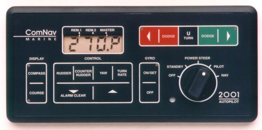
4 BASIC OPERATION AUTOPILOT 1. TO INITIALIZE THE AUTOPILOT: Turn the master select switch to the STANDBY position. The display will show the vessel's current compass heading. If the heading displayed by the autopilot does not agree with the compass, press and hold the GYRO OFF or WIND OFF key, and then use the up or down ARROW key to adjust the heading on the display. 2. TO POWER STEER THE VESSEL: Turn the master select switch to the POWER STEER position. The red and green ARROW keys can now be used to turn the rudder port and starboard. The display will continue to show the vessel's current compass heading. 3. TO BEGIN AUTOPILOT CONTROL OF THE VESSEL: Turn the master select switch to the PILOT position. The vessel will continue on its present heading under autopilot control. Adjust the RUDDER, COUNTER RUDDER, and YAW controls for the best steering. Touch the COMPASS key to view the vessel's actual compass course on the display. Touch the COURSE key to return the programmed course to the display. 4. TO CHANGE THE VESSEL'S COURSE: Leave the master select switch in the PILOT position. Estimate the number of degrees of course change required. Alter course in one degree steps by pressing and releasing either the red or green ARROW key. Alter course by ten degrees per second by pressing and holding either the red or green ARROW key until the display shows the desired course. Press the U-TURN key together with either the red or green ARROW key for 1 second to start a special turn (U-Turn, Emergency Turn, or Continuous Turn) in that direction. 5. TO DODGE THE VESSEL OFF COURSE: Press either the red or green DODGE key for a panic turn in that direction to avoid obstacles in the water. When the vessel has turned far enough to clear the obstacle, press and hold both DODGE keys to hold the vessel off course. The vessel will return to the programmed course at the rate set by the TURN RATE control when the DODGE keys are released. 6. TO INTERFACE WITH A NAVIGATION COMPUTER: Turn the master select switch to the NAV position when the autopilot is to interface with a Navigation Computer. The autopilot will set its own course using information sent to it by the Navigation Computer. To select which Nav Port is active, press the U-TURN key followed by the red ARROW key. To select the Cross Track Error sense (normal or inverted) for the selected Nav Port, press the U-TURN key followed by the green ARROW key. The DODGE keys operate as described in (5) above, except that the vessel will return to the original track to the waypoint, rather than the original course, when the DODGE keys are released. For more complete operating instructions, refer to the CONTROLS and OPERATION sections. P/N V
5 REMOTE CONTROL The autopilot must be turned on at the master control unit to use any remote control. 1. TO USE THE COMNAV 101 REMOTE CONTROL: Take control at the Remote by pressing both its pushbuttons for one second. The decimal point on all displays will move to the REM.1 or REM.2 position. This control operates identically to the autopilot, except that there is a toggle switch, used together with one of the pushbuttons, to dodge or select a U-Turn. 4. TO TAKE CONTROL AT THE AUTOPILOT FRONT PANEL: Take control at the autopilot front panel by pressing both the red and green ARROW keys on the autopilot front panel for one second. The decimal point on all displays will move back to the MASTER position. For more complete operating instructions refer to the REMOTE CONTROLS section. 2. TO USE THE COMNAV 201 REMOTE CONTROL: Take control at the Remote by pressing both its pushbuttons for one second. The decimal point on all displays will move from the MASTER position to the REM.1 or REM.2 position. For direct control of the rudder angle using the lever, place the toggle switch in the TILLER position. To begin autopilot control of the vessel on its present course, place the rotary switch in the PILOT position. The pushbuttons can be used to alter the vessels course, either one degree per push, or, push and hold for 10 degrees per second. 3. TO USE THE COMNAV 211 REMOTE CONTROL: Take control at the Remote by pressing both its pushbuttons for one second. The decimal point on all displays will move to the REM.1 or REM.2 position. The STANDBY, PILOT, and NAV modes operate identically to the autopilot, except there is a toggle switch, used together with one of the pushbuttons, to dodge or select a U-Turn. The TILLER mode provides direct control of the rudder angle using the lever. P/N V1.0-5-
6 LIMITED WARRANTY AGREEMENT Congratulations, you have purchased sophisticated and sensitive marine navigation equipment (the "Equipment") manufactured by ComNav Marine Ltd of # Crestwood Place, Richmond, British Columbia, Canada, V6V 2G1 ("ComNav"). LIMITED ONE YEAR WARRANTY. ComNav warrants to the Purchaser, provided that the recommended installation and maintenance procedures set forth in the manual that has been provided with the Equipment (the "Manual") have been followed, and subject always to the other provisions of this Agreement, that the Equipment is free from defects in workmanship and materials under normal use and service and will perform substantially in accordance with the specifications set forth in the Manual for a period of one (1) year from the date of purchase of the Equipment by the Purchaser. EXTENDED THREE YEAR LIMITED WARRANTY. If; (a) the Equipment is installed: (i) (ii) by an authorized ComNav Dealer; or by someone other than an authorized ComNav Dealer, and such installation has been inspected by an Authorized ComNav Dealer; and (b) the Limited Warranty Registration Card has been returned to ComNav within 14 days of the date of purchase of the Equipment by the Purchaser with Part I thereof having been completed by the Purchaser, and with the Extended Limited Warranty Card having been completed and signed by an authorized ComNav Dealer and returned to ComNav within 14 days of that inspection; ComNav warrants to the Purchaser that the Equipment is free from defects in workmanship and materials under normal use and service and will perform substantially in accordance with the specifications set forth in the Manual for a period of three (3) years from the date of purchase of the Equipment, subject always to the other provisions of this Agreement. NO OTHER WARRANTIES. TO THE MAXIMUM EXTENT PERMITTED BY APPLICABLE LAW, COMNAV DISCLAIMS ALL OTHER WARRANTIES AND CONDITIONS, EITHER EXPRESS OR IMPLIED, STATUTORY OR OTHERWISE WITH RESPECT TO THE EQUIPMENT, INCLUDING BUT NOT LIMITED TO IMPLIED WARRANTIES OR CONDITIONS OF MERCHANTABILITY AND FITNESS FOR THE ORDINARY PURPOSES FOR WHICH THE EQUIPMENT IS USED OR FITNESS FOR A PARTICULAR PURPOSE AND ANY OTHER OBLIGATIONS ON THE PART OF COMNAV, ITS EMPLOYEES, SUPPLIERS, AGENTS, OR REPRESENTATIVES. NO LIABILITY FOR CONSEQUENTIAL DAMAGES. TO THE MAXIMUM EXTENT PERMITTED BY APPLICABLE LAW, IN NO EVENT SHALL COMNAV, ITS EMPLOYEES, SUPPLIERS, OR REPRESENTATIVES BE LIABLE FOR ANY DAMAGES WHATSOEVER, INCLUDING WITHOUT LIMITATION DAMAGE FROM COLLISION WITH OTHER VESSELS OR OBJECTS, INJURY TO ANY PERSON OR PERSONS, DAMAGE TO PROPERTY, LOSS OF INCOME OR PROFIT, BUSINESS INTERRUPTION, OR ANY OTHER CONSEQUENTIAL, INCIDENTAL, RESULTING PUNITIVE, OR SPECIAL DAMAGES ARISING OUT OF THE USE OF OR INABILITY TO USE THE EQUIPMENT, INCLUDING THE POSSIBLE FAILURE OR MALFUNCTION OF, OR DEFECTS IN THE EQUIPMENT, OR ANY PART THEREOF, EVEN IF COMNAV HAS BEEN ADVISED OF THE POSSIBILITY OF SUCH DAMAGES. SOME STATE/JURISDICTIONS DO NOT ALLOW THE EXCLUSION OR LIMITATION OF CONSEQUENTIAL OR INCIDENTAL DAMAGES, SO THE ABOVE LIMITATION MAY NOT APPLY TO THE PURCHASER. REMEDIES NOT TRANSFERABLE. The Purchaser's remedies under this Agreement only apply to the original end-user of the ComNav Equipment, being the Purchaser, and only apply to the original installation of the Equipment. The Purchaser's remedies under this Agreement are not transferable or assignable by the Purchaser to others in whole or in part. P/N V1.0-6-
7 NOTICE OF DEFECT. The Limited Warranty and the Extended Limited Warranty will not apply with respect to any defective Equipment unless written notice of such defect is given to ComNav, by mail to the address for ComNav set forth above, or by facsimile to ComNav at , and is received by ComNav within ten (10) days of the date upon which the defect first became known to the Purchaser. Notices sent by mail will be deemed to be received by ComNav on the seventh (7th) day first following the date of posting in North America and on the tenth (10th) day next following the date of posting anywhere else in the world. Notices sent by facsimile will be deemed to be received by ComNav on the date of transmission with appropriate answerback confirmation. WARRANTY LIMITATIONS. Reversing Pumps & Motors, Hydraulic Linear Actuators, Watch Alarms & Motor Control Boxes which may comprise part of the Equipment are warranted by ComNav for a period of two (2) years under the Extended Limited Warranty described above. All Remote Controls, Remote Cables, Jog Switches, Analog meters (rudder angle indicators), Rudder Angle Indicator Systems & Accessories, Magnetic Compasses & Accessories, Constant Running Pumps, Engine Driven Pumps, Hydraulic Manifolds & Hydraulic Steering are warranted by ComNav for a period of one (1) year under the Limited Warranty described above. IMPLIED WARRANTIES. Any implied warranties with respect to the Equipment are limited to one (1) year. Some states/jurisdictions do not allow limitations on how long an implied warranty lasts, so the above limitation may not apply to the Purchaser. CUSTOMER REMEDIES. ComNav's entire liability and the Purchaser's exclusive remedy against ComNav for the defective Equipment shall be, at ComNav's option, either: (a) repair or replacement of the defective Equipment under the warranties set forth in this Agreement, or, (b) refund of the purchase price of the defective Equipment, all pursuant to and in accordance with the conditions set out below: 1. If the Equipment, or any part thereof, proves to be defective within the relevant warranty period, the Purchaser shall do the following: (a) (b) contact ComNav by phoning to discuss the nature of the problem and obtain shipping instructions (many times a satisfactory solution can be reached without returning the item); and prepare a detailed written statement of the nature of and circumstances of the defect, to the best of the Purchaser's knowledge, including the date of purchase of the Equipment, the place of purchase, the name and address of the installer, and the Purchaser's name, address and telephone number to be sent, along with proof of purchase, to ComNav; 2. If upon examination by either ComNav or by an Authorized ComNav Dealer, the defect is determined to result from defective workmanship or material and if the defect has occurred within the relevant warranty period set forth above, the Equipment or the defective parts thereof will be repaired or replaced, at ComNav's sole option, without charge, and shall be returned to the Purchaser at ComNav's expense. Return delivery will be by the most economical means. Should the Purchaser require the Equipment to be returned by a faster method, the costs incurred by expedited delivery will be prepaid by the Purchaser; 3. No refund of the purchase price for the Equipment will be made to the Purchaser unless ComNav is unable to remedy the defect after having a reasonable number of opportunities to do so. Prior to refund of the purchase price, the Purchaser must submit a statement in writing from an Authorized ComNav Dealer that the installation instructions in the Manual have been complied with in full and that the defect remains; 4. Warranty service shall be performed only by ComNav or by an Authorized ComNav Dealer. Any attempt to remedy the defect by anyone else shall render the warranties set forth in this Agreement void; 5. Charges for overtime, stand-by, holiday and per diem will not be paid by ComNav and are specifically excluded from the warranties set forth in this Agreement. ComNav may, under special circumstances, and with ComNav's PRIOR approval, pay ONE TIME travel costs. Any cost of ferry, boat hire, or other special means of transportation must have prior approval from ComNav. ComNav reserves the right to refuse service charges in excess of one hour if the technician has not contacted ComNav's service department for assistance. Travel cost allowance to service certain Equipment with a suggested retail price of below $2, (Canadian funds or equivalent) is not authorized. If repairs are necessary, these products must be forwarded to ComNav or an Authorized ComNav Dealer at Purchaser's expenses and will be returned as set out in CUSTOMER REMEDIES, Item 2; P/N V1.0-7-
8 6. There shall be no warranty for defects in, or damages to, the Equipment caused by: (a) (b) (c) (d) (e) faulty installation or hook-up of the Equipment; abuse, misuse or use of the Equipment in violation of the instructions set forth in the Manual; shipping, alterations, incorrect and/or unauthorized service; accident, exposure of the Equipment to excessive heat, fire, lightning, salt or fresh water spray, or water immersion except for Equipment specifically designed as, and stated in the Manual to be, waterproof. Water damage to the Equipment due to failure to cover unused receptacles is specifically excluded from any warranty set forth in this Agreement; and improper or inadequate ancillary or connected equipment; 6. This warranty does not cover routine system checkouts, alignment, or calibration unless the service has been authorized in writing by ComNav PRIOR to its commencement; and 8. No Equipment shall be repaired or replaced under warranty if the serial number of that Equipment has been removed, altered or mutilated. CHOICE OF LAW AND JURISDICTION. This Agreement is governed by the laws of the Province of British Columbia, Canada. If you acquired the Equipment outside of Canada, each of the parties hereto irrevocably attorn to the jurisdiction of the courts of the Province of British Columbia, Canada and further agree to settle any dispute, controversy or claim arising out of or relating to this Limited Warranty, or the breach, termination, or invalidity of it, by arbitration under the rules of the British Columbia International Commercial Arbitration Centre ("BCICAC"). The appointing authority shall be BCICAC [or, if the BCICAC shall cease to exist, the Chief Justice of the Supreme Court of British Columbia]. BCICAC shall administer the case in accordance with BCICAC Rules. There shall be one arbitrator and the place of arbitration shall be Vancouver, British Columbia. The United Nations Convention on Contracts for the International Sale of Goods Act, S.B.C. 1990, c. 20, and any other statutory enactments of the United Nations Convention on Contracts for the International Sales of Goods do not apply to this Agreement. THIS LIMITED WARRANTY GIVES THE PURCHASER SPECIFIC LEGAL RIGHTS. THE PURCHASER MAY ALSO HAVE OTHERS WHICH VARY FROM STATE/JURISDICTION TO STATE/JURISDICTION. This Agreement is a legal contract between you (the "Purchaser") and ComNav. By retaining the Equipment for more than thirty (30) days and/or installing and/or using the Equipment, the Purchaser agrees to be bound by the terms of this Agreement. If the Purchaser does not agree to be bound by the terms of this Agreement, the Purchaser may return the Equipment in the same condition in which it was received for a full refund (less shipping and handling costs) within thirty (30) days of purchase. WARNING. The Equipment is an aid to navigation only. It is not intended or designed to replace the person on watch. A qualified person should always be in a position to monitor the vessel's heading, watch for navigational hazards and should be prepared to revert to manual steering immediately if an undesired change of heading occurs, if the heading is not maintained within reasonable limits, or when navigating in a hazardous situation. ALWAYS REMEMBER: WHENEVER UNDER WAY, A QUALIFIED PERSON ON WATCH IS REQUIRED BY LAW P/N V1.0-8-
9 MANUAL PUBLISHED BY: COMNAV MARINE LTD # Crestwood Place RICHMOND, BC V6V 2G1 CANADA -TELEPHONE: (604) FACSIMILE: (604) WEB SITE: TOLL FREE IN CANADA OR THE U.S.A. TELEPHONE: FACSIMILE: REVISED MARCH 2002 P/N V1.0-9-
10 TABLE OF CONTENTS BASIC OPERATION... 3 AUTOPILOT... 3 REMOTE CONTROLS... 4 LIMITED WARRANTY... 5 INTRODUCTION... 9 SPECIFICATIONS INSTALLATION INSTRUCTIONS AUTOPILOT COMPASS DISTRIBUTION BOX RUDDER FOLLOWER REMOTE CONTROLS REMOTE HEADING DISPLAYS NAVIGATION INTERFACE DATA OUTPUT DIP SWITCHES DOCKSIDE SET-UP SEA TRIALS CONTROLS REMOTE CONTROLS SPECIAL TURNS OPERATION WATCH ALARM AND EXTERNAL ALARM GYROCOMPASS INTERFACE WIND VANE INTERFACE ERROR CHECKING PROBLEM SOLVING KVH DIGITAL GYRO COMPASS TO 2001F AUTOPILOTS KVH DIGITAL GYRO COMPASS TO 2001G AUTOPILOTS P/N V
11 INTRODUCTION This autopilot is a microprocessor operated PID (Proportional/Integral/Differential) controller, working from a high quality, externally gimballed magnetic ships steering compass fitted with a flux-gate sensor. An analog to digital converter changes the signals from the sensor into digital heading information with a resolution of 1/2 of a degree, and an overall accuracy of +/- 2 degrees or better. This heading information is compared against the programmed heading, and the desired rudder position determined. The desired rudder position is compared against the actual rudder position transmitted by the rudder follower, and if they are not the same, either the Port or Starboard output line is activated. The Port and Starboard output lines can drive a load at up to 3 amps. They are designed to operate solenoid valves in a hydraulic steering system. The autopilot is designed to accept up to two remote controls. Control can be taken at either remote simply by pressing both its pushbuttons simultaneously for one second. Control is taken at the other remote, or at the autopilot front panel the same way. By adding a remote expander, each remote receptacle on the rear of the autopilot can support up to four remote controls, for a total of eight The autopilot can drive up to four Remote Heading Displays which continuously display the vessel's actual compass heading. The autopilot can run up to 4 rudder angle indicators which continuously display the vessel's actual rudder angle. 1 shows most interconnections between the autopilot, its accessories, and other external equipment. A speed control signal is also available for use with variable speed rudder drives. The outputs, either by themselves or with an optional solid state control box, can be adapted to operate a wide variety of power steering systems. If the autopilot is installed as a retrofit, it is usually possible to use the existing power steering installation. The autopilot can operate from any DC voltage between 10 and 40 volts. The autopilot is equipped to interface with a Loran C Receiver, Satnav Receiver, GPS Receiver, or any other navigation computer which outputs one of the NMEA 0180, 0182, or 0183 formats at either 1200 or 4800 Baud. It can also transmit heading information in a variety of formats. P/N V
12 OPERATING VOLTAGE: POWER CONSUMPTION: SPECIFICATIONS 10 VDC TO 40 VDC 6 WATTS OPERATING TEMPERATURE RANGE: OUTPUT TYPE: HEADING RESOLUTION: COURSE SET RESOLUTION: SPEED CONTROL OUTPUT: HEADING OUTPUTS: SIZE: WEIGHT: -15 TO +60 DEGREES CENTIGRADE OPEN COLLECTOR TRANSISTOR 3 AMPS MAXIMUM 1/2 DEGREE ON MAGNETIC COMPASS 1/2 DEGREE ON 1X GYROCOMPASS 1/3 DEGREE ON 90X GYROCOMPASS 1/6 DEGREE ON 180X OR 360X GYROCOMPASS 1 DEGREEv 2.57 VDC FOR NO MOVEMENT 4.07 VDC FOR MAX SPEED PORT 1.07 VDC FOR MAX SPEED STBD 10 Kohm SOURCE IMPEDANCE DIP SWITCH SELECTABLE BETWEEN REMOTE HEADING DISPLAY or N+1 or BCD NMEA /210 WIDE X 3.75/95 HIGH X 3.25/83 DEEP inch/mm 3/76 inches/mm required behind unit for cabling 4/1.6 lb/kg P/N V
13 Figure AUTOPILOT INTERCONNECTION DIAGRAM IMPORTANT DISTRIBUTION BOX TERMAIL #9 IS A REFERENCE ONLY, IT IS NOT NEGATIVE POWER P/N V
14 Figure 3 IMPORTANT DISTRIBUTION BOX TERMINAL #9 IS A REFERENCE ONLY, IT IS NOT NEGATIVE POWER P/N V
15 INSTALLATION INSTRUCTIONS AUTOPILOT The autopilot is normally mounted in the vessel's wheelhouse. It can also be mounted in a more exposed location such as a sailboat cockpit or on the flying bridge of a sportsfisherman if it is flush mounted and the rear of the autopilot is protected from spray. Select either the bag containing the flush mount bezel and cutting template, or the bag containing the mounting bracket and knobs. If the autopilot is to be bracket mounted, position the mounting bracket so that the front of the autopilot will be easily visible. There must be a minimum of three inches (76 millimetres) of clearance behind the autopilot to allow for cabling. Screw the knobs part way into the threaded holes on both sides of the autopilot rear cover. Insert the autopilot into the mounting bracket, making sure that one plastic spacer is between the cover and the bracket, and the other is between the bracket and the head of the knob. Tilt the autopilot to the desired angle, and tighten the knobs securely. If the autopilot is to be flush mounted, ensure that there is at least six inches (155 millimetres) of depth in the mounting cavity to allow clearance behind the autopilot for cabling. If the autopilot is being flush mounted in an exposed location, care should be taken to ensure that the rear of the autopilot is not exposed to salt spray or other moisture, as the flush mount bezel reduces the effectiveness of the sealing gasket on the rear of the autopilot. To improve the seal on the rear of the autopilot, an extra gasket for the rear cover has been supplied. Unscrew the two large screws from the rear of the autopilot and remove the rear cover. Peel the protective backing off the extra gasket, and carefully position it on top of the one already in the rear cover. Position the cutting template on the panel where the autopilot is to be mounted, and mark the opening onto the panel. Cut the opening in the panel around the outside of the markings. Remove the rear cover, slide the flush mount bezel over the autopilot chassis, and replace the rear cover and screws. Tighten the screws only enough to slightly compress the gaskets. Slide the autopilot into the hole in the panel, and mark the positions of the four mounting holes. Use the supplied screws to mount the autopilot. If you have access to the rear of the mounting panel, the autopilot can be easily removed from the panel by simply unscrewing the two large screws in the rear and sliding the autopilot out, without having to remove the bezel from the panel. The autopilot is supplied with covers over the two remote control receptacles on the back. If either or both of these receptacles are unused, the cover should be left on it. The receptacles are weatherresistant only with the cover on or when a plug is connected to it. Damage caused by exposing a receptacle to the elements will NOT be repaired under warranty. P/N V
16 COMPASS Locate and mount the compass in a position which minimizes magnetic interference. It should be at least three feet away from such equipment as radios, radars, depth sounders, and engine instruments. The compass can be used as a steering compass if desired. If the amount of cable supplied is too short to reach the rear of the autopilot, obtain an extra plug-in length of cable from your dealer. Cutting and splicing the compass cable is NOT recommended. If the heading displayed by the autopilot does not agree with the compass, place the master select switch in the STANDBY position and press the GYRO (WIND) OFF key together with the up or down ARROW key to adjust the offset by the amount of the error. MOUNTING THE SENSOR TO NON- STANDARD COMPASSES The fluxgate sensor supplied with the autopilot can be mounted to a wide variety of "externally gimballed" compasses. The sensor should not be mounted to "internally gimballed" compasses (where the compass card is gimballed and the bowl of the compass is not) because the compass card does not remain parallel to the sensor when the vessel rolls or pitches. This results in large errors between the compass and autopilot. METHOD 1 **** IMPORTANT **** It is important to remember that the compass is a vital part of the autopilot system. Locating it properly, particularly on steel hulled vessels, is essential to ensure proper operation of the autopilot. We recommend that the services of a qualified compass adjuster be used to select the best installation location and to compensate the compass properly for deviation, including that caused by heeling error. Care must be taken not to place compensating magnets too close to the compass, as this will cause the Flux-Gate Sensor, mounted underneath the compass, to read incorrectly. The use of a pair of 3-1/4 inch (83 millimetre) Compensating Quadrantal Spheres is recommended to correct compass deviation on steel vessels, or on other vessels with magnetic compensating problems due to interference from adjacent iron masses such as an engine block or winches. Remove the rear cover from the autopilot. Fasten a pair of voltmeter probes between the SIN and GND testpoints on the Compass Interface Circuit Board (see figure 7). Turn the master select switch on the autopilot to the STANDBY position. Hold the sensor either above or below the compass, and rotate it until a maximum level is observed on the voltmeter. Move the sensor towards or away from the compass until a new maximum level is observed. This is the optimum distance from the compass to mount the sensor, any closer, and the sensor may interfere with the operation of the compass. The accuracy of the sensor, and its sensitivity to external fields, will slowly worsen as it is moved further from the compass. If the reading on the autopilot display decreases when the heading on the compass is increasing, turn the sensor over. Rotate the sensor until the heading on the display of the autopilot matches the reading on the compass and tighten the mounting screw. Rotate the compass through 360 degrees, comparing readings every 20 degrees. If the compass is compatible with the sensor, the readings should agree within +/- 2 degrees (4 degrees total error). P/N V
17 METHOD 2 Mount the compass sensor either above or below the compass, spaced a minimum of 1 inch (25 millimetres) away from the compass card. Turn the master select switch on the autopilot to the STANDBY position. Rotate the sensor until the reading on the autopilot display matches the compass reading. If the reading on the display of the autopilot decreases when the heading on the compass isincreasing, turn the sensor over. Rotate the compass through 360 degrees, comparing readings every 20 degrees. If the readingsdiffer by more than +/- 2 degrees (4 degrees total), remount the sensor a further 1/2 inch (12 millimetres) from the compass, and repeat. Continue repeating until the accuracy of the sensor begins to deteriorate. The final mounting position for the sensor should be the one where the best accuracy was obtained. Either method will determine the optimum distance between the compass and the sensor. Mounting the sensor above the compass reduces the possibility of compensating magnets interfering with the operation of the sensor, but also reduces the visibility of the compass if it is to be used as a steering compass. As a further test, tilt the bowl of the compass so the card tilts relative to the sensor. The heading on the display of the autopilot should not change more than two degrees, with the compass still indicating the same heading. If the heading changes more than two degrees, the magnets on the compass card are not powerful enough, and the compass is not compatible with the sensor. If the accuracy of the compass and sensor combination cannot be made at least +/- 2 degrees, then the compass is not compatible with the autopilot sensor. Your dealer can supply a compass specifically designed for the ComNav 2001 autopilot. P/N V
18 INSTALLATION INSTRUCTIONS DISTRIBUTION BOX Position and mount the distribution box underneath or inside the control console in a DRY location so that the main cable from the distribution box will easily reach the autopilot. Cables are inserted into the distribution box by filing or cutting out the pre-formed ports in the cover. To ensure a neat appearance, the cover has only had the minimum number of openings prepared in advance. The suggested types and gauges of the cables required to hook up the autopilot are listed in Table II. The functions of each set of connections in the distribution box are as follows: 1. PILOT PWR (+) 2. PILOT PWR (-) 3. UNSWITCH. PWR The input voltage appears on this terminal at all times when the breaker which supplies power to the autopilot is on. If a 12 VDC solenoid operated 4-way valve is being used, wire this terminal to the common of the solenoid valve to ensure an adequate voltage supply. If Jog Levers are being used, and are to be active with the autopilot turned off, wire this line to the common of the solenoid operated 4-way valve. WARNING If there is a malfunction of the autopilot or jog lever which continuously activates the 4-way valve, the only way to deactivate the 4-way valve, is to turn off the breaker which supplies power to the autopilot. These two terminals should be hooked to a source of DC power on the boat. The voltage can be from 10 to 40 VDC. The maximum current requirement is less than 4 amps. The autopilot is negative ground. For vessels with positive ground, or with multiple power sources (ie. AC and DC power sources), the autopilot should be electrically isolated from the vessel. This can be done by mounting the autopilot to a non-conducting material, such as wood or fibreglass. This will prevent any damage from ground currents. The power should be taken directly from a breaker or power distribution panel. The autopilot should have its own circuit. This circuit can also send power to the drive unit. If the drive unit is a reversing electric type, it should be wired back to the breaker separately from the autopilot (ie. do NOT wire from the breaker to the drive unit, and from the drive unit to the autopilot). The combined current requirements of a typical ComNav autopilot and reversing motor drive unit will not exceed 25 amps. The only exception would be when a CT2-40A drive unit is used. The CT2-40A drive unit may draw up to 40 amps. 4. PORT OUT 5. STBD OUT These are the two main steering outputs from the autopilot. They are open collector (ie. switch to ground) and can sink up to 3 amps of current. They can be used directly to operate a solenoid operated hydraulic 4-Way Valve, or, as inputs to a solid state control box for electric steering systems (either hydraulic or mechanical). Please note: it is important that you check that your steering drive unit is capable of attaining a hardover to hardover time of 10 to 15 seconds for proper performance. Either output can be overridden with a switched connection (such as a jog lever) between JOG PORT or JOG STBD and JOG COM (terminals 10, 11, and 12) without damaging the autopilot. A pair of diagnostic LED's, one red and one green, are provided in the distribution box to confirm the correct operation of these two outputs. P/N V
19 6. SWITCHED PWR The input voltage appears on this terminal when the autopilot is in any mode except STANDBY or OFF. It can supply up to 3 amps of current for use as the power source for a solenoid operated 4- Way Valve, or, to activate an electric steering system. A yellow diagnostic LED is provided in the distribution box to confirm the correct operation of this output. For 12V 4-Way Valve operation, it is recommended that this output not be used. The common lead from the solenoids should be connected to UNSWITCH. PWR (term. 3). 7. SPEED CONTROL This is a linear signal used with variable speed drive systems. It is centred between +5 VOLTS and COMMON (terminals 8 and 9) when no change of rudder angle is required, and moves up or down from that point by as much as 1.5 VDC for maximum rudder position change to port or starboard respectively V 9. COMMON (REFERENCE ONLY) +5 volts appears across these terminals whenever the autopilot is turned on. These terminals are used by several of the Control Boxes manufactured by ComNav Marine Ltd as a reference for SPEED CONTROL (terminal 7). A yellow LED is provided in the distribution box to confirm the operation of the 5V power supply in the autopilot. 10. JOG PORT 11. JOG STBD 12. JOG COMMON If any jog levers are being used in the system, they should be connected to these three terminals. If the jog levers are to be active all the time, whether the autopilot is turned on or off, connect the common from the solenoid operated 4-way valve to UNSWITCH PWR (terminal 3) rather than SWITCHED PWR (terminal 6). 13. RUDDER PWR 14. RUDDER POS'N 15. RUDDER COM. These three terminals connect to the rudder follower. With the cable from the distribution box unplugged from the rear of the autopilot, and the rudder turned to dead ahead, the resistances between RUDDER PWR and RUDDER POS'N, and RUDDER POS'N and RUDDER COM. should be equal, and each measure approximately 600 ohms. 16. RAI SIGNAL 17. RAI RETURN These two terminals are used to run one or more rudder angle indicators of the zero centre type (ie. the needle should indicate zero degrees of rudder with no power applied to the indicator). The total current drain may not exceed +/- 2.0 milliamps. ComNav supplied rudder angle indicators each draw +\- 0.5 milliamps for full-scale deflection, so up to four may be used. Other manufacturer's rudder angle indicators may require different amounts of current for full-scale deflection. If more than one rudder angle indicator is used, each should have the same current requirements. Multiple rudder angle indicator installations should be wired in parallel. The RAI GAIN potentiometer may need to be adjusted as P/N V
20 described in the DOCKSIDE SETUP section of the manual to make the rudder angle indicator readings match the vessels actual rudder angle. 18. NAV 1 SIGNAL 19. NAV 1 RETURN These two terminals connect to the NMEA 0180, 0182, or 0183 output of a Loran C Receiver, GPS Receiver, or other type of navigation computer so equipped. This Nav Port is selected for use by placing the master select switch in the NAV position, pressing the U-TURN key and then the red ARROW key until the display shows P NAV 2 SIGNAL 21. NAV 2 RETURN These two terminals connect to the NMEA 0180, 0182, or 0183 output of a Loran C Receiver, GPS Receiver, or other type of navigation computer so equipped. This Nav Port is selected for use by placing the master select switch in the NAV position, pressing the U-TURN key, and then the red ARROW key until the display shows P2. for example).these terminals can also be configured as an NMEA 0183 data output port by special factory order. The +5V terminal is included as a convenience for wiring a Remote Heading Display. 26. ALARM OUT 27. WATCH ALARM 28. +PWR PWR The Alarm Out terminal is used to run external alarms. +PWR volts will appear on this line in the event of a fatal alarm (ie. an off course alarm, output failure alarm, etc.), or if the man on watch fails to respond to the autopilot Watch Alarm. The Watch Alarm terminal is an input to the autopilot used to turn the optional Watch Alarm on and off. The +PWR Volt and Common terminals are provided as a convenience for wiring up either the Watch Alarm controller or an External Alarm. 22. TX CLOCK 23. TX DATA V 25. COMMON (REFERENCE ONLY) These terminals are used for transmitting data out of the autopilot to either, a ComNav Remote Heading Display, a satnav, or other type of navigation computer. The function of these terminals is determined by dip switch settings inside the autopilot (see Table III) between ComNav's Remote Heading Display format, the N+1 Heading format (used with the Magnavox MX4102 or MX5102 SatNav equipped with the MX41D N+1 interface circuit board, for example), or the BCD Heading format (used with the Furuno FSN 50 SatNav equipped with the DE-FSN8-8M-1 interface circuit board, P/N V
21 The rudder follower is used to transmit the position of the rudder back to the autopilot. It should be connected to whatever part of the steering system the autopilot controls. Normally, this will be the vessels rudder. INSTALLATION INSTRUCTIONS RUDDER FOLLOWER However, if the vessel has 2 stage steering, where the autopilot drives a control or servo ram, the rudder follower should be mounted to the servo ram rather than to the rudder. If the rudder follower is connected directly to the rudder in this case, uncontrollable hunting of the rudder will result. Normally the rudder follower is mounted in the stern of the vessel, close to the rudder post. A mounting base may have to be fabricated to position the rudder follower properly. Mount the rudder follower in a location where the possibility of damage from any equipment stowed in the area is minimized. If a Medium Duty rudder follower was supplied Mount the rudder post arm on the rudder post using a stainless steel band clamp (not supplied). Bolt the ball joint to the hole in the rudder post arm corresponding to the diameter of the rudder post in inches, making sure the ball is facing upwards. Mount the rudder follower so that the rudder follower arm is the same height as the rudder post arm. The rudder follower is centred when the arm is directly above the cable gland. See Figure 4 and 5 for alignment details. Figure 4 - Correct Linkage Orientation If a Heavy Duty rudder follower was supplied Mount the rudder follower so that the top of the vessel's tiller arm is 1-3/4 inches lower than the top of the rudder follower arm. On the centerline of the vessel's tiller arm, and within 3 to 5 inches from the centre of the rudder post, either: - drill and tap a hole 1/4-20 or, - drill a clearance hole for a 1/4 inch bolt if enough of the threads of the supplied ball joint will come through the tiller arm to permit the supplied nut to be threaded onto it. The rudder follower is centred when the arm is pointing away from the cable gland and is directly over the stainless rivet in the top cover. See Figure 5 for alignment details. P/N V
22 With either rudder follower: The distance between the centerline of the rudder post and the rudder follower must not exceed 24 inches. Make sure that the ball joints on the rudder arm and rudder follower arm are facing upwards as shown in 4. Snap the rod assembly onto the ball joints. Be sure to close the release clamps on each socket. Refer to Figure 2, Figure 4 or Figure 5 and adjust the length of the rod to get the correct geometry with the rudder dead ahead. Table I - Rudder Follower Cable Connections Colour Terminal Description If the length of cable supplied is too short to reach all the way to the distribution box, obtain a terminal strip and sufficient additional cable from your dealer. Mount the terminal strip in a convenient DRY location. Connect the rudder follower cable to the terminal strip and then the additional length of cable. Strip the wires, and attach them to the terminals in the distribution box as shown in Table 1. IMPORTANT If you have installed a hydraulic pump or drive unit, there are several checks that must done during the first few weeks of usage in order to prevent poor or dangerous steering and autopilot performance White 13 +5V Green 14 POS'N Black 15 COM Shield 2 GND If the locking screw in the rudder follower arm has been loosened, or the arm removed from the rudder follower, re-attach the arm and check the potentiometer centring. When the rudder is dead ahead, the electrical resistance between the Black and Green wires and the White and Green wires should be equal (approx. 600 ohms each). Residual Air After installing and bleeding your pump, residual air may be trapped in the hydraulic steering fluid. This air will gradually bleed through the header tank or the highest helm pump and the oil level will go down. Check the oil level several times during the first few weeks of use and add oil as required. Leaking Fittings or Equipment After installing and bleeding your pump, continously monitor the oil level of your header tank or the highest helm pump and add oil as required. If this condition persists, it may be an indication of leakage in your steering system. Check all hydraulic steering parts, fittings and lines for leakage. Be careful to check the installation for any mechanical obstructions or binding of the linkage, and correct it now, before it becomes a problem. The rudder follower is supplied with 50 feet of cable. Run the cable from the rudder follower towards the distribution box, ensuring that it is protected by hose or conduit wherever it passes through fish or cargo holds, or any other area where it could be damaged. P/N V
23 Figure 5 - Rudder Feedback correctly installed to rudder post P/N V
24 INSTALLATION INSTRUCTIONS REMOTE CONTROLS Either optional remote control can be hand-held or permanently mounted. To mount the remote control permanently, drill two holes through the mounting surface 3.5 inches (90 millimetres) apart, one above the other. Drill one more hole in the mounting surface adjacent to the watertight gland in the remote case. As the case is reversible, this may be either above or below the remote mounting location. If a type 101 remote control is plugged into the REMOTE 1 receptacle, Dip Switch 5 should be OFF (or OPEN). If a type 201 or 211 remote control is plugged into the REMOTE 1 receptacle, Dip Switch 5 should be ON (or CLOSED). Dip Switch 6 should be set similarly for the type of remote control plugged into the REMOTE 2 receptacle. Run the cable to the remote control mounting location from the rear of the autopilot, and insert it into the remote control through the watertight gland. Fasten the individual wires into the terminal strip according to the wiring instructions provided with the remote control. Replace the cover. Slide the heads of two #10 stainless steel machine screws into the slots on the rear of the remote control, and lower them into the holes in the mounting surface. Spin on stainless steel lock washers and nuts to complete the installation. To make the remote removable from its mount, drill the two holes in the mounting surface 3.0 inches (76 millimetres) apart, one above the other. Screw two #10 stainless steel screws into the mounting surface, with a gap of 0.1 inches (2.5 millimetres) between the underside of the screw head and the mounting surface. Drop the remote over the screw heads and pull it down to mount it. Lift up and out to remove the remote for handheld operation. Run the cable to the remote control mounting location from the rear of the autopilot, and insert it into the remote control through the watertight gland. Fasten the individual wires into the terminal strip according to the wiring instructions provided with the remote control. Replace the cover. Plug the end of the cable into the REMOTE 1 or REMOTE 2 receptacle on the rear of the autopilot. Make sure that the Dip Switch on the control circuit board of the autopilot (see figure 7) which programs that receptacle is set correctly. P/N V
25 INSTALLATION INSTRUCTIONS REMOTE HEADING DISPLAYS Up to four optional Remote Heading Displays can be run by the autopilot. These can be mounted anywhere convenient using the supplied bracket. A 4-conductor overall shielded cable is required. Refer to the wiring diagram supplied with the Remote Heading Display to connect the cable into the autopilot distribution box. Table II RECOMMENDED CABLES USE TYPE PILOT POWER RUDDER DRIVE SOLENOID VALVE RUDDER DRIVE CONTROL BOX RUDDER FOLLOWER REMOTE HEADING DISPLAYS RUDDER ANGLE INDICATOR NAV INTERFACE HEADING OUTPUT (N + 1) HEADING OUTPUT (BCD) EXTERNAL ALARM WATCH ALARM 2 X 16 GAUGE 3 X 18 GAUGE REFER TO THE INSTRUCTIONS SUPPLIED WITH THE CONTROL BOX 3 X 18 GAUGE 4 X 24 GAUGE W/OVERALL SHIELD 4 X 24 GAUGE 2 X 24 GAUGE W/OVERALL SHIELD. SHIELD TERMINATED AT AUTOPILOT ONLY 2 X 24 GAUGE W/OVERALL SHIELD. SHIELD TERMINATED AT AUTOPILOT ONLY 3 X 24 GAUGE W/OVERALL SHIELD. SHIELD TERMINATED AT AUTOPILOT ONLY 3 X 24 GAUGE 4 X 24 GAUGE P/N V
26 NAVIGATION INTERFACE If the autopilot is being interfaced to a navigation device with any of the NMEA 0180, 0182, or 0183 outputs, determine the type(s) of output format(s) from its data sheets. If an option is available, select the higher numbered output format for better performance. If 0180 and 0182 formats are interspersed on the output line, the autopilot will automatically switch to use the 0182 data and ignore the 0180 data. NMEA 0180 If the autopilot is using NMEA 0180 data to navigate, '180' will be displayed when the TURN key is pressed with the master select switch in the NAV position. The standard baud rate for the 0180 data format is 1200 baud. This format gives the autopilot cross track error information only. Cross track error is the distance and direction the vessel is from the line between the beginning and ending waypoints of the track. The autopilot will use this information to make course adjustments to keep the vessel as close as possible to the track. Because the autopilot does not know the direction to the destination, there will often be one or two swings across the track as the autopilot determines the correct course to steer. If the Nav. Device is set for automatic waypoint sequencing, the autopilot will always overshoot before locking onto the new course, as some cross track error has to build up before the autopilot can know that the Nav. Device has changed waypoints. NMEA 0182 If the autopilot is using NMEA 0182 data to navigate, '182' will be displayed when the TURN key is pressed with the master select switch in the NAV position. The standard baud rate for the 0182 data format is 1200 baud. This format gives the autopilot the same cross track error information as 0180, but adds the heading from the vessel's present position to the waypoint. The autopilot will turn to the indicated heading when the interface is engaged, and will automatically turn to the new heading when the Nav. Device sequences to a new waypoint. It will use the Cross Track Error to make course adjustments to keep the vessel as close as possible to the track to the waypoint. The Heading To Steer information is from the vessel's present position to the destination waypoint, so when the vessel is close to the waypoint (ie. less than 0.2 Nautical Miles), the Heading To Steer will jump, causing the vessel to wander slightly until the Nav. Device sequences to the next waypoint. NMEA 0183 If the autopilot is using NMEA 0183 data to navigate, the three letters of the data sentence being used can be displayed by pressing the TURN key. Please note that the pilot must be in the NAV position. P/N V
27 The standard baud rate for the 0183 data format is 4800 baud. This data format was developed to allow a number of pieces of electronic equipment on the vessel to communicate with each other. It consists of a large number of data 'sentences' which can transmit anything from the vessel's water speed to its present position from one device to another. A data sentence consists of a two letter identification of the sending device, followed by a three letter identification of the data sentence, followed by the corresponding information. The autopilot can understand a number of data sentences which contain steering or speed information. The autopilot ignores the two letter device identifier, and only looks for the three letter sentence identifier, so it will receive information from any Nav. Device which transmits the correct data sentences. Some NMEA 0183 data sentences supply heading from the beginning of track to the end of the track, which remains constant until the Nav. Device sequences to the next waypoint. This is the best type of Heading To Steer information, as it prevents the wandering which may occur when the vessel is close to the destination waypoint as described earlier. Depending on the type of nav device and how it is configured, the autopilot may sound its alarm and display 'Arr' when the vessel is close to a waypoint. The variations of NMEA 0183, which are currently supported by the autopilot, along with the information the autopilot uses from that sentence are listed below: RMA - Loran C Navigation Information, Receiver Status plus Vessel Speed plus Variation RMC - GPS Navigation Information, Receiver Status plus Vessel Speed plus Variation The RMA or RMC data sentence is always combined with the RMB data sentence. RMB - Generic Navigation Information, Cross Track Error plus Heading To Steer from vessels present position to the end of the track (Degree's True only). APB - Autopilot Interface Format, (King Version), Cross Track Error plus Heading To Steer from the vessel's present position to end of track. APB - Autopilot Interface Format, (NMEA Version), Cross Track Error plus Heading To Steer from the vessel's present position to end of track. APA - Autopilot Interface Format, Cross Track Error plus Heading To Steer from beginning to end of track. XTE - Cross Track Error, Cross Track Error plus Receiver Status. XTE is always combined with one on the following: BOD - Bearing Origin to Destination, Bearing from the beginning of the track to end of the track. This is the preferred heading format, or; WBD - Waypoint Bearing Origin to Destination, Proprietary output from Northstar Lorans. Heading to Steer is from the vessel's present position to the end of the track. HSC - Heading Steering Command, Heading To Steer from the vessel's present position to the end of the track. The vessel's speed is read from the RMA or RMC data sentence or one of the following: VBW - Vessel Speed relative to water from Dual Doppler Speed Log. VHW - Vessel Heading and Water Speed P/N V
INSTALLATION MANUAL 2001 AUTOPILOT
 INSTALLATION MANUAL 2001 AUTOPILOT WARRANTY NOTICE Prior to the installation and/or operation of the Equipment, ensure that you read, understand and accept the conditions of the warranties as detailed
OPERATION AND INSTALLATION MANUAL
 AP46 Autopilot OPERATION AND INSTALLATION MANUAL www.tmq.com.au TMQ AP46 Autopilot Page 1 of 34 Ver1.0 07/03/2007 This page is Blank TMQ AP46 Autopilot Page 2 of 34 Ver1.0 07/03/2007 WARNING!...4 INTRODUCTION...5
RAI-M series RUDDER ANGLE INDICATOR SYSTEM
 RUDDER ANGLE INDICATOR SYSTEM RAI-M series SEAFIRST ENGINEERING CO 45-16, Ga Um Dong, Chang Won, Kyong Nam Korea Tel : 82 55 267 1645 Fax ; 82 55 266 1646 http://www.seafirst.co.kr GENERAL Seafirst Rudder
SP-110 Autopilot OPERATION
 SP-110 Autopilot OPERATION www.si-tex.com Warning! WHEN USING THE AUTOPILOT AN ADEQUATE WATCH SHOULD BE MAINTAINED AT ALL TIMES. THE AUTOPILOT MUST BE PLACED IN MANUAL MODE WHEN EVER THE VESSEL IS STATIONARY
AP55 Display OPERATION AND INSTALLATION MANUAL.
 AP55 Display OPERATION AND INSTALLATION MANUAL www.tmq.com.au Index INDEX... 2 INTRODUCTION... 3 System configuration... 3 System Block Diagram... 4 Definition of Terms... 6 Overview of Operation... 8
TS-202 FFU Lever Remote Part Number & Operation & Installation Instructions Version 2.1
 R TS-202 FFU Lever Remote Part Number 20310020 & 20310029 Operation & Installation Instructions Version 2.1 ComNav Marine Ltd. 15 13511 Crestwood Place. Richmond, B.C. Canada. V6V-2G1 Document PN 29010046
frequently asked questions
 Hydra Pilot Fault Codes What do the fault codes for the Hydra Pilot mean? Fault Cause FAULT 100 FAULT 101 FAULT 102 FAULT 103 FAULT 104 FAULT 105 FAULT 106 FAULT 108 FAULT 109 FAULT 110 FAULT 111 FAULT
PLAQUE MFM0680 UNDERWATER LIGHT. Operating Instructions
 PLAQUE MFM0680 UNDERWATER LIGHT Operating Instructions CONTENTS Preface... 3 Features... 3 Precautions... 3 Controls and Connectors... 4 Underwater Light PLAQUE MFM0680... 4 Power Supply Unit MPS021000
WIND CLIPPER KTS ILLUM SCALE INC DEC CLIPPER WIND SYSTEM
 CLIPPER WIND KTS ILLUM SCALE DEC INC CLIPPER WIND SYSTEM TABLE OF CONTENTS INTRODUCTION PRE-TEST OF INSTRUMENT INSTALLING THE MASTHEAD SENSOR UNIT INSTALLING THE DISPLAY NORMAL OPERATION CHANGING THE
URC Voltage Sensor SEN-VOLT for use with MRX units containing sensor ports
 URC Voltage Sensor SEN-VOLT for use with MRX units containing sensor ports URC Voltage Sensor SEN-VOLT 2013 Universal Remote Control, Inc. The information in this Owner s Manual is copyright protected.
ROPV R40 E Series User Manual
 HARBIN ROPV INDUSTRY DEVELOPMENT CENTER ROPV R40 E Series User Manual For Use with the Following ROPV Pressure Vessel Models: R40 300E R40 450E Headquarters Tel:(+86)451-82267301 Fax:(+86)451-82267303
PLAQUE MFM18240 UNDERWATER LIGHT. Operating Instructions
 PLAQUE MFM18240 UNDERWATER LIGHT Operating Instructions CONTENTS Preface... 3 Features... 3 Precautions... 3 Controls and Connectors... 4 Underwater Light PLAQUE MFM18240... 4 Power Supply Unit MPS061000
1420 Autopilot System. Installation & Operation Manual
 1420 Autopilot System Installation & Operation Manual WELCOME Congratulations on your purchase of a ComNav Marine 1420 Autopilot System! At ComNav, we are dedicated to reliability & quality in all our
Installation and Operation Manual
 Installation and Operation Manual WIKA FLR-SBDF / BLR-SBDF Magnetic Level Transmitter (Please retain for future usage) Contact: Gayesco-WIKA USA, L.P. 229 Beltway Green Boulevard Pasadena, TX 77503 www.wika.com
CONUS MSR0680 UNDERWATER LIGHT. Registered Community Design. Operating Instructions
 CONUS MSR0680 UNDERWATER LIGHT Registered Community Design Operating Instructions CONTENTS Preface... 3 Features... 3 Precautions... 3 Controls and Connectors... 4 Underwater Light CONUS MSR0680... 4 Power
This document to be used with Hurley traditional Davits
 ~ InstructIon Manual ~ This document to be used with Hurley traditional Davits WarnIngs WarnIng - Failure to install, maintain, protect, and operate the system properly can cause malfunction resulting
TOP VALVE. Pat. #5,857,486 & 5,944,050. Mid-Range Pressure PSIG Back Pressure and Pressure Relief Valves. Instruction Manual
 TOP VALVE Pat. #5,857,486 & 5,944,050 Mid-Range Pressure 50 232 PSIG Back Pressure and Pressure Relief Valves Instruction Manual Please Note: This instruction manual provides detailed information and instructions
METEOR LSR36500 LIGHTING UNDERWATER POOL LIGHT. Operating Instructions
 METEOR LSR36500 UNDERWATER POOL LIGHT Operating Instructions LIGHTING CONTENTS Preface...3 Features...3 Precautions...3 Components and Connectors...4 Installation...5 Controls...7 Appearance...8 Technical
REACTOR 40 MECHANICAL Configuration Guide
 REACTOR 40 MECHANICAL Configuration Guide Important Safety Information WARNING See the Important Safety and Product Information guide in the product box for product warnings and other important information.
BS Series Basket Strainer
 BS Series Basket Strainer Operating, Installation, & Maintenance Manual Corrosion Resistant Fluid and Air Handling Systems. Dated 04-26-12 PRESSURE DROP SIMTECH strainers are engineered to offer the lowest
Installation, Compensation and Maintenance Instructions for. RITCHIE Compasses. Made In U.S.A
 Installation, Compensation and Maintenance Instructions for RITCHIE Compasses Made In U.S.A All Magnetic Compasses are vulnerable to magnetic interference, which will produce errors, called deviation.
OWNERS MANUAL. Model Shown with optional Primary Mooring Cleats. Portable Mooring System SAFETY OPERATION MAINTENANCE PARTS
 OWNERS MANUAL Model 2400 Shown with optional Primary Mooring Cleats. Portable Mooring System SAFETY OPERATION MAINTENANCE PARTS CAUTION: Before using your new Pier Tender, read rules for Safety, Operation,
FLANGED TWO-PIECE BALL VALVES
 INTRODUCTION This instruction manual includes installation, operation, and maintenance information for FNW flanged split-body ball valves. This manual addresses lever operated ball valves only. Please
KJ4000 Operating Instructions & Parts Manual NSN
 KJ4000 Operating Instructions & Parts Manual NSN 1025-01-473-7710 Mandus Group Ltd. KJ4000 Operators Manual Date: 3 Jan. 2002 TABLE OF CONTENTS General Safety Instructions...Page 1 Operator Instructions...Page
Autopilot setup. VRF (Virtual Rudder Feedback) calibration. Software setup NSS evo2 Installation Manual
 calibration. Software setup NSS evo2 Installation Manual") Autopilot setup Verifying the autopilot connection When an AC12N, AC42N, or SG05 is connected to the NSS evo2 system, the NSS evo2 will automatically detect the autopilot and an Autopilot menu icon will
Autopilot setup Verifying the autopilot connection When an AC12N, AC42N, or SG05 is connected to the NSS evo2 system, the NSS evo2 will automatically detect the autopilot and an Autopilot menu icon will
Freedom8 ShoeBox Compressor Manual
 Freedom8 ShoeBox Compressor Manual Warning!! This product is not a toy! Use or misuse can cause severe injury or death! Use only with adult supervision. This unit is only to be used with tanks, hoses and
Yoke Block Instruction Manual
 Yoke Block Instruction Manual ! WARNING IMPORTANT: READ MANUAL COMPLETELY BEFORE OPERATING THIS DEVICE This manual contains instructions on periodically required checks to be performed by the user. These
J Air and Water Kit Instructions Part# 02584
 J Air and Water Kit Instructions Part# 02584 Unpacking Please open and inspect your package upon receipt. Your package was packed with great care and all the necessary packing materials to arrive to you
FLANGED TWO-PIECE BALL VALVES
 INTRODUCTION This instruction manual includes installation, operation, and maintenance information for FNW flanged split-body ball valves. This manual addresses lever operated ball valves only. Please
T i m i n g S y s t e m s. RACEAMERICA, Inc. P.O. Box 3469 Santa Clara, CA (408)
") RACEAMERICA T i m i n g S y s t e m s Demo Tree Controller Owner s Manual Models 3204D, 3204DW & 3204DX Rev D RACEAMERICA, Inc. P.O. Box 3469 Santa Clara, CA 95055-3469 (408) 988-6188 http://www.raceamerica.com
RACEAMERICA T i m i n g S y s t e m s Demo Tree Controller Owner s Manual Models 3204D, 3204DW & 3204DX Rev D RACEAMERICA, Inc. P.O. Box 3469 Santa Clara, CA 95055-3469 (408) 988-6188 http://www.raceamerica.com
INSTALLATION INSTRUCTIONS AND REFERENCE HANDBOOK
 INSTALLATION INSTRUCTIONS AND REFERENCE HANDBOOK APPLICATION NOTES WIND MEASURING SYSTEMS Document no.: 4189340577BC SW version AGC 3.4X0.X0 or later and AGC 4.00.0 or later Document no.: 4189350050A Table
PILOT PEDAL DRIVE INSTRUCTIONS
 PILOT PEDAL DRIVE INSTRUCTIONS TABLE OF CONTENTS 1. INTRODUCTION 2. IMPORTANT SAFETY AND OPERATING INFORMATION 3. EQUIPMENT 3.1 Items Supplied 3.2 Tools Required 4. ASSEMBLY OF THE PEDAL DRIVE 4.1 Installing
TOP VALVE. Pat. #5,857,486 & 5,944,050. High Temperature: max. 300 F (149 C) Back Pressure And Pressure Relief Valves. Instruction Manual
 Back Pressure And Pressure Relief Valves. Instruction Manual") TOP VALVE Pat. #5,857,486 & 5,944,050 High Temperature: max. 300 F (149 C) Back Pressure And Pressure Relief Valves Instruction Manual PLEASE NOTE: This instruction manual provides information and instructions
TOP VALVE Pat. #5,857,486 & 5,944,050 High Temperature: max. 300 F (149 C) Back Pressure And Pressure Relief Valves Instruction Manual PLEASE NOTE: This instruction manual provides information and instructions
Index Table. Model 794. Installation, Operating and Maintenance Instructions
 CLOCKWISE MANUAL MAKING INTO CCW TABLE Index Table Model 794 Installation, Operating and Maintenance Instructions Black & Webster Products Division 545 Hupp Ave. P.O. Box 831, Jackson, Michigan 49204 2009
Simrad yachting catalog 2007
 26 AUTOSTEERING Electronic intelligence combined with powerful and reliable designs make sure you enjoy boating even more. 27 Tillerpilots Enjoy silence when sailing SIMRAD TP SERIES REMOTE COMMANDER High
˵à Êé OPERATOR'S MANUAL. Autopilot
 KAP-833 KAP833 ˵à Êé OPERATOR'S MANUAL Autopilot Warning! Automatic pilots are designed to be a navigational aid. As an automatic steering aid, an autopilot can alleviate the boredom of hand steering.
Instruction Manual LIMITED 1 YEAR WARRANTY. Hydraulic Punch Driver Read this material before using this product.
 Instruction Manual Hydraulic Punch Driver 902-483 LIMITED 1 YEAR WARRANTY We make every effort to assure that its products meet high quality and durability standards, and warrant to the original purchaser
Sweeper Dual Control. Automatic Sweeper Switching System SW SERIES SWEEPERS SW-4815 SW-4820 SW-4825 MAGUIRE PRODUCTS INC.
 MAGUIRE PRODUCTS INC. SW SERIES SWEEPERS For SW Series Sweeper Models: SW-4815 SW-4820 SW-4825 Sweeper Dual Control Automatic Sweeper Switching System INSTRUCTION AND OPERATION MANUAL Copyright Maguire
Explorer AP380 Autopilot Installation and Operation Manual
 Explorer AP380 Autopilot Installation and Operation Manual www.northstarnav.com IMPORTANT SAFETY INFORMATION Please read carefully before installation and use. DANGER! WARNING! CAUTION CAUTION This is
MODEL 9875 STADIUM BASEBALL SCOREBOARD. Instruction Manual
 UNITEC MANUFACTURING DIVISION MODEL 9875 STADIUM BASEBALL SCOREBOARD (WITH INNING BY INNING SCORING) Instruction Manual Mailing Address: PO Box 260, Yorkville, NY 13495-0260 Plant Address: 34 Main Street,
Compact Triple Cabinet Outlet Station Model Installation and Operating Instructions
 Compact Triple Cabinet Outlet Station Model 6258-1 Installation and Operating Instructions The Porter Compact Triple Outlet Station (6258-1) provides a quick, safe, and reliable method of connection to
Yoke Block Instruction Manual
 Yoke Block Instruction Manual ! WARNING IMPORTANT: READ MANUAL COMPLETELY BEFORE OPERATING THIS DEVICE This manual contains instructions on periodically required checks to be performed by the user. These
Installation, operating and maintenance Instructions for Seemag bypass level indicator
 Issue: S Date: 05-09-14 Type G35 General information The Seetru bypass magnetic level indicator, abbreviate SEEMAG, serves to show the filling level of fluids in tanks, basins, tubes etc. The Seemag operates
INSTRUCTION MANUAL. FLOW CONTROL DRAWERS MANUAL / PLC CONTROL SERIES Model Version Perma Pure LLC Tel:
 PERMA PURE INSTRUCTION MANUAL FLOW CONTROL DRAWERS MANUAL / PLC CONTROL SERIES Model 3300 Version 4.06 Perma Pure LLC Tel: 732-244-0010 P.O. Box 2105, 8 Executive Drive Tel: 800-337-3762 (toll free US)
SI-TEX SP36 Autopilot
 SI-TEX SP36 Autopilot Installation & Operation Manual PN 29010086 V1.0 Warranty Notice Prior to the installation and/or operation of the equipment, please take a moment to read and accept the conditions
GETZ EQUIPMENT INNOVATORS PART NO.: 9G59554 MODEL: MS 36 SC-R HYDROSTATIC TEST PUMP
 GETZ EQUIPMENT INNOVATORS PART NO.: 9G59554 MODEL: MS 36 SC-R HYDROSTATIC TEST PUMP LIMITED WARRANTY Getz Equipment Innovators warrants its products, and component parts of any product manufactured by
SIX R (P ) AND SEVEN R (P ) POSITION CYLINDERS Service Information
 AND SEVEN R (P ) POSITION CYLINDERS Service Information") SIX R431006322 (P -063892-00001) AND SEVEN R431006321 (P -063981--00002) POSITION CYLINDERS Service Information The six and seven position cylinders are medium duty pneumatic positioning devices that operate
SIX R431006322 (P -063892-00001) AND SEVEN R431006321 (P -063981--00002) POSITION CYLINDERS Service Information The six and seven position cylinders are medium duty pneumatic positioning devices that operate
GASGUARD VENT LINE3 Ammonia Sensor OPERATING & INSTALLATION MANUAL
 GASGUARD VENT LINE3 Ammonia Sensor OPERATING & INSTALLATION MANUAL Operating and Installation Manual Warning Use this product only in the manner described in this manual. If the equipment is used in a
Compact Triple Cabinet Outlet Station Model B Installation and Operating Instructions
 PORTER Parker Hannifin Corporation Porter Instrument Division 245 Township Line Rd. P.O. Box 907 Hatfield, PA 19440-0907 USA (215) 723-4000 / fax (215) 723-5106 Compact Triple Cabinet Outlet Station Model
D Series Air and Water Kit Part# 02550
 D Series Air and Water Kit Part# 02550 Unpacking Please open and inspect your package upon receipt. Your package was packed with great care and all the necessary packing materials to arrive to you undamaged.
TECNAUTIC_GmbH. Display Functions with the PB100/200 connected: -- GND Speed -- GND Course -- Heading (Gyro option is recommended) 2 m
 2 m") PB100/200 Sonic Wind Wind, GPS, Compass Display Config: SE=12 di=00 df=20,91,30,34,(61) 35,36,81 Gr=01 n0=00 n1=07 n2=07**) n3=00 Display Functions with the PB100/200 connected: -- Apparent Wind -- True
PB100/200 Sonic Wind Wind, GPS, Compass Display Config: SE=12 di=00 df=20,91,30,34,(61) 35,36,81 Gr=01 n0=00 n1=07 n2=07**) n3=00 Display Functions with the PB100/200 connected: -- Apparent Wind -- True
Model PSI Compressor with 3-Gallon Air Tank 12VDC
 Model 6350 150 PSI Compressor with 3-Gallon Air Tank 12VDC IMPORTANT: It is essential that you and any other operator of this product read and understandd the contents of this manual before installing
92831 TEL: (714) FAX:
 FAX:") Document N0. 1800-03 Copyright 2010 Terra Universal Inc. All rights reserved. Revised Sept. 2010 Terra Universal, Inc. TerraUniversal.com 800 S. Raymond Ave. Fullerton, CA 92831 TEL: (714) 578-6000 FAX:
Document N0. 1800-03 Copyright 2010 Terra Universal Inc. All rights reserved. Revised Sept. 2010 Terra Universal, Inc. TerraUniversal.com 800 S. Raymond Ave. Fullerton, CA 92831 TEL: (714) 578-6000 FAX:
Calibration Gas Instrument INSTRUCTION MANUAL. Release I. Advanced Calibration Designs, Inc.
 Advanced Calibration Designs, Inc. Calibration Gas Instrument INSTRUCTION MANUAL Release I www.goacd.com Instruction Manual Gas Generator Release I TABLE OF CONTENTS I. General Description Page 2 II. Start-Up
AC1810 / AC1810-A TECHNICAL SPECIFICATIONS. Operating Pressure psi ( kgs/cm²) [AC1810] Displacement. Net Weight
![AC1810 / AC1810-A TECHNICAL SPECIFICATIONS. Operating Pressure psi ( kgs/cm²) [AC1810] Displacement. Net Weight](/thumbs/83/88369739.jpg "AC1810 / AC1810-A TECHNICAL SPECIFICATIONS. Operating Pressure psi ( kgs/cm²) [AC1810] Displacement. Net Weight") Technical Specifications Operating Instructions Maintenance Information Troubleshooting Guide Parts Diagrams AC1810 / AC1810-A THE EVOLUTION OF PERFECTION CAUTION: Before attempting to use or service this
Technical Specifications Operating Instructions Maintenance Information Troubleshooting Guide Parts Diagrams AC1810 / AC1810-A THE EVOLUTION OF PERFECTION CAUTION: Before attempting to use or service this
Pressure Dump Valve Service Kit for Series 3000 Units
 Instruction Sheet Pressure Dump Valve Service Kit for Series 000 Units. Overview The Nordson pressure dump valve is used to relieve hydraulic pressure instantly in Series 00, 400, 500, and 700 applicator
Media-Isolated Mag Plus Probe Low Pressure-ISO Kit
 Manual No: 577013-975 Revision: B Media-Isolated Mag Plus Probe Low Pressure-ISO Kit Installation Guide Notice Veeder-Root makes no warranty of any kind with regard to this publication, including, but
RAM 4021 Operation Manual
 RAM 4021 Operation Manual Worldwide Manufacturer of Gas Detection Solutions TABLE OF CONTENTS RAM 4021 For your safety...3 Description...3 Set-up mode...4 Annunciator lights/alarms...4 Operation...5 Calibration...6
ATD /8 x 50 Retractable Air Hose Reel Owner s Manual
 ATD-31166 3/8 x 50 Retractable Air Hose Reel Owner s Manual Features Heavy-gauge, all-steel reel assembly 8-position ratchet mechanism locks reel at desired hose length 5-position adjustable roller outlet
TOP BLEED Position for SeaTalk 2 colour logo ST 30. COMPASS Operation and Installation
 Distributed by Any reference to Raytheon or RTN in this manual should be interpreted as Raymarine. The names Raytheon and RTN are owned by the Raytheon Company. TOP BLEED Position for SeaTalk 2 colour
INSTRUCTION MANUAL MP4AR Remote Convection Gauge Range: 1 x 10⁻³ Torr to 1 x 10+3 Torr
 INSTRUCTION MANUAL MP4AR Remote Convection Gauge Range: 1 x 10⁻³ Torr to 1 x 10+3 Torr A DIVISION OF THE FREDERICKS COMPANY 2400 PHILMONT AVE. HUNTINGDONVALLEY, PA 19006 PARTS LIST 1 3 4 2 # QTY ITEM DESCRIPTION
OPERATING and MAINTENANCE INSTRUCTIONS MAXIS 3K Puller (M3K-M)
") OPERATING and MAINTENANCE INSTRUCTIONS MAXIS 3K Puller (M3K-M) 04/17 (M3K-M) READ AND UNDERSTAND ALL OF THE INSTRUCTIONS AND SAFETY INFORMATION IN THIS MANUAL BEFORE OPERATING OR SERVICING THIS TOOL TABLE
OPERATING and MAINTENANCE INSTRUCTIONS MAXIS 3K Puller (M3K-M) 04/17 (M3K-M) READ AND UNDERSTAND ALL OF THE INSTRUCTIONS AND SAFETY INFORMATION IN THIS MANUAL BEFORE OPERATING OR SERVICING THIS TOOL TABLE
NB/NBR NITROGEN BOOSTER FOR AVIATION SERVICE
 NB/NBR NITROGEN BOOSTER FOR AVIATION SERVICE INSTALLATION, OPERATION & MAINTENANCE MANUAL INTERFACE DEVICES, INC. 230 Depot Road, Milford, CT 06460 Ph: (203) 878-4648, Fx: (203) 882-0885, E-mail: info@interfacedevices.com
In Vivo Scientific, LLC INSTRUCTION MANUAL
 CO 2 Controller In Vivo Scientific, LLC INSTRUCTION MANUAL CONTENTS CONTENTS...1 ABOUT THIS MANUAL...2 INTRODUCTION...2 Cautions and Warnings...2 Parts List...2 Unpacking...2 INSTRUMENT DESCRIPTION...3
Welcome. Warranty Notice. Operator s Warning. General Notice. ComNav Marine Ltd. ComNav Admiral P3 Installation & Operation
 Admiral P3 Wheelmark Autopilot System Installation & Operation Manual 0801/06 USCG Approval Number: 165.110/EC0801/MED3280206 PN 29010075 COMPLIES WITH CE REGULATIONS Welcome Welcome Congratulations on
OPERATING and MAINTENANCE INSTRUCTIONS MAXIS 6K Puller (M6K-M)
") OPERATING and MAINTENANCE INSTRUCTIONS MAXIS 6K Puller (M6K-M) READ AND UNDERSTAND ALL OF THE INSTRUCTIONS AND SAFETY INFORMATION IN THIS MANUAL BEFORE OPERATING OR 04/17 (M6K-M) SERVICING THIS TOOL TABLE
OPERATING and MAINTENANCE INSTRUCTIONS MAXIS 6K Puller (M6K-M) READ AND UNDERSTAND ALL OF THE INSTRUCTIONS AND SAFETY INFORMATION IN THIS MANUAL BEFORE OPERATING OR 04/17 (M6K-M) SERVICING THIS TOOL TABLE
INTRODUCTION BILL OF MATERIALS SPECIFICATIONS & TOOLS PROCEDURES OPERATION OF SEATPOST GIANT LIMITED WARRANTY
 INTRODUCTION BILL OF MATERIALS SPECIFICATIONS & TOOLS PROCEDURES OPERATION OF SEATPOST GIANT LIMITED WARRANTY 1 INTRODUCTION Congratulations on the purchase of your new GIANT CONTACT SWITCH seatpost. This
Adapter Kit 5WAR RA NT Y. For use with EZ-Up Gravity Boots and select Teeter Inversion Tables* NEW! Assembly Instructions FULL YEAR
 NEW! Follow along with your smartphone to make assembly even easier! Adapter Kit For use with EZ-Up Gravity Boots and select Teeter Inversion Tables* Assembly Instructions FULL YEAR 5WAR RA NT Y Specifications
Instruction and Practice Manual
 Instruction and Practice Manual Axiom Sports Manufacturing A Division of Fitec International 3525 Ridge Meadow Parkway Memphis, TN 38175 (901) 366-9144 www.axiomsports.com 1 Thank you for purchasing the
Model 106 DPI "Micro-switch" Installation and Operating Instructions
 Mid-West Instrument Model 106 DPI "Micro-switch" Installation and Operating Instructions BULLETIN NO. IM116DPImicro/09A Replaces --- INSPECTION Before installation carefully check the Model Number on each
210 Series Transmitter with External Electrochemical Sensor
 210 Series Transmitter with External Electrochemical Sensor INSTRUCTIONS Installation and Operation of the AMC-210 Series Transmitter with External Electrochemical Sensor IMPORTANT: Please read these installation
INTRODUCTION TO NETWORK WIND 3 MOUNTING THE UNIT 14 SELECTING THE DISPLAY MODE 5 ABBREVIATIONS AND DEFINITIONS 17
 CONTENTS CONTENTS 1 INSTALLATION 14 GENERAL INTRODUCTION TO B&G NETWORK 2 SITING THE UNIT 14 INTRODUCTION TO NETWORK WIND 3 MOUNTING THE UNIT 14 EXAMPLE SYSTEMS USING NETWORK WIND 4 SPECIFICATION 16 SELECTING
User Instruction Manual
 User Instruction Manual 4500 psi Air Compressor Ver 2, 1.18 Contents Parts Included...3 Assembly Instructions...3-5 Operation Instructions...6-7 Oil Change Intervals...8 Air Filter Replacement...9 Setting
SPECIFICATIONS TABLE Maximum Air Pressure 115 PSI Air Tank Capacity 20 Gallons
 SPECIFICATIONS TABLE Maximum Air Pressure 115 PSI Air Tank Capacity 20 Gallons Air Flow Capacity 6.2 CFM at 40 PSI 5.2 CFM at 90 PSI Motor 2.5 HP Working / 4 HP Peak 120 Volt / 60 Hz / 13 A / 1-Phase Required
INSTRUCTION MANUAL. January 23, 2003, Revision 0
 INSTRUCTION MANUAL Model 810A In-Vitro Test Apparatus for 310B Muscle Lever January 23, 2003, Revision 0 Copyright 2003 Aurora Scientific Inc. Aurora Scientific Inc. 360 Industrial Parkway S., Unit 4 Aurora,
NOVALYNX CORPORATION MODEL WEATHER STATION INSTRUCTION MANUAL
 NOVALYNX CORPORATION MODEL 100-1950 WEATHER STATION INSTRUCTION MANUAL Receiving and Unpacking Carefully unpack all components and compare to packing list. Notify NovaLynx Corporation immediately concerning
User s Manual. USB Golf Simulator. Contents
 USB Golf Simulator User s Manual Contents safety information...1 identifying the components...2 assembly in 3 easy steps...3 plug & play...4 playing tips...5 care...6 troubleshooting...7 notes...8 warranty...9
Digital Vacuum Regulator
 Temperature Control for Research and Industry Digital Vacuum Regulator User s Manual Model 300 INDEX SECTION PAGE 1. QUICK OPERATING INSTRUCTIONS........................... 3 Safety Notices.................................................
PART 5 - OPTIONS CONTENTS 5.1 SYSTEM EXPANSION 5-3
 PART 5 - OPTIONS CONTENTS Para Page 5.1 SYSTEM EXPANSION 5-3 5.2 SENSORS 5-3 5.2.1 Trim Angle Sensor 5-3 5.2.2 Mast Rotation Sensor 5-3 5.2.3 Heel Angle Sensor 5-3 5.2.4 Barometric Pressure Sensor 5-3
PRODUCT SUPPORT MANUAL YACHT BEAM 6M Searchlight Remote Control System with Joystick Remote Control Panel
 PRODUCT SUPPORT MANUAL YACHT BEAM 6M Searchlight Remote Control System with Joystick Remote Control Panel The Yacht Group - 4545 Ponce de Leon Blvd. Coral Gables FL 33146 Tel. 305.667.5811 - Fax. 305.663.5551
AMP Oil Free Manual AMP 50-8-TC AMP 50-6-D AMP General User and Maintenance Instructions
 AMP Oil Free Manual AMP 50-8-TC AMP 50-6-D AMP 50-24 General User and Maintenance Instructions Silentaire Technology 8614 Veterans Memorial Dr. Houston, TX 77088 800-972-7668 Fax 832-327-0669 www.silentaire.com
User's Manual. Heavy Duty Dissolved Oxygen Meter. Model
 User's Manual Heavy Duty Dissolved Oxygen Meter Model 407510 Introduction Congratulations on your purchase of Extech's Heavy Duty Dissolved Oxygen / Temperature Meter which simultaneously displays Dissolved
Marschalk Model # 94000
 Marschalk Model # 94000 12-volt DC Portable oil-less Air Compressor Operation Manual 27250006 REV 1 9/13/05 Table of Contents CHAPTER 1: SYSTEM DESCRIPTION... 5 FUNCTION AND THEORY... 5 SYSTEM COMPONENTS...
FLUSHMATE III FLUSHMATE FLUSHOMETER - TANK SYSTEM. Owner s Service Manual. 503 Series. 503 Series
 Owner s Service Manual 503 Series FLUSHMATE III FLUSHOMETER - TANK SYSTEM 503 Series FLUSHMATE A Division of Sloan Valve Company 30075 Research Drive New Hudson, MI 48165 800-533-3450 248-446-5300 http://www.flushmate.com
MODEL NUMBER: PSI AIR SOURCE KIT 200 PSI Compressor on 2.0 Gallon 200 PSI Air Tank
 IMPORTANT SAFETY INSTRUCTIONS CAUTION - To reduce risk of electrical shock or Electrocution: MODEL NUMBER: 20008 200 PSI AIR SOURCE KIT 200 PSI Compressor on 2.0 Gallon 200 PSI Air Tank IMPORTANT: It is
DISASSEMBLING & REASSEMBLING CARTRIDGE INSTALLING SEATPOST ON BIKE
 INTRODUCTION BILL OF MATERIALS SPECIFICATIONS & TOOLS PROCEDURES DISASSEMBLING & REASSEMBLING CARTRIDGE INSTALLING SEATPOST ON BIKE OPERATION OF SEATPOST GIANT LIMITED WARRANTY 1 INTRODUCTION Congratulations
ALTERNATOR RACKS 135, 170 & 190 INSTRUCTIONS
 Figure A Item # Description Quantity 1 Alternator Rack 1 1 3 4 11 5 10 8 2 Lower Mount Kit (see detail) 2 3 16mm M5 Swivel-Mount Bolt 2 4 M7 Washer 2 5 M6 Lock Nut 2 6 Lock Washer 2 7 Swivel Mount 2 8
453 Series Steam Heated Vaporizing Regulator
 ADI 0453A Certified ISO 9001:2000 453 Series Steam Heated Vaporizing Regulator INSTALLATION AND OPERATION INSTRUCTIONS Before Installing or Operating, Read and Comply with These Instructions Controls Corporation
444C DUAL PERFORMANCE VALUE PACK
 (Chrome) PART NO. 44432 IMPORTANT: It is essential that you and any other operator of this product read and understand the contents of this manual before installing and using this product. SAVE THIS MANUAL
Steer to Wind angle, Wind Mode, when connected to the h1000 Wind Interface
 h1000 pilot introduction overview Congratulations on your purchase of the h1000 Pilot from B&G. The h1000 Pilot is the latest in autopilots from B&G and represents B&G s commitment to providing our customers
310 SERIES TILT-TO-LOAD ROTATOR. The Specialist In Drum Handling Equipment
 OPERATOR S MANUAL FOR MORSE TILT-TO-LOAD DRUM ROTATOR SAFETY INFORMATION: While Morse Manufacturing Co. drum handling equipment is engineered for safety and efficiency, a high degree of responsibility
Installation and Operation 370ESP (Electric Single-Point Purger) & 370ESPR (Retrofit Purger)
 & 370ESPR (Retrofit Purger)") IB-77 Installation and Operation 370ESP (Electric Single-Point Purger) & 370ESPR (Retrofit Purger) These installation, operation and technical instructions should be used by experienced personnel as a
IB-77 Installation and Operation 370ESP (Electric Single-Point Purger) & 370ESPR (Retrofit Purger) These installation, operation and technical instructions should be used by experienced personnel as a
400C & 450C DUAL PERFORMANCE VALUE PACKS
 (Chrome) PART NO. 40013 (Silver) PART NO. 45012 (Chrome) PART NO. 45013 IMPORTANT: It is essential that you and any other operator of this product read and understand the contents of this manual before
Preferred Instruments Danbury, CT USA
 Tank Level Sensor Model TG-EL-WF-xx Installation & Operation Instructions SDI-TG-EL-WF March 6, 2006 Preferred Instruments Danbury, CT USA www.preferredinstruments.com CONTENTS Installation Pg. 2 Calibration
Model 130M Pneumatic Controller
 Instruction MI 017-450 May 1978 Model 130M Pneumatic Controller Installation and Operation Manual Control Unit Controller Model 130M Controller is a pneumatic, shelf-mounted instrument with a separate
INSTALLATION. and INSTRUCTION MANUAL. for QUALITY AIR BREATHING SYSTEMS. Model 50-P-Mini Portable Systems Outfitted with ABM-725 Monitor
 INSTALLATION and INSTRUCTION MANUAL for QUALITY AIR BREATHING SYSTEMS Model 50-P-Mini Portable Systems Outfitted with ABM-725 Monitor M A R T E C H S E R V I C E S C O M P A N Y P.O. Box 7079 OFFICE: (507)
GG-VL2-NH3 AMMONIA VENT LINE SENSOR. Installation and Operation Manual
 GG-VL2-NH3 AMMONIA VENT LINE SENSOR Installation and Operation Manual 2 GG-VL2-NH3 Warning Use this product only in the manner described in this manual. If the equipment is used in a manner not specified
97C COMPRESSOR KIT 12V PART NO C COMPRESSOR KIT 24V PART NO C COMPRESSOR KIT PART NO
 97C COMPRESSOR KIT 12V PART NO. 00097 97C COMPRESSOR KIT 24V PART NO. 02497 98C COMPRESSOR KIT PART NO. 00098 97C 98C IMPORTANT: It is essential that you and any other operator of this product read and
MODEL NUMBER: M20005 AIR SOURCE KIT. 30% Duty Compressor on. 2.0 Gallon Air Tank SAVE THIS MANUAL FOR FUTURE REFERENCE
 MODEL NUMBER: M20005 AIR SOURCE KIT 30% Duty Compressor on 2.0 Gallon Air Tank SAVE THIS MANUAL FOR FUTURE REFERENCE USER MANUAL IMPORTANT SAFETY INSTRUCTIONS CAUTION - To reduce risk of electrical shock